s mpc-awmrl all-weather lcd displays
TRANSCRIPT

MPC-AWMRLAll-Weather
LCD Displays
User Manualwww.MarinePC.com
N
S
EW MARINE PCMARINE PC
Information DisclaimerThis MarinePC User Manual is provided “as-is”, without warranty of any kind, either expressed or implied, including but not limited to the implied warranties or merchantability and fitness for a particular purpose.
Documentation Change NoticeThe information in this User Manual is subject to change without prior notice in order to improve readability and reliability as well as design and function. These changes shall be incorporated in a new revision, available from the product and/or download section of the MarinePC web site, www.marinepc.com.
LiabilityIn no event shall MarinePC be liable for direct, indirect, special incidental or consequential damages arising out of the use of or the inability to use MarinePC’s product or its documentation, even if advised of the possibility of such damages.
EndorsementProduct names mentioned herein are used for identification purposes only and may be trademarks and/or regis-tered trademarks of their respective companies.
CopyrightThis document contains proprietary information protected by copyright. All rights are reserved. No part of this manual, in whole or part, may be reproduced by any means, in any form, without prior written permission of MarinePC.
w w w . m a r i n e p c . c o m
Owner RecordHere is an easy-to-locate form to record the unit’s serial number, and from the invoice, record the invoice date. The unit’s serial number is located on the back panel.
If the unit ever requires service, please refer to this information when contacting the MarinePC Service Center.
Product Serial Number Invoice Date
MPC-AWM__RL ____ / ____ / ____
MPC-AWMRL-UM(B) 1/2011
Product Serial Number Invoice Date
MPC-AWM__RL ____ / ____ / ____
MPC-AWMR
All-WeatherLCD Displays
User Manual
www.MarinePC.com

4 MPC-AWMR-UM(B) 1/2011
Table of ContentsIntroduction .................................................................................................................................5
Safety ..............................................................................................................................................6
Product Care and Maintenance ............................................................................................8
System Set-up...........................................................................................................................10
Installation .................................................................................................................................11
Cable Connections..................................................................................................................13
Computer Hook-up ................................................................................................................15
Operator Controls ...................................................................................................................17
On-Screen Display (OSD) ......................................................................................................18
Optional Touch Screen Display ..........................................................................................24 Appendix A - Mechanical Drawings ................................................................................31
Appendix B - Troubleshooting ...........................................................................................31
Appendix C -Technical/Environmental Specifications...............................................34

MPC-AWMR-UM(B) 1/2011 5
Welcome.
With this purchase of an All-Weather Monitor, MPC-AWMRL Series, we welcome you to MarinePC’s family of ruggedized marine grade products.
You will soon become familiar with the quality difference in this LED backlit sunlight-readable (~1 to 1,000 nits) Monitor, specifically designed for use in marine environments. MarinePC has incorporated the latest optical engineering to achieve optimal viewability in all lighting condi-tions.
The MPC-AWMRL handles a wide-range of severe environments, making it the first choice of serious mariners for their demanding applications. Designed to be rugged, this 800 x 600 SVGA (or 15”, 1028 x 768 XGA) Flat Panel Display is engineered to thrive in the marine environment where you will put it to work.
Housed in a milled billet aluminum case, the slim-profile MPC-AWMRL is light weight and watertight, with fully sealed (IP67) connectors. Engineered to be low-power to conserve power, the MPC-AWMRL has one video input: Computer VGA (RGB).
You may have purchased the MPC-AWMRL with the optional Analog Resistive Touch Screen; within this User Manual are instructions for configuring this feature. Other options include a high res 1024x768 LCD (10.4” & 12.1” only) and a pass-through USB port.
Our MarinePC Service and Support Team is prepared to assist you – we are MarinePC.
6 MPC-AWMR-UM(B) 1/2011
SAFETYGeneral Safety Instructions• BeforeoperatingtheMPC-AWMRLMonitor,readthisUserManualthoroughly• RetainthisUserManualforfutureuse• Verifythecomputersystemcapability(seeSystemSet-up)toinsureoperationof
the Monitor• Forexpeditiousinstallation,followtheseUserManualinstructionsinthe
sequence presented• AdheretoallCautionandWarningsonsystempartsandasstatedinthisUser
Manual• AllUserManualinstructionsforinstallationandoperationmustbefollowed precisely• AdjustonlythosecontrolscoveredbytheUserManual’soperatinginstructions;
improper adjustment of other controls voids the unit’s warranty and may result in unit damage, and
• Adheretolocalinstallationcodes.
General Unit Safety• Alwaysdisconnecttheunitfromthepowersourcebeforecleaning• Donotoperatetheunitwithadamagedcord• Donotoperateiftheunithasbeendroppedordamaged.Theunitneedsinspected
by qualified MarinePC Service Personnel• Positionthepowercordsoitshallnotbeincontactwithhotsurfaces• Donotallowanythingtorestonthepowercord,and• Donotplacethepowercordwherethereshallbefoottraffic.
General Safety Precautions
• Powercordmustbeconnectedtoaproperlywiredandgroundedpowersource• Anyequipmenttowhichtheunitshallbeattachedmustalsobeconnectedtoproperly
wired and grounded power sources• Donotconnectordisconnecttheunitduringanelectricalstorm• Donotremovetheunitcovers–therearenouserserviceablepartsintheunit• Donotdisassembleormodifytheunittoavoidthepossibilityofelectricalshock,
damage to electrical components or scratching the Display surface, and• Disassemblyoftheunitvoidsthewarranty.
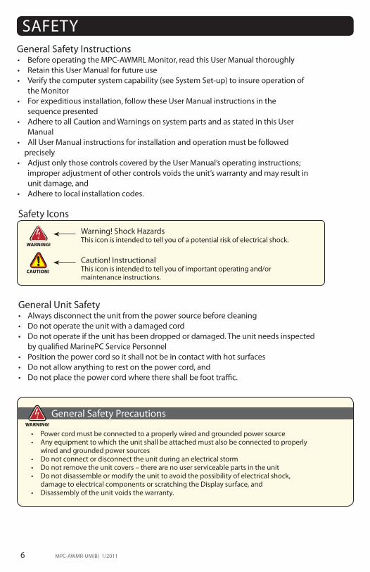
WARNING!
CAUTION!
Warning! Shock HazardsThis icon is intended to tell you of a potential risk of electrical shock.
Caution! InstructionalThis icon is intended to tell you of important operating and/ormaintenance instructions.
Safety Icons
WARNING!

MPC-AWMR-UM(B) 1/2011 7
Electrical SAFETYConnecting Cables• DisconnectthepowertothecomputerwhentheMonitorisbeinginstalled,and• Uponinstallation,verifythepowerconnectorissecurelyseatedontheunit.
Ratings and GroundingThis unit may be operated from an 8-30 VDC power source (external AC optional). • Usethesuppliedpowercable,and• Alwaysconnecttoaproperlygroundedpowersource. Protection on Servicing Servicing - User • Usercareislimitedtocleaningtheunit• Donotdisassembleormodifytheunittoavoidthepossibilityofanelectricalshock,
damage to electrical components or scratching the Display surface, and• Disassemblyvoidsthewarranty.
Servicing - MarinePC MarinePC Qualified Service Personnel may be required if the unit:• Doesnotoperatenormallywheninstallationinstructionsarefollowed• Doesnotoperatenormallywhenoperatinginstructionsarefollowed• Hasbeendroppedordamaged,or• Exhibitsadistinctchangeinperformance,indicatinganeedforservice.
Shipping If the unit should need to be shipped to the MarinePC Service Center, the original packing material should be used to insure safety in shipping. Repack the unit as it would have originally been received from MarinePC.
Fluids from LCD Display
• IftheMonitorshouldeverbecomeshattered,donottouchfluidsfromanLCDDisplay• Iffluidshouldgetonhandsorclothing,immediatelywipeoffwithliquidsoaporrubbing
alcohol; wash with water; consult with a doctor, and• Iffluidgetsintheeyes,flusheyesimmediatelywithwaterforaminimumof15minutes;
consult with a doctor.
This equipment generates, uses and can radiate radio frequency energy. If not installed with the unit’s accompanying cables, it may cause harmful interference to radio communications.
Radio Frequency Interterence
CAUTION!
CAUTION!

8 MPC-AWMR-UM(B) 1/2011
This MPC-AWMRL Monitor has been designed to provide optimum performance and service without any required scheduled maintenance other than occasional cleaning.
Display Screen Cleaning • Avinegar-basedcleanerispreferredtopreventstreakinganddegradationofthe
coatings, or • Anon-abrasiveglasscleanersuchasaprofessionalfoamglasscleaner• Applythecleaningsolutiontoasoftcleancloth,dampeningslightly• Keepafreshsideofthecleaningclothtowardsthescreensurfacetoavoid
scratching it with accumulated grit, and• Tominimizetheriskofabrasiontothescreen,airdryingisrecommended.
Disconnect cabling from the Touch Screen Display before cleaning. A Touch Screen Display will be activated by cleaning the Display. This may create a potentiallydangerous condition.
Optional Touch Screen Cleaning• Useaspecialscreencleaningtissueorasolutionspecificallyformulatedfor
antistatic coatings. Follow the manufacturer’s instructions, or• Lightlydampenasoftcleanclothwithwaterorageneralpurposemilddetergent
solution•Keepafreshsideofthecleaningclothtowardsthescreensurfacetoavoid
scratching it with accumulated grit, and• Tominimizetheriskofabrasiontothescreen,airdryingisrecommended.
Monitor Enclosure• Cleantheunitenclosurewithasoftcleanclothlightlydampenedwitha
general purpose mild detergent solution• Torinse,wipedownwithcleanwater,and• Drywithasoftcleancloth.
Optional Touch Screen
PRODUCT CARE AND MAINTENANCEProduct Care
• Donotuseabrasivecleanersorsolvent-based(flammable)cleanersontheFlat Panel or Touch Screen Display, its enclosure or any other electrical de-vice (cables, power cord, etc)
• DonotusepaperproductsastheymayscratchtheDisplayscreen,and• DonotdirectlyapplycleaningsolutionstotheDisplayscreen.
Turn off the Monitor power before cleaning the Monitor, optional Touch Screen or unit’s enclosure.
WARNING!
CAUTION!
WARNING!
In marine or similar environments, an added benefit of a vinegar-based
cleaner is its effectiveness in dissolving salt deposits.

MPC-AWMR-UM(B) 1/2011 9
To avoid risk of electrical shock, do not disassemble the unit’s enclosure. Users cannot service the Monitor. User maintenance is restricted to cleaning, as ex-plained. Disassembling the unit voids the warranty.
Long-term Storage• Forlong-termstorage,itissuggestedtheunitbestoredinanormalindoorenviron-
ment and the Display glass be protected from accidental damage• Forpedestalmountunits,disconnectthecable(s)andloosenthearmadjustmentto
a point where the ball can be removed from the arm, or• ForFlushorPanelMountunits,covertheproductwithaprotectivecoveringthat
shall not scratch or transfer any dyes to the Display screen.
Maintenance
Other MaintenanceOnly MarinePC Qualified Service Personnel shall perform all maintenance except for the power cord replacement described above.
To avoid shock and fire hazards, replaced the unit’s power cord if:• Insulationbecomesdamaged,or• Alooseconnectionissuspected.
Power Cord
WARNING!
WARNING!

10 MPC-AWMR-UM(B) 1/2011
SYSTEM SET-UPSystem RequirementsThe computer that the MPC-AWMRL is connected to must have this capability:• Videocardsettingwitha4:3aspectratioandaminimumresolutionof640x480pixelsupto
1280x1024 • IftheoptionalTouchScreenDisplayisordered,anavailableCOMorUSBportforthe connector is required.
Shipping Box ContentsThe MPC-AWMRL is shipped in a custom box with shock isolating design. We recommend you save the box and all packaging materials in case the unit would need to be returned to the MarinePC Service Center. (Figure 1)
In the shipping box you shall find:• MPC-AWMRLunit• PowerCable• VGACable• MountingSystemandHardware• TouchScreenCableiftheoptionalTouchScreenisordered•USBCableiftheoptionalUSBPass-throughisordered,and• UserManual
Figure 1

MPC-AWMR-UM(B) 1/2011 11
INSTALLATIONThe MPC-AWMRL is designed to be mounted with a universal ball-and-socket mounting kit, on a flatsurfacewithorwithoutacutout,oroptionalFlushMountconfiguration.
Pedestal MountThe MPC-AWMRL is normally shipped with a RAM® universal ball-and-socket system mounting kit (Figure 2). By installing the Monitor with this kit, the user can quickly adjust the viewing angle to improve viewability in changing environments. This ball-and-socket system has proven to be successful in supporting an extreme amount of weight in highvibrationanddifficult-mountapplications.SeeAppendixAforlinktodrawings.
Locate the ball-and-socket system in the shipping box. The kit consists of two RAMballs on mounting plates and a RAM arm, with an adjustable T-knob and a packet ofthree (3) M4 x 10 counter-sunk stainless screws for mounting to the MPC-AWMRL.
Figure 2
Figure 3 Figure 4
Mounting Holes

12 MPC-AWMR-UM(B) 1/2011
There are three mounting holes in the back of the Monitor for the ball mounting plate. Take care not to strip the screw holes or over tighten. (Figure 4)
• Lineuponeoftheballmountingplatesonthesethreeholes(Figure4)• Withthree(3)M4x10counter-sunkstainlessscrewsattachthismountingplatetothebackof
the MPC-AWMRL. • MountthesecondballmountingplatewheretheMonitorshallbeinstalled• InserteachballintotheRAMarm• LightlytightenthearmaroundtheballsusingtheT-knobonthearm(Figure2,4)• AdjusttheMonitortotheviewingpreference,and• TightentheT-knobtoholdtheMonitorinposition.
Itisrecommendedtheremainingballbemountedonaflatsurface.Becauseofthevarious surface substrates the Monitor shall be mounted on, the installer shall provide the screws to mount the other ball.
Panel MountThe Panel Mount installation should be specified at the time of order; the ball-and-socket mount system will not be included in the shipping box.
The mounting hardware packet is included with the unit accessories in the shipping box. This packet includes four (4) threaded screws (approximately 7.6 cm [3”] long), four(4)Nylocknutsandfour(4)flatwashers.Forinstallation,therearefourtappedmounting holes on the four corners of the unit’s rear panel.
It is recommended the installer refer to the mount drawings on MarinePC’s web site, with (link address listed in Appendix A) for the exact measurements of the unit’s rear panel pod. These should be helpful when the installer cuts the required space for the Panel Mount installation.
Take care not to strip the screw holes or over tighten
as the enclosure is aluminum.
Flush Mount with Optional BezelWiththeoptionalFlushMountBezel,theMPC-AWMRLFlatPanelDisplaymaybemountedflushwith the mounting surface; the ball-and-socket mount system will not be included in the ship-ping box.
For the mount diagram of the optional Flush Mount Bezel, refer to the mount draw-ings on MarinePC’s web site, listed in Appendix A. When the placement site has been decided, it is recommended the installer use the measurements listed in the mount diagram of the optional Flush Mount Bezel when cutting the opening for the Monitor’s installation.
Note the locations of the milled holes in the Flush Mount Bezel. Drill corresponding holes into the substrate where the Monitor shall be mounted. The installer shall need to supply screws for this type of installation.
CAUTION!
Take care not to strip the screw holes or over tighten
as the enclosure is aluminum. CAUTION!

MPC-AWMR-UM(B) 1/2011 13
CABLE CONNECTIONSCables• TheMPC-AWMRLispackagedwithtwocables:
VGA and DC Power• TheACPowerAdapterisoptional.(Figure6)
Connectors are located on the bottom of the unit housing, from left to right: VGA, S-Video, Optional USB Pass-through, Optional Touch, Power and BNC. (Figure 8)
Connectors are physically unique to insure the installer makes the proper connections.
CAUTION!
Use care when inserting or removing connectors.
Connectors
1 VGA Input2 DC Power Input
Figure 5
Figure 6
12
3
4
1 Optional USB Input2 Optional Touch Input3 Power Input4 VGA Input
Figure 7
VGA Connector• TheIP67sealedVGACable,3m(10ft),isintheproductaccessorybox• Lineupthereddotsontheconnectors• PushthecableconnectorintotheMonitor’sbackpanelconnector,
#4 in Figure 7, and• PlugthestandardDB-15(video)femaleconnectortothecomputer’s
video source; secure.

14 MPC-AWMR-UM(B) 1/2011
DC Power Connector• TheIP68sealedDCPowerCable,3m(10ft),isintheaccessorybox• Lineupthereddotsto#5 in Figure 8• Pluginthequick-connectthree-pinconnector• Todisconnect,pulltheoutsideringontheconnectorawayfromtheunituntilthe
cable is free• Therearetwoflyingleads:negative:black(-)andpositive:yellow,labeledwith
(+), and• ConnecttheflyingleadstothecorrespondingpolarityontheDCvoltagesource,
primary terminal.
Optional AC Power Connector• TheoptionalACPowerAdapterCableSetconsistsofa3m(10ft)cable,the
power adapter and a 1.8 m (6 ft) cable• Thecableacceptsvoltagefrom110to250VACandfrequencyfrom47to63Hz• TheACpowerplugisstandardfor120VAC/60Hz,commoninNorthAmerica,and• Lineupthereddotsto#5 in Figure 8•Todisconnect,pulltheoutsideringontheconnectorawayfromtheunituntilfree.
Optional USB Pass-through Connector• TheoptionalUSBPass-throughConnectorisanIP67sealedfour-pinconnector• ThecustomUSBCableiswithshippingboxaccessories;itis.6m(2ft)•Lineupthereddotsto#3 in Figure 8, and•Plugtogether.•Todisconnect,pulltheoutsideringontheconnectorawayfromtheunituntilfree.
Optional Touch Screen Connector• TheoptionalTouchScreenConnectorisanIP67sealedfour-pinconnector• TheconnectorisnexttotheVideoandPowerConnector• Lineupthereddotsto#4 in Figure 8, and • Plugtogether.
CAUTION!
Confirm the DC connections are made to the correct polarity.

MPC-AWMR-UM(B) 1/2011 15
COMPUTERHOOK-UP
Prior to connecting the MPC-AWMRL to the computer, verify the computer display properties are set to 800 x 600 (SVGA) pixels or for the 15” Monitor, 1024 x 768 (XGA) pixels. Matching the video setting with the native resolution of the LCD will always yeild the best picture quality.
1. Right mouse click on an open area of the desktop screen to bring up the Desktop Menu.
2. Left mouse click on Properties to open the Display Properties menu.
3. Connect to a spare monitor to establish the computer display properties.
4. Select the Settings tab.
5. Under Screen Resolution, verify or slide the bar until the Screen Resolution is at 800 x 600 pixels (SGVA) or for 15” Monitor, 1024 x 768 pixels (XGA)
6. Select the Advanced button to go to the next menu to verify the Hz refresh rate.
Computer Display Properties - SVGA or XGA
Setting the Display Settings
• Theoptimumsettingforviewingis800x600pixels(SVGA)orforthe15” Monitor, 1024 x 768 pixels (XGA) • Thescreenrefreshratemustbesetat60Hztominimizeflickerandscreensplit• Pixelsettingsabovetherecommendedsettingexhibitfracturedimages.
CAUTION!
7. Select the Monitor tab.
8. Under Monitor Settings, verify the Screen Refresh Rate is set at 60Hz.
• Ifso,selecttheCancelbuttonandgotostep 9.
• Ifnot,select60Hz
• SelecttheApplybutton.

16 MPC-AWMR-UM(B) 1/2011
9. At the Monitor Settings dialog box, select “Yes” to accept the new desktop view settings
10. In the Display Properties dialog box, verify the Screen Resolution is at 800 x 600 pixels (SVGA) or for 15” Monitor, 1024 x 768 pixels (XGA)
11. Select the Apply button
12. At the desktop screen, shut down the computer
13. Turn off the monitor
14. Disconnect the monitor from the computer.
Power on the Monitor • ConnecttheAWMRLtothecomputer•AttachthepowertotheAWMRL•Powerupthecomputer• TheWindowsOperatingSystemshouldautomaticallyapplythebestgenericdriver
for this connection.
Signal Quality• ThestrengthofthevideosignalprovidedtotheAWMRLMonitorhasadirectbearing
on the quality of the images displayed• Thecablesuppliedwiththeunitprovidestheoptimumimageifproperwiring
practices are followed• InstallthecableproperlyandkeepitawayfromsourcesofEMIsuchas
electric motors, or unshielded RF sources such as radar and microwaves• Splittingthevideosignalalsosplitsthestrengthofthesignal• IfinstallationrequiresmorethanoneMonitortobedrivenfromasinglevideo
source, it is highly recommended that a video signal booster (line driver) be used in the circuit, and
• Somesplittersareavailablewithanintegrallinedriver.Whetherornotalinedriver is used, single cable lengths in excess of our standard cable length should be of high quality shielded VGA cable.
MPC-AWMR-UM(B) 1/2011 17
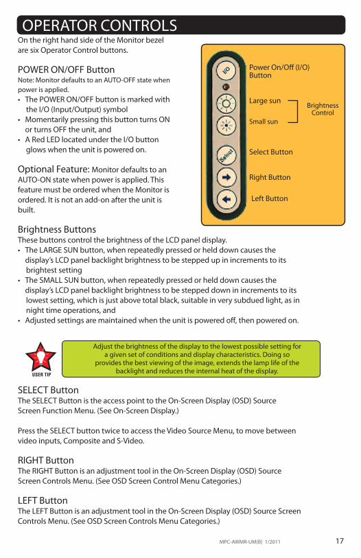
OPERATOR CONTROLSOn the right hand side of the Monitor bezel are six Operator Control buttons. POWER ON/OFF ButtonNote: Monitor defaults to an AUTO-OFF state whenpower is applied. • ThePOWERON/OFFbuttonismarkedwith
the I/O (Input/Output) symbol• MomentarilypressingthisbuttonturnsON or turns OFF the unit, and • ARedLEDlocatedundertheI/Obutton
glows when the unit is powered on.
Optional Feature: Monitor defaults to an AUTO-ON state when power is applied. This feature must be ordered when the Monitor is ordered. It is not an add-on after the unit is built.
Brightness ButtonsThese buttons control the brightness of the LCD panel display. • TheLARGESUNbutton,whenrepeatedlypressedorhelddowncausesthe display’s LCD panel backlight brightness to be stepped up in increments to its
brightest setting• TheSMALLSUNbutton,whenrepeatedlypressedorhelddowncausesthe display’s LCD panel backlight brightness to be stepped down in increments to its
lowest setting, which is just above total black, suitable in very subdued light, as in night time operations, and
• Adjustedsettingsaremaintainedwhentheunitispoweredoff,thenpoweredon.
SELECT ButtonThe SELECT Button is the access point to the On-Screen Display (OSD) Source Screen Function Menu. (See On-Screen Display.)
Press the SELECT button twice to access the Video Source Menu, to move betweenvideo inputs, Composite and S-Video.
RIGHT ButtonThe RIGHT Button is an adjustment tool in the On-Screen Display (OSD) Source Screen Controls Menu. (See OSD Screen Control Menu Categories.)
LEFT ButtonThe LEFT Button is an adjustment tool in the On-Screen Display (OSD) Source Screen Controls Menu. (See OSD Screen Controls Menu Categories.)
Adjust the brightness of the display to the lowest possible setting for a given set of conditions and display characteristics. Doing so
provides the best viewing of the image, extends the lamp life of the backlight and reduces the internal heat of the display.
Right Button
Left Button
Power On/Off (I/O) Button
Large sun
Select Button
Brightness Control
Small sun

18 MPC-AWMR-UM(B) 1/201118 MPC-AWMR-UM(B) 1/2011
ON-SCREEN DISPLAYThe On-Screen Display (OSD) user interface is the path to all display signal source adjustments. The Source Screen Menu, with its user-friendly graphical interface, provides access to fine-tuning the display. OSD Source Screen Menu ActivationTo activate the OSD menu in the current video source, press and release the SELECTbutton. Note: OSD Source Screen Menu closes after 15 seconds of inactivity. This setting can be adjusted in the OSD Source Screen Menu: Miscellaneous under OSD Duration.
OSD Source Screen Menu CategoriesThe Source Screen Menu is comprised of six icons, plus the Exit Door icon, each representing distinct source screen categories and their corresponding functions menu with adjustable settings.
General Instructions for Functions Menu Adjustments • ToopentheOSDSourceScreenMenu,press(once)theSELECTbutton•UsetheRIGHTorLEFTbuttontomoveacrosstheOSDSourceScreenMenuto
select the OSD Source Screen Display Category• AseachCategoryiconishighlighted,itsrelatedFunctionsMenuappearsinthe
lower section of the dialog box• ToactivateaDisplayCategory,withtheRIGHTorLEFTbuttonmovethehighlight
box over the Category’s icon • Press(once)theSELECTbuttontochoosethehighlightedicon• IntheFunctionsMenu,ahighlightbarissuperimposedoverthefirstfunction• PresstheRIGHTorLEFTbuttontomovethehighlightbarthroughthe related Functions Menu • Press(once)theSELECTbuttontoactivatethehighlightedFunctionsMenuitem• Createthenewvalue;adjustmentcontrolsaretheRIGHTandLEFTbuttons,which
increase or decrease the value of the parameter as indicated in the display bar• Press(once)theSELECTbuttontosavethenewvalue;thisreturnstheusertothe
display screen, or wait 15 seconds and the OSD will exit, saving all changes• TochooseanotherDisplayCategory,usetheRIGHTorLEFTbuttontomoveacross
the Source Screen Menu; repeat above instructions, or• UsetheRIGHTorLEFTbuttontomoveacrosstheOSDMenutohighlightthelast
icon, the Exit Door; press (once) the SELECT button to exit the OSD Menu• UponExit,allchangesaresaved.
• NewsettingsarestoredinmemoryuponpressingtheSELECTbuttontoexittheSource OSD Source Screen Category’s Function Menu
• IfSELECTisnotpressed,orinactivityisdetectedwithinthe15secondfactorydefault OSD duration, any function adjustments made will be saved.
CAUTION!
MPC-AWMR-UM(B) 1/2011 19MPC-AWMR-UM(B) 1/2011 19
It is recommended the LCD backlight brightness be aadjusted to maximum before fine-tuning the OSD Source Screen Menu Picture Menu Parameter: Brightness.
OSD Source Screen Menu Parameter Selections
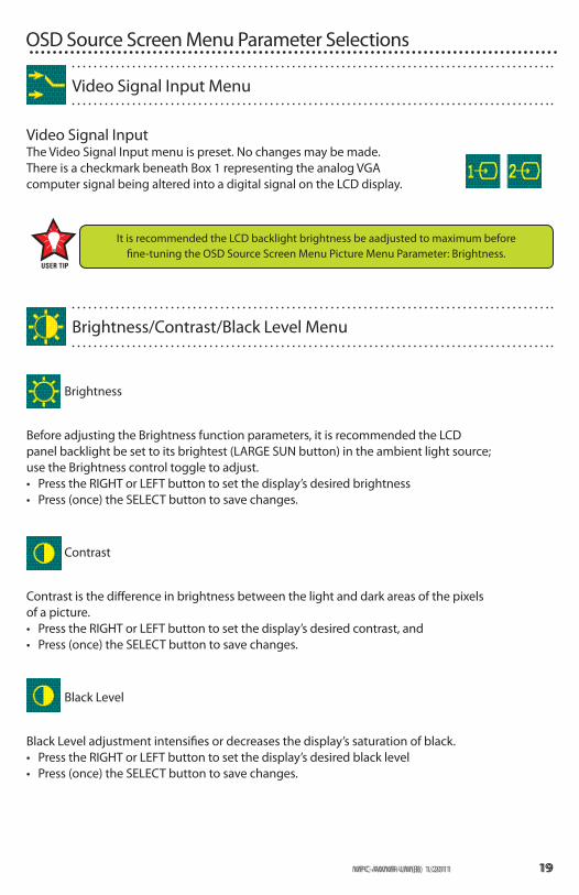
Video Signal Input The Video Signal Input menu is preset. No changes may be made. There is a checkmark beneath Box 1 representing the analog VGAcomputer signal being altered into a digital signal on the LCD display.
Video Signal Input Menu
Brightness
Before adjusting the Brightness function parameters, it is recommended the LCD panel backlight be set to its brightest (LARGE SUN button) in the ambient light source; use the Brightness control toggle to adjust.• PresstheRIGHTorLEFTbuttontosetthedisplay’sdesiredbrightness• Press(once)theSELECTbuttontosavechanges.
Contrast
Contrast is the difference in brightness between the light and dark areas of the pixelsof a picture.• PresstheRIGHTorLEFTbuttontosetthedisplay’sdesiredcontrast,and• Press(once)theSELECTbuttontosavechanges.
Black Level
Black Level adjustment intensifies or decreases the display’s saturation of black.• PresstheRIGHTorLEFTbuttontosetthedisplay’sdesiredblacklevel• Press(once)theSELECTbuttontosavechanges.
Brightness/Contrast/Black Level Menu
20 MPC-AWMR-UM(B) 1/2011
Color Adjustment Menu
Auto Color
• PresstheSELECTbuttontoruntheAutoColorSet-up.Notescreenflicker• Anewdialogboxpopsup,withhighlightedHappyandSadFaces• PresstheSELECTbuttontochoosetheHappyFaceifpresentAutoColorisaccept-
able or using LEFT button, choose the Sad Face if unacceptable, and• PresstheSELECTbuttontosavethechanges(ornotsaveifSadFacewaschosen)
and Exit.
Standard Color Set-up
•PresstheSELECTbuttontoallowtheOSDtoautomaticallysetStandardColor• AnewdialogboxpopsupwithhighlightedHappyandSadFaces•PresstheSELECTbuttontochoosetheHappyFaceifpresentAutoColorisaccept-
able or using LEFT button, choose the Sad Face if unacceptable, and• PresstheSELECTbuttontosavethechanges(ornotsaveifSadFacewaschosen)
and Exit.
RGB Color Temperature Settings (Color Adjustments)
•PresstheSELECTbuttontogototheRGB(Red,GreenBlue)ColorTemperature Settings Menu•UsetheRIGHTorLEFTbuttontoselectoneofthefiveTemperature settings• PresstheSELECTbuttontosavethechangesandExitorExitwithoutmaking
changes.
RGB Color Skin Tone Adjustment
•Bestaccomplishedifviewingascreenshotwithskintonepriortoadjusting•UsetheRIGHTorLEFTbuttontoadjusttheColorSkinTone• PresstheSELECTbuttontosavethechangesandExitorExitwithoutmaking
changes.
Audio Volume Adjustment is not available on this Monitor series.
Audio Volume Adjustment Menu
MPC-AWMR-UM(B) 1/2011 21
Image Setting Menu
Auto Configuration
•Foroptimaldisplayviewing,settoautoconfigurate.
Image Width
•PresstheRIGHTorLEFTbuttonto adjust the width•PresstheSELECTbuttontosaveandExitorExitwithoutmakingchanges.
Phase Adjustments
•PresstheRIGHTorLEFTbuttonto adjust the signal phase in the analog to digital converter•PresstheSELECTbuttontosaveandExitorExitwithoutmakingchanges.
H-Position
• PresstheRIGHTorLEFTbuttontoadjusthorizontalpositionofthedisplay•PresstheSELECTbuttontosaveandExitorExitwithoutmakingchanges.
RGB Color Saturation Adjustment
Saturation is the vividness or intensity of the hue or color.• PresstheRIGHTorLEFTbuttontosetthedisplay’sdesiredsaturation• PresstheSELECTbuttontosavethechangesandExitorExitwithoutmaking
changes.
RGB Color Hue Adjustment
Hue is the pinks, blues and greens of the display.• UsetheRIGHTorLEFTbuttontoadjust• PresstheSELECTbuttontosavethechangesandExitorExitwithoutmaking
changes.

22 MPC-AWMR-UM(B) 1/2011
OSD Duration
• PresstheRIGHTorLEFTbuttontoadjustthetimeelapsebetweenthelastmenuactivity and when the menu disappears. Factory default is 15 seconds
•PresstheSELECTbuttontosaveandExitorExitwithoutmakingchanges.
OSD H-Position
• PresstheRIGHTorLEFTbuttontoadjustthehorizontalpositionoftheOSDmenuon the display
•PresstheSELECTbuttontosaveandExitorExitwithoutmakingchanges.
OSD V-Position
• PresstheRIGHTorLEFTbuttontoadjusttheverticalpositionoftheOSDmenuonthe display
•PresstheSELECTbuttontosaveandExitorExitwithoutmakingchanges.
OSD Screen Zoom Setting
•PresstheSELECTbuttontoenableOSDdialogboxZoomfeature•PresstheRIGHTbuttontogotoExit•PresstheSELECTbuttontosaveandExitorExitwithoutmakingchanges.
Factory Reset
•PresstheSELECTbuttontoExitandreturnallOSDusersettingstofactorydefault.
Miscellaneous - OSD Dialog Box Control
V-Position
• PresstheRIGHTorLEFTbuttontoadjusttheverticalpositionofthe display•PresstheSELECTbuttontosaveandExitorExitwithoutmakingchanges.

MPC-AWMR-UM(B) 1/2011 23
OPTIONAL USB CONNECTOR
Optional USB ConnectorThe optional USB Connector is located on the rear panel pod. It does not alter thewater-tight design of the monitor. The unit remains sealed.

24 MPC-AWMR-UM(B) 1/2011
OPTIONAL TOUCH SCREENMPC-AWMRL Optional Touch Screen Installation
If you are installing a new operating system (O/S), do not install the Touch Screen Controller Driver CD until you have installed the O/S and verified the computer’s monitor display is working properly. The Touch Screen Controller Driver uses the computer’s O/S display driver software settings to accurately configure the Touch Screen Controller Driver files.
Previous Versions of Touch Screen Controller Drivers
Previous versions of ANY Touch Screen Controller Driver must be removed before installing the latest version of the TSHARC™ Touch Screen Controller Driver.
Uninstall a Previous Version of TSHARCThe uninstall utility “TSUN10.exe” is included on the TSHARC Touch Screen Con-troller Installation CD, in the shipping box with the product accessories. This utility uninstalls TSHARC drivers only.
From the Product CD To uninstall: install the CD > go to My Computer (desktop) > Left double mouse click > Locate the drive with the Installation CD > Left mouse click to open > Left double mouse click on the Uninstall Drivers folder > Left double mouse click on “TSUN10.exe” to execute the uninstall utility > Follow the instructions.
Note: The dialog box stating it is removing all Touch Screen Drivers from the computer means it is removing all TSHARC drivers. Other Touch Screen Drivers must be uninstalled with their manufacturer’s uninstall utility.
From the MarinePC Web SiteThe TSHARC uninstall utility may be down-load from www.marinepc.com. Go to the Support tab > Downloads > Uninstall TSHARC Drivers > TSUN10.exe.
To download the utility, left double mouse click on the file name > At the File Down-load dialog box, select Save > Save the file to the computer’s program files > Make a new folder, “TSHARC Uninstall” > Select Open > Save the TSUN10.exe file > At the dialog box “Download is complete”, select Open Folder > Left double mouse click on “TSUN10.exe” to execute the utility > At the dialog box “Do you want to remove”,selectYes>Atthedialogbox“PressOKtocompletetheuninstall”,selectOK>Attheuninstallconfirmationscreen,selectOK.Followtheinstructions.
Note: The dialog box stating it is removing all Touch Screen Drivers from the computer means it is removing all TSHARC drivers. Other Touch Screen Drivers must be uninstalled with their manufacturer’s uninstall utility.
Uninstall TSHARC Utility
CAUTION!
CAUTION!

MPC-AWMR-UM(B) 1/2011 25
Uninstall a Previous Version of Other Touch Screen Drivers If a version of a different Touch Screen Controller Driver (not TSHARC) is on the com-puter, it must be completely removed before installing the TSHARC. Note: The typical driver uninstall program or Microsoft’s® remove program utility does not remove all tracks of the Touch Screen Driver program. Contact the manufacturer of the previ-ously installed driver program to learn how to completely uninstall their product. These instructions may be available from the manufacturer’s web site.
Installation1. Attach the Touch Screen Cable connector to the MPC_AWMRL 4-pin connector2. Attach the Touch Screen Cable RS-232 connector to a computer serial port, or3. Attach the Touch Screen Cable USB connector to a computer USB port.
Note: For Multi-monitor applications, all Touch Screens must be connected to the computer before installing the TSHARC driver.
• IfinstallingRS-232connectors,thedriverhastobeinstalledfor each Touch Screen, or
• IfinstallingUSBconnectors,thedriverisinstalledonetimefor multiple Touch Screens.
• IftheTouchScreenconnectorisUSB,Windowshallloadatemporary USB driver. Wait for the driver to load.
1. Boot up the computer2. Insert the TSHARC Controller Driver CD3. On the desktop, left double mouse click on
the My Computer icon4. Locate the drive with the TSHARC Touch
Screen Controller Drivers Installation CD5. Left mouse click to open6. Left mouse double click to open the Resistive
Touch Driver file7. Left mouse double click to open the file for
2000, XP, 98, ME O/S, and8. Left mouse double click to run “set-up.exe”.
Touch Screen Installation
Before loading Touch Screen Controller drivers, verify the COM ports are enabled (especially if using a laptop computer).CAUTION!
CAUTION!
TSHARC Touch Screen Controller DriverA TSHARC Touch Screen Controller Installation CD is included in the shipping box with the product accessories. The driver is compatible with these O/S: Windows® 98 SE (Second Edition), ME, 2000, XP, Vista and Windows7.

26 MPC-AWMR-UM(B) 1/2011
1. At the Welcome screen, select Next to go to the Software License Agreement (EULA)
2. After reading the EULA, if in agreement, check the box “I accept all of the terms…”
3. Select Next.
Note: Any unlawful use of the TSHARC driver is a strictviolation of the United States and International copyright laws. Using a TSHARC driver with any third party TouchScreen is strictly prohibited.
TSHARC Installation
If you need to cancel this driver installation at any time, select the Cancel button on the driver installation dialog screen.
Select Controller 1. The TSHARC Driver is a 12-bit controller; the radio button is selected by defaultNote: A PS/2 controller interface is not available.2. Select the controller interface matching the cable
used to install the MPC-AWMRL3. Select the Autodetect button if installing the Touch
Screen through a RS-232 (serial) interface
4. There are two options for RS-232 installation: Auto-detect and Manual. Manual instructions are found in section Manual RS-232 Controller Set-up
5. If connecting through a USB interface, select the USB radio button
6. Select Next 7. Following installation, select Finish, and8. Reboot the computer when prompted.
Autodetect RS-232 Controller Set-up1. Select the Autodetect button2. The “AutoDetect Serial” dialog box lists the detected
RS-232controllerinformation.SelectOK3. “Installing Touch Screen Driver” text box pops up,
indicating the progress of the installation4. Following installation, select Finish, and5. Reboot the computer when prompted.
CAUTION!
MPC-AWMR-UM(B) 1/2011 27
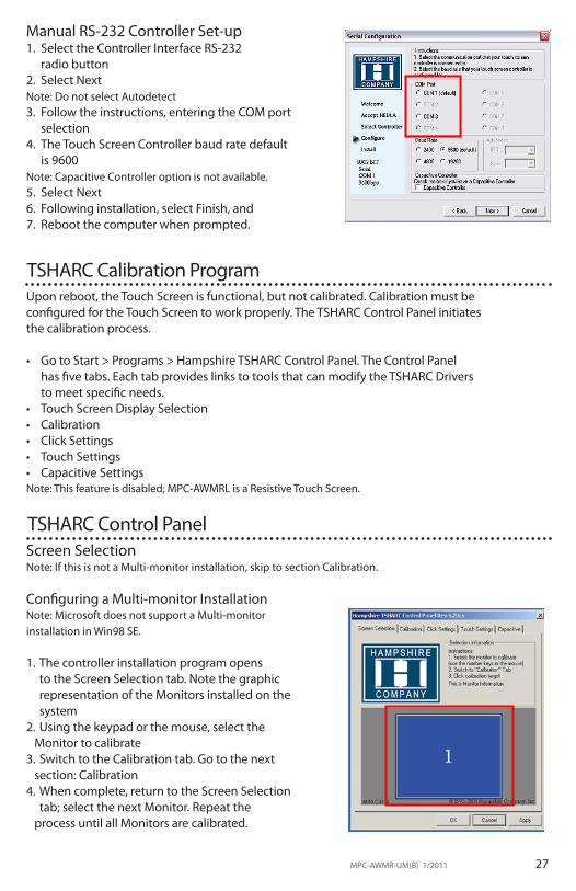
Manual RS-232 Controller Set-up1. Select the Controller Interface RS-232
radio button2. Select NextNote: Do not select Autodetect3. Follow the instructions, entering the COM port
selection4. The Touch Screen Controller baud rate default
is 9600Note: Capacitive Controller option is not available. 5. Select Next6. Following installation, select Finish, and7. Reboot the computer when prompted.
Upon reboot, the Touch Screen is functional, but not calibrated. Calibration must be configured for the Touch Screen to work properly. The TSHARC Control Panel initiatesthe calibration process.
• GotoStart>Programs>HampshireTSHARCControlPanel.TheControlPanelhas five tabs. Each tab provides links to tools that can modify the TSHARC Drivers to meet specific needs.
• TouchScreenDisplaySelection• Calibration• ClickSettings• TouchSettings• CapacitiveSettingsNote: This feature is disabled; MPC-AWMRL is a Resistive Touch Screen.
TSHARC Calibration Program
TSHARC Control PanelScreen SelectionNote: If this is not a Multi-monitor installation, skip to section Calibration.
Configuring a Multi-monitor InstallationNote: Microsoft does not support a Multi-monitor installation in Win98 SE.
1. The controller installation program opens to the Screen Selection tab. Note the graphic representation of the Monitors installed on the system
2. Using the keypad or the mouse, select the Monitor to calibrate3. Switch to the Calibration tab. Go to the next section: Calibration 4. When complete, return to the Screen Selection
tab; select the next Monitor. Repeat the process until all Monitors are calibrated.

28 MPC-AWMR-UM(B) 1/2011
Calibration The calibration process aligns the Touch Screen overlayto specific points on the Display screen.
1. Select the Calibration tab or, in ten seconds, the calibration program launches, unless a Multi-monitor situation is present, then go to section Configuring a Multi-monitor Installation
2. There are three buttons: Graphic, Calibration and Test. For default Four-point calibration, select the Graphic square. This is the best known general
calibration; it compensates for skew and some edge linearity anomalies, and
3. Go to section Calibration Process.
Custom Calibration Settings1. To customize the calibration process, select the Calibration button to bring up
Calibration Options and the Offset menu2. SelectOKwhencalibrationand/oroffsetselections
are made:• Three-PointCalibration:Quickcalibrationofa
known good Touch Screen overlay. No correc-tion is applied
• Four-PointCalibration:Compensatesforskewand some edge linearity anomalies
• Seven-PointCalibration:Moreaccuratethanthree-point calibration. No correction is applied
• Twenty-PointCalibration:Providesthehighestlevel of Touch Screen linearization and skew cor-rection, and
• Offset:VariedlinearityexistsbetweenTouchScreen types; user may want to calibrate the edges of the Touch Screen more precisely. Default is 20%.
Calibration Process1. Press the Center Graphic to start calibration2. Targets are used to calibrate the Touch Screen. Follow
the on-screen instructions - “Touch” the target center, “hold” until it shrinks, then “release” the target, and
3. Repeat the process for all targets. Note: the calibration screen shall time-out and return to the Calibration tab if the first point is not touched within 10 seconds.
Calibration Verification Test1. Touch the screen in several places to verify the calibration target is displayed under the finger, and2. Select the Accept button to apply and record the calibration data. Note: If the calibration target is not displayed under the finger, select the Cancel button, repeat Custom Calibration Settings, then Calibration Process.

MPC-AWMR-UM(B) 1/2011 29
Calibration Drawing Test1. Select the Test button on the Calibration tab2. Using a finger or stylus, draw or write, and3. Observe if the screen displays the drawing accu-
rately. If it does not, repeat the Custom Calibration Settings and Calibration Process instructions
Click SettingsRight Click1. If desirable for Touch Screen application, check the
“Enable Right Click” box to set the right click option
Right Click Area2. Use the slide bar to set the Touch Screen event area to a size slightly larger than the activator – larger for a finger tip, smaller for a stylus; the box displays the activator size
Right Click DelayThe timed-hold right click mouse event allows theuser to initiate a right click by holding down a touchpoint for a specific period of time. 3. Use the slide bar to set the Right Click Delay value to the time necessary to produce a right click event
Double Click AreaThis step sets the area that shall allow for a double click event. Limit this to areas that can be accurately touched several times.4. Use the slide bar to set the double click area; the box displays the activator size
Double Click Speed5. Usetheslidebartosetsufficienttimetoperformadoubletouchinthespecified
area6. Select the Apply button to enter the selection, and7. SelecttheOKbuttontoapplyallClickSettings.
Touch Settings1. Normal: Emulates a standard mouse, allowing a
single click, double click, drawing, dragging and right click option (if enabled)
2. Touch Down: Allows for a click event to take place at touch down. No draw or drag is available
3. Touch Up: Touch only. Double click is disabled. If right click was earlier enabled, it shall be disabled.
Touch Sound1. Check the Enable Touch Sound to enable a tonal
beep when the screen is touched2. Select the Apply button to enter the selection, and3. SelecttheOKbuttontoapplyallTouchSettings.

30 MPC-AWMR-UM(B) 1/2011
Capacitive Tab – DisabledThe Touch Screen is a resistive type; the Capacitive Tab shall be disabled.
Touch Screen Tray Icon1. If you do not want a Touch Screen Controller Icon to
display in the toolbar tray, go to step 3, or2. If you want a Touch Screen Controller Icon to display
in the toolbar tray, select the box, and3. Select the Finish button; the TSHARC drivers shall be
installed.
Installation Complete 1. At the dialog box, “Setup is now complete”,
selectOK,exitingtheTSHARCTouchScreen Controller installation
2. Congratulations! The MPC-AWMRL Touch Screen is ready to go to work.
MPC-AWMR-UM(B) 1/2011 31
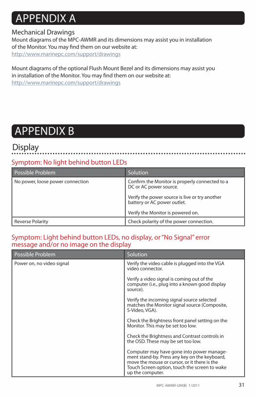
Mechanical DrawingsMount diagrams of the MPC-AWMR and its dimensions may assist you in installation of the Monitor. You may find them on our website at:http://www.marinepc.com/support/drawings
Mount diagrams of the optional Flush Mount Bezel and its dimensions may assist you in installation of the Monitor. You may find them on our website at:http://www.marinepc.com/support/drawings
APPENDIX A
APPENDIX B
Symptom: No light behind button LEDsPossible Problem SolutionNo power, loose power connection Confirm the Monitor is properly connected to a
DC or AC power source. Verify the power source is live or try another battery or AC power outlet.
Verify the Monitor is powered on.
Reverse Polarity Check polarity of the power connection.
Symptom: Light behind button LEDs, no display, or “No Signal” error message and/or no image on the display
Possible Problem SolutionPower on, no video signal Verify the video cable is plugged into the VGA
video connector.
Verify a video signal is coming out of the computer (i.e., plug into a known good display source).
Verify the incoming signal source selected matches the Monitor signal source (Composite, S-Video, VGA).
Check the Brightness front panel setting on the Monitor. This may be set too low.
Check the Brightness and Contrast controls in the OSD. These may be set too low.
Computer may have gone into power manage-ment stand-by. Press any key on the keyboard, move the mouse or cursor, or it there is the Touch Screen option, touch the screen to wake up the computer.
Display

32 MPC-AWMR-UM(B) 1/2011
Symptom: Display has rolling “bars” across the screen or vertical shaded bars on the image.
Possible Problem SolutionVGA video display is not set to view at 800 x 600 pixels, or 1024x768 pixels.
Verify the computer video display settings of the signal are set to match the display and 60 Hz refresh rate.
Defective video cable On a known good display source, confirm the video cable is not defective.
Interference from adjacent equipment For proper grounding and shielding, verify use of a proper video cable.
KeepthecableawayfromsourcesofEMIsuch as electric motors, or unshielded RFsources such as radar and microwave.
Horizontal size is not adjusted In the OSD, adjust the horizontal size controls.
Symptom: Picture quality, image stability is distorted.Possible Problem SolutionNot working in 800 x 600 or 1024x768 pixel resolution
Press the arrow down button one time to auto adjust the display.
Verify the video display settings match the monitor, and 60 Hz refresh rate.
Proper cable grounding and shielding Verify the use of a proper video cable with suitablegroundingandshielding.Keepthevideo cable away from sources of EMI and RF.
Improper video display settings Check signal source for proper signal. Check for proper display properties selection of the display pixel setting. Verify the display refresh rate: 60 Hz.
Display unit is farther than 3 m (10 ft) from signal source
Single cable lengths in excess of the standard 3 m (10 ft) cable should be of high quality shielded VGA cable. Contact MarinePC for information on custom cables.
Multiple Monitors are driven from the same signal source.
Splitting the video signal divides the strength of the signal. A video signal booster (line driver) is recommended if installation requires more than one Monitor driven from a single video source.
Monitor has incorrect or bad sync signals. Check for proper video cable installation, or replace suspected faulty cable.
Check the video source is within the display’s oper-ating range: max. 1280x1024 pixels, and 60 Hz.

MPC-AWMR-UM(B) 1/2011 33
Symptom: Display image is not properly sizedPossible Problem SolutionOSD adjustments need to be made Adjust the vertical and horizontal size controls
through the OSD.
Improper video display settings Check for proper display properties selection of the display settings. Monitor autosize will only display full screen if source is 4:3 aspect ratio.
VGA signal source “Auto Adjust” needs activated
The VGA source is able to auto adjust the Monitor to its optimum viewing setting. Press the arrow down button one time to auto adjust the display.
Possible Problem SolutionT/S cable is not plugged in Verify the connections between the T/S and
the computer.
T/S cable is installed in a different COM port than installed by the software
Install the T/S into another COM port. If using a laptop, verify the COM port(s) is enabled.
T/S controller driver has not been installed Install the TSHARC controller driver.
Hardware failure Contact a MarinePC Technical Support Techni-cian (480.515.1838).
Symptom: Touch Screen (T/S) does not respond
Symptom: T/S moves, but does not follow a finger or stylusPossible Problem SolutionController is not calibrated Run the calibration in the TSHARC Control
Panel software.
T/S Controller Driver is not installed Install the TSHARC Controller Driver.
T/S cable is not installed correctly Verify the T/S cable is installed correctly.
Symptom: “Error in Calibration” message appearsPossible Problem SolutionThe T/S Controller Driver is not installed correctly
Uninstall the driver using “TSUN10.exe”. If a previous T/S Controller Driver was installed, all footprints must be removed. Go to the T/S manufacturer’s web site or contact the manu-facturer for instructions to uninstall drivers.
Reinstall the TSHARC Driver software.

34 MPC-AWMR-UM(B) 1/2011
APPENDIX CTechnical Specifications
8.4” 10.1” 12.1” 15.1”
Display TFTAM,SVGA,LCD,256KColors. 800 x 600 pixels
12M Colors,
1024 x 768 pixels
Sunlight Readable 1,000 nits, AR/AG
Dimming Ratio 1,000:1
Video Input VGA
Connectors
IP67 Fischer High Density to DB-15 JAE to Flying leads DC Input JAE to DB-9 Touch (optional) JAE to USB Port (optional)
Housing Milled Aluminum, Black Anodized, UV Clear Coat
Mounting Panel Mount or RAM Mount
Power Consumption 6 Watts Min - 15 Watts Max 16 Watts Max 17 Watts Max 35 Watts Max
Wide Range DC Power
Input
8-30 VDC
(12, 24, 28 VDC nominal)
Power Conditioning
Internal Short Circuit Protection Load Dump Protection Over Voltage Protection Reverse Polarity Protection

MPC-AWMR-UM(B) 1/2011 35
Environmental Specifications8.4” 10.1” 12.1” 15.1”
Operating Temperature -40°C to 70°C (-40°F to 158°F)
Storage Temperature -40°C to 75°C (-40°F to 167°F)
Shock 50 G
Vibration 5.8 G (5-500 Hz)
IP Rating IP67 (NEMA 6P Submersible)
Humidity 0-100%
EMI Designed to meet FCC B, CE
Altitude 45,000 ft.
PUM 0504 AWMVR(B) 1/2011
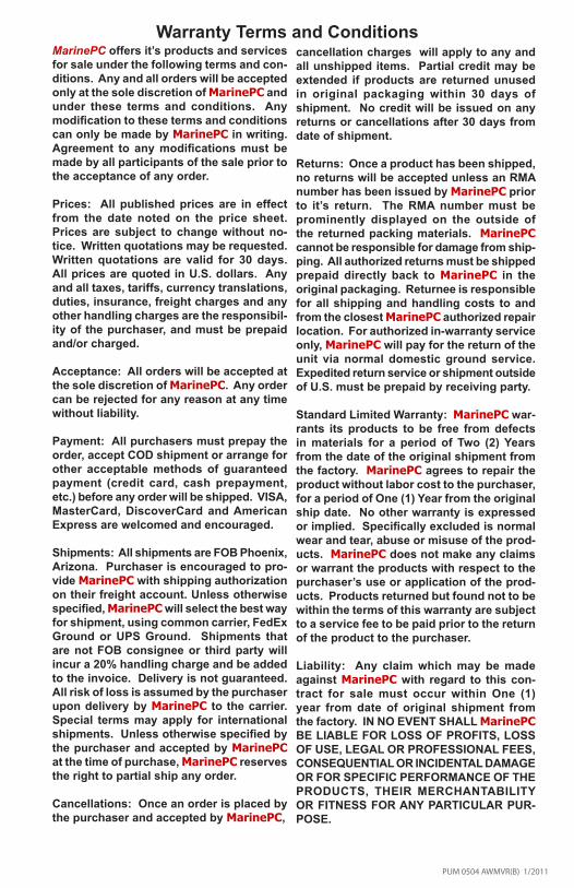
Warranty Terms and ConditionsMarinePC offers it’s products and services for sale under the following terms and con-ditions. Any and all orders will be accepted only at the sole discretion of MarinePC and under these terms and conditions. Any modification to these terms and conditions can only be made by MarinePC in writing. Agreement to any modifications must be made by all participants of the sale prior to the acceptance of any order.
Prices: All published prices are in effect from the date noted on the price sheet. Prices are subject to change without no-tice. Written quotations may be requested. Written quotations are valid for 30 days. All prices are quoted in U.S. dollars. Any and all taxes, tariffs, currency translations, duties, insurance, freight charges and any other handling charges are the responsibil-ity of the purchaser, and must be prepaid and/or charged.
Acceptance: All orders will be accepted at the sole discretion of MarinePC. Any order can be rejected for any reason at any time without liability.
Payment: All purchasers must prepay the order, accept COD shipment or arrange for other acceptable methods of guaranteed payment (credit card, cash prepayment, etc.) before any order will be shipped. VISA, MasterCard, DiscoverCard and American Express are welcomed and encouraged.
Shipments: All shipments are FOB Phoenix, Arizona. Purchaser is encouraged to pro-vide MarinePC with shipping authorization on their freight account. Unless otherwise specified, MarinePC will select the best way for shipment, using common carrier, FedEx Ground or UPS Ground. Shipments that are not FOB consignee or third party will incur a 20% handling charge and be added to the invoice. Delivery is not guaranteed. All risk of loss is assumed by the purchaser upon delivery by MarinePC to the carrier. Special terms may apply for international shipments. Unless otherwise specified by the purchaser and accepted by MarinePC at the time of purchase, MarinePC reserves the right to partial ship any order.
Cancellations: Once an order is placed by the purchaser and accepted by MarinePC,
cancellation charges will apply to any and all unshipped items. Partial credit may be extended if products are returned unused in original packaging within 30 days of shipment. No credit will be issued on any returns or cancellations after 30 days from date of shipment.
Returns: Once a product has been shipped, no returns will be accepted unless an RMA number has been issued by MarinePC prior to it’s return. The RMA number must be prominently displayed on the outside of the returned packing materials. MarinePC cannot be responsible for damage from ship-ping. All authorized returns must be shipped prepaid directly back to MarinePC in the original packaging. Returnee is responsible for all shipping and handling costs to and from the closest MarinePC authorized repair location. For authorized in-warranty service only, MarinePC will pay for the return of the unit via normal domestic ground service. Expedited return service or shipment outside of U.S. must be prepaid by receiving party.
Standard Limited Warranty: MarinePC war-rants its products to be free from defects in materials for a period of Two (2) Years from the date of the original shipment from the factory. MarinePC agrees to repair the product without labor cost to the purchaser, for a period of One (1) Year from the original ship date. No other warranty is expressed or implied. Specifically excluded is normal wear and tear, abuse or misuse of the prod-ucts. MarinePC does not make any claims or warrant the products with respect to the purchaser’s use or application of the prod-ucts. Products returned but found not to be within the terms of this warranty are subject to a service fee to be paid prior to the return of the product to the purchaser.
Liability: Any claim which may be made against MarinePC with regard to this con-tract for sale must occur within One (1) year from date of original shipment from the factory. IN NO EVENT SHALL MarinePC BE LIABLE FOR LOSS OF PROFITS, LOSS OF USE, LEGAL OR PROFESSIONAL FEES, CONSEQUENTIAL OR INCIDENTAL DAMAGE OR FOR SPECIFIC PERFORMANCE OF THE PRODUCTS, THEIR MERCHANTABILITY OR FITNESS FOR ANY PARTICULAR PUR-POSE.