s! - defense technical information center. s. army mobility equipment research and dzvelopment...
TRANSCRIPT

S!
1t~ ADI
Report 2024
___• BIDIRECTIONAL METER USED FOR VOLUMETRICMEASUREMENT OF MILITARY-STANDARD HYDROCARBON
LIQUID FUELS AT BULK STORAGE INSTALLATIONS
by
Joe Medrano
February 1972
Approved for public reledse; distribution unlimited.Reproduced by
NATIONAL TECHNICALINFORMATION SERVICE
SP gfroIld, Va 22151
U. S. ARMY MOBILiTY EQUIPMENT RESEARCH AND DEVELOPMENT CENTERFORT BELVOIR, VIRGINIA
,D DDCmnnA
r 01111 28 1972

Destroy this reporl. %hen no longer needed. Do not return it to the originator.
The citation in this report of trade names ol" commercially evailable products doesnot constitute official endorsement or approval of the use of such products.
,',iE SECTION >• -uICOUFF UT• $ E C 3
" "..*... .... . °.. ..
-. 1 --.... ... ... .... ...
;/jM AVAIL a*#W

UNCLASSIFIEDsecallty OsafC11141
DOUME14T CONTROL DATA.- R & D(S~e9Ufy 4:04101aatflaej 0! tool.. body1 ebae,."a -inxg 410000640 mostm asI beuld Iha 000.,raulrdouest I ~.
I- ORIGINATING ACTIVITY (Cedopw~aue on) XSO. REPORT SE.;URITY CLASSIFICATION
U. S. Army Mobility Equipment Research and Development Center UnclassifiedFort Belvoir, Virginia20GRU
8. REPORT TITLE
BIDIRECTIONAL METER USED FOR VOLUMETRIC MEASUREMENT OF MILITARY-STANDARDHYDROCARBON LIQUID FUELS AT BULK STORAGE INSTALLATIONS
5. DSCRIPTIVEt NOTES (rNPo 0SVI anu Sd facami,. doft.)
Ewngiern vlainRp - March 1968 to May 1969LAU THORI51 (Filet ASS1o. MInCAN blifieU. lao asmos)
Joe Medrano,
6. REPORT DATE 7a. TOTAL NO0. OF PAGES 7b. No. Oll MCE's
February 1972 321OI. CONTRACT OR IIRANT NO. 0.ORIGINATORS REPORT NUIWISRIS)
L. PROJECT No. 2024IJ664717DL41____________ _____
Task J66417DL411 S. OlTHER RM.CORT NO(S) (Afy 0111IMINbeAN, dial my be Ma.Idw
1 1. OISTRIGUTION
STATEMENT
Approved for public release; distribution unlimited.
II.~Ful SUPLEENTRYNOTS Equipment Division
____________ ________________Fort BeivoiVrna 22060
This report cov.crs the testing and evaluation of a bidirectional vortex velocity meter to determine itssuitability for -"olumetric measurement of liquid hydrocarbon fuels in conjunction with the operation of10,000- and 25,0,0.barrel hasty storage - servoirs.
A Rotron, 4-in., vortey.vp~locity meter with a uringe of flow from 200- to 1250.gpm was installed atUSAMERbC test facilities and fuel was pumped through the meter in forward and reverse directions offlow to determine the accuracy. The overall accuracy obtained 1% as within the desired ± 1 -percent limitw'th a repeatability of ±0.1 percent of meter readings when operating within the meter linear range.
AEPLACES 00 FORM 1472. 1 JAN 0.WHICN IS
DD PM 0647 OSI9 OSEETE Von ARMY VSE. 31 UNCLASSIFIED3 Uscuwtty Classification

UNCLASSIFIEDSeci Curiylaslitkuoa
14. LINK A I.INK . LINK CKIEV WORDS ,
ROLE !T "' LE WI ROLI WT
Petroleum Products 1Bidirectional FlowmetersVolumetric Flowmc:ersFuels Handling Storage FacilitiesPipeline System Storage
32 t N(CLASSIFIEDSecuity Chlusinscat on

U. S. ARMY MOBILITY EQUIPMENTRESEARCH AND DZVELOPMENT CENTER
FORT BELVOIR, VIRGINIA
Report 2024
BIDIRECTIONAL METER USED FOR VOLUMETRICMEASUREMENT OF MILITARY-STANDARD HYDROCARBON
LIQUID FUELS AT BULK STORAGE INSTALLATIONS
Task 1J664717DL4111
February 1972
Distributed by
The Commanding OfficerU. S. Army Mobility Equipment Research and Development Center
Prepared by
Joe MedranoFuels Handling Equipment DivisionMechanical Technology Dcpartment
Approved f(or public release: distribution unhlmited.'I

SUMMARY
This rep(,,-t covers the testing and evaluation of a bidirectional vortex-velocity me-ter to determine its suitability for volumetric measurement of liquid hydrocarbon fuelin conjunction with the operation of 10,000- and 25,000-barrel hasty-storage reservoirs.
A Rotron, 4-in., vortex-velocity meter with a range of flow "rom 200 to 1250 gpmwas installed at USAMERDC Test Facility, and fuel was pumped through the meter inforward and reverse directions of flow to determine its accuracy. The overall accuracyobtained was within the desired ± 1-percent limit with a repeatability of ± 0.1 perceniof meter readings when operating within the meter's linear range.

t
FOREWORD
The testing and evaluation covered by this report was conducted under the generalauthority of Project 1J664717DL41, POL Distribution Systems. The work was acrom-plished in conformance with ipecific requirements of Task 1J664717DL41 11, BulkFuel Storage.
The period covered is March 1968 through May 1969.
This project was undef the general supervision of John D. Grabski, Chief, FuelsHandling Equipment Division, and under the direct supervision of N. A. Caspero, Chief,Onshore Fuel Systems Branch.
The follo;,ig personnel participated in th2 test program: James Christopher,Equipment Specialist; Warren Parrish, Test Leadman; Richard Clement and RobertCasteel, T'1st Mechanics.
fii
CONTENTS
Section Title Page
SUMMARY '
FOREWORD i
ILLUSTR ATIONS
TABLE v
I INTRODUC MIN
2. Opcrationi1 Requiremnent 1
1I INVESTIGAh(JN
3. Type (,f Meter lnvest.,ýa',d 14. Description of Meter 25. Decito of Test 36. Results GfTcsts 3
III DISCUSSION AND EVALUATION
7. Analysis of Defic, encies
8. Evaluatiun of Equipment i
IV COCUIONS
9. Condlusiom (2
APPENDIX - Purchvasu 'Pescrip,.Olo13

ILLUSTRATIONS
Figure Title Page
1 Meter Flow Pattern 2
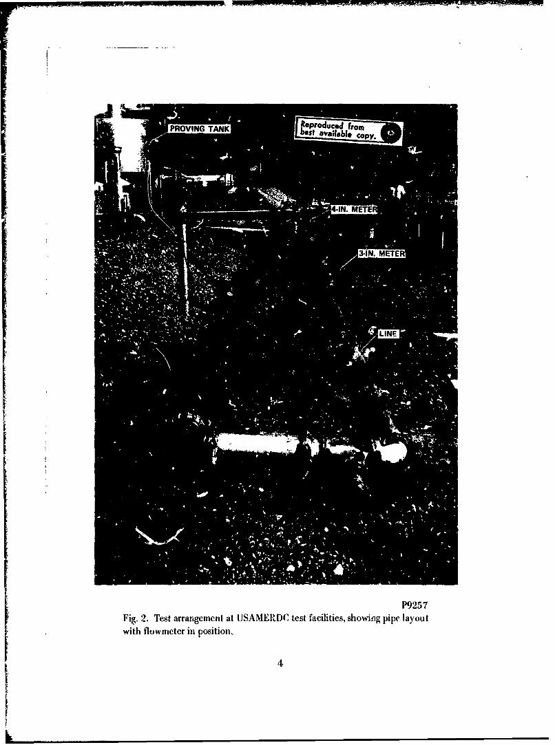
2 Test Arrangement at I. SAMERDC Test Facilities, ShowingPipe Layout with .:!wmeter in Position 4
"3 Test Arrangement at USAMERDC Test Facilities, ShowingFlowmeter and Test Monometer 5
4 A I-In. and 3-In. Meter Calibration Test Setup 6
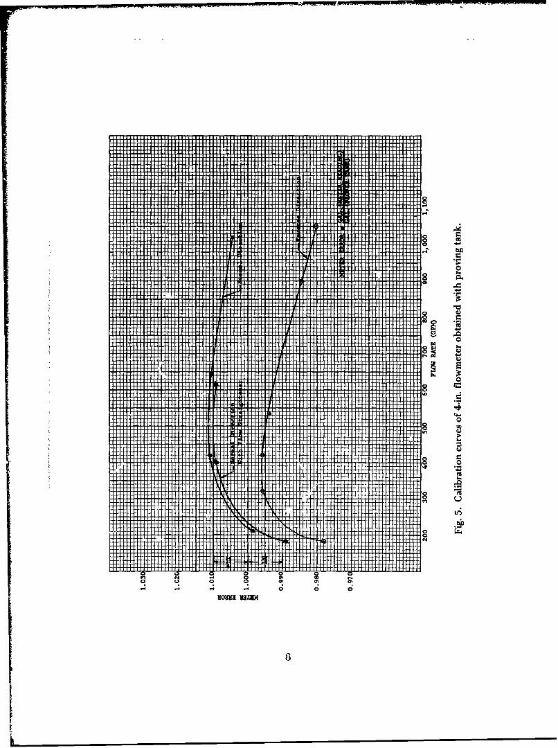
5 Calibration Curves of 4-In. Flowmeter Obtained with ProvingTank 8
6 Catibration Curves of 3-In. and 4-in. Flowmeters Obtainedwith Proving Tank
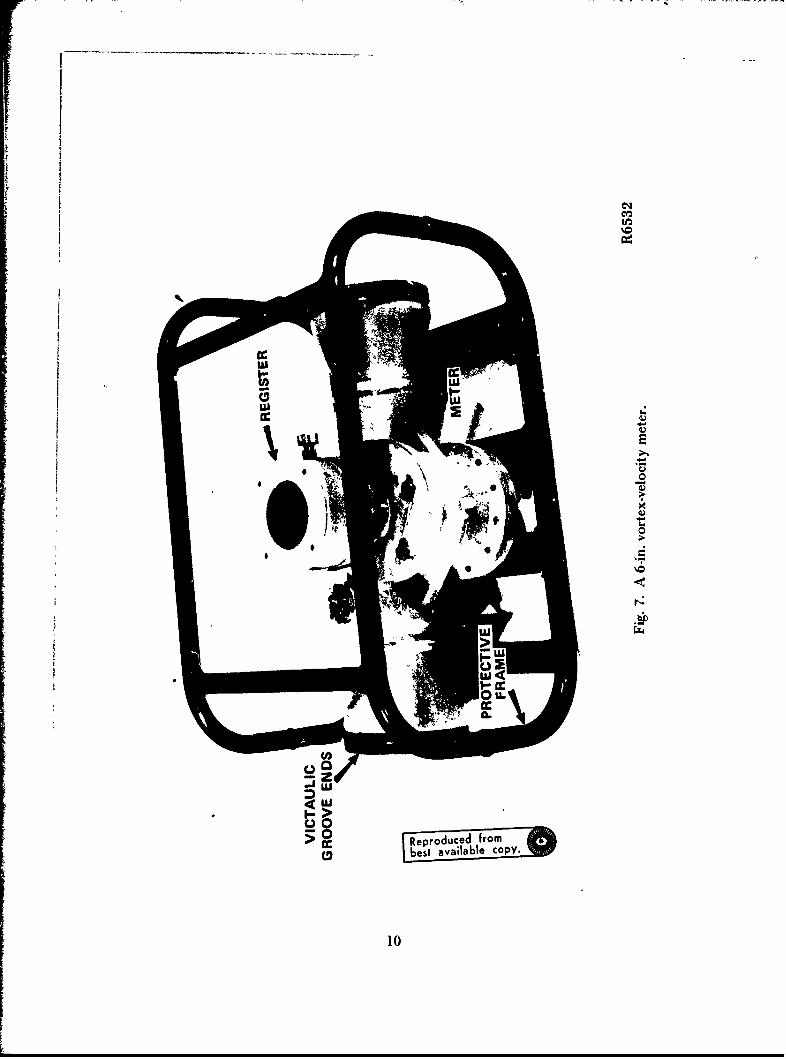
7 A 6-In, Vortex-Velocity Meter 10
8 Flowmeter Assembly 11
TABLE
Title Page
Sizes of Rotron Bidirectional Flowmeters 12
I

BIDIRECTIONAL METER USED FOR VOLUMETRICMEASUREMENT OF MILITARY-STANDARD HYDROCARBON
LIQUID FUELS AT BULK STORAGE INSTALLATIONS
I. INTRODUCTION
1. Subject. This report describes the testing and evaluation of a bidirectional-type flowmeter used for volumetric measurements of military-standard hydrocarbonliquid fuels at bulk storage tank installations.
2. Operational Requirement. A requirement exists for a volumetric measuringmeter which would be suitable for operation in the 8-in. pipeline used to fill and drainft el from the 10,000-barrel and 25,000-barrel hasty-fuel-storage reservoirs. The meteris to be capable of operating satisfactorily in normal and reverse directions of flowwhen installed in the pipeline, without requiring bypassing or looping, or without re-quiring change of meter parts or reversal of the meter in the pipeline. Since the hasty-
fuel-storage reservoirs are installed in earthen pits, each having different nonuniform
dimensions, the quantity of fuel in the reservoirs is difficult to determine by conven-tional methods of gaging, and a meter is necessary to keep an accurate account.
II. INVESTIGATION
3. Type of Meter Inveitigatel. The most suitable meter for Army field usewould be a flowmeter (!.e., positive displacement, turbine, electromagnetic, orifice,etc.) meeting the followiilg requiremen:.'t, some of which are described more fully inthe appendix to this rej-'rt.':
a. Linear rangeability.b. Repeatability.c. Meter reproducibility.d. Insensitivity to viscosIty.e. Meter factor adjustment.f. Meter factor consistency.,g. Compatibility to fluid.h. Tife of moving parts.i. Readout restrictions.j. Ease of maintepance.
With these features in mind, a vortex meter was selected and evaluated atthe U. S. Army Mobility Equipment Research and Developme.it Center (USAMEROC)

at Fort Belvoir, Virginia, to determine its suitability for volumetric measurement offuel. The iitter tested was a Rotron, 4-in., vortex-velocity meter, Model No. L4C,200- to 1250-gpm nominal flow range extended to 1560 gpm, from Rotron ControlsDivision, Rotron Manufacturing Company, Inc., Wpodstock, New York (Ed. Note:Now Dresser Measurement Division; Dresser Industries, Inc.; Houston, Texas 77001.)
4. Description of Meter. The flowmeter design utilizes the patented RotronVortex-Velocity Principle wherein the rotor speed responds linearly to the velocity ofthe liquid flow through the meter body (Fig. 1). Direct mechanical readout is providedby means of a magnetic coupling, requiring no stuffing boxes or packing blands.
VORTEXCHNERO R
FLOW DIRECTION
NE I/ rl 77 ooMCALIBRA TION PLUG
Fig. 1., Meter Flcv, Pattcrn.ý
Two factors set the Rotron flowmeter apart from other meters., First, thesensing rotor does not measure the full cross section of flow. The rotor extends partway into the fluid which allows for large clearance and a convenient method of meterfactor adjustment. Large clearance between rotor and meter housing is desirable toallow ior me passage of foreign particles that may be mixed with the fuel, Second,the rotor blades are not synchronous with respcct to main stream velocity., Synchroni-zation is common throughout the turbine meter industry, and the slightest drag torqueswill adversely affect the meter's performance.
When the new bidirectional requiremert '. ds presented to manufacturers atthe time bids were solicited for engineering.oervice test models, Rotron eApressed aninterest in undertaking the developmeait. A design change from unidire tional to
2

bidirectional flow involved changing the position of the rotor blades and side throttleplates. The Rotron Manufacturing Company claims that the inaccuracy of their bi-directional meter does not exceed ± 1 percent of scale reading for reading accuracy,and ± 0.1 percent for reading repeatability when operating the meter within its linearrange. These accuracies can be held over extended periods of time. An increase or de-crease in registration can easily be made in the field with a simple screwdriver or wrenchadjustment.
Lubrication is not necessary since the partially sealed ball bearings haveTeflon-coated balls. Because the meter can be operated ki; any position, it is imperativethat the bottom bearing on the vertical rotor shaft be purgtd during maintenance ofany silt, sand, rust, etc., that may collect around the bearing. A unique feature of theRotron meter is that the meter does not have to be removed from the line to changeparts. The weight of the meter is approximately 125 lb.
The mechanical readout device of the meter is driven by a magnetic coupling.The magnets are the ceramic, permp.ent type. The directly mounted mecitanical total-izer has two counters, one which accumulates (i.e., adds input and subtracts output).and one that can be reset to zero which adds output.
5. Description of Test. The 4-in. Rotron meter was installed at USAMERDCFuels Handling Equipment Test Facility, and fuel motor gasoline from a 2000-gallonproving tank was metered at flow rales of 200, 400, 600, 800, and 1000-gpm. Figures2 and 3 show the ftest setup at USAMERDC test facilities. The fuel was pumpedthrough the meter in the forward and reverse directions of flow to determine 'he per-centage of error of the meter. Flow straighteners were used immediately at the inletof the meter to eliminate swirling of the fuel within the pipe. The 4-in. meter was alsoinstalled in series with a 3-in. Rotroy, meter to compare the percentage of meter accur-acy. Figure 4 shows the 4-in.-meter and 3-in.-meter calibration test setup. The 3-in.Rotron meter was also tested in forward and reverse flow rate conditions to obtain acomparison with the 4-in.-meter test results.
The 4-in. meter was also installed and tested in a 6-4n., pumping system of a10,000-barrel hasty-storage reservoir at USAMERDC test facilities to determine theperceltage of meter accuracy.
6. Results of Tests. The accuracy of the 4-in. Rotron flowmeter tested in theUSAMERDC Fuels Handling Equipment Tebt Facility meter proving system did notagree with the manufactuicr' original calibration curve. The manufacturer's data i"'li,cated that the errror of the meter did not exceed a 1 percent low count with a reversedirection of flow. The repeatable accuracies of the meter were within the ± 0.J percentof readings when operating within the linear range but the percentage of error in the
3
PROVING TANK I aeproduced om
II 3-IN. METER
LN
P9257Fig. 2. Test arrangement at USAMERDC test facilities, showing pipe layoutwith flowmeter in position,
4

LIN
Fig. . Test rag m ,
"and test Monornetefl)fl at SAAIER~I)C testfcjt'~ S~~n P582 3
it 'acitis) howngflI nmet .
5

11.16
14 Nd
I1.4
~.1
"44.
004-
"44-
00
6 C

meter readout at different flow rates when compared to the volume in the USAMERDC-system proving tank was as follows:
a. Forward Direction of Flow. The results of this test (Fig. 5) indicated alow meter accuracy of 0.2-percent error at 200 gpm, changing tc- high meter accuracyof a 1.1-percent error at 400 gpm, a 1.1-percent error sL 600 gpm, and a 0.5-percenterror at 1000 gpm.
b. Reverse Direction of Flow. The results of this test (Fig. 5) indicateda low meter accuracy of 1.5-percent error at 2b0 gpm, a 0.4-percent error at 400 gj' a,a 0.7-percent error at 600 gpm, and a 1.8-percent error at 1000 gpm.
When curves of the forward and reverse directions of flow of the 3-in. and4-in. flowmeters were plotted (Fig. 6), a maximum difference of 2.3 percent betweenrespective meter readings was observed. Because of this high percentage of error in themeter readout, the meter was returned to the Rotron Manufacturing Company for in-spection and further proving. An inspec, on of the meter at the Rot:on plarnt indicatedthat the meter was in good condition after USAMFRDC calibration tests. The metewas then installed in the Rotron meter-proving system, and a series of tests was con-ducted. The test results differ from those conducted at USAM'RDC facilities becauseof the difference in flow patterns and piping arrangements of the respective systems.
With the 4-in. Rotron meter installed in the 6-in. pumping system of thehasty-storage-reservoir test area, 600,382 gallons of fuel were pumped out of the reser-voir. The following day, 529,328 gallons of fuel were pumped back into the hasty-storage reservoir, making a total of 1,129,710 gallons metered by the Rotron meter inthe cycle. A comparison between the quantity of fuel pumped and fuel metered indi-cated an average of 4904 gallons of fuel metered by the Rotron meter amounting to0.43 percent overage of meter reading.
III. DISCUSSION AND EVALUATION
7. Analysis of Deficiencies. From the tests conducted, it was determined thatthe measurability of the meter wts affected by different flow patterns of the fuel pass-ing through the meter, and that the flow pattern in one system will normally be differ-ent from the flow pattern in any other system because of the design of the pumps em-ployed, different design and layout of piping, ar-! other factors. Therefore, when theflowmeter is used in any system other than where it was originally calibrated, the ac-curacy of the meter will be afiected.
7
0
4444"
Lf
- - - -- - -0- - - - -
LM

4+4
>-
- - - - - - - - - - -
-AA-
CIS
---- T - ----
In
~I1H~ It~ 8
I ' J-4 1 J 4 I I- 0 0I0
~iO~I U3.W
T9
cc~
u'0
ra w
Cr.)
100
A)
(UJU
ccI Reproduced frombest available copy.
10

26 25 24
14 19 20 23 25 ?\7JzV_
15 16 28 12 11, 9
3 0 4 ....
-•,27 5
v',,
NOTE: 6-INCH METER SHOWNI, PROCEDURES FOR 8-INCHMETER ARE SIYILAR.
1. METER ASSY 10. SCREW 19, WASHER2, REGISTER ASSY 1I, PLATE 20. BEARING3. GASKET 12, SPACER 21, PIN4. PLUG 13. ROTOR ASSY 22. SCREW5. SCREW 14. PIN 23. COLLAR
6. NUT 15. MAGNET 24. COLLAR
7. WASHER 16. NUT 25. PIN8. COVER 17. WASHER. 26. ROTOR
9. GASKET 18. WASHER 27. SHAFT
Fig. 8. Flowmeter assembly.
I-l

During days of high humidity, water vapor condensed on the inside of theglass face of the meter-register assembly, making the register difficuit to read. A seal-tight register assembly should prevent condensation from forming.
Sizes of Rotron Bidirectional Flowmeters
Line Size Meter Body Flow Rate Dimensions Weight* Body Material(In.) Size (In.) Range (gpm) (In.) (lb)
4 3 65 to 800 25 x 14 x 15 55 Aluminum6 4 125 to 1500 25 x 15 x 14 125 Carbon Steel8 6 260 to 3600 36 x 22 x 20 300 Carbon Steel
*Weight of meter includes protective frame and victaulic groove end connections.
8. Evaluation of Equipment. The Rotron meter in proper size (see the Table)will provide an excellent instrument for volumetric measurcinent of fuel at bulk fuelinstallations. The meter is rugged and simple in design (Fig. 7) and can be repaired eas-ily without drastically affecting the original calibration. Other important features ofthe meter are its readout simplicity, size, and weight. There are no close clearanceswithin the meter body, so there is no need for strainers or filters. No electrical poweris required for the flow register.
New bearings or any other part of the rotor assembly (Fig. 8) can be replacedwithin a minute. The accuracy of ± 1 percent of the meter is sufficient to keep an accu-rate account of the large quantity of fuel stored in tank farms. A meter with a greateraccuracy will increase in size, weight, and cost.
IV. CONCLUSIONS
9. Conclusions. The Rotron bidirectional vorte2x-velocity type meter is welladapted for Army field use because of readout simplicity, size, weight, and ease ofmaintenance. The overall meter accuracy obtained at the USAMERDC Fuels HandlingEquipment Test Facility was within the desired ± 1-percent limit with a repeatability of± 0.1 percent of meter readings when operating within the meter's linear range. The ac-curacy of this meter is considered sufficient to keep an accurate account of the quantityof liquid fuel in bulk storage installations.
12

APPENDIX
U. S. ARMY MOBILITY EQUIPMENTRESEARCH AND DEVELOPMENT CENTER
FORT BEIVOIR, VIRGINL4
PURCHASE DESCRIPTION FORMETER, VELOCITY-TYPE, TURBINE, FOR HYD RO(ARBON LIQUID FUELS,500- TO 2800-GPM NOMINAL FLOW RANGE, 150-PSI WORKING PRESSURE
1. SCOPE
1.1 This purchase description covers nominal 6-inch-diameter, flow-measuringvelocity turbine meter to be used for volun~etric measurement of military-standard hy-drocarbor, liquid fuels at bulk storage installation.
2. APPLICABLE DOCUMENTS
2.1 The following specifications and standards form a part of this purcha,,description:
SPECIFICATIONS
Federal
VV-F-800 - Fuel Oil, Diesel
SPPP-T-60 - Tape, Pressure-Sensitive Adhesive, Water-proof, for Packaging and Sealing
PPP-B-601 - Boxes, Wood, Cleated.Plywood
PPP-B-621 - Boxes, Wood, Nailed and Lock-Corner
Military
MIL-B-121 Barrier-Material, Greaseproofed, Flexible(Waterproofed)
MIL-G-3056 -- Gasoline, Automotive, Combat
13
I

MIL-C-5541 - Chemical Films for Aluminum andAluminum Alloys
MIL-G-5572 - Gasoline, Aviation: Grades 80/87, 91/96,100/130,115/145
MIL-J-5624 - Fuel, Aircraft, Turbine and Jet EngineGrades JP-3, JP.4, and JP-5
MIL-A-8625 - Anodic Coatings for Aiuminum andAluminum Alloys
MIL-C-10387 - Coupling, Clamp, Pipe with Bolts andSynthetic-Rubber Gasket For Grooved-End Pipe and Tube
MIL-P-10388 - Pipe Fittings: One or More Ends Grooved
MIL-F-46005 -Fuel Oil, Compressior,-Ignition, Turbine-Engine
STANDARDS
Militar
MIL-STD-129 - Marking for Shipment and Storage
MIL-STD-130 - Identification Marking of U. S. MilitaryProperty
(Copies of specifications, standards, and drawings required by contractors in con-nection with specific procurenm.,it functions should be obtained from the precuringagency or as dire( ted by the cmntracting officer.)
2.2 Other publications. The following documents form a part of .tiis purchasedescription. Unless otherwise indicated, the issue in effect or. date of ,'equest for quo.tation shall apply.
OFFICIAL, CLASSIFICATIOiN OMMITTEE
Uniform Freight Clasitication Rules.
14
I

(Application for copies of the above publication should be addressed to theOfficial Classification Committee, 1 Park Avenue et 33rd Street, New York 16, NewYork.)
AMERICAN TRUCKING ASSOCIATION
National Motor Freight Classification Rules.
(Application for copies of the above pubhcatio, should be addressed to theAiurican Trucking Association, 1424 16tb Etreet, N. W., Washington, D. C.)
3. REQUIREMENTS
3.1 Description. The meter si,al' be of a simple design consisting basically of arotr mounted in the flow stream which senses the flow velocity accurately over a widerange of flows. The meter shall consist of a housing containing the measuring mechan-ism described above, a mechanism that automatically compensates tor changes in vis.cosity, and a register with direct-reading counter and totalizer. The weight of the meterwithout the register shall not exceed 55 pounds and the overall legtlh shall not exceed15 inches. Nominal meter size shall be 6 inches.
30.2 Design. The meter shall be de,,igned as necessary to meet or exceed the oper-ational and pt~rformance require'nents specified herein. The meter shall be designed fora working pressure of 150 psi. Extended maximum capacity of the meter -hall be notless than 3,500 gpm. The nominal flow range shall be at least 500 gpm to 2800 gpmwith ability to maintain linear flow characteristics within the nomind flow range. Thedesign shall be such that overhaul and repair can be accomplished easily in the field withcommon tools. The meter shall be designed for use in light hydrocarbon liquid fuels.The design shall be such that the entire metering assembly, including flow straightenersand viscosity compensator, is included in one housing. Design shall be such that the ro.tor element operates with a tungsten carbide sleeve bearing over the rotor shaft.
3.3 Material. Material shall be as specified herein. When not definitely specified,the material shall be of the type and quality necessary for the meter to be entirely suit-able for the intended purpose.
3.3.1 Meter Body. (See Amendment 1.) The ieter body shall be made of alumi-
num alloy of sufficient strength and temper to meet the .'csign and performance require-ments.
3.3.2 Meter Interior. The interior working parts of th• meter shall be stainlesssteel. Interior trim and other removable parts exposed to the fluid stream shall be made
15

of nonoxidizing material. Materials which in any way adversely affer.t the fuel charac-teristics shall not be used.
3.3.3 Register Cable and Power Cable. In the event that an electrical register isrequired, the cable required for power supply to the register shall be completely suitablef, r 1 10-volt-AC, 60-cycle service. The pulse transmission cable to the register from themeter shall be shielded and suitable for the intended purpose. The cables .hall haveweatherproof coatings or covers that are resistant to fungus and ozone.
3.3.4 Register. The register case and external trim shall be made of materialsthat resist corrosion, the action of salt-laden atmospheres, sand, dust, and humiditycommon to tropical zones.
3.3.4.1 Register Face. The register face shall be made of a transparent, color-less plastic that will not craze or fog when continually contacted by windblown sand,dust, and salt spray. The material shall allow all totalizing digits of the register to beeasily readable without causing distortion.
3.3.5 Pipe Reducers and Couplings. The pipe reducers and couplings as specifiedin 3.6 shall be made of malleable iron.
3.4 Performance
3.4.1 Pressure Drop. The maximum pressure drop between the meter inlet andoutlet shall not exceed 5 psi for flows in the nominal flow range.
3.4.2 Error of the Meter. (See Amendment 2.) For any flow rate and calibrationsetting between 10 and 80 percent of the extended maximum capacity, the erro: of themeter !a normal flow direction or reverse flow direction shall not excced 1.0 percent ofactual quantity delivered. For any flow rate within the nominal flow range, the meterprecision shall be repeatable within 0.1 percent.
3.4.3 Excessive Flow. The meter shall not be damaged in any way, nor shall themeter accuracy (as specified in 3.4.2) within the percent of the extended maximum ca-paciiy, be affected by short term (S minutes) emeigency operation at 125 percent ofthe nominal maximum flow capacity.
3.4.4 Viscosity Compensation. Compensation of flow measurements for the vis-cosity of different fuels, ranging within the liw."its specified in 3.4.6, shall be providedfor automatically in the meter design. The parts required for this purpose shall be con-tained in the meter body. Viscosity compensation shall be provided for when the flowdirection is normal and reversed.
16

3.4.5 Flow Direction. The meter shall be capable of operating in normal and re-verse directions of flow as installed in the pipeline without damago to the meter andwithout requiring bypassing or looping, or without requiring change of meter parts.The bidirectional flow requirement shall not affect a change in meter accuracy or pre-cision beyond the limits specified in 3.4.2.
3.4.6 Flow Characteristics. The meter shall be copable of handling all militarystandard hydrocarbon fuels conforming to MIL-J-5624, MIL-G-3056, MIL-G-L572,MIL-F46005, and Fed Spec VV-F-800 at flow temperatures of from -400 F to +1400 F.Viscosity of the different fuels can be expected to range between 0.4 and 25.0 centi-stokes for the operating temperatures.
3.4.7 Temperature. The meter shall perform at an ambient temperature of-25' F without exhibiting any evidence of rupture or failure. The meter shall not beadversely affected by storage where ground temperatures range from -40' F to +145' F,including conditions where condensation takes place in the form of water or frost.
3.5 End Connections. The ends of the meter body shall be grooved conformingto the dimensions for a nominal 6-inch pipe specified in MIL-C-10387.
3.6 Pipe Reducers and Couplings. The meter assembly shall include the compon-ent fittings shown in the following table of materials specified in 3.3.5:
Meter Assembly Fittings
Quantity Description ReferenceSpecification
2 Reducer pipe, concentric. 8- by 6-inch, groove-to- AIL-P-10388
groove
2 Coupling, clamp, pipe, 6-inch, for grooved-end pipe 1lL-C-10387with synthetic rubber gasket
2 Coupling, clamp, pipe, 8-inch for grooved-end pipe MIL-C-10387with synthetic rubber gasket
3.7 Register., (See Amendment 1.) T7e register shall be either methanical orelectrical and shall be of the direct-reading type. The register shall have an add-subtractinput totalizer that will add input and subtract output, thereby alN .vs showing thevolume of fuel in a storage facility. The register shall also have a reset output totalizerthat will add the volume output while that volume is being subtracted from the inputvolume on the add-subtract nonreset totalizer. The add-subtract input totalizer shall
17
have a minimum of sev-n digits and the outPui totalizer ,;iaL .,ave a mimmntm of fivedigits. The totalizers shall read in U. S. barrek of 42 gallons each. The smallest unitof indicated delivcry ohall be I barrel. The register shall be hermetically sealed, suitablefor weather exposure, and capable of table mi fmg. The register shall be designed torenord flow accurately in normal or rever ti 'ct , ns without damage to internal parts.If an electrical register ;s used, the register and a,, r related or dependent totalizer com-ponents attached '.o the meter or remotely situated shall be explosion proof. If an elec-trical register is used, power cable and pt, Ise traismitter cables in lengths of 500 feeteach shall be provided.
S.8 Register Face. The register face shall be vapor tight to eliminate condensa-tion cf moisture on the inside of the register face.
3.9 Nonrolling Attachments. The underside of the meter body shall have exter-nal attachments to prevent the meter from rolling wheit the meter is not contained ina pipeline or hoseline hookup.
3.10 Lubrication. Where required, all moving meter parts shall be providedwith suitable means of lubrication.
3.11 identification Marking. The meter shall be identified in accordance withStandard, MIL-STD-130.
3.12 Treatment. The exterior surfaces of the meter and interior surfaco9 cx-posed to fuel sh~all be treated in accordance with M1L-C-5541 or MIL-A-8625.
3,13 Workmanship. Wokrkmanship shall be of the highest grade throughout andin accordance with good commercial practice for this type of equipment.
3.14 Interchangeability. All parts having the same manuficturer's part numbershall be directly and complet'ly interchangeable with each other, with respect to instal-lation and performance.
3.15 (See Amendment' 3.)
4. QUALITY ASSURANCE PRO'vSIONS
4.1 Examination and Testing Responsibility. Unless otherwise specified, all e t-aminations and tests specified hereinafter shall be performed by the contractor., Thecontractor shall have available, or arrange for use of, the necessary test facilities. TheGovernment reser• the right to perform any of the inspections set forth herein where
18

such inspections are deemed necessary to assure that sui,plies and services conform toprescribed requirements.
4.1.1 Comonent and Material Inspection. The supplier is responsible for insur-ing that compo!.ents and materials used are manufactured, examined, and tzsted in ac-cordance with refereno ie" 'pecificat ons and standards.
4.1.2 Accepta"'e Tests. The following tests shall be conducted using fuel con-forming to MIL-!-5624, unless otherwise specified.
4.1.2.1 Excessive Flow. The meter shall be subjected to av intermittent over-load test of five, 5-minute periods at i25 percent of the nominal maximum flow capa-city. Examine for conformance to 3.4.3.
4.1.2.2 Pressure Drop. Measure the pressure drop at 700 F ± 50 F between in-let and outlet of the meter, after the flow rate has beep 3tabilized at 2800 gpm for con-formance to 3.4.1.
4.1.2.3 Calibrat~on. (See Amendment 2.) Pump fuel through the meter into an
acceptable proving tank at the maximum nominal flow rate. The accuracy of the meter
shall be determined with the original factory calibration of the meter. Upon completionof th;s initial calibration test, examine for conformance to 3.4.2.
4.1.2.3.1 (See Amending.. 2.) With the calibration setting used for conformanceto 4.1.2.3 pump fuel through the meter into an acceptable proving tank at flow ratesfrom 350 gpm to 2800 gpm at 200-gpm increments. Determine the maximum errorand meter precision at any flow rate over this range for conformance to 3.4.2.
4.1.2.3.2 Test for reverse flow as specified in 4.1.2.3. and 4.1.2.3.1 for normalflow. Determine the maximum error and precision at any flow rate for conformanceto 3.4.2.
4.1.2.4 Viscosity Compensation. (See Amendment 2.) Tests specified in4.1.2.3, 4.1.2.3.1. and 4.1.2.3.2 shall be rerun using a fuel with a viscosity that is atleast 10 centistokes different from that used in the above tests. Determine the maxi-mute error and meter precision at any flow rate for conformance to 3.4.2.
4.1.3 Acceptance. The mar ifacturer shall furnish certification of compliancethat the meter ,rects the requirements and will perform as specified herein.
19

U. S. ARMY MOBILITY EQUIPMENTRESEARCH AND DEVELOPMENT CENTER
FORT BELVOIR, VIRGINIA
AMENDMENT NO. I TO PURCHASE DESCRIPTION
Delete paragraph 3.3.1 in it. entirety and substitute the following:
3.3.1 Meter Body. The meter body shall be made of aluminum alloy or steelalloy of sufficient strength and temper to nweet the design and performancerequirements.
That portion of paragraph 3.7 reading, "The add-subtract input totalizer shallhave a minimum of seven digits, .... " is hereby changed to rea': "The add-subtractinput totalizer shall have a minimum o0 five digits,., .
I
r• 21
L

U. S. ARMY MOBILITY i6QUIPMENTRESEARCH AND DEVELOPMENT CENTER
FORT BELVOIR, VIRGINIA
AMENDMENT NO. 2 TO PURCHASE DESCRIPTION
That portion of paragraph 3.4.2 reading, "... between 10 and 80 percent of theextended maximum capacity, the error of .... .", is hereby changed to read, ... be-tween 500 gpm and 2800 gpm, the error of ...
That portion of paragraph 4.1.2.3 reading, "Pump fuel through the meter....",is hereby changed to read, "Pump a fuel or liquid having a viscosity equivalent to thespecified test fluid through the meter ....
That portion of paragraph 4.1.2.3.1 reading,"... for conformance to 4.1.2.3pump fuel through the meter into an acceptable proving tank at flow rates from 350gpm to 2800 gpm at 200-gpm increments .... .", is hereby changed to read, ".... forconformance to 4.1.2.3, pump fuel or liquid having a viscosity equivalent to the speci-fied test fluid through the meter into an acceptable proving tank at flow rates from500 gpm to 2800 gpm in increments between 300 gpm and. 3500 gpm so that at leasteight calibration points in the nominal flow range are obtained."
That portion of paragraph 4.1.2.4 reading, "... shall be rerun using a fuel with aviscosity .... .", is hereby changed to read, "... shall be rerun using a fuel or liquidwith - viscosity ....
22

U. S. ARMY MOBILITY EQUIPMENTRESEARCH AND DEVELOPMENT CENTER
FORT BELVOIR, VIRGINIA
AMENDMENT NO. 3 TC PURCHASE DESCRIPTION
Add the following Paragraph:
3.15 Protective Frame. The meter shall be provided with a protective frame toprevent possible damage to any body appurtenances. Also, the frame may serve as ameans of carriage. The frame shall be designed for attachment to the meter body orbody fixtures and shall permit accessibility to meter parts requiring clearance for instal-lation and maintenance. The framing shall not interfere in any way with the installa-tion and connection of the meter in either a 6-inch or 8-inch pipeline, Material shall belightweight (tubular preferred) and sufficiently durable to resist bending or damage bynormal handling. The framing material shall be corrosion-resistant, either inherentlyor by treatment of the surface.
23