s dtic bldtic file copy s dtic electe sep 0 6 1990 i d c'3e:f:3ec v c= cf 1xt i3l,...
TRANSCRIPT

1 BlDTIC FILE Copy
DTICS ELECTE
SEP 0 6 1990
I DC'3E:F:3Ec C= V CF 1Xt I3L, SWI'rC3IIXCr
ON IN&R IALAL TRANS"
Scott Killinger F.E.
LCDR CEC USN
A research report prepared for theConstruction Engineering and Management Program
in partial fulfillment of requirements for the degree of
1 Master of Science in Civil Engineering
University of Washington
I August 6, 1990
DIS311IR3mrwIN STAT5ME" it/ A~~~pro;'d(T Pubic rloe
I*m .9o 09 05 060

I
'I
ACKNOWLEDGEMENTS
I wish to thank Harry Schaffer and Tom Lee of
3i Burlington Northern for their cooperation and assistance
in conducting this research. Also instrumental was
3 iRobert H. Stein, who is Burlington Northern Terminal
Manager at Chicago Hub Center. Donna Holl-ar of the Port
of Tacoma also provided assistance. Many other
Burlington Northern employees connected with the Seattle
International Gateway (SIG) facility and the Chicago Hub
3 Center assisted me during this project. I am grateful to
all of them.
I I also wish to thank Professor Charles Jahren for
his role as advisor.
Accesion For
NTIS CRA&I-I DTIC TAB E0
Unannounced ElJustification-
Availability Codes
Avail and I or3Dist Special
I 4'OW
TABLE OF CONTrENT"S
Chagter pageIList o? Figures iv
List of Tables iv
1. Introduction I
I 2. Literature Search 4
3. Intermodal Equipment 7
Container Intermodal cars 10
Articulated Double Stack cars 10
ACF/SP Design "Bulkhead" cars 10
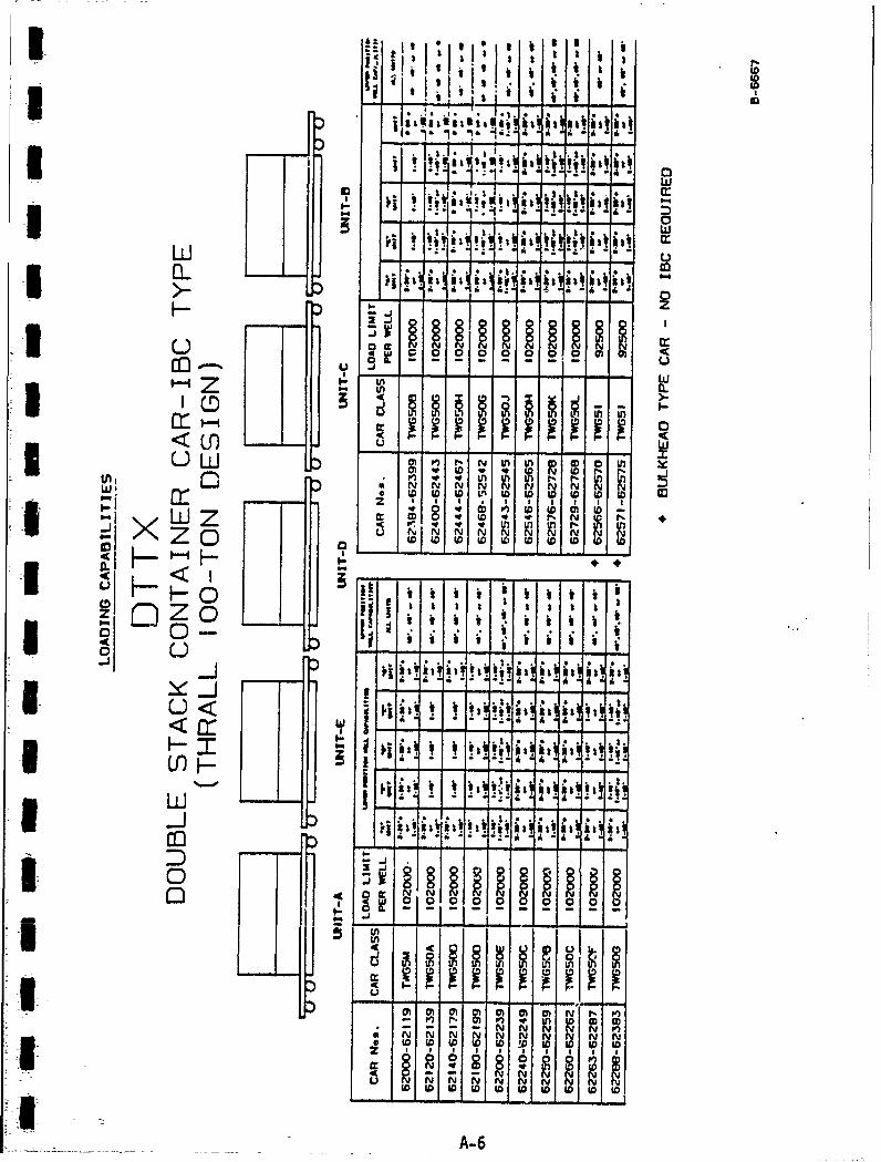
BUDD/THRALL Design "IBC" cars 11
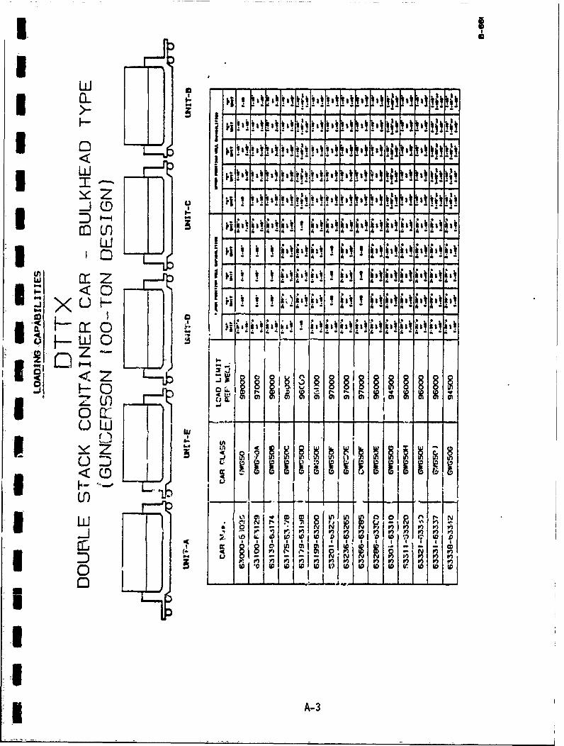
GUNDERSON Design "Bulkhead" cars 12
Containers and Trailers 13
International Containers 14
Domestic Containers 14
I Container- Handling Equipment 15
Dockside Cranes 15
Mobile Container Handling Equipment 17
:3 Chassis 18
Diesel Electric Locomotives 19
4. Switching Railcars 21
Physical Restrictions 21
LZ Loading philosophies 22
Track and Train Dynamics 23
Blocking the Train 26Ii

Outside Agencies 26
1Switching principles 27
5. Methodology and Results 35
Interviews 35
3m Simulation 36
Basic Computer Model 40
I Advanced Computer Model 48
I Model with Entrance Interdiction 49
6. Conclusiorns and Recommendations 51
Conclusions 51
Recommendations 54
Works Cited 5-7
Ao n d i. Pag
SA. Trailer Train Loading Capabilities A-I
DTTX Double Stack Container cars
-3 B. Questions for Facility Managers B-I
C. MicroCYCLONE Code for Basic (Single C-iI Track) Model
D. MicroCYCLONE Code and Logic Diagram 0-13 for Advanced (Three Track) Model
E. MicroCYCLONE Code and Logic Diagram for E-1Advanced (Single Track with EntranceInterdiction) Model
i_ l
lI
U ii
LIST OF FIGURES
Figure
1 4.1 Cars under Compression 25
4.2 Cars under Tension 25
4.3 Cars on a storage track 28
1 4.4 Locomotive and cars ready to move 31
4.5 Locomotive and cars ready to uncouple 33
1 5.1 Basic Model Logic Network 41
* LIST OF TABLES
5.1 Time Required to Perform Switching 42
1 5.2 Set Times in Model 44
5.3 Production with Various Numbers of 46
1 Trucks
5.4 Production with Various Distributions 47
5.5 Production with Various Uniform 48
Distributions
1 5.6 Comparison of Production 49
i
U
:1* i

1. 11.24 r IROC> (- C=r III
IDuring the 1980's American railroads entered into a
new technological era which some consider to be making a
far greater change than the conversion from steam to
diesel locomotives. This change occurred in the basic
3I elements of freight handling and distribution. The
deregulation of intermodal freight and the railroad
Ui; industry by the StaggersAct caused the railroads to
-i usher in new marketing strategies in order to become more
competitive with the trucking industry. For over a
I centuiry boxcars provided the standard vehicle for
transporting general goods. Just after the turn of the
3 century, some railroads began using containers and
piggyback trailers for less than car load and special
shipments. Gradually more of this intermodal transport
was being used by raiiroads, and *y the late seventies,
railroads began to reserve entire trains for intermodal
traffic. 4aiwrd:j
The smooth operation of an intermodal port is
dependent upon many factors, including the efficient
operation of the intermodal rail transfer facility. At
the present time, it is difficult to plan the development
of a new facility or to optimize the operation of an
existing one because accurate methods for predicting the
capacity and processing time are not available. A
i computer model which simulates the loading of rail cars
iI

1has beer. developed at the University of Washington
3l (Hollar 1989). However, this model does not simulate
the effects of switching the loaded rail cars. The
purpose of this project is to develop a computer model
3l which simulates rail switching in a generic intermodal
facility.
* The computer model will be developed after reviewing
the configuration of several rail intermodal facilities.
I A preliminary selection of parameters to be modeled will
be made after a literature review. Examples of
parameters to be i-ncluded are the time required to rull
3I and set rail cars in the loading area, the cycle time for
loading a container on a rail car, and the arrival
distribution of incoming and outgoing containers. Once
developed, the model will be operated and a sensitivity
analysis will be conducted to determine which parameters
3 have the greatest influence on intermodal yard capacity.
A modified version of the model should be helpful in
l answering the following questions:
(1) What is the most efficient use of existing
plant and equipment at a given intermodal facilitil?
3l (2) Would additional tracks be beneficial?
(3) Would additional loading equipment be
*l beneficial?
(4) Is it most efficient to own the rail switching
equipment, or to hire a terminal railroad to switch the
yard?
I 2
(5) Is on dock rail an advantage?
m By being able to simulate the operation of a
iUi proposed intermodal yard before large capital investments
are made, facility owners and planners will be confident
that they have made the right choice. They will be able
to design new intermodal yards and improve upon existing
ones with greater confidence. Operational improvement
can be studied without actually changing the operation.
I3
U
ImII
II
I2. LITERA TUR E SEAL C"]I
A literature search was conducted to see what, if
any, other efforts had been undertaken in this topic
3 area. Sources of information explored included data
bases, theses, railroad trade magazines, and other
3 simulation models. It was concluded that in the open
literature, no information is available concerning the
simulation modeling of intermodal rail switching.
3 Trade magazines proved to be a valuable source of
general information about intermodal facilities and
equipment. Several arti~cles have been written recently
which describe current trends in intermodal
transportation. Topics include the increasing revenue
Sshare which intermodal service provides contemporary
railroads (Welty 1989; "Intermodal" 1989) and intermodal
3l marketing strategies (Plous 1987; Greenwood 1988; Sorrow
1989; Miller 1989).
Model railroading hobby magazines also provide a
3 wealth of valuable information on this topic. While
primarily aimed at hobbyists, these magazines contain
3 large numbers of prototype scale drawings, data, and
information (Panza 1987; Casdorph 1988; Panza and
Yungkurth 1989).
3 A computer simulation is a valuable tool for
studying and :optimizing existing port operations or for
3developing plans for a new facilit-y. The result of a
3-4

1I
simulation is often in the form of graphs and tables.
I Recently, simulation software packages have been
developed Which include graphics. These packages provide
output in a form which is easily understood by people
3 with non-technical backgrounds.
Railroad operational simulations available include
three developed by the Association of American Railroads
(AAR) including a Train Operation Simulator (TOS)
S(Luttrell, et. al. 1983), an Intermodal Equipment
l Distribution Model (IEDK) developed in 1988 and an
Intermodal Terminal Design Model (TSD) developed in 1986.
3The TOS simulates the performance of diesel-electric
locomotives and freight cars over a given track. The
model will operate on an IBM PC AT or IBM PS-2. The IEDH
is intended to optimize intermodal equipment distribution
and is suitable for mainframe operation only. The TSD is
I a set of four Lotus based models intended for preliminary
design investigations of intermodal terminals. This
:3 model is not suited for detai-led terminal design or
simulation. The Trai-n Simulator (1980) is a package
similar to the TOS described above. This software will
3 run on an IBM PC and is primarily intended for training
personnel in train handling skills. The Princeton
* Railroad Network Model and Graphic Information System
(ALK Associates 1986) simulates the North American rail
73 system and provides graphic display of traffic corridor
3.i and shipping data; it is oriented toward railroad
5

2
planning, marketing, and operations. This model provides
I a PC version of the IEDM described above. None of the
above models was deemed to have direct application in
this study.
3 In addition, a review was conducted to determine the
best simulation software to use for the model. A total
3 Iof three software packages received serious
consideration. The first was SIMAN (Pedgen 1987), and
the second was SIMSCRIPT (Fayek 1989). Both of these
-- software packages include animation, both were deemed too
complicated for this study owing to the limited time
- Iavailable in which to conduct it. The software chosen
for the simulation model was MicroCYCLONE (Halpin 1990).
The MicroCYCLONE software does ,,ot have graphics
3 capabilities.
II
III
I
i133,. I TERMODAP~L EQUXPM4ENT
Previous efforts to classify intermodal railcars
have focussed on the age of a cars' design, dividing them
3 into Ist, 2nd, and 3rd generation cars (McKenzie, North
and Smith 1989). These categories refer to the cars'
3i function, including functional conversions made by the
railroads and car manufacturers to meet changing marketIdemand. Intermodal cars can.be divided into three main
3 categories, which can be further divided into ten sub-
categories. Hajor categories that can be recognized are
<3 as follows:
U i. CONVENTIONAL PIGGYBACK TRAILER (TOFC) CARS
3 * Conversions
* Contemporary Design, single unit
3 * Contemporary design, articulated
2. CONTAINER INTERMODAL (COFC) CARS
3 Conversions* Contemporary design single unit, single and
Ii double stack
* Contemporary design, articulated, single
'3! stack
'3l , Contemporary design, articulated, double
stack, IBC
I7/

Im
Contemporary design, articulated, double
I stack, bulkhead
3. DUAL PURPOSE (TOFC/COFC) CARS
3 * Conversions
* Contemporary designs
The first intermodal cars were simply 40- and 50-
1 foot flat cars. Most were not specially equipped in any
3way to carry trailers. The trailers were attached in any
way possible using chain falls, gripes or come alongs
These cars were "circus loaded" which is to say, loaded
the same way that Teamsters loaded and unloaded circus
wagons a hundred years ago. This is also the origin of
3 the term "team track" for the tracks in an intermodal
yard.
3 Circus loading and unloading is difficult and
inefficient. For one thing, the trailers to be unl-oaded-
must be oriented with the hitch end toward the unloading
ramp. A hostler had to back the tractor onto the car,
hitch up the trailer, and then pull it off by moving
3m forward. Temporary, or permanent fold down ramps, known
as "bridgeplates", were placed between the cars to permit
:5 the tractor-trailers to drive off.
3i Loading empty flat cars was even trickier; the
tractor-trailer hostler had to back the whole rig down
I i,8
II
the length of the cars being loaded. This was slow work
which required great skill on the part of the hostler.
3I Advances in hydraulics and metallurgy permitted the
development of side loading technology, which became wide
I spread about 1980. This was a critical step in
I developing the high speed doublestack trains we know
today.
3 In modern rail car design there are several
important factors which must be considered. Final total
I cost comes to mind first. Converting and refurbishing
I older cars is generallV less expensi-ve than building new
cars from the ground up. Two other important
3 considerations are the tare weight and carrying capacity;
the lighter a car can be, the better. As one might
I expect, a stronger- car is preferred over a car with less
I carrying capacity. The type and flexibil-ity of the
trailers or containers to be carried are also important.
3 Some specialized designs are needed for specific markets
and corridors, but, in general, more flexible designs are
I more satisfactory. Width and height restrictions,
stability, cushioning of the load, and length all relate
to train and track dynamics.
i3 The following information represents a summary of
the information contained in an article which discussed
3 the subject in detail (Casdorph 1988)-. For sake of
brevity, discussion in this paper will be limited to the
I contemporary design, articulated, doublestack type cars,
i1

I
3 both bulkhead and interbox connector (IBC). These two
car types make Lp the great majority of railcars
I operating in modern intermodal facilities, and therefore
are considered representational for modeling purposes.
1CONTAINER INTERMODAL (COFC) RAILCARS
3m Most intermodal railcars are owned by Trailer Train
Company of Chicago, Illinois. Trailer Train is jointly
1 owned by the major U.S. railroads and acts as a leasing
agent, providing intermodal railcars to the railroads.
CONTEMPORARY DESIGN. ARTICULATED. DOUBLE STACK CARS
This category has provided the most dramatic
i illustration of the intermodal revolution. The cars were
designed for unit train operation in heavy traffic
3 corridors, but they have also made their way into less
dense corridors and even mixed freight trains. Three
basic designs have entered service since 1979.
I ACF/SP DESIGN. "BULKHEAD" CAR-
Prototype double stacks were unveiled by Southern
Pacific in 1979 as three-unit cars. They were a
I conceptual extension of the single-unit double stack
gI designs which were introduced by American Car Foundries
(ACF) and Southern Pacific Railway (SP) in 1977. In
! 10

I
1981, following the success of the prototype cars, ACF
built 42 five-unit cars for the Southern Pacific. They
were initially used for SP Sea-Land Service trains.
3 While no longer in production, these cars led the way for
lg large scale acceptance of other five-unit designs.
BUDD/THRALL DESIGN "ISC" CARS
American President Lines (APL) placed its first
3 five-unit, 40-foot well, double stack cars in service in
1984. These cars were designed by the Budd Company of
Philadelphia, Pennsylvania and were built by the Thrall
3 Car Manufacturing Company of Chicago Heights, Illinois.
One of the major features of the "Thrall cars" was the
I3 use of interbox connectors (IBCs) to load and lock the
containers in position. An IBC is a device which is
I inserted into receptacles at each top corner of a
5 container. A second container is fastened on top of the
lower container and locked into position by rotati-ng the
3 IBC. This procedure permits easier and faster loading
than the bulkhead system introduced by ACF and SP seven
I years earlier. The cars are popular with terminal
operators for this reason. Additionally, the tare weight
of the car is less, permitting a slight increase in
capacity.
When doublestack cars were first designed, the
3 standard length of containers was 20 or 40 feet. By
1985, domestic customers had seen the advantages of
11I,!

II
containers in new, longer lengths. Eventually, 45- and
i 48-foot containers were introduced and, in 1988, 53-foot
containers appeared. Thrall introduced new cars with
well lengths to accommodate the rise in domestic
3container shipments, including the 45- and 48-foot
lengths. (See Appendix A).
!GUNDERSON DESIGN "BULKHEAD" CARS
IGunderson Inc. of Portland, Oregon introduced its
version of double stack cars later in 1984. Gunderson's
cars were similar to the earlier ACF/SP design in that
I they used bulkheads to secure the containers. The
advantage offered by Gunderson was increased security
provided by the ability to lock the containers. This was
important because, obviously, losing a container from
high winds, rough track, or other causes is costly. The
main disadvantage of the 'system is a slightly longer
loading time and lesser gross weight capacity. The first
production deliveries of these cars were made in early
1985. They were limited in the lengths, and types, of
containers they could carry, but soon Gunderson began
3 introducing cars that could hold 20-, 35-, 40-, 45- and
48-foot containers. Since 1985, Gunderson has delivered
nearly 4,COO wells. (See Appendix A).
1
7112
I,
CONTAINERS AND TRAILERSIGENERAL CARGO CONTAINERS
The International Standards Organization (ISO) first
5 lpublished a standard for containers in 1973 (Standard
668, Series 1). ISO standards describe over 20 different
types of series I containers. They can be further
divided into two broad groups: (1) general cargo
containers and (2) specific cargo containers. General
cargo containers are those not intended to carry any
particular type of goods. Specific cargo containers are
3l for shipping goods that require temperature control,
liquids and gases, dry bulk solids, or items such as
automobiles and livestock.
j For simplicity, c-nly general cargo containers need
be considered for purposes of this study. Within the
general cargo container group, the most common is the
general purpose container or "dry van." It is totally
Ienclosed and weatherproof, has a rigid roof, floor, side
walls and end walls, has doors in at least one end wall,
and is suitable for carrying the greatest possible
1 variety of cargo. Other general cargo containers include
open top containers and vented containers (passive1*l ventilation).
13Il

I
INTERNATIcNAL CONTAINERS
Containers designated Series i by ISO are those
containers intended for intercontinental use;
i consequently, these must be built to endure the rigors of
£I, shipboard service. ISO staidard containers come in
various lengths, ranging from 10 to 45 feet. Standard
i!f containers are 96 inches wide and either 9 or 9 1/2 feet
high, and there are many types. The most common
!i containers on US highways and railroads are 20 and 40
foot ISO Series I containers. In 1988, the worldwide
fleet of freight containers of all types was estimated to
3 be nearly 5 million units. Most numerous is the "dry
van," while the more exotic tank container is less
I common.
;I: DOMESTIC CONTAINERS
i3 Domestic containers are containers built exclusively
for use within the US. As such, they are not required to
ji comply with ISO Series 1 standards. Because of recent
changes in ICC regulations permitting longer and heavier
trailers on US highways, these now include 45-, 48-, and
53-foot high-cube (102-inch wide by 9 1/2 foot high) dry
vans. These general cargo containers are intended forII rail and highway service only, although 45-foot boxes
built to ISO standards may occasionally be used aboard
ship, as all .have standard ISO corner castings located at
* Ithe 40-foot positions on both the top and bottom to
14

I
permit stacking with standard 40foot containers. APC
introduced 48-foot containers in the domestic market in
1985 and followed with the first 53-foot containers in
1988 (McKenzie, North and Smith 1989).
CONTAINER HANDLING EQUIPMENT.
In the late 1950's freight containers were
introduced into both the international and domestic
container transportation networks. Almost immediately,
the need for specialized equipment to handle containers
3l became apparent. In those early days of
containerization, carriers made do with cranes, hoists
and trailers that were not originally designed for
j Icontainerized cargo. Such "band aid" and temporary fixes
did not last long, however. In today's market in which
5most of the international shipment of non-bulk
commodities is accomplished using containers, there are
numerous manufacturers of cranes, hoists, and chassis
specifically designed to lift and move containers.
jx DOCKSIDE CRANES
The first containerships had their" own cranes
onboard for ioading and unloading containers. This
occurred because most ports in the early 1960's did not
have container cranes. As containers increased in size,
weight, and numbers, this arrangement became less
15

I
satisfactory. The more progressive ports soon acquired
suitable dockside cranes specifically designed for the
new technology. Steamship lines also began to acquire
5I container handling cranes for their own dock facilities.
Today, every major seaport in the world that servesIcontainer ships has at least one or more dockside cranes
3 specifically designed for loading and unloading
containers.
* The first dockside container cranes were the hinged
boom type. Normally, the cable was attached to a
'5I rectangular lifting frame of approximately the same
3i dimensions as a container. The lifting frame had a
container hook suspended from each corner. To lift a
j' container, the four hooks were inserted into the top
corner castings on the container. The standard ISO
corner casting still has an opening on its side where a
1 hook can be inserted. This type of lifting is rarely
done anymore in the United States, but remains common in
east Africa, and perhaps other less developed areas.
Gantry cranes have now largely replaced dockside
boom cranes. A gantry crane is supported by two
I vertical trestles and is built much like a bridge. It has
a long horizontal boom which extends out over the water
U or container ships when they are pierside. The cranes
are usually rail mounted and move along the dock parallel
to the edge. A "spreader bar" has replaced the lifting
frame. The "spreader" is suspended from the crane's boom
16
I
by the hoisting cables and has "twistlocks" on each of
its four corners instead of hooks. The "twistlocks" are
inserted into the top corner castings of the container
and rotated to lock into place. Once the container is
gproperly engaged by the spreader, it can be lifted.
Modern spreaders are telescopic and can adjust to
£ different container lengths. They also have self-
leveling systems which help avoid damage to the
I container's contents during the lift.
5I Modern container gantry cranes are massive
structures. The newest ones are designed to load and
3 unload the latest generation of post--Panamax ships.
These newest cranes have a range over 150 feet, a lifting
21I height of over 100 feet and a lifting capacity of greater
than 50 tons.
MOBILE CONTAINER HANDLING EQUIPMENT
Many different types of mobile equipment for moving,
if stacking and lifting containers have been developed since
the beginning of the intermodal revolution. All of these
machines perform the function of lifting containers on or
1 off railcars, but use different designs and
configurations. They are known by a variety of names,
including stackers, packers, frontiift trucks, side
loaders, straddle carriers, and stacking gantry cranes.
E! Basically, there are two distinct categories of mobile
container handling equipment: machines that lift
17I

1I
containers or trailers from the side and machines that
I lift from the top of, or straddle, them. Within these
I two categories, there are many variations.
Machines in both categories may have spreaders
3I similar in design and function to those used or dockside
gantry cranes to lift containers from the top. They may
IH have grapple arms to lift a container from the bottom.
In some cases they may have both, the twist locks on the
spreader normally being used for containers and the
grapple arms being used for trailers. Forklift trucks
can be used to lift containers fitted with forklift
pockets. Some of the machines are more versatile and can
perform multiple tasks, including stacking containers for
storage, and loading both railcars and chassis. Others
may only perform a single function such as stacking empty
1containers,
A chassis is simply a trailer designed specifically
if for hauling containers by tractor truck. It is basically
a skeletal frame platform equipped with twistlocks to
i secure the container, a bogie assembly, landing gear, a
kingpin, and necessary electrical and pneumatic devices.
1 While most chassis are built for over-the-road use, some,
'3 known as bomb carts, *are intended strictly for use within
container yards and terminals. Highway chassis must have
I brakes, lights and licenses for use over public roads,

II
and employ a twistlock container securing system. Yard
5I chassis do not need highway safety equipment and employ
simple corner brackets to hold the container in place
I (McKenzie, North and Smith 1989).
As with other intermodal equipment, chassis come in
a variety of sizes and types, including chassis for 20-
-- foot containers only and chassis for 40-foot containers.
There are extenda" .;hassis to accommodate different
I length containers, "Gooseneck" chassis for high cube
containers and "Dropframe" chassis for tank containers.
IDIESEL-ELECTRIC LOCOMOTIVES
The last required piece of equipment is the diesel-
electric switching locomotive. The diesel engine was
invented in 1901. By the 1930's, the weight and bulk of
the diesel engine could be reduced to the point at which
it was feasible to use it as a source of motive power.
Today the American diesel-electric locomotive is in its
I third generation of development (Armstrong 1982).
;I The basic principle involved is simple. The diesel
engine is not mechanically connected to the wheels.
Instead, the engine functions as the prime mover for a
generator that produces electricity. The electricity is
'I used to operate various electrical loads in the
3i locomotive. Of prime interest are the "traction motors"
III

II
that actually power the locomotive's wheels. There are
also several auxiliary loads. One of the most important
is the air compressor which supplies compressed air for
the train's brake lines.
2
II!II
<IIII
ill ;20

4. SWITCHI-INC RAILCARES
The need for switching arises from several factors.
The physical restrictions of the intermodal facility and
rail yard are among the most obvious, and, for the most
part, these restrictions will determine the yard's
-* capacity. Switching may also be required because of
loading philosophies, train and track dynamics, the need
to block the train at origin or for the various
I destinations, and also a number of miscellaneous factors,
all of which will be discussed in more detail below.
PHYSICAL RESTRICTIONS
Physical restrictions on growth are probably the
most important constraints that managers of intermodal
I facilities and rail yards face. Intermodal yards are, by
their very nature, very likely to be located on a
congested urban waterfront where land for expansion is
either extremely expensive, or not available at any
price. There is ongoing, keen competition for this
waterfront property, and there will continue to be so.
I The various political, socioeconomic, and environmental
factors all combine to make development of new waterfront
facili -, ies, or expansion of existing ones, difficult or
impossible. An intermodal yard in the middle of Nebraska
could be huge, but since there are no ships in Nebraska,
II it would serve no purpose. These restrictions on
21I,

I
-xpansion and lack of existing space are major factors in
I determining the particular loading philosophy a yard will
employ.
IThere are two basic loading philosophies that can be
identified. Intermodal yards can be operated by the "car
assignment" method or the "load lining" method. In load
lining, all the container's that enter a yard are unloaded
and stored in a specific location by destination. Load
I lining is efficient ir terms of switching and car
I loading, but takes up a tremendous amount of space- space
that many intermodal facilities do not have.
3l In contrast to load lining, car assignment is a more
efficient use of space, but less so in terms of switching
I and car loading. In car assignment, containers are
loaded onto freight cars for shipment as they arrive in
the yard. The terminal manager attempts to load in
entire car with containers going to just one destination.
However, in a pure car assignment system, no containers
J1 are stored. If a car must be loaded with containers
i1 going to two separate destinations, it is, which means
the car must be partially unloaded at the first
21: destination before the car can proceed to the next
destination. Partial u.inloading may also result in a
specific car becoming "unqualified," (see next section)
22
I .

II
forcing it to remain at its present location until
I another load can be found for it.
TRAIN AND TRACK DYNAMICS
Because of the risk of derailments, the track and
train dynamics over the route of travel must be
considered as the train is being made up. Going uphill
on a curve, lightly loaded cars that are being pulled
I (under tension or "draft") will tend to ride up on the
inside rail, being pulled to the middle of the curve and
derailed by the effective lateral force acting on the
stretched cars. Rolling downhill and around a curve, the
cars under compression ("buff") will tend to ride up the
outside rail and be derailed by the effective lateral
force acting on the bunched cars. (See Figures 4.1 and
4.2).
* The restrictions regarding qual-ified cars provide
another reasc- why all wells on the same car cannot
always be loa-,: 'or the same destination. In order for
the car to be fully loaded, it would have to be delayed
until enough boxes for that destination arrive, or sent
out with empty wells. To wait is undesirable because, in
intermodal, speed is of the essence, and to send a car
3 out with empty wells violates the rules at best and can
cause a derailment at worst. This is why, at a typical
intermodal yard, switch engines are kept busy while
3l managers consider all these various problems. Adding to
23

II
the puzzle is the fact that some customers want their
1 cargo shipped and delivered in containers, while others
demand trailers. While the actual loading is done by the
Ushipping company at origip, it remains the intermodal
terminal manager's problem'to find the correct type of
car tc load the container or trailer aboard.
ll Burlington Northern Railroad (BN), for example, has
mountain restrictions east of Seattle, which were
developed to minimize derailments. ihe restrictions over
this line affect (1) the total tonnage of the train, (2)
the length and total number of cars that can be in the
3 train, and (3) whether or not cars can be run empty or
must be loaded.
: BN's major traffic corridor between Seattle and
Chicago must cross the Cascade Mountain range. This line
has a maximum grade of 2.2% and many tight curves.
3 Specific restrictions imposed are that the first 25 cars
of all trains must be "qualified"; that is, conventional
cars must bL loaded with two trailers or containers on
each car, and a doublestack car must have at least one
-lI container in each well. A train of less than 5500 tons
3 can be pulled with locomotives on the head end only, and
trains which exceed this limit, but are less than 7500
i tons and under 7700 feet long (about 25 contemporary
design, articulated intermodal cars), must have helper
locomotives cut into the middle of the train. An all-
conventional intermodal car train may total no more than
24I

i
Iderailed cars
1 %
I tI effective lateral~force
compressi e compressiveforce forceI
II
Figure 4.1: Cars going downhill on a curve, under
compression
derailed cars
I effective lateralforce
3 tensile tensileforce force
IFigure 4.2: Cars going uphill on a curve, under tension
25

45 cars (about 4050 feet). In a mixed conventional and
doublestack train, the total weight must be less than
4800 tons, all doublestacks must be at the head end, and
all conventional cars at the rear. A solid doublestack
train cannot run empty wells anywhere in the train. Most
other railroads, especially in the west, face
i :restrictions similar to those of Burlington Northern.
BLOCKING THE TRAIN
Inevitably, trains must be switched at both origin
and destination. However, trains are always blocked at
3l their origin by destination. In other words, they must
be arranged so that all the cars going to the same
3! destination are placed together in the train. This makes
it easier for the train crew to set out and pick up cars
I enroute. It is common practice for the cars to be set
3 out first to be placed at the beginning of the train, but
it should be noted that, as previously stated, rules
governing placement of "qualified" cars take precedence
above blocking by destination. As an example, there are
commonly five to seven blocks for each train departing
3 Seattle on the Burlington Northern.
OUrTSIDE AGENIES
Other agencies influence intermodal operations,
often making it difficult or impossible to predict
5! accurately how many and what type of containers or
26Il

I
3: trailers will arrive on any given day. These agencies
include but are not limited to US Customs, which may have
I to delay a particular container or a whole shipment until
3I it can be properly inspected. The labor agreements that
have been negotiated with the Long Shoremen and Teamsters
3I Unions often include shut down time for breaks and
restrictions on the hours of work.
In intermodal yards, cars are generally set with
double stack cars on one track and conventional
intermodal cars on another track. On any given day, it
3 is impossible to predict the number of containers that
will go to a particular- destination. Therefore, it is
SiI impossible to preassign cars by destination within a yard
3 Iand to always load a car with containers or trailers
going to the same destination. Thus, the requirement for
3 switching is inevitable.
3 SWITCHING PRINCIPLESa
3 Switching is considered to be a necessary evil in
operating a railroad. The switching crew normally
3 includes an engineer, who operates the locomotive; one or
more brakemen, who handle the chores on the ground such
as coupling and uncoupling the cars and throwing
switches; and a switch foreman. The brakemen are often
SUIi required to climb on and jump off slowly moving rolling
Sstock, as they ride on the cars in order to travel
between locations of successive tasks.
* 27

I0I-
ILIL
castbemoe
loootv
LiJL
Figure4 .3: ars ona storge tr c nar i to rd
3 be move

I
UFor sake of illustration, consider a cut of cars
3 sitting on a storage track in a yard. This cut must be
moved to a team track in an intermodal yard and then
I loaded with containers. This situation is illustrated in
Figure 4.3. The first person in the process is the
terminal manager, who is in charge of the terminal and
3l knows the day's scheduled ship and train arrivals and
departures. The terminal manager informs the train
3l master that an empty car is needed for loading. The
Trainmaster is the person in overall charge of the yard
tracks and is in radio contact with the individual
3l locomotives through other personnel in the yard tower or
office. Next, a switching crew is called on the radio
3 and is given the location and equipment identification
number of the car to be moved. While the locomotive is
I being operated to the car's location by the engineer, the
3 brakeman is not needed on the ground and usually rides in
the locomotive cab, perhaps helping the engineer observe
3l any conflicting traffic or other problems. When the
locomotive reaches the car in question, the engineer
Ii approaches it slowly and the brakeman swings off the
l locomotive and walks to the car. Using hand signals or,
preferably, hand held two-way radios, the brakeman guidesm
the engineer as the locomotive moves closer, to the car,
stopping when the knuckles of the couplers engage and
I lock. Now the brakeman must go between the locomotive
and car and connect the air hoses or "glad hands", which
29

IU
are part of the braking system (as explained in the next
3I paragraph). There are valves known as angle cocks on all
the air hoses; the brakeman confirms that the angle cocks
on the two hoses he just connected are both open and that
3 the valve on the other end of the car is closed.
Miodern freight cars are equipped with two kinds of
brakes: air brakes for primary use while in a train, and
hand brakes which are used in spotting a car by itself on
a siding when train air, is not available. When switching
3 light loads, such as a single box car, often the train
air lines are not connected; consequently, the air brakes
3 are not used. However, the five well articulated type
cars which are used in container loading are considered
I3 too heavy for a small switch engine to move safel
without the use of air brakes. The air brakes are held
U off by air pressure; this is a safety design so that if
3I air pressure is lost at any time, say because a coupler
brakes and the train is parted, then the loss of the air
>3- pressure will cause the brakes to be applied. The air
hose is connected from the switch engine to the car, and
the air compressor in the switch engine pumps to bring
.3 the air pressure up to an acceptable level in the train's
braking system. If the air hose valve at the other end
of the car is open by mistake, then the train line will
not hold air pressure and the brakeman will have to walk
U to the other end of the car to close the valve. Since
'I many modern articulated cars can be over 300 feet long,
30

CIIbIU
LLJ)
CC4
wU
Fiur -4 oooi eadcr eayt oe
U3

U
the walk can be quite time consuming. With both valves
3 closed, the air pressure is increased, and the brakes on
the car are released. The locomotive and car are now
ready to move. This situation is illustrated in Figure
1 4.4.
The braieman way climb aboard either the locomotive
Sor the car for the ride to the team track. Depending on
the distance, thiF may take several minutes. The speed
I for trains within yard limits is typically restricted.
From the author's observations, five mph is a typical
speed for operation in an intermod3l yard.
3l Once the locomotive and cut of cars arrives at the
team track, the engi7vrr slows the train, again
permitting the brakeman to swing to the ground. The
brakeman will probably have to throw one or more switches
in order to align the tracks so that the car can be
3I- placed or spotted on the correct track. This done, he
signals the engineer to proceed via radio or hand signal.
The car is slowly pushed intc the correct position. This
situation is illustrated in Figure 4.5. The locomotive
must now be uncoupled from the cars. The brakeman may go
between the cars and close both air valves: one on the
car, the other on the locomotive air hose. if this is
done, the brakes are not applied and the car is free to
roll after the locomotive leaves. Alternatively, if one
i of the valves is left open, the air will escape from the
3 fair lines on the car and the brakes will Putomatically
I '2

I~
UU
I-- L-
Fiur 4.5 L comtv n asrad o nopig
K I-I 33

I
set. After both air valves are closed, the brakeman
I steps back out alongside the track and pulls a lever
which allows the coupler to open. Now the brakeman
signals the engineer, who backs the locomotive away. The
air hoses separate without assistance. The hand brake
wheel is then turned to actuate a secondary mec-anical
3I braking system that serves the same function as a parking
brake for an automobile.
i
I
:I
Ii
1 34

15. MMIXCX>>Mc C " A~kTW XMSLTLX'IS
The investigation into operation of intermodal
facilities consisted of a series of on site interviews
followed by the development of a computer simulation.
U This chapter describes the methods and techniques used in
developing the study. A discussion of the site visits is
presented first, followed by a general discussion of
simulation modeling. A detailed discussion of
MicroCYCLONE modeling methods is the final part of this
chapter.
I I t~NT ER VT EVS
j) Familiarity with intermodal switching is required
before one can develop a meaningful computer model. To
3 facilitate this, a group of standard questions was
developed in order to ensure that all major points were
Il discussed. The interviews also served the purpose of
3 ~ ensuring that the author would become familiar with the
terminology and concepts associated with intermodal
1 terminal operations. The questions and a brief summary
of results are contained in Appendix B.
,! The criteria for choosing sites to visit were two
Ifold. First, it would be desirable to visit sites in asmany different geographic regions of the United States as
1 possible. Second, it would be desirable to visit
terminal-s operated by as many different railroads as
35

i
possible. It was hoped these criteria would insure that
information gathered would not contain proprietary or
geographical limitations.
The fol lowing sites were visited:
Burlington Northern Seattle International
Gateway, Seattle, Washington.
Burlington Northern Balmer Yard, Seattle,
I ashi rgton.
Southern Pacific Intermod31 Terminal,
Oakland, California.IAtchison, Topeka and Santa Fe Richmond Yard,
Ii Richmond, California.
IBurlington Northern Chicago International
Gateway, Cicero, Illinois.
I ~SIMUIL A TION
A simulation is a mathematical model of some
historical event or activity which attempts to reproduce
the most important aspects of the event or activity being
in question, often in order to study and make predictions
I- about future events. A previous study of intermodal
operations (Hollar 1989) has suggested dividing these
IC 36

II
aspects into two categories, physical constraints and
operational constraints. Physical constraints on a model
of rail switching in an intermodal facility would include
the physical size of the rail cars, the speed at which
they are moved, the number of tracks in the facility, and
I the time required for personnel to carry out tasks like
throwing a switch or coupling and uncoupling cars.
Operational constraints include items like labor
agreements and industry rules and regulations.
Simulation models rely heavily on the laws of
I mathematical probability to simulate real life
occurrences. Once a model is developed, comparison of
results to existing hi3torical data must be made. In
game theory this is referred to as play testing, and i-n
simulation models it might best be described as
I authenticating or verifying the results. Following an
initial verification, the model is fine tuned. After
some number of iterations of comparison with historical
data and fine tuning, the model is considered capable of
reasonable predictions.
When making a model with the MicroCYCLONE software
(Halpin 1989), one breaks the intermodal terminal
operation is broken down into component activities,
operations, processes, and work tasks.
Work tasks are fundamental field actions, and
I generally involve only a single person or crew. Work
tasks in an intermodal yard would include a brakeman
37
*|1
couFling and uncoupling cars and throwing switches. The
engineer" oPerating the locomotive's air compressor to
pressurize the train's air line is another example of a
I work task. A worker operating a hoist and lifting a
container from a chassis to a car well is still another
example.
1l A process is a logical collection of work tasks.
Proesses usually involve more than just a single trade.
I= In an intermodal facility, the movement of a cut of cars
(loaded or empty) would represent a process.
An operation is a logical collection of processes.
An operation in an intermodal facility would be the
movement of several cuts of cars through the yard. The
operation would result in the making up of a train of
intermodal cars ready to depart the facility.
An activity is the attainment of a physical segment
of some whole. In the intermodal facility, departure of
a train would signify the completion of a full cycle.
The final model must be logical sequence of work
tasks collected into processes, further collected into
I operations. The completion of each cycle or activity
It We Indicated by a single numerical increase in the
program counter. (See function node, described below).
In order to make models with the MicroCYCLONE
program, a network is constructed with a string of logic
Ielements called nodes. There are four basic elements in
38

Uthe MicroCYCLONE language: normal, queue, combination and
function. (See legend on Figure 5.1).
A normal node is the simplest. It allows the
I modeler to specify a time duration for an event. In
contrast to the combination node (described below) the
normal node does not require that the elements preceding
3 :it be specified.
A queue node is an element which represents a place
in the network where resources are detained, or "queue"
up. A special function can be added to a queue node,
called a generate function. The generate function is
used when resources arrive in packages. For instance,
when one articulated intertodal car arrives at a
facility, it consists of ten places for containers.
The combination node must be preceded by queue
nodes. The combination node requires that resources be
available in zach of the queues preceding it before the
process can proceed through it.
There are two types of function nodes available in
MicroCYCLONE. The first is the counter node, which is
I inserted into a network in order to measure production
output. The second is the consolidate function, which is
the opposite of the generate function described above.
The consolidate function can be employed when a modeler
wants to collect resources, for example, when ten
containers are collected on one modern articulated
intermodal car.
39

I!II
BASIC COMPUTER MODEL (SINGLE TRACK FACILTTY)
Owing to the complex nature of an intermodal
operation, the approach was to develop the model as a
series of modules. Each module would represent an
increase in complexity over the previous. Experience
3i with other modeling attempts (Hollar 1989) supports this
approach.
iI The initial computer model was developed after
reviewing the configuration of the rail intermodal
facilities visited during the on-site interviews, and it
is intended to represent a generic intermodal facility.
Parameters required for a basic model include the time
required to pull and set cuts of cars on a track as
described in chapter 4, the cycle time for loading a
container on a rail car, and the arrival distribution of
incoming containers. A logic diagram of the model is
shown in Figure 5.1, and the MicroCYCLONE code is shown
1 in Appendix C.
The time required to accomplish the process of
pulling and setting a cut of cars on a track is actually
the sum of the time required to perform several
individual work tasks. The work tasks include coupling,
3pumping air, and pulling the loaded cut of cars out of
the tracks, throwing a turnout and pushing them into a
iI storage track. The engine then uncouples and moves to a
string of empty cars in the storage yard. These cars are
i.n

IU in-j
C, Li!Dto~~ W -
a- C.
IjIjC L VDi
I0
* 41

II
pulled out of the storage yard and pushed into the team
I track. The locomotive then uncouples and leaves, thereby
becoming available to repeat the cycle. Estimated time
required to perform each Work task is shown in Table 5.1.
TABLE 5.1: TIME REQUIRED TO PERFORM SWITCHING
WORK TASK TIME (min)
3 Pull cars 4000ft @ 5mph, perform twice 9
Push cars 4000ft @ 5mph, perform twice 9
I Throw turnout, perform twice 1
Couple, twice I
Pump air, twice 3
Uncouple, twice 1__
Total 24
I The Basic computer model is composed of two
processes which are joined by one work task through a
combination node. The first process delivers containers
3l from the dock and consists of nodes 1, 2, 3, 4, 5, 7 and
8 in Figure 5.1. The second process switches empty and
loaded railcars from the intermodal facility to the
3 storage tracks. It consists of nodes 5, 6, 9, 10, 11,
12, 13, 14, 15 and 16 in Figure 5.1. The program code
5 for the model is contained in Appendix C.
A 42

Node 2 represents a dock crane loading a container
onto a truck for transport to the rail facility. It is a
combination node because it requires resources to be
available before it can be accomplished, namely, a crane
at node 1 and an empty truck at node 8. The time
required to load the truck is represented by the values
in SET 1. These values specify a minimum and maximum
value between which times are assumed to be uniformly
distributed. Table 5.2 illustrates all the SET values
used in the model.
The loaded truck then proceeds to the rail facility
through node 3, with travel time as specified in SET 2.
The truck arrives and waits at the gate represented at
3 node 4. Node 5 is a combination node which requires a
loaded truck at node 4, an empty rail car at node 13 and
an idle hoist at node 9. At node 5 the container is
shifted from the truck to the rail car, requiring time
specified in SET 3. The empty truck then proceeds
5 through nodes 7 and 8 back to the dock for reloading,
with travel time stated in SET 4.
3I Node 6 is a consolidate 10 function. This function
requires 10 containers be loaded onto a rail car, fully
Il loading one articulated double stack car. This done, a
3l locomotive is called at node 10. The time required to
call the locomotive is specified in SET 5 (see Table 5.2)
and is contingent upon a loaded rail car being available
I__ _43
I
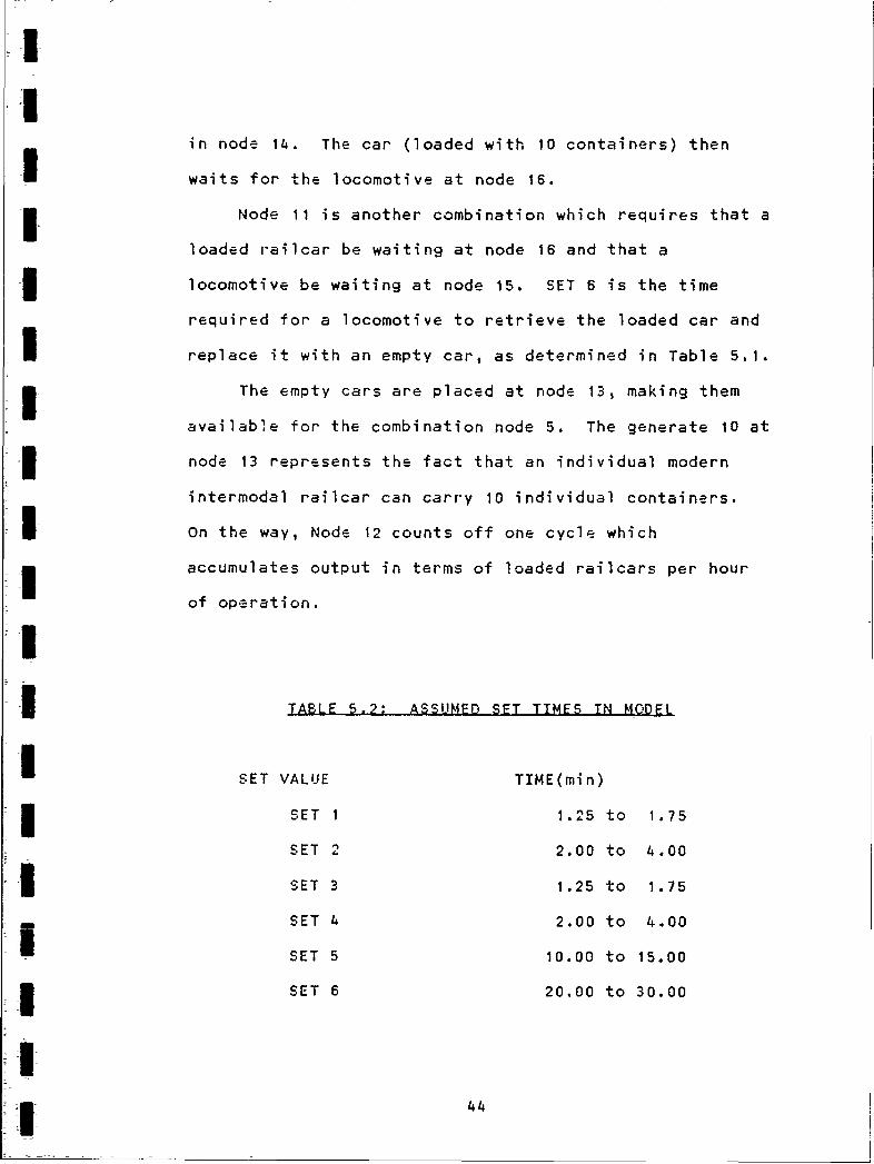
in node 14. The car (loaded with 10 containers) then
I waits for the locomotive at node 16.
Node 11 is another combination which requires that a
loaded railcar be waiting at node 16 and that a
locomotive be waiting at node 15. SET 6 is the time
required for a locomotive to retrieve the loaded car and
I replace it with an empty car, as determined in Table 5.1.
I The empty cars are placed at node 13, making them
available for the combination node 5. The generate 10 at
3 node 13 represents the fact that an individual modern
intermodal railcar can carry 10 individual containers.
On the way, Node 12 counts off one cycle which
accumulates output in terms of loaded railcars per hour
of operation.
I
3 TABLE 5.2: ASSUMED SET TIMES TN MODEL
SET VALUE TIME(min)
SET 1 1.25 to 1.75
SET 2 2.00 to 4.00
SET 3 1.25 to 1.75
SET 4 2.00 to 4.00
SET 5 10.00 to 15.00
3 SET 6 20.00 to 30.00
I
1 44

II
Ii The truck travel times have deliberately been set so
3 that they are unrealistically short, since the model is
intended to study the rail movement and not the movement
of the trucks. Keeping the truck travel time to a
minimum facilitates the examination of a larger number of
:rail movement cycles.
31 Lines 19 through 27 of the model (see Appendix 3)
represent the resource input. It was assumed that two
3cranes would be working at pier side, that two hoists
would be working in the intermodal facility, and that two
locomotives and 6 cars (30 wells) would be available.
3 The number of cars in a string could be modified by
increasing the "generate",number by any multiple of ten,
that is, 20 wells would represent two cars, 50 wells five
cars, and so on.
3 Another significant item in the model is the total
number of trucks in the cycle. Lines 21 and 22 of
Appendix C show that a total of 20 trucks are assumed to
be working. A study was conducted to determine how
sensitive the model is to the number of trucks present.
3l The basic model shown in Figure 5.1 resulted in
ANN production of 4.6 units/hour, which physically represents
1 4.6 loaded railcars in 1 hour'. This value was taken as a
benchmark and further comparisons were made against it.
It was assumed that there should be enough trucks in the
3 cycle so that the container hoists are not waiting in the
intermodal facility for trucks to arrive; that is, it is
45

i
desirable. to have the trucks waiting for the loader. The
3 niodel was run with 21 20, and 200 trucks to determine if
the level of production was affected. Results are shown
i in Table 5.3.
TABLE 5.3: PRODUCTION O'TPUT WITH VARIOUS NUMBERS OF
T RU CK SINUHMEER OF TRUCKS PRODUCTION % DIFFERENCE
2 trucks ( 1 at 4, 1 at 8) 3.0 units/hr 35
I 20 trucks ( 10 at 4, 10 at 8) 4.6 units/hr 0
200 truckz (100 at 4, 100 at 8) 4.6 units/hr 0i
It is apparent from Table 5.3 that 20 trucks are
sufficient to prevent the hoists from having to wait for
containers to arrive.
The next test performed on the model was intended to
determine how its sensitivity to the type of probability
distribution defined in lines 28 through 34 of Appendix
C. The many types of probability distributions are
covered extensively by numerous authors and are outside
i the scope of this paper. MicroCYCLONE permits the
programer to choose between the five different
.1 distributiorz shown in Table 5.4. As previously stated,
the parameters defined in Table 5.2 resulted in an output
46

I
of 4.6 units/hour, which was taken as a bench mark. The
specific type of distribution was varied as shown in
table 5.4 and results noted.
ITABLE 5.4: PRODUCTION OUTPUT WITH VARIOUS DISTRISUTIONSI
I DISTRIBUTION PRODUCTION % DIFFERENCE
Uniform (as shown in App. C) 4.6 units/hr 0.0
j Deterministic 3.4 units/hr 26.0
Triangular 1 4.6 units/hr 0.0
I Triangular 2 K 4.3 units/hr 6.5
Triangular 3 A 4.9 units/hr 6.5
Beta 4.1 units/hr 1o.e
Normal 4.1 units/hr 10.8
IFrom the results shown in Table 5.4,it was concluded
that the uniform distribution as defined was a reasonable
3approximation of rea)ity. To further refine the model,
future researchers should consider collection of actual
l data in the field to physically verify the distribution.
m The final test performed on the model was to
determine how sensitive it was to variations in the
uniform distribution. The uniformly distributed
parameters were modified as shown in Table 5.5. During
3each test the parameters not modified were returned toI 47

TI!I
t hthose shown in Table 5.2. As before-, the results were
3 compared agair,st the value of 4.6 units/hour output.
ITABLE 5.5: PRODUCTION OUTPUT WITH VARIOUS UNIFOPM
1 01DST FTS811TQ N SIUNIFORM RANGE (changed to) PPODUCTION % DIFFERENCE
3 Loco move cars 40.00 to 60.00 2.0 units/hr 56.5
Call loco 20.00 to 30.00 4.6 units/hr 0.0
Truck travel 4.00 to 8.00 4.6 units/hr 0.0
3 Hoist time 2.50 to 3.50 4.5 units/hr 2.2
IFrom Table 5.5 it is apparent that the most critical
I parameter in the model is that of the time consumed by
the locomotive in moving the cars.
3 ADVANCED COMPUITER MODEL (3 TRACK FACILITY)
A network logic diagram of a more advanced computer
model is presented with pro-pram code in Appendix 0. This
i model is a generic representation of a three track
intermodal facility, and was developed on the principle
of producing ever-increasing degrees of complication in
the model logic. Close examination will reveal that it
Ui is in reality the network logic o+ the single track
48
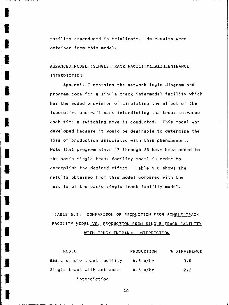
facility reproduced in triplicate. No results were
obtained from this model.
ADVANCED MODEL (SINGLE TRACK FACILITY) WITH ENTRANCE
INTERDICTION
Appendix E contains the network logic diagram and
I mprogram code for a single track intermodal facility whichi has the added provision of simulating the effect of the
locomotive and rail cars interdicting the truck entrarce
each time a switching move is conducted. This model was
developed because it would be desirable to determine the
II loss of production associated with this phenomenon..
Note that program steps 17 through 26 have been added to
the basic single track facility model in order to
accomplish the desired effect. Table 5.6 shows the
results obtained from this model compared with the
3 ~ results of the basic single track facility model.
ITABLE BS.,~ COMPARISO.N OF PRODLUCTION FROM SINGLE TRACKZ
FACILIY MODEL VS. PRODUCTION FROM SINGLE-.TRACK FACILITY
I WITH TRUCK ENTRANCE INTERDICTION
MODEL PRODUCTION % DIFFERENCE
I Basic single track facility 4.6 u/hr 0.0
Single track with entrance 4.5 u/hr 2.2
interdiction
149

II
IThere are several problems evident in this model.
Because node 26 is a combination, it must be preceded by
queue nodes. (See Chapter 5). Consequently, nodes 4,
I18, 20, 22 and 24 must be queues. Since there must be a
resource in each queue before the "crossing idle" node 26
is active, this model in effect states that there must be
four locomotives in the crossing in order for it to be
idle. This, obviously, is nonsense. A suggestion for
I further study would be to change nodes 4, 18, 20, 22 and
24 to combination nodes and node 26 to a queue. Such a
model may produce reasonable results.
IIIII
~1
IL 50

1I
6. CSNCLUSIONS ANI RH.C OMM1 - NDAT.IO N~iS
It was an objective of this study to produce a
computer model of rail switching in a hypothetical
I intermodal facility. Such a model would enable facility
designers and planners to study the effects of various
modifications before committing large capital
investments. The model developed is generic and does not
represent any specific facility. However, it is possible
to modify thE model to represent a specific facility.
Several conclusions can be drawn from this effort:
The model produces results that are not sensiti.'e to
a specific distribution.IThe modEl will be useful in determining what data
I needs to be collected. Data such as the time needed
to couple, uncouple, pump air and throw turnouts may
be found to be non-site specific. Data such as
truc' travel time to and from the dock, and time
required for the locomotive to push and pull cars
will be site specific owing to variations in the
distances involved.
I1 51

I
The model will be useful to facility managers who
wish to play "what if" games.IDeveloping computer models is difficult and time
consuming. It took much longer to develop the model
than was anticipated, probably because. learning new
software is very frustrating and time consuming.
iIThe intermodal industry is very dynamic, and
intermodal facility managers are extremely
busy people.
In addition, several problems were identified that
seem to be common to almost every intermodal facility:IThe facilities' truck entrance is interdicted by the
Itrains while they are switching cars.
Trains do not always arrive at the facility as
scheduled. This is a constant source of problems
for the facility managers, yet one which they are
SI helpless to correct.
3 Sometimes intermodal trains include non-intermodal
freight cars. This makes extra switching necessary
at the destination.
I* 52

II
I Facility managers are frustrated by the many large
number of different types and sizes of intermodal
cars and containers in service today.ISeveral problems were encountered in using
I MicroCYCLONE:
I ,.The software is very platform specific; the author
could only run it on an IBM PC/AT. This can be a
serious inconvenience.
i The author encountered several bugs in the program.
The program often cra.shes and returns the user to
the DOS without warning or explanation. This is a
source of frustration.IThere is no documentation regarding the error
messages. A common error message is "THERE IS AN
UNIDENTIFIED PROBLEM" followed by a crash back to
the DOS. A student will find this extremely
Sfrustrating.
There is no large network of MicroCYCLONE users at
the University of Washington, which makes it very
difficult to find help for even simple questions.
The authors of the software provided help by phone,
V53

II
which was greatly appreciated, but there is no
substitute for face to face assistance.
IRECOMMENDATIONS
Having completed this study, I wish to make the
following recommendations:IA dedicated data collection effort should be
Ii undertaken to gather more accurate information on
the most sensitive parameters represented in the
models. Once the accuracy of the parameters is
improved, further simulation runs should be
conducted to provide more accurate information
concerning the capacity and throughput times of a
typical intermodal facility. Gathering data for the
site specific parameters will permit study of a
3 specific facility
SI In cases where the results are distribution
m sensitive, the actual type of distribution should be
I verified by collecting a large amount of data in the
3 field.
!I5~54

II
1I The intermodal industry should make an effort to
standardize the types of railcars and the size and
types of containers in service.IStudies of intermodal facilities shoul.d include, but
not be limited to, models of this type. Planners
3 and designers should also consider other site
specific aspects such as weather, topography,
geology and othe- pertinent factors.
I One of the greatest difficulties encountered in this
research was developing the model itself. One advantage
of the MicroCYCLONE software was that it appears to be
less complex. Because it does not include a graphics
package, the student is encouraged to concentrate on the
modeling aspects of the program. Despite this apparent
simplicity, it took much longer to develop the initial
model than originally estimated. Future researchers
3 should consider the following recommendations when
choosing software for further work on this subject:
i Because of the difficulties explained above, success
with MicroCYCLONE is proportional to previous
3 experience with personal computers. It is not a
good choice unless the researcher is very proficient
in the use of computers, or has a strong local
support network.
55

UII
MicroCYCLONE users should network and exchange
information. The MicroCYCLONE newsletter, which is
published by Purdue University, might be a good
starting point.
I The authors of the MicroCYCLONE software should
publish documentation which explains the error
messages which are generated by the program.
I As a final word, I would like to say that I believe
the intermodal industry will continue to grow in the
1990's, perhaps even faster than it did in the 1980's.
Funds for public works projects are becoming more and
more difficult to obtain, and the infrastructure of the
I United States is deteriorating. Eventually, the nation's
highways may no longer be available to trucking companies
for cross country hauls. This will force a realignment
I of our national transportation economy and push rail
intermodal services to the forefront of the
* transportation industry.
III

II
I c> n IS ur 3E3,
Armstrong, John H. The Railroad- What it is. What itDoes. Omaha: Simmons-Boardman Publishing Corporation,1988.
I Casdorph, David G. "Intermodal cars of the Eighties."ilroad Model Craftsman, Nov 1988, pp 82-89.
Fayek, Abdel-Moaty M. Introduction to Combined Discret_-Continuous Similation Usina SIMSCRIPT 11.5. CACIProducts Company, La Jolla, CA., 1989.
Greenwood, William E. "E.N Moves Marketing to Forefront."Progressive Railroading, Oct 1988, pp 25-27.
IHalpin, Daniel W. MicroCYCLONE User's Manual. PurdueUniversity, 1989.
Halpin, Daniel W. MicroCYCLONE System Manual. PurdueI University, 1989.
Halpin, Daniel W. MicroCYCLONE (software). PurdueIUniversity, 1989.Hollar, Donna A. Simulation of Intermodal RailvardOperations. University of Washington Masters Thesis,1989.
Intermodal Equipment Distribution Model. Technical User'sManual. AAR TSD-88-2, May 1988.
"Intermodal: Gains on all Fronts." Progr'essive
Railroading, June 1989, pp 27-32.
Intermodal Terminal Design Models. Screening Models forAnalizing Intermodal Terminal Design and Performance, AARReport No. R-648, Jul 1986.
Luttrell, et. al. Train Operations Simulator User'sManual, AAR Report No. R-564, 1983.
McKenziej David R,; Mark C. North; Daniel S. Smith;Intermodal Transportation- The Whole Story. Omaha:Simmons-Boardman Publishing Corporation, 1988.
Miller, Luther S. "Conrail Intermodal: Improving aWinning Game." Railway Age, Jun 1989, pp 34-36.
Panza, Jim. "Modeling a VTTX car." Railroad Model
Craftsman, Sep 1987, pp 69-75
I
UU
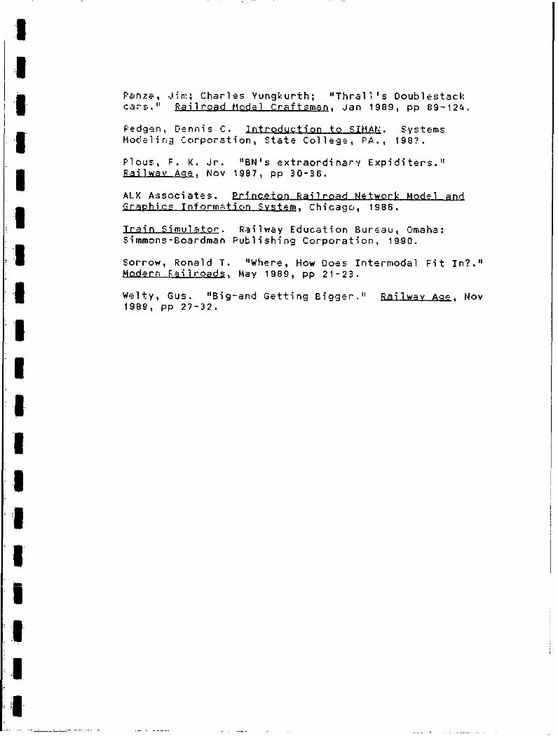
Panza, Jim; Charles Yungkurth; "Thrall's DoublestackIcars." Railroad Hodel Craftsman, Jan 1989, pp 89-124.
Pedgen, Dennis C. Introduction to SIMAN. Systems3 Modeling Corporation, State College, PA., 1987.
Plous, F. K. Jr. "BN's extraordinary Expiditers."3RilwayAge., Nov 1987, pp 30-36.
ALK Associates. Princeton Railroad Network Model andGraphics Informxtion System, Chicago, 1986.
Train Simulator. Railway Education Bureau, Omaha:Simmons-Boardman Publishing Corporation, 1990.
I Sorrow, Ronald T. "Where, How Does Intermodal Fit In?."Modern Failroads, May 1989, pp 21-23.
Welty, Gus. "Big-and Getting Bigger." RaiyL A-_ , Nov1989, pp 27-32.I
II
III
I
I
I

.... . ... . . ... ... . .i ... ... .
LOADING
CAPABILITIES
DTTXDOUBLE STACK
CONTA I NER CARS4
TRAILER TRAIN COMPANYEquipment Department
MAY I, 1989
A-1

II:I
TRAILER TRAIN COMPANY CURRENTLY HAS APPROXIMATELYI 1950 DTTX CARS (9750 WELLS) IN SERVICE OR
SCHEDULED TO BE BUILT.
THE LOADING POSSIBILITIES FOR THESE CARS DIFFERI WIDELY FROM CAR CLASS TO CAR CLASS AND FROM
BUILDER TO BUILDER.
, IN ORDER TO PROVIDE A READY REFERENCE, WE HAVEPREPARED THE FOLLOWING LOADING CAPABILITIES CHART-3WITH SUCH DATA AS BUILT DATE, WELL CAPACITY,LIGHT WEIGHT AND LOADING CAPABILITIES FOR EACHCAR CLASS AND EACH CAR SERIES.
I THESE CHARTS ARE ARRANGED ALPHABETICALLY BYCAR BUILDER AND NUMERICALLY BY CAR NUMBER.IPERIODIC UPDATING WILL BE DONE TO INCLUDE
I ADDITIONAL CARS ADDED TO THE TRAILER TRAIN FLEET.
II
II z-
LIJ tit ti
7- ...1' ' - - -
J. .11 SI ! I ! tI
J CD s.
gico U) r 4A- a-i
M I_ .UjJ - , - A M -
<0
uii 0
zD. 4 *~0 BD DO I 'I
Z j< '-4 _- W
0UQ*n A-0

1.1C* q
uJ~ - 4
< IL LU-I - - - - -
wI za~w5.~i
I~~~g I - - - .- - II e i
-)
I) Z. zufI
~ . -J
II
0 N
7111mr- r- t'- +
* A-4

I
I iI w i
# U *1
NN
* lCD
~ . -.. .
00
, *D
<u rlE ,v . ?
7 N N
,z I. ., I,. ,.,. ,
ccLI N N NN N
~ 01
-A-
I i NNN
-il 'C
o U U
(20)
It
?+-i~~~~i. ilk..,:
t I*l"1"t"I " " 'U I "I |I 1 iaI'
rI---
i- -
~-ju - -hf) f
i im 1q1 1",1 i1a r; N W N.' I- . * , u ..
', t' ' - ' " 1 '"" - "- -"1"I"
3 'CDit'l'lk! Skik s
<, ) - ' ......
z 0ww10 1 lb lb 0 lb w -
+ ++
<I
0 c
-0 1 A A I
U - < ti< c - - A In
-- -i ii.--
al k k iL& Iil s i
DI0t
CA-6

IIo- S
I>ifIL
OL. UT) * ti t ,
I" i- 400I ic.u- LD M k.d4
wUN8
uJ 4
o 00
0 dc
L.A.-iIz qI V 3
HC t D, - g
IctD 00 0 4.
00 toZ
A-7
U
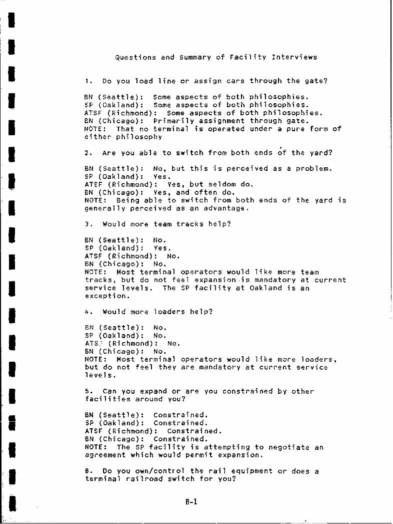
Questions and Summary of Facility Interviews
1 1. Do you load line or assign cars through the gate?
BN (Seattle): Some aspects of both philosophies.SP (Oakland): Some aspects of both philosophies.ATSF (Richmond): Some aspects of both philosophies.
EN (Chicago): Primarily assignment through gate.NOTE: That no terminal is operated under a pure form ofeither philosophy
2. Are you able to switch from both ends of the yard?
BN (Seattle): No, but this is perceived as a problem.SP (Oakland): Yes.ATSF (Richmond): Yes, but seldom do.BN (Chicago): Yes, and often do.NOTE: Being able to switch from both ends of the yard isgenerally perceived as an advantage,
3. Would more team tracks help?
I BN (Seattle): No.SP (Oakland): Yes.ATSF (Richmond): No.BN (Chicago): No.NOTE: Most terminal operators would like more teamtracks, but do not feel expansion.is mandatory at currentservice levels. The SP facility at Oakland is anexception.
* 4. Would more loaders help?
BN (Seattle): No.SP (Oakland): No.ATS., (Richmond): No.BN (Chicago): No.NOTE: Most terminal operators would like more loaders,but do not feel they are mandatory at current servicelevels.
5. Can you expand or are you constrained by otherfacilities around you?
BN (Seattle): Constrained.SP (Oakland): Constrained.ATSF (Richmond): Constrained.BN (Chicago): Constrained.NOTE: The SP facility is attempting to negotiate anagreement which would permit expansion.
6. Do you own/control the rail equipment or does aterminal railroad switch for you?
* B-i

IBN (Seattle): Equipment is owned by BN1
SP (Oakland): Equipment is owned by BN.
ATSF (Richmond): Equipment is owned by ATSF.BN (Chicago): Equipment is owned by SN.
1 7. What outside influences affect you: Teamsters,Longshoremen, customs, ship arrivals, any others?
3 BN (Seattle): Those listed, but no others.SP (Oakland): Those listed, but no others.ATSF (Richmond): Those listed, but no others.3 BN (Chicago): Those listed, but no others.'
8. Are train and track dynamics a problem/consideration?
I BN (Seattle): Yes.SP (Oakland): Yes.ATSF (Richmond): Not discussed.BN (Chicago): Yes.NOTE: The BN restrictions delineated in chapter 4 arerepresentative.
I 9. Do you block your train by destination AT ORIGIN (ie.here)?
i BN (Seattli): Yes.SP (Oakland): Yes.ATSF (Richmond): Yes.BN (Chicago): Yes.
10. Do you use air brakes or are all moves handled by* hand brake?
BN (Seattle): Use of air brake is mandatory.SP (Oakland): Use of air brake is mandatory.ATSF (Richmond): Not discussed.EN (Chicago): Use of air brake is mandatory.
11. What are your thoughts on the various types of carsaround today?
BN (Seattle): Too many different types.SP (Oakland): Too many different types.ATSF (Richmond): Too many different types.
BN (Chicago): Not discussed.NOTE, All terminal operators would like to see morestandardization. The more versatile dual purpose carsare the most popular.
12. What are your thoughts on various container sizes?
BN (Seattle): Too many different types.SP (Oakland): Too many different types.
B-2

IATSF (Richmond): Too many different types.BN (Chicago): Too many different types.NOTE: All terminal operators would like to see morestandardization.
I3 13. Can I get a track diagram of your facility?
BN (Seattle): Yes.SP (Oakland): No.IATSF (Richmond): No.BN (Chicago): Yes.NOTE: It must be understood that some terminal managers3 were just to busy to provide a diagram.
14. Can I have a list of daily trains?
I BN (Seattle): Yes.SP (Oakland): No.
I ATSF (Richmond): No.BN (Chicago): Yes.NOTE: It must be understood that some terminal managerswere just to busy to provide such documentation.
15. Is (or would) on dock rail an advantage?
BN (Seattle): Would be considered an advantage.SP (Oakland): Not discussed.ATSF (Richmond): Not discussed. No application at this(inland) facilityBN (Chicago): Discussed, but has no application at this(inland) facility.
I<II
Ii
I _*++ B-3

IPROCESS: BOXTRAIN
*** NETWORK FILE ***-------------------------------------------------------------------------------------------------------
I LINE 1 : NAME 'BOXTRAIN' LENGHT 160 CYCLE 20LINE 2 : NETWORK INPUTLINE 3 : 1 QUEUE 'CRANE IDLE'LINE 4 2 COMBI SET I 'LOAD TRUCK AT DOCK' FOL 1 3 PRE 1 8LINE 5 : 3 NORMAL SET 2 'TRUCK TRAVEL TO DOCK . FOLL 4LINE 6 : 4 OUEUE 'TRUCK WAIT AT GATE'LINE 7 : 5 COMBI SET 3 'LOAD BOX ON CAR' FOL 6 7 9 PRE 4 9 13LINE 8 6 FUNCTION CONS 10 FOL 14LINE 9 : 7 NORMAL SET 4 'TRUCK TRAVEL' FOL 8LINE 10 : 8 QUEUE 'TRUCK WAIT AT DOCK'LINE J1 : 9 QUEUE 'HOIST IDLE'LINE 12 : 10 COMBI SET 5 'CALL LOCO' FOL 16 PRE 14LINE 13 : JJ COMBI SET 6 'LOCO MOVE CARS' FOLL 12 15 PRE 15 16LINE 14 : 12 FUN COU FOL 13 QUA 10LINE 15 : 13 QUE 'CARS AVAIL' GEN 10LINE 16 15 QUEUE 'LOCO IDLE'LINE 17 : 16 QUEUE 'WAIT FOR LOCO'LINE 18 14 QUEUE 'LOCO AVAIL'LINE 19 : RESOURCE INPUTLINE 20 : P 'CRANES' AT 1LINE 21 10 'TRUCKS' AT zLINE 22 : 10 'TRUCKS' AT 8LINE 23 : P 'HOISTS' AT 9L INE 24: 2 'CARS' AT 13LINE 25 : 2 'IOCOS' AT 15LINE 26 : 2 'CARS' AT 16LINE 27 : 2 'CARS' AT 14I LINE 28 : DURATION INPUTLINE 29 : SET I UNIFORM 1.25 1.75LINE 30 SET 2 UNIFORM 2.00 4.00LINE 31 : SET 3 UNI 1.25 1.75LINE 32 : SET 4 UNIFORM 2.00 4.00LINE 33 : SET 5 UNIFORM 10.00 15.00LINE 34 : SET 6 UNIFORM 20.00 30.005 LINE 35 : ENDDATA
-III!I c-1

LIEE I =1 'STRKRD' LENGTH 16: CYCIE 20.INE 2 : 1T.OR:K' INPUTL! N- "3 I O!UE 'CRAIE IDLE'iE -: 2 COMiST SET I "LOA0 T AI.ICI, AT DOc" FOL 1 3 FRE 1 33 34 35LINE 5 3 NORIAL. SET 2 "'!RUCK IRAV 10 !?RD' FOL 4_-!.ME 6 : .UE "TRUCK WAIT AT GATE*LINE '7 7 5 CONOI SET 3 'GATE ADMIN' FOL 6 7 2 PROBADILITY .3 .3 .; FRE 4JE IS 2 6 OUE "TRUC WAIT BY CAR ONt TP' ONE'Li!E. 7 01r. 'TRUCK WAIT SY CAR ON IR I.1 TI"f-1NE 1' S DUU 'TRUCK WAIT DY CAR ON "F.4l: THREE"LINE J I r" OHL'l.11 SET 4 'LIFT DOX ON CAR TRK 1' FOL 12 15 30 PRE 6 12 36-!NE 1; 10 COtH&( SEr 5 'LIFT BOY ON CAR TRK 2' FOL 13 16 31 PRE 7 13 37LE 3 J :o1i SET 6 'Liri FOX ON oC'.:: TA. 3' FOL 14 17 22 PRE 3 J4 3
a:.I 1:, I" 0'1E, . 'I.I1ST IDLE'LI NE J' F J3 I'H 'hOIST IDLE'_1NE Ij 1,- OIE '"HOIST IDLE'LI2 17 S :5 JNCTION CONS I" FOL 33-Iv r '3E 1 :, .IT ON C!. ONS 1!1 F1. 1,7:!L IE I : j'7 F.I'CTION CONS J-) F OL F.I ME 2,) 1 DUE 'LOCO AVAIL'LINE 21 3 ('IJE 'LOCO AVAIL'.I'E 2P 2.1 UE. 'LOCO AVAIL'LINE 23 P1 CGONL'I SET " 'CAI L I.OCr" FOL. P4 FRE 1.I1E 2 . : 2E COHII SET S 'CALL LOCO' 701 25 PRE 19
LINE Z5 P3 CONSI SET 9 'CAl L LOCO' FOL 26 PRE 20C.INE 2c 2;i O.IE 'WAIT FOR LOCO*LIN'E 17 7 PS UE 'I,IT FFr" LOCO'.IN-E P_ 3 2 , 0L! 1W ".AIT FOR LOCO'LINE F.S F7 COi11l SET JO 'LOIrO HOwES CaRS' FOL 3? 40 PRE P4 3-!ME 3' 23 COH01t SET It 'LOCO MOVES CARS* FOL 3-7 3? PRE 25 39LI!:E 3 F? CCDI -ET 12 *LOCO iOVES CARS' FOL 38 3? FRE 26b 39.!NE 32 3v, MORIIAL SET Q3 'TRUCK TRAY TO DOCK' FOL 33;,,-- = 3J NORI.L SET 14 "T:UCK "RA" TO DOC!' FOL 34_INE 34 3- HORr;AL SET 15 *TRUCK TRAY TO DOCI' FOL 350.NE 35 :" 00E 'TRUC:K WAIT AT DOCK".INIE 3.,., 3' O1% 'TRUCK W IT AT DOI) "_INE Z7 SS P Ir: 'TrLUCK !.I-,IT AT DOt::K'
.iNZ 3s, 35 01 I, 'CAR AVAIL' GEI 1'.).!,)E 39 27 OlE 'CAR AVAIL* GEN 10.INE .U 3 OLIE 'CAR AVAIL* -oENI I':'LI!:E 41 39 'liE 'LOCO IDI E'.WE 4P 4;) FII. COU FOL 36 O.IA 1'.LINE 43 RESOURCE INPUT.IAE 4A. 2 'CRANES' AT ILINE 45 1 () 'TRUCKS' AT 4.1NE 4$ 10 'TRUCKS' AT 6LI NE 47 J0 "tRUCKS' AT 7.IIE 1- P 'T11rUCI' AT ELINE 4' P 'H1OISTS' AT 12.INE 50' 2 'HOISTS' AT 13
D- 1

iI tI I'* E; I 'S 1 A T JL
I,: .'; R ". 7; 3. .. 0 : :"" AT J 9'LINE 5 P '(CARS" AT W9LINE 55i 2 'CARS" AT" 24
LINE 5 i 2 'CA.r' A T 5
I L 11NE 5 P I ':S' AT 2 6LINE - 0 14 ' ... 1.3L T .le- 5, AT 114
L1INE 6 " ',, : -' "'T T ,-L , 6,, ...tA 3
,LINE 61 2 "FCA'S AT 26LINE 62 2 'CARS' AT 37LI ' 3 " CARS A'T TOLI rE 4 2 R. AT 39LIM E 65 DIURATY 3 uiN iri TLIHE 6o SE r i i 1.25 1. . 75L IK~E 67 SET V UN 3 2.0 .00L 14E ' 6 SET B UNI .00 5.00LIN1,1E 69 SE~T a UNI J.25 1.75
.3 LINE W SET 5 UNI 1 .2S 1 .0LIPNE 71J E[ 6 OAN! 1 .0 3 .75LINE 7R SETE 7 WHI 10.00 1.'LINE 73 @ UNI 1.00 15.60"LINE1 7-i SET I UN I 10.00)C 15 .0LINE 75 ,SET J T U oO 30m)L I NE : ET J I UN I 20.00 30. .LI NE 77 SEI 1 R UN 3 20 .00 30 .00LINE "S £BE 12 ll P.00 4. W.. .NE -c9 SET .. t ,.;J 2 . 0 4.0:)LINE ?0 SET 10 U.I 2.00 L.QC
I [ i . ,
I LINE S3 ENlD tJlAWA(' 5."
.2 ,,:L."- ""5 : * , l. ' J ' U 1).0-2
i .'). N 7' E ~I""0 00II.EI' E ",,IIH . .O 3 ):
LI. .I E llI P.:(: ',
I!I_ _ _D
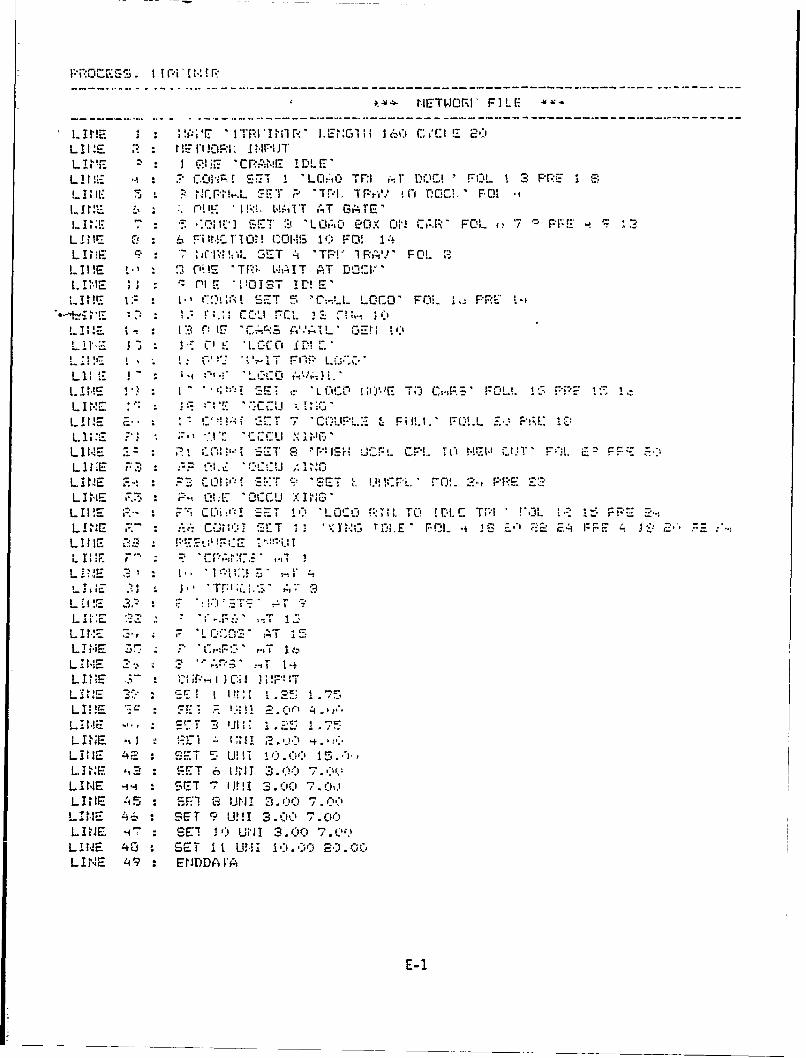
piR 0c E. 1 Pti' P::!-
H ETWORI 'F I L E
1. 1H IEI::i' 1W!-I' M11 R' I.ENIm 11 1 5-) C, ,'c:i E 2-:1LII :s E rPI INPUJTL 1E 1! 2: 3 0:1.* 'CR:-'NE- IOLE'1E 1 1E1fS 1 'L05.:0) TF: I*~DO FOL 1 2 PRE 1 S:!-I; 'Il. aj S NC hL. SET P "I I. *TP.-*?, 0.- FIR. PLI r!"'. WAT ~ A L~IT AT GAT E'Id ..: Q: ,te S . 117E T :-J "LowD SOX 011 CtJ FOL (?7 -'r-!4E :INE Cs 6 F-iRAIR 1k:0!n oIf) FD! 14L I ,E C9 7 !:,.1L SET 0 TP!' I PA' FOL2LI I E V'1 23 ONE mTa WIT AT DOWVLt !',!E i -- Ol E WO!0I1ST IDr! E'LIE. I : M is I R;;M SET 5 C-L OE' Ff'i. 1-:FC1
LII- I~ P~c IF "CARS: Mi.AIL. 001EM
L. 14S VII ''A" ' O 'iL IE1- 1) T* C,!SL1 E : : ,: fl1 .. .. -.-I r'r LU fpt j " '.""
LANE E. * ' 2 .CO7 'AL'I tD :r---. r!-L Z
LW E P3 CIPA :cT C, 'n'-:cc P.mcLI ME M, :X11h ' API -i140'FLLE FLt
LMiE F3 : :. ;C ..,-:g SET S0 '-C- 13K iJOR. TO in EW VHT' L-tI PREL I 'E r ,r ' eLid C-*l',: CC Ai 15NOL E. 2EO F 4 JS2!1
L I!E E" '' ClJitfS:~'E .1' ;L'F'.3~PELIN ,E : ~ 0:C'a g1
LIN&'E 2 'YtlFC :-.TTLIHF! - - L-- ,
L INE ZS! -,T It:)
L I ME 2 ? '.:',T 15-L I! t - '1E 0 iI3 P- IT1L iNE SH 1 U~~. AT "25.7
LINE FL 1A . 1r.; '9LIN1 E SE CiF3- O IMP!.51
L~ ~ ~ 1 E 4S-- T ' !1 1 ': ... C; *11 .'
LIN.E 2 : -.E T 6; Il __. 0'r0 . -LIN E -'' SET 7 'IOU t .00 7ff
L I 'E 5;3 S FG3 131P11 3. 00 7. C00
LIN1 1E AS : SET M U1 3 .00-' 7. 00L INE -17: SE! 2') URI 1 3.0CI 7. AlLI1NE 40 :SET i t [U-, 1 2.C0)C;* C'LI NE 49 : EDDg IFA
E- 1

HETWORI.(' FILE
LlIHE I P; 'r:' iT;ISHIP If - EiIC1H6 ;~~ E 2(
L 1 ilE J CI.-E 'CR'AtiE ID5LE'**m R (_ ~imf! Sr-T 1 2LO~i-) TFR rd r-OfI ' FIOL 1 3 FF-lE 1 8
L 1IL 5 P *rr~.LST~ TF.I: T~r-V) 1 fl f100,' FOiLt-IU HE C'IU. ' W.('AIT AT GATE'L VI:17 7 I SET S 'LO..0 POX~ Olel Ut.R' FOL e)7 PFE k S 12
L A NE 0! 6 FilMUVI0W COMIS 10 FO! 14L I E c? 7 Gf~~s ET 4 'TPV IRAIP F'OL lSLIH E o 132~)Pl 'TP,,- W-A~IT AT rs0C~l
LI HE 1; 't9; G. SET 5 C-'. LOC0' FOL 1. PRE ~v.0 I i 0 r;.,, 1 c IO . l .-CL z 7 v 1._J
L I 1E 'l-t I -( 0 IE Cv. 1:% S GErI 10
LIME . . 1.1 , (* V: -',.:c 1 0 OL1 I ~E 1 I .~ -_ C. ', LYAL. I - c'' TO c. 1 z O l 3 r
LINE 1. ::w SET 'cLCO "E TO Filil.' FOLL 13T'E FIP W
HL~E E: -z 1 IM! SET 7 'SELTA E FOwL'r L -_. P-E E'
L PIE 1; 7, CtI' I S ":T 10 7KLOCO ;:TI. ro CPL Tf TlW CUT" Fij. 2'2 F-
L tE 2: ~ P2 D S*.T S, ISE-7 TrAE. FOL 4 --,- PRE 2 F2, ~2LI vt 12 - P., f: .L:. " c x I
LHE~ 2_ * 1c:3-IT1
LINiE :3 1 in~ in" T 1
LWE ~.2F' S T , W~ T S,~
-LINE 3" OC' ATF 15-L 1'vE I I I t ,T It-1, 71. 1 1E Z? 2 ~ ! -i 1-
LIE J2 *; IE S I i0.o: 1T
LINHE - E~ ET 3 1j1.I 1.20 75LINE JS -F1 1: 1JN -.0 .0
L I t - 4 SE-T Z! 1N :3.00 7.0s)
L LIrE :7 SEI 10 UHI 3.00)C 7.00LINEt 40' SET ll W-1-11 10.60 20.00L IN'E 49 :EHIDDA A-
E- 1

I
i , - - . - -0
I 1 kA d a
I Z
--NtokLoi iga of SigeTakFciiywt rc
tn'
En a ner1i
I- C7
®r1
E tranc J Intrito
-2