rzqordghgiurpzzz wvxsgdwh lq
TRANSCRIPT

Electromagnetic induction
Ativity 9The discovery and understanding of electromagnetic induction are
based on a long series of experiments carried out by Faraday and Henry.Let us try to do one of those experiements.
Connect the terminals of a coil to a sensitiveammeter or a galvanometer as shown in the fig.-13.Normally, we would not expect any deflections of needlein the galvanometer because there is no electromotiveforce in this circuit. Now if we push a bar magnet towardsthe coil, with its north pole facing the coil, a remarkablething happens. While the magnet is moving towards thecoil, the needle in galvanometer deflects, showing that acurrent has been set up in the coil, the galvanometer does
fig-13
N
S
G
N
Class: X Physical Science
Downloaded from www.tsupdate.in

not deflect if the magnet is at rest. If the magnet is moved away from thecoil, the needle in the galvanometer again deflects, but in the oppositedirection, which means that a current is set up in the coil in the oppositedirection.
If we use the end of south pole of a magnet instead of north pole in theabove activity, the experiment works just as described but the deflectionsare exactly reversed.
Further experimentation enables us to understand that the relativemotion of the magnet and coil set up a current in the coil. It makes nodifference whether the magnet is moved towards the coil or the coil towardsthe magnet.
Faraday’s Law“Whenever there is a continuous change of magnetic flux linked with a
closed coil, a current is generated in the coil.”This is one form of Faraday’s law.The current generated is called induced current and is set up by an
induced electromotive force (induced EMF). This phenomenon of gettinginduced current is called electromagnetic induction.
Faraday observed that the changes in the magnetic flux through thecoil are responsible for the generation of current in the coil. He alsoobserved that the rapid changes in flux through coil generate greater inducedcurrent or induced EMF. After observing this important factor, he proposeda law of electromagnetic induction, which is as follow,
“The induced EMF generated in a closed loop is equal to the rate ofchange of magnetic flux passing through it.”
In mathematical form, we can write this as
Induced EMF = change in flux
time
ε = tΔΦΔ
.....................(6)
The equation is called Faraday’s law of induction where Φ (phi) is theflux linked with coil. Let Φ0 be the flux linked with single turn. If there areN turns in the coil, the flux linked with the coil is N Φ0.
Φ = N Φ0 ......................(7)So far we have not specified the direction of the induced EMF or
induced current. In the previous example, we have observed that an inducedcurrent is set up in the loop.• What is its direction?• Can you apply conservation of energy for electromagnetic induction?
Downloaded from www.tsupdate.in

Lenz LawWhen we push the bar magnet towards the coils, current is generated,
in other word electromagnetic induction takes place and mechanical energyis converted into electrical energy.
Let us discuss it in detail.We know that when a bar magnet is pushed towards a coil with its
north pole facing the coil an induced current is setup in the coil. Let the direction of current in thecoil be in clockwise direction with respect to northpole of the bar magnet. Then this current carryingloop behaves like a magnet, with its south polefacing the north pole of bar magnet. In such a case,the bar magnet attracts the coil. Then it gains kineticenergy. This is contradictory to conservation ofenergy. So our assumed clockwise direction of
induced current is wrong. Hence the correct direction of induced currenthas to be in anticlockwise direction with respect to north pole of the barmagnet. In such a case, the north pole of the coil faces the north pole ofthe bar magnet as shown in figure 14. Then north pole of bar magnet isrepelled by the north pole of the coil. Hence we need to do work toovercome this force. This work done on the magnet is converted intoelectrical energy in the coil. In this way conservation of energy takes placein electromagnetic induction.
Let us see a case where the bar magnet is pulled away from the coil,with north pole facing the coil. In such case, the coil opposes the motionof bar magnet to balance the conversion of mechanical energy into electricenergy. This happens only when the north pole of the magnet faces thesouth pole of the coil.• Can you guess what could be the direction of induced current in the
coil in such case?Invariably the direction of induced current in the coil must be in anti
clock wise direction. In simple terms, when flux increases through coil,the coil opposes the increase in the flux and when flux decreases throughcoil, it opposes the decrease in the flux. This is discovered by a RussianPhysist Heinrich Lenz.
Lenz’s law states that “the induced current will appear in such adirection that it opposes the changes in the flux in the coil.”• Could we get Faraday’s law of induction from conservation of energy?
fig-14
N
NN
NN
S
SSSS
N S
Downloaded from www.tsupdate.in
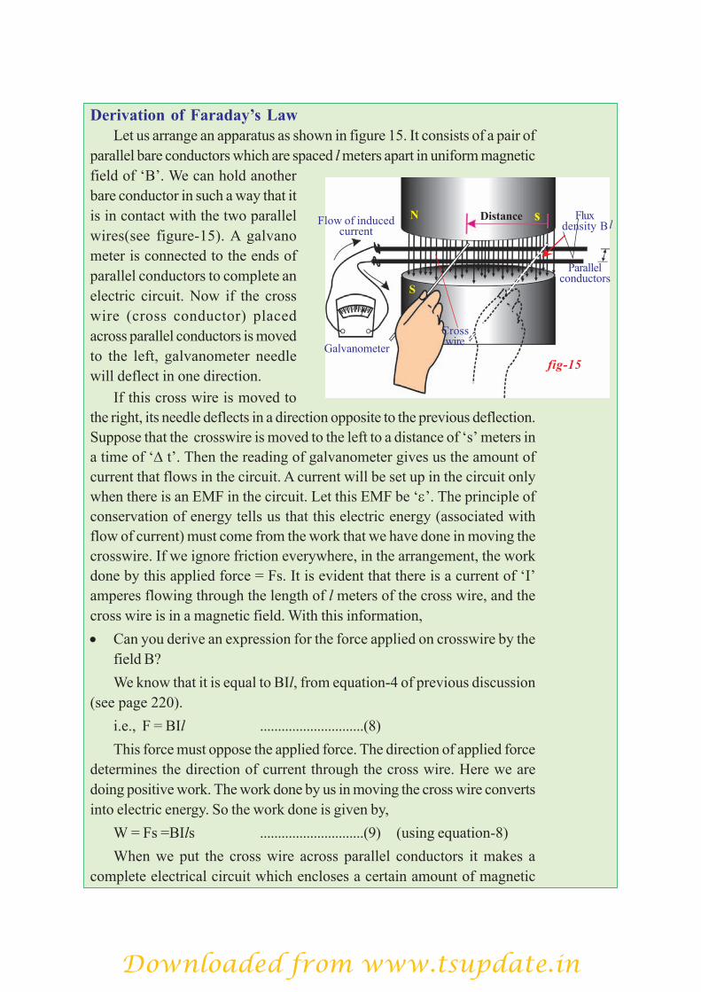
Derivation of Faraday’s LawLet us arrange an apparatus as shown in figure 15. It consists of a pair of
parallel bare conductors which are spaced l meters apart in uniform magneticfield of ‘B’. We can hold anotherbare conductor in such a way that itis in contact with the two parallelwires(see figure-15). A galvanometer is connected to the ends ofparallel conductors to complete anelectric circuit. Now if the crosswire (cross conductor) placedacross parallel conductors is movedto the left, galvanometer needlewill deflect in one direction.
If this cross wire is moved tothe right, its needle deflects in a direction opposite to the previous deflection.Suppose that the crosswire is moved to the left to a distance of ‘s’ meters ina time of ‘Δ t’. Then the reading of galvanometer gives us the amount ofcurrent that flows in the circuit. A current will be set up in the circuit onlywhen there is an EMF in the circuit. Let this EMF be ‘ε’. The principle ofconservation of energy tells us that this electric energy (associated withflow of current) must come from the work that we have done in moving thecrosswire. If we ignore friction everywhere, in the arrangement, the workdone by this applied force = Fs. It is evident that there is a current of ‘I’amperes flowing through the length of l meters of the cross wire, and thecross wire is in a magnetic field. With this information,• Can you derive an expression for the force applied on crosswire by the
field B?We know that it is equal to BIl, from equation-4 of previous discussion
(see page 220).i.e., F = BIl .............................(8)This force must oppose the applied force. The direction of applied force
determines the direction of current through the cross wire. Here we aredoing positive work. The work done by us in moving the cross wire convertsinto electric energy. So the work done is given by,
W = Fs =BIls .............................(9) (using equation-8)When we put the cross wire across parallel conductors it makes a
complete electrical circuit which encloses a certain amount of magnetic
fig-16
N s
S
Galvanometer
Flow of inducedcurrent
Distance Fluxdensity B
Crosswire
l
Parallelconductors
fig-15
Downloaded from www.tsupdate.in

flux. Now as we move the cross wire to the left, the area of the loop (formedby the parallel conductors and cross wire) decreases and the flux throughthe loop also decreases. The decrease in flux is given by,
ΔΦ = Bls .............................(10)Here B is perpendicular to the area (ls). From equations 9 and 10W = (ΔΦ) ΙLet us divide both sides of this equation by Δt
WtΔ
= I
tΔΦΔ
.............................(11)
Electric power, P = I
tΔΦΔ
We know that electric power is the product of current and emf or
voltage. ε= tΔΦΔ
is obviously equal to induced EMF.
Electric power, P = εΙ .............................(12)Thus the electric power generated in the circuit is equal to product of
induced EMF and the current. Thus the mechanical energy utilised to move
the cross wire in one second is converted into electric power tΔΦΔ
I. This
is nothing but conservation of energy.Dividing equation (9) by Δt, we have
WtΔ
= Fs
tΔ =
BIlstΔ
..................(13)
Here stΔ
gives the speed of the cross wire, let it be taken as v. Then we
get, Electric power P = W
tΔ= Fv = BIlv ......(14)
Power is also given as force times velocity. From equations (12) and
(14), we get W
tΔ = εI ⇒ εI = BIlv
We get, ε = Blv This is called motional EMF. The above equation is not Faraday’s law of induction because it is not
related to the loop. It is useful when a conductor moves in a uniformmagnetic field.
Downloaded from www.tsupdate.in

Let us see a few examples on induced emf.Example 1
The magnetic flux inside a coil of 400 turnschanges for each single turn with time as shown infigure
Determine the maximum induced emf generatedin the coil. Is there any change in induced EMF fromt = 0.1 second to 0.3 second?
Solution: From the given graph, the increase inmagnetic flux through one turn of coil in 0.1 second is 0.001 Wb. Accordingto Faraday’s law, the maximum induced emf generated in the coil is givenby,
ε = N tΔΦΔ
Substituting the values, we get
ε = 400 0.001
0.1×
= 4V
From graph, there is no change in magnetic flux through coil fromt = 0.1s to 0.3s hence no emf is generated.
Example 2Find the length of the conductor which is moving with a speed of 10
m/s in the direction perpendicular to the direction of magnetic field ofinduction 0.8T, if it induces an emf of 8V between the ends of theconductor.
Solution: Given that B = 0.8T, v = 10 m/s and ε = 8V.Using ε = Blv 8 = 0.8(l)(10) l (length of the conductor) = 1m
Applications of Faraday’s law of electromagnetic inductionElectromagnetic induction is all around us.
• You might have seen that, during security check, people are made towalk through a large upright coil of wire which produces a weak AC(alternating) magnetic field. If we are carrying any significant quantitiesof iron, the magnetic flux linked with the large coil changes and theinduced current generated in coil triggers an alarm.
• The tape recorder which we use to listen to songs (or) record voicesworks on the principle of electromagnetic induction. It consists of apiece of plastic tape coated with iron oxide and is magnetised more in
fig-E-2
Downloaded from www.tsupdate.in
some parts than in others. When the tape is moved past as a small coilof wire (head of the tape recorder), the magnetic field produced bythe tape changes, which leads to generation of current in the smallcoil of wire.
• How could we use the principle of electromagnetic induction in thecase of using ATM card when its magnetic strip is swiped through ascanner? Discuss with your friends and your teacher.
• An induction stove works on the principle of electromagneticinduction. A metal coil is kept just beneath the cooling surface. It carriesalternating current (AC) so that AC produces an alternating magneticfield. When you keep a metal pan with water on it, the varying magneticfield beneath it crosses the bottom surface of the pan and an EMF isinduced in it. Because the pan is metal the induced EMF generates aninduced current in it. Since the pan has a finite resistance, the flowinduced current in it produces heat in it and this heat is conducted tothe water. That’s why we call this stove as induction stove.Have you ever thought, from where do we get electrical energy?Let us learn about it.
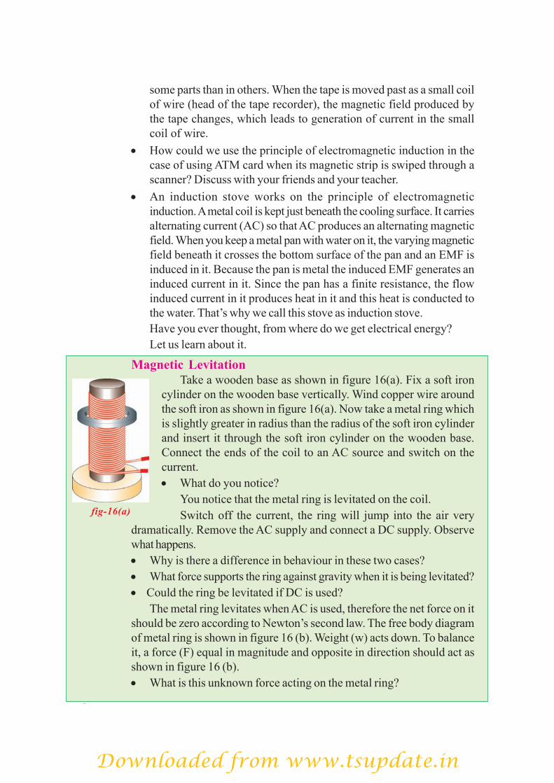
Magnetic LevitationTake a wooden base as shown in figure 16(a). Fix a soft iron
cylinder on the wooden base vertically. Wind copper wire aroundthe soft iron as shown in figure 16(a). Now take a metal ring whichis slightly greater in radius than the radius of the soft iron cylinderand insert it through the soft iron cylinder on the wooden base.Connect the ends of the coil to an AC source and switch on thecurrent.• What do you notice?
You notice that the metal ring is levitated on the coil.Switch off the current, the ring will jump into the air very
dramatically. Remove the AC supply and connect a DC supply. Observewhat happens.• Why is there a difference in behaviour in these two cases?• What force supports the ring against gravity when it is being levitated?• Could the ring be levitated if DC is used?
The metal ring levitates when AC is used, therefore the net force on itshould be zero according to Newton’s second law. The free body diagramof metal ring is shown in figure 16 (b). Weight (w) acts down. To balanceit, a force (F) equal in magnitude and opposite in direction should act asshown in figure 16 (b).• What is this unknown force acting on the metal ring?
fig-16(a)
Downloaded from www.tsupdate.in

In this activity AC is used. AC changes both its magnitude anddirection in regular time intervals. We know that the current throughthe coil, produces a magnetic field so that one end of the coil behaveslike north pole and other end behaves like south pole for a certaintime interval. For the next interval, coil changes its polarities.Hence we can say that coil undergoes changes in its poles in thesame intervals of time. The levitation of metal ring is possibleonly when the metal ring behaves like a magnet and should changeits polarities in the same time intervals but in a sense opposite to that of thesolenoid (coil) as shown in figure 16(c). Assume that the current flows in anclockwise direction in the solenoid as viewed from the top. Then the upperend becomes a south pole. An upward force is applied on the ring only whenthe upper side of the ring becomes a north pole (i.e. south pole of the ringfaces towards the south pole of solenoid). It is only possible when thereexists a anticlockwise current (viewed from the top) in the ring. After certainintervals, solenoid changes its polarities, so that the ring should also changeits polarities in the same intervals. This is the reason why the metal ring islevitated.• What is responsible for the current in the metal ring?
AC is not a constant current. So that, the magnetic induction changesin both magnitude and direction in the solenoid and in the ring.
Here the area of the metal ring is constant. But the field through themetal ring changes so that flux linked with the metal ring changes.• If DC is used, the metal ring lifts up and falls
down immediately. Why?The flux linked with metal ring is zero when
no current flows through the solenoid. When thecurrent is allowed to flow through the solenoid,it behaves like bar magnet. So the flux is linkedto the metal ring when the switch is on. At thatinstant there is a change in flux linked with ring.Hence the ring rises up. There after, there is nochange in flux linked with coil, hence it fallsdown. If the switch is off, the metal ring againlifts up and falls down. In this case also, there is a change in flux linkedwith ring when the switch is off.• What could you conclude from the above analysis?
Electric Generator and Alternating - Direct Currents• What happens when a coil is continuously rotated in a uniform magnetic
field?• Does it help us to generate electric current?
fig-16(b)
F
W
Direction ofinduced emf
Falling ring
fig-16(c)
Downloaded from www.tsupdate.in

Let us see:Consider a rectangular coil. Let it be held
between the poles of Curve- shapedpermanent magnet as shown in fig.-17(a). Asthe coil rotates, the magnetic flux passingthrough the coil changes. According to the lawof electro magnetic induction an inducedcurrent is generated in the coil.• Is the direction of current induced inthe coil constant? Does it change?
1. Consider initially the coil, positionedin such a way that magnetic flux passesthrough it. When the coil is at rest in verticalposition, with side A of coil at top positionand side B at bottom position, no current will
be induced in it. Thus current in the coil is zero at this position.2. When the coil is rotated in clockwise direction, current will be
induced in it and it flows from A to B. During the first quarter of rotation,the current increases from zero to a maximum and reaches peak valuewhen the coil is in horizontal position.
3. If we continue the rotation of coil, current decreases during thesecond quarter of the rotation and once again becomes zero when coilcomes to vertical position with side B at top A at bottom position. Duringthe second part of the rotation, current gener-ated follows the same patternas that in the first half except that the direction of current is reversed.
(see fig.-17(b))• Can you guess thereason for variation ofcurrent from zero tomaximum and vice-versaduring the rotation of coil?• Can we make use of thiscurrent? If so, how?
Let us find out.As shown in fig.-17(a)
the ends of the coil areconnected to two sliprings. Two carbon brushesarranged in such a way that
Slip rings
Brushes
N
SA
B
Rotation
fig-17(a):AC Generator
emf g
ener
ated
in th
e co
il One complete cycle
Zero emfcoil
vertical
Maximumemf, coil
horizontal
Zeroemf
Maximumreversed
emf
Zeroemf
Position of coil in one rotation.
No. ofrevolutions
0 1
fig-17(b)
B
A
AB
B
A
AB
B
A
AB
14
12
34
114
B
Downloaded from www.tsupdate.in

they press the slip rings to obtain current fromthe coil. When these brushes are connected toexternal devices like TV, radio, we can makethem work with current supplied from ends ofcarbon brushes.
The current obtained by this processchanges its direction alternatively for each halfcycle as shown in fig.-17(b).
This current is called alternating current(AC) in which, the direction of charge flowreverses periodically. So AC possesses certainfrequency. The generator that we discussedhere is called AC generator.• How can we get DC current using a
generator?• What changes do we need to make in an AC generator to be converted
into a DC generator?Let us find out.If two half slip rings are connected to ends of the coil as shown in
fig.-17(c), the AC generator works as DC generator to produce DC current.Let us see how it works.When the coil is in the vertical position the induced current generated
during the first half rotation, rises from zero to maximum and then falls tozero again. As the coil moves further from this position, the ends of thecoil go to other slip rings. Hence during the second half rotation, thecurrent is reversed in thecoil itself, the currentgenerated in the second halfrotation of the coil isidentical with that during thefirst half of direct current(DC) as shown in fig.-17(d)for one revolution.
In generators,mechanical energy isconverted into the electricalenergy.
Commutator
Brush
N
S
Rotation
R
A
B
fig-17(c):DC Generator
114
12
34
114
emf g
ener
ated
coil
Zero emf Maximumemf
Zeroemf
Maximumemf
Zeroemf
No. ofrevolutions
0
fig-17(d)
Position of coil in one rotation.
B
A
AB
B
A
AB
A
AB
B
B
Downloaded from www.tsupdate.in

Key words
Magnetic flux, Magnetic flux density, Electric motor, Slip rings,Induced current, Induced EMF, Electric generator, DC andAC currents, rms values
• A measure of strength of magnetic flux by taking account of number of field lines iscalled magnetic flux.
• Magnetic flux density (B) is defined as the ratio of flux passing through a plane perpendicular tofield and the area of the plane.
• Current carrying wire produces magnetic field.• F = qvB sinθ and F = ILB sinθ• In electric motor, electrical energy is converted into mechanical energy.• The production of electric current due to relative motion between a coil and a magnetic field is
called electromagnetic induction.• Faraday’s law: The induced EMF generated in a closed loop is equal to the rate of change of
magnetic flux passing through it.• Lenz’s law: the induced current set up in the coil is in such a direction that it opposes the changes
in the flux.• When a conductor of length ‘l’ moves perpendicular to field B with a speed v then potential
difference (voltage) developed between the ends of conductor is Blv. This EMF is called motionalEMF.
• In generators, mechanical energy is converted into electrical energy.
Reflections on Concepts1. Are the magnetic field lines closed? Explain. (AS1)
2. See fig-Q2, magnetic lines are shown. What is the direction of the current flowingthrough the wire?(AS1)
3. A bar magnet with North Pole facing towards a coil moves as shown infig-Q3. What happens to the magnetic flux passing through the coil?(AS1)
What we have learnt
Improve your learning
fig- Q2
N
fig- Q3
Downloaded from www.tsupdate.in
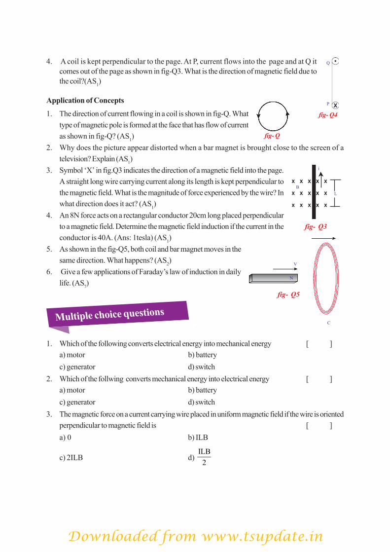
4. A coil is kept perpendicular to the page. At P, current flows into the page and at Q itcomes out of the page as shown in fig-Q3. What is the direction of magnetic field due tothe coil?(AS1)
Application of Concepts
1. The direction of current flowing in a coil is shown in fig-Q. Whattype of magnetic pole is formed at the face that has flow of currentas shown in fig-Q? (AS1)
2. Why does the picture appear distorted when a bar magnet is brought close to the screen of atelevision? Explain (AS1)
3. Symbol ‘X’ in fig.Q3 indicates the direction of a magnetic field into the page.A straight long wire carrying current along its length is kept perpendicular tothe magnetic field. What is the magnitude of force experienced by the wire? Inwhat direction does it act? (AS1)
4. An 8N force acts on a rectangular conductor 20cm long placed perpendicularto a magnetic field. Determine the magnetic field induction if the current in theconductor is 40A. (Ans: 1tesla) (AS1)
5. As shown in the fig-Q5, both coil and bar magnet moves in thesame direction. What happens? (AS2)
6. Give a few applications of Faraday’s law of induction in dailylife. (AS7)
1. Which of the following converts electrical energy into mechanical energy [ ]a) motor b) batteryc) generator d) switch
2. Which of the follwing converts mechanical energy into electrical energy [ ]a) motor b) batteryc) generator d) switch
3. The magnetic force on a current carrying wire placed in uniform magnetic field if the wire is orientedperpendicular to magnetic field is [ ]a) 0 b) ILB
c) 2ILB d) ILB
2
Multiple choice questions
fig- Q3
B
i
L
fig- Q5
N
V
C
xP
Q
fig- Q4
fig- Q
Downloaded from www.tsupdate.in

4. One Tesla = [ ]a) Newton/Coloumb b) Newton / ampere - meterc) Ampere / meter d) Newton / ampere second
5. Magnetic flux [ ]a) dyne b) Oersterd c) Guass d) Weber
6. No force works on the conductor carrying electric current when kept [ ]a) parallel to magnetic field b) perpendicular to magnetic fieldc) in the magnetic field d) away from magnetic field
Suggested Experiments
1. Explain with the help of two activities that current carrying wire produces magnetic field. (AS3)2. How do you verify experimentally that the current carrying conductor experiences a force
when it is kept in magnetic field? (AS3)3. Explain Faraday’s law of induction with the help of activity. (AS3)4. What experiment do you suggest to understand Faraday’s law? What instruments are
required? What suggestions do you give to get good results of the experiment? Giveprecautions also. (AS3)
5. How can you verify that a current carrying wire produces a magnetic field with the help ofan experiment? (AS3)
Suggested Projects
1. Collect information about generation of current by using Faraday’s law. (AS4)2. Collect information about material required and procedure of making a simple electric
motor from internet and make a simple motor on your own. (AS4)3. Collect information of experiments done by Faraday. (AS4)
Downloaded from www.tsupdate.in