ryan - model airplane news · ryan 1 had seen in sig's photo pak. it had a lot of color a eye...
TRANSCRIPT
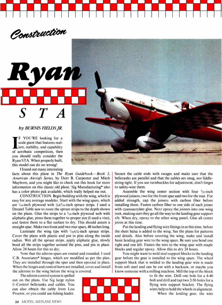
RyanSTAby BURNIS FIELDSJR.
IF YOU'RE looking for ascale giant that features real-ism, stability, and capability
of aerobatic competition, thenyou should really consider theRyan STA. When properly builthis model can do no wrong!
I found out many interestingfacts about this plane in The Ryan Guidebook—Book 3,American Aircraft Series, by Dorr B. Carpenter and MitchMayborn, and you might like to check out this book for moreInformation on this classic old plane. Sig Manufacturing* alsohas a color photo pak available, which really helped me out.
CONSTRUCTION. Begin building with the wing, which iseasy for any average modeler. Start with the wing spars, whichare 1/16-inch plywood with 1/4X5/16-inch spruce strips. I used aDremel Table saw to mute the spruce strips to the depth shownon the plans. Glue the strips to a '/i6-inch plywood web withaliphatic glue, press them together to proper size (I used a vise),and fasten them to a flat surface to dry. This should assure astraight spar. Make two front and two rear spars, 48 inches long.
Laminate the wing tips with '/ifix'/rinch spruce strips.Cover the plans with plastic and put in pins along the insideradius. Wet all the spruce strips, apply aliphatic glue, slowlybend all the strips together around the pins, and pin in place.Allow 24 hours for this to dry.
Note that the aileron spars are routed and rounded. 1 usedC.B. Associates* hinges, which are modified as per the plan.They are installed through the spar and then epoxied in place.When the hinges and control hörn are installed, cover and installthe ailerons to the wing before the wing is covered.
The aileron control System is spelledout on the plans. Use Sig large nylonU-Control bellcranks and cables. Youcan also obtain the cable from LouProctor, or you could use fishing leader.
20 MODEL AIRPLANE NEWS
Secure the cable ends with swages and make sure that thebellcranks are parallel and that the cables are snug, not fiddle-string tight. If you use turnbuckles for adjustment, don't forgetto safety-wire them.
Assemble the wing center section with four 3/32-inchplywood joiners, two for the front spar and two for the rear. Foradded strength, cap the joiners with carbon fiber beforeinstalling them. Fasten carbon fiber to one side of each joinerwith cyanoacrylate glue. Next epoxy the joiners into one wingroot, making sure they go all the way to the landing gear supportrib. When dry, epoxy to the other wing panel. Glue all centerjoints at this time.
Put the landing and flying wire fittings in at this time, beforethe sheet balsa is added to the wing. See the plans for patternsand details. Also before covering the wing, make and installbasic landing gear wire to the wing spars. Be sure you bend oneright and one left. Fasten the wire to the wing spar with mapleblocks and regulär epoxy. Allow this to dry 24 hours.
You might want to weld steel support blocks to the landinggear before the gear is installed to the wing spars. The wheelsupport block that is welded to the landing gear wire is madefrom soft steel and can be cut with a hacksaw, or maybe youknow someone with a milling machine. Mill the top of the block
to fit the wire. Drill one hole for a 4-40bolt and drill and tap two 2-56 holes for aflying wire support bracket. The flyingwires help to hold the wheels in alignment.
When the landing gear, the wire
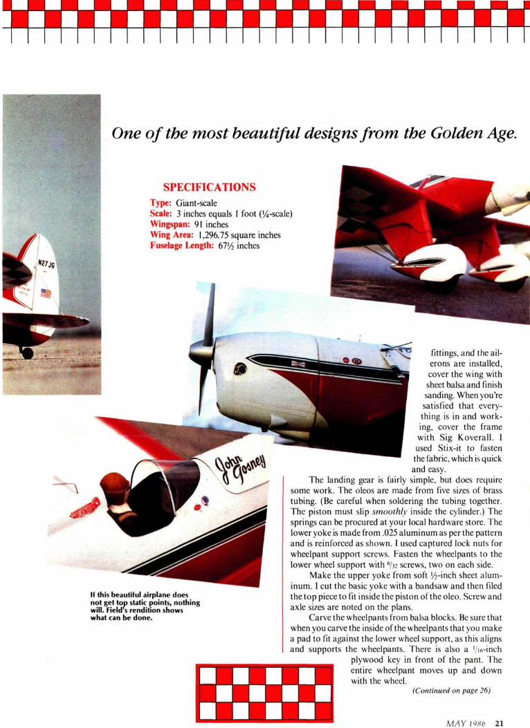
One of the most beautiful designsfrom the Golden Age.
SPECIFICATIONSType: Giant-scaleScale: 3 inches equals 1 foot ('/4-scale)Wingspan: 91 inchesWing Area: 1,296.75 Square inchesFuselage Length: 671/2 inches
If this beautiful airplane doesnot get top static points, nothingwill. Field s rendition showswhat can be done.
fittings, and the ail-erons are installed,cover the wing withsheet balsa and finishsanding. When you'resatisfied that every-thing is in and work-ing, cover the framewith Sig Koverall. 1used Stix-it to fastenthe iabric, which is quickand easy.
The landing gear is fairly simple, but does requiresome work. The oleos are made from five sizes of brasstubing. (Be careful when soldering the tubing together.The piston must slip smoothly inside the cylinder.) TheSprings can be procured at your local hardware störe. Thelower yoke is made from .025 aluminum as per the patternand is reinforced as shown. I used captured lock nuts forwheelpant support screws. Fasten the wheelpants to thelower wheel support with 6/32 screws, two on each side.
Make the upper yoke from soft 1/2-inch sheet alum-inum. 1 cut the basic yoke with a bandsaw and then filedthe top piece to fit inside the piston of the oleo. Screw andaxle sizes are noted on the plans.
Carve the wheelpants from balsa blocks. Be sure thatwhen you carve the inside ofthe wheelpants that you makea pad to fit against the lower wheel support, as this alignsand supports the wheelpants. There is also a '/ih-inch
plywood key in front of the pant. Theentire wheelpant moves up and downwith the wheel.
(Continued on page 26)
MAY 1986 21
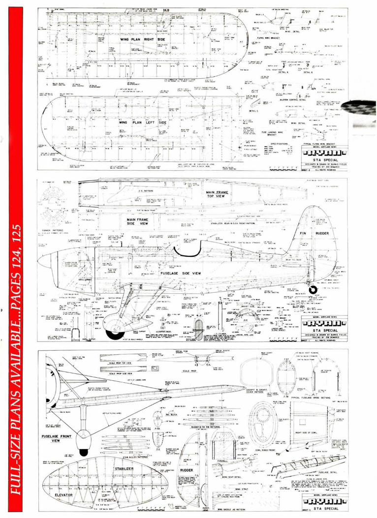
WING PLAN LEFT SIDE .
FUSE LANDING Wll
STA SPECIAL
STA SPECIAL

(Continued from page 21)covered, and would be almost unseen.
Pay attention to the way the balsa andplywood parts go together at the nosc.They give plenty of beef to the nose, butyou don't want any unnecessary noseweight.
Laminate the fuselage sides with onesheet of 1/4-inch balsa and one of ' Vinchbalsa. You'll want to use light quarter-
Left and below, shockabsorbing landinggear setup.
The fuselage is quite easy to build, butpay close attention to the firewall andlanding wire support. I started to usespruce for the longerons, but, due to theconstruction method, spruce is notneeded. You might like to build in atunnel in the lowcr front of the fuselareto help cool the engine. This would bevery simple to do before the lower nose is
grain balsa for this. I used Sigment tobuild the fuselage, except for the firewalland landing gear support, which 1epoxied in. Keep the structure light.Sand the completed fuselage to shape,and cover with Koverall or similar fabric.
You'll notice that the Quadra .35engine is tilted slightly to clear the cowl.The plastic piece on the carburetor isremoved and a couple of washers put inits place. Don 'tforget the washers or youcould dimple the cylinder.
Carve the cowl from balsa. Start witha balsa support egg-crated together andfitted between the front and rear '•ih-inchplywood guide rings. Cut the balsa sup-port to the shape of the side view andthe top view at the centerline of thefuselage. Once these four pieces havebeen assembled and aligned, fill inaround the outside with 21/2X3/4-inchStrips of sheet balsa. Taper the strips tofit together and set in 1/4-inch from theedge of the plywood. Add a block to thefront of the assembly, and carve andsand to shape. Cut the inside of the cowlto slide over the fuselage sides, as thiscutout holds the cowl in position.
Fiberglass parts for the STA can either be formed as described in text or obtained from Fiberglass Master.
MAY 27

The cowl is held to the fuselage withone bicycle spoke and thimble. Make abrass bracket that will fasten to the coilscrew and solder the bicycle spoke to thebracket. The spoke sticks through thecowl just below the crankshaft. If youVedone the job right, the cowl will fit verysnugly and will not vibrate.
Carve the air scoops from scrap balsa.The scale metal overlay is made from
thin heat-forming plastic obtained fromSig. The exhaust stacks are brass tubing.
The tail is very basic. Cut the ribs andthe spars from light C-grain balsa.Laminate all outlines the same as on thewing tips and allow to dry thoroughly.Cut all notches. Fasten the spars flat on atable with the notches up. Install the ribsin the notches with Sigment or anequivalent. Add the leading edge and
Ryan STA Special
RYAN AERONAUTICAL COMPANY located at Lindbergh Fieldin San Diego, California, first developed the Ryan ST. Although itwas a beautiful classic airplane, and even though crowds were
drawn to its beauty and performance, not everyone wanted to own it.Because of this, Ryan came up with a new version with more horsepowerand a supercharged Menasco C4S engine and called it the Ryan "STASpecial."
The Ryan STA was a low-wing open-cockpit monoplane, which wasspecially custom-crafted for high performance at higher altitudes. Thisairplane was one of the handsomest in the sky: slender, sleek, trim, and veryperky.
As the STM (an export version of the military), it served on trainingand tactical missions. With the Menasco C4S engine of 150 hp, theperformance increased as it went higher.
The STA was an all-around eye-opener with a personality of its own. Itwas easy to fly, predictable, and highly maneuverable. Maintenance wasminimal and operating costs were fairly low. The Ryan STA Specialreceived its type certificate retroactively to October 30, 1937.
1 had been researching for a 1/4-scale aerobatic plane to build and ranacross some photos of the Ryan STA Special. (I'm very interested in both1/4-scale and I MAC aerobatics and this plane would do both.) Many STAplanes were silver or chrome, but then I saw photos of the one owned byJohn Ciosney, which has a 200-hp Menasco engine. It was red, white, andblack and just jumped out at me. I wrote to Maxey Hester of Sig who hadbuilt a smaller version some years ago and he sent me a photo pak of theactual plane. The full-scale airplane had an overall length of 21 feet, 6inches; a wingspan of 19 feet, 11 inches; a wing chord of 56 inches, and atotal wing area of 124 square feet. The Special had an empty weight of 1,058pounds and a gross weight of 1,600 pounds. It looked better and better as apotential model for both scale and aerobatics, which 1 like to combine. Thiswas the deciding factor in my going with the Ryan STA Special. •
check for alignment. Allow to dry andsand to finished shape. Cover the tailsurfaces with Koverall or similar mater-ial. I use Koverall because it is light andstrong, and, above all, holds paint verywell. It also fills quickly.
Make the tail fairings from heat-forming plastic and install them with #0wood screws, which do the job well andlook scale.
For covering 1 used Sig's aluminumfabric with silver dope and then paintedthe model red, white, and black after aRyan 1 had seen in Sig's photo pak. Ithad a lot of color a eye appeal.
My Ryan STA was a little nose-heavy,so I added 8 ounces of lead to the tailpost. Be sure the model balances pro-perly. It won't hurt if it's a little nose-heavy at first. The prototype weighed inat only 15 pounds ready to fly.
The Ryan STA on the wing is a beautifulsight to behold.
FLYING. The model flew right off theboard and was very smooth handling. Alittle back pressure on the stick and alittle right rudder, and she was airbornea real sight to see!
I've done loops, rolls, snap rolls,Cuban 8s, and humpty bumps.
When you come in for a landing, keepa little power on. Practice will show youhow much.
You'll really be proud of this plane. Itis sheer pleasure to fly and a winner onthe contest trail!
* The following are the addresses of thecompanies mentioned in this article:
Sig Mfg. Co.. Montezuma, IA 50171.C.B. Associates, Inc., 21658 Cloud Way.
Hayward. CA 94545. •
28 MODEL AIRPLANE NEWS