ry io tinklo spint saugumas - · pdf filebiometric legic any deviation from the ... digital...
TRANSCRIPT

SecurityMonitoring system CMC-TC
806 Rittal Catalogue 32/IT Solutions
B
5.6
Se
cu
rity
Security – individual and flexible
The CMC-TC offers a new dimension in flexibility, efficiency,
technology and cost-effectiveness. The modular master/slave
system uses network technology as its communication
system. In the past, bus systems were used for this purpose,
but the CMC-TC system uses TCP/IP and SNMP for
The new wireless sensor tech-nology unites the popular CMC-TC system with radio sensors. This transports the modular concept into a new dimension of flexibility. Existing IT infrastructures can also be easily retrofitted with the wire-less sensor network.
Detailed information, see page 834.
Now with wireless
sensor technology
2.4 GHz!
Processing Unit PU II
Sensor unit
Master II
Racks with sensors/actuators, access, climate and power
Sensor unit
Processing Unit PU II
Processing Unit PU II
Central monitoring and administration
Sensor unit
Processing Unit PU II
communication between the Master and Processing Unit II.
This gives users the option of working with high performance,
i. e. the CMC-TC Master, or only with the Processing Unit II.
The standardised interface on the Processing Unit II (PU II)
allows even small individual applications to be achieved
cost-effectively. The Master II may also be used.
Sensor unit
LAN

Monitoring components
Security
807Rittal Catalogue 32/IT Solutions
B
5.6
Se
cu
rity
Protection against data misuse is one of the most vital security factors in any company. The CMC-TC system regulates access to the server racks and records access. Access Vandalism
Magnetic card Numerical code
Transponder Smart card
Biometric Legic
Any deviation from the setting is logged. The CMC-TC monitors the climate control components.
Monitoring of icing
Monitoring of filter mat
Speed control Leakage detection
Temperature control
Airflow monitoring
CMC-TC logs all safety-relevant parameters on the inside and the outside of the rack using various sensors.
Temperature monitoring
Monitoring of humidity
Individual, analog input
Smoke monitoring
Individual, open, digital input
Individual relay output
The CMC-TC monitors voltages and currents, and controls the power supply for individual network compo-nents.
Power supply Power control
Overvoltage protection
Voltage measurement
Current measurement
Security: Access Rack
Cooling Power

SecurityMonitoring system CMC-TC
808 Rittal Catalogue 32/IT Solutions
B
5.6
Se
cu
rity
0°0°
The CMC-TC monitoring system is the complete security management concept for preventive protection, to guard against
follow-on costs. At the same time, it is also the central organisational unit for connecting to facility management.
Processing Unit II (PU II) forms the basis of any application and provides a direct interface to the user network. The sensor
units are linked to the PU II with various sensors. The function of the CMC-TC monitoring system is determined by the
selection of sensor units and sensors.
PLC X2
RTT I/O
unit
G+
-
RS-485
LANCOM
RS-232
Processing Unit II (PU II): The nerve centre of the monitoring system CMC-TCThe PU II serves as a coordinator between the sensor unit and the network. It is con-figured via the integral web server.
Active Power System Module PSM, Power Control Unit PCUThe sockets may be activated directly by the Processing Unit II, combined with an ammeter (max. 4 x 4 x 8 sockets).
RTT I/O unitUp to 10 climate control devices with Comfort controller may be connected via one unit in master/slave mode.
Liquid Cooling Package LCPThe professional LCP water cooling system for data centres may be linked directly to the Processing Unit II.
0˚0˚ 0˚0˚
I/O unit wirelessUp to 16 sensors may be wirelessly incorporated into the CMC-TC system via this unit.
Electronic systems with monitoring of temperatures, fans and DC voltages, see page 502.
LAN (SNMP/WEB)GSM (SMS)ISDN (SMS)ISDN/analog modem pointto point (SNMP/WEB)
Access unit The doors of buildings, rooms and enclosures may be moni-tored, activated and opened via the network.
Climate unit, Fan Control System FCSFans are controlled via tempera-ture sensors. Airflow monitors report any contamination of the filter mat, for example. The fan speed is controlled and moni-tored via the FCS.
Universal I/O unit This measurement and alarm module indicates motion, vibrations, doors being opened, temperatures exceeded, and much more besides. The sensors may be selected for the application.

Basic module
Security
809Rittal Catalogue 32/IT Solutions
B
5.6
Se
cu
rity
Monitoring system CMC-TC Processing Unit II The Processing Unit II forms the basis of the CMC-TC system. This unit is required for every monitoring application.
Benefits: ● Freely selectable monitoring functions● Sensor/actuator ports extendible● TCP/IP SNMP network connection● Integral web server for configuration● Automatic menu generation● Simple installation based on the plug & play
system● Alarm continues to record even in the event of
a network failure● Built-in real-time clock with NTP ● May be used via power pack for 100 – 240 V AC
or 48 V DC● Choice of mounting on the enclosure frame or
482.6 mm (19″) mounting angles● Master II interface TCP/IP SNMP● May be used for large data centres or small
individual applications
Interface to the customer: The PU II can be incorporated directly into the user network via 10/100BaseT. The PU II can also be linked to the master DK 7320.005 via this inter-face (TCP/IP, SNMP).
Interface to the sensors/actuators: The PU II provides 4 open ports for sensor units. The sensor units determine the function of the PU II. There is a choice of 12 sensor units with different functions. In this way, the monitoring functions may be freely combined.
Fast, easy programming and installation: The sensors/actuators are set up via an auto-matic electronic ID system. Installation is via a flexible plug & play system. This eliminates the need for time-consuming programming and wiring.
Power supply:Power is supplied centrally via a power pack in the PU II. The connected sensor units and all connected sensors are supplied with power in this way. There is a choice of two input voltages (AC power pack DK 7320.425 and DC power pack DK 7320.435).
Also required:
Sample configuration, see page 806. Connection cable DK 7320.470,see page 819.
CCMC-TC
Processing Unit
1 2 3 4
IOIOI
1 2 3 7654
1 12
3 4
Power
P-I2CIOIOI
24 V DCmax. 2 A
8 9 10 11 12
Model No. DK 7320.100
W x H x D mm 136 x 44 (1 U) x 129
Network interfaceEthernet to IEEE 802.3 via 10BaseT/100BaseT, 10/100 Mbit/s
Protocols
TCP/IP, SNMP V1.0, Telnet, Secure Shell SSH, FTP, HTTP, HTTPS with SSL, Network Time Protocol NTP, DHCP, PPP, SMTP, SFTP, SNMPv3
Rated voltage 24 V DC
Serial interfaces RS-232
Ports for sensor units
4 jacks RJ 45, shielded
Bus systemPower I2C for extension unit voltage AC DK 7200.520
Alarm relay output
Change-over contact max. 24 V DC 1 A
Audio display Piezo signal generator
Time function Real-time clock
Temperature application range
+5°C to +45°C
Humidity applica-tion range
5 % to 95 % relative humidity, non-condensing
IP protection category
IP 40 to EN 60 529/09.2000
Control key The C key is for sensor/actua-tor identification, set-up of the system and acknowledge-ment.
Alarm LED The LED signals alarms or configuration changes.
Link/Traffic LED The LED signals the status of the network interface 10BaseT/100BaseT.
RS-232 interface RJ 10 For programming via the serial PC interface.
LEDs channels of sensor units The LEDs indicate the status of the attached sensor units.
Acoustic alarmThere is an acoustic alarm signalling device integrated into the PU II.
Mounting attachment For attachment with individual bracket DK 7320.450 or 1 U mounting units DK 7320.440.
1
2
3
4
5
6
7
Inputs for sensor unit RJ 45Up to 4 sensor units may be connected to the PU II via the 4 inputs. The sensor units determine the function of the PU II. There is a choice of 12 sensor units: – I/O unit DK 7320.210 – Access unit DK 7320.220 – Climate unit DK 7320.230 – FCS DK 7320.810/DK 7858.488 – RTT I/O unit DK 3124.200– RLCP DK 3301.230/.420– Active PSM DK 7856.200/.201– RPCU DK 7200.001 – MPS Monitoring Connection cable DK 7320.470.
Power-I2C bus RJ 45 Up to 2 voltage extension units DK 7200.520 may be connected via the power I2C bus. Up to three AC voltages may be monitored with every extension unit. Connection cable DK 7320.470.
Alarm relay RJ 12/RS-232 The upper RJ 12 jack provides a change-over contact from the PU II alarm relay. Connection cable DK 7200.430. The lower RJ 12 jack provides a serial inter-face (display unit/GSM module/ISDN unit/Legic transponder handle/analogue modem).
Ethernet 10BaseT RJ 10Integral Ethernet interface to IEEE 802.3 via 10/100BaseT full-duplex 10/100 Mbit/s.
Power supplyThe rated voltage for the PU II is 24 V DC. There is a choice of power packs with varying primary voltages. AC power pack DK 7320.425.
8
9
10
11
12
SecurityOptional basic module
810 Rittal Catalogue 32/IT Solutions
B
5.6
Se
cu
rity
Monitoring system CMC-TC Master II Benefits: ● Centralised administration● Network connection 10/100BaseT● Central web server for configuration● Local administration via console VGA/PS/2● Logging function for alarm messages● Link for USB web camera● Free function selection for monitoring● Ideal for large data centres● Web access via SSL 3.0
128-bit encryption ● Remote administration via SSH ● Monitoring functions may be linked together ● E-mail function via SMTP ● Video monitoring may be linked to the CMC-TC
monitoring functions
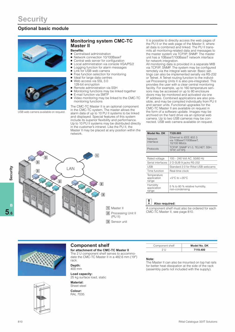
The CMC-TC Master II is an optional component in the CMC-TC system. The master allows the alarm data of up to 10 PU II systems to be linked and displayed. Special features of this system include its superior flexibility and performance. Up to 10 PU II systems may be distributed directly in the customer’s intranet. Like the PU II, the Master II may be placed at any position within the network.
It is possible to directly access the web pages of the PU II or the web page of the Master II, where all data is combined and linked. The PU II trans-mits all monitoring-related data and messages to the master system via TCP/IP, SNMP. The master unit has a 10BaseT/100BaseT network interface for network integration. All monitoring data is provided in a separate MIB via TCP/IP, SNMP. The system may be configured remotely via the integral web server. Basic set-tings can also be implemented serially via RS-232 or Telnet. A Telnet routing function to the individ-ual Processing Units II is also pre-integrated. This provides the user with a clear central monitoring facility. For example, up to 160 temperature sen-sors may be accessed or up to 80 enclosure doors may be monitored and activated via one IP address. Combined applications are also pos-sible, and may be compiled individually from PU II and sensor units. Functional upgrades for the CMC-TC Master II are available on request in the form of a software update. Images may be archived on the hard drive via an optional web camera. Up to two USB cameras may be con-nected. USB web camera available on request.
Also required:
A component shelf must also be ordered for each CMC-TC Master II, see page 810.
LAN
1
2
2
3
3
2
3
Master II
Processing Unit II (PU II)
Sensor unit
1
2
3
Model No. DK 7320.005
Network interface
Ethernet to IEEE 802.3 via 10BaseT/100BaseT, 10/100 Mbit/s
ProtocolsTCP/IP, SNMP V1.0, TELNET, SSH, TFTP, HTTPS
Rated voltage 100 – 240 Volt AC, 50/60 Hz
Serial interfaces 2 D-SUB 9 jacks RS-232
USB Standard 2.0 for Rittal USB webcams
Time function Real-time clock
Temperature application range
+5°C to +35°C
Humidity application range
5 % to 80 % relative humidity, non-condensing
USB web camera available on request.
Component shelf for attachment of the CMC-TC Master II The 2 U component shelf serves to accommo-date the CMC-TC Master II in a 482.6 mm (19″) rack.
Depth: 400 mm
Load capacity: 25 kg surface load, static
Material:Sheet steel
Colour:RAL 7035
Note:The Master II can also be mounted on top hat rails for better heat dissipation at the side of the rack (assembly parts not included with the supply).
Component shelf Model No. DK
2 U 7119.400

Sensor units
Security
811Rittal Catalogue 32/IT Solutions
B
5.6
Se
cu
rity
CMC-TC sensor units Description
I/O unit: The alarm and measurement module
Access unit: For controlling door systems
Climate unit: For fan control and monitoring
Fan Control System FCS:For DC fan
Benefits: ● Choice of functions thanks to twelve sensor
units ● Open to customer-specific sensors/actuators● Automatic sensor detection● Simple plug & play installation● No additional power pack required● Choice of mounting on the enclosure frame or
482.6 mm (19″) mounting angles● I/O unit: Freely selectable sensors/actuators● Access unit: Personalised access detection● Climate unit: Fan control with airflow monitoring
Interface for the sensor unit and processing unit connection. Used for data communication and power supply. Cable DK 7320.470
Just one press of the button, and the system automatically reconfigures itself.
Up to 3 systems may be integrated into the 1 U mounting unit DK 7320.440
Technical specifications:The sensors/actuators are set up via an auto-matic electronic ID system. Because it is installed using a flexible plug & play system, there is no need for time-consuming programming and wiring. Power is supplied centrally via the con-nection cable to the PU II.
Technical specifications:W x H x D: 136 mm x 44 mm (1 U) x 129 mm Temperature application range: +5°C to +45°C Humidity application range: 5 % to 95 % relative humidity, non-condensing
Protection category:IP 40 to EN 60 529/09.2000
Also required:
Connection cable DK 7320.470,see page 819.
1
2
3
1
2
3
I/O unit This allows alarm messages, status messages and measurements to be forwarded or remote actions to be executed via relay output modules. The I/O unit has 4 universal inputs/outputs. The sensors/actuators listed below can be operated here. The interface to the user network is via the PU II (processing unit), which is always required to operate the system.
Control key for detection/set-up of the sensors/actuators
Alarm LED signals alarms or configuration changes
Mounting fixture for DK 7320.440 or DK 7320.450
RJ 12, 4 inputs for sensors/actuators(see table)
RJ 45, connection to PU II DK 7320.100 via connection cable DK 7320.470 (The unit is also supplied with power via this connection.)
Note:For selection aid, see page 817.
CCMC-TC
I/O Unit
1 2 3
1
2
3
4 5
1 2 3 4
I/O
4
5
I/O unit Model No. DK
4 universal inputs or outputs 7320.210
Also required:
Sensors/actuators Max.Model No.
DKPage
Temperature sensor 4 7320.500 823
Humidity sensor 4 7320.510 823
Analog sensor input module “4 – 20 mA”
4 7320.520 825
Access sensor1) 4 x 5 7320.530 828
Vandalism sensor 4 7320.540 828
Acoustic sensor 4 7320.640 824
Airflow monitor 4 7320.550 823
Smoke alarm 4 7320.560 824
Motion sensor 4 7320.570 828
Digital input module 4 7320.580 825
Digital relay output module
4 7320.590 825
Voltage monitor 4 7320.600 826
Voltage monitor with 10 A switch output
2 – 4 7320.610 826
Voltage monitor with 16 A switch output
2 – 4 7320.611 827
48 V voltage monitor 4 7320.620 827
Leak sensor 4 7320.630 823
Leak sensor, 15 m 4 7320.631 824
Connection cable 7320.470 819
1) Up to a maximum of 5 sensors may be connected in series.

SecuritySensor units
812 Rittal Catalogue 32/IT Solutions
B
5.6
Se
cu
rity
Access unitWith this sensor unit, one or two doors may be released for access via the network, or per-sonalised opening via a read system (e. g. smart-card reader) may be initiated. The system also monitors the status of the door, handle or latch. Authorised access codes can be set up via HTTP. The sensors/actuators/readers listed below can be operated here. In order to operate the unit, at least one access sensor and at least one latch (e. g. handle) per door system must always be used.
Control key for detection/set-up of the sensors/actuators
Alarm LED signals alarms or configuration changes
Mounting fixture for DK 7320.440 or DK 7320.450
Inputs for access sensor, handles Latch system 1 (see table)
Inputs for access sensor, handles Latch system 2 (see table)
I2C bus for reader units Door system 1 and 2 (see table)
RJ 45 connection to PU II DK 7320.100 via connection cable DK 7320.470 (The unit is also supplied with power via this connection.)
Note:For selection aid, see page 817.
1 2 3
CCMC-TC
Access Unit
1
2
3
4
1
5 6 7
2
4
5
6
7
Access unit Model No. DK
Control of 2 door systems 7320.220
Also required:
Sensors/actuators Max.Model No.
DKPage
Access sensor1) 2 x 5 7320.530 828
Digital input module for door release
2 7320.580 825
Latch/reader
Ergoform-S handle FR/PS/TC/TE
2 7320.700 953
Electromagnetic Ergoform-S QR
2 on request 830
Comfort handle TS 8 with master key function
2 7320.721 829
TS 8 transponder handle with Legic unit
2 7320.781 832
Universal lock unit 2 7320.730 831
Digital relay output module for room door
2 7320.740 825
Universal handle 2 7320.950 830
Smartcard reader for door release
2 7320.750 833
Magnetic card reader for door release
2 7320.760 833
Coded lock for door release
2 7320.770 833
Connection cable 7320.470 819
1) Up to a maximum of 5 sensors may be connected in series.
Climate unitA temperature control circuit is installed with this sensor unit. Temperature setpoints are set via the PU II, and these are compared with the actual temperature. Depending on the result, the fan system is activated. Additional functions of the fans can also be monitored with an airflow sensor. Monitoring is only active whilst the fan is opera-tional. Other sensors may optionally be con-nected to the unit. In order to operate the unit as a temperature fan control circuit, at least one temperature sensor must always be used.
Control key for detection/set-up of the sensors/actuators
Alarm LED signals alarms or configuration changes
Mounting fixture for DK 7320.440 or DK 7320.450
Input for fan supply 115/230 V AC, cable 7200.210 – .215
Output to fan with cable DK 7200.215
RJ 12, 2 inputs for sensors (see table)
RJ 45 connection to PU II DK 7320.100 via connection cable DK 7320.470 (The unit is also supplied with power via this connection.)
Note:For selection aid, see page 817.
1 2 3
CCMC-TC
Climate Unit
1
2
3
4 5 6 7
4
5
6
7
Climate unit Model No. DK
Control of a fan system 7320.230
Also required:
Sensors Max.Model No.
DKPage
Temperature sensor 2 7320.500 823
Access sensor1) 2 x 5 7320.530 828
Airflow monitor 2 7320.550 823
Smoke alarm 2 7320.560 824
Motion sensor 2 7320.570 828
Digital input module 2 7320.580 825
Voltage monitor 2 7320.600 826
48 V voltage monitor 2 7320.620 827
Connection cable7320.470,7200.210
819
1) Up to a maximum of 5 sensors may be connected in series.

Sensor units
Security
813Rittal Catalogue 32/IT Solutions
B
5.6
Se
cu
rity
Fan Control System FCSSpeed-controlled fan system The Fan Control System regulates and controls the speed of up to 6 fans DK 7320.812, 24 V DC. This helps to save energy and reduce the noise level of the fans, as well as extending the service life. The failure of one or more fans is detected and notified in the form of a collective fault signal via LED display, beeper and integral alarm relay (floating change-over contact). Control is temperature-based using an external temperature sensor DK 7320.500. The tempera-ture setpoint is set via a switch on the front. The system may also optionally be set and monitored via the network (Web/SNMP). It is connected directly to the CMC-TC – Processing Unit II – DK 7320.100.
Functions: ● Speed-regulated speed control ● Fan speed monitoring ● Optional connection via Web/SNMP ● Redundant fan control; the air throughput of all
fans is automatically increased in the event of a system failure
● Plug & play installation via RJ 12 connector system
● 482.6 mm (19″) mounting is possible via DK 7320.440
Note:Supplied pre-configured on request: The FCS system may be fitted in all Rittal fan roofs. FCS fitted in fan roof, see page 704.
Supply with 24 V DC via
– Supply connection cable, direct DK 7320.813
– CMC-24 V power pack 100 – 230 V AC (input) DK 7320.425
– CMC-24 V power pack 48 V DC (input) DK 7320.435
RJ 45 jack for connecting to Processing Unit II DK 7320.100 (optional) (Cat 5 cable)
CMC-TC temperature sensor DK 7320.500
Alarm relay output 24/48 V DC, 1 A (floating change-over contact)
Fan with speed monitoring DK 7320.812 (24V DC)
2
3
4
5
1
24 V DC
FCSTo fit
Processing Unit IIModel No. DK
Without fan n 7320.810
1
2
3
4
5
Speed monitored/controlled fan systemBenefits: ● Excellent air throughput at a high operating
ratio ● Monitoring of fan speed ● Plug & play compatibility system ● Easily installed in Rittal fan roofs ● Long service life ● Noise minimisation/speed control ● Alarm message via the CMC-TC in the network
optionally possible ● Open power supply system 24/48 V DC/
100 – 230 V AC ● EMC compatibility via DC fan systems
Equipment
PropertiesModel No. FCS
DK 7320.810
Fan speed monitoring n
Pre-selectable speed n
Non-temperature dependent speed
n
Speed increase in the event of a fan failure
n
Collective fault signal n
Floating change-over contact n
LAN connection via PU II n
Configurable via LAN n
Alarm outputBeeper, LED, relay,
RJ 45 output for PU II
FCS sample order list: Control system with fan control and monitoring of 6 fans
Description Packs ofModel No.
DKPage
Fan Control System FCS 1 7320.810 813
CMC-TC power pack 24 V, input 100 – 230 V AC 1 7320.425 818
CMC-TC temperature sensor 1 7320.500 823
Fan 24 V DC (packs of 2) with speed monitoring 3 7320.812 814
RJ 12 extension for DC fan, 1 m (packs of 2) 3 7320.814 819
CMC connection cable D 230 V AC 1 7200.210 818
SecuritySensor units
814 Rittal Catalogue 32/IT Solutions
B
5.6
Se
cu
rity
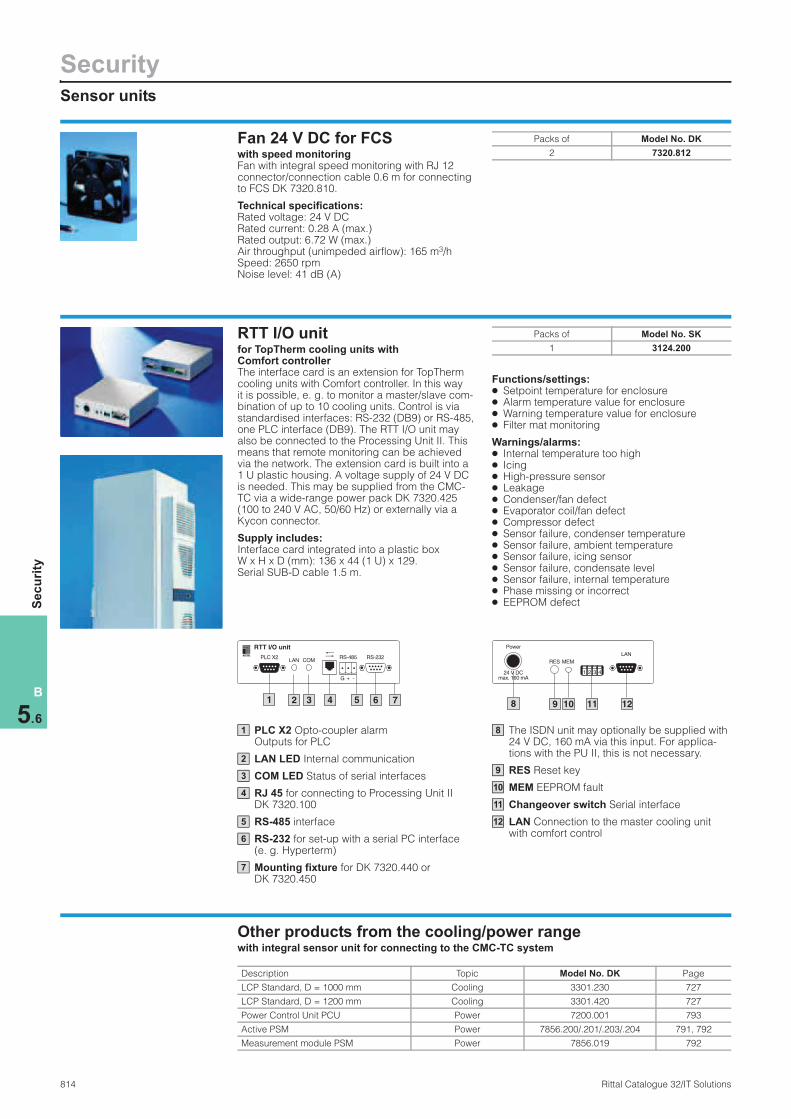
Fan 24 V DC for FCSwith speed monitoring Fan with integral speed monitoring with RJ 12 connector/connection cable 0.6 m for connecting to FCS DK 7320.810.
Technical specifications:Rated voltage: 24 V DC Rated current: 0.28 A (max.) Rated output: 6.72 W (max.) Air throughput (unimpeded airflow): 165 m3/h Speed: 2650 rpm Noise level: 41 dB (A)
Packs of Model No. DK
2 7320.812
RTT I/O unitfor TopTherm cooling units with Comfort controller The interface card is an extension for TopTherm cooling units with Comfort controller. In this way it is possible, e. g. to monitor a master/slave com-bination of up to 10 cooling units. Control is via standardised interfaces: RS-232 (DB9) or RS-485, one PLC interface (DB9). The RTT I/O unit may also be connected to the Processing Unit II. This means that remote monitoring can be achieved via the network. The extension card is built into a 1 U plastic housing. A voltage supply of 24 V DC is needed. This may be supplied from the CMC-TC via a wide-range power pack DK 7320.425 (100 to 240 V AC, 50/60 Hz) or externally via a Kycon connector.
Supply includes:Interface card integrated into a plastic box W x H x D (mm): 136 x 44 (1 U) x 129. Serial SUB-D cable 1.5 m.
Functions/settings: ● Setpoint temperature for enclosure ● Alarm temperature value for enclosure ● Warning temperature value for enclosure ● Filter mat monitoring
Warnings/alarms: ● Internal temperature too high ● Icing ● High-pressure sensor ● Leakage ● Condenser/fan defect ● Evaporator coil/fan defect ● Compressor defect ● Sensor failure, condenser temperature ● Sensor failure, ambient temperature ● Sensor failure, icing sensor ● Sensor failure, condensate level ● Sensor failure, internal temperature ● Phase missing or incorrect ● EEPROM defect
Packs of Model No. SK
1 3124.200
PLC X2 Opto-coupler alarm Outputs for PLC
LAN LED Internal communication
COM LED Status of serial interfaces
RJ 45 for connecting to Processing Unit II DK 7320.100
RS-485 interface
RS-232 for set-up with a serial PC interface (e. g. Hyperterm)
Mounting fixture for DK 7320.440 or DK 7320.450
1 2 3 4 5 6 7
RTT I/O unit
PLC X2
G + -
RS-485LAN COM
RS-232
1
2
3
4
5
6
7
The ISDN unit may optionally be supplied with 24 V DC, 160 mA via this input. For applica-tions with the PU II, this is not necessary.
RES Reset key
MEM EEPROM fault
Changeover switch Serial interface
LAN Connection to the master cooling unit with comfort control
8 9 10 1211
Power
1 2 3 424 V DCmax. 160 mA
RES MEM
LAN
8
9
10
11
12
Other products from the cooling/power range with integral sensor unit for connecting to the CMC-TC system
Description Topic Model No. DK Page
LCP Standard, D = 1000 mm Cooling 3301.230 727
LCP Standard, D = 1200 mm Cooling 3301.420 727
Power Control Unit PCU Power 7200.001 793
Active PSM Power 7856.200/.201/.203/.204 791, 792
Measurement module PSM Power 7856.019 792

Accessory modules
Security
815Rittal Catalogue 32/IT Solutions
B
5.6
Se
cu
rity
LCD display lights up (122 x 32 pixels)
“Change” for selection
“Enter” to confirm
“Clear” to delete/acknowledge
RJ 12 jack for connecting to the serial interface of the PU II
The GSM unit may optionally be supplied with 24 V DC, 150 mA via this input. For applica-tions with the PU II, this is not necessary.
1 4
CMC-TC
2 3
C
Display Unit II
1
2
3
4
5 6
Power
24 V DCmax. 2 A
5
6
Display Unit II The new Display Unit II may be linked directly to the PU II (DK 7320.100). CMC alarms, status messages, temperatures, voltages, currents etc. may be displayed on the screen, depending on the monitoring application. Additionally, the TCP/IP network settings of the PU II may be made using the three keys. The new LCD graphics module (122 x 32 pixels) is very easy to read, with good contrast and a modern design. The display is blue and white. It is illuminated via an LED. It is mounted in the 1 U component support DK 7320.440 or with the individual mounting unit DK 7320.450. Power supply is via the processing unit PU II. Power supply and data communication to the PU II is via the supplied patch cable.
Technical specifications: ● Plug & play installation via RJ 12 connector ● 122 x 32 pixel graphical display ● Colours blue and white ● LED lights up
Supply includes:Display module, cable for connecting to the PU II.
Note:The serial interface RS-232 of the PU II may only be assigned to one accessory module.
Packs of Model No. DK
1 7320.491
Also required:
Component Model No. DK
Processing Unit II 7320.100
ISDN unitIn order to configure a redundant transmission channel or if there is no network infrastructure available, the unit may be used for alarm forward-ing. The alarm signal is designed in SMS format. The ISDN unit is linked to the Processing Unit II DK 7320.100 via a serial interface. The power supply is likewise achieved via the connection cable. An ISDN connection is required in order to operate the module (see the requirements for an ISDN connection). Up to four target call numbers may be set and allocated to the various events. This variant of alarm reporting may also be used in countries with “SMS in the fixed network”. Furthermore, with “SMS in the fixed network”, it is also possible to control switch outputs via an SMS. Power is supplied via the Processing Unit II. CMC data may also be retrieved via the Web, Telnet or SNMP with the PPP protocol. In such cases, the SMS function cannot be used.
Other functions, where offered by the provider:
● Voice mail
Alarm LED
Status ISDN-LED
Mounting fixture for DK 7320.440 or DK 7320.450
RJ 45 ISDN jack
RJ 12 jack for connecting to the serial interface of the PU II
The ISDN unit may optionally be supplied with 24 V DC, 80 mA via this input. For applica-tions with the PU II, this is not necessary.
Requirements for the ISDN connection: ● DSS1 (Euro-ISDN) must also be provided when
connecting to the ISDN system ● Point-to-multi-point configuration
Note:The serial interface RS-232 of the PU II may only be assigned to one accessory module.
1 3
CMC-TCISDN UNITISDN
2
1
2
3
5 64
PowerIOIOIISDN
24 V DCmax. 80 mA
4
5
6
Components Model No. DK
ISDN unit 7320.830
Also required:
Components Model No. DK
Processing Unit II 7320.100
SecurityAccessory modules
816 Rittal Catalogue 32/IT Solutions
B
5.6
Se
cu
rity
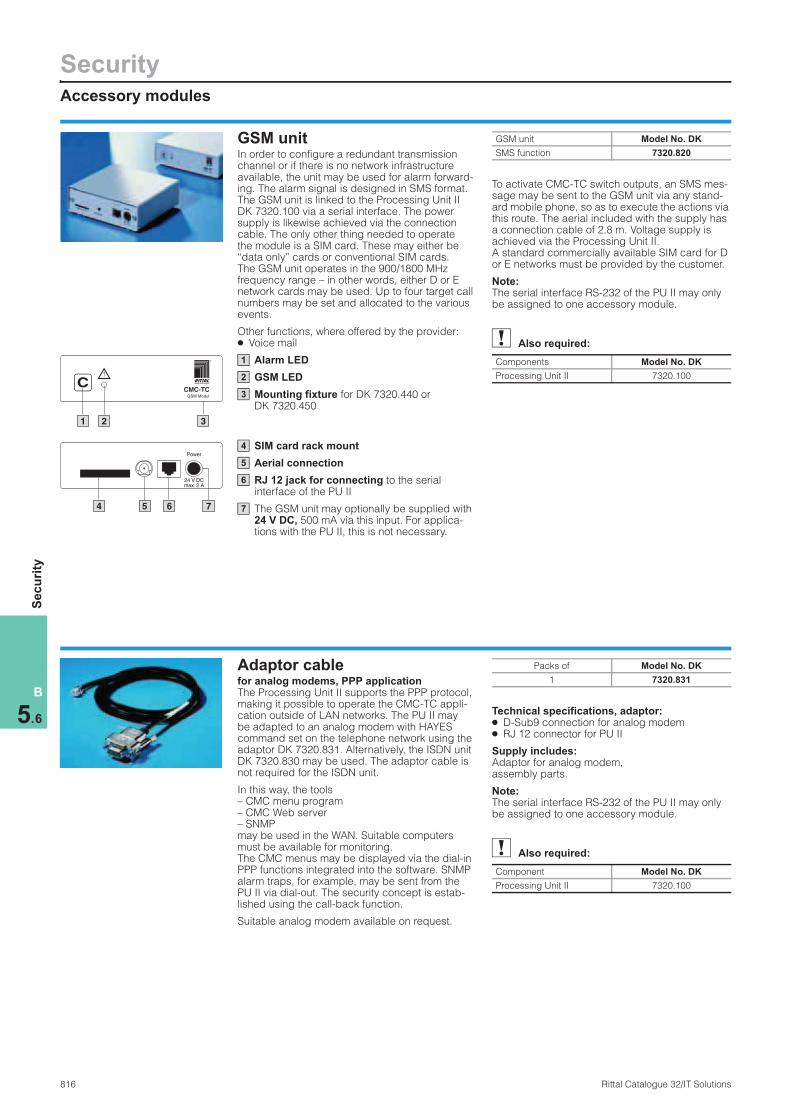
GSM unit In order to configure a redundant transmission channel or if there is no network infrastructure available, the unit may be used for alarm forward-ing. The alarm signal is designed in SMS format. The GSM unit is linked to the Processing Unit II DK 7320.100 via a serial interface. The power supply is likewise achieved via the connection cable. The only other thing needed to operate the module is a SIM card. These may either be “data only” cards or conventional SIM cards. The GSM unit operates in the 900/1800 MHz frequency range – in other words, either D or E network cards may be used. Up to four target call numbers may be set and allocated to the various events.
Other functions, where offered by the provider: ● Voice mail
Alarm LED
GSM LED
Mounting fixture for DK 7320.440 or DK 7320.450
SIM card rack mount
Aerial connection
RJ 12 jack for connecting to the serial interface of the PU II
The GSM unit may optionally be supplied with 24 V DC, 500 mA via this input. For applica-tions with the PU II, this is not necessary.
To activate CMC-TC switch outputs, an SMS mes-sage may be sent to the GSM unit via any stand-ard mobile phone, so as to execute the actions via this route. The aerial included with the supply has a connection cable of 2.8 m. Voltage supply is achieved via the Processing Unit II. A standard commercially available SIM card for D or E networks must be provided by the customer.
Note:The serial interface RS-232 of the PU II may only be assigned to one accessory module.
1 2 3
CCMC-TC
GSM Modul
1
2
3
4 5 6 7
Power
24 V DCmax. 2 A
4
5
6
7
GSM unit Model No. DK
SMS function 7320.820
Also required:
Components Model No. DK
Processing Unit II 7320.100
Adaptor cable for analog modems, PPP application The Processing Unit II supports the PPP protocol, making it possible to operate the CMC-TC appli-cation outside of LAN networks. The PU II may be adapted to an analog modem with HAYES command set on the telephone network using the adaptor DK 7320.831. Alternatively, the ISDN unit DK 7320.830 may be used. The adaptor cable is not required for the ISDN unit.
In this way, the tools – CMC menu program – CMC Web server – SNMP may be used in the WAN. Suitable computers must be available for monitoring. The CMC menus may be displayed via the dial-in PPP functions integrated into the software. SNMP alarm traps, for example, may be sent from the PU II via dial-out. The security concept is estab-lished using the call-back function.
Suitable analog modem available on request.
Technical specifications, adaptor: ● D-Sub9 connection for analog modem ● RJ 12 connector for PU II
Supply includes:Adaptor for analog modem, assembly parts.
Note:The serial interface RS-232 of the PU II may only be assigned to one accessory module.
Packs of Model No. DK
1 7320.831
Also required:
Component Model No. DK
Processing Unit II 7320.100
Connection/mounting accessories
Security
817Rittal Catalogue 32/IT Solutions
B
5.6
Se
cu
rity
Programming cable
Processing Unit II
Power pack
Connection cable for power pack
Connection cable for sensor units
Up to 4 sensor units
Examples The basic systemThe Processing Unit II (PU) forms the basis of any CMC-TC appli-cation. Connectivity is offered by the network interface (10/100BaseT, TCP/IP, SNMP, Web) directly into the user net-work or to the CMC-TC master. The following products are required for each CMC-TC application:
● Processing Unit II (DK 7320.100)
● Power pack 100 – 240 V 50 – 60 Hz (DK 7320.425) or power pack 48 V DC (DK 7320.435)
● Connection cable for power pack, country-specific (DK 7200.210 – .215)
● Connection cable for sensor unit (DK 7320.470)
● At least one sensor unit (DK 7320.210/.220/.230 etc.)
● Programming cable (DK 7200.221)
Example of a rack Functions: Temperature, humidity, smoke, access monitoring (doors/side panels)
Alarm routes: Via the network and GSM/SMS
Power supply: German network 230 V, 50 Hz.
Components Qty. Model No. DK
CMC-TC Processing Unit II 1 7320.100
CMC-TC I/O unit 1 7320.210
CMC-TC GSM unit 1 7320.820
CMC-TC power pack 24 V, input 100 – 230 V AC 1 7320.425
CMC-TC 1 U mounting unit 1 7320.440
CMC-TC connection cable, sensor unit, length 0.5 mm (packs of 4) 1 7320.470
CMC-TC temperature sensor 1 7320.500
CMC-TC humidity sensor 1 7320.510
CMC-TC smoke alarm 1 7320.560
CMC-TC access sensor (packs of 2) 4 7320.530
CMC-TC connection cable D 230 V AC 1 7200.210
CMC-TC programming cable 1 7200.221
Example of a TS 8 rack Functions: Fan with speed control, monitoring and access control remote + coded lock
Alarm routes: Via the network and Display Unit II
Power supply: US network 110 V, 60 Hz, redundant with A/B supply monitored.
Note:Fan mountings must be ordered according to the specific enclosure size.
Components Qty. Model No. DK
CMC-TC Processing Unit II 1 7320.100
CMC-TC I/O unit 1 7320.210
CMC-TC access unit 1 7320.220
CMC-TC Fan Control System FCS 1 7320.810
CMC-TC Display Unit II 1 7320.491
CMC-TC power pack 24 V, input 100 – 230 V AC 2 7320.425
CMC-TC redundant power supply 1 7320.426
CMC-TC second supply connection cable 24 V 1 7320.813
CMC-TC 1 U mounting unit 2 7320.440
CMC-TC connection cable, sensor unit, length 0.5 mm (packs of 4) 3 7320.470
CMC-TC temperature sensor 1 7320.500
CMC-TC access sensor (packs of 2) 4 7320.530
CMC-TC Comfort handle TS 8 with master key function 2 7320.721
CMC-TC coded lock 1 7320.770
CMC-TC fan 24 V DC with speed monitoring (packs of 2) 6 7320.812
CMC-TC RJ 12 extension for DC fan, 1 m (packs of 2) 6 7320.814
CMC-TC connection cable US 115 V, 60 Hz 2 7200.214
CMC-TC programming cable 1 7200.221

SecurityConnection/mounting accessories
818 Rittal Catalogue 32/IT Solutions
B
5.6
Se
cu
rity
Connection cable/extensionThe cable is used to connect to:● CMC-TC Master II● 24 V power pack for PU II ● Active fan unit for TE ● Climate unit (connected fan)● Voltage monitor● Voltage expansion unit
Technical specifications:PVC cable, 3 pole, with IEC connector (non-heat-ing appliances) with contact protection CEE22.
Supply includes:1 connection cable.
Country versionVoltage
VoltModel No.
DK
D / F / B 230 7200.210
GB 230 7200.2111)
CH 230 7200.2131)
USA / CDN 230/115 7200.2141)
IEC 320 extension 230/115 7200.215
1) Extended delivery times.
Connection/extension cable C19/C20The earthing pin/C19 connection cable DK 7200.216 is needed in order to supply power to the voltage monitor with 16 A C19/C20 switch output DK 7320.611. The C19/C20 extension cable DK 7200.217 is needed for the voltage monitor with 16 A C19/C20 switch output DK 7320.611 in order to connect a device.
Technical specifications:3-pole PVC cable with IEC cable coupling C19/C20/earthing-pin.
Supply includes:1 connection cable/extension cable.
Packs of Model No. DK
Connection cable D/C19
1 7200.216
Extension cableC19/C20
1 7200.217
Power pack for PU II, FCS A 24 V DC power pack is required to supply the Processing Unit II with power. There are two variants available:● The 100 – 240 V AC power pack requires an
IEC connection cable to supply the voltage● An alternative power pack is designed for
the telecommunications sector (48 V battery voltages) and is connected at the input end via a terminal block.
Both power packs include an output cable, 1.65 m long.
Technical specifications DK 7320.425:Rated voltage: 100 – 240 V AC, 50/60 Hz Rated current: Max. 1.5 A Secondary range: 24 V DC, 3 A
Technical specifications DK 7320.435:Rated voltage: 20 – 72 V DC Rated current: Max. 2.5 A Secondary range: 24 V DC, 1.3 A
Also required:
Connection cable for DK 7320.425 power pack, see page 818.
Primary input voltage
Output voltageModel No.
DK
100 – 240 V AC/ 50/60 Hz
24 V DC 7320.425
48 V DC 24 V DC 7320.435
Supply connection cablefor PU II/FCS If the customer is able to provide 24 V DC, the systems PU II/FCS may be supplied with power via the supply connection cable. No power packs are then required for the application. The cable is also used to extend the redundant power supply of the CMC-TC.
Packs of Length Model No. DK
1 2 m 7320.813

Connection/mounting accessories
Security
819Rittal Catalogue 32/IT Solutions
B
5.6
Se
cu
rity
Programming cableThe interface cable is used to configure the net-work parameters in the Processing Unit II and the Master Unit. The RJ 10 connector is connected to the front jack of the PU/master, whilst the 9-pole SUB-D connec-tor is connected to a serial PC interface.
Packs of Model No. DK
1 7200.221
Connection cable RJ 45 This cable is for data exchange and power supply to a sensor unit via the Processing Unit II. There is an RJ 45 connector at each end of the shielded cable. Additionally, the cables are used for appli-cations with the CMC-TC Master II, extension unit DK 7200.520 and SSC applications.
Length m Packs of Model No. DK
0.5 4 7320.470
2 4 7320.472
5 4 7320.475
10 1 7320.481
15 1 7320.485
Connection cable RJ 10, RJ 12 The RJ 12 connection cable allows the alarm relay output of the Processing Unit II to be used for indi-vidual alarm lights/indicators. The RJ 10 connec-tion cable facilitates connection to the CMC socket strip in conjunction with the digital input module. The cable is equipped with an RJ 10/12 connector at one end. The other end is open.
Connector Length m Packs of Model No. DK
RJ 10 5 4 7200.420
RJ 12 5 4 7200.430
Extension cable RJ 12 The cable is used to extend the sensor supply cables (RJ 12) and individual actuator cables. The cable is equipped with an RJ 10/12 connector at one end. There is an RJ 10/12 jack at the other end.
6 1
Example: RJ 12
Connector/jack Length m Packs of Model No. DK
RJ 12 5 4 7200.450
RJ 12 1 2 7320.814

SecurityConnection/mounting accessories
820 Rittal Catalogue 32/IT Solutions
B
5.6
Se
cu
rity
Redundant power supply The Y-adaptor supports a redundant design of the power supply to the CMC-TC system.
System supply inputs: The Y-adaptor has two 24 V DC inputs. This allows the connection of two 30 V AC power packs DK 7320.425 or two 48 V DC power packs DK 7320.435. The input therefore has a dual design. If one input fails, the second supply input will supply the required power. The system oper-ates without interruption.
Alarm display: There are two LEDs on the front of the device which display the status of the two supply inputs. At the rear there are two RJ 12 jacks which may be connected to the I/O unit DK 7320.210 of the CMC-TC system and indicate the status of the supply inputs.
System supply output:The system has one 24 V DC output which is accessed via terminals at the rear of the enclo-sure. The terminals may be connected to the power input of the PU II (DK 7320.100) and FCS (DK 7320.810) using the supply connection cable DK 7320.813. The terminals have a 3-way design, allowing the connection of up to 3 cables. A sup-ply connection cable is included with the supply.
Installation: May be mounted in the 1 U component support DK 7320.440 or with the individual mounting unit DK 7320.450.
Technical specifications, adaptor: ● Rated voltage 24 V DC ● Max. output current 3 A
Supply includes:Y-adaptor, 1 supply connection cable, two RJ 12 connection cables to the I/O unit.
Note:If several items of equipment are connected, a maximum of 3 A may be taken in total.
CCMC-TC
I/O-Unit
CCMC-TC
I/O-Unit
CCMC-TC
I/O-Unit
CCMC-TC
I/O-Unit
CCMC-TC
Processing Unit
1 2 3 4
IOIOI
CCMC-TC
Y-Adapter
Input 1 Input 2
11
2 2
3
6
7
5
8 8 8 8
4
U1 U2
24
V D
C23
0 V
AC
23
0 V
AC
24
V D
C
24
V D
C
Example:
Connection cable DK 7200.210
Power pack DK 7320.425
Redundant power supply DK 7320.426
Supply connection cable
Alarm outputs U1/U2
Processing Unit II DK 7320.100
Connection cable DK 7320.470
I/O unit DK 7320.210
1
2
3
4
5
6
7
8
Packs of Model No. DK
1 7320.426
Also required:
Description No. of packs Required Optional Model No. DK Page
AC power pack 230 V orDC power pack 48 V
2 2
n n
– –
7320.4251) 7320.435
818 818
Connection cable D/F/B orConnection cable GB or Connection cable CH or Connection cable USA/CDN or Connection cable C13
22222
n n n n n
– – – – –
7200.2101) 7200.2111) 7200.2131) 7200.2141) 7200.2151)
818 818 818 818 818
Supply connection cable (additional) 1 – 2 – n 7320.813 818
1 U mounting unit 1 – n 7320.440 821
Mounting module CMC 1 – n 7320.450 821
I/O unit 1 – n 7320.2102) 811
1) One connection cable is required for one power pack 2) A complete CMC-TC system is required to operate the I/O unit

Connection/mounting accessories
Security
821Rittal Catalogue 32/IT Solutions
B
5.6
Se
cu
rity
Mounting unit, 1 UThe mounting unit can accommodate up to 3 sensor units or Processing Units II and is used for accommodation in the 482.6 mm (19″) attach-ment level. Cable clamp straps DK 7610.000 or DK 7611.000 can be used for cable clamping.
Material:Sheet steel, spray-finished
Colour:RAL 7035
Accessories:
Cable clamp strap, see page 1070.
Packs of Model No. DK
1 7320.440
Single cover for 1 U mounting unit For CMC-TC applications the CMC-TC modules are attached to the 482.6 mm (19″) system of the enclosures via the 1 U mounting unit DK 7320.440. Up to 3 modules may be attached in one unit. Depending on the application, 1 or 2 installation openings will be left free. With a ventilated application, there is the risk of an air short-circuit. The free spaces may be covered with the single cover. The single cover consists of a film which is attached with adhesive and which may be removed again if necessary.
Supply includes:2 single covers
Packs of Model No. DK
2 7320.441
Mounting module CMCThe mounting module accommodates individual sensor units or processing units, for mounting on the frame section.
Material:Sheet steel, spray-finished
Colour:RAL 7035
Packs of Model No. DK
1 7320.450

SecurityConnection/mounting accessories
822 Rittal Catalogue 32/IT Solutions
B
5.6
Se
cu
rity
Fixture unit, 1 U for CMC-TC sensors The fixture unit offers the option of accommodat-ing up to 22 CMC-TC sensors. Depending on the design, there is a choice of 9 types (see table). This produces a patch front with 22 RJ 12 jacks. For sensors such as the digital input, the connec-tion to external systems may be made at the rear of the fixture unit. Incoming cables may still be clamped at the rear with cable ties. With this application, a height of 1 U is maintained. Alternatively, the fixture unit can also accommo-date up to 6 voltage monitors DK 7320.600. In this case, the installation height of 1 U is exceeded due to the large sensor height.
This provides CMC-TC sensors such as the digital input with a fixture unit in the 482.6 mm (19″) section of IT enclosures, ensuring professional accommodation of several sensors with neat cable clamping.
Supply includes:1 U fixture unit, trim panel.
Matching sensors/identification unit:
Packs of Model No. DK
1 7320.445
Description Max. (qty.)
Model No. DK
Temperature sensor 22 7320.500
Analog input 4 – 20 mA 22 7320.520
Vandalism sensor 22 7320.540
Digital input 22 7320.580
Relay output 22 7320.590
48 V voltage sensor DC 22 7320.620
Identification unit, universal lock 22 7320.730
Room door output module 22 7320.740
Voltage monitor 6 7320.600
Alarm signal lamp CMCThe alarm signal lamp serves as a collective fault signal for all alarms in the CMC-TC. For example: Temperature exceeded, fan defect, smoke alarm etc. The CMC-TC provides a user-friendly menu allowing the operator to select which message will affect the CMC-TC alarm relay. The alarm signal lamp is activated via the alarm relay. The lamp may be attached to the network enclo-sure or any other desired position, e. g. in the corridor. The RJ 12 connection cable is needed for con-necting to the PU II.
To fit Processing Unit II, see page 809.
Technical specifications:Rated operating voltage: 24 V DC Rated current: 60 mA
Also required:
Connection cable RJ 12 (DK 7200.430), see page 819.
Item Model No. SZ
LED steady light component 24 V DC, red
2372.000
Connection component 2368.010
Interference suppression capacitors for fans The capacitors are used for the interference suppression of fans with self-starting shaded pole motors. One capacitor should be connected directly parallel to the mains voltage for each fan unit. The capacitors are equipped with a terminal, which means that they are easily fitted to the fan cable.
Technical specifications:Dielectric strength: 275 V AC Capacity: 100 nF Type: X2
Design Packs of Model No. DK
100 nF 20 7200.490

Rack sensors
Security
823Rittal Catalogue 32/IT Solutions
B
5.6
Se
cu
rity
Temperature sensorThe sensor assumes the function of a tempera-ture monitor and contains an ID so that it is auto-matically detected and set up by the CMC-TC system. It is connected to a sensor unit via the connection cable supplied loose. The sensor can also control a fan on the climate unit or fan control system (FCS).
To fit sensor unit:
Technical specifications:Type: NTCResistance: 10 kOhm at 25°C Tolerance: ±2°C Connection: RJ 12 jack, 6-pole Connection cable: Length 2 m, RJ 12 connector 6/6 on both sides Temperature application range: +5°C to +45°C
Packs of Model No. DK
1 7320.500
I/O unit Access unit Climate unit FCS
n n n
Humidity sensorThe sensor measures relative air humidity and converts it into a frequency signal. It contains an ID so that it is automatically detected and set up by the CMC-TC system. Power supply and data evaluation is performed by the I/O sensor unit via the connection cable supplied loose.
To fit sensor unit:
Technical specifications:Sensor: With humidity/frequency converter (50 kHz at 76 % rel. hum.) Sensor measurement range: Relative humidity 10...90 % rel. humidity ±3 % (at 20°C) Connection: RJ 12 jack, 6-pole Connection cable: Length 2 m, RJ 12 connector 6/6 on both sides Temperature application range: +5°C to +45°C
Packs of Model No. DK
1 7320.510
I/O unit Access unit Climate unit
n
Leakage sensorThe leakage sensor is equipped with an optical sensor head. If this sensor head becomes wet, it reports a leakage alarm. The sensor head may be mounted facing the floor. If water collects there and comes into contact with the sensor head, the alarm is triggered. The sensor contains an ID so that it is automatically detected and set up by the CMC-TC system. The connection cable, supplied loose, should be used for connection to the sen-sor unit.
Protection category:IP 40
To fit sensor unit:
Technical specifications:Monitoring: Visual Connection: RJ 12 jack, 6-pole Connection cable: Length 2 m, RJ 12 connector 6/6 on both sides Temperature application range: +5°C to +45°C
Packs of Model No. DK
1 7320.630
I/O unit Access unit Climate unit
n
Airflow monitorThe airflow monitor determines whether the fan is achieving its full operating capacity. Storage damage, dirty filter mats or jammed fan blades are promptly detected and reported by the sensor. The sensor contains an ID so that it is automatically detected and set up by the CMC-TC system. Its switch point is adjustable.
Technical specifications:Connection: RJ 12 jack, 6-pole on the cable Connection cable: Length 2 m Temperature application range: +5°C to +45°C
To fit sensor unit:
Note:The sensor can be operated with temperature-controlled fan via the climate unit sensor unit.
Packs of Model No. DK
1 7320.550
I/O unit Access unit Climate unit
n n

SecurityRack sensors
824 Rittal Catalogue 32/IT Solutions
B
5.6
Se
cu
rity
Smoke alarmThe smoke alarm is based on an opto-electronic smoke particle evaluation within a measurement chamber. The alarm contains an ID so that it is automatically detected and set up by the CMC-TC system. The power supply and alarm relay to the sensor unit occurs via the supplied connection cable.
To fit sensor unit:
Technical specifications:Alarm type: Combustion product alarm (smoke) Sensor/transmitter: Silicon PIN photodiode/ GaAs infr. LEDMeasurement frequency: Once every ten seconds Power consumption: Max. 61 mA Connection: RJ 12 jack, 6-pole Connection cable: Length 2 m, RJ 12 connector 6/6 on both sides Dimensions (alarm with base/plinth): D = 100 mm, H = 50 mm Temperature application range: +5°C to +45°C
Packs of Model No. DK
1 7320.560
I/O unit Access unit Climate unit
n n
CMC-TC acoustic anti-vandalism sensorThe CMC-TC acoustic sensor may be used in all situations where protection from vandalism is required. The sensor responds to loud mechani-cal noises such as those associated with a break-in. The sensitivity of the sensor is adjustable. The sensor contains an ID so that it is automati-cally detected and set up by the CMC-TC system.
To fit sensor unit:
Technical specifications: Sensor: MicrophoneFrequency range: 50 Hz – 10 kHz Noise level: 60 – 100 dB (A)Response time: 20 msPatch cable to I/O Unit: 2 mRated voltage: 24 V DC Temperature range: +5°C to +45°C
Model No. DK
Acoustic sensor 7320.640
Extended delivery times.
I/O unit Access unit Climate unit
n
CMC-TC leak sensor, 15 mThe leak sensor is able to detect electrically conductive fluids such as freshwater, salt water, glycol solutions etc. over a distance of 15 m. The sensor may be fitted underneath water pipelines, LCP applications, climate control applications in bayed enclosure suites etc., preferably on the floor. Attachment on or close to the floor allows the system to detect even tiny quantities of fluid. The sensor may be connected directly to the I/O unit using the patch cable supplied loose via plug & play. The sensor contains an ID so that it is automatically detected and set up by the CMC-TC system. The 15 m long sensor cable is connected to an enclosure with the evaluation electronics via a 3.5 m long connection cable. The enclosure must be correctly installed according to the IP protec-tion category, e. g. in a Rittal rack. The sensor cable is colour-coded to distinguish it from other cables in the monitoring area. The carrier material PEHD is chemically neutral with long-term stability. The PHLD sensor cable is very robust and protects the measurement wires inside from damage and accidental activation. The sensor cable is liquid-repelling and can therefore be quickly reused following a leak.
To fit sensor unit:
Technical specifications: Monitoring: Conductive sensor cableLength of sensor cable: 15 mConnection cable to electronics: 3.5 mPatch cable to I/O unit: 2 mRated voltage: 24 V DC Protection category of electronics with enclosure: IP 40 to EN 60 529/09.2000Temperature range: +5°C to +45°C
Model No. DK
Leak sensor 7320.631
Extended delivery times.
I/O unit Access unit Climate unit
n

Universal sensors/actuators
Security
825Rittal Catalogue 32/IT Solutions
B
5.6
Se
cu
rity
Analog sensor input moduleThe input module facilitates the connection of indi-vidual external analog sensors (4 – 20 mA) to the I/O sensor unit. As an adaptor, it performs the function of identification, so that an external sensor is automatically identified and set up by the CMC-TC system. Sensors with 4 – 20 mA signal output and 24 V DC operating voltage (max. 50 mA) may be connect-ed. The CMC-TC makes its internal power source available. It is connected to a sensor unit via the connection cable supplied loose.
To fit sensor unit:
Technical specifications:Analog input: 4 – 20 mA at 24 V DC Maximum current output of the module: 50 mA Sensors without GND may also be used. Connection: RJ 12 jack, 6-pole Connection cable: Length 2 m, RJ 12 connector 6/6 on both sides Sensor connection: Pull-off clamping strip, 3-pole
Packs of Model No. DK
1 7320.520
I/O unit Access unit Climate unit
n
Digital sensor input moduleThe input module facilitates the connection of indi-vidual external digital sensors to a sensor unit. As an adaptor, it performs the function of identifica-tion, so that an external sensor is automatically identified and set up by the CMC-TC system. External sensors or detectors must have a float-ing contact (normally closed or normally open). It is connected to a sensor unit via the connection cable supplied loose. In conjunction with the access unit, any given door release system (e. g. transponder) with a floating relay contact may be connected via the input module. The input can be used as either “Normally Open” or “Normally Closed”.
To fit sensor unit:
Technical specifications:Floating external sensor contact: Voltage min. 24 V DC load capacityCurrent: Min. 10 mA load capacity Connection: RJ 12 jack, 6-pole Connection cable: Length 2 m, RJ 12 connector 6/6 on both sides Sensor connection: Pull-off clamping strip, 3-pole
Packs of Model No. DK
1 7320.580
I/O unit Access unit Climate unit
n n n
Relay output moduleThe output module allows individual, external extra-low voltage actuators to be switched via a change-over contact. As an intermediate relay, it performs the function of identification and isola-tion, so that an actuator is automatically identified and set up by the CMC-TC system. It is connected to the I/O sensor unit via the con-nection cable supplied loose. At the output end, the module contains a pull-off terminal strip for assignment with actuator cables. Power supply to the actuator must be provided externally. The output relay may be switched remotely via SNMP or HTTP. Alternatively, alarm links can also be created with alarm inputs.
To fit sensor unit:
Technical specifications:Condition of the actuator: cosphi = 1Max. load of the switch contact: 1 A, 30 V DC and 0.5 A, 48 V AC Max. switching voltage: 48 V AC; 48 V DC Max. switched current: 1 A Max. switching load: 30 W, 62.5 VA Min. switched current: 1 mA at 5 V DC Connection: RJ 12 jack, 6-pole Connection cable: Length 2 m, RJ 12 connector 6/6 on both sides Sensor connection: Pull-off clamping strip, 3-pole
Packs of Model No. DK
1 7320.590
I/O unit Access unit Climate unit
n

SecurityPower sensors
826 Rittal Catalogue 32/IT Solutions
B
5.6
Se
cu
rity
Extension unit CMC-TCThree-phase voltageThe CMC-TC extension unit picks off three inde-pendently monitored mains voltages via network cables and forwards the measurements to the Processing Unit II. It is linked to the PU II via the RJ 45 connection cable on the P-I2C port (sep. accessory). Up to two extension units may be connected serially to one PU. A separate power pack is not required. Alarm limits may be preset for all voltages.
Technical specifications:Voltage inputs: 3 x 100 – 230 V AC, IEC connector Interface: P-I2C, max. cable length 2 m Temperature application range: +5°C to +45°C Tolerance: ±5 % at 20 – 30°C
Protection category:IP 40
Note:To fit Processing Unit II DK 7320.100, see page 809. For applications with SMS functions, voltage monitors must be used.
Also required:
3 x IEC connection cable DK 7200.210, see page 818.
Accessories:
RJ 45 connection cable, see page 819.
Max. number per PU II Packs of Model No. DK
2 1 7200.520
Voltage monitorThe voltage monitor picks up a mains voltage to be monitored via the mains cable, and reports its status to a sensor unit: Voltage ON or voltage OFF. The monitor contains an ID so that it is automati-cally detected and set up by the CMC-TC sys-tem. The connection cable, supplied loose, should be used for connection to the sensor unit.
Technical specifications:Monitored rated voltage: 230 V AC 50/60 Hz Connections: IEC connector, RJ 12 jack, 6-pole Connection cable: Length 2 m, RJ 12 connector 6/6 on both sides Temperature application range: +5°C to +45°C
To fit sensor unit:
Protection category:IP 40
Also required:
IEC connection cable DK 7200.210, see page 818.
Packs of Model No. DK
1 7320.600
I/O unit Access unit Climate unit
n n
Voltage monitor with 10 A IEC switch output This sensor is used in conjunction with the CMC-TC to monitor voltage limits. The limits may be set via the WEB interface or SNMP. As an additional option, this voltage may also be switched on and off via the module, in order to reboot connected equipment via Ethernet. It is connected via standard, commercially availa-ble IEC320 connectors as the input signal, and an IEC320 socket to connect the equipment.
Technical specifications: ● Plug & play compatibility system ● Initiation of the switching operation may be
manually or event-based via SNMP or WEB ● The min./max. limits of voltage measurement
are freely selectable● Measurement range 100 – 250 V AC, 50/60 Hz● Max. switching load 250 V AC and 10 A
at cosphi = 1● Tolerance: ±5 % at 20 – 30°C
To fit sensor unit:
Note:The system has two functions. Each function occupies one input of the I/O unit. 1st function: Voltage measurement 2nd function: Relay switching (at zero current, with normally open contact)
Also required:
IEC connection cable DK 7200.210, German version, IEC extension cable DK 7200.215 for connecting the equipment, see page 818.
Packs of Model No. DK
1 7320.610
I/O unit Access unit Climate unit
n

Power sensors
Security
827Rittal Catalogue 32/IT Solutions
B
5.6
Se
cu
rity
Voltage monitor with 16 A C19/C20 switched outputThis sensor is used in conjunction with the CMC-TC to monitor voltage limits. The limits may be set via the WEB interface or SNMP. As an additional option, this voltage may also be switched on and off via the module, in order to reboot connected equipment via Ethernet. It is connected via a C19 connector as the input signal, and a C20 socket to connect the equipment (connection cable/exten-sion cable DK 7200.216/.217).
Technical specifications: ● Plug & play installation ● Initiation of the switching operation may be
manually or event-based via SNMP or WEB ● The min./max. limits of voltage measurement
are freely selectable ● Voltage input 230 Volt ±10 %, 50/60 Hz ● Max. switching load 250 V AC and 16 A at
cos phi = 0 – 1 ● Tolerance: ±5 % at 20 – 30°C
To fit sensor unit:
Note:The system has two functions. Each function occupies one input of the I/O unit. 1st function: Voltage measurement 2nd function: Relay switching (at zero current, with normally closed contact) To fit sensor unit > I/O unit.
Packs of Model No. DK
1 7320.611
I/O unit Access unit Climate unit
n
Also required:
Components Model No. DK Page
Connection cable D/C19 7200.216 818
Extension cable C19/C20
7200.217 818
Voltage monitor 48 V DCThe voltage monitor picks off a mains voltage to be monitored via the 3-pole jack, and reports its status to a sensor unit: Voltage ON or voltage OFF. The monitor contains an ID so that it is automati-cally detected and set up by the CMC-TC sys-tem. The connection cable, supplied loose, should be used for connection to the sensor unit.
Technical specifications:Monitored rated voltage: 48 V DC (12 – 60 Volt DC/12 – 25 Volt AC 50/60 Hz)Connections: 3-pole connector, RJ 12 jack, 6-pole Connection cable: Length 2 m, RJ 12 connector 6/6 on both sides Temperature application range: +5°C to +45°C
To fit sensor unit:
Protection category:IP 40
Packs of Model No. DK
1 7320.620
I/O unit Access unit Climate unit
n n
Socket strip CMC-TCWith integral● Interference suppressor filter● Overvoltage protection● Alarm contact
In the event of interference caused by overvolt-age, the connected active network components are protected. With the relay message contact, undervoltage and any malfunctions caused by overvoltage can be reported via the CMC-TC in the network (SNMP trap). A green light on the strip indicates that the device is operational. The second protective device is the interference suppressor filter which protects valuable equip-ment as a passive component.
Technical specifications:Number of sockets: 9 Length of strip: 650 mmRated voltage: 230 V AC, 50/60 Hz Rated current: 16 A Relay alarm output: RJ 10 jack Relay load capacity: 50 Volt DC 100 mA
To fit sensor unit:
Technical specifications, overvoltage protection: Arrester application category: D Surge current resistance per conductor: 2.5 kA Maximum surge strength: 8 kA
Also required:
A digital input module DK 7320.580 and an RJ 10 connection cable DK 7200.420 is needed to link the CMC socket strip to the CMC-TC system.
Packs of Model No. DK
1 7200.630
I/O unit Access unit Climate unit
n n
SecurityAccess systems
828 Rittal Catalogue 32/IT Solutions
B
5.6
Se
cu
rity
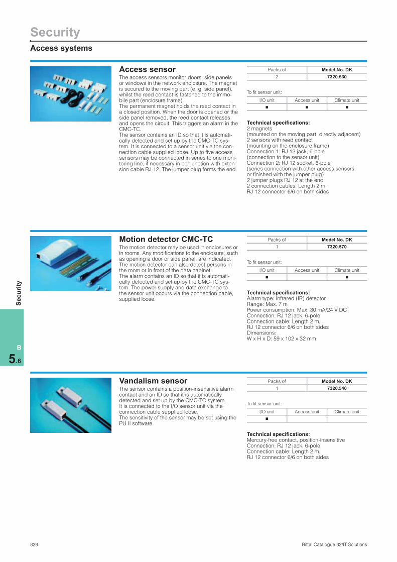
Access sensorThe access sensors monitor doors, side panels or windows in the network enclosure. The magnet is secured to the moving part (e. g. side panel), whilst the reed contact is fastened to the immo-bile part (enclosure frame). The permanent magnet holds the reed contact in a closed position. When the door is opened or the side panel removed, the reed contact releases and opens the circuit. This triggers an alarm in the CMC-TC. The sensor contains an ID so that it is automati-cally detected and set up by the CMC-TC sys-tem. It is connected to a sensor unit via the con-nection cable supplied loose. Up to five access sensors may be connected in series to one moni-toring line, if necessary in conjunction with exten-sion cable RJ 12. The jumper plug forms the end.
To fit sensor unit:
Technical specifications:2 magnets (mounted on the moving part, directly adjacent) 2 sensors with reed contact (mounting on the enclosure frame) Connection 1: RJ 12 jack, 6-pole (connection to the sensor unit) Connection 2: RJ 12 socket, 6-pole (series connection with other access sensors, or finished with the jumper plug)2 jumper plugs RJ 12 at the end 2 connection cables: Length 2 m, RJ 12 connector 6/6 on both sides
Packs of Model No. DK
2 7320.530
I/O unit Access unit Climate unit
n n n
Motion detector CMC-TCThe motion detector may be used in enclosures or in rooms. Any modifications to the enclosure, such as opening a door or side panel, are indicated. The motion detector can also detect persons in the room or in front of the data cabinet. The alarm contains an ID so that it is automati-cally detected and set up by the CMC-TC sys-tem. The power supply and data exchange to the sensor unit occurs via the connection cable, supplied loose.
To fit sensor unit:
Technical specifications:Alarm type: Infrared (IR) detectorRange: Max. 7 mPower consumption: Max. 30 mA/24 V DCConnection: RJ 12 jack, 6-pole Connection cable: Length 2 m, RJ 12 connector 6/6 on both sides Dimensions: W x H x D: 59 x 102 x 32 mm
Packs of Model No. DK
1 7320.570
I/O unit Access unit Climate unit
n n
Vandalism sensorThe sensor contains a position-insensitive alarm contact and an ID so that it is automatically detected and set up by the CMC-TC system. It is connected to the I/O sensor unit via the connection cable supplied loose. The sensitivity of the sensor may be set using the PU II software.
To fit sensor unit:
Technical specifications:Mercury-free contact, position-insensitiveConnection: RJ 12 jack, 6-pole Connection cable: Length 2 m, RJ 12 connector 6/6 on both sides
Packs of Model No. DK
1 7320.540
I/O unit Access unit Climate unit
n

Access systems
Security
829Rittal Catalogue 32/IT Solutions
B
5.6
Se
cu
rity
Room door output moduleThe room door output module allows external door opener systems to be switched via a change-over contact. As an intermediate relay, it performs the function of identification and isolation, so that a door opener is automatically identified and set up by the CMC-TC system. It is connected to the access unit via the con-nection cable supplied loose. At the output end, the module contains a pull-off terminal strip for assignment with actuator cables. Power supply to the door opener must be provided externally.
To fit sensor unit:
Technical specifications:Condition of the actuator: cosphi = 1Max. load of the switch contact: 1 A, 30 V DC and 0.5 A, 48 V AC Max. switching voltage: 48 V AC; 48 V DC Max. switched current: 1 A Max. switching load: 30 W, 62.5 VA Min. switched current: 1 mA at 5 V DC Connection: RJ 12 jack, 6-pole Connection cable: Length 2 m, RJ 12 connector 6/6 on both sides Sensor connection: Pull-off clamping strip, 3-pole
Note:One access sensor DK 7320.530 is always needed for each output module.
Packs of Model No. DK
1 7320.740
I/O unit Access unit Climate unit
n
Comfort handle TS 8 with master key function The handle assumes the function of a door lock and lever handle monitoring. Master key means that the handle can always be opened with the master key, independently of the control system. A semi-cylinder (security lock 3524 E) is supplied loose, but a semi-cylinder 40 mm overall length to DIN 18 254 may also be used. An access sensor (DK 7320.530) must be connected to the corresponding door for each handle. If the lever handle is closed, the locking mecha-nism integrated into the handle latches auto-matically. The handle may be released via the CMC-TC system in the network or via optional add-on systems, such as smartcard readers etc. The handle is locked in a de-energised manner (without electrical connection). The push-button may be depressed following electrical release and then opens the lever automatically. Opening via the key is always superordinate, i. e. the enclosure may always be opened with the key in the case of electrical locking and in the event of a power failure (emergency opening).
To fit sensor unit:
Technical specifications:Rated voltage: 24 V DC Rated current: Max. 100 mAConnection cable: Length 3 m, RJ 12 connectorConnection cable: Length 2 m, RJ 12/RJ 12 connectorCoupling for extension: RJ 12/RJ 12 jackTemperature application range: +5°C to +40°C
Protection category:IP 40
Also required:
Access sensor DK 7320.530,see page 828.
Handle system Model No. DK
Comfort handle TS 8 with master key function
7320.721
I/O unit Access unit Climate unit
n
SecurityAccess systems
830 Rittal Catalogue 32/IT Solutions
B
5.6
Se
cu
rity
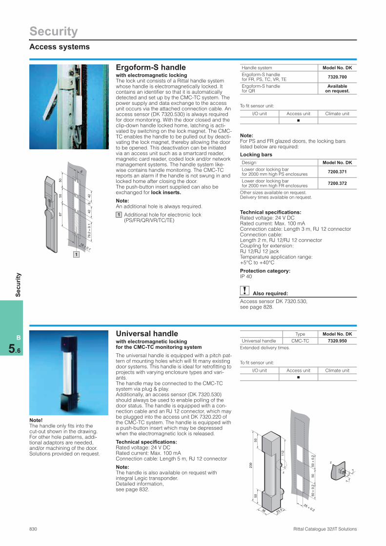
Ergoform-S handlewith electromagnetic locking The lock unit consists of a Rittal handle system whose handle is electromagnetically locked. It contains an identifier so that it is automatically detected and set up by the CMC-TC system. The power supply and data exchange to the access unit occurs via the attached connection cable. An access sensor (DK 7320.530) is always required for door monitoring. With the door closed and the clip-down handle locked home, latching is acti-vated by switching on the lock magnet. The CMC-TC enables the handle to be pulled out by deacti-vating the lock magnet, thereby allowing the door to be opened. This deactivation can be initiated via an access unit such as a smartcard reader, magnetic card reader, coded lock and/or network management systems. The handle system like-wise contains handle monitoring. The CMC-TC reports an alarm if the handle is not swung in and locked home after closing the door. The push-button insert supplied can also be exchanged for lock inserts.
Note:An additional hole is always required.
Additional hole for electronic lock (PS/FR/QR/VR/TC/TE)
To fit sensor unit:
Note:For PS and FR glazed doors, the locking bars listed below are required:
Locking bars
Technical specifications:Rated voltage: 24 V DC Rated current: Max. 100 mAConnection cable: Length 3 m, RJ 12 connectorConnection cable: Length 2 m, RJ 12/RJ 12 connectorCoupling for extension: RJ 12/RJ 12 jackTemperature application range: +5°C to +40°C
Protection category:IP 40
Also required:
Access sensor DK 7320.530,see page 828.
42
42
79.2
+ 0
.1
50
50
87
8
18 ± 0.1
6
1
1
Handle system Model No. DK
Ergoform-S handle for FR, PS, TC, VR, TE
7320.700
Ergoform-S handle for QR
Available on request.
I/O unit Access unit Climate unit
n
Design Model No. DK
Lower door locking bar for 2000 mm high PS enclosures
7200.371
Lower door locking bar for 2000 mm high FR enclosures
7200.372
Other sizes available on request. Delivery times available on request.
Universal handlewith electromagnetic lockingfor the CMC-TC monitoring system
The universal handle is equipped with a pitch pat-tern of mounting holes which will fit many existing door systems. This handle is ideal for retrofitting to projects with varying enclosure types and vari-ants. The handle may be connected to the CMC-TC system via plug & play. Additionally, an access sensor (DK 7320.530) should always be used to enable polling of the door status. The handle is equipped with a con-nection cable and an RJ 12 connector, which may be plugged into the access unit DK 7320.220 of the CMC-TC system. The handle is equipped with a push-button insert which may be depressed when the electromagnetic lock is released.
Technical specifications:Rated voltage: 24 V DC Rated current: Max. 100 mAConnection cable: Length 5 m, RJ 12 connector
Note:The handle is also available on request with integral Legic transponder. Detailed information, see page 832.
To fit sensor unit:
33.5
50
50
239
36
50 +
0.2
50
50 +
0.2
25 + 0.2
112
z
z
7
7
Note! The handle only fits into the cut-out shown in the drawing. For other hole patterns, addi-tional adaptors are needed, and/or machining of the door. Solutions provided on request.
Type Model No. DK
Universal handle CMC-TC 7320.950
Extended delivery times.
I/O unit Access unit Climate unit
n

Access systems
Security
831Rittal Catalogue 32/IT Solutions
B
5.6
Se
cu
rity
Transponder handle TS 8with integral transponder release system from Simons & Voss.
The electromagnetic transponder handle TS 8 may be retrofitted in the doors of TS 8/FR(i) enclosures. The handle is equipped with an inte-gral radio transponder solution. The transponder receiver with battery is integrated into the handle housing. Apart from the transponder transmitter, no additional accessories, such as additional electronics, cables, power pack etc., are required. The handle is easily exchanged without the need for wiring. If battery servicing is required, this is indicated acoustically. The handle is supplied in the zero state, so that it may be opened with any transponder transmitter.
Use with hand-held transmitter: The transponder transmitter is actuated from the handle, as a result of which the latter is unlatched for a specified time window and may be opened by pressing the push-button.
Use with the CMC-TC transmitter: The transponder transmitter is linked to the CMC-TC system via the room door output DK 7320.740 and the access unit. The transmitter is placed in the enclosure frame, near the handle. In this way, the door may be released via the CMC-TC system. Additionally, an access sensor (DK 7320.530) should always be used to enable polling of the door status.
Use of the programmable transponder: The programmable transponder allows the individual transponder transmitters to be allo-cated to individual handles. Matrix programming is supported.
Benefits: ● No cables on the handle, because the electron-
ics and battery are integrated into the handle.● Several users may be set for one handle.● Plug & play installation both mechanical and
electrical.● Individual control of the transponders and the
set-up of each transponder is possible for up to 3 locking systems.
● With additional overlay to automatically block the old transponder in the event of reprogram-ming.
● Counterfeit-proof data communication is achieved via radio using crypto-codes.
● The “challenge response procedure” ensures protection against surveillance.
● The standard interface means that connections to other access and monitoring systems are not a problem.
The lock and organisation sytem is graded in the highest category with respect to unlocking protection to BSI 7500.
Note:Systems with extra electronics and access control from Simons & Voss available on request.
Type Model No. DK
Electromagnetic handle
Transponder, stand-alone application
7320.960
Transponder transmitter
Hand-held transmitter
7320.961
Transponder transmitter
CMC-TC transmitter
7320.962
Programmable transponder
Programming 7320.963
Extended delivery times.
Universal lock unitThe security lock consists of a base unit and a lock counterpart. The base unit is attached to the enclosure frame. The lock counterpart is attached to the door. A mechanical setting allows you to choose between two states: At zero current when open, or at zero current when closed. In order to identify the operating mode used, one of the two identifier modules (supplied loose) should be used, so that it is automatically identi-fied and set up by the CMC-TC system. Power supply and data exchange is via the access unit, using the identifier modules and connection cables supplied loose. An access sensor (DK 7320.530) is always required for door monitoring.
Technical specifications:Rated voltage: 24 V DC Rated current: 140 mATemperature application range: +10°C to +40°C
Supply includes:1 base unit with connection cable 0.1 m, RJ 12 connector,1 lock counterpart,2 identifier modules with RJ 12 jack, 6-pole (connection to access unit), RJ 12 jack, 6-pole (connection to universal lock), 1 connection cable for identifier modules, 2 m, RJ 12/RJ 12 connector without mounting kit.
To fit sensor unit:
Note:Mounting kits depending on enclosure/door type available on request.
Also required:
Access sensor DK 7320.530,see page 828.
Packs of Model No. DK
1 set 7320.730
I/O unit Access unit Climate unit
n

SecurityAccess systems
832 Rittal Catalogue 32/IT Solutions
B
5.6
Se
cu
rity
Transponder comfort handle TS 8 with Legic Unit With the CMC-TC system, Rittal offers an access system for racks. One form of access control is the release of the enclosure doors with Legic transponder technology. The popular Legic sys-tem is often used for access control in buildings. With the transponder handles, Rittal offers the option of opening the enclosure doors via Legic transponder cards. In this way, doors in buildings and Rittal enclosure doors may be opened via a transponder card. The new TS 8 transponder handle has a similar design to the comfort handle TS 8 with master key function DK 7320.721. In the transponder handle, the master key function is replaced by the Legic system. The handle may be connected as usual to the access unit DK 7320.220 of the CMC system and activated.
Additional transponder function in the handle: Additionally, the handle contains a transponder receiver aerial, an LED and an acoustic signal generator. The functions are linked to the Legic unit B-Net 9106 – the control electronics for the transponder signals – via an integral connection cable.
Legic Unit B-Net 9106:The Legic unit is integrated into a CMC-TC enclo-sure and may be mounted in the 1 U component support DK 7320.440 or with the individual mount-ing unit DK 7320.450. In order to create a complete access system, the Legic unit must be connected to the serial interface of the PU II. Optionally this may also be connected to the P-I2C bus (input for reader units) of the corresponding access unit DK 7320.220.
Technical specifications:Rated voltage: 24 V DC Interface: RS-232/P-I2C Transmission system: Legic transponder Carrier frequency: 13.56 MHzProtection category: IP 40 Temperature range: +5°C to +40°C
Supply includes:– TS 8 handle with transponder antenna and
acoustic/optic display – Legic Unit B-Net 9106 with RS-232/P-I2C
interface – 3 transponder cards
Note:When using the handle, an access sensor DK 7320.530 must always be used. The serial interface RS-232 of the PU II may only be assigned to one accessory module/Legic Unit. In example 2 only the last 4 transponder digits are processed.
For the RS-232 application, the connection cable (PU II/Legic Unit) DK 7320.814 is required.
Application:
Example 1: Connection via the RS-232 der PU II 4 enclosures (front and rear) with one Legic reader:
Example 2: Connection via P-I2C of the access unit 4 enclosures (front and rear) with 8 Legic readers:
Transponder comfort handle TS 8
Packs ofModel No.
DK
Legic Unit B-Net 9106 1 7320.781
Extended delivery times.
Description Qty. Model No. DK
CMC-TC Processing Unit II 1 7320.100
CMC-TC access unit 4 7320.220
CMC-TC power pack 24 V, input 100 – 230 V AC
1 7320.425
CMC-TC 1 U mounting unit 2 7320.440
Cable clamp strap 2 7611.000
CMC-TC connection cable, sensor unit, 0.5 m long(packs of 4)
4 7320.470
CMC-TC access sensor (packs of 2)
8 7320.530
CMC-TC electromagnetic TS 8 handle with master key function
7 7320.721
Transponder comfort handle TS 8 with Legic Unit
1 7320.781
CMC connection cable D 230 V AC
1 7200.210
Programming cable 1 7200.221
Connection PU II/Legic Unit 1 7320.814
Description Qty. Model No. DK
CMC-TC Processing Unit II 1 7320.100
CMC-TC access unit 4 7320.220
CMC-TC power pack 24 V, input 100 – 230 V AC
1 7320.425
CMC-TC 1 U mounting unit 2 7320.440
Single mounting unit 8 7320.450
Cable clamp strap 2 7611.000
CMC-TC connection cable, sensor unit, 0.5 m long(packs of 4)
4 7320.470
CMC-TC access sensor (packs of 2)
8 7320.530
Transponder comfort handle TS 8 with Legic Unit
8 7320.781
CMC connection cable D 230 V AC
1 7200.210
Programming cable 1 7200.221

Access systems
Security
833Rittal Catalogue 32/IT Solutions
B
5.6
Se
cu
rity
Smartcard reader/Magnetic card reader/Coded lockThe door handle is released to authorised persons who have identified themselves with a smartcard/magnetic card/combination code. Smartcard readers/magnetic readers/coded locks are installed above the enclosure handle and can also function as a central unit for releasing sev-eral doors. The entire access procedure can also be regis-tered with the CMC-TC where there is network connection.
Technical specifications:Rated voltage: 24 V DC Rated current: Max. 20 mA Smartcard type: I2C chip Magnetic card type: Magnetic strip cards with data on track 2. The read system is designed for cards with both a high and a low level of magnetism.
To fit sensor unit:
Note:Smartcard readers/magnetic card readers/coded locks may only be used in conjunction with the CMC-TC and an electric lock. 3 cards are sup-plied with the smartcard reader/magnetic card reader. Each card contains a four-digit code, which is different on all three cards. All cards are access-authorised. The code may be input directly on the coded lock. Authorised codes may be set in the CMC-TC via Web. The input code is transmitted to the CMC-TC and, where applicable, to the network management system, via the I2C bus. A mounting adaptor for a TS aluminium glazed door is sup-plied loose with every reader.
25
190
50
120
166
83
8.5
4
35
190
50
120
166
83
8.5
4
25
190
50
120
166
83
8.5
4
Read system Model No. DK
Smartcard reader 7320.750
Magnetic card reader 7320.760
Coded lock 7320.770
I/O unit Access unit Climate unit
n
Mechanical lock systemscan be found under system accessories from page 947.

SecurityCMC-TC wireless sensor network
834 Rittal Catalogue 32/IT Solutions
B
5.6
Se
cu
rity
Flexible The use of radio sensors is appropriate whenever direct cabling between the sensor and I/O unit is too time-consuming or too diffi-cult to implement, e. g. for outdoor cabling, or in inaccessible places in the server rack or within the IT infrastructure of data centres (indoors). This eliminates the need for cabling, and the system is easily retrofitted while operational. There is no need to lay any cable trunking or modify the IT infrastructure. The position of the measur-ing point may also be altered retrospectively by simply moving the sensor. If the sensors are used in racks, the position of the enclo-sure may be flexibly modified with due regard for the radio connec-tion.By connecting the Wireless I/O Unit to the existing CMC-TC monitor-ing system, the system may be extended in a modular and flexible manner. In order to optimise radio links, an external aerial may optionally be used on the Wireless I/O Unit. Similarly, the transmis-sion and reception range may be flexibly extended using additional Wireless I/O Units as repeaters. The transmitter and receiver of the wireless network need not have visual connection, which likewise serves to increase flexibility.
Plug & play compatibility systemThe wireless sensor network is easily set up using plug & play installation. By means of a simple commissioning procedure comprised of a learning mode and learning key, the sensors are taught by the Wire-less I/O Unit via plug & play. Rittal offers a wireless measurement system with digital display for identifying the optimum radio connec-tion for the assembly site. This measurement system has the same design as the sensors and may be connected to the reference loca-tion of the sensor for test purposes.
Modular The wireless sensor network is comprised of a central Wireless I/O Unit, and the wireless sensors. One Wireless I/O Unit is capable of managing up to 16 wireless sensors via radio. Users can choose between 4 sensors with different monitoring functions, in any given combination. The wireless sensor network is compatible with the CMC-TC monitoring system, which is based on Processing Unit II (PU II). Several sensor units (I/O Unit, Access Unit, Climate Unit, FCS, socket strips, etc.) are available for the PU II. Up to 4 sensor units may be connected to one PU II.
The Wireless I/O Unit is connected to the PU II via a Cat 5 cable and can also be mixed with the existing sensor units. Up to a maximum of 4 Wireless I/O Units may be connected to one PU II. In total, there-fore, up to 64 wireless sensors (4 x 16) may be operated with one PU II. The CMC-TC system with the PU II is always required in order to operate the wireless sensor network. In this way, the monitoring infor-mation may be processed and displayed in the Ethernet via SNMP, Web, FTP etc. It is also possible to connect cabled sensors to wire-less sensors and compile modular, application-specific monitoring functions.
SecureRadio transmission occurs within the ISM band, which is not subject to licensing by the end user.The integral encryption of radio telegrams offers a suitable level of protection from unauthorised monitoring of the data transmission.
Increasingly complex IT infrastructures demand innovative
security systems. Rittal offers a wireless sensor network
for wireless security. The sensors are encrypted and operate
in the 2.4 GHz ISM band.
Thanks to the CMC-TC system concept, all security-relevant
information may be incorporated into the network manage-
ment system or is available on the Intranet/Internet.
Benefits:● Cabling to the sensor is
eliminated● Large range of applications
thanks to high IP protection category and temperature range
● Secure, encrypted radio transmission
● ISM band suitable for universal use
● Networking capabilities (TCP-IP, SNMP, Web etc.) with the CMC-TC monitoring system
● Flexible, modular design● Long battery operating period● Simple installation based on
the plug & play system● Monitoring of the radio
connection to the sensor● Monitoring of the battery status
Note:More detailed information can be found on the Internet at www.rimatrix5.com

Rack extinguisher system
Security
835Rittal Catalogue 32/IT Solutions
B
5.6
Se
cu
rity
Rack extinguisher system DET-AC Plus, 1 U With integral early fire detection This compact rack extinguisher system DET-AC Plus (Detection Active Plus) is designed for use in the Rittal IT rack, fitted in the 482.6 mm (19″) level. The system is equipped with a 2-stage smoke analysis extractor system. A bayed rack may optionally be included in the monitoring and extinguisher system. The system is also suitable for use in racks with bayed air/water heat exchangers (Liquid Cooling Package, LCP). The eco-friendly, non-toxic Novec1) 1230 is used as the extinguisher medium, which means that this extinguisher system is suitable for universal use. Sensitive hardware such as servers, storage and switches are not impaired by the extinguisher medium. Thanks to the extremely sensitive detec-tion of smoke, even in racks with a high level of climate control (airflow speed), this ensures that there is plenty of time to forward an alarm mes-sage either acoustically, optically via the LC dis-play on the enclosure front, or by connecting the integral floating contacts to the building manage-ment system or fire alarm centre and to the Rittal monitoring system CMC-TC. When opening an enclosure door, activation of the extinguisher sys-tem is blocked by the two access sensors (door monitoring). In order to ensure that proper func-tioning of the system is maintained even in the event of a power failure, an emergency back-up power supply with a stored energy time of 4 hours is integrated into the system. The system can also be supplied purely as an early fire detection system without the extinguisher.
1) Novec is a registered trademark of 3M.
Early smoke detection: Thanks to the two highly sensitive optical sen-sors, minute particles of smoke may be detected even in the early stages of a fire (pyrolysis phase) via the active smoke extraction. If the 1st alarm detects smoke aerosols, a pre-alarm is triggered, and if the 2nd alarm likewise detects smoke, the extinguisher system is activated. This prevents major fires from developing.
Rack requirements: As a general principle, the racks must meet pro-tection category IP 55, i. e. with sealed doors and screw-fastened side panels. Use of an air/water heat exchanger (LCP) is supported.
Optional smoke analysis, extension for bayed racks: The basic DET-AC Plus system is designed for a single rack, but neighbouring enclosures may also be incorporated via an additional pipe kit, provided the total interior enclosure volume to be extinguished does not exceed 3 m3. Several extinguisher systems may also be linked together in the bayed enclosure suites, so that all systems may be activated jointly.
Automatic system deactivation (compulsory deactivation): In conjunction with the Rittal enclosure monitoring system CMC-TC plus suitable switchable Rittal socket strips (Power System Module PSM/Power Control Unit PCU with active current measure-ment, display and switching options), in the event of an alarm, compulsory deactivation of the com-ponents installed in the rack may be triggered. This ensures that the servers are protected from further destruction.
The alarms (pre-alarm, main alarm) may be transmitted via any given IP networks and proc-essed in corresponding monitoring programs. The extinguisher system is supplied complete with mounting accessories.
Technical specifications:Protection/rack volume: 3.0 m3 Extinguisher medium: Novec1) 1230Weight of extinguisher medium: 3.2 kgPower supply: 115 – 230 V AC/50 – 60 HzEmergency power supply (integral battery): Max. 4 hContact rating (pre-alarm, alarm, blocking): Max. 30 V DC/1 ASensors: 2x sensitive sensors, one each for pre-alarm/main alarmAmbient temperature: 10 – 35°CDisplay: LCD display with plain text informationProtection category: IP 30Material of enclosure: Sheet steel, spray-finishedMaterial of extinguisher tank: AluminiumDimensions (W x H x D): 447 x 1 U x 780 mm
Note:The extinguisher system must be installed and maintained by qualified experts. Rittal is happy to offer such a service.
When baying several different IT racks together, a combined enclosure interior volume of 3 m3 must not be exceeded!
Enclosure interior volume of popular Rittal IT racks
Description Packs ofModel No.
DK
DET-AC Plus extinguisher system with early fire detection
1 7338.100
DET-AC Plus early fire detection 1 7338.200
DET-AC pipe kit for bayed rack 1 7338.310
Delivery times available on request.
Also required:
CMC-TC access sensor only with extinguisher system)
2 7320.530
Mains connection cable (earthing-pin, German)
1 7200.210
Width mm
Height mm
Depth mm
Enclosure interior volume
per rack/m3
300 2000 1000 0.6
300 2000 1200 0.72
600 2000 1000 1.2
600 2000 1200 1.44
600 2200 1000 1.32
600 2200 1200 1.584
800 2000 1000 1.6
800 2000 1200 1.92
800 2200 1000 1.76
800 2200 1200 2.112
Extinguisher system for use in 800 mm deep racks available on request.

SecuritySoftware
836 Rittal Catalogue 32/IT Solutions
B
5.6
Se
cu
rity
Network management systemsBy using SNMP network management systems (NMS) such as HP Open View or Novell Manage Wise, it is possible to incorporate and address the CMC-TC system via SNMP. The required MIB is included with the supply. The MIB is easily incorporated by simply copy-ing. The standard MIB-II (RFC 1213) is also sup-ported. It is included with the supply of the NMS. The private MIB contains all the required system variables, and is easily linked to the functions of the software HP Open View, Novell Manage Wise etc.
Note:The MIB is also available for downloading from the Internet at www.rimatrix5.com and is included on CD with the supply of every CMC-TC system.
Management system Spectrum Enterprise ManagerThe graphical user interface for the Spectrum Enterprise Manager covers every conceivable requirement. The MIB variables have been con-veniently arranged on the interface. This profes-sional software package combines the highlights of the CMC-TC monitoring system with the CA product. The management module for Rittal CMC-TC, developed by DICOS, facilitates the integration of all information sent out by the CMC-TC agent into the Spectrum management platform. It also supports configuration of the threshold values being monitored. The Spectro Server receives all the information from the CMC-TC and provides users with an opportunity to visualise, control and configure Rittal network enclosures direclty via the central Spectrum console. Integration into the enterprise management system supports central processing of alarms, so that these may be forwarded, e. g. via a voice mail system, or used as the basis for the automatic generation of a trou-ble ticket.
Note:Further information can be found on the Internet at: www.dicos.de or by sending an order by e-mail to [email protected]
CMC-TC configuratorThe CMC-TC configurator automatically compiles all the modules and accessories required for a CMC-TC project. The user simply enters the monitoring requirements and the ambient con-ditions. The result is a list containing all the item numbers required for the project. In this way a project can be compiled quickly and effectively. This software requires MS Excel, Version 97 or above.
Note:The CMC-TC configurator may be downloaded free of charge from the Internet at www.rimatrix5.com.

Software
Security
837Rittal Catalogue 32/IT Solutions
B
5.6
Se
cu
rity
CMC-TC ManagerThe new CMC-TC Manager allows all Rittal SNMP agents to be managed in a single software package. ● CMC I/II (DK 7200.100)● CMC-TC Processing Unit II (DK 7320.100)
The graphical interface reproduces information from the system and offers the opportunity of configuring systems via SNMP.Only the Java Runtime Environment JRE 1.4 (or higher version) must be installed on the relevant PC system. Java may be downloaded from the Internet at www.sun.com. The various products (PCU, CMC II, CMC-TC) may be sorted on the basis of type or location. All important alarm messages enter the built-in trap receiver, and can be recorded with the logging function. Alarm messages may be forwarded directly using the e-mail function. The search function is used to distinguish and automatically list the SNMP agents.
Benefits: ● Open to operating systems via Java
(Windows/Linux).● Graphical information and operator interface
for: − CMC II − CMC-TC/Processing Unit (I/II).
● Full integration of the management information base (MIB) of Rittal systems.
● Trap receiver with logging function. ● E-mails are sent in the event of trap alarm
messages. ● User-oriented system listing according to
locations.
Note:The software is available free of charge from the Internet at www.rimatrix5.com.
Plug-in for HP Open ViewThanks to its integration into HP Open View NNM, StableNet TM CMC-TC is centrally and perma-nently available. The management functions of HP Open View have been extended to optimum effect: NNM monitors the traps occurring in CMC-TCs and forwards them to StableNetTM CMC-TC. The MIB of the CMC-TC system processing unit (DK 7320.100) has been incorporated.
Functions: ● Integral trap manager ● Various alarm functions, e. g. e-mail, SMS etc.● Integral MIB browser ● Graphical display of the monitored values with
diagrams and tables ● Individual representation and organisation of
the monitoring tools ● Pre-configured graphical interface for the
CMC-TC ● Microsoft® Outlook® “look and feel” ● Non-platform-dependent (JAVA).
Other products from the StableNetTM suite with the option of integrating the StableNetTM CMC-TC manager:
StableNetTM ARC Advanced Router Configuration ● Management of all network components and
CMC-TCs from within HP Open View NNM ● Efficient management of routers and switches
StableNetTM PME Performance Management Engine ● Evaluation of the data obtained with
StableNetTM CMC-TCs by means of compre-hensive reporting functions
● Diverse opportunities for measuring network performance
Note:Further information can be found on the Internet at: www.infosim.net or by sending an e-mail enquiry to [email protected]
SNMP-OPC serverThe OPC Server allows all variables in the CMC-TC MIB to be integrated into control desk inter-faces. For all applications in industrial automation technology and building automation, with OLE for process control (OPC) “OLE: Object Linking and Embedding” provides the ideal interface between your control desk software and the CMC-TC system.
Note:Software available on request. www.rimatrix5.com Further information can be found on the Internet at: www.obermeier-software.de or by sending an e-mail enquiry to:[email protected]
Other software see page 1152.