rv satellite antenna automatic skew twin lnb ssa … · 2. verification of the satellite receiver...
TRANSCRIPT
RV SATELLITE ANTENNA
AUTOMATIC SKEW TWIN LNB
SSA-850
INSTALLATION AND OPERATION MANUAL
Please ensure that this manual is read in full prior
to installing or using this sphere satellite unit.
Design and specifications are subject to change without notice.
Made in Korea.
Version 2 last updated 21/07/2015

Notes, Cautions, and Warnings
Caution – Improper handling by unqualified personnel can cause serious
Damage to this equipment. Unqualified personnel who tamper with this
Equipment may be held liable for any resultant damage to the equipment.
Install under DRY CONDITIONS ONLY! Do not install this system in the
rain, Or under any wet conditions. Moisture may affect electronics and void
warranty!
Warning – Need 2 people to install the antenna onto the roof. Do not try to
install the antenna by yourself.
Note – Before you begin, carefully read each of the procedures in this
manual. If you have not performed similar operations on comparable
equipment, do not attempt to perform these procedures.
The Sphere SSA-850 RV Satellite Antenna with Auto skew TWIN LNB is innovative
and a technologically advanced satellite Positioner system. The antenna has a unique
combination of state-of-the art components with the most sophisticated satellite
acquisition and tracking programs to locate and lock onto the OPTUS C1/D3 Satellite in
Australia, provide the following features:
■ Auto Skew
■ Twin LNB
■ Fast satellite acquisition of the Optus C1/D3 satellite @ 156E
■ Compatible* with any Satellite Receiver *(That Use a 10.700GHz L.O.)
■ Capable of High Definition receiving
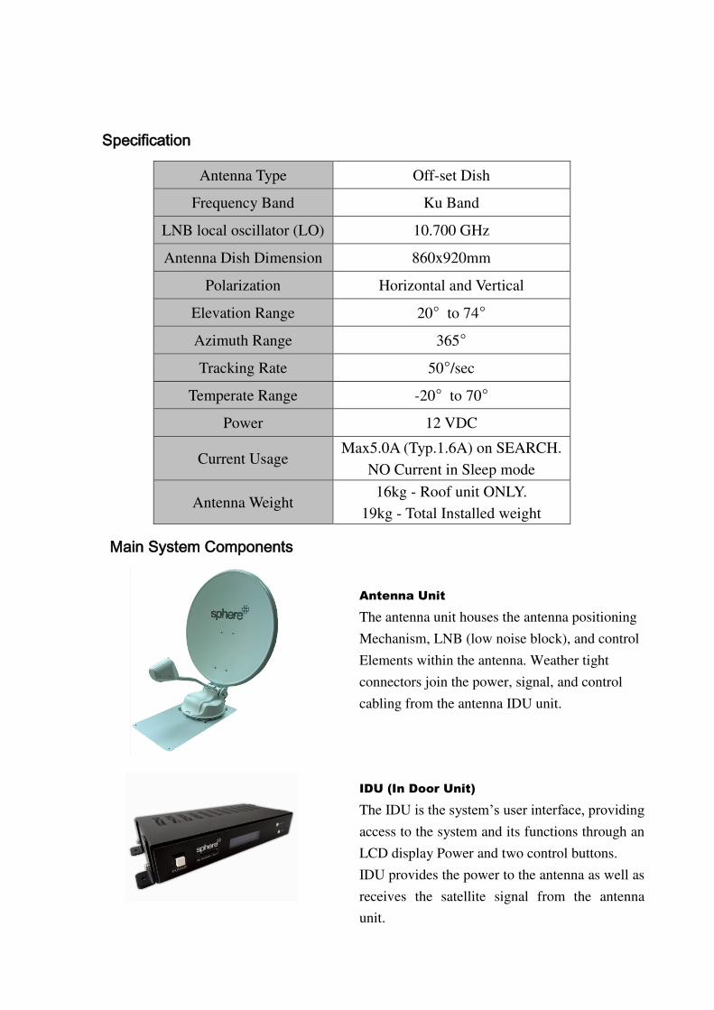
Specification
Antenna Type Off-set Dish
Frequency Band Ku Band
LNB local oscillator (LO) 10.700 GHz
Antenna Dish Dimension 860x920mm
Polarization Horizontal and Vertical
Elevation Range 20° to 74°
Azimuth Range 365°
Tracking Rate 50°/sec
Temperate Range -20° to 70°
Power 12 VDC
Current Usage Max5.0A (Typ.1.6A) on SEARCH.
NO Current in Sleep mode
Antenna Weight 16kg - Roof unit ONLY.
19kg - Total Installed weight
Main System Components
Antenna Unit
The antenna unit houses the antenna positioning
Mechanism, LNB (low noise block), and control
Elements within the antenna. Weather tight
connectors join the power, signal, and control
cabling from the antenna IDU unit.
IDU (In Door Unit)
The IDU is the system’s user interface, providing access to the system and its functions through an
LCD display Power and two control buttons.
IDU provides the power to the antenna as well as
receives the satellite signal from the antenna
unit.
This section offers a general explanation of how to correctly install the Sphere SSA-850
RV Satellite Antenna. Installation of the antenna is recommended to be fitted by a
Sphere Dealer, or RV Accessories fitter.
Unpacking the unit (2 boxes)
1. Open the Main box and remove packing material.
The following items are included in the packaging of the Main Antenna carton.
Item No. Description Quantity
1 Main Antenna Unit 1 each
2 IDU (In Door Unit) 1 each
3 Control Cable (7m) 1 each
4 Coaxial Cable (7m) 2 each
5 Coaxial Cable (1m) 1 each
6 Power Cable (1.5m) 1 each
7 Roof top cable junction box 1 each
8 Roof top cable entry plate 1 each
2. Open the Dish box and remove packing material.
1 85cm Antenna Dish Only 1 each
Ensure all above components are included before proceeding with the installation.
Should any parts be missing, please contact the selling dealer with the units serial
number handy.
Preparing for the installation
Install Tools and Materials
The antenna system is designed for simple installation and setup. However, the
following list of equipment or items should be available during installation of the
antenna.
■ Electric drill and drill bits
■ Socket wrench
■ Silicon sealant
■ Fastener suitable for specific application
1. Verification of the RV’s Power Supply.
■ Confirm that the RV’s power supply is 12VDC. Direct connection to the
Battery/fuse box is recommended with the circuit able to supply a minimum of 5A
current.
2. Verification of the Satellite Receiver and IDU’s attachment and the electricity supply
■ Install the IDU and Satellite Receiver in the interior of the RV.
■ Connect power to IDU and Satellite Receiver.
■ Once the power of IDU and Satellite Receiver is verified, confirm that
both IDU and Satellite Receiver are working normally.
3. Procedure of the satellite’s attachment and installation. ■ Installation of the satellite must be on the flat roof surface area of the RV (Parallel
with the floor of the RV).
■ Connect 2x 7m coaxial cables and 1x 7m control cable to the satellites
Terminals.
■ Connect the IDU and the Satellite Receiver box with each of the coaxial cables.
■ Make sure that the satellite is working normally, once the power is supplied.
Warning: Things to consider when installing the antenna.
■ Turn off the power when attaching or detaching the antenna.
■ Make sure that the attached satellite is fixed on the flat surface.
■ when attaching, ensure that all the products are adhered properly.
■ Ensure that all the cables are connected properly.
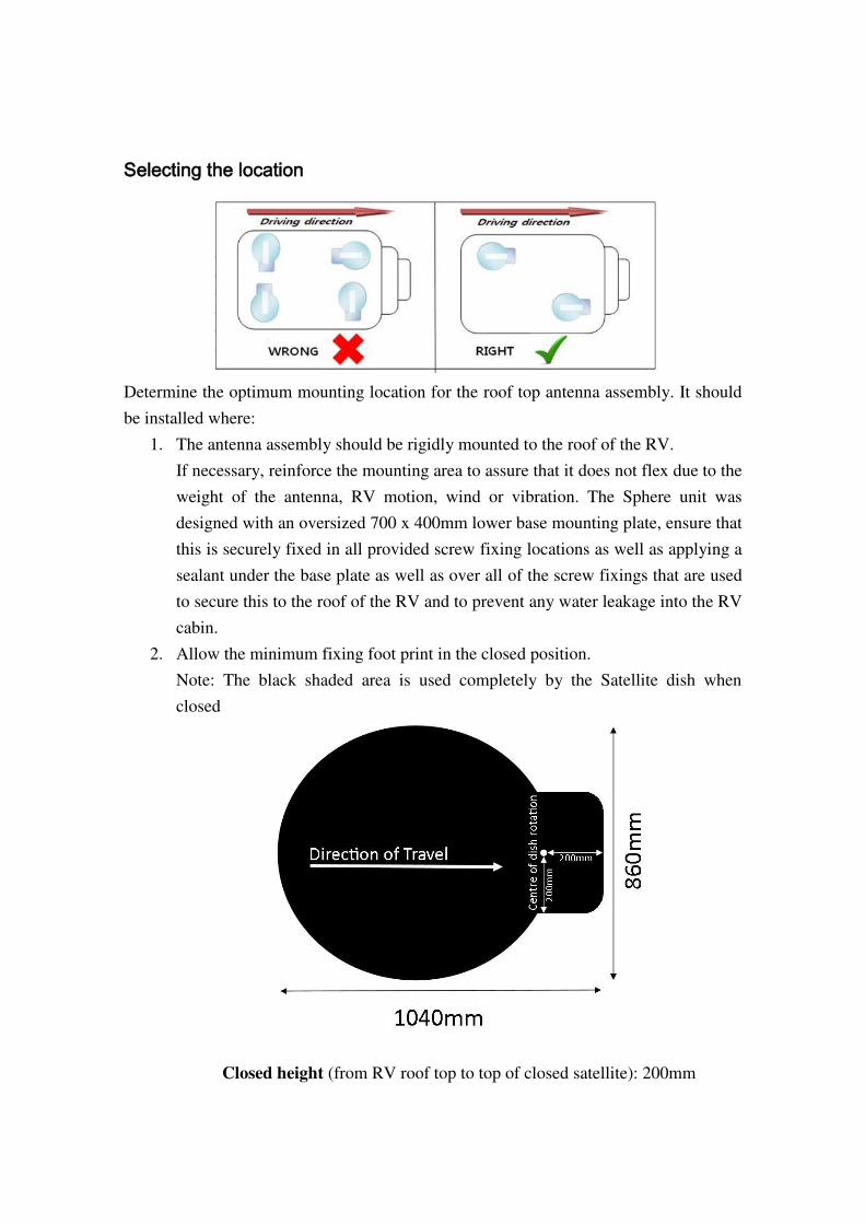
Selecting the location
Determine the optimum mounting location for the roof top antenna assembly. It should
be installed where:
1. The antenna assembly should be rigidly mounted to the roof of the RV.
If necessary, reinforce the mounting area to assure that it does not flex due to the
weight of the antenna, RV motion, wind or vibration. The Sphere unit was
designed with an oversized 700 x 400mm lower base mounting plate, ensure that
this is securely fixed in all provided screw fixing locations as well as applying a
sealant under the base plate as well as over all of the screw fixings that are used
to secure this to the roof of the RV and to prevent any water leakage into the RV
cabin.
2. Allow the minimum fixing foot print in the closed position.
Note: The black shaded area is used completely by the Satellite dish when
closed
Closed height (from RV roof top to top of closed satellite): 200mm
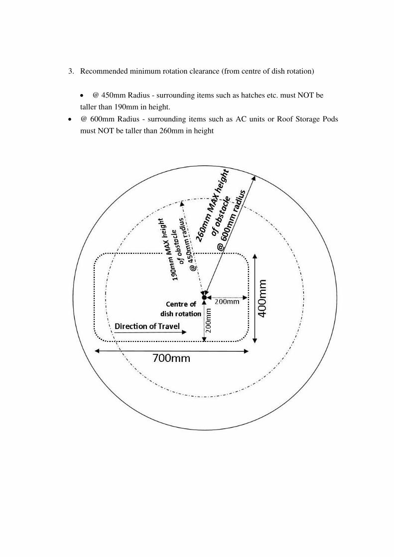
3. Recommended minimum rotation clearance (from centre of dish rotation)
@ 450mm Radius - surrounding items such as hatches etc. must NOT be
taller than 190mm in height.
@ 600mm Radius - surrounding items such as AC units or Roof Storage Pods
must NOT be taller than 260mm in height
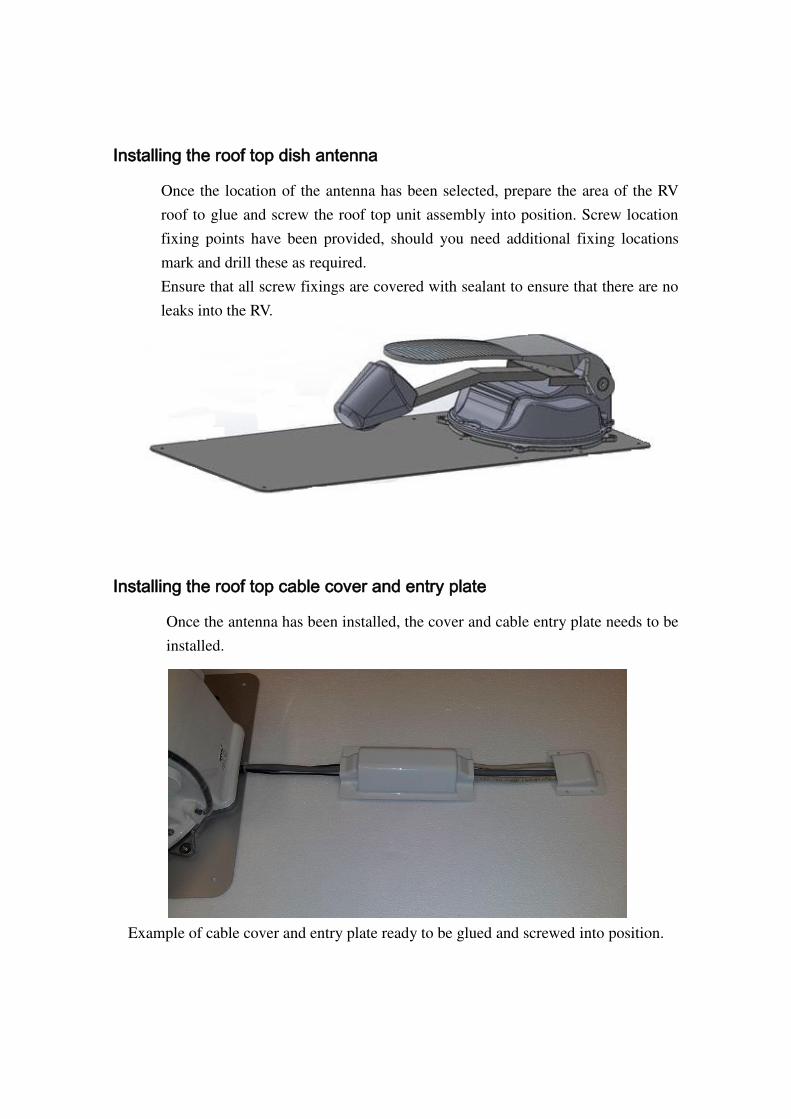
Installing the roof top dish antenna
Once the location of the antenna has been selected, prepare the area of the RV
roof to glue and screw the roof top unit assembly into position. Screw location
fixing points have been provided, should you need additional fixing locations
mark and drill these as required.
Ensure that all screw fixings are covered with sealant to ensure that there are no
leaks into the RV.
Installing the roof top cable cover and entry plate
Once the antenna has been installed, the cover and cable entry plate needs to be
installed.
Example of cable cover and entry plate ready to be glued and screwed into position.

The Cable cover is to be placed between the antenna and the cable entry plate.
This houses the 2x coax feeds and the main control cable connection plug.
The base (ONLY as shown below) of this cover is to be glued and screwed to
the roof of the RV; the top white cover is then placed over this and screwed in
place. NOTE: DO NOT Glue the top white cover in place, this is held to the
base plate with the 4x provided screws.
Drill an entry hole in the required position of 35-40mm to allow the main
control connection to pass through the hole from inside the RV (A smaller hole
can be used if you are to feed the complete loom from the roof down) This hole
is used to pass the 2x coax cables and main control cable through the roof of the
RV. Pass the cables through the hole and ensure that the cable entry plate is
covering the hole and mark the locations for the screw fixing holes to pre-drill
the roof. Apply sealant around the cable entry plate base and ensure that enough
sealant is used at the opening of the plate where the cables exit. Screw the cover
plate down and apply sealant over each screw to ensure no leaks are seen into
the RV.
Example of cable entry plate ready to be glued and screwed into position.
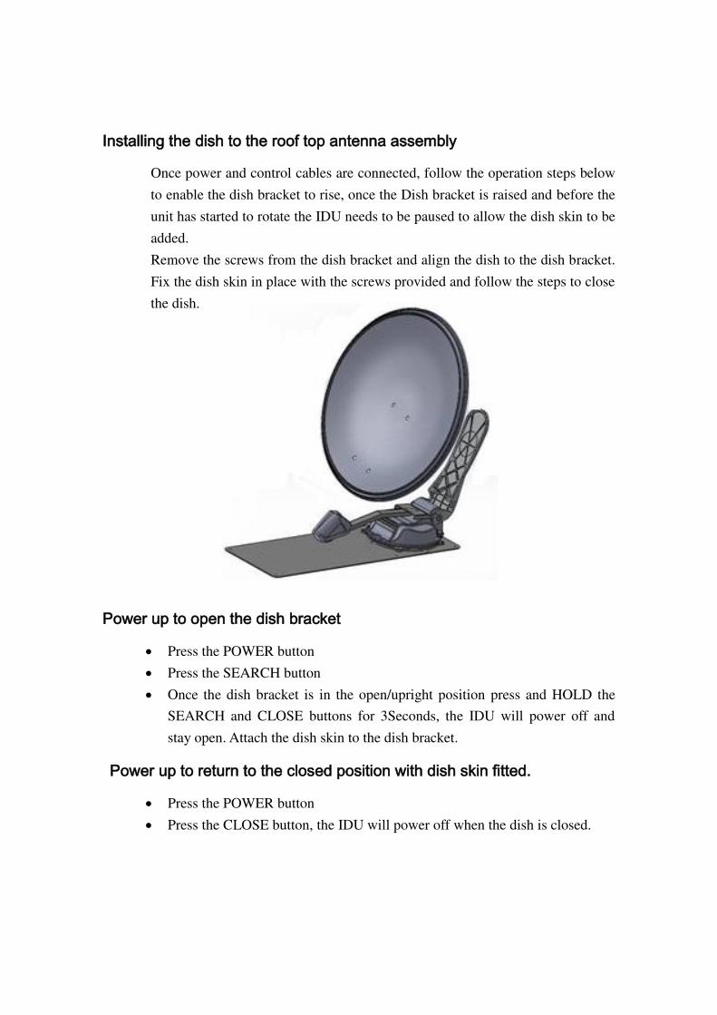
Installing the dish to the roof top antenna assembly
Once power and control cables are connected, follow the operation steps below
to enable the dish bracket to rise, once the Dish bracket is raised and before the
unit has started to rotate the IDU needs to be paused to allow the dish skin to be
added.
Remove the screws from the dish bracket and align the dish to the dish bracket.
Fix the dish skin in place with the screws provided and follow the steps to close
the dish.
Power up to open the dish bracket
Press the POWER button
Press the SEARCH button
Once the dish bracket is in the open/upright position press and HOLD the
SEARCH and CLOSE buttons for 3Seconds, the IDU will power off and
stay open. Attach the dish skin to the dish bracket.
Power up to return to the closed position with dish skin fitted.
Press the POWER button
Press the CLOSE button, the IDU will power off when the dish is closed.
Equipment and cable installation
This offers a general explanation of how to install the IDU and ‘Satellite receiver’ (Satellite receiver is Not supplied in this kit), to the inside of the RV, connecting with
the Main Control Cable and 2x coaxial cables.
1. The 2x Coaxial cables and Main Control cable is routed from the antenna to the
IDU area inside the RV.
2. After once deciding where to place the IDU and satellite receiver, make sure that
both units are placed in a dry and protected area.
3. The IDU and satellite receiver should be placed away from any heat source and in
an area with proper ventilation.
4. Ensure that there are at least 3cm of space around the IDU unit for ventilation and
connection of cables. Do not stack the units on top of each other. (Please
follow the recommendations of the Satellite receiver for its mounting
requirements)
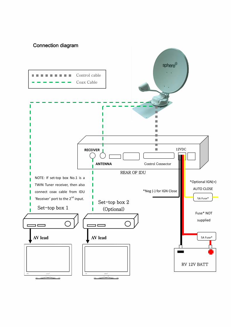
5. The following describes the basic wiring configurations for the antenna system.
Connect the Main Control Cable to the Main cable connection on the rear of
the IDU.
Connect 1x Coaxial cable to the ‘Antenna’ port on the back of the IDU.
Connect the 2nd
Coaxial cable to the Satellite receiver installed into the RV.
Optional(2nd
Satellite Receiver/or Twin Tuner Satellite receiver connection)
Connect the 1m Coaxial cable to the ‘Receiver’ port on the IDU and connect this to the 2
nd Satellite Receiver (or to the 2
nd LNB input of a Twin Tuner
Satellite receiver.)
6. Connecting power to the IDU
RED Wire = Connect to Max.5A FUSED 12V (+) Pos. Power circuit of the
RV house battery.
THICK BLACK Wire = Connect to RV Battery Negative (-) / Common
Ground circuit.
YELLOW*(Optional, May involve extra fitting costs) = Connect to Max.5A
FUSED 12V IGN(+) Pos. Power circuit of the RV Chassis/Start battery
(Ignition feed from Key Switch)
Thin Black = Connect to RV Chassis/Start Battery Negative (-) or Common
Ground circuit.
REAR OF IDU
12VDC
Control Connector
RECEIVER
ANTENNA
RV 12V BATT
5A Fuse*
5A Fuse*
Connection diagram
AV lead AV lead
NOTE: If set-top box No.1 is a
TWIN Tuner receiver, then also
connect coax cable from IDU
‘Receiver’ port to the 2nd input.
Control cable
Coax Cable
Set-top box 1
Set-top box 2
(Optional)
*Optional IGN(+)
AUTO CLOSE
Fuse* NOT
supplied
*Neg (-) for IGN Close
The Sphere SSA-850 RV Satellite Antenna system was designed for its ease of use. This
has been programmed to locate the OPTUS C1/D3 series satellite @ 156E for receiving
of TV broadcast signals. Three (3) Operation zones were added for each Satellite
selection to aid in the search time, and to maximize the signal.
Receiving Satellite TV Signals
Television satellites are located in fixed positions above the Earth’s equator and beam
TV signals down to certain regions of the planet. To receive TV signals from a satellite,
you must be located within that satellite’s unique coverage area. In addition, since TV
satellites are located above the equator, the antenna must have a clear view of the sky to
receive satellite TV signals. Anything that stands between the antenna and the satellite
can block the signal, resulting in lost reception. Common causes of blockage include
trees, buildings, and mountains. Heavy rain, ice, or snow might also temporarily
interrupt satellite signals.
Turning the System On/Off
Since power to the antenna system is controlled by the IDU, you can turn the antenna
on by applying power to the IDU.
Turning on the System
Follow the steps below to turn on your antenna System.
1. Make sure the antenna has a clear view of the sky.
2. Turn on your satellite TV receiver and TV.
3. Press the POWER button on the IDU.
4. When the display powers up. Press the SEARCH button. The IDU will
display the current selected ‘Satellite’ and ‘ZONE’ Number; you may
need to change the satellite selection and/or Zone to suit your viewing
and area requirements. Please refer to the zone map to aid in the correct
Zone selection. To change the desired ‘Satellite’ and/or ‘Zone‘ while the display is flashing quickly (approx. 3 second window), press again the
SEARCH button to toggle to the different ‘Zones’ and satellite selections. Once the correct Satellite and Zone is selected, the IDU will
Lock this selection in memory and will control the Antenna, please
allow the satellite to rotate and search for the selected satellite/zone.
Once the IDU locates the satellite and adjusts the Elevation/Direction
and final LNB Skew setting for your area, the IDU Display will power
OFF to save power.
Turning off the System (To CLOSE the DISH)
Follow the steps below to CLOSE the dish and to turn off your antenna System.
1. Press the POWER button on the IDU.
(This will ‘wake up’ the IDU from its sleep mode.)
2. Press the CLOSE button on the IDU; this will start to close the dish to
the home/closed position ready for travel. Once this is completely
closed the IDU display will power off and go back into Sleep mode.
3. Turn off your Satellite TV receiver and TV.
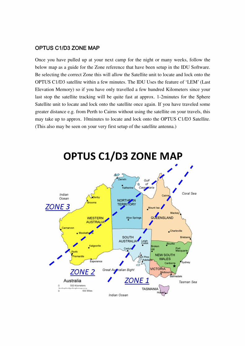
OPTUS C1/D3 ZONE MAP
Once you have pulled up at your next camp for the night or many weeks, follow the
below map as a guide for the Zone reference that have been setup in the IDU Software.
Be selecting the correct Zone this will allow the Satellite unit to locate and lock onto the
OPTUS C1/D3 satellite within a few minutes. The IDU Uses the feature of ‘LEM’ (Last
Elevation Memory) so if you have only travelled a few hundred Kilometers since your
last stop the satellite tracking will be quite fast at approx. 1-2minutes for the Sphere
Satellite unit to locate and lock onto the satellite once again. If you have traveled some
greater distance e.g. from Perth to Cairns without using the satellite on your travels, this
may take up to approx. 10minutes to locate and lock onto the OPTUS C1/D3 Satellite.
(This also may be seen on your very first setup of the satellite antenna.)

SPHERE SSA-850 AVAILABLE SATELLITE SELECTION
Once the correct ZONE has been determined, the IDU has four (4) Pre loaded selections
including.
VAST
PAY TV
OPTUS C1
OPTUS D3
While each of the above is searching for the OPTUSC1/D3 @ 156E the above
selections have been optimized for different services available
.
SPHERE SSA-850 ESTIMATED COVERAGE MAP
Below is an estimated coverage map to show the areas of Australia that the Sphere SSA-
850 is able to lock a satellite. This is only an indication and many factors may reduce
this area of service. On the fringe of these areas it may be seen that the SSA-850 may
lock on to the satellite, though reduced channel may be seen and the whole range of
channels may not be available on the Satellite receiver.
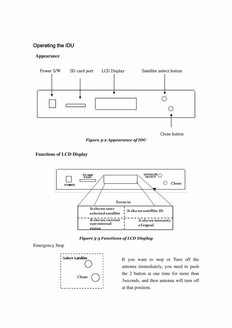
Operating the IDU
Appearance
Figure 3-2 Appearance of IDU
Functions of LCD Display
Figure 3-3 Functions of LCD Display
Emergency Stop
If you want to stop or Turn off the
antenna immediately, you need to push
the 2 button at one time for more than
3seconds, and then antenna will turn off
at that position.
Power S/W LCD Display Satellite select button
Close button
SD card port
Changing Channels
If you have followed the installation and operation instructions, your system should now
be set to the OPTUS C1/D3 satellite @ 156E and the system should have downloaded
the appropriate channel available. When the antenna system and satellite receiver is
properly configured, it is easy to change the channel by using the remote control that
normally comes supplied with the Satellite receiver unit. (Please refer to the user
manual for your satellite receiver)
Software Updating
Satellite Frequency/Transponder Data Changed
Should the antenna fail to find the selected satellite, (and the view is not blocked by
Trees etc.,) the satellite’s frequency data may have changed and a later/revised SW
maybe available to resolve or enhance the operation of the Satellite unit. To confirm if
you have the latest version of Software for your unit, you can visit any authorized
Sphere dealer or contact [email protected] for further assistance. .
Software updates
Should the transponders change in the future, software update may be required. You can
visit any authorized Sphere dealer or contact [email protected] for further
assistance.
New Software will be available at this time. This SW can be sent via email and is to be
copied to a SD card and inserted into the IDU to apply the software update.
Copy the new software file to the SD card (root directory, not in a folder)
With the Power OFF to the IDU, Insert the SD card into the card port on the
IDU
Press the POWER button on the IDU, allow the IDU to copy the new
software file and update the IDU the startup screen will show when the
software is finished updating.
Press the SEARCH button and select the correct zone.
Service and Maintenance
Sphere SSA-850 units do not require any routine service or maintenance within the unit.
General cleaning maybe required at times to ensure the ventilation holes on the IDU are
free and able to allow air flow, this can be wiped with a damp cloth, Please do not use
any harsh cleaners or sprays in or on this IDU.
The Dish skin and LNB cover may need to be cleaned periodically, and this can be
carried out on the RV’s Regular service intervals with a mild cleaner suitable for RV use.
Technical Support and Spare Parts
Should you require any Technical support or Spare parts please contact Coast to Coast
RV Services +61-2-9645-7600 or via [email protected] for further assistance.
Warranty
Sphere SSA-850 units are covered by a twelve (12) month period from the date of
original purchase.
For full warranty terms and conditions please visit
http://www.coastrv.com.au/warranty-policy