rv products inc products inc rb-9050. to ensure that you get optimum results from your ready brute...
TRANSCRIPT

Installation Instructions
ruB t ey Eda lite eR rak B e& Cr oa mbw bo oT
12
Limited Lifetime Guarantee
IN NO EVENT WILL N.S.A. RV PRODUCTS, INC. BE LIABLE FOR ANY SPECIAL, INCIDENTAL, OR CONSEQUENTIAL DAMAGE, RESULTING DIRECTLY FROM POSSESSION, MISUSE OR IMPROPER CARE OF THE READY BRUTE ELITE UNIT.
N.S.A. RV Products, Inc. warrants to the original owner only that this productwill be free from defects in material and workmanship upon original purchase.
The lifetime Guarantee on the Ready Brute Elite unit covers the Ready BruteElite from front to back 100% replacement to the original owner only. The Lifetime Guarantee does not cover damage resulting from tamper, abuse,unreasonable use, mistreatment, negligence or accidental breakage. The Guarantee also does not cover any hardware, cables or any component of the DL-300 In-Dash Light Monitoring System or the safety cables.
Anyone wishing to return merchandise must call to obtain authorization to do so.
1.) 30 day money back guarantee begins on date of purchase.2.) When we receive a return our Q.C. department will inspect the items and determine a refund amount to be issued.3.) Shipping charges are non-refundable and we do not pay return shipping fees.4.) Late returns will be charged a 20% restocking fee.
Returns
RV PRODUCTS INCRV PRODUCTS INC
RB-9050

To ensure that you get optimum results from your Ready Brute Elite please read through the instructions. The Ready Brute Elite provides the towing and braking assistance you need for your towed vehicle, but only when it is used according to the manufacturer’s instructions. NOTE the following:
Base plates need to be installed on your towed vehicle prior to installing the Ready Brute Elite.
N.S.A. Ready Brute Elite Towbars are rated for 8,000 lb. towing capacity. Be sure that the towed vehicle mounting brackets, safety chains and hitch pins are also rated higher than the towed vehicle weight. (Tow car baseplates are not included)
Before you get started
Installing your Ready BrakeMake sure the receiver on your motor home is clean and free from debrisbefore placing the ReadyBrake into the receiver tube. Align the holes of the Ready Brake and your hitch’s receiver tube. Use a standard 5/8” cross pin to secure the Ready Brake in the receiver. The actuator arm on the Ready Brake can travel 3 ½” toward the bumper on the motor home. Allow for clearance. Most motor homes have a standard 6” deep receiver but some are shorter. In case of a shorter depth it is ok to cut 1” off the end of the 2” square tube of the Ready Brake to allow it to fit a shorter receiver.
Step 1. Drill a hole in the firewall where the internal cable conduit will be attached. Depress the brake pedal and mark a spot with chalk on the firewall or floorboard directly across from the depressed brake arm allowing for a straight pull between the brake pedal arm and the hole. (Fig. B)
12354
6
78
910
11
12
13
14
15
16
17
28
29
30
31
32
33
34
35
Available AccessoriesBreak-Away Systemapplies towed vehiclesbrake’s if it ever break’s away from motorhome # RS-5000 “ReadyStop"
Drops, Risers and Extensions 2” drop # H-702 4” drop # H-704 6” drop #H-706 8” drop # H-708 10” drop #H-710 Extension # H-1800
11
Step 2. Make sure there is no obstruction on the engine side of the firewall. Pull back the carpet and drill a 1/8” pilot hole allowing your drill bit to barely go through the firewall. If anything is interfering with this location, drill another pilot hole. Remember to maintain as straight a line as possible.
2
De Fuser
Stop Pulling fuses. Install a De-Fuser then just flip a switch instead.

3
Step 3. Install the Ready Brake conduit fitting. When you have no obstructions in the firewall, enlarge the hole for the steel conduit fitting using a 5/16” bit. Cut a small slit in the carpet where the hole is and slide the steel conduit fitting through the hole from the engine side of the firewall. Secure the steel conduit fitting with the nuts and washers provided. This should protrude through the firewall as little as possible into the car.(Fig B)
AircraftCable
Nylon ConduitFitting
Internal Cable Conduit
Firewall
SteelConduit fitting
Conduit Mounting Bracket
Fig B
If the area where you have drilled the hole for the black cable conduit is congested, put a small dab of silicone (RTV) between the nut and the washer to keep the parts from falling off during installation.
Tip:
10
18
19
20
2122
232425
2627
Ref# Qty Description
1 1 Shock & Spring Assembly2 1 Brake Body Inside3 1 Combo Head4 1 Pivot Block Clamp5 1 3/8x1” Dowel Pin6 4 Actuator Arm7 1 1/4-20x1” Socket Head Cap Screw 8 1 Actuator Arm Clevis9 1 Dust Cover10 1 Clevis Bearing11 1 Swivel End Cap12 1 U-Joint13 1 Stow Strap14 1 Ring Support Block15 2 5/8-1/4X20” SHCS16 1 O-Ring17 2 Billet Elbow18 2 SL-OT19 2 Covers20 2 SL-Pin21 2 SL-Cam22 2 SL- Handle23 2 SL-IT24 2 Dust Cover25 2 Clevis Bearing26 2 Leg End Cap27 2 Towbar to Baseplate Clevis28 1 Sling29 1 Cable Conduit & S.S. Cable W. Thimble30 1 Brake Tie31 2 1/4-20x2 1/4” SHCS32 2 Washer33 2 Split Washer34 2 Nut35 1 Nylon Fitting36 1 3/8” Spring
36
Step 4 At the front (near center) of your towed vehicle, select a location for securing the front end of the Ready Brake black internal cable conduit with the provided nylon fitting. In order to alleviate any slippage of the black conduit, we have added a white nylon fitting to be placed at the front of the towed vehicle. A. If the fitting can be mounted by pushing it through a 3/8” drilled hole in the bumper, baseplate mount or cross member, use the nylon nut that is supplied to hold the fitting in place.(Ex.#1 pg. 4) Or the fitting may be mounted using the clamp provided by placing the clamp around the threaded part of the fitting and bolting to a flat surface of the bumper, cross member or baseplate bracket (as shown in Ex. #2, page 4). B. Cut the black conduit approximately 3/4” short of the place that you have selected to connect it at the front of the of the towed vehicle. (A cut-off wheel like a Dremel tool works well for this)

C. Run about 12” of aircraft cable through the nylon fitting and into the black conduit to get started. (If you don't get it started in this manner it will be difficult to put it through the nylon fitting once the fitting is on the conduit.)
D. Push the nylon fitting over the cut end of the black conduit, then thread the cable through the black conduit.
Towed Vehicle
(Example #1)
(Example #2)
4
How to Install Clevis Connectors on a Ready Brute Tow Bar
After removing the tow bar from the box you will see the end of the legs have no clevises to hook to any brand of baseplate. You will need to install these clevis connectors.
With a 5/16” allen wrench and a 3/4” wrench, take the 5/8” shoulder bolt out of the tow bar leg. While pulling the 5/8” bolt out do not allow the internal knuckle to slide up into the tow bar leg. If it does, you will have to pick the tow bar up and shake it back out. Slide a clevis onto the tow bar leg and reinsert the 5/8” shoulder bolt through the leg and the internal knuckle.
Put the 1/2-13” nylock nut on the bottom of the 5/8” shoulder bolt. Tighten the nut with the allen wrench and the 3/4” wrench until the nut squeezes the ends of the clevis. Do not over tightenso that the clevis can’t pivot back and forth. Make sure the nylon in the nylock nut is past the threads.
Repeat this process for the other leg and you are ready to tow.
Motorhome
9
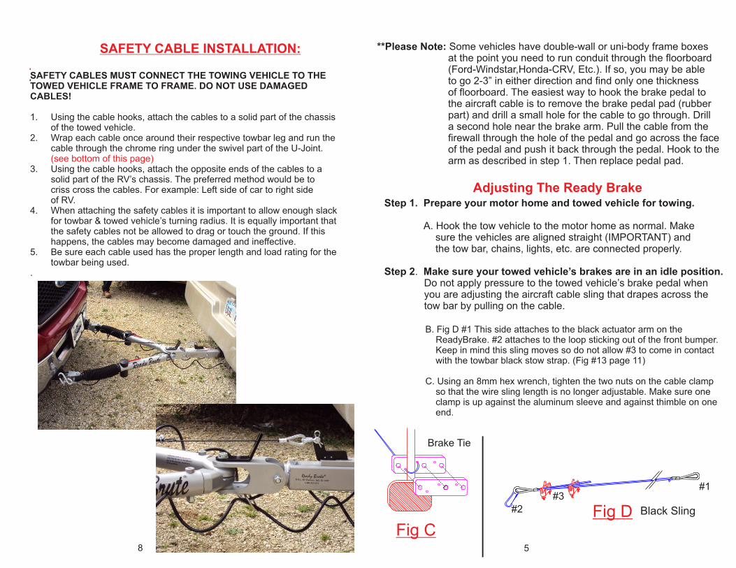
Step 5. Attaching the aircraft cable to your towed vehicle’s brake pedal. A. Place the black brake tie on the bottom of the brake pedal arm. Thread the aircraft cable through the small hole of the bottom piece of the brake tie. Loop it around the brake pedal arm then back through the second small hole on the right.(Fig C) B. Put the top piece of the brake tie on the front of the brake arm. C. Using the 1/4” x 2 1/4” bolts, nuts and lock washers lock the brake tie tightly around the brake pedal arm.(Fig C) Keep in mind if you are working on a vehicle with adjustable pedals to place pedals in highest position. Always tow with pedals in the highest position. D. Trim excess aircraft cable from the bottom of the brake tie. Note: The brake tie and cap screws provided fit the brake arm on most vehicles. (You may need a longer bolt), If you experience any difficulty, please call N.S.A. RV Products at 1-800-933-3372.
Emergency Pin Hole on Ready Brute Tow Bars
Ready Brute tow bars include a feature that will help out in case of failure of anyleg component. We have added a hole in which a ½” bent pin (not included) can beinserted in an emergency situation. It’s not a permanent fix but it will allow you to getto a safe place so you can assess the situation and make repairs. To do this just peelthe clear and red stickers off then insert a ½”bent pin with the tow bar legs fullyextended out. The pin will not fit in unless the leg is fully extended out.
MaintenanceWe included a grease zerk so you can grease the tow bar leg and keep it lubricated.It’s located in front of the black spring cover on the bottom of each leg. Lubricate this with the tow bar leg extended out so the grease will completely lubricate insidethe leg. This does not need to be done more than once a year depending on howmuch you tow.
Grease zerk
½” Bent Pin Hole
8
Brake Tie
Fig C
#1
#2
#3
Fig D
5
SAFETY CABLE INSTALLATION:
SAFETY CABLES MUST CONNECT THE TOWING VEHICLE TO THE TOWED VEHICLE FRAME TO FRAME. DO NOT USE DAMAGED CABLES!
1. Using the cable hooks, attach the cables to a solid part of the chassis of the towed vehicle.2. Wrap each cable once around their respective towbar leg and run the cable through the chrome ring under the swivel part of the U-Joint. (see bottom of this page)3. Using the cable hooks, attach the opposite ends of the cables to a solid part of the RV’s chassis. The preferred method would be to criss cross the cables. For example: Left side of car to right side of RV.4. When attaching the safety cables it is important to allow enough slack for towbar & towed vehicle’s turning radius. It is equally important that the safety cables not be allowed to drag or touch the ground. If this happens, the cables may become damaged and ineffective.5. Be sure each cable used has the proper length and load rating for the towbar being used..
**Please Note: Some vehicles have double-wall or uni-body frame boxes at the point you need to run conduit through the floorboard (Ford-Windstar,Honda-CRV, Etc.). If so, you may be able to go 2-3” in either direction and find only one thickness of floorboard. The easiest way to hook the brake pedal to the aircraft cable is to remove the brake pedal pad (rubber part) and drill a small hole for the cable to go through. Drill a second hole near the brake arm. Pull the cable from the firewall through the hole of the pedal and go across the face of the pedal and push it back through the pedal. Hook to the arm as described in step 1. Then replace pedal pad. Adjusting The Ready Brake
Step 1. Prepare your motor home and towed vehicle for towing. A. Hook the tow vehicle to the motor home as normal. Make sure the vehicles are aligned straight (IMPORTANT) and the tow bar, chains, lights, etc. are connected properly.
Step 2. Make sure your towed vehicle’s brakes are in an idle position. Do not apply pressure to the towed vehicle’s brake pedal when you are adjusting the aircraft cable sling that drapes across the tow bar by pulling on the cable.
B. Fig D #1 This side attaches to the black actuator arm on the ReadyBrake. #2 attaches to the loop sticking out of the front bumper. Keep in mind this sling moves so do not allow #3 to come in contact with the towbar black stow strap. (Fig #13 page 11)
C. Using an 8mm hex wrench, tighten the two nuts on the cable clamp so that the wire sling length is no longer adjustable. Make sure one clamp is up against the aluminum sleeve and against thimble on one end.
Black Sling
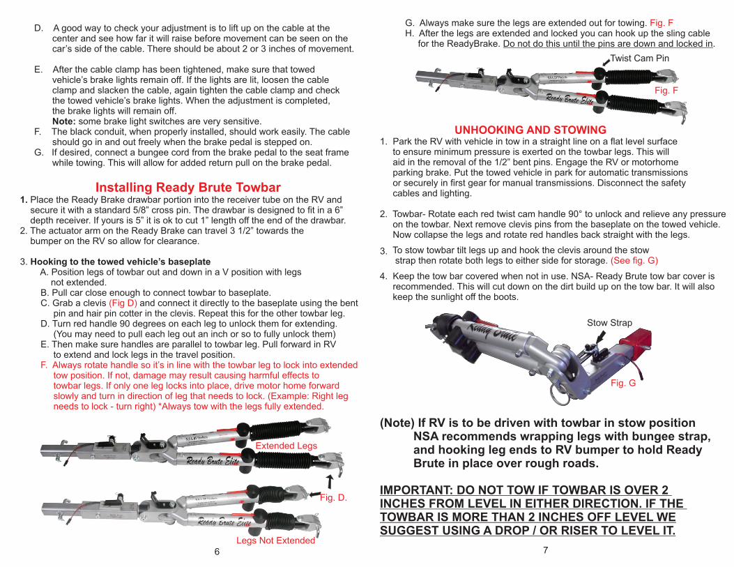
G. Always make sure the legs are extended out for towing. Fig. F H. After the legs are extended and locked you can hook up the sling cable for the ReadyBrake. Do not do this until the pins are down and locked in.
UNHOOKING AND STOWING1. Park the RV with vehicle in tow in a straight line on a flat level surface to ensure minimum pressure is exerted on the towbar legs. This will aid in the removal of the 1/2” bent pins. Engage the RV or motorhome parking brake. Put the towed vehicle in park for automatic transmissions or securely in first gear for manual transmissions. Disconnect the safety cables and lighting.
2. Towbar- Rotate each red twist cam handle 90° to unlock and relieve any pressure on the towbar. Next remove clevis pins from the baseplate on the towed vehicle. Now collapse the legs and rotate red handles back straight with the legs.
4. Keep the tow bar covered when not in use. NSA- Ready Brute tow bar cover is recommended. This will cut down on the dirt build up on the tow bar. It will also keep the sunlight off the boots.
(Note) If RV is to be driven with towbar in stow position NSA recommends wrapping legs with bungee strap, and hooking leg ends to RV bumper to hold Ready Brute in place over rough roads.
IMPORTANT: DO NOT TOW IF TOWBAR IS OVER 2 INCHES FROM LEVEL IN EITHER DIRECTION. IF THE TOWBAR IS MORE THAN 2 INCHES OFF LEVEL WESUGGEST USING A DROP / OR RISER TO LEVEL IT.
To stow towbar tilt legs up and hook the clevis around the stow strap then rotate both legs to either side for storage. (See fig. G)
7
Twist Cam Pin
Fig. D.
Fig. F
Stow Strap
Fig. G
D. A good way to check your adjustment is to lift up on the cable at the center and see how far it will raise before movement can be seen on the car’s side of the cable. There should be about 2 or 3 inches of movement.
E. After the cable clamp has been tightened, make sure that towed vehicle’s brake lights remain off. If the lights are lit, loosen the cable clamp and slacken the cable, again tighten the cable clamp and check the towed vehicle’s brake lights. When the adjustment is completed, the brake lights will remain off. Note: some brake light switches are very sensitive.F. The black conduit, when properly installed, should work easily. The cable should go in and out freely when the brake pedal is stepped on.G. If desired, connect a bungee cord from the brake pedal to the seat frame while towing. This will allow for added return pull on the brake pedal.
3.
6
Installing Ready Brute Towbar1. Place the Ready Brake drawbar portion into the receiver tube on the RV and secure it with a standard 5/8” cross pin. The drawbar is designed to fit in a 6” depth receiver. If yours is 5” it is ok to cut 1” length off the end of the drawbar.2. The actuator arm on the Ready Brake can travel 3 1/2” towards the bumper on the RV so allow for clearance. 3. Hooking to the towed vehicle’s baseplate A. Position legs of towbar out and down in a V position with legs not extended. B. Pull car close enough to connect towbar to baseplate. C. Grab a clevis and connect it directly to the baseplate using the bent (Fig D) pin and hair pin cotter in the clevis. Repeat this for the other towbar leg. D. Turn red handle 90 degrees on each leg to unlock them for extending. (You may need to pull each leg out an inch or so to fully unlock them) E. Then make sure handles are parallel to towbar leg. Pull forward in RV to extend and lock legs in the travel position. F. Always rotate handle so it’s in line with the towbar leg to lock into extended tow position. If not, damage may result causing harmful effects to towbar legs. If only one leg locks into place, drive motor home forward slowly and turn in direction of leg that needs to lock. (Example: Right leg needs to lock - turn right) *Always tow with the legs fully extended.
Extended Legs
Legs Not Extended