rutherford scattering and channeling. useful combination for chemical analysis of surfaces
TRANSCRIPT

Rutherford Scattering and Channeling- A Useful Combination for Chemical Analysis of Surfaces W. D. Mackintosh and J. A. Davies Atomic Energy of Canada Limited, Chalk River Nuclear Laboratories
T HE INTERACTION of accelerated ions with solids provides a num-
ber of techniques for the chemical analysis of surface layers. Prob- ably the simplest of these is the use of wide-angle elastic or Rutherford scattering, but, although several such scattering investigations have been reported (1-6) , the method has not found very wide acceptance. However, the picture is now chang- ing rapidly-primarily because of the widespread use (7-8) of elastic scattering for studying the channel- ing behavior of accelerated ion beams in single crystals. As a by- product of these channeling studies, we find that the elastic scattering yield can give valuable information not only on the number of impurity atoms in the crystal surface but also on their lattice location within the unit cell. Furthermore, channel- ing enhances considerably the sen- sitivity of the analysis, particularly in the case of low-mass impurities. This Report reviews the theory and practice of the elastic scattering method, and describes how channel- ing can be used to assist the chemi- cal analyst.
Theory
When a beam of monoenergetic particles strikes a surface, some will be scattered from the material, los- ing energy in an amount propor-
tional to the mass of the atom struck. Further, the number of par- ticles so scattered is a function of the number of atoms present. Hence, by measuring the energy and counting the number of the energing particles, the identity and number of atoms in the solid can be determined.
The energy of the emergent par- ticles E , is related to the incident energy E , by the equation
E , = k2E, where iii, cos 8, + ni, (1) k =
M, + lM, M , is the mass of the incident ion, M , the mass of the struck atom, and 8, is the laboratory scattering angle (Figure 1).
This equation holds only for scat- tering from surface atoms. If the incident particle does not suffer scattering in the surface layer, it will lose energy by ionization and excitation processes as i t proceeds to lower layers. Thus, just before being scattered, it will have an en- ergy Eo’. The scattered particle will also be slowed down on its way back to the surface and will emerge with an energy E,‘. If the rate of energy loss by the slowing down processes is given by the stopping power S, then the energy of a par- ticle emerging from a depth z below the surface is expressed by
L 0 0
where the first and second integrals are the energy losses along the in- coming and outgoing trajectories Z, and 1,. S, and S,, the mean values of the stopping power, depend on the energy of the particle; in the case of single crystals, S, also de- pends on whether or not the beam is channeled. The geometric rela- tionships between e,, 8, and 8, are illustrated in Figure 1.
Some facts relevant to the use of elastic scattering for analysis can be inferred from these equations:
(1) If a beam of monoenergetic particles strikes a thick polycrys- talline or amorphous solid, the en- ergy spectrum of the elastically scattered particles is similar to tha t shown for silicon in Figure 2. It is characterized by a sloping plateau terminated by a sharp edge. The sharp edge represents the energy E , obtained by scattering from the surface layers; its position is deter- mined by the masses of the incident particle M , and scattering atoms M , (in this case the masses of the helium ion and silicon atom respec- tively), according to Equation 1. The slope of the spectrum edge is
2 6 A ANALYTICAL CHEMISTRY

REPORT FOR ANALYTICAL CHEMISTS
r X 1
V A C U U M 1 T A R G E T
Figure 1. Schematic diagram showing the geometric relationship of t he various angles involved in the elastic scattering equations
due to the finite resolution of the detector. Counts recorded a t lower energies are derived from particles scattered from progressively greater depths. As x increases, the energy E,' decreases according to Equa- tion 2 .
( 2 ) If the thick solid is covered with a thin (-100 A or less) film of atoms of greater mass than the substrate, a spectrum similar in shape to tha t shown for gold on sili- con in Figure 2 is obtained. At en- ergies above the silicon edge, a sharp peak is observed due to scattering from the heavy gold atoms on the surface; its position also is given by Equation 1, where AI2 is now the mass of the gold atom. If the gold film had been much thicker (-0.1 pm or more) the width of the peak would have increased in the direction of lower energy. At the same time the edge of the sub- strate would have retreated to lower energies because Eo', the en- ergy of the particle entering the substrate, would have been de- creased significantly by the stop- ping power of the surface film.
(3) Conversely if the solid is covered with a thin film of an ele- ment whose mass is less than that of the substrate, the peak represent- ing its energy distribution is super- imposed on the plateau, (cf. Fig-
ure 7). For such a combination the scattering technique is not particu- larly useful except (as we shall see later on) in the case of single crys- tals. (4) Equation 1 indicates tha t the
energy difference between the im- purity peak and the edge of the plateau increases with the mass iM, of the incident particle. For opti- mum resolution, the projectile mass should be selected so tha t particles lose approximately 5070 of their initial energy on being scattered through the chosen scattering angle.
( 5 ) Mass resolution also im- proves with increase of scattering angle O s , although, as will be seen later, this must be compromised with a decrease in yield.
(6) Increasing the energy of the incident particle would appear to improve the differentiation of masses, particularly a t large scat- tering angles, but this also decreases the yield. Furthermore a t higher energies the chance of the incident particle undergoing a nuclear reac- tion rather than scattering in- creases. In these cases, not only is the particle lost, but the secondary particle produced in the reaction may be detected and contribute to the count rate. I n general, penetra- tion of the Coulomb barrier a t mod- est energies, Le., <2 MeV, is less likely the greater the masses of the
I i i . I
C - Z L - G 5 E Y F Q ' 3 1 d e
Figure 2. Energy spectrum of hel ium ions scattered f rom a silicon target whose surface had been contaminated with-1 mono-layer (0.5 pg/crnz) of gold
incident and target particles ; how- ever, no safe guide lines can be laid down.
(7) The difference in energy of particles scattered from two ele- ments of similar mass number is very small, for example approxi- mately 5 keV between manganese and iron for a 1.6 MeV helium beam. A typical solid state detector has an energy resolution around 20 keV and hence cannot be used in this case, unless much higher ener- gies are employed.
Wc will nom consider the rela- tionship between the numbers of atoms present in a target and the number of scattered particles de- tected. The scattering probability, &, into thc solid angle, do, is given by the Rutherford scattering for- mula
where Z, and Z, are the atomic numbers of the incoming particle and target atom. respectively; M, and M2 are their masses; E is the energy (in MeV) of the particle be- fore being scattered; and @, is the scattering angle. The scattered yield per coulomb can be directly calculated from this equation.
It follows from this equation:
VOL. 41, NO. 4, APRIL 1969 2 7 A

Report for Analytical Chemists
(1) The higher the atomic num- ber of the target atoms, the greater is the number of counts per unit time. This again favors the anal- ysis of heavy elements on or in light matrixes. Conversely when the analysis of a light element on a heavier substrate is attempted not only are the impurity counts super- imposed on the substrate plateau (as a consequence of Equation 3 ) , but the relative cross sections are in the wrong direction, thereby wors- ening the statistics.
(2) Small scattering angles en- hance the sensitivity, but a t the ex- pense of poorer mass resolution.
(3) Equation 3 is valid for the outer layer of a target only. As we have already seen, when the in- cident particle traverses a number of atomic layers before being scat- tered, its energy is decreased by the stopping power of the material. Thus the scattering cross section for nuclides located some distance be- low the surface is increased some- what. An expression relating the yield of scattered particles to the depth and to the stopping power is given in Reference ( 2 ) .
Equipment
For most analysts using elastic scattering methods, the choice of accelerator has presumably rested on what was accessible. hfost work has been carried out with Van de Graaff accelerators, particularly the 2 MeV machines. The energy spread a t the target is low, typi- cally 20.1% of the mean energy. Beam currents up to 10 p A are ob- tainable; for most scattering ex- periments -lo-? pa is sufficient. The use of higher energy Van de Graaff machines has been reported ( 4 ) and one 600 keV heavy ion accelerator ( 7 ) . Turkevich (6) used an a-emitting source of 242Cm for his experiments, but he had to meet the exacting requirements of transporting the entire apparatus to the moon (Surveyor lunar mis- sions September 1967 and January 1968).
The forms of target chambers and target holders vary greatly, but a few guidelines for design can be set down. It is useful to have one port, of the target chamber de- signed to take several different
forms of target holders tha t can be interchanged. If the setup is to be used for charged particle activation analysis as well, another port capa- ble of accepting interchangeable de- tectors is also good practice. The solid-state detector for elastic scat- tering analysis should be mounted so that the observed scattering angle can be altered.
We have found i t convenient to use three different types of target holder. One has provision for fast- ening samples to the outer circum- ference of a disk which can be rotated from outside the chamber without breaking the vacuum, thereby bringing successive samples into the beam. Another has pro- vision for moving a sample across the beam so that concentration gradients in a surf ace plane may be located and determined. The tra- verse is 3 cm in each direction. The third holder is a goniometer having two independent axes of rotation so that any desired crystallographic axis or plane of a single crystal may be oriented with respect to the incoming beam. All three devices enable the sample to be electrically insulated from the rest of the cham- ber. The sample is connected to a current integrator.
When one irradiation must be exactly comparable to another (ir- radiations of a sample and a com- parative standard), the method for measuring the integrated beam cur- rent must account for ions scattered from the target and for secondary electron emission (1,4,5), at MeV energies, however, their effects are usually quite small ( 5 10%).
Two quite different systems for detection and energy measurement of the scattered particles have been used. Most common is the com- bination of a small, high resolution solid state detector with a multi- channel pulse height analyzer. Such detectors are inexpensive and read- ily available. They also subtend a large solid angle and thus make it possible for enough counts for good statistics to be accumulated a t low beam currents-thereby minimiz- ing sputtering and excessive heating of the target. The solid state de- tectors have typically a resolution of approximately 20 keV FWHM a t 1 MeV, and hence cannot dis- tinguish between elements whose
masses differ by <207L. In addi- tion we have found it convenient to use three or four single-channel analyzers and scalers in parallel to the multi-channel pulse height analyzer so that data in selected channels can be recorded sepa- rately.
The alternative detector system, a high resolution magnetic or elec- trostatic spectrometer gives con- siderably better mass resolution particularly a t low energies, and can almost distinguish between the isotopes of an element ( 1 ) . How- ever, such instruments are much less sensitive, require much higher beam currents, and are not so readily available.
Quantitative Analysis
One important advantage of the elastic scattering technique, com- pared to other methods such as ac- tivation analysis, is tha t quantita- tive analyses can be obtained from a single measurement without hav- ing to prepare any comparative standards-provided the bombard- ment is carried out a t energies where the Rutherford scattering law (Equation 3) is valid. Under such circumstances, the number ni of counts observed in an impurity peak (cf. Figure 2) is related to the number Ni of impurity atoms/cm* of surface as follows
n 1. = fZi2Ni (it) (4) where Zi is the atomic number of the impurity, (it) is the integrated beam current, and f is a constant that depends only on the scatter- ing angle, the geometry of the de- tector, and the energy and atomic number of the projectile.
Similarly, the number, n,, of counts in one channel of the sub- strate spectrum (measured just be- neath the surface) is related to the number, AT,, of substrate atoms con- tributing to tha t channel by
Consequently, n, = f Z s Z N Q (it) (5)
or
The 3 is evaluat,ed directly from n* the observed energy spectrum, and
28 A e ANALYTICAL CHEMISTRY
Report for Analytical Chemists
nsr the number of substrate atoms contributing to a given channel can be easily calculated provided the rate of energy loss dE/dx in the substrate is known. This method of analysis eliminates the need not only for comparative standards but also for precise measurement of the integrated beam current. Hence the problems of secondary electron emission, etc., are completely avoided. I t s success depends, of course, on the validity of the Ruth- erford scattering law, but with 1-2 MeV helium (or heavier ions) as projectiles this assumption does not introduce significant error. With protons, however, or with higher energy projectiles, resonance effects can cause serious departures from the Rutherford 1 a w . h such cases, the more conventional pro- cedure of using a comparative stan- dard should be adopted.
The preparation of comparative standards when necessary, is rela- tively easy. Films can be produced by such processes as electrodeposi- tion, evaporation or thermal de- composition of organic vapors. The thickness can be obtained by various methods, for example, by weighing and by such devices as counting deposits prepared from radioactive materials of known specific activity. References to such procedure are given by Semmler, Tribby, and Brugger ( 3 ) . The sub- strate does not interfere with the elastic scattering yield of these sur- face layers, but it is advisable to deposit the film on the same ma- terial as the sample to be analyzed; otherwise, the secondary particle yields may differ and giye inte- grated beam current readings which arc not comparable. Further, the total count rate may differ suffi- ciently that dead time losses would have to be evaluated and correc- tion> applied.
Applications
Most of the successful quantita- tive applications reported in the literature are concerned with the determination of thin films on sub- strates of lower mass. Rubin (1) used 2 MeV protons plus a mag- netic spectrometer to analyze steel surfaces tha t had been exposed to an explosion. H e observed peaks
which were identified (by Equa- tion 1) as silver/antimony and lead/mercury and calculated the concentrations. Samples of electro- statically precipitated aerosols on aluminum foil were similarly ana- lyzed and carbon, oxygen, silicon, and sulfur were found. The oxy- gen, sulfur, and silicon peaks cor- responded to deposits of 5, 0.13, and 0.3 pg/cm?, respectively. The car- bon peak was disregarded because of the well known buildup of car- bon on targets by evaporation of hydrocarbons from diffusion pumps.
Anders ( 5 ) reported the deter- mination of silver on glass surfaces in amounts ranging from 10 to 49 pg/cm2 and chromium on mag- nesium from 20 to 150 pg/cm2. He also used 2 MeV protons but de- tection and energy analysis was performed with a solid state de- tector and pulse height analyzer. Peisach ( 4 ) , bombarding with He', found 1-10 pg/cm2 gold on alumi- num. Elastic scattering of a par- ticles and activation by the same particles provided Patterson, Tur- kevitch, and co-workers the means for analyzing the lunar surfaces (9 ) .
I n our laboratories, we have dc- termined as little as 0.003 pg/cm? of gold and copper on the surface of wafers cut from single crystals of silicon ( I O ) . The objective of the analysis was to see if contaminants from etching or treatment solutions used in the production of solid state devices were adsorbed on the wafers and if so, to determine how the amount of deposit varies with (i) the concentration of contaminant in solution, (ii) the orientation of the crystallographic surface, and (iii) the conductivity and resistivity type of the wafer. Thus, there were many samples to analyze, yet each required less than 10 minutes, em- ploying a beam current of 5 nA. hTo comparative standard was ir- radiated because the incident beam of He+ a t 1 MeV produced no nu- clear reaction to interfere with the count of the elastically scattered particles. The number of contami- nant atoms was obtained by relat- ing the relative yields through their Z2 dependence. (Equation 7 ) .
Another practical application in our laboratories was the determina-
tion of zirconium on mild steel sur- faces. The zirconium had been dis- solved in a liquid metal coolant circulating in mild steel piping and was intended to inhibit corrosion by deposition on the steel. Radioactive zirconium deposits of known spe- cific activity were used for cali- bration.
Sippel ( 2 ) has described an ele- gant application. From the energy spectrum of emitted particles, he determined a concentration gradi- ent of gold diffused into copper. I n this way, much thinner diffusion depth could be studied than by the mechanical and chemical sectioning techniques usually employed. A similar procedure has been used by Powers (11) to study the concen- tration profile of heavier ions im- planted into Be, C, and A1 targets.
Elastic Scattering in a Single Crystal-Channeling
We will now consider how-in a single crystal substrate-the channeling phenomenon can be uti- lized by the analyst to extend the applications of the scattering tech- nique.
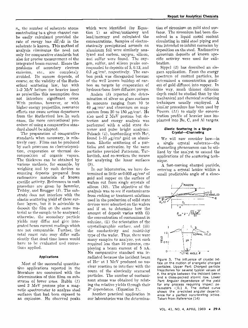
A fast-moving charged particle, entering a crystal lattice within a small predictable angle of a close-
.-- , , , !(A)\
0 TILTING ANGLE e
Figure 3. The influence of crystal lat- t ice on the mot ion of energetic charged particles. Upper Part: Charged particle trajectories for several typical values of e, the angle between the incident beam and a close-packed atomic row. Lower Part: Angular dependence of the yield fo r any process requiring impact pa- rameters <0.1 A. The dotted curve shows the predicted angular depend- ence fo r a perfect nonvibrating lattice. Taken f rom Reference (14)
VOL. 41, NO, 4, APRIL 1969 29A

Report for Analytical Chemists
packed atomic row or plane, be- comes channeled-ie., i t becomes steered by successive gentle colli- sions, and is thereby prevented from having violent collisions with individual lattice atoms. In other words, as long as i t remains chan- neled, a particle will not undergo elastic scattering ; hence, the ob- served yield will be reduced drasti- cally from that obtained on bom- barding the crystal along a random direction. This phenomenon can serve as a tool for studying certain properties of crystalline material. Some of these are of direct interest to the chemical analyst.
Lindhard (12) has provided an accurate theoretical description of the actual steering mechanism. The principles involved are summarized in Figure 3. One can distinguish three different types of particle tra- jectory. An energetic charged par- ticle, moving through a lattice within a predictable critical angle of an atomic row (or plane), is steered by successive gentle colli- sions (trajectory A ) , and is thereby prevented from entering a forbid- den region around each lattice row. The radius of this forbidden cylin- der is given by the Thomas-Fermi screening distance, a, which is typi- cally 0.1-0.2 A. When the incident angle 8 is much larger than q, the particle has no "feeling" for the existence of a lattice, and so has a random trajectory (trajectory C) . There is also an intermediate region (via. when 8 is only slightly larger than +) in which the particle tra- jectory (trajectory B ) actually has a slightly enhanced probability of being close to the atomic rows and, hence, of undergoing violent colli- sions; however, this region is not quantitatively reproducible, and so is not of much use to the analyst.
The lower part of Figure 3 illus- trates the predicted orientation de- pendence of the yield curve for any close-encounter process (i.e., a process having an impact param- eter less than a). Experimental in- vestigations of wide-angle Ruther- ford scattering (7) have verified that such large attenuations do occur. The agreement between the predicted and measured orientation dependence is quite reasonable (151, as can be seen in Figure 4.
Figure 4. Experimental and calculated d ip in Rutherford scattering yield for 480 keV pro-
'.?---. ~~~~~i tons incident along a
12 >
CL I (100) direction of a value
2030 TILTIlvC GNGLE 5 0 - P R 0 V l v ENERGY 3 0 M e V
5 200 ' i (I
50" I C Y 50' 200' 253" 300' 350'
A Z I M U - H A L A N G L E Figure 5. Rutherford scattering yield obtained on rotation of a tungsten crystal around the (100)axis with a tilt angle of 5.0" between the rotation axis and the incident proton beam (incident energy 3.0 MeV)
The critical angle is given by equa- tion
4
where 2, aLd 2, are the atomic numbers of the incident particle and lattice atom, respectively, e is the electronic charge, E is the in- cident particle energy, and d is the distance between adjacent atoms along the chosen atomic row.
To utilize channeling, i t is first necessary to orient precisely the crystal target with respect to the incident beam. Fortunately, this orientation can be done quite easily by means of the channeling effect itself (14), using the same elastic scattering process as in the analyti- cal studies described above. If the crystal is mounted on a suitable goniometer allowing rotation of the crystal a t a certain tilting angle to the beam, and is then rotated through 360", a yield curve like the one shown in Figure 5 is obtained. The sharp attenuations occur as the various close-packed planes are successively aligned with the in-
cident beam. A stereogram (Figure 6) can then be constructed by marking off on the circumference of a circle, the azimuthal angles a t which these planar "dips" in yield occur. By properly connecting the pairs of points tha t correspond to intersections of the same plane, we readily obtain the exact location P of a major crystal axis-in this case the (110.). This whole opera- tion can be performed in situ prior to the analysis, and requires only 15-30 minutes of time. The beam can then be aligned exactly with the major axis by setting the goniom- eter a t the azimuthal and tilt angles corresponding to the point P on the stereogram.
One important advantage of channeling to the analyst is tha t it enables the scattering from the sub- strate to be suppressed drastically, and thus enhances the sensitivity for detecting trace amounts of sur- face contaminants. This is particu- larly true in the case of low-mass impurities on a heavier substrate, where, as noted earlier, the scat-
3 0 A * ANALYTICAL CHEMISTRY

Insert
Titr -
Normal solutions In no time
puna upper membrane P u n a lower membrane rlnw and make up to volume
Titrisol ampoule;) c a v e weighing, dissoiving and stafidaidising the titre
Titrisol ampoules
Titrisol ampoules
TitrisoI ampoules
due to their construction permit c of the accurate dosage into the
save time, space and weight
are unbreakable, storable and always ready for use
Titrisols are absolutely reliable (titration exactness 2 0,2%) Please ask for our special leaflet
Sole distributors in the United States: Brinkmann Instruments, Inc., Cantiague Road, Westbury L. I., N. Y.
E. MERCK AGaDARMSTADTaGERMANY Circle No. 55 en REldeIS’ Service Card
232/1-EUS
Here's a BETTER l iquid Syringe ... and it LASTS ! It's the Series "C" Pressure-Lok Liquid Syringe
SUPERIOR ACTION
TEFLON.TIP PLUNGER
STARTS OUT AND STAYS LEAKTIGHT to 150 psi
NO "FREEZE.UP"
EXTENDED LIFE
INTERCHANGEABLE PARTS
OPTIONS AVAILABLE
"Teflon" i s a registered DUPOnt Trademark
P. 0. BOX 15119 * BATON ROUGE, LA. 70815
. . . . . . . . . . . . . . ..................... . . . . . . ,
want more information on
Lok liquid syringes are better.
&& ' why Series "C" Pressure-
N A M E
T I T L E
C O M P A N Y
ADDRESS
CITY
STATE ZIP-
Circle No. 140 on Readers' Service Card See ACS laboratory Guide for A11 ProductsISales Office 32 A ANALYTICAL CHEMISTRY
Report for Analytical Chemists
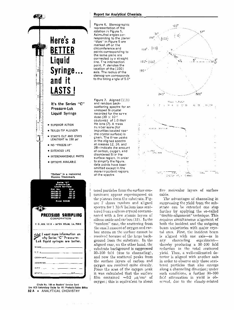
Figure 6. Stereographic 100" ---. _-- -_
, \570 '\
representation of the rotation in Figure 5. Azimuthal angles cor-
"dips" in Figure 5 are marked of f on the
points corresponding to the same plane are connected by a straight
point, P, denotes the location of the (100) axis. The radius of the stereogram corresponds t o the tilting angle of 5.0"
responding t o the planar 1399 '\ { loo} I1 1 01 / ' \, 131'
, circumference and 159' ! I i o )
. -_ +?e-- ~ --__ line. The intersection 180"- {loo} \% 5" ~ - -a$
193"
Figure 7. Aligned (111) and random back. scattering spectra for an undoped Si crystal recorded for the same dose (30 x 10-5 coulomb) of 1.0-MeV He ions (7). A mass number scale (for impurit ies located near the crystal surface) is given. The three peaks in the aligned spectra at masses 12, 16, and 28-indicate the amount of carbon, oxygen, and disordered Si in the surface region. In order t o simplify the figure, data points have been omit ted except in the m0re.i m porta n t reg ions of the spectra
tered particles from the surface con- taminant appear superimposed on the plateau from the substrate. Fig- ure 7 shows random and aligned spectra for 1 MeV helium ions scat- tered from a silicon crystal contami- nated with a few atomic layers of silicon oxide and carbon ( 1 5 ) . I n the "random" case, the scattering from the small amount of oxygen and car- bon atoms on the surface caniiot be resolved because of the large back- ground from the substrate. I n the aligned case, on the other hand, the substrate background is suppressed 30-100 fold (due to channeling), and now the scattered peaks from the surface layers of carbon and oxygen are resolved quite cleanly. From the area of the oxygen peak i t was calculated tha t the surface film contained -0.2 pg/cm2 of oxygen ; this is equivalent to about
five molecular layers of surface oxide.
The advantages of channeling in suppressing the yield from the sub- strate can be extended one step further by applying the so-called "double-alignment" technique. This requires simultaneous alignment of both the incident and the outgoing beam trajectories with major crys- tal axes. First, the incident beam is aligned with one axis-as in any channeling e x p e r i m e n t thereby producing a 30-100 fold reduction in the total scattered yield. Then, a well-collimated de- tector is aligned with another axis in order to observe only those scat- tered particles that also cmerge along a channeling direction; under such conditions, a further 30-100 fold attenuation in yield is ob- served, due to the closely-related

Report for Analytical Chemists
..-.. ,
. ’ . . . , .I. .. _ . . .’., ,: ’.
Figure 8. Energy spectrum of 1 MeV H e T ions scattered 70.7” in tungsten. Incident direction = <111) axis. Exit direction = <lil> axis. Taken f rom Reference (16)
phenomenon of “blocking.” Hence, an overall attenuation of 103-104 can be achieved. The advantage of this “double alignment” procedure has been beautifully demonstrated by E. Bggh (f6), using tungsten crystals, and is illustrated in Figure 8. Even in this rather unfavor- able (if?., high 2) target, the carbon and oxygen peaks are clearly re- solved, even though they corre- spond to only 1.0 and 0.3 pg/cmZ respectively-indicating tha t with double-alignment the sensitivity for low-mass impurities can be ex- tended to much less than one atomic layer. The unlabelled peak a t 840 keV corresponds to 0.1 pg/cm2 of a surface contaminant around mass 40; i t is probably due to potassium contamination from an aqueous KOH treatment tha t had been used
*
i
0
Figure 9. A two-dimensional model 11. lustrating how the channeling phe- nomenon can be used t o locate foreign a toms in a crystal (9). As shown by the table, three typical sites fo r a foreign a tom 0 , 0, and X can be uniquely dis. t inguished by studying the channeling behavior f i rst along the 01-, and then along the 1l .d i rect ion
to clean the tungsten surface before the analysis.
I n using channeling to suppress the background yield from the sub- strate, the analyst is of course mak- ing one important assumption : namely, tha t the scattering yield from the impurity atoms does not depend on the orientation of the underlying crystal substrate. This assumption is justified whenever the impurity atoms are contained in an amorphous or polyvrystalline surface layer. But, if they have be- come embedded within the host lat- tice (for example, by ion implanta- tion or by diffusion), then the validity of the assumption depends critically on what type of lattice site they occupy. In fact, by study- ing the validity of this assumption --i.e., by comparing the orientation dependence of various impurity peaks with tha t of the substrate, i t is possible to establish the exact lattice location of specific foreign atoms within the unit cell. Such information is particularly valuable in the doping of semiconductors, and has led to the recent wide- spread use of the scattering tech- nique in analyzing ion-implanted Si and Ge (Refs. 15-f 9).
Let us therefore consider briefly how this orientation dependence of the scattering yield can swve sts a tool for locating foreign atoms in crystals. Figure 9 shows the prin- ciples involved for a simplified two dimensional lattice, where 0 , X and
represent several possible posi- tions for an impurity atom. The interaction between a channeled beam and foreign atoms in the crys- ta l will not show any attenuation in yield, provided the foreign atom is located in the allowed space for the channeled beam. Hence, inter- stitial atoms will not show any at- tenuation, a t least along some main direction (k., 0 along the (01) di- rection and X along the (11) direc- t ion) . On the other hand, if the foreign atom is situated along a row (k., in the forbidden space for the channeled beam), then a large de- crease in the yield of the process will be observed whenever the beam is aligned within the critical angle of that particular row. For a true substitutional position, such as (a), a large attenuation will be observed for all close-packed direc-
new from SaS
Ready Plates TLC
Extremely uniform coating on glass plates. 10 x 20 cm (50 per package). 20 x 20 cm (25 per package). Ready Plates individually wrapped in poly- ethylene bags. Media offered as cellulose powder or silica gel with or without binder of starch or gypsum. Special polyamid, acetylated and ion exchange plates. Working instructions available for Ready Plate separation of the follow- ing groups.*
Alkaloids Lipophylic dyes Alpha amino acids Carcinogenic Bleaching agents hydrocarbons Carotinoids Amines Cations: Ca, Mg, AI, Fe Monoazo dyes Gasoline with Oligosaccharides tes t dyes Reactive dyes Seed oils Addictive drugs Fish oils Sugars Test dyes Chlorophylls and related natural colors
*Available with orders totaling $19.00 or more.
Insecticides
AC-469 Schleicher & Schuell, Inc. Keene, New Hampshire 03431
Please send free Bulletin No. 51 on S&S Powders and Ready Plates.
Name Address City State Zip-
Circle N 7 7 5 on Readers’ S e i i c e Card S e e ACS laboratory Guide for A l l ProduWSales Office
VOL. 41, NO. 4, APRIL 1969 3 3 A

A NEW JOURNAL
RESONANCE FIRST ISSUE FEB. 1969
This international journal is devoted to the rapid publication of original work dealing with the applications of NMR, NQR and ESR to the general problems of structural organic chemistry. I n i ts wider context this promises papers dealing with such branches as biochemistry, medical biochemistry, pharmacology etc. Authors who have experienced problems in g'etting their spectra published w i l l welcome OMR. With the text journal is a Spectral Supplement, containing spectra discussed in the papers -clearly reproduced in a standard format - so that the reader can always have in front of him the spectrum under discussion. Organic Magnetic Resonance together with i ts Spectral Supplement wi l l be fully indexed and will build up to form a particularly valuable NMR data com- pilation.
Editor-in-Chiel Dr. Eric F. Mooney University of Birmingham P.O. Box 363, Birmingham 15, England.
Regional Editors North America Or. S . L. Manatt, Jet Propulsion Laboratory, California Institute of Technology, 4800 Oak Drive, Pasadena, California 91 103.
Germany Or. G . Habermehl France Prof. G . Mavel Australasia Or. T. J. Batterham Japan Dr. H. Watanabe
USA Editorial Advisory Board Prof. Lloyd M. Jackman, Prof. A. H. Maki Prof. C. T. O'Konski, Dr. K. C. Ramey Dr. C. A. Reilly, Prof. J. 0. Roberts Mr. P. Sadtler, Or. J. Shoolery Prof. R. W. Taft
Annual Subscription With 1 copy of spectral supplement $40 With 2 copies of spectral supplement $51 For full details and FREE specimen copy of Issue I use Readers Reply Service in this journal, or write to the Publisher:
Heyden b Son Ltd. Spectrum House, Alderton Crescent, London, N.W.4., England.
C i r c l e No. 21 on Readers' Service C a r d 34A ANALYTICAL CHEMISTRY
Report for Analytical Chemists
tions. On the other hand, for the edge-interstitial position (X) , only a 50% attenuation should occur, as only half of the foreign atoms are shadowed along the (01) direction. The other half are shadowed along the equivalent (10) direction. In a real ( i e . , three-dimensional) lat- tice, the situation is slightly more complex, but the same basic prin- ciples apply.
Hence, by simultaneously ob- serving the interaction of the beam with the lattice and with specific embedded foreign atoms, one ob- tains a quantitative measure of the fraction of foreign atoms located along a particular row. By repeat- ing the experiment in different crys- tal directions, the exact location (s) of the foreign atoms can be estab- lished. Figure 10 illustrates the three types of impurity behavior that have been observed in these lattice location studies in silicon.
(1) The Bi case: Large and es- sentially equal attenuations occur along both the (111) and (110) di- rections, indicating that Bi atoms are predominantly a t the intersec- tion of these two rows, ie., on lat- tice sites.
(2) The Ga case: A negligible decrease in yield is seen along either
7
direction, indicating tha t the Ga atoms are not located within -0.2 A of either the (111) or the (110) atomic rows. Presumably, they are in some non-regular position in the crystal, such as a t a dislocation or other lattice defect, or in a precipi- tate.
(3) The In case: A 60y0 de- crease in yield occurs when the beam is aligned with the (lll), but only a 30% decrease when aligned with the (110). This indicates that significant fractions of the I n atoms must be located not only on the lat- tice sites but also in the regular interstitial holes that lie along the (111) (see insert in Figure 10) .
Thus, we see tha t channeling offers to the analyst two important advantages: ( i) i t enhances greatly the sensitivity of the elastic scat- tering technique-particularly for detecting low mass surface im- purities of heavier substrates ; and (ii) it can be used to pinpoint ac- curately the type of lattice site occupied by the impurity atoms.
We should perhaps conclude on a note of warning in that channel- ing (like many other effects) is not always a blessing. It can also be a serious source of error if not prop- erly taken into account. Whenever I ' V r - 7
Figure 10. Composite energy spectra of helium ions back- scattered f rom three Si crystals implanted at 450 "C with ,-lO"Ga, In, and B i ions/cm*, respectively (19). Spectra:
random. In the silicon region (channels 45-60), the aligned spectrum for a n undoped crystal is shown for comparison. The insert shows the atomic configuration in the (110) plane of the Si lattice; lattice sites; 0 unoccupied (interstitial) sites
aligned <ill> --- aligned <110);

Report for Analytical Chemists
an ion beam pwsses through a crys- talline lattice, large attenuations in yield, such as those in Figures 7, 8, 10, may occur if the beam direction should inadvertently coincide with a crystal axis or plane. The result- ing analytical error in extreme cases can be as large as a factor of 100 and (as we saw in Figure 10) it depends critically on where the foreign atoms are located within the lattice structure. Furthermore, i t is not restricted to the elastic scattering process described here, but applies equally to all analytical methods requiring violent collisions
William D. Mackin- t o s h , a l t h o u g h born and raised in Canada, received his B.Sc. a t the Uni- versity of Glasgow, Scotland, in 1941. He spent the re- mainder of the war years flying with the R.C.A.F. in the European Theatre of Operations. The fi iveyears following the war were spent in the rubber industry. He joined Atomic Energy of Canada in 1952. His work has been in the fields of isotope production, neutron activation analysis. and reactor chemistry. His pres- ent interests are the exploitation of ac. celerated particles and channeling for analytical purpos
between the incident beam and the target atoms. Hence, analytical data obtained in a single crystal by charged-particle activation or by X-ray generation are also sus- ceptible to serious error unless channeling is carefully avoided- a fact that has not yet been univer- sally recognized by analysts. Even in polycrystalline material, similar (but smaller) errors can arise if the crystallites exhibit any significant degree of preferred orientation, as was clearly demonstrated by the range studies of McCargo et ai. (%I) in polycrystalline tungsten.
N o r t h Wales , ir; 1927, but a t the aae of thirteen he
sical chemistry a t the universitv of
been working in the Research Chemistry branch a t CRNL, investigating the pen- etration of energetic atomic particles in matter. In 1963, he was one of the first experimentalists to observe the exist- ence of "channeling." His subsequent research interests have centered around this channeling phenomenon and partic. ularly on its application to other fields. The success of these researches led to the Noranda award from the Chemical Institute of Canada in 1965 and the T.D. Caliinan award from the Electrochemical Society in 1968.
urerarure Cited
(1) S. Rnbin, T. 0. Passell, and L. E. Bailey, ANAL. CHEM., 29, 736 (1957).
(2) R. F. Sippel, Phys. Rev., 115, 1441 ( i o m ~-""",.
(3) R. A. Semmler, J. F. Tribby, and J. E. Brugger, A.E.C. COO-712-89 (1964).
(4) M. Peisach and D. 0. Poole, ANAL. CHEM., 38, 1345 (1966).
(5) 0. U. Anders, ANAL. CHEM., 38, 1442 (1966).
(6) A. Tnrkevich. K. Knolle, R. A. Emmert, W. A. Anderson. J. H. Patter- son, and E. Franzgrote, Rev. Sci. Instrum., 37, 1681 (1966).
(7) E. Bpigh and E . Uggerh$j, N w l . Instrum. Meth., 38, 216 (1965).
(8) J. A. Davies, J. Denhartog, and J. L. Wbitton, Phys. Reu., 165, 345 (1968).
(9) J. H. Patterson, A. L. Tnrkevich, and E. J. fianzgrote, J. Geophys. Res., 70, 1311 (1965).
(10) D. A. Thompson, H. D. Barber, and W. D. Mackintosh, Appl. Phys. Let- ters., in press.
(11) D. Powers, W. K. Chn, and P. D. Bourland, Phys. Rev., 165, 376 (1968).
(12) J. Lindbard, Mat. Fys. Medd. Dansk. Vzd Selsk, 34 (1965).
(13) J. V. Andersen and E. Uggerhgj, Can. J. Phys., 46, 517 (1968).
(14) L. Eriksson, J. A. DtLvies, H. J. Denhartog, H. Matske, and J. S. Whit- ton, Can. Nucl. Technol., 5, 40 (1966).
(15) J. A. Davies, J. Denhartog, L. Eriks- son, and J. W. Mayer, Can. J. Phys., 45,4053 (1967).
(16) E . B&h. Proceedings of the Inter- national Conference of Solid State Physics Research with Accelerators, BNL. 50083 (C-52). 76 (1967).
(17) W. M. Gibson, F. W. Martin, R. Stensgaard, F. Palmgren Jensen. N. T. Meyer, G. Galster, A. Johansen, and I. Solsen, Can. J . Phys., 46, 675 (1968).
(18) L. Eriksson. J. A. Davies, N. G. E. Johanspn. and J . W. Mayer, J . Appl. t'hys., in press.
(19) J. W. Mayer, J. A. Davies, and L. Eriksson, Appl. Phys. Letters, 11, 365 ,,Of?\ \I*Y.,.
(20) M. McCargo, J. A. Davis, and F. Brown, Can. J . Phys., 41, 1231 (1963).
I
Doping Gas Mixtures. Arsine, Phosphine, Silane. Diborane in Ar- gon, Helium, Hydrogen, Nitrogen. In various amounts and concen- trations. For this year's catalog. write:
Rare and Specialty Gases Dept.. Airco Industrial Gases, 150 East 42nd Street, New York, N.Y. 10017.
VOL. 41, NO. 4, APRIL 1969 35A