ruihua yang airflow characteristics during the rotor spun ... · airflow characteristics during the...
TRANSCRIPT

13Yang R, Gao W, Xue Y. Airflow Characteristics during the Rotor Spun Composite Yarn Spinning Process.FIBRES & TEXTILES in Eastern Europe 2017; 25, 5(125): 13-17. DOI: 10.5604/01.3001.0010.4621
Airflow Characteristics during the Rotor Spun Composite Yarn Spinning ProcessDOI: 10.5604/01.3001.0010.4621
AbstractRotor spun composite yarn shows compound performances when combined with staple fibres and filaments, such as excellent hand feeling as well as extreme elasticity and strength. Air characteristics including pressure and speed are critical factors of the rotor spun composite yarn spinning process. In this paper, air flow characteristics in a rotor composite yarn spin-ning unit are simulated and analysed by Ansys, and then verified by experiments. The results show that with the same spinning conditions, static pressure within the filament guide tube is lowest: -9 kPa and in rotor around -5 kPa. The speed of the airstream accelerates from the transfer channel inlet to the outlet, and reaches the largest value of 386 m/s at the outlet. As the rotor speed increases, the airflow velocity increases; the static pressure decreases; the breaking strength and CV of the composite yarn increase, and the breaking elongation and hairiness decrease according to the experiment results.
Key words: rotor spun composite yarn, simulation, airflow, performance.
Ruihua Yang*, Weidong Gao,
Yuan Xue
Jiangnan University, Education Ministry, Laboratory of Science & Technology
for Eco-Textiles, Wuxi, Jiangsu, China, 214122
E-mail: [email protected]
form yarns. Its main advantages over ring spinning are high yarn output rates, re-duced production costs, increased bulk-iness and improved evenness of yarns [4-6]. In comparison with normal ro-tor-spun yarn, composite yarns with spandex have higher breaking strength, elongation and elastic recovery, less ir-regularity (CV%), a lower degree of hairiness and less twist deviation [7]. Nield et al. [8] studied the spinning pa-rameters, yarn structure characteristics and performance of rotor spun composite yarn, concluding that filament does not twist with staple fibre strands, but can en-hance the strength of the composite yarn. Cheng et al. [9] did special research on the equipment of rotor spun composite yarn spinning, and made the conclusion that the position of the filament guide tube and tension of the filament were critical factors for composite yarn perfor-mance. Zhang et al. [10] considered the effects of the rotor speed, draft ratio and twist factor on the properties of coarse elastic rotor composite yarn (58 tex). It was found that all the parameters are effective, but the influence of the draw ratio is more significant. Comparing to normal yarns, the composite yarn surface is clearer and has better features. Etrati et al. [7, 11] established that the draw ratio and twist factor both had consider-able effects on the tensile properties of the elastic composite yarn samples. Yang et al. [12] built mathematical models to determine the position of the convergent point, the section area and to predict the resonance of the convergent point during the rotor spun composite yarn spinning process, by which spinning parameters can be optimised.
It can be stated that the current research works on the rotor spinning composite yarn system are mostly concentrated on experiments and mathematical models of producing composite spun yarns. Al-though there are some works about air flow and air/fibre flow within the transfer channels of rotor spinning machines done by Kong et al. [13] in two-dimensions on a computer, there is no published work available on the airflow characteristics in the spinning unit during the rotor spun composite yarn spinning process. Thus the aim of this research was to investigate airflow speed and pressure in the spin-ning unit during the rotor spun composite yarn spinning process by numerical sim-ulation in three-dimensions and to verify it by experiments.
Models The airflow during the rotor spinning process obeys mass conservation and momentum conservation in view of fluid mechanics [14].Mass conservation Equation 1:
∂(ρ𝑢𝑢)𝑘𝑘𝜕𝜕𝜕𝜕𝑘𝑘
= 0 (1)
𝜕𝜕(𝜌𝜌𝑢𝑢𝑖𝑖𝑢𝑢𝑘𝑘)𝜕𝜕𝜕𝜕𝑘𝑘
= − 𝜕𝜕𝜕𝜕𝜕𝜕𝜕𝜕𝑖𝑖
+𝜕𝜕𝜕𝜕𝑖𝑖𝑖𝑖𝑅𝑅𝑒𝑒𝜕𝜕𝜕𝜕𝑖𝑖
(2)
𝜕𝜕𝑖𝑖𝑖𝑖 = 𝜇𝜇 𝜕𝜕𝑢𝑢𝑖𝑖𝜕𝜕𝜕𝜕𝑖𝑖
+𝜕𝜕𝑢𝑢𝑖𝑖𝜕𝜕𝜕𝜕𝑖𝑖
−2𝜇𝜇𝜕𝜕𝑢𝑢𝑘𝑘𝛿𝛿𝑖𝑖𝑖𝑖
3𝜕𝜕𝜕𝜕𝑘𝑘 (3)
𝜕𝜕 𝜌𝜌𝑘𝑘 𝜕𝜕𝜕𝜕 + 𝜕𝜕 𝜌𝜌𝑘𝑘𝑢𝑢𝑖𝑖
𝜕𝜕𝜕𝜕𝑖𝑖= 𝜕𝜕
𝜕𝜕𝜕𝜕𝑖𝑖 𝜇𝜇 + 𝜇𝜇𝜕𝜕
𝜎𝜎𝜕𝜕 𝜕𝜕𝑘𝑘𝜕𝜕𝜕𝜕𝑖𝑖
+ 𝐺𝐺𝑘𝑘 + 𝐺𝐺ℎ − 𝜌𝜌𝜌𝜌 − 𝜌𝜌𝑀𝑀 + 𝑆𝑆𝑘𝑘 (4)
𝜕𝜕 𝜌𝜌𝜌𝜌 𝜕𝜕𝜕𝜕 + 𝜕𝜕 𝜌𝜌𝜌𝜌𝑖𝑖
𝜕𝜕𝜕𝜕𝑖𝑖= 𝜕𝜕
𝜕𝜕𝜕𝜕𝑖𝑖 𝜇𝜇 + 𝜇𝜇𝜕𝜕
𝜎𝜎𝜌𝜌 𝜕𝜕𝜌𝜌𝜕𝜕𝜕𝜕𝑖𝑖
+ 𝐺𝐺1𝜌𝜌𝜌𝜌𝑘𝑘 𝐺𝐺𝑘𝑘 + 𝐺𝐺3𝜌𝜌𝐺𝐺𝑏𝑏 − 𝐺𝐺2𝜌𝜌𝜌𝜌
𝜌𝜌2
𝑘𝑘 + 𝑆𝑆𝜌𝜌
(5)
a) b)
Figure 1. Geometric model of rotor spun composite yarn spinning unit: a) Spinning Unit, b) Rotor.
Fiber Transport channel
Yarn Tube
Filament guide tube
Groove
Filament guide tube
Inlet 1
Inlet 2Outlet
(1)
Where uk is the air velocity of xk direc-tion, and ρ is the air density.
Momentum conservation Equation 2:
∂(ρ𝑢𝑢)𝑘𝑘𝜕𝜕𝜕𝜕𝑘𝑘
= 0 (1)
𝜕𝜕(𝜌𝜌𝑢𝑢𝑖𝑖𝑢𝑢𝑘𝑘)𝜕𝜕𝜕𝜕𝑘𝑘
= − 𝜕𝜕𝜕𝜕𝜕𝜕𝜕𝜕𝑖𝑖
+𝜕𝜕𝜕𝜕𝑖𝑖𝑖𝑖𝑅𝑅𝑒𝑒𝜕𝜕𝜕𝜕𝑖𝑖
(2)
𝜕𝜕𝑖𝑖𝑖𝑖 = 𝜇𝜇 𝜕𝜕𝑢𝑢𝑖𝑖𝜕𝜕𝜕𝜕𝑖𝑖
+𝜕𝜕𝑢𝑢𝑖𝑖𝜕𝜕𝜕𝜕𝑖𝑖
−2𝜇𝜇𝜕𝜕𝑢𝑢𝑘𝑘𝛿𝛿𝑖𝑖𝑖𝑖
3𝜕𝜕𝜕𝜕𝑘𝑘 (3)
𝜕𝜕 𝜌𝜌𝑘𝑘 𝜕𝜕𝜕𝜕 + 𝜕𝜕 𝜌𝜌𝑘𝑘𝑢𝑢𝑖𝑖
𝜕𝜕𝜕𝜕𝑖𝑖= 𝜕𝜕
𝜕𝜕𝜕𝜕𝑖𝑖 𝜇𝜇 + 𝜇𝜇𝜕𝜕
𝜎𝜎𝜕𝜕 𝜕𝜕𝑘𝑘𝜕𝜕𝜕𝜕𝑖𝑖
+ 𝐺𝐺𝑘𝑘 + 𝐺𝐺ℎ − 𝜌𝜌𝜌𝜌 − 𝜌𝜌𝑀𝑀 + 𝑆𝑆𝑘𝑘 (4)
𝜕𝜕 𝜌𝜌𝜌𝜌 𝜕𝜕𝜕𝜕 + 𝜕𝜕 𝜌𝜌𝜌𝜌𝑖𝑖
𝜕𝜕𝜕𝜕𝑖𝑖= 𝜕𝜕
𝜕𝜕𝜕𝜕𝑖𝑖 𝜇𝜇 + 𝜇𝜇𝜕𝜕
𝜎𝜎𝜌𝜌 𝜕𝜕𝜌𝜌𝜕𝜕𝜕𝜕𝑖𝑖
+ 𝐺𝐺1𝜌𝜌𝜌𝜌𝑘𝑘 𝐺𝐺𝑘𝑘 + 𝐺𝐺3𝜌𝜌𝐺𝐺𝑏𝑏 − 𝐺𝐺2𝜌𝜌𝜌𝜌
𝜌𝜌2
𝑘𝑘 + 𝑆𝑆𝜌𝜌
(5)
a) b)
Figure 1. Geometric model of rotor spun composite yarn spinning unit: a) Spinning Unit, b) Rotor.
Fiber Transport channel
Yarn Tube
Filament guide tube
Groove
Filament guide tube
Inlet 1
Inlet 2Outlet
(2)
Where ρ is the air density, uk the air ve-locity of xk direction, p the air pressure, Re the Reynolds number, and τij is the tensor of Newton fluid viscous stress.
IntroductionComposite yarns are formed by twisting the two components together during the spinning process, providing a combing performance, which usually results in a soft and fluffy hand feeling of short fi-bres and higher strength or elasticity of filaments [1-3]. Composite yarns can be produced by many kinds of machines and processes, such as ring, rotor spinning and air-jet vortex spinning et al. Rotor spinning is adopted at present worldwide, which involves strong negative pressure and high-speed vortex airflow filed to

FIBRES & TEXTILES in Eastern Europe 2017, Vol. 25, 5(125)14
∂(ρ𝑢𝑢)𝑘𝑘𝜕𝜕𝜕𝜕𝑘𝑘
= 0 (1)
𝜕𝜕(𝜌𝜌𝑢𝑢𝑖𝑖𝑢𝑢𝑘𝑘)𝜕𝜕𝜕𝜕𝑘𝑘
= − 𝜕𝜕𝜕𝜕𝜕𝜕𝜕𝜕𝑖𝑖
+𝜕𝜕𝜕𝜕𝑖𝑖𝑖𝑖𝑅𝑅𝑒𝑒𝜕𝜕𝜕𝜕𝑖𝑖
(2)
𝜕𝜕𝑖𝑖𝑖𝑖 = 𝜇𝜇 𝜕𝜕𝑢𝑢𝑖𝑖𝜕𝜕𝜕𝜕𝑖𝑖
+𝜕𝜕𝑢𝑢𝑖𝑖𝜕𝜕𝜕𝜕𝑖𝑖
−2𝜇𝜇𝜕𝜕𝑢𝑢𝑘𝑘𝛿𝛿𝑖𝑖𝑖𝑖
3𝜕𝜕𝜕𝜕𝑘𝑘 (3)
𝜕𝜕 𝜌𝜌𝑘𝑘 𝜕𝜕𝜕𝜕 + 𝜕𝜕 𝜌𝜌𝑘𝑘𝑢𝑢𝑖𝑖
𝜕𝜕𝜕𝜕𝑖𝑖= 𝜕𝜕
𝜕𝜕𝜕𝜕𝑖𝑖 𝜇𝜇 + 𝜇𝜇𝜕𝜕
𝜎𝜎𝜕𝜕 𝜕𝜕𝑘𝑘𝜕𝜕𝜕𝜕𝑖𝑖
+ 𝐺𝐺𝑘𝑘 + 𝐺𝐺ℎ − 𝜌𝜌𝜌𝜌 − 𝜌𝜌𝑀𝑀 + 𝑆𝑆𝑘𝑘 (4)
𝜕𝜕 𝜌𝜌𝜌𝜌 𝜕𝜕𝜕𝜕 + 𝜕𝜕 𝜌𝜌𝜌𝜌𝑖𝑖
𝜕𝜕𝜕𝜕𝑖𝑖= 𝜕𝜕
𝜕𝜕𝜕𝜕𝑖𝑖 𝜇𝜇 + 𝜇𝜇𝜕𝜕
𝜎𝜎𝜌𝜌 𝜕𝜕𝜌𝜌𝜕𝜕𝜕𝜕𝑖𝑖
+ 𝐺𝐺1𝜌𝜌𝜌𝜌𝑘𝑘 𝐺𝐺𝑘𝑘 + 𝐺𝐺3𝜌𝜌𝐺𝐺𝑏𝑏 − 𝐺𝐺2𝜌𝜌𝜌𝜌
𝜌𝜌2
𝑘𝑘 + 𝑆𝑆𝜌𝜌
(5)
a) b)
Figure 1. Geometric model of rotor spun composite yarn spinning unit: a) Spinning Unit, b) Rotor.
Fiber Transport channel
Yarn Tube
Filament guide tube
Groove
Filament guide tube
Inlet 1
Inlet 2Outlet
(3)Where μ is the coefficient of dynamic viscosity, and δij is the function of the Komecker delta.
The standard k-ε turbulent model is ap-plied to simulate the motion of air flow in the rotor.
∂(ρ𝑢𝑢)𝑘𝑘𝜕𝜕𝜕𝜕𝑘𝑘
= 0 (1)
𝜕𝜕(𝜌𝜌𝑢𝑢𝑖𝑖𝑢𝑢𝑘𝑘)𝜕𝜕𝜕𝜕𝑘𝑘
= − 𝜕𝜕𝜕𝜕𝜕𝜕𝜕𝜕𝑖𝑖
+𝜕𝜕𝜕𝜕𝑖𝑖𝑖𝑖𝑅𝑅𝑒𝑒𝜕𝜕𝜕𝜕𝑖𝑖
(2)
𝜕𝜕𝑖𝑖𝑖𝑖 = 𝜇𝜇 𝜕𝜕𝑢𝑢𝑖𝑖𝜕𝜕𝜕𝜕𝑖𝑖
+𝜕𝜕𝑢𝑢𝑖𝑖𝜕𝜕𝜕𝜕𝑖𝑖
−2𝜇𝜇𝜕𝜕𝑢𝑢𝑘𝑘𝛿𝛿𝑖𝑖𝑖𝑖
3𝜕𝜕𝜕𝜕𝑘𝑘 (3)
𝜕𝜕 𝜌𝜌𝑘𝑘 𝜕𝜕𝜕𝜕 + 𝜕𝜕 𝜌𝜌𝑘𝑘𝑢𝑢𝑖𝑖
𝜕𝜕𝜕𝜕𝑖𝑖= 𝜕𝜕
𝜕𝜕𝜕𝜕𝑖𝑖 𝜇𝜇 + 𝜇𝜇𝜕𝜕
𝜎𝜎𝜕𝜕 𝜕𝜕𝑘𝑘𝜕𝜕𝜕𝜕𝑖𝑖
+ 𝐺𝐺𝑘𝑘 + 𝐺𝐺ℎ − 𝜌𝜌𝜌𝜌 − 𝜌𝜌𝑀𝑀 + 𝑆𝑆𝑘𝑘 (4)
𝜕𝜕 𝜌𝜌𝜌𝜌 𝜕𝜕𝜕𝜕 + 𝜕𝜕 𝜌𝜌𝜌𝜌𝑖𝑖
𝜕𝜕𝜕𝜕𝑖𝑖= 𝜕𝜕
𝜕𝜕𝜕𝜕𝑖𝑖 𝜇𝜇 + 𝜇𝜇𝜕𝜕
𝜎𝜎𝜌𝜌 𝜕𝜕𝜌𝜌𝜕𝜕𝜕𝜕𝑖𝑖
+ 𝐺𝐺1𝜌𝜌𝜌𝜌𝑘𝑘 𝐺𝐺𝑘𝑘 + 𝐺𝐺3𝜌𝜌𝐺𝐺𝑏𝑏 − 𝐺𝐺2𝜌𝜌𝜌𝜌
𝜌𝜌2
𝑘𝑘 + 𝑆𝑆𝜌𝜌
(5)
a) b)
Figure 1. Geometric model of rotor spun composite yarn spinning unit: a) Spinning Unit, b) Rotor.
Fiber Transport channel
Yarn Tube
Filament guide tube
Groove
Filament guide tube
Inlet 1
Inlet 2Outlet
(4)
∂(ρ𝑢𝑢)𝑘𝑘𝜕𝜕𝜕𝜕𝑘𝑘
= 0 (1)
𝜕𝜕(𝜌𝜌𝑢𝑢𝑖𝑖𝑢𝑢𝑘𝑘)𝜕𝜕𝜕𝜕𝑘𝑘
= − 𝜕𝜕𝜕𝜕𝜕𝜕𝜕𝜕𝑖𝑖
+𝜕𝜕𝜕𝜕𝑖𝑖𝑖𝑖𝑅𝑅𝑒𝑒𝜕𝜕𝜕𝜕𝑖𝑖
(2)
𝜕𝜕𝑖𝑖𝑖𝑖 = 𝜇𝜇 𝜕𝜕𝑢𝑢𝑖𝑖𝜕𝜕𝜕𝜕𝑖𝑖
+𝜕𝜕𝑢𝑢𝑖𝑖𝜕𝜕𝜕𝜕𝑖𝑖
−2𝜇𝜇𝜕𝜕𝑢𝑢𝑘𝑘𝛿𝛿𝑖𝑖𝑖𝑖
3𝜕𝜕𝜕𝜕𝑘𝑘 (3)
𝜕𝜕 𝜌𝜌𝑘𝑘 𝜕𝜕𝜕𝜕 + 𝜕𝜕 𝜌𝜌𝑘𝑘𝑢𝑢𝑖𝑖
𝜕𝜕𝜕𝜕𝑖𝑖= 𝜕𝜕
𝜕𝜕𝜕𝜕𝑖𝑖 𝜇𝜇 + 𝜇𝜇𝜕𝜕
𝜎𝜎𝜕𝜕 𝜕𝜕𝑘𝑘𝜕𝜕𝜕𝜕𝑖𝑖
+ 𝐺𝐺𝑘𝑘 + 𝐺𝐺ℎ − 𝜌𝜌𝜌𝜌 − 𝜌𝜌𝑀𝑀 + 𝑆𝑆𝑘𝑘 (4)
𝜕𝜕 𝜌𝜌𝜌𝜌 𝜕𝜕𝜕𝜕 + 𝜕𝜕 𝜌𝜌𝜌𝜌𝑖𝑖
𝜕𝜕𝜕𝜕𝑖𝑖= 𝜕𝜕
𝜕𝜕𝜕𝜕𝑖𝑖 𝜇𝜇 + 𝜇𝜇𝜕𝜕
𝜎𝜎𝜌𝜌 𝜕𝜕𝜌𝜌𝜕𝜕𝜕𝜕𝑖𝑖
+ 𝐺𝐺1𝜌𝜌𝜌𝜌𝑘𝑘 𝐺𝐺𝑘𝑘 + 𝐺𝐺3𝜌𝜌𝐺𝐺𝑏𝑏 − 𝐺𝐺2𝜌𝜌𝜌𝜌
𝜌𝜌2
𝑘𝑘 + 𝑆𝑆𝜌𝜌
(5)
a) b)
Figure 1. Geometric model of rotor spun composite yarn spinning unit: a) Spinning Unit, b) Rotor.
Fiber Transport channel
Yarn Tube
Filament guide tube
Groove
Filament guide tube
Inlet 1
Inlet 2Outlet
(5)
Where Gk is the value caused by turbu-lent kinetic energy k which is generated by the average velocity gradient; Gb is the value caused by turbulent kinetic en-ergy b which is generated by buoyancy; YM is due to pulsation expansion in the compressible turbulent flow; C1ɛ, C2ɛ and C3ɛ are experimental constants; σk are σɛ are Prandtl Numblers according to tur-bulent energy k and dissipative energy ɛ separately, and Sk and Sɛ are source terms defined by users. According to the val-ue recommended by Launder et al. [14] and experimental verification, in this pa-per, model constants are determined as C1ɛ = 1.42, C2ɛ = 1.68, C3ɛ = 0.09, σk = 1.0 & σɛ = 1.3
It is supposed that the airflow speed of the inlet 1(inlet of fibre transport chan-nel) is 50 m/s, inlet 2 (inlet of filament guide tube) 17 5m/s, calculated by conti-nuity Equation 6, and the pressure of the outlet is -8 kPa.
p + 12 ρv2 = πr2v (6)
Where p is the air pressure, ρ the air den-sity, r is the radius of the filament guide tube.
The rotor diameter is 46 mm with a 68o T type of groove. The SIMPLE algo-rithm (Semi-Implicit Method for Pres-sure-Linked Equations) is used to solve the pressure and velocity coupled. The Standard k-turbulent model is ap-plied as the method of turbulent numer-ical simulation. As the development of turbulences is not sufficient, the wall function method is used here. No slip boundary conditions are used in the wall. A geometric model of the spin box is shown in Figure 1.
ExperimentsWe used a cotton sliver (mean fibre length – 25.4 mm, fibre linear density – 1.5 dtex, Micronaire value of the fibre – 3.43 and sliver size – 5.02 g/10 m) as the staple fibre, and a spandex filament (70D, 7.78 tex) as the filament yarn to produce 58 tex rotor-spun composite yarn. The twist factor is 460 and the draw ratio of spandex 3.6. Some of the spin-ning parameters for the rotor-spun com-posite yarn are listed by Table 1.
Yarn properties including strength, elon-gation, yarn evenness and hairiness were tested. Yarn strength was measured on a YG068C yarn strength tester at a clamp speed of 500 mm/min, pre-tension of 0.5 cN/tex and gauge length of 500 mm. Sixty samples were tested for each case. Yarn evenness and imperfections were tested on an Uster TESTER 5 at a speed of 400 m/min. Five samples of 400 m length were tested. Hairiness of the yarns (S3, number of hairs longer than 2 mm) were measured on an Uster HL 400 hairiness tester. The yarn speed was 400 m/min, and 5 samples of 400 m length were test-ed in each case. All tests were conducted under standard conditions (22 ± 2 °C and 65 ± 2% RH).
Results and discussionSimulation resultsAir flow speed and pressure were simu-lated under different rotor speeds as listed in Table 2. It can be seen that as the rotor speeds changed from 20 thousand rpm to 200 thousand rpm, the static pressures do not change much, all at around the same
Figure 1. Geometric model of rotor spun composite yarn spinning unit: a) spinning unit, b) rotor.
Outlet
Groove
a) b)Fibre transport channel
Inlet 1
Inlet 2Filament
guide tube
Yarn tube
Table1. Experimental program.
Code Rotor speed,r/min
Opening roller speed,r/min
Yarn speed,m/s
Fibre feeding speed,
m/s
Filament feeding speed,
m/s1 20.000 6.000 33.20 3.86 9.222 25.000 6.000 41.50 4.82 11.533 30.000 6.000 49.80 5.78 13.83
Table 2. Pressure and velocity distribution of airflow at different rotor speeds.
Rotor speed,r/min
Static pressure,Pa
Speed,m/s
20.000 -4716 0~35625.000 -4965 0~36830.000 -5271 0~37250.000 -5607 0~37370.000 -6031 0~37590.000 -6558 0~377110.000 -6748 0~387150.000 -7167 0~390200.000 -7493 0~392
Filament guide tube
Yarn tube
15FIBRES & TEXTILES in Eastern Europe 2017, Vol. 25, 5(125)
Filament guide tube
62134 Pa
46156
30178
18848
4518
-9810
-24139
-38469
62134 Pa
46156
30178
18848
4518
-9810
-24139
-38469
62134 Pa
46156
30178
18848
4518
-9810
-24139
-38469
372.48 m/s
319.27
266.06
212.85
159.63
106.42
53.21
0.00
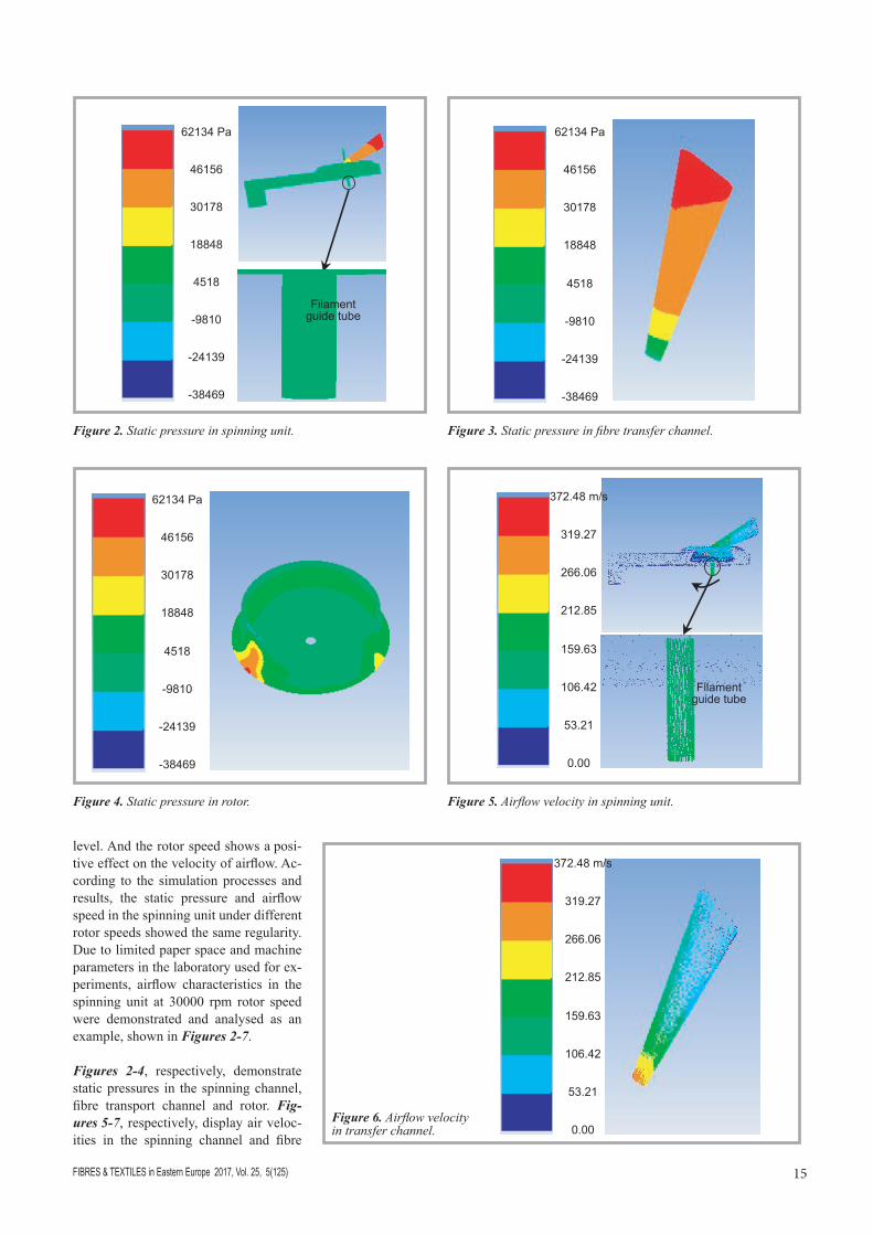
Figure 2. Static pressure in spinning unit. Figure 3. Static pressure in fibre transfer channel.
Figure 4. Static pressure in rotor. Figure 5. Airflow velocity in spinning unit.
Filament guide tube
1
372.48 m/s
319.27
266.06
212.85
159.63
106.42
53.21
0.00Figure 6. Airflow velocity in transfer channel.
level. And the rotor speed shows a posi-tive effect on the velocity of airflow. Ac-cording to the simulation processes and results, the static pressure and airflow speed in the spinning unit under different rotor speeds showed the same regularity. Due to limited paper space and machine parameters in the laboratory used for ex-periments, airflow characteristics in the spinning unit at 30000 rpm rotor speed were demonstrated and analysed as an example, shown in Figures 2-7.
Figures 2-4, respectively, demonstrate static pressures in the spinning channel, fibre transport channel and rotor. Fig-ures 5-7, respectively, display air veloc-ities in the spinning channel and fibre

FIBRES & TEXTILES in Eastern Europe 2017, Vol. 25, 5(125)16
of the high pressure area at the border of the exit of the fibre transport channel and sliding surface of the rotor, which is around 18848 Pa as of the shock wave of the airflow.
From Figures 5 and 6 it can be seen that the velocity in the filament guide tube is around 159.63 m/s, and does not change much along the tube, which is beneficial to the smooth movement of the filament to the rotor and twisting with staple fibre combined as composite yarn.
As the cross-sectional area of the fibre transport channel decreases, the airflow accelerates in the pipeline and reach-es the speed of 372.48 m/s at the exit. The speed acceleration of the airflow is not only beneficial to the extension of the hooked fibre in the channel, but also con-ducive to staple fibre in the rotor com-bined as yarn and then wrapped into fil-ament which smoothly forms composite yarn. The velocity of air flow in the rotor is closely related to that of air flow in the channel, which depends on the rotation speed of the rotor.
Figure 7 shows that as the air flow rushed out from the exit of the fibre transport channel into the rotor and im-pacts the wall of the rotor, it is divided into two streams moving in opposite directions, clockwise airflow and coun-ter-clockwise airflow into the rotor (po-sition 0), with high-speed rotation of the rotor, and then these two streams meet at the bottom position in the rotor (position 1), then, respectively, move along the edge of the filament guide tube in a cir-cular motion, meet again at location 2, converge into one stream, and the con-verged airflow continues to move toward in the groove along the rotation direction of the rotor.
Figure 7. Airflow velocity in rotor.
1
372.48
319.27
266.06
212.85
159.63
106.42
53.21
0.00
Filament guide tube
To 2
2
2
10
0
1
Figure 8. Strength of rotor spun composite yarn. Figure 9. Performance of rotor spun composite yarn.
Figure 8. Strength of rotor spun composite yarn.
Figure 9. Performance of rotor spun composite yarn.
As spinning parameters are limited in the laboratory, composite yarns can only be
spun at 30000 rpm of the rotor. Thus yarns were spun at 20000, 25000 and 30000 rpm
of the rotor. Figures 8-9 are the strength, breaking elongation, hairiness and CV of the
rotor spun composite yarn.
Table 2 shows the pressure and velocity distribution of airflow at different rotor
speeds. When the rotor speed was increased from 20000 rpm to 30000 rpm, the speed
of airflow in the spinning unit increased from 356 rpm to 372 rpm, while negative
pressure decreased from -4716 Pa to -5271 Pa. According to the Bernoulli Effect,
when the flow velocity of the fluid is larger, the pressure on the surface of the body in
contact with the fluid will be smaller, and when the flow velocity is smaller, the
pressure will be bigger. Combined with Table 2, it can be seen that at a bigger rotor
speed, the air velocity is larger, and the breaking strength of the composite yarn is
stronger. As the air flow velocity increases, the centrifugal force of the fibres in the
rotor increases, which means the cohesion of the fibres is stronger, making a tight
structure of the composite yarns, and hence friction between fibres is larger, which is
valuable to the breaking strength.
At the same time, as the air flow velocity increases, the tension and centrifugal
force of fibres are enhanced, with the original curving points of the fibre gradually
straightened, the yarn structure more compacted, and the yarn diameter becoming
thinner and the volume smaller, as a result of which the breaking elongation is
decreased. This is in agreement with the results in Figure 9, where the regulation of
yarn breaking elongation with rotor speed is when the rotor speed is higher, the
airflow velocity is faster and the elongation at break lower.
Figure 8. Strength of rotor spun
composite yarn. Figure 9. Performance of rotor spun
composite yarn.
As spinning parameters are limited in the laboratory, composite yarns can only be
spun at 30000 rpm of the rotor. Thus yarns were spun at 20000, 25000 and 30000 rpm
of the rotor. Figures 8-9 are the strength, breaking elongation, hairiness and CV of the
rotor spun composite yarn.
Table 2 shows the pressure and velocity distribution of airflow at different rotor
speeds. When the rotor speed was increased from 20000 rpm to 30000 rpm, the speed
of airflow in the spinning unit increased from 356 rpm to 372 rpm, while negative
pressure decreased from -4716 Pa to -5271 Pa. According to the Bernoulli Effect,
when the flow velocity of the fluid is larger, the pressure on the surface of the body in
contact with the fluid will be smaller, and when the flow velocity is smaller, the
pressure will be bigger. Combined with Table 2, it can be seen that at a bigger rotor
speed, the air velocity is larger, and the breaking strength of the composite yarn is
stronger. As the air flow velocity increases, the centrifugal force of the fibres in the
rotor increases, which means the cohesion of the fibres is stronger, making a tight
structure of the composite yarns, and hence friction between fibres is larger, which is
valuable to the breaking strength.
At the same time, as the air flow velocity increases, the tension and centrifugal
force of fibres are enhanced, with the original curving points of the fibre gradually
straightened, the yarn structure more compacted, and the yarn diameter becoming
thinner and the volume smaller, as a result of which the breaking elongation is
decreased. This is in agreement with the results in Figure 9, where the regulation of
yarn breaking elongation with rotor speed is when the rotor speed is higher, the
airflow velocity is faster and the elongation at break lower.
800
780
760
740
720
700
680
66020000 25000 30000
Rotort speed, rpm
Strength, cN14
12
10
8
6
4
2
020000 25000 30000
Rotort speed, rpm
CV
Breaking elongation, %Hairiness, S3
transport channel as well as the rotor speed.
It can be seen from Figure 2 that the negative pressure within the filament guide tube is around -9810 Pa. From Figure 3, it can be seen that the max-imum pressure is at the entrance of the fibre transport channel. With the process of fibre transport, the static pressure be-
comes negative; the outlet static pres-sure value is the smallest, going down to -9810 Pa. Negative pressure in the fibre transport channel makes the staple fibre move away from the opening roller and transfer to the rotor, which facilitates the filament combing and twisting with sta-ple fibre in the rotor. Figure 4 shows that most of the static pressure in the rotor is around -9810 Pa, and there is a small part

17FIBRES & TEXTILES in Eastern Europe 2017, Vol. 25, 5(125)
Experiments resultsAs spinning parameters are limited in the laboratory, composite yarns can only be spun at 30000 rpm of the rotor. Thus yarns were spun at 20000, 25000 and 30000 rpm of the rotor. Figures 8-9 are the strength, breaking elongation, hairi-ness and CV of the rotor spun composite yarn.
Table 2 shows the pressure and velocity distribution of airflow at different rotor speeds. When the rotor speed was in-creased from 20000 rpm to 30000 rpm, the speed of airflow in the spinning unit increased from 356 to 372 rpm, while neg-ative pressure decreased from -4716 Pa to -5271 Pa. According to the Bernoulli Effect, when the flow velocity of the flu-id is larger, the pressure on the surface of the body in contact with the fluid will be smaller, and when the flow velocity is smaller, the pressure will be bigger. Combined with Table 2, it can be seen that at a bigger rotor speed, the air veloc-ity is larger, and the breaking strength of the composite yarn is stronger. As the air flow velocity increases, the centrifugal force of the fibres in the rotor increases, which means the cohesion of the fibres is stronger, making a tight structure of the composite yarns, and hence friction be-tween fibres is larger, which is valuable to the breaking strength.
At the same time, as the air flow veloc-ity increases, the tension and centrifu-gal force of fibres are enhanced, with the original curving points of the fibre gradually straightened, the yarn structure more compacted, and the yarn diameter becoming thinner and the volume small-er, as a result of which the breaking elon-gation is decreased. This is in agreement with the results in Figure 9, where the regulation of yarn breaking elongation with rotor speed is when the rotor speed is higher, the airflow velocity is faster and the elongation at break lower.
Figure 9 also shows the distribution of hairiness at different rotor speeds. It can be seen from Table 2 and Figure 9 that as the rotation speed increases, the air-flow speed increases, which leads to yarn tension increases, as a result of which the tightness of the composite yarn in-creases and the entangled fibre increases, which conceals the hairiness of the yarn surface. And the wrapping effect of the filament on the staple fibre makes the original fluffy staple fibre and filament twisted with strong effect, with the fila-
ment closely wrapped together, thereby reducing parts of the hairiness.
The distribution of yarn unevenness (CV) under different rotor speeds is also demonstrated in Figure 9. Table 1 shows that with the same yarn density and twist factor, when the carding roll-er speed is constant, a higher rotor speed means more fibres fed into the rotor and a higher yarn delivering speed, which would weaken the opening effects of the opening carding roller. When combined with increased rotor air velocity and the influence of the air vortex, the fibres in the cup form more irregular fibres, and impurities and dust in the groove also increase, which eventually lead to an in-crease in composite yarn irregularity.
Conslusions1) Static pressure within the spinning
unit goes down to -7 kPa during the spinning processes, and especially the pressures of the filament guide tube, transport channel and rotor are all around this value.
2) The airflow speed accelerates in the tapered fibre transport channel, and the velocity at the outlet reach-es 392 m/s. As soon as the airflow at the exit of the fibre transport channel collides with the rotor slip surface, it is divided into two opposite direction airflows in a circular motion, reaches a certain location, then two combine as one flow after the cycled certain circles along the rotor, and continues moving towards and in the groove.
3) As the rotor speed increases, the air-flow velocity as well as the breaking strength and CV of the composite yarn increase, and the static pressure break-ing elongation and hairiness decrease.
This study gives light to understanding how fibre strands and filament travel and twist as composite yarn in the rotor, which can be used to optimise spinning parameters during spinning and design-ing a new rotor type.
AcknowledgementsThis work was supported by the National Natural Science Foundation of China No. 51403085 Fundamental Research Funds for the Central Universities No. JUSRP51631A, the Innovation Fund Project of Cooperation among Industries, Universities & Research Institutes of Jiangsu Province (BY2016022-29), and the Priority Academic Program Development of Jiangsu Higher Education Institutions (PAPD).
References 1.Alamdar-Yazdi A, Heppler GR. Abrasion
behavior of yarns at right angle for ring and rotor spun yarn [J]. Fibers & Textiles in Eastern Europe 2012; 20, 6(95): 54-57.
2.Chattopadhyay R, Tyagi GK, Goyal A. Studies of the hybrid effect in mechani-cal properties of tencel blended ring-, ro-tor- and air-jet spun yarns[J]. J Tex Inst 2013; 104(3): 339-349.
3. Jackowska-Strumillo L, Cyniak D, Cze -kalski J, Jackowski T. Quality of cotton yarns spun using ring-, compact-, and rotor-spinning machines as a function of selected spinning process parame-ters. Fibers & Textiles in Eastern Europe 2007; 15, 1(60): 24-30.
4.Roudbari BY, Eskandarnejad S, Moghadam MB. Effect of an increase in opening roller width on quality of rotor spun yarn. J Tex I 2016; 107(7): 864-872.
5.Esfahani RT, Shanbeh M. Effect of naf-vel and rotor type on physical and me-chanical properties of viscose rotor spun yarns. Fibers & Textiles in Eastern Eui-rope 2014; 22, 3(105): 61-65.
6.Hasani H, Semnani D, Tabatabaei S. Determining the optimum spinning con-ditions to produce the rotor yarns from cotton wastes. Ind Textila, 2010; 61(6): 259-264.
7.Etrati SM, Najar SS, Namiranian R. Investigation of the physical and men-chanical properties of polyester/visa-cose-elastic composite rotor-spun yarn. Fibers & Textiles in Eastern Europe 2011; 19(6): 28-33.
8.Nield R, ARA Ali. Open-end-spun core-spun yams. J Text Inst, 1977, 68(7): 223-229.
9.Cheng KB, Murray R. Effects of spinning conditions on structure and properties of open-end cover-spun yarns. Text Res J 2000; 70(8): 690-695.
10. Zhang H, Xue Y, Wang S.Effct of l-ament over-feed ratio on surface struc-ture of rotor-spun composite yarns. Text Res J 2006; 76(12): 922-927.
11. Pouresfandiari F, Fushimi S, Sakaguchi A, Saito H, Toriumi K, Nishimatsu T, Shi-mizu Y, Shirai H, Matsumoto Y, Gong H, Spinning conditions and characteristics of open-end rotor spun hybrid yarns. Text Res J 2002; 72(1): 61-70.
12. Yang RH, Wang SY. A mathematical model for rotor-spun composite yarn spinning process. Text Res J 2010; 80(6): 487-490
13. Kong LX, Platfoot RA. Two-dimension-al simulatio of air flow i th trasfrchannel of open-end rotor spinning ma-chines. Text Res J 1996; 66(10): 641-650.
14. Launder BE. Spalding DB. Lectures in Mathematical Models of Turbulence. London: Academic Press, 1972, p. 55
Received 5.12.2016 Reviewed 10.07.2017