“ruffled border” formation on a cap-free substrate: a ... · prabhas v. moghe3 ... transparency...
TRANSCRIPT
Journal of Materials Science: Materials in Medicine (2018) 29:38https://doi.org/10.1007/s10856-018-6046-4
TISSUE ENGINEERING CONSTRUCTS AND CELL SUBSTRATES
Original Research
“Ruffled border” formation on a CaP-free substrate: A first steptowards osteoclast-recruiting bone-grafts materials able to re-establish bone turn-over
Antonio Merolli1,2 ● Stephanie Fung1● N. Sanjeeva Murthy1 ● E. Thomas Pashuck1 ● Yong Mao1
● Xiaohuan Wu1●
Joseph A. M. Steele1 ● Daniel Martin3● Prabhas V. Moghe3 ● Timothy Bromage4 ● Joachim Kohn 1
Received: 18 January 2018 / Accepted: 5 March 2018 / Published online: 21 March 2018© The Author(s) 2018. This article is an open access publication
AbstractOsteoclasts are large multinucleated giant cells that actively resorb bone during the physiological bone turnover (BTO),which is the continuous cycle of bone resorption (by osteoclasts) followed by new bone formation (by osteoblasts).Osteoclasts secrete chemotactic signals to recruit cells for regeneration of vasculature and bone. We hypothesize that abiomaterial that attracts osteoclasts and re-establishes BTO will induce a better healing response than currently used bonegraft materials. While the majority of bone regeneration efforts have focused on maximizing bone deposition, the novelty inthis approach is the focus on stimulating osteoclastic resorption as the starter for BTO and its concurrent new vascularizedbone formation. A biodegradable tyrosine-derived polycarbonate, E1001(1k), was chosen as the polymer base due to itsability to support bone regeneration in vivo. The polymer was functionalized with a RGD peptide or collagen I, or blendedwith β-tricalcium phosphate. Osteoclast attachment and early stages of active resorption were observed on all substrates. Thetransparency of E1001(1k) in combination with high resolution confocal imaging enabled visualization of morphologicalfeatures of osteoclast activation such as the formation of the “actin ring” and the “ruffled border”, which previously requireddestructive forms of imaging such as transmission electron microscopy. The significance of these results is twofold: (1)E1001(1k) is suitable for osteoclast attachment and supports osteoclast maturation, making it a base polymer that can befurther modified to optimize stimulation of BTO and (2) the transparency of this polymer makes it a suitable analytical toolfor studying osteoclast behavior.
These authors contributed equally as “first author”: Antonio Merolli,Stephanie Fung.
* Joachim [email protected]
1 New Jersey Center for Biomaterials, Rutgers – The StateUniversity of New Jersey, New Brunswick, NJ 08901, USA
2 Universita Cattolica del Sacro Cuore, Clinica Ortopedica,Rome, Italy
3 High Resolution Microscopy, Biomedical Engineering, Rutgers –The State University of New Jersey, New Brunswick, NJ 08901,USA
4 Hard Tissue Research Unit. Department of Biomaterials andBiomimetics, New York University College of Dentistry,New York, NY 10010, USA
1234
5678
90();,:
1234567890();,:
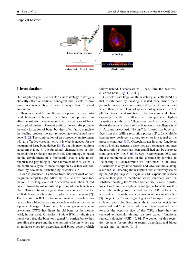
Graphical Abstract
1 Introduction
Our long-term goal is to develop a new strategy to design aclinically-effective artificial bone-graft that is able to pro-mote bone regeneration in cases of major bone loss andnon-union.
There is a need for an alternative option to current arti-ficial bone-grafts because they have not provided aneffective solution despite more than two decades of basicand applied research. Current artificial bone-grafts promotethe early formation of bone, but they often fail to completethe healing process towards remodeling vascularized newbone [1, 2]. The combination of an osteogenic environmentwith an effective vascular network is what is needed for thetreatment of large bone defects [3, 4], but this may require aparadigm change in the functional characteristics of bio-materials for artificial bone graft [3]. Our strategy is basedon the development of a biomaterial that is able to re-establish the physiological bone turnover (BTO), which isthe continuous cycle of bone resorption by osteoclasts fol-lowed by new bone formation by osteoblasts [5].
Bone is produced in embryo from mesenchymal or car-tilaginous templates [6]. After this first de novo bone for-mation, a lifelong cycle of osteoclastic resorption of oldbone followed by osteoblastic deposition of new bone takesplace. This continuous regenerative cycle is such that theadult skeleton may be entirely replaced every ten years [2].The first step in BTO is the recruitment of osteoclast pre-cursors from blood-stream mononuclear cells of the hema-topoietic lineage. These cells fuse to generate matureosteoclasts (OSC) that digest the old bone (or the bioma-terial, in our case). Osteoclasts initiate BTO by digging atrench (in trabecular bone) or a tunnel (in cortical bone) thusproviding the space and the chemotrophic factors which actas guidance clues for osteoblasts and blood vessels which
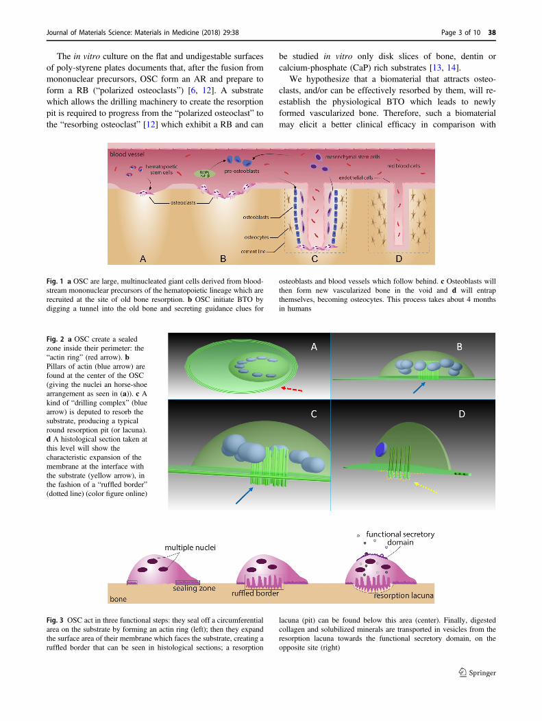
follow behind. Osteoblasts will, then, form the new vas-cularized bone (Fig. 1) [6–11].
Osteoclasts are large, multinucleated giant cells (MNGC)that resorb bone by creating a sealed zone inside theirperimeter where a circumscribed drop in pH occurs andwhere there is the release of specific collagenases. The lowpH facilitates the dissolution of the bone mineral phase,exposing slender needle-shaped undigestable hydro-xyapatite crystals [9]. Collagenases, such as cathepsin K,digest the organic phase of the bone (mostly collagen typeI). A round osteoclastic “lacuna” (pit) results on bone sur-face from this drilling resorption process (Fig. 2). Multiplelacunae may coalesce in a long trench or in a tunnel as theprocess continues [10]. Osteoclasts act in three functionalsteps which are generally described as a sequence, but oncethe resorption process has been established can be observedsimultaneously (Fig. 3) [6, 8]. Step 1: attachment. OSC sealoff a circumferential area on the substrate by forming an“actin ring” (AR); resorption will take place in this area.Attachment is a dynamic process and OSC can move alonga surface, still keeping the resorption area effectively sealedby the AR [8]. Step 2: resorption. OSC expand the surfacearea of their part of membrane which interfaces with thesubstrate, creating the “ruffled border” (RB) seen in histo-logical sections; a resorption lacuna (pit) is found below thisarea. The sealing zone defined by the AR protects theadjacent cells from the acidic environment present at the RB[8]. Step 3: vesicular trafficking. OSC transport digestedcollagen and solubilized minerals in vesicles which areprocessed and “transcytosised” from the resorption lacunatowards the opposite side of the OSC, where they aresecreted extracellular through an area called “functionalsecretory domain” (FSD) [6, 9]. The content of this secre-tion contains factors able to recruit osteoblasts and bloodvessels into the tunnel [6, 11].
38 Page 2 of 10 Journal of Materials Science: Materials in Medicine (2018) 29:38
The in vitro culture on the flat and undigestable surfacesof poly-styrene plates documents that, after the fusion frommononuclear precursors, OSC form an AR and prepare toform a RB (“polarized osteoclasts”) [6, 12]. A substratewhich allows the drilling machinery to create the resorptionpit is required to progress from the “polarized osteoclast” tothe “resorbing osteoclast” [12] which exhibit a RB and can
be studied in vitro only disk slices of bone, dentin orcalcium-phosphate (CaP) rich substrates [13, 14].
We hypothesize that a biomaterial that attracts osteo-clasts, and/or can be effectively resorbed by them, will re-establish the physiological BTO which leads to newlyformed vascularized bone. Therefore, such a biomaterialmay elicit a better clinical efficacy in comparison with
Fig. 2 a OSC create a sealedzone inside their perimeter: the“actin ring” (red arrow). bPillars of actin (blue arrow) arefound at the center of the OSC(giving the nuclei an horse-shoearrangement as seen in (a)). c Akind of “drilling complex” (bluearrow) is deputed to resorb thesubstrate, producing a typicalround resorption pit (or lacuna).d A histological section taken atthis level will show thecharacteristic expansion of themembrane at the interface withthe substrate (yellow arrow), inthe fashion of a “ruffled border”(dotted line) (color figure online)
Fig. 3 OSC act in three functional steps: they seal off a circumferentialarea on the substrate by forming an actin ring (left); then they expandthe surface area of their membrane which faces the substrate, creating aruffled border that can be seen in histological sections; a resorption
lacuna (pit) can be found below this area (center). Finally, digestedcollagen and solubilized minerals are transported in vesicles from theresorption lacuna towards the functional secretory domain, on theopposite site (right)
Fig. 1 a OSC are large, multinucleated giant cells derived from blood-stream mononuclear precursors of the hematopoietic lineage which arerecruited at the site of old bone resorption. b OSC initiate BTO bydigging a tunnel into the old bone and secreting guidance clues for
osteoblasts and blood vessels which follow behind. c Osteoblasts willthen form new vascularized bone in the void and d will entrapthemselves, becoming osteocytes. This process takes about 4 monthsin humans
Journal of Materials Science: Materials in Medicine (2018) 29:38 Page 3 of 10 38

current bone graft materials as they rarely achieve the newvascularization and complete filling of the bone loss. Ourultimate clinical goal is the complete replacement of thenew bone graft material by fully vascularized endogenousbone.
In this first study, we have been able to demonstrate howthe early two steps in osteoclast activity, namely the for-mation of the “actin ring” and the formation of the “ruffledborder”, can occur by using the CaP-free tyrosine-derivedpolycarbonate (E1001(1k)). E1001(1k) has shown promisein vivo where the polymer-bone interface exhibited mor-phological signs of integration and remodeling [15, 16]. Weinvestigated the ability of E1001(1k) to support osteoclastrecruitment and activation in vitro, alone or in blends withRGD polypeptide, collagen type I and β-TCP (beta-tri-calcium phosphate), factors involved in steps 1, 2 and 3respectively. Cultures on hydroxyapatite and on polystyreneserved as controls. The formation of the RB was visualizedby immunofluorescent staining and confocal microscopy.
We are aware that an in vitro evaluation has intrinsiclimitations to incorporate all of the factors that affect cellbehavior in vivo. However, in vitro methods may allow thestudy of the very early events in osteoclast activity, namelythe “actin ring” and the “ruffled border” formation, in aneasy-to-access and reproducible way. So, we see the in vitroanalysis of osteoclast behavior as a necessary first step inthe development of a future BTO-promoting, osteoclast-recruiting material.
2 Materials and methods
2.1 Experimental design
2.1.1 Selection and differentiation of OSC on polystyrene
To test our ability to obtain well-defined OSCs we estab-lished protocols to select macrophages from the bonemarrow aspirate of the Sprague-Dawley rat by optimizingpublished protocols [17]. These macrophages were thenstimulated to fuse into MNGC, which possess the mor-phological characteristics of osteoclasts (like a periphery offilopodia, a circular or horse-shoe arrangement of nuclei,etc.). We used the anti-RANK (receptor activator of nuclearfactor-kappaB) antibody to mark specifically our MNGC as“osteoclasts”.
2.1.2 Attachment of OSC on different substrates
To test our ability to culture OSC on different substrates weseeded OSC on standard polystyrene plates, a substrate thatthey cannot digest. Then we seeded OSC on 1 mm thickhydroxyapatite discs (a standard artificial substrate to
culture OSC, alternative to natural bone or dentin). Finally,we seeded OSC on the candidate polymer E1001(1k), aloneor in three blends with RGD peptide, collagen type I and β-TCP.
2.1.3 Imaging of the “actin ring” and the “ruffled border”
To test the possibility to detect and visualize the earlyphases of OSC activity (namely AR and RB formation) withlight transmitted through the substrate we used invertedfluorescence microscopy and laser confocal microscopy.
Transmitted light microscopy is an unusual modality inimaging OSC culture as bone, dentin or CaP-rich substrateshave a degree of opacity. However, it can provide a directvisualization of the OSC-substrate interface.
2.2 Substrate preparation
Solvent casting was used to prepare films of E1001(1k)alone and in combination with RGD, collagen type I and β-TCP. Before that, samples of E1001(1k) alone and E1001(1k) in combination with RGD were also prepared by spin-coating the polymer solutions onto glass coverslips. Solventcasting was adopted as a technique of choice after it wasdemonstrated that spin-coating will enable OSC attachmentbut will not produce films thick enough to be resorbed byOSC.
2.2.1 Spin coating technique
A 2% (w/v) solution of the polymer was prepared in 1:1mixture of dichloromethane (DCM) and tetrahydrofuran(THF). The samples were spin coated under dry condition(8% RH) on a Headway Research Inc. (Garland, TX) spincoater. About 70 microliters of solution was placed on eachcover slip, and spin coated at 3000 rpm for 30 s. Thethickness of the film, as estimated from similar samplesusing quartz crystal microbalance, was ~100 nm.
2.2.2 Solvent casting technique
E1001(1k), RGD-modified E1001(1k), and E1001(1k)+collagen type I films were prepared by dissolving 200 mg ofthe polymer in a 5 mL DCM. E1001(1k)-β-TCP was pre-pared by dissolving 127.5 mg of E1001(1k) in 5 ml ofDCM. Films were cut into circles of 10 mm in diameterusing a biopsy punch. Cut films fit into the bottom of 48-well tissue culture plates and had a thickness of about 25–45microns.
2.2.2.1 RGD-modified E1001(1k) The modified polymerwas obtained by coupling RGD to E1001(1k) using amaleimide reaction with cysteine on the peptide sequence,
38 Page 4 of 10 Journal of Materials Science: Materials in Medicine (2018) 29:38
produced by solid phase peptide synthesis and purifiedby HPLC. A GRGDSP peptide was synthesized usingsolid phase peptide synthesis. All amide couplings weredone using O-(6-Chlorobenzotriazol-1-yl)-N,N,N′,N′-tetra-methyluronium hexafluorophosphate (HCTU), unlessotherwise noted. For each coupling the amino acid, HCTUand diisopropylethylamine (DIPEA) were added in a 4:4:6ratio to peptide. After successful coupling the Fmoc groupwas removed by washing the resin with 20% piperidine indimethylformamide (DMF) twice for 5 min. A ninhydrintest was performed to check for a positive result. For theback bone peptide the N-terminus was capped upon com-pletion of the amino acid couplings. The peptide was thencleaved from the resin in 95% trifluouroacetic acid (TFA)(Sigma-Aldrich) and 2.5% triisopropylsilane (TIS). Thecleavage solution was emptied into a round bottomed flaskand washed 2 × with dichloromethane (DCM). The solutionwas removed using rotary evaporation, and then the productwas precipitated in diethyl ether. This molecule wasthen dried under vacuum and dissolved in water. It waspurified by high pressure liquid chromatography (HPLC)under acidic conditions. A gradient was run from 95%water/20% acetonitrile to 95% ACN/5% water with 0.1%TFA at 10 mLs/minute. Upon purification, the acetonitrilewas removed through rotary evaporation, the solution wasfrozen and ice removed with lyophilization. 320 mgof E1001(1k) was dissolved into 10 mLs of DMSO andactivated with 33.6 mg of HCTU and 22.4 mg of DIPEAin a round bottomed flask. After 5 min of activation 50 mgof the GRGDSP peptide was added to the mixture and itwas stirred overnight. The next day the solution was pre-cipitated in isopropanol, dissolved in DCM and reprecipi-tated in isopropanol. The polymer-peptide conjugate wasplaced under vacuum and conjugation was quantified usingNMR.
2.2.2.2 E1001(1k)-collagen type I The modified polymerwas prepared by placing an E1001(1k) film in MES buffer(pH 4.5) and 50 milligrams of N-(3-Dimethylaminopropyl)-N′-ethylcarbodiimide hydrochloride (EDC) with 25 mg ofN-Hydroxysuccinimide (NHS) for 5 min. The sheet wasremoved from the MES solution after 5 min, washed brieflywith the MES solution, and then added to a fresh solution ofMES buffer with 10 mg of collagen. The collagen wasreacted with the film over night, after which it was washed3× with PBS and then dried under vacuum.
2.2.2.3 E1001(1k)-β-TCP Composite polymer film wasprepared by blending 15 w/v% beta-TCP (BerkeleyAdvanced Biomaterials Inc, Berkeley CA) with a 25.5 w/v% solution of E1001(1k) in DCM. Films were cast in Teflondish and allowed to dry at a constant vapor pressure over-night and then dried under vacuum at 45 C for 18 h.
2.2.3 Sterilization
Films were sterilized by UV for 2 h; the UV lamp was aSylvania G36T5/SP Germicidal UV-C 39W FluorescentLamp emitting at 254 nm. The sterilized film was cut intodiscs of 10 mm in diameter to fit into the bottom of 48-welltissue culture plates.
2.3 Osteoclast culture
Bone marrow was isolated from the femurs of male SpragueDawley rats 8 weeks old. Femurs were flushed with sterilePBS using a 5 mL syringe and 25 G needle. Bone marrowwas collected in a 15 mL conical tube. Samples were pel-leted at 1400 RPM for 5 min, washed once in Dulbecco’sModified Eagle’s medium (DMEM), resuspended incryostorage media (90% FBS+ 10% DMSO) and stored inliquid nitrogen until use. Experiments were conducted intriplicate (n= 3). For the isolation and differentiation ofOSC, the vial of bone marrow was quick thawed at 37oC.The bone marrow was collected in complete DMEM (basalmedia+ 10% FBS+ 35 μg/mL gentamicin), pelleted toremove residual DMSO, and then resuspended in 10 mLcomplete DMEM containing 50 ng/mL M-CSF (Peprotech).Cells were plated onto one 10 cm tissue-culture plate. After72 h, the media was removed and the monolayer waswashed with ice cold PBS. This process selected a popu-lation of Macrophages from the bone marrow aspirate.Macrophages were lifted using a cell scraper, collected intoa tube containing complete media, and spun down at 1000RPM for 5 min. The pellet was resuspended in completemedia containing 50 ng/mL M-CSF, and the volume wassplit between two 10 cm tissue culture plates. After 48 h,media was changed to complete media containing 50 ng/mLM-CSF and 100 ng/mL RANKL (Peprotech). Cells werecultured for 4 days, with media changes every 48 h. After4 days of differentiation, mature osteoclasts were lifted fromthe plate using a cell scraper and seeded onto the varioussubstrates. Cells were cultured in complete media contain-ing 50 ng/mL M-CSF and 100 ng/mL RANKL and allowedto attach for 48 h. Samples were then washed once withPBS and fixed in 4% paraformaldehyde (PFA) for 10 min.
2.4 Osteoclasts imaging
2.4.1 Immunostaining
RANK was the chosen selective marker for OSC (seeDiscussion). Samples were permeabilized with 0.25%Triton-X for 15 min, then blocked in staining solution(4.3% FBS+ 1% BSA in 1 × HBSS) for 30 min. Sampleswere stained with primary antibody, anti-RANK (mousemonoclonal, Life Technologies, 1:100 dilution in staining
Journal of Materials Science: Materials in Medicine (2018) 29:38 Page 5 of 10 38
solution), overnight at 4oC. Samples were washed 3× withPBS, then incubated with the secondary antibody, goat anti-mouse 488 (Life Technologies, 1:250 dilution), and rho-damine phalloidin (Life Technologies, 1:500 dilution) instaining solution for 1 h at room temperature. Samples werewashed 3× in PBS, then incubated with Hoechst DNA stain(AnaSpec, Inc., 1:500 dilution) in PBS for 10 min at roomtemperature. Samples were washed 3× in PBS prior toimaging.
2.4.2 Fluorescence microscopy
Cells were imaged using an inverted DIC fluorescencemicroscope (Zeiss Axio Observer D1; Jena, Germany).Images were acquired using the DAPI filter (335–383excitation, 420–470 emission), Alexa 555 filter (538–562excitation, 570-40 emission), and GFP filter (450–490excitation, 500–550 emission) and an AxioCam MRmdigital camera. Images were analyzed using NIH ImageJsoftware.
2.4.3 Laser scanning confocal microscopy
Cells were imaged using an inverted laser scanning confocalmicroscope (Zeiss LSM 780; Jena, Germany). Images weretaken using a 63× objective lens (Zeiss, Numerical Aperture1.4). Images were acquired using a 405-nm laser for DAPI,and a 488-nm laser for Alexa-488, and a 594-nm laser for
Alexa-594. Confocal images series (i.e., z-stacks) weretaken at increments of 0.7 μm, and a 0.094 micron-to-pixelratio in lateral resolution. 3D projections of cells werecreated using Icy (v1.9.4.0, created by the QuantitativeImage Analysis Unit at Institut Pasteur), and by using theStereo 3D Canvas (VTK), which is free and in the publicdomain [18]. Deconvolution was done using the Zeiss ZenBlue software.
3 Results
3.1 Analysis of OSC on spin-coated substrates
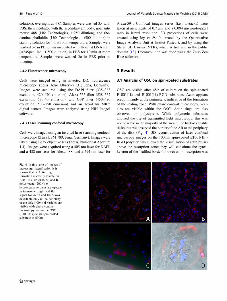
OSC are visible after 48 h of culture on the spin-coatedE1001(1k) and E1001(1k)-RGD substrates. Actin appearspredominantly at the perimeters, indicative of the formationof the sealing zone. With phase contrast microscopy, vesi-cles are visible within the OSC. Actin rings are alsoobserved on polystyrene. While polymeric substratesallowed the use of transmitted light microscopy, this wasnot possible in the majority of the area of the hydroxyapatitedisks, but we observed the border of the AR at the peripheryof the disk (Fig. 4). 3D reconstruction of laser confocalmicroscopy images on the 100 nm spin-coated E1001(1k)-RGD polymer film allowed the visualization of actin pillarsabove the resorption zone; they will constitute the cytos-keleton of the “ruffled border”; however, no resorption was
Fig. 4 In this serie of images ofincreasing magnification it isshown that: a Actin ringformation is clearly visible onE1001(1k)-RGD (50×) and bpolystyrene (200×); chydroxyapatite disks are opaquein transmitted light and thesignal for Actin and DNA wasdetectable only at the peripheryof the disk (400×); d vesicles arevisible with phase contrastmicroscopy within the OSC(E1001(1k)-RGD spin-coatedsubstrate at 630×)
38 Page 6 of 10 Journal of Materials Science: Materials in Medicine (2018) 29:38

possible on this thin substrate (Fig. 5). Orthogonal 3Dreconstructed sections centered in the resorption area giveviews of the dome-shape distribution of nuclei. 3D visua-lization of nuclei alone shows how the typical horseshoearrangement seen close to the substrate provides the spaceto accommodate the actin pillars of the RB (Fig. 6).Transparency of the substrate allowed for the visualizationof “channels” that connect the resorption zone to thefunctional secretory domain (Fig. 7). At our stage ofresearch it is not possible to consider them as an evidencefor the functional “step 3” in OSC activity because nomarker was used to detect transcytosed vesicles.
3.2 Analysis of OSC on solvent-casted substrates
Thicker solvent-casted films provided a substrate that can beresorbed. The transparency of the solvent-casted E1001(1k)alone film enabled high resolution imaging. The incor-poration of RGD and collagen I into the polymer filmdecreased the degree of light transmittance through the film,
Fig. 5 a A “maximum intensity projection” gives the reconstruction ofmultiple transverse confocal sections of an OSC cultured on a spin-coated E1001(1k)-RGD substrate. A high resolution was obtainedthanks to the transparency of the substrate. (scale bar= 50 μm) b
Orthogonal 3D reconstructions centered in the resorption area giveviews of the dome-shape distribution of nuclei (the blue line indicatesthe level of the section) (color figure online)
Fig. 6 a 3D reconstructionvisualizes the dome-shapeddistribution of nuclei and b thepresence of actin pillars in theresorption zone (yellow arrows).Maximum intensity projectionof isolated nuclei (MIP) andtransverse sections taken at threedifferent heights from thesubstrate, show how thehorseshoe arrangement providesspace for the actin pillars of theRB (color figure online)
Fig. 7 Transparency of the thin spin-coated polymeric substrateallowed the visualization of “channels” that connect the resorptionzone to the functional secretory domain (white arrows) (color figureonline)
Journal of Materials Science: Materials in Medicine (2018) 29:38 Page 7 of 10 38

thus reducing the image resolution. Imaging of the E1001(1k)/CaP substrate was even more difficult due to theautofluorescence of the large calcium phosphate crystalsembedded in the substrate. However, AR formation wasdocumented on all the substrates. E1001(1k) showed thehighest number of cells with typical morphological char-acterstics of osteoclasts, like a periphery of filopodia and acircular or horseshoe arrangement of nuclei around the“drilling complex”. 3D reconstruction and orthogonal sec-tions showed that the actin fluorescence signal can bedetected into the surface of the substrate, but only below thedrilling complex. Since the quality of imaging varied fromsubstrate to substrate, the best resolution was obtained withthe full transparent E1001(1k). For this reason, E1001(1k)allowed the repeated visualization of a structured borderbelow the drilling complex which presents the morpholo-gical characters of the “ruffled border” membrane (Fig. 8).
4 Discussion
The idea to have osteoclasts (osteo-c-lasts) to resorb thebone graft material and to direct new bone formation andvascularization is based on the principles of bone biology.At the same time, this idea is a leap forward in a researchfield which has focused, in the past three decades, mostly onsupporting osteoblasts (osteo-b-lasts) and on inducing boneformation, without recognizing the role of osteoclasts andthe importance of bone formation obtained following boneresorption [19]. In a similar approach, the promotion ofosteoclastogenesis and angiogenesis has been attempted tointegrate and remodel bone allografts [20–23]. A clinically-effective bone graft material able to address major bone losswill be regarded as a real clinical advancement. Currentmaterials (often called “artificial bone substitutes”) promotethe early formation of bone, but fail to complete the healingprocess in large defects [1, 2]. The inability to achieve the“macroscopic bone remodeling” (the process by which bonerestructures continuously to respond to external mechanicalloads [24]) may be due to a failure to re-establish the“microscopic bone turnover”.
The introduction of “artificial bone substitutes” in clin-ical use generated great expectations in surgeons whosegoal was to overcome the limitations of autografts(demanding surgical technique; limited availability; donor-site morbidity) and of allografts (inability to achieve a fullintegration with host bone; variability in the quality of bonebecause of factors associated with the donor) [25]. In mostcases, bone formation is limited in space and time [20, 26].Quite interestingly to us, allografts and non-vascularizedautografts may not elicit an adequate healing response ifbone remodeling is limited and new blood vessels do notextend the host’s vascular network into the graft [25]. From
Fig. 8 a E1001(1k)-TCP imaging was difficult due to the auto-fluorescence of the calcium phosphate crystals embedded in the sub-strate, however this clearly helps in visualizing the substrate itself (the“blue” region in the orthogonal sections). b E1001(1k)-RGD and cE1001(1k)-collagen have a diminished light transmittance through thefilm, but the actin signal is seen deeper into the substrate below the“drilling complex” region. d E1001(1k) is fully transparent and pro-vided higher-definition images where a “ruffled border” interface withthe substrate was detectable. e An optical section in the “drillingcomplex” zone (* in d) shows a “ruffled border” profile of the actinpillars (yellow dotted line; the white line represents the substrateprofile; the blue line represent the confocal transverse section) (colorfigure online)
38 Page 8 of 10 Journal of Materials Science: Materials in Medicine (2018) 29:38
the material point of view this seems to be odd, as bothallografts and non-vascularized autografts have a compo-sition and structure that matches healthy bone in a far betterway than any engineered artificial bone substitute. Wespeculate that factors that trigger BTO may have been lostin dead allografts or in hypoxic non-vascularized autografts.Therefore, the understanding of the basic process and reg-ulation of BTO becomes critical to identify the key playersin bone regeneration.
The fact that the CaP-free E1001(1k) is a suitable substratefor osteoclast culture was an unexpected finding. CaP-freepolymer formulations, like poly-L-Lactic Acid (PLLA), havenot been shown to support OSC differentiation [27]. However,this makes E1001(1k) a promising candidate in the pursuit ofa biomaterial that recruits osteoclasts to re-establishes BTO.The creation of a less acidic environment, in comparison withmost of the clinically-used degradable biomaterials likePLLA, may be a clue for an OSC supporting material as OSCfunction will be limited in an acidic environment.
As we found that OSC can be cultured on all the E1001(1k) substrates, our attention was however quickly re-focused on E1001(1k) alone, because the unmodifiedpolymer has the advantage of being an easier-to-producematerial in comparison with its blends and because of itsbetter optical properties. Transparency is an additionalunexpected benefit of E1001(1k) and it allowed the visua-lization of key morphological features of osteoclasts (actinring, multiple nuclei, expression of RANK, ruffled border)by transmitted light (instead of reflected light). It alsoavoided the need to transversely cut the sample as it wouldbe required by transmission electron microscopy andfocused ion-beam dissection [28]. The quality in thevisualization of the interface between osteoclast and sub-strate and the avoidance of the destructive cut of the sample(both allowed by transmitted light) may promote a newin vitro modality in the study of osteoclasts behavior andtheir response to drugs supposed to regulate their activity.
The search for evidences of a possible transcytosisactivity is one of our future goals. It is known that thetranscytotic pathway is supported by thick bundles ofmicrotubules which span from the RB tyo the FSD [8].Theoretical speculation suggests that both collagen andneedle-shaped hydroxyapatite crystals should be incorpo-rated in the our polymer for transcytosis to occur; however,we would like to explore the role of the actin channelsevidenced in Fig. 7 when these components where notpresent into the substrate. Another future goal is the betterdifferentiation between true OSC and morphologicallysimilar MNGC (like those found in a foreign body reaction,for example). OSC themselves are a subset of MNGC, andwhile they share the same precursor cells, OSC reside spe-cifically in the vicinity of bone, whereas MNGC are found atpathological sites of inflammation and surfaces of foreign
bodies. OSC are capable of resorbing bone completely,whereas MNGC are only capable of dissolving the mineralphase. While both cell types are capable of forming an actinring, MNGC are unable to digest the matrix of the bone dueto the inhability to form a RB and to express cathepsin K[29]. Calcitonin receptor and RANK are considered as thespecific markers for OSC while MNGC exclusively expressCD86 and HLA-DR [30]. While in this study we havedemonstrated positive staining of RANK in our OSC, weplan to add specific MNGC markers as a control. Weadvocate that a similar procedure should be adopted in thestudy of OSC because the traditional OSC marker, the tar-trate resistant acid phosphatase (TRAP), can stain both typesof cells (even if affinity for OSC is greater [19]).
5 Conclusions
This is the first report of a high resolution imaging in visiblelight of the OSC “actin ring” and “ruffled border” formationon CaP-free polymeric bone graft material. The polymerE1001(1k) supports OSC in-vitro culture and its tranpar-ency allows the visualization of key morphological featureswithout the need to destructively cut the cell. This may leadto the development of an analytical method which mayprovide the same information as transmission electronmicroscopy but will not require the complex sample pre-paration prior to imaging. Furthermore, the sample willremain intact for subsequent analysis. We are aware thatthis initial study is just the very first step in a proposed newstrategy for bone grafting based on the recruitment of OSCto re-establish BTO and its concurrent new vascularizedbone formation. However, our initial results unveiled newpossibilities for the in-vitro study of OSC and this may bebeneficial in other applications as well.
Compliance with ethical standards
Conflict of interest The authors declare that they have no conflict ofinterest.
Open Access This article is distributed under the terms of the CreativeCommons Attribution 4.0 International License (http://creativecommons.org/licenses/by/4.0/), which permits unrestricted use,distribution, and reproduction in any medium, provided you giveappropriate credit to the original author(s) and the source, provide alink to the Creative Commons license, and indicate if changes weremade.
References
1. Kurien T, Pearson RG, Scammell BE. Bone graft substitutescurrently available in orthopaedic practice: the evidence for theiruse. Bone Jt J. 2013;95-B:583–97. https://doi.org/10.1302/0301-620X.95B5.30286.
Journal of Materials Science: Materials in Medicine (2018) 29:38 Page 9 of 10 38

2. Fillingham Y, Jacobs J. Bone grafts and their substitutes. Bone JtJ. 2016;98-B:6–9. https://doi.org/10.1302/0301-620X.98B.36350.
3. Kazemzadeh-Narbat M, Rouwkema J, Annabi N, Cheng H,Ghaderi M, Cha BH, Aparnathi M, Khalilpour A, Byambaa B,Jabbari E, Tamayol A, Khademhosseini A. Engineering photo-crosslinkable bicomponent hydrogel constructs for creating 3Dvascularized bone. Adv Healthc Mater. 2017;6. https://doi.org/10.1002/adhm.201601122.
4. Sivaraj KK, Adams RH. Blood vessel formation and function inbone. Development. 2016;143:2706–15. https://doi.org/10.1242/dev.136861.
5. Banse X, Devogelaer JP, Holmyard D, Grynpas M. Vertebralcancellous bone turn-over: microcallus and bridges in backscatterelectron microscopy. Micron. 2005;36:710–4.
6. Crockett JC, Rogers MJ, Coxon FP, Hocking LJ, Helfrich MH.Bone remodelling at a glance. J Cell Sci. 2011;124:991–8. https://doi.org/10.1242/jcs.063032.
7. Novack DV, Mbalaviele G. Osteoclasts-key players in skeletalhealth and disease. Microbiol Spectr. 2016;4. https://doi.org/10.1128/microbiolspec.MCHD-0011-2015.
8. Soysa NS, Alles N. Osteoclast function and bone-resorbingactivity: an overview. Biochem Biophys Res Commun.2016;476:115–20. https://doi.org/10.1016/j.bbrc.2016.05.019.
9. Wenisch S, Stahl JP, Horas U, Heiss C, Kilian O, Trinkaus K,Hild A, Schnettler R. In vivo mechanisms of hydroxyapatiteceramic degradation by osteoclasts: fine structural microscopy. JBiomed Mater Res A. 2003;67:713–8.
10. Merrild DM, Pirapaharan DC, Andreasen CM, Kjærsgaard-Andersen P, Møller AM, Ding M, Delaissé JM, Søe K. Pit- andtrench-forming osteoclasts: a distinction that matters. Bone Res.2015;3:15032 https://doi.org/10.1038/boneres.2015.32. Erratumin: Bone Res. 2016 22;4:16006.
11. Karsdal MA, Neutzsky-Wulff AV, Dziegiel MH, Christiansen C,Henriksen K. Osteoclasts secrete non-bone derived signals thatinduce bone formation. Biochem Biophys Res Commun.2008;366:483–8.
12. Segeletz S, Hoflack B. Proteomic approaches to study osteoclastbiology. Proteomics. 2016;16:2545–56. https://doi.org/10.1002/pmic.201500519.
13. Contractor T, Babiarz B, Kowalski AJ, Rittling SR, Sørensen ES,Denhardt DT. Osteoclasts resorb protein-free mineral (Osteologicdiscs) efficiently in the absence of osteopontin. Vivo.2005;19:335–41.
14. Zhang J, Sun L, Luo X, Barbieri D, de Bruijn JD, van BlitterswijkCA, Moroni L, Yuan H. Cells responding to surface structure ofcalcium phosphate ceramics for bone regeneration. J Tissue EngRegen Med. 2017;11:3273–83. https://doi.org/10.1002/term.2236.
15. Zhang W, Zhang Z, Chen S, Macri L, Kohn J, Yelick PC. Man-dibular jaw bone regeneration using human dental cell-seededtyrosine-derived polycarbonate scaffolds. Tissue Eng Part A.2016;22:985–93. https://doi.org/10.1089/ten.TEA.2016.0166.
16. Kim J, Magno MH, Ortiz O, McBride S, Darr A, Kohn J, Hol-linger JO. Next-generation resorbable polymer scaffolds withsurface-precipitated calcium phosphate coatings. Regen Biomater.2015;2:1–8. https://doi.org/10.1093/rb/rbu019.
17. Marino S, Logan JG, Mellis D, Capulli M. Generation and cultureof osteoclasts. Bone Rep. 2014;3:570. https://doi.org/10.1038/bonekey.2014.65.
18. De Chaumont F, Dallongeville S, Chenouard N, Hervé N, Pop S,Provoost T, Meas-Yedid V, Pankajakshan P, Lecomte T, LeMontagner Y. Icy: an open bioimage informatics platform forextended reproducible research. Nat Methods. 2012;9:690–96.
19. Pasuri J, Holopainen J, Kokkonen H, Persson M, Kauppinen K,Lehenkari P, Santala E, Ritala M, Tuukkanen J. Osteoclasts in theinterface with electrospun hydroxyapatite. Colloids Surf BBiointerfaces. 2015;135:774–83. https://doi.org/10.1016/j.colsurfb.2015.08.045.
20. Le Nihouannen D, Hacking SA, Gbureck U, Komarova SV,Barralet JE. The use of RANKL-coated brushite cement to sti-mulate bone remodelling. Biomaterials. 2008;29:3253–9. https://doi.org/10.1016/j.biomaterials.2008.03.035.
21. Ito H, Koefoed M, Tiyapatanaputi P, Gromov K, Goater JJ,Carmouche J, Zhang X, Rubery PT, Rabinowitz J, Samulski RJ,Nakamura T, Soballe K, O’Keefe RJ, Boyce BF, Schwarz EM.Remodeling of cortical bone allografts mediated by adherentrAAV-RANKL and VEGF gene therapy. Nat Med.2005;11:291–7.
22. Sharmin F, Adams D, Pensak M, Dukas A, Lieberman J, Khan Y.Biofunctionalizing devitalized bone allografts through polymer-mediated short and long term growth factor delivery. J BiomedMater Res A. 2015;103:2847–54. https://doi.org/10.1002/jbm.a.35435.
23. Sharmin F, McDermott C, Lieberman J, Sanjay A, Khan Y. Dualgrowth factor delivery from biofunctionalized allografts:Sequential VEGF and BMP-2 release to stimulate allograftremodeling. J Orthop Res. 2017; 35:1086–95. https://doi.org/10.1002/jor.23287.
24. Merolli A, Leali PT. Hard Tissue Structure and Functionality. In:Santin M, Phillips G, eds. Biomimetic, bioresponsive, andbioactive materials: An introduction to integrating materials withtissues. Hoboken, NJ, USA: John Wiley & Sons, Inc.; 2012.https://doi.org/10.1002/9781118129906.ch3.
25. Enneking WF, Campanacci DA. Retrieved human allografts: aclinicopathologicaln study. J Bone Jt Surg Am. 2001;83-A:971–86.
26. Cuckler JM. Bone loss in total knee arthroplasty: graft augmentand options. J Arthroplast. 2004;19:56–8.
27. Jones GL, Motta A, Marshall MJ, El Haj AJ, Cartmell SH.Osteoblast: osteoclast co-cultures on silk fibroin, chitosan andPLLA films. Biomaterials. 2009;30:5376–84. https://doi.org/10.1016/j.biomaterials.2009.07.028.
28. Diez-Escudero A, Espanol M, Montufar EB, Di Pompo G, Cia-petti G, Baldini N, Ginebra MP. Focus ion beam/scanning electronmicroscopy characterization of osteoclastic resorption of calciumphosphate substrates. Tissue Eng Part C Methods.2017;23:118–24. https://doi.org/10.1089/ten.TEC.2016.0361.
29. ten Harkel B, Schoenmaker T, Picavet DI, Davison NL, de VriesTJ, Everts V. The foreign body giant cell cannot resorb bone, butdissolves hydroxyapatite like osteoclasts. PLoS ONE. 2015;10:e0139564. https://doi.org/10.1371/journal.pone.0139564.
30. Miron RJ, Zohdi H, Fujioka-Kobayashi M, Bosshardt DD. Giantcells around bone biomaterials: osteoclasts or multi-nucleatedgiant cells? Acta Biomater. 2016;46:15–28. https://doi.org/10.1016/j.actbio.2016.09.029.
38 Page 10 of 10 Journal of Materials Science: Materials in Medicine (2018) 29:38