ruddell road retaining wall - lacey, washington
TRANSCRIPT

RUDDELL ROAD RETAINING WALL LACEY CONTRACT NUMBER PW 2017-16

TABLE OF CONTENTS
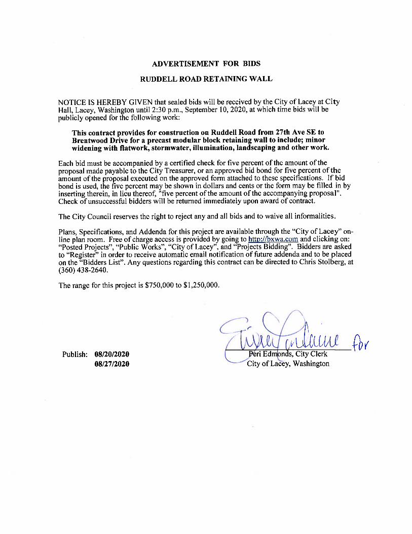
Advertisement for Bids ........................................................................................................ i
INSTRUCTIONS
Instructions to Bidders .................................................................................................... A-1 Bidder's Checklist ........................................................................................................... A-2
BID DOCUMENTS
Proposal & Bid Sheet .......................................................................................................B-1 Bid Bond Form ................................................................................................................B-4 Non-Collusion Certificate ................................................................................................B-5 Certification of Compliance with Wage Payment Statutes..............................................B-6 Subcontractor List ............................................................................................................B-7
CONTRACT DOCUMENTS
Construction Contract ......................................................................................................C-1 Performance Bond Form ..................................................................................................C-4 Declaration of Option for Management of Statutory Retained Percentage. ....................C-6
AMENDMENTS AND SPECIAL PROVISIONS
Table of Contents ................................................................................................................ ii Amendments ................................................................................................................... D-1 Special Provisions ..........................................................................................................D-46
APPPENDIX
PREVAILING MINIMUM HOURLY RATES
State Wage Rates ............................................................................................................. F-1

A INSTRUCTIONS

A-1
INSTRUCTIONS TO BIDDERS Bidders shall examine contract and bid documents and the site and shall satisfy themselves as to conditions that exist. Each Bidder shall submit to the City Clerk, Lacey, Washington a sealed bid endorsed upon the outside wrapper with “Ruddell Road Retaining Walls” at the time and place designated in the advertisement. Bids may be delivered in person to Lacey City Hall, 420 College Street SE, or by mail to City of Lacey 420 College St SE Lacey, WA 98503. The City of Lacey is committed to offering reasonable accommodations to persons with disabilities. We invite any person with special needs to contact the City Clerk at (360) 491-3212 at least seventy-two (72) hours before the meeting to discuss any special accommodations that may be necessary. Citizens with hearing impairment may call the TDD line at (800) 833-6388. Each Bidder shall complete the proposal with prices in figures with the extension properly computed. The proposal must be properly signed by a duly authorized agent. Proposal must acknowledge addenda, if any, received. If alternates are included in the proposal the Bidder shall complete the alternates. The City will award the contract to the lowest responsible Bidder as determined by the Special Provisions. The City reserves the right to delete alternates after award. Each bid shall include properly executed bid surety as outlined in the Advertisement and the Proposal. Each Proposal must be accompanied by a signed Affidavit of Non-Collusion. The City does not pre-qualify Bidders. However, if the apparent low Bidder has not already been determined qualified, the City shall afford seven (7) days after notification for the low Bidder to provide evidence for evaluation, as to capability to perform the work. The evaluation will include consideration of experience, personnel, equipment, financial resources as well as performance record. The information must be sufficient to enable the Bidder to obtain the required qualification rating prior to the award of the contract. No bidder may withdraw his bid after the hour set for the opening of bids or before award of the contract unless said award is delayed for a period of forty-five (45) days.
CONTRACT PARTS The contract to be executed as a result of this bid consists of multiple parts, all of which pertain as if fully attached hereto and Bidder shall consider all parts as a complete document. In the event of discrepancies between the various parts, precedent shall be in the following order:
1. Contract Form,2. Addenda (if any),3. Proposal Form,4. Special Provisions,5. Technical Specifications, if included,6. Contract Plans,7. Amendments to the Standard Specifications,8. WSDOT Standard Specifications for Road, Bridge, and Municipal Construction,9. City of Lacey Development Guidelines and Public Works Standards, and10. WSDOT Standard Plans for Road, Bridge and Municipal Construction
• The Bidder is directed to complete and return the forms in Section B as a bid proposal.

A-2
BIDDER'S CHECKLIST
The bidder's attention is especially called to the following forms which must be executed in full as required, and submitted with the bid proposal: 1. Proposal: The unit prices bid must be shown in the space provided. 2. Proposal Signature Sheet: To be filled in and signed by the bidder. All addenda must be
acknowledged. 3. Bid Deposit: Any bid shall be accompanied by a deposit of cash, certified check, cashier's
check, or surety bond, in an amount equal to at least five percent (5%) of the total amount bid. Checks shall be payable to the City Clerk, City of Lacey, Washington. If a surety bond is used, it shall be submitted on a form furnished by the Commission and signed by the bidder and his surety company. The sureties' "attorney-in-fact" must be registered with the Washington State Insurance Commissioner. The power of attorney must also be submitted with the bond. See Specification section 1-02.7 for more information.
4. Non-Collusion and Debarment Affidavit 5. Subcontractors List The following form must be submitted within 24 hours following the bid submittal deadlines. 6. Certification of Compliance with Wage Payment Statutes The following must be completed before the contract can be awarded: 7. L&I training on the requirements related to public works and prevailing wages per RCW
39.04.350 The following forms are to be executed after the contract is awarded: 8. Contract: This agreement to be executed by the successful bidder 9. Performance and Payment Bond 10. Insurance Certificate
Bidder’s Checklist 1. Proposal 2. Proposal Signature Sheet
Addenda Acknowledged 3. Bid Deposit
Power of Attorney included if applicable 4. Non-Collusion and Debarment Affidavit 5. Subcontractor List 6. Certification of Compliance with Wage Payment Statutes 7. L&I Public Works Prevailing Wage Training

B BID DOCUMENTS

Contract Proposal
CITY OF LACEY
Federal Aid Project Number:
WSDOT Contract Number:
Lacey Contract Number: PW 2017-16
To: The Honorable Mayor and Council, Lacey, Washington
The undersigned, as bidder, has examined the bid documents, contract and bond forms, and the general and technical specifications, all as prepared by the Public Works Department, City of Lacey.
The undersigned, as bidder, proposes to furnish all material and perform all labor in accordance with specifications at the following prices.
Bidder must fill in unit prices in figures for each item and total.
Bidder shall sign this proposal form, furnish bid security and sign the enclosed affidavit.
DATE: _________________________________
TIB Contract Number:
A General
Quantity Unit Item ID Item Description Unit Price Extended PriceNo.
10000 MC 104-010 Minor Change $1.00 $10,000.00A1
1 LS 105-010 Record Drawing $5,000.00 $5,000.00A2
1 LS 107-010 SPCC Plan LUMP SUMA3
1 LS 109-010 Mobilization LUMP SUMA4
1600 HR 110-040 FlaggersA5
100 SF 110-050 Construction Signs Class AA6
800 HR 110-070 Portable Changeable Message SignA7
1 LS 201-010 Clearing and Grubbing LUMP SUMA8
1 LS 202-510 Removal of Structures and Obstructions LUMP SUMA9
2584 CY 203-010 Roadway Excavation Incl. HaulA10
1 LS 205-510 Trench Safety System LUMP SUMA11
20 CY 209-080 Controlled Density FillA12
455 TN 404-020 Crushed Surfacing Top CourseA13
50 TN 504-011 HMA Cl. 1/2" PG 58H-22A14
2 EA 704-950 Connect to Existing Storm MainA15
625 TN 708-670 Gravel Backfill For WallsA16
40 HR 708-810 Utility PotholingA17
1600 LF 801-120 High Visibility Silt FenceA18
B - 1

0.3 AC 801-550 Seeding, Fertilizing, and MulchingA19
1 LS 801-680 Erosion/Water Pollution Control LUMP SUMA20
450 CY 802-010 Topsoil Type AA21
25 CY 802-220 Bark or Wood Chip MulchA22
24 EA 802-810 Tree GrateA23
1 LS 803-005 Irrigation System LUMP SUMA24
180 LF 804-010 Cement Conc. Traffic Curb and GutterA25
1 LS 805-510 Lawn and Landscape Restoration LUMP SUMA26
1540 SY 814-510 Cement Conc. SidewalkA27
8 EA 814-545 Cement Concrete RampA28
1 LS 820-010 ITS System LUMP SUMA29
1 LS 820-505 Illumination System LUMP SUMA30
1400 LF 831-510 Wood FenceA31
8200 SF 832-510 Gravity Block WallA32
1600 LF 834-510 Temporary Chain Link FenceA33
1 LS 850-792 Project Closeout $5,000.00 $5,000.00A34
35 EA 8SH-590 Prunus Lauroceraus (Laurel)A35
47 EA 8SH-592 Prunus Laurocerasus (Mount Vernon Laurel)A36
16 EA 8TR-259 Fraxinus Pennsylvanica 'Rugby' (Prairie Spire)A37
8 EA 8TR-660 Styrax japonicus (Japanese Snowbell)A38
30 EA 8TR-766 Thuja Occidentalis 'Smaragd' (Emerald Green Arborvatae)A39
Tax Rate (%) : 0.00 Tax:
Schedule A Subtotal:
Schedule A Total:
$0.00
Contract Total:(All Schedules)
B - 2

The undersigned also agrees as follows:
1. Within 10 calendar days after the contract is awarded, to execute the contract and to furnish to the City of Lacey, Washington a satisfactory contract bond, guaranteeing the faithful performance of the work.
2. Enclosed with this proposal is a cashier’s check or certified check for $_____________ or a bid bond in the sum of $______________ which it is agreed shall be collected and retained by the City of Lacey as liquidated damages in the event this proposal is accepted by the City of Lacey with 45 calendar days after the receipt of bids and the undersigned fails to execute the contract and the required bond with the City of Lacey, under the conditions thereof, within 10 calendar days after the undersigned is notified that said proposal has been accepted, otherwise said check or bond shall be returned to the undersigned upon demand.
3. That this proposal cannot be withdrawn within 45 days after receipt of bids.
4. That it is the understanding that the City of Lacey may accept or reject any or all bids.
5. The undersigned hereby agrees to pay for labor not less than the prevailing rates of wages or less than the hourly minimum rates of wages set forth in the special provisions for the project.
Addenda Receipt Acknowledged
_______,_______,_______
Signature of Bidder Date
Firm Name Please Print Phone
Address of Bidder:
Name and Address of Firm Members:
Signature of Bidder (if a Corporation)
Title:
Firm Name: Phone:
Business Address:
Officers Address
Incorporated under the Laws of the State of
President:
Secretary:
Treasurer:
(If an Individual, Partnership, or Non-Incorporated organization)
B - 3

B-4
BID BOND FORM
Herewith find deposit in the form of a certified check or bid bond in the amount of $____________________, which amount is not less than five percent (5%) of the total bid.
Signature
BID BOND
KNOW ALL MEN BY THESE PRESENTS:
That we, ,as Principal and ,as Surety are held and firmly bound unto the City of Lacey, as Obligee, in the penal sum of
Dollars, for the payment of which the Principal and the Surety bind themselves, their heirs, executors, successors and assigns, jointly and severally, by these presents. The condition of this obligation is such that if the Obligee shall make any award to the Principal for:
according to the terms of the proposal or bid made by the Principal therefore, and the Principal shall duly make and enter into a contract with the Obligee in accordance with the terms of said proposal or bid and award and shall give bond for the faithful performance thereof, with Surety or Sureties approved by the Obligee; or if the Principal shall, in case of failure to so do, pay and forfeit to the Obligee the penal amount of the deposit specified in the call for bids, then this obligation shall be null and void; otherwise it shall be and remain in full force and effect and the Surety shall forthwith pay and forfeit to the Obligee, as penalty and liquidated damages, the amount of this bond.
SIGNED, SEALED AND DATED THIS day of ,20
Surety Principal
,20
Received return of deposit in the sum of $
B-5
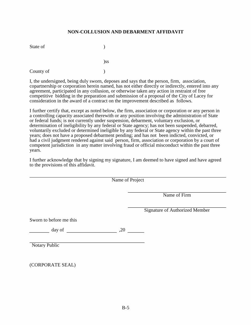
NON-COLLUSION AND DEBARMENT AFFIDAVIT State of ) )ss County of ) I, the undersigned, being duly sworn, deposes and says that the person, firm, association, copartnership or corporation herein named, has not either directly or indirectly, entered into any agreement, participated in any collusion, or otherwise taken any action in restraint of free competitive bidding in the preparation and submission of a proposal of the City of Lacey for consideration in the award of a contract on the improvement described as follows. I further certify that, except as noted below, the firm, association or corporation or any person in a controlling capacity associated therewith or any position involving the administration of State or federal funds; is not currently under suspension, debarment, voluntary exclusion, or determination of ineligibility by any federal or State agency; has not been suspended, debarred, voluntarily excluded or determined ineligible by any federal or State agency within the past three years; does not have a proposed debarment pending; and has not been indicted, convicted, or had a civil judgment rendered against said person, firm, association or corporation by a court of competent jurisdiction in any matter involving fraud or official misconduct within the past three years. I further acknowledge that by signing my signature, I am deemed to have signed and have agreed to the provisions of this affidavit.
Name of Project Name of Firm
Signature of Authorized Member
Sworn to before me this day of ,20
Notary Public
(CORPORATE SEAL)

B-6
CERTIFICATION OF COMPLIANCE WITH WAGE PAYMENT STATUTES
The bidder hereby certifies that, within the three-year period immediately preceding the bid solicitation date, the bidder is not a “willful” violator, as defined in RCW 49.48.082, of any provision of chapters 49.46, 49.48, or 49.52 RCW, as determined by a final and binding citation and notice of assessment issued by the Department of Labor and Industries or through a civil judgment entered by a court of limited or general jurisdiction. I certify under penalty of perjury under the laws of the State of Washington that the foregoing is true and correct.
Bidder’s Business Name
Signature of Authorized Official*
Printed Name
Title
Date
City
State
Check One: Sole Proprietorship ☐ Partnership ☐ Joint Venture ☐ Corporation ☐
State of Incorporation, or if not a corporation, State where business entity was formed:
If a co-partnership, give firm name under which business is transacted:
* If a corporation, proposal must be executed in the corporate name by the president or vice-president (or any other corporate officer accompanied by evidence of authority to sign). If a co-partnership, proposal must be executed by a partner. This form must be submitted with the Bid Proposal or as a Supplement to the Bid no later than 24 hours after the time for delivery of the Bid Proposal, as provided for in Section 1-02.9 of the Contract Provisions.

B-7
SUBCONTRACTOR LIST Prepared in compliance with RCW 39.30.060 as amended
To Be Submitted with the Bid Proposal
Project Name: Failure to list subcontractors with whom the bidder, if awarded the contract, will directly subcontract for performance of the work of structural steel installation and rebar installation, heating, ventilation and air conditioning, plumbing, as described in Chapter 18.106RCW, and electrical, as described in Chapter 19.28 RCW or naming more than one subcontractor to perform the same work will result in your bid being non-responsive and therefore void. Subcontractor(s) with whom the bidder will directly subcontract that are proposed to perform the work of structural steel installation and rebar installation, heating, ventilation and air conditioning, plumbing, as described in Chapter 18.106 RCW, and electrical as described in Chapter 19.28 RCW must be listed below. The work to be performed is to be listed below the subcontractor(s) name. To the extent the Project includes one or more categories of work referenced in RCW 39.30.060, and no subcontractor is listed below to perform such work, the bidder certifies that the work will either (i) be performed by the bidder itself, or (ii) be performed by a lower tier subcontractor who will not contract directly with the bidder. Subcontractor Name: Work to be Performed: Structural steel installation and rebar installation
Subcontractor Name: Work to be Performed: Heating ventilation and air conditioning
Subcontractor Name: Work to be Performed: Plumbing
Subcontractor Name: Work to be Performed: Electrical
Subcontractor Name: Work to be Performed:
* Bidder’s are notified that is the opinion of the enforcement agency that PVC or metal conduit, junction boxes, etc, are considered electrical equipment and therefore considered part of electrical work, even if the installation is for future use and no wiring or electrical current is connected during the project.

C CONTRACT
DOCUMENTS

C-1
Contract Number PW
CONSTRUCTION CONTRACT THIS AGREEMENT, made and entered into this _____ day of ______________, 20_______ , between the City of Lacey, hereinafter called Owner, under and by virtue of the charter, laws and ordinances of the said Owner and the laws of the State of Washington, and ___________________________________________________ hereinafter called Contractor, WITNESSETH: That in consideration of the payment, covenants and agreement hereinafter mentioned, attached and made a part of this Agreement, to be made and performed by the parties hereto, the parties covenant and agree as follows regarding:
1. The Contractor shall do all work and furnish all tools, materials and equipment in accordance with and as described in the attached Plans and Specifications, and in full compliance with the terms, conditions and stipulations herein set forth and attached, now referred to and by such reference incorporated herein and made a part hereof as fully for all purposes as if here set forth at length, and shall perform any alterations in or in addition to the work covered by this Contract and every part thereof and any force account work which may be ordered as provided in this Contract and every part thereof.
The Contractor shall provide and bear the expense of all materials, labor, equipment, tools, implements and conveniences and things of every description that may be requisite for the transfer of materials and for constructing and completing the work provided for in this Contract and every part thereof, except such as are mentioned in the Specifications to be furnished by the Owner.
2. The Owner hereby promises and agrees with the Contractor to employ, and does employ the Contractor to provide the materials and to do and cause to be done the above described work and to complete and finish the same according to the attached Plans and Specifications and the schedule of unit or itemized prices hereto attached, at the time and in the manner and upon the conditions provided for in this Contract and every part thereof.
3. Contractor, for himself and for his heirs, executors, administrators, successors, assigns, does hereby agree to the full performance of all the covenants herein contained upon the part of Contractor.
4. It is further provided that no liability shall attach to Owner or Agent thereof by reason of entering into this Contract, except as expressly provided herein.
5. Payments will be made under the Contract according to the schedule of rates and prices and the specification attached and made a part thereof. Partial payments under the Contract will be made at the request of the Contractor not more than once each month upon approval of the Owner, as hereinafter specified, provided they are in accordance with the provisions of RCW 60.28.010. There will be reserved and retained from monies
C-2
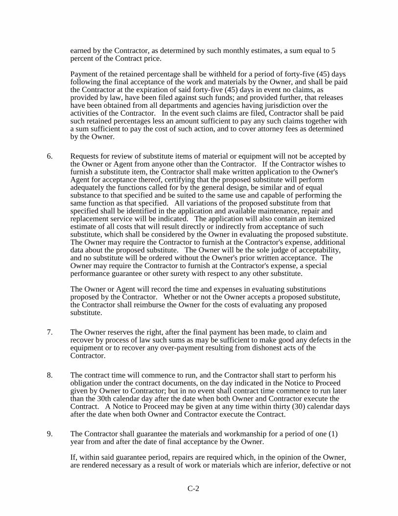
earned by the Contractor, as determined by such monthly estimates, a sum equal to 5 percent of the Contract price.
Payment of the retained percentage shall be withheld for a period of forty-five (45) days following the final acceptance of the work and materials by the Owner, and shall be paid the Contractor at the expiration of said forty-five (45) days in event no claims, as provided by law, have been filed against such funds; and provided further, that releases have been obtained from all departments and agencies having jurisdiction over the activities of the Contractor. In the event such claims are filed, Contractor shall be paid such retained percentages less an amount sufficient to pay any such claims together with a sum sufficient to pay the cost of such action, and to cover attorney fees as determined by the Owner.
6. Requests for review of substitute items of material or equipment will not be accepted by the Owner or Agent from anyone other than the Contractor. If the Contractor wishes to furnish a substitute item, the Contractor shall make written application to the Owner's Agent for acceptance thereof, certifying that the proposed substitute will perform adequately the functions called for by the general design, be similar and of equal substance to that specified and be suited to the same use and capable of performing the same function as that specified. All variations of the proposed substitute from that specified shall be identified in the application and available maintenance, repair and replacement service will be indicated. The application will also contain an itemized estimate of all costs that will result directly or indirectly from acceptance of such substitute, which shall be considered by the Owner in evaluating the proposed substitute. The Owner may require the Contractor to furnish at the Contractor's expense, additional data about the proposed substitute. The Owner will be the sole judge of acceptability, and no substitute will be ordered without the Owner's prior written acceptance. The Owner may require the Contractor to furnish at the Contractor's expense, a special performance guarantee or other surety with respect to any other substitute.
The Owner or Agent will record the time and expenses in evaluating substitutions proposed by the Contractor. Whether or not the Owner accepts a proposed substitute, the Contractor shall reimburse the Owner for the costs of evaluating any proposed substitute.
7. The Owner reserves the right, after the final payment has been made, to claim and recover by process of law such sums as may be sufficient to make good any defects in the equipment or to recover any over-payment resulting from dishonest acts of the Contractor.
8. The contract time will commence to run, and the Contractor shall start to perform his obligation under the contract documents, on the day indicated in the Notice to Proceed given by Owner to Contractor; but in no event shall contract time commence to run later than the 30th calendar day after the date when both Owner and Contractor execute the Contract. A Notice to Proceed may be given at any time within thirty (30) calendar days after the date when both Owner and Contractor execute the Contract.
9. The Contractor shall guarantee the materials and workmanship for a period of one (1) year from and after the date of final acceptance by the Owner.
If, within said guarantee period, repairs are required which, in the opinion of the Owner, are rendered necessary as a result of work or materials which are inferior, defective or not

C-3
in accordance with the terms of the Contract, the Contractor shall, promptly upon receipt of notice from the Owner, and without expense to the Owner, (a) correct all defects and place in satisfactory condition in every particular all of such guaranteed work and materials; (b) make good all damage which in the opinion of the Owner is caused by such defects; and (c) make good any other work or material or the equipment and contents of a building, structure or site disturbed in fulfilling any such guarantee.
If the Contractor, after notice, fails within ten (10) days to proceed to comply to the terms of this guarantee, the Owner may have the defects corrected, and the Contractor and his Surety shall be liable for all expense incurred, provided, however, that in case of an emergency where, in the opinion of the Owner, delay would cause serious loss or damage, repairs may be made without notice being given to the Contractor and the Contractor shall pay the cost thereof.
IN WITNESS WHEREOF, the said Contractor has executed this instrument and the City Manager, pursuant to resolution duly adopted, has caused this instrument to be executed in the name of the City of Lacey the day and year first above-written. Contractor
Contractor’s Registration Number (UBI No.)
City of Lacey Business License Number City Manager
ATTEST: By:
City Clerk APPROVED AS TO FORM: By :
City Attorney

C-4
PERFORMANCE/PAYMENT BOND FORM KNOW ALL MEN BY THESE PRESENTS: That _________________________________________________________________of _________________________________________________________, as Principal, and _________________________________________________________, as Surety, are jointly and severally held and bound unto the _____________________________in the penal sum of ______________________________Dollars ($ _______________ ) for the payment of which we jointly and severally bind ourselves, our heirs, executors, administrators, and assigns, firmly by these presents. The condition of this bond is such that, WHEREAS, on the _______ day of __________________________, 20______, the said Principal made and entered into a certain contract with the CITY OF LACEY, Washington, by the terms, conditions and provisions of which contract the said Principal agreed to undertake and complete the work as per specifications made a part of said contract, which contract as so executed is incorporated herein and made a part hereof as fully for all purposes as if here set forth at length. NOW, THEREFORE, if the Principal shall well and truly perform and fulfill all the undertakings, covenants, terms and conditions, and agreements of said Contract during the original term of said Contract and any extensions thereof that may be granted by the City of Lacey, Washington, with or without notice to the Surety; and during the life of any guaranty required under the Contract; and shall also well and truly perform and fulfill all the undertakings, covenants, terms and conditions, and agreements of any and all duly authorized modifications of said Contract that may hereafter be made; notice of which modifications to the Surety being hereby waived; and furthermore, shall make prompt payment to all laborers, mechanics, subcontractors and materialmen and all persons who shall supply such contractor or subcontractor with provisions and supplies for performance of said Contract, then this obligation to be void, otherwise to remain in full force and effect. WITNESS our hand this day of , 20
Principal Surety

C-5
Address of local office and agent of Surety
APPROVED AS TO FORM: By: , 20
City Attorney
C-6
DECLARATION OF OPTION FOR MANAGEMENT OF STATUTORY RETAINED PERCENTAGE
A. I hereby elect to have the retained percentage of this contract held in a fund by the City of
Lacey until forty-five (45) days following final acceptance of the work.
Contractor (please print)
Date Signature
B. I hereby elect to have the City of Lacey invest the retained percentage of this contract from time to time as such retained percentage accrues and in accordance with RCW Ch. 60.28.
I hereby designate ____________________________________________ as the repository for the escrow of said funds.
I hereby further agree to be fully responsible for payment of all costs or fees incurred as a result of placing said percentage in escrow and investing it as authorized by statue.
The City of Lacey shall not be liable in any way for any costs or fees in connection therewith.
Contractor (please print)
Date Signature

D AMENDMENTS AND
SPECIAL PROVISIONS

TABLE OF CONTENTS
WSDOT AMENDMENTS TO THE STANDARD SPECIFICATIONS
1-01 DEFINITIONS AND TERMS .......................................................................................................................... 1 1-02 BID PROCEDURES AND CONDITIONS ...................................................................................................... 1 1-03 AWARD AND EXECUTION OF CONTRACT .............................................................................................. 2 1-05 CONTROL OF WORK .................................................................................................................................... 2 1-06 CONTROL OF MATERIAL ............................................................................................................................ 3 1-07 LEGAL RELATIONS AND RESPONSIBILITIES TO THE PUBLIC............................................................ 5 1-08 PROSECUTION AND PROGRESS ................................................................................................................ 9 1-09 MEASUREMENT AND PAYMENT .............................................................................................................. 9 2-02 REMOVAL OF STRUCTURES AND OBSTRUCTIONS ............................................................................ 10 2-09 STRUCTURE EXCAVATION ...................................................................................................................... 10 3-01 PRODUCTION FROM QUARRY AND PIT SITES ..................................................................................... 10 4-04 BALLAST AND CRUSHED SURFACING .................................................................................................. 11 6-02 CONCRETE STRUCTURES ......................................................................................................................... 11 8-01 EROSION CONTROL AND WATER POLLUTION CONTROL ................................................................ 14 8-02 ROADSIDE RESTORATION ....................................................................................................................... 27 8-04 CURBS, GUTTERS, AND SPILLWAYS ...................................................................................................... 27 8-06 CEMENT CONCRETE DRIVEWAY ENTRANCES ................................................................................... 28 8-14 CEMENT CONCRETE SIDEWALKS .......................................................................................................... 28 8-20 ILLUMINATION, TRAFFIC SIGNAL SYSTEMS, INTELLIGENT TRANSPORTATION SYSTEMS,
AND ELECTRICAL ...................................................................................................................................... 28 8-21 PERMANENT SIGNING .............................................................................................................................. 29 8-22 PAVEMENT MARKING .............................................................................................................................. 29 9-02 BITUMINOUS MATERIALS ....................................................................................................................... 30 9-03 AGGREGATES ............................................................................................................................................. 31 9-04 JOINT AND CRACK SEALING MATERIALS ............................................................................................ 36 9-05 DRAINAGE STRUCTURES AND CULVERTS .......................................................................................... 36 9-06 STRUCTURAL STEEL AND RELATED MATERIALS ............................................................................. 37 9-21 RAISED PAVEMENT MARKERS (RPM) ................................................................................................... 38 9-28 SIGNING MATERIALS AND FABRICATION ........................................................................................... 39 9-29 ILLUMINATION, SIGNAL, ELECTRICAL ................................................................................................ 40 9-34 PAVEMENT MARKING MATERIAL ......................................................................................................... 45
SPECIAL PROVISIONS
INTRODUCTION TO THE SPECIAL PROVISIONS ............................................................................................... 46 DESCRIPTION OF WORK ........................................................................................................................................ 46 1-01 DEFINITIONS AND TERMS ........................................................................................................................ 46 1-02 BID PROCEDURES AND CONDITIONS .................................................................................................... 48 1-03 AWARD AND EXECUTION OF CONTRACT ............................................................................................ 54 1-04 SCOPE OF THE WORK ................................................................................................................................ 56 1-05 CONTROL OF WORK .................................................................................................................................. 57 1-06 CONTROL OF MATERIAL .......................................................................................................................... 63 1-07 LEGAL RELATIONS AND RESPONSIBILITIES TO THE PUBLIC.......................................................... 65 1-08 PROSECUTION AND PROGRESS .............................................................................................................. 72 1-09 MEASUREMENT AND PAYMENT ............................................................................................................ 77 1-10 TEMPORARY TRAFFIC CONTROL ........................................................................................................... 79 2-02 REMOVAL OF STRUCTURES AND OBSTRUCTIONS ............................................................................ 81 2-03 ROADWAY EXCAVATION AND EMBANKMENT .................................................................................. 83 2-05 TRENCH SAFETY SYSTEM ........................................................................................................................ 84 2-07 WATERING ................................................................................................................................................... 85 2-09 STRUCTURE EXCAVATION ...................................................................................................................... 86
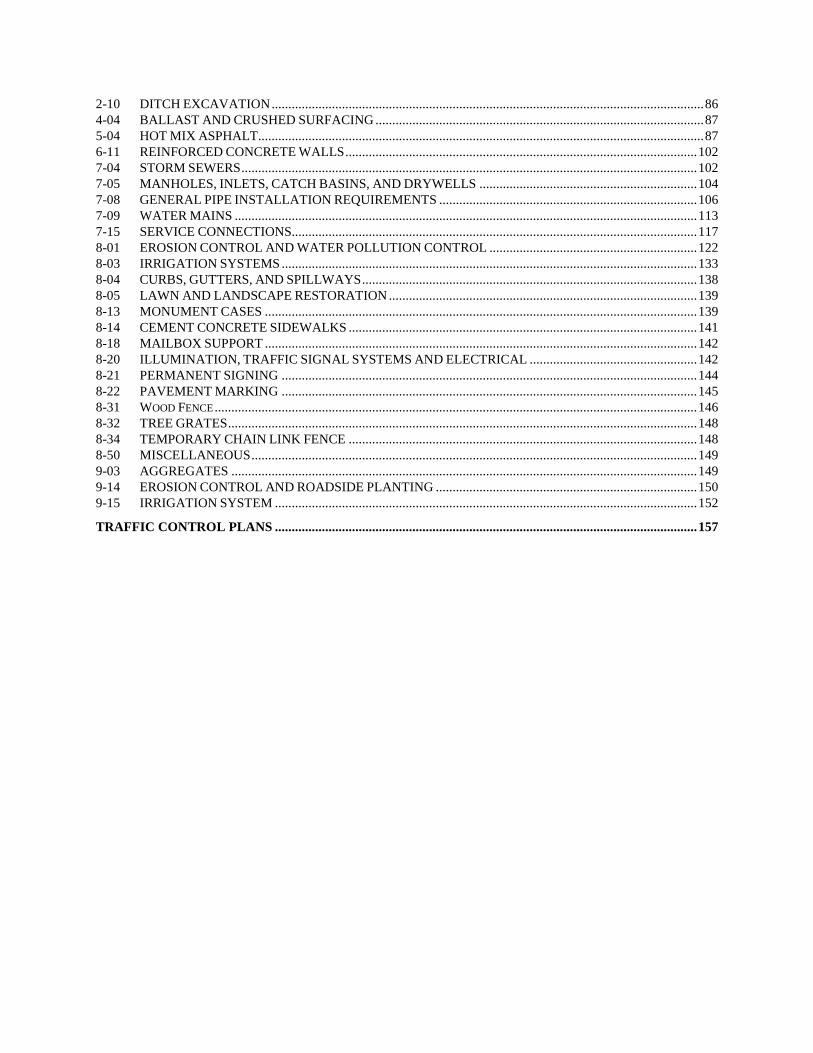
2-10 DITCH EXCAVATION ................................................................................................................................. 86 4-04 BALLAST AND CRUSHED SURFACING .................................................................................................. 87 5-04 HOT MIX ASPHALT..................................................................................................................................... 87 6-11 REINFORCED CONCRETE WALLS ......................................................................................................... 102 7-04 STORM SEWERS ........................................................................................................................................ 102 7-05 MANHOLES, INLETS, CATCH BASINS, AND DRYWELLS ................................................................. 104 7-08 GENERAL PIPE INSTALLATION REQUIREMENTS ............................................................................. 106 7-09 WATER MAINS .......................................................................................................................................... 113 7-15 SERVICE CONNECTIONS......................................................................................................................... 117 8-01 EROSION CONTROL AND WATER POLLUTION CONTROL .............................................................. 122 8-03 IRRIGATION SYSTEMS ............................................................................................................................ 133 8-04 CURBS, GUTTERS, AND SPILLWAYS .................................................................................................... 138 8-05 LAWN AND LANDSCAPE RESTORATION ............................................................................................ 139 8-13 MONUMENT CASES ................................................................................................................................. 139 8-14 CEMENT CONCRETE SIDEWALKS ........................................................................................................ 141 8-18 MAILBOX SUPPORT ................................................................................................................................. 142 8-20 ILLUMINATION, TRAFFIC SIGNAL SYSTEMS AND ELECTRICAL .................................................. 142 8-21 PERMANENT SIGNING ............................................................................................................................ 144 8-22 PAVEMENT MARKING ............................................................................................................................ 145 8-31 WOOD FENCE ................................................................................................................................................ 146 8-32 TREE GRATES ............................................................................................................................................ 148 8-34 TEMPORARY CHAIN LINK FENCE ........................................................................................................ 148 8-50 MISCELLANEOUS ..................................................................................................................................... 149 9-03 AGGREGATES ........................................................................................................................................... 149 9-14 EROSION CONTROL AND ROADSIDE PLANTING .............................................................................. 150 9-15 IRRIGATION SYSTEM .............................................................................................................................. 152
TRAFFIC CONTROL PLANS .............................................................................................................................. 157
D-1
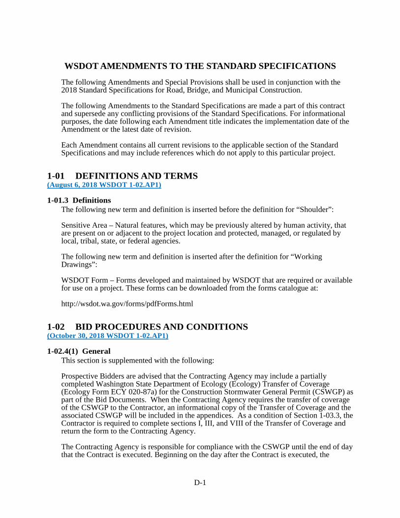
WSDOT AMENDMENTS TO THE STANDARD SPECIFICATIONS
The following Amendments and Special Provisions shall be used in conjunction with the 2018 Standard Specifications for Road, Bridge, and Municipal Construction. The following Amendments to the Standard Specifications are made a part of this contract and supersede any conflicting provisions of the Standard Specifications. For informational purposes, the date following each Amendment title indicates the implementation date of the Amendment or the latest date of revision. Each Amendment contains all current revisions to the applicable section of the Standard Specifications and may include references which do not apply to this particular project.
1-01 DEFINITIONS AND TERMS (August 6, 2018 WSDOT 1-02.AP1)
1-01.3 Definitions The following new term and definition is inserted before the definition for “Shoulder”: Sensitive Area – Natural features, which may be previously altered by human activity, that are present on or adjacent to the project location and protected, managed, or regulated by local, tribal, state, or federal agencies. The following new term and definition is inserted after the definition for “Working Drawings”: WSDOT Form – Forms developed and maintained by WSDOT that are required or available for use on a project. These forms can be downloaded from the forms catalogue at: http://wsdot.wa.gov/forms/pdfForms.html
1-02 BID PROCEDURES AND CONDITIONS (October 30, 2018 WSDOT 1-02.AP1)
1-02.4(1) General This section is supplemented with the following: Prospective Bidders are advised that the Contracting Agency may include a partially completed Washington State Department of Ecology (Ecology) Transfer of Coverage (Ecology Form ECY 020-87a) for the Construction Stormwater General Permit (CSWGP) as part of the Bid Documents. When the Contracting Agency requires the transfer of coverage of the CSWGP to the Contractor, an informational copy of the Transfer of Coverage and the associated CSWGP will be included in the appendices. As a condition of Section 1-03.3, the Contractor is required to complete sections I, III, and VIII of the Transfer of Coverage and return the form to the Contracting Agency. The Contracting Agency is responsible for compliance with the CSWGP until the end of day that the Contract is executed. Beginning on the day after the Contract is executed, the

D-2
Contractor shall assume complete legal responsibility for compliance with the CSWGP and full implementation of all conditions of the CSWGP as they apply to the Contract Work.
1-02.5 Proposal Forms The first sentence of the first paragraph is revised to read: At the request of a Bidder, the Contracting Agency will provide a physical Proposal Form for any project on which the Bidder is eligible to Bid.
1-03 AWARD AND EXECUTION OF CONTRACT (January 2, 2018 WSDOT 1-03.AP1)
1-03.3 Execution of Contract The first paragraph is revised to read: Within 20 calendar days after the Award date, the successful Bidder shall return the signed Contracting Agency-prepared Contract, an insurance certification as required by Section 1-07.18, a satisfactory bond as required by law and Section 1-03.4, the Transfer of Coverage form for the Construction Stormwater General Permit with sections I, III, and VIII completed when provided, and shall be registered as a contractor in the state of Washington.
1-03.5 Failure to Execute Contract The first sentence is revised to read: Failure to return the insurance certification and bond with the signed Contract as required in Section 1-03.3, or failure to provide Disadvantaged, Minority or Women’s Business Enterprise information if required in the Contract, or failure or refusal to sign the Contract, or failure to register as a contractor in the state of Washington, or failure to return the completed Transfer of Coverage for the Construction Stormwater General Permit to the Contracting Agency when provided shall result in forfeiture of the proposal bond or deposit of this Bidder.
1-05 CONTROL OF WORK (August 6, 2018 WSDOT 1-05.AP1)
1-05.5 Vacant This section, including title, is revised to read:
1-05.5 Tolerances Geometrical tolerances shall be measured from the points, lines, and surfaces defined in Contract documents. A plus (+) tolerance increases the amount or dimension to which it applies, or raises a deviation from level. A minus (-) tolerance decreases the amount or dimension to which it applies, or lowers a deviation from level. Where only one signed tolerance is specified (+ or -), there is no specified tolerance in the opposing direction. Tolerances shall not be cumulative. The most restrictive tolerance shall control. Tolerances shall not extend the Work beyond the Right of Way or other legal boundaries identified in the Contract documents. If application of tolerances causes the extension of the
D-3
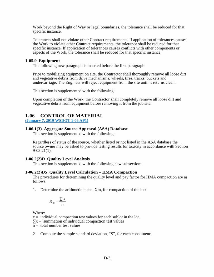
Work beyond the Right of Way or legal boundaries, the tolerance shall be reduced for that specific instance. Tolerances shall not violate other Contract requirements. If application of tolerances causes the Work to violate other Contract requirements, the tolerance shall be reduced for that specific instance. If application of tolerances causes conflicts with other components or aspects of the Work, the tolerance shall be reduced for that specific instance.
1-05.9 Equipment The following new paragraph is inserted before the first paragraph: Prior to mobilizing equipment on site, the Contractor shall thoroughly remove all loose dirt and vegetative debris from drive mechanisms, wheels, tires, tracks, buckets and undercarriage. The Engineer will reject equipment from the site until it returns clean. This section is supplemented with the following: Upon completion of the Work, the Contractor shall completely remove all loose dirt and vegetative debris from equipment before removing it from the job site.
1-06 CONTROL OF MATERIAL (January 7, 2019 WSDOT 1-06.AP1)
1-06.1(3) Aggregate Source Approval (ASA) Database This section is supplemented with the following: Regardless of status of the source, whether listed or not listed in the ASA database the source owner may be asked to provide testing results for toxicity in accordance with Section 9-03.21(1).
1-06.2(2)D Quality Level Analysis This section is supplemented with the following new subsection:
1-06.2(2)D5 Quality Level Calculation – HMA Compaction The procedures for determining the quality level and pay factor for HMA compaction are as follows: 1. Determine the arithmetic mean, Xm, for compaction of the lot:
nxX m
∑=
Where: x = individual compaction test values for each sublot in the lot. ∑x = summation of individual compaction test values n = total number test values 2. Compute the sample standard deviation, “S”, for each constituent:
D-4
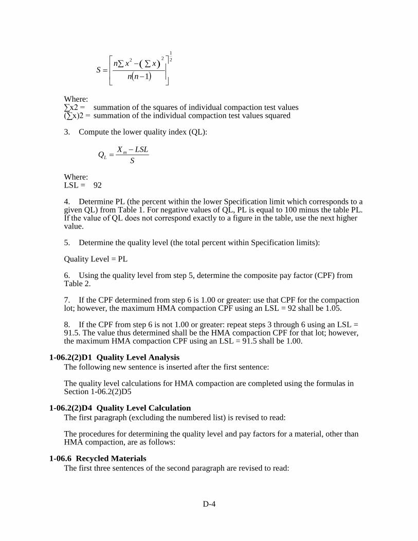
( )( )
21
22
1
−∑−∑
=nn
xxnS
Where: ∑x2 = summation of the squares of individual compaction test values (∑x)2 = summation of the individual compaction test values squared 3. Compute the lower quality index (QL):
S
LSLXQ mL
−=
Where: LSL = 92 4. Determine PL (the percent within the lower Specification limit which corresponds to a given QL) from Table 1. For negative values of QL, PL is equal to 100 minus the table PL. If the value of QL does not correspond exactly to a figure in the table, use the next higher value. 5. Determine the quality level (the total percent within Specification limits): Quality Level = PL 6. Using the quality level from step 5, determine the composite pay factor (CPF) from Table 2. 7. If the CPF determined from step 6 is 1.00 or greater: use that CPF for the compaction lot; however, the maximum HMA compaction CPF using an LSL = 92 shall be 1.05. 8. If the CPF from step 6 is not 1.00 or greater: repeat steps 3 through 6 using an LSL = 91.5. The value thus determined shall be the HMA compaction CPF for that lot; however, the maximum HMA compaction CPF using an LSL = 91.5 shall be 1.00.
1-06.2(2)D1 Quality Level Analysis The following new sentence is inserted after the first sentence: The quality level calculations for HMA compaction are completed using the formulas in Section 1-06.2(2)D5
1-06.2(2)D4 Quality Level Calculation The first paragraph (excluding the numbered list) is revised to read: The procedures for determining the quality level and pay factors for a material, other than HMA compaction, are as follows:
1-06.6 Recycled Materials The first three sentences of the second paragraph are revised to read:

D-5
The Contractor shall submit a Recycled Material Utilization Plan on WSDOT Form 350-075A within 30 calendar days after the Contract is executed. The plan shall provide the Contractor’s anticipated usage of recycled concrete aggregates for meeting the requirements of these Specifications. The quantity of recycled concrete aggregate will be provided in tons and as a percentage of the Plan quantity for eligible material listed in Section 9-03.21(1)E Table on Maximum Allowable percent (By Weight) of Recycled Material. The last paragraph is revised to read: Within 30 calendar days after Physical Completion, the Contractor shall report the quantity of recycled concrete aggregates that were utilized in the construction of the project for each eligible item listed in Section 9-03.21(1)E. The Contractor’s report shall be provided on WSDOT Form 350-075A, Recycled Materials Reporting.
1-06.6(1)A General Item 1(a) in the second paragraph is revised to read: a. The estimated costs for the Work for each material with 25 percent recycled concrete aggregate. The cost estimate shall include for each material a documented price quote from the supplier with the lowest total cost for the Work.
1-07 LEGAL RELATIONS AND RESPONSIBILITIES TO THE PUBLIC (August 6, 2018 WSDOT 1-07.AP1)
1-07.5 Environmental Regulations This section is supplemented with the following new subsections:
1-07.5(5) U.S. Army Corps of Engineers When temporary fills are permitted, the Contractor shall remove fills in their entirety and the affected areas returned to pre-construction elevations. If a U.S. Army Corps of Engineers permit is noted in Section 1-07.6 of the Special Provisions, the Contractor shall retain a copy of the permit or the verification letter (in the case of a Nationwide Permit) on the worksite for the life of the Contract. The Contractor shall provide copies of the permit or verification letter to all subcontractors involved with the authorized work prior to their commencement of any work in waters of the U.S.
1-07.5(6) U.S. Fish/Wildlife Services and National Marine Fisheries Service The Contracting Agency will provide fish exclusion and handling services if the Work dictates. However, if the Contractor discovers any fish stranded by the project and a Contracting Agency biologist is not available, they shall immediately release the fish into a flowing stream or open water.
1-07.5(1) General The first sentence is deleted and replaced with the following: No Work shall occur within areas under the jurisdiction of resource agencies unless authorized in the Contract. The third paragraph is deleted.

D-6
1-07.5(2) State Department of Fish and Wildlife This section is revised to read: In doing the Work, the Contractor shall: 1. Not degrade water in a way that would harm fish, wildlife, or their habitat. 2. Not place materials below or remove them from the ordinary high water line except as may be specified in the Contract. 3. Not allow equipment to enter waters of the State except as specified in the Contract. 4. Revegetate in accordance with the Plans, unless the Special Provisions permit otherwise. 5. Prevent any fish-threatening silt buildup on the bed or bottom of any body of water. 6. Ensure continuous stream flow downstream of the Work area. 7. Dispose of any project debris by removal, burning, or placement above high-water flows. 8. Immediately notify the Engineer and stop all work causing impacts, if at any time, as a result of project activities, fish are observed in distress or a fish kill occurs. If the Work in (1) through (3) above differs little from what the Contract requires, the Contracting Agency will measure and pay for it at unit Contract prices. But if Contract items do not cover those areas, the Contracting Agency will pay pursuant to Section 1-09.4. Work in (4) through (8) above shall be incidental to Contract pay items.
1-07.5(3) State Department of Ecology This section is revised to read: In doing the Work, the Contractor shall: 1. Comply with Washington State Water Quality Standards. 2. Perform Work in such a manner that all materials and substances not specifically identified in the Contract documents to be placed in the water do not enter waters of the State, including wetlands. These include, but are not limited to, petroleum products, hydraulic fluid, fresh concrete, concrete wastewater, process wastewater, slurry materials and waste from shaft drilling, sediments, sediment-laden water, chemicals, paint, solvents, or other toxic or deleterious materials. 3. Use equipment that is free of external petroleum-based products. 4. Remove accumulations of soil and debris from drive mechanisms (wheels, tracks, tires) and undercarriage of equipment prior to using equipment below the ordinary high water line. 5. Clean loose dirt and debris from all materials placed below the ordinary high water line. No materials shall be placed below the ordinary high water line without the Engineer’s concurrence.
D-7
6. When a violation of the Construction Stormwater General Permit (CSWGP) occurs, immediately notify the Engineer and fill out WSDOT Form 422-011, Contractor ECAP Report, and submit the form to the Engineer within 48 hours of the violation. 7. Once Physical Completion has been given, prepare a Notice of Termination (Ecology Form ECY 020-87) and submit the Notice of Termination electronically to the Engineer in a PDF format a minimum of 7 calendar days prior to submitting the Notice of Termination to Ecology. 8. Transfer the CSWGP coverage to the Contracting Agency when Physical Completion has been given and the Engineer has determined that the project site is not stabilized from erosion. 9. Submit copies of all correspondence with Ecology electronically to the Engineer in a PDF format within four calendar days.
1-07.5(4) Air Quality This section is revised to read: The Contractor shall comply with all regional clean air authority and/or State Department of Ecology rules and regulations. The air quality permit process may include additional State Environment Policy Act (SEPA) requirements. Contractors shall contact the appropriate regional air pollution control authority well in advance of beginning Work. When the Work includes demolition or renovation of any existing facility or structure that contains Asbestos Containing Material (ACM) and/or Presumed Asbestos-Containing Material (PACM), the Contractor shall comply with the National Emission Standards for Hazardous Air Pollutants (NESHAP). Any requirements included in Federal and State regulations regarding air quality that applies to the “owner or operator” shall be the responsibility of the Contractor.
1-07.7(1) General The first sentence of the third paragraph is revised to read: When the Contractor moves equipment or materials on or over Structures, culverts or pipes, the Contractor may operate equipment with only the load-limit restrictions in Section 1-07.7(2). The first sentence of the last paragraph is revised to read: Unit prices shall cover all costs for operating over Structures, culverts and pipes.
1-07.9(1) General The last sentence of the sixth paragraph is revised to read: Generally, the Contractor initiates the request by preparing standard form 1444 Request for Authorization of Additional Classification and Rate, available at https://www.dol.gov/whd/recovery/dbsurvey/conformance.htm, and submitting it to the Engineer for further action.
D-8
1-07.9(2) Posting Notices The second sentence of the first paragraph (up until the colon) is revised to read: The Contractor shall ensure the most current edition of the following are posted: In items 1 through 10, the revision dates are deleted.
1-07.11(2) Contractual Requirements In this section, “creed” is revised to read “religion”. Item numbers 1 through 9 are revised to read 2 through 10, respectively. After the preceding Amendment is applied, the following new item number 1 is inserted: 1. The Contractor shall maintain a Work site that is free of harassment, humiliation, fear, hostility and intimidation at all times. Behaviors that violate this requirement include but are not limited to: a. Persistent conduct that is offensive and unwelcome. b. Conduct that is considered to be hazing. c. Jokes about race, gender, or sexuality that are offensive. d. Unwelcome, unwanted, rude or offensive conduct or advances of a sexual nature which interferes with a person’s ability to perform their job or creates an intimidating, hostile, or offensive work environment. e. Language or conduct that is offensive, threatening, intimidating or hostile based on race, gender, or sexual orientation. f. Repeating rumors about individuals in the Work Site that are considered to be harassing or harmful to the individual’s reputation.
1-07.11(5) Sanctions This section is supplemented with the following: Immediately upon the Engineer’s request, the Contractor shall remove from the Work site any employee engaging in behaviors that promote harassment, humiliation, fear or intimidation including but not limited to those described in these specifications.
1-07.11(6) Incorporation of Provisions The first sentence is revised to read: The Contractor shall include the provisions of Section 1-07.11(2) Contractual Requirements (1) through (5) and the Section 1-07.11(5) Sanctions in every subcontract including procurement of materials and leases of equipment.
1-07.15(1) Spill Prevention, Control, and Countermeasures Plan The last sentence of the first paragraph is revised to read:

D-9
An SPCC Plan template and guidance information is available at http://www.wsdot.wa.gov/environment/technical/disciplines/hazardous-materials/spill-prevent-report.
1-07.18 Public Liability and Property Damage Insurance Item number 1 is supplemented with the following new sentence: This policy shall be kept in force from the execution date of the Contract until the Physical Completion Date.
1-08 PROSECUTION AND PROGRESS (January 7, 2019 WSDOT 1-08.AP1)
1-08.1 Subcontracting The first sentence of the seventh paragraph is revised to read: All Work that is not performed by the Contractor will be considered as subcontracting except: (1) purchase of sand, gravel, crushed stone, crushed slag, batched concrete aggregates, ready-mix concrete, off-site fabricated structural steel, other off-site fabricated items, and any other materials supplied by established and recognized commercial plants; or (2) delivery of these materials to the Work site in vehicles owned or operated by such plants or by recognized independent or commercial hauling companies hired by those commercial plants. The following new paragraph is inserted after the seventh paragraph: The Contractor shall not use businesses (material suppliers, vendors, subcontractors, etc.) with federal purchasing exclusions. Businesses with exclusions are identified using the System for Award Management web page at www.SAM.gov.
1-08.5 Time for Completion Item number 2 of the sixth paragraph is supplemented with the following: f. A copy of the Notice of Termination sent to the Washington State Department of Ecology (Ecology); the elapse of 30 calendar days from the date of receipt of the Notice of Termination by Ecology; and no rejection of the Notice of Termination by Ecology. This requirement will not apply if the Construction Stormwater General Permit is transferred back to the Contracting Agency in accordance with Section 8-01.3(16).
1-08.7 Maintenance During Suspension The fifth paragraph is revised to read: The Contractor shall protect and maintain all other Work in areas not used by traffic. All costs associated with protecting and maintaining such Work shall be the responsibility of the Contractor.
1-09 MEASUREMENT AND PAYMENT (August 6, 2018 WSDOT 1-09.AP1)
1-09.2(1) General Requirements for Weighing Equipment The last paragraph is supplemented with the following:

D-10
When requested by the Engineer, the Contractor’s representative shall collect the tickets throughout the day and provide them to the Engineer’s designated receiver, not later than the end of shift, for reconciliation. Tickets for loads not verified as delivered will receive no pay.
1-09.2(2) Specific Requirements for Batching Scales The last sentence of the first paragraph is revised to read: Batching scales used for concrete or hot mix asphalt shall not be used for batching other materials.
1-09.10 Payment for Surplus Processed Materials The following sentence is inserted after the first sentence of the second paragraph: For Hot Mix Asphalt, the Plan quantity and quantity used will be adjusted for the quantity of Asphalt and quantity of RAP or other materials incorporated into the mix..
2-02 REMOVAL OF STRUCTURES AND OBSTRUCTIONS (April 2, 2018 WSDOT 2-02.AP2)
2-02.3(3) Removal of Pavement, Sidewalks, Curbs, and Gutters In item number 3 of the first paragraph, the second sentence is revised to read: For concrete pavement removal, a second vertical full depth relief saw cut offset 12 to 18 inches from and parallel to the initial saw cut is also required, unless the Engineer allows otherwise.
2-09 STRUCTURE EXCAVATION (April 2, 2018 WSDOT 2-09.AP2)
2-09.2 Materials In the first paragraph, the references to “Portland Cement” and “Aggregates for Portland Cement Concrete” are revised to read: Cement 9-01 Fine Aggregate for Concrete 9-03.1(2)
2-09.3(3)D Shoring and Cofferdams The first sentence of the sixth paragraph is revised to read: Structural shoring and cofferdams shall be designed for conditions stated in this Section using methods shown in Division I Section 5 of the AASHTO Standard Specifications for Highway Bridges Seventeenth Edition – 2002 for allowable stress design, or the AASHTO LRFD Bridge Design Specifications for load and resistance factor design.
3-01 PRODUCTION FROM QUARRY AND PIT SITES (April 2, 2018 WSDOT 3-01.AP3)

D-11
3-01.1 Description The first paragraph is revised to read: This Work shall consist of manufacturing and producing crushed and screened aggregates including pit run aggregates of the kind, quality, and grading specified for use in the construction of concrete, hot mix asphalt, crushed surfacing, maintenance rock, ballast, gravel base, gravel backfill, gravel borrow, riprap, and bituminous surface treatments of all descriptions.
4-04 BALLAST AND CRUSHED SURFACING (April 2, 2018 WSDOT 4-04.AP4)
4-04.3(5) Shaping and Compaction This section is supplemented with the following new paragraph: When using 100% Recycled Concrete Aggregate, the Contractor may submit a written request to use a test point evaluation for compaction acceptance testing in lieu of compacting to 95% of the standard density as determined by the requirements of Section 2-03.3(14)D. The test point evaluation shall be performed in accordance with SOP 738.
6-02 CONCRETE STRUCTURES (April 2, 2018 WSDOT 6-02.AP6)
6-02.1 Description The first sentence is revised to read: This Work consists of the construction of all Structures (and their parts) made of portland cement or blended hydraulic cement concrete with or without reinforcement, including bridge approach slabs.
6-02.2 Materials In the first paragraph, the references to “Portland Cement” and “Aggregates for Portland Cement Concrete” are revised to read: Cement 9-01 Aggregates for Concrete 9-03.1
6-02.3(2) Proportioning Materials The second paragraph is revised to read: Unless otherwise specified, the Contractor shall use Type I or II portland cement or blended hydraulic cement in all concrete as defined in Section 9-01.2(1).
6-02.3(2)A Contractor Mix Design The last sentence of the last paragraph is revised to read: For all other concrete, air content shall be a minimum of 4.5 percent and a maximum of 7.5 percent for all concrete placed above the finished ground line unless noted otherwise.

D-12
6-02.3(2)A1 Contractor Mix Design for Concrete Class 4000D Item number 5 of the first paragraph is deleted. Item number 6 of the first paragraph (after the preceding Amendment is applied) is renumbered to 5.
6-02.3(2)B Commercial Concrete The second paragraph is revised to read: Where concrete Class 3000 is specified for items such as, culvert headwalls, plugging culverts, concrete pipe collars, pipe anchors, monument cases, Type PPB, PS, I, FB and RM signal standards, pedestals, cabinet bases, guardrail anchors, fence post footings, sidewalks, concrete curbs, curbs and gutters, and gutters, the Contractor may use commercial concrete. If commercial concrete is used for sidewalks, concrete curbs, curbs and gutters, and gutters, it shall have a minimum cementitious material content of 564 pounds per cubic yard of concrete, shall be air entrained, and the tolerances of Section 6-02.3(5)C shall apply.
6-02.3(4)D Temperature and Time For Placement The following is inserted after the first sentence of the first paragraph: The upper temperature limit for placement for Class 4000D concrete may be increased to a maximum of 80°F if allowed by the Engineer.
6-02.3(5)C Conformance to Mix Design Item number 1 of the second paragraph is revised to read: 1. Cement weight plus 5 percent or minus 1 percent of that specified in the mix design.
6-02.3(6)A1 Hot Weather Protection The first paragraph is revised to read: The Contractor shall provide concrete within the specified temperature limits. Cooling of the coarse aggregate piles by sprinkling with water is permitted provided the moisture content is monitored, the mixing water is adjusted for the free water in the aggregate and the coarse aggregate is removed from at least 1 foot above the bottom of the pile. Sprinkling of fine aggregate piles with water is not allowed. Refrigerating mixing water or replacing all or part of the mixing water with crushed ice is permitted, provided the ice is completely melted by placing time. The second sentence of the second paragraph is revised to read: These surfaces include forms, reinforcing steel, steel beam flanges, and any others that touch the concrete.
6-02.3(13)A Strip Seal Expansion Joint System In item number 3 of the third paragraph, “Federal Standard 595” is revised to read “SAE AMS Standard 595”.
6-02.3(24)C Placing and Fastening The fourth sentence of the second paragraph is revised to read:

D-13
All epoxy-coated bars in the top mat of the bridge deck shall be tied at all intersections, however they may be tied at alternate intersections when spacing is less than 1 foot in each direction and they are supported by continuous supports meeting all other requirements of supports for epoxy-coated bars. The sixth paragraph (excluding the numbered list) is revised to read: Precast concrete supports (or other accepted devices) shall be used to maintain the concrete coverage required by the Plans. The precast concrete supports shall: Item number 2 of the sixth paragraph is revised to read: 2. Have a compressive strength equal to or greater than that of the concrete in which they are embedded. The first sentence of the seventh paragraph is revised to read: In slabs, each precast concrete support shall have either: (1) a grooved top that will hold the reinforcing bar in place, or (2) an embedded wire that protrudes and is tied to the reinforcing steel. The eighth paragraph is revised to read: Precast concrete supports may be accepted based on a Manufacturer’s Certificate of Compliance. The ninth paragraph (excluding the numbered list) is revised to read: In lieu of precast concrete supports, the Contractor may use metal or all-plastic supports to hold uncoated bars. Any surface of a metal support that will not be covered by at least ½ inch of concrete shall be one of the following: The tenth paragraph is revised to read: In lieu of precast concrete supports, epoxy-coated reinforcing bars may be supported by one of the following: 1. Metal supports coated entirely with a dielectric material such as epoxy or plastic, 2. Other epoxy-coated reinforcing bars, or 3. All-plastic supports. The following new paragraph is inserted after the tenth paragraph: Damaged coatings on metal bar supports shall be repaired prior to placing concrete. The twelfth paragraph (after the preceding Amendment is applied) is revised to read: All-plastic supports shall be lightweight, non-porous, and chemically inert in concrete. All-plastic supports shall have rounded seatings, shall not deform under load during normal temperatures, and shall not shatter or crack under impact loading in cold weather. All-plastic supports shall be placed at spacings greater than 1 foot along the bar and shall have at least 25 percent of their gross place area perforated to compensate for the difference in the

D-14
coefficient of thermal expansion between plastic and concrete. The shape and configuration of all-plastic supports shall permit complete concrete consolidation in and around the support. The thirteenth paragraph (after the preceding Amendment is applied) is revised to read: A “mat” is two adjacent and perpendicular layers of reinforcing steel. In bridge decks, top and bottom mats shall be supported adequately enough to hold both in their proper positions. If bar supports directly support, or are directly supported on No. 4 bars, they shall be spaced at not more than 3-foot intervals (or not more than 4-foot intervals for bars No. 5 and larger). Wire ties to girder stirrups shall not be considered as supports. To provide a rigid mat, the Contractor shall add other supports and tie wires to the top mat as needed.
6-02.3(27) Concrete for Precast Units The last sentence of the first paragraph is revised to read: Type III portland cement or blended hydraulic cement is permitted to be used in precast concrete units.
6-02.3(28)B Casting In the second paragraph, the reference to Section 6-02.3(25)B is revised to read Section 6-02.3(25)C.
6-02.3(28)D Contractors Control Strength In the first paragraph, “WSDOT FOP for AASHTO T 23” is revised to read “FOP for AASHTO T 23”.
8-01 EROSION CONTROL AND WATER POLLUTION CONTROL (April 2, 2018 WSDOT 8-01.AP8)
8-01.1 Description This section is revised to read: This Work consists of furnishing, installing, maintaining, removing and disposing of best management practices (BMPs), as defined in the Washington Administrative Code (WAC) 173-201A, to manage erosion and water quality in accordance with these Specifications and as shown in the Plans or as designated by the Engineer. The Contracting Agency may have a National Pollution Discharge Elimination System Construction Stormwater General Permit (CSWGP) as identified in the Contract Special Provisions. The Contracting Agency may or may not transfer coverage of the CSWGP to the Contractor when a CSWGP has been obtained. The Contracting Agency may not have a CSWGP for the project but may have another water quality related permit as identified in the Contract Special Provisions or the Contracting Agency may not have water quality related permits but the project is subject to applicable laws for the Work. Section 8-01 covers all of these conditions.
8-01.2 Materials The first paragraph is revised to read: Materials shall meet the requirements of the following sections:
D-15
Corrugated Polyethylene Drain Pipe 9-05.1(6) Quarry Spalls 9-13 Erosion Control and Roadside Planting 9-14 Construction Geotextile 9-33
8-01.3(1) General This section is revised to read: Adaptive management shall be employed throughout the duration of the project for the implementation of erosion and water pollution control permit requirements for the current condition of the project site. The adaptive management includes the selection and utilization of BMPs, scheduling of activities, prohibiting unacceptable practices, implementing maintenance procedures, and other managerial practices that when used singularly or in combination, prevent or reduce the release of pollutants to waters of the State. The adaptive management shall use the means and methods identified in this section and means and methods identified in the Washington State Department of Transportation’s Temporary Erosion and Sediment Control Manual or the Washington State Department of Ecology’s Stormwater Management Manuals for construction stormwater. The Contractor shall install a high visibility fence along the site preservation lines shown in the Plans or as instructed by the Engineer. Throughout the life of the project, the Contractor shall preserve and protect the delineated preservation area, acting immediately to repair or restore any fencing damaged or removed. All discharges to surface waters shall comply with surface water quality standards as defined in Washington Administrative Code (WAC) Chapter 173-201A. All discharges to the ground shall comply with groundwater quality standards WAC Chapter 173-200. The Contractor shall comply with the CSWGP when the project is covered by the CSWGP. Temporary Work, at a minimum, shall include the implementation of: 1. Sediment control measures prior to ground disturbing activities to ensure all discharges from construction areas receive treatment prior to discharging from the site. 2. Flow control measures to prevent erosive flows from developing. 3. Water management strategies and pollution prevention measures to prevent contamination of waters that will be discharged to surface waters or the ground. 4. Erosion control measures to stabilize erodible earth not being worked. 5. Maintenance of BMPs to ensure continued compliant performance. 6. Immediate corrective action if evidence suggests construction activity is not in compliance. Evidence includes sampling data, olfactory or visual evidence such as the presence of suspended sediment, turbidity, discoloration, or oil sheen in discharges. To the degree possible, the Contractor shall coordinate this temporary Work with permanent drainage and erosion control Work the Contract requires. Clearing, grubbing, excavation, borrow, or fill within the Right of Way shall never expose more erodible earth than as listed below:

D-16
Western Washington (West of the Cascade Mountain Crest)
Eastern Washington (East of the Cascade Mountain Crest)
May 1 through September 30
17 Acres April 1
through October 31
17 Acres
October 1 through April 30
5 Acres November
1 through March 31
5 Acres
The Engineer may increase or decrease the limits based on project conditions. Erodible earth is defined as any surface where soils, grindings, or other materials may be capable of being displaced and transported by rain, wind, or surface water runoff. Erodible earth not being worked, whether at final grade or not, shall be covered within the specified time period (see the table below), using BMPs for erosion control.
Western Washington (West of the Cascade Mountain Crest)
Eastern Washington (East of the Cascade Mountain Crest)
October 1 through April 30
2 days maximum
October 1 through June 30
5 days maximum
May 1 to September 30
7 days maximum
November 1 through March 31
10 days maximum
When applicable, the Contractor shall be responsible for all Work required for compliance with the CSWGP including annual permit fees. If the Engineer, under Section 1-08.6, orders the Work suspended, the Contractor shall continue to comply with this division during the suspension. Nothing in this Section shall relieve the Contractor from complying with other Contract requirements.
8-01.3(1)A Submittals This section’s content is deleted. This section is supplemented with the following new subsection:
8-01.3(1)A1 Temporary Erosion and Sediment Control A Temporary Erosion and Sediment Control (TESC) plan consists of a narrative section and plan sheets that meets the Washington State Department of Ecology’s Stormwater Pollution Prevention Plan (SWPPP) requirement in the CSWGP. Abbreviated TESC plans are not required to include plan sheets and are used on small projects that disturb soil and have the potential to discharge but are not covered by the CSWGP. The contract uses the term “TESC plan” to describe both TESC plans and abbreviated TESC plans. When the Contracting Agency has developed a TESC plan for a Contract, the narrative is included in the appendix to the Special Provisions and the TESC plan sheets, when required, are included in the
D-17
Contract Plans. The Contracting Agency TESC plan will not include off-site areas used to directly support construction activity. The Contractor shall either adopt the TESC Plan in the Contract or develop a new TESC Plan. If the Contractor adopts the Contracting Agency TESC Plan, the Contractor shall modify the TESC Plan to meet the Contractor’s schedule, method of construction, and to include off-site areas that will be used to directly support construction activity such as equipment staging yards, material storage areas, or borrow areas. Contractor TESC Plans shall include all high visibility fence delineation shown on the Contracting Agency Contract Plans. All TESC Plans shall meet the requirements of the current edition of the WSDOT Temporary Erosion and Sediment Control Manual M 3109 and be adaptively managed as needed throughout construction based on site inspections and discharge samples to maintain compliance with the CSWGP. The Contractor shall develop a schedule for implementation of the TESC work and incorporate it into the Contractor’s progress schedule. The Contractor shall submit their TESC Plan (either the adopted plan or new plan) and implementation schedule as Type 2 Working Drawings. At the request of the Engineer, updated TESC Plans shall be submitted as Type 1 Working Drawings.
8-01.3(1)B Erosion and Sediment Control (ESC) Lead This section is revised to read: The Contractor shall identify the ESC Lead at the preconstruction discussions and in the TESC Plan. The ESC Lead shall have, for the life of the Contract, a current Certificate of Training in Construction Site Erosion and Sediment Control from a course approved by the Washington State Department of Ecology. The ESC Lead must be onsite or on call at all times throughout construction. The ESC Lead shall be listed on the Emergency Contact List required under Section 1-05.13(1). The ESC Lead shall implement the TESC Plan. Implementation shall include, but is not limited to: 1. Installing, adaptively managing, and maintaining temporary erosion and sediment control BMPs to assure continued performance of their intended function. Damaged or inadequate BMPs shall be corrected immediately. 2. Updating the TESC Plan to reflect current field conditions. 3. Discharge sampling and submitting Discharge Monitoring Reports (DMRs) to the Washington State Department of Ecology in accordance with the CSWGP. 4. Develop and maintain the Site Log Book as defined in the CSWGP. When the Site Log Book or portion thereof is electronically developed, the electronic documentation must be accessible onsite. As a part of the Site Log Book, the Contractor shall develop and maintain a tracking table to show that identified TESC compliance issues are fully resolved within 10 calendar days. The table shall include the date an issue was identified, a description of how it was resolved, and the date the issue was fully resolved. The ESC Lead shall also inspect all areas disturbed by construction activities, all on-site erosion and sediment control BMPs, and all stormwater discharge points at least once every calendar week and within 24-hours of runoff events in which stormwater discharges from the site. Inspections of temporarily stabilized, inactive sites may be reduced to once every calendar month. The Washington State Department of Ecology’s Erosion and Sediment

D-18
Control Site Inspection Form, located at https://ecology.wa.gov/Regulations-Permits/Permits-certifications/Stormwater-general-permits/Construction-stormwater-permit, shall be completed for each inspection and a copy shall be submitted to the Engineer no later than the end of the next working day following the inspection.
8-01.3(1)C Water Management This section is supplemented with the following new subsections:
8-01.3(1)C5 Water Management for In-Water Work Below Ordinary High Water Mark (OHWM)
Work over surface waters of the state (defined in WAC 173-201A-010) or below the OHWM (defined in RCW 90.58.030) must comply with water quality standards for surface waters of the state of Washington.
8-01.3(1)C6 Environmentally Acceptable Hydraulic Fluid All equipment containing hydraulic fluid that extends from a bridge deck over surface waters of the state or below the OHWM, shall be equipped with an environmentally acceptable hydraulic fluid. The fluid shall meet specific requirements for biodegradability, aquatic toxicity, and bioaccumulation in accordance with the United States Environmental Protection Agency (EPA) publication EPA800-R-11-002. Acceptance shall be in accordance with Section 1-06.3, Manufacturer’s Certification of Compliance. The designation of environmentally acceptable hydraulic fluid does not mean fluid spills are acceptable. The Contractor shall respond to spills to land or water in accordance with the Contract.
8-01.3(1)C7 Turbidity Curtain All Work for the turbidity curtain shall be in accordance with the manufacturer’s recommendations for the site conditions. Removal procedures shall be developed and used to minimize silt release and disturbance of silt. The Contractor shall submit a Type 2 Working Drawing, detailing product information, installation and removal procedures, equipment and workforce needs, maintenance plans, and emergency repair/replacement plans. Turbidity curtain materials, installation, and maintenance shall be sufficient to comply with water quality standards. The Contractor shall notify the Engineer 10 days in advance of removing the turbidity curtain. All components of the turbidity curtain shall be removed from the project.
8-01.3(1)C1 Disposal of Dewatering Water This section is revised to read: When uncontaminated groundwater is encountered in an excavation on a project it may be infiltrated within vegetated areas of the right of way not designated as Sensitive Areas or incorporated into an existing stormwater conveyance system at a rate that will not cause erosion or flooding in any receiving surface water. Alternatively, the Contractor may pursue independent disposal and treatment alternatives that do not use the stormwater conveyance system provided it is in compliance with the applicable WACs and permits.

D-19
8-01.3(1)C2 Process Wastewater This section is revised to read: Wastewater generated on-site as a byproduct of a construction process shall not be discharged to surface waters of the State. Some sources of process wastewater may be infiltrated in accordance with the CSWGP with concurrence from the Engineer. Some sources of process wastewater may be disposed via independent disposal and treatment alternatives in compliance with the applicable WACs and permits.
8-01.3(1)C3 Shaft Drilling Slurry Wastewater This section is revised to read: Wastewater generated on-site during shaft drilling activity shall be managed and disposed of in accordance with the requirements below. No shaft drilling slurry wastewater shall be discharged to surface waters of the State. Neither the sediment nor liquid portions of the shaft drilling slurry wastewater shall be contaminated, as detectable by visible or olfactory indication (e.g., chemical sheen or smell). 1. Water-only shaft drilling slurry or water slurry with accepted flocculants may be infiltrated on-site. Flocculants used shall meet the requirements of Section 9-14.5(1) or shall be chitosan products listed as General Use Level Designation (GULD) on the Washington State Department of Ecology’s stormwater treatment technologies webpage for construction treatment. Infiltration is permitted if the following requirements are met: a. Wastewater shall have a pH of 6.5 – 8.5 prior to discharge. b. The amount of flocculant added to the slurry shall be kept to the minimum needed to adequately settle out solids. The flocculant shall be thoroughly mixed into the slurry. c. The slurry removed from the shaft shall be contained in a leak proof cell or tank for a minimum of 3 hours. d. The infiltration rate shall be reduced if needed to prevent wastewater from leaving the infiltration location. The infiltration site shall be monitored regularly during infiltration activity. All wastewater discharged to the ground shall fully infiltrate and discharges shall stop before the end of each work day. e. Drilling spoils and settled sediments remaining in the containment cell or tank shall be disposed of in accordance with Section 6-19.3(4)F. f. Infiltration locations shall be in upland areas at least 150 feet away from surface waters, wells, on-site sewage systems, aquifer sensitive recharge areas, sole source aquifers, well head protection areas, and shall be marked on the plan sheets before the infiltration activity begins. g. Prior to infiltration, the Contractor shall submit a Shaft Drilling Slurry Wastewater Management and Infiltration Plan as a Type 2 Working Drawing. This Plan shall be kept on-site, adapted if needed to meet the construction requirements, and updated to reflect what is being done in the field. The Working Drawing shall include, at a minimum, the following information:

D-20
i. Plan sheet showing the proposed infiltration location and all surface waters, wells, on-site sewage systems, aquifer-sensitive recharge areas, sole source aquifers, and well-head protection areas within 150 feet. ii. The proposed elevation of soil surface receiving the wastewater for infiltration and the anticipated phreatic surface (i.e., saturated soil). iii. The source of the water used to produce the slurry. iv. The estimated total volume of wastewater to be infiltrated. v. The accepted flocculant to be used (if any). vi. The controls or methods used to prevent surface wastewater runoff from leaving the infiltration location. vii. The strategy for removing slurry wastewater from the shaft and containing the slurry wastewater once it has been removed from the shaft. viii. The strategy for monitoring infiltration activity and adapting methods to ensure compliance. ix. A contingency plan that can be implemented immediately if it becomes evident that the controls in place or methods being used are not adequate. x. The strategy for cleaning up the infiltration location after the infiltration activity is done. Cleanup shall include stabilizing any loose sediment on the surface within the infiltration area generated as a byproduct of suspended solids in the infiltrated wastewater or soil disturbance associated with BMP placement and removal. 2. Shaft drilling mineral slurry, synthetic slurry, or slurry with polymer additives not allowed for infiltration shall be contained and disposed of by the Contractor at an accepted disposal facility in accordance with Section 2-03.3(7)C. Spoils that have come into contact with mineral slurry shall be disposed of in accordance with Section 6-19.3(4)F.
8-01.3(1)C4 Management of Off-Site Water This section is revised to read: Prior to clearing and grubbing, the Contractor shall intercept all sources of off-site surface water and overland flow that will run-on to the project. Off-site surface water run-on shall be diverted through or around the project in a way that does not introduce construction related pollution. It shall be diverted to its preconstruction discharge location in a manner that does not increase preconstruction flow rate and velocity and protects contiguous properties and waterways from erosion. The Contractor shall submit a Type 2 Working Drawing consisting of the method for performing this Work.
8-01.3(1)E Detention/Retention Pond Construction This section is revised to read: Whether permanent or temporary, ponds shall be constructed before beginning other grading and excavation Work in the area that drains into that pond. Detention/retention ponds may be constructed concurrently with grading and excavation when allowed by the Engineer.

D-21
Temporary conveyances shall be installed concurrently with grading in accordance with the TESC Plan so that newly graded areas drain to the pond as they are exposed.
8-01.3(2)F Dates for Application of Final Seed, Fertilizer, and Mulch In the table, the second column heading is revised to read: Eastern Washington1 (East of the Cascade Mountain Crest) Footnote 1 in the table is revised to read: Seeding may be allowed outside these dates when allowed or directed by the Engineer.
8-01.3(5) Plastic Covering The first sentence of the first paragraph is revised to read: Erosion Control – Plastic coverings used to temporarily cover stockpiled materials, slopes or bare soils shall be installed and maintained in a way that prevents water from intruding under the plastic and prevents the plastic cover from being damaged by wind.
8-01.3(7) Stabilized Construction Entrance The first paragraph is revised to read: Temporary stabilized construction entrance shall be constructed in accordance with the Standard Plans, prior to construction vehicles entering the roadway from locations that generate sediment track out on the roadway. Material used for stabilized construction entrance shall be free of extraneous materials that may cause or contribute to track out.
8-01.3(8) Street Cleaning This section is revised to read: Self-propelled pickup street sweepers shall be used to remove and collect dirt and other debris from the Roadway. The street sweeper shall effectively collect these materials and prevent them from being washed or blown off the Roadway or into waters of the State. Street sweepers shall not generate fugitive dust and shall be designed and operated in compliance with applicable air quality standards. Material collected by the street sweeper shall be disposed of in accordance with Section 2-03.3(7)C. When allowed by the Engineer, power broom sweepers may be used in non-environmentally sensitive areas. The broom sweeper shall sweep dirt and other debris from the roadway into the work area. The swept material shall be prevented from entering or washing into waters of the State. Street washing with water will require the concurrence of the Engineer.
8-01.3(12) Compost Socks The first two sentences of the first paragraph are revised to read: Compost socks are used to disperse flow and sediment. Compost socks shall be installed as soon as construction will allow but before flow conditions create erosive flows or discharges from the site. Compost socks shall be installed prior to any mulching or compost placement.

D-22
8-01.3(13) Temporary Curb The second to last sentence of the second paragraph is revised to read: Temporary curbs shall be a minimum of 4 inches in height.
8-01.3(14) Temporary Pipe Slope Drain The third and fourth paragraphs are revised to read: The pipe fittings shall be water tight and the pipe secured to the slope with metal posts, wood stakes, sand bags, or as allowed by the Engineer. The water shall be discharged to a stabilized conveyance, sediment trap, stormwater pond, rock splash pad, or vegetated strip, in a manner to prevent erosion and maintain water quality compliance. The last paragraph is deleted.
8-01.3(15) Maintenance This section is revised to read: Erosion and sediment control BMPs shall be maintained or adaptively managed as required by the CSWGP until the Engineer determines they are no longer needed. When deficiencies in functional performance are identified, the deficiencies shall be rectified immediately. The BMPs shall be inspected on the schedule outlined in Section 8-01.3(1)B for damage and sediment deposits. Damage to or undercutting of BMPs shall be repaired immediately. In areas where the Contractor’s activities have compromised the erosion control functions of the existing grasses, the Contractor shall overseed at no additional cost to the Contracting Agency. The quarry spalls of construction entrances shall be refreshed, replaced, or screened to maintain voids between the spalls for collecting mud and dirt. Unless otherwise specified, when the depth of accumulated sediment and debris reaches approximately ⅓ the height of the BMP the deposits shall be removed. Debris or contaminated sediment shall be disposed of in accordance with Section 2-03.3(7)C. Clean sediments may be stabilized on-site using BMPs as allowed by the Engineer.
8-01.3(16) Removal This section is revised to read: The Contractor shall remove all temporary BMPs, all associated hardware and associated accumulated sediment deposition from the project limits prior to Physical Completion unless otherwise allowed by the Engineer. When the temporary BMP materials are made of natural plant fibers unaltered by synthetic materials the Engineer may allow leaving the BMP in place. The Contractor shall remove BMPs and associated hardware in a way that minimizes soil disturbance. The Contractor shall permanently stabilize all bare and disturbed soil after removal of BMPs. If the installation and use of the erosion control BMPs have compacted or otherwise rendered the soil inhospitable to plant growth, such as construction entrances, the Contractor shall take measures to rehabilitate the soil to facilitate plant growth. This may
D-23
include, but is not limited to, ripping the soil, incorporating soil amendments, or seeding with the specified seed. At the request of the Contractor and at the sole discretion of the Engineer the CSWGP may be transferred back to the Contracting Agency. Approval of the Transfer of Coverage request will require the following: 1. All other Work required for Contract Completion has been completed. 2. All Work required for compliance with the CSWGP has been completed to the maximum extent possible. This includes removal of BMPs that are no longer needed and the site has undergone all Stabilization identified for meeting the requirements of Final Stabilization in the CSWGP. 3. An Equitable Adjustment change order for the cost of Work that has not been completed by the Contractor. 4. Submittal of the Washington State Department of Ecology Transfer of Coverage form (Ecology form ECY 020-87a) to the Engineer. If the Engineer approves the transfer of coverage back to the Contracting Agency, the requirement in Section 1-07.5(3) for the Contractor’s submittal of the Notice of Termination form to the Washington State Department of Ecology will not apply.
8-01.4 Measurement This section’s content is deleted and replaced with the following new subsections:
8-01.4(1) Lump Sum Bid for Project (No Unit Items) When the Bid Proposal contains the item “Erosion Control and Water Pollution Prevention” there will be no measurement of unit or force account items for Work defined in Section 8-01 except as described in Sections 8-01.4(3) and 8-01.4(4). Also, except as described in Section 8-01.4(3), all of Sections 8-01.4(2) and 8-01.5(2) are deleted.
8-01.4(2) Item Bids When the Proposal does not contain the items “Erosion Control and Water Pollution Prevention”, Section 8-01.4(1) and 8-01.5(1) are deleted and the Bid Proposal will contain some or all of the following items measured as noted. ESC lead will be measured per day for each day that an inspection is made and a report is filed. Biodegradable erosion control blanket and plastic covering will be measured by the square yard along the ground slope line of surface area covered and accepted. Turbidity curtains will be measured by the linear foot along the ground line of the installed curtain. Check dams will be measured per linear foot one time only along the ground line of the completed check dam. No additional measurement will be made for check dams that are required to be rehabilitated or replaced due to wear. Stabilized construction entrances will be measured by the square yard by ground slope measurement for each entrance constructed.
D-24
Tire wash facilities will be measured per each for each tire wash installed. Street cleaning will be measured by the hour for the actual time spent cleaning pavement, refilling with water, dumping and transport to and from cleaning locations within the project limits, as authorized by the Engineer. Time to mobilize the equipment to or from the project limits on which street cleaning is required will not be measured. Inlet protections will be measured per each for each initial installation at a drainage structure. Silt fence, gravel filter, compost berms, and wood chip berms will be measured by the linear foot along the ground line of the completed barrier. Wattles and compost socks will be measured by the linear foot. Temporary curbs will be measured by the linear foot along the ground line of the completed installation. Temporary pipe slope drains will be measured by the linear foot along the flow line of the pipe. Coir logs will be measured by the linear foot along the ground line of the completed installation. Outlet protections will be measured per each initial installation at an outlet location. Tackifiers will be measure by the acre by ground slope measurement.
8-01.4(3) Reinstating Unit Items with Lump Sum Erosion Control and Water Pollution Prevention
The Contract Provisions may establish the project as lump sum, in accordance with Section 8-01.4(1) and also include one or more of the items included above in Section 8-01.4(2). When that occurs, the corresponding measurement provision in Section 8-01.4(2) is not deleted and the Work under that item will be measured as specified.
8-01.4(4) Items not included with Lump Sum Erosion Control and Water Pollution Prevention
Compost blanket will be measured by the square yard by ground slope surface area covered and accepted. Mulching will be measured by the acre by ground slope surface area covered and accepted. Seeding, fertilizing, liming, mulching, and mowing, will be measured by the acre by ground slope measurement. Seeding and fertilizing by hand will be measured by the square yard by ground slope measurement. No adjustment in area size will be made for the vegetation free zone around each plant. Fencing will be measured by the linear foot along the ground line of the completed fence.

D-25
8-01.5 Payment This section’s content is deleted and replaced with the following new subsections:
8-01.5(1) Lump Sum Bid for Project (No Unit Items) Payment will be made for the following Bid item when it is included in the Proposal: “Erosion Control and Water Pollution Prevention”, lump sum. The lump sum Contract price for “Erosion Control and Water Pollution Prevention” shall be full pay to perform the Work as described in Section 8-01 except for costs compensated by Bid Proposal items inserted through Contract Provisions as described in Section 8-01.4(2). Progress payments for the lump sum item “Erosion Control and Water Pollution Prevention” will be made as follows: 1. The Contracting Agency will pay 15 percent of the bid amount for the initial set up for the item. Initial set up includes the following: a. Acceptance of the TESC Plan provided by the Contracting Agency or submittal of a new TESC Plan, b. Submittal of a schedule for the installation of the BMPs, and c. Identifying water quality sampling locations. 2. 70 percent of the bid amount will be paid in accordance with Section 1-09.9. 3. Once the project is physically complete and copies of the all reports submitted to the Washington State Department of Ecology have been submitted to the Engineer, and, if applicable, transference of the CSWGP back to the Contracting Agency is complete, the remaining 15 percent of the bid amount shall be paid in accordance with Section 1-09.9.
8-01.5(2) Item Bids “ESC Lead”, per day. “Turbidity Curtain”, per linear foot. “Biodegradable Erosion Control Blanket”, per square yard. “Plastic Covering”, per square yard. “Check Dam”, per linear foot. “Inlet Protection”, per each. “Gravel Filter Berm”, per linear foot. “Stabilized Construction Entrance”, per square yard. “Street Cleaning”, per hour. “Silt Fence”, per linear foot. “Wood Chip Berm”, per linear foot.

D-26
“Compost Berm”, per linear foot. “Wattle”, per linear foot. “Compost Sock”, per linear foot. “Coir Log”, per linear foot. “Temporary Curb”, per linear foot. “Temporary Pipe Slope Drain”, per linear foot. “Temporary Seeding”, per acre. “Outlet Protection”, per each. “Tackifier”, per acre. “Erosion/Water Pollution Control”, by force account as provided in Section 1-09.6. Maintenance and removal of erosion and water pollution control devices including removal and disposal of sediment, stabilization and rehabilitation of soil disturbed by these activities, and any additional Work deemed necessary by the Engineer to control erosion and water pollution will be paid by force account in accordance with Section 1-09.6. To provide a common Proposal for all Bidders, the Contracting Agency has entered an amount in the Proposal to become a part of the Contractor’s total Bid.
8-01.5(3) Reinstating Unit Items with Lump Sum Erosion Control and Water Pollution Prevention
The Contract may establish the project as lump sum, in accordance with Section 8-01.4(1) and also reinstate the measurement of one or more of the items described in Section 8-01.4(2), except for Erosion/Water Pollution Control, by force account. When that occurs, the corresponding payment provision in Section 8-01.5(2) is not deleted and the Work under that item will be paid as specified.
8-01.5(4) Items not included with Lump Sum Erosion Control and Water Pollution Prevention
Payment will be made for each of the following Bid items when they are included in the Proposal: “Compost Blanket”, per square yard. “Mulching”, per acre “Mulching with PAM”, per acre “Mulching with Short-Term Mulch”, per acre. “Mulching with Moderate-Term Mulch”, per acre. “Mulching with Long-Term Mulch”, per acre.
D-27
“Seeding, Fertilizing and Mulching”, per acre. “Seeding and Fertilizing”, per acre. “Seeding and Fertilizing by Hand”, per square yard. “Second Application of Fertilizer”, per acre. “Liming”, per acre. “Mowing”, per acre. “Seeding and Mulching”, per acre. “High Visibility Fence”, per linear foot.
8-02 ROADSIDE RESTORATION (January 2, 2018 WSDOT 8-02.AP8)
8-02.2 Materials The reference to the material “Soil” is revised to read “Topsoil”.
8-02.5 Payment The following new paragraph is inserted following the Bid item “Plant Selection ___”, per each: The unit Contract price for “Plant Selection ___”, per each shall be full pay for all Work to perform the work as specified within the planting area prior to planting for weed control, planting area preparation and installation of plants with initial watering. The paragraph following the Bid item “PSIPE ___”, per each is revised to read: The unit Contract price for “PSIPE ___”, per each, shall be full pay for all Work to perform the work as specified within the planting area for weed control and planting area preparation, planting, cleanup, and water necessary to complete planting operations as specified to the end of first year plant establishment.
8-04 CURBS, GUTTERS, AND SPILLWAYS (April 2, 2018 WSDOT 8-04.AP8)
8-04.2 Materials In the first paragraph, the reference to “Portland Cement” is revised to read: Cement 9-01
8-04.3(1) Cement Concrete Curbs, Gutters, and Spillways The first paragraph is supplemented with the following: Roundabout truck apron cement concrete curb and gutter shall be constructed with air entrained concrete Class 4000 conforming to the requirements of Section 6-02.

D-28
8-06 CEMENT CONCRETE DRIVEWAY ENTRANCES (April 2, 2018 WSDOT 8-06.AP8)
8-04.2 Materials In the first paragraph, the reference to “Portland Cement” is revised to read: Cement 9-01
8-04.3 Construction Requirements The first paragraph is revised to read: Cement concrete driveway approaches shall be constructed with air entrained concrete Class 4000 conforming to the requirements of Section 6-02 or Portland Cement or Blended Hydraulic Cement Concrete Pavement conforming to the requirements of Section 5-05.
8-14 CEMENT CONCRETE SIDEWALKS (April 2, 2018 WSDOT 8-14.AP8)
8-14.2 Materials In the first paragraph, the reference to “Portland Cement” is revised to read: Cement 9-01 In the second paragraph, each reference to “Federal Standard 595” is revised to read “SAE AMS Standard 595”.
8-20 ILLUMINATION, TRAFFIC SIGNAL SYSTEMS, INTELLIGENT TRANSPORTATION SYSTEMS, AND ELECTRICAL (August 6, 2018 WSDOT 8-20.AP8)
8-20.1(1) Regulations and Code The last paragraph is revised to read: Persons performing electrical Work shall be certified in accordance with and supervised as required by RCW 19.28.161. Proof of certification shall be worn at all times in accordance with WAC 296-46B-942. Persons failing to meet these certification requirements may not perform any electrical work, and shall stop any active electrical work, until their certification is provided and worn in accordance with this Section.
8-20.2(2) Equipment List and Drawings This section is renumbered:
8-20.2(1) Equipment List and Drawings
8-20.3(4) Foundations The second sentence of the first paragraph is revised to read: Concrete for Type II, III, IV, V, and CCTV signal standards and light standard foundations shall be Class 4000P and does not require air entrainment.

D-29
8-20.3(5)A General The last two sentences of the last paragraph is deleted. This section is supplemented with the following: All conduits shall include a pull tape with the equipment grounding conductor. The pull tape shall be attached to the conduit near the end bell or grounded end bushing, or to duct plugs or caps if present, at both ends of the conduit.
8-20.3(8) Wiring The seventeenth paragraph is supplemented with the following: Pulling tape shall meet the requirements of Section 9-29.1(10). Pull string may not be used.
8-20.3(14)C Induction Loop Vehicle Detectors Item number 2 is deleted. Item numbers 3 through 12 are renumbered to 2 through 11, respectively.
8-21 PERMANENT SIGNING (January 7, 2019 WSDOT 8-21.AP8)
8-21.3(5) Sign Relocation The second sentence of the first paragraph is revised to read: Where the existing sign Structure is mounted on concrete pedestals, the Contractor shall remove the pedestal to a minimum of 2 feet below finished grade and backfill the remaining hole with material similar to that surrounding the hole.
8-21.3(9)F Foundations Item number 3 of the twelfth paragraph is supplemented with the following new sentence: Class 4000P concrete for roadside sign structures does not require air entrainment.
8-22 PAVEMENT MARKING (January 7, 2019 WSDOT 8-22.AP8)
8-22.3(2) Preparation of Roadway Surfaces The second paragraph is revised to read: Remove all other contaminants from pavement surfaces that may adversely affect the installation of new pavement marking.
8-22.3(3)F Application Thickness The second to last sentence of the last paragraph is revised to read: After grinding, clean the groove.
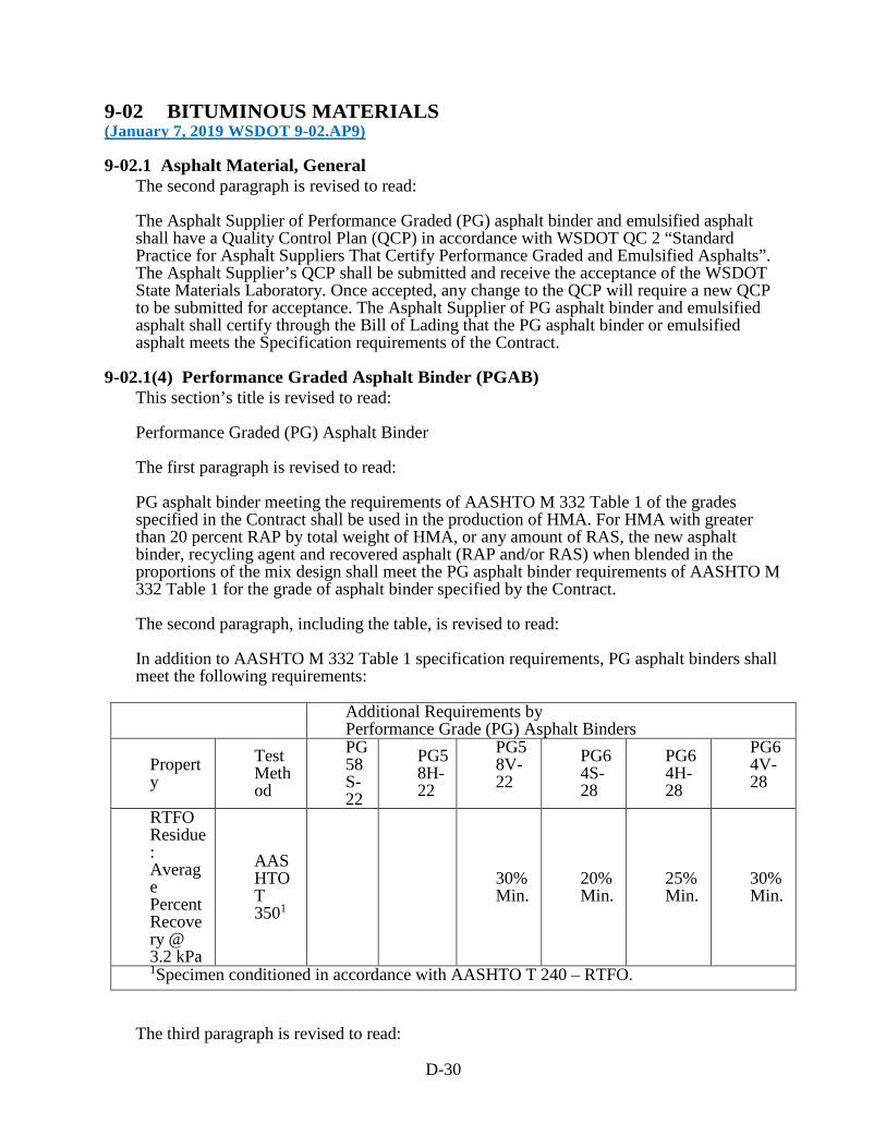
D-30
9-02 BITUMINOUS MATERIALS (January 7, 2019 WSDOT 9-02.AP9)
9-02.1 Asphalt Material, General The second paragraph is revised to read: The Asphalt Supplier of Performance Graded (PG) asphalt binder and emulsified asphalt shall have a Quality Control Plan (QCP) in accordance with WSDOT QC 2 “Standard Practice for Asphalt Suppliers That Certify Performance Graded and Emulsified Asphalts”. The Asphalt Supplier’s QCP shall be submitted and receive the acceptance of the WSDOT State Materials Laboratory. Once accepted, any change to the QCP will require a new QCP to be submitted for acceptance. The Asphalt Supplier of PG asphalt binder and emulsified asphalt shall certify through the Bill of Lading that the PG asphalt binder or emulsified asphalt meets the Specification requirements of the Contract.
9-02.1(4) Performance Graded Asphalt Binder (PGAB) This section’s title is revised to read: Performance Graded (PG) Asphalt Binder The first paragraph is revised to read: PG asphalt binder meeting the requirements of AASHTO M 332 Table 1 of the grades specified in the Contract shall be used in the production of HMA. For HMA with greater than 20 percent RAP by total weight of HMA, or any amount of RAS, the new asphalt binder, recycling agent and recovered asphalt (RAP and/or RAS) when blended in the proportions of the mix design shall meet the PG asphalt binder requirements of AASHTO M 332 Table 1 for the grade of asphalt binder specified by the Contract. The second paragraph, including the table, is revised to read: In addition to AASHTO M 332 Table 1 specification requirements, PG asphalt binders shall meet the following requirements:
Additional Requirements by Performance Grade (PG) Asphalt Binders
Property
Test Method
PG58S-22
PG58H-22
PG58V-22
PG64S-28
PG64H-28
PG64V-28
RTFO Residue: Average Percent Recovery @ 3.2 kPa
AASHTO T 3501
30% Min.
20% Min.
25% Min.
30% Min.
1Specimen conditioned in accordance with AASHTO T 240 – RTFO.
The third paragraph is revised to read:

D-31
The RTFO Jnrdiff and the PAV direct tension specifications of AASHTO M 332 are not required.
9-02.1(6) Cationic Emulsified Asphalt This section is revised to read: Cationic Emulsified Asphalt meeting the requirements of AASHTO M 208 Table 1 of the grades specified in the Contract shall be used.
9-02.5 Warm Mix Asphalt (WMA) Additive This section, including title, is revised to read:
9-02.5 HMA Additive Additives for HMA shall be accepted by the Engineer.
9-03 AGGREGATES (January 7, 2019 WSDOT 9-03.AP9)
9-03.1 Aggregates for Portland Cement Concrete This section’s title is revised to read: Aggregates for Concrete
9-03.1(1) General Requirements The first two sentences of the first paragraph are revised to read: Concrete aggregates shall be manufactured from ledge rock, talus, or sand and gravel in accordance with the provisions of Section 3-01. Reclaimed aggregate may be used if it complies with the specifications for concrete. The second paragraph (up until the colon) is revised to read: Aggregates for concrete shall meet the following test requirements: The second sentence of the second to last paragraph is revised to read: The Contractor shall submit test results according to ASTM C1567 through the Engineer to the State Materials Laboratory that demonstrate that the proposed fly ash when used with the proposed aggregates and cement will control the potential expansion to 0.20 percent or less before the fly ash and aggregate sources may be used in concrete.
9-03.1(2) Fine Aggregate for Portland Cement Concrete This section’s title is revised to read: Fine Aggregate for Concrete
9-03.1(4) Coarse Aggregate for Portland Cement Concrete This section’s title is revised to read: Coarse Aggregate for Concrete

D-32
9-03.1(4)C Grading The first paragraph (up until the colon) is revised to read: Coarse aggregate for concrete when separated by means of laboratory sieves shall conform to one or more of the following gradings as called for elsewhere in these Specifications, Special Provisions, or in the Plans:
9-03.1(5) Combined Aggregate Gradation for Portland Cement Concrete This section’s title is revised to read: Combined Aggregate Gradation for Concrete
9-03.1(5)B Grading In the last paragraph, “WSDOT FOP for WAQTC/AASHTO T 27/T 11” is revised to read “FOP for WAQTC/AASHTO T 27/T 11”.
9-03.2 Aggregate for Job-Mixed Portland Cement Mortar This section’s title is revised to read: Aggregate for Job-Mixed Portland Cement or Blended Hydraulic Cement Mortar The first sentence of the first paragraph is revised to read: Fine aggregate for portland cement or blended hydraulic cement mortar shall consist of sand or other inert materials, or combinations thereof, accepted by the Engineer, having hard, strong, durable particles free from adherent coating.
9-03.4(1) General Requirements The first paragraph (up until the colon) is revised to read: Aggregate for bituminous surface treatment shall be manufactured from ledge rock, talus, or gravel, in accordance with Section 3-01. Aggregates for Bituminous Surface Treatment shall meet the following test requirements:
9-03.8(1) General Requirements The first paragraph (up until the colon) is revised to read: Aggregates for Hot Mix Asphalt shall meet the following test requirements:
9-03.8(2) HMA Test Requirements The two tables in the second paragraph are replaced with the following three tables:
Mix Criteria
HMA Class 3∕8 inch ½ inch ¾ inch 1 inch
Min.
Max.
Min.
Max.
Min.
Max.
Min.
Max.
Voids in Mineral Aggregate (VMA), %
15.0 1
4 13.0 12
.0

D-33
.0
Voids Filled With Asphalt (VFA), % ESAL’s (millions) VFA < 0.3 70 8
0 70
80 70 80
67 80
0.3 to < 3 65 78
65
78 65 78
65 78
≥ 3 73 76
65
75 65 75
65 75
Dust/Asphalt Ratio
0.6
1.6
0.6
1.6
0.6
1.6
0.6
1.6
Test Method ESAL’s (millions) Number of Passes Hamburg Wheel-Track Testing, FOP for AASHTO T 324 Minimum Number of Passes with no Stripping Inflection Point and Maximum Rut Depth of 10mm
< 0.3 10,000
0.3 to < 3 12,500
≥ 3 15,000 Indirect Tensile (IDT) Strength (psi) of Bituminous Materials FOP for ASTM D6931
175 Maximum
ESAL’s
(millions) N initial N design N maximum
% Gmm < 0.3 ≤ 91.5 96.0 ≤ 98.0 0.3 to < 3 ≤ 90.5 96.0 ≤ 98.0 ≥ 3 ≤ 89.0 96.0 ≤ 98.0
Gyratory Compaction (number of gyrations)
< 0.3 6 50 75 0.3 to < 3 7 75 115 > 3 8 100 160
9-03.8(7) HMA Tolerances and Adjustments In the table in item number 1, the fifth row is revised to read: Asphalt binder -0.4% to
0.5% ±0.7%
In the table in item number 1, the following new row is inserted before the last row: Voids in Mineral Aggregate, VMA
-1.5%
9-03.9(1) Ballast The second paragraph (up until the colon) is revised to read: Aggregates for ballast shall meet the following test requirements:

D-34
9-03.14(4) Gravel Borrow for Structural Earth Wall The second sentence of the first paragraph is revised to read: The material shall be substantially free of shale or other soft, poor durability particles, and shall not contain recycled materials, such as glass, shredded tires, concrete rubble, or asphaltic concrete rubble.
9-03.21(1)B Recycled Concrete Aggregate Approval and Acceptance The first sentence of the second paragraph is revised to read: Recycled concrete aggregate may be used as coarse aggregate or blended with coarse aggregate for Commercial Concrete, Class 3000 concrete, or Cement Concrete Pavement. Item number 4 of the second paragraph is revised to read: 4. For Cement Concrete Pavement mix designs using recycled concrete aggregates, the Contractor shall submit evidence that ASR mitigating measures control expansion in accordance with Section 9-03.1(1). This section is supplemented with the following new subsection:
9-03.21(1)B1 Recycled Concrete Aggregate Approval and Acceptance Recycled concrete aggregate may be approved through a three tiered system that consists of the following:
Tier 1 Approval Requirements
Approval of the Reclamation Facility is not required.
Acceptance Requirements
Certification of toxicity characteristics in accordance with Section 9-03.21(1). Field acceptance testing in accordance with Section 3-04.
Approved to provide the following Aggregate Materials: 9-03.10 Aggregate for Gravel Base 9-03.12(1)B Gravel Backfill for Foundations Class B 9-03.12(2) Gravel Backfill for Walls 9-03.12(3) Gravel Backfill for Pipe Zone Bedding 9-03.14(1) Gravel Borrow 9-03.14(2) Select Borrow 9-03.14(2) Select Borrow (greater than 3 feet below subgrade and side slope) 9-03.14(3) Common Borrow 9-03.14(3) Common Borrow (greater than 3 feet below subgrade and side slope) 9-03.17 Foundation Material Class A and Class B 9-03.18 Foundation Material Class C 9-03.19 Bank Run Gravel for Trench Backfill
Tier 2 Approval Requirements
The Reclamation Facility shall have a Quality Control Plan (QCP) in accordance with WSDOT QC 9 “Standard Practice for Approval of Reclamation Facilities of WSDOT Recycled Concrete and Returned Concrete”. The Reclamation Facility’s QCP shall be submitted and approved by the WSDOT State Materials Laboratory. Once accepted, any changes to the QCP will require a new QCP to be submitted for acceptance.

D-35
Evaluation of aggregate source properties (LA Wear and Degradation) for the recycled concrete aggregate is not required.
Acceptance Requirements
Certification of toxicity characteristics in accordance with Section 9-03.21(1), required if requested. Field acceptance testing in accordance with Section 3-04 is required. Provide certification in accordance with WSDOT QC 9 for every lot. A lot shall be no larger than 10,000 tons.
Approved to provide the following Aggregate Materials: Tier 1 aggregate materials 9-03.1 Coarse Aggregate for Commercial Concrete or Concrete class 3000 9-03.9(1) Ballast 9-03.9(2) Permeable Ballast 9-03.9(3) Crushed Surfacing 9-03.12(1)A Gravel Backfill for Foundations Class A
Tier 3 Approval Requirements
The Reclamation Facility shall have a Quality Control Plan (QCP) in accordance with WSDOT QC 10 “Standard Practice for Approval of Reclamation Facilities of Recycled Concrete Aggregates from Stockpiles of Unknown Sources”. The Reclamation Facility’s QCP shall be submitted and approved by the WSDOT State Materials Laboratory. Once accepted, any changes to the QCP will require a new QCP to be submitted for acceptance. Evaluation of aggregate source properties (LA Wear and Degradation) for the recycled concrete aggregate is required.
Acceptance Requirements
Certification of toxicity characteristics in accordance with Section 9-03.21(1) is required. Field acceptance testing in accordance with Section 3-04 is required. Provide certification in accordance with WSDOT QC 10 for every lot. A lot shall be no larger than 10,000 tons
Approved to provide the following Aggregate Materials: Tier 1 aggregate materials 9-03.1 Coarse Aggregate for Commercial Concrete or Concrete class 3000 9-03.9(1) Ballast 9-03.9(2) Permeable Ballast 9-03.9(3) Crushed Surfacing 9-03.12(1)A Gravel Backfill for Foundations Class A
For Reclamation Facilities that do not participate in Tier 2 and Tier 3, approval of recycled concrete aggregate will be in accordance with Section 9-03.21(1), and acceptance will be in accordance with Section 3-04.
9-03.21(1)E Table on Maximum Allowable percent (By Weight) of Recycled Material “Portland Cement” is deleted from the first two rows in the table. The following new row is inserted after the second row:
Coarse Aggregate for Concrete Pavement
9-03.1(4)
0 100 0 0
The first column of the third row is revised to read: Coarse Aggregate for Commercial Concrete and Class 3000 Concrete.
D-36
9-04 JOINT AND CRACK SEALING MATERIALS (January 7, 2019 WSDOT 9-04.AP9)
This section’s title is revised to read: Joint Sealing Materials
9-04.1(2) Premolded Joint Filler for Expansion Joints In this section, each reference to “AASHTO T 42” is revised to read “ASTM D 545”.
9-04.2(1)A1 Hot Poured Sealant for Cement Concrete Pavement This section is supplemented with the following: Hot poured sealant for cement concrete pavement is acceptable for installations in joints where cement concrete pavement abuts a bituminous pavement.
9-04.2(1)A2 Hot Poured Sealant for Bituminous Pavement This section is supplemented with the following: Hot poured sealant for bituminous pavement is acceptable for installations in joints where cement concrete pavement abuts a bituminous pavement.
9-04.2(1)B Sand Slurry for Bituminous Pavement Item number 2 of the first paragraph is revised to read: 2. Two percent portland cement or blended hydraulic cement, and
9-04.3 Joint Mortar The first paragraph is revised to read: Mortar for hand mortared joints shall conform to Section 9-20.4(3) and consist of one part portland cement or blended hydraulic cement, three parts fine sand, and sufficient water to allow proper workability.
9-04.5 Flexible Plastic Gaskets In the table, the Test Method value for Specific Gravity at 77°F is revised to read “ASTM D71”. In the table, the Test Method value for Flash Point COC, F is revised to read “ASTM D93 REV A”. In the table, the Test Method value for Volatile Matter is revised to read “ASTM D6”.
9-05 DRAINAGE STRUCTURES AND CULVERTS (January 7, 2019 WSDOT 9-05.AP9)
9-05.3(1)A End Design and Joints The second sentence of the first paragraph is revised to read: The joints and gasket material shall meet the requirements of ASTM C990.
D-37
9-05.3(1)C Age at Shipment The last sentence of the first paragraph is revised to read: Unless it is tested and accepted at an earlier age, it shall not be considered ready for shipment sooner than 28 days after manufacture when made with Type II portland cement or blended hydraulic cement, nor sooner than 7 days when made with Type III portland cement.
9-05.7(3) Concrete Storm Sewer Pipe Joints The second sentence is revised to read: The joints and gasket material shall meet the requirements of ASTM C990.
9-05.7(4)A Hydrostatic Pressure on Pipes in Straight Alignment The first sentence is revised to read: Hydrostatic pressure tests on pipes in straight alignment shall be made in accordance with the procedure outlined in Section 10 of ASTM C990, except that they shall be performed on an assembly consisting of not less than three nor more than five pipe sections selected from stock by the Engineer and assembled in accordance with standard installation instructions issued by the manufacturer.
9-05.24(1) Polypropylene Culvert Pipe and Storm Sewer Pipe This section is revised to read: Polypropylene culvert and storm sewer pipe shall conform to the following requirements: 1. For dual wall pipe sizes up to 60 inches: ASTM F2881 or AASHTO M 330, Type S or Type D. 2. For double or triple wall pipe sizes up to 60 inches: ASTM F2764. 3. Fittings shall be factory welded, injection molded, or PVC.
9-05.24(2) Polypropylene Sanitary Sewer Pipe This section is revised to read: Polypropylene sanitary sewer pipe shall conform to the following requirements: 1. For pipe sizes up to 60 inches: ASTM F2764. 2. Fittings shall be factory welded, injection molded, or PVC.
9-06 STRUCTURAL STEEL AND RELATED MATERIALS (January 2, 2018 WSDOT 9-06.AP9)
9-06.5 Bolts This section’s title is revised to read:
D-38
Bolts and Rods
9-06.5(4) Anchor Bolts This section, including title, is revised to read:
9-06.5(4) Anchor Bolts and Anchor Rods Anchor bolts and anchor rods shall meet the requirements of ASTM F1554 and, unless otherwise specified, shall be Grade 105 and shall conform to Supplemental Requirements S2, S3, and S4. Nuts for ASTM F1554 Grade 105 black anchor bolts and anchor rods shall conform to ASTM A563, Grade D or DH. Nuts for ASTM F1554 Grade 105 galvanized anchor bolts and anchor rods shall conform to either ASTM A563, Grade DH, or AASHTO M292, Grade 2H, and shall conform to the overtapping, lubrication, and rotational testing requirements in Section 9-06.5(3). Nuts for ASTM F1554 Grade 36 or 55 black or galvanized anchor bolts and anchor rods shall conform to ASTM A563, Grade A or DH. Washers shall conform to ASTM F436. The bolts and rods shall be tested by the manufacturer in accordance with the requirements of the pertinent Specification and as specified in these Specifications. Anchor bolts, anchor rods, nuts, and washers shall be inspected prior to shipping to the project site. The Contractor shall submit to the Engineer for acceptance a Manufacturer’s Certificate of Compliance for the anchor bolts, anchor rods, nuts, and washers, as defined in Section 1-06.3. If the Engineer deems it appropriate, the Contractor shall provide a sample of the anchor bolt, anchor rod, nut, and washer for testing. All bolts, rods, nuts, and washers shall be marked and identified as required in the pertinent Specification.
9-06.18 Metal Bridge Railing The second sentence of the first paragraph is revised to read: Steel used for metal railings, when galvanized after fabrication in accordance with AASHTO M111, shall have a controlled silicon content of either 0.00 to 0.06 percent or 0.15 to 0.25 percent.
9-21 RAISED PAVEMENT MARKERS (RPM) (January 2, 2018 WSDOT 9-21.AP9)
9-21.2 Raised Pavement Markers Type 2 This section’s content is deleted.
9-21.2(1) Physical Properties This section, including title, is revised to read:
9-21.2(1) Standard Raised Pavement Markers Type 2 The marker housing shall contain reflective faces as shown in the Plans to reflect incident light from either a single or opposite directions and meet the requirements of ASTM D 4280 including Flexural strength requirements.

D-39
9-21.2(2) Optical Requirements This section, including title, is revised to read:
9-21.2(2) Abrasion Resistant Raised Markers Type 2 Abrasion Resistant Raised Markers Type 2 shall comply with Section 9-21.2(1) and meet the requirements of ASTM D 4280 with the following additional requirement: The coefficient of luminous intensity of the markers shall be measured after subjecting the entire lens surface to the test described in ASTM D 4280 Section 9.5 using a sand drop apparatus. After the exposure described above, retroreflected values shall not be less than 0.5 times a nominal unblemished sample.
9-21.2(3) Strength Requirements This section is deleted in its entirety.
9-28 SIGNING MATERIALS AND FABRICATION (April 2, 2018 WSDOT 9-28.AP9)
9-28.10 Vacant
9-28.10 Digital Printing Transparent and opaque durable inks used in digital printed sign messages shall be as recommended by the manufacturer. When properly applied, digital printed colors shall have a warranty life of the base retroreflective sign sheeting. Digital applied colors shall present a smooth surface, free from foreign material, and all messages and borders shall be clear and sharp. Digital printed signs shall conform to 70% of the retroreflective minimum values established for its type and color. Digitally printed signs shall meet the daytime color and luminance, and nighttime color requirements of ASTM D 4956. No variations in color or overlapping of colors will be permitted. Digital printed permanent traffic signs shall have an integrated engineered match component clear protective overlay recommended by the sheeting manufacturer applied to the entire face of the sign. On Temporary construction/maintenance signs printed with black ink only, the protective overlay film is optional, as long as the finished sign has a warranty of a minimum of three years from sign sheeting manufacturer. All digital printed traffic control signs shall be an integrated engineered match component system. The integrated engineered match component system shall consist of retroreflective sheeting, durable ink(s), and clear overlay film all from the same manufacturer applied to aluminum substrate conforming to Section 9-28.8. The sign fabricator shall use an approved integrated engineered match component system as listed on the Qualified Products List (QPL). Each approved digital printer shall only use the compatible retroreflective sign sheeting manufacturer’s engineered match component system products. Each retroreflective sign sheeting manufacturer/integrated engineered match component system listed on the QPL shall certify a department approved sign fabricator is approved to operate their compatible digital printer. The sign fabricator shall re-certify annually with the retroreflective sign manufacturer to ensure their digital printer is still meeting manufacturer’s specifications for traffic control signs. Documentation of each re-certification shall be submitted to the QPL Engineer annually
This section, including title, is revised to read:

D-40
9-28.11 Hardware The last paragraph is revised to read: All steel parts shall be galvanized in accordance with AASHTO M111. Steel bolts and related connecting hardware shall be galvanized in accordance with ASTM F 2329.
9-28.14(2) Steel Structures and Posts The first sentence of the third paragraph is revised to read: Anchor rods for sign bridge and cantilever sign structure foundations shall conform to Section 9-06.5(4), including Supplemental Requirement S4 tested at -20°F. In the second sentence of the fourth paragraph, “AASHTO M232” is revised to read “ASTM F 2329”. The first sentence of the fifth paragraph is revised to read: Except as otherwise noted, steel used for sign structures and posts shall have a controlled silicon content of either 0.00 to 0.06 percent or 0.15 to 0.25 percent. The last sentence of the last paragraph is revised to read: If such modifications are contemplated, the Contractor shall submit a Type 2 Working Drawing of the proposed modifications.
9-29 ILLUMINATION, SIGNAL, ELECTRICAL (April 2, 2018 WSDOT 9-29.AP9)
9-29.1 Conduit, Innerduct, and Outerduct This section is supplemented with the following new subsection:
9-29.1(10) Pull Tape Pull tape shall be pre-lubricated polyester pulling tape. The pull tape shall have a minimum width of ½-inch and a minimum tensile strength of 500 pounds. Pull tape may have measurement marks.
9-29.2(1) Junction Boxes The first paragraph is revised to read: For the purposes of this Specification concrete is defined as portland cement or blended hydraulic cement concrete and non-concrete is all others.
9-29.2(1)A2 Non-Concrete Junction Boxes The first paragraph is revised to read: Material for the non-concrete junction boxes shall be of a quality that will provide for a similar life expectancy as portland cement or blended hydraulic cement concrete in a direct burial application.
9-29.2(2)A Standard Duty Cable Vaults and Pull Boxes In the table in the last paragraph, the fourth, fifth and sixth rows are revised to read:

D-41
Slip Resistant Lid ASTM A36 steel Frame ASTM A36 steel Slip Resistant Frame ASTM A36 steel
9-29.6 Light and Signal Standards In the first sentence of the third paragraph, “AASHTO M232” is revised to read “ASTM F 2329”. Item number 2 of the last paragraph is revised to read: 2. The steel light and signal standard fabricator’s shop drawing submittal, including supporting design calculations, submitted as a Type 2E Working Drawing in accordance with Section 8-20.2(1) and the Special Provisions.
9-29.6(1) Steel Light and Signal Standards In the second paragraph, “AASHTO M232” is revised to read “ASTM F 2329”. The first sentence of the last paragraph is revised to read: Steel used for light and signal standards shall have a controlled silicon content of either 0.00 to 0.06 percent or 0.15 to 0.25 percent.
9-29.6(5) Foundation Hardware In the last paragraph, “AASHTO M232” is revised to read “ASTM F 2329”.
9-29.10(1) Conventional Roadway Luminaires This section is revised to read: All conventional roadway luminaires shall meet 3G vibration requirements as described in ANSI C136.31. All luminaires shall have housings fabricated from aluminum. The housing shall be painted flat gray, SAE AMS Standard 595 color chip No. 26280, unless otherwise specified in the Contract. Painted housings shall withstand a 1,000 hour salt spray test as specified in ASTM B117. Each housing shall include a four bolt slip-fitter mount capable of accepting a nominal 2” tenon and adjustable within +/- 5 degrees of the axis of the tenon. The clamping bracket(s) and the cap screws shall not bottom out on the housing bosses when adjusted within the +/- 5 degree range. No part of the slipfitter mounting brackets on the luminaires shall develop a permanent set in excess of 0.2 inch when the cap screws used for mounting are tightened to a torque of 32 foot-pounds. Each luminaire shall include leveling reference points for both transverse and longitudinal adjustment. All luminaires shall include shorting caps when shipped. The caps shall be removed and provided to the Contracting Agency when an alternate control device is required to be installed in the photocell socket. House side shields shall be included when required by the Contract. Order codes shall be modified to the minimum extent necessary to include the option for house side shields. This section is supplemented with the following new subsections:

D-42
9-29.10(1)A High Pressure Sodium (HPS) Conventional Roadway Luminaires HPS conventional roadway luminaires shall meet the following requirements: 1. General shape shall be “cobrahead” style, with flat glass lens and full cutoff optics. 2. Light pattern distribution shall be IES Type III. 3. The reflector of all luminaires shall be of a snap-in design or secured with screws. The reflector shall be polished aluminum or prismatic borosilicate glass. 4. Flat lenses shall be formed from heat resistant, high-impact, molded borosilicate or tempered glass. 5. The lens shall be mounted in a doorframe assembly, which shall be hinged to the luminaire and secured in the closed position to the luminaire by means of an automatic latch. The lens and doorframe assembly, when closed, shall exert pressure against a gasket seat. The lens shall not allow any light output above 90 degrees nadir. Gaskets shall be composed of material capable of withstanding the temperatures involved and shall be securely held in place. 6. The ballast shall be mounted on a separate exterior door, which shall be hinged to the luminaire and secured in the closed position to the luminaire housing by means of an automatic type of latch (a combination hex/slot stainless steel screw fastener may supplement the automatic-type latch). 7. Each luminaire shall be capable of accepting a 150, 200, 250, 310, or 400 watt lamp complete and associated ballast. Lamps shall mount horizontally.
9-29.10(1)B Light Emitting Diode (LED) Conventional Roadway Luminaires LED Conventional Roadway Luminaires are divided into classes based on their equivalent High Pressure Sodium (HPS) luminaires. Current classes are 200W, 250W, 310W, and 400W. LED luminaires are required to be pre-approved in order to verify their photometric output. To be considered for pre-approval, LED luminaires must meet the requirements of this section. LED luminaires shall include a removable access door, with tool-less entry, for access to electronic components and the terminal block. The access door shall be removable, but include positive retention such that it can hang freely without disconnecting from the luminaire housing. LED drivers may be mounted either to the interior of the luminaire housing or to the removable door itself. LED drivers shall be removable for user replacement. All internal modular components shall be connected by means of mechanical plug and socket type quick disconnects. Wire nuts may not be used for any purpose. All external electrical connections to the luminaire shall be made through the terminal block. LED luminaires shall include a 7-pin NEMA photocell receptacle. The LED driver(s) shall be dimmable from ten volts to zero volts. LED output shall have a Correlated Color Temperature (CCT) of 4000K nominal (4000-4300K) and a Color Rendering Index (CRI) of 70 or greater. LED output shall be a minimum of 85% at 75,000 hours at 25 degrees Celsius.
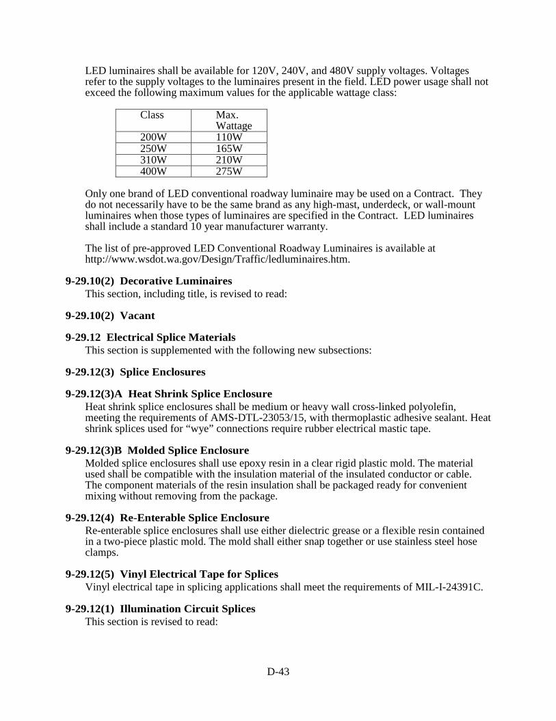
D-43
LED luminaires shall be available for 120V, 240V, and 480V supply voltages. Voltages refer to the supply voltages to the luminaires present in the field. LED power usage shall not exceed the following maximum values for the applicable wattage class:
Class Max. Wattage
200W 110W 250W 165W 310W 210W 400W 275W
Only one brand of LED conventional roadway luminaire may be used on a Contract. They do not necessarily have to be the same brand as any high-mast, underdeck, or wall-mount luminaires when those types of luminaires are specified in the Contract. LED luminaires shall include a standard 10 year manufacturer warranty. The list of pre-approved LED Conventional Roadway Luminaires is available at http://www.wsdot.wa.gov/Design/Traffic/ledluminaires.htm.
9-29.10(2) Decorative Luminaires This section, including title, is revised to read:
9-29.10(2) Vacant
9-29.12 Electrical Splice Materials This section is supplemented with the following new subsections:
9-29.12(3) Splice Enclosures
9-29.12(3)A Heat Shrink Splice Enclosure Heat shrink splice enclosures shall be medium or heavy wall cross-linked polyolefin, meeting the requirements of AMS-DTL-23053/15, with thermoplastic adhesive sealant. Heat shrink splices used for “wye” connections require rubber electrical mastic tape.
9-29.12(3)B Molded Splice Enclosure Molded splice enclosures shall use epoxy resin in a clear rigid plastic mold. The material used shall be compatible with the insulation material of the insulated conductor or cable. The component materials of the resin insulation shall be packaged ready for convenient mixing without removing from the package.
9-29.12(4) Re-Enterable Splice Enclosure Re-enterable splice enclosures shall use either dielectric grease or a flexible resin contained in a two-piece plastic mold. The mold shall either snap together or use stainless steel hose clamps.
9-29.12(5) Vinyl Electrical Tape for Splices Vinyl electrical tape in splicing applications shall meet the requirements of MIL-I-24391C.
9-29.12(1) Illumination Circuit Splices This section is revised to read:

D-44
Underground illumination circuit splices shall be solderless crimped connections capable of securely joining the wires, both mechanically and electrically, as defined in Section 8-20.3(8). Aerial illumination splices shall be solderless crimp connectors or split bolt vice-type connectors.
9-29.12(1)A Heat Shrink Splice Enclosure This section is deleted in its entirety.
9-29.12(1)B Molded Splice Enclosure This section is deleted in its entirety.
9-29.12(2) Traffic Signal Splice Material This section is revised to read: Induction loop splices and magnetometer splices shall use an uninsulated barrel-type crimped connector capable of being soldered.
9-29.16(2)E Painting Signal Heads In the first sentence, “Federal Standard 595” is revised to read “SAE AMS Standard 595”.
9-29.17 Signal Head Mounting Brackets and Fittings In the first paragraph, item number 2 under Stainless Steel is revised to read: 2. Bands or cables for Type N mount.
9-29.20 Pedestrian Signals In item 2C of the second paragraph, “Federal Standard 595” is revised to read “SAE AMS Standard 595”.
9-29.24 Service Cabinets The third sentence of item number 6 is revised to read: The dead front cover shall have cutouts for the entire breaker array, with blank covers where no circuit breakers are installed. Item number 8 is revised to read: 8. Lighting contactors shall meet the requirements of Section 9-29.24(2). The last sentence of item number 10 is revised to read: Dead front panels shall prevent access to any exposed, live components, and shall cover all equipment except for circuit breakers (including blank covers), the photocell test/bypass switch, and the GFCI receptacle.
9-29.24(2) Electrical Circuit Breakers and Contactors This section is revised to read: All circuit breakers shall be bolt-on type, with the RMS-symmetrical interrupting capacity described in this Section. Circuit breakers for 120/240/277 volt circuits shall be rated at 240 or 277 volts, as applicable, with an interrupting capacity of not less than 10,000 amperes.

D-45
Circuit breakers for 480 volt circuits shall be rated at 480 volts, and shall have an interrupting capacity of not less than 14,000 amperes. Lighting contactors shall be rated for tungsten or ballasted (such as sodium vapor, mercury vapor, metal halide, and fluorescent) lamp loads. Contactors for 120/240/277 volt circuits shall be rated at 240 volts maximum line to line voltage, or 277 volts maximum line to neutral voltage, as applicable. Contactors for 480 volt circuits shall be rated at 480 volt maximum line to line voltage.
9-34 PAVEMENT MARKING MATERIAL (January 2, 2018 WSDOT 9-34.AP9)
9-34.2(2) Color Each reference to “Federal Standard 595” is revised to read “SAE AMS Standard 595”.
9-34.3 Plastic In the first sentence of the last paragraph, “Federal Standard 595” is revised to read “SAE AMS Standard 595”.
9-34.3(2) Type B – Pre-Formed Fused Thermoplastic In the last two paragraphs, each reference to “Federal Standard 595” is revised to read “SAE AMS Standard 595”.
9-34.7(1) Requirements The first paragraph is revised to read: Field performance evaluation is required for low VOC solvent-based paint per Section 9-34.2(4), Type A – liquid hot applied thermoplastic per Section 9-34.3(1), Type B – preformed fused thermoplastic per Section 9-34.3(2), Type C – cold applied preformed tape per Section 9-34.3(3), and Type D – liquid applied methyl methacrylate per Section 9-34.3(4). The last paragraph is deleted.
9-34.7(1)C Auto No-Track Time The first paragraph is revised to read: Auto No-Track Time will only be required for low VOC solvent-based paint in accordance with Section 9-34.2(4). The second and third sentences of the second paragraph are deleted.

D-46
SPECIAL PROVISIONS
INTRODUCTION TO THE SPECIAL PROVISIONS (August 14, 2013 APWA GSP)
The work on this project shall be accomplished in accordance with the Standard Specifications for Road, Bridge and Municipal Construction, 2018 edition, as issued by the Washington State Department of Transportation (WSDOT) and the American Public Works Association (APWA), Washington State Chapter (hereafter “Standard Specifications”). The Standard Specifications, as modified or supplemented by the Amendments to the Standard Specifications and these Special Provisions, all of which are made a part of the Contract Documents, shall govern all of the Work. These Special Provisions are made up of both General Special Provisions (GSPs) from various sources, which may have project-specific fill-ins; and project-specific Special Provisions. Each Provision either supplements, modifies, or replaces the comparable Standard Specification, or is a new Provision. The deletion, amendment, alteration, or addition to any subsection or portion of the Standard Specifications is meant to pertain only to that particular portion of the section, and in no way should it be interpreted that the balance of the section does not apply. The project-specific Special Provisions are not labeled as such. The GSPs are labeled under the headers of each GSP, with the effective date of the GSP and its source. For example: (March 8, 2013 APWA GSP) (April 1, 2013 WSDOT GSP) (May 1, 2013 Lacey GSP) Also incorporated into the Contract Documents by reference are: Manual on Uniform Traffic Control Devices for Streets and Highways, currently adopted edition, with Washington State modifications, if any Standard Plans for Road, Bridge and Municipal Construction, WSDOT/APWA, current edition City of Lacey Development Guidelines and Public Works Standards, current edition Contractor shall obtain copies of these publications, at Contractor’s own expense.
DESCRIPTION OF WORK This contract provides for construction on Ruddell Road from 27th Ave SE to Brentwood Drive for a precast modular block retaining wall to include; minor widening with flatwork, stormwater, illumination, landscaping and other work.
1-01 DEFINITIONS AND TERMS
1-01.3 Definitions (January 4, 2016 APWA GSP)
D-47
Delete the heading Completion Dates and the three paragraphs that follow it, and replace them with the following: Dates Bid Opening Date The date on which the Contracting Agency publicly opens and reads the Bids. Award Date The date of the formal decision of the Contracting Agency to accept the lowest responsible and responsive Bidder for the Work. Contract Execution Date The date the Contracting Agency officially binds the Agency to the Contract. Notice to Proceed Date The date stated in the Notice to Proceed on which the Contract time begins. Substantial Completion Date The day the Engineer determines the Contracting Agency has full and unrestricted use and benefit of the facilities, both from the operational and safety standpoint, any remaining traffic disruptions will be rare and brief, and only minor incidental work, replacement of temporary substitute facilities, plant establishment periods, or correction or repair remains for the Physical Completion of the total Contract. Physical Completion Date The day all of the Work is physically completed on the project. All documentation required by the Contract and required by law does not necessarily need to be furnished by the Contractor by this date. Completion Date The day all the Work specified in the Contract is completed and all the obligations of the Contractor under the contract are fulfilled by the Contractor. All documentation required by the Contract and required by law must be furnished by the Contractor before establishment of this date. Final Acceptance Date The date on which the Contracting Agency accepts the Work as complete. Supplement this Section with the following: All references in the Standard Specifications, Amendments, or WSDOT General Special Provisions, to the terms “Department of Transportation”, “Washington State Transportation Commission”, “Commission”, “Secretary of Transportation”, “Secretary”, “Headquarters”, and “State Treasurer” shall be revised to read “Contracting Agency”. All references to the terms “State” or “state” shall be revised to read “Contracting Agency” unless the reference is to an administrative agency of the State of Washington, a State statute or regulation, or the context reasonably indicates otherwise. All references to “State Materials Laboratory” shall be revised to read “Contracting Agency designated location”.

D-48
All references to “final contract voucher certification” shall be interpreted to mean the Contracting Agency form(s) by which final payment is authorized, and final completion and acceptance granted. Additive A supplemental unit of work or group of bid items, identified separately in the Bid Proposal, which may, at the discretion of the Contracting Agency, be awarded in addition to the base bid. Alternate One of two or more units of work or groups of bid items, identified separately in the Bid Proposal, from which the Contracting Agency may make a choice between different methods or material of construction for performing the same work. Business Day A business day is any day from Monday through Friday except holidays as listed in Section 1-08.5. Contract Bond The definition in the Standard Specifications for “Contract Bond” applies to whatever bond form(s) are required by the Contract Documents, which may be a combination of a Payment Bond and a Performance Bond. Contract Documents See definition for “Contract”. Contract Time The period of time established by the terms and conditions of the Contract within which the Work must be physically completed. Notice of Award The written notice from the Contracting Agency to the successful Bidder signifying the Contracting Agency’s acceptance of the Bid Proposal. Notice to Proceed The written notice from the Contracting Agency or Engineer to the Contractor authorizing and directing the Contractor to proceed with the Work and establishing the date on which the Contract time begins. Traffic Both vehicular and non-vehicular traffic, such as pedestrians, bicyclists, wheelchairs, and equestrian traffic.
1-02 BID PROCEDURES AND CONDITIONS
1-02.1 Prequalification of Bidders Delete this Section and replace it with the following:
1-02.1 Qualifications of Bidder (January 24, 2011 APWA GSP)

D-49
Before award of a public works contract, a bidder must meet at least the minimum qualifications of RCW 39.04.350(1) to be considered a responsible bidder and qualified to be awarded a public works project.
1-02.2 Plans and Specifications (June 27, 2011 APWA GSP)
Delete this section and replace it with the following: Information as to where Bid Documents can be obtained or reviewed will be found in the Call for Bids (Advertisement for Bids) for the work. After award of the contract, plans and specifications will be issued to the Contractor at no cost as detailed below: To Prime Contractor No. of Sets Basis of Distribution Reduced plans (11" x 17") 3 Furnished automatically
upon award Contract Provisions 3 Furnished automatically
upon award Large plans (22" x 34") 3 Furnished only upon
request Additional plans and Contract Provisions may be obtained by the Contractor from the source stated in the Call for Bids, at the Contractor’s own expense.
1-02.4 Examination of Plans, Specifications and Site of Work
1-02.4(1) General (August 15, 2016 APWA GSP Option B)
The first sentence of the last paragraph is revised to read: Any prospective Bidder desiring an explanation or interpretation of the Bid Documents, shall request the explanation or interpretation in writing by close of business five business days preceding the bid opening to allow a written reply to reach all prospective Bidders before the submission of their Bids.
1-02.4(2) Subsurface Information (March 8, 2013 APWA GSP)
The second sentence in the first paragraph is revised to read: The Summary of Geotechnical Conditions and the boring logs, if and when included as an appendix to the Special Provisions, shall be considered as part of the Contract.
1-02.5 Proposal Forms (July 31, 2017 APWA GSP)
Delete this section and replace it with the following:
D-50
The Proposal Form will identify the project and its location and describe the work. It will also list estimated quantities, units of measurement, the items of work, and the materials to be furnished at the unit bid prices. The bidder shall complete spaces on the proposal form that call for, but are not limited to, unit prices; extensions; summations; the total bid amount; signatures; date; and, where applicable, retail sales taxes and acknowledgment of addenda; the bidder’s name, address, telephone number, and signature; the bidder’s UDBE/DBE/M/WBE commitment, if applicable; a State of Washington Contractor’s Registration Number; and a Business License Number, if applicable. Bids shall be completed by typing or shall be printed in ink by hand, preferably in black ink. The required certifications are included as part of the Proposal Form. The Contracting Agency reserves the right to arrange the proposal forms with alternates and additives, if such be to the advantage of the Contracting Agency. The bidder shall bid on all alternates and additives set forth in the Proposal Form unless otherwise specified.
1-02.6 Preparation of Proposal (June 20, 2017 APWA GSP)
Supplement the second paragraph with the following: 4. If a minimum bid amount has been established for any item, the unit or lump sum price must equal or exceed the minimum amount stated. 5. Any correction to a bid made by interlineation, alteration, or erasure, shall be initialed by the signer of the bid. Delete the fourth paragraph and replace it with the following: The Bidder shall submit with the Bid a completed Underutilized Disadvantaged Business Enterprise (UDBE) Utilization Certification, when required by the Special Provisions. For each and every UDBE firm listed on the Bidder’s completed Underutilized Disadvantaged Business Enterprise Utilization Certification, the Bidder shall submit written confirmation from that UDBE firm that the UDBE is in agreement with the UDBE participation commitment that the Bidder has made in the Bidder’s completed Underutilized Disadvantaged Business Enterprise Utilization Certification. WSDOT Form 422-031U (Underutilized Disadvantaged Business Enterprise Written Confirmation Document) is to be used for this purpose. Bidder must submit good faith effort documentation with the Underutilized Disadvantaged Business Enterprise Utilization Certification only in the event the bidder’s efforts to solicit sufficient UDBE participation have been unsuccessful. Directions for delivery of the Underutilized Disadvantaged Business Enterprise Written Confirmation Documents and Underutilized Disadvantaged Business Enterprise Good Faith Effort documentation are included in Sections 1-02.9 Delete the last paragraph, and replace it with the following: The Bidder shall make no stipulation on the Bid Form, nor qualify the bid in any manner. A bid by a corporation shall be executed in the corporate name, by the president or a vice president (or other corporate officer accompanied by evidence of authority to sign). A bid by a partnership shall be executed in the partnership name, and signed by a partner. A copy of the partnership agreement shall be submitted with the Bid Form if any UDBE requirements are to be satisfied through such an agreement.

D-51
A bid by a joint venture shall be executed in the joint venture name and signed by a member of the joint venture. A copy of the joint venture agreement shall be submitted with the Bid Form if any UDBE requirements are to be satisfied through such an agreement.
1-02.6 Preparation of Proposal (April 6, 2020 Lacey)
The bid proposal for this contract requires the Bidder to bid additives as part of the bid. As such the Bidder is required to submit a Base Bid and a bid for the Additive. The Bid Proposal includes the following: 1. Base Bid (Schedule A) a. The Base Bid shall include constructing all items included in the Proposal except those items contained in the Additives. 2. Additive(s) (Schedule B) a. Additive To be considered responsive the Bidder shall submit a price on each and every Bid item include in the Base Bid and all Additives. The successful Bidder will be the Bidder submitting the Lowest Total Bid of the Base Bid and the alternative(s) The Contracting Agency may, at their discretion, award a Contract for the Base Bid, without any additional Additive(s), in the event that all Bids exceed the available funds. In any case, the award will be subject to the requirements of Section 1-03. The sum of the schedule(s) selected by the Contracting Agency will fix the awarded contract price and the amount of the contract bond.
1-02.7 Bid Deposit (March 8, 2013 APWA GSP)
Supplement this section with the following: Bid bonds shall contain the following:
1. Contracting Agency-assigned number for the project; 2. Name of the project; 3. The Contracting Agency named as obligee; 4. The amount of the bid bond stated either as a dollar figure or as a percentage which
represents five percent of the maximum bid amount that could be awarded; 5. Signature of the bidder’s officer empowered to sign official statements. The signature of
the person authorized to submit the bid should agree with the signature on the bond, and the title of the person must accompany the said signature;
6. The signature of the surety’s officer empowered to sign the bond and the power of attorney.
If so stated in the Contract Provisions, bidder must use the bond form included in the Contract Provisions. If so stated in the Contract Provisions, cash will not be accepted for a bid deposit.

D-52
1-02.9 Delivery of Proposal (July 18, 2018 APWA GSP Option B)
Delete this section and replace it with the following: Each Proposal shall be submitted in a sealed envelope, with the Project Name and Project Number as stated in the Call for Bids clearly marked on the outside of the envelope, or as otherwise required in the Bid Documents, to ensure proper handling and delivery. To be considered responsive on a FHWA-funded project, the Bidder may be required to submit the following items, as required by Section 1-02.6: • UDBE Written Confirmation Document from each UDBE firm listed on the Bidder’s completed UDBE Utilization Certification (WSDOT 272-056U); • Good Faith Effort (GFE) Documentation These documents, if applicable, shall be received either with the Bid Proposal or as a Supplement to the Bid. The documents shall be received no later than 24 hours (not including Saturdays, Sundays and Holidays) after the time for delivery of the Bid Proposal. If submitted after the Bid Proposal is due, the document(s) shall be submitted as follows: 1. In a sealed envelope labeled the same as for the Proposal, with “Supplemental Information” added, or 3. By e-mail to the following e-mail address: [email protected] All other information required to be submitted with the Bid Proposal must be submitted with the Bid Proposal itself, at the time stated in the Call for Bids. The Contracting Agency will not open or consider any Bid Proposal that is received after the time specified in the Call for Bids for receipt of Bid Proposals, or received in a location other than that specified in the Call for Bids. The Contracting Agency will not open or consider any “Supplemental Information” (UDBE confirmations or GFE documentation) that is received after the time specified above, or received in a location other than that specified in the Call for Bids.
1-02.10 Withdrawing, Revising, or Supplementing Proposal (July 23, 2015 APWA GSP)
Delete this section in its entirety, and replace it with the following: After submitting a physical Bid Proposal to the Contracting Agency, the Bidder may withdraw, revise, or supplement it if: 1. The Bidder submits a written request signed by an authorized person and physically delivers it to the place designated for receipt of Bid Proposals, and 2. The Contracting Agency receives the request before the time set for receipt of Bid Proposals, and 3. The revised or supplemented Bid Proposal (if any) is received by the Contracting Agency before the time set for receipt of Bid Proposals. If the Bidder’s request to withdraw, revise, or supplement its Bid Proposal is received before the time set for receipt of Bid Proposals, the Contracting Agency will return the unopened
D-53
Proposal package to the Bidder. The Bidder must then submit the revised or supplemented package in its entirety. If the Bidder does not submit a revised or supplemented package, then its bid shall be considered withdrawn. Late revised or supplemented Bid Proposals or late withdrawal requests will be date recorded by the Contracting Agency and returned unopened. Mailed, Emailed, or faxed requests to withdraw, revise, or supplement a Bid Proposal are not acceptable.
1-02.13 Irregular Proposals (June 20, 2017 APWA GSP)
Delete this section and replace it with the following: 1. A Proposal will be considered irregular and will be rejected if: a. The Bidder is not prequalified when so required; b. The authorized Proposal form furnished by the Contracting Agency is not used or is altered; c. The completed Proposal form contains any unauthorized additions, deletions, alternate Bids, or conditions; d. The Bidder adds provisions reserving the right to reject or accept the award, or enter into the Contract; e. A price per unit cannot be determined from the Bid Proposal; f. The Proposal form is not properly executed; g. The Bidder fails to submit or properly complete a Subcontractor list, if applicable, as required in Section 1-02.6; h. The Bidder fails to submit or properly complete an Underutilized Disadvantaged Business Enterprise Certification, if applicable, as required in Section 1-02.6; i. The Bidder fails to submit written confirmation from each UDBE firm listed on the Bidder’s completed UDBE Utilization Certification that they are in agreement with the bidder’s UDBE participation commitment, if applicable, as required in Section 1-02.6, or if the written confirmation that is submitted fails to meet the requirements of the Special Provisions; j The Bidder fails to submit UDBE Good Faith Effort documentation, if applicable, as required in Section 1-02.6, or if the documentation that is submitted fails to demonstrate that a Good Faith Effort to meet the Condition of Award was made; k. The Bid Proposal does not constitute a definite and unqualified offer to meet the material terms of the Bid invitation; or l. More than one Proposal is submitted for the same project from a Bidder under the same or different names. 2. A Proposal may be considered irregular and may be rejected if: a. The Proposal does not include a unit price for every Bid item; b. Any of the unit prices are excessively unbalanced (either above or below the amount of a reasonable Bid) to the potential detriment of the Contracting Agency; c. Receipt of Addenda is not acknowledged; d. A member of a joint venture or partnership and the joint venture or partnership submit Proposals for the same project (in such an instance, both Bids may be rejected); or e. If Proposal form entries are not made in ink.
1-02.14 Disqualification of Bidders (May 17, 2018 APWA GSP Option A)
Delete this Section and replace it with the following:
D-54
A Bidder will be deemed not responsible if the Bidder does not meet the mandatory bidder responsibility criteria in RCW 39.04.350(1), as amended. The Contracting Agency will verify that the Bidder meets the mandatory bidder responsibility criteria in RCW 39.04.350(1). To assess bidder responsibility, the Contracting Agency reserves the right to request documentation as needed from the Bidder and third parties concerning the Bidder’s compliance with the mandatory bidder responsibility criteria. If the Contracting Agency determines the Bidder does not meet the mandatory bidder responsibility criteria in RCW 39.04.350(1) and is therefore not a responsible Bidder, the Contracting Agency shall notify the Bidder in writing, with the reasons for its determination. If the Bidder disagrees with this determination, it may appeal the determination within two (2) business days of the Contracting Agency’s determination by presenting its appeal and any additional information to the Contracting Agency. The Contracting Agency will consider the appeal and any additional information before issuing its final determination. If the final determination affirms that the Bidder is not responsible, the Contracting Agency will not execute a contract with any other Bidder until at least two business days after the Bidder determined to be not responsible has received the Contracting Agency’s final determination..
1-02.15 Pre-Award Information August 14, 2013 APWA GSP)
Revise this section to read: Before awarding any contract, the Contracting Agency may require one or more of these items or actions of the apparent lowest responsible bidder:
1. A complete statement of the origin, composition, and manufacture of any or all materials to be used,
2. Samples of these materials for quality and fitness tests, 3. A progress schedule (in a form the Contracting Agency requires) showing the order of
and time required for the various phases of the work, 4. A breakdown of costs assigned to any bid item, 5. Attendance at a conference with the Engineer or representatives of the Engineer, 6. Obtain, and furnish a copy of, a business license to do business in the city or county
where the work is located. 7. Any other information or action taken that is deemed necessary to ensure that the bidder
is the lowest responsible bidder.
1-03 AWARD AND EXECUTION OF CONTRACT
1-03.3 Execution of Contract (October 1, 2005 APWA GSP)
Revise this section to read: Copies of the Contract Provisions, including the unsigned Form of Contract, will be available for signature by the successful bidder on the first business day following award.
D-55
The number of copies to be executed by the Contractor will be determined by the Contracting Agency. Within 10 calendar days after the award date, the successful bidder shall return the signed Contracting Agency-prepared contract, an insurance certification as required by Section 1-07.18, and a satisfactory bond as required by law and Section 1-03.4. Before execution of the contract by the Contracting Agency, the successful bidder shall provide any pre-award information the Contracting Agency may require under Section 1-02.15. Until the Contracting Agency executes a contract, no proposal shall bind the Contracting Agency nor shall any work begin within the project limits or within Contracting Agency-furnished sites. The Contractor shall bear all risks for any work begun outside such areas and for any materials ordered before the contract is executed by the Contracting Agency. If the bidder experiences circumstances beyond their control that prevents return of the contract documents within the calendar days after the award date stated above, the Contracting Agency may grant up to a maximum of 10 additional calendar days for return of the documents, provided the Contracting Agency deems the circumstances warrant it.
1-03.3 Execution of Contract (April 2, 2018 Lacey)
Section 1-03.3 is supplemented with the following: The Contract will not be executed until the Contractor completes sections I, III, and VIII of the Transfer of Coverage for the Construction Stormwater General Permit and returns the form to the Contracting Agency.
1-03.4 Contract Bond (July 23, 2015 APWA GSP)
Delete the first paragraph and replace it with the following: The successful bidder shall provide executed payment and performance bond(s) for the full contract amount. The bond may be a combined payment and performance bond; or be separate payment and performance bonds. In the case of separate payment and performance bonds, each shall be for the full contract amount. The bond(s) shall:
1. Be on Contracting Agency-furnished form(s); 2. Be signed by an approved surety (or sureties) that:
a) Is registered with the Washington State Insurance Commissioner, and b) Appears on the current Authorized Insurance List in the State of Washington
published by the Office of the Insurance Commissioner, 3. Guarantee that the Contractor will perform and comply with all obligations, duties, and
conditions under the Contract, including but not limited to the duty and obligation to indemnify, defend, and protect the Contracting Agency against all losses and claims related directly or indirectly from any failure: a) Of the Contractor (or any of the employees, subcontractors, or lower tier
subcontractors of the Contractor) to faithfully perform and comply with all contract obligations, conditions, and duties, or
b) Of the Contractor (or the subcontractors or lower tier subcontractors of the Contractor) to pay all laborers, mechanics, subcontractors, lower tier subcontractors,
D-56
material person, or any other person who provides supplies or provisions for carrying out the work;
4. Be conditioned upon the payment of taxes, increases, and penalties incurred on the project under titles 50, 51, and 82 RCW; and
5. Be accompanied by a power of attorney for the Surety’s officer empowered to sign the bond; and
6. Be signed by an officer of the Contractor empowered to sign official statements (sole proprietor or partner). If the Contractor is a corporation, the bond(s) must be signed by the president or vice president, unless accompanied by written proof of the authority of the individual signing the bond(s) to bind the corporation (i.e., corporate resolution, power of attorney, or a letter to such effect signed by the president or vice president).
1-03.7 Judicial Review (November 30, 2018 APWA GSP)
Delete this section and replace it with the following: Any decision made by the Contracting Agency regarding the Award and execution of the Contract or Bid rejection shall be conclusive subject to the scope of judicial review permitted under Washington Law. Such review, if any, shall be timely filed in the Superior Court of the county where the Contracting Agency headquarters is located, provided that where an action is asserted against a county, RCW 36.01.050 shall control venue and jurisdiction.
1-04 SCOPE OF THE WORK
1-04.4(1) Minor Changes (May 30, 2019 APWA GSP)
Delete the first paragraph and replace it with the following: Payments or credits for changes amounting to $15,000 or less may be made under the Bid item “Minor Change”. At the discretion of the Contracting Agency, this procedure for Minor Changes may be used in lieu of the more formal procedure as outlined in Section 1-04.4, Changes. All “Minor Change” work will be within the scope of the Contract Work and will not change Contract Time.
1-04.2 Coordination of Contract Documents, Plans, Special Provisions, Specifications, and Addenda (April 30, 2015 Lacey GSP)
Revise the second paragraph to read: Any inconsistency in the parts of the contract shall be resolved by following this order of precedence (e.g., 1 presiding over 2, 2 presiding over 3, 3 over 4, and so forth):
1. Contract Form, 2. Addenda (if any), 3. Proposal Form, 4. Special Provisions, 5. Technical Specifications, if included, 6. Contract Plans,
D-57
7. Amendments to the Standard Specifications, 8. WSDOT Standard Specifications for Road, Bridge, and Municipal Construction, 9. City of Lacey Development Guidelines and Public Works Standards, and 10. WSDOT Standard Plans for Road, Bridge and Municipal Construction
1-04.6 Variation in Estimated Quantities (May 25, 2006 APWA GSP)
Supplement this Section with the following: The quantities for “Utility Potholing”, “Controlled Density Fill”, “Imported Pipe Bedding” and “Bank Run Gravel for Trench Backfill” have been entered into the Proposal only to provide a common proposal for bidders. Actual quantities will be determined in the field as the work progresses, and will be paid at the original bid price, regardless of final quantity. These bid items shall not be subject to the provisions of 1-04.6 of the Standard Specifications.
1-04.6 Variations in Estimated Quantities (July 23, 2015 APWA GSP Option B)
Revise the first paragraph to read: Payment to the Contractor will be made only for the actual quantities of Work performed and accepted in conformance with the Contract. When the accepted quantity of Work performed under a unit item varies from the original Proposal quantity, payment will be at the unit Contract price for all Work unless the total accepted quantity of any Contract item, adjusted to exclude added or deleted amounts included in change orders accepted by both parties, increases or decreases by more than 25 percent from the original Proposal quantity, and if the total extended bid price for that item at time of award is equal to or greater than 10 percent of the total contract price at time of award. In that case, payment for contract work may be adjusted as described herein:
1-05 CONTROL OF WORK
1-05.4 Conformity With and Deviations from Plans and Stakes Supplement this section with the following:
Roadway and Utility Surveys (July 23, 2015 APWA GSP, Option 1)
The Engineer shall furnish to the Contractor one time only all principal lines, grades, and measurements the Engineer deems necessary for completion of the work. These shall generally consist of one initial set of:
1. Slope stakes for establishing grading; 2. Curb grade stakes; 3. Centerline finish grade stakes for pavement sections wider than 25 feet; and 4. Offset points to establish line and grade for underground utilities such as water, sewers,
and storm drains.

D-58
On alley construction projects with minor grade changes, the Engineer shall provide only offset hubs on one side of the alley to establish the alignment and grade.
1-05.4(2) Survey Control and Electronic Files (August 10, 2010 Lacey GSP)
Add the following new section: The Contractor shall re-establish the survey control used in design by using existing survey monuments and other control points as provided by the City. When requested by the Contractor, the City will provide an electronic version of the construction plans (drawings), for use by the Contractor at the Contractor’s own risk. In all cases, the approved paper construction plans are the official contract documents. If the Contractor wishes to use the electronic version of the construction plans for the purposes of providing surveying of the proposed improvements, it shall be the Contractor’s responsibility to verify that any coordinates used from the electronic file match the station and offset location given in the contract construction plans. Construction plans are diagrammatic in nature. The coordinate locations of the various graphic elements within the electronic files may not necessarily be precisely shown with respect to their coordinate position. In all cases, the location callouts in the contract construction plans shall govern.
1-05.6 Inspection of Work and Materials (December 19, 2019 Lacey GSP)
Supplement this section with the following: The City has hired a firm to do testing for this job on items including but not limited to aggregate gradation and compaction, HMA aggregate gradation, HMA compaction, rebar inspection, concrete strength, and other special inspections and testing as needed. The City will pay for this testing, however the Contractor is responsible for coordinating with the testing firm, and scheduling testing at least 48 hours in advance. Any inspections, tests, measurements or other actions by the testing firm serve only one purpose: to assure the Engineer that the Work and materials comply with the Contract terms. Such work by the testing firm shall not relieve the Contractor from doing any Contract-assigned Work or from determining whether Contract requirements are being met. The Contractor shall correct any substandard Work or materials. The Engineer will reject unsuitable Work or materials even though paid for in a progress estimate. Any fees associated with testing due to lack of 48 hour notice to the testing firm will be paid by the Contractor. It is the Contractor’s responsibility to notify the testing firm of any schedule changes or cancelation of work. If the Contractor fails to notify the testing firm of schedule changes as required by the testing firm the Contractor will pay the invoice for the testing firm for the late cancellation. If work is cancelled on the day of the work due to weather, the City will pay for the invoice for the testing firm for that day’s late cancellation.
1-05.7 Removal of Defective and Unauthorized Work (October 1, 2005 APWA GSP)
Supplement this section with the following: If the Contractor fails to remedy defective or unauthorized work within the time specified in a written notice from the Engineer, or fails to perform any part of the work required by the

D-59
Contract Documents, the Engineer may correct and remedy such work as may be identified in the written notice, with Contracting Agency forces or by such other means as the Contracting Agency may deem necessary. If the Contractor fails to comply with a written order to remedy what the Engineer determines to be an emergency situation, the Engineer may have the defective and unauthorized work corrected immediately, have the rejected work removed and replaced, or have work the Contractor refuses to perform completed by using Contracting Agency or other forces. An emergency situation is any situation when, in the opinion of the Engineer, a delay in its remedy could be potentially unsafe, or might cause serious risk of loss or damage to the public. Direct or indirect costs incurred by the Contracting Agency attributable to correcting and remedying defective or unauthorized work, or work the Contractor failed or refused to perform, shall be paid by the Contractor. Payment will be deducted by the Engineer from monies due, or to become due, the Contractor. Such direct and indirect costs shall include in particular, but without limitation, compensation for additional professional services required, and costs for repair and replacement of work of others destroyed or damaged by correction, removal, or replacement of the Contractor’s unauthorized work. No adjustment in contract time or compensation will be allowed because of the delay in the performance of the work attributable to the exercise of the Contracting Agency’s rights provided by this Section. The rights exercised under the provisions of this section shall not diminish the Contracting Agency’s right to pursue any other avenue for additional remedy or damages with respect to the Contractor’s failure to perform the work as required.
1-05.11 Final Inspections and Operational Testing (October 1, 2005 APWA GSP)
Delete this section and replace it with the following:
1-05.11(1) Substantial Completion Date When the Contractor considers the work to be substantially complete, the Contractor shall so notify the Engineer and request the Engineer establish the Substantial Completion Date. The Contractor’s request shall list the specific items of work that remain to be completed in order to reach physical completion. The Engineer will schedule an inspection of the work with the Contractor to determine the status of completion. The Engineer may also establish the Substantial Completion Date unilaterally. If, after this inspection, the Engineer concurs with the Contractor that the work is substantially complete and ready for its intended use, the Engineer, by written notice to the Contractor, will set the Substantial Completion Date. If, after this inspection the Engineer does not consider the work substantially complete and ready for its intended use, the Engineer will, by written notice, so notify the Contractor giving the reasons therefore. Upon receipt of written notice concurring in or denying substantial completion, whichever is applicable, the Contractor shall pursue vigorously, diligently and without unauthorized interruption, the work necessary to reach Substantial and Physical Completion. The Contractor shall provide the Engineer with a revised schedule indicating when the Contractor expects to reach substantial and physical completion of the work.

D-60
The above process shall be repeated until the Engineer establishes the Substantial Completion Date and the Contractor considers the work physically complete and ready for final inspection.
1-05.11(2) Final Inspection and Physical Completion Date When the Contractor considers the work physically complete and ready for final inspection, the Contractor by written notice, shall request the Engineer to schedule a final inspection. The Engineer will set a date for final inspection. The Engineer and the Contractor will then make a final inspection and the Engineer will notify the Contractor in writing of all particulars in which the final inspection reveals the work incomplete or unacceptable. The Contractor shall immediately take such corrective measures as are necessary to remedy the listed deficiencies. Corrective work shall be pursued vigorously, diligently, and without interruption until physical completion of the listed deficiencies. This process will continue until the Engineer is satisfied the listed deficiencies have been corrected. If action to correct the listed deficiencies is not initiated within 7 days after receipt of the written notice listing the deficiencies, the Engineer may, upon written notice to the Contractor, take whatever steps are necessary to correct those deficiencies pursuant to Section 1-05.7. The Contractor will not be allowed an extension of contract time because of a delay in the performance of the work attributable to the exercise of the Engineer’s right hereunder. Upon correction of all deficiencies, the Engineer will notify the Contractor and the Contracting Agency, in writing, of the date upon which the work was considered physically complete. That date shall constitute the Physical Completion Date of the contract, but shall not imply acceptance of the work or that all the obligations of the Contractor under the contract have been fulfilled.
1-05.11(3) Operational Testing It is the intent of the Contracting Agency to have at the Physical Completion Date a complete and operable system. Therefore when the work involves the installation of machinery or other mechanical equipment; street lighting, electrical distribution or signal systems; irrigation systems; buildings; or other similar work it may be desirable for the Engineer to have the Contractor operate and test the work for a period of time after final inspection but prior to the physical completion date. Whenever items of work are listed in the Contract Provisions for operational testing they shall be fully tested under operating conditions for the time period specified to ensure their acceptability prior to the Physical Completion Date. During and following the test period, the Contractor shall correct any items of workmanship, materials, or equipment which prove faulty, or that are not in first class operating condition. Equipment, electrical controls, meters, or other devices and equipment to be tested during this period shall be tested under the observation of the Engineer, so that the Engineer may determine their suitability for the purpose for which they were installed. The Physical Completion Date cannot be established until testing and corrections have been completed to the satisfaction of the Engineer. The costs for power, gas, labor, material, supplies, and everything else needed to successfully complete operational testing, shall be included in the unit contract prices related to the system being tested, unless specifically set forth otherwise in the proposal.

D-61
Operational and test periods, when required by the Engineer, shall not affect a manufacturer’s guaranties or warranties furnished under the terms of the contract.
1-05.12(1) One-Year Guarantee Period (March 8, 2013 APWA GSP)
Add the following new section: The Contractor shall return to the project and repair or replace all defects in workmanship and material discovered within one year after Final Acceptance of the Work. The Contractor shall start work to remedy any such defects within 7 calendar days of receiving Contracting Agency’s written notice of a defect, and shall complete such work within the time stated in the Contracting Agency’s notice. In case of an emergency, where damage may result from delay or where loss of services may result, such corrections may be made by the Contracting Agency’s own forces or another contractor, in which case the cost of corrections shall be paid by the Contractor. In the event the Contractor does not accomplish corrections within the time specified, the work will be otherwise accomplished and the cost of same shall be paid by the Contractor. When corrections of defects are made, the Contractor shall then be responsible for correcting all defects in workmanship and materials in the corrected work for one year after acceptance of the corrections by Contracting Agency. This guarantee is supplemental to and does not limit or affect the requirements that the Contractor’s work comply with the requirements of the Contract or any other legal rights or remedies of the Contracting Agency.
1-05.14 Cooperation with Other Contractors (August 3, 2015 Lacey GSP)
Supplement this section with the following: The Contractor shall coordinate residential refuse and recycling pick-up with Pacific Disposal (360) 923-0111. Construction activities shall be planned so that there is no interruption of services.
1-05.15 Method of Serving Notices (March 25, 2009 APWA GSP)
Revise the second paragraph to read: All correspondence from the Contractor shall be directed to the Project Engineer. All correspondence from the Contractor constituting any notification, notice of protest, notice of dispute, or other correspondence constituting notification required to be furnished under the Contract, must be in paper format, hand delivered or sent via mail delivery service to the Project Engineer's office. Electronic copies such as e-mails or electronically delivered copies of correspondence will not constitute such notice and will not comply with the requirements of the Contract.
1-05.16 Water and Power (October 1, 2005 APWA GSP)

D-62
Add the following new section: The Contractor shall make necessary arrangements, and shall bear the costs for power and water necessary for the performance of the work, unless the contract includes power and water as a pay item.
1-05.18 Record Drawings (April 2, 2018 Lacey GSP Option B)
Add the following new section: The Contractor shall maintain one set of full size plans for Record Drawings, updated with clear and accurate red-lined field revisions on a daily basis, and within 2 business days after receipt of information that a change in Work has occurred. The Contractor shall not conceal any work until the required information is recorded. This Record Drawing set shall be used for this purpose alone, shall be kept separate from other Plan sheets, and shall be clearly marked as Record Drawings. These Record Drawings shall be kept on site at the Contractor’s field office, and shall be available for review by the Contracting Agency at all times. The Contractor shall bring the Record Drawings to each progress meeting for review. The preparation and upkeep of the Record Drawings is to be the assigned responsibility of a single, experienced, and qualified individual. The quality of the Record Drawings, in terms of accuracy, clarity, and completeness, is to be adequate to allow the Contracting Agency to modify the computer-aided drafting (CAD) Contract Drawings to produce a complete set of Record Drawings for the Contracting Agency without further investigative effort by the Contracting Agency. The Record Drawing markups shall document all changes in the Work, both concealed and visible. Items that must be shown on the markups include but are not limited to: Actual dimensions, arrangement, and materials used when different than shown in the Plans. Changes made by Change Order or Field Order. Changes made by the Contractor. Accurate locations of storm sewer, sanitary sewer, water mains and other water appurtenances, structures, conduits, light standards, vaults, width of roadways, sidewalks, landscaping areas, building footprints, channelization and pavement markings, etc. Include pipe invert elevations, top of castings (manholes, inlets, etc.). If the Contract calls for the Contracting Agency to do all surveying and staking, the Contracting Agency will provide the elevations at the tolerances the Contracting Agency requires for the Record Drawings. When the Contract calls for the Contractor to do the surveying/staking, the applicable tolerance limits include, but are not limited to the following: Vertical Horizontal As-built sanitary & storm invert and grate elevations
± 0.01 foot ± 0.01 foot
As-built monumentation ± 0.01 foot ± 0.01 foot
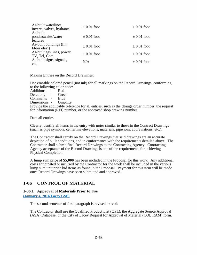
D-63
As-built waterlines, inverts, valves, hydrants ± 0.01 foot ± 0.01 foot As-built ponds/swales/water features
± 0.01 foot ± 0.01 foot
As-built buildings (fin. Floor elev.) ± 0.01 foot ± 0.01 foot As-built gas lines, power, TV, Tel, Com ± 0.01 foot ± 0.01 foot As-built signs, signals, etc. N/A ± 0.01 foot
Making Entries on the Record Drawings: Use erasable colored pencil (not ink) for all markings on the Record Drawings, conforming to the following color code: Additions - Red Deletions - Green Comments - Blue Dimensions - Graphite Provide the applicable reference for all entries, such as the change order number, the request for information (RFI) number, or the approved shop drawing number. Date all entries. Clearly identify all items in the entry with notes similar to those in the Contract Drawings (such as pipe symbols, centerline elevations, materials, pipe joint abbreviations, etc.). The Contractor shall certify on the Record Drawings that said drawings are an accurate depiction of built conditions, and in conformance with the requirements detailed above. The Contractor shall submit final Record Drawings to the Contracting Agency. Contracting Agency acceptance of the Record Drawings is one of the requirements for achieving Physical Completion. A lump sum price of $5,000 has been included in the Proposal for this work. Any additional costs anticipated or incurred by the Contractor for the work shall be included in the various lump sum unit price bid items as found in the Proposal. Payment for this item will be made once Record Drawings have been submitted and approved.
1-06 CONTROL OF MATERIAL
1-06.1 Approval of Materials Prior to Use (January 4, 2016 Lacey GSP)
The second sentence of first paragraph is revised to read: The Contractor shall use the Qualified Product List (QPL), the Aggregate Source Approval (ASA) Database, or the City of Lacey Request for Approval of Material (COL RAM) form.

D-64
1-06.1(2) Request for Approval of Material (RAM) The first paragraph is revised to read: The COL RAM shall be used with all submittals. The COL RAM shall be prepared by the Contractor in accordance with the instructions and submitted to the engineer for approval before the material is incorporated into the Work. Supplement this section with the following: The Contractor shall submit sufficient information that describes the materials proposed as defined and described in these specifications and plans within 20 working days following the Notice to Proceed. The City of Lacey has identified the following items as long lead items. 1. Street Light Pole and Heads Long lead items shall be submitted within 10 working days of Notice to Proceed. The list above may not include all long lead items. The contractor is responsible for identifying all items and shall notify the Engineer of any additional items. The Contractor shall submit one electronic of catalog cuts, shop drawings, and a material testing sample, as required for all items to be used in this contract for approval. The Contractor shall circle or highlight products and materials that are specific to this project, and cross out items that are not for this project. All items not in exact compliance with the specifications must be noted as a change. The Contractor shall include an explanation, product specifications, sample articles, and any other items that will aid the Engineer in approving an item not in exact accordance with the specifications. All submittals shall be submitted in Adobe Acrobat format and submittals that exceed 10 pages shall include a table of contents. Submittals that are not submitted in the format outlined may be rejected outright and the Contractor is required to resubmit in the correct format. The form and the submittal shall be sent in the same e-mail. Submittals that exceed 10 MB shall either be provided on a CD, a flash drive or via an internet link. The Engineer will review submittals within 10 working days. The Contractor may request additional working days if approval or disapproval is not received in 10 working days. The Contractor may not request additional working days for failure to submit sufficient information to approve an item, or for rejection of an item not in accordance with the specifications. Resubmittals shall be submitted within 5 working days from City’s transmittal, to the contractor, of the Engineer reviewed submittal. If the submittal is “Rejected”, the contractor shall resubmit the entire submittal. If the submittal is marked “Revise and Resubmit”, the contractor shall submit items that are identified in the Engineer’s comments. Any material purchased or labor performed prior to such approval shall be at the Contractor's risk. The Contractor must receive all material approvals before the materials will be allowed on the project.
D-65
1-06.6 Recycled Materials (January 4, 2016 APWA GSP)
Delete this section, including its subsections, and replace it with the following: The Contractor shall make their best effort to utilize recycled materials in the construction of the project. Approval of such material use shall be as detailed elsewhere in the Standard Specifications. Prior to Physical Completion the Contractor shall report the quantity of recycled materials that were utilized in the construction of the project for each of the items listed in Section 9-03.21. The report shall include hot mix asphalt, recycled concrete aggregate, recycled glass, steel furnace slag and other recycled materials (e.g. utilization of on-site material and aggregates from concrete returned to the supplier). The Contractor’s report shall be provided on DOT form 350-075 Recycled Materials Reporting.
1-07 LEGAL RELATIONS AND RESPONSIBILITIES TO THE PUBLIC
1-07.1 Laws to be Observed (October 1, 2005 APWA GSP)
Supplement this section with the following: In cases of conflict between different safety regulations, the more stringent regulation shall apply. The Washington State Department of Labor and Industries shall be the sole and paramount administrative agency responsible for the administration of the provisions of the Washington Industrial Safety and Health Act of 1973 (WISHA). The Contractor shall maintain at the project site office, or other well-known place at the project site, all articles necessary for providing first aid to the injured. The Contractor shall establish, publish, and make known to all employees, procedures for ensuring immediate removal to a hospital, or doctor’s care, persons, including employees, who may have been injured on the project site. Employees should not be permitted to work on the project site before the Contractor has established and made known procedures for removal of injured persons to a hospital or a doctor’s care. The Contractor shall have sole responsibility for the safety, efficiency, and adequacy of the Contractor’s plant, appliances, and methods, and for any damage or injury resulting from their failure, or improper maintenance, use, or operation. The Contractor shall be solely and completely responsible for the conditions of the project site, including safety for all persons and property in the performance of the work. This requirement shall apply continuously, and not be limited to normal working hours. The required or implied duty of the Engineer to conduct construction review of the Contractor’s performance does not, and shall not, be intended to include review and adequacy of the Contractor’s safety measures in, on, or near the project site.

D-66
1-07.2 State Sales Tax (June 27, 2011 APWA GSP)
Delete this section, including its sub-sections, in its entirety and replace it with the following: The Washington State Department of Revenue has issued special rules on the State sales tax. Sections 1-07.2(1) through 1-07.2(3) are meant to clarify those rules. The Contractor should contact the Washington State Department of Revenue for answers to questions in this area. The Contracting Agency will not adjust its payment if the Contractor bases a bid on a misunderstood tax liability. The Contractor shall include all Contractor-paid taxes in the unit bid prices or other contract amounts. In some cases, however, state retail sales tax will not be included. Section 1-07.2(2) describes this exception. The Contracting Agency will pay the retained percentage (or release the Contract Bond if a FHWA-funded Project) only if the Contractor has obtained from the Washington State Department of Revenue a certificate showing that all contract-related taxes have been paid (RCW 60.28.051). The Contracting Agency may deduct from its payments to the Contractor any amount the Contractor may owe the Washington State Department of Revenue, whether the amount owed relates to this contract or not. Any amount so deducted will be paid into the proper State fund.
1-07.2(1) State Sales Tax — Rule 171 WAC 458-20-171, and its related rules, apply to building, repairing, or improving streets, roads, etc., which are owned by a municipal corporation, or political subdivision of the state, or by the United States, and which are used primarily for foot or vehicular traffic. This includes storm or combined sewer systems within and included as a part of the street or road drainage system and power lines when such are part of the roadway lighting system. For work performed in such cases, the Contractor shall include Washington State Retail Sales Taxes in the various unit bid item prices, or other contract amounts, including those that the Contractor pays on the purchase of the materials, equipment, or supplies used or consumed in doing the work.
1-07.2(2) State Sales Tax — Rule 170 WAC 458-20-170, and its related rules, apply to the constructing and repairing of new or existing buildings, or other structures, upon real property. This includes, but is not limited to, the construction of streets, roads, highways, etc., owned by the state of Washington; water mains and their appurtenances; sanitary sewers and sewage disposal systems unless such sewers and disposal systems are within, and a part of, a street or road drainage system; telephone, telegraph, electrical power distribution lines, or other conduits or lines in or above streets or roads, unless such power lines become a part of a street or road lighting system; and installing or attaching of any article of tangible personal property in or to real property, whether or not such personal property becomes a part of the realty by virtue of installation. For work performed in such cases, the Contractor shall collect from the Contracting Agency, retail sales tax on the full contract price. The Contracting Agency will automatically add this sales tax to each payment to the Contractor. For this reason, the Contractor shall not

D-67
include the retail sales tax in the unit bid item prices, or in any other contract amount subject to Rule 170, with the following exception. Exception: The Contracting Agency will not add in sales tax for a payment the Contractor or a subcontractor makes on the purchase or rental of tools, machinery, equipment, or consumable supplies not integrated into the project. Such sales taxes shall be included in the unit bid item prices or in any other contract amount.
1-07.2(3) Services The Contractor shall not collect retail sales tax from the Contracting Agency on any contract wholly for professional or other services (as defined in Washington State Department of Revenue Rules 138 and 244).
1-07.6 Permits and Licenses (January 2, 2018 WSDOT 1-07.6.OPT1.FR1)
Section 1-07.6 is supplemented with the following: The Contracting Agency has obtained the below-listed permit(s) for this project. A copy of the permit(s) is attached as an appendix for informational purposes. Copies of these permits, including a copy of the Transfer of Coverage form, when applicable, are required to be onsite at all times. Contact with the permitting agencies, concerning the below-listed permit(s), shall be made through the Engineer with the exception of when the Construction Stormwater General Permit coverage is transferred to the Contractor, direct communication with the Department of Ecology is allowed. The Contractor shall be responsible for obtaining Ecology’s approval for any Work requiring additional approvals (e.g. Request for Chemical Treatment Form). The Contractor shall obtain additional permits as necessary. All costs to obtain and comply with additional permits shall be included in the applicable Bid items for the Work involved.
NAME OF DOCUMENT PERMITTING AGENCY PERMIT REFERENCE NO.
1-07.18 Public Liability and Property Damage Insurance Delete this section in its entirety, and replace it with the following:
1-07.18 Insurance (January 4, 2016 APWA GSP)
1-07.18(1) General Requirements A. The Contractor shall procure and maintain the insurance described in all subsections of section 1-07.18 of these Special Provisions, from insurers with a current A. M. Best rating of not less than A-: VII and licensed to do business in the State of Washington. The
NPDES Construction Stormwater General Permit
Department of Ecology 29069
Forest Practices Permit City of Lacey 20-95
D-68
Contracting Agency reserves the right to approve or reject the insurance provided, based on the insurer’s financial condition. B. The Contractor shall keep this insurance in force without interruption from the commencement of the Contractor’s Work through the term of the Contract and for thirty (30) days after the Physical Completion date, unless otherwise indicated below. C. If any insurance policy is written on a claims made form, its retroactive date, and that of all subsequent renewals, shall be no later than the effective date of this Contract. The policy shall state that coverage is claims made, and state the retroactive date. Claims-made form coverage shall be maintained by the Contractor for a minimum of 36 months following the Completion Date or earlier termination of this Contract, and the Contractor shall annually provide the Contracting Agency with proof of renewal. If renewal of the claims made form of coverage becomes unavailable, or economically prohibitive, the Contractor shall purchase an extended reporting period (“tail”) or execute another form of guarantee acceptable to the Contracting Agency to assure financial responsibility for liability for services performed. D. The Contractor’s Automobile Liability, Commercial General Liability and Excess or Umbrella Liability insurance policies shall be primary and non-contributory insurance as respects the Contracting Agency’s insurance, self-insurance, or self-insured pool coverage. Any insurance, self-insurance, or self-insured pool coverage maintained by the Contracting Agency shall be excess of the Contractor’s insurance and shall not contribute with it. E. The Contractor shall provide the Contracting Agency and all additional insureds with written notice of any policy cancellation, within two business days of their receipt of such notice. F. The Contractor shall not begin work under the Contract until the required insurance has been obtained and approved by the Contracting Agency G. Failure on the part of the Contractor to maintain the insurance as required shall constitute a material breach of contract, upon which the Contracting Agency may, after giving five business days’ notice to the Contractor to correct the breach, immediately terminate the Contract or, at its discretion, procure or renew such insurance and pay any and all premiums in connection therewith, with any sums so expended to be repaid to the Contracting Agency on demand, or at the sole discretion of the Contracting Agency, offset against funds due the Contractor from the Contracting Agency. H. All costs for insurance shall be incidental to and included in the unit or lump sum prices of the Contract and no additional payment will be made.
1-07.18(2) Additional Insured All insurance policies, with the exception of Workers Compensation, and of Professional Liability and Builder’s Risk (if required by this Contract) shall name the following listed entities as additional insured(s) using the forms or endorsements required herein: • The Contracting Agency and its officers, elected officials, employees, agents, and
volunteers The above-listed entities shall be additional insured(s) for the full available limits of liability maintained by the Contractor, irrespective of whether such limits maintained by the Contractor are greater than those required by this Contract, and irrespective of whether the Certificate of Insurance provided by the Contractor pursuant to 1-07.18(4) describes limits lower than those maintained by the Contractor.
D-69
For Commercial General Liability insurance coverage, the required additional insured endorsements shall be at least as broad as ISO forms CG 20 10 10 01 for ongoing operations and CG 20 37 10 01 for completed operations.
1-07.18(3) Subcontractors The Contractor shall cause each Subcontractor of every tier to provide insurance coverage that complies with all applicable requirements of the Contractor-provided insurance as set forth herein, except the Contractor shall have sole responsibility for determining the limits of coverage required to be obtained by Subcontractors. The Contractor shall ensure that all Subcontractors of every tier add all entities listed in 1 07.18(2) as additional insureds, and provide proof of such on the policies as required by that section as detailed in 1-07.18(2) using an endorsement as least as broad as ISO CG 20 10 10 01 for ongoing operations and CG 20 37 10 01 for completed operations. Upon request by the Contracting Agency, the Contractor shall forward to the Contracting Agency evidence of insurance and copies of the additional insured endorsements of each Subcontractor of every tier as required in 1-07.18(4) Verification of Coverage.
1-07.18(4) Verification of Coverage The Contractor shall deliver to the Contracting Agency a Certificate(s) of Insurance and endorsements for each policy of insurance meeting the requirements set forth herein when the Contractor delivers the signed Contract for the work. Failure of Contracting Agency to demand such verification of coverage with these insurance requirements or failure of Contracting Agency to identify a deficiency from the insurance documentation provided shall not be construed as a waiver of Contractor’s obligation to maintain such insurance. Verification of coverage shall include: 1. An ACORD certificate or a form determined by the Contracting Agency to be equivalent. 2. Copies of all endorsements naming Contracting Agency and all other entities listed in 1 07.18(2) as additional insured(s), showing the policy number. The Contractor may submit a copy of any blanket additional insured clause from its policies instead of a separate endorsement. 3. Any other amendatory endorsements to show the coverage required herein. 4. A notation of coverage enhancements on the Certificate of Insurance shall not satisfy these requirements – actual endorsements must be submitted. Upon request by the Contracting Agency, the Contractor shall forward to the Contracting Agency a full and certified copy of the insurance policy(s). If Builders Risk insurance is required on this Project, a full and certified copy of that policy is required when the Contractor delivers the signed Contract for the work.
1-07.18(5) Coverages and Limits The insurance shall provide the minimum coverages and limits set forth below. Contractor’s maintenance of insurance, its scope of coverage, and limits as required herein shall not be construed to limit the liability of the Contractor to the coverage provided by such insurance, or otherwise limit the Contracting Agency’s recourse to any remedy available at law or in equity. All deductibles and self-insured retentions must be disclosed and are subject to approval by the Contracting Agency. The cost of any claim payments falling within the deductible or
D-70
self-insured retention shall be the responsibility of the Contractor. In the event an additional insured incurs a liability subject to any policy’s deductibles or self-insured retention, said deductibles or self-insured retention shall be the responsibility of the Contractor.
1-07.18(5)A Commercial General Liability Commercial General Liability insurance shall be written on coverage forms at least as broad as ISO occurrence form CG 00 01, including but not limited to liability arising from premises, operations, stop gap liability, independent contractors, products-completed operations, personal and advertising injury, and liability assumed under an insured contract. There shall be no exclusion for liability arising from explosion, collapse or underground property damage. The Commercial General Liability insurance shall be endorsed to provide a per project general aggregate limit, using ISO form CG 25 03 05 09 or an equivalent endorsement. Contractor shall maintain Commercial General Liability Insurance arising out of the Contractor’s completed operations for at least three years following Substantial Completion of the Work. Such policy must provide the following minimum limits: $1,000,000 Each Occurrence $2,000,000 General Aggregate $2,000,000 Products & Completed Operations Aggregate $1,000,000 Personal & Advertising Injury each offence $1,000,000 Stop Gap / Employers’ Liability each accident
1-07.18(5)B Automobile Liability Automobile Liability shall cover owned, non-owned, hired, and leased vehicles; and shall be written on a coverage form at least as broad as ISO form CA 00 01. If the work involves the transport of pollutants, the automobile liability policy shall include MCS 90 and CA 99 48 endorsements. Such policy must provide the following minimum limit: $1,000,000 Combined single limit each accident
1-07.18(5)C Workers’ Compensation The Contractor shall comply with Workers’ Compensation coverage as required by the Industrial Insurance laws of the State of Washington.
1-07.23 Public Convenience and Safety
1-07.23(1) Construction Under Traffic (May 2, 2017 APWA GSP)
Revise the third sentence of the second paragraph to read: Accessibility to existing or temporary pedestrian push buttons shall not be impaired; if approved by the Contracting Agency activating pedestrian recall timing or other accommodation may be allowed during construction.
1-07.23(1) Construction Under Traffic (January 5, 2015 WSDOT 1-07.23(1).OPT5.FR1)
D-71
Section 1-07.23(1) is supplemented with the following Lane closures are subject to the following restrictions: The Contractor shall maintain one lane of traffic in each direction. If the Engineer determines the permitted closure hours adversely affect traffic, the Engineer may adjust the hours accordingly. The Engineer will notify the Contractor in writing of any change in the closure hours. Lane closures are not allowed on any of the following: 1. A holiday, 2. A holiday weekend; holidays that occur on Friday, Saturday, Sunday or Monday are considered a holiday weekend. A holiday weekend includes Saturday, Sunday, and the holiday. 3. After noon on the day prior to a holiday or holiday weekend.
1-07.24 Rights of Way (July 23, 2015 APWA GSP)
Delete this section and replace it with the following: Street Right of Way lines, limits of easements, and limits of construction permits are indicated in the Plans. The Contractor’s construction activities shall be confined within these limits, unless arrangements for use of private property are made. Generally, the Contracting Agency will have obtained, prior to bid opening, all rights of way and easements, both permanent and temporary, necessary for carrying out the work. Exceptions to this are noted in the Bid Documents or will be brought to the Contractor’s attention by a duly issued Addendum. Whenever any of the work is accomplished on or through property other than public Right of Way, the Contractor shall meet and fulfill all covenants and stipulations of any easement agreement obtained by the Contracting Agency from the owner of the private property. Copies of the easement agreements may be included in the Contract Provisions or made available to the Contractor as soon as practical after they have been obtained by the Engineer. Whenever easements or rights of entry have not been acquired prior to advertising, these areas are so noted in the Plans. The Contractor shall not proceed with any portion of the work in areas where right of way, easements or rights of entry have not been acquired until the Engineer certifies to the Contractor that the right of way or easement is available or that the right of entry has been received. If the Contractor is delayed due to acts of omission on the part of the Contracting Agency in obtaining easements, rights of entry or right of way, the Contractor will be entitled to an extension of time. The Contractor agrees that such delay shall not be a breach of contract.

D-72
Each property owner shall be given 48 hours notice prior to entry by the Contractor. This includes entry onto easements and private property where private improvements must be adjusted. The Contractor shall be responsible for providing, without expense or liability to the Contracting Agency, any additional land and access thereto that the Contractor may desire for temporary construction facilities, storage of materials, or other Contractor needs. However, before using any private property, whether adjoining the work or not, the Contractor shall file with the Engineer a written permission of the private property owner, and, upon vacating the premises, a written release from the property owner of each property disturbed or otherwise interfered with by reasons of construction pursued under this contract. The statement shall be signed by the private property owner, or proper authority acting for the owner of the private property affected, stating that permission has been granted to use the property and all necessary permits have been obtained or, in the case of a release, that the restoration of the property has been satisfactorily accomplished. The statement shall include the parcel number, address, and date of signature. Written releases must be filed with the Engineer before the Completion Date will be established.
1-08 PROSECUTION AND PROGRESS Add the following new section:
1-08.0 Preliminary Matters (May 25, 2006 APWA GSP)
1-08.0(1) Preconstruction Conference (October 10, 2008 APWA GSP)
Prior to the Contractor beginning the work, a preconstruction conference will be held between the Contractor, the Engineer, and such other interested parties as may be invited. The purpose of the preconstruction conference will be: To review the initial progress schedule; To establish a working understanding among the various parties associated or affected by the work; To establish and review procedures for progress payment, notifications, approvals, submittals, etc.; To establish normal working hours for the work; To review safety standards and traffic control; and To discuss such other related items as may be pertinent to the work. The Contractor shall prepare and submit at the preconstruction conference the following: A breakdown of all lump sum items; A preliminary schedule of working drawing submittals; and A list of material sources for approval if applicable.
Add the following new section:

D-73
1-08.0(2) Hours of Work (December 8, 2014 APWA GSP)
Except in the case of emergency or unless otherwise approved by the Engineer, the normal working hours for the Contract shall be any consecutive 8-hour period between 7:00 a.m. and 6:00 p.m. Monday through Friday, exclusive of a lunch break. If the Contractor desires different than the normal working hours stated above, the request must be submitted in writing prior to the preconstruction conference, subject to the provisions below. The working hours for the Contract shall be established at or prior to the preconstruction conference. All working hours and days are also subject to local permit and ordinance conditions (such as noise ordinances). If the Contractor wishes to deviate from the established working hours, the Contractor shall submit a written request to the Engineer for consideration. This request shall state what hours are being requested, and why. Requests shall be submitted for review no later than 5 prior to the day(s) the Contractor is requesting to change the hours. If the Contracting Agency approves such a deviation, such approval may be subject to certain other conditions, which will be detailed in writing. For example:
1. On non-Federal aid projects, requiring the Contractor to reimburse the Contracting Agency for the costs in excess of straight-time costs for Contracting Agency representatives who worked during such times. (The Engineer may require designated representatives to be present during the work. Representatives who may be deemed necessary by the Engineer include, but are not limited to: survey crews; personnel from the Contracting Agency’s material testing lab; inspectors; and other Contracting Agency employees or third party consultants when, in the opinion of the Engineer, such work necessitates their presence.)
2. Considering the work performed on Saturdays, Sundays, and holidays as working days with regard to the contract time.
3. Considering multiple work shifts as multiple working days with respect to contract time even though the multiple shifts occur in a single 24-hour period.
4. If a 4-10 work schedule is requested and approved the non working day for the week will be charged as a working day.
5. If Davis Bacon wage rates apply to this Contract, all requirements must be met and recorded properly on certified payroll
1-08.0(2)A Lacey Hours of Work (October 16, 2014 Lacey GSP Option A)
Add the following new section: Lacey Municipal Code (LMC) Chapter 14.38.010, prohibits outside construction activities between the hours of 9:00 p.m. and 7:00 a.m. in or adjacent to residential zones of the City. A waiver to this ordinance will not be allowed, except in case of emergency, or where operations are necessary during such hours in order to promote the safety of the traveling public as shown in theses specifications or as determined by the Engineer.

D-74
1-08.1 Subcontracting (May 30, 2019 APWA GSP, Option B)
Delete the ninth paragraph, beginning with “On all projects, the Contractor shall certify…”.
1-08.3(2)A Type A Progress Schedule (March 13, 2012 APWA GSP)
Revise this section to read: The Contractor shall submit five (5) copies of a Type A Progress Schedule no later than at the preconstruction conference, or some other mutually agreed upon submittal time. The schedule may be a critical path method (CPM) schedule, bar chart, or other standard schedule format. Regardless of which format used, the schedule shall identify the critical path. The Engineer will evaluate the Type A Progress Schedule and approve or return the schedule for corrections within 15 calendar days of receiving the submittal.
1-08.4 Prosecution of Work (July 23, 2015 APWA GSP)
Delete this section in its entirety, and replace it with the following:
1-08.4 Notice to Proceed and Prosecution of Work Notice to Proceed will be given after the contract has been executed and the contract bond and evidence of insurance have been approved and filed by the Contracting Agency. The Contractor shall not commence with the work until the Notice to Proceed has been given by the Engineer. The Contractor shall commence construction activities on the project site within ten days of the Notice to Proceed Date, unless otherwise approved in writing. The Contractor shall diligently pursue the work to the physical completion date within the time specified in the contract. Voluntary shutdown or slowing of operations by the Contractor shall not relieve the Contractor of the responsibility to complete the work within the time(s) specified in the contract. When shown in the Plans, the first order of work shall be the installation of high visibility fencing to delineate all areas for protection or restoration, as described in the Contract. Installation of high visibility fencing adjacent to the roadway shall occur after the placement of all necessary signs and traffic control devices in accordance with 1-10.1(2). Upon construction of the fencing, the Contractor shall request the Engineer to inspect the fence. No other work shall be performed on the site until the Contracting Agency has accepted the installation of high visibility fencing, as described in the Contract.
1-08.4(1) Order Of Work (April 6, 2020 Lacey GSP)
Add the following new section: Prior to starting construction and issuance of notice to proceed by the City, the Contractor shall furnish the Contracting Agency with a schedule, sequence, and method of proceeding

D-75
with the work. This schedule shall address all items herein and must be approved by the Contracting Agency prior to commencing any construction operations. The Contracting Agency has made commitments with several jurisdictions, public users, property owners, and private utilities that the Contractor shall incorporate into the schedule for this project. The following specific requirements shall be included into the project schedule: • Immediately after the construction of the retaining wall, the Contractor shall restore the
private properties and install the permanent fencing before construction of the roadway work.
• The sidewak shall not be removed until after the retaining wall is installed and the private properties are fully restored.
1-08.5 Time for Completion (April 6, 2020 Lacey GSP)
This project shall be completed in accordance with the provisions of Section 1-08 of the Standard Specifications within 100 working days. All design and submittal work for this project shall be completed within the first 14 calendar days of the contract. The project working days may be suspended until the Contracting Agency is satisfied that the Contractor has procured the long lead items required for completion of the project and progress of work at the site can proceed to substantial completion without interruption. The Contractor, in order to receive a suspension of the contract time as specified herein; shall within 15 calendar days after approval of the equipment drawings by the Contracting Agency, provide the Contracting Agency with copies of the purchase order(s) for equipment items deemed critical by the Contracting Agency, including but not limited to, pump control panel and materials, valve enclosure, illumination standards and custom structures required for completion of the contract. Such purchase order(s) shall disclose the estimated delivery dates for such critical equipment. If the Contracting Agency receives the purchase order(s) within the prescribed time frame, the contract time will be suspended upon completion of all design and submittal work except the heretofore mentioned critical items. If the Contracting agency does not receive the purchase order(s) within the prescribed time frame, the contract time for the entire project will continue without suspension for the critical items, and liquidated damages will be sought if the project is not complete within the specified number of working days.
1-08.5 Time for Completion (November 30, 2018 APWA GSP Option A)
Revise the third and fourth paragraphs to read: Contract time shall begin on the first working day following the Notice to Proceed Date. Each working day shall be charged to the contract as it occurs, until the contract work is physically complete. If substantial completion has been granted and all the authorized working days have been used, charging of working days will cease. Each week the Engineer will provide the Contractor a statement that shows the number of working days: (1) charged

D-76
to the contract the week before; (2) specified for the physical completion of the contract; and (3) remaining for the physical completion of the contract. The statement will also show the nonworking days and any partial or whole day the Engineer declares as unworkable. Within 10 calendar days after the date of each statement, the Contractor shall file a written protest of any alleged discrepancies in it. To be considered by the Engineer, the protest shall be in sufficient detail to enable the Engineer to ascertain the basis and amount of time disputed. By not filing such detailed protest in that period, the Contractor shall be deemed as having accepted the statement as correct. If the Contractor is approved to work 10 hours a day and 4 days a week (a 4-10 schedule) and the fifth day of the week in which a 4-10 shift is worked would ordinarily be charged as a working day then the fifth day of that week will be charged as a working day whether or not the Contractor works on that day. Revise the sixth paragraph to read: The Engineer will give the Contractor written notice of the completion date of the contract after all the Contractor’s obligations under the contract have been performed by the Contractor. The following events must occur before the Completion Date can be established: 1. The physical work on the project must be complete; and 2. The Contractor must furnish all documentation required by the contract and required by law, to allow the Contracting Agency to process final acceptance of the contract. The following documents must be received by the Project Engineer prior to establishing a completion date: a. Certified Payrolls (per Section 1-07.9(5)). b. Material Acceptance Certification Documents c. Monthly Reports of Amounts Credited as DBE Participation, as required by the Contract Provisions. d. Final Contract Voucher Certification e. Copies of the approved “Affidavit of Prevailing Wages Paid” for the Contractor and all Subcontractors f. A copy of the Notice of Termination sent to the Washington State Department of Ecology (Ecology); the elapse of 30 calendar days from the date of receipt of the Notice of Termination by Ecology; and no rejection of the Notice of Termination by Ecology. This requirement will not apply if the Construction Stormwater General Permit is transferred back to the Contracting Agency in accordance with Section 8-01.3(16). g. Property owner releases per Section 1-07.24
1-08.9 Liquidated Damages (August 14, 2013 APWA GSP)
Revise the fourth paragraph to read: When the Contract Work has progressed to Substantial Completion as defined in the Contract, the Engineer may determine that the work is Substantially Complete. The Engineer will notify the Contractor in writing of the Substantial Completion Date. For overruns in Contract time occurring after the date so established, the formula for liquidated damages shown above will not apply. For overruns in Contract time occurring after the Substantial Completion Date, liquidated damages shall be assessed on the basis of direct engineering and related costs assignable to the project until the actual Physical Completion Date of all the Contract Work. The Contractor shall complete the remaining Work as promptly as possible. Upon request by the Project Engineer, the Contractor shall furnish a written schedule for completing the physical Work on the Contract.
D-77
1-09 MEASUREMENT AND PAYMENT
1-09.2(1) General Requirements for Weighing Equipment (July 23, 2015 APWA GSP, Option 2)
Revise item 4 of the fifth paragraph to read: 4. Test results and scale weight records for each day’s hauling operations are provided to the Engineer daily. Reporting shall utilize WSDOT form 422-027, Scaleman’s Daily Report, unless the printed ticket contains the same information that is on the Scaleman’s Daily Report Form. The scale operator must provide an AM and PM tare weight for each truck on the printed ticket.
1-09.2(5) Measurement (May 2, 2017 APWA GSP)
Revise the first paragraph to read: Scale Verification Checks – At the Engineer’s discretion, the Engineer may perform verification checks on the accuracy of each batch, hopper, or platform scale used in weighing contract items of Work.
1-09.9 Payments (March 13, 2012 APWA GSP)
Supplement this section with the following: Lump sum item breakdowns are not required when the bid price for the lump sum item is less than $20,000. Delete the first four paragraphs and replace them with the following: The basis of payment will be the actual quantities of Work performed according to the Contract and as specified for payment. The Contractor shall submit a breakdown of the cost of lump sum bid items at the Preconstruction Conference, to enable the Project Engineer to determine the Work performed on a monthly basis. A breakdown is not required for lump sum items that include a basis for incremental payments as part of the respective Specification. Absent a lump sum breakdown, the Project Engineer will make a determination based on information available. The Project Engineer’s determination of the cost of work shall be final. Progress payments for completed work and material on hand will be based upon progress estimates prepared by the Engineer. A progress estimate cutoff date will be established at the preconstruction conference. The initial progress estimate will be made not later than 30 days after the Contractor commences the work, and successive progress estimates will be made every month thereafter until the Completion Date. Progress estimates made during progress of the work are tentative, and made only for the purpose of determining progress payment. The progress estimates are subject to change at any time prior to the calculation of the Final Payment. The value of the progress estimate will be the sum of the following:

D-78
1. Unit Price Items in the Bid Form — the approximate quantity of acceptable units of work
completed multiplied by the unit price. 2. Lump Sum Items in the Bid Form — based on the approved Contractor’s lump sum
breakdown for that item, or absent such a breakdown, based on the Engineer’s determination. 3. Materials on Hand — 100 percent of invoiced cost of material delivered to Job site or other
storage area approved by the Engineer. 4. Change Orders — entitlement for approved extra cost or completed extra work as determined
by the Engineer. Progress payments will be made in accordance with the progress estimate less:
1. Retainage per Section 1-09.9(1), on non FHWA-funded projects; 2. The amount of Progress Payments previously made; and 3. Funds withheld by the Contracting Agency for disbursement in accordance with the Contract
Documents. Progress payments for work performed shall not be evidence of acceptable performance or an admission by the Contracting Agency that any work has been satisfactorily completed. The determination of payments under the contract will be final in accordance with Section 1-05.1.
1-09.11(3) Time Limitation and Jurisdiction (November 30, 2018 APWA GSP)
Revise this section to read: For the convenience of the parties to the Contract it is mutually agreed by the parties that any claims or causes of action which the Contractor has against the Contracting Agency arising from the Contract shall be brought within 180 calendar days from the date of final acceptance (Section 1-05.12) of the Contract by the Contracting Agency; and it is further agreed that any such claims or causes of action shall be brought only in the Superior Court of the county where the Contracting Agency headquarters is located, provided that where an action is asserted against a county, RCW 36.01.050 shall control venue and jurisdiction. The parties understand and agree that the Contractor’s failure to bring suit within the time period provided, shall be a complete bar to any such claims or causes of action. It is further mutually agreed by the parties that when any claims or causes of action which the Contractor asserts against the Contracting Agency arising from the Contract are filed with the Contracting Agency or initiated in court, the Contractor shall permit the Contracting Agency to have timely access to any records deemed necessary by the Contracting Agency to assist in evaluating the claims or action.
1-09.13(3) Claims $250,000 or Less (October 1, 2005 APWA GSP)
Delete this Section and replace it with the following: The Contractor and the Contracting Agency mutually agree that those claims that total $250,000 or less, submitted in accordance with Section 1-09.11 and not resolved by nonbinding ADR processes, shall be resolved through litigation unless the parties mutually agree in writing to resolve the claim through binding arbitration.

D-79
1-09.13(3)A Administration of Arbitration (November 30, 2018 APWA GSP)
Revise the third paragraph to read: The Contracting Agency and the Contractor mutually agree to be bound by the decision of the arbitrator, and judgment upon the award rendered by the arbitrator may be entered in the Superior Court of the county in which the Contracting Agency’s headquarters is located, provided that where claims subject to arbitration are asserted against a county, RCW 36.01.050 shall control venue and jurisdiction of the Superior Court. The decision of the arbitrator and the specific basis for the decision shall be in writing. The arbitrator shall use the Contract as a basis for decisions.
1-10 TEMPORARY TRAFFIC CONTROL
1-10.1 General (January 3, 2017 Lacey GSP)
Supplement this section with the following: Delays to traffic shall be held to a minimum. There shall be no restrictions or interruptions to traffic on Saturdays, Sundays or Holidays. In addition, there shall be no restrictions or interruptions to traffic after 12:00 noon on the day prior to a holiday or holiday weekend. There shall be no delay to medical, fire, police, or other emergency vehicles with flashing lights or sirens. The Contractor shall alert all flaggers and personnel of this requirement. The Contractor shall be responsible for removing the permanent traffic signs, as deemed necessary by the Engineer, and shall install and maintain any temporary signs necessary for the safety of the public. The Contractor shall maintain pedestrian access at all times, without having pedestrians enter the travel lane. All lane restrictions shall be held to a minimum time and length. Lane closures shall comply with the traffic control plans and these specifications. If the Contractor wishes to deviate from the plans, the Contractor shall submit a traffic control plan to the Engineer, at no additional cost, that complies with the MUTCD, and the Traffic Control Plans, for approval by the Engineer within (5) five working days before the proposed lane closure. If the Engineer determines that lane restrictions are causing congestion, the Contractor will be required to open any lanes, as determined by the Engineer, until the congestion is eliminated. During non-working hours, Saturdays, Sundays, and Holidays, the Contractor shall keep all lanes open to traffic throughout the limits of the project with the lane and sidewalk area completely clear of all material, tools, personnel, and equipment as directed by the Engineer.
1-10.4(2) Item Bids With Lump Sum For Incidentals (August 10, 2010 Lacey)
Delete the seventh paragraph and replace with the following:
D-80
Portable changeable message sign will be measured per each, for each complete unit provided to the City of Lacey for use on this project. Operation of portable changeable message sign will be measured by the day for each day of operation. One day of operation is considered 24 hours of continuous use. If the PCMS is only required for a portion of the day, cost will be pro-rated to the nearest twelve-hours or one-half day the PCMS is in operation.
1-10.4(3) Reinstating Unit Items With Lump Sum Traffic Control (August 2, 2004 WSDOT)
Section 1-10.4(3) is supplemented with the following: The bid proposal contains the item “Project Temporary Traffic Control,” lump sum and the additional temporary traffic control items listed below. The provisions of Section 1-10.4(1), Section 1-10.4(3), and Section 1-10.5(3) shall apply. “Flaggers”, per hour. “Construction Signs, Class A”, per square foot. “Portable Changeable Message Sign”, per hour.
2-01 CLEARING, GRUBBING, AND ROADSIDE CLEANUP
2-01.1 Description (October 16, 2009 Lacey GSP)
Supplement this section with the following: The City of Lacey is a Tree City USA, and has deemed it necessary to protect all trees to the best of their ability. Only the trees that are evaluated by a certified Arborist as being diseased or detrimental to the project shall be removed as shown in the plans. The Contractor shall conduct a site review noting all trees within the construction zone prior to submitting a bid. Ease of construction, spoils, or stockpiling needs shall not justify tree removal. A high visibility fence shall be installed around all trees and vegetation as required by the Engineer prior to beginning work. The Contractor shall be responsible for installing, maintaining and removing the high visibility fence as required. Disposal of all organic waste shall be by Disposal Method No. 2. Disposal Method No. 1 and No. 3 will not be permitted in this contract. The City of Lacey encourages recycling of organic material at a certified organic recycling center. The Contractor shall take all precautions necessary to protect the public, property, trees, and natural vegetation from harm. Any damage to utilities or other structures on public right-of-way or private property shall be restored by the Contractor or authorized agent at the Contractor's expense.
2-01.5 Payment (October 16, 2009 Lacey GSP)
Modify this section with the following:
D-81
The unit contract price per acre or lump sum for “Clearing and Grubbing” shall be full pay for all work described in this section including “Roadside Cleanup”. If no bid item for “Clearing and Grubbing” or “High Visibility Fence” is included in the proposal, any work described in this section shall be incidental to the project.
2-02 REMOVAL OF STRUCTURES AND OBSTRUCTIONS
2-02.1 Description (April 6, 2020 Lacey GSP)
Supplement this section with the following:
The following items plus all materials resulting from incidental work including clearing; grubbing and roadside cleanup shall be removed from the job site, disposed of in a waste site or when noted on the plans, delivered to the City.
This work consists of but shall not be limited to the following items:
Pavement Sidewalk Concrete Curb and Gutter Catch Basins Storm Sewer Pipe Storm Sewer Outfalls Water Pipe Water Valves and Fittings Meter Boxes Street Lights Rocks and Stumps
Lane Markings (Buttons, Paint, Plastic, RPM) Traffic signal standards and equipment Foundations Fencing Manholes Shed at 2506 Greenlawn StRefuse Fire Hydrants Valve Boxes Silt Fence Roadside Cleanup Air release valves
The Contractor shall notify property owners/residents prior to all grading, clearing, and fence removal on newly acquired right-of-way a minimum of 3 days before any work.
The Contractor shall provide the temporary fencing immediately upon removal of the existing fence and will maintain the temporary fence until the permanent fence is installed.
2-02.2 Video (July 17, 2012 Lacey GSP)
Add the following new section:
The Contractor shall provide pre-construction video of the existing conditions for the construction area including all easements, streets, alleys, and driveways within the project area. Further, video shall include existing drainage, driveways, sidewalks, and other frontage improvements. The Contractor shall also provide pre-construction video of the existing conditions of each face of an existing structure (houses, garages, sheds, fences, etc.), within 30 feet of the construction area.
The Contractor shall provide a copy of the video, in high definition DVD format, to the City prior to any construction.
D-82
All costs for providing and furnishing the pre-construction video shall be considered incidental to the Project and no other payment will be allowed.
2-02.3 Construction Requirements (Aoril 6, 2020 Lacey GSP)
Supplement this section with the following:
Unless otherwise noted, catch basins and manholes shall be removed entirely.
Where shown on the plans, catch basins, manholes, and inlets may be removed to a point 5 feet below the subgrade and the cavity filled with gravel borrow compacted to 95% of maximum density. Where existing pipe is to be abandoned, the Contractor shall seal the pipe with commercial concrete.
The removal of an existing hydrant assembly shall consist of turning off the gate valve, removing the existing hydrant assembly, valve box and anything else that is within 2’ of the finished grade. Cap or plug the existing valve after the existing hydrant assembly has been removed. The Contractor shall return the existing fire hydrant assembly to the City. If the existing hydrant is damaged due to the Contractor’s negligence, the Contractor shall replace the hydrant with a new hydrant.
The Contractor shall use due care and caution during removal and transportation of the salvaged material so that no damage occurs to the salvaged material. Any damage caused by the Contractor shall be deducted from the amount due.
2-02.3(3) Removal of Pavement, Sidewalks, Curbs, and Gutters (October 16, 2016 Lacey)
Supplement this section with the following:
In removing pavement, sidewalks, and curbs, the Contractor shall:
1. Mark all cut lines in the field and have the Engineer approve them prior to commencingcutting operations. The Engineer reserves the right to adjust removal to the nearestconstruction joint.
2. Make a vertical saw cut between any existing pavement, sidewalk, or curb that is toremain and the portion to be removed.
3. All sawcuts shall be continuous and made with saws designed specifically for thispurpose; no skip cutting, wheel cutting, or jack hammering will be allowed unless givenprior approval by the Engineer.
4. Replace at no expense to the Contracting Agency any pavement designated to remain thatis damaged during the removal of other pavement. All damaged sidewalks and curbsshall be replaced to the nearest existing joint.
5. Haul all broken–up pieces of pavement, sidewalks, and curbs to an off-project disposalsite.

D-83
All transitions to existing asphalt or cement concrete driveways, parking lots, curb and gutter and walkways shall be vertically sawcut full-depth with straight, uniform edges. Existing asphalt pavement roadway edge may be cut with a wheel, provided the wheel cut is full depth and no damage occurs to the pavement which is to remain. Neither impact tools nor pavement breakers may be used for trench crossing of existing pavement. Trench crossing of existing pavement shall be vertically sawcut. When sawcutting the existing roadway is needed to widen the road to perform excavation, the Contractor shall take extra precaution to make a neat, uniform cut, and shall sawcut pavement to full depth, regardless of number of passes necessary. Compaction of asphalt near the sawcut is critical and a vertical, neat line sawcut is required. If in the opinion of the Engineer, the cut is not satisfactory due to Contractor’s workmanship or equipment, or if the sawcut becomes damaged and irregular, the Contractor shall fix the problem to the satisfaction of the Engineer, at Contractor’s own expense. The Contractor may grind the existing pavement in lieu of excavation and haul. Spoils from grinding can be stockpiled and used and paid for per sections 4-04.3(12), 4-04.4 and 4-04.5. If the Contractor elects to grind and stockpile the existing pavement, all costs and expenses necessary to furnish all labor, equipment, tools and materials shall be incidental to other bid items and no additional compensation will be allowed.
2-02.5 Payment (March 18, 2015 Lacey)
Delete this section and replace with the following: “Removal of Structures and Obstructions”, lump sum. “Special Removal of Structures and Obstructions”, lump sum. The lump sum contract price for these bid items shall be full compensation for all labor, equipment and materials necessary to complete the requirements of this section.
2-03 ROADWAY EXCAVATION AND EMBANKMENT
2-03.1 Description (May 31, 2014 Lacey)
The following is added at the beginning of this section: All Work described here shall be in accordance with the lines, grades, cross-sections and elevations shown on the Plans or established by the Engineer, and shall include any additional excavation necessary to accommodate placement of soil amendment to the elevations described in 8-02.3(6) Soil Amendments.
2-03.3(7)C Contractor-Provided Disposal Site (October 16, 2009 Lacey GSP)
Supplement this section with the following: The Contracting Agency has not provided a waste site for disposal of excess materials and debris.

D-84
2-03.3(14)C Compacting Earth Embankments (October 29, 2010 Lacey GSP)
Supplement this section with the following: The Contractor shall be required to compact all embankments in accordance with Method C as described in Section 2-03.3(14) C of the Standard Specifications.
2-03.3(14)D Compaction and Moisture Control Tests (October 16, 2016 Lacey GSP Option A)
Supplement this section with the following: The Contractor shall be responsible for scheduling and coordinating with the City’s testing laboratory. No adjustment to the contract price or time for delays will be made if the contractor fails to schedule the needed testing.
2-03.3(14)E Unsuitable Foundation Excavation (October 29, 2010 Lacey)
Supplement this section with the following: The Contractor shall excavate to stable material and backfill in lifts with Crushed Surfacing Base Course or Gravel Borrow as identified by the Engineer. If the Engineer identifies additional excavation to a depth greater than what is shown in the Plans, it shall be paid for by the bid item “Unsuitable Foundation Excavation Incl. Haul”. If the Contractor excavates to a depth beyond that shown in the Plans without the Engineer’s approval, all costs shall be at the Contractor’s expense.
2-03.4 Measurement (October 29, 2010 Lacey)
Supplement this section with the following: The quantity of the following items to be paid for on this project shall be quantities shown on the bid proposal: “Roadway Excavation Incl. Haul”, per cubic yard. “Embankment Compaction”, per cubic yard. The quantities in the bid proposal are based on a computer generated earthwork calculated on the existing ground survey. The quantities do not incorporate expansion, clearing and grubbing, or construction methodology. These values are listed for the convenience of the Contractor in determining the volume of work involved as calculated by the Engineer and are not guaranteed to be accurate. The prospective bidders shall verify these quantities prior to submitting the bid. A digital copy of the survey is available to prospective bidders from the Contracting Agency at the Contractor’s request. No adjustments will be made in these quantities although the actual quantities may deviate from those listed.
2-05 TRENCH SAFETY SYSTEM (October 16, 2009 Lacey GSP)

D-85
Add the following new section:
2-05.1 Description This work consists of furnishing, utilizing, moving, and maintaining a trench safety system.
2-05.3 Construction Requirements The Contractor shall comply with all applicable state laws, OSHA, WISHA requirements, and Department of Labor and Industries regulations governing trench excavation and pipe laying. If extra excavation is used in lieu of, or in addition to shoring, cribbing, trench shields, or trench boxes, and select backfill material is required in the trench zone, then select backfill shall be used in the extra excavation zone.
2-05.4 Measurement Trench safety system shall be paid for per lump sum regardless of the type, size and quantity used.
2-05.5 Payment The lump sum contract price for “Trench Safety System” shall be full compensation for all labor, tools, equipment, and materials necessary to comply with the requirements stated above.
2-07 WATERING
2-07.3 Construction Requirements (October 16, 2009 Lacey GSP)
Supplement this section with the following: If the Contractor anticipates the use of City water, the Contractor shall apply for a water meter through the City of Lacey. Any damage rendered to the meter shall be repaired or replaced by the Contracting Agency and those costs deducted from monies due to the Contractor. All water used shall be metered and used sparingly for the entire length of the project. The Contractor will not be charged for water used on the project. The Contractor shall use the water to keep the project site clean and to control dust during and after construction hours as determined by the Engineer.
2-07.4 Measurement (October 16, 2009 Lacey GSP)
Delete and replace this section with the following: The Contractor shall apply for a construction meter through the Contracting Agency. All water used shall be measured with the Contracting Agency supplied meter.

D-86
2-07.5 Payment (October 16, 2014 Lacey GSP)
Delete and replace this section with the following: The Contractor will not be charged for water used on this project. A construction meter will also be provided free of charge. Any costs to repair meters damaged by the Contractor shall be recovered from monies due the Contractor. All costs to supply tank trucks, and apply water as directed by the Engineer shall be considered incidental to the project and no other payment will be allowed.
2-09 STRUCTURE EXCAVATION
2-09.3(1)E Backfilling (October 16, 2009 Lacey GSP)
Modify this section with the following: Controlled Density Fill shall meet the following requirements: 1750# Sand, 1750# Pea Gravel, 230# Water, 141# Portland Cement, 6 ounces Water Reducing Agent per 100 lbs. cement. The Controlled Density Fill will require 24 hours of cure time, or as directed by the Engineer. Prior to backfill, all appurtenances shall be covered with 11 mill plastic as directed by the Engineer. The Contractor shall have a steel plate cover placed and anchored over the trench until the Engineer determines the mixture is sufficiently cured, so that a temporary or permanent patch can be placed. This process shall be coordinated so that there will be minimum inconvenience to the public.
2-09.5 Payment (October 16, 2009 Lacey GSP)
Modify this section with the following: Structure Excavation Including Haul, and Shoring or Extra Excavation shall be incidental to the structure to be constructed unless a bid item is provided.
2-10 DITCH EXCAVATION
2-10.5 Payment (October 16, 2009 Lacey GSP)
Delete and replace this section with the following: Payment for ditch excavation shall be paid by including those quantities described in this section in the bid item "Roadway Excavation Incl. Haul".

D-87
For hauling, the Contracting Agency will pay the unit contract price for hauling excavated material (Section 2-04). If the pay item for excavation includes haul, the unit contract price per cubic yard shall cover all costs for hauling the material any distance required.
4-04 BALLAST AND CRUSHED SURFACING
5-04 HOT MIX ASPHALT
5-04.1 Description (July 18, 2018 APWA GSP)
Delete this entire section and replace it with the following: This Work shall consist of providing and placing one or more layers of plant-mixed hot mix asphalt (HMA) on a prepared foundation or base in accordance with these Specifications and the lines, grades, thicknesses, and typical cross-sections shown in the Plans. The manufacture of HMA may include warm mix asphalt (WMA) processes in accordance with these Specifications. WMA processes include organic additives, chemical additives, and foaming. HMA shall be composed of asphalt binder and mineral materials as may be required, mixed in the proportions specified to provide a homogeneous, stable, and workable mixture.
5-04.2 Materials (October 30, 2018 Lacey)
Delete this entire section and replace it with the following: Materials shall meet the requirements of the following sections: Asphalt Binder 9-02.1(4) Cationic Emulsified Asphalt 9-02.1(6) Anti-Stripping Additive 9-02.4 HMA Additive 9-02.5 Aggregates 9-03.8 Recycled Asphalt Pavement 9-03.8(3)B Mineral Filler 9-03.8(5) Recycled Material 9-03.21 Portland Cement 9-01 Sand 9-03.1(2). (As noted in 5-04.3(5)C for crack sealing) Joint Sealant 9-04.2 Foam Backer Rod 9-04.2(3)A The Contract documents may establish that the various mineral materials required for the manufacture of HMA will be furnished in whole or in part by the Contracting Agency. If the documents do not establish the furnishing of any of these mineral materials by the Contracting Agency, the Contractor shall be required to furnish such materials in the amounts required for the designated mix. Mineral materials include coarse and fine aggregates, and mineral filler.

D-88
Reclaimed/recycled asphalt pavement and/or shingles (RAP and/or RAS) will not be allowed on this project. The grade of asphalt binder shall be as required by the Contract. Blending of asphalt binder from different sources is not permitted. Production of aggregates shall comply with the requirements of Section 3-01. Preparation of stockpile site, the stockpiling of aggregates, and the removal of aggregates from stockpiles shall comply with the requirements of Section 3-02.
5-04.2(2) Mix Design – Obtaining Project Approval (July 18, 2018 APWA GSP)
No paving shall begin prior to the approval of the mix design by the Engineer. Nonstatistical evaluation will be used for all HMA not designated as Commercial HMA in the contract documents. Commercial evaluation will be used for Commercial HMA and for other classes of HMA in the following applications: sidewalks, road approaches, ditches, slopes, paths, trails, gores, prelevel, and pavement repair. Other nonstructural applications of HMA accepted by commercial evaluation shall be as approved by the Project Engineer. Sampling and testing of HMA accepted by commercial evaluation will be at the option of the Project Engineer. The Proposal quantity of HMA that is accepted by commercial evaluation will be excluded from the quantities used in the determination of nonstatistical evaluation. Nonstatistical Mix Design. Fifteen days prior to the first day of paving the contractor shall provide one of the following mix design verification certifications for Contracting Agency review; • The WSDOT Mix Design Evaluation Report from the current WSDOT QPL, or one of the mix design verification certifications listed below. • The proposed HMA mix design on WSDOT Form 350-042 with the seal and certification (stamp & sig-nature) of a valid licensed Washington State Professional Engineer. • The Mix Design Report for the proposed HMA mix design developed by a qualified City or County laboratory that is within one year of the approval date.** The mix design shall be performed by a lab accredited by a national authority such as Laboratory Accredita-tion Bureau, L-A-B for Construction Materials Testing, The Construction Materials Engineering Council (CMEC’s) ISO 17025 or AASHTO Accreditation Program (AAP) and shall supply evidence of participation in the AASHTO: resource proficiency sample program. Mix designs for HMA accepted by Nonstatistical evaluation shall; • Have the aggregate structure and asphalt binder content determined in accordance with WSDOT Standard Operating Procedure 732 and meet the requirements of Sections 9-03.8(2), except that Hamburg testing for ruts and stripping are at the discretion of the Engineer, and 9-03.8(6).

D-89
• Have anti-strip requirements, if any, for the proposed mix design determined in accordance with AASHTO T 283 or T 324, or based on historic anti-strip and aggregate source compatibility from previous WSDOT lab testing. At the discretion of the Engineer, agencies may accept verified mix designs older than 12 months from the original verification date with a certification from the Contractor that the materials and sources are the same as those shown on the original mix design. Commercial Evaluation Approval of a mix design for “Commercial Evaluation” will be based on a review of the Contractor’s submittal of WSDOT Form 350-042 (For commercial mixes, AASHTO T 324 evaluation is not required) or a Mix Design from the current WSDOT QPL or from one of the processes allowed by this section. Testing of the HMA by the Contracting Agency for mix design approval is not required. For the Bid Item Commercial HMA, the Contractor shall select a class of HMA and design level of Equivalent Single Axle Loads (ESAL’s) appropriate for the required use.
5-04.2(2) Mix Design – Obtaining Project Approval (January 3, 2011 WSDOT GSP)
Section 5-04.2(2) is supplemented with the following ESAL's The number of ESAL's for the design and acceptance of the HMA shall be 8 million.
5-04.2(2)A Changes to the Job Mix Formula Delete this section
5-04.2(2)B Using Warm Mix Asphalt Processes (July 18, 2018 APWA GSP)
The Contractor may elect to use additives that reduce the optimum mixing temperature or serve as a compaction aid for producing HMA. Additives include organic additives, chemical additives and foaming processes. The use of Additives is subject to the following: • Do not use additives that reduce the mixing temperature more than allowed in Section 5-04.3(6) in the production of mixtures. • Before using additives, obtain the Engineer’s approval using WSDOT Form 350-076 to describe the proposed additive and process. 5-04.3 Construction Requirements
5-04.3(3)Equipment
5-04.3(3)A Mixing Plant (July 18, 2018 APWA GSP)
Delete this section and replace it with the following: Plants used for the preparation of HMA shall conform to the following requirements: 1. Equipment for Preparation of Asphalt Binder – Tanks for the storage of asphalt binder shall be equipped to heat and hold the material at the required temperatures. The heating shall be accomplished by steam coils, electricity, or other approved means so that no flame
D-90
shall be in contact with the storage tank. The circulating system for the asphalt binder shall be designed to ensure proper and continuous circulation during the operating period. A valve for the purpose of sampling the asphalt binder shall be placed in either the storage tank or in the supply line to the mixer. 2. Thermometric Equipment – An armored thermometer, capable of detecting temperature ranges expected in the HMA mix, shall be fixed in the asphalt binder feed line at a location near the charging valve at the mixer unit. The thermometer location shall be convenient and safe for access by Inspectors. The plant shall also be equipped with an approved dial-scale thermometer, a mercury actuated thermometer, an electric pyrometer, or another approved thermometric instrument placed at the discharge chute of the drier to automatically register or indicate the temperature of the heated aggregates. This device shall be in full view of the plant operator. 3. Heating of Asphalt Binder – The temperature of the asphalt binder shall not exceed the maximum recommended by the asphalt binder manufacturer nor shall it be below the minimum temperature required to maintain the asphalt binder in a homogeneous state. The asphalt binder shall be heated in a manner that will avoid local variations in heating. The heating method shall provide a continuous supply of asphalt binder to the mixer at a uniform average temperature with no individual variations exceeding 25°F. Also, when a WMA additive is included in the asphalt binder, the temperature of the asphalt binder shall not exceed the maximum recommended by the manufacturer of the WMA additive. 4. Sampling and Testing of Mineral Materials – The HMA plant shall be equipped with a mechanical sampler for the sampling of the mineral materials. The mechanical sampler shall meet the requirements of Section 1-05.6 for the crushing and screening operation. The Contractor shall provide for the setup and operation of the field testing facilities of the Contracting Agency as provided for in Section 3-01.2(2). 5. Sampling HMA – The HMA plant shall provide for sampling HMA by one of the following methods: a. A mechanical sampling device attached to the HMA plant. b. Platforms or devices to enable sampling from the hauling vehicle without entering the hauling vehicle.
5-04.3(3)E Rollers
5-04.3(5) Producing/Stockpiling Aggregates, RAP, & RAS Delete this section and replace it with the following:
5-04.3(5) Producing/Stockpiling Aggregates and RAP (October 30, 2018 Lacey)
If Recycled asphalt pavement (RAP) is allowed per section 5-04.2, aggregates and RAP shall be stockpiled according to the requirements of Section 3-02. Sufficient storage space shall be provided for each size of aggregate and RAP. Materials shall be removed from stockpile(s) in a manner to ensure minimal segregation when being moved to the HMA plant for processing into the final mixture. Different aggregate sizes shall be kept separated until they have been delivered to the HMA plant.
5-04.3(5)A Stockpiling RAP or RAS for High RAP/Any RAS Mixes Delete this section
D-91
5-04.3(6) Mixing (October 30, 2018 Lacey)
Delete this section and replace it with the following: After the required amount of mineral materials, asphalt binder, recycling agent and anti-stripping additives have been introduced into the mixer the HMA shall be mixed until complete and uniform coating of the particles and thorough distribution of the asphalt binder throughout the mineral materials is ensured. When discharged, the temperature of the HMA shall not exceed the optimum mixing temperature by more than 25°F as shown on the reference mix design report or as approved by the Engineer. Also, when a WMA additive is included in the manufacture of HMA, the discharge temperature of the HMA shall not exceed the maximum recommended by the manufacturer of the WMA additive. A maximum water content of 2 percent in the mix, at discharge, will be allowed providing the water causes no problems with handling, stripping, or flushing. If the water in the HMA causes any of these problems, the moisture content shall be reduced as directed by the Engineer. Storing or holding of the HMA in approved storage facilities will be permitted with approval of the Engineer, but in no event shall the HMA be held for more than 24 hours. HMA held for more than 24 hours after mixing shall be rejected. Rejected HMA shall be disposed of by the Contractor at no expense to the Contracting Agency. The storage facility shall have an accessible device located at the top of the cone or about the third point. The device shall indicate the amount of material in storage. No HMA shall be accepted from the storage facility when the HMA in storage is below the top of the cone of the storage facility, except as the storage facility is being emptied at the end of the working shift. If Recycled asphalt pavement (RAP) is allowed per section 5-04.2, RAP utilized in the production of HMA shall be sized prior to entering the mixer so that a uniform and thoroughly mixed HMA is produced. If there is evidence of the recycled asphalt pavement not breaking down during the heating and mixing of the HMA, the Contractor shall immediately suspend the use of the RAP until changes have been approved by the Engineer. After the required amount of mineral materials, RAP, new asphalt binder and asphalt rejuvenator have been introduced into the mixer the HMA shall be mixed until complete and uniform coating of the particles and thorough distribution of the asphalt binder throughout the mineral materials, and RAP is ensured..
5-04.3(7) Spreading and Finishing (April 2, 2018 Lacey)
Delete this section and replace it with the following: The mixture shall be laid upon an approved surface, spread, and struck off to the grade and elevation established. HMA pavers complying with Section 5-04.3(3) shall be used to distribute the mixture. Unless otherwise directed by the Engineer, the nominal compacted depth of any layer of any course shall not exceed the following: HMA Class 1” 0.35 feet HMA Class ¾” and HMA Class ½” wearing course 0.21 feet other courses 0.25 feet HMA Class ⅜” 0.17 feet

D-92
On areas where irregularities or unavoidable obstacles make the use of mechanical spreading and finishing equipment impractical, the paving may be done with other equipment or by hand. When more than one JMF is being utilized to produce HMA, the material produced for each JMF shall be placed by separate spreading and compacting equipment. The intermingling of HMA produced from more than one JMF is prohibited. Each strip of HMA placed during a work shift shall conform to a single JMF established for the class of HMA specified unless there is a need to make an adjustment in the JMF. The Contractor shall complete the first lift over the entire length of the project, before the final lift will be allowed to be installed. If traffic signal loops are required, these loops shall be installed prior to the final lift.
5-04.3(8) Aggregate Acceptance Prior to Incorporation in HMA (July 18, 2018 APWA GSP)
Delete this section and replace it with the following: For HMA accepted by nonstatistical evaluation the aggregate properties of sand equivalent, uncompacted void content and fracture will be evaluated in accordance with Section 3-04. Sampling and testing of aggregates for HMA accepted by commercial evaluation will be at the option of the Engineer.
5-04.3(9) HMA Mixture Acceptance (July 18, 2018 APWA GSP)
Delete this section and replace it with the following: Acceptance of HMA shall be as provided under nonstatistical, or commercial evaluation. Nonstatistical evaluation will be used for the acceptance of HMA unless Commercial Evaluation is specified. Commercial evaluation will be used for Commercial HMA and for other classes of HMA in the following applications: sidewalks, road approaches, ditches, slopes, paths, trails, gores, prelevel, temporary pavement, and pavement repair. Other nonstructural applications of HMA accepted by commercial evaluation shall be as approved by the Engineer. Sampling and testing of HMA accepted by commercial evaluation will be at the option of the Engineer. The mix design will be the initial JMF for the class of HMA. The Contractor may request a change in the JMF. Any adjustments to the JMF will require the approval of the Engineer and may be made in accordance with this section. HMA Tolerances and Adjustments 1. Job Mix Formula Tolerances – The constituents of the mixture at the time of acceptance shall be within tolerance. The tolerance limits will be established as follows: For Asphalt Binder and Air Voids (Va), the acceptance limits are determined by adding the tolerances below to the approved JMF values. These values will also be the Upper

D-93
Specification Limit (USL) and Lower Specification Limit (LSL) required in Section 1-06.2(2)D2
Property Non-Statistical Evaluation Commercial Evaluation Asphalt Binder +/- 0.5% +/- 0.7% Air Voids, Va 2.5% min. and 5.5% max N/A
For Aggregates in the mixture: a. First, determine preliminary upper and lower acceptance limits by applying the following tolerances to the approved JMF.
Aggregate Percent Passing
Non-Statistical Evaluation
Commercial Evaluation
1”, ¾”, ½”,and 3/8” sieves
+/- 6% +/- 8%
No. 4 sieve +/- 6% +/- 8% No. 8 Sieve +/- 6% +/- 8% No. 200 sieve +/- 2.0% +/- 3.0%
b. Second, adjust the preliminary upper and lower acceptance limits determined from step (a) the minimum amount necessary so that none of the aggregate properties are outside the control points in Section 9-03.8(6). The resulting values will be the upper and lower acceptance limits for aggregates, as well as the USL and LSL required in Section 1-06.2(2)D2. 2. Job Mix Formula Adjustments – An adjustment to the aggregate gradation or asphalt binder content of the JMF requires approval of the Engineer. Adjustments to the JMF will only be considered if the change produces material of equal or better quality and may require the development of a new mix design if the adjustment exceeds the amounts listed below. a. Aggregates –2 percent for the aggregate passing the 1½″, 1″, ¾″, ½″, ⅜″, and the No. 4 sieves, 1 percent for aggregate passing the No. 8 sieve, and 0.5 percent for the aggregate passing the No. 200 sieve. The adjusted JMF shall be within the range of the control points in Section 9-03.8(6). b. Asphalt Binder Content – The Engineer may order or approve changes to asphalt binder content. The maximum adjustment from the approved mix design for the asphalt binder content shall be 0.3 percent
5-04.3(9)C Mixture Acceptance – Nonstatistical Evaluation (July 18, 2018 APWA GSP)
Add the following new section: HMA mixture which is accepted by Nonstatistical Evaluation will be evaluated by the Contracting Agency by dividing the HMA tonnage into lots.
5-04.3(9)C1 Mixture Nonstatistical Evaluation – Lots and Sublots (July 18, 2018 APWA GSP)
Add the following new section:
D-94
A lot is represented by randomly selected samples of the same mix design that will be tested for acceptance. A lot is defined as the total quantity of material or work produced for each Job Mix Formula placed. Only one lot per JMF is expected. A sublot shall be equal to one day’s production or 800 tons, whichever is less except that the final sublot will be a minimum of 400 tons and may be increased to 1200 tons. All of the test results obtained from the acceptance samples from a given lot shall be evaluated collectively. If the Contractor requests a change to the JMF that is approved, the material produced after the change will be evaluated on the basis of the new JMF for the remaining sublots in the current lot and for acceptance of subsequent lots. For a lot in progress with a CPF less than 0.75, a new lot will begin at the Contractor’s request after the Engineer is satisfied that material conforming to the Specifications can be produced. Sampling and testing for evaluation shall be performed on the frequency of one sample per sublot.
5-04.3(9)C2 Mixture Nonstatistical Evaluation Sampling (July 18, 2018 APWA GSP)
Add the following new section: Samples for acceptance testing shall be obtained by the Contractor when ordered by the Engineer. The Contractor shall sample the HMA mixture in the presence of the Engineer and in accordance with AASH-TO T 168. A minimum of three samples should be taken for each class of HMA placed on a project. If used in a structural application, at least one of the three samples shall to be tested. Sampling and testing HMA in a Structural application where quantities are less than 400 tons is at the dis-cretion of the Engineer. For HMA used in a structural application and with a total project quantity less than 800 tons but more than 400 tons, a minimum of one acceptance test shall be performed. In all cases, a minimum of 3 samples will be obtained at the point of acceptance, a minimum of one of the three samples will be tested for conformance to the JMF: • If the test results are found to be within specification requirements, additional testing will be at the Engineer’s discretion. • If test results are found not to be within specification requirements, additional testing of the remaining samples to determine a Composite Pay Factor (CPF) shall be performed.
5-04.3(9)C3 Mixture Nonstatistical Evaluation – Acceptance Testing (July 18, 2018 APWA GSP)
Add the following new section: Testing of HMA for compliance of Va will at the option of the Contracting Agency. If tested, compliance of Va will use WSDOT SOP 731. Testing for compliance of asphalt binder content will be by WSDOT FOP for AASHTO T 308. Testing for compliance of gradation will be by FOP for WAQTC T 27/T 11.

D-95
5-04.3(9)C4 Mixture Nonstatistical Evaluation – Pay Factors (July 18, 2018 APWA GSP)
Add the following new section: For each lot of material falling outside the tolerance limits in 5-04.3(9), the Contracting Agency will determine a Composite Pay Factor (CPF) using the following price adjustment factors: Table of Price Adjustment Factors Constituent Factor “f”
All aggregate passing: 1½″, 1″, ¾″, ½″, ⅜″ and No.4 sieves 2
All aggregate passing No. 8 sieve 15 All aggregate passing No. 200 sieve 20 Asphalt binder 40 Air Voids (Va) (where applicable) 20 Each lot of HMA produced under Nonstatistical Evaluation and having all constituents falling within the tolerance limits of the job mix formula shall be accepted at the unit Contract price with no further evaluation. When one or more constituents fall outside the nonstatistical tolerance limits in the Job Mix Formula shown in Table of Price Adjustment Factors, the lot shall be evaluated in accordance with Section 1-06.2 to determine the appropriate CPF. The nonstatistical tolerance limits will be used in the calculation of the CPF and the maximum CPF shall be 1.00. When less than three sublots exist, backup samples of the existing sublots or samples from the Roadway shall be tested to provide a minimum of three sets of results for evaluation.
5-04.3(9)C6 Mixture Nonstatistical Evaluation – Price Adjustments (July 18, 2018 APWA GSP)
Add the following new section: For each lot of HMA mix produced under Nonstatistical Evaluation when the calculated CPF is less than 1.00, a Nonconforming Mix Factor (NCMF) will be determined. The NCMF equals the algebraic difference of CPF minus 1.00 multiplied by 60 percent. The total job mix compliance price adjustment will be calculated as the product of the NCMF, the quantity of HMA in the lot in tons, and the unit Contract price per ton of mix. If a constituent is not measured in accordance with these Specifications, its individual pay factor will be considered 1.00 in calculating the Composite Pay Factor (CPF).
5-04.3(9)C7 Mixture Nonstatistical Evaluation – Retests (July 18, 2018 APWA GSP)
Add the following new section: The Contractor may request a sublot be retested. To request a retest, the Contractor shall submit a written request within 7 calendar days after the specific test results have been

D-96
received. A split of the original acceptance sample will be retested. The split of the sample will not be tested with the same tester that ran the original acceptance test. The sample will be tested for a complete gradation analysis, asphalt binder content, and, at the option of the agency, Va. The results of the retest will be used for the acceptance of the HMA in place of the original sublot sample test results. The cost of testing will be deducted from any monies due or that may come due the Contractor under the Contract at the rate of $500 per sample.
5-04.3 (9)D Mixture Acceptance – Commercial Evaluation (July 18, 2018 APWA GSP)
Delete this section and replace it with the following: If sampled and tested, HMA produced under Commercial Evaluation and having all constituents falling within the tolerance limits of the job mix formula shall be accepted at the unit Contract price with no further evaluation. When one or more constituents fall outside the commercial tolerance limits in the Job Mix Formula shown in 5-04.3(9), the lot shall be evaluated in accordance with Section 1-06.2 to determine the appropriate CPF. The commercial tolerance limits will be used in the calculation of the CPF and the maximum CPF shall be 1.00. When less than three sublots exist, backup samples of the existing sublots or samples from the street shall be tested to provide a minimum of three sets of results for evaluation. For each lot of HMA mix produced and tested under Commercial Evaluation when the calculated CPF is less than 1.00, a Nonconforming Mix Factor (NCMF) will be determined. The NCMF equals the algebraic difference of CPF minus 1.00 multiplied by 60 percent. The Job Mix Compliance Price Adjustment will be calculated as the product of the NCMF, the quantity of HMA in the lot in tons, and the unit Contract price per ton of mix. If a constituent is not measured in accordance with these Specifications, its individual pay factor will be considered 1.00 in calculating the Composite Pay Factor (CPF).
5-04.3(10) HMA Compaction Acceptance (July 18, 2018 APWA GSP)
Delete this section and replace it with the following: HMA mixture accepted by nonstatistical evaluation that is used in traffic lanes, including lanes for intersections, ramps, truck climbing, weaving, and speed change, and having a specified compacted course thickness greater than 0.10-foot, shall be compacted to a specified level of relative density. The specified level of relative density shall be a Composite Pay Factor (CPF) of not less than 0.75 when evaluated in accordance with Section 1-06.2, using a LSL of 92.0 (minimum of 92 percent of the maximum density). The maximum density shall be determined by WSDOT FOP for AASHTO T 729. The specified level of density attained will be determined by the evaluation of the density of the pavement. The density of the pavement shall be determined in accordance with WSDOT FOP for WAQTC TM 8, except that gauge correlation will be at the discretion of the Engineer, when using the nuclear density gauge and WSDOT SOP 736 when using cores to determine density. Tests for the determination of the pavement density will be taken in accordance with the required procedures for measurement by a nuclear density gauge or roadway cores after completion of the finish rolling.

D-97
If the Contracting Agency uses a nuclear density gauge to determine density the test procedures FOP for WAQTC TM 8 and WSDOT SOP T 729 will be used on the day the mix is placed and prior to opening to traffic. Roadway cores for density may be obtained by either the Contracting Agency or the Contractor in accordance with WSDOT SOP 734. The core diameter shall be 4-inches minimum, unless otherwise approved by the Engineer. Roadway cores will be tested by the Contracting Agency in accordance with WSDOT FOP for AASHTO T 166. If the Contract includes the Bid item “Roadway Core” the cores shall be obtained by the Contractor in the presence of the Engineer on the same day the mix is placed and at locations designated by the Engineer. If the Contract does not include the Bid item “Roadway Core” the Contracting Agency will obtain the cores. For a lot in progress with a CPF less than 0.75, a new lot will begin at the Contractor’s request after the Engineer is satisfied that material conforming to the Specifications can be produced. HMA mixture accepted by commercial evaluation and HMA constructed under conditions other than those listed above shall be compacted on the basis of a test point evaluation of the compaction train. The test point evaluation shall be performed in accordance with instructions from the Engineer. The number of passes with an approved compaction train, required to attain the maximum test point density, shall be used on all subsequent paving. HMA for preleveling shall be thoroughly compacted. HMA that is used for preleveling wheel rutting shall be compacted with a pneumatic tire roller unless otherwise approved by the Engineer. Test Results For a sublot that has been tested with a nuclear density gauge that did not meet the minimum of 92 percent of the reference maximum density in a compaction lot with a CPF below 1.00 and thus subject to a price reduction or rejection, the Contractor may request that a core be used for determination of the relative density of the sublot. The relative density of the core will replace the relative density determined by the nuclear density gauge for the sublot and will be used for calculation of the CPF and acceptance of HMA compaction lot. When cores are taken by the Contracting Agency at the request of the Contractor, they shall be requested by noon of the next workday after the test results for the sublot have been provided or made available to the Contractor. Core locations shall be outside of wheel paths and as determined by the Engineer. Traffic control shall be provided by the Contractor as requested by the Engineer. Failure by the Contractor to provide the requested traffic control will result in forfeiture of the request for cores. When the CPF for the lot based on the results of the HMA cores is less than 1.00, the cost for the coring will be deducted from any monies due or that may become due the Contractor under the Contract at the rate of $200 per core and the Contractor shall pay for the cost of the traffic control.
5-04.3(10)D HMA Compaction-Visual Evaluation Delete this section and replace it with the following:
5-04.3(10)D HMA Nonstatistical Compaction
5-04.3(10)D1 HMA Nonstatistical Compaction – Lots and Sublots (July 18, 2018 APWA GSP)

D-98
Add the following new section: HMA compaction which is accepted by nonstatistical evaluation will be based on acceptance testing performed by the Contracting Agency dividing the project into compaction lots. A lot is represented by randomly selected samples of the same mix design that will be tested for acceptance. A lot is defined as the total quantity of material or work produced for each Job Mix Formula placed. Only one lot per JMF is expected. A sublot shall be equal to one day’s production or 400 tons, whichever is less except that the final sublot will be a minimum of 200 tons and may be increased to 800 tons. Testing for compaction will be at the rate of 5 tests per sublot per WSDOT T 738. The sublot locations within each density lot will be determined by the Engineer. For a lot in progress with a CPF less than 0.75, a new lot will begin at the Contractor’s request after the Engineer is satisfied that material conforming to the Specifications can be produced. HMA mixture accepted by commercial evaluation and HMA constructed under conditions other than those listed above shall be compacted on the basis of a test point evaluation of the compaction train. The test point evaluation shall be performed in accordance with instructions from the Engineer. The number of passes with an approved compaction train, required to attain the maximum test point density, shall be used on all subsequent paving. HMA for preleveling shall be thoroughly compacted. HMA that is used to prelevel wheel ruts shall be compacted with a pneumatic tire roller unless otherwise approved by the Engineer.
5-04.3(10)D2 HMA Compaction Nonstatistical Evaluation – Acceptance Testing (July 18, 2018 APWA GSP)
Add the following new section: The location of the HMA compaction acceptance tests will be randomly selected by the Engineer from within each sublot, with one test per sublot.
5-04.3(10)D3 HMA Nonstatistical Compaction – Price Adjustments (July 18, 2018 APWA GSP)
Add the following new section: For each compaction lot with one or two sublots, having all sublots attain a relative density that is 92 percent of the reference maximum density the HMA shall be accepted at the unit Contract price with no further evaluation. When a sublot does not attain a relative density that is 92 percent of the reference maximum density, the lot shall be evaluated in accordance with Section 1-06.2 to determine the appropriate CPF. The maximum CPF shall be 1.00, however, lots with a calculated CPF in excess of 1.00 will be used to offset lots with CPF values below 1.00 but greater than 0.90. Lots with CPF lower than 0.90 will be evaluated for compliance per 5-04.3(11). Additional testing by either a nuclear moisture-density gauge or cores will be completed as required to provide a minimum of three tests for evaluation. For compaction below the required 92% a Non-Conforming Compaction Factor (NCCF) will be determined. The NCCF equals the algebraic difference of CPF minus 1.00 multiplied

D-99
by 40 percent. The Compaction Price Adjustment will be calculated as the product of CPF, the quantity of HMA in the compaction control lot in tons, and the unit Contract price per ton of mix.
5-04.3(11)C Rejection Without Testing (Mixture or Compaction) (July 18, 2018 APWA GSP)
Delete this section and replace it with the following: The Engineer may, without sampling, reject any batch, load, or section of Roadway that appears defective. Material rejected before placement shall not be incorporated into the pavement. Any rejected section of Roadway shall be removed. No payment will be made for the rejected materials or the removal of the materials unless the Contractor requests that the rejected material be tested. If the Contractor elects to have the rejected material tested, a minimum of three representative samples will be obtained and tested. Acceptance of rejected material will be based on conformance with the nonstatistical acceptance Specification. If the CPF for the rejected material is less than 0.75, no payment will be made for the rejected material; in addition, the cost of sampling and testing shall be borne by the Contractor. If the CPF is greater than or equal to 0.75, the cost of sampling and testing will be borne by the Contracting Agency. If the material is rejected before placement and the CPF is greater than or equal to 0.75, compensation for the rejected material will be at a CPF of 0.75. If rejection occurs after placement and the CPF is greater than or equal to 0.75, compensation for the rejected material will be at the calculated CPF with an addition of 25 percent of the unit Contract price added for the cost of removal and disposal.
5-04.3(12)A1 Transverse Joints (April 2, 2018 Lacey)
Delete this section and replace it with the following: The Contractor shall conduct operations such that the placing of the top or wearing course is a continuous operation or as close to continuous as possible. Unscheduled transverse joints will be allowed and the roller may pass over the unprotected end of the freshly laid mixture only when the placement of the course must be discontinued for such a length of time that the mixture will cool below compaction temperature. When the Work is resumed, the previously compacted mixture shall be cut back to produce a slightly beveled edge for the full thickness of the course. All joints must be flush and provide a smooth transition across the meet line. A temporary wedge of HMA constructed on a 24H:1V shall be constructed where a transverse joint as a result of paving or planing is open to traffic. The wedge shall be maintained until the paving is resumed. The HMA in the temporary wedge shall be separated from the permanent HMA by strips of heavy wrapping paper or other methods approved by the Engineer. The wrapping paper shall be removed and the joint trimmed to a slightly beveled edge for the full thickness of the course prior to resumption of paving. The material that is cut away shall be wasted and new mix shall be laid against the cut. Rollers or tamping irons shall be used to seal the joint.
5-04.3(12)A2 Longitudinal Joints (April 2, 2018 Lacey)
D-100
Supplement this section with the following: Cold joints shall be allowed only at locations approved by the Engineer. Upon Completion of paving operations, all joints shall be sealed with PG 58H-22 asphalt binder.
5-04.3(20) Pre-Paving Briefing (October 30, 2018 Lacey)
Add the following new section: At least 2 Working Days before the first paving operation and the first planing operation, or as scheduled by the Engineer for future paving and planing operations to ensure the Contractor has adequately prepared for notifying and coordinating as required in the Contract, the Contractor must be prepared to discuss that day’s operations as they relate to other entities and to public safety and convenience, including driveway and business access, garbage truck operations, Metro transit operations and working around energized overhead wires, school and nursing home and hospital and other accesses, other contractors who may be operating in the area, pedestrian and bicycle traffic, and emergency services. The Contractor, and Subcontractors that may be part of that day’s operations, must meet with the Engineer and discuss the proposed operation as it relates to the submitted paving plan, approved traffic control plan, and public convenience and safety. Such discussion includes, but is not limited to: 1. The actual times of starting and ending daily operations. 2. The sequencing and scheduling of paving operations and of planing operations, as applicable, as it relates to traffic control, to public convenience and safety, and to other con-tractors who may operate in the Project Site. 3. Notifications required of Contractor activities, and coordinating with other entities and the public as necessary. 4. Description of the sequencing of installation and types of temporary pavement markings as it relates to planning and to paving. 5. Description of the sequencing of installation of, and the removal of, temporary pavement patch material around exposed castings and as may be needed 6. Description of procedures and equipment to identify hidden metal in the pavement, such as survey monuments, monitoring wells, street car rail, and castings, before planning, see Section 5-04.3(14)B2. 7. Description of how flaggers will be coordinated with the planing, paving, and related operations. 8. When to start applying tack and coordinating with paving. 9. Description of contingency plans for that day’s operations such as equipment breakdown, rain out, and Supplier shutdown of operations.

D-101
10. Number of sublots to be placed, sequencing of density testing, and other sampling and testing.
5-04.3(22) Temporary Patching (April 2, 2018 Lacey GSP)
Add the following new section: All excavations within or across streets, driveways, or failure of existing pavement that will be exposed to traffic shall be temporarily patched by the end of the working day or as directed by the Engineer. The patch shall be constructed of a minimum of 0.17 feet of either Commercial HMA or as directed by the Engineer. The Contractor shall maintain all temporary patches until such time as the permanent pavement is in place.
5-04.3(24) Roadway Shoulder Final Grading (April 2, 2018 Lacey GSP)
Add the following new section: The Contractor shall backfill and grade a 5 foot wide or a 5:1 transition (whichever is less) flush from the new edge of pavement down to the existing shoulder grade with Crushed Rock or Topsoil Type A to match existing shoulder material and condition. The Crushed Rock shall match gradation, shape, and color to of the existing rock shoulder. Upon placing and grading either material, the Contractor shall roll and compact the transition as directed by the Engineer. The Contractor shall then hydroseed all shoulder transitions backfilled with topsoil.
5-04.3(25) HMA Wedge Curb (April 2, 2018 Lacey GSP)
Add the following new section: The Contractor shall construct a HMA wedge curb where shown on the plans and shall be integral to the mainline paving operation respective to being placed and compacted. HMA used for wedge curb shall be compensated with the HMA bid item per ton and no other compensation shall be allowed.
5-04.4 Measurement (April 4, 2016 Lacey GSP)
Supplement this section with the following: Crushed Rock for Shoulder Grading shall be measured per ton of material required to complete a smooth transition from the edge of pavement to the existing shoulder grade. Topsoil Type A for Shoulder Grading shall be measured per cubic yard of material required to complete a smooth transition from the edge of pavement to the existing shoulder grade.
5-04.5 Payment (December 19, 2019 Lacey GSP)
Supplement this section with the following:

D-102
The unit Contract price per ton for all HMA bid items shall also include Paving Operations Supervisor (POS) and the removal of excess tack coat of asphalt from existing surfaces, including, but not limited to existing pavement markings. Pavement markings shall be restored to a pre-construction condition or better. No additional compensation shall be given to the Contractor for installing new pavement markings if existing pavement markings cannot be restored to a pre-construction condition or better as directed by the Engineer. If no bid item for “HMA for Pre-leveling Cl. __ PG __ ” is included, all materials, equipment, and labor necessary to pre-level the existing pavement prior to paving shall be fully compensated by the bid item “HMA Cl. __ PG __ ” and “Fiber Reinforced HMA Cl. PG ” and no other pay shall be allowed. “Crushed Rock for Shoulder Grading,” per ton. “Topsoil Type A for Shoulder Grading,” per cubic yard. The unit contract price for the above bid items shall be full compensation for all labor, material and equipment, including seeding of topsoil, to provide a smooth transition between the new edge of pavement and existing roadway.
6-11 REINFORCED CONCRETE WALLS (January 3, 2017 Lacey)
6-11.2 Materials Supplement this section with the following: Controlled Density Fill 2-09.3(1)E Underdrain Pipe 9-05.2 Gravel Backfill for Drains 9-03.12(4) Gravel Backfill for Walls 9-03.12(2) Geotextile for Underground Drainage 9-33
7-04 STORM SEWERS
7-04.1 Description (January 3, 2017 Lacey)
Supplement this section with the following: This work shall consist of constructing debris barriers, trash racks, special fittings, joint materials, dewatering, bypass pumping, and testing.
7-04.2 Materials (October 29, 2010 Lacey)
Delete the first paragraph of this section and replace with the following: Pipe used in this project shall meet the requirements of the following sections: Solid Wall PVC Storm Sewer Pipe 9-05.12(1)
D-103
Ductile Iron Sewer Pipe 9-05.13 Corrugated Polyethylene Storm Sewer Pipe 9-05.20 Safety Bars 9-05.18
7-04.3 Construction Requirements (October 29, 2010 Lacey)
Supplement this section with the following: The Contractor shall furnish, construct, and install the debris barriers as shown in the Plans or as designated by the Engineer.
7-04.4 Measurement (October 30, 2018 Lacey)
Supplement this section with the following: Debris barriers will be measured per each. Trash racks will be measured per each. “Connect to Existing Storm Main” will be measured per each location called out in the plans
7-04.5 Payment (October 30, 2018 Lacey)
Delete this section and replace with the following: “Connect to Existing Storm Main”, per each. The unit contract price for "Connect to Existing Storm Main" shall be full pay for providing all labor, tools, equipment, and materials necessary to connect to the existing main. For purposes of payment, there will be no distinction made for the difficulty of connecting to the existing main or the quantity of connecting pipes or other materials needed. If no such item exists all costs shall be incidental to the project and no additional compensation shall be allowed. “___ Inch Diameter Storm Sewer Pipe”, per linear foot. The unit contract price per linear foot for “___ Inch Diameter Storm Sewer Pipe”, shall be full compensation for all labor, material, and equipment to furnish, place, assemble, and install storm sewer line, complete in place, including all wyes, tees, caps, plugs, trash racks, debris barriers, special fittings, joint materials, commercial concrete, adjustment of inverts to manholes, dewatering, bypass pumping, and testing. Further, all excavation, hauling, disposal, compaction, temporary patching and other required earthwork shall be included. “___ Inch Diameter D.I. Storm Sewer Pipe”, per linear foot. The unit contract price per linear foot for “___ Inch Diameter D.I. Storm Sewer Pipe”, shall be full compensation for all labor, material, and equipment to furnish, place, assemble, and install ductile iron (D.I.) storm sewer line, complete in place, including all wyes, tees, caps, plugs, trash racks, debris barriers, special fittings, joint materials, commercial concrete, adjustment of inverts to manholes, dewatering, bypass pumping, and testing. Further, all excavation, hauling, disposal, compaction, temporary patching and other required earthwork shall be included.

D-104
Trash racks required on the end of existing pipes shall be incidental to the overall storm system and new storm sewer pipe identified herein.
7-05 MANHOLES, INLETS, CATCH BASINS, AND DRYWELLS
7-05.3(1)A Adjust Manhole (January 7, 2019 Lacey)
Add the following new section: All manholes and Type 2 catch basins within the paved area, except those which are called out to be raised to grade, shall be adjusted flush to the new pavement surface. No wood adjustment of any kind will be allowed. Maximum distance allowed from edge of iron ring or frame of appurtenance to outside edge of pavement restoration is 18 inches. Patches larger than this or clean misses (e.g. where the Contractor excavates in the new pavement mat and does not find the iron appurtenance to raise) shall result in a credit from the Contractor to the City of $1000 for each occurrence. Further, the Contractor shall repair the pavement patch as directed by the Engineer.
7-05.3(1)B Raise Manhole To Grade (January 7, 2019 Lacey)
Add the following new section: Where shown on the plans or where directed by the Engineer, existing manholes and Type 2 catch basins shall be raised to the grade as staked or as directed by the Engineer. The Contractor shall supply and install new manhole rings, frames, and covers as part of raising the manhole to grade. The finished installation shall conform to the detail shown in plans. No wood adjustment of any kind will be allowed. Maximum distance allowed from edge of iron ring or frame of appurtenance to outside edge of pavement restoration is 18 inches. Patches larger than this or clean misses (e.g. where the Contractor excavates in the new pavement mat and does not find the iron appurtenance to raise) shall result in a credit from the Contractor to the City of $1000 for each occurrence. Further, the Contractor shall repair the pavement patch as directed by the Engineer.
7-05.3(1)C Elevate Manhole (January 7, 2019 Lacey)
Add the following new section: Where shown on the plans or where directed by the Engineer, existing manholes and Type 2 catch basins shall be elevated to grade with new precast section(s) as staked or otherwise designated by the Engineer. The Contractor shall supply and install new precast sections with steps, rings, frames, and covers as part of elevate manhole. The finished installation shall conform to the detail shown in plans. No wood adjustment of any kind will be allowed. Maximum distance allowed from edge of iron ring or frame of appurtenance to outside edge of pavement restoration is 18 inches. Patches larger than this or clean misses (e.g. where the Contractor excavates in the new pavement mat and does not find the iron appurtenance to raise) shall result in a credit from the Contractor to the City of $1000 for each occurrence. Further, the Contractor shall repair the pavement patch as directed by the Engineer.

D-105
7-05.3(1)D Raise Catch Basin to Grade (January 7, 2019 Lacey)
Section 7-05.3(1)D is added with the following: Where shown on the plans or as directed by the Engineer, existing catch basins shall be raised to the grade as staked or as directed by the Engineer. The Contractor shall remove and replace adjacent curb and gutter as required. Further, the Contractor shall supply and install concrete riser sections, and new frame and grate. The finished installation shall conform to the detail shown in plans. No wood adjustment of any kind will be allowed. Maximum distance allowed from edge of iron ring or frame of appurtenance to outside edge of pavement restoration is 18 inches. Patches larger than this or clean misses (e.g. where the Contractor excavates in the new pavement mat and does not find the iron appurtenance to raise) shall result in a credit from the Contractor to the City of $1000 for each occurrence. Further, the Contractor shall repair the pavement patch as directed by the Engineer.
7-05.3(5) Catch Basin Assembly (January 3, 2017 Lacey)
Section 7-05.3(5) is added with the following: Contractor shall furnish and install East Jordan Iron Works Catch Basin Assembly, or approved equal, on all catch basins and storm sewer manholes unless otherwise indicated on the construction plans. Assemblies must be ductile iron and manufactured in the USA. Where a cover, grate or curb inlet is indicated in the plans, the Contractor shall furnish and install the indicated item.
7-05.4 Measurement (October 30, 2018 Lacey)
Supplement this section with the following: “Catch Basin Type __ – __ In. Diam. w/Oil Water Baffle” will be measured per each. “Connect to Existing Manhole” will be measured per each location called out in the plans. “Manhole Treatment” will be measured per each.
7-05.5 Payment (October 30, 2018 Lacey)
Supplement this section with the following: The unit contract price per each for manholes and catch basins shall be full pay for furnishing all labor, tools, equipment, and materials required to place the structure including excavation, haul, backfill, testing, and all accessories, such as rings, covers, grates, steps, grate inlets, trash racks, beehive grates and debris cages, removable silt trap tees, GU liners, inside drops, outside drops and all other items needed to install the manhole complete in place in accordance with the plans and these specifications in conformity with the lines and grades staked. “Adjust Manhole,” per each. “Raise Manhole to Grade”, per each. “Elevate Manhole”, per each

D-106
The unit Contract price per each for “Adjust Manhole”, “Raise Manhole to Grade”, and “Elevate Manhole” shall be full pay for all costs necessary to furnishing and installing the unit complete in place, including restoration of adjacent areas. “Catch Basin Type __ – __ In. Diam. w/Oil Water Baffle,” per each In addition to the unit price description for catch basins above, the unit Contract price per each for “Catch Basin Type __ – __ In. Diam. w/Oil Water Baffle” shall be full payment for all costs necessary to install the catch basin. The Oil Water Baffle, nuts, bolts, brackets, supports, pipe adapters, and the hardware required to fasten the separator to the catch basin shall be stainless steel and constructed in accordance with the City’s Standard Plan. “Connect to Existing Manhole”, per each. The unit contract price per each for “Connect to Existing Manhole” shall be full pay for furnishing all labor, tools, equipment, and materials required to connect to existing manhole in place, including concrete, concrete collars and sealants. Further, all excavation, haul, backfill, testing, and accessories shall be included in the unit contract price. For purposes of payment, there will be no distinction made for the difficulty of connecting to the existing manhole or the quantity of pipes connecting to the manhole. Items not specifically identified on the plans but necessary to properly connect to manhole shall be considered incidental and no other compensation shall be allowed. “Manhole Treatment,” per each. The unit contract price per each for “Manhole Treatment” shall be full pay for furnishing all labor, tools, equipment, and materials required to prepare and coat the manhole as required by these specifications and the manufacturer. The unit cost per each shall also include confined space entry for the coating inspector. “Saddle Manhole____Inch Diam. Type 1”, per each. The payment for the items specified above shall be full pay for furnishing all labor, materials, tools, and equipment, necessary or incidental to furnishing and installing the unit complete in place. “Low Point Drain____Inch Diam.”, per each The unit contract price per each for low point drains shall be full pay for furnishing all labor, tools, equipment, and materials required to place the structure including excavations, haul, backfill, testing, and all accessories, such as rings, covers, steps, valves, valve boxes, pipe and all other items necessary for the unit to be installed complete in-place.
7-08 GENERAL PIPE INSTALLATION REQUIREMENTS
7-08.1 Description (December 31, 2014 Lacey GSP)
This section is revised to read: This work includes installing culverts, storm sewers, sanitary sewers, and water mains. The contractor shall also follow Section 7-02, 7-04, 7-09 or 7-17 as it applies to the specific kind of Work.
7-08.2 Materials (October 16, 2009 Lacey GSP)

D-107
Supplement this section with the following: Bank Run Gravel for Trench Backfill shall be in accordance with Section 9-03.19. Controlled Density Fill shall be in accordance with Section 2-09.3(1)E. Imported Pipe Bedding shall be in accordance with Section 9-03.16.
7-08.3 Construction Requirements
7-08.3(1) Excavation and Preparation of Trench (October 30, 2018 Lacey GSP)
Supplement this section with the following: The contractor shall locate and preserve all existing utilities per RCW 19.122. Utility locations shown on the plans depict the physical features that were visible at the time of the survey. The City of Lacey is not responsible for the location of underground utilities that are marked or not marked in the field by other utility providers. Utility service laterals are not typically shown on plans or locatable and the contractor shall anticipate such services. The City will locate the meters and the mains. For service laterals, pursuant to RCW 19.122.030, the City will indicate a presence of an un-locatable service lateral and if requested can meet with the contractor or provide copies of available records. The Contractor shall have a crimping tool available during excavation to crimp any broken water services. Before commencing work, the contractor shall coordinate with One-Call services to determine the location of all utilities. The Contractor shall pothole all apparent conflicts between existing utilities and proposed construction as approved by the Engineer. The Contractor shall notify Engineer of location and approximate time to complete prior to potholing. The Contractor shall notify the Engineer of any conflicts with the existing utilities and proposed work at least 3 days prior to proceeding with work. Potholing of the utilities shall be completed a minimum distance of 300 feet in front of pipe laying operations. No adjustment to the contract price or time will be made if the contractor fails to follow this specification. Potholing for Utility Crossings and Connections shall be performed by the Contractor using vacuum excavation truck or other device approved by the Engineer. If the Contractor potholes prior to approval no compensation shall be made for the potholing. The Contractor shall deflect pressurized pipe at the joints no greater than the maximum allowable deflection as determined by the pipe or fitting manufacturer to avoid conflicts with crossing utilities. Vertical bends and vertical thrust blocking shall be avoided by deflecting pipe either upwards or downwards prior to the utility crossing.
7-08.3(1)A Trenches (December 31, 2014 Lacey GSP)
Section 7-08.3(1)A is supplemented with the following to the fourth paragraph: All material excavated from trenches shall not be piled on the roadway.
7-08.3(1)C Bedding the Pipe (February 25, 2015 Lacey GSP)
Section 7-08.3(1)C is supplemented with the following

D-108
If native material meets the requirements of 7-08.2 the Contractor shall use all suitable native material prior to using imported pipe bedding or bank run gravel. All material shall be approved by the Engineer prior to placement. If the Contractor places imported material prior to approval, no compensation shall be made for the imported material.
7-08.3(3) Backfilling (October 30, 2018 Lacey GSP)
Supplement this section with the following: For backfilling trenches for longitudinal runs of pipe, the Contractor shall use all suitable native material prior to using bank run gravel and/or controlled density fill. All native backfill material shall be approved by the Engineer prior to placement. If the Contractor places imported material prior to approval, no compensation shall be made for the imported material. All backfill material shall be compacted and tested according to Section 2-03.3(14)D. For transverse runs of pipe including the service lines within the roadway prism, the Contractor shall use controlled density fill unless approved otherwise by the Engineer. All native material shall be excavated, hauled and disposed of offsite. All exceptions shall be approved by the Engineer. At the end of each workday, the Contractor shall install a lift of temporary asphalt cold mix on top of the trench backfill, flush with the existing pavement. No trench excavation shall be exposed to traffic without a temporary asphalt cold mix sealing the existing pavement surface. If approved by the Engineer, the Contractor may choose to use HMA for Pavement Repair Cl. ½” PG 64-22 for permanent pavement repair if a bid item for this work has been included in the Proposal. All costs associated with providing and removal of temporary asphalt cold mix shall be incidental to the bid item for the pipe being installed and no other compensation will be allowed.
7-08.3(3)B Steel Plating for Pipe Trench (February 25, 2015 Lacey GSP)
Section 7-08.3(3)B is added with the following: The Contractor shall install steel plating over the trench per the plans to allow for CDF to fully cure and allow vehicle traffic to pass during non-working hours. The steel plating shall remain complete over the trench until the pavement repair is complete. This process shall be coordinated so that there will be minimum inconvenience to the public. All costs for all labor, materials, and equipment to furnish, place, assemble, install, maintain and remove the steel plates and associated materials shall be included in the unit contract price per foot of pipe installed and no additional compensation shall be allowed.
7-08.3(6) Water Main/Sanitary Sewer Service Crossings (February 25, 2015 Lacey)
Add the following new section: Notify the Engineer if the waterline is less than 18 inches above sanitary sewer. The minimum cover as shown on the plans may be reduced as approved by the Engineer to maintain minimum vertical separation.

D-109
The Contractor shall install the longest standard length of water pipe so that the joints will fall an equal distance from any sewer crossing. In some cases where minimum separation cannot be maintained, it may be necessary to encase the water main as directed by the Engineer. No concrete shall be installed unless specifically directed by the Engineer. Costs to cut and place water pipe as specified shall be incidental to the water pipe line and no other pay will be allowed.
7-08.3(7) Connections to Existing Mains (October 30, 2018 Lacey)
Add the following new section: The Contractor shall be responsible for determining the scope of work for connection to existing mains. It shall be the Contractor's responsibility to field verify the location and depth of the existing main and the fittings required in accordance with 7-08.3(1) to make the connections to the existing mains including any pipe abandonment associated with the connections to existing mains. Connect to existing mains shall be completed in cooperation with the engineer in order to minimize disruption of service to the residents. All taps shall be a minimum of 36” away from the bell joint unless otherwise approved by the engineer. Temporary blow-off assembly required for temporary or permanent release of air, chlorination or flushing purposes shall be provided by the Contractor as a part of the connection to existing main. In the case of a live tap connection no payment shall be made for the bid item, "Connect to Existing Water Main". The Contractor shall include all costs associated with live taps under "_____ Inch Tapping Valve With Tapping Sleeve" pay items. Payment for "Connect to Existing _______" will only be paid for the locations and quantities called out on the plans or as directed by the Engineer. For purposes of payment, there will be no distinction made for the difficulty of connecting to the existing main or the quantity of connecting pipes or other materials needed.
7-08.3(8) Detectable Marking Tape (January 4, 2016 Lacey)
Add the following new section: All pipeline installed under this contract will be identified by a continuous color coded tracer marker. For pressure lines it shall be buried 12 inches to 18 inches below finished grade, and for sewer lines it shall be buried 24 inches to 30 inches below finished grade. The marker shall be imprinted every 30 to 40 inches in permanent black ink indicating the type of line buried below and shall also have the word “Caution” prominently shown. The tracer marker shall be plastic non-biodegradable and have a metallic core or backing which can be detected by a standard metal detector. In addition to the , detectable marking tape a U.S.E coated 12 gauge tracer wire shall be taped to all mains and service lines. The wire shall be brought up and tied to all valves and meter boxes. The tracer wire shall be looped up into all valve boxes per the plans. A low
D-110
voltage grease-type splice kits, or better shall be used on all tracer wire connection points. After the wire nut is used to connect the wire together an overhand knot shall be tied just outside the connection to prevent it from coming apart. All service and mainline tracer wires shall be properly connected. A tracer wire magnesium anode shall be installed at all dead ends of the tracer / locate system. On long stretches of pipe anodes may be required at a minimum spacing of 1000’. The anode type shall be Copperhead Anode Part# ANO-14, 1.5# x 1.315”Dx18.5”L or approved equal. When connecting a new main or a new service to an existing main, the new tracer wire shall be connected to the existing tracer wire if available.
Special high strength locate wire may be required for directional drilling where the wire is allowed to be pulled in with the pipe or conduit. High strength wire shall be Neptco Trace-Safe 1800 lb. strength or approved equal and shall be connected with the wire manufacturer’s connections.
Continuity or locate testing of the wire will be done by the City. The contractor shall give 72 hours notice for continuity testing by the City. The testing shall be conducted prior to paving or final restoration of landscape areas. The locating device will be connected to the tracer wire at any or all Gate Valves and Services and tracer wire shall transmit an acceptable signal strength as determined by the City for a minimum of 300 feet. Contractor will locate and repair any failed connections. The wire shall be furnished and installed by the Contractor.
Color coding of tape and wire shall be as follows: a) Water – Blueb) Sewer – Greenc) Reclaimed – Purpled) Electrical conduits – Rede) Communication Conduits - Orange
Installation of the pipeline tracer marker and 12 gauge coated copper wire is considered incidental to the construction of the pipe and conduits and no other compensation will be allowed.
7-08.3(9) Concrete Thrust Blocking (February 25, 2015 Lacey)
Add the following new section:
Install thrust blocking at bends, tees, dead ends, and crosses and as shown in the plans and as directed by the Engineer. Thrust Blocking shall be commercial concrete poured against undisturbed earth. An 11 mil plastic barrier shall be placed between all thrust blocks and fittings. The calculations for thrust blocking are as follows:
Thrust at fittings in pounds at 225 pounds per square inch of water pressure.
Pipe Diameter
90° Bend
45° Bend
22-1/2° Bend
11-1/4° Bend
Dead End or Tee
4” 3,600 2,000 1,000 500 2,600 6” 8,000 4,400 2,300 1,200 5,700 8” 14,300 7,700 4,000 2,000 10,100
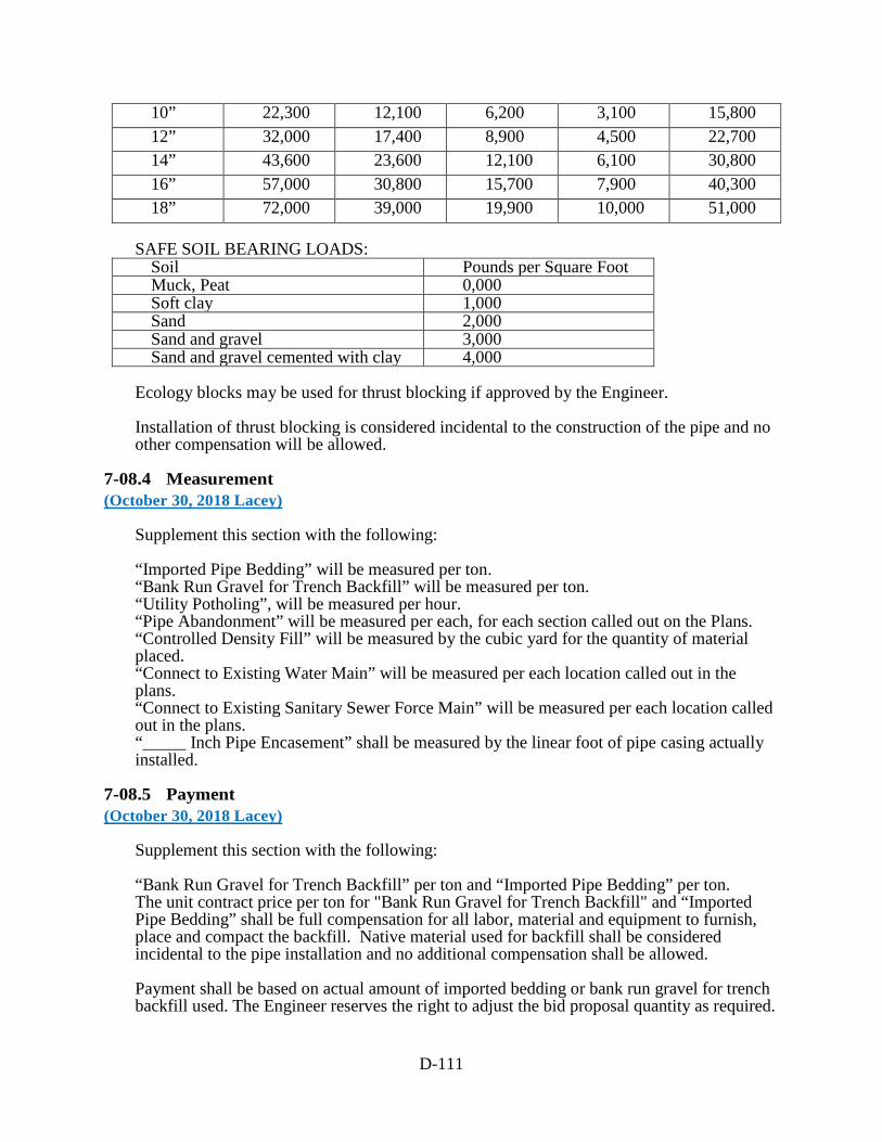
D-111
10” 22,300 12,100 6,200 3,100 15,800 12” 32,000 17,400 8,900 4,500 22,700 14” 43,600 23,600 12,100 6,100 30,800 16” 57,000 30,800 15,700 7,900 40,300 18” 72,000 39,000 19,900 10,000 51,000
SAFE SOIL BEARING LOADS: Soil Pounds per Square FootMuck, Peat 0,000Soft clay 1,000Sand 2,000Sand and gravel 3,000Sand and gravel cemented with clay 4,000
Ecology blocks may be used for thrust blocking if approved by the Engineer.
Installation of thrust blocking is considered incidental to the construction of the pipe and no other compensation will be allowed.
7-08.4 Measurement (October 30, 2018 Lacey)
Supplement this section with the following:
“Imported Pipe Bedding” will be measured per ton. “Bank Run Gravel for Trench Backfill” will be measured per ton. “Utility Potholing”, will be measured per hour. “Pipe Abandonment” will be measured per each, for each section called out on the Plans. “Controlled Density Fill” will be measured by the cubic yard for the quantity of material placed. “Connect to Existing Water Main” will be measured per each location called out in the plans. “Connect to Existing Sanitary Sewer Force Main” will be measured per each location called out in the plans. “_____ Inch Pipe Encasement” shall be measured by the linear foot of pipe casing actually installed.
7-08.5 Payment (October 30, 2018 Lacey)
Supplement this section with the following:
“Bank Run Gravel for Trench Backfill” per ton and “Imported Pipe Bedding” per ton. The unit contract price per ton for "Bank Run Gravel for Trench Backfill" and “Imported Pipe Bedding” shall be full compensation for all labor, material and equipment to furnish, place and compact the backfill. Native material used for backfill shall be considered incidental to the pipe installation and no additional compensation shall be allowed.
Payment shall be based on actual amount of imported bedding or bank run gravel for trench backfill used. The Engineer reserves the right to adjust the bid proposal quantity as required.

D-112
There will be no additional compensation made for the removal and wasting of trench excavation that is unsuitable for backfill.
If no bid item for “Bank Run Gravel for Trench Backfill” or “Imported Pipe Bedding” is included, any work described in these sections shall be included in the unit contract price per foot of pipe installed and no additional compensation shall be allowed.
“Utility Potholing”, per hour shall be full compensation for all labor, material and equipment necessary to excavate, backfill, and restore the utility location(s) required by the Engineer and determine its vertical and horizontal location. Utility potholing will only be paid for work approved by the Engineer in advance.
If no bid item for “Utility Potholing” is included, any work described in this section shall be incidental to the project.
“Pipe Abandonment”, per each. The unit contract price per each for “Pipe Abandonment” shall be full pay for providing all labor, tools, equipment and materials necessary to abandon the specified piping including the plug material.
If no bid item for “Pipe Abandonment” is included, any work described in this section shall be incidental to the project.
“Controlled Density Fill”, per cubic yard. If no bid item for “Controlled Density Fill” is included, any work described in this section shall be incidental to the project.
“Connect to Existing Water Main”, per each. The unit contract price for "Connect to Existing Water Main" shall be full pay for providing all labor, tools, equipment, and materials necessary to connect to the existing main. For purposes of payment, there will be no distinction made for the difficulty of connecting to the existing main or the quantity of connecting pipes or other materials needed. If no such item exists all costs shall be incidental to the project and no additional compensation shall be allowed.
“Connect to Existing Sanitary Sewer Force Main”, per each. The unit contract price for “Connect to Existing Force Main” shall be full pay for providing all labor, tools, equipment, and materials necessary to connect to the existing force main. For purposes of payment, there will be no distinction made for the difficulty of connecting to the existing main or the quantity of connecting pipes or other materials needed. If no such item exists all costs shall be incidental to the project and no additional compensation shall be allowed.
The unit contract price per linear foot of “______ Inch Pipe Encasement” shall be full compensation for all labor, material, tools and equipment to furnish, place, assemble, and install pipe casement, complete in place, including but not limited to pipe, all fittings including casing spacers, end seals and other fittings not shown on the Plans, joint materials, special requirements, commercial concrete or controlled density fill, and dewatering.
D-113
7-09 WATER MAINS
7-09.1 Description (January 3, 2017 Lacey)
Supplement this section with the following: Various transition couplings, flanged coupling adapters, transition couplings with follower flanges and gaskets, and other miscellaneous couplings and fittings may be required for performance under this project. It shall be the Contractor's responsibility to determine what specific couplings, adapters, and fittings that will be used to make connections shown on the plans. The Engineer has shown specific existing material types, and nominal sizes using the best information available. The Engineer has not determined the specific dimensions of existing materials. The Contractor shall submit a sketch showing configuration and materials of the proposed connection for review and approval. Where vertical bends or pipe ends are required, the pipe and fittings shall be restrained on each side of the bend for a distance as recommended by the manufacturer.
7-09.2 Materials (April 2, 2018 Lacey)
Supplement this section with the following: All pipe for water mains shall have flexible gasket joints and shall comply with one of the following two types unless otherwise specified on the plans: Ductile iron pipe conforming to AWWA C 151 Standard Thickness Class 52 and have a cement mortar lining conforming to AWWA C 104. All pipes shall be joined using non-restrained joints that shall be rubber gaskets, push on type or mechanical joint, conforming to AWWA C 111. PVC C900 pipe conforming to the latest revision of the following specifications, blue or white PVC Compound ASTM D1784 Class 12454B, Gasket ASTM F477, Manufacturing ASTM D2241. Pipe shall be certified NSF and meet requirements of Dimension Ratio 14. All pipe, 12 inches or larger in diameter shall be ductile iron pipe unless PVC is approved by the Engineer. Where restrained joint pipe is specifically identified on the plans, Ductile iron pipe, use restrained joint pipe with “Field Lok” type gaskets rated to 350 p.s.i and tested in accordance with ANSI/AWWA C111/A21.11, TR Flex as furnished by U.S. Pipe , Piranha as furnished by Romac, or Gripper Gasket LLC. PVC pipe 10 inches or less in diameter, use PVC C900/RJ Restrained Joint Pipe Certa-Lok by CertainTeed Corporation, Eagle Loc 900 by JM Eagle or Diamond Lok-21 by Diamond Plastics. The plastic pipe shall conform to the latest revision of the following specifications, PVC Compound ASTM D1784 Class 12454, Gasket ASTM F477, Manufacturing ASTM D2241. Pipe shall be certified NSF and meet requirements of Dimension Ratio 14.

D-114
PVC pipe larger than 10 inches in diameter, the pipe shall be restrained using bell joint restraint devices that have a working pressure of at least 200 psi with a minimum safety factor of 2:1 and shall be EBAA Iron, Inc., MEGALUG series 2800, Uni-Flange Series 1390, Romac Industries, Inc., U.S. Gripper, or approved equal. PE Pipe: All 2 inch and smaller diameter pipe shall be NSF Approved, PE3408 blue polyethylene pipe manufactured from virgin materials. Pipe shall meet the following specifications: • ANSI/AWWA C901 • ASTM D1248, ASTM D 3350, ASTM D 2239, ASTM D 3035 and ASTM D 2737, • Pressure Class 200, SIDR - 7(Standard Inside Dimension Ration-Pressure Rated), • Cell classification 345464C, Pipe shall be manufactured by Interstate Plastics, Philips Driscopipe, Eagle Pacific, Superlon Plastics, U.S. Poly or approved equal. All fittings for ductile iron pipe or PVC pipe shall be ductile iron compact fittings conforming to AWWA C 153 or conforming to AWWA C 110 and C 111. All shall be cement mortar lined conforming to AWWA C 104. Plain end fittings shall be ductile iron if mechanical joint retainer glands are installed on the plain ends. All fittings shall be flanged or mechanical joint. Fittings with restrained joints shall be mechanical joint fittings with a mechanical joint restraint device. The mechanical joint restraint device shall have a working pressure of at least 250 psi with a minimum safety factor of 2:1 and shall be EBAA Iron, Inc., MEGALUG, Ford Uni-Flange Series 1400, Romac Industries, Inc., U.S. Gripper, or approved equal. All pipe shall be new and in good condition with no visible signs of UV damage, fading or other defects.
7-09.3(19)B Maintaining Service (December 19, 2019 Lacey)
Supplement this section with the following: Where existing water services must be interrupted, the Contractor shall notify the Engineer as to the date, time and duration of the interruption, a minimum of 72 hours (3 working days) prior to the interruption. The Contractor shall field verify pipe diameter and fittings prior to requesting a service interruption. The City will notify customers involved or affected by the water service interruption. The Contractor shall make every effort to schedule water main construction with a minimum interruption of water service. Water service can not be interrupted before 8:00 am without prior approval from the Engineer in writing.
7-09.3(24) Disinfection of Water Mains (April 2, 2018 Lacey)
Modify this section with the following: The Contractor shall provide extra safeguards to prevent contamination, rocks, sand or foreign matter from accumulating in the pipe.

D-115
Unless otherwise approved by the Engineer, the method for disinfecting water mains shall be by dry Calcium Hypochlorite conforming to ANSI/ AWWA B300 and NSF/ANSI 61 as defined in Section 7-09.3(24)D of the WSDOT Standard Specifications and AWWA C651-14 Sec. 4.1.3 and Sec. 4.3. If adhesives are used to secure chlorine tablets to the pipe interior, they must meet the requirements of NSF/ANSI 61 and AWWA C651-14 Sec. 4.3.3. Pipe and fittings used in connections to existing mains shall be less than one pipe length (generally less than 20 ft), and spray disinfected, swabbed or immersed for disinfection as per AWWA C651-14 Sec. 4.10 and 4.11 (1% chlorine solution). Bacteriological testing shall be done by the City per AWWA C651-14 Sec. 5.1 Option A or B. Option B may not be able to be used if the pressure in the line is too low to allow the sample tap to run continuously for 15 minutes without opening the system valve. Bacteriological testing must be scheduled with the Engineer at least 3 days in advance and can not be done on Fridays. Results are typically provided within four (4) working days but may take up to (7) working days. If the samples fail to produce acceptable results, the main shall be re-chlorinated by the continuous-feed or slug method until satisfactory results are obtained per AWWA C651-14. The Contractor shall flush the new main. Flushing mains shall require the assistance of City utility personnel and shall be coordinated with the Engineer 3 working days in advance.
7-09.3(24)A Flushing (December 31, 2014 Lacey)
Modify this section by deleting the first sentence of the fourth paragraph and replacing it with the following: The Contractor shall be responsible for disposal of treated water flushed from mains and shall neutralize the wastewater for protection of aquatic life in the receiving water and their associated surface and ground water tributaries, before disposal into any natural drainage channel, i.e., receiving water, waters of the State, including wetlands.
7-09.5 Payment (October 30, 2018 Lacey)
Supplement this section with the following: The pay item in quotes is revised to read, “_____ Inch Water Main.” The unit contract price for “_____ Inch Water Main” per linear foot shall be full pay for furnishing all labor, materials, tools and equipment, necessary to install the water main, complete in-place, including but not limited to pipe, couplings, adaptors, crosses, tees, bends, reducers, caps, plugs, restrained joint fittings, bend markers, and other fittings not specifically identified on the plans. Further, all excavation, bedding, backfilling with native material, compacting, temporary patching, formed thrust blocking, testing, flushing, and disinfecting shall also be included in the unit contract price. Items not specifically identified on the plans but necessary to properly install the water main shall be considered incidental to the water main and no other compensation shall be allowed.
7-12.3(3) Raise Valve Box to Grade (December 31, 2014 Lacey)

D-116
Add the following new section: Where shown on the plans or where directed by the Engineer, existing valve boxes shall be raised to the grade as staked or otherwise designated by the Engineer. The Contractor shall supply and install new valve boxes and covers as part of raising valve boxes to grade. The finished installation shall conform to the detail shown in plans. All new and existing valve boxes located in any unpaved area shall have a concrete pad poured or placed entirely around each valve box. The pad shall be a minimum of 36 inches by 36 inches for each valve box. The concrete shall be commercial concrete or better with a minimum thickness of 8 inches. Maximum distance allowed from edge of iron ring or frame of appurtenance to outside edge of pavement restoration is 18 inches. Patches larger than this or clean misses (e.g. where the Contractor excavates in the new pavement mat and does not find the iron appurtenance to raise) shall result in a credit from the Contractor to the City of $1000 for each occurrence. Further, the Contractor shall repair the pavement patch as directed by the Engineer.
7-12.5 Payment (April 2, 2018 Lacey)
Supplement this section with the following: “Raise Valve Box to Grade,” per each. "_____ Inch Gate Valve," per each. The payment for the various items specified above shall be full pay for furnishing all labor, materials, tools, and equipment necessary to install the unit complete in place on the water main, including trenching, concrete pads and concrete or asphalt restoration of adjacent areas, disinfecting, testing, blocking of valve, valve box and marker post. 7-14 HYDRANTS
7-14.2 Materials (January 3, 2017 Lacey)
Modify this section with the following: Fire hydrants shall be Waterous Pacer, Mueller Centurion, M & H Reliant Style 929, Kennedy K-81, or EJIW 5CD250 conforming to AWWA C 502. The valve opening shall be 5 1/4-inch diameter. Hydrants shall be mechanical joint, 4-1/2 feet standard bury with two 2-1/2 inch outlets and one pumper port, and shall have a 1.25-inch pentagonal operating nut (counter clockwise opening). All hydrants shall be outfitted with a 4-1/2" NST by 5" Storz adapter with cap. Some locations may require other than the 4-1/2 feet standard bury. Contractor shall be responsible for determining actual required bury and provide proper standpipe height. Blow-off Hydrants shall be Eclipse MainGuard Model No. 78. Pipe and fittings for blow-off hydrant installation shall conform to the requirements of Section 7-15. The factory 2.5” cap shall be replaced with a plastic/nylon style cap with 2.5” NST thread.
7-14.3(1) Setting Hydrants (December 31, 2014 Lacey)

D-117
Supplement this section with the following: A 6 foot wide cleared area, centered along the pipe, shall extend from the edge of pavement to 3 foot past the new hydrant, not to exceed the right-of-way line. The clearing may include trimming of trees and shrubs to an overhead height of 10 feet as directed by the Engineer. Upon completion of fire hydrant installation, the cleared area shall be graded and restored as directed by the Engineer.
7-14.5 Payment (December 31, 2014 Lacey)
Supplement this section with the following: The unit contract price for all items in this section shall also include, but not be limited to, trench excavation and backfill, gravel backfill, fill and grading 3’ around hydrant and between hydrant and edge of roadway, painting, extensions, fittings, ductile iron spool, Storz adapter, Megalug restraining joints, and blue hydrant marker. “Blow-Off Hydrant Assembly”, per each. The unit contract price per each for “Blow-Off Hydrant Assembly” shall be full pay for furnishing all labor, materials, tools and equipment, necessary to the cap on the new water main, thread and install required valves, valves boxes, brass pipe, bends, couplings and other fittings not specifically called out on the plans.
7-15 SERVICE CONNECTIONS
7-15.2 Materials (April 2, 2018 Lacey GSP)
Supplement this section with the following: Service pipe from the main to the new meter shall be the appropriate size shown in the table below.
Meter Size Pipe Diameter 5/8” Single
1-1/2”
5/8” Double
1-1/2” 1” 1-1/2” 2” 2”
One and one-half and two inch diameter service lines shall be NSF Approved, PE3408 blue polyethylene pipe manufactured from virgin materials. Pipe shall meet the following specifications: • ANSI/AWWA C901 • ASTM D1248, ASTM D 3350, ASTM D 2239, ASTM D 3035 and ASTM D 2737, • Pressure Class 200, SIDR - 7(Standard Inside Dimension Ration-Pressure Rated), • Cell classification 345464C, Pipe shall be manufactured by Interstate Plastics, Philips Driscopipe, Eagle Pacific, Superlon Plastics, U.S. Poly or approved equal.

D-118
Service pipe from the new 5/8” meter to the old 5/8” meter location shall be minimum 1” diameter polyethylene plastic pipe minimum pressure Class 200. Service pipe greater than 100 ft. in length from new meter to old meter location shall be 1-1/2” diameter until it is connected to existing service line. The Contractor shall identify the diameter of the existing service line to remain in-place at the old meter location and provide the required fittings necessary for the transition. Service Saddle shall be ductile iron with double stainless steel straps or bands. All clamps or bands shall have rubber gaskets and I.P. threaded outlets (Ford FS202, Romac 202S or approved equal.) 1-1/2” Corporation Stop shall be all brass, “ball valve” type, male iron pipe thread inlet by pack joint outlet conforming to AWWA C800, Ford FB1101, Mueller E25029, AY McDonald 74704B-1.5” or approved equal. 2” Corporation Stop shall be Ford FB 11017G, Mueller H9969, AY McDonald 74704B-2” or approved equal. 1-1/2” Curb Stop shall be all brass, “ball valve” type, pack joint inlet by female iron pipe thread outlet conforming to AWWA C800, Ford B61, Mueller E25171, AY McDonald 76101-1.5” or approved equal. 2” Curb Stop shall be Ford FOB61-777, Mueller B20283, AY McDonald 76101-2” or approved equal. “U” Branch Piece for 5/8” double meter shall be all brass, 1” male iron pipe thread inlet by two ¾” male iron pipe outlets conforming to AWWA C800 (Ford U88-43-7.5, Mueller MH15364GFWD, AY McDonald 708UMM 1”x3/4”x7.5” or approved equal. Stainless steel inserts shall be used with all pack joint fittings. Further, all bushings, reducers, nipples, couplings, adaptors, and fittings required to make service connections shall be all brass conforming to AWWA C800 manufactured by Ford or approved equal. Meter setters shall be all copper, Ball valve style with locking wing and check valve. The Contractor shall remove and reinstall the existing meter in the new setter after testing of new water main and service line. The Contractor shall use care in removing and reinstalling the existing meter. All fittings and meters shall be kept clean and free of dirt or foreign material and sprayed with a light bleach / chlorine solution prior to installation. Services shall be flushed at the customer hose bib after final meter installation to clear the service line, remove air and to verify good flow. All costs for replacing a broken meter due to the Contractor’s neglect shall be borne by the Contractor.
Meter Size Meter Setter
5/8” Single Meter
Ford VH 72-15W or Mueller B2404-R2EF15 or AY McDonald AY-720-215WCD 5/8” Double
Meter Ford VH 72-15W (2 ea) or Mueller B2404-R2AG15 (2ea) or AY McDonald AY-720-215WCD (2ea)
1” Meter Ford VBH 74-15W or Mueller B2404-R2AG15 or AY McDonald AY-720-415WCDD
1-1/2” Meter Ford VBH 76-15HB or Mueller B2423-29900015-15 with high by-pass or AY McDonald AY-720R615WDFF

D-119
2” Meter Ford VBH 77-15HB or Mueller B2423-29900015-2 with high by-pass or AY McDonald AY-720R715WDFF
Meter boxes shall be placed in non-traffic or non-parking areas whenever possible. Meter boxes and lids shall be Christy Fibrelyte. Covers with reader doors in them will not be allowed. Meter boxes may be placed in traffic/parking areas if shown on the plans or as directed by the engineer. In these areas the meter boxes shall be Old Castle or Christy reinforced concrete with a steel H20 traffic rated cover marked water.
Meter Size Meter Box Meter Box
5/8” Single Meter
Christy Fibrelyte FL30T-12
Christy Fibrelyte FL30-D with “City of Lacey” in the lid
5/8” Double Meter
Christy Fibrelyte FL36T-12
Christy Fibrelyte FL36-D with “City of Lacey” in the lid
1” Meter Christy Fibrelyte FL36T-12
Christy Fibrelyte FL36-D with “City of Lacey” in the lid
1-1/2” Meter Christy Fibrelyte FL36T-18
Christy Fibrelyte FL36-D with “City of Lacey” in the lid
2” Meter Christy Synertech SYN2436T-18
Christy Synertech SYN2436T with “City of Lacey” in the lid
Imported service line bedding shall meet the requirements of Section 9-03.16. See Section 7-08 “Imported Pipe Bedding” for measurement and payment of service line bedding.
7-15.3 Construction Requirements (December 19, 2019 Lacey)
Supplement this section with the following: The Contractor shall locate and verify the size and type of existing services. The approximate locations of the existing services are shown on the Plans. Existing services may be located on private property, close to buildings, in backyards, or other complex construction locations. The Contractor shall notify private property owners 24 hours prior to any scheduled water outage. In addition, the Contractor shall knock on the door of the house affected one hour before the outage and notify the homeowner of the outage. Disruption of existing services shall be minimized. Service line from the new water main to the new meter setter, including the new meter setter, shall be bedded with imported service line bedding. The service line from the new meter setter to the connection to the existing service line shall be bedded with suitable native material as directed by the Engineer. Unless noted otherwise in the plans, all existing meter setters along with associated box, plumbing and hardware must be removed and replaced. Existing meters shall be re-used unless noted otherwise.

D-120
The Contractor shall take special care with the work on private property. The Contractor shall verify with the Engineer and/or Property Owner final service line route that will minimize damage to landscaping or improvements, and restore all damaged items to a condition equal to or better than the original condition. For service lines crossing under sidewalks, driveways, or landscaped areas, the Contractor shall layout new service line routes prior to excavation for approval by the Engineer. Service line routes should minimize removal of asphalt, concrete, and mature landscaping.
7-15.3(2) Connection To New Water Main (January 3, 2017 Lacey)
Add the following new section: Service lines between the new water main and the existing service line past the existing meter setter shall be installed prior to testing and disinfecting the new water main. Disinfect fittings and pipe prior to installation. Installation/replacement of a service to a new water main shall include the following: • install new service line to new meter setter and box, • install new service line from new meter setter to existing meter service, • verify each individual existing water service is disconnected, • remove old service to include; meter, meter box, setter, and any associated
appurtenances, • reinstall existing meter in new meter setter, • connect new service line to existing service line on the property side of the old service
(no jumpers will be allowed at existing setters). • coordinate with the customer to flush the service line at the customer’s outside faucet and
verify all faucets are functioning If after abandoning the old water main(s) it is determined that a customer is without water and a service was not shown on the plans at that particular location, the Contractor shall within 24 hours install a new service connection as directed by the Engineer.
7-15.3(3) Connection To Existing Water Mains (January 3, 2017 Lacey)
Add the following new section: Disinfect fittings and pipe prior to installation. Connection of a service to an existing water main shall include the following: • locate, excavate, and connect to the existing water main, • install new service (with or without meters as identified on the plans), • verify each individual existing water service is disconnected (unless meter credit is
noted), • remove old service to include; meter, meter box, setter, and any associated appurtenances
(unless meter credit is noted), • install a service line from the new service to the existing service line on the property side
of the old service (unless meter credit is noted). If after abandoning the old water main(s) it is determined that a customer is without water and a service was not shown on the plans at that particular location, the Contractor shall within 24 hours install a new service connection as directed by the Engineer.
D-121
7-15.3(5) Repair of Existing Water Service (January 3, 2017 Lacey)
Add the following new section:
If while pushing or excavating, an existing service line is broke. The Contractor shall follow the course of action as stated below: • Immediately call or notify the Engineer• Crimp service line if possible,• If needed, assist the Engineer or City of Lacey Water repair crew to throttle down the
water main,• Disinfect all fittings and pipe prior to installation. Excavate and repair broken service line
while under the direct supervision of the Engineer or wait for assistance from the City ofLacey Water repair crew,
• Flush repaired service line at setter with the assistance of the Engineer until water flowbecomes clean, inspect and flush setter and meter, reconnect old service line to metersetter (if applicable) and resume service to residence. Flush hose bib at residence orbuilding until air is removed and water runs clear.
7-15.3(6) Irrigation and Electrical Systems Testing and Repair (December 31, 2014 Lacey)
Add the following new section:
The Contractor shall operationally test existing irrigation and landscape electrical systems prior to construction at individual residences. If it is found through the baseline tests that an existing system does not operate correctly, the Contractor shall demonstrate the discrepancy to the Engineer and the problem(s) will be documented. The Contractor shall take precaution to avoid cutting or breaking of lines and services during service line installation. If a line is cut or broke, the Contractor shall immediately repair and test the system prior to continuing on with other service line installations.
Upon completion of the service line installation, the Contractor shall once again test the existing systems and compare to the baseline tests conducted prior to work within the yard. Any discrepancies between the baseline test and the final tests shall be repaired prior to continuing on with other service line installations.
7-15.3(8) Adjust Water Meter (April 30, 2015 Lacey)
Add the following new section:
The Contractor shall adjust the setter, water meter, and meter box to finished grade as shown on the plans or where directed by the Engineer.
7-15.5 Payment (October 16, 2016 Lacey)
Supplement this section with the following:
“___Inch Single Meter Service Connected to Existing Water Main”, per each. “___Inch Double Meter Service Connected to Existing Water Main”, per each. “___Inch Single Meter Service Connected to New Water Main”, per each.
D-122
“___Inch Double Meter Service Connected to New Water Main”, per each.
The unit contract price for the above bid items shall be full compensation for all labor, material, and equipment to furnish and install the meter service(s) complete including, but not be limited to, service saddle, tapping the pipe, corporation stops, service lines, meter, meter setter or tandem setter, pressure reducing valve(s), meter box, and all miscellaneous couplings, fittings, and adapters to install the service lines and connect to the existing service. Furthermore, pushing, boring, or directional drilling of new service line including encasement, repair of broken utility and service lines, and lawn and landscape restoration per service install is included.
Progress payment of 50% shall be allowed once service line(s) is installed up to existing meter setter(s) and water main and service lines are flushed and tested. Complete and final payment shall be allowed once residence(s) has full use of new system and repair of lawn and landscaping is completed.
For purposes of payment, there will be no distinction made for the difficulty of disconnecting the old meter and reconnecting to the new meter or the length of service line required for each new meter service.
“Adjust Water Meter”, per each. The payment for the items specified above shall be full pay for furnishing all labor, materials, tools, and equipment, and disposing of removed materials necessary or incidental to furnishing and installing the unit complete in place.
“___ Inch Single Service Pressure Reducing Valve with Tandem Setter”, per each. “___ Inch Double Service Pressure Reducing Valves with Tandem Setters”, per each.
8-01 EROSION CONTROL AND WATER POLLUTION CONTROL
8-01.3 Construction Requirements
8-01.3(1) General (January 5, 2015 WSDOT)
The first through eighth paragraphs of Section 8-01.3(1) are deleted and replaced with the following:
The Contractor shall install a high visibility fence along the site preservation lines shown in the Plans or as instructed by the Engineer.
Throughout the life of the project, the Contractor shall preserve and protect the delineated area, acting immediately to repair or restore any fencing damaged or removed.
Controlling pollution, erosion, runoff, and related damage requires the Contractor to perform temporary Work items including but not limited to:
1. Providing ditches, berms, culverts, and other measures to control surface water.
2. Building dams, settling basins, energy dissipaters, and other measures, to controldownstream flows.

D-123
3. Controlling underground water found during construction. 4. Covering or otherwise protecting slopes until permanent erosion-control measures are working. To the degree possible, the Contractor shall coordinate this temporary Work with permanent drainage and erosion control Work the Contract requires. All sediment control devices including, but not limited to, sediment ponds, perimeter silt fencing, or other sediment trapping BMPs shall be installed prior to any ground disturbing activity. Clearing, grubbing, excavation, borrow, or fill within the Right of Way shall never expose more erodible earth than as listed below:
Western Washington (West of the Cascade Mountain Crest)
Eastern Washington (East of the Cascade Mountain Crest)
May 1 through September 30
17 Acres April 1 through
October 31 17 Acres
October 1 through April 30
5 Acres
November 1 through March 31
5 Acres
8-01.3(1)A Submittals (August 3, 2015 WSDOT)
Section 8-01.3(1)A is revised to read: A Temporary Erosion and Sediment Control (TESC) Plan consists of a narrative section and plan sheets that meets Ecology’s Stormwater Pollution Prevention Plan (SWPPP) requirement in the CSWGP. When the Contracting Agency has developed a TESC Plan for a Contract the narrative is included in the appendix to the Special Provisions and the TESC plan sheets are included in the Contract Plans. The Contracting Agency TESC plan will not include off-site areas used to directly support construction activity. The Contractor shall either adopt the TESC Plan in the Contract or develop a new TESC Plan. If the Contractor adopts the Contracting Agency TESC Plan the Contractor shall modify the TESC Plan to meet the Contractor’s schedule, method of construction, and to include off-site areas that will be used to directly support construction activity such as equipment staging yards, material storage areas, or borrow areas. Contractor TESC Plans shall include all high visibility fence delineation shown on the Contracting Agency Contract Plans. All TESC Plans shall meet the requirements of the current edition of the WSDOT Temporary Erosion and Sediment Control Manual M 3109 and be adapted as needed throughout construction based on site inspections and discharge samples to maintain compliance with the CSWGP. The Contractor shall develop a schedule for implementation of the TESC work and incorporate it into the Contractor’s progress schedule. The Contractor shall submit their TESC Plan (either the adopted plan or new plan) and implementation schedule as Type 2 Working Drawings. At the request of the Engineer updated TESC Plans shall be submitted as Type 1 Working Drawings.
D-124
8-01.3(1)B Erosion and Sediment Control (ESC) Lead (January 5, 2015 WSDOT)
Supplement this section with the following: The ESC Lead shall implement the TESC Plan. Implementation shall include, but is not limited to: 1. Installing and maintaining all temporary erosion and sediment control Best Management Practices (BMPs) included in the TESC Plan to assure continued performance of their intended function. Damaged or inadequate TESC BMP’s shall be corrected immediately. 2. Updating the TESC Plan to reflect current field conditions. 3. Discharge sampling and submitting Discharge Monitoring Reports (DMRs) to Ecology in accordance with the CSWGP. 4. Develop and maintain the Site Log Book as defined in the CSWGP. As a part of the Site Log Book, the Contractor shall develop and maintain a BMP tracking table to show that identified TESC compliance issues are fully resolved within 10 calendar days. The table shall include the date an issue was identified, a description of how it was resolved, and the date the issue was fully resolved. The ESC Lead shall also inspect all areas disturbed by construction activities, all on-site erosion and sediment control BMP’s, and all stormwater discharge points at least once every calendar week and within 24-hours of runoff events in which stormwater discharges from the site. Inspections of temporarily stabilized, inactive sites may be reduced to once every calendar month. The Erosion and Sediment Control Inspection Form (WSDOT Form 220-030) shall be completed for each inspection and a copy shall be submitted to the Engineer no later than the end of the next working day following the inspection.
8-01.3(2) Seeding, Fertilizing and Mulching (July 17, 2012 Lacey GSP)
Supplement this section with the following: The Contractor shall provide water or irrigation to all seeded areas as often as conditions dictate depending on weather and soil conditions. Water will be provided as described in Section 2-07.
8-01.3(2)A Preparation For Application (October 16, 2009 Lacey GSP)
Supplement this section with the following: All landscaped areas in the Plans shall be cultivated to the requirements in this section.
8-01.3(2)B Seeding And Fertilizing (December 31, 2014 Lacey GSP)
Supplement this section with the following:

D-125
Seed and fertilizer shall only be sown by Method 1 as approved by the Engineer. Seed shall be broadcast with approved hydraulic seeding equipment, in combination with wood cellulose fiber mulch, soil stabilizer and fertilizer distributed uniformly over designated areas. Half of seed shall be sown with sower moving in one direction, the other half with sower moving at right angles to first sowing. Hydroseeding operator shall remove all seed mulch in its entirety from adjoining paving, structures and plants.
8-01.3(2)D Mulching (October 16, 2009 Lacey GSP)
Supplement this section with the following: Wood cellulose fiber mulch shall be applied at a rate of 2000 pounds per acre. Straw Mulch will not be permitted.
8-01.3(2)F Dates For Application Of Final Seed, Fertilizer, And Mulch (December 31, 2014 Lacey GSP)
Delete the second paragraph of this section and replace with the following: Hydroseeding shall occur on all areas shown in the plans. Hydroseeding shall occur between August 15 and September 30 or between March 15 and May 15. In areas receiving automatic irrigation, hydroseeding may occur between May 15 and August 15. Actual planting shall be performed only when weather and soil conditions are suitable and in accordance with locally accepted practice and/or approved by the Engineer. Hydroseeding shall not be attempted when wind velocities would prevent uniform application or when winds would drift the material outside the areas to be seeded. Supplement this section with the following: The Contractor shall provide proposed mix proportions, submittals, seed certification, and certification of compliance of all materials used a minimum of 5 working days before seeding is to begin, for the Engineer’s written approval.
8-01.3(9)A2 Silt Fence (October 16, 2014 Lacey GSP)
Supplement this section with the following: If the Engineer determines that site conditions dictate additional silt fence throughout the duration of the project, the Contractor shall immediately install additional silt fence as directed by the Engineer.
8-01.3(9)D Inlet Protection (July 17, 2012 Lacey GSP)
Delete the first paragraph and replace with the following: All catch basins and inlets within the project limits, downstream or affected by construction activities shall have inlet protection and as required by the Engineer. Inlet protection devices shall be installed prior to beginning clearing, grubbing, or earthwork activities.

D-126
8-01.3(15) Maintenance (January 5, 2015 WSDOT)
The fifth paragraph of Section 8-01.3(15) is deleted.
8-01.3(16) Removal (January 5, 2015 WSDOT)
The Contractor shall remove all temporary BMP’s and all associated hardware from the project limits prior to Physical Completion unless otherwise approved by the Engineer. At the request of the Contractor and at the sole discretion of the Engineer the CSWGP may be transferred back to the Contracting Agency. Approval of the Transfer of Coverage request will require the following: 1. All other Work required for Contract Completion has been completed. 2. All Work required for compliance with the CSWGP has been completed to the maximum extent possible. This includes removal of BMPs that are no longer needed and the site has undergone all Stabilization identified for meeting the requirements of Final Stabilization in the CSWGP. 3. An Equitable Adjustment change order for the cost of Work that has not been completed by the Contractor. 4. Submittal of the Washington State Department of Ecology Transfer of Coverage form (Ecology form ECY 020-87a) to the Engineer. If the Engineer approves the Transfer of Coverage back to the Contracting Agency the requirement in Section 1-07.5(3) for the Contractor’s submittal of the Notice of Termination form to Ecology will not apply.
8-01.4 Measurement (April 30, 2015 Lacey GSP)
Supplement this section with the following: All items required for erosion control shall be included in the lump sum bid item “Erosion/Water Pollution Control” unless a specific bid item is included in the proposal. Modify this section with the following: No specific unit of measure shall apply to the lump sum item “ESC Lead”
8-01.5 Payment (October 16, 2016 Lacey GSP)
Modify this section with the following: “Silt Fence”, per linear foot. “High Visibility Silt Fence”, per linear foot The unit contract price per linear foot shall be full pay for all equipment, labor and materials to install, maintain, remove and dispose of the silt fence as shown in the Plans and as directed by the Engineer.

D-127
The lump sum contract price for “ESC Lead” shall be full compensation for all labor, material, tools, and equipment necessary to meet the requirements of Section 8-01.3(1)B to include conduct site inspections, stormwater sampling, report preparation, report submittal, lab work, and personnel certification. The unit contract price per acre for "Seeding, Fertilizing, and Mulching", shall be full compensation for all labor, material, tools and equipment necessary to place, protect, irrigate and maintain all items as specified. The Contractor shall receive payment of 60 percent of the unit contract price, per acre, upon the completion of the initial hydroseeding. Payment shall be increased to 100 percent of the unit contract price, per acre, upon the point where the first mowing is required, as determined by the Engineer. All partial payments shall be limited to the actual area of weed free healthy vigorous growth. Partial payments shall not constitute acceptance of the area, nor shall the ownership or title transfer to the Contracting Agency. Areas found not acceptable at any stage shall be rejected and replaced at the Contractor’s expense. Previous partial payments made for areas rejected will be deducted from future payments due the Contractor. Delete “Erosion/Water Pollution Control”, by force account and add the following bid item: “Erosion/Water Pollution Control”, lump sum. The lump sum contract price for “Erosion/Water Pollution Control” shall be full compensation for all labor, material, and equipment necessary to implement, install, maintain and remove all erosion and water pollution control items including removal and disposal of sediment, stabilization and rehabilitation of soil disturbed by these activities, and any additional Work deemed necessary by the Engineer to control erosion and water pollution and all Work required for compliance with the Construction Stormwater General Permit (CSWGP) including annual permit fees. The requirements for the ESC Lead shall also be included in this lump sum bid item if no bid item is included in the proposal. The Contractor shall bear full responsibility for erosion/water pollution control in all sources of material, disposal sites, and haul roads.
8-02.2 Materials (October 29, 2010 Lacey)
Supplement this section with the following: The pond liner shall be organic muck material or sandy loam. The material is intended to create an impermeable liner in the bottom of the storm pond. The Contractor shall submit a sample of the pond liner to the Engineer for approval prior to placement. The pond liner material shall have the following characteristics: Silt content Maximum 30% Clay content Maximum 15% Soil organic content Minimum 5% by weight (ASTM D2974) The water percolation/infiltration rate shall be a maximum of 2.4 inches per hour to provide adequate water quality treatment.

D-128
The Contractor shall submit soil analysis from a soils testing laboratory to the Engineer. Indicate source(s) and obtain the Engineer’s approval before hauling to the site or placement.
Materials shall meet the requirements of the following publication:
American Standard for Nursery Stock, ANSI Z60.1-2004, American Nursery and Landscape Association.
Plant varieties shall be as specified in the plant material list and be true to botanical name as listed in the latest edition of “Standardized Plant Names” as adopted by American Joint Committee of Horticulture Nomenclature.
Plants shall be nursery-grown unless otherwise indicated. Plants are required to be from stock acclimated to project site environmental conditions, having been consistently cultivated and grown under site conditions. No cold storage plants will be permitted. Grafted trees shall be done within 3 inches of ground level. Plant material conditions shall meet the following requirements:
Be fresh, well foliated, in prime condition when in leaf and exhibiting normal habit of growth. Have all leaders and buds intact, free of disease, injury, insects, insect eggs, larvae and indications of strawberry root weevil. Be free of seeds; weeds, weed roots and other such contaminants.
The Contractor shall notify the Engineer 3 days prior to delivery of any plants. The Engineer will approve all plants before unloading. Any plants that are rejected shall be removed from the project site immediately and replaced with acceptable plants.
Ball and burlapped (B&B) stock is required to have a natural ball sufficient to ensure survival and healthy growth.
Bare root (BR) material is required to have sufficient, intact root systems to ensure survival and healthy growth.
Container-grown plants are required to have sufficient growth to hold the earth intact when removed from containers, but shall not be root-bound.
Geotextile root control system shall be NDS Root Barrier Panel Model No. EP-2450 or Engineer approved equal.
8-02.3(4) Topsoil (October 16, 2016 Lacey)
Supplement this section with the following:
The Contractor shall thoroughly scarify the subgrade by tilling, disking or harrowing after the subgrade elevation has been established as indicated on the Plans.
Prior to placement of topsoil, the Engineer shall approve native or imported material. If the Contractor furnishes and places Topsoil Type A in the roadside planting areas without prior approval, it shall be done at the Contractor’s expense. Final grading shall include raking, floating, dragging, and rolling to remove all surface irregularities and to provide a firm,

D-129
smooth surface with positive drainage. Imported topsoil shall not be placed more than 3 days prior to permanent seeding. The Contractor may take samples of the topsoil to be removed for testing. If soil samples from areas to be removed are shown to meet the requirements, the Engineer may adjust the quantity to be removed as represented by the passing samples. All costs incurred by the Contractor to test topsoil shall be borne by the Contractor and no further compensation will be allowed. The Contractor shall submit a stockpile plan that identifies the stockpile location and stockpile limits for approval by the Engineer. The plan shall also be approved by the Owner prior to beginning stockpiling operations.
8-02.3(4)A Topsoil Type A (October 16, 2019 Lacey)
Supplement this section with the following: The Engineer will approve topsoil prior to procurement and placement. Topsoil Type A shall meet all requirements of Special Provision 9-14.1(1). Topsoil shall be placed at 12” depth in planter strips, and 18” depth in medians and tree wells, and a minimum of 42” inches below the top of curb in the roundabout island unless otherwise shown in the Plans. Within the central island of the roundabout, the Contractor shall excavate to the subgrade of the roadway and thoroughly scarify the subgrade by tilling, disking or harrowing. The intent is to utilize topsoil completely within the central island. Provide and install Topsoil Type A to the specified depth in all tree, shrub, groundcover, and other planting areas.
8-02.3(5) Planting Area Preparation (October 16, 2016 Lacey)
Section 8-02.3(5) is supplemented with the following: Planting area preparation will be required in all landscaped areas as shown on the Plans. Planting area preparation shall include removal of existing vegetation, construction debris, all visible rocks or other detrimental material from planter strips located within the project limits before adding soil amendments to the imported topsoil for the roadside planting areas, uniformly tilling the soil amendments into the top 8”-12” of soil, using a rototiller or similar machine, grading the blended soils, and then thoroughly watering down. Planting area preparation in the roadside includes preserving and protecting existing trees. Where noted on plan, Engineer shall identify and mark existing trees to be saved. Following marking, Contractor shall provide and place Engineer approved high visibility orange plastic fence around critical root zones of each marked tree or tree groupings. Do not begin construction activity on the roadsides until all plastic mesh fencing is in place, and approved by the Engineer. Identify existing trees that are to be removed, that were not removed during roadway construction, prior to starting planting. Obtain approval to remove existing trees from

D-130
Engineer. Contractor to provide, install and maintain tree protection throughout project duration. All planting area preparation shall be conducted under favorable weather conditions only. Soil shall not be worked when excessively dry or wet. Engineer reserves the right to stop any work taking place when conditions are considered detrimental to soil structure or plant growth. All planting areas shall be weed free and approved by the Engineer before starting rototilling (with soil amendments distributed over designated surface areas) and after rototilling has been completed. All beds shall then be approved by the Engineer for fine grading, before starting any planting operations. All planting surface areas shall be left with a firm, uniform surface, free of weeds and undulations or other irregularities. Remove all rocks, clods, and debris from all planting surfaces, unless otherwise specified on the plans or directed by the Engineer. Preliminary grading shall be done in such a manner as to anticipate the finished grades after placement of topsoil, soil amendments and bark mulch (if specified). Excess soil shall be removed or redistributed before application of soil mix, fertilizer, and mulch. Where soil is to be replaced by plants and mulch, allowance shall be made so that when finish grading has begun, there shall be no deficiency in the specified depth of mulched planting beds. The Contractor shall bear final responsibility for proper surface drainage of the site and the features thereon. Any discrepancy in the drawings or specifications, obstructions on the site, or prior work done by another party which the Contractor feels precludes establishing proper drainage, shall be brought immediately to the attention of the Engineer in writing for correction or relief of said responsibility.
8-02.3(7) Layout of Planting (January 3, 2017 Lacey)
Delete this section and replace with the following: All location layout and staking will be the responsibility of the Contractor. Tree and plant locations shown shall be considered approximate unless otherwise noted or shown with specific distance. Tree locations may be adjusted, with prior Engineer approval, so that the tree does not interfere with sightline requirements, street signs, irrigation, overhead utilities, or any other apparatuses such as utilities. Do not locate or plant any tree within 15 feet of a streetlight. Do not locate or plant any tree within 3 feet of a utility vault, 2.5 feet of back-of-sidewalks or back-of-curbs, and 15 feet of a fire hydrant. In mixed planting areas, trees shall be planted first, followed by the larger shrubs, low shrubs, and then groundcover material. The Contractor shall layout all trees and plants in the approximate location for approval by the Engineer. All coordination shall be done with the Engineer.
8-02.3(8) Planting (October 29, 2010 Lacey)
D-131
Supplement this section with the following: The Contractor shall make required field adjustments as directed by the Engineer without additional cost and to avoid obstructions. Plants not properly planted or temporarily heeled-in will be rejected and shall be removed from the site. Maintenance shall begin following the installation of each plant and shall continue until project acceptance. Work includes, but is not limited to, watering, weeding, cultivating, tightening, and repairing guys, removal of dead materials, resetting plants to proper grades or upright positions and other operations necessary to ensure proper growth and survival of all plant material. If it is discovered that Common horsetail (Equisetum Arvense) has been imported with plant material, the Contractor shall remove the tree or shrub in its entirety including the rootball and surrounding soil, and replace the tree or shrub in-kind. Before excavation, plants to be installed shall be placed as indicated on Planting Plan. The Engineer shall check locations of all plants in the field and shall indicate the exact position before actual planting operation proceeds. Set trees and shrubs in center of pits, plumb and straight. Plant at such a level that after settlement, the crown of the plant will be slightly above finish grade. Set plants in backfill mixture to such depth that the top of the plant ball will be slightly above finished grade. Backfill the remainder of the hole and soak thoroughly. Water the backfill until saturated to the full depth of the hole. A mound of earth shall be formed as directed around each tree and shrub so as to produce a shallow basin to retain water, the diameter to exceed the diameter of the root spread at planting. Plants shall be watered in place during and after backfilling. Prune plants only at time of planting and according to standard horticultural practice to preserve the natural character of the plant. All pruning shall be done under supervision of Engineer. Remove all dead wood, suckers, and broken or badly bruised branches, unless plants are deemed to be unacceptable and rejected by the Engineer. Use only clean, sharp tools. Immediately after planting operations are complete, all planting beds and plant pits shall be dressed off so as to achieve a neat and presentable appearance. Planting operations shall be identical for all plants to be planted. Refer to Plans, specifications and directions from Engineer. If applicable, Contractor shall plant trees, shrubs, and groundcover material in non-irrigated areas between October 1, and January 31. Plant bare root and live cutting material during winter dormancy (November 30 and February 1) unless otherwise directed by the Engineer. Install live cuttings the same day as harvest or cutting from parent material. Notify the Engineer a minimum of 48-hours before beginning any roadside planting-related work.

D-132
8-02.3(10) Fertilizers (October 16, 2009 Lacey)
Supplement this section with the following: Fertilizer shall be applied over the surface of plant basin at indicated rates. Install fertilizer tablets as specified. Fertilizer shall meet all requirements of Special Provision 9-14.3. All trees shall have an application of beneficial mycorrhizal fungi applied at time of planting in accordance with the manufacturer’s recommendations.
8-02.3(11) Bark or Wood Chip Mulch (October 16, 2009 Lacey)
Supplement this section with the following: Bark mulch shall be a pathogen-free medium-grind Hemlock or Douglas Fir bark mulch. The Contractor shall submit a sample to the Engineer for approval prior to use.
8-02.4 Measurement (April 4, 2016 Lacey)
Supplement this section with the following: Topsoil, compost and mulch will be measured by the cubic yard. Tree stakes, fertilizer, headers, planting area preparation, planting area weed control, and tree protection will be incidental to the “unit costs” of plantings as specified. The measurements for each plant will be made for the size and type of plant shown in the plans.
8-02.5 Payment (October 16, 2016 Lacey)
This section with the following: Payment will be per each for all plant bid items included in the bid proposal under the Botanical and Common Name for each plant. The unit contract price per each for each plant shall be for full compensation for all labor, material and equipment necessary to install and maintain all items as specified complete. Price shall also include but not be limited to preparation, delivery, planting, protecting, pruning, rebar ties, tree stakes, guying, wrapping, rubber tree tie, fertilizer, pre-emergent and post-emergent herbicides, and geotextile root control system as shown in the Plans. Excavation for the roadside planting areas will be considered incidental to the bid item for topsoil placement. The following bid items shall be full pay for furnishing all labor, materials, tools and equipment, necessary to scarify the subgrade, install, rake, remove debris such as rocks and organic material and shape the material as shown in the plans: “Topsoil Type A”, per cubic yard,
D-133
“Fine Compost”, per cubic yard, “Medium Compost”, per cubic yard, “Coarse Compost”, per cubic yard, “Soil Amendment”, per cubic yard, “Bark or Wood Chip Mulch” per cubic yard.
8-03 IRRIGATION SYSTEMS
8-03.3 Construction Requirements (October 29, 2010 Lacey GSP)
Delete the first paragraph of this section and replace with the following:
The Contractor shall design and construct the irrigation system, including water service taps, for all areas required to be irrigated as shown on the Plans. Contractor shall have the proposed irrigation design independently reviewed by a competent irrigation design specialist as approved by the Engineer (i.e. Landscape Architect, Certified Landscape Irrigation Auditor, etc.). All deficiencies identified by the independent reviewer shall be corrected prior to submitting the design to the Engineer for final approval. The independent review shall be documented by the Contractor, indicating the name of the reviewer and date the review occurred, and submitted to the Engineer as part of the final review. All costs for the independent design review will be the responsibility of the Contractor and no additional compensation shall be allowed. The design shall be submitted a minimum of 30 days before starting irrigation installation work with Engineer approval.
The design shall be submitted to the Engineer as either an electronically produced (CADD) drawing(s) or on mylar plan(s). Contractor may request the Engineer provide an electronic drawing file (AutoCAD) or plastic mylar site plan(s), as base files for the contractor-provided irrigation design.
During construction, the Contractor shall prepare and maintain a Record Drawing as-constructed (prints) of the irrigation system(s) on-site at all times. The Contractor shall update the prints weekly and make them available to the Engineer, upon request for review and inspection. Updates shall include all work completed to date including changes in design. Upon completion of the irrigation system, the prints shall be given to the Engineer for review. The Contractor will be required to complete all Record Drawing changes and corrections, then finalize the prints, and deliver to the Engineer upon completion.
The Contractor shall include the following requirements for the irrigation system design:
1. Use point-of-connection and sleeves as shown on the Plans.2. Provide 100% water coverage to all areas identified in the plans.3. Irrigate seeded areas, shrub areas, and street trees (with grates) using separate remote
control valve zones.4. Field verify the points-of-connection for the roadsides, and the locations of water and
electrical service lines prior to starting irrigation construction.5. Verify available water service line hydro-static water pressure and available flow (system
operation: 10 p.m.-6 a.m.) prior to starting irrigation construction, and reportfindings/concerns to the Engineer immediately upon discovery.
6. Include remote control valve wire, automatic controllers, and electrical serviceconnections in the irrigation design.
7. Provide head-to-head coverage and design using matched precipitation rate heads.

D-134
8. Provide a low-flow, drip irrigation system that will deposit water uniformly throughout the planted beds.
9. All tree wells shall be isolated into separate zones 10. Show all mainline and lateral pipe sizes, remote control and isolation valves, sprinkler
heads, drip zones, and other equipment. 11. At each valve location show Valve I.D. number. 12. Drainage out of the lowest heads on sprinkler zones shall not occur when the system
shuts off. 13. Individual irrigation zones shall have matching manufacturer make and model sprinkler
heads or dripline emitters with matched precipitation rates and performance characteristics.
14. Never exceed manufacturer’s recommendation for maximum velocities and flow rates. 15. Locate irrigation equipment for convenient operation and maintenance. All underground
equipment, excluding pipe, shall be installed in irrigation valve boxes and vaults. 16. Install thrust blocking on mainlines three inches in diameter or greater. 17. Take care to minimize the potential for vandalism, especially with the temporary on-
grade irrigation components, during and after construction to the maximum extent possible.
8-03.3(1) Layout of Irrigation System (October 29, 2010 Lacey)
Delete the first sentence of this section and replace with the following: The Contractor shall stake the irrigation system according to the design and receive approval of staked locations from the Engineer prior to construction.
8-03.3(3) Piping (January 3, 2017 Lacey)
Supplement this section with the following: All pipes shall have a 12” minimum separation from sidewalks, curbs, walls, and fences. Parallel pipes shall have 3” minimum separation. Pipe depths shall be as follows:
1. PVC pipe on pressure side of irrigation control valve, control wires and quick-coupling valves (pressure mainlines): 18” minimum cover.
2. Pipe on non-pressure side of irrigation control valve (lateral lines): 12” minimum cover. 3. Sleeving: 24” minimum cover. 4. Drip tubing shall be a minimum of 6” below finished grade. Seal all threaded joints with Teflon tape. No PVC pipe shall be threaded or connected to a threaded fitting without an adapter. Keep pipe free from dirt or debris at all times. Cover ends of pipe when not in progress of installation. Cleaning of cutting burrs is mandatory. Connect pipe using two-step solvent weld process. Do not move or handle pipe for a minimum of 15 minutes while solvent welds are curing. No water shall be permitted in pipe until a period of at least 10 hours has elapsed for solvent weld setting and curing. The joints shall be allowed to cure at least 24 hours before pressure is applied to the system. Avoid all proposed and existing tree locations when installing remote control valves and irrigation pipe lines. If necessary, obtain Engineer’s approval to adjust equipment locations to avoid damaging the root systems of protected trees, or utilities. Valve boxes shall be

D-135
placed no closer than 24” from back of curb and 12” from sidewalks placed parallel to adjacent concrete flatwork. Grouped or manifolded remote control valves shall be spaced evenly to present a neat appearance. Enclose all valves in individual valve boxes. Use valve box extensions as required. Valve boxes shall have a one cubic foot minimum drain rock sump. Valve bonnet packings and bolts shall be checked and tightened. Provide sufficient room to service all equipment. Install the subterranean tubing with the water outlets facing upward whenever possible. Offset outlets to form a triangular pattern throughout the tubing layout. In irregular areas, some water outlets may end up too close to fixed improvements and may have to be capped-off.
8-03.3(3)A Sleeves (October 29, 2010 Lacey)
Supplement this section with the following: Irrigation lines shall be sleeved under all asphalt and concrete. Irrigation sleeve sizes and locations shall be incorporated in the Contractor-designed irrigation system plans. The Contractor shall try to incorporate irrigation sleeving within or adjacent to electrical sleeve trenches. Sleeves shall be extended a minimum of 12 inches beyond the edge of curbs, walks, walls and/or other paved surfaces. Cap and identify sleeve ends. Plug ends of sleeves to prevent soil from entering ends. The Contractor shall ensure that all sleeves are installed prior to paving or other hardscape is complete. If it is determined that any sleeves are not installed prior to paving, the Contractor shall bore or push the sleeves as required at no additional cost.
8-03.3(5) Installation (October 29, 2010 Lacey)
Delete the first, second and fifth paragraphs of this section. Supplement this section with the following: Final position of the valve boxes, capped sleeves, and quick coupler valves shall be between ½” and 1” above finished grade or mulch. Quick Couplers All quick couplers shall be installed on triple swing joints and at the lowest elevation point of the mainline. Minimum riser size shall match the quick coupler inlet. Set top of all quick couplers 2” below finished grade in specified enclosures. Dripline Irrigation Each zone to have a shut off valve, Y filter, electric control valve and pressure regulator assembly. Drip systems shall be end feed PVC header type. Sprinklers All ½” inlet spray heads shall be installed on flexible swing pipe. All ¾” and 1” rotor heads shall be installed on triple swing joints. Minimum riser size shall match the sprinkler inlet. Set tops of all heads flush with final finish grade. Set all heads perpendicular to finish grade and 2" back from curbs and walks unless otherwise noted.
D-136
Disc Filter Install the disc filter, horizontally level, below grade and before or after the remote control valve as indicated in the installation details. The position of the disc filter in the valve box shall be off-center to allow for periodic removal of the disc element for servicing. Include a minimum of 1 cubic foot of ¾” minus gravel in the bottom of the valve box.
8-03.3(6) Electrical Wire Installation (October 29, 2010 Lacey)
Supplement this section with the following: Install one common ground wire, one control valve wire and three spare wires in each direction from the automatic controller to the furthest automatic control valve grouping (looped to each valve) on each run. The wires shall be run and looped around each control valve grouping and continue to the furthest automatic control valve grouping. If an automatic control valve grouping branches off a main run, it too will be required to have a separate common ground wire, one control valve wire and three spare wires to the valve grouping. A wire label shall be placed on each wire at the control valve and at the controller. Splices will be permitted only at junction boxes, valve boxes, or at control equipment. A minimum 2 feet of excess conductor is to be left at all splices, terminals, and control valves. The splices shall be made with Spears DS 400, or approved equal. Neatly coil two (2) feet of cable slack at each RCV solenoid connection within access boxes. Label all zones on chart inside controller door as to area locations with plastic label tape. Wiring may be installed in the same trench as the water pipe. Sharp bends or kinks in the wiring shall not be permitted. Wires shall be unreeled in place alongside or in the trench, and shall be carefully placed along the bottom of the trench. Under no condition shall the cable be unreeled and pulled into the trench from one end. Not less than one foot of cable slack shall be left on each side of all splices. The slack cable shall be placed in the trench in a series of "S" curves. Control wires are to be taped together at 5 foot intervals with electrical tape. Tie a loose 20" wire loop at all changes of direction greater than 30 degrees. Untie all loops after all connections have been made. Sleeve all control wire that does not run with irrigation piping. Include one bare copper locator wire (#14) parallel to each irrigation pipeline that does not otherwise have control wires in trench. When backfilling around valve box, ensure that spare wires are exposed in valve box.
8-03.3(8) Adjusting System (October 29, 2010 Lacey)
Supplement this section with the following: The Contractor shall remove all valve box covers and operate each zone of the system as directed by the Engineer. The Contractor shall demonstrate that the irrigation system is complete, fully operational, and free of defects.

D-137
8-03.3(10) As Built Plans (October 29, 2010 Lacey)
Supplement this section with the following: The Contractor shall furnish Record Drawings of the complete irrigation system in accordance with the following conditions:
1. One (1) set of 22”x 34” mylar plans showing the irrigation system as designed and installed.
2. All actual locations of valves, master valves, flow sensor, gate valves, risers, piping and sleeving shall be shown. Dimension from easily identified permanent features such as buildings, curbs, fences, walks or property lines.
3. Drawings shall be to scale with all notations neat in appearance. 4. Turn the record drawings over to the Engineer for review and approval prior to final
payment.
8-03.3(11) System Operation (October 29, 2010 Lacey)
Supplement this section with the following: The Contractor shall physically demonstrate to the Engineer, complete system operation including required coverage. Any deficiencies or modifications identified shall be corrected by the Contractor prior to acceptance of the irrigation system. The Contractor shall coordinate activation of controller with the Engineer to assure electronic communication with the City of Lacey’s Central Control System. Test the zone activation from the Central Control System as directed by the Engineer; numerous tests should be expected. The Contractor shall provide two keys for each control cabinet.
8-03.3(13) Irrigation Water Service (October 29, 2010 Lacey)
Delete this section and replace with the following: The Contracting Agency will supply and install water meter(s) for the irrigation system at no cost to the Contractor. If not shown in the Plans, the Contractor shall design the irrigation system to utilize any point on the existing water system. The water service (not including the meter) shall be furnished and installed as part of the irrigation system. The water meter(s) will be installed by the Contracting Agency. It shall be the Contractor’s responsibility to contact the Engineer to schedule the water meter installation performed by the Contracting Agency. The Contractor shall provide a minimum of 30 calendar day s prior notice to the Engineer for the desired date for installation to ensure no service installation delays.
8-03.3(14) Irrigation Electrical Service (October 29, 2010 Lacey)
Delete this section and replace with the following:

D-138
The Contractor shall utilize the illumination electrical services for electrical service connection for the irrigation system. The bid item for irrigation system shall include the circuit breaker, conduit, and wiring from the service disconnect to the irrigation controller.
8-03.4 Measurement (October 29, 2010 Lacey)
Supplement this section with the following: “Irrigation System” shall have no unit of measure as it will be lump sum. No unit of measure shall apply to the lump sum price for “Irrigation System – Wetland Mitigation Site”.
8-03.5 Payment (October 29, 2010 Lacey)
Delete the third and fourth paragraphs and replace with the following: The lump sum contract price for “Irrigation System” shall include all labor, materials, and equipment to design and install the irrigation system including excavation, backfill, water service connections, piping, valving, sleeving, controls, electrical service requirements and connections, activation with the Central Control System, hand-held remote radio, testing, record drawings, and other items for a complete operational irrigation system. The Contracting Agency will pay for the water connection fees and install the new water meter in the Contractor installed and furnished water service.
8-04 CURBS, GUTTERS, AND SPILLWAYS
8-04.3 Construction Requirements (October 16, 2009 Lacey)
Supplement this section with the following: This work shall be constructed as shown in the plans. Gutter Pans at catch basin grates shall meet WSDOT Standard Plan F-10.16-00 Cement Concrete Curb and Gutter Pan.
8-04.4 Measurement (October 16, 2009 Lacey)
Supplement this section with the following: Cement concrete valley gutters will be measured per linear foot. Modified cement concrete traffic curbs will be measured per linear foot. Extruded Curb will be measured per linear foot. Concrete Scupper shall be measured per each.
8-04.5 Payment (October 16, 2009 Lacey)
D-139
Supplement this section with the following:
“Cement Concrete Valley Gutter”, per linear foot. “Modified Cement Concrete Traffic Curb”, per linear foot. “Extruded Curb”, per linear foot. “Concrete Scupper” shall be measured per each
The unit contract per linear foot price for shall be full pay for all labor, equipment and materials to construct the items in accordance with the Plans.
8-05 LAWN AND LANDSCAPE RESTORATION (April 6, 2020 Lacey GSP)
8-05.1 Description The Contractor shall take every precaution to preserve and protect existing lawn and landscape areas. Only those landscaped areas necessary for construction shall be disturbed. All lawn areas and landscaping damaged or removed shall be repaired as directed by the Engineer. Lawn areas damaged or removed shall be restored with sod as directed by the Engineer.
The Contractor shall protect the existing wrought iron fence at the apartments during construction. The Contractor shall remove the existing panels prior to grading and then restore the wrought iron fence to equal or better condition.
8-05.3 Construction Requirements The Contractor shall repair any vegetation, fencing, culverts, ditch sections, or any other objects or structures that are not covered by a specific bid item. Restoration shall return anything damaged by construction to their original condition or to a condition superior to the original condition. The Contractor shall be responsible to evaluate the site prior to bidding this project to determine the areas to be affected by the particular construction method or machinery proposed to be used.
8-05.4 Measurement No unit of measure shall apply to the lump sum price for Lawn and Landscape Restoration.
8-05.5 Payment “Lawn and Landscape Restoration”, lump sum. The lump sum contract price for “Lawn and Landscape Restoration” shall be full pay for all labor, materials, and equipment to restore the project site to condition equal to, or superior to the original condition.
If no bid item for “Lawn and Landscape Restoration” is included, any work described in this section shall be incidental to the project.
8-13 MONUMENT CASES
8-13.3 Construction Requirements (October 16, 2009 Lacey)
Add the following new section:
D-140
Supplement this section with the following: The concrete shall be placed on firm undisturbed earth and unyielding foundation. The monument shall be constructed following the completion of all asphalt paving. All monuments shall be installed as shown in the Plans and as staked by the Engineer. Case and cover shall be supplied by the Contractor. The Contractor shall request monument caps 5 working days in advance of monument installation work. The Engineer will punch the bronze plug marker upon completion of the installation. The Contractor shall notify the Engineer 72 hours prior to installation, so the Engineer can aid in the placement.
8-13.3(1) Surface Monument (October 29, 2010 Lacey)
Add the following new section: The Contractor shall construct and install cast-in-place surface monuments as shown in the Plans and as staked by the Engineer. The Contractor shall request monument caps 5 working days in advance of monument installation work. The concrete shall be placed on undisturbed earth, or firm and unyielding foundation. The monument shall be constructed following the completion of all asphalt paving. The Engineer will punch the bronze plug marker upon completion of the installation. The Contractor shall notify the Engineer 72 hours prior to installation, so the Engineer can aid in the placement of the marker cap.
8-13.3(2) Adjust Monument Case Cover (August 10, 2010 Lacey)
Add the following new section: All monument case covers in paved areas shall be adjusted flush to the new pavement surface with the appropriately sized paving riser.
8-13.4 Measurement (October 29, 2010 Lacey)
Supplement this section with the following: Surface monuments shall be measured by the unit for each surface monument furnished and set.
8-13.5 Payment (October 29, 2010 Lacey)
Modify this section with the following: “Surface Monument”, per each. “Monument Case and Cover”, per each. “Adjust Monument Case and Cover”, per each.

D-141
The unit contract price per each shall be full compensation for all labor, equipment, tools, and materials required to complete the work as specified.
8-14 CEMENT CONCRETE SIDEWALKS
8-14.1 Description (March 31, 2015 Lacey)
Supplement this section with the following: Where applicable in this section “concrete sidewalks” shall read “concrete sidewalks and driveways” unless a bid item is provided. Depth shall be as shown in the Plans. The minimum driveway depth shall be 6 inches. The Contractor shall match color, texture, and material of existing sidewalks and driveways. All ADA requirements will be strictly enforced including ramps and slopes as shown in the plans. Sidewalk and Bus Pads shall not exceed 2% cross slope.
8-14.3(5) Ramp Detectable Warning Retrofit (March 31, 2015 Lacey)
Supplement this section with the following: Detectable warning patterns for use with ramp and landing retrofits shall be preformed thermoplastic manufactured sheets. They shall be heat applied and not require a mechanical fastener to adhere to the existing surface. Detectable warning panels and thermoplastic retrofits shall be “Standard Interstate Yellow” in color and be integrally pigmented into the product by the manufacturer. Retrofits shall also include required grinding of concrete curb and sidewalk to provide a flush transition from the roadway to the ramp to bring existing ramps up to current ADA requirements.
8-14.3(5)A New Ramp Detectable Warning (March 31, 2015 Lacey)
Add the following new section: Detectable warning panels shall meet state and federal guidelines for ADA truncated dome detectable warning on curb ramps. The panels shall be constructed of reinforced high strength (minimum 9000 psi) concrete or a glass and carbon reinforced composite, which shall be colorfast and UV Stable. The panels shall be a slip resistant per ASTM D 2047 modified greater than 0.80 wet or dry and water resistant detectable warning panels and thermoplastic retrofits shall be “Standard Interstate Yellow” in color and be integrally pigmented into the product by the manufacturer.
8-14.4 Measurement (April 2, 2018 Lacey)
Supplement this section with the following: Cement concrete sidewalks shall be measured by the square yard of finished surface outside of the ramp pay limits and will not include the surface area of the curb ramps (i.e. the
D-142
sidewalk quantities indicated on the Plans are for informational purposes only and include the ramp area). Cement Concrete sidewalks shall include cement concrete bike ramps, and bus pads. Measurement of the Cement Concrete Curb Ramps will include the 12:1 ramp regardless of length, landing, and detectible warning pattern and will be measured per each for the ramp. Sidewalk will not be measured or paid for within the ramp area. Median refuge areas shall be measured as (2) each Cement Concrete Curb Ramps.
8-14.5 Payment (April 2, 2018 Lacey)
Supplement this section with the following: The unit contract price for “Cement Conc. Sidewalk” per square yard shall be full pay for furnishing all materials, equipment, and labor to construct the sidewalk, and bus pads complete in-place, to include forms, and concrete. Further, the Contractor shall make all excavations including haul and disposal, regardless of depth required, for constructing the sidewalk to the lines and grades shown, and shall include all costs associated with maintaining pedestrian access through the construction area with crushed surfacing top course or other material as approved by the Engineer. The unit contract price for “Cement Conc. Curb Ramp”, per each shall be full pay for furnishing all materials, equipment, and labor to construct the ramp or median refuge area as shown in the Plans regardless of type complete in-place, to include forms, concrete, and detectable warning pattern tiles. Further, the Contractor shall make all excavations including haul and disposal, regardless of depth required for constructing the ramp or median refuge area to the lines and grades shown, and shall include all costs associated with maintaining pedestrian access through the construction area with crushed surfacing top course or other material as approved by the Engineer.
8-18 MAILBOX SUPPORT
8-18.3 Construction Requirements (October 16, 2009 Lacey)
Supplement this section with the following: It shall be the Contractor’s responsibility to coordinate relocation with the local Postmaster and ensure that the mailboxes are restored to a condition equal to or better than the existing conditions prior to construction. The Contractor shall ensure that mail service is not interrupted during construction.
8-20 ILLUMINATION, TRAFFIC SIGNAL SYSTEMS AND ELECTRICAL
8-20.1(3) Permitting and Inspection (December 19, 2019 Lacey)

D-143
Supplement this section with the following: The Contractor shall obtain an Electrical Permit prior to performing any work on this project. Regular electrical inspections shall be scheduled by the Contractor. All costs to obtain the Electrical Permit and comply with the requirements, shall be incidental to the project and no other compensation will be allowed.
8-20.3(5)B Conduit Type (December 19, 2019 Lacey)
Modify this section with the following Conduit shall be schedule 40 polyvinyl chloride (PVC) of the size shown in the on the plans. Each spare conduit shall contain a 1/8 inch diameter nylon pull cord which shall be tied off at both ends.
8-20.3(5)E Method of Conduit Installation (December 19, 2019 Lacey)
Modify this section with the following: Unless noted otherwise on the plans, all conduit shall be placed by open trenching. Where shown in the plans or as directed by the Engineer, the Contractor shall push or bore the conduits under existing pavement, curb, and/or sidewalk by using approved methods of pushing or boring. The Contractor shall be responsible for any damages including but not limited to existing underground utilities during the pavement, curb, and/or sidewalk crossing. The Contractor shall “window” existing utilities at expected crossing conflicts to ensure clearance while pushing the conduit. The Contractor shall be responsible for any damages including but not limited to existing underground utilities during construction activities. All costs for pushing or boring operations shall be the responsibility of the Contractor and no additional compensation shall be allowed. incidental to and included in the unit or lump sum prices of the Contract and no additional payment will be made
8-20.3(6) Junction Boxes, Cable Vaults And Pull Boxes (December 19, 2019 Lacey)
Supplement this section with the following: All existing and new junction boxes on illumination systems shall receive two one-inch welds between the lid and the frame. One weld will be located adjacent to the lifting hole and the other directly opposite the lid.
8-20.3(10) Services, Transformer, Intelligent Transportation System Cabinet (December 19, 2019 Lacey)
Supplement this section with the following:

D-144
The service shall be a 200 amp Millbank West aluminum cabinet with anodized aluminum finish, or approved equal. The service cabinet shall comply with all current PSE requirements The service interiors will accept plug-in breakers (Bryant, G.E., Westinghouse, ITE, Crouse-Hinds), and copper bussed interior which has provisions for a minimum of twelve full one inch poles. The unit shall include the following additional equipment; a service disconnect which accepts a meter with a 5th jaw in the nine o’clock position, two mercury relays, one test switch, one photocell socket, and all other associated requirements. Traffic signal cabinet branch circuit breakers shall be 30 amp and lighting branch circuit breakers shall be 30 amp minimum. The Contractor shall be required to install the service on a pad mount base as shown in the plans per Lacey Standards. The Contractor shall be responsible to provide for and make the necessary arrangements for connection to the PSE transformer. The Contractor shall provide the conduit and conductor of the size required per PSE standards from the service cabinet to the transformer.
8-20.5(5)A Payment (December 19, 2019 Lacey)
Supplement this section with the following: All costs to obtain the Electrical Permit and comply with the requirements shall be incidental to the project and no other compensation will be allowed. Payment will be made on the systems as follows: “Illumination System” is all illumination as shown in the plans. Lump sum unit prices shall be full pay for furnishing all labor, materials, tools, and equipment necessary for the construction of the complete system, modifying existing systems, or both, as shown in the plans and herein specified including excavation, backfilling, concrete foundations, conduit, wire, breakers, adjusting junction boxes, restoring facilities destroyed or damaged during construction, salvaging existing materials, and for making all required tests. All additional materials and labor, not shown in the plans or called for herein and which are required to complete the fully operational electrical system, shall be included in the lump sum contract price.
8-21 PERMANENT SIGNING
8-21 Permanent Signing (January 4, 2016 Lacey)
Delete this section and replace with the following: All permanent sign posts and signs shall be installed by others, with the exception of signs installed on the traffic signal system. The Contractor shall request signs a minimum of 8 weeks prior to needing the signs for traffic control.
D-145
If a sign post is to be installed in concrete, the Contractor shall install a breakaway sleeve in the concrete as shown on the plans and as directed by the Engineer. The sleeves shall be supplied by the Contracting Agency and shall be level with the existing area and cleared of debris. All signing shall be erected on a 2-3/8 inch OD round galvanized steel sign post. Installation of sleeves shall be incidental to the concrete in which it is installed. Signs installed on the Traffic Signal System shall be incidental to the signal system..
8-21.1 Description (April 4, 2016 Lacey)
Supplement this section with the following: This work consists of furnishing and installing permanent barricades.
8-21.4 Measurement (April 4, 2016 Lacey)
Supplement this section with the following: Permanent Barricades___ will be measured per each.
8-21.5 Payment (December 19, 2019 Lacey)
Supplement this section with the following: “Permanent Barricades___”, per each. Signs installed on a signal standard shall be considered part of the traffic signal and shall be included in the lump sum cost for the Traffic Signal System
8-22 PAVEMENT MARKING
8-22.2 Material (October 16, 2016 Lacey)
Modify this section with the following: Material for all plastic lines shall be Type A – Liquid hot applied thermoplastic at 120 mil thickness. Material used for all plastic stop lines, plastic yield line, plastic entry line, plastic crosswalk lines, circulating lane line, plastic traffic arrows, plastic traffic letters, plastic legends, plastic symbols, and all plastic lines within the circulating lanes of the roundabout shall be Type B – Pre-formed fused thermoplastic at 120 mil thickness.
8-22.3 Construction Requirements (October 16, 2016 Lacey)
Supplement this section with the following: Stop Line shall be a solid white line 24 inches wide or as shown in the plans.
D-146
Crosswalk Line is a series of solid white lines, 24 inches, and a minimum of 6 feet long or as shown in the plans. All Crosswalk lines shall be parallel to the direction of travel conforming to details in the plans and Standard Plans.
8-22.3(2) Preparation of Roadway Surfaces (December 19, 2019 Lacey)
Supplement this section with the following: Pavement must be dry prior to placing preformed thermoplastic pavement marking material. Preformed thermoplastic cannot be applied to a wet or damp surface or during precipitation. Once precipitation has stopped, the preformed thermoplastic can be applied to bituminous asphalt if the road surface has been dried thoroughly with all moisture removed. Before preformed thermoplastic is placed, test the pavement to determine if moisture is present using a propane fueled heat gun. The moisture test must be observed by the Engineer before work begins. If moisture is present use a propane fueled heat gun to remove the moisture by passing heat over the area continuously. If the area is able to be dried and no moisture remains proceed with the application. If the area is unable to be dried, do not apply the material at that time. Any material installed that does not comply with this specification will be considered defective and no payment will be made.
8-22.4 Measurement (April 2, 2018 Lacey)
8-22.5 Payment (January 4, 2016 Lacey)
Supplement this section with the following items: The lump sum price for “Remove Pavement Marking” shall be full pay to remove all pavement markings that conflict with the proposed channelization or HMA overlay as shown on the Plans and as directed by the Engineer. Pavement marking shall include raised pavement markers, plastic and painted lines, arrows, letters, and symbols as required.
8-31 Wood Fence (April 6, 2020 Lacey)
Add the following new section:
8-31.1 Description This work shall consist of furnishing and installing wood fence (with and without pillars) in accordance with the Plans, these Specifications and as directed by the Engineer.
Modify this section with the following: No unit of measure shall apply to the lump sum price for “Remove Pavement Marking”.

D-147
8-31.2 Materials Materials used for wood fence construction shall be pressure treated and meet the requirements of the following sections: Commercial Concrete 6-02.3(2)B Pea Gravel 9-03.12(4) Timber and Lumber 9-09 Pressure Treated Preservative Hardware 9-16.2(1)H Paint System Sherwin Williams Exterior Oil Based Primer Sherwin Williams Exterior Acrylic Latex Paint - Color “Cedar” with Satin Finish
8-31.3 Construction Requirements Posts shall be placed in a vertical position and, except where otherwise directed by the Engineer, and shall be spaced per the Plans. All posts shall be set in concrete to the dimensions shown in the Plans. All concrete footings shall be crowned 4 inches below grade. The number and size of backrails shall conform to the Plans. Backrails shall form continuous brace from end to end of each stretch of fence. Backrails shall not be joined or spliced between posts. Backrails shall be securely fastened to posts by galvanized fittings or other appropriate means as shown in the plans. Pickets shall be installed in a vertical position and with no gaps. Fence posts shall be 11 gauge G 90 galvanized steel “Z Posts” with a continuous hole pattern for attachment of fence materials. The posts shall be made in the USA, rated to stand up to a minimum of 73 MPH wind loads. The fence posts shall be placed in a vertical position and, except where otherwise directed by the Engineer, shall be spaced per the Plans. Corner Posts shall be nominal 4x4 No. 1 grade or better, pressure treated wood posts. All posts shall be set in concrete to the dimensions shown in the Plans. All concrete footings shall be crowned 4 inches below grade. The number and size of backrails shall conform to the Plans. Backrails shall form continuous brace from end to end of each stretch of fence. Backrails shall not be joined or spliced between posts. Backrails shall be securely fastened to the galvanized posts using galvanized hardware as shown in the plans. Pickets shall be installed in a vertical position with no gaps. Gates shall be constructed as shown in the plans or as directed by the Engineer. The paint system shall applied to the sidewalk side of the fence.
8-31.4 Measurement “Wood Fence”, Wood fences will be measured by the by the linear foot of the completed fence along the ground line, exclusive of openings.
8-31.5 Payment The unit price for "Wood Fence", per linear foot shall be full compensation for all labor, materials, and equipment necessary to construct the wood fence with galvanized posts,

D-148
gates, latches, hinges, hardware, foundations, primer, paint and all other components required to complete the fences per the details and locations shown on the Plans.
8-32 TREE GRATES (October 16, 2018 Lacey)
Add the following new section:
8-32.1 Description This work shall consist of installing tree grates in accordance with the Plans, these Special Provisions or as designated by the Engineer.
8-32.2 Materials Tree grates shall be as indicated on Plans.
8-32.3 Construction Requirements Location, quantity and arrangement of tree grates shall be as specified on Plans. Verify locations with Engineer prior to installation.
8-32.4 Measurement Tree grates shall be measured per each.
8-32.5 Payment The unit contract price for tree grates shall include all labor, materials, and equipment required to furnish and install tree grates as shown on plans.
8-34 TEMPORARY CHAIN LINK FENCE Add the following new section:
8-34.1 Description (October 29, 2010 Lacey)
Temporary chain link fence shall be placed at all locations where existing fences are removed for replacement as directed by the Engineer. The Contractor shall place temporary chain link fence immediately following the removal of existing fences. Temporary fence shall remain in place until the permanent fence is completely installed. Posts shall be supported by stands, pins, or other methods approved by the Engineer. Sand bags shall be placed to add additional support as needed
8-34.4 Measurement (October 29, 2010 Lacey)
“Temporary Chain Link Fence” will be measured by the lineal foot of installed fence.
8-34.5 Payment (October 29, 2010 Lacey)

D-149
The unit contract price per linear foot for “Temporary Chain Link Fence” shall be full payment for placing, maintaining, removing the fence as directed by the Engineer.
8-50 MISCELLANEOUS Add the following new sections:
8-50.2 PROJECT CLOSEOUT (April 2, 2018 Lacey)
This work shall consist of completing all miscellaneous items of work in accordance with the Plans and these Specifications that are required to achieve Completion and Final Acceptance, as identified by the Engineer and the Contracting Agency. This work may include but is not limited to punch list items, record drawings, O&M Manuals, training, material acceptance documents, copies of the approved “Affidavit of Prevailing Wages Paid” for the Contractor and all Subcontractors, and any other work required in these Plans and Specifications that has not been completed. No unit of measurement shall apply to the lump sum price for “Project Closeout”. “Project Closeout”, lump sum. The unit contract price per lump sum for “Project Closeout” includes all compensation for all costs of completing the miscellaneous items of work identified by the Contracting Agency prior to final acceptance of the Project. A fixed lump sum price has been included in the Proposal for this work. Any additional costs anticipated or incurred by the Contractor for the work shall be included in the various lump sum and unit price bid items as found in the Proposal. Neither partial payment, nor additional compensation shall be allowed.
9-03 AGGREGATES Add the following new Section:
9-03.16 Imported Pipe Bedding (April 30, 2015 Lacey)
Bedding material for pressure mains and services shall be clean sand/gravel mixture free from organic matter and conforming to the following gradation:
Sieve Size Percent Passing 3/4” square 100 3/8” square 70-100 U.S. No. 4 55-100 U.S. No. 10 35-95 U.S. No. 20 20-80 U.S. No. 40 10-55 U.S. No. 100 0-10 U.S. No. 200 0-3
Bedding material for gravity mains and stubs/or laterals shall be clean sand/gravel mixture free from organic matter and conforming to the following gradation:

D-150
Sieve Size Percent Passing 3/8” square 85-100 U.S. No. 4 10-30 U.S. No. 8 0-10 U.S. No. 16 0-5
All percentages are by weight
9-03.21 Recycled Materials (April 30, 2015 Lacey)
Section 9-03.21 is supplemented with the following: Recycled materials will not be used unless approved by the Engineer.
9-14 EROSION CONTROL AND ROADSIDE PLANTING
9-14.1(1) Topsoil Type A (October 16, 2009 Lacey)
Supplement this section with the following: Topsoil Type A shall be composed of a three way winter mix consisting of 2 parts soil, 2 parts compost, 3 parts sand. Soil shall be classified as gravelly sand, well-graded sand, poorly graded sand, or silty sand. Compost shall be a weed free well decomposed, humus-like material derived from the decomposition of grass clippings, leaves, branches, wood, and other organic materials. Compost shall be produced at a permitted solid waste composting facility. Composts containing shavings, cedar sawdust, or straw will not be permitted. Sand shall consist of 100 percent passing the 3/8 inch sieve, minimum 95 percent passing the #4 sieve, and maximum of 5 percent passing the #100 sieve. Topsoil shall meet the following requirements: Screen Size (approximate particle size) 5/8” maximum Maturity measure (C:N ratio) 30:1 Total Nitrogen 0.5% minimum PH range 5.5-8.0 Foreign matter by dry weight 1% maximum The Contractor shall provide a sample of the topsoil and a laboratory analysis with recommendations from the laboratory for desired additives for the Engineers approval. The Contractor shall incorporate any additives recommended by the laboratory.
9-14.2 Seed (October 16, 2016 Lacey)
Supplement this section with the following:
D-151
There shall be several types of mixes used on this project. The list of approved seed varieties are specifically identified in the table. If multiple varieties are permitted, the approved seed type is list below. They shall be applied at the given rates. Source identified seed shall be fourth generation or earlier. Non-Source Identified seed shall meet or exceed Washington State Department of Agriculture Certified Seed Standards. Seeds shall be certified “Weed Free”, indicating there are no noxious or nuisance weeds in the seed. Lawn Mix - shall be applied at 200 pounds per acre and the maximum weed seed shall be no more than 0.5%. Grass seed of the following composition, proportion, and quality shall be applied as follows:
Kind and Variety of Seed
Percent By Weight
Minimum Pure Seed
Minimum Germination
Equal Mix 3-Perennial Ryegrasses
60% 98% 90%
One Chewing Fine Fescue 20% 98% 90% One Creeping Red Fescue 20% 98% 90%
Approved Seed Type: Perennial Ryegrasses Hawkeye Catalina II Gator 3 Kokomo Admire All Star 2 Applaud Mach 1 SR 4420 Amazing Repell III SR 4220 Brightstar SLT Pentium Grand Slam Pennant II Manhattan 4 Brightstar II Cathedral II Charger II Elfkin Inspire Line Drive Pinnacle II Pizzazz Promise Seville II Terradyne
Creeping Red Salsa Cindy Jasper Salem Flyer
Chewing Tiffany Shadow II Treazure E Longfellow Weekend Tamara Enjoy Victory Bridgeport Shadow W/Endo Proformer Southport Bargreen Jamestown II
9-14.3 Fertilizer (October 16, 2009 Lacey)
Supplement this section with the following: Fertilizer for seeded areas shall be 1 pound nitrogen from ammonium sulfate, 0.5 pound water insoluble organic nitrogen, 2 pounds of phosphorous, and 2 pounds of potassium per 1,000 square feet, or a 10-20-20 turf fertilizer mix at 435 pounds per acre with 60 pounds of water insoluble organic nitrogen per acre.

D-152
Fertilizer for Trees and Shrubs shall be granular, tablet, or spikes applied at a rate recommended by the manufacturer for the size of the plant or as directed by the Engineer. Fertilizer shall be a 20-10-5 plant mix with 7% water soluble organic nitrogen and 13% water insoluble organic nitrogen or as approved by the Engineer. Mycorrhizal fungi amendment shall be applied to all trees at a rate recommended by the manufacturer for the size of the tree.
9-14.6(8) Sod (October 16, 2009 Lacey)
Supplement this section with the following: Sod shall be high quality commercial turf produced on a commercial turf farm. The turf farm shall be registered with the American Sod Producers Association. Turf shall closely match texture and color of existing turf to be repaired.
9-15 IRRIGATION SYSTEM
9-15.1(2) Polyvinyl Chloride Pipe and Fittings (October 29, 2010 Lacey)
Supplement this section with the following: Pressure Mains - All Sizes: Polyvinyl chloride (PVC) 1120, 1220, Schedule 40, solvent weld and shall conform to ASTM D1784. Laterals - All Sizes: Polyvinyl chloride (PVC) 1120, 1220, SDR 21.0, Class 200, solvent weld and shall conform to ASTM D1784. Sleeving: Polyvinyl chloride (PVC), Class 40, solvent weld and shall conform to ASTM D1784. Threaded Pipe, Adapters and Nipples: PVC 1120 or 1220, Schedule 80, conforming to ASTM D1785. Pipe shall be marked with manufacturer's name, class of pipe, NSF seal and date and shift of manufacturing run. Pipe shall bear no evidence of interior or exterior extrusion marks. Pipe walls shall be uniform, smooth and glossy. Pipe may be pre-belled or with individual solvent-weld couplings. Fittings shall be PVC Schedule 40, full size. Fittings shall be of brand(s) recommended by manufacturer of pipe.
9-15.2 Drip Tubing (October 29, 2010 Lacey)
Supplement this section with the following: Dripline shall be Netafim Techline CV or Engineer approved equal. Dripline fittings shall also be manufactured by NETAFIM.

D-153
Distribution Line (non-pressure) with Inline Pressure Compensating Emitters – The dripline shall consist of nominal sized ½” linear low density polyethylene tubing, housing turbulent flow integral drip emitters. The tubing shall have an outside diameter (O.D.) of approximately 0.66” and an inside diameter (I.D.) of approximately 0.56”. The turbulent flow path emitters shall be molded from virgin polyethylene resin with no moving parts. The turbulent flow path emitters shall have nominal discharge rates of 0.06 gallons per hour (GPH). The distribution tubing to be available with multiple (18” preferred) on center spacing options between emitters.
9-15.3 Automatic Controllers (October 29, 2010 Lacey)
Modify this section with the following: Automatic Irrigation Controller shall be Toro Sentinel Series or Engineer approved equal with ET-based run time capabilities, pedestal mounted, with surge protection, data retrieval card, and antenna, and ground rod per NEC. Frequency shall be preset at 462.9125. Provide one (1) hand-held remote radio unit. Automatic Irrigation Controller enclosure shall be a stainless steel cabinet.
9-15.4 Spray Heads (October 29, 2010 Lacey)
Modify this section with the following: In non-drip irrigated areas, pop-up sprinkler heads shall be Rain Bird model No. 1800-SAM-PRS series 12” pop-up “Pressure Regulating Spray” with “Seal-A-Matic” check valves, or Engineer approved equal. In turf areas where gear-driven sprinkler heads are impractical such as planter strips, pop-up sprinkler heads shall be Rain Bird model No 1800-SAM-PRS series 6” pop-up “Pressure Regulating Spray” with “Seal-A-Matic” check valves, or Engineer approved equal. Use 4” pop-up heads for street trees within tree grates, unless otherwise noted on the plans. All nozzles shall be plastic. Gear driven sprinkler heads for large turf areas shall be Hunter I-40 gear driven rotors, 4” minimum pop-up, as manufactured by Hunter Industries, or Engineer approved equal. Gear driven sprinkler heads for medium turf areas shall be Hunter I-20 Series Rotors, 4” minimum pop-up, or Engineer approved equal. All heads shall have check valves to prevent low head drainage.
9-15.7(2) Automatic Control Valves (October 29, 2010 Lacey)
Modify this section with the following: Remote control valves, including the master valve, shall be Weathermatic model No. 21024E-XX-H (remote control valves), and Weathermatic model No. 21000DW (master valve), or Engineer approved equal. The remote control valve shall be a normally closed, 24 VAC 50/60 cycle solenoid actuated globe/angle pattern design. The valve pressure rating shall not be less than 150 psi. All control valves shall have pressure regulating modules where system pressure has been verified to exceed 80 psi. All valves shall be double unioned with a schedule 80 ball valve on the inlet side of the valve.
D-154
The valve body and bonnet shall be constructed of high-impact, weather-resistant PVC with stainless steel screws. The valve shall have manual open/close control (internal bleed) for manual opening and closing of valve without electrically energizing the solenoid. The valve’s internal bleed shall prevent flooding of the valve box. The valve shall have a flow control stem for accurate manual regulation and/or shut off of outlet flow. The valve must open or close in less than 1 minute at 150 psi, and less than 30 seconds at 20 psi.
9-15.7(3) Drip Irrigation Control Valves (October 29, 2010 Lacey)
Drip zone valve assemblies shall be Weathermatic zone valve with a disc filter or Engineer approved equal. Control zone kits to include shut off valve, and electric control valve.
9-15.8 Quick Coupling Equipment (October 29, 2010 Lacey)
Modify this section with the following: Quick coupling shall be a 1” Rain Bird model No. 44LRC, or Engineer approved equal. The Contractor shall supply one (1) Rain Bird 2049 locking cover key, and one (1) Rain Bird SH-1 Series Hose Swivel to the Engineer.
9-15.17 Electrical Wire and Splices (October 29, 2010 Lacey)
Modify this section with the following: Valve wire shall be direct burial wire, Copper, insulated single strand, minimum size AWG No. 14, 600 V., UL approved as Type UF. Color code as follows: White: Common ground wire. Red: Control valve wire. Yellow: Spare wire. Splice: Spears DRI-Splice Wire Connector DS400 or approved equal.
9-15.20 Flow Sensor (October 29, 2010 Lacey)
Add the following new section: Flow sensor shall be Badger Meter Data Industrial model No. IR220P flow sensor mounted in a schedule 80 PVC Tee with socket ends and installed with flow sensor wire. Wire shall be direct burial type, 2-wire, shielded, 18 gauge or larger, single run with no splices.
9-15.21 Valve Boxes (October 29, 2010 Lacey)
Add the following new section:
D-155
Valve Boxes shall be plastic boxes, as manufactured by Applied Engineering Products, or Engineer approved equal, as follows: Ball Valve Model 910 L (10” round) Quick Coupler Valve Model 910 L (10” round, no 6” pit boxes) Flow Sensor Model 1320 12” High (jumbo) Remote Control Valve Model 1320 12” High (jumbo)
Valve box models 1320 shall be green with bolt down lids where applicable. Size valve box to allow 3” of clearance between bottom of cover and top of equipment. Furnish and install extensions as required to achieve full depth.
9-15.22 Triple Swing Joint (October 29, 2010 Lacey)
Add the following new section: Triple swing joint shall be premanufactured appropriate for the designed system.
9-15.25 Disc Filter (October 29, 2010 Lacey)
Add the following new section: Disc filter shall be NETAFIM disc filter.
9-15.26 Backflow Preventer (October 29, 2010 Lacey)
Add the following new section: Backflow preventer shall be AWWA approved Double Union Double Check Valve Assembly designed to prevent the backflow of pollutants that are objectionable but not toxic, from entering into the potable water supply.
9-29.6 Light Standards (July 5, 2018 Lacey)
Supplement this section with the following: Decorative Dual Function Light Poles All roadway poles shall be decorative dual functional poles with a round aluminum black finish type 2 tapered elliptic single or double luminaire mast arm. These poles shall have a decorative Lumec mid-pole aluminum bracket CRFS-F-0DEG-BXTX with orientation as shown in the plans. These poles shall also have Olympic Foundry decorative base FG3546-BK with oversized access door or Hapco Stafford structural bottleneck style base cover with a flush reinforced hand hole cover and a decorative cast aluminum transition ring with a two piece cast aluminum base cover alloy 356. Light poles shall meet the following dimensions:

D-156
Single Mast Arm Nominal Mounting Height (ft)
Wall Thickness (in)
Arm Length (ft)
Bottom Shaft (in)
Top Shaft (in)
Bolt Circle
40 0.219 6 8 4.5 11-12
9-29.10(6) LED Head Luminaires (December 19, 2019 Lacey)
Add the following new section: All luminaires shall be of the type specified. Head color shall match the type of pole specified. 400W LED Equivalent shall be LED Phillips Lumec Road Focus model number: RFL-180W80LED4K-G2-R3M-UNIV-RCD-(Color varies to match pole). Pedestrian scale lights shall be LED Phillips Lumec model number: [L80-023]-35WLED4K-T-PC-CS-LE3-240-FAWS-BLTX.
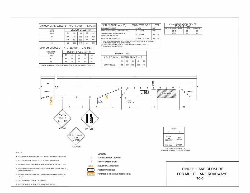
25 35 40 45
250 305 360155 200
1
PCMS
URBAN ARTERIALS & COLLECTORS 35 / 40 MPH 350'
45 MPHURBAN ARTERIALS 500'
25 / 30 MPH 200' (2)
RESIDENTIAL STREETS 25 MPH OR LESS 100' (2)
PCMS
LENGTH (feet)
10105
125
150205 270
165 225
295
180
245
320540
115
2530
35
40
45
10'40
40
SHOULDER
WIDTH
(feet)
120
150
40
60
60
90
90
90
WORK AREA
2
2530
35
40
12
11
LANE
WIDTH
(feet)
8'
1 MILE
AHEAD
LEGEND
TEMPORARY SIGN LOCATION
TRAFFIC SAFETY DRUM
SEQUENTIAL ARROW SIGN
PROTECTIVE VEHICLE
PORTABLE CHANGEABLE MESSAGE SIGN
DESIGN SPEED (MPH)
35/45
25/30
TAPER TANGENT
30
20
60
40
30
COLLECTORS, RESIDENTIAL &
BUSINESS DISTRICTS
(1) ALL SPACING MAY BE ADJUSTED TO ACCOMMODATE, AT-GRADE
INTERSECTIONS AND DRIVEWAYS.
(2) THIS SPACING MAY BE REDUCED IN URBAN AREAS TO FIT
ROADWAY CONDITIONS.
495
450
45
USE A MINIMUM 3 DEVICES TAPER FOR SHOULDER LESS THEN 8'.
RIGHT
LANE
CLOSURE
FIELD LOCATE 1 MILE IN
ADVANCE OF LANE CLOSURE SIGNING.
NOTES:
1.
2.
3.
4.
5.
6.
100'
SEE
NOTE 4
SEE SPECIAL PROVISIONS FOR WORK HOUR RESTRICTIONS.
EXTEND DEVICE TAPER AT L/3 ACROSS SHOULDER.
DEVICES SHALL NOT ENCROACH INTO THE ADJACENT LANE.
USE TRANSVERSE DEVICES IN CLOSED LANE EVERY 1000' (FT)
(RECOMMENDED).
DEVICE SPACING FOR THE DOWNSTREAM TAPER SHALL BE
20' (FT).
ALL SIGNS ARE BLACK ON ORANGE.
REFER TO THE MUTCD FOR SIGN DIMENSIONS.7.
SINGLE-LANE CLOSURE
FOR MULTI-LANE ROADWAYS
TC-3
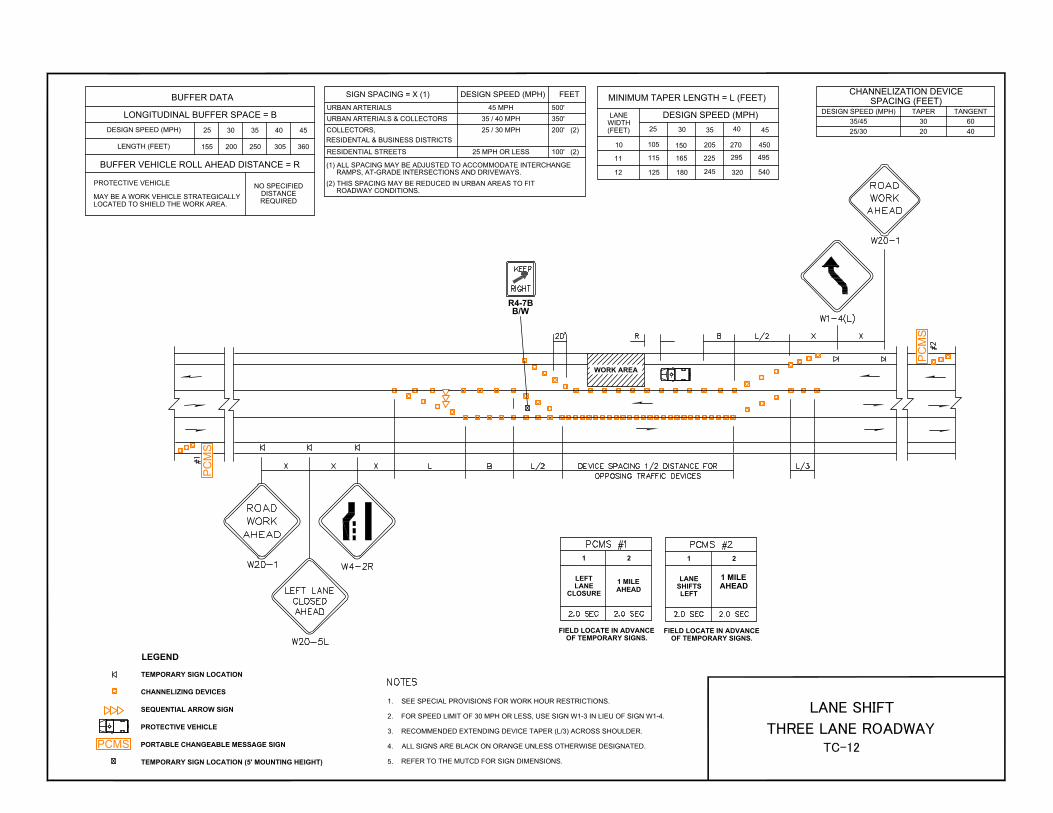
WORK AREA
DESIGN SPEED (MPH)
35/45
25/30
TAPER TANGENT
30
20
60
40
PC
MS
PC
MS
URBAN ARTERIALS & COLLECTORS 35 / 40 MPH 350'
45 MPHURBAN ARTERIALS 500'
25 / 30 MPH 200' (2)
RESIDENTIAL STREETS 25 MPH OR LESS 100' (2)
SIGN SPACING = X (1)
LONGITUDINAL BUFFER SPACE = B
25 30 35 40 45
250 305 360
BUFFER DATA
155 200
BUFFER VEHICLE ROLL AHEAD DISTANCE = R
2530
35
40
45
10
12
11
105
125
150205 270 450
165 225
295 495
180
245
320540
115
MINIMUM TAPER LENGTH = L (FEET)
DESIGN SPEED (MPH)
DESIGN SPEED (MPH)
LENGTH (FEET)
PROTECTIVE VEHICLE
NO SPECIFIED
DISTANCE
REQUIRED
MAY BE A WORK VEHICLE STRATEGICALLY
LOCATED TO SHIELD THE WORK AREA.
(1) ALL SPACING MAY BE ADJUSTED TO ACCOMMODATE INTERCHANGE
RAMPS, AT-GRADE INTERSECTIONS AND DRIVEWAYS.
(2) THIS SPACING MAY BE REDUCED IN URBAN AREAS TO FIT
ROADWAY CONDITIONS.
LANE
WIDTH
(FEET)
CHANNELIZATION DEVICE
SPACING (FEET)
1 2
1 MILE
AHEAD
FIELD LOCATE IN ADVANCE
OF TEMPORARY SIGNS.
1 2
FIELD LOCATE IN ADVANCE
OF TEMPORARY SIGNS.
LEFT
LANE
CLOSURE
LANE
SHIFTS
LEFT
1 MILE
AHEAD
1.
2.
3.
4.
LEGEND
TEMPORARY SIGN LOCATION
CHANNELIZING DEVICES
SEQUENTIAL ARROW SIGN
PROTECTIVE VEHICLE
PORTABLE CHANGEABLE MESSAGE SIGN
TEMPORARY SIGN LOCATION (5' MOUNTING HEIGHT)
PCMS
R4-7B
B/W
SEE SPECIAL PROVISIONS FOR WORK HOUR RESTRICTIONS.
FOR SPEED LIMIT OF 30 MPH OR LESS, USE SIGN W1-3 IN LIEU OF SIGN W1-4.
RECOMMENDED EXTENDING DEVICE TAPER (L/3) ACROSS SHOULDER.
ALL SIGNS ARE BLACK ON ORANGE UNLESS OTHERWISE DESIGNATED.
REFER TO THE MUTCD FOR SIGN DIMENSIONS.
COLLECTORS,
RESIDENTAL & BUSINESS DISTRICTS
5.
DESIGN SPEED (MPH) FEET
LANE SHIFT
THREE LANE ROADWAY
TC-12

OPTIONAL IF 40 MPH OR LESS
DESIGN SPEED (MPH)
35/45
25/30
TAPER TANGENT
30
20
60
40
URBAN ARTERIALS
35 / 40 MPH 350'
45 MPH 500'
25 / 30 MPH 200' (2)
RESIDENTIAL STREETS 25 MPH OR LESS100' (2)
SIGN SPACING = X (1)
LONGITUDINAL BUFFER SPACE = B
DESIGN SPEED (MPH) 25 30 35 40 45
LENGTH (FEET) 250 305 360
BUFFER DATA
155 200
BUFFER VEHICLE ROLL AHEAD DISTANCE = R
2530
35
40
45
10
12
11
105
125
150205 270 450
165 225
295 495
180
245
320540
115
MINIMUM TAPER LENGTH = L (FEET)
DESIGN SPEED (MPH)
PROTECTIVE VEHICLE
1.
2.
3.
4.
5.
LEGEND
FLAGGING STATION
TEMPORARY SIGN LOCATION
CHANNELIZING DEVICES
PROTECTIVE VEHICLE - RECOMMENDED
TEMPORARY SIGN LOCATION (5' MOUNTING HEIGHT)
(1) ALL SPACING MAY BE ADJUSTED TO ACCOMMODATE INTERCHANGE
RAMPS, AT-GRADE INTERSECTIONS AND DRIVEWAYS.
(2) THIS SPACING MAY BE REDUCED IN URBAN AREAS TO FIT
ROADWAY CONDITIONS.
URBAN ARTERIALS, COLLECTORS,
RESIDENTIAL & BUSINESS DISTRICTS
LANE
WIDTH
(FEET)
MAY BE A WORK VEHICLE STRATEGICALLY
LOCATED TO SHIELD THE WORK AREA.
NO SPECIFIED
DISTANCE
REQUIRED
CHANNELIZATION DEVICE
SPACING (FEET)
WORK
AREA
RECOMMEND EXTENDING DEVICE TAPER (L/3) ACROSS SHOULDER.
IF A SIGNAL IS PRESENT, IT SHALL BE SET TO "RED FLASH MODE"
OR TURNED OFF DURING FLAGGING OPERATIONS AND A UNIFORMED
POLICE OFFICER IS REQUIRED.
FOR SPEED LIMIT OF 30 MPH OR LESS USE SIGN W1-3 IN LIEU OF
SIGN W1-4.
MAINTAIN A MINIMUM OF ONE ACCESS POINT FOR EACH BUSINESS
WITHIN WORK AREA LIMITS.
ALL SIGNS ARE BLACK ON ORANGE UNLESS OTHERWISE DESIGNATED.
REFER TO THE MUTCD FOR SIGN DIMENSIONS.6.
DESIGN SPEED (MPH) FEET
INTERSECTION LANE CLOSURE
THREE LANE ROADWAY
TC-14
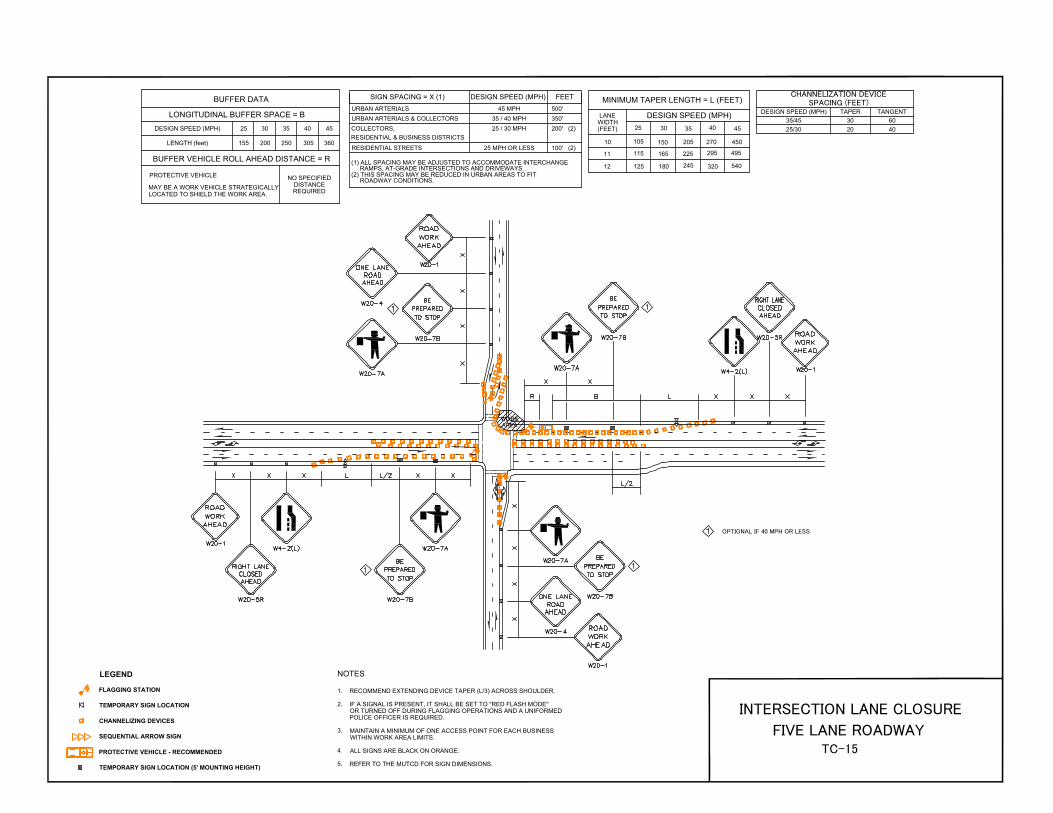
OPTIONAL IF 40 MPH OR LESS
URBAN ARTERIALS & COLLECTORS 35 / 40 MPH 350'
45 MPHURBAN ARTERIALS 500'
25 / 30 MPH 200' (2)
RESIDENTIAL STREETS 25 MPH OR LESS 100' (2)
SIGN SPACING = X (1)
LONGITUDINAL BUFFER SPACE = B
DESIGN SPEED (MPH) 25 30 35 40 45
LENGTH (feet) 250 305 360
BUFFER DATA
155 200
BUFFER VEHICLE ROLL AHEAD DISTANCE = R
2530
35
40
45
10
12
11
105
125
150205 270 450
165 225
295 495
180
245
320540
115
MINIMUM TAPER LENGTH = L (FEET)
DESIGN SPEED (MPH)
PROTECTIVE VEHICLE
DESIGN SPEED (MPH)
35/45
25/30
TAPER TANGENT
30
20
60
40
1.
NOTES
2.
3.
4.
CHANNELIZATION DEVICE
SPACING (FEET)
NO SPECIFIED
DISTANCE
REQUIRED
MAY BE A WORK VEHICLE STRATEGICALLY
LOCATED TO SHIELD THE WORK AREA.
LANE
WIDTH
(FEET)
(1) ALL SPACING MAY BE ADJUSTED TO ACCOMMODATE INTERCHANGE
RAMPS, AT-GRADE INTERSECTIONS AND DRIVEWAYS.
(2) THIS SPACING MAY BE REDUCED IN URBAN AREAS TO FIT
ROADWAY CONDITIONS.
LEGEND
FLAGGING STATION
TEMPORARY SIGN LOCATION
CHANNELIZING DEVICES
SEQUENTIAL ARROW SIGN
PROTECTIVE VEHICLE - RECOMMENDED
TEMPORARY SIGN LOCATION (5' MOUNTING HEIGHT)
WORK
AREA
RECOMMEND EXTENDING DEVICE TAPER (L/3) ACROSS SHOULDER.
IF A SIGNAL IS PRESENT, IT SHALL BE SET TO "RED FLASH MODE"
OR TURNED OFF DURING FLAGGING OPERATIONS AND A UNIFORMED
POLICE OFFICER IS REQUIRED.
MAINTAIN A MINIMUM OF ONE ACCESS POINT FOR EACH BUSINESS
WITHIN WORK AREA LIMITS.
ALL SIGNS ARE BLACK ON ORANGE.
REFER TO THE MUTCD FOR SIGN DIMENSIONS.
COLLECTORS,
RESIDENTIAL & BUSINESS DISTRICTS
5.
DESIGN SPEED (MPH) FEET
INTERSECTION LANE CLOSURE
FIVE LANE ROADWAY
TC-15

R8-3
R/W
SIDEWALK
CLOSED
SIDEWALK CLOSED
AHEAD
WORK AREA
SIDEWALK CLOSED
AHEAD
R9-11
B/W
R9-11
B/W
R9-9
B/W
R9-10
B/W
SIDEWALK CLOSED
R9-10
B/W
SIDEWALK CLOSED
INSTALL ON TYPE 2 BARRICADES THROUGHOUT THE WORK AREA
24 HOURS PRIOR TO IMPLEMENTING TRAFFIC CONTROL.
PRIOR NOTIFICATION OF LOCAL LAW ENFORCEMENT REQUIRED.
1. CONTROLS SHOWN ARE FOR PEDESTRIAN TRAFFIC ONLY.
A 60" PATH WIDTH SHOULD BE MAINTAINED (48" IS THE MINIMUM).
CONTACT AND COORDINATE IMPACTED TRANSIT AGENCIES
PRIOR TO IMPLEMENTING ANY CLOSURES.
SEE SHEET TC-52 FOR TEMPORARY PEDESTRIAN RAMP DETAILS.
ADA PEDESTRIAN FACILITIES MUST BE MAINTAINED. SEE
STANDARD SPECIFICATION 1-10.2(1)B.
TEMPORARY PEDESTRIAN PUSH BUTTONS SHALL BE PLACED ON
THE DIVERTED PATH WHEN EXISTING BUTTONS ARE NOT
ACCESSIBLE TO PEDESTRIANS.
REFER TO THE MUTCD FOR SIGN DIMENSIONS.
2.
3.
4.
5.
6.
LEGEND
TEMPORARY SIGN LOCATION
CHANNELIZING DEVICES
PEDESTRIAN CHANNELIZING DEVICES
TEMPORARY PEDESTRIAN RAMP FOR SIDEWALKS
WORK AREA
7.
INTERSECTION PEDESTRIAN
TRAFFIC CONTROL
TC-16

TYPICAL SECTION A-A
DESIGN SPEED (MPH)
35/45
25/30
TAPER TANGENT
30
20
60
40
LONGITUDINAL BUFFER SPACE = B
PROTECTIVE VEHICLE
DESIGN SPEED (MPH) 25 30 35 40 45
LENGTH (feet) 250 305 360
BUFFER DATA
155 200
BUFFER VEHICLE ROLL AHEAD DISTANCE = R
URBAN ARTERIALS AND COLLECTORS 35 / 40 MPH 350'
45 / 55 MPHURBAN ARTERIALS 500'
25 / 30 MPH 200' (1)
RESIDENTIAL STREETS 25 MPH OR LESS 100' (1)
SIGN SPACING = X (1)
2530
35
40
45
10
12
11
105
125
150205 270 450
165 225
295 495
180
245
320540
115
MINIMUM LANE CLOSURE TAPER LENGTH = L (FEET)
DESIGN SPEED (MPH)
2530
35
40
45
10'
8'
40
40 120
150
MINIMUM SHOULDER TAPER LENGTH = L/3 (FEET)
40
60
60
90
90
90
USE A MINIMUM 3 DEVICES TAPER FOR SHOULDER LESS THEN 8'.
WORK AREA
A
A
NO SPECIFIED
DISTANCE
REQUIRED
LANE
WIDTH
(FEET)
SHOULDER
WIDTH
(FEET)
CHANNELIZATION DEVICE
SPACING (FEET)
(1) THIS SPACING MAY BE REDUCED IN URBAN AREAS TO FIT
ROADWAY CONDITIONS.
COLLECTORS,
RESIDENTIAL & BUSINESS DISTRICTS
1
PCMS
2
1 MILE
AHEAD
RIGHT
LANE
CLOSURE
FIELD LOCATE 1 MILE IN
ADVANCE OF LANE CLOSURE SIGNING.
1.
2.
3.
4.
5.
SEE NOTE 3
100'
PC
MS
BUFFER
SPACE
4'
PCMS
LEGEND
TEMPORARY SIGN LOCATION
CHANNELIZING DEVICES
TRAFFIC SAFETY DRUM
SEQUENTIAL ARROW SIGN
PROTECTIVE VEHICLE
PORTABLE CHANGEABLE MESSAGE SIGN
SEE SPECIAL PROVISIONS FOR WORK HOUR RESTRICTIONS.
RECOMMEND EXTENDING DEVICE TAPER (L/3) ACROSS SHOULDER.
USE TRANSVERSE DEVICES IN CLOSED LANE EVERY 1000' (RECOMMENDED).
ALL SIGNS ARE BLACK ON ORANGE.
RECOMMEND ADVANCE NOTICE FOR ANY OVER WIDTH LOADS PRIOR TO LANE
CLOSURE FOR ALTERNATE ROUTES IF APPLICABLE.
REFER TO THE MUTCD FOR SIGN DIMENSIONS.6.
DESIGN SPEED (MPH) FEET
SINGLE-LANE CLOSURE
WITH SHIFT
TC-17
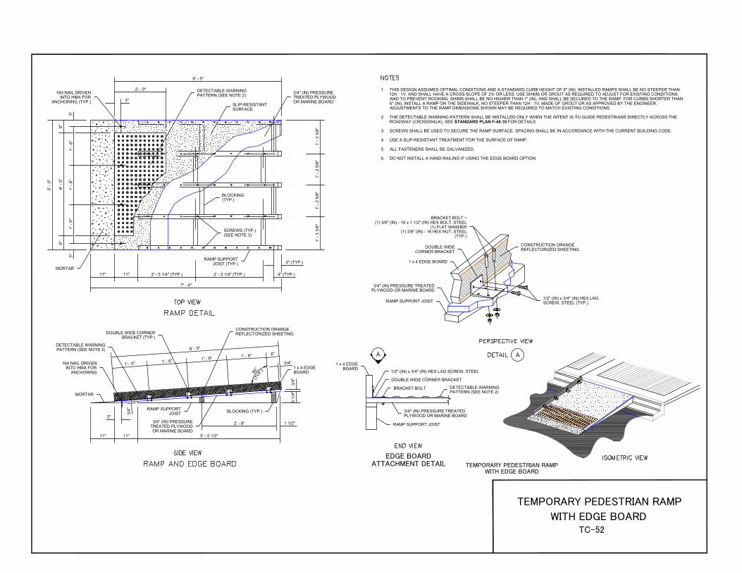
9
0
°
(
T
Y
P
.
)
1. THIS DESIGN ASSUMES OPTIMAL CONDITIONS AND A STANDARD CURB HEIGHT OF 6" (IN). INSTALLED RAMPS SHALL BE NO STEEPER THAN
12H : 1V, AND SHALL HAVE A CROSS-SLOPE OF 2% OR LESS. USE SHIMS OR GROUT AS REQUIRED TO ADJUST FOR EXISTING CONDITIONS
AND TO PREVENT ROCKING. SHIMS SHALL BE NO HIGHER THAN 1" (IN), AND SHALL BE SECURED TO THE RAMP. FOR CURBS SHORTER THAN
6" (IN), INSTALL A RAMP ON THE SIDEWALK, NO STEEPER THAN 12H : 1V, MADE OF GROUT OR AS APPROVED BY THE ENGINEER.
ADJUSTMENTS TO THE RAMP DIMENSIONS SHOWN MAY BE REQUIRED TO MATCH EXISTING CONDITIONS.
THE DETECTABLE WARNING PATTERN SHALL BE INSTALLED ONLY WHEN THE INTENT IS TO GUIDE PEDESTRIANS DIRECTLY ACROSS THE
ROADWAY (CROSSWALK). SEE STANDARD PLAN F-40.10 FOR DETAILS.
SCREWS SHALL BE USED TO SECURE THE RAMP SURFACE. SPACING SHALL BE IN ACCORDANCE WITH THE CURRENT BUILDING CODE.
USE A SLIP-RESISTANT TREATMENT FOR THE SURFACE OF RAMP.
ALL FASTENERS SHALL BE GALVANIZED.
DO NOT INSTALL A HAND RAILING IF USING THE EDGE BOARD OPTION.
2.
3.
4.
5.
6.
TEMPORARY PEDESTRIAN RAMP
WITH EDGE BOARD
EDGE BOARD
ATTACHMENT DETAIL
1 x 4 EDGE
BOARD
SLIP-RESISTANT
SURFACE
BRACKET BOLT ~
(1) 3/8" (IN) - 16 x 1 1/2" (IN) HEX BOLT, STEEL
(1) FLAT WASHER
(1) 3/8" (IN) - 16 HEX NUT, STEEL
(TYP.)
DOUBLE WIDE
CORNER BRACKET
1 x 4 EDGE BOARD
3/4" (IN) PRESSURE TREATED
PLYWOOD OR MARINE BOARD
RAMP SUPPORT JOIST
CONSTRUCTION ORANGE
REFLECTORIZED SHEETING
1/2" (IN) x 3/4" (IN) HEX LAG
SCREW, STEEL (TYP.)
1/2" (IN) x 3/4" (IN) HEX LAG SCREW, STEEL
DOUBLE WIDE CORNER BRACKET
BRACKET BOLT
3/4" (IN) PRESSURE
TREATED PLYWOOD
OR MARINE BOARD
3/4" (IN) PRESSURE TREATED
PLYWOOD OR MARINE BOARD
DETECTABLE WARNING
PATTERN (SEE NOTE 2)
RAMP SUPPORT JOIST
1 x 4 EDGE
BOARD
DETECTABLE WARNING
PATTERN (SEE NOTE 2)
16d NAIL DRIVEN
INTO HMA FOR
ANCHORING (TYP.)
MORTAR
5' - 0"
4' - 0"
6"
6"
1' - 6"
3"
1' - 6"
1' - 6"
3"
3"
6' - 5"
2' - 0"
1' - 3 3/8"
1' - 2 5/8"
1' - 2 5/8"
1' - 3 3/8"
BLOCKING
(TYP.)
SCREWS (TYP.)
(SEE NOTE 3)
7' - 4"
RAMP SUPPORT
JOIST (TYP.)
11" 11" 2' - 5 1/4" (TYP.) 2' - 5 1/4" (TYP.) 4" (TYP.)
3" (TYP.)
DOUBLE WIDE CORNER
BRACKET (TYP.)
DETECTABLE WARNING
PATTERN (SEE NOTE 2)
CONSTRUCTION ORANGE
REFLECTORIZED SHEETING
16d NAIL DRIVEN
INTO HMA FOR
ANCHORING
6' -
5"
1' -
5"
1' -
6"
1' -
6"
1' -
6"
3/4
"
6"
3/4"
RAMP SUPPORT
JOIST
3/4" (IN) PRESSURE
TREATED PLYWOOD
OR MARINE BOARD
BLOCKING (TYP.)
MORTAR
11" 11"
3"
5' - 5 1/2"
2' - 8" 1 1/2"
5 1/4"
3/4"
TEMPORARY PEDESTRIAN RAMP
WITH EDGE BOARD
TC-52

1. ALL HOLES SHOWN SHALL BE DRILLED TO FACILITATE
RE-USE AND FLEXIBLE EXPANSION.
SEE SHEET REFERENCE NO. TC-52, FOR TEMPORARY
PEDESTRIAN RAMP DETAILS.
THIS DESIGN ASSUMES OPTIMAL CONDITIONS AND A
STANDARD CURB HEIGHT OF 6" (IN). INSTALLED RAMPS
SHALL BE NO STEEPER THAN 12H : 1V, AND SHALL HAVE
A CROSS-SLOPE OF 2% OR LESS. USE SHIMS OR GROUT
AS REQUIRED TO ADJUST FOR EXISTING CONDITIONS
AND TO PREVENT ROCKING. SHIMS SHALL BE NO
HIGHER THAN 1" (IN), AND SHALL BE SECURED TO THE
RAMP AND/OR PLATFORM. FOR CURBS SHORTER THAN
6" (IN), INSTALL A RAMP ON THE SIDEWALK, NO STEEPER
THAN 12H : 1V, MADE OF GROUT OR AS APPROVED BY
THE ENGINEER. ADJUSTMENTS TO THE PLATFORM
DIMENSIONS SHOWN MAY BE REQUIRED TO MATCH
EXISTING CONDITIONS.
SCREWS SHALL BE USED TO SECURE THE RAMP
SURFACE. SPACING SHALL BE IN ACCORDANCE WITH
THE CURRENT BUILDING CODE.
USE A SLIP-RESISTANT TREATMENT FOR SURFACE
OF RAMP.
ALL FASTENERS SHALL BE GALVANIZED.
2.
3.
4.
5.
6.
BLOCKING
(TYP.)
TEMPORARY PEDESTRIAN RAMP
TEMPORARY PEDESTRIAN PLATFORM
TEMPORARY PEDESTRIAN RAMP
9/16" (IN) DIAM. HOLES (TYP.) ~
PRE-DRILLED FOR RAIL COLUMN
CONNECTING EYE BOLT
CONNECTING J-HOOK
TEMPORARY PEDESTRIAN
RAMP ~ SEE SHEET
REFERENCE NO WZ-52
TEMPORARY
PEDESTRIAN
PLATFORM
TEMPORARY PEDESTRIAN PLATFORM
CONSTRUCTION ORANGE
REFLECTORIZED SHEETING
CONNECTING EYE BOLT ~
(1) 1/2" (IN) - 13 x 6 EYE BOLT, STEEL
(1) 1 1/2" (IN) FLAT WASHER
(1) 1/2" (IN) - 13 HEX NUT, STEEL
PLATFORM SUPPORT JOIST
3/4" (IN) PRESSURE
TREATED PLYWOOD OR
MARINE BOARD (TYP.)
9/16" (IN) DIAM. HOLES (TYP.) ~
PRE-DRILLED FOR RAIL COLUMN
RAMP SUPPORT JOIST
TEMPORARY PEDESTRIAN RAMP
CONNECTING J-BOLT ~
(1) 1/2" (IN) - 13 x 6 J-BOLT, STEEL
(1) 1 1/2" (IN) FLAT WASHER
(1) 1/2" (IN) - 13 HEX NUT, STEEL
DOUBLE WIDE CORNER BRACKET
WITH 3/8" (IN) - 16 x 1 1/2" (IN) HEX
BOLT, STEEL (TYP.)
1 x 4 EDGE BOARD
1 x 4 EDGE BOARD
CONSTRUCTION ORANGE
REFLECTORIZED SHEETING
1 x 4 EDGE BOARD WITH
CONSTRUCTION ORANGE
REFLECTORIZED SHEETING
3/4" (IN) PRESSURE
TREATED PLYWOOD OR
MARINE BOARD
9/16" (IN) DIAM. HOLES ~
PRE-DRILLED FOR RAIL COLUMN
DOUBLE WIDE CORNER
BRACKET (TYP.)
1 1/2"
3/4"
2 1/2"
1' - 1" 1' - 2" 1' - 2" 1' - 2" 5"
5' - 0"
PRE-DRILLED HOLES
(TYP.) FOR RAILING
ASSEMBLY
SCREWS (TYP.)
(SEE NOTE 3)
2" (TYP.)
5' - 0"
1' - 6 1/2" 2' - 4 1/2" 1' - 1"
SLIP-RESISTANT
SURFACE
3/4" (IN) PRESSURE
TREATED PLYWOOD
OR MARINE BOARD
9"
1' - 2"
1' - 2"
1' - 2"
9"
5" (TYP.)1' - 2"
(TYP.)
1' - 2"
(TYP.)
1' - 2"
(TYP.)
1' - 1"
(TYP.)
1' - 3 1/2"
1' - 2 1/2"
1' - 2 1/2"
1' - 3 1/2"
5' - 0"
TEMPORARY PEDESTRIAN PLATFORM
WITH EDGE BOARD
TC-53

E APPENDIX
ECY 020-87a (Rev. 02/18) Instructions Page
Instructions for Transfer of Coverage Construction Stormwater General Permit
Instructions This form is used to process two types of permit transfers: 1) Complete Transfer, or 2) Partial Transfer. Determine which type of transfer applies to your situation before filling out this form. 1. Complete Transfer: The original permittee has sold, or otherwise released control of the entire siteto another party.
Required Paperwork for Complete Transfer:
• Either the current permittee, or the new permittee(s), must submit a complete and accurateTransfer of Coverage form to Ecology for each new party. The form must be signed by thecurrent permittee and the new permittee.
2. Partial Transfer: The original permittee retains control over some portion of the site after selling orreleasing control over a portion of the site.
Required Paperwork for Partial Transfer
• Either the current permittee or the new permittee(s) must submit a complete and accurateTransfer of Coverage Form for each new operator to Ecology. The form must be signed bythe current permittee and the new permittee.
• For partial transfers, once all transfers are submitted, the original permittee should submitthe Notice of Termination only if the portion(s) they still own or control have undergonefinal stabilization and meet the criteria for termination.
For Your Information
• When this form is 1) completed, 2) signed by the current and new permittee, and 3)submitted to Ecology, permit transfers are effective on the date specified at the top ofpage 1 (unless Ecology notifies the current permittee and new permittee of its intention torevoke coverage under the General Permit or if Ecology sends notice that the application isincomplete). If no date for the transfer of coverage is specified, Ecology will use the date ofthe last signature.
• The new permittee should keep a copy of the signed Transfer of Coverage form (whichserves as proof of permit coverage) until Ecology sends documentation in the mail.
• Following the transfer, the new permittee must either: (1) use the Stormwater PollutionPrevention Plan (SWPPP) developed by the original operator, and modified as necessary,or (2) develop and use a new SWPPP that meets the requirements of the ConstructionStormwater General Permit.
• For projects for which the original permittee has completed a Proposed New Discharge toan Impaired Waterbody Form (ECY 070-399), or for projects that are operating on siteswith soil or groundwater contamination: Upon completion of the Transfer of Coverage form,the new permittee will adopt any special provisions made to protect water quality for sitesthat have existing contamination or that discharge to an impaired waterbody.
To request ADA accommodation including materials in a format for the visually impaired, call the Water Quality Program at 360-407-6600 or visit https://ecology.wa.gov/accessibility. People with impaired hearing may call Washington Relay Service at 711. People with speech disability may call 877-833-6341.
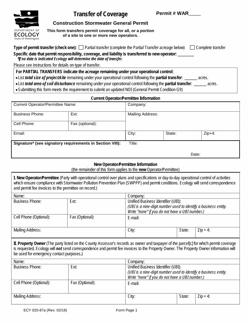
ECY 020-87a (Rev. 02/18) Form Page 1
Transfer of Coverage Construction Stormwater General Permit
This form transfers permit coverage for all, or a portion of a site to one or more new operators.
Permit # WAR
Type of permit transfer (check one): Partial transfer (complete the Partial Transfer acreage below) Complete transfer Specific date that permit responsibility, coverage, and liability is transferred to new operator:
*If no date is indicated Ecology will determine the date of transfer.Please see instructions for details on type of transfer.
For PARTIAL TRANSFERS indicate the acreage remaining under your operational control: • List total size of project/site remaining under your operational control following the partial transfer: acres. • List total area of soil disturbance remaining under your operational control following the partial transfer: acres. • Submitting this form meets the requirement to submit an updated NOI (General Permit Condition G9)
Current Operator/Permittee Information Current Operator/Permittee Name: Company:
Business Phone: Ext: Mailing Address:
Cell Phone: Fax (optional):
Email: City: State: Zip+4:
Signature* (see signatory requirements in Section VIII): Title:
Date:
New Operator/Permittee Information (the remainder of this form applies to the new Operator/Permittee)
I. New Operator/Permittee (Party with operational control over plans and specifications or day-to-day operational control of activities which ensure compliance with Stormwater Pollution Prevention Plan (SWPPP) and permit conditions. Ecology will send correspondence and permit fee invoices to the permittee on record.) Name: Company: Business Phone: Ext: Unified Business Identifier (UBI):
(UBI is a nine-digit number used to identify a business entity. Write “none” if you do not have a UBI number.)
Cell Phone (Optional): Fax (Optional): E-mail:
Mailing Address: City: State: Zip + 4:
II. Property Owner (The party listed on the County Assessor’s records as owner and taxpayer of the parcel[s] for which permit coverageis requested. Ecology will not send correspondence and permit fee invoices to the Property Owner. The Property Owner information will be used for emergency contact purposes.) Name: Company: Business Phone: Ext: Unified Business Identifier (UBI):
(UBI is a nine-digit number used to identify a business entity. Write “none” if you do not have a UBI number.)
Cell Phone (Optional): Fax (Optional): E-mail:
Mailing Address: City: State: Zip + 4:
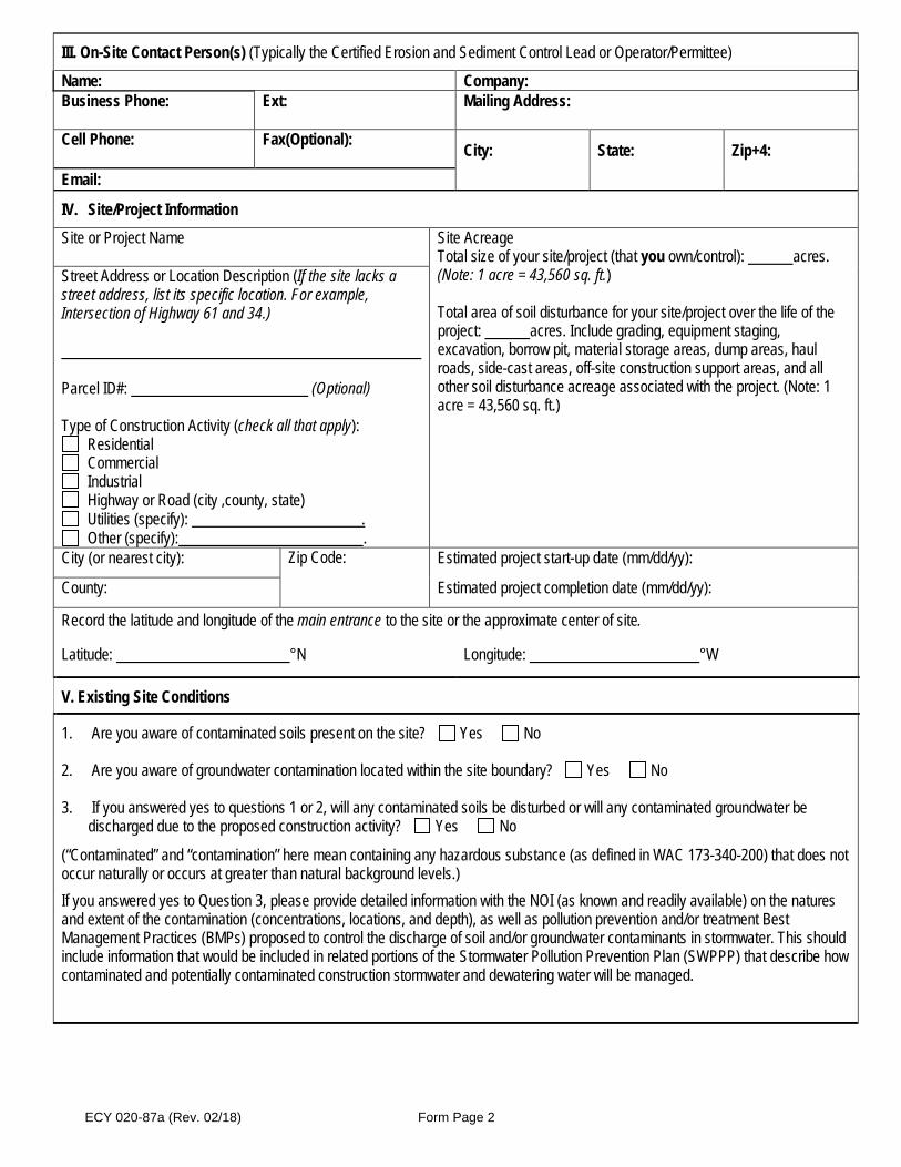
ECY 020-87a (Rev. 02/18) Form Page 2
III. On-Site Contact Person(s) (Typically the Certified Erosion and Sediment Control Lead or Operator/Permittee)
Name: Company: Business Phone: Ext: Mailing Address:
Cell Phone: Fax(Optional): City: State: Zip+4:
Email:
IV. Site/Project InformationSite or Project Name Site Acreage
Total size of your site/project (that you own/control): acres. (Note: 1 acre = 43,560 sq. ft.)
Total area of soil disturbance for your site/project over the life of the project: acres. Include grading, equipment staging, excavation, borrow pit, material storage areas, dump areas, haul roads, side-cast areas, off-site construction support areas, and all other soil disturbance acreage associated with the project. (Note: 1 acre = 43,560 sq. ft.)
Street Address or Location Description (If the site lacks a street address, list its specific location. For example, Intersection of Highway 61 and 34.)
Parcel ID#: (Optional)
Type of Construction Activity (check all that apply): Residential Commercial Industrial Highway or Road (city ,county, state) Utilities (specify): . Other (specify): .
City (or nearest city): Zip Code: Estimated project start-up date (mm/dd/yy):
County: Estimated project completion date (mm/dd/yy):
Record the latitude and longitude of the main entrance to the site or the approximate center of site.
Latitude: °N Longitude: °W
V. Existing Site Conditions
1. Are you aware of contaminated soils present on the site? Yes No
2. Are you aware of groundwater contamination located within the site boundary? Yes No
3. If you answered yes to questions 1 or 2, will any contaminated soils be disturbed or will any contaminated groundwater bedischarged due to the proposed construction activity? Yes No
(“Contaminated” and “contamination” here mean containing any hazardous substance (as defined in WAC 173-340-200) that does not occur naturally or occurs at greater than natural background levels.) If you answered yes to Question 3, please provide detailed information with the NOI (as known and readily available) on the natures and extent of the contamination (concentrations, locations, and depth), as well as pollution prevention and/or treatment Best Management Practices (BMPs) proposed to control the discharge of soil and/or groundwater contaminants in stormwater. This should include information that would be included in related portions of the Stormwater Pollution Prevention Plan (SWPPP) that describe how contaminated and potentially contaminated construction stormwater and dewatering water will be managed.

ECY 020-87a (Rev. 02/18) Form Page 3
VI. WQWebDMR (Electronic Discharge Monitoring Reporting)
You must submit monthly discharge monitoring reports using Ecology’s WQWebDMR system. To sign up for WQWebDMR, or to register a new site, go to https://www.ecology.wa.gov/Regulations-Permits/Guidance-technical-assistance/Water-quality-permits-guidance/WQWebPortal-guidance. If you are unable to submit your DMRs electronically, you may contact Ecology to request a waiver. Ecology will generally only grant waiver requests to those permittees without internet access. Only a permittee or representative, designated in writing, may request access to or a waiver from WQWebDMR. To have the ability to use the system immediately, you must submit the Electronic Signature Agreement with your transfer of coverage form. If you have questions on this process, contact Ecology’s WQWebDMR staff at [email protected] or 800/633-6193 or 360-407-7097 (local). Note: DMRs are optional for permitted sites under 1 acre that do not discharge to impaired waterbodies.
VII. Discharge/Receiving Water Information
Indicate whether your site’s stormwater and/or dewatering water could enter surface waters, directly and/or indirectly: Water will discharge directly or indirectly (through a storm drain system or roadside ditch) into one or more surface waterbodies (wetlands, creeks, lakes, and all other surface waters and water courses).
If your discharge is to a storm sewer system, provide the name of the operator of the storm sewer system: (e.g., City of Tacoma):
Water will discharge to ground with 100% infiltration, with no potential to reach surface waters under any conditions.
If your project includes dewatering, you must include dewatering plans and discharge locations in your site Stormwater Pollution Prevention Plan.
Location of Outfall into Surface Waterbody Enter the outfall identifier code, waterbody name, and latitude/longitude of the point(s) where the site has the potential to discharge into a waterbody (the outfall). Enter all locations. See illustration of Surface Waterbody Outfall locations at the end of this form.
• Include the names and locations of both direct and indirect discharges to surface waterbodies, even if the risk of discharge islow or limited to periods of extreme weather. Attach a separate list if necessary.
• Give each point a unique 1-4 digit alpha numeric code. This code will be used for identifying these points in WQWebDMR.• Some large construction projects (for example, subdivisions, roads, or pipelines) may discharge into several waterbodies.• If the creek or tributary is unnamed, use a format such as “unnamed tributary to Deschutes River.”• If the site discharges to a stormwater conveyance system that in turn flows to a surface waterbody, include the surface
waterbody name and location.
Outfall Identifier Code. These cannot be symbols. (Maximum of 4 characters).
Surface Waterbody Name at the Outfall
Latitude Decimal Degrees
Longitude Decimal Degrees
Example: 001A Example: Puget Sound 47.5289247° N -122.3123550° W ° N ° W
° N ° W
° N ° W
If your site discharges to a waterbody that is on the impaired waterbodies list (e.g., 303[d] list) for turbidity, fine sediment, high pH, or phosphorus, Ecology will require additional documentation before issuing permit coverage and these sites will be subject to additional sampling and numeric effluent limits (per Permit Condition S8). Ecology will notify you if any additional sampling requirements apply. Information on impaired waterbodies is available online at: https://www.ecology.wa.gov/Water-Shorelines/Water-quality/Water-improvement/Assessment-of-state-waters-303d.
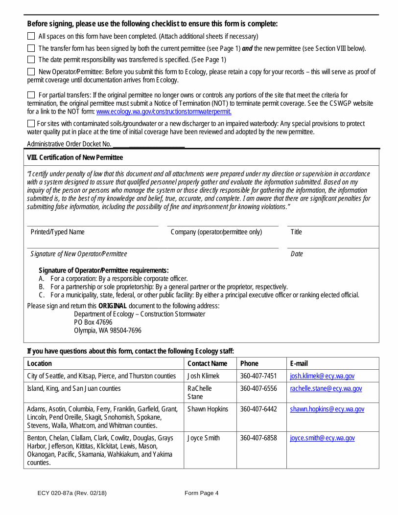
ECY 020-87a (Rev. 02/18) Form Page 4
Before signing, please use the following checklist to ensure this form is complete: All spaces on this form have been completed. (Attach additional sheets if necessary) The transfer form has been signed by both the current permittee (see Page 1) and the new permittee (see Section VIII below). The date permit responsibility was transferred is specified. (See Page 1) New Operator/Permittee: Before you submit this form to Ecology, please retain a copy for your records – this will serve as proof of
permit coverage until documentation arrives from Ecology.
For partial transfers: If the original permittee no longer owns or controls any portions of the site that meet the criteria for termination, the original permittee must submit a Notice of Termination (NOT) to terminate permit coverage. See the CSWGP website for a link to the NOT form: www.ecology.wa.gov/constructionstormwaterpermit.
For sites with contaminated soils/groundwater or a new discharger to an impaired waterbody: Any special provisions to protect water quality put in place at the time of initial coverage have been reviewed and adopted by the new permittee. Administrative Order Docket No. _________________
VIII. Certification of New Permittee
“I certify under penalty of law that this document and all attachments were prepared under my direction or supervision in accordance with a system designed to assure that qualified personnel properly gather and evaluate the information submitted. Based on my inquiry of the person or persons who manage the system or those directly responsible for gathering the information, the information submitted is, to the best of my knowledge and belief, true, accurate, and complete. I am aware that there are significant penalties for submitting false information, including the possibility of fine and imprisonment for knowing violations.”
Printed/Typed Name Company (operator/permittee only) Title
Signature of New Operator/Permittee Date
Signature of Operator/Permittee requirements: A. For a corporation: By a responsible corporate officer. B. For a partnership or sole proprietorship: By a general partner or the proprietor, respectively. C. For a municipality, state, federal, or other public facility: By either a principal executive officer or ranking elected official.
Please sign and return this ORIGINAL document to the following address: Department of Ecology – Construction Stormwater PO Box 47696 Olympia, WA 98504-7696
If you have questions about this form, contact the following Ecology staff: Location Contact Name Phone E-mail City of Seattle, and Kitsap, Pierce, and Thurston counties Josh Klimek 360-407-7451 [email protected] Island, King, and San Juan counties RaChelle
Stane 360-407-6556 [email protected]
Adams, Asotin, Columbia, Ferry, Franklin, Garfield, Grant, Lincoln, Pend Oreille, Skagit, Snohomish, Spokane, Stevens, Walla, Whatcom, and Whitman counties.
Shawn Hopkins 360-407-6442 [email protected]
Benton, Chelan, Clallam, Clark, Cowlitz, Douglas, Grays Harbor, Jefferson, Kittitas, Klickitat, Lewis, Mason, Okanogan, Pacific, Skamania, Wahkiakum, and Yakima counties.
Joyce Smith 360-407-6858 [email protected]


F WAGE RATES
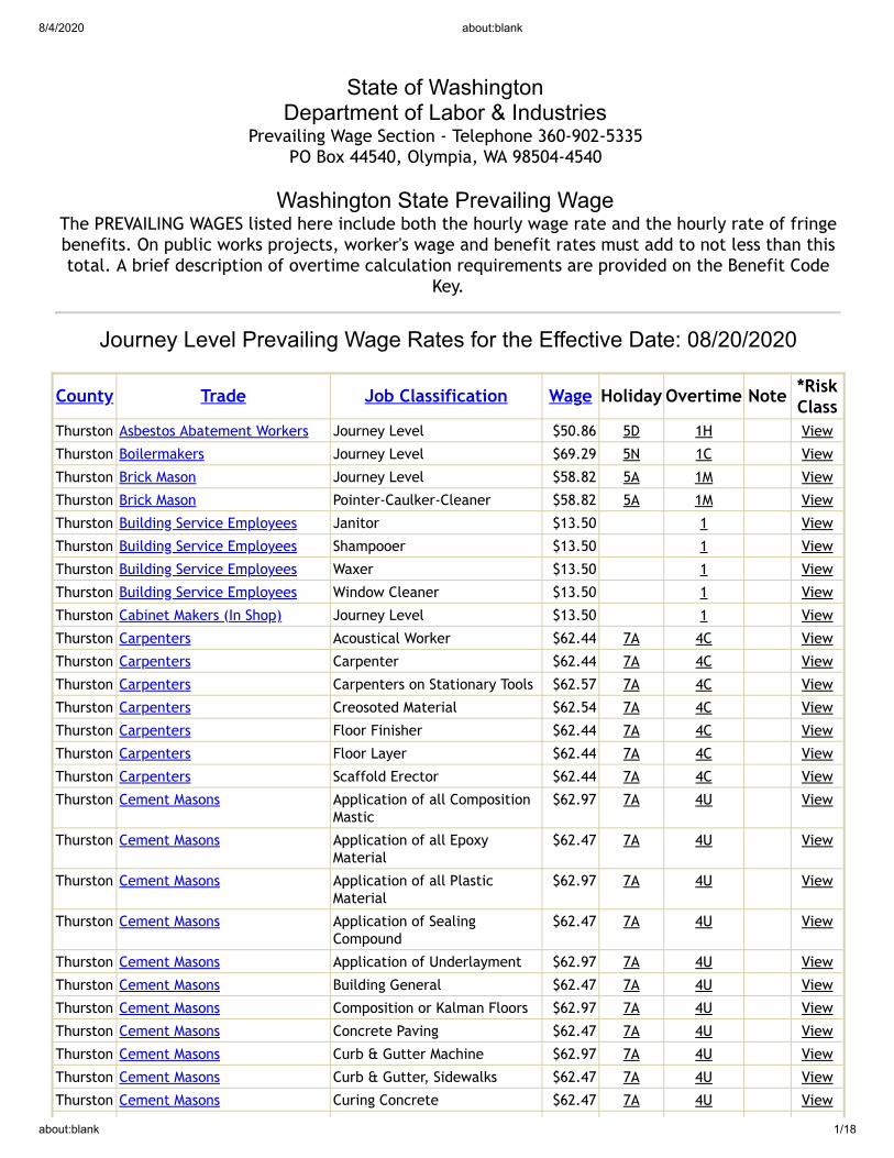
8/4/2020 about:blank
about:blank 1/18
State of Washington Department of Labor & Industries
Prevailing Wage Section - Telephone 360-902-5335 PO Box 44540, Olympia, WA 98504-4540
Washington State Prevailing Wage The PREVAILING WAGES listed here include both the hourly wage rate and the hourly rate of fringebenefits. On public works projects, worker's wage and benefit rates must add to not less than thistotal. A brief description of overtime calculation requirements are provided on the Benefit Code
Key.
Journey Level Prevailing Wage Rates for the Effective Date: 08/20/2020
County Trade Job Classification Wage Holiday Overtime Note *RiskClass
Thurston Asbestos Abatement Workers Journey Level $50.86 5D 1H View
Thurston Boilermakers Journey Level $69.29 5N 1C View
Thurston Brick Mason Journey Level $58.82 5A 1M View
Thurston Brick Mason Pointer-Caulker-Cleaner $58.82 5A 1M View
Thurston Building Service Employees Janitor $13.50 1 View
Thurston Building Service Employees Shampooer $13.50 1 View
Thurston Building Service Employees Waxer $13.50 1 View
Thurston Building Service Employees Window Cleaner $13.50 1 View
Thurston Cabinet Makers (In Shop) Journey Level $13.50 1 View
Thurston Carpenters Acoustical Worker $62.44 7A 4C View
Thurston Carpenters Carpenter $62.44 7A 4C View
Thurston Carpenters Carpenters on Stationary Tools $62.57 7A 4C View
Thurston Carpenters Creosoted Material $62.54 7A 4C View
Thurston Carpenters Floor Finisher $62.44 7A 4C View
Thurston Carpenters Floor Layer $62.44 7A 4C View
Thurston Carpenters Scaffold Erector $62.44 7A 4C View
Thurston Cement Masons Application of all CompositionMastic
$62.97 7A 4U View
Thurston Cement Masons Application of all EpoxyMaterial
$62.47 7A 4U View
Thurston Cement Masons Application of all PlasticMaterial
$62.97 7A 4U View
Thurston Cement Masons Application of SealingCompound
$62.47 7A 4U View
Thurston Cement Masons Application of Underlayment $62.97 7A 4U View
Thurston Cement Masons Building General $62.47 7A 4U View
Thurston Cement Masons Composition or Kalman Floors $62.97 7A 4U View
Thurston Cement Masons Concrete Paving $62.47 7A 4U View
Thurston Cement Masons Curb & Gutter Machine $62.97 7A 4U View
Thurston Cement Masons Curb & Gutter, Sidewalks $62.47 7A 4U View
Thurston Cement Masons Curing Concrete $62.47 7A 4U View
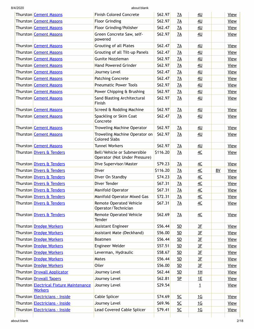
8/4/2020 about:blank
about:blank 2/18
Thurston Cement Masons Finish Colored Concrete $62.97 7A 4U View
Thurston Cement Masons Floor Grinding $62.97 7A 4U View
Thurston Cement Masons Floor Grinding/Polisher $62.47 7A 4U View
Thurston Cement Masons Green Concrete Saw, self-powered
$62.97 7A 4U View
Thurston Cement Masons Grouting of all Plates $62.47 7A 4U View
Thurston Cement Masons Grouting of all Tilt-up Panels $62.47 7A 4U View
Thurston Cement Masons Gunite Nozzleman $62.97 7A 4U View
Thurston Cement Masons Hand Powered Grinder $62.97 7A 4U View
Thurston Cement Masons Journey Level $62.47 7A 4U View
Thurston Cement Masons Patching Concrete $62.47 7A 4U View
Thurston Cement Masons Pneumatic Power Tools $62.97 7A 4U View
Thurston Cement Masons Power Chipping & Brushing $62.97 7A 4U View
Thurston Cement Masons Sand Blasting ArchitecturalFinish
$62.97 7A 4U View
Thurston Cement Masons Screed & Rodding Machine $62.97 7A 4U View
Thurston Cement Masons Spackling or Skim CoatConcrete
$62.47 7A 4U View
Thurston Cement Masons Troweling Machine Operator $62.97 7A 4U View
Thurston Cement Masons Troweling Machine Operator onColored Slabs
$62.97 7A 4U View
Thurston Cement Masons Tunnel Workers $62.97 7A 4U View
Thurston Divers & Tenders Bell/Vehicle or SubmersibleOperator (Not Under Pressure)
$116.20 7A 4C View
Thurston Divers & Tenders Dive Supervisor/Master $79.23 7A 4C View
Thurston Divers & Tenders Diver $116.20 7A 4C 8V View
Thurston Divers & Tenders Diver On Standby $74.23 7A 4C View
Thurston Divers & Tenders Diver Tender $67.31 7A 4C View
Thurston Divers & Tenders Manifold Operator $67.31 7A 4C View
Thurston Divers & Tenders Manifold Operator Mixed Gas $72.31 7A 4C View
Thurston Divers & Tenders Remote Operated VehicleOperator/Technician
$67.31 7A 4C View
Thurston Divers & Tenders Remote Operated VehicleTender
$62.69 7A 4C View
Thurston Dredge Workers Assistant Engineer $56.44 5D 3F View
Thurston Dredge Workers Assistant Mate (Deckhand) $56.00 5D 3F View
Thurston Dredge Workers Boatmen $56.44 5D 3F View
Thurston Dredge Workers Engineer Welder $57.51 5D 3F View
Thurston Dredge Workers Leverman, Hydraulic $58.67 5D 3F View
Thurston Dredge Workers Mates $56.44 5D 3F View
Thurston Dredge Workers Oiler $56.00 5D 3F View
Thurston Drywall Applicator Journey Level $62.44 5D 1H View
Thurston Drywall Tapers Journey Level $62.81 5P 1E View
Thurston Electrical Fixture MaintenanceWorkers
Journey Level $29.54 1 View
Thurston Electricians - Inside Cable Splicer $74.69 5C 1G View
Thurston Electricians - Inside Journey Level $69.96 5C 1G View
Thurston Electricians - Inside Lead Covered Cable Splicer $79.41 5C 1G View
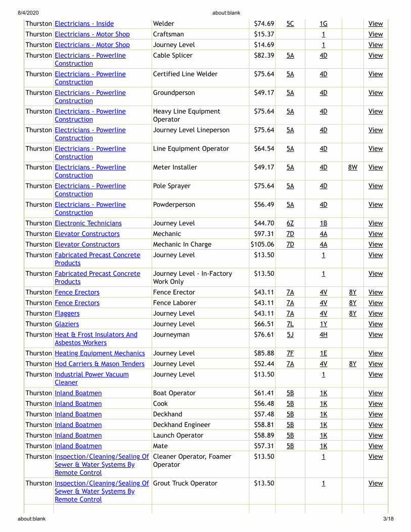
8/4/2020 about:blank
about:blank 3/18
Thurston Electricians - Inside Welder $74.69 5C 1G View
Thurston Electricians - Motor Shop Craftsman $15.37 1 View
Thurston Electricians - Motor Shop Journey Level $14.69 1 View
Thurston Electricians - PowerlineConstruction
Cable Splicer $82.39 5A 4D View
Thurston Electricians - PowerlineConstruction
Certified Line Welder $75.64 5A 4D View
Thurston Electricians - PowerlineConstruction
Groundperson $49.17 5A 4D View
Thurston Electricians - PowerlineConstruction
Heavy Line EquipmentOperator
$75.64 5A 4D View
Thurston Electricians - PowerlineConstruction
Journey Level Lineperson $75.64 5A 4D View
Thurston Electricians - PowerlineConstruction
Line Equipment Operator $64.54 5A 4D View
Thurston Electricians - PowerlineConstruction
Meter Installer $49.17 5A 4D 8W View
Thurston Electricians - PowerlineConstruction
Pole Sprayer $75.64 5A 4D View
Thurston Electricians - PowerlineConstruction
Powderperson $56.49 5A 4D View
Thurston Electronic Technicians Journey Level $44.70 6Z 1B View
Thurston Elevator Constructors Mechanic $97.31 7D 4A View
Thurston Elevator Constructors Mechanic In Charge $105.06 7D 4A View
Thurston Fabricated Precast ConcreteProducts
Journey Level $13.50 1 View
Thurston Fabricated Precast ConcreteProducts
Journey Level - In-FactoryWork Only
$13.50 1 View
Thurston Fence Erectors Fence Erector $43.11 7A 4V 8Y View
Thurston Fence Erectors Fence Laborer $43.11 7A 4V 8Y View
Thurston Flaggers Journey Level $43.11 7A 4V 8Y View
Thurston Glaziers Journey Level $66.51 7L 1Y View
Thurston Heat & Frost Insulators AndAsbestos Workers
Journeyman $76.61 5J 4H View
Thurston Heating Equipment Mechanics Journey Level $85.88 7F 1E View
Thurston Hod Carriers & Mason Tenders Journey Level $52.44 7A 4V 8Y View
Thurston Industrial Power VacuumCleaner
Journey Level $13.50 1 View
Thurston Inland Boatmen Boat Operator $61.41 5B 1K View
Thurston Inland Boatmen Cook $56.48 5B 1K View
Thurston Inland Boatmen Deckhand $57.48 5B 1K View
Thurston Inland Boatmen Deckhand Engineer $58.81 5B 1K View
Thurston Inland Boatmen Launch Operator $58.89 5B 1K View
Thurston Inland Boatmen Mate $57.31 5B 1K View
Thurston Inspection/Cleaning/Sealing OfSewer & Water Systems ByRemote Control
Cleaner Operator, FoamerOperator
$13.50 1 View
Thurston Inspection/Cleaning/Sealing OfSewer & Water Systems ByRemote Control
Grout Truck Operator $13.50 1 View

8/4/2020 about:blank
about:blank 4/18
Thurston Inspection/Cleaning/Sealing OfSewer & Water Systems ByRemote Control
Head Operator $13.50 1 View
Thurston Inspection/Cleaning/Sealing OfSewer & Water Systems ByRemote Control
Technician $25.00 1 View
Thurston Inspection/Cleaning/Sealing OfSewer & Water Systems ByRemote Control
Tv Truck Operator $13.50 1 View
Thurston Insulation Applicators Journey Level $62.44 7A 4C View
Thurston Ironworkers Journeyman $73.73 7N 1O View
Thurston Laborers Air, Gas Or Electric VibratingScreed
$50.86 7A 4V 8Y View
Thurston Laborers Airtrac Drill Operator $52.44 7A 4V 8Y View
Thurston Laborers Ballast Regular Machine $50.86 7A 4V 8Y View
Thurston Laborers Batch Weighman $43.11 7A 4V 8Y View
Thurston Laborers Brick Pavers $50.86 7A 4V 8Y View
Thurston Laborers Brush Cutter $50.86 7A 4V 8Y View
Thurston Laborers Brush Hog Feeder $50.86 7A 4V 8Y View
Thurston Laborers Burner $50.86 7A 4V 8Y View
Thurston Laborers Caisson Worker $52.44 7A 4V 8Y View
Thurston Laborers Carpenter Tender $50.86 7A 4V 8Y View
Thurston Laborers Cement Dumper-paving $51.80 7A 4V 8Y View
Thurston Laborers Cement Finisher Tender $50.86 7A 4V 8Y View
Thurston Laborers Change House Or Dry Shack $50.86 7A 4V 8Y View
Thurston Laborers Chipping Gun (30 Lbs. AndOver)
$51.80 7A 4V 8Y View
Thurston Laborers Chipping Gun (Under 30 Lbs.) $50.86 7A 4V 8Y View
Thurston Laborers Choker Setter $50.86 7A 4V 8Y View
Thurston Laborers Chuck Tender $50.86 7A 4V 8Y View
Thurston Laborers Clary Power Spreader $51.80 7A 4V 8Y View
Thurston Laborers Clean-up Laborer $50.86 7A 4V 8Y View
Thurston Laborers Concrete Dumper/ChuteOperator
$51.80 7A 4V 8Y View
Thurston Laborers Concrete Form Stripper $50.86 7A 4V 8Y View
Thurston Laborers Concrete Placement Crew $51.80 7A 4V 8Y View
Thurston Laborers Concrete Saw Operator/CoreDriller
$51.80 7A 4V 8Y View
Thurston Laborers Crusher Feeder $43.11 7A 4V 8Y View
Thurston Laborers Curing Laborer $50.86 7A 4V 8Y View
Thurston Laborers Demolition: Wrecking & Moving(Incl. Charred Material)
$50.86 7A 4V 8Y View
Thurston Laborers Ditch Digger $50.86 7A 4V 8Y View
Thurston Laborers Diver $52.44 7A 4V 8Y View
Thurston Laborers Drill Operator (Hydraulic,Diamond)
$51.80 7A 4V 8Y View
Thurston Laborers Dry Stack Walls $50.86 7A 4V 8Y View
Thurston Laborers Dump Person $50.86 7A 4V 8Y View
Thurston Laborers Epoxy Technician $50.86 7A 4V 8Y View
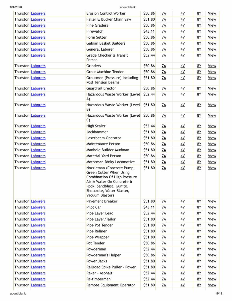
8/4/2020 about:blank
about:blank 5/18
Thurston Laborers Erosion Control Worker $50.86 7A 4V 8Y View
Thurston Laborers Faller & Bucker Chain Saw $51.80 7A 4V 8Y View
Thurston Laborers Fine Graders $50.86 7A 4V 8Y View
Thurston Laborers Firewatch $43.11 7A 4V 8Y View
Thurston Laborers Form Setter $50.86 7A 4V 8Y View
Thurston Laborers Gabian Basket Builders $50.86 7A 4V 8Y View
Thurston Laborers General Laborer $50.86 7A 4V 8Y View
Thurston Laborers Grade Checker & TransitPerson
$52.44 7A 4V 8Y View
Thurston Laborers Grinders $50.86 7A 4V 8Y View
Thurston Laborers Grout Machine Tender $50.86 7A 4V 8Y View
Thurston Laborers Groutmen (Pressure) IncludingPost Tension Beams
$51.80 7A 4V 8Y View
Thurston Laborers Guardrail Erector $50.86 7A 4V 8Y View
Thurston Laborers Hazardous Waste Worker (LevelA)
$52.44 7A 4V 8Y View
Thurston Laborers Hazardous Waste Worker (LevelB)
$51.80 7A 4V 8Y View
Thurston Laborers Hazardous Waste Worker (LevelC)
$50.86 7A 4V 8Y View
Thurston Laborers High Scaler $52.44 7A 4V 8Y View
Thurston Laborers Jackhammer $51.80 7A 4V 8Y View
Thurston Laborers Laserbeam Operator $51.80 7A 4V 8Y View
Thurston Laborers Maintenance Person $50.86 7A 4V 8Y View
Thurston Laborers Manhole Builder-Mudman $51.80 7A 4V 8Y View
Thurston Laborers Material Yard Person $50.86 7A 4V 8Y View
Thurston Laborers Motorman-Dinky Locomotive $51.80 7A 4V 8Y View
Thurston Laborers Nozzleman (Concrete Pump,Green Cutter When UsingCombination Of High PressureAir & Water On Concrete &Rock, Sandblast, Gunite,Shotcrete, Water Blaster,Vacuum Blaster)
$51.80 7A 4V 8Y View
Thurston Laborers Pavement Breaker $51.80 7A 4V 8Y View
Thurston Laborers Pilot Car $43.11 7A 4V 8Y View
Thurston Laborers Pipe Layer Lead $52.44 7A 4V 8Y View
Thurston Laborers Pipe Layer/Tailor $51.80 7A 4V 8Y View
Thurston Laborers Pipe Pot Tender $51.80 7A 4V 8Y View
Thurston Laborers Pipe Reliner $51.80 7A 4V 8Y View
Thurston Laborers Pipe Wrapper $51.80 7A 4V 8Y View
Thurston Laborers Pot Tender $50.86 7A 4V 8Y View
Thurston Laborers Powderman $52.44 7A 4V 8Y View
Thurston Laborers Powderman's Helper $50.86 7A 4V 8Y View
Thurston Laborers Power Jacks $51.80 7A 4V 8Y View
Thurston Laborers Railroad Spike Puller - Power $51.80 7A 4V 8Y View
Thurston Laborers Raker - Asphalt $52.44 7A 4V 8Y View
Thurston Laborers Re-timberman $52.44 7A 4V 8Y View
Thurston Laborers Remote Equipment Operator $51.80 7A 4V 8Y View

8/4/2020 about:blank
about:blank 6/18
Thurston Laborers Rigger/Signal Person $51.80 7A 4V 8Y View
Thurston Laborers Rip Rap Person $50.86 7A 4V 8Y View
Thurston Laborers Rivet Buster $51.80 7A 4V 8Y View
Thurston Laborers Rodder $51.80 7A 4V 8Y View
Thurston Laborers Scaffold Erector $50.86 7A 4V 8Y View
Thurston Laborers Scale Person $50.86 7A 4V 8Y View
Thurston Laborers Sloper (Over 20") $51.80 7A 4V 8Y View
Thurston Laborers Sloper Sprayer $50.86 7A 4V 8Y View
Thurston Laborers Spreader (Concrete) $51.80 7A 4V 8Y View
Thurston Laborers Stake Hopper $50.86 7A 4V 8Y View
Thurston Laborers Stock Piler $50.86 7A 4V 8Y View
Thurston Laborers Swinging Stage/BoatswainChair
$43.11 7A 4V 8Y View
Thurston Laborers Tamper & Similar Electric, Air& Gas Operated Tools
$51.80 7A 4V 8Y View
Thurston Laborers Tamper (Multiple & Self-propelled)
$51.80 7A 4V 8Y View
Thurston Laborers Timber Person - Sewer (Lagger,Shorer & Cribber)
$51.80 7A 4V 8Y View
Thurston Laborers Toolroom Person (at Jobsite) $50.86 7A 4V 8Y View
Thurston Laborers Topper $50.86 7A 4V 8Y View
Thurston Laborers Track Laborer $50.86 7A 4V 8Y View
Thurston Laborers Track Liner (Power) $51.80 7A 4V 8Y View
Thurston Laborers Traffic Control Laborer $46.10 7A 4V 9C View
Thurston Laborers Traffic Control Supervisor $48.84 7A 4V 9C View
Thurston Laborers Truck Spotter $50.86 7A 4V 8Y View
Thurston Laborers Tugger Operator $51.80 7A 4V 8Y View
Thurston Laborers Tunnel Work-Compressed AirWorker 0-30 psi
$120.61 7A 4V 9B View
Thurston Laborers Tunnel Work-Compressed AirWorker 30.01-44.00 psi
$125.64 7A 4V 9B View
Thurston Laborers Tunnel Work-Compressed AirWorker 44.01-54.00 psi
$129.32 7A 4V 9B View
Thurston Laborers Tunnel Work-Compressed AirWorker 54.01-60.00 psi
$135.02 7A 4V 9B View
Thurston Laborers Tunnel Work-Compressed AirWorker 60.01-64.00 psi
$137.14 7A 4V 9B View
Thurston Laborers Tunnel Work-Compressed AirWorker 64.01-68.00 psi
$142.24 7A 4V 9B View
Thurston Laborers Tunnel Work-Compressed AirWorker 68.01-70.00 psi
$144.14 7A 4V 9B View
Thurston Laborers Tunnel Work-Compressed AirWorker 70.01-72.00 psi
$146.14 7A 4V 9B View
Thurston Laborers Tunnel Work-Compressed AirWorker 72.01-74.00 psi
$148.14 7A 4V 9B View
Thurston Laborers Tunnel Work-Guage and LockTender
$52.54 7A 4V 8Y View
Thurston Laborers Tunnel Work-Miner $52.54 7A 4V 8Y View
Thurston Laborers Vibrator $51.80 7A 4V 8Y View
Thurston Laborers Vinyl Seamer $50.86 7A 4V 8Y View
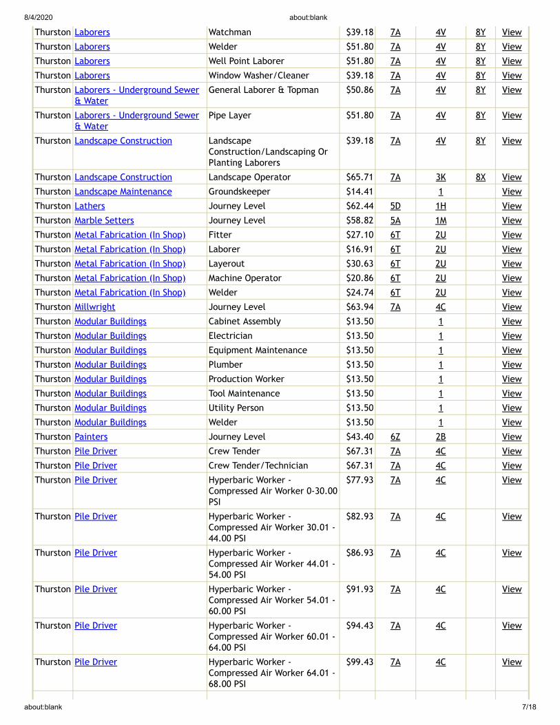
8/4/2020 about:blank
about:blank 7/18
Thurston Laborers Watchman $39.18 7A 4V 8Y View
Thurston Laborers Welder $51.80 7A 4V 8Y View
Thurston Laborers Well Point Laborer $51.80 7A 4V 8Y View
Thurston Laborers Window Washer/Cleaner $39.18 7A 4V 8Y View
Thurston Laborers - Underground Sewer& Water
General Laborer & Topman $50.86 7A 4V 8Y View
Thurston Laborers - Underground Sewer& Water
Pipe Layer $51.80 7A 4V 8Y View
Thurston Landscape Construction LandscapeConstruction/Landscaping OrPlanting Laborers
$39.18 7A 4V 8Y View
Thurston Landscape Construction Landscape Operator $65.71 7A 3K 8X View
Thurston Landscape Maintenance Groundskeeper $14.41 1 View
Thurston Lathers Journey Level $62.44 5D 1H View
Thurston Marble Setters Journey Level $58.82 5A 1M View
Thurston Metal Fabrication (In Shop) Fitter $27.10 6T 2U View
Thurston Metal Fabrication (In Shop) Laborer $16.91 6T 2U View
Thurston Metal Fabrication (In Shop) Layerout $30.63 6T 2U View
Thurston Metal Fabrication (In Shop) Machine Operator $20.86 6T 2U View
Thurston Metal Fabrication (In Shop) Welder $24.74 6T 2U View
Thurston Millwright Journey Level $63.94 7A 4C View
Thurston Modular Buildings Cabinet Assembly $13.50 1 View
Thurston Modular Buildings Electrician $13.50 1 View
Thurston Modular Buildings Equipment Maintenance $13.50 1 View
Thurston Modular Buildings Plumber $13.50 1 View
Thurston Modular Buildings Production Worker $13.50 1 View
Thurston Modular Buildings Tool Maintenance $13.50 1 View
Thurston Modular Buildings Utility Person $13.50 1 View
Thurston Modular Buildings Welder $13.50 1 View
Thurston Painters Journey Level $43.40 6Z 2B View
Thurston Pile Driver Crew Tender $67.31 7A 4C View
Thurston Pile Driver Crew Tender/Technician $67.31 7A 4C View
Thurston Pile Driver Hyperbaric Worker -Compressed Air Worker 0-30.00PSI
$77.93 7A 4C View
Thurston Pile Driver Hyperbaric Worker -Compressed Air Worker 30.01 -44.00 PSI
$82.93 7A 4C View
Thurston Pile Driver Hyperbaric Worker -Compressed Air Worker 44.01 -54.00 PSI
$86.93 7A 4C View
Thurston Pile Driver Hyperbaric Worker -Compressed Air Worker 54.01 -60.00 PSI
$91.93 7A 4C View
Thurston Pile Driver Hyperbaric Worker -Compressed Air Worker 60.01 -64.00 PSI
$94.43 7A 4C View
Thurston Pile Driver Hyperbaric Worker -Compressed Air Worker 64.01 -68.00 PSI
$99.43 7A 4C View

8/4/2020 about:blank
about:blank 8/18
Thurston Pile Driver Hyperbaric Worker -Compressed Air Worker 68.01 -70.00 PSI
$101.43 7A 4C View
Thurston Pile Driver Hyperbaric Worker -Compressed Air Worker 70.01 -72.00 PSI
$103.43 7A 4C View
Thurston Pile Driver Hyperbaric Worker -Compressed Air Worker 72.01 -74.00 PSI
$105.43 7A 4C View
Thurston Pile Driver Journey Level $62.69 7A 4C View
Thurston Plasterers Journey Level $59.29 7Q 1R View
Thurston Playground & Park EquipmentInstallers
Journey Level $13.50 1 View
Thurston Plumbers & Pipefitters Journey Level $76.22 5A 1G View
Thurston Power Equipment Operators Asphalt Plant Operator $66.81 7A 3K 8X View
Thurston Power Equipment Operators Assistant Engineers $62.85 7A 3K 8X View
Thurston Power Equipment Operators Barrier Machine (zipper) $66.22 7A 3K 8X View
Thurston Power Equipment Operators Batch Plant Operator:Concrete
$66.22 7A 3K 8X View
Thurston Power Equipment Operators Bobcat $62.85 7A 3K 8X View
Thurston Power Equipment Operators Brokk - Remote DemolitionEquipment
$62.85 7A 3K 8X View
Thurston Power Equipment Operators Brooms $62.85 7A 3K 8X View
Thurston Power Equipment Operators Bump Cutter $66.22 7A 3K 8X View
Thurston Power Equipment Operators Cableways $66.81 7A 3K 8X View
Thurston Power Equipment Operators Chipper $66.22 7A 3K 8X View
Thurston Power Equipment Operators Compressor $62.85 7A 3K 8X View
Thurston Power Equipment Operators Concrete Pump: Truck MountWith Boom Attachment Over42m
$66.81 7A 3K 8X View
Thurston Power Equipment Operators Concrete Finish Machine -laserScreed
$62.85 7A 3K 8X View
Thurston Power Equipment Operators Concrete Pump - Mounted OrTrailer High Pressure LinePump, Pump High Pressure
$65.71 7A 3K 8X View
Thurston Power Equipment Operators Concrete Pump: Truck MountWith Boom Attachment Up To42m
$66.22 7A 3K 8X View
Thurston Power Equipment Operators Conveyors $65.71 7A 3K 8X View
Thurston Power Equipment Operators Cranes, 100 Tons - 199 Tons, Or150 Ft Of Boom (including JibWith Attachments)
$67.49 7A 3K 8X View
Thurston Power Equipment Operators Cranes: 20 Tons Through 44Tons With Attachments
$66.22 7A 3K 8X View
Thurston Power Equipment Operators Cranes: 200 tons to 299 tons,or 250' of boom (including jibwith attachments)
$68.17 7A 3K 8X View
Thurston Power Equipment Operators Cranes: 300 tons and over, or300' of boom (including jibwith attachments)
$68.84 7A 3K 8X View
Thurston Power Equipment Operators Cranes: 45 Tons Through 99Tons, Under 150' Of Boom
$66.81 7A 3K 8X View

8/4/2020 about:blank
about:blank 9/18
(including Jib WithAttachments)
Thurston Power Equipment Operators Cranes: A-frame - 10 Tons AndUnder
$62.85 7A 3K 8X View
Thurston Power Equipment Operators Cranes: Friction 200 tons andover. Tower Cranes: over 250'in height from base to boom.
$68.84 7A 3K 8X View
Thurston Power Equipment Operators Cranes: Friction cranesthrough 199 tons
$68.17 7A 3K 8X View
Thurston Power Equipment Operators Cranes: Through 19 Tons WithAttachments A-frame Over 10Tons
$65.71 7A 3K 8X View
Thurston Power Equipment Operators Crusher $66.22 7A 3K 8X View
Thurston Power Equipment Operators Deck Engineer/deck Winches(power)
$66.22 7A 3K 8X View
Thurston Power Equipment Operators Derricks, On Building Work $66.81 7A 3K 8X View
Thurston Power Equipment Operators Dozers D-9 & Under $65.71 7A 3K 8X View
Thurston Power Equipment Operators Drill Oilers: Auger Type, TruckOr Crane Mount
$65.71 7A 3K 8X View
Thurston Power Equipment Operators Drilling Machine $67.49 7A 3K 8X View
Thurston Power Equipment Operators Elevator And Man-lift:Permanent And Shaft Type
$62.85 7A 3K 8X View
Thurston Power Equipment Operators Finishing Machine, Bidwell AndGamaco & Similar Equipment
$66.22 7A 3K 8X View
Thurston Power Equipment Operators Forklift: 3000 Lbs And OverWith Attachments
$65.71 7A 3K 8X View
Thurston Power Equipment Operators Forklifts: Under 3000 Lbs. WithAttachments
$62.85 7A 3K 8X View
Thurston Power Equipment Operators Grade Engineer: UsingBlueprints, Cut Sheets,etc.
$66.22 7A 3K 8X View
Thurston Power Equipment Operators Gradechecker/stakeman $62.85 7A 3K 8X View
Thurston Power Equipment Operators Guardrail punch/Auger $66.22 7A 3K 8X View
Thurston Power Equipment Operators Hard Tail End DumpArticulating Off- RoadEquipment 45 Yards. & Over
$66.81 7A 3K 8X View
Thurston Power Equipment Operators Hard Tail End DumpArticulating Off-roadEquipment Under 45 Yards
$66.22 7A 3K 8X View
Thurston Power Equipment Operators Horizontal/directional DrillLocator
$65.71 7A 3K 8X View
Thurston Power Equipment Operators Horizontal/directional DrillOperator
$66.22 7A 3K 8X View
Thurston Power Equipment Operators Hydralifts/Boom Trucks Over10 Tons
$65.71 7A 3K 8X View
Thurston Power Equipment Operators Hydralifts/boom Trucks, 10Tons And Under
$62.85 7A 3K 8X View
Thurston Power Equipment Operators Loader, Overhead 8 Yards. &Over
$67.49 7A 3K 8X View
Thurston Power Equipment Operators Loader, Overhead, 6 Yards. ButNot Including 8 Yards
$66.81 7A 3K 8X View
Thurston Power Equipment Operators Loaders, Overhead Under 6Yards
$66.22 7A 3K 8X View

8/4/2020 about:blank
about:blank 10/18
Thurston Power Equipment Operators Loaders, Plant Feed $66.22 7A 3K 8X View
Thurston Power Equipment Operators Loaders: Elevating Type Belt $65.71 7A 3K 8X View
Thurston Power Equipment Operators Locomotives, All $66.22 7A 3K 8X View
Thurston Power Equipment Operators Material Transfer Device $66.22 7A 3K 8X View
Thurston Power Equipment Operators Mechanics, All (Leadmen -$0.50 Per Hour Over Mechanic)
$67.49 7A 3K 8X View
Thurston Power Equipment Operators Motor patrol graders $66.81 7A 3K 8X View
Thurston Power Equipment Operators Mucking Machine, Mole, TunnelDrill, Boring, Road HeaderAnd/or Shield
$66.81 7A 3K 8X View
Thurston Power Equipment Operators Oil Distributors, BlowerDistribution & Mulch SeedingOperator
$62.85 7A 3K 8X View
Thurston Power Equipment Operators Outside Hoists (elevators AndManlifts), Air Tuggers,strato
$65.71 7A 3K 8X View
Thurston Power Equipment Operators Overhead, Bridge Type Crane:20 Tons Through 44 Tons
$66.22 7A 3K 8X View
Thurston Power Equipment Operators Overhead, Bridge Type: 100Tons And Over
$67.49 7A 3K 8X View
Thurston Power Equipment Operators Overhead, Bridge Type: 45Tons Through 99 Tons
$66.81 7A 3K 8X View
Thurston Power Equipment Operators Pavement Breaker $62.85 7A 3K 8X View
Thurston Power Equipment Operators Pile Driver (other Than CraneMount)
$66.22 7A 3K 8X View
Thurston Power Equipment Operators Plant Oiler - Asphalt, Crusher $65.71 7A 3K 8X View
Thurston Power Equipment Operators Posthole Digger, Mechanical $62.85 7A 3K 8X View
Thurston Power Equipment Operators Power Plant $62.85 7A 3K 8X View
Thurston Power Equipment Operators Pumps - Water $62.85 7A 3K 8X View
Thurston Power Equipment Operators Quad 9, HD 41, D10 And Over $66.81 7A 3K 8X View
Thurston Power Equipment Operators Quick Tower - No Cab, Under100 Feet In Height Based ToBoom
$62.85 7A 3K 8X View
Thurston Power Equipment Operators Remote Control Operator OnRubber Tired Earth MovingEquipment
$66.81 7A 3K 8X View
Thurston Power Equipment Operators Rigger And Bellman $62.85 7A 3K 8X View
Thurston Power Equipment Operators Rigger/Signal Person, Bellman(Certified)
$65.71 7A 3K 8X View
Thurston Power Equipment Operators Rollagon $66.81 7A 3K 8X View
Thurston Power Equipment Operators Roller, Other Than Plant Mix $62.85 7A 3K 8X View
Thurston Power Equipment Operators Roller, Plant Mix Or Multi-liftMaterials
$65.71 7A 3K 8X View
Thurston Power Equipment Operators Roto-mill, Roto-grinder $66.22 7A 3K 8X View
Thurston Power Equipment Operators Saws - Concrete $65.71 7A 3K 8X View
Thurston Power Equipment Operators Scraper, Self Propelled Under45 Yards
$66.22 7A 3K 8X View
Thurston Power Equipment Operators Scrapers - Concrete & Carry All $65.71 7A 3K 8X View
Thurston Power Equipment Operators Scrapers, Self-propelled: 45Yards And Over
$66.81 7A 3K 8X View
Thurston Power Equipment Operators Service Engineers - Equipment $65.71 7A 3K 8X View
Thurston Power Equipment Operators Shotcrete/gunite Equipment $62.85 7A 3K 8X View

8/4/2020 about:blank
about:blank 11/18
Thurston Power Equipment Operators Shovel, Excavator, Backhoe,Tractors Under 15 Metric Tons
$65.71 7A 3K 8X View
Thurston Power Equipment Operators Shovel, Excavator, Backhoe:Over 30 Metric Tons To 50Metric Tons
$66.81 7A 3K 8X View
Thurston Power Equipment Operators Shovel, Excavator, Backhoes,Tractors: 15 To 30 Metric Tons
$66.22 7A 3K 8X View
Thurston Power Equipment Operators Shovel, Excavator, Backhoes:Over 50 Metric Tons To 90Metric Tons
$67.49 7A 3K 8X View
Thurston Power Equipment Operators Shovel, Excavator, Backhoes:Over 90 Metric Tons
$68.17 7A 3K 8X View
Thurston Power Equipment Operators Slipform Pavers $66.81 7A 3K 8X View
Thurston Power Equipment Operators Spreader, Topsider &Screedman
$66.81 7A 3K 8X View
Thurston Power Equipment Operators Subgrader Trimmer $66.22 7A 3K 8X View
Thurston Power Equipment Operators Tower Bucket Elevators $65.71 7A 3K 8X View
Thurston Power Equipment Operators Tower crane over 175' through250' in height, base to boom
$68.17 7A 3K 8X View
Thurston Power Equipment Operators Tower Crane Up: To 175' InHeight, Base To Boom
$67.49 7A 3K 8X View
Thurston Power Equipment Operators Transporters, All Track OrTruck Type
$66.81 7A 3K 8X View
Thurston Power Equipment Operators Trenching Machines $65.71 7A 3K 8X View
Thurston Power Equipment Operators Truck Crane Oiler/driver - 100Tons And Over
$66.22 7A 3K 8X View
Thurston Power Equipment Operators Truck Crane Oiler/driver Under100 Tons
$65.71 7A 3K 8X View
Thurston Power Equipment Operators Truck Mount Portable Conveyor $66.22 7A 3K 8X View
Thurston Power Equipment Operators Welder $66.81 7A 3K 8X View
Thurston Power Equipment Operators Wheel Tractors, Farmall Type $62.85 7A 3K 8X View
Thurston Power Equipment Operators Yo Yo Pay Dozer $66.22 7A 3K 8X View
Thurston Power Equipment Operators-Underground Sewer & Water
Asphalt Plant Operator $66.81 7A 3K 8X View
Thurston Power Equipment Operators-Underground Sewer & Water
Assistant Engineers $62.85 7A 3K 8X View
Thurston Power Equipment Operators-Underground Sewer & Water
Barrier Machine (zipper) $66.22 7A 3K 8X View
Thurston Power Equipment Operators-Underground Sewer & Water
Batch Plant Operator:Concrete
$66.22 7A 3K 8X View
Thurston Power Equipment Operators-Underground Sewer & Water
Bobcat $62.85 7A 3K 8X View
Thurston Power Equipment Operators-Underground Sewer & Water
Brokk - Remote DemolitionEquipment
$62.85 7A 3K 8X View
Thurston Power Equipment Operators-Underground Sewer & Water
Brooms $62.85 7A 3K 8X View
Thurston Power Equipment Operators-Underground Sewer & Water
Bump Cutter $66.22 7A 3K 8X View
Thurston Power Equipment Operators-Underground Sewer & Water
Cableways $66.81 7A 3K 8X View
Thurston Power Equipment Operators-Underground Sewer & Water
Chipper $66.22 7A 3K 8X View

8/4/2020 about:blank
about:blank 12/18
Thurston Power Equipment Operators-Underground Sewer & Water
Compressor $62.85 7A 3K 8X View
Thurston Power Equipment Operators-Underground Sewer & Water
Concrete Pump: Truck MountWith Boom Attachment Over42m
$66.81 7A 3K 8X View
Thurston Power Equipment Operators-Underground Sewer & Water
Concrete Finish Machine -laserScreed
$62.85 7A 3K 8X View
Thurston Power Equipment Operators-Underground Sewer & Water
Concrete Pump - Mounted OrTrailer High Pressure LinePump, Pump High Pressure
$65.71 7A 3K 8X View
Thurston Power Equipment Operators-Underground Sewer & Water
Concrete Pump: Truck MountWith Boom Attachment Up To42m
$66.22 7A 3K 8X View
Thurston Power Equipment Operators-Underground Sewer & Water
Conveyors $65.71 7A 3K 8X View
Thurston Power Equipment Operators-Underground Sewer & Water
Cranes, 100 Tons - 199 Tons, Or150 Ft Of Boom (including JibWith Attachments)
$67.49 7A 3K 8X View
Thurston Power Equipment Operators-Underground Sewer & Water
Cranes, 200 tons to 299 tons,or 250' of boom (including jibwith attachments)
$68.17 7A 3K 8X View
Thurston Power Equipment Operators-Underground Sewer & Water
Cranes, Over 300 Tons, Or 300'Of Boom Including Jib WithAttachments
$68.84 7A 3K 8X View
Thurston Power Equipment Operators-Underground Sewer & Water
Cranes: 20 Tons Through 44Tons With Attachments
$66.22 7A 3K 8X View
Thurston Power Equipment Operators-Underground Sewer & Water
cranes: 300 tons and over, or300' of boom (including jibwith attachments)
$68.84 7A 3K 8X View
Thurston Power Equipment Operators-Underground Sewer & Water
Cranes: 45 Tons Through 99Tons, Under 150' Of Boom(including Jib WithAttachments)
$66.81 7A 3K 8X View
Thurston Power Equipment Operators-Underground Sewer & Water
Cranes: A-frame - 10 Tons AndUnder
$62.85 7A 3K 8X View
Thurston Power Equipment Operators-Underground Sewer & Water
Cranes: Friction 200 tons andover. Tower Cranes: over 250'in height from base to boom.
$68.84 7A 3K 8X View
Thurston Power Equipment Operators-Underground Sewer & Water
Cranes: Friction cranesthrough 199 tons
$68.17 7A 3K 8X View
Thurston Power Equipment Operators-Underground Sewer & Water
Cranes: Through 19 Tons WithAttachments A-frame Over 10Tons
$65.71 7A 3K 8X View
Thurston Power Equipment Operators-Underground Sewer & Water
Crusher $66.22 7A 3K 8X View
Thurston Power Equipment Operators-Underground Sewer & Water
Deck Engineer/deck Winches(power)
$66.22 7A 3K 8X View
Thurston Power Equipment Operators-Underground Sewer & Water
Derricks, On Building Work $66.81 7A 3K 8X View
Thurston Power Equipment Operators-Underground Sewer & Water
Dozers D-9 & Under $65.71 7A 3K 8X View
Thurston Power Equipment Operators-Underground Sewer & Water
Drill Oilers: Auger Type, TruckOr Crane Mount
$65.71 7A 3K 8X View
Thurston Power Equipment Operators- Drilling Machine $67.49 7A 3K 8X View

8/4/2020 about:blank
about:blank 13/18
Underground Sewer & Water
Thurston Power Equipment Operators-Underground Sewer & Water
Elevator And Man-lift:Permanent And Shaft Type
$62.85 7A 3K 8X View
Thurston Power Equipment Operators-Underground Sewer & Water
Finishing Machine, Bidwell AndGamaco & Similar Equipment
$66.22 7A 3K 8X View
Thurston Power Equipment Operators-Underground Sewer & Water
Forklift: 3000 Lbs And OverWith Attachments
$65.71 7A 3K 8X View
Thurston Power Equipment Operators-Underground Sewer & Water
Forklifts: Under 3000 Lbs. WithAttachments
$62.85 7A 3K 8X View
Thurston Power Equipment Operators-Underground Sewer & Water
Grade Engineer: UsingBlueprints, Cut Sheets,etc.
$66.22 7A 3K 8X View
Thurston Power Equipment Operators-Underground Sewer & Water
Gradechecker/stakeman $62.85 7A 3K 8X View
Thurston Power Equipment Operators-Underground Sewer & Water
Guardrail punch/Auger $66.22 7A 3K 8X View
Thurston Power Equipment Operators-Underground Sewer & Water
Hard Tail End DumpArticulating Off- RoadEquipment 45 Yards. & Over
$66.81 7A 3K 8X View
Thurston Power Equipment Operators-Underground Sewer & Water
Hard Tail End DumpArticulating Off-roadEquipment Under 45 Yards
$66.22 7A 3K 8X View
Thurston Power Equipment Operators-Underground Sewer & Water
Horizontal/directional DrillLocator
$65.71 7A 3K 8X View
Thurston Power Equipment Operators-Underground Sewer & Water
Horizontal/directional DrillOperator
$66.22 7A 3K 8X View
Thurston Power Equipment Operators-Underground Sewer & Water
Hydralifts/Boom Trucks Over10 Tons
$65.71 7A 3K 8X View
Thurston Power Equipment Operators-Underground Sewer & Water
Hydralifts/boom Trucks, 10Tons And Under
$62.85 7A 3K 8X View
Thurston Power Equipment Operators-Underground Sewer & Water
Loader, Overhead 8 Yards. &Over
$67.49 7A 3K 8X View
Thurston Power Equipment Operators-Underground Sewer & Water
Loader, Overhead, 6 Yards. ButNot Including 8 Yards
$66.81 7A 3K 8X View
Thurston Power Equipment Operators-Underground Sewer & Water
Loaders, Overhead Under 6Yards
$66.22 7A 3K 8X View
Thurston Power Equipment Operators-Underground Sewer & Water
Loaders, Plant Feed $66.22 7A 3K 8X View
Thurston Power Equipment Operators-Underground Sewer & Water
Loaders: Elevating Type Belt $65.71 7A 3K 8X View
Thurston Power Equipment Operators-Underground Sewer & Water
Locomotives, All $66.22 7A 3K 8X View
Thurston Power Equipment Operators-Underground Sewer & Water
Material Transfer Device $66.22 7A 3K 8X View
Thurston Power Equipment Operators-Underground Sewer & Water
Mechanics, All (Leadmen -$0.50 Per Hour Over Mechanic)
$67.49 7A 3K 8X View
Thurston Power Equipment Operators-Underground Sewer & Water
Motor patrol graders $66.81 7A 3K 8X View
Thurston Power Equipment Operators-Underground Sewer & Water
Mucking Machine, Mole, TunnelDrill, Boring, Road HeaderAnd/or Shield
$66.81 7A 3K 8X View
Thurston Power Equipment Operators-Underground Sewer & Water
Oil Distributors, BlowerDistribution & Mulch SeedingOperator
$62.85 7A 3K 8X View

8/4/2020 about:blank
about:blank 14/18
Thurston Power Equipment Operators-Underground Sewer & Water
Outside Hoists (elevators AndManlifts), Air Tuggers,strato
$65.71 7A 3K 8X View
Thurston Power Equipment Operators-Underground Sewer & Water
Overhead, Bridge Type Crane:20 Tons Through 44 Tons
$66.22 7A 3K 8X View
Thurston Power Equipment Operators-Underground Sewer & Water
Overhead, Bridge Type: 100Tons And Over
$67.49 7A 3K 8X View
Thurston Power Equipment Operators-Underground Sewer & Water
Overhead, Bridge Type: 45Tons Through 99 Tons
$66.81 7A 3K 8X View
Thurston Power Equipment Operators-Underground Sewer & Water
Pavement Breaker $62.85 7A 3K 8X View
Thurston Power Equipment Operators-Underground Sewer & Water
Pile Driver (other Than CraneMount)
$66.22 7A 3K 8X View
Thurston Power Equipment Operators-Underground Sewer & Water
Plant Oiler - Asphalt, Crusher $65.71 7A 3K 8X View
Thurston Power Equipment Operators-Underground Sewer & Water
Posthole Digger, Mechanical $62.85 7A 3K 8X View
Thurston Power Equipment Operators-Underground Sewer & Water
Power Plant $62.85 7A 3K 8X View
Thurston Power Equipment Operators-Underground Sewer & Water
Pumps - Water $62.85 7A 3K 8X View
Thurston Power Equipment Operators-Underground Sewer & Water
Quad 9, HD 41, D10 And Over $66.81 7A 3K 8X View
Thurston Power Equipment Operators-Underground Sewer & Water
Quick Tower - No Cab, Under100 Feet In Height Based ToBoom
$62.85 7A 3K 8X View
Thurston Power Equipment Operators-Underground Sewer & Water
Remote Control Operator OnRubber Tired Earth MovingEquipment
$66.81 7A 3K 8X View
Thurston Power Equipment Operators-Underground Sewer & Water
Rigger And Bellman $62.85 7A 3K 8X View
Thurston Power Equipment Operators-Underground Sewer & Water
Rigger/Signal Person, Bellman(Certified)
$65.71 7A 3K 8X View
Thurston Power Equipment Operators-Underground Sewer & Water
Rollagon $66.81 7A 3K 8X View
Thurston Power Equipment Operators-Underground Sewer & Water
Roller, Other Than Plant Mix $62.85 7A 3K 8X View
Thurston Power Equipment Operators-Underground Sewer & Water
Roller, Plant Mix Or Multi-liftMaterials
$65.71 7A 3K 8X View
Thurston Power Equipment Operators-Underground Sewer & Water
Roto-mill, Roto-grinder $66.22 7A 3K 8X View
Thurston Power Equipment Operators-Underground Sewer & Water
Saws - Concrete $65.71 7A 3K 8X View
Thurston Power Equipment Operators-Underground Sewer & Water
Scraper, Self Propelled Under45 Yards
$66.22 7A 3K 8X View
Thurston Power Equipment Operators-Underground Sewer & Water
Scrapers - Concrete & Carry All $65.71 7A 3K 8X View
Thurston Power Equipment Operators-Underground Sewer & Water
Scrapers, Self-propelled: 45Yards And Over
$66.81 7A 3K 8X View
Thurston Power Equipment Operators-Underground Sewer & Water
Service Engineers - Equipment $65.71 7A 3K 8X View
Thurston Power Equipment Operators-Underground Sewer & Water
Shotcrete/gunite Equipment $62.85 7A 3K 8X View
Thurston Power Equipment Operators- Shovel, Excavator, Backhoe, $65.71 7A 3K 8X View

8/4/2020 about:blank
about:blank 15/18
Underground Sewer & Water Tractors Under 15 Metric Tons
Thurston Power Equipment Operators-Underground Sewer & Water
Shovel, Excavator, Backhoe:Over 30 Metric Tons To 50Metric Tons
$66.81 7A 3K 8X View
Thurston Power Equipment Operators-Underground Sewer & Water
Shovel, Excavator, Backhoes,Tractors: 15 To 30 Metric Tons
$66.22 7A 3K 8X View
Thurston Power Equipment Operators-Underground Sewer & Water
Shovel, Excavator, Backhoes:Over 50 Metric Tons To 90Metric Tons
$67.49 7A 3K 8X View
Thurston Power Equipment Operators-Underground Sewer & Water
Shovel, Excavator, Backhoes:Over 90 Metric Tons
$68.17 7A 3K 8X View
Thurston Power Equipment Operators-Underground Sewer & Water
Slipform Pavers $66.81 7A 3K 8X View
Thurston Power Equipment Operators-Underground Sewer & Water
Spreader, Topsider &Screedman
$66.81 7A 3K 8X View
Thurston Power Equipment Operators-Underground Sewer & Water
Subgrader Trimmer $66.22 7A 3K 8X View
Thurston Power Equipment Operators-Underground Sewer & Water
Tower Bucket Elevators $65.71 7A 3K 8X View
Thurston Power Equipment Operators-Underground Sewer & Water
Tower crane over 175' through250' in height, base to boom
$68.17 7A 3K 8X View
Thurston Power Equipment Operators-Underground Sewer & Water
Tower Crane: Up To 175' InHeight, Base To Boom
$67.49 7A 3K 8X View
Thurston Power Equipment Operators-Underground Sewer & Water
Transporters, All Track OrTruck Type
$66.81 7A 3K 8X View
Thurston Power Equipment Operators-Underground Sewer & Water
Trenching Machines $65.71 7A 3K 8X View
Thurston Power Equipment Operators-Underground Sewer & Water
Truck Crane Oiler/driver - 100Tons And Over
$66.22 7A 3K 8X View
Thurston Power Equipment Operators-Underground Sewer & Water
Truck Crane Oiler/driver Under100 Tons
$65.71 7A 3K 8X View
Thurston Power Equipment Operators-Underground Sewer & Water
Truck Mount Portable Conveyor $66.22 7A 3K 8X View
Thurston Power Equipment Operators-Underground Sewer & Water
Welder $66.81 7A 3K 8X View
Thurston Power Equipment Operators-Underground Sewer & Water
Wheel Tractors, Farmall Type $62.85 7A 3K 8X View
Thurston Power Equipment Operators-Underground Sewer & Water
Yo Yo Pay Dozer $66.22 7A 3K 8X View
Thurston Power Line Clearance TreeTrimmers
Journey Level In Charge $53.10 5A 4A View
Thurston Power Line Clearance TreeTrimmers
Spray Person $50.40 5A 4A View
Thurston Power Line Clearance TreeTrimmers
Tree Equipment Operator $53.10 5A 4A View
Thurston Power Line Clearance TreeTrimmers
Tree Trimmer $47.48 5A 4A View
Thurston Power Line Clearance TreeTrimmers
Tree Trimmer Groundperson $36.10 5A 4A View
Thurston Refrigeration & AirConditioning Mechanics
Journey Level $76.21 5A 1G View
Thurston Residential Brick Mason Journey Level $35.53 1 View
Thurston Residential Carpenters Journey Level $33.49 1 View
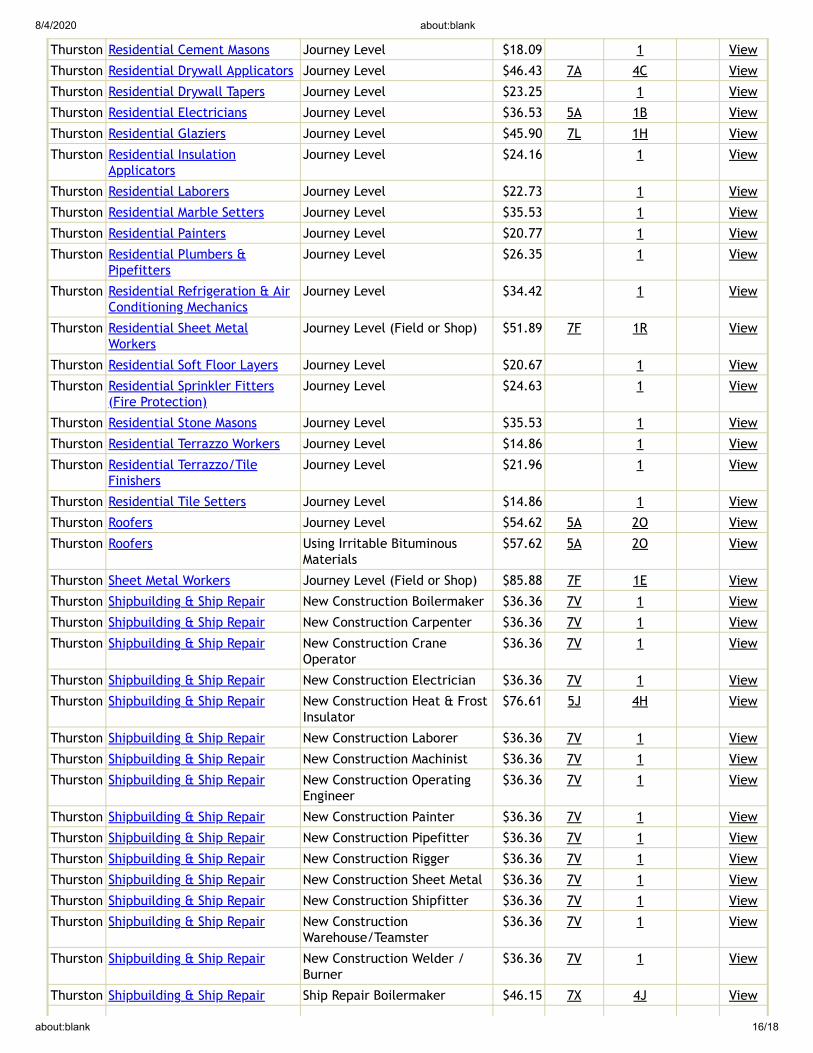
8/4/2020 about:blank
about:blank 16/18
Thurston Residential Cement Masons Journey Level $18.09 1 View
Thurston Residential Drywall Applicators Journey Level $46.43 7A 4C View
Thurston Residential Drywall Tapers Journey Level $23.25 1 View
Thurston Residential Electricians Journey Level $36.53 5A 1B View
Thurston Residential Glaziers Journey Level $45.90 7L 1H View
Thurston Residential InsulationApplicators
Journey Level $24.16 1 View
Thurston Residential Laborers Journey Level $22.73 1 View
Thurston Residential Marble Setters Journey Level $35.53 1 View
Thurston Residential Painters Journey Level $20.77 1 View
Thurston Residential Plumbers &Pipefitters
Journey Level $26.35 1 View
Thurston Residential Refrigeration & AirConditioning Mechanics
Journey Level $34.42 1 View
Thurston Residential Sheet MetalWorkers
Journey Level (Field or Shop) $51.89 7F 1R View
Thurston Residential Soft Floor Layers Journey Level $20.67 1 View
Thurston Residential Sprinkler Fitters(Fire Protection)
Journey Level $24.63 1 View
Thurston Residential Stone Masons Journey Level $35.53 1 View
Thurston Residential Terrazzo Workers Journey Level $14.86 1 View
Thurston Residential Terrazzo/TileFinishers
Journey Level $21.96 1 View
Thurston Residential Tile Setters Journey Level $14.86 1 View
Thurston Roofers Journey Level $54.62 5A 2O View
Thurston Roofers Using Irritable BituminousMaterials
$57.62 5A 2O View
Thurston Sheet Metal Workers Journey Level (Field or Shop) $85.88 7F 1E View
Thurston Shipbuilding & Ship Repair New Construction Boilermaker $36.36 7V 1 View
Thurston Shipbuilding & Ship Repair New Construction Carpenter $36.36 7V 1 View
Thurston Shipbuilding & Ship Repair New Construction CraneOperator
$36.36 7V 1 View
Thurston Shipbuilding & Ship Repair New Construction Electrician $36.36 7V 1 View
Thurston Shipbuilding & Ship Repair New Construction Heat & FrostInsulator
$76.61 5J 4H View
Thurston Shipbuilding & Ship Repair New Construction Laborer $36.36 7V 1 View
Thurston Shipbuilding & Ship Repair New Construction Machinist $36.36 7V 1 View
Thurston Shipbuilding & Ship Repair New Construction OperatingEngineer
$36.36 7V 1 View
Thurston Shipbuilding & Ship Repair New Construction Painter $36.36 7V 1 View
Thurston Shipbuilding & Ship Repair New Construction Pipefitter $36.36 7V 1 View
Thurston Shipbuilding & Ship Repair New Construction Rigger $36.36 7V 1 View
Thurston Shipbuilding & Ship Repair New Construction Sheet Metal $36.36 7V 1 View
Thurston Shipbuilding & Ship Repair New Construction Shipfitter $36.36 7V 1 View
Thurston Shipbuilding & Ship Repair New ConstructionWarehouse/Teamster
$36.36 7V 1 View
Thurston Shipbuilding & Ship Repair New Construction Welder /Burner
$36.36 7V 1 View
Thurston Shipbuilding & Ship Repair Ship Repair Boilermaker $46.15 7X 4J View

8/4/2020 about:blank
about:blank 17/18
Thurston Shipbuilding & Ship Repair Ship Repair Carpenter $44.95 7X 4J View
Thurston Shipbuilding & Ship Repair Ship Repair Crane Operator $45.06 7Y 4K View
Thurston Shipbuilding & Ship Repair Ship Repair Electrician $46.22 7X 4J View
Thurston Shipbuilding & Ship Repair Ship Repair Heat & FrostInsulator
$76.61 5J 4H View
Thurston Shipbuilding & Ship Repair Ship Repair Laborer $46.15 7X 4J View
Thurston Shipbuilding & Ship Repair Ship Repair Machinist $46.15 7X 4J View
Thurston Shipbuilding & Ship Repair Ship Repair Operating Engineer $45.06 7Y 4K View
Thurston Shipbuilding & Ship Repair Ship Repair Painter $46.15 7X 4J View
Thurston Shipbuilding & Ship Repair Ship Repair Pipefitter $46.15 7X 4J View
Thurston Shipbuilding & Ship Repair Ship Repair Rigger $46.15 7X 4J View
Thurston Shipbuilding & Ship Repair Ship Repair Sheet Metal $46.15 7X 4J View
Thurston Shipbuilding & Ship Repair Ship Repair Shipwright $44.95 7X 4J View
Thurston Shipbuilding & Ship Repair Ship Repair Warehouse /Teamster
$45.06 7Y 4K View
Thurston Sign Makers & Installers(Electrical)
Journey Level $18.04 1 View
Thurston Sign Makers & Installers (Non-Electrical)
Journey Level $15.50 1 View
Thurston Soft Floor Layers Journey Level $51.07 5A 3J View
Thurston Solar Controls For Windows Journey Level $13.50 1 View
Thurston Sprinkler Fitters (FireProtection)
Journey Level $82.39 5C 1X View
Thurston Stage Rigging Mechanics (NonStructural)
Journey Level $13.50 1 View
Thurston Stone Masons Journey Level $58.82 5A 1M View
Thurston Street And Parking Lot SweeperWorkers
Journey Level $16.00 1 View
Thurston Surveyors Chain Person $65.11 7A 3K View
Thurston Surveyors Instrument Person $65.71 7A 3K View
Thurston Surveyors Party Chief $66.81 7A 3K View
Thurston Telecommunication Technicians Journey Level $44.70 6Z 1B View
Thurston Telephone Line Construction -Outside
Cable Splicer $41.81 5A 2B View
Thurston Telephone Line Construction -Outside
Hole Digger/Ground Person $23.53 5A 2B View
Thurston Telephone Line Construction -Outside
Installer (Repairer) $40.09 5A 2B View
Thurston Telephone Line Construction -Outside
Special Aparatus Installer I $41.81 5A 2B View
Thurston Telephone Line Construction -Outside
Special Apparatus Installer II $40.99 5A 2B View
Thurston Telephone Line Construction -Outside
Telephone Equipment Operator(Heavy)
$41.81 5A 2B View
Thurston Telephone Line Construction -Outside
Telephone Equipment Operator(Light)
$38.92 5A 2B View
Thurston Telephone Line Construction -Outside
Telephone Lineperson $38.92 5A 2B View
Thurston Telephone Line Construction -Outside
Television Groundperson $22.32 5A 2B View

8/4/2020 about:blank
about:blank 18/18
Thurston Telephone Line Construction -Outside
Television Lineperson/Installer $29.60 5A 2B View
Thurston Telephone Line Construction -Outside
Television System Technician $35.20 5A 2B View
Thurston Telephone Line Construction -Outside
Television Technician $31.67 5A 2B View
Thurston Telephone Line Construction -Outside
Tree Trimmer $38.92 5A 2B View
Thurston Terrazzo Workers Journey Level $54.06 5A 1M View
Thurston Tile Setters Journey Level $54.06 5A 1M View
Thurston Tile, Marble & TerrazzoFinishers
Finisher $44.89 5A 1B View
Thurston Traffic Control Stripers Journey Level $47.68 7A 1K View
Thurston Truck Drivers Asphalt Mix Over 16 Yards $60.84 5D 4Y 8L View
Thurston Truck Drivers Asphalt Mix To 16 Yards $60.00 5D 4Y 8L View
Thurston Truck Drivers Dump Truck $60.00 5D 4Y 8L View
Thurston Truck Drivers Dump Truck & Trailer $60.84 5D 4Y 8L View
Thurston Truck Drivers Other Trucks $60.84 5D 4Y 8L View
Thurston Truck Drivers - Ready Mix Transit Mix $60.84 5D 4Y 8L View
Thurston Well Drillers & Irrigation PumpInstallers
Irrigation Pump Installer $17.53 1 View
Thurston Well Drillers & Irrigation PumpInstallers
Oiler $13.50 1 View
Thurston Well Drillers & Irrigation PumpInstallers
Well Driller $18.00 1 View