rtn commissioning
DESCRIPTION
RTNTRANSCRIPT

Prepared By Muhammad Farooq
Optix RTN 900 Series Configuration Guide
U2000 Web LCT V100R008

2
This Document Will Guide each and every step of Configuration RTN series using Web LCT U2000
How to Configure a new Link How to Configure ETH services How to Configure TDM ServicesHow to cascade Two RTNs How to make visible RTN on NMS
Prepared By Muhammad Farooq

3
How To LOG IN RTN
1. Connect One End of a straight Cable with Laptop LAN port
and other end with NMS/EXT port of RTN on CSHO card
Prepared By Muhammad Farooq
NMS / EXT Port

4
2. Assign IP to Laptop : 129.9.9.9 and subnet Mask : 255.255.0.0
Prepared By Muhammad Farooq

5
1. Make sure your Laptop is connected with RTN and connection is established 2. Open Web LCT software . Starting black window will open and then LOGIN page will open User Name : adminPassword : “Huawei@123” (For the very first time enter the password “Changeme_123” and then click login
Prepared By Muhammad Farooq
Huawei@123Enter the code
User Name :admin

6
3. Go to NE search and click advance search Search NE window will open
Prepared By Muhammad Farooq
Click on advance search

7
4. Make sure you are searching NE in the same domain that you assign to your LaptopThen click search NE
Prepared By Muhammad Farooq
Domain Must be same

8
IF RTN is connected with NMS then It will Search Many Non GNE NEs . Click on GNE and the click on ADD NE . NE will be added to main page
Prepared By Muhammad Farooq

9Prepared By Muhammad Farooq
To Login NE

10
5. Select the added NE and click on NE Login Then NE Login Window Will Open User Name : “lct” Password : “password”
Prepared By Muhammad Farooq

11
6. Click on NE Explorer after Login . NE Explorer Window will open . This is the Slot Layout of RTN
Prepared By Muhammad Farooq

12
When you are configuring a new RTN first you have to Add all physical boards that you are inserted in IDU . All newly inserted board will show in Light green color . Click on Add Physical Board .Color of newly inserted boards will change into Dark green color which shows that installed boards are running properly . Do switch on the ODU radio . ODU will appear in on the top against each ISV3 card respectively . Add the ODU
Prepared By Muhammad Farooq

13
Before starting the configuration make sure that all boards are running properly that is all boards must be in green color
Prepared By Muhammad Farooq

14
7. Go to Configration MW Link Configration . Configration Window will open select the card which you need to configure
Prepared By Muhammad Farooq

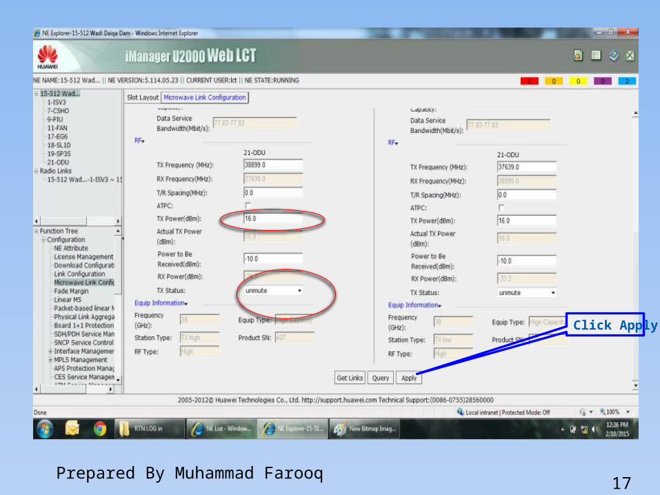
15
Configuration window will open . Here you need to enter B/m values •Protection (1+0 /1+1/XPIC ) According to plan given by client• IF Channel (given in the row of Radio Model of Link Budget ( 38G_XMC2_128Q_28M_161M ) here 28 Mhz are the channel spacing •Modulation Mode (38G_XMC2_128Q_28M_161M ) Here 128 QAM 161MBPS are the modulation Mode •TX frequency ( Given in the row of TX Channels of LB )•TX power ( Given in the TX power dbm Row of LB )•Put the TX status to unmute
Prepared By Muhammad Farooq

16Prepared By Muhammad Farooq
17Prepared By Muhammad Farooq
Click Apply

18
8. Go to configuration NE attribute and modify the b/m parameters
•NE Name i.e. NE 15-512 Wadi Daqa Dam •NE ID 512 •Extended ID 15
Prepared By Muhammad Farooq

19
Now your Link is configured you can start the Alignment Note :Before starting the Alignment you must check the interference . First turn off the ODU of Near End and check RSL of Farend if RSL is at -90 dbm then there is no interference . Repeat the same procedure at the farend to check the interference at both ends
Prepared By Muhammad Farooq

20
9. Go to NE time localization and set the time zone (UTC + 4 : 00 ) – Asia / Muscat
Prepared By Muhammad Farooq

21
10 . Go to NE Time Synchronization and put the Synchronous mode to NM and then synchronized with NM Time
Prepared By Muhammad Farooq
Click here

22
11 . Go to NE Performance and enable 15 minutes and 24 hours performance
Prepared By Muhammad Farooq
Check this Box Check this Box
Apply

23
12 . If you need to connect RTN with ATN Node then Go to communication Communication Parameters . A new Window will open and enter the b/m values
•IP (Provided by customer )• Subnet Mask (Provided by customer )•Gateway (Provided by customer )
Prepared By Muhammad Farooq

24
For Physically connectivity RTN to ATN connect one end of the straight cable to the RTN port GE 1 , GE 2 …. And connect the other end to the ATN port as instructed by IP personnel Normally FE0 FE1 … ports are used Note : Before connecting make sure that ATN ports are enabled you may ping the IP of ATN to check the port status
Prepared By Muhammad Farooq

25
Configuring LAG (Link Aggregation group )
Link aggregation allows multiple links that are attached to the same equipment to be aggregated to form a link aggregation group (LAG) so that the bandwidths and availability of the links increase.
Prepared By Muhammad Farooq

26
RTN 950 A Ports / Slots
GE 1 GE2 GE3 GE4 are used for 3 G GE 5 and GE 6 are used for 4 G
If you need to configure 1+1 Link you will use the slot pairs 1-2 3-54-6Prepared By Muhammad Farooq

27
Scenario 1:There are 2+0 XPIC links. V-1 & H-1 form one XPIC group one XPIC group on frequency spot-
1 & V-2 & H-2 form another XPIC group on frequency spot-2.
Scenario 2:There are both 1+0 and 1+0 XPIC links.
Prepared By Muhammad Farooq
Scenario 3:There is 1+0 link & 1 XPIC SD link. V-M is vertical main & V-D is vertical diversity & H-M is Horizontal Main & H-D is Horizontal Diversity.

28Prepared By Muhammad Farooq
Scenario 4 :There is 1+0 link & 1 XPIC SD link. V-M is vertical main & V-D is vertical diversity & H-M is Horizontal Main & H-D is Horizontal Diversity.
Scenario 5:There is 1+0 XPIC & 1 XPIC SD Link.
Scenario 6:There only 1+1 XPIC-SD links.

29
Configuring ETH & TDM Services
13 – Configuring ETH Services
Go to Interface Management Ethernet Interface . A new window will open showing ports configuration
Note : For 3 G Set 17 EG6 1 port to “100 M full Duplex” working Mode For 4 G set the port on 1000 M full Duplex working Mode
Prepared By Muhammad Farooq

30
Enabled the Port Encapsulation Type must be 802.1Q Working Mode Must be 100 M Full duplex
Prepared By Muhammad Farooq

31
Go To Ethernet Service Management E LAN Service
Prepared By Muhammad Farooq

32
For New services click New .A new window will open and put the service Name . Then click on Get UNI Port
Prepared By Muhammad Farooq

33
A New will open showing Available ports and selected ports . First Select the board i.e. 17 EG6 Now in selection Window do select the available free port on which you connect the cable of Node B 17 EG 6 -1 (Port 1 )……17 EG 6- 6 (port 6)put the LAN ID against selected port as per plan Now do select the IF board to Synchronize EG 6- 1 with ISV3 Ports . Also put the LAN ID as per plan and click ok . Configured ports will visible in the below window .
Prepared By Muhammad Farooq

34Prepared By Muhammad Farooq

35Prepared By Muhammad Farooq
Selected Ports will visible there along with configuration

36
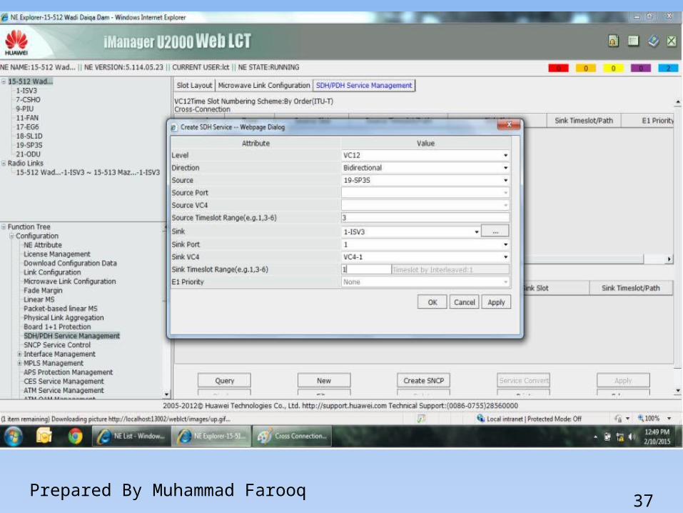
14 – Configuring TDM Services .
Go to Configuration SDH / PDH service management and click on new . A new window will open . Select the source card . And
available time slot . Select Sink card and sink time slot
and do apply
Prepared By Muhammad Farooq
37Prepared By Muhammad Farooq

38
14 - If you Need to connect New RTN with Existing RTN then fallow below steps
For NMS visibility Connect NMS port of Existing RTN with EXT port
of New RTN through a straight cable . After connecting this all sites must be visible when you login the
New RTNConnect available GE 1 port of
Existing RTN with GE1 port of New RTN .
Prepared By Muhammad Farooq