rtc-8070 - crane rental company · rtc– 8070 upper structure boom patented design boom side...
TRANSCRIPT

TELESCOPIC ROUGHTERRAIN CRANE70-Ton (63.50 mt)
• 70-ton at a 9-foot radius• 101,400 lbs. gross vehicle weight
(fully loaded)• 127-foot, full power, four-section
boom with quick reeve boom head• 67-foot, two-stage, offsettable
swing-away attachment• Fly offsets of 2, 20 and 40 degrees• No deducts in capacity for stowed
attachment• New graphic screen MG-434 rated
capacity limiter• Off-highway 210 HP Cummins engine• Composite operator’s cab• Pilot-operated hydraulic controls• Pre-painted
RTC-8070

Litho in USA 8/01 #5337 (Supersedes #5330)
SpecificationsTelescopic Boom Rough Terrain Crane
RTC–8070 70–ton (63.50 metric tons)
FE
Tailswing of Counterweight 13’ 9.25” 4.20
Turning radius (4–wheel steer 23’ 10” 7.26
centerline of tires)
Turning radius (2–wheel steer 46’ 10” 14.28
centerline of tires)
Turning radius (4–wheel steer outside 27’ 5” 8.36
front carrier corner)
Turning radius (2–wheel steer outside 49’ 10” 15.19
front carrier corner)
C of RotationL
General Dimensions feet meters
LC of Rotation
45’ 7”(13.90 m)
41’ 0”(12.50 m)
7’ 0”(2.13 m)
23.8�
10.9�
20.2�
9.4�6’ 9.5”
(2.07 m)
11’ 9”(3.58 m)
5’ 9.5”(1.77 m)
11’ 6”(3.51 m)
27’ 4.25”(8.33 m)
4’ 10”(1.47 m)
10’ 0.75” (3.07 m)
8’ 2.5” (2.50 m)Centerline of tires
12’ 0.75” (3.68 m)
16’ 4.75” (5.00 m)18’ 4.75” (5.61 m)
23’ 0” (7.01 m)25’ 0” (7.62 m)
��������
Link–Belt
Tire Size
Dimension 29.5 x 25 29.5 R 25
A 12’ 10.75” (3.93 m) 12’ 11.75” (3.97 m)B 7’ 11.5” (2.42 m) 8’ 0.5” (2.44 m)C 2’ 8” (0.81 m) 2’ 9” (0.84 m)D 12’ 5” (3.78 m) 12’ 6” (3.83 m)E 9” (0.23 m) 10” (0.25 m)F 14.25” (0.36 m) 15.25” (0.39 m)G 11.25” (0.29 m) 12.25” (0.31 m)
10’ 10.5”(3.31 m)
A
B
C C
D
9’ 5.5”(2.88 m)
3’ 9”(1.14 m)
3’ 3”(0.99 m)
7.25”(0.18 m)
G
Full Retraction
Full Extension
Intermediate Retraction

���RTC–8070
Upper Structure� BoomPatented Design� Boom side plates have diamond shaped
impressions for superior strength to weightratio and 100,000 p.s.i. (689.5 MPa) steelangle chords for lateral stiffness.
� Boom telescope sections are supported bytop, bottom and adjustable side wearshoes to prevent metal to metal contact.
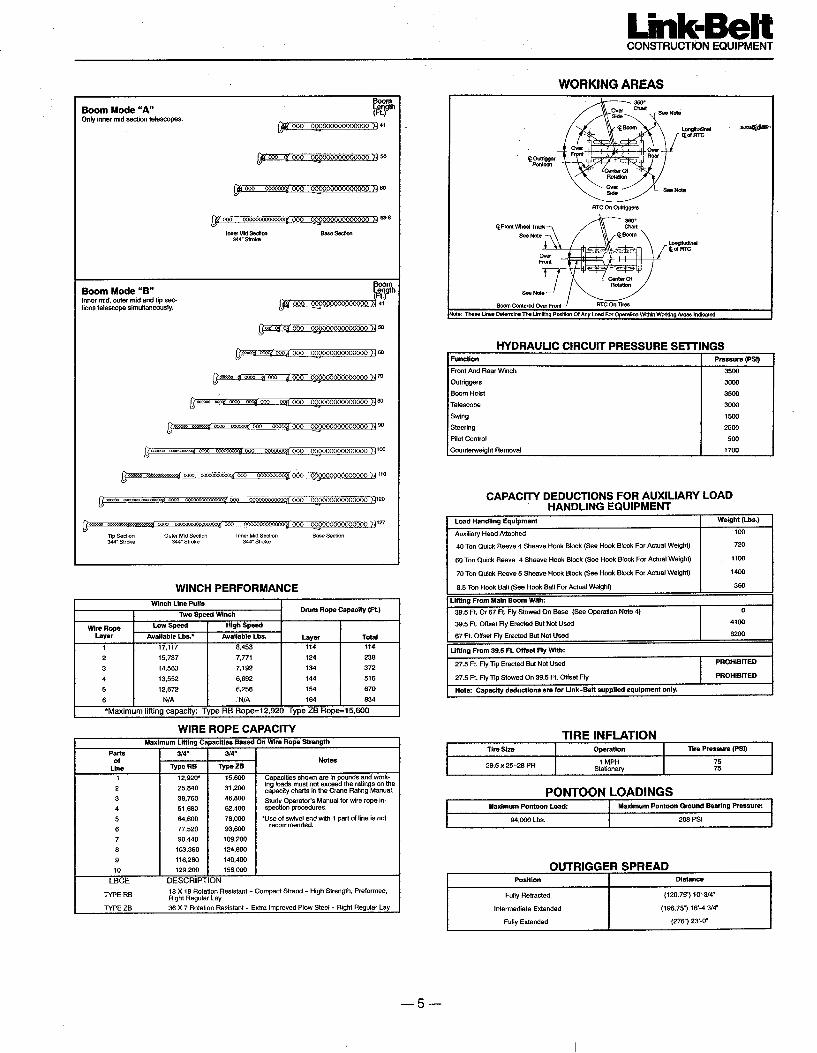
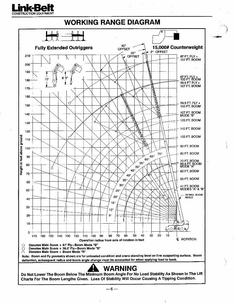
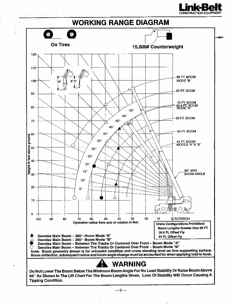
Standard Boom� 41’ – 127’ (12.50 – 38.71 m) four–section
full power boom.� Basic mode (or mode ’B’) is the full pow-
er, synchronized mode of telescoping allsections proportionally to 127’ (38.71 m).
� The exclusive A–max mode (or mode‘A’) extends only the inner mid–sectionto 69.5’ (21.21 m) offering increased ca-pacities for in–close, maximum capacitypicks.
� Mechanical Boom Angle IndicatorBoom Head� Five 16.5” (0.42 m) root diameter steel nylon
sheaves handle up to ten parts of wire rope.� Quick reeve design� Boom head designed for quick reeve of
hook block� Rope dead end lugs provided on each side
of boom head� Easily removable wire rope guards� Fly pinning alignment tool
Boom Elevation� Hydraulic cylinder with holding valves and
bushing in each end.� Hand control for controlling boom
elevation from –3 to +78�.Optional Auxiliary Lifting Sheave� Single 16.5” (0.42 m) root diameter steel
sheave with removable wire rope guardmounted on boom.
� Use with one or two parts of line off theoptional front winch.
� Does not affect erection of fly or use ofmain head sheaves for multiple reeving.
Optional� 70–ton (63.5 mt) 5–sheave, quick reeve
hook block� 60–ton (54.43 mt) 4–sheave, quick reeve
hook block� 40–ton (36.28 mt) 4–sheave, quick reeve
hook block� 8.5–ton (7.7 mt) hook ball� Boom floodlight� Fly pinning alignment tool
� FlyOptional� 39.5’ (12.04 m) offsettable stowable one–
piece lattice type with lugs to allow forsecond section. Can be offset 2�, 20� or40�
� 39.5’ – 67’ (12.04 – 20.42 m) offsettablestowable two–piece lattice type. Can beoffset 2�, 20� or 40�
� Cab and ControlsEnvironmental Cab� ������������ ������ ���������� ��
������������ ��������������� ����� Isolated from sound and vibration by a
neoprene seal� Six–way adjustable operator’s seat with
retractable seat belt� Four–way adjustable tilting and locking
steering wheel.� All windows are tinted and tempered
safety glass.� Slide by door opens to 3’ (0.91 m) width.� Sliding rear and right side windows and
swing up roof windows for maximum visibility and ventilation.
� Outrigger controls and sight level bubblealso provided in upper cab.
� Audible swing alarm. � Warning horn� Backup alarm � Travel lights� Cab mounted work lights � Sun screen� Electric windshield wiper � Mirrors� Top hatch window wiper � Cup holder� Fire extinguisher � Circulating fan� Dome light � Defroster fan
Optional� Amber strobe light and rotating beacon.� Emergency steering system� Hydraulic or diesel heater� Air conditioning
ControlsHydraulic controls (joystick type) for:� Main winch � Boom hoist� Drum rotation indicators � Swing� Optional auxiliary winch.� Optional single–axis controls.
Foot controls for:� Boom telescope� Swing brake� Engine throttle with throttle lock
Cab InstrumentationCorner post mounted gauges for:� Hydraulic oil temperature� Convertor temperature� Audio/Visual warning system� Water temperature � Air pressure� Tachometer � Voltmeter� Oil pressure � Fuel
� Rated Capacity Limiter� Microguard 434 Graphic audio–visual
warning system built into dash with anti–two block and function limiters.
Operating data available includes:� Machine configuration.� Boom length � Boom angle� Head height � Radius of load� Allowed load � Actual load� % of allowed load
Presettable alarms include:� Maximum and minimum boom angles.� Maximum tip height.� Maximum boom length.� Swing left/right positions.� Operator defined area alarm is standard.� Anti–two block weight designed for quick
reeve of hookblock.
Optional� Internal RCL light bar: Visually informs
operator when crane is approaching maxi-mum load capacity with a series of threelights; green, yellow and red.
� External RCL light bar: Visually informsground crew when crane is approachingmaximum load capacity kickouts and pre-settable alarms with a series of threelights; green, yellow and red.
� Swing� Bi–directional hydraulic swing motor
mounted to a planetary reducer for 360�continuous smooth swing at 2 r.p.m.
� Swing park brake – 360� electric overhydraulic (spring applied, hydraulic re-leased) multi–disc brake mounted on thespeed reducer. Operated by toggle switchin overhead control console.
� Swing brake – 360�, foot operated, hy-draulic applied disc brake mounted on thespeed reducer.
� Travel swing lock – Standard; two posi-tion travel lock (pin device) operated fromthe operator’s cab.
� Counterweight – Bolted to upper struc-ture frame. 15,000 lbs. (6 804 kg). Hydraulically controlled counterweight removal optional.
Optional� 360� swing lock (meets New York City
requirements).
� Hydraulic SystemMain Pump� Four–section gear–type pump.� Combined pump capacity 136 gpm (515
lpm)� Mounted on torque converter, powered by
engine through a pump disconnect.� Pump disconnect is a spline type clutch
engaged/disengaged from carrier.� Pump operates at 3,500 p.s.i. (24.1 MPa)
maximum system pressure.� O–Ring Face Seal (ORFS) technology
throughout with hydraulic oil cooler.Pilot Pressure/Counterweight Removal� Pressure compensated piston pump pow-
ered by carrier engine. Operates at 1,500psi (10.3 MPa) maximum.
Telescope/Outrigger/Steering Pump� Single gear–type pump, 25 gpm (95 lpm)
maximum. Mounted on torque converter,powered by engine through a direct me-chanical drive.
� Pump operates at 3,000 p.s.i. (20.7 MPa)maximum system pressure.
Reservoir� 170 gal. (643.5 L) capacity. Diffuser for
deaeration.Filtration� One, 10–micron filter located inside hy-
draulic reservoir. Accessible for easy re-placement.
Control Valves:� Six separate pilot operated control valves
allow simultaneous operation of all cranefunctions.
RTC–8070–3–
Optional� Pump disconnect
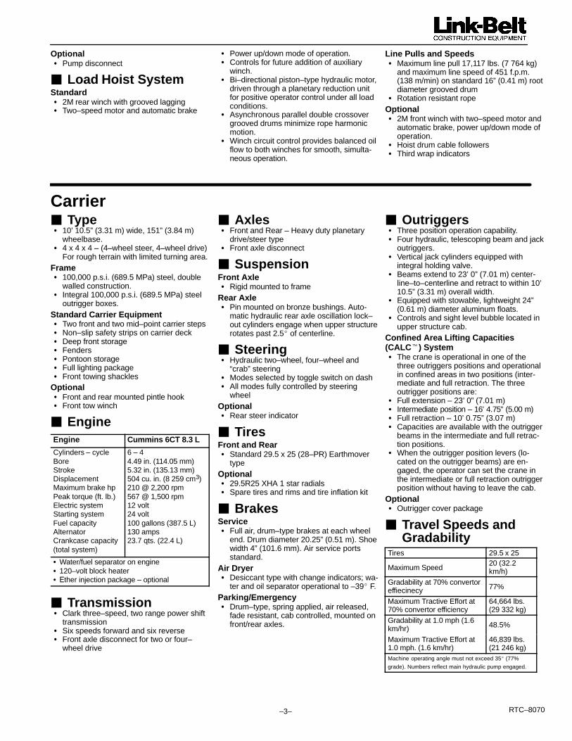
� Load Hoist SystemStandard� 2M rear winch with grooved lagging� Two–speed motor and automatic brake
� Power up/down mode of operation.� Controls for future addition of auxiliary
winch.� Bi–directional piston–type hydraulic motor,
driven through a planetary reduction unitfor positive operator control under all loadconditions.
� Asynchronous parallel double crossovergrooved drums minimize rope harmonic motion.
� Winch circuit control provides balanced oilflow to both winches for smooth, simulta-neous operation.
Line Pulls and Speeds� Maximum line pull 17,117 lbs. (7 764 kg)
and maximum line speed of 451 f.p.m.(138 m/min) on standard 16” (0.41 m) rootdiameter grooved drum
� Rotation resistant ropeOptional� 2M front winch with two–speed motor and
automatic brake, power up/down mode of operation.
� Hoist drum cable followers� Third wrap indicators
Carrier� Type� 10’ 10.5” (3.31 m) wide, 151” (3.84 m)
wheelbase.� 4 x 4 x 4 – (4–wheel steer, 4–wheel drive)
For rough terrain with limited turning area.Frame� 100,000 p.s.i. (689.5 MPa) steel, double
walled construction.� Integral 100,000 p.s.i. (689.5 MPa) steel
outrigger boxes.Standard Carrier Equipment� Two front and two mid–point carrier steps� Non–slip safety strips on carrier deck� Deep front storage� Fenders� Pontoon storage� Full lighting package� Front towing shackles
Optional� Front and rear mounted pintle hook� Front tow winch
� EngineEngine Cummins 6CT 8.3 L
Cylinders – cycleBoreStrokeDisplacementMaximum brake hpPeak torque (ft. lb.)Electric systemStarting systemFuel capacityAlternatorCrankcase capacity(total system)
6 – 44.49 in. (114.05 mm)5.32 in. (135.13 mm)504 cu. in. (8 259 cm3)210 @ 2,200 rpm567 @ 1,500 rpm12 volt24 volt100 gallons (387.5 L)130 amps23.7 qts. (22.4 L)
� Water/fuel separator on engine� 120–volt block heater� �ther injection package – optional
� Transmission� Clark three–speed, two range power shift
transmission� Six speeds forward and six reverse� Front axle disconnect for two or four–
wheel drive
� Axles� Front and Rear – Heavy duty planetary
drive/steer type� Front axle disconnect
� SuspensionFront Axle� Rigid mounted to frame
Rear Axle� Pin mounted on bronze bushings. Auto-
matic hydraulic rear axle oscillation lock–out cylinders engage when upper structurerotates past 2.5� of centerline.
� Steering� Hydraulic two–wheel, four–wheel and
“crab” steering� Modes selected by toggle switch on dash� All modes fully controlled by steering
wheelOptional� Rear steer indicator
� TiresFront and Rear� Standard 29.5 x 25 (28–PR) Earthmover
typeOptional� 29.5R25 XHA 1 star radials� Spare tires and rims and tire inflation kit
� BrakesService� Full air, drum–type brakes at each wheel
end. Drum diameter 20.25” (0.51 m). Shoewidth 4” (101.6 mm). Air service portsstandard.
Air Dryer� Desiccant type with change indicators; wa-
ter and oil separator operational to –39� F.Parking/Emergency� Drum–type, spring applied, air released,
fade resistant, cab controlled, mounted onfront/rear axles.
� Outriggers� Three position operation capability.� Four hydraulic, telescoping beam and jack
outriggers.� Vertical jack cylinders equipped with
integral holding valve.� Beams extend to 23’ 0” (7.01 m) center-
line–to–centerline and retract to within 10’10.5” (3.31 m) overall width.
� Equipped with stowable, lightweight 24”(0.61 m) diameter aluminum floats.
� Controls and sight level bubble located inupper structure cab.
Confined Area Lifting Capacities(CALC�) System� The crane is operational in one of the
three outriggers positions and operationalin confined areas in two positions (inter-mediate and full retraction. The three outrigger positions are:
� Full extension – 23’ 0” (7.01 m)� Intermediate position – 16’ 4.75” (5.00 m)� Full retraction – 10’ 0.75” (3.07 m)� Capacities are available with the outrigger
beams in the intermediate and full retrac-tion positions.
� When the outrigger position levers (lo-cated on the outrigger beams) are en-gaged, the operator can set the crane inthe intermediate or full retraction outriggerposition without having to leave the cab.
Optional� Outrigger cover package
� Travel Speeds and Gradability
Tires 29.5 x 25
Maximum Speed20 (32.2km/h)
Gradability at 70% convertoreffiecinecy 77%
Maximum Tractive Effort at70% convertor efficiency
64,664 lbs. (29 332 kg)
Gradability at 1.0 mph (1.6km/hr) 48.5%
Maximum Tractive Effort at1.0 mph. (1.6 km/hr)
46,839 lbs. (21 246 kg)
Machine operating angle must not exceed 35� (77%
grade). Numbers reflect main hydraulic pump engaged.

���RTC–8070
� Axle LoadsBase machine with standard 41’ to127’ (12.50 – 38.71 m) four–section �
Upper facing front Upper facing rear127’ (12.50 – 38.71 m) four–sectionboom, 2M main winch with 2–speedhoisting and power up/down, 670’
G.V.W.�Front axle Rear axle Front axle Rear axlehoisting and power up/down, 670’
(204 m) 3/4” (19 mm) wire rope. 4x4x4carrier with Cummins 6CT 8.3L en- lbs. kg. lbs. kg. lbs. kg. lbs. kg. lbs. kg.carrier with Cummins 6CT 8.3L en-gine, 29.5 x 25 tires, counterweightand no fuel. 93,842 42 566 43,524 19 742 50,318 22 824 39,721 18 017 54,121 24 549
Remove 29.5 x 25 tires and wheels –6,732 –3 054 –3,366 –1 527 –3,366 –1 527 –3,366 –1 527 –3,366 –1 527
29.5R25 XHA Tires 964 438 482 219 482 219 482 219 482 219
Remove outrigger beams –5,235 –2 374 –2,461 –1 116 –2,774 –1 258 –2,461 –1 116 –2,774 –1 258
Jack cylinder beams 154 70 72 33 82 27 72 33 82 37
Tow winch 686 311 1,002 454 –316 –143 1,002 454 –316 –143
100 gallons (378.5 L) fuel 685 310 364 165 321 145 364 165 321 145
2M auxiliary winch with 670’ (204 m)of 3/4” (19 mm) rope 823 373 –219 –99 1,043 473 977 443 –154 –70
Remove front carrier counterweights –1,000 –454 –1,306 –592 306 139 –1,306 –592 306 139
Hydraulic counterweight removal 353 160 163 74 190 86 518 235 –165 –75
Remove counterweight –15,000 –6 804 8,223 3 734 –23,233 –10 538 –22,041 –9 998 7,041 3 194
Diesel heater with tank 70 32 19 9 51 23 45 21 25 11
Hydraulic heater 170 77 47 21 123 56 110 50 60 27
Air conditioning 287 130 55 25 232 105 209 95 78 35
39.5’ (12.04 m) offsettable lattice flystowed 1,602 727 2,780 1 261 –1,178 –534 –1,305 –592 2,907 1 319
39.5’ – 67’ (12.04 – 20.42 m) offset-table lattice fly stowed 2,380 1 080 3,649 1 655 –1,269 –576 –1,458 –661 3,838 1 741
Fly storage brackets with all fly op-tions 160 73 268 122 –108 –49 –120 –54 280 127
Auxiliary lifting sheave assembly 110 50 361 164 –251 –114 –260 –118 370 168
8.5–ton (7.71 mt) hook ball @ frontbumper 360 163 566 256 –206 –93 n/a n/a n/a n/a
70–ton (63.50 mt) 5–sheave hookblock @ front bumper 1,390 631 2,186 992 –796 –361 n/a n/a n/a n/a
60–ton (54.43 mt) 4–sheave hookblock @ front bumper 1,150 522 1,809 821 –659 –299 n/a n/a n/a n/a
� – Adjust gross weight and axle loading according to component weight. Note: All weights are � 3%.
Tire Max. Axle Load @ 20 mph (32.7 km/hr)
29.5 x 25 (28–PR)
29.5R25 XHA 1 Star
53,000 (24 041 kg)
53,000 (24 041 kg)
Link–Belt Construction Equipment Company Lexington, Kentucky www.linkbelt.com�Link–Belt is a registered trademark. Copyright 2001. All rights reserved. We are constantly improving our products and therefore reserve the right to change designs and specifications.

ALL THE TRADITIONALLINK-BELT STANDARDS:PRECISION, COMFORT,RELIABILITY,CONTROLLABILITY,PLUS INDUSTRY-FIRSTTECHNOLOGY ANDINNOVATIONS
Base Rating• 70-ton nominal rating
Boom• 41 to 127 feet, full power, four-section• Quick reeve boom head• Maximum tip of 202 feet
Attachments• 39.5-foot, one-stage swing-away fly with
2, 20 and 40 degree offsets (new)• 39.5 to 67 feet, two-stage swing-away fly
with 2, 20 and 40 degree offsets (new)No deducts in capacity for stowedattachments (new)
Counterweight• 15,000 lbs. that is removable from
superstructure• Counterweight removal system (optional)
WinchGrooved Drums:• 670 feet of rope storage capacity• 670 feet of 3/4 inch rope• 12,920 lbs. of permissible line pull• 451 FPM of maximum single line speed
Rated Capacity LimiterMicroguard 434 System:• Pictographic display• Presettable alarms• Operator defined area alarms
Powertrain• 210 HP Cummins 6BT 8.3 liter engine• Clark 6-speed forward and 6-speed
reverse powershift transmission• 4-wheel and 2-wheel drive
Suspension• Solid mounted on front axle• Oscillating cradle on rear axle
Steering3-Modes:• 2-wheel on front axle• 4-wheel on both axles• Crab on both axles
KEY FEATURES
Tires• 29.5x25 28 ply rating (standard)• 29.5R25 XHA (optional)
CALCConfined Area Lifting Capabilities
Pre-Paint• All components are pre-painted prior
to assembly
Miscellaneous StandardEquipment• Provisions for future winch installation• Type “RB” wire rope• Composite operator’s cab• Pilot-operated dual axis controllers• Hand-held outrigger controls (new)• Six points of access to the carrier deck• Full light package
Miscellaneous OptionalEquipment• Auxiliary lifting sheave• Front winch package• Winch rollers• Pilot-operated single axis controllers• Internal RCL load rating bar graph• External RCL load rating light bar (new)• Quick reeve hook blocks• Hook ball
Link-Belt Construction Equipment CompanyLexington, Kentucky® Link-Belt is a registered trademark. Copyright 1999. We are constantlyimproving our products and therefore reserve the right to change designsand specifications. Litho in U.S.A. 2/99 #4227
Service Continues After The SaleWhen you have invested in a Link-Belt crane, youhave also invested in a 125-year legacy of outstandingcustomer service and support. Link-Belt helps youmaintain your investment with the industry’s mostcomprehensive crane product support. Highlytrained parts and service department techniciansare committed to responding quickly to yourdowntime and get you going again … fast!
THE RTC-8070