rsi sg series - bensha rsi sg series...rsi sg series instruction manual 7.5 to 40hp - 230v ... - the...
TRANSCRIPT

2012 Benshaw Inc.©
890046-00-01
Sensorless Vector
Variable Frequency Drive
RSi SG Series
Instruction Manual
7.5 to 40HP - 230V
7.5 to 700HP - 460V
7.5 to 150HP - 600V
Benshaw retains the right to change specifications and illustrations in text without prior notification. The contents of this document maynot be copied without the explicit permission of Benshaw.
BENSHAWADVANCED CONTROLS & DRIVES

ii
TRADEMARK NOTICE
Benshaw and are registered trademarks of Benshaw Incorporated. Modbus is a registered trademark of Schneider Electric. UL is a trademark of Underwriters Laboratories, Incorporated.

iii
SAFETY INSTRUCTIONS
To prevent injury and property damage, follow these instructions during the installation and operation of the drive. Incorrect operation due to ignoring these instructions may cause harm or damage. The following symbols are used throughout the manual to highlight important information.
DANGER
WARNING
CAUTION
This symbol indicates the possibility of death or serious injury.
This symbol indicates the possibility of damage to the drive or other components.
This symbol indicates death or serious injury can occur if you do not follow instructions.
■ The meaning of each symbol in this manual and on your equipment is as
follows.
This is the safety alert symbol. Read and follow instructions carefully to avoid a dangerous situation.
This symbol alerts the user to the presence of “dangerous voltage” inside the product that might cause bodily harm or electric shock.
■ This manual should be placed in a location where it can be accessed by users.
■ This manual should be given to the person who actually uses the drive and is
responsible for its maintenance.

iv
WARNING Do not remove the cover while power is applied or the unit is in operation. Do not operate the drive with the front cover removed. Electric shock can occur due to
the exposed terminals and bus bars.
Do not remove the cover except for periodic inspections or wiring, even if the input power is not applied. The capacitor bank may remain charged for some time even when power is not applied.
Wiring and periodic inspections should be performed at least 10 minutes after
disconnecting the input power and after checking that the DC link voltage is discharged with a meter (below 30VDC).
CAUTION Install the drive on a non-flammable surface. Do not place flammable materials nearby.
Disconnect the input power if the drive has been damaged. Do not apply power to a
damaged drive or to a drive with parts missing. Do not connect a resistance directly between the DC Bus terminals (P1 (or P2)) and N.
Doing so can result in overheating and damaging the resistor.
After shutting down or disconnecting the drive, the drive may be hot to the touch. Verify that the power-up restart feature is off during servicing to prevent any
unexpected operation. Do not allow lint, paper, wood chips, dust, metallic chips or other foreign material into
the drive.
v
OPERATING PRECAUTIONS
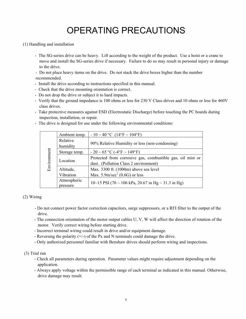
(1) Handling and installation
- The SG-series drive can be heavy. Lift according to the weight of the product. Use a hoist or a crane to move and install the SG-series drive if necessary. Failure to do so may result in personal injury or damage to the drive.
- Do not place heavy items on the drive. Do not stack the drive boxes higher than the number recommended. - Install the drive according to instructions specified in this manual. - Check that the drive mounting orientation is correct. - Do not drop the drive or subject it to hard impacts. - Verify that the ground impedance is 100 ohms or less for 230 V Class drives and 10 ohms or less for 460V
class drives. - Take protective measures against ESD (Electrostatic Discharge) before touching the PC boards during
inspection, installation, or repair. - The drive is designed for use under the following environmental conditions:
Env
iron
men
t
Ambient temp. - 10 ~ 40 C (14F ~ 104F) Relative humidity
90% Relative Humidity or less (non-condensing)
Storage temp. - 20 ~ 65 C (-4F ~ 149F)
Location Protected from corrosive gas, combustible gas, oil mist or dust. (Pollution Class 2 environment)
Altitude, Vibration
Max. 3300 ft. (1000m) above sea level Max. 5.9m/sec2 (0.6G) or less
Atmospheric pressure
10~15 PSI (70 ~ 106 kPa, 20.67 in Hg ~ 31.3 in Hg)
(2) Wiring
- Do not connect power factor correction capacitors, surge suppressors, or a RFI filter to the output of the
drive. - The connection orientation of the motor output cables U, V, W will affect the direction of rotation of the
motor. Verify correct wiring before starting drive. - Incorrect terminal wiring could result in drive and/or equipment damage. - Reversing the polarity (+/-) of the Px and N terminals could damage the drive. - Only authorized personnel familiar with Benshaw drives should perform wiring and inspections.
(3) Trial run - Check all parameters during operation. Parameter values might require adjustment depending on the
application. - Always apply voltage within the permissible range of each terminal as indicated in this manual. Otherwise,
drive damage may result.

vi
(4) Operation precautions
- When the Auto restart function is selected the drive will restart after a fault has occurred. - The Stop key on the keypad is always active regardless of drive control (start/stop) methods set in
parameters DRV-03 and DRV-91. - If Restart after Fault Reset (AFN-21) is set to “yes”, and a fault reset is made with the run command and/or
reference signal present, a sudden start will occur. Verify correct setting of this parameter and check that the run command and/or reference signal is turned off in advance of resetting any faults.
- Do not modify the drive. - Depending on the motor specifications and user ETH overload settings, the motor may not be protected by
electronic thermal function of drive. - The operation of the drive is intended to be controlled by either keypad command or control input signals.
Do not use a magnetic contactor or any other device that routinely disconnects the drive and reconnects the drive to the input supply power for the purpose of starting and stopping the motor.
- A noise filter may be installed to reduce the effect of electromagnetic interference. Consult factory for more information.
- In cases with input voltage unbalances, install an AC input reactor. - Power Factor capacitors and generators may become overheated and damaged due to harmonics created by
the drive. - Use an inverter duty rated motor or take measures to suppress the surge voltage at the motor with a dV/dT
filter or equivalent. A surge voltage attributable to wiring constant is generated at the motor terminals and may deteriorate mtoor insulation.
- The drive can be set to operate a motor at high-speeds. Verify the speed capability of motor and machinery prior to operating drive.
- Holding torque is not produced when using the DC-Brake function. Install separate equipment when holding torque is required.
(5) Fault prevention precautions
- If required, provide a safety backup such as an emergency mechanical brake to prevent any hazardous conditions if the drive fails during operation.
(6) Maintenance, inspection and parts replacement - Do not Meggar (hi-pot or insulation resistance) test the power or control circuits of the drive.
- Refer to Chapter 7 for periodic inspection and parts replacement details. (7) General instructions Many of the diagrams and drawings in this instruction manual may show the drive covers removed. Prior to operating the unit, be sure to restore covers and circuit protection according to specifications.

Table of Contents
vii
CHAPTER 1. BASIC INFORMATION 1-1
1.1 USING THIS MANUAL 1-1 1.2 GENERAL INFORMATION 1-1 1.3 CONTACTING BENSHAW/CURTISS WRIGHT FLOW CONTROL CO. 1-2 1.4 INSPECTION 1-3
1.4.1 Drive Model Number 1-3 1.4.2 Installation 1-3 1.4.3 Wiring 1-3
1.5 RECOMMENDED INSTALLATION 1-4
CHAPTER 2. DRIVE RATINGS AND SPECIFICATION 2-1
2.1 RATINGS 230V (7.5~40 HP) 2-1 2.2 RATINGS 460V (7.5~40 HP) 2-1 2.3 RATINGS 460V (50~125HP) 2-2 2.4 RATINGS 460V (150~700HP) 2-2 2.5 RATINGS 575V (7.5~40HP) 2-3 2.6 RATINGS 575V (50~125HP) 2-3 2.7 RATINGS 575V (150 ~ 400 HP) 2-4 2.8 GENERAL SPECIFICATION 2-5 2.9 DIMENSIONS 2-7
CHAPTER 3. INSTALLATION 3-1
3.1 INSTALLATION PRECAUTIONS 3-1 3.2 WIRING 3-3
3.2.1 Basic Wiring 3-3 3.2.2 Wiring Input and Output Power Terminals 3-9 3.2.3 Interference Suppression Measures 3-11 3.2.4 Terminal Layout 3-13 3.2.5 Wire Sizing and Terminal Lugs 3-14 3.2.6 Control Circuit Wiring 3-15 3.2.7 RS-485/Modbus-RTU Circuit Wiring 3-18 3.2.8 Keypad Wiring 3-19
CHAPTER 4. OPERATION 4-1
4.1 KEYPAD PROGRAMMING 4-1 4.1.1 LCD Keypad 4-1 4.1.2 Detailed Description 4-24-2 4.1.3 Parameter Setting and Adjustment 4-3 4.1.4 Parameter Groups 4-4 4.1.5 Easy Start Operation 4-6 4.1.6 Quickstart 1: Start / Stop and Speed Control via the Keypad 4-6 4.1.7 Quickstart 2: Two Wire Start and Control via Speed Potentiometer 4-7 4.1.8 Quickstart 3: Two Wire Start and Control via 4-20mA Analog Input 4-8

Table of Contents (continued)
viii
CHAPTER 5. PARAMETER LIST 5-1
5.1 DRV (DRIVE GROUP) PARAMETER LIST 5-1 5.2 FUN (FUNCTION GROUP) PARAMETER LIST 5-3 5.3 AFN (ADVANCED FUNCTION GROUP) PARAMETER LIST 5-6 5.4 I/O (INPUT/OUTPUT GROUP) PARAMETER LIST 5-10 5.5 APP (APPLICATION GROUP) PARAMETER LIST 5-16 5.6 EXT (4-20MA OUTPUT OPTION CARD) PARAMETER LIST 5-20
CHAPTER 6. PARAMETER DESCRIPTIONS 6-1
6.1 DRIVE GROUP [DRV] 6-1 6.2 FUNCTION GROUP [FUN] 6-9 6.3 ADVANCED FUNCTION GROUP [AFN] 6-25 6.4 INPUT/OUTPUT GROUP [I/O] 6-39 6.5 APPLICATION GROUP [APP] 6-61
CHAPTER 7. TROUBLE SHOOTING & MAINTENANCE 7-1
7.1 FAULT DISPLAY 7-1 7.2 FAULT REMEDY 7-3 7.3 TROUBLESHOOTING 7-6 7.4 HOW TO CHECK POWER COMPONENTS 7-7 7.5 MAINTENANCE 7-13
7.5.1 Precautions 7-13 7.5.2 Periodic Inspection Summary 7-13 7.5.3 Periodic Inspection 7-14 7.5.4 Parts Replacement 7-15
CHAPTER 8. OPTIONS 8-1
8.1 AVAILABLE OPTIONS 8-1 8.1.1 LCD Keypad 8-2 8.1.2 Remote Keypad Cable 8-2 8.1.3 4 – 20 mA Output Option Card 8-2 8.1.4 DeviceNet Communications Option Card 8-2 8.1.5 Profibus Communications Option Card 8-3 8.1.6 BACnet Communications Option Card 8-3 8.1.7 LonWorks Communications Option Card 8-3 8.1.8 Modbus TCP Option Card 8-3 8.1.9 Dynamic Braking Unit 8-3 8.1.10 Dynamic Braking Resistor(s) 8-6 8.1.11 NEMA TYPE 1 Conduit Box 8-6

Table of Contents (continued)
ix
CHAPTER 9. RS485/MODBUS-RTU COMMUNICATION 9-1
9.1 INTRODUCTION 9-1 9.1.1 Features 9-1 9.1.2 Connection Guide for Modbus-RTU Communication with PC, PLC and RS232/485 9-1 9.1.3 Before Installation 9-1
9.2 SPECIFICATION 9-2 9.2.1 Performance Specification 9-2 9.2.2 Hardware Specification 9-2 9.2.3 Communication Specification 9-2 9.2.4 Installation 9-2 9.2.5 Communication Parameters 9-3
9.3 OPERATION 9-3 9.3.1 Operating Steps 9-3
9.4 COMMUNICATION PROTOCOL (MODBUS-RTU) 9-4 9.5 PARAMETER CODE LIST 9-5
9.5.1 Common area address 0x0006 9-7 9.5.2 SG operating status in Address E, Common area 9-8
9.6 TROUBLESHOOTING 9-9
APPENDIX A- UL MARKING I
APPENDIX B- RELATED PARAMETERS III
APPENDIX C - DECLARATION OF CONFORMITY V


1-1
Chapter1. BasicInformation
1.1 UsingThisManual This manual is divided into 10 sections.
1) Basic Information 2) Drive Ratings and Specifications 3) Installation 4) Operation 5) Parameter Listing 6) Parameter Descriptions 7) Troubleshooting & Maintenance 8) Options 9) RS-485/Modbus-RTU Communications 10) Appendices
1.2 GeneralInformation
Benshaw offers its customers the following: Start-up services On-site training services Technical support Detailed documentation Replacement parts
NOTE: Information about products and services is available by contacting Benshaw. Refer to section 1.3, Contacting
Benshaw.
Start-Up Services
Benshaw technical field support personnel are available to do startup and conduct on-site training on the drive operations and
troubleshooting.
On-Site Training Services
Benshaw technical field support personnel are available to conduct on-site training on the operations and troubleshooting.
Technical Support
Benshaw technical support personnel are available (at no charge) to answer customer questions and provide technical support
over the telephone.
Documentation
Benshaw provides all customers with an RSi-SG Instruction Manual, Benshaw Publication #890046-00.
All RSi-SG drive documentation is available on-line at http://www.benshaw.cwfc.com.
Replacement Parts
Spare and replacement parts can be purchased from Benshaw. Contact Benshaw for more information.
Publication HistoryRefer to the Revision History located at the end of this manual.

Chapter 1 – Basic Information
1-2
1.3 ContactingBenshaw/CurtissWrightFlowControlCo.
Information about Benshaw products and services is available by contacting Benshaw at one of the following offices: Benshaw Inc., Corporate Headquarters 615 Alpha Drive Pittsburgh, PA 15238 Phone: (412) 968-0100 Fax: (412) 968-5416
Benshaw Canada Controls Inc. 550 Bright Street East Listowel, Ontario N4W 3W3 Canada Phone: (519) 291-5112 Fax: (519) 291-2595 Benshaw West 14715 North 78th Way, Suite 600 Scottsdale, AZ 85260 Phone: (480) 905-0601 Fax: (480) 905-0757
Visit the Curtiss Wright / Benshaw website: http://www.benshaw.cwfc.com Technical support for the SG Series drive is available at no charge by contacting Benshaw’s customer service department at one of the above telephone numbers. A service technician is available Monday through Friday from 8:00 a.m. to 5:00 p.m. EST.
NOTE: An on-call technician is available after normal business hours and on weekends by calling Benshaw at 800-203-2416.
To help assure prompt and accurate service, please have the following information available when contacting Benshaw:
Name of company Telephone number where the caller can be contacted Fax number of the caller (if available) Benshaw product name Benshaw model number Benshaw serial number Name of product distributor Approximate date of purchase System voltage Voltage, full load current (FLA), and rated speed of motor attached to Benshaw product A brief description of the application

Chapter 1 – Basic Information
1-3
1.4 Inspection
Remove the drive from its packing and inspect its exterior for shipping damage. If damage is apparent
notify the Shipping agent and your Benshaw sales representative. Remove the cover and inspect the drive for any apparent damage or foreign objects. Ensure that all
mounting hardware and terminal connection hardware is properly seated, securely fastened, and undamaged.
Check the nameplate on the SG drive. Verify that the drive unit is the correct horsepower and input voltage for the application.
1.4.1 DriveModelNumber
The numbering system of the drive is as shown below.
RSi - 007 - SG – 2 B Benshaw RediStart Inverter
Enclosure Type
Motor HP rating
B _
NEMA 1 ≤ 125 HP Open Chassis ≥150 HP
007-700 HP
Series Name Input Voltage
SG 2 200V – 240V class 4 380V – 480V class 6 525V – 600V class
1.4.2 Installation To operate the drive reliably, install the drive in a proper location with the correct orientation and with the proper clearances. Refer to Chapter 3, Installation.
1.4.3 Wiring Connect the power supply, motor and control signals to the terminal blocks. Note that incorrect connections may damage the drive and peripheral devices.

Chapter 1 – Basic Information
1-4
1.5 RecommendedInstallation
❶ AC Source
Supply
Use a grounded power source with a voltage within the
permissible range of drive input voltage rating. Ungrounded
power sources will cause nuisance tripping and/or damage to the
drive.
❷ Circuit Breaker
or Disconnect
Switch
Select Circuit Breaker and/or Disconnect Switch in accordance
with applicable national and local codes.
❸ Fusing
(Recommended)
Select recommended fuses per instruction manual, Appendix A.
❹ Inline Contactor
(Optional)
When installed, do not use for the purpose of starting or stopping
the drive.
❺ AC Reactor
(Recommended)
An AC reactor is recommended to reduce transient currents and
voltages that could damage the drive. Reactors also help with
harmonic reduction and power factor improvement. A reactor
must be used when the KVA rating of the power source is 10
times greater than the KVA rating of the drive.
Installation and
Wiring
To reliably operate the drive, install the drive in the proper
orientation and with proper clearances. Incorrect terminal wiring
could result in equipment damage.
❻ DBU and DBR
Brake Unit (Module)
and Resistor
The addition of dynamic braking may be required for applications
that require rapid deceleration or are connected to high inertia
loads. In such applications, Over Voltage faults will occur unless
adequate dynamic braking is added.
❼ Output
Filter (Optional)
Output Reactor – Recommended with Non-Inverter Duty rated
motors. For lead lengths less than 300 feet. Minimizes drive over
current trips. Helps protect motor from over voltages and heating.
Reduces motor noise.
Long Lead Filter - for lead lengths >300 feet up to 1500 feet.
Reduces peak voltages at the motor.
Sine Wave Filter – for lead lengths greater than 1500 feet.
Provides sinusoidal wave form to motor, reduces motor noise,
vibration and heat.
Motor Connect to a suitably rated induction motor. Do not connect
power factor capacitors, surge arrestors or RFI/EMI filters to the
output side of the drive.
❶
❷
❸
❹
❺
❼
DBR
DBU
❻
Failure to follow the Recommended Installation Practices may void Warranty

2-1
Chapter2. DriveRatingsandSpecification
2.1 Ratings230V(7.5~40HP)
2 3 0 V
RSi___SG-2B 007 010 015 020 025 030 040 Std. Duty VT Motor Rating (1)
[HP] 7.5 10 15 20 25 30 40 [kW] 5.5 7.5 11 15 18.5 22 30 [A] 24 32 46 60 74 88 115
Std. Duty CT Motor Rating (1)
[HP] 7.5 10 15 20 25 30 40 [kW] 5.5 7.5 11 15 18.5 22 30 [A] 22 29 42 55 67 80 105
Heavy Duty CT Motor Rating (1)
[HP] 5 7.5 10 15 20 25 30 [kW] 3.7 5.5 7.5 11 15 18.5 22 [A] 17 23 33 44 54 68 84
Output Rating
Frequency 0.01 ~ 120 Hz Voltage 200 ~ 240 V(2)
Input Rating
Voltage 3 200 ~ 240 V (-15% ~ +10 %) Frequency 50/60 Hz ( 5 %)
Weight Lbs. 10.8 13.2 13.2 28.7 29.8 44.1 44.1 Kg 4.9 6 6 13 13.5 20 20
Protection degree IP20, UL Enclosed Type 1 for all ratings (provided with conduit box)
2.2 Ratings460V(7.5~40HP)
4 6 0 V
RSi___SG-4B 7 10 15 20 25 30 40
Std. Duty VT Motor Rating (1)
[HP] 7.5 10 15 20 25 30 40
[kW] 5.5 7.5 11 15 18.5 22 30
[A] 12 16 24 30 39 45 61 Std. Duty CT Motor Rating (1)
[HP] 7.5 10 15 20 25 30 40
[kW] 5.5 7.5 11 15 18.5 22 30
[A] 11 14 22 27 35 41 55 Heavy Duty CT Motor Rating (1)
[HP] 5 7.5 10 15 20 25 30
[kW] 3.7 5.5 7.5 11 15 18.5 22
[A] 8.8 12 16 22 28 34 44
Output Rating
Frequency 0.01 ~ 120 Hz
Voltage 380 ~ 480 V (2)
Input Rating
Voltage 3 380 ~ 480 V (-15% ~ +10 %)
Frequency 50/60 Hz ( 5 %)
Weight Lbs. 10.8 13.2 13.2 27.6 28.7 44.1 44.1
Kg 4.9 6 6 12.5 13 20 20
Protection degree IP20, UL Enclosed Type 1 for all ratings

Chapter 2 – Drive Ratings and Specification
2-2
2.3 Ratings460V(50~125HP)
4 6 0 V
RSi___SG-4B 050 060 075 100 125 Std. Duty VT Motor Rating (1)
[HP] 50 60 75 100 125 [kW] 37 45 55 75 90 [A] 75 91 110 152 183
Std. Duty CT Motor Rating (1)
[HP] 50 60 75 100 125 [kW] 37 45 55 75 90 [A] 68 83 100 139 167
Heavy Duty CT Motor Rating (1)
[HP] 40 50 60 75 100 [kW] 30 37 45 55 75 [A] 55 66 80 111 134
Output Rating
Frequency 0.01 ~ 120 Hz Voltage 380 ~ 480 V (2)
Input Rating
Voltage 3 380 ~ 480 V (-15% ~ +10 %) Frequency 50/60 Hz ( 5 %)
Weight (3) Lbs. 59.5 59.5 64 92.6 94.8 Kg 27 27 29 42 43
Protection degree IP20, UL Enclosed Type 1 for all ratings (provided with conduit box)
2.4 Ratings460V(150~700HP)
4 6 0 V
RSi___SG-4 150 200 250 350 400 500 600 700 Std. Duty VT Motor Rating (1)
[HP] 150 200 250 350 400 500 600 700 [kW] 110 132 160 220 280 315 375 450 [A] 223 264 325 432 547 613 731 877
Std. Duty CT Motor Rating (1)
[HP] 150 200 250 300 400 450 500 600 [kW] 90 110 132 160 220 280 315 375 [A] 204 242 302 396 501 562 670 804
Heavy Duty CT Motor Rating (1)
[HP] 125 150 200 250 300 350 400 500 [kW] 90 110 132 160 220 280 315 375 [A] 164 194 240 317 401 450 536 643
Output Rating
Frequency 0.01 ~ 120 Hz Voltage 380 ~ 480 V (2)
Input Rating
Voltage 3 380 ~ 480 V (-15% ~ +10 %) Frequency 50/60 Hz ( 5 %)
Weight Lbs. 223 223 252 441 441 536 838 838 Kg 101 101 114 200 200 243 380 380
Protection degree IP00, UL Open Type for all ratings
Chapter 2 – Drive Ratings and Specification
2-3
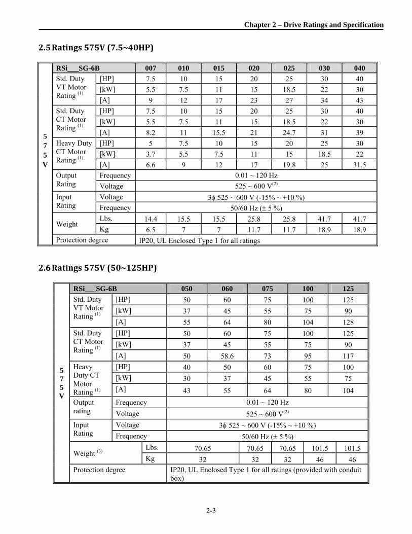
2.5 Ratings575V(7.5~40HP)
5 7 5 V
RSi___SG-6B 007 010 015 020 025 030 040
Std. Duty VT Motor Rating (1)
[HP] 7.5 10 15 20 25 30 40
[kW] 5.5 7.5 11 15 18.5 22 30
[A] 9 12 17 23 27 34 43
Std. Duty CT Motor Rating (1)
[HP] 7.5 10 15 20 25 30 40
[kW] 5.5 7.5 11 15 18.5 22 30
[A] 8.2 11 15.5 21 24.7 31 39
Heavy Duty CT Motor Rating (1)
[HP] 5 7.5 10 15 20 25 30
[kW] 3.7 5.5 7.5 11 15 18.5 22
[A] 6.6 9 12 17 19.8 25 31.5
Output Rating
Frequency 0.01 ~ 120 Hz
Voltage 525 ~ 600 V(2)
Input Rating
Voltage 3 525 ~ 600 V (-15% ~ +10 %) Frequency 50/60 Hz ( 5 %)
Weight Lbs. 14.4 15.5 15.5 25.8 25.8 41.7 41.7 Kg 6.5 7 7 11.7 11.7 18.9 18.9
Protection degree IP20, UL Enclosed Type 1 for all ratings
2.6 Ratings575V(50~125HP)
5 7 5 V
RSi___SG-6B 050 060 075 100 125
Std. Duty VT Motor Rating (1)
[HP] 50 60 75 100 125
[kW] 37 45 55 75 90
[A] 55 64 80 104 128
Std. Duty CT Motor Rating (1)
[HP] 50 60 75 100 125
[kW] 37 45 55 75 90
[A] 50 58.6 73 95 117
Heavy Duty CT Motor Rating (1)
[HP] 40 50 60 75 100
[kW] 30 37 45 55 75
[A] 43 55 64 80 104
Output rating
Frequency 0.01 ~ 120 Hz
Voltage 525 ~ 600 V(2)
Input Rating
Voltage 3 525 ~ 600 V (-15% ~ +10 %)
Frequency 50/60 Hz ( 5 %)
Weight (3) Lbs. 70.65 70.65 70.65 101.5 101.5 Kg 32 32 32 46 46
Protection degree IP20, UL Enclosed Type 1 for all ratings (provided with conduit box)
Chapter 2 – Drive Ratings and Specification
2-4
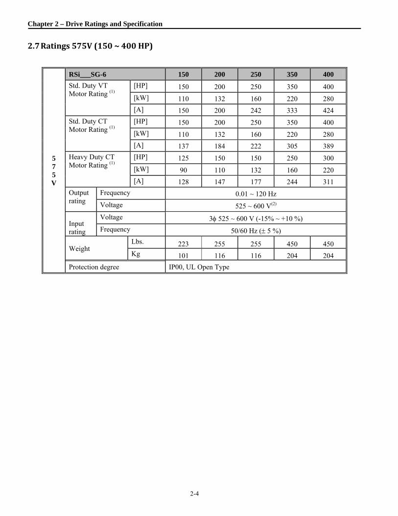
2.7 Ratings575V(150~400HP)
5 7 5 V
RSi___SG-6 150 200 250 350 400
Std. Duty VT Motor Rating (1)
[HP] 150 200 250 350 400
[kW] 110 132 160 220 280
[A] 150 200 242 333 424
Std. Duty CT Motor Rating (1)
[HP] 150 200 250 350 400
[kW] 110 132 160 220 280
[A] 137 184 222 305 389
Heavy Duty CT Motor Rating (1)
[HP] 125 150 150 250 300
[kW] 90 110 132 160 220
[A] 128 147 177 244 311
Output rating
Frequency 0.01 ~ 120 Hz
Voltage 525 ~ 600 V(2)
Input rating
Voltage 3 525 ~ 600 V (-15% ~ +10 %)
Frequency 50/60 Hz ( 5 %)
Weight Lbs. 223 255 255 450 450 Kg 101 116 116 204 204
Protection degree IP00, UL Open Type

Chapter 2 – Drive Ratings and Specification
2-5
2.8 GeneralSpecification
Cooling method Forced air cooling
Short Circuit Rating 100KA, Suitable for use on a circuit capable of delivering not more than 100,000 A(rms) Symmetrical amperes when protected by a breaker or fuse with an interrupt rating of not less than 100,000 A(rms).
Agency Approvals UL and cUL listed, CE marked
CO
NT
RO
L
Control Method V/F, Sensorless Vector, Slip Compensation, Easy Start Selectable Frequency Setting Resolution
Digital Reference: 0.01 Hz (Below 100 Hz), 0.1 Hz (Over 100 Hz) Analog Reference: 0.01 Hz / 60 Hz
Frequency Accuracy Digital: 0.01 % of Max. Output Frequency Analog: 0.1 % of Max. Output Frequency
V/F Ratio Linear, Squared Pattern, User V/F
Overload Capacity 110% per 1 min VT standard duty, 120% per 1 min CT standard duty, 150% per 1 min heavy duty
Voltage Boost Manual Voltage Boost (0 ~ 15 % programmable), Auto Boost
OP
ER
AT
ION
Operation Method Keypad / Terminal / Communication Operation Frequency Setting (Isolated)
Analog: 0~12V, -12V~ +12V, 4~20mA or 0~20mA, Pulse, Ext-PID Digital: Keypad
Inpu
t Sig
nal (
Isol
ated
)
Start Signal Forward, Reverse Multi-Step Max 18 Speeds can be set including Jog, Dwell via (4) Multi-Function TerminalsAcc/Dec Time Pattern
0.1~ 6,000 sec. Linear, U-Curve, S-Curve Selectable
Inverter Disable Interrupts the output of the drive. Jog Jog operation Fault Reset Trip status is reset when a fault indication is active.
Out
put s
igna
l Operating Status
Relay Output contacts (Isolated). (4) Form A (Ax-Cx) - AC 250V, 1A. Programmable to: Frequency Detection Level, Overload Alarm, Stall, Over Voltage, Low Voltage, Inverter Overheat/Run/Stop/Steady/Ready, Inverter Bypass, Speed Searching
Fault Output Relay Output contacts (Isolated). Form C (3A, 3C, 3B) – AC 250V 1A, DC 30V 1A
Meter/Indicator Output Voltage: (2) 0~10VDC Outputs (Non-Isolated): Choose from: Output Frequency, Output Current, Output Voltage, DC Link Voltage, Power (Watts).
Operation Functions
DC Braking, Frequency Limit, Frequency Jump, 2nd Function, Slip Compensation, Reverse Rotation Prevention, Auto Restart, Inverter Bypass, Auto-Tuning, PID Control, Flying Start, Safety Stop, Flux Braking, Low Leakage, Pre-PID, Dual-PID, MMC, Easy Start, Pre-heater

Chapter 2 – Drive Ratings and Specification
2-6
GeneralSpecification(continued)
PR
OT
EC
TIO
N Inverter Trips
Over Voltage, Low Voltage, Over Current, Ground Fault, Inverter Overheat, Motor Overheat, Output Phase Open, Overload Protection, External Fault 1, 2, Communication Error, Loss of Speed Command, Hardware Fault, Option Fault
Inverter Alarms Stall Prevention, Overload Alarm, Over Heat, Thermal Sensor Fault
Momentary Power Loss
Below 8.3 msec: Continuous operation Above 8.3 msec: Auto restart active (AFN-22) Above 1 sec: Auto restart active (AFN-22) and for high inertia loads, Safety Stop (FUN-28) set to “Yes”.
DIS
PL
AY
Keypad
Operation Information
Output Frequency, Output Current, Output Voltage, Frequency Set Value, Operating Speed, DC Link Voltage, Integrating Wattmeter, Run-Time, Last Trip Time
Trip Information
Trip Indication when a fault occurs. Maximum of five (5) faults are log along with the Last Trip Time.
EN
VIR
ON
ME
NT
Ambient Temperature -10 C (14F) ~ 40 C (104F) (Derate by 20% for use at 50C ambient)
Storage Temperature -20 C (-4F) ~ 65 C (149F)
Ambient Humidity Less Than 90 % RH Max. (Non-Condensing)
Altitude Vibration
Below 3300ft (1000m), Derate 1% (drive current) for every 300ft above 3300 ft. Below 5.9m/sec2 (=0.6g)
Application Site Pollution degree 2, No Corrosive Gas, Combustible Gas, Oil Mist, or Dust
(1) Standard duty VT motor rating based on a 110% overload for 1 minute. Standard duty CT motor rating based on a 120% overload for 1 minute. Heavy Duty motor ratings based on a 150% overload for 1 minute. Horsepower ratings based on 4-Pole motor specifications at 230V, 460V or 575V input voltages. Operation at lower input voltages or with motors with 6 or more poles may require the use of a larger drive depending on actual motor rating.
(2) Maximum output voltage will not exceed the input voltage. An output voltage less than the input voltage may be programmed if necessary.
(3) The standard conduit box attachment adds 1.8kg (4 lbs.) to the weight of the drive.

Chapter 2 – Drive Ratings and Specification
2-7
2.9 Dimensions
1) 7.5 HP, 230V
7.5 HP, 460V
BOTTOM VIEW
2.95 [75.01]
6.16 [156.49]
RIGHT SIDE VIEW
10.59 [269.01]
6.16 [156.49]
11.18 [284.00]
5.91 [150.01]
FRONT VIEW
10.59 [269.01]
11.18 [284.00]
VFD-RSI-007-SG-2B
VFD-RSI-007-SG-4B
PART NUMBER
PART NUMBER
460
VOLTS HP
7.5
230
VOLTS HP
7.5
4.67 [118.49]
3.50 [89.00]
2.01 [51.00]
1.89 [48.01]
5.83 [148.01]
0.98 DIA.KNOCKOUT HOLES(3 PLACES)
0.71 DIA.MTG. HOLES(2 PLACES)
0.24 DIA.MTG. HOLES(2 PLACES)
REMOVABLE SGLCD KEYPAD
Risk of Electric Shock
VARIABLE FREQUENCY DRIVE
WARNING
Risk of Electric Shock
Risk of Injury or Electric Shock
5.12 [130.00]
0.39 [10.01] 0.30
[7.49]

Chapter 2 – Drive Ratings and Specification
2-8
2) 10 HP ~ 15 HP, 230V
10 HP ~ 15 HP, 460V
11.18 [284.00]
10.59 [269.01]
11.18 [284.00]
10.59 [269.01]
7.17 [181.99]
7.09 [180.01]
7.87 [200.00]
BOTTOM VIEW
FRONT VIEW RIGHT SIDE VIEW
VFD-RSI-015-SG-4B 460 15
VFD-RSI-010-SG-2B
VFD-RSI-015-SG-2B
VFD-RSI-010-SG-4B
PART NUMBER
PART NUMBER
230
460
VOLTS HP
10
15
230
VOLTS HP
10
WARNING
0.24 DIA.MTG. HOLES(2 PLACES)
0.71 DIA.MTG. HOLES(2 PLACES)
REMOVABLE SGLCD KEYPAD
2.30 [58.50]
4.01 [101.75]
7.19 [182.50]
7.87 [200.00]
4.31 [109.50]
3.27 [83.01]
5.32 [135.00]
0.94 DIA.KNOCKOUT HOLE(1 PLACES)
1.37 DIA.KNOCKOUT HOLES(2 PLACES)
VARIABLE FREQUENCY DRIVE
WARNING
0.39 [10.01]
0.30 [7.49]

Chapter 2 – Drive Ratings and Specification
2-9
3) 7.5 HP ~ 15 HP, 600V
13.39 [340.00]
13.98 [354.99]
7.87 [200.00]
7.09 [180.01]
13.39 [340.00]
13.98 [354.99]
7.19 [182.50]
5.47 [138.99]
7.19 [182.50]
2.30 [58.50]
4.31 [109.50]
BOTTOM VIEW
FRONT VIEW
RIGHT SIDE VIEW
VFD-RSI-010-SG-6B
VFD-RSI-007-SG-6B
PART NUMBER
7.5600
600 10
VOLTS HP
VFD-RSI-015-SG-6B 600 15
0.24 DIA.MTG. HOLES(2 PLACES)
0.71 DIA.MTG. HOLES(2 PLACES)
REMOVABLE SGLCD KEYPAD
7.87 [200.00]
4.01 [101.75]
3.27 [83.01]
0.94 DIA.KNOCKOUT HOLE(1 PLACES)
1.37 DIA.KNOCKOUT HOLES(2 PLACES)
Risk of Injury or Electric Shock
WARNING
Risk of Electric Shock
Risk of Electric Shock
VARIABLE FREQUENCY DRIVE
0.33 [8.48]
0.39 [10.01]

Chapter 2 – Drive Ratings and Specification
2-10
4) 20 HP ~ 25 HP, 230V
20 HP ~ 25 HP, 460V
20 HP ~ 25 HP, 600V
7.91 [200.91]
4.92 [124.99]
5.75 [146.00]
BOTTOM VIEW
FRONT VIEW
RIGHT SIDE VIEW
REMOVABLECONDUIT BOX
14.57 [370.00]
7.91 [200.79]
0.98 [24.99]
2.72 [69.19]
17.89 [454.28]
15.16 [384.99]
9.84 [250.01]
9.06 [230.00]
14.57 [370.00]
15.16 [384.99]
4.13 [105.00]
2.72 [69.19]
3.21 [81.61]
17.89 [454.28]
7.91 [200.86]
REMOVABLECONDUIT BOX
VOLTS
VOLTS
VOLTS
VFD-RSI-020-SG-4B 460
VFD-RSI-025-SG-4B
PART NUMBER
VFD-RSI-020-SG-6B
VFD-RSI-025-SG-6B 600
600
460
VFD-RSI-025-SG-2B
VFD-RSI-020-SG-2B
PART NUMBER
PART NUMBER
230
230
20
25
20
HP
25
HP
25
20
HP
0.24 DIA.MTG. HOLES(2 PLACES)
0.71 DIA.MTG. HOLES
(2 PLACES)REMOVABLE SGLCD KEYPAD
5.12 [130.05]
9.84 [250.01]
2.36 [59.97]
1.38 DIA.KNOCKOUT HOLE(1 PLACES)
1.97 DIA.KNOCKOUT HOLES(2 PLACES)
VARIABLE FREQUENCY DRIVEVARIABLE FREQUENCY DRIVE
0.30 [7.49]
0.39 [10.01]

Chapter 2 – Drive Ratings and Specification
2-11
5) 30 HP ~ 40 HP, 230V
30 HP ~ 40 HP, 460V
30 HP ~ 40 HP, 600V
9.22 [234.19]
8.62 [219.00]
5.41 [137.39]
17.52 [445.01]
5.48 [139.19]
18.11 [459.99]
23.59 [599.21]
FRONT VIEW
BOTTOM VIEW
REMOVABLECONDUIT BOXREMOVABLE
CONDUIT BOX
RIGHT SIDE VIEW
17.52 [445.01]
6.99 [177.50]
9.21 [234.01]
23.59 [599.21]
5.48 [139.19] 1.34
[34.01]
9.13 [232.00]
9.29 [235.99]
18.11 [459.99]
11.97 [304.01]
11.18 [284.00]
600
600
VOLTS
VFD-RSI-040-SG-6B
VFD-RSI-030-SG-6B
PART NUMBER
40
30
HP
VOLTS
460
460VFD-RSI-040-SG-4B
VFD-RSI-030-SG-4B
PART NUMBER
40
30
HP
230
230
VOLTSPART NUMBER
VFD-RSI-030-SG-2B
VFD-RSI-040-SG-2B 40
HP
30
REMOVABLE SGLCD KEYPAD
0.71 DIA.MTG. HOLES
(2 PLACES)
0.35 DIA.MTG. HOLES(2 PLACES)
11.97 [304.01]
2.84 [72.01]
5.98 [151.99]
2.00 DIA.KNOCKOUT HOLES(3 PLACES)
VARIABLE FREQUENCY DRIVE
0.30 [7.49]
0.39 [10.01]

Chapter 2 – Drive Ratings and Specification
2-12
6) 50 HP ~ 60 HP, 460V
BOTTOM VIEW
FRONT VIEW
RIGHT SIDE VIEW
25.28 [642.11]
21.02 [533.91]
20.28 [515.11]
5.12 [130.00]
11.81 [299.97]
7.48 [189.99]
20.28 [515.11]
21.02 [533.91]
25.28 [642.01]
5.12 [130.00]
10.46 [265.68]
7.09 [179.98]
10.46 [265.68]
REMOVABLECONDUIT BOX
REMOVABLECONDUIT BOX
6.24 [158.50]
PART NUMBER
VFD-RSI-050-SG-4B
VOLTS
460 50
HP
60460VFD-RSI-060-SG-4B
6.43 [163.40]
6.24 [158.50]
0.35 DIA.MTG. HOLES
(2 PLACES)
REMOVABLE SGLCD KEYPAD
0.35 DIA.MTG. HOLES(2 PLACES)
8.87 [225.22]
7.09 [179.98]
11.81 [299.97]
2.37 [60.07]
O.866 DIA.KNOCKOUT HOLES(5 PLACES)
3.20 DIA.KNOCKOUT HOLES(3 PLACES)
2.37 [60.07]
3.54 [89.99]
WARNINGWARNING
VARIABLE FREQUENCY DRIVE
2.17 [54.99] 0.37
[9.40]

Chapter 2 – Drive Ratings and Specification
2-13
7) 75 HP, 460V
VARIABLE FREQUENCY DRIVE
7.09 [179.98]
2.37 [60.07]
7.09 [179.98]
2.37 [60.07]
11.81 [299.97]
11.81 [299.97]
7.48 [189.99]
BOTTOM VIEW
FRONT VIEW
21.02 [533.91]
20.28 [515.11]25.28
[642.01]
11.52 [292.61]
6.24 [158.50]
REMOVABLECONDUIT BOX
0.35 DIA.MTG. HOLES
(2 PLACES)
5.12 [130.00]
25.28 [642.01]
21.02 [533.91]
20.28 [515.11]
460
VOLTS
3.20 DIA.KNOCKOUT HOLES(3 PLACES)
9.94 [252.45]
3.54 [89.99]
7.50 [190.40]
VFD-RSI-075-SG-4B
PART NUMBER
5.12 [130.00]
O.866 DIA.KNOCKOUT HOLES(5 PLACES)
0.35 DIA.MTG. HOLES(2 PLACES)
RIGHT SIDE VIEW
REMOVABLECONDUIT BOX
6.24 [158.50]
75
HP
WARNINGWARNING
REMOVABLE SGLCD KEYPAD
11.52 [292.61]

Chapter 2 – Drive Ratings and Specification
2-14
8) 50 HP ~ 75 HP, 600V
11.52 [292.61]
5.12 [129.95]
5.12 [130.00]
11.81 [299.97]
11.52 [292.61] 7.50
[190.40]
6.24 [158.50]
7.48 [189.99]
11.81 [299.97]
20.28 [515.11]
21.02 [533.91]
20.28 [515.11]
21.02 [533.91]
25.28 [642.01]
FRONT VIEW
BOTTOM VIEW
RIGHT SIDE VIEW
25.28 [642.01]
REMOVABLECONDUIT BOX
REMOVABLECONDUIT BOX
600
600
VOLTS
VFD-RSI-060-SG-6B
VFD-RSI-050-SG-6B
PART NUMBER
60
HP
50
VFD-RSI-075-SG-6B 600 75
6.24 [158.50]
2.37 [60.07]
7.09 [179.98]
3.54 [89.99]
9.94 [252.45]
2.37 [60.07]
7.09 [179.98]
O.866 DIA.KNOCKOUT HOLES(5 PLACES)
3.20 DIA.KNOCKOUT HOLES(3 PLACES)
0.35 DIA.MTG. HOLES
(2 PLACES)
REMOVABLE SGLCD KEYPAD
0.35 DIA.MTG. HOLES(2 PLACES)
VARIABLE FREQUENCY DRIVE
WARNINGWARNING
2.17 [54.99] 0.37
[9.40]

Chapter 2 – Drive Ratings and Specification
2-15
9) 100 HP ~ 125 HP, 460V
100 HP ~ 125 HP, 600V
RIGHT SIDE VIEW
FRONT VIEW
BOTTOM VIEW
TOP VIEW
8.66 [219.99]
13.29 [337.57]
8.66 [219.99]
14.57 [370.00]
23.09 [586.51]
24.02 [610.01]
23.09 [586.51]
24.02 [610.01]
7.23 [183.59]
13.29 [337.57]
14.57 [370.00]
6.15 [156.26]
13.29 [337.57]
9.45 [239.98]
7.23 [183.59]
12.03 [305.46]
8.80 [223.52]
6.91 [175.49]
30.22 [767.51]
7.09 [180.01]
30.22 [767.51]
REMOVABLECONDUIT BOX
REMOVABLECONDUIT BOX
460
VOLTS HP
100
460 125
PART NUMBER
VFD-RSI-100-SG-4B
VFD-RSI-125-SG-4B
REMOVABLE SGLCD KEYPAD
0.39 DIA.MTG. HOLES(2 PLACES)
0.35 DIA.MTG. HOLES(2 PLACES)
14.57 [370.00]
2.56 [65.00]
9.45 [239.98]
2.56 [65.00]
2.99 DIA.KNOCKOUT HOLES(3 PLACES)
O.86 DIA.KNOCKOUT HOLES(5 PLACES)
VFD-RSI-125-SG-6B
PART NUMBER
VFD-RSI-100-SG-6B
600 125
600
VOLTS
100
HP
VARIABLE FREQUENCY DRIVE
WARNING
2.95 [75.01]
0.61 [15.49]

Chapter 2 – Drive Ratings and Specification
2-16
10) 150 HP ~ 200 HP, 460V
150 HP, 600V
RIGHT SIDE VIEW
FRONT VIEW
BOTTOM VIEWTOP VIEW
15.00 [381.08]
20.08 [510.03]
30.85 [783.59]
29.88 [759.00]
30.85 [783.59]
16.64 [422.61]
20.08 [510.03]
20.08 [510.03]
29.88 [759.00]
16.64 [422.63]
16.64 [422.61]
13.78 [350.01]
460
460
VOLTS
VOLTS
600
VFD-RSI-150-SG-4
VFD-RSI-200-SG-4
PART NUMBER
VFD-RSI-150-SG-6
PART NUMBER
150
150
HP
200
HP
0.43 DIA.MTG. HOLES(2 PLACES)
REMOVABLE SGLCD KEYPAD
0.43 DIA.MTG. HOLES(2 PLACES)
3.13 [79.50]
2.55 [64.77]
0.34 [8.61]
VARIABLE FREQUENCY DRIVEVARIABLE FREQUENCY DRIVE
WARNINGWARNING
VARIABLE FREQUENCY DRIVEVARIABLE FREQUENCY DRIVE
WARNINGWARNING
Chapter 2 – Drive Ratings and Specification
2-17
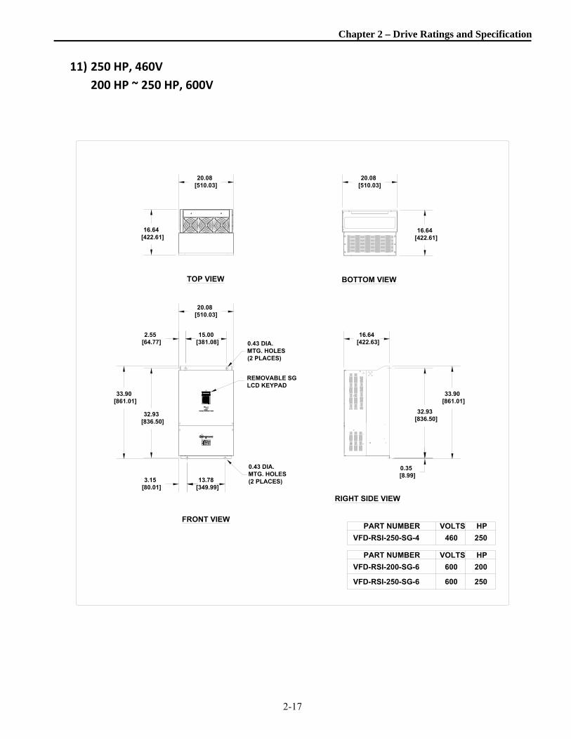
11) 250 HP, 460V
200 HP ~ 250 HP, 600V
RIGHT SIDE VIEW
FRONT VIEW
BOTTOM VIEWTOP VIEW
16.64 [422.63]
15.00 [381.08]
20.08 [510.03]
32.93 [836.50]
16.64 [422.61]
20.08 [510.03]
13.78 [349.99]
33.90 [861.01]
33.90 [861.01]
32.93 [836.50]
20.08 [510.03]
16.64 [422.61]
460
VOLTS
VOLTS
600
600
VFD-RSI-250-SG-4
PART NUMBER
VFD-RSI-200-SG-6
VFD-RSI-250-SG-6
PART NUMBER
250
250
200
HP
HP
REMOVABLE SGLCD KEYPAD
0.43 DIA.MTG. HOLES(2 PLACES)
0.43 DIA.MTG. HOLES(2 PLACES)
2.55 [64.77]
3.15 [80.01]
0.35 [8.99]
VARIABLE FREQUENCY DRIVEVARIABLE FREQUENCY DRIVE
WARNINGWARNING

Chapter 2 – Drive Ratings and Specification
2-18
12) 350 HP ~ 400 HP, 460V
350 HP ~ 400 HP, 600V
RIGHT SIDE VIEW
FRONT VIEW
BOTTOM VIEWTOP VIEW
27.17 [690.12]
17.70 [449.61]
17.70 [449.61]
27.17 [690.12]
11.43 [290.42]
42.44 [1078.00]
41.08 [1043.51]
17.70 [449.61]
3.19 [81.03]
10.40 [264.03]
27.17 [690.12]
VARIABLE FREQUENCY DRIVEVARIABLE FREQUENCY DRIVE
41.08 [1043.51]
42.44 [1078.00]
460
460
VOLTS
VOLTS
600
600
VFD-RSI-350-SG-4
VFD-RSI-400-SG-4
PART NUMBER
VFD-RSI-350-SG-6
VFD-RSI-400-SG-6
PART NUMBER
350
400
350
HP
400
HP
11.43 [290.42]
10.40 [264.03]
0.35 [8.99]
0.43 DIA.MTG. HOLES(2 PLACES)
REMOVABLE SGLCD KEYPAD
0.43 DIA.MTG. HOLES(2 PLACES)
WARNINGWARNING
2.15 [54.64]

Chapter 2 – Drive Ratings and Specification
2-19
13) 500 HP, 460V
RIGHT SIDE VIEW
FRONT VIEW
BOTTOM VIEWTOP VIEW
30.39 [771.91]
17.40 [441.99]
30.39 [771.91]
9.85 [250.09]
44.90 [1140.36]
43.70 [1109.85]
44.90 [1140.46]
43.70 [1109.85]
9.85 [250.09]
17.40 [442.01]
5.35 [135.86]
17.40 [441.99]
30.39 [771.91]
9.85 [250.09]
9.85 [250.09]
PART NUMBER
VFD-RSI-500-SG-4 460
VOLTS
500
HP
0.43 DIA.MTG. HOLES(2 PLACES)
REMOVABLE SGLCD KEYPAD
0.43 DIA.MTG. HOLES(2 PLACES)
0.52 [13.11]
WARNINGWARNING
VARIABLE FREQUENCY DRIVEVARIABLE FREQUENCY DRIVE

Chapter 2 – Drive Ratings and Specification
2-20
14) 600 HP ~ 700 HP, 460V
50.06 [1271.60]
51.25 [1301.83]
36.30 [922.02]
19.49 [495.00]
6.73 [170.99]
11.42 [289.99]
11.42 [289.99]
WARNINGWARNING
19.49 [495.00]
6.73 [171.04]
36.30 [922.02]
VARIABLE FREQUENCY DRIVE
11.42 [289.97]
11.42 [289.97]
51.28 [1302.44]
50.06 [1271.60]
19.49 [495.00]
36.30 [922.02]
TOP VIEW
FRONT VIEW
BOTTOM VIEW
RIGHT SIDE VIEW
460VFD-RSI-600-SG-4 600
VOLTSPART NUMBER HP
VFD-RSI-700-SG-4 460 700
0.39 [9.93]
0.51 DIA.MTG. HOLES(3 PLACES)
REMOVABLE SGLCD KEYPAD
0.51 DIA.MTG. HOLES(3 PLACES)

Notes :


3-1
Cooling fan
Cooling air Leave space enough to allow cooled air flowing easily between wiring duct and the unit.
Chapter3. Installation
3.1 InstallationPrecautions 1) Handle the drive with care to prevent damage to the plastic components. Do not hold the drive by the front
cover. 2) Do not mount the drive in a location where excessive vibration (5.9 m/sec2 or less) is present such as installing
the drive on a press or other moving equipment. 3) Install in a location where temperature is within the permissible range (-10~40C). 4) The drive will be very hot during operation. Install it on a non-combustible surface. 5) Mount the drive on a flat, vertical and level surface. Drive orientation must be vertical (top up) for proper heat dissipation. When mounting the drive in a location (or enclosure) WITHOUT additional forced ventilation leave sufficient air space clearances around the drive.
< 30 HP > 40 HP
A 4" 20"
B 2" 8"
Temp checking point
Temp checking point
2 inch
2 inch
2 inch
Drive
Drive
A
A
BB

Chapter 3 - Installation
3-2
6) Do not mount the drive in direct sunlight or near other heat sources. 7) The drive shall be mounted in a Pollution Class 2 environment. If the drive is going to be installed in an environment with a high probability of dust, metallic particles, mists, corrosive gases, or other contaminates, the drive must be located inside the appropriate electrical enclosure of the proper NEMA or IP rating. 8) When two or more drives are installed or a ventilation fan is mounted in the drive panel, the drives and ventilation fan must be installed in proper positions with extreme care taken to keep the ambient temperature of the drives below the permissible value. If they are installed in improper positions, the ambient temperature of the drives will rise. .
9) Install the drive using appropriate sized screws or bolts to insure the drive is firmly fastened.
CAUTION
■ Risk of Electric Shock
More than one source of power may be present. More than one disconnect switch may be required to de-energize the equipment before servicing.
Inverter
GOOD (O) BAD (X)
Inverter
Cooling fan
Panel Panel
Inverter
Inverter
[When installing several inverters in a panel]
Ventilating fan
GOOD (O) BAD (X)
[When installing a ventilating fan in a panel]

Chapter 3 - Installation
3-3
3.2 Wiring
3.2.1 BasicWiring1) For 7.5~40 HP (5.5~30kW)
Control Circuit
Main Power Circuit
AC Input
50/60 Hz
UVW
G
R(L1)S(L2)T(L3)
N(-)
DB Unit(Optional)
DB Resistor (Optional)
3
MCCB(Option)
M1
M2
M3
M4
M6
M8
M7
MOTOR
Programmable Digital Input 1(Speed L)
Programmable Digital Input 2(Speed M)
Programmable Digital Input 3(Speed H)
Fault Reset (RST)
Jog Frequency Reference (JOG)
Forward Run command (FX)
Reverse Run command (RX)
Common Terminal
P2(+) P1(+)
DC Bus Choke (Optional )
Dynamic Braking Unit (Optional)
P N B1 B2
DC Bus Choke DB Resistor
M5 Inverter Disable (BX)
V+
V1
5G
V-
I
Analog Power Source (+12V)
+ -
+ -
Analog Power Source (-12V)
Frequency reference (0~20mA or 4~20mA)
Frequency reference (0~12V,V1S : -12~12V)
Frequency reference common terminal
S1
S0
5G
Output Frequency Meter Output Voltage Meter Common for output meter signal
Max. output voltage : 12V Source Max. : 30mA Sink Max. : 20mA
5G
B0
A0 Frequency Reference (Pulse : 0 ~ 100kHz)
Common for Frequency Reference (Pulse)
5G
NT External motor thermal detection
A1
C1 A2
C2
A3
C3 A4
C4
C -
C+ CM
RS485 Signal
RS485 Common
CM
Note: 1) 5G is Common Ground for Analog Input and Outputs. 2) Use terminal V1 for (0~12V) input or V1S for (-12 ~12V input))
Fault Contact Output 250VAC (DC30V), 1A
3A
3C
3B
SA
SB Safety Function (NC) 600V only

Chapter 3 - Installation
3-4
2) For 50~125HP (37~90KW) and 500~700HP (315~450kW)
AC Input
50/60 Hz
U
V W
G
R(L1)S(L2) T(L3)
N(-)
DB Unit(Optional)
DB Resistor (Optional)
3
MCCB(Option)
M1
M2
M3
M4
M6
M8
M7
MOTOR
Programmable Digital Input 1(Speed L)
Programmable Digital Input 2(Speed M)
Programmable Digital Input 3(Speed H)
Fault Reset (RST)
Jog Frequency Reference (JOG)
Forward Run command (FX)
Reverse Run command (RX)
Common Terminal
P2(+)P1(+)
DC Bus Choke (Optional )
Dynamic Braking Unit(Optional)
P N B1 B2
DC Bus Choke DB Resistor
M5 Inverter Disable (BX)
V+
V1
CM
V-
I
Analog Power Source (+12V)
+ -
+ -
Analog Power Source (-12V)
Frequency reference (0~20mA or 4~20mA)
Frequency reference (0~12V,V1S : -12~12V)
Frequency reference common terminal
S1
S0
5G
Output Frequency Meter
Output Voltage Meter
Common for output meter signal
CM
B0
A0
Common for Frequency Reference
Frequency Reference (Pulse : 0 ~ 100kHz)
5G
ET External motor thermal detection
A1
C1
A2
C2
A3
C3
A4
C4
C-
C+
CM
RS485 Signal
RS485 Common
CM
Note : 1) CM is Common Ground for Analog Input. 5G is Common Ground for Analog Output. 2) Use terminal V1 for (0~12V input) or V1S (-12 ~ 12V input).
Programmable Relay Outputs
Fault Contact Output 250VAC (DC30V), 1A
3A
3C
3B
SA
SB Safety Function (NC) 600V only
Main Power Circuit
Control Circuit
250 VAC, 1A

Chapter 3 - Installation
3-5
3) For 150~400HP (110~280kW)
AC Input
50/60 Hz
U
V W
G
R(L1)S(L2)T(L3)
DB Unit(Optional)
DB Resistor (Optional)
3
M1
M2
M3
M4
M6
M8
M7
MOTOR
Programmable Digital Input 1(Speed L)
Programmable Digital Input 2(Speed M)
Programmable Digital Input 3(Speed H)
Fault Reset (RST)
Jog Frequency Reference (JOG)
Forward Run command (FX)
Reverse Run command (RX)
Common Terminal
P2(+)
Dynamic Braking Unit(Optional)
P N B1 B2
DB Resistor
M5 Inverter Disable (BX)
V+
V1
CM
V-
I
Analog Power Source (+12V)
+ -
+ -
Analog Power Source (-12V)
Frequency reference (0~20mA or 4~20mA)
Frequency reference (0~12V,V1S : -12~12V)
Frequency reference common terminal
S1
S0
5G
Output Frequency Meter
Output Voltage Meter
Common for output meter signal
CM
B0
A0
Common for Frequency Reference
Frequency Reference (Pulse : 0 ~ 100kHz)
5G
ET External motor thermal detection
A1
C1
A2
C2
A3
C3
A4
C4
C-
C+
CM
RS485 Signal
RS485 Common
CM
Note : 1) CM is Common Ground for Analog Input 5G is Common Ground for Analog Output. 2) Use terminal V1 for (0~12V input) or V1S (-12 ~ 12V input). 3) DC Reactor is built in the inverters for 150~400HP (110~280kW).
Programmable Relay Outputs
DC Reactor(Built-in)
N(-)
Fault Contact Output 250VAC (DC30V), 1A
3A
3C
3B
SA
SB Safety Function (NC) 600V only
Main Power Circuit
Control Circuit
250 VAC, 1A

Chapter 3 - Installation
3-6
4) Power Terminals: Screw Terminals
7.5 ~ 40 HP (230V/460V/575V)
R(L1) S(L2) T(L3) G P1(+) P2(+) N(-) U V W
Bus Bar Terminals 50 ~ 125 HP (460V/575V) / 500 ~ 700 HP (460V)
R(L1) S(L2) T(L3) P1(+) P2(+) N(-) U V W
Bus Bar Terminals 150 ~ 400 HP (460V)
R(L1) S(L2) T(L3) P2(+) N(-) U V W Note) P1 terminal is not provided for wiring.
Symbol Description R(L1), S(L2), T(L3) AC Line Voltage Input G Earth Ground
P1(+), P2(+) External DC Reactor (P1-P2) Connection Terminals (Jumper must be removed).
P2(+), N(-) DB Unit (P2-N) Connection Terminals U, V, W 3 Phase Power Output Terminals to Motor
Jumper
Jumper

Chapter 3 - Installation
3-7
5) Control circuit terminal 7.5 ~ 40 HP (230V/460V/575V)
50 ~ 700 HP (460V), 50 ~ 150 HP (575V)
A0 B0 5G 5G S0 S1
V+ V1 5G V- I NT
C+CM C- M6 24 M7M8
M1CMM2 M3 24 M4M53A 3C 3B A1 C1 A2 C2 A3 C3 A4 C4
C+CM C- M6 24 M7M8
M1CMM2 M3 24 M4M53A 3C 3B A1 C1 A2 C2 A3 C3 A4 C4
CM NC 5G 5G ET S0 S1
V+ V1 CM V- I A0 B0

Chapter 3 - Installation
3-8
Type Symbol Name Description
Inpu
t sig
nal D
igit
al I
nput
s F
unct
ions
(de
faul
ts)
Add
itio
nal F
unct
ions
(I/
O-2
0 ~
I/O
-27)
M1, M2, M3
Multi-Function Input 1, 2, 3
Defines Multi-Function Inputs. (Factory setting: Multi-Step Frequency 1, 2, 3)
FX [M7] Forward Run Command
Forward Run When Closed and Stopped When Open.
RX [M8] Reverse Run Command
Reverse Run When Closed and Stopped When Open.
JOG [M6] Jog Frequency Reference
Runs at Jog Frequency when the Jog Signal is ON. The Direction is set by the FX (or RX) Signal. Jog Speed is set with I/O-30.
BX [M5] Inverter Disable When the BX Signal is ON the output of the drive is turned off. When the application uses an Electrical Brake to Stop, BX can be used to turn off the output signal when the brake is applied.
RST [M4] Fault Reset Used for fault reset.
CM Sequence Common (NPN) / 24V Com
Common terminal for NPN contact input and also common for an external 24V supply.
24 Sequence Common (PNP) / Ext. +24VDC supply
24 V terminal for PNP contact input. Can also be used as a 24VDC external power supply (maximum output: +24V, 50mA).
Ana
log
Fre
quen
cy S
etti
ng V+, V-
Frequency Setting Power (+12V,-12V)
Power supply for Analog Frequency Setting. (maximum output: +12V, 100mA, -12V, 100mA.)
V1 Frequency Reference (Voltage)
Used by a DC 0-12V or –12~ 12 V input to set the Frequency
Reference. (Input Resistance 20 KΩ).
I Frequency Reference (Current)
Used by a 0/4-20mA input to set the frequency reference.
(Input Resistance 249 Ω).
A0, B0 Frequency setting (Pulse)
Used by a pulse input to set the frequency reference.
5G (7.5~40HP)
CM (50~700HP)
Frequency Setting Common Terminal
Common terminal for Analog Frequency Reference signals.
Motor
Thermal
Detection
NT (7.5 ~ 40HP)
ET (50 ~125HP) External motor thermal detection
Motor thermal sensor input. Used to prevent motor from overheating by using a NTC or PTC thermal sensor.
RS-485/ Modbus terminal
C+, C- RS-485/Modbus signal High, Low
RS-485/Modbus signals (See Chapter 9 in this manual for more details.)
CM RS-485/Modbus common
Common Gnd. Terminal for RS-485/Modbus interface.
Out
put s
igna
l Voltage S0, S1 (5G)
Progammable Voltage Output for external monitoring
Voltage output for one of the following: Output Frequency, Output Current, Output Voltage, DC Link Voltage, Power (Watts). Default is set to Output Frequency. (Maximum Output Voltage and Output Current are 0-12V and 30mA).
Contact 3A, 3C, 3B
Fault Contact Output
Energizes when a fault is present. (AC250V, 1A; DC30V, 1A) Normal: 3B-3C Closed (3A-3C Open) Fault: 3A-3C Closed (3B-3C Open)
A1~4, C1~4
Multi-Function Output Relays
User defined: Multi-Function Output terminal settings (AC250V, 1A; DC30V, 1A)

Chapter 3 - Installation
3-9
3.2.2 WiringInputandOutputPowerTerminals
General Power Wiring Precautions 1) The internal circuits of the drive will be damaged if the incoming power is connected and applied to the output terminals (U, V, W). If a drive bypass contactor is used, extreme care must be taken so that input voltage is never applied to the output terminals. An electrical or mechanical interlock of MC1 and MC2 is required for Inverter Bypass Operation. 2) Use ring terminals with insulated caps when wiring the input power and motor wiring.
3) Do not leave wire fragments inside the drive. Wire fragments can cause drive faults, short circuits, and other malfunctions. 4) Motor torque may drop when operating at low frequencies and with a long wire run between drive and motor. 5) The cable length between inverter and motor should be less than 100 feet. Due to increased leakage capacitance between cables, overcurrent protective feature may operate or equipment connected to the output side may malfunction. If cable length between drive and motor is greater than 100 ft. see Motor Lead Length Specifications in this section. 6) The main power circuit of the drive may produce high frequency noise, and can hinder communication equipment near the drive. Do not run control wires in the same conduit or raceway with power wiring. To reduce noise, install line noise filters on the input and or output side of the drive. 7) Power wiring to the motor must have the maximum possible separation from all other power wiring. Do not run output wires in the same conduit as other wiring. 8) Cross wires at right angles whenever power and control wiring cross. 9) Do not use power factor capacitor, surge arrestors, or RFI filters on the output side of the drive. Doing so may damage the drive or the added components. 10) The input phase voltages must be balanced within 2%. Large input phase voltage imbalances can cause significantly imbalanced input currents that can result in excessive heating of the input diodes and the DC bus capacitors. 11) Always check whether the LCD keypad is off and the charge lamp for the power terminal is OFF before wiring terminals. The DC bus capacitors may hold high-voltage even after the power is disconnected. Use caution to prevent the possibility of personal injury.
Grounding
1) The power source must be grounded. DO NOT USE AN UNGROUNDED source of supply. 2) DO NOT CONNECT THE DRIVE to a Corner Grounded Delta source of supply. 3) The drive contains high power and high frequency switching devices, leakage current may flow between
the drive and ground. Ground the drive to avoid electrical shock. 4) Connect only to the dedicated ground terminal of the drive. Do not use the case or the chassis screw for
grounding. 5) If multiple drives are installed near each other, each must be connected to ground directly. Take care not to
form a ground loop between the drives and the grounding location. 6) The protective earth conductor must be the first one in being connected and the last one in being
disconnected. 7) The grounding wire shall comply with all local regulations. As a minimum, the grounding wire should
meet the specifications listed below. The grounding wire should be as short as possible and should be connected to a ground point as near as possible to the drive.

Chapter 3 - Installation
3-10
Drive Capacity Grounding Wire Sizes, AWG or kcmil (mm²) 230V Class 460VClass 600VClass
7.5 ~ 10 HP 10 (5.5) 12 (3.5) 14 (2.5)
15 ~ 20 HP 6 (14) 8 (8) 12 (3.5)
25 ~ 40 HP 4 (22) 6 (14) 8 (8)
50 ~ 75 HP - 4 (22) 6 (14)
100 ~ 125 HP - 2 (38) 4 (22)
150 ~ 200 HP - 1/0 (60) 2 (38)
250 ~ 400 HP - 4/0 (100) 1/0 (60)
500 ~ 600 HP - 300 (150) -
700 HP - 400 (200) -
Use of Isolation Transformers and Line Reactors In most cases, the SG drive may be directly connected to a power source. However in the following cases a properly sized isolation transformer or a 3% or 5% line reactor should be used to minimize the risk of drive malfunction. - When the source capacity exceeds ten (10) times the KVA rating of the drive. - When power factor capacitors are located on the input source supplying the drive. - When the power source experiences frequent power transients and/or voltage spikes.
- When the power source supplying the SG drive also supplies other large electrical devices such as DC drives that contain rectifiers or other switching devices. - When the drive is powered from an ungrounded (floating) Delta connected source. In this case, establish a grounded secondary. A drive isolation transformer utilizing a grounded (solid or resistance grounded) secondary should be used. Other means of establishing a ground may be used.
Motor Lead Length Specifications
Excessive motor lead lengths may adversely affect the performance of the motor. The voltage of the pulses at the motor terminals can be almost double the input voltage of the drive. This in turn can cause additional stress on the motor insulation and shorten the life of the motor. The motor manufacturer should be consulted regarding the specifications of the motor insulation. A filter may be required to be added to the output of the drive depending on the lead lengths from the drive to the motor. Contact Benshaw for assistance with selecting the appropriate filter. See the table below.
PWM Carrier Frequency Motor Lead Length Type of Filter
Default Frequency or lower 50 ft. to 300 ft. 1.5% or 3% Load Reactor 300 ft. to 1500 ft. LRC Filter (dV/dT)
>1500 ft. Sine Wave Filter

Chapter 3 - Installation
3-11
If an output filter is used it is recommended that the output filter is wired as follows:
- Wiring distance from drive output to filter input should not exceed 5 meters (16.4 feet). - Wiring distance from filter to motor should not exceed the distance in the preceding table.
3.2.3 InterferenceSuppressionMeasures
Electrical and electronic devices are capable of influencing or disturbing each other through their connection cables or other intended and unintended metallic connections. Interference suppression measures (electromagnetic compatibility) consist of two elements: raising interference resistance and suppressing interference emission. Correct installation of the drive in conjunction with local interference suppression measures has a crucial effect on minimizing or suppressing mutual interference. The following guidelines assume a power source that is not already contaminated by high frequency interference. Other measures may be necessary to reduce or suppress interference if the power source is already contaminated. Refer to Appendix C for more information. - When dealing with RFI (radio frequency interference), the surface area of the conductors is a more critical consideration than its cross sectional area. Since high frequency interference currents tend to stay towards the outer surface (skin effect), braided copper tapes of equal cross section should be used. - A central grounding (or earthing) point should be used for interference suppression. Route the ground cables radially from this point (star connection). Avoid making any ground loops that may lead to increased interference. The drive and all components used for interference suppression, particularly the shield of the motor cable, should be connected over as large a surface area as possible when connecting it to ground. Remove the paint from contact surfaces if necessary to ensure a good electrical connection. - Take care not to damage the shield’s cross section and verify the continuity of the shield when splicing wires. Splices raise the RF resistance of the shield and can cause RF to radiate rather than continue in the shield. Shields, particularly those on control cables, must not be routed through pin contacts (pluggable connectors). When shielded cables must pass through a plug connection, use the metallic hand guard of the plug for the continuation of the shield. It is strongly recommended that the shield be uninterrupted whenever possible.
U,V,W
Drive Motor
Within 16.4ft Per Table
Sur
ge
Sup
pres
sor
filte
r
Chapter 3 - Installation
3-12
- Use a shielded motor cable that is grounded over a large surface area at both ends. The shield on this cable should be uninterrupted. If a shielded motor cable cannot be used, the unshielded motor lines should be laid in a metal conduit or duct which is uninterrupted and grounded at both ends. When selecting shielded cable for use as motor leads it is important to select a cable that is designed for operation at the frequencies and power levels involved with a variable frequency drive. Improper selection of motor cables can cause high potential to exist on the shield. This could cause damage to the drive or other equipment and can pose a safety hazard. Many cable manufactures have shielded drive cable available. The following cables are acceptable for this purpose: OLFlex Series 150CY, 110CY, 110CS, 100CY, 100CS, and 540CP. Siemens CordaflexSM is also acceptable. Some of these cables are VDE-approved only; others carry VDE, UL, CSA, or a combination of these ratings. Be sure to confirm that the cables meet the appropriate local regulatory requirements. OLFlex cables are available from OLFlex Wire & Cable, 30 Plymouth Street, Fairfield NJ 07004, 800-774-3539 Cordaflex cables are available from Siemens Energy and Automation, Inc., Power Cables, 3333 State Bridge Road, Atlanta GA 30202, 800-777-3539 - If the installation requires the use of an output reactor, the reactor, as with a line filter, should be placed as close as possible to the drive. - Low voltage control wires longer than 1 meter (3ft) must use shielded cable and the shield must be terminated at the proper CM connection. Note that the connection to the CM rather than earth ground is allowed because the RSi SG drive has isolated control inputs. If the signal run exceeds 9 meters (30ft), a 0-20mA or 4-20mA signal should be used as it will have better noise immunity than a low-level voltage signal. - Other loads connected to the power source may produce voltage transients (spikes) that may interfere with or damage the drive. Input line reactors or input filters can be used to protect the drive from these transients. - If the drive is operated from switchgear devices or is in close proximity to switchgear devices (in a common cabinet), the following procedures are recommended as a precaution to prevent these devices from interfering with the drives operation. - Wire the coils of DC devices with freewheeling diodes. The diodes should be placed as close as possible to the physical coil of the device. - Wire the coils of AC devices with RC type snubber networks. Place the snubber as close as possible to the physical coil of the device. - Use shielded cables on all control and monitoring signals. - Route distribution cables (for example, power and contactor circuits) separately from the drive's control and monitoring signal cables.

Chapter 3 - Installation
3-13
3.2.4 TerminalLayout Screw Terminals 7.5 ~ 40 HP (230V/460V/575V)
R(L1) S(L2) T(L3) G P1(+) P2(+) N(-) U V W
Bus Bar Terminals 50 ~ 125 HP (460V/575V) / 500 ~ 700 HP (460V)
R(L1) S(L2) T(L3) P1(+) P2(+) N(-) U V W
Bus Bar Terminals 150 ~ 400 HP (460V/575V)
R(L1) S(L2) T(L3) P2(+) N(-) U V W Note) P1 terminal is not provided for wiring.
Power and Motor Connection Example (7.5~40 HP drives)
R(L1) S(L2) T(L3) G P1(+) P2(+) N(-) U V W
Jumper
Jumper
Power supply must be connected to the R, S, and T terminals. Connecting it to the U, V, and W terminals causes internal damages to the inverter. Arranging the phase sequence is not necessary.
Motor should be connected to the U, V, and W terminals. If the forward command (FX) is on, the motor should rotate counter clockwise when viewed from the load or shaft side of the motor. If the motor rotates in the reverse, switch the U and V terminals.
Ground Ground
Chapter 3 - Installation
3-14
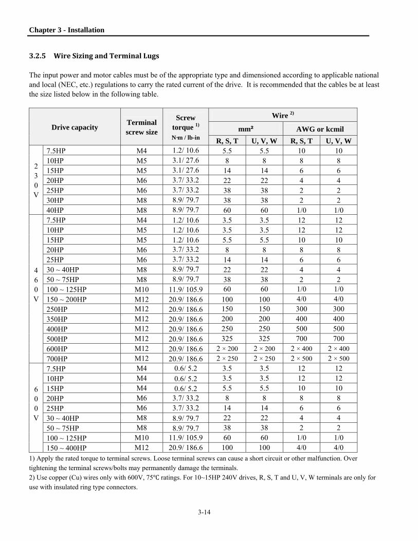
3.2.5 WireSizingandTerminalLugs The input power and motor cables must be of the appropriate type and dimensioned according to applicable national and local (NEC, etc.) regulations to carry the rated current of the drive. It is recommended that the cables be at least the size listed below in the following table.
Drive capacity Terminal screw size
Screw torque 1)
N·m / lb-in
Wire 2)
mm² AWG or kcmil
R, S, T U, V, W R, S, T U, V, W
2 3 0 V
7.5HP M4 1.2/ 10.6 5.5 5.5 10 10 10HP M5 3.1/ 27.6 8 8 8 8 15HP M5 3.1/ 27.6 14 14 6 6 20HP M6 3.7/ 33.2 22 22 4 4 25HP M6 3.7/ 33.2 38 38 2 2 30HP M8 8.9/ 79.7 38 38 2 2 40HP M8 8.9/ 79.7 60 60 1/0 1/0
4 6 0 V
7.5HP M4 1.2/ 10.6 3.5 3.5 12 12 10HP M5 1.2/ 10.6 3.5 3.5 12 12 15HP M5 1.2/ 10.6 5.5 5.5 10 10 20HP M6 3.7/ 33.2 8 8 8 8 25HP M6 3.7/ 33.2 14 14 6 6 30 ~ 40HP M8 8.9/ 79.7 22 22 4 4 50 ~ 75HP M8 8.9/ 79.7 38 38 2 2 100 ~ 125HP M10 11.9/ 105.9 60 60 1/0 1/0 150 ~ 200HP M12 20.9/ 186.6 100 100 4/0 4/0
250HP M12 20.9/ 186.6 150 150 300 300 350HP M12 20.9/ 186.6 200 200 400 400 400HP M12 20.9/ 186.6 250 250 500 500
500HP M12 20.9/ 186.6 325 325 700 700 600HP M12 20.9/ 186.6 2 × 200 2 × 200 2 × 400 2 × 400 700HP M12 20.9/ 186.6 2 × 250 2 × 250 2 × 500 2 × 500
6 0 0V
7.5HP M4 0.6/ 5.2 3.5 3.5 12 12 10HP M4 0.6/ 5.2 3.5 3.5 12 12 15HP M4 0.6/ 5.2 5.5 5.5 10 10
20HP M6 3.7/ 33.2 8 8 8 8 25HP M6 3.7/ 33.2 14 14 6 6 30 ~ 40HP M8 8.9/ 79.7 22 22 4 4
50 ~ 75HP M8 8.9/ 79.7 38 38 2 2 100 ~ 125HP M10 11.9/ 105.9 60 60 1/0 1/0 150 ~ 400HP M12 20.9/ 186.6 100 100 4/0 4/0
1) Apply the rated torque to terminal screws. Loose terminal screws can cause a short circuit or other malfunction. Over
tightening the terminal screws/bolts may permanently damage the terminals.
2) Use copper (Cu) wires only with 600V, 75 ratings. For 10~15HP 240V drives, R, S, T and U, V, W terminals are only for
use with insulated ring type connectors.

Chapter 3 - Installation
3-15
3.2.6 ControlCircuitWiring
(1) Wiring Precautions CM and 5G terminals are isolated from each other. Digital Input Terminals are rated 24 VDC. Do not apply 120 Vac directly to control circuit input terminals.
Use shielded wires or twisted wires for all control circuit wiring, and separate these wires from the main power circuits and other high voltage circuits (such as 120V relay circuits).
It is recommended to use wire sizes of 28 AWG to 16 AWG for TER1 and TER2 control terminals and 22 AWG to 14 AWG for TER3 and TER4 control terminals.
(2) Terminal layout
22 AWG – 14 AWG 28 AWG – 16 AWG
5G and CM
NOTE: When using analog input terminals (V1, I) for speed reference, notice the difference between TER 1 ground connections. For 40 HP and below, use the 5G terminal as the analog ground. For 50 HP and above, use the CM terminal as the analog ground.

Chapter 3 - Installation
3-16
(3) Control circuit operation
RSI-SG provides NPN/PNP modes for activating the input terminals on the control board. Each connection method is described below.
Method 1: NPN mode, Mx – CM
NPN mode: when J1 switch is set to NPN mode (downward), use Mx to CM for connection of an external contact (switch, relay or transistor). With contact closed, the control board input terminal is activated (turned ON) using the internal 24V power supply.
Internal P/S (24V)
CM(24G)
J1 PNP (Factory default: NPN)
NPN
M7(FX)
M8(RX)
(For NPN TR connection)
(For RELAY connection)
Current flow

Chapter 3 - Installation
3-17
Method 2: PNP mode, 24V – Mx
PNP mode (Internal P/S used): when J1 switch is set to PNP mode (upward), use 24V to Mx for connection of an external contact (switch, relay or transistor). With contact closed, the control board input terminal is activated (turned ON) using the internal 24V power supply.
Internal P/S Used (24V)
24(24V)
J1 PNP
NPN
M7(FX)
M8(RX)
(When PNP TR is connected)
(When RELAY is connected)

Chapter 3 - Installation
3-18
Method 3: External 24V – Mx
PNP mode (External P/S used): when J1 switch is set to PNP mode (upward), use an external 24V to Mx for connection of a contact (switch, relay or transistor). With contact closed, the control board input terminal is activated (turned ON). Make an additional connection between the negative of the external power supply and the CM terminal.
3.2.7 RS‐485/Modbus‐RTUCircuitWiring
C+ CM C- M6 24 M7 M8
M1 CM M2 M3 24 M4 M5
Use C+ (Modbus signal High) and C- (Modbus signal LOW) in TER 2. Turn the switch J3 ON (Upward) to connect the termination resistor (120 ohm) if required. J3 switch is on the left side of the TER2.
Item Specification
Transmission type Bus method, Multi drop Link System Applicable drive RSi-SG series Number of drives Max.31 Transmission distance Within 1200 m (3937ft) Max. 700 m (2290ft) recommended Recommendable cable 0.75mm2(18AWG), Shield Type Twisted-pair Wire Installation C+, C-, CM terminals on the control terminal block Isolation RS-485 port isolated from the drive power supply.
J1 PNP
NPN
M7(FX)
M8(RX)
(When PNP TR is connected)
(When RELAY is connected)
External P/S Used (DC 24V)
CM
J3
ON OFF
Chapter 3 - Installation
3-19
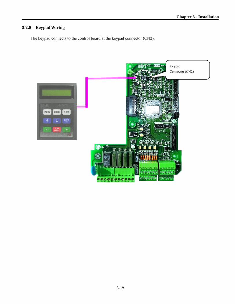
3.2.8 KeypadWiring
The keypad connects to the control board at the keypad connector (CN2).
Keypad
Connector (CN2)

3-1
Notes :

4-1
Chapter4. Operation
4.1 KeypadProgramming
4.1.1 LCDKeypad The RSi SG drive LCD keypad can display up to 32 alphanumeric characters. Drive status can be checked directly from the display and parameter values can be adjusted. The following is an illustration of the keypad.
32 character, background light, LCD display. The background tone is adjustable.
The Mode Button moves you forward through the seven parameter groups: DRV [Mode] FUN [ENT]DRV
The Up and Down Arrows are used to move through and change data.
Reverse Run Button The Reverse Run LED blinks when the drive Accels or Decels.
The Program Button is used to go into programming mode to change data.
The Enter Button is used to enter changed data within a parameter. The Enter Button also moves you reverse through the groups: DRV [ENT] APP [ENT] I/O
[SHIFT] This button is used to move cursor across display in programming mode. [ESC] This button is used to move the program code to DRV 00 from any program code.
Forward Run Button The Forward Run LED blinks when the drive Accels or Decels.
Stop Button is used to stop the drive from running and is always active regardless of control settings. Reset Button is used to reset Faults. LED blinks when there is a fault.

Chapter 4 - Operation
4-2
4.1.2 DetailedDescription LCD Keypad Display
D R V T / K 0 . 0 A0 0 S T P 0 . 0 0 H z
Displays Description
1) Parameter Group Displays the parameter group. There are DRV, FUN, AFN, I/O, and APP groups.
2) Run/Stop Source
Displays the control source for the drives run command.
K: Run/Stop using FWD, REV buttons on keypad
T: Run/Stop using control terminal input FX, RX
R: Run/Stop using Modbus
O: Run/Stop via option board
3) Frequency Setting
Source
Displays the source of the drive's frequency command.
K: Frequency setting using keypad
V: Frequency setting using V1 (0 ~12V) or V1 + I terminal
W: Frequency setting using V1S (-12~ 12V)
I: Frequency setting using I (4 ~ 20mA) terminal
P: Frequency setting using Pulse input
R: Frequency setting using RS-485, Modbus-RTU
U: Up terminal input when Up/Down operation is selected
D: Down terminal input when Up/Down operation is selected
S: Stop status when Up/Down operation is selected
O: Frequency setting via Communication Option board
J: Jog terminal input
1 ~ 15: Step frequency operation (except Jog)
4) Output Current Displays the Output Current during operation.
5) Parameter Number Displays the parameter number. Use the ▲(Up), ▼(Down) key to move through the parameters.
6) Operating Status
Displays the operation information.
STP: Stop Status
FWD: During Forward operation
REV: During Reverse operation
DCB: During DC Braking
LOV: Loss of Analog Frequency Reference (V1: 0~12V, -12~12V)
LOI: Loss of Analog Frequency Reference (I: 4~20mA)
LOA: Loss of Pulsed Reference Input
LOR: Loss of Reference from Communications Option Board (Communication network fault)
Over Lap (flashing): More than one digital input is programmed to the same function.
7) Drive Output Frequency/
Command Frequency
Displays the Output Frequency during run.
Displays the Command Frequency during stop.
►
2) Run/Stop Source 3) Frequency Setting Source
4) Output Current
7) Drive Output Frequency During Run, Command Frequency During Stop 6) Operating Status
5) Parameter Number
1) Parameter group

Chapter 4 - Operation
4-3
4.1.3 ParameterSettingandAdjustment
1) Press [MODE] key until the desired parameter group is displayed.
2) Press [▲] or [▼] keys to move to the desired parameter number. If you know the desired parameter number, you can program the parameter number within each parameter group in “Jump code”, except DRV group.
3) Press [PROG] key to go into the programming mode, the cursor starts blinking.
4) Press [SHIFT/ESC] key to move the cursor to the desired digit.
5) Press [▲] or [▼] keys to change the data.
6) Press [ENTER] key to enter the data. The cursor stops blinking.
Note: Certain parameters cannot be changed when the drive is running or AFN-94 [Parameter Lock] is activated. (Refer to the parameter list, Chapter 5 for details). EX) Changing Accel time from 10 sec to 15 sec 1) LCD keypad Move to the desired parameter to change.
Press the [PROG] key.
A Cursor (■) will appear.
Use the [SHIFT] key to move the cursor. Change the data using [▲], [▼] keys.
Press the [ENTER] key to save the value into memory.
The Cursor will disappear.
DRV► Acc. Time 01 _10.0 sec
DRV► Acc. Time
01 █10.0 sec
DRV► Acc. Time 01 _15.0 sec
DRV► Acc. Time 01 _10.0 sec
DRV► Acc. Time 01 _15.0 sec
Chapter 4 - Operation
4-4
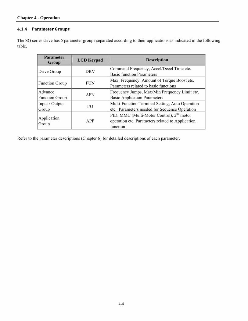
4.1.4 ParameterGroups The SG series drive has 5 parameter groups separated according to their applications as indicated in the following table.
Parameter Group LCD Keypad Description
Drive Group DRV Command Frequency, Accel/Decel Time etc. Basic function Parameters
Function Group FUN Max. Frequency, Amount of Torque Boost etc. Parameters related to basic functions
Advance Function Group
AFN Frequency Jumps, Max/Min Frequency Limit etc. Basic Application Parameters
Input / Output Group
I/O Multi-Function Terminal Setting, Auto Operation etc. Parameters needed for Sequence Operation
Application Group
APP PID, MMC (Multi-Motor Control), 2nd motor operation etc. Parameters related to Application function
Refer to the parameter descriptions (Chapter 6) for detailed descriptions of each parameter.

Chapter 4 - Operation
4-5
Parameter Navigation: Pressing the [SHIFT] key at any time moves directly to the main screen of the DRV group. Pressing the [MODE] key moves forward through the groups. Pressing the [ENTER] key moves reverse through the groups.
Drive Group FUN Group AFN Group I/O Group
Note: Actual parameters may vary due to software versions.
DRV►T/K 0.0 A 00 STP 60.00Hz
FUN► Jump code 00 1
AFN► Jump code 00 30
MODE
◄
FUN►Run prohibit 03 None
AFN► Last trip-1 01 -------
I/O► V1 filter 01 10 ms
DRV► Dec. time 02 20.0 sec
FUN►Acc. pattern 05 Linear
AFN► Last trip-2 02 -------
I/O► V1 volt x1 02 0.00 V
FUN►Dec. pattern 06 Linear
AFN► Last trip-3 03 -------
I/O► V1 freq y1 03 0.00 Hz
DRV► Freq mode 04 KeyPad-1
FUN► Stop mode 07 Decel
AFN► Last trip-4 04 -------
I/O► V1 volt x2 04 10.00 V
DRV► Rated Motor 05 Current
FUN► DcSt value 08 50 %
AFN► Last trip-5 05 -------
I/O► V1 freq y2 05 60.00 Hz
FUN► Stall Level 60 150 %
AFN► Para. lock 94 0
I/O► S0 mode 70 Frequency
MODE MODE MODE
MODE
I/O► Jump code 00 1
►
MODE
◄ ►
MODE
◄ ►
MODE
◄ ►
MODE
◄ ► ◄ ► ◄ ► ◄ ►
◄ ► ◄ ► ◄ ► ◄ ►
◄ ► ◄ ► ◄ ► ◄ ►
◄ ► ◄ ► ◄ ► ◄ ►
◄ ► ◄ ► ◄ ►
DRV► Drive mode 03 Fx/Rx-1
DRV► Fault 12 -------
DRV► Acc. time 01 10.0 sec
MODE MODE MODE
MODE MODE MODE MODE
MODE MODE MODE MODE
MODE MODE MODE MODE
MODE MODE MODE MODE
◄ ►

Chapter 4 - Operation
4-6
4.1.5 EasyStartOperation Easy Start Operation is activated by pressing STOP key on the Keypad for 2~3 seconds and the drive begins operation via Keypad (FWD/REV RUN/STOP). Drive mode is preset to V/F and reference frequency to JOG (default 10 Hz.). To exit Easy Start, press the Shift/Esc key.
4.1.6 Quickstart1:Start/StopandSpeedControlviatheKeypad
To operate the drive from the keypad, set the following parameters: DRV-03 [Drive Mode (Run/Stop method)] = 0 (Keypad) DRV-04 [Frequency Mode (Freq. setting method)] = 0 (Keypad-1)
1) Check the LCD display when power is applied. The display should read: 2) Push the PROGRAM key. 3) Enter the desired frequency by using the arrow keys. 4) Press the ENTER key to store the value into memory.
5) Press the FWD key to start the drive in the forward direction. The output frequency and output current are displayed. 6) Press the STOP/RESET key. The motor will decelerate to a stop. The set frequency will be displayed.
DRV>K/K 0.0 A00 STP 0.00Hz

Chapter 4 - Operation
4-7
4.1.7 Quickstart2:TwoWireStartandControlviaSpeedPotentiometer
Description: The following example shows how to configure the drive to operate from a speed potentiometer and a remote two wire start command. If a three-wire start/stop circuit is required refer to I/O 20 – 29. One of the inputs can be configured to 3-wire.
[Wiring]
R
S
T
G
U
V
W
M8(RX)M7(FX)M6M5M4M3M2M1CM
V+V15G (CM on Units 50 HP and larger. )
S1
5G
3A3C3B
IM3PAC
INPUT
Potentiometer2[kohm],1/2W
S/W S0
Step Parameter Name Parameter Number
Description
1 Drive Mode DRV-03 Set it to Fx/Rx-1.
2 Frequency Mode DRV-04 Set it to V1 Analog input.
3 Freq. command
setting DRV-00
Set the frequency command to desired speed via the potentiometer.
By closing M7 – CM the drive will start in the forward direction. By closing M8 – CM the drive will start in the reverse direction.
Potentiometer 1K ~ 10 K, ½ W

Chapter 4 - Operation
4-8
(CM on Units 50 HP and larger)
4.1.8 Quickstart3:TwoWireStartandControlvia4‐20mAAnalogInput
By closing M7 – CM the drive will start in the forward direction. By closing M8 – CM the drive will start in the reverse direction.
Description: The following example shows how to configure the drive to operate from a 4-20mA analog input and a remote two wire start command. If a three-wire start/stop circuit is required refer to I/O 20 – 29. One of the inputs can be configured to 3-wire.
[Wiring]
R
S
T
G
U
V
W
M8(RX)M7(FX)M6M5M4M3M2M1CM
I5G
S1
5G
3A3C3B
IM3PAC
INPUT
4 – 20mA Input
S/W S0
I
Step Parameter Name Parameter Number
Description
1 Drive Mode DRV-03 Set it to Fx/Rx-1. 2 Frequency Mode DRV-04 Set it to I Analog input.
3 Freq. command
setting DRV-00
Set the frequency command to desired speed via the analog input.

Notes :


5-1
Chapter5. ParameterList
5.1 DRV(DriveGroup)ParameterList[DRV Group]
PARAM Description LCD Keypad
Display Setting RangeFactory Default
Adj. During
Run Page
DRV-00 (Notes 1 & 2)
Main Display DRV>K/K 0.0 A
00 STP 0.50Hz.
0 - (FUN-30) Hz.
0 Yes 6-1
DRV-01 Acceleration Time 7.5~125HP Acc. time 0 - 6000 secs. 20
Yes 6-1 150~700HP Acc. time 0 - 6000 secs. 60
DRV-02 Deceleration Time
7.5~125HP Dec. time 0 - 6000 secs. 30
Yes 6-1 150~700HP Dec. time 0 - 6000 secs. 90
DRV-03 Drive Mode
(Run/Stop Method) Drive mode
Keypad Fx/Rx-1 Fx/Rx-2 Int. 485
Fx/Rx-1 No
6-1
DRV-04 Frequency Mode (Frequency
setting method) Freq mode
Keypad-1 Keypad-2
V1 V1S
I V1+I Pulse
Int. 485 Ext. PID
Keypad-1
No 6-2
DRV-05 Rated Motor Current Rated-Curr 1.0 - 999.9 Amps
Model Dependent
No 6-2
DRV-06 Electronic Thermal Selection ETH select No, Yes Yes Yes 6-3
DRV-07 Electronic Thermal Level for 1
Minute ETH 1 min DRV-08 -
200% 130 Yes 6-3
DRV-08 Electronic Thermal Level
Continuous ETH cont 50 - DRV-07 % 100 Yes 6-3
DRV-09 Characteristic Selection
(Motor Type) Motor type Self-cool
Forced-cool Self-cool Yes 6-3
DRV-10 Output Current Current Amps Amps View Only 6-4 DRV-11 DC Link Voltage DC link Vtg Volts Volts View Only 6-4
DRV-12 User Display Selection User disp Voltage kiloWatts
Volts View Only 6-4
DRV-13 Present Trip Display Fault None View Only 6-4 DRV-14 Motor Speed Speed rpm rpm View Only 6-5
DRV-15 Target/Output
Frequency Display TAR 0.00 Hz OUT 0.00 Hz Hz., RPM Hz. View Only 6-5
DRV-16 (Note 3)
Reference/Feedback Frequency Display
REF 0.00 Hz FBK 0.00 Hz Hz., RPM Hz. View Only 6-5
DRV-17 Hz/Rpm Display Hz/Rpm Disp Hz., RPM Hz. Yes 6-6 DRV-18 (Note 3)
PID Parameter R 0.0 Hz T 0.0 Hz F 0.0 Hz O 0.0 Hz Hz. View Only 6-6
DRV-19 AD Parameter V1 0 V2 0 V1S 0 I 0 View Only 6-6
DRV-20 (Note 4)
EXT-PID Parameter R 0.00% O 0.00% F 0.00% DRV 20 View Only 6-6
DRV-21 (Note 5)
Step Frequency 1 Step Freq-1 0 - (FUN-30)
Hz.
10 Yes 6-6 DRV-22 Step Frequency 2 Step Freq-2 20 Yes
DRV-23 Step Frequency 3 Step Freq-3 30 Yes

Chapter 5 – Parameter List
5-2
PARAM Description LCD Keypad
Display Setting RangeFactory Default
Adj. During
Run Page
DRV-24 Output Current Ia= 0A Ib= 0A
Ic= 0A It = 0A View Only 6-7
DRV-26 Keypad Reference Mode KeyRefMode
Minimum
Spd
Last Spd
Preset Spd 1
Stop
Fault
Disable
Disable Yes 6-7
DRV-27 Current, Phase U Ia Current, 0.0A View Only 6-7
DRV-28 Current, Phase V Ib Current, 0.0A View Only 6-7
DRV-29 Current, Phase W Ic Current, 0.0A View Only 6-7
DRV-30 Current, Ground Ground Curr, 0.0A View Only 6-7
DRV-91 (Note 6)
Drive Mode 2 (Run/Stop Method)
Drive mode 2 Keypad Fx/Rx-1 Fx//Rx-2
Fx/Rx-1
No 6-7
DRV-92 Frequency Mode 2 (Frequency
Setting Method) Freq mode 2
Keypad-1 Keypad-2
V1 V1S
I V1+I Pulse
Int. 485 Ext. PID
Keypad-1 No 6-7
The gray-highlighted parameters are hidden parameters and will only appear when the related functions are set.
Note 1: To change display from Hz. To RPM, see DRV 17.
Note 2: When operating in PI Mode (APP02 set to “yes”), the Set point will be displayed when stopped. The units
of the set point are selected using I/O-86. When running, speed is displayed in Hz.
Note 3: Only displayed when APP-02 is set to “yes” (PI Mode).
Note 4: Only displayed when APP-80 is set to “yes” (Ext. Process PI Mode).
Note 5: DRV21 - 23 are only displayed when I/O 20 - 27 are set to “Speed-L, -M, -H”.
Note 6: DRV91, 92 are only displayed when I/O 20 - 27 is set to “LOC/REM”.
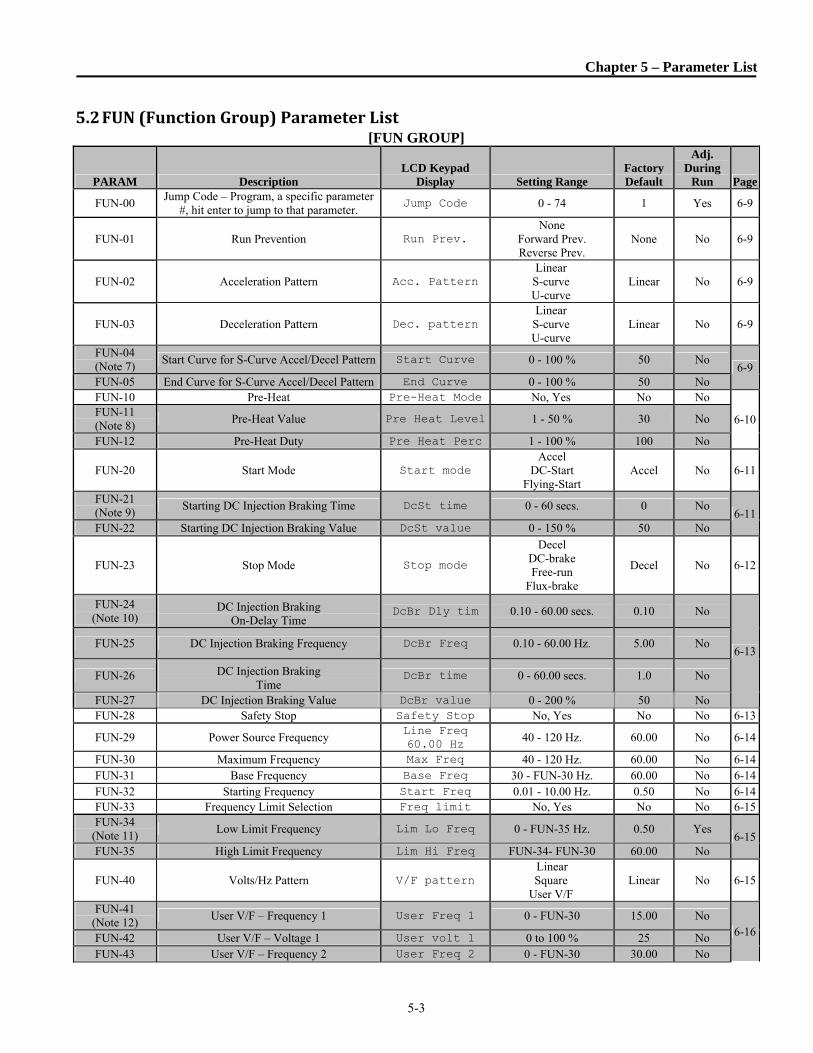
Chapter 5 – Parameter List
5-3
5.2 FUN(FunctionGroup)ParameterList[FUN GROUP]
PARAM Description LCD Keypad
Display Setting Range Factory Default
Adj. During
Run Page
FUN-00 Jump Code – Program, a specific parameter
#, hit enter to jump to that parameter. Jump Code 0 - 74 1 Yes 6-9
FUN-01 Run Prevention Run Prev. None
Forward Prev. Reverse Prev.
None No 6-9
FUN-02 Acceleration Pattern Acc. Pattern Linear
S-curve U-curve
Linear No 6-9
FUN-03 Deceleration Pattern Dec. pattern Linear
S-curve U-curve
Linear No 6-9
FUN-04 (Note 7)
Start Curve for S-Curve Accel/Decel Pattern Start Curve 0 - 100 % 50 No 6-9
FUN-05 End Curve for S-Curve Accel/Decel Pattern End Curve 0 - 100 % 50 No FUN-10 Pre-Heat Pre-Heat Mode No, Yes No No
6-10FUN-11 (Note 8)
Pre-Heat Value Pre Heat Level 1 - 50 % 30 No
FUN-12 Pre-Heat Duty Pre Heat Perc 1 - 100 % 100 No
FUN-20 Start Mode Start mode Accel
DC-Start Flying-Start
Accel No 6-11
FUN-21 (Note 9)
Starting DC Injection Braking Time DcSt time 0 - 60 secs. 0 No 6-11
FUN-22 Starting DC Injection Braking Value DcSt value 0 - 150 % 50 No
FUN-23 Stop Mode Stop mode
Decel DC-brake Free-run
Flux-brake
Decel No 6-12
FUN-24 (Note 10)
DC Injection Braking On-Delay Time
DcBr Dly tim 0.10 - 60.00 secs. 0.10 No
6-13FUN-25 DC Injection Braking Frequency DcBr Freq 0.10 - 60.00 Hz. 5.00 No
FUN-26 DC Injection Braking Time
DcBr time 0 - 60.00 secs. 1.0 No
FUN-27 DC Injection Braking Value DcBr value 0 - 200 % 50 No FUN-28 Safety Stop Safety Stop No, Yes No No 6-13
FUN-29 Power Source Frequency Line Freq 60.00 Hz 40 - 120 Hz. 60.00 No 6-14
FUN-30 Maximum Frequency Max Freq 40 - 120 Hz. 60.00 No 6-14FUN-31 Base Frequency Base Freq 30 - FUN-30 Hz. 60.00 No 6-14FUN-32 Starting Frequency Start Freq 0.01 - 10.00 Hz. 0.50 No 6-14FUN-33 Frequency Limit Selection Freq limit No, Yes No No 6-15FUN-34
(Note 11) Low Limit Frequency Lim Lo Freq 0 - FUN-35 Hz. 0.50 Yes
6-15FUN-35 High Limit Frequency Lim Hi Freq FUN-34- FUN-30 60.00 No
FUN-40 Volts/Hz Pattern V/F pattern Linear Square
User V/F Linear No 6-15
FUN-41 (Note 12)
User V/F – Frequency 1 User Freq 1 0 - FUN-30 15.00 No 6-16FUN-42 User V/F – Voltage 1 User volt 1 0 to 100 % 25 No
FUN-43 User V/F – Frequency 2 User Freq 2 0 - FUN-30 30.00 No

Chapter 5 – Parameter List
5-4
PARAM Description LCD Keypad
Display Setting Range Factory Default
Adj. During
Run PageFUN-44 User V/F – Voltage 2 User volt 2 0 - 100 % 50 No FUN-45 User V/F – Frequency 3 User Freq 3 0 - FUN-30 45.00 No
6-16FUN-46 User V/F – Voltage 3 User volt 3 0 - 100 % 75 No FUN-47 User V/F – Frequency 4 User Freq 4 0 - FUN-30 60.00 No FUN-48 User V/F – Voltage 4 User volt 4 0 - 100 % 100 No FUN-49 AC Input voltage Adjustment 100 % 73 - 115 % 100 No 6-16
FUN-50 Motor Rated Voltage (Model Dependant)
Motor Volt 0 - 600 V 230 V 460 V 575 V
No 6-16
FUN-51 Energy Save Energy save None
Manual Auto
None No 6-17
FUN-52 (Note 13)
ManualSave % Manual save% 0 - 30 % 0 Yes
FUN-54 Integrating Watt Meter KiloWattHour 0M 0.0kWh 9999999.9 kWh 0 View Only 6-17
FUN-55 Inverter Temperature Inv. Temp. 0 - 160 deg. Cel. View Only 6-17FUN-56 Motor Temperature Motor Temp. 0 - 160 deg. Cel. View Only 6-18FUN-57 No Motor Selection No Motor Sel No, Yes No No 6-18FUN-58
(Note 14) Trip Current Level No Motor Level 5 - 100 % 5 No 6-18
FUN-59 Trip Time Setting No Motor Time 0.5 - 10.0 secs. 3.0 No 6-18FUN-64 Overload Warning Level OL level 30 - 110 % 110 Yes 6-18FUN-65 Overload Warning Time OL time 0 - 30 secs. 10.0 Yes 6-18FUN-66 Overload Trip Selection OLT select No, Yes No Yes 6-19FUN-67
(Note 15) Overload Trip Level OLT level 30 - 150 % 120 Yes 6-19
FUN-68 Overload Trip Delay Time OLT time 0 - 60 secs. 60.0 Yes 6-19FUN-69 Input/Output Phase Loss Protection Trip select 000 - 111 Bit Set 001 Yes 6-19FUN-70 Stall Prevention Mode Selection Stall Mode No, Yes No No 6-20FUN-71
(Note 16) Stall Prevention Level Stall level 30 - 200 % 100 No 6-20
FUN-72 Accel/Decel Change Frequency Acc/Dec ch F 0 - FUN-30 Hz. 0 No 6-21FUN-73 Reference Frequency for Accel and Decel Acc/Dec Freq Max, Delta Max No 6-21
FUN-74 Accel/Decel Time Scale Time scale 0.01 secs. 0.1 secs.
1 sec. 0.1 Yes 6-22
FUN-75 Up/Down Save Mode UpDnSaveMode No, Yes No No 6-22
FUN-76 (Note 17)
Up?Down Save Frequency UpDnSaveFreq 0.00 – FUN-30 0 View Only 6-22
FUN-80 (Note 18)
Over Heat Warning Level OH Warn Levl 0 – 100% 90% Yes 6-22
FUN-81 (Note 16)
Analog Stall Source AnaStall Src
None I
V1 Pulse
None No 6-23
FUN-82 Current Limit Level Max Ana Perc 30 – 200% 100 No 6-23
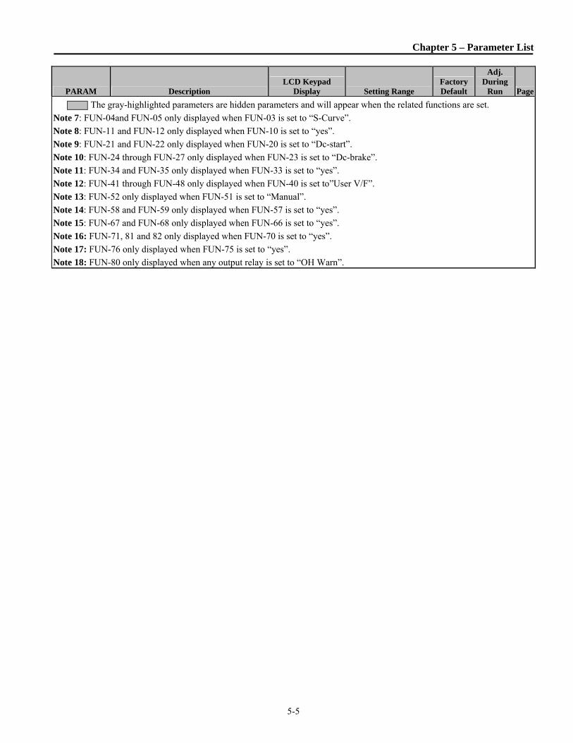
Chapter 5 – Parameter List
5-5
PARAM Description LCD Keypad
Display Setting Range Factory Default
Adj. During
Run Page
The gray-highlighted parameters are hidden parameters and will appear when the related functions are set.
Note 7: FUN-04and FUN-05 only displayed when FUN-03 is set to “S-Curve”.
Note 8: FUN-11 and FUN-12 only displayed when FUN-10 is set to “yes”.
Note 9: FUN-21 and FUN-22 only displayed when FUN-20 is set to “Dc-start”.
Note 10: FUN-24 through FUN-27 only displayed when FUN-23 is set to “Dc-brake”.
Note 11: FUN-34 and FUN-35 only displayed when FUN-33 is set to “yes”.
Note 12: FUN-41 through FUN-48 only displayed when FUN-40 is set to”User V/F”.
Note 13: FUN-52 only displayed when FUN-51 is set to “Manual”.
Note 14: FUN-58 and FUN-59 only displayed when FUN-57 is set to “yes”.
Note 15: FUN-67 and FUN-68 only displayed when FUN-66 is set to “yes”.
Note 16: FUN-71, 81 and 82 only displayed when FUN-70 is set to “yes”.
Note 17: FUN-76 only displayed when FUN-75 is set to “yes”.
Note 18: FUN-80 only displayed when any output relay is set to “OH Warn”.

Chapter 5 – Parameter List
5-6
5.3 AFN(AdvancedFunctionGroup)ParameterList[AFN GROUP]
PARAM Description
LCD Keypad
Display Setting Range
Factory
Default
Adj.
During
Run Page
AFN-00
Jump Code – Program
specific parameter #, hit
enter to jump to that
parameter.
Jump code 1 - 95 40 Yes 6-25
AFN-01 Last trip 1 Last trip-1 By pressing [PROG]
and [▲] key, the
frequency, current,
and operational status
at the time of fault can
be seen.
None View Only 6-25
AFN-02 Last trip 2 Last trip-2 None View Only 6-25
AFN-03 Last trip 3 Last trip-3 None View Only 6-25
AFN-04 Last trip 4 Last trip-4 None View Only 6-25
AFN-05 Last trip 5 Last trip-5 None View Only 6-25
AFN-06 Erase trips Erase trips No,Yes No Yes 6-25
AFN-07 Dwell Time Dwell time 0 - 10 secs. 0.0 No 6-25
AFN-08
(Note 19) Dwell Frequency Dwell freq
FUN-32 - FUN-30
Hz. 5 No 6-25
AFN-10 Frequency Jump Selection Jump freq No, Yes No No 6-26
AFN-11
(Note 20) Jump Frequency 1 Low jump Lo1 Fre 0 - AFN-12 Hz. 10 Yes
6-26
AFN-12 Jump Frequency 1 High jump Hi1 Fre AFN-11- FUN-30 Hz. 15 Yes
AFN-13 Jump Frequency 2 Low jump Lo2 Fre 0 - AFN-14 Hz. 20 Yes
AFN-14 Jump Frequency 2 High jump Hi2 Fre AFN-13- FUN-30 Hz. 25 Yes
AFN-15 Jump Frequency 3 Low jump Lo3 Fre 0 - AFN-16 Hz. 30 Yes
AFN-16 Jump Frequency 3 High jump Hi3 Fre AFN-15- FUN-30 Hz. 35 Yes
AFN-20 Power ON Start Selection Power-on run No,Yes No Yes 6-27
AFN-21 Restart after Fault Reset RST restart No, Yes No Yes
AFN-22 Instantaneous Power Failure
(IPF) restart IPF Mode No, Yes No No 6-28
AFN-23 Speed Search Estimated SS Fixed Estimated
SS View Only 6-28
AFN-24 Auto Fault Reset Retry Mode No, Yes No Yes 6-28
AFN-25
(Note 21) Number of Auto Retry Retry number 0 - 10 0 Yes 6-28
AFN-26 Delay Time
Before Auto Retry Retry delay 0 - 60 secs. 1 Yes 6-28
AFN-27 Flying Percentage Flying Perc 50 – 160% 70% No 6-29

Chapter 5 – Parameter List
5-7
PARAM Description
LCD Keypad
Display Setting Range
Factory
Default
Adj.
During
Run Page
AFN-40
Rated Motor Selection Motor select 7.5HP ~ 700HP
*
Depending
on the
inverter
capacity
No 6-29
* A motor rating same as inverter capacity is automatically set. If different, set the correct value.
AFN-41 Number of Motor Poles Pole number 2 - 12 4 No 6-29
AFN-42 Rated Motor Slip Slip Freq 0 - 10 Hz. *
Depending
on AFN-40
No 6-29
AFN-44 No Load Motor
Current(RMS) Noload-Curr 0.5 - 999.9 A No
6-29 AFN-45 Motor Efficiency Efficiency 70 - 100 % No
AFN-46 Load Inertia Inertia rate 1 - 40 10 No
AFN-47 Gain for Motor Speed
Display RPM factor 1 - 1000 % 100 Yes 6-30
AFN-48 Carrier Frequency Carrier freq
7.5 ~ 30 HP0.7~15
kHz 5 kHz
Yes
6-31
40 HP 0.7~10
kHz Yes
50 ~ 100
HP
0.7~4
kHz 4 kHz Yes
125 ~ 400
HP
0.7~3
kHz 3 kHz Yes
500 ~ 700
HP
0.7~2
kHz 2 kHz Yes
AFN-49
PWM Type Selection
PWM select
Normal
Low Leakage Low-Leakage No 6-31
AFN-52
(Note 22)
Decel Rate
(Safety Stop) Dec Rate 1 – 100 secs. 100 Yes 6-31
AFN-53 Safety Percentage Safety_perc 2 – 500 % 21 Yes 6-31
AFN-60 Control Mode Selection Control mode
V/F
V/F No 6-32 Slip Compensation
Sensorless
AFN-61 Auto Tuning Selection Auto tuning No, Yes No No
6-33 AFN-62 Stator Resistance of Motor Rs
0 - (depending on
AFN-40) ohm *
Depending
on AFN-40
No
AFN-63 Leakage Inductance of Motor Lsigma 0 - (depending on
AFN-40) mH No
AFN-64
(Note 23) Pre-excitation Time PreEx time 0 - 60 secs. 1 No 6-34

Chapter 5 – Parameter List
5-8
PARAM Description
LCD Keypad
Display Setting Range
Factory
Default
Adj.
During
Run Page
AFN-65 P Gain for
Sensorless Control SL P-gain 0 - 9999 3000 Yes 6-34
AFN-66 I Gain for Sensorless Control SL I-gain 0 - 9999 1000 Yes 6-34
AFN-67 Manual/Auto Torque Boost
Selection Torque boost
Manual Manual No 6-35
Auto
AFN-68 Torque Boost in
Forward Direction Fwd boost 0 - 15 % 2 No
6-35
AFN-69 Torque Boost in
Reverse Direction Rev boost 0 - 15 % 2 No
AFN-80 Power On display PowerOn disp 0 - 12 0 Yes 6-36
AFN-81 User Display Selection User disp Voltage
Voltage Yes 6-36 Watt
AFN-82 Software Version iP5A Benshaw Ver 1.0 Ver X.XX View Only 6-36 AFN-83 Last Trip Time LastTripTime X:XX:XX:XX:XX:X View Only
6-36 AFN-84 Power On Time On-time X:XX:XX:XX:XX:X View Only
AFN-85 Run-time Run-time X:XX:XX:XX:XX:X View Only
AFN-87 Power Display Adjustment Power Set 0.1 - 400 % 100 Yes
AFN-90 Parameter Display Para. disp
Default
Default No 6-37 All Para
Diff Para
AFN-91 Read Parameter Para. Read No
No No 6-37 Yes
AFN-92 Write Parameter Para. Write No
No No 6-37 Yes
AFN-93 Initialize Parameters Para. init
No
No No 6-38
All Groups
DRV
FUN
AFN
I/O
EXT
COM
APP
AFN-94 Parameter Write Protection Para. Lock 0 - 9999 0 Yes 6-38
AFN-95 Parameter Save Para. save No
No No 6-38 Yes
AFN-96 Password Register PW Register 0001-9999 0 Yes 6-38
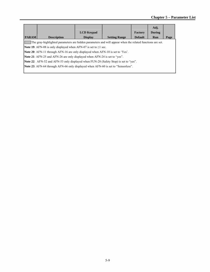
Chapter 5 – Parameter List
5-9
PARAM Description
LCD Keypad
Display Setting Range
Factory
Default
Adj.
During
Run Page
The gray-highlighted parameters are hidden parameters and will appear when the related functions are set.
Note 19: AFN-08 is only displayed when AFN-07 is set to ≥1 sec.
Note 20: AFN-11 through AFN-16 are only displayed when AFN-10 is set to ‘Yes’.
Note 21: AFN-25 and AFN-26 are only displayed when AFN-24 is set to “yes”.
Note 22: AFN-52 and AFN-53 only displayed when FUN-28 (Safety Stop) is set to “yes”.
Note 23: AFN-64 through AFN-66 only displayed when AFN-60 is set to “Sensorless”.

Chapter 5 – Parameter List
5-10
5.4 I/O(Input/OutputGroup)ParameterList[I/O GROUP]
PARAM Description LCD Keypad
Display Setting Range Factory Default
Adj. During
Run Page
I/O-00
Jump Code – Program a
specific parameter #, hit
enter to jump to that
parameter
Jump code 1 - 98 1 Yes 6-39
I/O-01
(Note 24)
Filtering Time Constant for
V1 Signal Input V1 filter 0 - 9999 msec 10 Yes
6-39
I/O-02 V1 Input Minimum Voltage V1 volt x1 0 – I/O-04 V 0 Yes
I/O-03 Frequency Corresponding to
V1 Input Minimum Voltage V1 freq y1 0 - FUN-30 Hz 0 Yes
I/O-04 V1 Input Maximum Voltage V1 volt x2 0 – 12 V 10 Yes
I/O-05 Frequency Corresponding to
V1 Input Maximum Voltage V1 freq y2 0 - FUN-30 Hz 60 Yes
I/O-06 Filtering Time Constant for I
Signal Input I filter 0 - 9999 msec 10 Yes
6-40
I/O-07 I Input Minimum Current I curr x1 0 - I/O-09 mA 4 Yes
I/O-08 Frequency Corresponding to
I Input Minimum Current I freq y1 0 - FUN-30 Hz 0 Yes
I/O-09 I Input Maximum Current I curr x2 0 - 20 mA 20 Yes
I/O-10 Frequency Corresponding to
I Input Maximum Current I freq y2 0 - FUN-30 Hz 60 Yes
I/O-11 Pulse input method P pulse set A A Yes
6-41
I/O-12 Pulse input filter P filter 0 - 9999 msec 10 Yes
I/O-13 Pulse input Minimum
frequency P pulse x1 0 - 10 kHz 0 Yes
I/O-14
Frequency corresponding to
I/O-13 Pulse input Minimum
frequency
P freq y1 0 - FUN-30 Hz 0 Yes
I/O-15 Pulse Input Maximum
Frequency P pulse x2 0 - 100 kHz 10 Yes
I/O-16
Frequency corresponding to
I/O-15 Pulse input Maximum
frequency
P freq y2 0 - FUN-30 Hz 60 Yes
I/O-17 Criteria for Analog Input
Signal Loss Wire broken
None
half of x1
below x1
None Yes 6-42

Chapter 5 – Parameter List
5-11
PARAM Description LCD Keypad
Display Setting Range Factory Default
Adj. During
Run Page
I/O-18 Operating selection at Loss
of Freq. Reference Lost command
None
Free Run
Stop
Protection
None Yes
6-42
I/O-19 Waiting Time after Loss of
Freq. Reference Time out 0.1 - 120 sec 1.0 Yes
I/O-20 Multi-Function Input
Terminal ‘M1’ Define M1 define
Speed-L
Speed-M
Speed-H
XCEL-L
XCEL-M
XCEL-H
Dc-brake
2nd Func
Exchange
Reserved
UpDown
3-Wire
Ext Trip
Pre-Heat
iTerm Clear
Open-loop
LOC/REM
Analog hold
XCEL stop
P Gain2
Reserved
Interlock1
Interlock2
Interlock3
Interlock4
Speed_X
RST
BX
JOG
FX
RX
ANA_CHG
Ext PID Run
Up/Dn Clr
Speed-L Yes 6-43
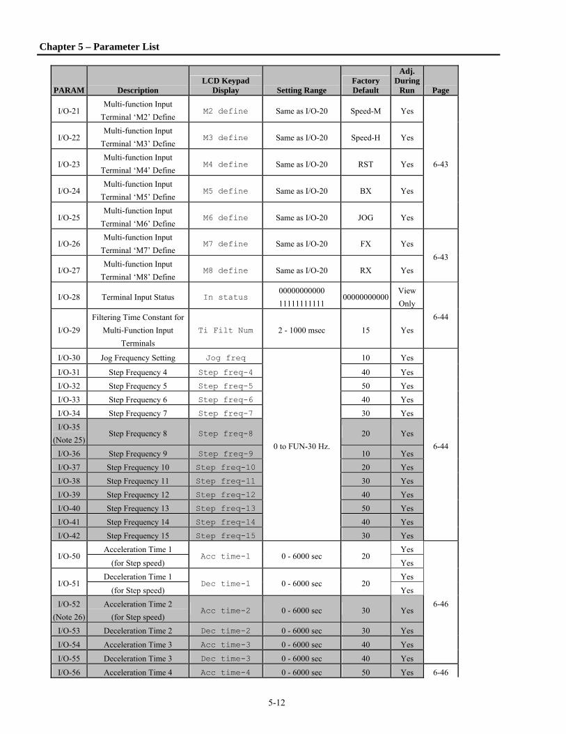
Chapter 5 – Parameter List
5-12
PARAM Description LCD Keypad
Display Setting Range Factory Default
Adj. During
Run Page
I/O-21 Multi-function Input
Terminal ‘M2’ Define M2 define Same as I/O-20 Speed-M Yes
6-43
I/O-22 Multi-function Input
Terminal ‘M3’ Define M3 define Same as I/O-20 Speed-H Yes
I/O-23 Multi-function Input
Terminal ‘M4’ Define M4 define Same as I/O-20 RST Yes
I/O-24 Multi-function Input
Terminal ‘M5’ Define M5 define Same as I/O-20 BX Yes
I/O-25 Multi-function Input
Terminal ‘M6’ Define M6 define Same as I/O-20 JOG Yes
I/O-26 Multi-function Input
Terminal ‘M7’ Define M7 define Same as I/O-20 FX Yes
6-43
I/O-27 Multi-function Input
Terminal ‘M8’ Define M8 define Same as I/O-20 RX Yes
I/O-28 Terminal Input Status In status 00000000000
11111111111 00000000000
View
Only
6-44
I/O-29
Filtering Time Constant for
Multi-Function Input
Terminals
Ti Filt Num 2 - 1000 msec 15 Yes
I/O-30 Jog Frequency Setting Jog freq
0 to FUN-30 Hz.
10 Yes
6-44
I/O-31 Step Frequency 4 Step freq-4 40 Yes
I/O-32 Step Frequency 5 Step freq-5 50 Yes
I/O-33 Step Frequency 6 Step freq-6 40 Yes
I/O-34 Step Frequency 7 Step freq-7 30 Yes
I/O-35
(Note 25) Step Frequency 8 Step freq-8 20 Yes
I/O-36 Step Frequency 9 Step freq-9 10 Yes
I/O-37 Step Frequency 10 Step freq-10 20 Yes
I/O-38 Step Frequency 11 Step freq-11 30 Yes
I/O-39 Step Frequency 12 Step freq-12 40 Yes
I/O-40 Step Frequency 13 Step freq-13 50 Yes
I/O-41 Step Frequency 14 Step freq-14 40 Yes
I/O-42 Step Frequency 15 Step freq-15 30 Yes
I/O-50 Acceleration Time 1
Acc time-1 0 - 6000 sec 20 Yes
6-46
(for Step speed) Yes
I/O-51 Deceleration Time 1
Dec time-1 0 - 6000 sec 20 Yes
(for Step speed) Yes
I/O-52
(Note 26)
Acceleration Time 2
(for Step speed) Acc time-2 0 - 6000 sec 30 Yes
I/O-53 Deceleration Time 2 Dec time-2 0 - 6000 sec 30 Yes
I/O-54 Acceleration Time 3 Acc time-3 0 - 6000 sec 40 Yes
I/O-55 Deceleration Time 3 Dec time-3 0 - 6000 sec 40 Yes
I/O-56 Acceleration Time 4 Acc time-4 0 - 6000 sec 50 Yes 6-46
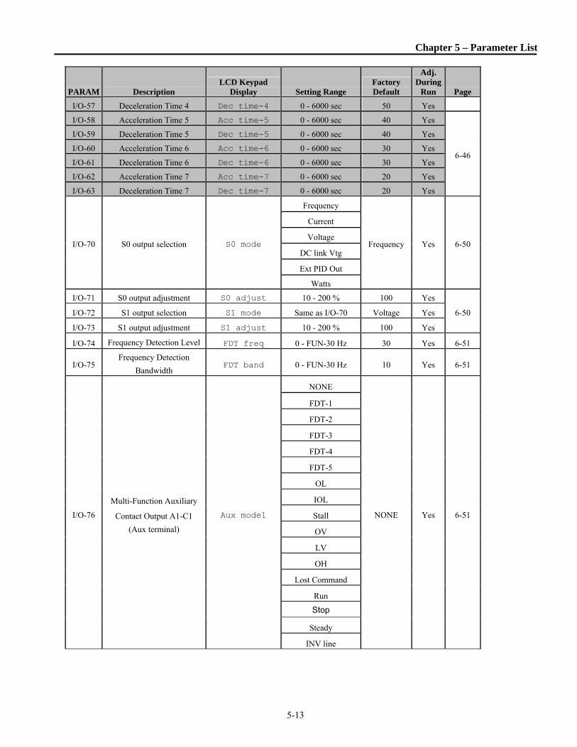
Chapter 5 – Parameter List
5-13
PARAM Description LCD Keypad
Display Setting Range Factory Default
Adj. During
Run Page
I/O-57 Deceleration Time 4 Dec time-4 0 - 6000 sec 50 Yes
I/O-58 Acceleration Time 5 Acc time-5 0 - 6000 sec 40 Yes
6-46
I/O-59 Deceleration Time 5 Dec time-5 0 - 6000 sec 40 Yes
I/O-60 Acceleration Time 6 Acc time-6 0 - 6000 sec 30 Yes
I/O-61 Deceleration Time 6 Dec time-6 0 - 6000 sec 30 Yes
I/O-62 Acceleration Time 7 Acc time-7 0 - 6000 sec 20 Yes
I/O-63 Deceleration Time 7 Dec time-7 0 - 6000 sec 20 Yes
I/O-70 S0 output selection S0 mode
Frequency
Frequency Yes 6-50
Current
Voltage
DC link Vtg
Ext PID Out
Watts
I/O-71 S0 output adjustment S0 adjust 10 - 200 % 100 Yes
6-50 I/O-72 S1 output selection S1 mode Same as I/O-70 Voltage Yes
I/O-73 S1 output adjustment S1 adjust 10 - 200 % 100 Yes
I/O-74 Frequency Detection Level FDT freq 0 - FUN-30 Hz 30 Yes 6-51
I/O-75 Frequency Detection
Bandwidth FDT band 0 - FUN-30 Hz 10 Yes 6-51
I/O-76
Multi-Function Auxiliary
Contact Output A1-C1
(Aux terminal)
Aux mode1
NONE
NONE Yes 6-51
FDT-1
FDT-2
FDT-3
FDT-4
FDT-5
OL
IOL
Stall
OV
LV
OH
Lost Command
Run
Stop
Steady
INV line

Chapter 5 – Parameter List
5-14
I/O-76
(con’t)
Multi-Function Auxiliary
Contact Output A1-C1
(con’t)
COMM line
6-51
SpeedSearch
Ready
MMC
OH Warn
FAN Signal
RMT Status
I/O-77 Multi-Function Auxiliary
Contact Output A2-C2 Aux mode2 Same as I/O-76 NONE Yes
6-51 I/O-78 Multi-Function Auxiliary
Contact Output A3-C3 Aux mode3 Same as I/O-76 NONE Yes
I/O-79 Multi-Function Auxiliary
Contact Output A4-C4 Aux mode4 Same as I/O-76 NONE Yes
I/O-80 Fault Output Relay Setting
(30A, 30B, 30C) Relay mode 000 - 111 bit 010 Yes 6-55
I/O-81 Terminal Output Status Out status 00000000
11111111 0
View
Only 6-55
I/O-82 Fault Output Relay
On Delay Time Relay On 0 - 9999 secs. 0 No
6-55
I/O-83 Fault Output Relay
Off Delay Time Relay Off 0 - 9999 secs. 0 No
I/O-84 Fan Con Sel (50 ~ 700HP) Fan Con. Sel
PowerOn_Fan
PowerOn_
Fan No 6-56 Run Fan
Temper-Fan
I/O-85 Fan Temp (50 ~ 700HP) Fan Temp 0 - 70 ℃ 70 Yes 6-56
I/O-86
(Note 27)
Analog Input
User Unit Selection Unit Sel
Speed
Percent
Bar
mBar
kPa
Pa
PSI
PSI No
6-56
I/O-87
(Note 27) Unit Maximum Value Unit Max Val 1 – 999.9
100.0
PSI No

Chapter 5 – Parameter List
5-15
PARAM Description
LCD Keypad
Display Setting Range
Factory
Default
Adj.
During
Run Page
I/O-90 Inverter Number Inv No. 1 - 250 1 Yes
6-57 I/O-91 Baud Rate Selection Baud rate
1200 bps
9600 Yes
2400 bps
4800 bps
9600 bps
19200 bps
38400 bps
I/O-92 Operating method
at loss of frequency reference COM Lost Cmd
None
None Yes 6-57 FreeRun
Stop
I/O-93 Loss of Communication
Delay Time COM Time Out 0.1 - 120 sec 1.0 Yes 6-57
I/O-94 Communication Response
Delay time Delay Time 2 - 1000 msec 5 Yes 6-57
I/O-95 A or B contact In No/Nc Set 00000000000
11111111111 0 No 6-58
I/O-96 Input time In CheckTime 1 - 1000 msec 1 No 6-58
I/0-97 Overheat trip selection OH Trip Sel 000 - 111 bit 010 No
6-58 I/0-98
Motor overheat trip
temperature MotTripTemp. 0 - 255 ℃ 110 No
The gray-highlighted parameters are hidden parameters and will appear when the related functions
are set.
Note 24: When DRV-04 and/or DRV-92 are set to either V1, V1S, I, V1+I, or Pulse only selected
parameters are displayed in I/O-01~I/O-19.
Note 25: I/O-35 ~ I/O-42 displayed only when one of I/O-20 ~ I/O-27 is set to Speed_X.
Note 26: I/O-52 ~ I/O-63 displayed only when one of I/O-20 ~ I/O-27 is set to either XCEL_L, XCEL_M,
XCEL_H.
Note 27: When Process PI Control is selected with APP-02, select units with I/O-86 and the maximum
value of the units with I/O-87. See also APP-06, APP-31, APP-32 and APP-33.

Chapter 5 – Parameter List
5-16
5.5 APP(ApplicationGroup)ParameterList[APP GROUP]
PARAM Description LCD Keypad
Display Setting Range Factory Default
Adj. During
Run Page
APP-00
Jump Code – Program a
specific parameter #, hit
enter to jump to that
parameter
Jump code 1 1 ~ 97 Yes Yes 6-61
APP-01
(Note 28)
Application Mode
Selection App mode
None
MMC None No 6-61
APP-02 PID Operation Selection Proc PI mode No, Yes No No 6-61
APP-03
(Note 29) PID F Gain Selection PID F-gain 0 - 999.9 % 0.00 Yes 6-66
APP-04 PID Auxiliary Reference
Mode Selection Aux Ref Mode
No
Yes No No 6-66
(Note 30)
APP-05
(Note 31)
PID Auxiliary Reference
Signal Selection Aux Ref Sel
Keypad-1
Keypad-2
V1
V1S
I
V1+I
Pulse
Int. 485
Ext. PID
V1 No 6-66
APP-06 PID Feedback Signal
Selection PID F/B
I
V1
Pulse
0 (I) No 6-66
APP-07 P Gain for PID Control PID P-gain 0 - 999.9 % 1.00 Yes 6-66 APP-08 I Gain for PID Control PID I-time 0 - 32.0 sec 10.0 Yes 6-66 APP-09 D Gain for PID Control PID D-time 0 -100 msec 0.0 msec Yes 6-66
APP-10 High Limit Frequency for
PID Control PID limit-H 0.00 - 300.00 Hz 60 .00 Yes 6-67
APP-11 Low Limit Frequency for
PID Control PID limit-L
Start Freq
- 300.00 Hz 0.5 Yes 6-67
APP-12 PID Output Scale PID Out Scale 0.0 - 999.9 % 100.00 No 6-67 APP-13 PID P2 Gain PID P2-gain 0.0 - 999.9 % 100.00 No 6-67 APP-14 P Gain Scale P-gain Scale 0.0 - 100.0 % 100.00 No
6-67 APP-15 PID Output Inverse Out inverse
No
Yes No No
APP-17 PID U curve feedback
select PID U Fbk
No
Yes No No
APP-20
(Note 32) 2nd Acceleration Time 2nd Acc time 0 - 6000 sec 5 Yes 6-68

Chapter 5 – Parameter List
5-17
PARAM Description LCD Keypad
Display Setting Range Factory Default
Adj. During
Run Page
APP-21 2nd Deceleration Time 2nd Dec time 0 6000 sec 10 Yes
APP-22 2nd Base Frequency 2nd BaseFreq 30 - FUN-30 Hz 60 No 6-68
APP-23 2nd V/F Pattern 2nd V/F
Linear
Square
User V/F
Linear No
6-68 APP-24 2nd Forward Torque Boost 2nd F-boost 0 - 15 % 2 No
APP-25 2nd Reverse Torque Boost 2nd R-boost 0 - 15 % 2 No
APP-26 2nd Stall Prevention Level 2nd Stall 30 - 150 % 100 No
APP-27 2nd Electronic Thermal
Level for 1 minute 2nd ETH 1min AFN-28 - 200 % 130 Yes
6-68 APP-28
2nd Electronic Thermal
Level for continuous 2nd ETH cont
50 - AFN-27
(Max. 150%) 120 Yes
APP-29 2nd Rated Motor Current 2nd R-Curr 1 - 200 A 3.6 No
APP-31
(Note 34) Meter I Max Value Meter I max 0 – 20 mA 20 Yes 6-68
APP-32
(Note 34) Meter V1 Max Value Meter V max 0 – 12 V 10V Yes 6-68
APP-33
(Note 34) Meter P Max Value Meter P max 0 – 100 kHz. 100kHz Yes 6-68
APP-40
(Note 28)
Number of Auxiliary
Motor Run Display Aux Mot Run View Only View Only
View
Only
6-69 APP-41 Aux. Motor Start Selection Starting Aux 1 - 4 1 Yes
APP-42 Operation Time Display on
Auto Change Auto Op Time View Only View Only
View
Only
APP-43 The Number of Aux Motor Nbr Aux`s 0 - 4 4 Yes
APP-44 Start Frequency of Aux.
Motor 1 Start freq 1
0 - FUN-30 Hz
49.99 Yes
6-70
APP-45 Start Frequency of Aux.
Motor 2 Start freq 2 49.99 Yes
APP-46 Start Frequency of Aux.
Motor 3 Start freq 3 49.99 Yes
APP-47 Start Frequency of Aux.
Motor 4 Start freq 4 49.99 Yes
APP-51 Stop Frequency of Aux.
Motor 1 Stop freq 1
0 - FUN-30 Hz
20.00 Yes
6-70
APP-52 Stop Frequency of Aux.
Motor 2 Stop freq 2 20.00 Yes
APP-53 Stop Frequency of Aux.
Motor 3 Stop freq 3 20.00 Yes
APP-54 Stop Frequency of Aux.
Motor 4 Stop freq 4 20.00 Yes
APP-58 Delay Time before
Operating Aux Motor Aux start DT 0.0 - 999.9 sec 5.0 Yes 6-71

Chapter 5 – Parameter List
5-18
PARAM Description LCD Keypad
Display Setting Range Factory Default
Adj. During
Run Page
APP-59 Delay Time before
Stopping Aux Motor Aux stop DT 0.0 - 999.9 sec 5.0 Yes 6-71
APP-60 Accel time when the
number of pump decreases Pid AccTime 0 - 600.0 sec 2.0 Yes 6-71
APP-61 Decel time when the
number of pump increases Pid DecTime 0 - 600.0 sec 2.0 Yes 6-71
APP-62 PID Bypass Selection Regul Bypass No
Yes No No 6-71
APP-63
(Note 29) Sleep Delay Time Sleep Delay 0.0 - 9999 sec 60.0 Yes 6-72
APP-64 Sleep Frequency Sleep Freq 0 - FUN-30 Hz 0.00 Yes 6-72
APP-65 Wake-Up Level WakeUp level 0.0 - 100.0 % 35 .00 Yes 6-72
APP-66
(Note 28)
Auto Change Mode
Selection AutoCh_Mode
0
1 (Aux)
2 (Main)
0 Yes 6-73
APP-67 Auto Change Time AutoEx-intv 00:00 - 99:00 72:00:00 Yes 6-73
APP-68 Auto Change Frequency AutoEx-Freq FUN-32 -
FUN-30 Hz 20.0 Yes 6-73
APP-69 Inter-Lock Selection Inter-lock No Yes
No Yes 6-75
APP-71
(Note 28)
Pressure difference for Aux motor Start
Aux Stt Diff 0 - 100 % 2 Yes 6-76
APP-72 Pressure difference for Aux
motor Stopt Aux Stp Diff 0 – 100% 2 Yes 6-76
APP-74
(Note 29)
PrePID Reference
Frequency PrePID freq 0 - FUN-30 Hz 0 Yes
6-76 APP-75 PrePID Exit Level PrePID Exit 0 - 100.0% 0 Yes
APP-76 PrePID Stop delay PrePID dly 0 - 9999 600 Yes
APP-77 Pipe Broken Pipe Broken No, Yes No Yes
APP-78
(Note 28)
Stopping Order of Aux
Motors
First input – Last Output
F-In L-Out Yes, No Yes No 6-77
APP-79 Stopping method of Aux
motors All-Stop Yes, No Yes No 6-77
APP-80 Ext PID Operation
Selection Ext PI mode
No
Yes No No 6-77
APP-81
(Note 33)
Ext PID Reference
Signal Selection Ext Ref Sel
I
V1
Pulse
Keypad
Keypad No 6-77
APP-82 Ext PID
Reference Level Ext Ref Perc 0 - 100.00 % 50.00 No 6-77

Chapter 5 – Parameter List
5-19
PARAM Description LCD Keypad
Display Setting Range Factory Default
Adj. During
Run Page
APP-83 Ext PID Feedback Signal
Selection Ext Fbk Sel
I
V1
Pulse
I No 6-77
APP-85 P Gain for ExtPID ExtPID Pgain 0 - 999.9 % 1.00 No 6-77
APP-86 I Time for ExtPID ExtPID Itime 0 - 32.0 sec 10.0 No 6-77
APP-87 D Time for ExtPID ExtPID Dtime 0 - 2000 msec 0 No 6-77
APP-88 High Limit Frequency for
ExtPID Control ExtPID lmt-H 0 - 100.00 100.00 No 6-77
APP-89 Low Limit Frequency for
ExtPID Control ExtPID lmt-L 0 - 30.00 % 0 No 6-77
APP-90 ExtPID Output Scale ExtPID Scale 0 - 999.9 % 100.00 No 6-77
APP-91 ExtPID P2 Gain Ext P2-gain 0 - 999.9 % 100.00 No 6-77
APP-92 ExtPID
P Gain Scale Ext P Scale 0 - 100.0 100.00 No 6-77
APP-93 ExtPID F Gain ExtPID F-gain 0 - 999.9 % 0.00 Yes 6-77
APP-95 ExtPID Output Inverse ExtOut inverseNo
Yes No No 6-77
APP-97 ExtPID Loop Time Ext Loop Time 50 - 200 msec 100 No 6-77
The gray-highlighted parameters are hidden parameters and will only appear when the related functions
are set.
Note 28: Only APP-40~APP-62, APP-66~APP-69, APP-71, 72, 78 and 79 are displayed when APP-01 is set
to “MMC”.
Note 29: Only APP-03~APP-17, APP-31~APP-33, APP-63~APP-65 and APP-74~APP-77 are displayed
when APP-02 is set to “Yes”.
Note 30: If APP-04 is set to “NO”, DRV-04 setting will be reference (set point) of process PID. And APP -05
setting will be ignored.
Note 31: If APP-04 is set to “Yes”, APP-05 will appear. And APP -05 setting value will be reference (set
point) of process PID, DRV-04 setting will be ignored.
Note 32: Only APP-20 ~ APP-29 displayed only when one of I/O-20 ~ I/O-27 is set to either “2nd Func”.
Note 33: Only APP-81 ~ APP-97 displayed when APP-80 is set to “Yes”.
Note 34: Only one of APP-31, 32 or 33 are displayed dependant on APP-06 selection (I, V1, Pulse).
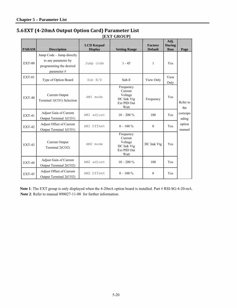
Chapter 5 – Parameter List
5-20
5.6 EXT(4‐20mAOutputOptionCard)ParameterList [EXT GROUP]
PARAM Description LCD Keypad
Display Setting Range Factory Default
Adj. During
Run Page
EXT-00
Jump Code – Jump directly
to any parameter by
programming the desired
parameter #
Jump code 1 - 45 1 Yes
Refer to
the
correspo
nding
option
manual
EXT-01
Type of Option Board Sub B/D Sub-E View Only
View
Only
EXT-40 Current Output
Terminal 1(CO1) Selection AM1 mode
Frequency Current Voltage
DC link Vtg Ext PID Out
Watt
Frequency
Yes
EXT-41 Adjust Gain of Current
Output Terminal 1(CO1) AM1 adjust 10 – 200 % 100 Yes
EXT-42 Adjust Offset of Current
Output Terminal 1(CO1) AM1 Offset 0 – 100 % 0 Yes
EXT-43 Current Output
Terminal 2(CO2) AM2 mode
Frequency Current Voltage
DC link Vtg Ext PID Out
Watt
DC link Vtg Yes
EXT-44 Adjust Gain of Current
Output Terminal 2(CO2) AM2 adjust 10 – 200 % 100 Yes
EXT-45 Adjust Offset of Current
Output Terminal 2(CO2) AM2 Offset 0 – 100 % 0 Yes
Note 1: The EXT group is only displayed when the 4-20mA option board is installed. Part # RSI-SG-4-20-mA.
Note 2: Refer to manual 890027-11-00 for further information.

Notes


6-1
Chapter6. ParameterDescriptions
6.1 DriveGroup[DRV] DRV-00: Command Frequency / Output Current
1) Digital frequency setting This parameter is used to set the command frequency when DRV-04 [Frequency Mode] is set to Keypad-1 or Keypad-2. It can be set to a value equal to or less than FUN-30 [Maximum Frequency]. 2) Monitoring function setting The command frequency is displayed during stop. Output current and frequency are displayed during run. When DRV-04 [Frequency Mode] is set to V1, V1S, I, V1+ I or Pulse the drive will display the reference frequency during stop. If PID control is active the user can change the units to be displayed in I/O-86. When DRV-17 [Speed Unit Selection] is set to Rpm, the display will show RPM rather than Hz. DRV-01, 02: Accel/Decel Time The acceleration time is the amount of time that it takes (from zero Hz.) for the drive to reach the maximum frequency set in FUN-30 when the drive receives a start command. The deceleration time is amount of time the drive takes to stop from the maximum
frequency in FUN-30 to 0Hz when a stop command is given. When FUN-73 is set to “Delta Frequency”, the acceleration and deceleration time is the time taken to reach a target frequency (instead of the maximum frequency) from a specific frequency. Note: Set the Accel time more than 0.5 sec for smooth acceleration. Setting it too short may deteriorate the starting performance. DRV-03: Drive Mode (Run/Stop Method) This parameter selects the source of run/stop command. LCD
Setting Range Description
Keypad Run/Stop control by Keypad.
Fx/Rx-1
Run/Stop control by Control
Terminals FX, RX. (Method 1)
FX: Two wire contact for forward
Run/Stop
RX: Two wire contact for reverse
Run/Stop
Fx/Rx-2
Run/Stop control by Control
Terminals FX, RX. (Method 2)
FX: Two wire for Run/Stop
command
RX: Two wire for Forward/Reverse
selection (Open-Fwd, Closed-Rev)
Int. 485 Run/Stop control by Modbus.
DRV► Acc. time 01 20.0 sec
Factory Default: 20.0 sec
DRV► Dec. time 02 30.0 sec
Factory Default: 30.0 sec
DRV► Drive mode 03 Fx/Rx-1
Factory Default: Fx/Rx-1
DRV► T/K 0.0A 00 STP 0.00 Hz
Factory Default: 0.00 Hz

Chapter 6 - Parameter Description [DRV]
6-2
DRV-04: Frequency Mode
This parameter selects the method of speed control for the drive.
LCD
Setting Range Description
Keypad-1
Frequency is set at DRV-00. The
frequency is changed by pressing PROG key and entered by pressing
ENTER key. The drive does not
output the changed frequency until the ENTER key is pressed.
Keypad-2
(EMOP)
Frequency is set at DRV-00. Press PROG key and then by pressing the
▲, ▼ key, the drive immediately
outputs the changed frequency. Pressing the ENTER key saves the
changed frequency.
V1
The drive uses V1 (0-12V) signal for
speed control. Refer to I/O-01 to I/O-
05 for scaling the signal.
V1S
The drive uses V1 (-12V to 12V) as a
bipolar input. Refer to I/O-01 to I/O-
05 for scaling the signal.
I
The drive uses I (4~20mA) signal for
speed control. Refer to I/O-06 to I/O-
10 for scaling the signal.
V1+I
The drive uses both the V1 and I
(0~12V, 4~20mA) control terminals.
The ‘V1’ signal overrides the ‘I’
signal. See I/O-01~ I/O-10.
PULSE The drive uses the “A0, B0” terminals.
Range: 0~100kHz. See I/O-11~16.
Int. 485 The drive uses Modbus
communication. See I/O-90~93.
LCD
Setting Range Description
Ext. PID
Set APP-80 [Ext PI Mode] to “Yes.” Apply Ext. PID feedback value “4~20mA” to control terminal “I”. Set one of the I/O-20~27 to [Ext PID Run]. Drive starts Ext.PID operation when the defined terminal is ON and Ext.PID output value becomes the drives command frequency. SeeAPP-80~97 for details.
DRV-05: Motor Rated Current DRV-06: Electronic Thermal (Motor i2t) Selection DRV-07: Electronic Thermal Level for 1 Minute DRV-08: Electronic Thermal Level for Continuous DRV-09: Electronic Thermal Characteristic (Motor type) selection These parameters are to provide motor OL protection without using an external OL relay. The drive calculates the temperature rise in the motor based on several parameters and determines whether or not the motor is overheated. When an ETH trip occurs the drive will fault and display E-THERMAL. The drive cannot be reset immediately after an Eth trip. A cool down period of approximately one minute is required prior to resetting the drive. This parameter sets the motor rated full load current. This value is used by the ETH function as well other functions. This value also is referenced by many other parameters. (Refer to the motor nameplate for actual value)
CAUTION The motor rated current must be set to the correct value for many of the drive’s protective and control functions to operate correctly.
DRV► Freq mode 04 Keypad-1
Factory Default: Keypad-1
DRV► Rated-Curr05 X.X A
Factory Default: Model Dependent (This value is preset according to the motor capacity set in AFN-40)
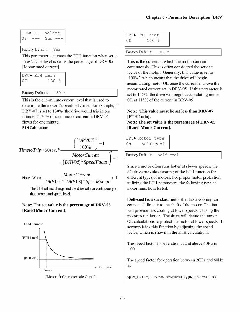
Chapter 6 - Parameter Description [DRV]
6-3
This parameter activates the ETH function when set to ‘Yes’. ETH level is set as the percentage of DRV-05 [Motor rated current]. This is the one-minute current level that is used to determine the motor I2t overload curve. For example, if DRV-07 is set to 130%, the drive would trip in one minute if 130% of rated motor current in DRV-05 flows for one minute. ETH Calculation:
Note: When 1*]08[*]05[
rSpeedFactoDRVDRV
ntMotorCurre
The ETH will not charge and the drive will run continuously at that current and speed level.
Note: The set value is the percentage of DRV-05 [Rated Motor Current].
[Motor i2t Characteristic Curve]
This is the current at which the motor can run continuously. This is often considered the service factor of the motor. Generally, this value is set to ‘100%’, which means that the drive will begin accumulating motor OL once the current is above the motor rated current set in DRV-05. If this parameter is set to 115%, the drive will begin accumulating motor OL at 115% of the current in DRV-05 Note: This value must be set less than DRV-07 [ETH 1min]. Note: The set value is the percentage of DRV-05 [Rated Motor Current]. Since a motor often runs hotter at slower speeds, the SG drive provides derating of the ETH function for different types of motors. For proper motor protection utilizing the ETH parameters, the following type of motor must be selected: [Self-cool] is a standard motor that has a cooling fan connected directly to the shaft of the motor. The fan will provide less cooling at lower speeds, causing the motor to run hotter. The drive will derate the motor OL calculations to protect the motor at lower speeds. It accomplishes this function by adjusting the speed factor, which is shown in the ETH calculations. The speed factor for operation at and above 60Hz is 1.00. The speed factor for operation between 20Hz and 60Hz is: Speed_Factor =( 0.125 %/Hz * drive frequency (Hz) + 92.5%) / 100%
DRV► ETH select 06 --- Yes ---
Factory Default: Yes
DRV► ETH 1min 07 130 %
Factory Default: 130 %
DRV► ETH cont 08 100 %
Factory Default: 100 %
DRV► Motor type 09 Self-cool
Factory Default: Self-cool
Load Current
Trip Time
[ETH 1 min]
1 minute
[ETH cont]
1*]05[
1%100
]07[
*.sec60 2
2
rSpeedFactoDRVntMotorCurre
DRV
TimetoTrip

Chapter 6 - Parameter Description [DRV]
6-4
The speed factor for operation below 20Hz is: Speed_Factor = (1.5 %/Hz * drive frequency (Hz) + 65%) / 100%
[Load Current Derating Curve] [Forced-cool] is for a motor that uses a separate motor to power a cooling fan or an inverter duty motor that does not need o be derated at lower speeds. As the motor speed changes, the cooling affect does not change. The value set in DRV-08 [Electronic thermal level for continuous] is applied regardless of operating frequency. The Speed Factor for a forced cooled motor is always 1.0. DRV-10: Output Current This parameter displays the average three-phase output current.
DRV-11 DC Link Voltage This parameter displays the DC link (DC bus) voltage.
DRV-12: User Display Selection This parameter displays the value of the parameter selected in AFN-81 [User Display]. DRV-13: Present Trip Display This parameter displays the present fault (trip) status of the drive. Use the PROG, ▲ and ▼ keys before pressing the RESET key to check the fault log content. Output frequency, output current, and the mode of operation when the fault occurred are displayed. Press the ENTER key to exit. The fault content will be stored in AFN-01 to AFN-05 after the RESET key is pressed. For more detail, refer to Chapter 7. Troubleshooting and Maintenance. [Fault Contents]
Fault (Trip) LCD
Keypad display
Over-Current 1 Over Current 1
Over-Voltage Over Voltage
External Trip Input Ext. Trip
Inverter Disable (Not Latched) BX
Low-Voltage Low Voltage
Ground Fault Ground Fault
Over-Heat on Heat sink Over Heat
Electronic Thermal Trip E-Thermal
Over-Load Trip Over Load
Inverter H/W Fault
- EEP Error - ADC Offset
- WDOG Error - In-Phase Open
HW-Diag
Over-Current 2 Over Current 2
Output Phase Loss Phase Open
Inverter Over-Load Inv. OLT
DRV► Fault 13 None
Factory Default: None
DRV► Current 10 0.0 A
Factory Default: 0.0 A
DRV► DC link vtg 11 ----- V
Factory Default: ---- V
DRV► User disp 12 0.0 V
Factory Default: 0.0 V
100%95%
65%
Output Current
20Hz 60Hz
Self-Cool
Forced-Cool

Chapter 6 - Parameter Description [DRV]
6-5
Note: Certain Hardware faults such as: WDOG error, EEP error, Input Phase Open, Fan Lock, Blown Fuse, NTC Open and ADC Offset cannot be reset until the fault condition is corrected. The drive will not reset when a H/W fault occurs. Repair the fault before turning on the power. Note: Only the highest-priority fault will be displayed when multiple faults occur. The other faults can be viewed in AFN-01~05 [Fault history]. Up to 5 faults are saved in AFN-01~05 [Fault history]. AFN-01, “Last trip-1” is the most recent fault. AFN-05, “Last trip 5” is the oldest fault. After pressing [PROG] key, press [(Up)], [(Down)] key to check the operational information at the time of the fault (Output freq., current, Accel/Decel/Constant Run) and fault type. Press the [ENTER] key to exit the fault log. AFN-06 [Erase fault history] clears the fault history. AFN-83 [Last Trip Time] is automatically set when a fault occurs. Parameter Display Description AFN-01 Last trip-1 Fault history 1 AFN-02 Last trip-2 Fault history 2 AFN-03 Last trip-3 Fault history 3 AFN-04 Last trip-4 Fault history 4 AFN-05 Last trip-5 Fault history 5
DRV-14: Motor Speed
This parameter displays the motor speed in RPM while the motor is running. It can also be displayed on the main screen, see DRV-17. Use the following equation to scale the mechanical speed using AFN-47 [Gain for Motor Speed display] if you want to change the motor speed display to rotation speed (r/min) or mechanical speed (m/min). Motor speed = 120 * (F/P) * AFN-47 Where, F= Output Frequency and P= the Number of Motor Poles
DRV-15: Target/Output Frequency Display This parameter shows the Command (Target) Frequency set in DRV-00 and the drives Output Frequency. Can also display RPM’s, see DRV-17. DRV-16: Reference/Feedback Frequency Display Appears only when ‘Yes’ is selected in APP-02 (PI Mode). This parameter shows the Reference and PI Feedback signals while in PID operation. The default units are in Hertz (Hz). The units of the Reference and PI Feedback signal (APP-06) are selected with parameter I/O-86.
Ex1) When [mBar] is set
Ex2) When [kPa] is set
DRV►TAR 0.00Hz15 OUT 0.00Hz
Factory Default: 0.00Hz
DRV►REF 0.00Hz16 FBK 0.00Hz
Factory Default: 0.00Hz
DRV►REF 500mBa16 FBK 82.1mBa
DRV►REF 500kPa 16 FBK 82.1kPa
DRV► Speed 14 0rpm
Factory Default: 0rpm

Chapter 6 - Parameter Description [DRV]
6-6
DRV-17: Hz/Rpm Display
Set this parameter to [Hz] to display frequency, or to [Rpm] to display speed on main display, DRV-00 and other parameters with units of [Hz]. DRV-18: PID Parameter (To monitor PID controller’s Reference/Feedback value and Drive’s Command/Output frequency) This parameter displays the PID controller’s reference (set point) and the feedback value on the left side of the display. It also displays the drive’s commanded and output frequency. All values are displayed in Hz (default), the feedback value will be displayed in percent [%] unit. DRV-19: AD Parameter (To monitor the AD conversion value of Analog input) This parameter displays the “raw” A to D (Analog to Digital converter) values of the analog inputs used for Freq mode, PID or Ext. PID reference/feedback. The readings are in raw A/D “counts”. The A/D range is 0 to 4096 counts. Typically for a 0->10V input: 0V ~ 0 counts and 10V ~ 4096 counts. Ex) When using V1 and I
DRV-20: EXT-PID Parameter (To monitor ExtPID controller’s reference/ feedback/ output value) Displays ExtPID controller’s reference/ feedback/ output value. When APP-80 [Ext. PID operation selection] is set to “YES,” reference and feedback are displayed in Percent unit. When the PI Feedback signal (APP-06) and units (I/O-86) are selected, the reference and feedback values will be displayed by percent [%] unit. . DRV-21 ~ DRV-23: Step Frequency 1 ~ 3 The drive outputs the preset frequencies set in these parameters according to the programming and the state of the multi-function terminals configured as ‘Speed-L’, ‘Speed-M’, ‘Speed-H’ and ‘Speed-X’. The output frequencies are determined from the binary combination of M1~M3. The frequency setting method of ‘Speed 0’ is determined by DRV-04. See I/O-21~ 27 descriptions for Step Freq 4~7. Binary Input Combination
Output
Frequency
Step
Speed Speed-
L
Speed-
M
Speed-
H
0 0 0 DRV-00 Speed 0
1 0 0 DRV-21 Speed 1
0 1 0 DRV-22 Speed 2
1 1 0 DRV-23 Speed 3
Note: Speed 0 is the set value from source DRV-04.
DRV► Hz/Rpm Disp 17 0 Hz
Factory Default: 0 Hz
R 50.00HzT 45.3Hz F 8.24% O 0.5Hz
R 50.00%O 45.32% F 8.24% DRV 20
DRV► Step freq-121 10.00 Hz
Factory Default: 10.00 Hz
DRV► Step freq-222 20.00 Hz
Factory Default: 20.00 Hz
DRV► Step freq-323 30.00 Hz
Factory Default: 30.00 Hz
V1 274 V2 0 V1S 0 I 103

Chapter 6 - Parameter Description [DRV]
6-7
DRV-24: Output Current This parameter displays the individual phase output currents and the average of all phases as It (total).
DRV-26: Keypad Reference Mode This parameter selects the mode of operation of the drive when the keypad is removed.
DRV-26 Description
Minimum Spd The drive continues to run at the
minimum speed, FUN-34.
Last Spd The drive continues to run at the last
speed, when keypad was removed.
Preset Spd 1 The drive continues to run at Preset
Spd- 1 (DRV-21).
Stop The drive stops according to Stop Mode
setting, FUN-23.
Fault
The drive cuts off its output and when
keypad is reconnected, displays Keypad
FLT.
Disable
(default) Keypad Reference Mode is Disabled.
Note: This function only operates when DRV-03 and DRV-04 are set to Keypad.
DRV-27: Current, Phase U DRV-28: Current, Phase V DRV-29: Current, Phase W DRV-30: Current, Ground These parameters display the individual phase currents and ground current. DRV-91: Drive Mode 2 This parameter provides the user a second start source to be selected by a digital input. This is often used with a local / remote selector switch. To use this function, one of the digital inputs must be set to [Loc / Rem]. When the input is closed, the second set of starting parameters is selected in DRV-91. When the input is open; the drive uses the starting parameters in DRV-03. DRV-92: Frequency Mode 2 This parameter provides the user a second frequency source to be selected by a digital input. This is often used with a local / remote selector switch. To use this function, one of the digital inputs must be set to [Loc / Rem]. When the input is closed, the second set of frequency parameters is selected in DRV-92. When the input is open the drive uses the frequency parameters in DRV-04.
Factory Default: Keypad-1
Factory Default: Fx/Rx-1
Ia= 0A Ib= 0A
Ic= 0A It = 0A
DRV► KeyRefMode 26 Disable
DRV► Ia Current 27 0.0 A
DRV► Ib Current 28 0.0 A
DRV► Ic Current 29 0.0 A
DRV► Ground Curr 30 0.0 A

6-8
NOTES:
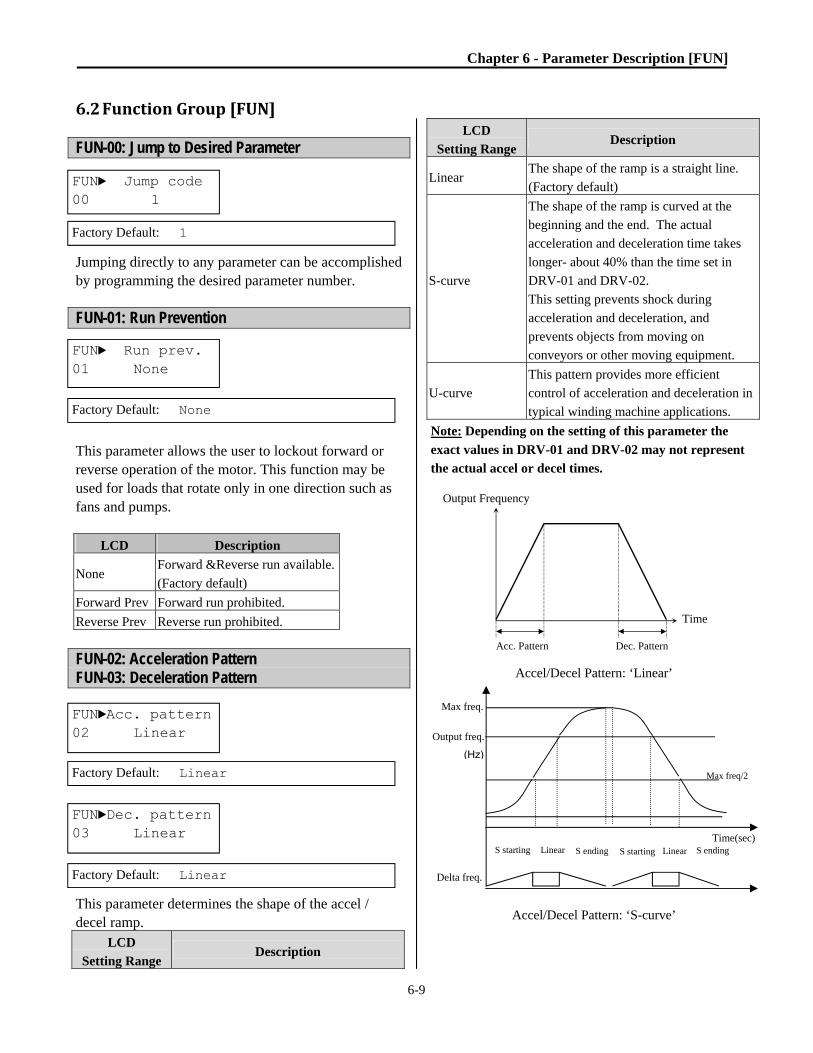
Chapter 6 - Parameter Description [FUN]
6-9
6.2 FunctionGroup[FUN] FUN-00: Jump to Desired Parameter Jumping directly to any parameter can be accomplished by programming the desired parameter number. FUN-01: Run Prevention This parameter allows the user to lockout forward or reverse operation of the motor. This function may be used for loads that rotate only in one direction such as fans and pumps.
LCD Description
None Forward &Reverse run available.
(Factory default)
Forward Prev Forward run prohibited.
Reverse Prev Reverse run prohibited.
FUN-02: Acceleration Pattern FUN-03: Deceleration Pattern This parameter determines the shape of the accel / decel ramp.
LCD
Setting Range Description
LCD
Setting Range Description
Linear The shape of the ramp is a straight line.
(Factory default)
S-curve
The shape of the ramp is curved at the
beginning and the end. The actual
acceleration and deceleration time takes
longer- about 40% than the time set in
DRV-01 and DRV-02.
This setting prevents shock during
acceleration and deceleration, and
prevents objects from moving on
conveyors or other moving equipment.
U-curve
This pattern provides more efficient
control of acceleration and deceleration in
typical winding machine applications.
Note: Depending on the setting of this parameter the
exact values in DRV-01 and DRV-02 may not represent
the actual accel or decel times.
Accel/Decel Pattern: ‘Linear’
Accel/Decel Pattern: ‘S-curve’
FUN► Jump code 00 1
Factory Default: 1
FUN► Run prev. 01 None
Factory Default: None
FUN►Acc. pattern 02 Linear
Factory Default: Linear
FUN►Dec. pattern 03 Linear
Factory Default: Linear
Output Frequency
Time
Acc. Pattern Dec. Pattern
Output freq.
Max freq.
(Hz)
S starting Time(sec)
Max freq/2
S ending S ending S starting Linear Linear
Delta freq.

Chapter 6 - Parameter Description [FUN]
6-10
Accel/Decel Pattern: ‘U-curve’ FUN-04: Start Curve for S-Curve Accel/Decel Pattern FUN-05: End Curve for S-Curve Accel/Decel Pattern These parameters change the curvature of the acceleration and deceleration ramps. They also affect the actual acceleration and deceleration times by the following formulas: Actual accel time = Preset accel time+ Preset accel time *Starting curve ratio/2 + Preset accel time * Ending curve ratio /2 Actual decel time = Preset decel time + Preset decel time * Starting Curve ratio/2 + Preset decel time * Ending curve ratio/2
FUN-10~12: Pre-heat This function allows the drive to apply low levels of DC current to the motor to prevent moisture from entering and condensation from occurring inside the motor when stopped. When active, the display shows DCB in the status field. The Pre-heat function is activated when FUN-10 [Pre-heat] is set to “Yes” and one of the multi-function input terminals (I/O-20~27) is set to the “Pre-heat” function. The Preheat function is only active when the drive is stopped and the defined terminal is activated.
FUN►Pre-HeatMode10 No
Factory Default: No
Output Frequency
Time
Acc. Pattern Dec. Pattern
FUN► Start Curve 04 50%
Factory Default: 50 %
FUN► End Curve 05 50%
Factory Default: 50%
Pre-heat DC
current [FUN-11]
10 sec
RUN
Pre-Heat
On% [FUN-12]
60 Hz
0 Hz
Mx
Terminal
DC Brake
terminal

Chapter 6 - Parameter Description [FUN]
6-11
FUN-11 [Pre-heat value] is set in percent of motor rated current. Adjustment range is 1% to 50%. FUN-12 [Pre-heat duty] sets the duty cycle for a 10 second interval. At 100% setting, DC current is continuously supplied to the motor. Adjustment range is 1% to 100%. Note: Because the drive is operating, many parameters cannot be changed when the pre-heat function is active. Remove the reference command at the terminal to turn off the pre-heat function before attempting to adjust parameters.
FUN-20: Start Mode This parameter sets the starting method of the drive.
FUN-21: Starting DC Magnetizing Time FUN-22: Starting DC Magnetizing Value When FUN-20 is set to DC-start, the drive will output the amount of dc current set in FUN-22 for the amount of time set in FUN-21. The purpose of these parameters is to stop a freewheeling motor before starting. The drive will start accelerating after the amount of time in FUN-21. FUN-22 [Starting DC Magnetizing Value] is the amount of DC Current applied to the motor and is set as percent of DRV-05 [Motor Rated Current]. Note: Do not set FUN-22 [Starting DC Magnetizing Value] higher than Inverter Rated Current. Otherwise, Motor Overheating or an Overload Trip may occur.
Note: DC-start is disabled when FUN-21 or 22 is set to “0”.
Note: DC-start is deactivated in Sensorless mode.
CAUTION If the pre-heat current or duty cycle is set too high motor overheating may result. Reduce FUN-11 [Pre-heat value] or FUN-12 [Pre-heat duty] if the inverter or motor becomes overheated.
FUN-20
Setting Range Function description
Accel
Acceleration to start
(Factory default)
Dc-start
Drive starts acceleration after
magnetizing DC current (see FUN-21
and FUN-22)
Flying-start
Drive matches the speed and starts
into a rotating motor. See AFN-22.
Time
Output Frequency
FX-CM ON
Time
Time
Run Command
FUN-22
FUN-22
TT1: FUN-21 [Starting DC Magnetizing Time] D1: FUN-22 [Starting DC Magnetizing
Output Current
TimD1
Output Voltage
FUN► DcSt value 22 50 %
Factory Default: 50 %
FUN► DcSt time 21 0.0 sec
Factory Default: 0.0 sec
FUN► Start Mode 20 Accel
Factory Default: Accel
FUN►PreHeatLevel 11 30%
Factory Default: 30%
Factory Default: 100%
FUN►PreHeatPerc 12 100%

Chapter 6 - Parameter Description [FUN]
6-12
FUN-23: Stop Mode This parameter sets the stopping method of the drive. LCD
Setting Range Description
Decel The drive stops using the
deceleration pattern.
Dc-brake
The drive stops with DC injection
braking. The drive will output a DC
voltage when the frequency goes
below the DC injection braking
frequency during deceleration.
Free-run
(Coast to stop)
The drive stops outputting voltage immediately when the stop signal is commanded.
Flux brake
Faster stopping times are available
by converting some of the
regenerating energy into heat at the
motor during deceleration. Flux
Brake will stop the motor as fast as
possible without tripping the drive.
☞ Caution: When DC braking or Flux braking is
used, discretion must be used as excessive motor heating may result if the load inertia is large, if the braking is done frequently, if the brake current is set too high, or if the brake time is set too long.
Stop Mode: Decel
Stop Mode: Free-run
FUN► Stop mode 23 Decel
Factory Default: Decel
Output Frequency
Time
FX-CM ON
Output Voltage
Time
Time
Stop Command
Output Frequency
Time
FX-CM ON
Output Voltage
Time
Time
Stop Command

Chapter 6 - Parameter Description [FUN]
6-13
FUN-24: DC Injection Braking Delay Time FUN-25: DC Injection Braking Frequency FUN-26: DC Injection Braking Time FUN-27: DC Injection Braking Value
DC Injection Braking Operation DC injection braking may be used to stop the motor more quickly than stopping by deceleration. This function is activated by selecting DC-brake in FUN-23.
The drive will decelerate to the frequency set in FUN-25. Upon reaching that frequency, the drive will wait the amount of time set in FUN-24. After waiting the amount of time in FUN-24, the drive will output the amount of voltage in FUN-27 for the amount of time in FUN-26. FUN-24 [DC Injection Braking Delay Time] is the amount of time the drive waits before outputting voltage after the drive has gone below the frequency in FUN-25. FUN-25 [DC Injection Braking Frequency] is the frequency at which the drive will start to output DC voltage during deceleration. FUN-26 [DC Injection Braking Time] is the time that the DC current is applied to the motor. FUN-27 [DC Injection Braking Value] is the DC current applied to the motor and is based on DRV-05, Rated Current of Motor. Caution: Do not set the value of FUN-27 too high as it may cause the motor to overheat or the drive to overload trip. Note: Do not set FUN-25 [DC Braking Frequency] too high. Otherwise excessive drive tripping may occur. FUN-28: Safety Stop
This function allows the drive to stop by decelerating the load upon loss of line power or a brownout condition. It can be very important to control the decelerating motor when power is lost depending on the application (for example to prevent check valve slamming in a pump system). The drive will use the regenerative energy from the motor and load to keep itself powered as it decelerates the motor under full
FUN► DcBr freq 25 5.00 Hz
Factory Default: 5.00 Hz
FUN► DcBr time 26 1.0 sec
Factory Default: 1.0 sec
FUN►DCBr dly tim 24 0.10 sec
Factory Default: 0.10 sec
FUN► DcBr value 27 50 %
Factory Default: 50 %
FUN► Safety Stop 28 No
Factory Default: No
Output Frequency
Time
FX-CM ON
Output Voltage
Time
Time
Stop Command
[DCBrFreq]
[DCBr Value]
t1 t2
t1: FUN-24 t2: FUN-26

Chapter 6 - Parameter Description [FUN]
6-14
control to a safe stop. See parameters AFN-46 (Load Inertia), AFN-52 (Decel Rate) and AFN-53 (Decel Percentage) to fine tune the operation of this function.
Note: This function can only be applied to applications that have a high enough inertia to provide enough stored energy to complete the deceleration profile. Deceleration time will depend on available load inertia. If line power returns and the drive has a valid run command the drive will accelerate the load back to its appropriate speed. There is a delay of 2 – 3 seconds after line power has returned before the drive will respond. If a Stop command is made, the drive will coast to a stop. FUN-29: Line Frequency This parameter sets the value of the incoming line frequency.
☞ Caution: This parameters will affect the settings
of other parameters such as Max frequency, Base frequency, and Upper limit. To set these related frequencies differently than the line frequency, the user should set these parameters manually AFTER setting FUN-29. FUN-30: Maximum Frequency FUN-31: Base Frequency FUN-32: Starting Frequency FUN-30 [Maximum Frequency] is the highest frequency the drive will output.
CAUTION Consult with the motor manufacturer before exceeding the base speed of the motor. Verify that the driven equipment can operate at the maximum speed set. FUN-31 [Base Frequency] is the frequency where the drive outputs full motor rated voltage. This parameter is normally set to 50Hz or 60Hz. When using a 60Hz motor, set this parameter to 60Hz. FUN-32 [Starting Frequency] is the frequency where the drive starts to output voltage. For example, if FUN-32 it is set to 5Hz, the drive starts running when the reference frequency is 5 Hz. Caution: Note that these functions are reset when FUN-29 [Line Frequency] is set. Caution: Note that improper setting of FUN 31 [Base Frequency] can cause overload trips and lack of motor torque.
FUN► Max freq 30 60.00 Hz
Factory Default: 60.00 Hz
FUN► Base freq 31 60.00 Hz
Factory Default: 60.00 Hz
FUN► Start freq 32 0.50 Hz
Factory Default: 0.50 Hz
Output Voltage
Rated Voltage
Output Frequency
FUN-32. FUN-31.
FUN-30
FUN► Line Freq 29 60.00 Hz
Factory Default: 60.00 Hz

Chapter 6 - Parameter Description [FUN]
6-15
FUN-33: Frequency Limit Selection FUN-34: Low Limit Frequency FUN-35: High Limit Frequency When FUN-33 is set to Yes, it allows the user to set high and low limits for the drive. The drive will operate at the upper or the lower limit when the frequency reference is outside the frequency limit range. Freq. limit: Yes Note: If the frequency reference is below the frequency low limit, the drive will operate at the low limit.
FUN-40: Volts/Hz Pattern This is the pattern of voltage/frequency ratio. Select the proper V/F pattern according to the load. The motor torque is dependent on this V/F pattern. [Linear] pattern is used for constant torque loads. This pattern maintains a linear volts/frequency ratio from zero to base frequency. This pattern is appropriate for applications that require high starting torque. The performance will be improved with the help of AFN-67~69 [Torque boost]. [Square] pattern is used for variable torque loads such as fan and pumps. This pattern maintains a “squared” volts/hertz ratio and will increase energy savings in variable torque applications. [User V/F] pattern is used for special applications. Users can adjust the volts/frequency ratio according to their application. This is accomplished by setting the frequency and voltage at four points between starting frequency and base frequency. The four points of voltage and frequency are set in FUN-41 through FUN-48. V/F Pattern: Linear
V/F Pattern: Square
FUN► Freq limit 33 No
Factory Default: No
FUN► Lim Lo Freq 34 0.50 Hz
Factory Default: 0.50 Hz
FUN► Lim Hi Freq 35 60.00 Hz
Factory Default: 60.00 Hz
FUN► V/F pattern40 Linear
Factory Default: Linear
Output Voltage
Output Frequency
Freq.
100%
Output Voltage
Output FrequencyFreq.
100%
Output Frequency
Freq. Max
Freq setting
FUN-35
FUN-34
Reference Frequency
Output Frequency
10V, 20mA

Chapter 6 - Parameter Description [FUN]
6-16
FUN-41 ~ FUN-48: User V/F Frequency and Voltage
□
□
These functions are available only when ‘User V/F’ is selected in FUN-40 [V/F pattern]. Users can make a custom V/F pattern by setting four points between FUN-32 [Starting Frequency] and FUN-31 [Base Frequency].
User V/F
Note: When the ‘User V/F’ is selected, the torque boost of AFN-67 through AFN-69 is ignored.
FUN-49: AC Input Voltage Adjustment 230V models display VAC 230.0V (default) 460V models display VAC 460.0V (default) 600V models display VAC 575.0V (default) The actual input voltage should be measured and the percentage calculated based on the following: % = Measured Input / default x 100% Parameter Display Default Setting
FUN-49 AC Input
Volt 100 [%] 73 – 115 [%]
Note: It is very important to set this parameter correctly as this parameter affects the drive’s LV trip (low voltage trip) level and is also used by the Sensorless Vector control algorithm. FUN-50: Motor Rated Voltage This parameter sets the actual motor rated voltage. This information can be found on the motor nameplate. The drive will automatically adjust its output voltage to compensate for any input voltage fluctuations. If this parameter is set to 0V the drive will automatically detect the incoming voltage and use the incoming voltage level as the motor rated voltage. Use caution when setting this value to 0V (auto), as the drive may not always sense the proper input voltage, if the input voltage is too high. Note: When the actual input voltage is less than FUN-50 [Motor rated voltage] the maximum output voltage will be equal to the input voltage.
FUN► User freq 1 41 15.00 Hz
Factory Default: 15.00 Hz
FUN► User volt 1 42 25 %
Factory Default: 25 %
FUN► User volt 4 48 100 %
Factory Default: 100 %
FUN► User freq 4 47 60.00 Hz
Factory Default: 60.00 Hz
Output Voltage
Output Frequency
Freq. Base
100%
FUN-42
FUN-41
FUN-45
FUN-44FUN-46
FUN-48
FUN-47
FUN-43
FUN► VAC 460.0V 49 100.0 %
Factory Default: 100.0 %
FUN► Motor Volt50 460 V
Factory Default: 230V, 460V, 575V Model Dependant

Chapter 6 - Parameter Description [FUN]
6-17
FUN-51~52: Energy Save, Energy Save Level This function is used to reduce the output voltage in applications that do not require high torque and current when running at steady speed. The drive will reduce its output voltage after accelerating to the reference frequency (steady speed) if the energy save level is set at a non-zero value.
CAUTION This function may cause over-current trips to occur due to the lack of output torque when used on a fluctuating load. If the manual energy saver value is reduced too much, the applied motor voltage may be too low for correct motor operation and motor stalling and/or overheating may result. Note: When Energy Save is ON, it may take longer to decelerate to a stop.
FUN-51 Setting Range
Description
None Disabled (Factory setting)
Manual Energy save ON by decreasing the output with the value set in FUN-52.
Auto Energy save ON automatically. Param LCD Name Default Range
FUN-52 Manual Save %
Energy save %
0 [%] 0~30 [%]
FUN-54: Integrating Wattmeter This parameter displays both MWh and kWh. Ex) 1500kWh
Max Cumulative value is displayed in FUN-54 as shown below. Ex) 9,999,999.9 kWH (maximum reading)
Press [PROG] key for 5 sec to reset the value stored in FUN-54. Note: FUN-54 values may differ from the actual values slightly due to measurement tolerance issues. FUN-55: Inverter temperature The power section’s temperature (in Celsius) is displayed in FUN-55.
110 %
85 %
100 %
Output V
Inpu
t vol
tage
Motor rated V
[FUN-50]
100%
85%
110%
85%
FUN►Manual save% 52 0 %
Factory Default: 0 %
FUN► Energy save 51 None
Factory Default: 0
FUN► Inv. Temp 55 44
Factory Default: 44
FUN► Kilowatts 54 9999M999.9KWh
FUN► Kilowatts 54 1M 500.0KWh

Chapter 6 - Parameter Description [FUN]
6-18
FUN-56: Motor temperature The Motor temperature (in Celsius) detected by an externally connected thermal sensor is displayed in FUN-56. See I/O-98 for more description. FUN-57: No Motor Sel FUN-58: No Motor Level FUN-59: No Motor Time Low Output Current Level Detection With FUN-57 set to “Yes”, these parameters can be used to generate a trip when the output current is below a set level (FUN-58) for a period of time (FUN-59). The current level is based on the set Motor rated current, DRV-05. A “HW-Diag” fault will occur displaying the message “No Motor Trip”. No Motor Connection These parameters can be used to detect an open output contactor or disconnect switch between drive output and the motor.
FUN-64: Overload Warning Level FUN-65: Overload Warning Time One of the auxiliary relay outputs must be configured as “OL” (parameters I/O-76 through I/O-79) to activate OL Warning. The drive will then generate an alarm signal (contact closure) and the display will flash “OL Warning” when the output current has reached the FUN-64 [Overload Warning Level] for the FUN-65 [Overload Warning Time]. The alarm signal will continue for the FUN-65 time even if the current has fallen below the FUN-64 current level. Note: FUN-64 is set as the percentage of DRV-05 [Rated Motor Current].
Overload Warning
Description LCD Display Setting Range
No Motor Selection No Motor Sel No/Yes
Trip Current Level No Motor Level 5 – 100 [%]
Trip Time Setting No Motor Time 0.5 – 10.0 [sec]
FUN► OL level 64 110 %
Factory Default: 110 %
FUN► OL time 65 10.0 sec
Factory Default: 10.0 sec
FUN► Motor Temp 56 0
Factory Default: 0
FUN► No Motor Sel 57 No
Factory Default: No
FUN► NoMotorLevel 58 25 %
Factory Default: 5
FUN► NoMotorTime 59 3.0 sec
Factory Default: 3.0 sec
t1: FUN-65 [Overload Warning Time]
Output Current
Time
Time
FUN-64[OL Level]
FUN-64[OL Level]
AX-CX (OL) ON
t1 t1

Chapter 6 - Parameter Description [FUN]
6-19
FUN-66: Overload Trip Selection FUN-67: Overload Trip Level FUN-68: Overload Trip Delay Time When set to “yes”, the drive will trip and display a fault message when the output current persists over the FUN-67 [Overload Trip Level] for the time of FUN-68 [Overload Trip Time]. This function protects the drive and motor from abnormal load conditions. The drive cannot be reset immediately after an overload trip. A cool down period of approximately one minute is required prior to resetting the drive. Note: The set value is the percentage of DRV-05 [Rated Motor Current].
Overload Trip Operation
FUN-69: Input/Output Phase Loss Protection (Bit Set) This function will cause the drive to trip upon a phase loss or opening. Phase loss detection can be selected for the input as well as the output. FUN-69 [Phase Loss Protection Mode Selection]
Setting Range FUN-69 Description
Bit 2 Bit 1 Bit 0
0 0 1 001 Output phase loss
protection active
0 1 0 010 Input phase loss
protection active
1 0 0 100
Phase loss protection
during exchange
operation active
Bit 0: Output phase loss protection Enable/Disable 0: Disabled for Output phase loss protection. 1: Enabled for Output phase loss protection. The drive will fault upon loss of output phase. Bit 1: Input phase loss protection Enable/Disable 0: Input phase loss protection disabled. 1: Input phase loss protection enabled. The drive will shut down and stop upon loss of input phase. Bit 2: Protection Enable/Disable selection at Exchange function 0: Disabled at Exchange function (Inverter-Commercial line exchange). 1: Enabled at Exchange function.
FUN► OLT select 66 --- No ---
Factory Default: No
FUN► OLT level 67 120 %
Factory Default: 120 %
FUN► OLT time 68 60.0 sec
Factory Default: 60.0 sec
FUN► Trip select69 001
Factory Default: 001
Output Current
Time
FUN-67[OLT Level]
FUN-67[OLT Level]
Output Frequency
FUN- 68 [OLT Time]
Overload

Chapter 6 - Parameter Description [FUN]
6-20
FUN-70: Stall Prevention Mode FUN-71: Stall Prevention Level This function is used to prevent the motor from stalling by reducing the drive output frequency until the motor current decreases below the stall prevention level. When enabled (FUN-70 set to “yes”), this function is active for all modes of operation: acceleration, steady speed, and deceleration. Note: FUN-71 is set as the percentage of DRV-05 [Rated Motor Current]. Note: When enabled, the maximum level will be limited to 120% of Inverter rated Current. Note: The stall level will be automatically reduced if the drive is operated at the frequency higher than base frequency.
Stall Prevention during Acceleration
Note: The actual Acceleration time may extend due to stall prevention during Acceleration. Note: The drive starts deceleration when a Stop command is applied even while a motor stall state is present. Note: The output frequency and hence the motor speed may oscillate due to stall prevention action during constant run mode. Note: The actual deceleration time (i.e. the time for the motor to slow down or stop) may lengthen due to stall prevention.
Stall Prevention during Constant Run
Stall Prevention during Deceleration
FUN► Stall prev. 70 No
Factory Default: No
FUN► Stall level 71 100 %
Factory Default: 100 %
Time
DC Link Voltage
Time
Output Frequency
390VDC or780VDC
Output Current
Time
Output Frequency
Time
FUN-71[Stall level]
FUN-71[Stall Level]
Output Current
Time
Output Frequency
Time
FUN-71[Stall Level]
FUN-71[Stall Level]
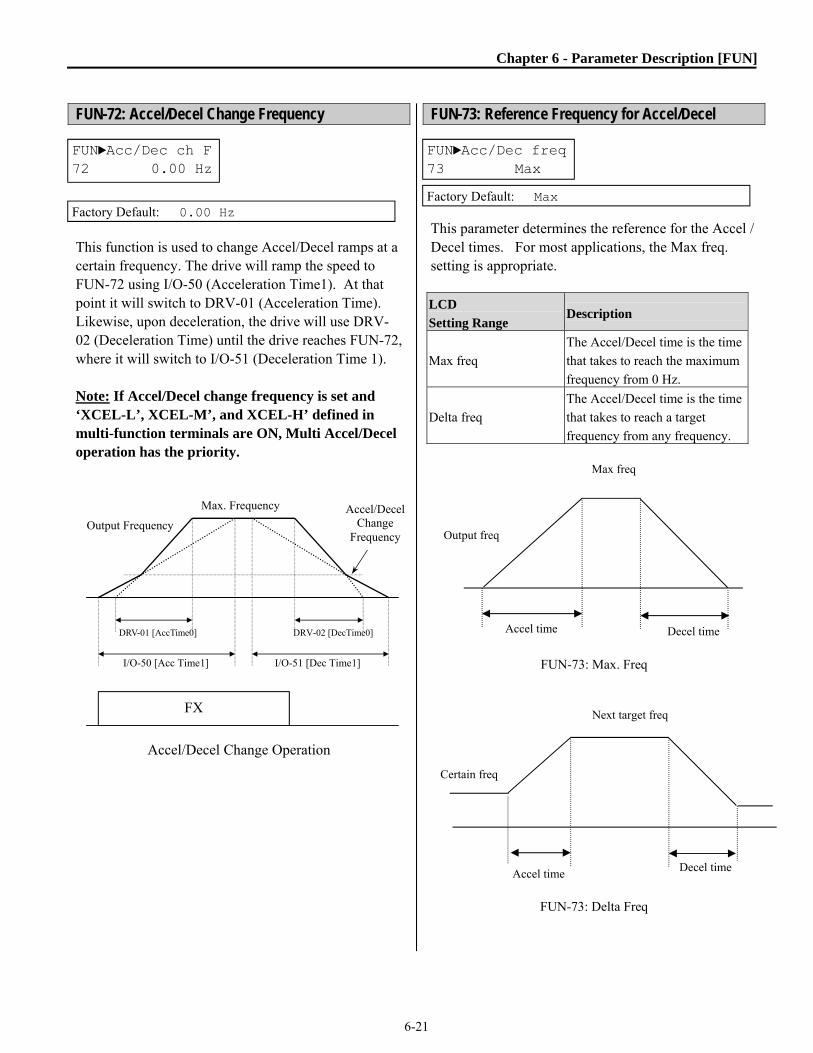
Chapter 6 - Parameter Description [FUN]
6-21
FUN-72: Accel/Decel Change Frequency This function is used to change Accel/Decel ramps at a certain frequency. The drive will ramp the speed to FUN-72 using I/O-50 (Acceleration Time1). At that point it will switch to DRV-01 (Acceleration Time). Likewise, upon deceleration, the drive will use DRV-02 (Deceleration Time) until the drive reaches FUN-72, where it will switch to I/O-51 (Deceleration Time 1). Note: If Accel/Decel change frequency is set and ‘XCEL-L’, XCEL-M’, and XCEL-H’ defined in multi-function terminals are ON, Multi Accel/Decel operation has the priority.
Accel/Decel Change Operation
FUN-73: Reference Frequency for Accel/Decel This parameter determines the reference for the Accel / Decel times. For most applications, the Max freq. setting is appropriate. LCD
Setting Range Description
Max freq
The Accel/Decel time is the time
that takes to reach the maximum
frequency from 0 Hz.
Delta freq
The Accel/Decel time is the time
that takes to reach a target
frequency from any frequency.
FUN-73: Max. Freq
FUN-73: Delta Freq
FUN►Acc/Dec ch F 72 0.00 Hz
Factory Default: 0.00 Hz
Output Frequency
FX
Max. Frequency Accel/Decel Change
Frequency
DRV-01 [AccTime0] DRV-02 [DecTime0]
I/O-50 [Acc Time1] I/O-51 [Dec Time1]
FUN►Acc/Dec freq73 Max
Factory Default: Max
Certain freq
Accel time Decel time
Next target freq
Output freq
Accel time Decel time
Max freq

Chapter 6 - Parameter Description [FUN]
6-22
FUN-74: Accel/Decel Time Scale This parameter is used to change the number of significant digits displayed for the Accel and Decel parameters. It also affects the time scale (maximum range) of the acceleration and deceleration times.
LCD
Setting Range Description
0.01 sec
The Accel/Decel time is changed by
10 msec. The maximum setting range
is 60 seconds.
0.1 sec
The Accel/Decel time is changed by
100 msec. The maximum setting
range is 600 seconds.
1 sec
The Accel/Decel time is changed by 1
sec. The maximum setting range is
6000 seconds.
FUN-75: Up/Down Save Mode FUN-76: Up/Down Save Frequency These parameters are used in conjunction with the digital input terminals (I/O-20 ~ I/O-27) when set to Up and Down (EMOP) control. The saved frequency (FUN-76, view only) is the frequency at the time the input terminal (Up/Down) is released (deactivated). Enable the Up/Down Save mode with FUN-75 set to “yes”. The saved frequency can be cleared with a digital input set to “Up/Dn Clr”.
Up Down Save
FUN-80: Over Heat Warning Level This parameter is used to activate an auxiliary relay when set to “OH Warn” with parameters I/O-76~I/O-79. The percentage is based on an Over Heat Fault occurring at 100%. The actual trip temperature is based on the drives internal thermistor(s) and varies depending on horse power rating of drive.
FUN► Time scale 74 0.1 sec
Factory Default: 0.1 sec
FUN►UpDnSaveMode75 No
FUN►UpDnSaveFreq 76 0.00 Hz
FUN►OH Warn Levl 80 90%

Chapter 6 - Parameter Description [FUN]
6-23
FUN-81: Analog Stall Source FUN-82: Current Limit Level When FUN-70 (Stall Mode) is set to “yes” user can select a remote variable source (I, V1, Pulse) to limit current instead of a fixed level (FUN-71). The FUN-82 percentage is at the maximum of the analog signal (FUN-81). FUN-81 Setting Range
Description
None Uses FUN-71 level.
I 0(4)-20 mA signal used for current limit.
V1 0-10V signal used for current limit.
Pulse 0-100kHz signal used for current limit.
Ex) FUN-81 set to “V1”, 0 - 10V scale FUN-82 set to 150% (10V = 150%) With 5V input at V1: Stall level = 150% x 5V/10V = 75% Current is limited to 75% of DRV-05, motor amps. The calculated stall level is displayed in FUN-71.
FUN► AnaStall Src 81 None
FUN►Max Ana Perc 82 100%

6-24
NOTES:

Chapter 6 - Parameter Description [AFN]
6-25
6.3 AdvancedFunctionGroup[AFN] AFN-00: Jump to Desired Parameter Jumping directly to any parameter can be accomplished by programming the desired parameter number. AFN-01: Last trip 1 AFN-02: Last trip 2 AFN-03: Last trip 3 AFN-04: Last trip 4 AFN-05: Last trip 5 AFN-06: Erase Trips
□
□
□
These parameters display the past five faults of the drive. AFN-01 is the most recent fault. Use the PROG, ▲ and ▼ keys to check the fault log content. Output frequency, output current, drive temperature, DC Link Voltage and the mode of operation when the fault occurred, are displayed. Press the ENTER key to exit. AFN-83 [Last Trip Time] is the elapsed time after the last trip. Note: Faults such as WDOG error, EEP error, and ADC Offset, HW-Diag are not resettable. Repair the fault before turning on the power.
This function erases all fault histories of AFN-01 to AFN-05 from memory. However, AFN-83 [Last Trip Time] cannot be reset. AFN-07: Dwell Time AFN-08: Dwell Frequency When a run command is initiated, the drive will ramp to the dwell frequency and remain there for the dwell time. Note: If the dwell time is set at ‘0’, this function is not available. Note: Do not set the Dwell frequency above the frequency command. Otherwise, it may lead to incorrect operation. Note: This function is disabled when operating in Sensorless control mode.
Dwell Function
AFN► Jump code 00 1
Factory Default: 1
AFN► Last trip-1 01 None
Factory Default: None
AFN► Last trip-5 05 None
Factory Default: None
AFN► Erase trips 06 --- No ---
Factory Default: No
AFN► Dwell freq 08 5.00 Hz
Factory Default: 5.00 Hz
AFN► Dwell time 07 0.0 sec
Factory Default: 0.0 sec
AFN-07
AFN-08
Time
RUN
Output freq.

Chapter 6 - Parameter Description [AFN]
6-26
AFN-10 ~ AFN-16: Frequency Jump
□
□
□
These parameters allow the user the ability to lock out certain frequencies that can cause resonance in the driven equipment. Three different jump frequency ranges may be set. The drive will accelerate and decelerate through the jump frequencies, but will not be allowed to sit at the locked out frequencies.
Frequency Jump Note: When the reference frequency is set between the jump frequency low/high limit, it follows the low limit frequency, marked by “”. Note: If jump range 1 and range 2 are overlapped, the lower freq. will become a low limit.
AFN► Jump freq 10 --- No ---
Factory Default: No
Output Frequency
Freq. Max
ReferenceFrequency10H 20H 30H
AFN-16AFN-15
AFN-14AFN-13
AFN-12AFN-11AFN► jump Lo 1
11 10.00 Hz
Factory Default: 10.00 Hz
AFN► jump Hi 1 12 15.00 Hz
Factory Default: 15.00 Hz
AFN► jump Lo 3 15 30.00 Hz
Factory Default: 30.00 Hz
AFN► jump Hi 3 16 35.00 Hz
Factory Default: 35.00 Hz

Chapter 6 - Parameter Description [AFN]
6-27
AFN-20: Power ON Start Selection If AFN-20 is set to ‘No’, upon loss of power, the user will be required to open the run command and then close the run command to restart the drive. If AFN-20 is set to ‘Yes’, and the run command remains closed, the drive will restart after power is restored. The drive will start at its normal starting frequency and accelerate normally based on its settings. If the motor is still rotating when power is restored, the drive may trip. To avoid this trip, use ‘Speed Search’ function (AFN-22).
CAUTION Careful attention must be directed to this function as the motor will start to run immediately upon applying AC input power.
Power ON Start: No
Power ON Start: Yes
Note: When setting ‘Power ON Start’ to ‘Yes’, make sure to use appropriate warning notices and safety interlocks to minimize the potential for injury or equipment damage. AFN-21: Restart After a Fault Reset If AFN-21 is set to ‘No’, upon resetting a fault, the user will be required to open the run command and then close the run command to restart the drive. If AFN-21 is set to ‘Yes’, and the run command remains closed, the drive will restart after the fault is reset. The drive will start at its normal starting frequency and accelerate normally based on its settings. If the motor is still rotating when power is restored, the drive may trip. To avoid this situation, use ‘Speed Search’ function (AFN-22).
Reset restart: No
Reset Restart: Yes
AFN►Power-on run 20 No
Factory Default: No
Input Power
Time
FX-CM ON Time
Start
Power On
Output Frequency
Time
AFN► RST restart21 No
Factory Default: No
Output Frequency
Time
FX-CM ON Time
RST-CM ON Time
ON
No Effect Start
Tripped
Output Frequency
Time
FX-CM ON Time
RST- ON Time
Start
Tripped
Input Power
Time
FX-CM ON TimeON
No Start
Power On
Output Frequency
Time

Chapter 6 - Parameter Description [AFN]
6-28
AFN-22: Restart after Instantaneous Power Failure AFN-23: Speed Search This function is used to permit automatic restarting into a spinning motor after an Instantaneous Power Failure. When AFN-22 is set to “yes”, the Speed Search function is activated regardless of FUN-20 (Start Mode) setting. AFN-20 (Power On Run) must also be set to “yes” and the run command active (Fx closed) to perform the Speed Search Flying Start. See also AFN-27, Flying Percentage and AFN-46, Inertia Rate. Speed Search synchronizes the drive output (Voltage, Frequency, and Direction) to that of the spinning motor. This is accomplished by sweeping the output frequency from the reference frequency down while increasing the output voltage from zero up. Note: Speed search during Acceleration can also be independently activated by setting FUN-20 [Start Mode] to “Flying Start”.
Speed Search Operation
AFN-24: Auto Fault Reset AFN-25: Number of Auto Retry AFN-26: Delay Time Before Auto Retry When AFN-24 is set to “yes” the drive has the ability to automatically reset itself after a fault occurs. The drive will reset itself up to the number of times set in AFN-25. The drive will wait the amount of time set in AFN-26 after a fault before attempting a restart. The motor may be coasting when the restart occurs. To catch the spinning load, use the speed search function, AFN-22. Some faults cannot be automatically reset. These include Low Voltage (LV) trip, Inverter Disable (BX) and OC-2 Output Short circuit.
Input Power
Time
Motor Speed
Time
Output Frequency
Output Voltage
Time
Time
Input Power loss
AFN► IPF Mode 22 No
Factory Default: No
AFN► estimated SS 23
Factory Default: estimated SS
AFN►Retry Mode 24 No
AFN►Retry number25 0
AFN►Retry delay 26 1.0 sec

Chapter 6 - Parameter Description [AFN]
6-29
Note: The drive decreases the retry number by one as each fault occurs. If a trip does not occur after the drive is running for 30 seconds, the drive increases the retry number by one until it reaches the amount in AFN-25.
AFN-27: Flying Percentage
This parameter limits the output current during Speed Search/Flying Start. Percentage is based on DRV-05, Motor Amps.
AFN-40: Motor Capacity Selection AFN-41: Number of Motor Poles AFN-42: Rated Motor Slip AFN-44: No Load Motor Current AFN-45: Motor Efficiency AFN-46: Load Inertia If the user does not set these values, the drive will use factory default values. This parameter sets the motor capacity. The following parameters are automatically set according to motor capacity. AFN-42 Rated Motor Slip DRV-05 Rated Motor Current (Recheck DRV-05 after changing HP setting). AFN-44 No Load Motor Current AFN-62 Stator Resistance AFN-63 Rotor Resistance AFN-64 Leakage Inductance If AFN-44 [Motor No-load Current] is not correct, run the drive without the load in V/F mode and check the current at the constant run state and enter this value to AFN-44 [No load current]. This is used to display the motor speed. If you set this value to 2, the drive will display 3600 rpm instead of 1800 rpm at 60Hz output frequency. (See motor nameplate)
CAUTION Careful attention must be directed to this function as the motor restarts automatically after a fault is reset.
AFN►Motor select40 7.5HP
Factory Default: 7.5 HP Model Dependant
AFN► Pole number41 4
Factory Default: 4
Output Frequency
Time
1st Fault 2nd Fault
Restart with Speed Search
Restart with Speed Search
t t
t: AFN-26
AFN► Flying Perc 27 70%

Chapter 6 - Parameter Description [AFN]
6-30
This is used in ‘Slip Compensation’ control, AFN-60. If you set this value incorrectly, the motor may stall during slip compensation control (See motor nameplate). Motor rated slip freq [Hz] = (Rated input freq. [Hz] – (Motor rpm * P/120) P: Number of motor poles (Ex) In the case of 60Hz, 4 pole, 1760 rpm motor Motor rated slip freq [Hz] = (60[Hz]-(1760[rpm] * 4/120))
= 60[Hz]-58.67[Hz] =1.33[Hz] If this value is not right, check the current after operating in V/F mode without a load connected and enter that current value. Note: Verify the correct value for AFN-44 [Motor No-load Current]. Otherwise, the Sensorless vector control may not operate properly. Note: The default motor parameters may differ with the actual motors used. In this case, enter the nameplate value of your motor to the corresponding parameters. If the motor rating exceeds the drive capacity, poor performance may result. The value of this parameter is used for calculating the output wattage when AFN-81 is set to ‘Watt’.
This parameter is used by many drive functions such as Sensorless Vector control [AFN-60], Speed Search [AFN-22], and Safety Stop [FUN-28]. When using these functions, the inertia value can be fine tuned to provide better performance. The available range is 1to 40. Set to low numbers for loads that have low load inertias for a quicker search time. Set to higher numbers for loads that have high load inertias for a slower search time. During Speed Search operation, if overvoltage trips occur increase the value of this parameter and retest. During Safety Stop operation, if undervoltage trips occur then decrease the value of this parameter. If overvoltage trips occur increase the value of this parameter and retest. The higher the inertia setting the slower the deceleration rate is during Safety Stop operation. AFN-47: Gain for Motor Speed Display This parameter is used to change the motor speed display to rotating speed (r/min) or the load’s mechanical speed (m/min). The display is calculated by following equation: Rotating speed (r/min) = 120 * F / P * Motor RPM Display Gain [AFN-47] Where, F=Output frequency, P= motor pole number
AFN► Rated-Slip 42 2.34 Hz
Factory Default: 2.34 Hz Automatically set according to the motor capacity (AFN-40)
AFN► Noload-Curr 44 6.6 A
Factory Default: 6.6 A Automatically set according to the motor capacity (AFN-40)
Factory Default: 86 % Automatically set according to the motor capacity (AFN-40)
Factory Default: 10
AFN► RPM factor 47 100 %
Factory Default: 100 %
AFN► Efficiency 45 86 %
AFN►Inertia rate46 10
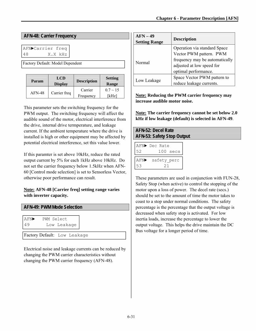
Chapter 6 - Parameter Description [AFN]
6-31
AFN-48: Carrier Frequency
Param LCD
Display Description
Setting
Range
AFN-48 Carrier freq Carrier
Frequency
0.7 ~ 15
[kHz]
This parameter sets the switching frequency for the PWM output. The switching frequency will affect the audible sound of the motor, electrical interference from the drive, internal drive termperature, and leakage current. If the ambient temperature where the drive is installed is high or other equipment may be affected by potential electrical interference, set this value lower. If this paramter is set above 10kHz, reduce the rated output current by 5% for each 1kHz above 10kHz. Do not set the carrier frequency below 1.5kHz when AFN-60 [Control mode selection] is set to Sensorless Vector, otherwise poor performance can result. Note: AFN-48 [Carrier freq] setting range varies with inverter capacity. AFN-49: PWM Mode Selection Electrical noise and leakage currents can be reduced by changing the PWM carrier characteristics without changing the PWM carrier frequency (AFN-48).
AFN – 49 Setting Range
Description
Normal
Operation via standard Space Vector PWM pattern. PWM frequency may be automatically adjusted at low speed for optimal performance.
Low Leakage Space Vector PWM pattern to reduce leakage currents.
Note: Reducing the PWM carrier frequency may increase audible motor noise. Note: The carrier frequency cannot be set below 2.0 kHz if low leakage (default) is selected in AFN-49. AFN-52: Decel Rate AFN-53: Safety Stop Output These parameters are used in conjunction with FUN-28, Safety Stop (when active) to control the stopping of the motor upon a loss of power. The decel rate (secs.) should be set to the amount of time the motor takes to coast to a stop under normal conditions. The safety percentage is the percentage that the output voltage is decreased when safety stop is activated. For low inertia loads, increase the percentage to lower the output voltage. This helps the drive maintain the DC Bus voltage for a longer period of time.
AFN►Carrier freq 48 X.X kHz
Factory Default: Model Dependent
AFN► PWM Select 49 Low Leakage
Factory Default: Low Leakage
AFN► Dec Rate 52 100 secs
AFN► safety_perc 53 21

Chapter 6 - Parameter Description [AFN]
6-32
AFN-60: Control Mode Selection Selects the control mode of the drive.
AFN-60 Setting Description V/F V/F Control Slip compensation Slip compensation
Sensorless Sensorless vector control speed operation
◈ V/F control: This parameter provides a constant voltage/frequency ratio. It is recommended for most general-purpose applications. To increase the starting torque with this method, increase the torque boost function. Related function: AFN-67~69 [Torque boost] ◈ Slip compensation: This function is used to maintain a constant motor speed, even with varying loads. To keep the motor speed constant, the actual output frequency will change in response to varying loads. The amount of frequency that the load varies is limited by the Rated Slip, (AFN-42). For example, when the motor speed decreases below the reference speed (frequency) due to a heavy load, the drive increases the output frequency higher than the reference frequency to increase the motor speed. The drive increases or decreases the output by the delta frequency shown below. Motor parameters AFN-41~46 and DRV-05 are automatically determined by AFN-40 [Motor selection]. The default settings are typically acceptable; however the parameters may be fine-tuned if necessary. AFN-40~46, DRV-05 [Motor related parameters for Slip Compensation]
Param LCD
Display Description
AFN-40 Motor select Select motor capacity AFN-42 Rated-Slip Motor rated slip (Hz)
DRV-05 Rated-Curr Motor rated current (rms)
AFN-44 Noload-Curr Motor no load current (rms)
AFN-45 Efficiency Motor efficiency (%) AFN-46 Inertia rate Motor inertia rate
Note: Incorrectly setting AFN-44 [Motor No-load Current] may degrade the Sensorless Vector control performance. ◈ Sensorless Vector speed control operation: Use sensorless vector control when 1) high starting torque is required at low speeds 2) the load fluctuates 3) fast torque response times are needed. For proper operation set AFN-40~46, DRV-05 [Motor parameters] and AFN-60 [Control mode select] properly. Set “Yes” in AFN-61 [Auto tuning] first before using this control. Related parameters: AFN-40~46, DRV-05, AFN-60, AFN-62~66 Parameter LCD display Parameter AFN-62 RS Stator resistance AFN-63 Lsigma Leakage inductance AFN-65 SL P-gain Sensorless P gain AFN-66 SL I-gain Sensorless I gain Guide for Optimal Use of Sensorless Vector Control For optimum use of sensorless vector control, the following conditions should be met. If one of the following conditions is not satisfied, the drive and motor may not work properly due to insufficient torque, cogging, or excessive motor noise. In any of the following situations are not satisfied, it is recommended to use V/F Control or Slip Compensation control instead of sensorless vector control. ▣ The motor capacity should be equal to or one horsepower level lower than the drive capacity.
AFN►Control mode 60 V/F
Factory Default: V/F
Delta freq (Slip Comp. Freq.) = Motor Rated slip *
(Output current - Motor No load current) / (Motor rated
current - Motor No load current)
Output freq = Reference freq + Delta freq

Chapter 6 - Parameter Description [AFN]
6-33
▣ The drive should only use one set of motor parameters. The drive should not be set to use the second set of motor parameters. ▣ For best performance, the auto tuning feature in AFN-61 should be used. ▣ Set the appropriate values for the overload limit function and the stall prevention. The values set should exceed 100% of the rated motor current. ▣ When using analog signals to control the speed of the drive, the wires should be shielded and installed to reduce electrical interference. ▣ The number of motor poles should be 2, 4 or 6. ▣ The distance between the drive and the motor should not exceed 100m (328 ft). CAUTIONS WHEN USING SENSORLESS VECTOR CONTROL ▣ Forced-cooling should be used for the motor when the average operating speed is under 20Hz and more than 100% load is applied. ▣ The motor may rotate 0.5% faster than the maximum speed under light loads or if the motor temperature does not reach normal operating temperature. ▣ Use the auto-tuning feature when the motor is at normal temperature (average temperature where the motor normally operates). ▣ The output torque may be reduced when an output filter option is used between the drive and the motor. ▣ Overcurrent trips may occur if AFN-62 [Stator resistance] is set to more than double the auto-tuned value.
Additional Tuning for Sensorless Vector Control ▣ Adjust the AFN–44 [No Load Motor Current (RMS)] value larger or smaller by 5% if the measured current is higher or lower than that of V/F control when under a light load. ▣ Adjust the AFN–42 [Rated Motor Slip] value larger or smaller by 5% if the actual speed is faster or slower than that of V/F control with rated load.
AFN-61~63: Auto tuning
All of the motor parameters can be tuned by setting AFN-61 to “YES”. Auto tuning is deactivated when “No” is selected. The auto tuning function automatically measures the motor parameters needed for Sensorless Vector control and Auto Torque Boost such as stator resistance, rotor resistance, leakage inductance and no-load current. Note: The rated current, voltage, efficiency and slip described in the motor nameplate should be entered before performing auto tuning. If efficiency is not indicated on the nameplate, use the default value.
These parameters display default settings based on motor horse power, set with parameter AFN-40. When Sensorless Vector control is selected in AFN-60, and Auto tuning is performed with AFN-61, the values detected during auto tuning are displayed.
AFN► Auto tuning 61 NO
Factory Default: NO
AFN► Stator Resistance 62 Rs
AFN► Leakage Inductance 63 Ls

Chapter 6 - Parameter Description [AFN]
6-34
AFN-64: Pre-excitation Time When the start command (FWD or REV) is issued, the drive will pre-excite the motor automatically for the time specified by this parameter. This function is used in order to fully magnetize the motor so that full torque can be produced immediately upon starting the motor. After AFN-64 [Pre-excitation Time] elapses the drive will start normal operation as shown in the following graph.
Param LCD
display
Factory
setting
Setting
range
AFN-64 PreExTime 1 [sec] 0 ~ 60 [sec]
Pre-exite time
AFN-65: P Gain for Sensorless Control AFN-66: I Gain for Sensorless Control SL P-gain is the proportional gain of the speed loop controller during Sensorless Vector control. If this value is set high, you can get fast speed response characteristics. However, if this value is set too high, the steady state characteristics may become unstable. The default settings are typically acceptable, and this parameter should only be changed to increase the performance of the system. SL I-gain is the integral gain of the speed loop controller during Sensorless Vector control. If this value is set low, you can get better transient response characteristics and steady state characteristics. However, if this value is set too low, there may be an overshoot in speed control. The default settings are typically acceptable, and this parameter should only be changed to increase the performance of the system. Note: The response time of a system is affected by the load inertia. For better control performance, set AFN-46 [Load Inertia] correctly.
AFN► SL P-gain 65 3000
Factory Default: 3000
AFN► SL I-gain 66 1000
Factory Default: 1000
FX-CM
Output Freq
[Hz]
Output
Voltage [V]
T1 = Pre-excitation time
AFN► PreExTime 64 1.0 sec
Factory Default: 1.0 sec

Chapter 6 - Parameter Description [AFN]
6-35
AFN-67: Manual/Auto Boost Selection AFN-68: Torque Boost in Forward Direction AFN-69: Torque Boost in Reverse Direction These functions are used to increase the starting torque at low speeds by increasing the output voltage of the drive. If the boost value is set higher than required, it may cause the motor flux to saturate causing an over-current trip. Increase the boost value when there is excessive distance between drive and motor to compensate for I2R losses in the wires. Manual Torque Boost When AFN-67 [Manual/Auto torque boost select] is set to “Manual”, AFN-68 [Forward torque boost] and AFN-69 [Reverse torque boost] set values are applied.
Param LCD display Default Range AFN-67 Torque boost Manual Manual/AutoAFN-68 Fwd boost 2 [%] 0~15 [%] AFN-69 Rev boost 2 [%] 0~15 [%]
Note: The torque boost value is set as the percentage of the drives rated voltage. Note: When FUN-40 [Volts/Hz Pattern] is set to ‘User V/F’ or when operating in Sensorless Vector Control mode, AFN-67~69 [Torque boost] is ignored. Note: If the torque boost is set higher than needed, it is possible to over-flux or saturate the motor.
This can result in high currents, motor overheating, and over current trips. Auto Torque Boost When AFN-67 [Manual/Auto torque boost select] is set to “Auto”, the drive will increase the torque boost automatically to match the required load. Note: Auto torque boost can only be applied to the 1st set of motor parameters. Only Manual torque boost is available for the 2nd set of motor parameters. Note: Auto torque boost is not available when AFN-60 [Control Mode] is set to ‘Sensorless’. Note: For proper operation, it is recommended to Auto Tune the motor before using the auto boost function. See AFN-61.
Constant Torque Loads: Conveyor, Moving Equip. etc.
Ascending and Descending Loads: Parking, Hoist etc.
AFN►Torque boost 67 Manual
Factory Default: Manual
AFN► Fwd boost 68 2.0 %
Factory Default: 2.0 %
AFN► Rev boost 69 2.0 %
Factory Default: 2.0 %
Output Voltage
Output Frequency
Freq. Base
100%
ManualBoostValue
Forward and Reverse direction (Set the same value for AFN-68 and AFN-69)
Output Voltage
Output Frequency
Freq. Base
100%
ManualBoostValue
Forward Direction - Motoring (AFN-68 setting value)
Reverse Direction- Regenerating (Set AFN-69 to ‘0%’)
Related Functions: FUN-40 [Volts/Hz Pattern] AFN-60 [Control Mode selection]

Chapter 6 - Parameter Description [AFN]
6-36
AFN-80: Power On Display This parameter selects which parameter will be displayed first on the keypad when the power is turned on. Setting
Range Description
0 DRV-00 [Command Frequency]
1 DRV-10 [Output Current]
2 DRV-11 [DC Link Voltage]
3 DRV-12 [Power], Select with AFN-81
4 DRV-15 [Target/Output]
5 DRV-16 [Ref/Fdbk] when in PI Mode
6 DRV-18 [PI Parameters] when in PI Mode
7 DRV-20 [Ext-PID]
8 DRV-24 [Output Currents]
9 FUN-54 [KiloWattHour]
10 FUN-55 [Inverter Temperature]
11 AFN-84 [On Time]
12 AFN-85 [Run Time]
AFN-81: User display selection Related Function: DRV-12 [User display selection] This parameter selects what function is to be displayed in DRV-12.
AFN-81
Setting Range Name Description
Voltage Output
voltage
Display the output voltage
of the drive (Factory
setting)
Watt Output
power
Display the output power
of the drive
AFN-82: Software Version This parameter displays the software version. This will vary depending on software version installed in the drive. Version 1.0 and later applies to new control board. AFN-83, 84, 85: Last Trip Time, On-time, Run-time Displays time elapsed after the last trip occurs. Note: Time is reset automatically after each trip. This parameter displays the total time that the drive has had input power applied. This parameter displays the total time that the drive has been operating. Pre-heat time is included in this reading. FUN-83~85 display X : XX : XX : XX : XX (Year:Month:Day:Hour:Minute)
AFN►PowerOn disp 80 0
Factory Default: 0
AFN► S/W Version82 Ver 1.0
Factory Default: Ver. 1.0
AFN► User Disp 81 Voltage
Factory Default: Voltage
AFN►LastTripTime83 0:00:00:00:00
Factory Default: 0:00:00:00:00
AFN► On-time 84 0:00:00:00:00
Factory Default: 0:00:00:00:00
AFN► Run-time 85 0:00:00:00:00
Factory Default: 0:00:00:00:00

Chapter 6 - Parameter Description [AFN]
6-37
AFN-87: Output Power Display Adjustment Used to adjust the drive output power display (AFN-81, DRV-12) and the KiloWattHour display (FUN-54). AFN-90: Parameter Display This parameter selects which parameters can be viewed by the user. AFN-90 Setting Range
Description
Default
Displays basic parameters. (factory default)
All Para
Displays all parameters.
Diff Para
Displays parameters changed from default settings.
AFN-91: Parameter Read AFN-92: Parameter Write These are useful for programming multiple drives that have the same parameter settings. The LCD keypad can read (upload) the parameter settings from the drive memory and can write (download) them to other drives. See related parameter AFN-95.
Note: When AFN-91, 92 is used, motor parameters such as DRV-05, AFN-40~46 and AFN-62~63 will be initialized. 1) Set AFN-91 to “Yes” and press Enter key to read the parameters. “Yes” will be displayed while reading. Display will change to “No” when completed.
NOTE: The above Read/Write function can only be performed on drives with the same software. Check parameter AFN-82 for drive software version.
VER. Err is displayed if software is not the same version.
AFN► Para. read 91 --- No ---
Factory Default: No
AFN► Para. write 92 --- No ---
Factory Default: No
AFN► Para. read 91 --- Yes ---
2) Take the LCD keypad out.
3) Install the keypad into the next drive and set AFN-92 to “Yes”. Then press Enter to download the parameters.
AFN► Para. write 92 --- Yes ---
AFN► Para. disp 90 Default
Factory Default: Default
AFN► Power set 87 100%
Factory Default: 100%
AFN► Para. Write 92 VER. Err

Chapter 6 - Parameter Description [AFN]
6-38
AFN-93: Parameter Initialize This is used to initialize parameters back to the factory default values. Each parameter group can be initialized separately or all parameters can be initialized at once. Note: Set DRV-05 and AFN-40~46 [Motor parameters] again after this function. Note: Parameter initialize cannot clear trip information. Instead, use AFN-06 [Erase trips].
LCD
Setting Range Description
No Displayed after initializing is
finished.
All Groups All parameter groups initialized to
factory default value.
DRV Only Drive group initialized.
FUN Only Function group initialized.
AFN Only Advanced Function group
initialized.
I/O Only Input/Output group
initialized.
APP Only Application group
initialized.
AFN-94: Parameter Lock This function is used to lock the parameters from being changed. Enter the password (four digits) registered in AFN-96, Password Register. When the parameters are locked, the display arrow changes from solid to dashed line. To Unlock, enter the same password (four digits) registered in AFN-96, Password Register. The display arrow changes from dashed line to solid. Note: Speed Reference at the Keypad (DRV-04 set to Keypad) can be changed while parameters are locked. Note: Parameter Initialize (AFN-93) cannot be performed when locked. AFN-95: Parameter Save (Manual Save) Setting AFN-95 to “Yes” causes the changed parameters to be saved to non-volatile memory. When programming multiple drives using the parameter read and write functions (AFN-91and AFN-92) from one keypad, perform a parameter save prior to performing the first parameter read (AFN-91) to the keypad. Parameters are also saved when power is removed from the drive. AFN-96: Password Register This parameter is used to register a password (four digits). The registered password can now be used to lock (and unlock) the parameters using AFN-94. When parameters are locked, user cannot register another password.
AFN► Para. init 93 No
Factory Default: No
AFN► Para. lock 94 0
Setting Range: 0 - 9999
AFN► Para. save 95 No
AFN► PW Register96 0
Setting Range: 0 - 9999 0

Chapter 6 - Parameter Description [I/O]
6-39
6.4 Input/OutputGroup[I/O] I/O-00: Jump to Desired Parameter Jumping directly to any parameter can be accomplished by programming the desired parameter number. I/O-01 ~ I/O-05: Analog Voltage Input (V1) Signal Adjustment These parameters are used to adjust the scaling of the V1 analog input signal. The scaling and slope of the analog signal is adjusted by setting parameters I/O-02 through I/O-05. A filter time (I/O-01) can also be set to reduce the affects of noise on the analog signal.
Parameter Factory Default Setting Range
I/O-01 10 msec 0~9999[msec
I/O-02 0 V 0 ~ 12V
(or max of I/O-04)
I/O-03 0 Hz 0 ~ Max Freq
I/O-04 10 V 0 ~ 12 V
I/O-05 60 Hz 0 ~ Max Freq
This is the filtering time constant for V1 signal input. Increasing this value will reduce the drive's response to noise. However, increasing this parameter will also make the drive respond slower to speed changes.
This is the minimum voltage of the V1 input at which the drive will output minimum frequency (I/O-03). This is the drives output minimum frequency (or target value) when there is the minimum voltage (I/O-02) on the V1 terminal. This is the maximum voltage of the V1 input at which the drive will output maximum frequency (I/O-05). This is the drives output maximum frequency (or target value) when there is the maximum voltage (I/O-04) on the V1 terminal.
Reference Frequency vs. Analog Voltage Input (0 to 10V)
I/O► Jump code 00 1
Factory Default: 1
Factory Default: 10 ms
Factory Default: 0.00 V
I/O► V1 freq y1 03 0.00 Hz
Factory Default: 0.00 Hz
Factory Default: 10.00 V
I/O► V1 freq y2 05 60.00 Hz
Factory Default: 60.00 Hz
Reference Frequency
I/O-05
Analog Voltage Input (0~10V)
I/O-03
I/O-02 I/O-04
I/O► V1 volt x2 04 10.00 V
I/O► V1 volt x1 02 0.00 V
I/O► V1 filter 01 10 ms

Chapter 6 - Parameter Description [I/O]
6-40
I/O-06 ~ I/O-10: Analog Current Input (I) Signal Adjustment These parameters are used to adjust the scaling of the "I" analog input signal. The scaling and slope of the analog signal is adjusted by setting parameters I/O-07 through I/O-10. A filter time (I/O-06) can also be set to reduce the affects of noise on the analog signal. Parameter Factory
Default
Setting Range
I/O-06 10 msec 0 ~ 9999 msec
I/O-07 4 mA 0 ~ 20mA
(or max of I/O-09)
I/O-08 0 Hz 0 ~ Max freq
I/O-09 20 mA 0 ~ 20 mA
I/O-10 60 Hz 0 ~ Max freq
This is the filtering time constant for I signal input. Increasing this value will reduce the drive's response to noise. However, increasing this parameter will also make the drive respond slower to speed changes. . This is the minimum current of the ‘I’ input at which the drive outputs minimum frequency (I/O-08). This is the drives output minimum frequency (or target value) when there is minimum current (I/O-07) input on the ‘I’ terminal.
This is the maximum current of the ‘I’ input at which the drive outputs maximum frequency (I/O-10). This is the drives output maximum frequency (or target value) when there is the maximum current input (I/O-09) on the ‘I’ terminal. Reference Frequency vs. Analog Current Input (4 to 20mA)
I/O► I filter 06 10 ms
Factory Default: 10 ms
I/O► I curr x1 07 4.00 mA
Factory Default: 4.00 mA
I/O► I freq y1 08 0.00 Hz
Factory Default: 0.00 Hz
I/O► I curr x2 09 20.00 mA
Factory Default: 20.00 mA
Factory Default: 60.00 Hz
Reference Frequency (target value)
I/O-10
Analog Current Input (I)
I/O-08
I/O-07 I/O-09
I/O► I freq y2 10 60.00 Hz

Chapter 6 - Parameter Description [I/O]
6-41
I/O-11~16: Frequency command setting via pulse (A0/B0) These parameters are displayed when DRV-04 is set to Pulse. These parameters are used to configure a pulsed input.
Param Factory setting Setting range
I/O-11 (A) (A), (A+B) I/O-12 10 msec 0 ~ 9999 msec I/O-13 0 KHz 0 ~ 10KHz I/O-14 0 Hz 0 ~ Max frequency I/O-15 10 KHz 10 ~ 100KHz I/O-16 60 Hz 0 ~ Max frequency
Note: Do not apply pulse to both A0, B0 terminals when I/O-11 set value is A.
Pulse Specification
Term HP Setting Range
A0/B0 7.5 ~ 40 High: +3~+5V Max Low: +2V Max Max Input Freq.: 100KHz
A0/B0 50 ~ 700 High: +12+15V Max Low: +2.5V Max Max Input Freq.: 100KHz
Note: Use Open Collector type encoder for Pulse input.
Param LCD Display Description
I/O-11 P Pulse Set
Set one of the frequency
setting input method either
A or A+B.
I/O-12 P filter Set the embedded filter
constant for P Pulse input.
I/O-13 P Pulse x1
Set the Minimum
frequency for P Pulse
input.
I/O-14
P freq y1
Set the output frequency
corresponding to P Pulse
input minimum frequency
(I/O-13).
P [**] y1
Set the target value
corresponding to P Pulse
input minimum frequency
(I/O-13)
I/O-15 P Pulse x2
Set the Maximum
frequency for P Pulse
input.
I/O-16
P freq y2
Set the output frequency
corresponding to P Pulse
input Maximum frequency
(I/O-15).
P [**] y2
Set the target value
corresponding to P Pulse
input maximum frequency
(I/O-15)
Note: Increase the filter time constant when the noise interference deteriorates stable operation. Increasing the time makes the response time slower.
I/O► P pulse set 11 (A)
Factory Default: (A)
I/O► P filter 12 10 msec
Factory Default: 10 msec
I/O► P pulse x2 15 10.00 KHz
Factory Default: 10.0 KHz
I/O► P freq y2 16 60.00 Hz
Factory Default: 60.00 Hz
I/O► P pulse x1 13 0 KHz
Factory Default: 0.0 KHz
I/O► P freq y1 14 0 Hz
Factory Default: 0.0 Hz

Chapter 6 - Parameter Description [I/O]
6-42
Note: When setting P Pulse Input Min/Max Freq. via motor encoder, set the value for encoder pulse per the following example: To give 60Hz (1800 rpm) command from 1000 Pulse encoder: I/O-15 [Max Freq of P Pulse Input] = Rated rpm/60 sec * Number of Encoder Pulse = 1800 [rpm]/60[sec] * 1000 = 30000 Hz, Therefore, set I/O-15 to 30 KHz I/O-17, 18, 19: Criteria for Analog Input Signal Loss I/O-17 sets the criteria for losing the analog input signal when DRV-04 [Frequency Mode] is set to ‘V1’, ‘V1S’ ‘I’, or ‘Pulse’. This function does not operate when DRV-04 is set to V1 + I.
The following table describes the settings in I/O-17. LCD
Setting Range Description
None Disabled.
half of x1
The drive determines that the
frequency reference is lost when the
analog input signal is less than half of
the minimum set value (I/O-02, I/O-07
or I/O-13).
below x1
The drive determines that the
frequency reference is lost when the
analog input signal is less than the
minimum set value (I/O-02, I/O-07 or
I/O-13).
I/O-18 [Operating method after loss of analog freq. command] selects the action the drive will take after losing the analog signal. The following table describes the settings in I/O-18.
LCD
Setting Range Description
None Continuous operation.
FreeRun The driver shuts down by coasting to
a stop.
Stop The drive stops using its Decel
pattern and Decel time.
Protection The drive trips and displays Lost
Cmd fault.
When the analog input signal is lost, the drive will display one of the following messages, as shown in the table below.
LCD
Setting Range Description
LOV Loss of analog input signal, V1
LOI Loss of analog input signal, I
LOA Loss of pulsed reference frequency
LOR Loss of communications reference
frequency
Lost Cmd Fault when I/O-18 is set to protection
I/O-19 [Time out] sets the delay time after the signal is lost before the drive determines loss of signal.
Parameter Factory setting Setting range
I/O-19 1.0 secs. 0.1 ~ 120 secs.
I/O► Wire broken 17 None
Factory Default: None
I/O-13 I/O-15
I/O-16
I/O-14 Pulse input (0~100kHz)
Set freq. (target value)
Pulse Min. Freq
Pulse Max. Freq.
I/O►Lost command 18 None
Factory Default: None
I/O► Time out 19 1.0 sec
Factory Default: 1.0 sec
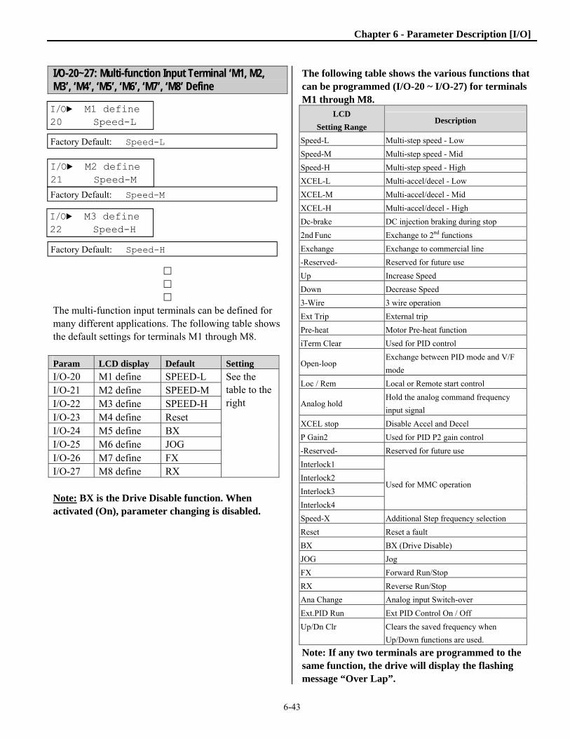
Chapter 6 - Parameter Description [I/O]
6-43
I/O-20~27: Multi-function Input Terminal ‘M1, M2, M3’, ‘M4’, ‘M5’, ‘M6’, ‘M7’, ‘M8’ Define
The multi-function input terminals can be defined for many different applications. The following table shows the default settings for terminals M1 through M8. Param LCD display Default Setting
I/O-20 M1 define SPEED-L See the table to the right
I/O-21 M2 define SPEED-M I/O-22 M3 define SPEED-H I/O-23 M4 define Reset I/O-24 M5 define BX I/O-25 M6 define JOG I/O-26 M7 define FX I/O-27 M8 define RX Note: BX is the Drive Disable function. When activated (On), parameter changing is disabled.
The following table shows the various functions that can be programmed (I/O-20 ~ I/O-27) for terminals M1 through M8.
LCD
Setting Range Description
Speed-L Multi-step speed - Low
Speed-M Multi-step speed - Mid
Speed-H Multi-step speed - High
XCEL-L Multi-accel/decel - Low
XCEL-M Multi-accel/decel - Mid
XCEL-H Multi-accel/decel - High
Dc-brake DC injection braking during stop
2nd Func Exchange to 2nd functions
Exchange Exchange to commercial line
-Reserved- Reserved for future use
Up Increase Speed
Down Decrease Speed
3-Wire 3 wire operation
Ext Trip External trip
Pre-heat Motor Pre-heat function
iTerm Clear Used for PID control
Open-loop Exchange between PID mode and V/F
mode
Loc / Rem Local or Remote start control
Analog hold Hold the analog command frequency
input signal
XCEL stop Disable Accel and Decel
P Gain2 Used for PID P2 gain control
-Reserved- Reserved for future use
Interlock1
Used for MMC operation Interlock2
Interlock3
Interlock4
Speed-X Additional Step frequency selection
Reset Reset a fault
BX BX (Drive Disable)
JOG Jog
FX Forward Run/Stop
RX Reverse Run/Stop
Ana Change Analog input Switch-over
Ext.PID Run Ext PID Control On / Off
Up/Dn Clr Clears the saved frequency when
Up/Down functions are used.
Note: If any two terminals are programmed to the same function, the drive will display the flashing message “Over Lap”.
I/O► M1 define 20 Speed-L
Factory Default: Speed-L
I/O► M2 define 21 Speed-M
Factory Default: Speed-M
I/O► M3 define 22 Speed-H
Factory Default: Speed-H

Chapter 6 - Parameter Description [I/O]
6-44
I/O-28: Terminal Input Status This parameter displays the input status of control terminals M1-M8. P4-P6 are for future use.
Input
Term
P6 P5 P4 M8 M7 M6 M5 M4 M3 M2 M1
10
bit
9
bit
8
bit
7
bit
6
bit
5
bit
4
bit
3
bit
2
bit
1
bit
0
bit
OFF
status 0 0 0 0 0 0 0 0 0 0 0
ON
status 1 1 1 1 1 1 1 1 1 1 1
I/O-29: Multi-function input terminal filter time constant Debounces and sets the responsiveness of input terminals M1-M8. Increasing the filter time is effective when noise level is high. Increasing this parameter will make response time slower and decreasing it will make response faster. Note: Set the parameter higher than 100msec when attempting Inverter-Commercial Line Exchange operation. This will prevent chattering during the transition.
I/O-30: Jog Frequency This parameter sets the jog frequency. I/O-31~42: Step Frequency 4, 5, 6, 7, 8, 9, 10, 11, 12, 13, 14, 15
□
□
□
[Speed-L, Speed-M, Speed-H, Speed-X] By setting M1, M2, M3 terminals to ‘Speed-L’, ‘Speed-M’ and ‘Speed-H’ respectively, the drive can operate at seven preset frequencies set in DRV-21 ~ DRV-23 and I/O-31 ~ I/O-34. An additional terminal M(x) can be set to Speed X to allow eight additional preset frequencies (total of 15) using parameters I/O-35 ~ I/O-42. The step frequencies are determined by the combination of M1, M2, M3 and Mx terminals as shown in the following table.
I/O► Step freq-4 31 40.00 Hz
Factory Default: 40.00 Hz
I/O► Step freq-5 32 50.00 Hz
Factory Default: 50.00 Hz
I/O► In status 28 00000000000
Factory Default: 00000000000
I/O► Jog freq 30 10.00 Hz
Factory Default: 10.00 Hz
I/O► Ti Filt Num 29 15 ms
Factory Default: 15 ms

Chapter 6 - Parameter Description [I/O]
6-45
Parametr
Step Speed
Frequency Spd-
X
Spd-
H
Spd-
M
Spd-
L
J
O
G
DRV-00
(Note 1)
S. Freq-0
(Spd-0) 0 0 0 0 0
I/O-30
(Note 2)
Jog Freq X X X X 1
DRV-21 S. Freq-1
(Spd 1) 0 0 0 1 0
DRV-22 S. Freq-2
(Spd 2) 0 0 1 0 0
DRV-23 S. Freq-3
(Spd-3) 0 0 1 1 0
I/O-31 S. Freq-4
(Spd-4) 0 1 0 0 0
I/O-32 S. Freq-5
(Spd-5) 0 1 0 1 0
I/O-33 S. Freq-6
(Spd-6) 0 1 1 0 0
I/O-34 S. Freq-7
(Spd-7) 0 1 1 1 0
I/O-35 S. Freq-8
(Spd-8) 1 0 0 0 0
I/O-36 S. Freq-9
(Spd-9) 1 0 0 1 0
I/O-37 S. Freq-10
(Spd-10) 1 0 1 0 0
I/O-38 S. Freq-11
(Spd-11) 1 0 1 1 0
I/O-39 S. Freq-12
(Spd-12) 1 1 0 0 0
I/O-40 S. Freq-13
(Spd-13) 1 1 0 1 0
I/O-41 S. Freq-14
(Spd-14) 1 1 1 0 0
I/O-42 S. Freq-15
(Spd-15) 1 1 1 1 0
0: OFF, 1: ON, X: Ignored (Jog takes priority)
Speed-L: Lowest bit in Multi-Step speed input
Speed-M: Middle bit in Multi-Step speed input
Speed-H: High bit in Multi-Step speed input
Speed-X: Highest bit in Multi-Step speed input
Note 1: ‘Speed 0’ is based on the Freq. Ref. source set in
DRV-04.
Note 2: If the ‘Jog’ terminal is ON, drive operates at Jog
frequency regardless of other terminal inputs.
DRV-04 Data DRV-00 Speed 0 Freq source
Keypad-1 Digital Freq Ref Keypad Keypad-2 Digital Freq Ref Keypad V1 Analog Freq Ref. Terminal V1S Analog Freq Ref. Terminal I Analog Freq Ref. Terminal V1+I Analog Freq Ref. Terminal Pulse Pulse Freq Ref. Terminal Int. 485 Communication Terminal
Ext. PID Ext. PID Freq Ref. Keypad or Terminal
Setting example (Seven Preset Speeds) M1=Speed-L, M2=Speed-M, M3=Speed-H, M4=Jog M5=BX, M7=FX, M8=RX Step speeds are set in parameters DRV-21~23 and I/O-31~34.
Multi-Step Frequency Operation
Speed-L ON ON
Speed-M ON ON
Speed-H ON
JOG ON
FX ON
RX ON
ON ON
Step 0
Step 1
Step 2
Step 3
Step 4
Step 5
Step 6
Step 7
Jog

Chapter 6 - Parameter Description [I/O]
6-46
I/O-50~63: 1st~7th Accel/Decel Time
Description of Digital I/O Selections [XCEL-L, XCEL-M, XCEL-H] By setting M1, M2 and M3 terminals to ‘XCEL-L’, ‘XCEL-M’ and ‘XCEL-H’ respectively, up to eight different Accel and Decel times can be used. The Accel/Decel times are set in DRV-01, DRV-02 and I/O-50 ~ I/O-63. The Accel/Decel time is determined by the combination of M1, M2 and M3 terminals as shown in the following table.
Parameter
Accel/Decel
Time
XCEL-
H
(M3)
XCEL-
M
(M2)
XCEL-
L
(M1)
DRV-01 Accel Time-0 0 0 0
DRV-02 Decel Time-0
I/O-50 Accel Time-1 0 0 1
I/O-51 Decel Time-1
I/O-52 Accel Time-2 0 1 0
I/O-53 Decel Time-2
I/O-54 Accel Time-3 0 1 1
I/O-55 Decel Time-3
I/O-56 Accel Time-4 1 0 0
I/O-57 Decel Time-4
I/O-58 Accel Time-5 1 0 1
I/O-59 Decel Time-5
I/O-60 Accel Time-6 1 1 0
I/O-61 Decel Time-6
I/O-62 Accel Time-7 1 1 1
I/O-63 Decel Time-7
0: OFF, 1: ON
Multi-Accel/Decel Time Operation [Dc-brake] DC Injection Braking can be activated by configuring one of the multi-function input terminals (M1-M8) to ‘Dc-brake’. The preset DC-start value in FUN-22 is applied to the motor only when stopped. To activate the DC Injection Braking, close the contact of the assigned terminal while the drive is stopping. CAUTION – DC is applied to the motor the entire time the input is closed. While DC Brake is activated, the “FWD” and “REV” LED’s will blink. [2nd function] This function provides a second set of motor parameters when a different motor is connected to the drive. See APP 20~29 for details. Drive must be stopped to activate the second set of motor parameters.
I/O► Acc time-1 50 20.0 sec
Factory Default: 20.0 sec
I/O► Dec time-1 51 20.0 sec
Factory Default: 20.0 sec
Output Frequency
M1 ON
Time
Time
M2 ON Time
M3 ON Time
FX ON Time
ON ON ON
ON
Ref.Freq.
Time 0
Time 1
Time 2
Time 3
Time 4
Time 5
Time 6
Time 7

Chapter 6 - Parameter Description [I/O]
6-47
[EXCHANGE] Exchange is used to switch the motor from the drive output to line (commercial) power or from line to drive output. To bypass the motor to commercial line, set the ‘Exchange’ function in one of the multi-function input terminal in I/O-20~27 and set one multi-function output terminal (Ax-Cx) to ‘INV line’, and another to ‘COMM line’ with parameters I/O-76~79. Note: Speed search function (AFN-22) is activated automatically during exchanging operation, enabling smooth exchange. The following 3 settings should be made to activate the exchange function: 1) Set one of the Multi-function input terminals (I/O-20~27) to “Exchange.” 2) Set one of the Multi-function Aux. Contact Output terminals to “INV line.” 3) Set another Multi-function Aux. Contact Output terminal to “COMM line.” Note: I/O-29 [Filtering Time Constant for Multi-function Input Terminals] must be set to more than 100 [msec] to prevent chattering and resulting problems during the exchange.
Exchanging Sequence
Speed
‘Exchange’-CM
FX-CM ON
Time
Time
ON Time
AX-CX‘COMM line’ ON Time
M1 ON Time
M2 ON Time
ON
t1 t2
Inverter Operation
Inverter Operation
Commercial Line Oper.
t1, t2: 500msec (interlock time)
‘INV line’ ON Time
ON
Output Freq.

Chapter 6 - Parameter Description [I/O]
6-48
[Up, Down] The speed of the drive can be controlled using two multi-function input terminals. Externally connected momentary switches can increase (Up) or decrease (Down) the speed of the drive. Setting limit is Maximum frequency. See also FUN-75 and FUN-76 for saving Up/Down speeds.
Up/Down Operation [3-Wire] This function is used for 3-wire start/stop control. This function is used with a momentary push button (NO) to start and a momentary (NC) pushbutton for stop.
Wiring for 3-Wire Operation, Mx set to ‘3-Wire’
[Ext Trip] This is a normally open contact input. When a terminal set to ‘Ext Trip’ is ON, the drive cuts off its output and displays an external fault. This can be used as an external latch trip or used when an external motor overload protection relay is used. The logic is programmable in I/O-95 [Normal Open/Normal Close select]. [Pre-Heat] When a digital input, programmed to Pre-Heat is activated, the drive applies low levels of DC current to the motor. See FUN-10, 11 and 12. [iTerm Clear] This function is used for PID control. When this terminal is ON, the accumulated value of the integrator used by the I-Gain is set to ‘0’. Refer to the PID Control Block Diagram for more information. [Open-loop] This function is used to switch the control mode of the drive from PID mode to V/F mode (Open Loop). When a digital input, programmed to Open Loop is activated, DRV-03 [Drive Mode] and DRV-04 [Frequency Mode] control the drive. Note: This function is only used when the drive is stopped. [LOC / REM] When the Local / Remote input is activated (ON), the Remote parameters, DRV-91 and DRV-92 control the drive command and drive frequency. When the input is deactivated (OFF), the Local parameters DRV-03 and DRV-04 control the drive command and drive frequency.
M1-CM‘Up’ ON
Output Frequency
Time
Time
M2-CM‘Down’
ON Time
FX-CM ON Time
Freq.Max.
Mx-CM ON
Output Frequency
Time
Time
FX-CM ON Time
RX-CM ON Time
Freq.Max.
Freq.max.
Forward Reverse 3-Wire
Stop
M7 M8 Mx CM

Chapter 6 - Parameter Description [I/O]
6-49
[Analog hold] When there is an analog input signal for frequency reference and ‘Analog hold’ terminal is ON, drive fixes its output frequency regardless of the frequency reference. When the terminal is OFF, the actual frequency reference will be applied. This function is useful when a system requires constant speed after acceleration or when the freq reference is not necessary to be changed.
Analog Hold Operation [XCEL stop] Drive stops accelerating and decelerating when this terminal is ON. [P Gain 2] This function is used to change P-Gain during PID operation. When this terminal is ON, PID controller changes P-Gain to PID P2-Gain. Refer to PID Control Block Diagram.
[Interlock 1, 2, 3, 4] This function is used for MMC operation. When MMC is selected in APP-01 and interlock is set, M1, M2, M3 and M4 are automatically assigned for Interlock function. Therefore, these terminals cannot be used for setting other functions when interlock is active. Use M5, M6, M7, and M8 for other function setting. Refer to MMC operation.
[Reset] This function is used as a fault reset terminal when ON. It requires a momentary contact closure for fault reset. [BX] This function is used to disable the drive output when ON. Can be used as an E-Stop function, requires a manual reset. The logic is programmable in I/O-95 [Normal Open/Normal Close select]. [JOG] This function is used for Jog operation when ON. Jog speed is set with I/O-30. [FX/RX] These functions are used to issue Forward/Reverse run commands. [Ana Change] The drive changes its frequency reference source from V1 to I when ON. Ex) When DRV-04 is set to V1+I operation, V1 is the default setting and is changed to I operation when the terminal is turned ON. [Ext.PID Run] External PID controller begins operation when the defined terminal is turned ON. This can be operated regardless of the drive reference command or used in conjunction with internal PID operation. Refer to External PID operation for details. [Up/Dn Clr] This function is used to reset (clear) the saved frequency when FUN-75, Up/Down Save Mode is set to “yes”.
M1-CM‘Analog hold’
Analog frequency reference
Time
ON Time
Reference Frequency
Output Frequency

Chapter 6 - Parameter Description [I/O]
6-50
I/O-70~73: S0, S1 terminal select Analog output signals from the S0, S1 terminals can be used to monitor/display the drive Output Frequency, Current, Voltage, DC link voltage, External PID and/or Power (Watts). The output voltage range is 0V to 10V. Parameters I/O-71, 73 are used to adjust the S0, S1 output gain value. [Frequency] The S0/S1 terminal provides an analog output corresponding to output frequency. The output value is determined by the following formula: S0/S1 Output Voltage = (Output freq. / Max. freq.) × 10V × (IO-71 or 73) / 100. [Current] The S0/S1 terminal provides an analog output corresponding to current. The output value is determined by the following formula: S0/S1 Output Voltage = (Output current / Rated current) × 10V × (IO-71 or 73) / 100. [Voltage] The S0/S1 terminal provides an analog output corresponding to the drives output voltage. The output value is determined by the following formula: S0/S1 Output Voltage = (Output voltage / Max. output voltage) × 10V × (IO-71 or 73) / 100.
[DC link vtg] The S0/S1 terminal provides an analog output corresponding to the dc link voltage. The output value is determined by the following formula: S0/S1 Output Voltage = (DC link voltage/Max. DC link voltage) × 10V × (IO-71 or 73) / 100. Note: Maximum DC Link Voltage for 230V class is 410V and for 460V class 820V. [Ext.PID Out] The S0/S1 terminal provides an analog output corresponding to the External PID output. The output value is determined by, S0/S1 output voltage = (External PID output/10000) x 10V x S0, S1 output gain (I/O-71 or 73) / 100. [Watts] The S0/S1 terminal provides an analog output corresponding to output power. The output value is determined by the following formula: S0/S1 Output Voltage = (Output Power / 200% Drive Rating) × 10V × (IO-71 or 73) / 100. Note: Power calculation is effective power, √3 x V x I. Note: Output voltage of 10V is based on 200% drive rated power.
Output Power
100%
I/O► S0 mode 70 Frequency
Factory Default: Frequency
I/O► S0 adjust 71 100 %
Factory Default: 100 %
I/O► S1 mode 72 Voltage
Factory Default: Voltage
I/O► S1 adjust 73 100 %
Factory Default: 100 %
S0/S1 -5G
10 V
0 % 100 %
Gain*10 V
Output V
S0/S1 -5G
10 V
0 % 200 %
Gain*10 V
Output V

Chapter 6 - Parameter Description [I/O]
6-51
I/O-74: FDT (Frequency Detection) Level I/O-75: FDT Bandwidth These functions are used with I/O-76-79 [Multi-function Auxiliary Contact Output] when set to FDT-#. See [FDT-#] in I/O-76~79. I/O-76~79: Multi-function Auxiliary Contact Output mode 1, 2, 3, 4 define (Ax-Cx) Terminals A1-C1, A2-C2, A3-C3, and A4-C4 are Form A relays that are programmable to the functions listed in the table below. The auxiliary contact will close when the defined condition has occurred. Each terminal can be programmed to a different function. In the following descriptions AX-CX is used to represent any one of the relay output terminals.
LCD
Setting Range Description
None None
FDT-1 Reference frequency detection
level – (At speed)
FDT-2 Specific frequency level
detection
FDT-3 Frequency detection bandwidth
FDT-4 Frequency detection 1 with
contact closure
FDT-5 Frequency detection 2 with
contact closure
OL Overload detection
IOL Inverter overload detection
Stall Stalling
LCD
Setting Range Description
OV Over voltage detection
LV Low voltage detection
OH Inverter overheat detection
Lost Command Lost command detection
Run Inverter running detection
Stop Inverter stop detection
Steady Steady speed detection
INV line Exchange signal outputs
COMM line
Search Speed search mode detection
Ready Drive ready detection
MMC Used for MMC operation
OH Warn Over Heat Warning–See FUN-
80, Over Heat Warning Level
FAN Signal Closes when Fan On-See I/O-84
RMT Status Closes when in Remote Control
[FDT-1] When the output frequency reaches the reference frequency (target frequency), AX-CX terminal is CLOSED. Detecting Condition: Value (Ref. Freq-Output Freq)<=
Freq Detection Bandwidth (I/O-75)/2
AX-CX configured as ‘FDT-1’
*AX: A1~A4, CX: C1~C4
I/O► FDT freq 74 30.00 Hz
Factory Default: 30.00 Hz
I/O► FDT band 75 10.00 Hz
Factory Default: 10.00 Hz
I/O► Aux mode 1 76 None
Factory Default: None
AX-CX
CLOSED
Output Frequency
Time
Time
I/O-75/ 2
Ref. freq

Chapter 6 - Parameter Description [I/O]
6-52
[FDT-2] AX-CX is CLOSED when the reference frequency is in I/O-75 [FDT Bandwidth] centered on I/O-74 [FDT Frequency], and the output frequency reaches I/O-75 centered on I/O-74. Detecting Condition: FDT-1 condition & (Value (Output
Freq- Freq Detection)<= Freq Detection Bandwidth (I/O-
75)/2)
AX-CX configured as ‘FDT-2’ [FDT-3] AX-CX is CLOSED when the output frequency reaches the band centered on the FDT frequency. The output is OPENED when the output frequency goes outside the FDT bandwidth centered on the FDT frequency. Detecting Condition: Value (Freq Detection (I/O-74)-
Output Freq)<= Freq Detection Bandwidth (I/O-75)/2
AX-CX configured as ‘FDT-3’
[FDT-4] AX-CX is CLOSED when the output frequency reaches the FDT frequency. The output is OPENED when the output frequency goes below the FDT bandwidth centered on the FDT frequency. Detecting Condition:
During Accel: Output freq >= Freq Detection
During Decel: Output freq > (Freq Detection (I/O-74) -
Freq Detection Bandwidth (I/O-75)/2)
AX-CX configured as ‘FDT-4’ [FDT-5] This is the inverted output of [FDT-4]. Detecting Condition:
During Accel: Output freq <= Freq Detection
During Decel: Output freq < (Freq Detection (I/O-74) -
Freq Detection Bandwidth (I/O-75)/2)
AX-CX configured as ‘FDT-5’
AX-CX CLOSED
Output Frequency
Time
Time
I/O-75 / 2I/O-74
AX-CX ON
Output Frequency
Time
Time
I/O-75/ 2
ON
I/O-74
AX-CX
Output Frequency
Time
Time
I/O-75 / 2
CLOSED
I/O-74
AX-CX
Output Frequency
Time
Time
I/O-75/ 2
ON
I/O-74
ON

Chapter 6 - Parameter Description [I/O]
6-53
[OL] AX-CX is CLOSED when the output current has reached the FUN-64 [Overload Warning Level] for the FUN-65 [Overload Warning Time].
AX-CX configured as ‘OL’ [IOL] AX-CX is CLOSED when the output current is above the 110% of the drives standard duty rated current for 36 seconds. If this situation is continued for one minute, the drive will cut off its output and displays ‘IOL’ (Inverter overload) Trip. See the nameplate for the rated inverter current. The IOL function has an Inverse Time (I²t) characteristic and provides an alarm (closes relay) at 60% (36 secs) of the one minute time period.
AX-CX configured as ‘IOL’
[Stall] AX-CX is CLOSED when the drive is in the stall prevention mode.
AX-CX configured as ‘Stall’
[OV] AX-CX is CLOSED when the DC link voltage is above the Over-voltage level.
AX-CX configured as ‘OV’
t1: FUN-65 [Overload Warning Time]
Output Current
Time
Time
FUN-64[OL level]
FUN-64[OL level]
AX-CX ON
t1 t1
Output Current
Time
Time
110% of RatedInverter
AX-CX ON
36sec
110% of RatedInverter
24sec
Output Current
Time
Output Frequency
Time
FUN-71[Stall Level]
FUN-71[Stall Level]
TimeCLOSED AX-CX
AX-CX ON
DC Link Voltage
Time
Time
OV Level: 390V DC 760V DC 980V DC

Chapter 6 - Parameter Description [I/O]
6-54
[LV] AX-CX is CLOSED when the DC link voltage is below the Low-voltage level.
AX-CX configured as ‘LV’ [OH] AX-CX is CLOSED when the heat sink of the drive is above the reference level. [Lost Command] AX-CX is CLOSED when frequency reference is lost. [Run] AX-CX is CLOSED when the drive is running (above the start frequency, FUN-32). It does not close a 0 Hz. [Stop] AX-CX is CLOSED when the drive is stopped. [Steady] AX-CX is CLOSED when the drive is running at a constant speed. [INV line, COMM line] These functions are used in conjunction with the ‘Exchange’ function to transfer the output of the drive to commercial line power. The following three conditions should be set: 1) Define one of the Multi-function input terminals to “Exchange”. 2) Define one of the Multi-function output terminals to “INV line”. 3) Define one of the Multi-function output terminals to “COMM line”.
AX-CX configured as ‘COMM line’ and
‘INV line’. Mx terminal configured as ‘Exchange’. [Ssearch] AX-CX is CLOSED when the drive is speed searching. [Ready] AX-CX is CLOSED when the drive is ready to receive a start command and is ready to run. [MMC] Automatically set to ‘MMC’ when ‘MMC’ is selected in APP-01. See also APP-40 ~ APP-72. [OH Warn] AX-CX is closed when drive temperature reaches the percentage set in FUN-80, Over Heat Warning Level. [FAN Signal] AX-CX closes when fans are running. See I/O-84, Fan Control. [RMT Status] AX-CX closes when drive is in Remote Control.
AX-CX ON
DC Link Voltage
Time
Time
LV Level 200V DC 400V DC 500V DC
Mx terminal
‘Exchange’
FX-CM ON
Output Frequency
Time
Time
ON Time
‘COMM line’ ON Time
ON Time
ON
t1 t2
Inverter Drive
Inverter Drive
Commercial Line Drive
t1, t2: 500msec (interlock time)
Speed Search
‘INV line’

Chapter 6 - Parameter Description [I/O]
6-55
I/O-80: Fault Output Relay (3A, 3B, 3C) This parameter determines how the fault relay will operate during a fault condition and during low voltage conditions.
Bit Setting Display Description
Bit 1
(LV)
0 000
Fault output relay does
not operate at ‘Low
voltage’ trip.
1 001
Fault output relay
operates at ‘Low voltage’
trip.
Bit 2
(Trip)
0 000 Fault output relay does
not operate at any fault.
1 010
Fault output relay
operates at any fault
except ‘Low voltage’ and
‘BX’ (inverter disable)
fault.
Bit 3
(Retry)
0 000
Fault output relay does
not operate regardless of
the retry number.
1 100
Fault output relay
operates when the retry
number set in AFN-26
decreases to 0 by faults.
Disabled while Auto retry
is ON.
When several faults occurred at the same time, Bit 1 has the
first priority. (Active order: Bit 1->Bit 2->bit3)
I/O-81: Terminal Output Status This parameter displays the condition of each of the outputs. This is useful in monitoring the status of the terminals.
Output
Terminals
3A-
3C Q3 Q2 Q1
AUX
4
AUX
3
AUX
2
AUX
1
Bit 7 Bit 6 Bit 5 Bit 4 Bit 3 Bit 2 Bit 1 Bit 0
OFF status 0 0 0 0 0 0 0 0
ON status 1 1 1 1 1 1 1 1
I/O-82, 83: Fault Relay On/Off Delay Time The Fault relay ON time is delayed for the time set in I/O-82 and its OFF time is delayed by the amount of time in I/O-83.
Fault Relay Delay Times
I/O► Out status 81 00000000
Factory Default: 00000000
I/O► Relay mode 80 010
Factory Default: 010
Relay input
Relay output
On Delay Time Off Delay Time
I/O► Relay On 82 0.0 sec
Factory Default: 0.0 sec
I/O► Relay Off 83 0.0 sec
Factory Default: 0.0 sec
----Not Used----

Chapter 6 - Parameter Description [I/O]
6-56
I/O-84: Cooling Fan Control Selection This parameter determines the operating condition of the drives cooling fans.
I/O-84 Setting Range
Description
PowerOn Fan Fan is ON when power is ON. Run Fan Fan is ON when the drive runs
(outputs frequency). Temper Fan Fan is ON when the drive
temp exceeds the preset value in I/O-85.
Note: I/O-84, 85 are only programmable for drives 50HP and higher. I/O-85: Fan Temperature When I/O-84 is set to Temper Fan, this parameter sets the temperature at which the fans turn on. Range 0 – 70 degrees Celsius Note: I/O-84, 85 are only programmable for drives 50HP and higher.
I/O-86: User Unit selection (PI Mode only) I/O-87: Units Maximum Value
When PID operation is selected in APP-02, APP-80, or APP-62, the drive displays units in PSI, rather than speed (Hz.). The user can chose units to display listed in the table below.
I/O-86 Setting Range
Description
Percent Flow rate, pressure and temperature are displayed in [%].
Bar Pressure is displayed in [Bar].
mBar Pressure is displayed in [mBar].
kPa Pressure is displayed in [kPa]. Pa Pressure is displayed in [Pa]. Psi Pressure is displayed in [Psi].
Scaling: I/O-87, Unit Maximum Value is used to set the maximum value of the units selected in I/O-86. If PSI (I/O-86) is selected and sensor maximum pressure is 300 PSI, enter 300 PSI. When “I” is selected as the feedback (APP-06 default), scaling of the “I” is done with parameters I/O-87, Max. Pressure along with parameter APP-31 “meter I max”. These two parameters set the maximum pressure at the maximum feedback signal (default is 20mA). See table below. Scaling of feedback signal “I”.
Param Factory setting Description
I/O-86 PSI Units select
I/O-87 100.0 PSI Max. Pressure
APP-06 I Feedback select
APP-31 20 mA Max. Feedback signal
at Max. Pressure
I/O►Fan Con. Sel 84
Factory Default: PowerOn_Fan
I/O► Unit Sel 86 Percent
Factory Default: Percent (PSI in PI Mode)
I/O Unit Max Val87 100.0%
Factory Default: 100.0 % (PSI in PI Mode)
I/O►Fan Temp 85 70

Chapter 6 - Parameter Description [I/O]
6-57
Likewise if “V1” is chosen as feedback (APP-06), parameter APP-32, “meter V max” is the maximum value of the feedback voltage (default is 10V) corresponding to the maximum PSI value, I/O-87. Scaling of feedback signal “V1”.
Param User setting Description
I/O-86 PSI Units select
I/O-87 100.0 PSI Max. Pressure
APP-06 V1 Feedback select
APP-32 10 V Max. Feedback signal
at Max. Pressure
Note: When APP-02, APP-80 or APP-62 are set to “No”, units in I/O-86 are not used, all parameters default to Speed [Hz]. I/O-90: Inverter Number I/O-91: Baud Rate I/O-92: COM Lost Cmd I/O-93: COM Time Out I/O-94: Delay Time I/O-90 [Inverter Number] sets the drives ID number for RS-485/Modbus communication. I/O-91 [Baud rate] sets the communication speed. Terminals C+ and C- are used for RS-485 communication.
I/O-92 [Com Lost command] determines the method of operation if the communication signal is lost. If lost, the drive will display LOR on the LCD display. The possible functions for I/O 92 are shown in the following table:
Setting Range Description
None Continuous operation after loss of
communication signal.
FreeRun
Drive cuts off its output after
determining loss of communication
signal.
Stop
Drive stops by its Decel pattern and
Decel time after determining loss of
communication signal.
I/O-93 [Communication time out] sets the delay time before the drive faults after the communication signal is lost. When lost, the drive will display LOR on the LCD display. I/O-94 setting is for communications using RS232-RS485 converters. It should be set properly according to RS232-RS485 converter specification.
I/O► COM Lost Cmd 92 None
Factory Default: None
I/O► COM Time Out 93 1.0 sec
Factory Default: 1.0 sec I/O► Inv No. 90 1
Factory Default: 1
I/O► Baud rate 91 9600 bps
Factory Default: 9600 bps I/O► Delay Time 94 5
Factory Default: 5 ms

Chapter 6 - Parameter Description [I/O]
6-58
I/O-95: Normal Open/ Normal Closed select The digital inputs, M1, M2, M3, M4, M5, M6, M7, and M8 can be programmed as a NO or a NC contact. If the terminal is programmed as NO, the input will have to be closed to activate the programmed function. If the terminal is programmed as NC, the input will have to be opened to activate the function.
Input
T/M
M8 M7 M6 M5 M4 M3 M2 M1
Bit
7
Bit
6
Bit
5
Bit
4
Bit
3
Bit
2
Bit
1
Bit
0
0: NO
1: NC 0/1 0/1 0/1 0/1 0/1 0/1 0/1 0/1
I/O-96: Input Checking Time This sets the amount of time the drive will wait to confirm a valid input signal on one of the digital inputs.
I/O-97: Overheat Trip Selection I/O-98: Motor Trip Temperature Setting Range 0 – 255 °C
The drive can monitor motor temperature by connecting a motor thermistor (PTC/NTC) to terminals NT-5G (40 HP and below) or terminals ET-CM (50 HP and above). See Thermistor Specifications on the following page. Motor trip temperature is set with I/O-98. Motor temperature can be viewed at parameter FUN-56, Motor Temperature.
Param Bit set Function
I/O-97
2 1 0
1 Motor overheat trip
activation 0=Off, 1=On
1 -Reserved-
1
External temperature
sensor selection
0=NTC, 1=PTC
Note: Bit 1 is not used. Examples: Setting I/O-97 to 001 activates the motor overheat protection using an NTC sensor. Setting I/O-97 to 101 activates the motor overheat protection using a PTC sensor. In both cases, set motor trip temperature in I/O-98. The fault displayed when using this protection is “EXT. OHT”, External Over Heat fault. NOTE: Inverter Overheat protection is activated regardless of motor temp setting condition.
NOTE: Overheat protection can be monitored by setting one of the Aux Relays (I/O-76 ~ 79) to OH.
I/O► In No/NC Set 95 00000000
Factory Default: 00000000
I/O► In CheckTime 96 1 ms
Factory Default: 1 ms
ON (Speed-L)
Spd 0 Spd 0 Spd 0 Spd 0 Spd 7 Spd 7 Spd 7 Spd 2
BX
RX
Output freq [Hz]
Input checking time
ON
ON (FX)
ON (Speed-H)
ON (Speed-M)
ON
checking time checking time
I/O► OH Trip Sel 97 010
Factory Default: 010
I/O► MotTripTemp 98 110
Factory Default: 110 [C]

Chapter 6 - Parameter Description [I/O]
6-59
Specification of External PTC/NTC Thermistor
Sensor Resistance based on 25 C
Resistance by temperature Measurable Temp range
PTC 1K] (±5%) R(T)=[1+A*(Measured temp-25)+B *( Measured temp –25)2][K ] A=7.635X10⁻³, B=1.371 X10⁻⁵
0~125[C]
NTC 2.545K] (±5%) See the table below for NTC resistance by temperature. 0~150[C]
Note : Measurable temp range varies by thermal sensors. Select the sensor after checking the measurable temp range specification. NTC resistance according to temperature
Temp
[C]
R
[K] Temp
[C]
R
[K] Temp
[C]
R
[K] Temp
[C
R
[K] Temp
[C]
R
[K] Temp
[C]
R
[K] Temp
[C]
R
[K] 80 0.3562 90 0.2649 100 0.2002 110 0.1536 120 0.1195 130 0.0942 140 0.0752
81 0.3455 91 0.2574 101 0.1949 111 0.1497 121 0.1167 131 0.0921 141 0.0736
82 0.3353 92 0.2502 102 0.1897 112 0.1459 122 0.1139 132 0.0900 142 0.0720
83 0.3254 93 0.2432 103 0.1847 113 0.1423 123 0.1112 133 0.0880 143 0.0705
84 0.3158 94 0.2364 104 0.1798 114 0.1387 124 0.1085 134 0.0860 144 0.0690
85 0.3066 95 0.2299 105 0.1751 115 0.1353 125 0.1060 135 0.0841 145 0.0675
86 0.2976 96 0.2236 106 0.1705 116 0.1319 126 0.1035 136 0.0822 146 0.0661
87 0.2890 97 0.2174 107 0.1661 117 0.1287 127 0.1011 137 0.0804 147 0.0647
88 0.2807 98 0.2115 108 0.1618 118 0.1255 128 0.0987 138 0.0786 148 0.0633
89 0.2727 99 0.2058 109 0.1577 119 0.1225 129 0.0965 139 0.0769 149 0.0620
150 0.0608
Note: Use the external NTC having the specification shown above and adjust I/O-98 when there is a temperature difference between the drive and external sensor.

6-60
NOTES:

Chapter 6 - Parameter Description [APP]
6-61
6.5 Applicationgroup[APP] APP-00: Jump to Desired Parameter Jumping directly to any parameter can be accomplished by programming the desired parameter number. APP-01: Application Mode Selection This parameter sets the desired application mode.
LCD
Setting Range Description
None Application mode is not selected.
MMC
MMC (Multi-Motor Control) mode is
selected in application group. Related
parameters (APP-40~72) are
displayed. Relay parameters I/O-
76~79 are automatically set to
“MMC” for controlling multiple
motors via across the line starting. If
less than 4 auxiliary motors are
connected, the remaining relays can
be used for other functions.
Caution: When APP-01 is set to “MMC”, then set back to “None”, parameters I/O-76 ~ 79 need to be programmed to their desired function. They do not automatically return to their previous setting.
APP-02: PID Operation Selection This function can be used for process control. It can control flow, pressure, temperature or other process variables. To use this function, set APP-02 [proc PI mode] to “Yes”. PID control detects the amount of feedback from a sensor and compares it with the target value. If the values differ, this function produces an output to eliminate the deviation. In other words, this control matches the target value with the feedback amount. For HVAC or Pump applications, the PID control can be used to adjust the actual output by comparing a feedback signal with a ‘Set-point’ given to the drive. This ‘Set-point’ can be in the form of Speed, Temperature, Pressure, Flow, Level, etc. The ‘Set-point’ can be entered via the keypad or via the analog input terminals. See APP-04 and APP-05. The feedback signal is provided externally to the drive via the analog input terminals. The drive compares the signals to calculate ‘total-error’ which is reflected in the drive's output. Note: PID control can be bypassed to manual operation temporarily by defining one of the multifunction input terminals (M1~M8) to “Open-loop”. The drive will change to manual operation from PID control when this terminal is ON, and change back to PID control when this terminal is OFF. [P Control] The P gain is the proportional part of the feedback loop. The higher the P value, the faster the drive will respond to process error. When P control is used alone, the system could become unstable. The I Control parameter should also be used. [I Control] The I Control is the integral part of the feedback loop. This is used to compensate the steady state error by accumulating them. Using this control alone makes the system unstable. The P control should also be used.
APP► Proc PI mode 02 No
Factory Default: No
APP► Jump code 00 1
Factory Default: 1
APP► App. mode 01 None
Factory Default: None

Chapter 6 - Parameter Description [APP]
6-62
[PI control] This control is stable in many systems. If “D control” is added, it becomes the 3rd order system. In some systems this may lead to system instability. [D Control] The D control is the derivative part of the feedback loop. Its primary purpose is to remove “hunting” in the control. The D control typically is more complicated to implement, but will result in a more stable system. This control does not affect the steady state error directly, but increases the system gain because it has an attenuation effect on the system. As a result, the differential control component has an effect on decreasing the steady state error. Since the D control operates on the error signal, it cannot be used alone. Always use it with the P control or PI control. Parameter setting example for PID operation
① Set APP-02 [PID operation selection] to “Yes.”
② Select the set-point source if different from keypad
in APP-04~05 (Aux. Ref. Signal). Refer to the following PID block diagram. Note: When APP-04 is set to “No,” DRV-04 [Freq Mode] becomes PID set point source. The default setting for DRV-04 is Keypad-1. Program the set point via the keypad at the main screen (DRV-00). If APP-04 is set to “Yes”, the selection set in APP-05 becomes PID set point source.
③ Set APP-06 [PID feedback selection] to I, V1 or
Pulse.
④ Select the desired units (default PSI) of the
process signals in I/O-86 [User unit selection]. This changes the units of the parameters related to the process (Target, Set Point, Feedback). They can be set to Percent, Bar, mBar, kPa, Pa, or PSI.
⑤ Select the maximum value of the sensor (units) in
I/O-87.
⑥ Select the maximum value of the feedback signal
in APP-31 (default 20 mA for “I”), APP-32 (default 10V for “V1”) or APP-33 (default 100kHz for “P”).
⑦ Select frequency limits of the drive output (if
required) with APP-10 and APP-11.
⑧ Select the polarity of the PID output with APP-15.
“No” is direct (normal) Feedback increase, Speed decrease. “Yes” is indirect (inverse) Feedback increase, Speed increase.
⑨ Adjust P and I gains (APP-07 and APP-08) as
necessary to obtain stable operation.
⑩ Viewable parameters are:
DRV-15 TAR 0.00 Hz
OUT 0.00 Hz
DRV-16 REF 0.00 PSI (Units per I/O-86)
FBK 0.00 PSI
DRV-18 R 0.0 Hz T 0.0 Hz
F 0.0 Hz O 0.0 Hz
Open Loop function: To disable PID control, program one of the multi-function input terminals (I/O-20 through 27) to the “Open loop” function. In Open Loop Mode, parameter DRV-04 will be the source of the drives speed reference. To change to another source for speed reference in Open Loop, use the Loc/Rem function. See I/O-20 ~ I/O-27, Loc/Rem function. Note: The accumulated integrator value used by I-Gain can be set to ‘0’ by setting a multi-function input terminal (M1 ~ M8) to ‘iTerm Clear’ in I/O-20 ~ I/O-27. Note: The P-Gain 2 can be selected for PID controller by setting a multi-function input (I/O-20 ~ I/O-27) to ‘P Gain 2’.

Chapter 6 - Parameter Description [APP]
6-63
PID
F/B
Sel
ecti
on
Acc
el/D
ecel
wT
arF
req
DR
V-1
4
Tar
get
Fre
q.
AP
P-
02
pro
c P
I m
od
e
PID
Kf
Lim
it
AP
P-1
0
PID
Hig
h L
imit
Fre
q.
pro
c P
I d
is
AP
P-1
2
Ga
in
AP
P-1
1
PID
Lo
w L
imit
Fre
q.
I/O
-20~
27
Mu
lti-
fun
ctio
n I
np
ut
Ter
min
al S
etti
ng
(M1~
M8)
PID
Ou
tpu
tS
cale
PID
F G
ain
: F
eed
Fo
war
d
DR
V-0
4
PID
Au
x R
ef S
etti
ng
Fre
q
AP
P-0
3
AP
P-0
4
Au
x R
ef M
od
e
Key
pad
-1
Key
pad
-2
V1
V1S I
V1+
I
Pu
lse
Int.
485
Ext
. P
ID
Au
x R
ef S
el
0 1 2 3 4 5 6 7 8
Jog Freq
Up Down Freq
Key
pad
-1
Key
pad
-2
V1
V1S I
V1+
I
Pu
lse
Int.
485
Ext
. P
ID
Fre
q M
od
e
0 1 2 3 4 5 6 7 8
V1I
Pu
lse
PID
F/B
0 1 2
AP
P-0
5
I/O
-20~
27M
ult
i-fu
nct
ion
In
pu
tT
erm
inal
Set
tin
g(M
1~M
8)
Ste
p F
req
-1
Ste
p F
req
-2
Ste
p F
req
-3
Ste
p F
req
-13
Ste
p F
req
-14
Ste
p F
req
-15
Sp
eed
-L,
-M,-
H,-
X
AP
P-0
6
Inve
rter
Ref
.F
req
Set
tin
g
PID
Blo
ck D
iagr
am

Chapter 6 - Parameter Description [APP]
6-64
In general, the PID output becomes the drive’s “Target Freq”. In this case, PID is controlling the whole system and the PID output becomes the target freq of the system and the drive is operating according to Accel/Decel Time. PID control sampling time is 10msec.
APP-07
APP-08
APP-09
PID P gain
PID I gain
PID D gain
KP
KI
KD
0
I/O-20~27
Multi-function inputterminal setting
(M1~M8)
iTerm Clear
KP 2K
APP-13 PID P2 gain
P Gain2
APP-14 PID P gain scale
PID
Target Freq.Deviation

Chapter 6 – Parameter Description [APP]
6-65
PID Wiring Example Keypad as Set point Feed Back as I (4-20mA)
Power Supply
PUMP
PID Control Selection
U
V W
R(L1) S(L2)
T(L3)
M7 FWD Run/Stop
M8 REV Run/Stop
M1 (Setting: Open-loop)
CM Common Terminal
IM
V+
V1
I Feed back Reference
5G V+, V1, I Common
24V Power Supply
User supplied DC Power
(OUT) (COM) (24V)
Feedback (4~20mA)
DRV-04 Keypad DRV-00 Set Point (program) APP-06 I (4-20mA) Feedback I/O-26 FX (M7 Fwd Run/Stop) I/O-27 RX (M8 as Rev Run/Stop) I/O-20 Open Loop (M1 to disable PI Control)
G

Chapter 6 - Parameter Description [APP]
6-66
APP-03: PID F Gain APP-04: PID Aux. Reference Mode Selection APP-05: PID Aux. Reference Selection This parameter sets F Gain for use in Feed Forward control. When it is set to 100%, the responsiveness (%) of output F gain from the controller reference value is 100%. Use when fast response is needed. Caution: Control System output may become unstable if this value is set too high. This parameter is not typically required for most PID systems. This parameter selects PID Aux Ref. Input Enable/Disable. See PID Block Diagram for details. When this parameter is set to “No”, the drive uses the source set in DRV-04 as its set point (reference). If this value is set to “Yes”, the drive will use the source set in APP-05 as its set point (reference). This parameter sets the source of Aux reference (set point) signal.
APP-06: PID Feedback Signal Selection APP-07: P Gain for PID Control APP-08: I Time for PID Control APP-09: D Time for PID Control This parameter determines which input will be the feedback signal for the PID loop. The default is set to the "I" terminal, but can be changed to the “V1”, “V1S”, or Pulse input terminals. This parameter sets the proportional gain of the PID controller. When P-Gain is set at 100% and I-Time at 0.0 second, the PID controller output is 100% for 100% error value. When P-Gain is set to 50% and I-Time to 0.0 sec, the PID controller output becomes 50% for 100% error value. This parameter sets the integral gain of the PID controller. This is the time the PID controller takes to output 100% for 100% error value. For example, when it is set to 30 sec, it takes 30 sec. for the PID controller to output 100% for 100% error value. 100% error means that the feedback value is 0 as compared to the preset reference value (setpoint). This parameter set the differential gain of the PID controller.
APP► PID F/B 06 I
Factory Default: I
APP► PID P-gain 07 1.0 %
Factory Default: 1.0 %
APP► PID I-time 08 10.0 sec
Factory Default: 10.0 sec
APP► PID D-time 09 0.0 ms
Factory Default: 0.0 ms
APP► PID F-Gain 03 0.0 %
Factory Default: 0.0%
APP►Aux Ref Mode 04 No
Factory Default: No
APP► Aux Ref Sel 05 V1
Factory Default: V1

Chapter 6 – Parameter Description [APP]
6-67
APP-10: High Limit Frequency for PID Control APP-11: Low Limit Frequency for PID Control This is the upper limit frequency at which the output frequency is limited during PID control. This is the lower limit frequency at which the output frequency is limited during PID control. APP-12: PID Output Scale APP-13: PID P2 Gain APP-14: P Gain Scale This parameter sets the scale of PID controller output. This parameter sets the second P-Gain for PID control. This parameter sets the conversion scale of P-Gain and P2-Gain.
APP-15: PID Output Inversion Parameter APP–15 [Output inversion] sets the PID controller’s output polarity. The output can be direct (No) or inverted (Yes). Note: Most applications require (No), this means as the pressure (or process variable) rises in the system, the speed will fall. If this parameters is set to (Yes), the speed will increase if the pressure (or process variable) increases. APP-17: PID Feedback U Adjustment This feature can be useful for fan and pumps application. It converts the linear pattern of a feedback sensor to the squared pattern without any additional settings.
APP► PID limit-H 10 60.00 Hz
Factory Default: 60.00 Hz
APP► PID limit-L 11 0.50 Hz
Factory Default: 0.50 Hz
APP►PID Out Scale 12 100.0 %
Factory Default: 100.0 %
APP► PID P2-gain 13 100.0 %
Factory Default: 100.0 %
APP►P-gain Scale 14 100.0 %
Factory Default: 100.0 %
APP► PID U Fbk 17 No
Factory Default: NO
APP► PID Out Inv. 15 No
Factory Default: No

Chapter 6 - Parameter Description [APP]
6-68
APP-20 ~ APP-29: 2nd Functions
The purpose of these parameters is to provide the user with a second set of motor parameters. This can be useful on test stands with different motors or where a user will be testing different types of applications using two different motors. These parameters are displayed only when one of the multifunction inputs in parameters I/O-20 to I/O-27 is set to ‘2nd func’. Contact closure to the input activates the 2nd Function parameters. Drive must be stopped to activate the second set of parameters.
Description 1st Functions 2nd Functions
Acceleration time DRV-01
[Acc. time]
APP-20
[2nd Acc time]
Deceleration time DRV-02
[Dec. time]
APP-21
[2nd Dec time]
Base Frequency FUN-31
[Base freq]
APP-22
[2nd BaseFreq]
Volts/Hz mode FUN-40
[V/F Pattern]
APP-23
[2nd V/F]
Forward torque
boost
AFN-68
[Fwd Boost]
APP-24
[2nd F-boost]
Reverse torque
boost
AFN-69
[Rev Boost]
APP-25
[2nd R-boost]
Stall prevention
level
FUN-60
[Stall Level]
APP-26
[2nd Stall]
ETH level for 1
minute
DRV-07
[ETH 1min]
APP-27
[2nd ETH 1min]
ETH level for
continuous
DRV-08
[ETH cont]
APP-28
[2nd ETH cont]
Motor rated current DRV-05
[Rated-Curr]
APP-29
[2nd R-Curr]
APP-31: Meter I Max Value APP-32: Meter V1 Max Value APP-33: Meter P Max Value When PI Control is selected in APP-02, these parameters are used for scaling the maximum feedback signal level at the maximum sensor pressure set in I/O-87.
APP►2nd Acc time 20 5.0 sec
Factory Default: 5.0 sec
APP►2nd Dec time 21 10.0 sec
Factory Default: 10.0 sec
APP► meter V max 32 10.00 V
APP► meter I max 31 20.00 mA
APP► meter P max 33 100.0 kHz

Chapter 6 – Parameter Description [APP]
6-69
APP-40~APP-72: MMC Operation Control Multiple Motor Control [MMC]: The ‘PID’ control should be selected in APP-02 to use this function. One drive can control multiple motors. This function is often used when controlling the flow rate or pressure of fans or pumps. The built-in PI controller directly controls a drive connected motor after receiving process control feedback value and keeps the control value constant by adjusting the speed of the drive connected motor and connecting and removing auxiliary motors to and from the commercial line when needed. In the case that the flow rate or flow pressure is beyond or below the reference and the drive connected motor cannot achieve the desired set point by itself, auxiliary motors are automatically turned on or off. A maximum of four (Aux.1-4 output) auxiliary motors can be controlled. Each motors Starting and Stopping Frequency can be set to automatically run four auxiliary motors. Auto Change can be selected (APP-66) to automatically switch the order of the running motors for balancing motor run-time. Set to AUX_EXCH mode for automatic changing of auxiliary motors only and set to MAIN_EXCH mode for automatic changing of all motors including main motor. For MAIN_EXCH mode APP-67/68 should be set and external sequence (APP-66) should be configured. A malfunctioning motor can be skipped from running by programming the multi-function input terminals (M1, M2, M3, and M4) as Interlock1 Interlock4. If a programmed multi-function terminal (M1, M2, M3 and M4) is opened (tripped), the drive stops all running motors and restarts operation with only the normal motors and leaves the malfunctioning motor off. (Refer to APP-69)
Sleep function is initiated when demand is low. The drive stops the motor when the motor runs below the Sleep Frequency after the Sleep Delay Time has expired. While in the sleep state, the drive continues monitoring the input (feedback) and initiates a Wake-Up function when the feedback has decreased below the Wake-Up level (APP-65). Note: Up to 4 auxiliary motors can be connected to the AUX terminals on the control board terminal strip.
MMC Diagram
See Parameter Descriptions for MMC Control on the
following pages
V1
V1SI
M
M
M
MM
SG
Line Power
Main Motor
Aux. Motor 4
Aux. Motor 3
Aux. Motor 2
Aux. Motor 1
RLY1
RLY2
RLY3
RLY4
Aux1
Aux 2
Aux 3
Aux 4

Chapter 6 - Parameter Description [APP]
6-70
Multiple Motor Control Parameters This parameter is a display only parameter and displays how many auxiliary motors are being run by MMC control. This parameter selects which motor starts first (i.e. which auxiliary relay closes first). This parameter displays the operation time (run time) since last Auto Change was accomplished. Sets the number of auxiliary motors connected to the drive. APP-44~47: Start Frequency of Aux. Motor 1~4 For each auxiliary motor, select a frequency (of the running main motor) to turn on the auxiliary motors.
The drive turns on AUX1, AUX2, AUX3, and AUX4 if the output frequency is over the frequencies set in APP-44 to APP-47, the delay time APP-58 has expired, and the difference between reference and feedback value exceeds the value set in APP-71 [Aux Start Diff]. APP-51~54: Stop Frequency of Aux. Motor 1~4 The drive turns off AUX4, AUX3, AUX2 and AUX1 in this order if the output frequency is below the frequencies set in APP-51 to APP-54, the delay time [APP-59] has expired, and the pressure difference between reference and feedback value decreases below the set value set in APP-72 [Aux Stop Diff].
APP► Aux Mot Run 40 0
Factory Default: 0
APP► Start freq1 44 49.99 Hz
Factory Default: 49.99 Hz
APP► Start freq2 45 49.99 Hz
Factory Default: 49.99 Hz
APP► Start freq3 46 49.99 Hz
Factory Default: 49.99 Hz
APP► Stop freq1 51 20.00 Hz
Factory Default: 20.00 Hz
APP► Stop freq2 52 20.00 Hz
Factory Default: 20.00 Hz
APP► Stop freq3 53 20.00 Hz
Factory Default: 15.00 Hz
APP► Stop freq4 54 20.00 Hz
Factory Default: 15.00 Hz
APP► Starting Aux 41 1
Factory Default: 1
APP► Auto Op Time 42 00:00
Factory Default: 00:00
APP► Nbr Aux’s 43 4
Factory Default: 4
APP► Start freq4 47 49.99 Hz
Factory Default: 49.99 Hz

Chapter 6 – Parameter Description [APP]
6-71
When the flowincrease
When the flowdecrease
Start
Stop
Aux. MotorStart/Stop
Frequency rise due to APP-58
OutputFrequency
Aux start DT(APP-58)
Stop freq1(APP-51)
StartingFreq. Aux stop DT(APP-59)
Frequency drop due to APP-59
Flow
Start freq 1(APP-44)
APP-58: Delay Time before Starting Aux. Motor APP-59: Delay Time before Stopping Aux. Motor APP-60, 61: Accel/Decel time when the number of pumps is increasing/decreasing Sets the delay time before starting the auxiliary motors. Sets the delay time before stopping the auxiliary motors. APP-60 and APP-61 set the acceleration and deceleration time of the Main motor when auxiliary motors are added and removed.
Aux.Motor Start/Stop with MMC
APP-62: PID Bypass Selection This parameter is used to bypass the PID operation selected in APP-02. Change this parameter to ‘Yes’ when using the MMC function without PID control. The output frequency is determined by actual value (feedback) instead of PID controller output. The actual value is also used as the Start/Stop reference of Aux. motors. The following figure shows the running pattern with this function applied for controlling the flow rate of a tank. To control the flow rate proportional to the water level of a tank, divide the water level in the tank into the region for the number of Aux. motors plus one, and map each region by starting frequency to maximum frequency. The drive increases output frequency to lower the water level in the tank when the water level in the tank rises. When reaching maximum frequency, the drive connects auxiliary motors as needed. After connecting an auxiliary motor, the drive starts again from the starting frequency. By selecting APP-62 [Regul Bypass] to ‘Yes’, PID operation is disabled and Control Mode is changed to ‘V/F’. PID Bypass is available only when DRV-04 [Freq. Mode] is set to ‘V1’, ‘I’ or ‘Pulse’.
PID bypass with Main motor and Aux. Motor
APP► Aux Start DT 58 5.0 sec
Factory Default: 5.0 sec
Factory Default: 5.0 sec
APP► Regul Bypass 62 No
Factory Default: No
APP► Aux Stop DT 59 5.0 sec
APP►Pid AccTime 60 2.0 sec
Factory Default: 2.0 sec
APP►Pid DecTime 61 2.0 sec
Factory Default: 2.0 sec
OutputFrequency
Max. Freq.
StartingFreq.
RUNSTOP
RUNSTOP
H-min H-maxWater Level ina Tank
Main Motor
Aux. Motor

Chapter 6 - Parameter Description [APP]
6-72
Steps to use MMC operation A. Set MMC in APP-01 B. Set Process PI to Yes in APP-02 C. Set Pre PID operation enable/disable Related Parameter: APP-74, 75, 76 and 77. a. Used for trial operation to check such as pipe damage before operation. b. Used to know the starting set point before PID operation D. Set PID set point value input method in APP-04 a. Keypad, V1, I … b. Set target value E. Set PID Feedback input method in APP-06 a. Set according to sensor used. b. Analog input (4~20mA, 0~10V …) c. Select Units of Process Variable (PSI, percent, etc) in I/O-86. d. Scale Feedback with I/O-87 and APP-31, 32 or 33. e. Check whether the setting performs well. i. Pre-operation is needed. ii. Checks whether output to feedback value is generated. F. Set Multi-motor driving sequence in APP-66 a. Modes EXCH_NONE and AUX_EXCH: Main motor and Aux motors used i. Available motor: Main motor 1 + Aux motors 4 (max). b. MAIN_EXCH Mode: Exchange of Main/Aux motors to drive output ii. Available motor: Aux motors 4 (max). G. Set the number of Aux motors in APP-43 H. Set the starting Aux motor in APP-41 I. Set the start freq of Aux motors in APP-44~47 J. Set the stop freq of Aux motors in APP-51~54 K. Start operation. Related MMC functions and parameters
A. Energy-saving under light load Sleep, Wake up APP-63, 64, 65.
B. To easily and effectively use Process PID operation, Pre PID APP-74, 75, 76, 77. C. To divide the load to the motor equally Auto Change APP-66, 67, 68. D. To associate other conditions with Aux motor operation, INTERLOCK APP-69. E. Adjusting Aux motor ON/OFF condition and output (pressure, air/wind volume) variation Aux Start Diff APP-71 Aux Stop Diff APP-72. F. To change response characteristics PI Control APP-03, 07, 08 and 09.
APP-63: Sleep Delay Time APP-64: Sleep Frequency APP-65: Wake-Up Level The Sleep function is initiated when output demand is low. The drive stops the motor when the frequency output dips below the Sleep Frequency (APP-64) for the duration of the Sleep Delay Time (APP-63). While in the sleep state, the drive keeps monitoring the process (feedback) and initiates the Wake-Up function when the feedback has decreased below the Wake-Up level (APP-65).
APP► Sleep Delay 63 60.0 sec
Factory Default: 60.0 sec
APP► Sleep Freq 64 0.00 Hz
Factory Default: 0.00 Hz
APP► WakeUp level 65 2 %
Factory Default: 2 %

Chapter 6 – Parameter Description [APP]
6-73
Note: Sleep function does not operate if the Sleep Delay
Time (APP-63) is set to ‘0’.
Sleep Operation
APP-66: Auto Change Mode Selection This function is used to change the running order of the motors to regulate and balance their run-times when multiple motors are connected for MMC use. EXCH_NONE Mode: Auto Change Function Disabled. The drive is controlling a main motor (permanently connected to output of drive) and activating relays (AUX1~AUX4) to connect Auxiliary motors in a fixed order. For example, starting from the Aux motor 1 (APP-41 = 1), the drive turns the relays ON
from RLY1 → RLY2 → RLY3 → RLY4 and turns off
the auxiliary motors from RLY4 → RLY3 → RLY2
→ RLY1.
AUX_EXCH Mode: Auto Change Function is applied only to aux. motors. Starting of Auxiliary motors is automatically rotated by the drive in AUX_EXCH Mode to prevent a specific motor from operating more than the other motors. On/Off sequence of auxiliary motors is fixed using EXCH_NONE Mode but rotates the sequence (alternates) using AUX_EXCH Mode. For example, when Aux motors running order is presently
RLY1 → RLY2 → RLY3 → RLY4 and the Auto
change condition is met, the drive would then turn the
relays On from RLY 2→ RLY3 → RLY4 → RLY1.
EXCH_NONE and AUX_EXCH Modes are for use when a Main motor is permanently connected to the output of the drive. MAIN_EXCH Mode: Auto Change of motors to drive output. All motors are alternately connected to the drive output via relays/contactors. The sequence operation is the same as AUX_EXCH Mode, except that there is no main motor permanently connected to output of drive. See Interlock diagram. APP-67: Auto Change Time APP-68: Auto Change Level The Auto Change function is used to prevent one motor from running for a long time by changing operation to another motor.
APP► AutoEx-intv 67 72:00
Factory Default: 72:00 (hh:mm)
APP► AutoEx-Freq 68 20.00 Hz
Factory Default: 20.00 Hz
APP► AutoCh_Mode 66 EXCH_NONE
Factory Default: EXCH_NONE
Actual Value
Time
Time
t<APP-63Sleep delay
(APP-63)
Stop Start
Wakeup level(APP-65)
Sleep freq(APP-64)
MainMotor
Output Frequency

Chapter 6 - Parameter Description [APP]
6-74
Auto Change is accomplished when the following conditions are satisfied: The time set in APP-67 is over. The drive output speed (Hz.) is less than the APP-68 setting. The difference between the Reference (Set point) and the Feedback signal is greater than the percent set in APP-71. All Aux motors Off (in AUX_EXCH Mode) OR One motor is running (in MAIN_EXCH Mode). When the above conditions are met, the drive stops the running motor, and changes the motor to run by the order set in APP-66 and then continues operation according to the new run order. The drive starts counting only when the auxiliary motor is running. In MAIN_EXCH Mode, when the drive output frequency is below Auto Change Level (APP-68), the drive automatically stops the motor and performs an Auto change function to operate the next motor. Refer to the wiring example when Interlock is used during Auto change MAIN_EXCH Mode.
Wiring Diagram for Inter-Lock Configuration
Sequence Circuit for Inter-Lock Configuration
3 Phase Input
K1
K1.1
K2
K2.2
U V W
R S T
SG
M1 M2
120V
SG
M1/SG M2/SG M1/main
K1 K1.1 K2 K2.1
K2.1
K1 K1
K1
K2K2
K2K1.1
Auto Auto Main Main
RLY RLYM1 M2CM
S1 S2

Chapter 6 – Parameter Description [APP]
6-75
APP-69: Interlock Selection When APP-69 [Interlock selection] is set to “Yes”, M1~M4 can be used as the same activating condition for AUX1~AUX4. Multi-function input terminals are activated when turned ON. If one of them is turned off, all motors will start running except the motor connected to the off terminal. If the input signal is turned off in the midst of running, drive stops all the motors and restarts the operation with normal active motors. Interlock during Stop When Run signal is input during Stop, MMC operation is started with all the Auxiliary motors (Relays) available to be turned ON. Ex) When Interlock is not selected: RLY1RLY2RLY3RLY4 When Interlock is active (the terminal defined as Interlock/RLY2 is turned Off to signify that motor 2 should not run): RLY1 RLY3RLY4 Interlock during RUN When Interlock is active during RUN (the terminal defined as interlock/RLY is turned Off during RUN), drive stops all motors and restart MMC operation with auxiliary motors except the interlocked one (terminal turned Off). Ex) Normal operation: RLY1RLY2RLY3RLY4 When Interlock is active (the terminal defined as Interlock/RLY3 is turned OFF), all Aux motors are turned Off and stopped. MMC operation is restarted except Aux motor 3 (RLY 3 Off). Aux motors start rotating in the order of RLY1RLY2RLY4.
Aux motor starting condition and output (Pressure, air volume.) adjustment Drive turns Aux motors ON automatically when it is impossible for a main motor to control increased load, causing shortage in flow rate or pressure. For the drive to turn the On Aux motors (maximum 4), starting frequencies for each motor should be set.
Aux motor starting condition: Main motor speed exceeds Aux motor starting frequency (APP-44~47), for the time set in APP-58[Aux motor starting delay time] and the Difference between PID reference and Feedback value exceeds APP-71 [Pressure difference for Aux Motor Start]. APP-44~47: Frequency to turn Aux motor ON. It is based on the main motor frequency output. APP-58: Should be set greater than system response delay time. APP-71: Set by comparing the pressure difference between the PID reference and the Feedback values to determine when Aux motor is turned ON. APP-61: This is the time the drive frequency is decreased after Aux motor is turned ON. It should be set higher than System delay time because it can cause the Aux motor to run longer than necessary.
Aux motor starting freq. APP-44~47
Aux motor starting delay time APP-58
Starting Aux motor pressure difference APP-71
Aux motor stop freq. APP 51~54
Inverter Decel Time when number of Pump increase APP-61
Aux motor
Main motor
Threshold
APP► Inter-lock 69 No
Factory Default: No

Chapter 6 - Parameter Description [APP]
6-76
Aux motor stopping condition and output (Pressure, air volume) adjustment Drive turns off the Aux motors when flow rate or pressure is too high due to decreased load. To turn off the Aux motors (maximum 4) automatically, stopping frequencies for each motor should be set.
Aux motors are disconnected when the main motor operates at a speed below APP-51~54 [Aux motor stopping frequency] for the time longer than that set in APP-59 [Aux motor stopping delay time] and the pressure difference between the PID reference and the Feedback value exceeds the set value in APP-72 [Pressure difference for Aux Motor Stop]. APP-51~54: Frequency to turn Aux motors OFF. It is based on the main motor frequency output APP-59: Should be set higher than System Delay Time. APP-60: This is the acceleration time that sets how fast the drive frequency is increased after an Auxiliary motor is turned OFF. It should be set higher than System delay time because it can cause the Aux motor to stay off for a longer than desired time. APP-72: Set by comparing the pressure difference between the PID reference and the Feedback values to determine when Aux motor is turned OFF.
APP-71: Pressure Difference for Aux Motor Start APP-72: Pressure Difference for Aux Motor Stop When using MMC control, these parameters set the pressure difference between the PID reference and the Feedback values to determine when the Aux motors are turned On (APP-71) and Off (APP-72). APP-74: Pre PID Reference Frequency APP-75: Pre PID Exit Level APP-76: Pre PID Stop Delay APP-77: Pipe Broken Pre PID operation is a function for smoother PID operation. For example, before pump operation is started, Pre PID can be used to fill the pump and pipe. It can also be used to clear the pump at low speed before normal operation or to perform Accel/Decel operations before a machine’s speed reaches a certain level. APP-74 [Frequency before PID operation begins] Enter the frequency to run at during Pre PID operation. APP-75 [condition to activate PID operation] Set the feedback value which when exceeded will allow the start of normal PID operation. If the feedback value exceeds the set value in APP-75, Pre PID operation ends and PID operation begins.
Aux motor start freq
APP-44~47
Aux motor stopping delay time APP-59
Aux motor stop freq APP-51~54
Inverter Accel Time when number of Pump decrease
APP-60
Threshold
Feedback
Pressure Diff Aux
Motor Stop APP-72
APP►Aux Stt Diff71 2%
APP► PrePID Freq74 0.00 Hz
APP► PrePID Exit75 0.0 %
APP► PrePID dly 76 600 sec
APP►Aux Stp Diff72 2%
APP► Pipe Broken77 No

Chapter 6 – Parameter Description [APP]
6-77
APP-76 [Pre PID delay time] Set the time period for Pre PID operation. After this time expires, normal PID control begins. APP-77 [Pipe Broken] When enabled (set to “yes”) if the condition of APP-75 (Pre PID Exit Level) is not met and the delay time APP-76 (Pre PID delay time) has expired, the drive will trip and display “Pipe Broken” fault. APP-78: Stopping Order of AUX Motors APP-79: Stopping Method of AUX Motors APP-78 [F-in L-out] When using MMC control, these parameters set the stopping order of the auxiliary motors. If the starting order is: Motor #1Motor #2Motor #3Motor #4 When set to “yes” (First In – Last Out), the stopping order is: Motor #4Motor #3Motor #2Motor #1 When set to “no” (First In – First Out), the stopping order is: Motor #1Motor #2Motor #3Motor #4 APP-79 [ALL Stop] This parameter selects the stopping method of the auxiliary motors when the main motor is stopped. When set to “yes”, all auxiliary motors will be stopped simultaneously. When set to “no”, the stopping order (APP-78) will be used.
APP-80~97: External PID operation Program APP-80 to “yes” to enable External PID Operation.
Ext PID can be used for ①controlling another system
independently as an external PID controller ②using
both PID controller in APP-02 and External PID
controller ③using Ext PID output as a Drive target
frequency. See the diagrams (Case 1, Case 2 and Case 3) on the following pages. Parameters for External PID Operation, APP-80~96 are the same as those in PID Operation, APP-02~17. APP -82 [Ext PID Ref value] is programmable when APP-81 [Ext PID Ref selection] is set to “Keypad”.
APP► Ext Ref Sel 81 KeyPad
Factory Default: KeyPad
APP►Ext Ref Perc 82 50.00%
Factory Default: 50.00%
APP► Ext PI Mode 80 No
Factory Default: No
APP► F-in L-out 78 Yes
APP►ALL Stop 79 Yes
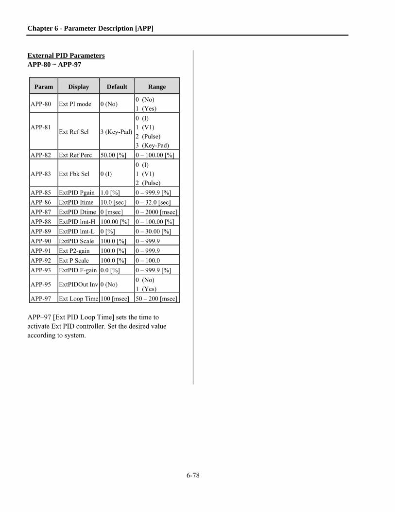
Chapter 6 - Parameter Description [APP]
6-78
External PID Parameters APP-80 ~ APP-97
Param Display Default Range
APP-80 Ext PI mode 0 (No) 0 (No)
1 (Yes)
APP-81
Ext Ref Sel 3 (Key-Pad)
0 (I)
1 (V1)
2 (Pulse)
3 (Key-Pad)
APP-82 Ext Ref Perc 50.00 [%] 0 – 100.00 [%]
APP-83 Ext Fbk Sel 0 (I)
0 (I)
1 (V1)
2 (Pulse)
APP-85 ExtPID Pgain 1.0 [%] 0 – 999.9 [%]
APP-86 ExtPID Itime 10.0 [sec] 0 – 32.0 [sec]
APP-87 ExtPID Dtime 0 [msec] 0 – 2000 [msec]
APP-88 ExtPID lmt-H 100.00 [%] 0 – 100.00 [%]
APP-89 ExtPID lmt-L 0 [%] 0 – 30.00 [%]
APP-90 ExtPID Scale 100.0 [%] 0 – 999.9
APP-91 Ext P2-gain 100.0 [%] 0 – 999.9
APP-92 Ext P Scale 100.0 [%] 0 – 100.0
APP-93 ExtPID F-gain 0.0 [%] 0 – 999.9 [%]
APP-95 ExtPIDOut Inv 0 (No) 0 (No)
1 (Yes)
APP-97 Ext Loop Time 100 [msec] 50 – 200 [msec]
APP–97 [Ext PID Loop Time] sets the time to activate Ext PID controller. Set the desired value according to system.

Chapter 6 - Parameter Description [APP]
6-79
Ext
. P
ID F
/BS
elec
tio
n
Ext
.PID
Par
amet
er
DR
V-2
0
AP
P-
80
Ext
. P
I m
od
e
Ext
.PID
Kf
Lim
it
AP
P-8
8
Ext
. P
IDH
igh
Lim
it F
req
.
pro
c P
I dis
AP
P-9
0
Ga
in
AP
P-8
9
Ext
. P
IDL
ow
Lim
it F
req
.
I/O
-20~
27
Mu
lti-
fun
cti
on
In
pu
tT
erm
inal
Set
tin
g(M
1~M
8)
Ext
. P
ID O
utp
ut
Gai
n
Ext
. P
ID F
Gai
n:
Fee
d F
ow
ard
Ext
. P
ID R
ef
Set
tin
g
Zer
o
AP
P-9
3
AP
P-8
1
I/O
-20~
27
Mu
lti-
fun
cti
on
In
pu
tT
erm
inal
Set
tin
g(M
1~M
8)
AP
P-8
3
Key
pad
3
V1I
Pu
lse
0 1 2
V1I
Pu
lse
Ext
. F
bk
Sel
0 1 2
Ex
t. P
ID R
un
Zer
o
AP
P-8
2
Ext
. R
ef P
erc
Ext
. R
ef S
el
AP
P-0
5
Au
x R
ef S
el
S0,
S1
Mo
de
I/O
-70,
-72
An
alo
g M
eter
Ou
tpu
t S
etti
ng
PID
Au
x. R
ef S
etti
ng
DR
V-0
4
Fre
q M
od
e
Inve
rter
Ref
. F
req
(Mai
n S
pee
d)
Set
tin
g
[ E
xt. P
ID b
lock
dia
gram
]

Chapter 6 - Parameter Description [APP]
6-80
[ Ext. PID internal block diagram]
APP-85
APP-86
APP-87
Ext PID P Gain
Ext PID I Gain
Ext PID D Gain
KP
KI
KD
0
I/O-20~27
Multi-function InputTerminal Setting
(M1~M8)
I Term Clear
KP 2K
APP-91 Ext PID P2 Gain
P Gain2
APP-92 Ext PID P Gain Scale
Ext. PID
Target Freq.Deviation

Chapter 6 – Parameter Description [APP]
6-81
APP-02 , APP-80 (Dual PID operation) ExtPID can be used in the following three cases; 1) controlling another system independently like an external PID controller 2) using both PID controller in APP-02 and External PID controller 3) using ExtPID output as a drive target frequency.
Case 1: Dual PID block diagram
Ext.PID Parameter
DRV-20
APP-80
Ext. PI mode
Ext.PID
Kf
Limit
APP-88
Ext. PID High LimitFreq.
proc PI dis
APP-90
Gain
APP-89
Ext. PID Low LImitFreq.
I/O-20~27
Multi-function InputTerminal Setting
(M1~M8)
Ext. PID OutputGain
Ext. PID F Gain:Feed Foward
Ext. PID Ref Setting
Zero
APP-93
APP-81
I/O-20~27
Multi-function InputTerminal Setting(M1~M8)
APP-83Ext. PID Run
Zero
APP-82
Ext. Ref Perc
S0, S1 Mode
I/O-70,-72
Analog Meter OutputSetting
Ext. Fbk Sel
V11
Keypad3
Ext. Ref Sel
For Connection toExternal Controller
(Other System)
This illustrates controlling another system independently. Set I/O-70 or 72 [S0/S1 mode] to “Ext PID Out” and connect external system to S0 or S1 terminal. When Ext.PID Run signal is ON at the defined terminal in I/O-20~27, it starts its output.

Chapter 6 - Parameter Description [APP]
6-82
Case 2: Dual PID block diagram
Ext.PID Parameter
DRV-20
APP-80
Ext. PI mode
Ext.PID
Kf
Li mi t
APP-88
Ext. PID High LImit Freq.
proc PI dis
APP-90
Gai n
APP-89
Ext. PID Low LImit Freq.
I/O-20~27
Multi- function Input Terminal Setting
(M1~M8)
Ext. PID Output Gain
Ext. PID F Gain:Feed Foward
Ext. PID Ref Setting
Zero
APP-93
APP-81
I/O-20~27
Multi- function Input Terminal Setting(M1~M8)
APP-83Ext. PID Run
Zero
APP-82
Ext. Ref Perc
S0, S1 Mode
I/O-70,-72
아날로그 메타 출력 설정
Ext. Fbk SelV11
Keypad3
Ext. Ref Sel
PID F/BSelection
Accel/Decel
wTarFreq
DRV-14
Target Freq.
APP-02
proc PI mode
PID
Kf
Limit
APP-10
PID HighLImit Freq.
proc PI dis
APP-12
Gain
APP-11
PID LowLimit Freq.
I/O-20~27
Multi-function InputTerminal Setting
(M1~M8)
PID Output Scale
PID F Gain: Feed Foward
PID Aux Ref Setting
Freq
APP-03
APP-04
Aux Ref Mode
APP-05 APP-06
Ext. PID
Aux Ref Sel
8 I
PID F/B
0
1
1
This illustrates dual use of PID controller (APP-02) and External PID controller. Set APP-81 [Ext. Ref Sel] to Analog Input (V1, I, or Pulse) and connect wiring for analog input. To give the digital reference, set APP-81 [Ext. Ref Sel] to “Keypad” and set proper value in APP-82 [Ext. Ref Perc]. Set the Ext. PID Feedback among V1, I, Pulse in APP-83 and connect wiring for analog input. External PID Ref. and feedback are connected to PID controller. When Ext.PID Run signal is ON to the defined terminal in I/O-20~27, it starts its output. S0/S1 terminal can be used to connect to another system.

Chapter 6 – Parameter Description [APP]
6-83
Case 3: Dual PID block diagram
Ext.PID Parameter
DRV-20
APP-80
Ext. PI mode
Ext.PID
Kf
Limit
APP-88
Ext. PIDHigh LImit Freq.
proc PI dis
APP-90
Gain
APP-89
Ext. PIDLow Limit Freq.
I/O-20~27
Multi-function InputTerminal Setting
(M1~M8)
Ext. PIDOutput Gain
Ext. PID F Gain:Feed Foward
Ext. PID Ref Setting
Zero
APP-93
APP-81
I/O-20~27
Multi-function InputTerminal Setting(M1~M8)
APP-83Ext. PID Run
Zero
APP-82
Ext. Ref Perc
S0, S1 Mode
I/O-70,-72
Analog Meter OutputSetting
Ext. Fbk Sel
V11
Keypad3
Ext. Ref Sel
DRV-04
Freq Mode
Inverter Reference Freq.setting (Main Speed Ref.)
ExtPID output can be used for drive target frequency. To activate this function, set analog input (V1, I, Pulse) as a reference value to other system or set APP-81 [Ext. Ref Sel] to “Keypad” and set proper value in APP-82 [Ext. Ref Perc]. Set APP-83 [Ext. Fbk Sel] to Analog input (I, V1, Pulse) and connect wiring for analog input. Set DRV-04 [Freq Mode] to “Ext. PID”, then ExtPID output functions as Drive main speed reference (target frequency). When Ext.PID Run signal is ON in the defined terminal in I/O-20~27, it starts its output and drive performs Accel/Decel with output frequency. Another system can be connected via S0/S1 terminal.


7-1
Chapter7. TroubleShooting&Maintenance
7.1 FaultDisplay When a fault occurs, the drive turns off its output and displays the fault status in parameter DRV-13. When the fault is reset, it gets stored in the fault history. The last five (5) faults are saved in the fault history (parameters AFN-01 through AFN-05) along with the drive’s speed, status, amps, DC Bus voltage and temperature at the time of the fault. AFN-01 is the most recent fault.
LCD Keypad Display
Protective Function
Description
Over Current 1 Over Current
Protection The drive turns off its output when the output current of the drive is more than 200% of the drive standard duty rated current.
Ground Fault Ground Fault
Protection
The drive turns off its output when a ground fault occurs and the ground fault current is more than a preset value. The over current trip function may also protect the drive when a ground fault occurs due to a low ground resistance.
Over Voltage Over voltage
protection
The drive turns off its output if the DC bus voltage increases higher than the OV Trip level. This occurs when the motor decelerates too quickly or when regenerative energy flows back to the drive due to a regenerative load. This fault can also occur due to a surge generated at the input power supply system. OV Trip Level 230Vac drive ~ 390VDC OV Trip Level 460Vac drive ~ 780VDC OV Trip Level 575Vac drive ~ 980VDC NOTE: OV fault may be displayed when an output short occurs. See Over Current-2 fault.
Over Load Inverter/Motor
Overload Protection
When activated with FUN-66, the drive turns off its output when the output current is greater than 120% (FUN-67 default) for 60 secs. (FUN-68 default). NOTE: See Overload retention at bottom of table.
Over Heat Inverter
Over Heat
The drive turns off its output if the internal thermistor detects an over heat condition due to a damaged cooling fan, a foreign substance blocking the heat sink or cooling fan(s), or operation in a high ambient temperature.
E-Thermal Electronic Thermal
The internal electronic thermal overload protection of the drive has determined that the motor has over heated. Overload capacity: 130% of DRV-05 for 1 min (DRV-05 ~ DRV-09) NOTE: See Overload Retention at bottom of table.
Ext. Trip External Trip
Multi-function input configured as “Ext_Trip” has indicated a fault condition. This function is used to turn off the output using an external trip signal. The external trip input can be from an external overload relay, brake resistor temperature switch or other monitoring/safety equipment connected to the drive system.
Low Voltage Low Voltage
Protection
The drive turns off its output if the DC bus voltage decreases below the Low Voltage trip level. LV Trip Level 230Vac drive ~ 200VDC LV Trip Level 460Vac drive ~ 400VDC LV Trip Level 575Vac drive ~ 500VDC NOTE: Insufficient torque and/or over heating of the motor can occur when the output voltage of the drive drops.
Over Current 2 IGBT Short The drive turns off the output if an output short occurs (motor or cables) or if an IGBT is shorted.

Chapter 7 – Trouble Shooting & Maintenance
7-2
LCD Keypad Display
Protective Function
Description
Output Phase Open Output Phase
Open
The drive turns off its output when the one or more of the output phases (U, V, W) is detected open. Open is defined as less than half of AFN-44, No Load Current. Also, if FUN-57 and FUN-58 are set, open is determined as less than FUN-58 level for 1 second.
Input Phase Open Input Phase
Open The drive turns off its output when the one or more of the input phases (R, S, T) is detected open.
BX BX Protection (Drive Disable)
Used as a drive disable function. The drive instantly turns off the output when the BX terminal is activated (ON).
HW-Diag Inverter H/W
Fault
This fault (HardWare fault) is indicated when there is a component failure internal to the drive. Examples: control circuitry (Wdog error, EEP error), NTC open, Fan Lock, Blown fuse. Also, occurs when no motor is connected. See “No Motor Trip” fault.
COM Error CPU Error
Communication Error
This fault is displayed when the drive cannot communicate with the keypad.
Inv. OLT Inverter
Overload
The drive turns off its output when the output current is more than the rating of the drive. Standard Duty: 110% for 1 minute, 130% for 4 seconds. Heavy Duty: 150% for 1 minute, 162.5% for 4 seconds. NOTE: See Overload Retention at bottom of table.
NTC open NTC Open This fault is displayed when the drive internal thermistor is opened (faulty or disconnected).
Ext. OHT External Over
Heat Trip This fault is displayed when the programmed trip temperature from an externally connected thermistor (PTC or NTC) is exceeded.
Fan Lock (150 HP and above)
Fan Loss The drive has detected a loss of cooling fan(s).
Fuse Open (40 HP and above)
High Current (Blown Fuse)
Internal fuse detector has activated indicating a blown DC Bus fuse.
No Motor Trip Low Current Drive has detected low current or no current flow out of drive.
LOV LOI LOA LOR
Lost Cmd
Frequency Reference is
Lost
Based on I/O-18 setting, there are four modes of operation after a Loss of Frequency Reference: continuous operation, free run, decelerate to a stop and fault. LOV: Displayed when ‘V1’ analog frequency reference is lost. LOI: Displayed when ‘I‘ analog frequency reference is lost. LOA: Displayed when pulsed frequency reference is lost. Lost Cmd: Displayed when any analog signal is lost and I/O-18 is set to “protection”. Based on I/O-92 setting, there are three modes of operation after a Loss of Communications: continuous operation, free run and decelerate to stop. LOR: Displayed when communications frequency reference is lost.
Over Lap (Flashing) Programming
Error Displayed when more than one digital input terminal (M1 – M8) is programmed to the same function.
Keypad FLT Loss of Keypad Keypad disconnected when DRV-26 set to Fault.
To reset fault, Press RESET key, close RST-CM terminals or cycle the input power. Overload Retention: The following faults cannot be reset immediately. Overload, E-thermal and Inverter Overload. A cool down period of approximately one minute is required before the drive can be reset.

Chapter 7 – Trouble Shooting & Maintenance
7-3
7.2 FaultRemedy
Protective Function
Cause Remedy
Over Current Protection 1
1) Acceleration/Deceleration time is too short compared to the inertial of the load. 2) Load is larger than the drive rating. 3) Drive turned output on when the motor is still rotating. 4) Output short or ground fault has occurred. 5) Mechanical brake on the motor is engaging too fast before the drive has actually turned off. 6) Components of the main circuit have overheated due to a faulty cooling fan or blocked cooling. 7) Power factor capacitors or other filters are connected to output of drive.
1) Increase Accel or Decel time. 2) Increase drive capacity. 3) Operate only after motor has
completely stopped or use speed search function.
4) Check output wiring for shorts and ground faults.
5) Check mechanical brake operation. 6) Check cooling fan. 7) Remove capacitors or filters from
output of drive. Caution: Operating the drive prior to correcting the original cause of this fault may result in damage to the power section’s IGBTs.
Ground Fault Current Protection
1) A Ground fault has occurred in the output wiring of the drive. 2) A Ground fault has occurred in the motor.
1) Check the output wiring of drive for shorts.
2) Test and/or exchange motor.
Over Voltage Protection
1) Deceleration time is too short compared to the inertia of the load 2) Regenerative load 3) Line voltage too high 4) Output Short Circuit
1) Increase deceleration time. 2) Use dynamic braking /regenerative
resistor option if load is regenerative.
3) Check line voltage. Verify drive input voltage rating is correct. Reduce input voltage if necessary.
4) If OV Fault occurs immediately on start command, check output for short circuit.
Overload
1) Current ouput is larger than the overload settings. 2) Load is larger than drive rating. 3) Incorrect drive capacity selected. 4) Incorrect V/F pattern or control mode set.
1) Verify settings in FUN-66, 67 and 68.
2) Increase capacity of motor and/or drive.
3) Select correct drive capacity. 4) Select correct V/F pattern or control
mode.
Overheat
1) Cooling fan damaged or a foreign substance is blocking fan(s).2) Foreign substance blocking heatsink. 3) Ambient temperature high. 4) Switching Frequency is too high for given loading and ambient
condition.
1) Exchange cooling fans and/or eliminate foreign substance.
2) Check for foreign substances blocking heat sink.
3) Keep ambient temperature under 40 C.
4) Reduce PWM carrier frequency.

Chapter 7 – Trouble Shooting & Maintenance
7-4
Protective Function
Cause Remedy
Electronic Thermal (ETH)
1) Motor has overheated. 2) ETH settings too low. 3) Motor operated at low speeds for extended time. 4) Incorrect drive capacity selected. 5) Incorrect V/F pattern. 6) Load is larger than drive rating.
1) Reduce load and/or running duty. 2) Verify motor and drive capability
and adjust ETH level to a more appropriate level.
3) Install a motor cooling fan with a separate power supply and change ETH settings to forced air cooled motor.
4) Select correct drive capacity. 5) Select correct V/F pattern or
operating mode. 6) Increase drive capacity.
External Trip External Trip has occurred.
1) Eliminate trip condition of external circuit connected to external trip terminal.
2) Disable external trip input.
Low Voltage Protection
1) Line voltage low. 2) Large loads are connected to same line as drive. (welding machine, motors with high starting current connected to the supply line) 3) Faulty inline contactor or one open phase at the input side of the drive
1) Check line voltage. Verify drive rating is correct for input voltage.
2) Increase line capacity if necessary to prevent low line condition.
3) Check for open circuit in wiring, open fuse, or bad contactor on input to drive.
Over Current 2
1) Short has occurred at the output of the drive. 2) Acceleration/Deceleration time is too short compared to the inertial of load. 3) Short has occurred between the upper and lower IGBT.
1) Check motor and output wiring of drive for short circuits.
2) Increase Accel/Decel times. 3) Check (ohm) the output IGBT’s.
Output Phase Open
1) Faulty contactor on output 2) Faulty output wiring 3) Incorrect parameter settings (AFN-40, AFN-44).
1) Check contactor at output of drive. 2) Check output wiring and
connections. 3) Verify parameter settings.
Input Phase Open 1) Faulty input contact (breaker, switch, contactor) 2) Loss of one or more input phases 3) Faulty Input wiring
1) Check continuity of input device 2) Check phase voltages 3) Check input wiring and connections
Bx Fault
Multi-function input configured as “Bx” has detected an inverter disable input. This function is used to disable the drive (turn off the output instantly). The Bx input is typically used for a mechanical brake input or an E-Stop.
Check external control circuitry.
H/W Fault
Wdog error (CPU fault) EEP error (memory fault) ADC Offset (current feedback circuit fault) No Motor Connection or Under Current Level setting
Drive internal failure. Contact Benshaw Customer Service for more information.
Communication Fault
1) Faulty connection between drive and keypad 2) Drive CPU card malfunction
1) Check connector and wiring. 2) Replace drive CPU card.
Inverter Overload 1) Load is larger than drive rating. 2) Incorrect drive capacity selected.
1) Increase motor and/or drive capacity.
2) Select correct drive capacity.

Chapter 7 – Trouble Shooting & Maintenance
7-5
Protective Function
Cause Remedy
NTC Open Internal thermistor has failed open or is disconnected.
125 HP and below, thermistor is internal to IGBT block. Repair is required. 150 HP and above, thermistor is heat sink mounted. Connection is at Main SMPS bd., connector CN7.
Ext. OHT External Thermistor has reached trip temperature. Verify motor heating. Check programming of I/O-97 and I/O-98.
Fan Lock (150 HP and above)
1) Possible fan board failure. 2) Each Fan Bd. Monitors the connected fans internal thermal switch to detect a fan failure.
1) Verify power LED is on for each fan bd. 2) Pins 1 & 2 of connectors CN3 and CN4 on the Fan bd.
Fuse Open (40 HP and above)
1) Internal fuse detector has detected a blown DC Bus Fuse. On 500 HP ~ 700 HP, these are line (input) fuses.
1) Check Fuses. 2) Determine cause of high current.
No Motor Trip
1) The drive has detected no current flow out of the drive. 2) The drive has detected a low current level condition.
1) No motor connection 2) Low level of current set by parameters FUN-57, 58 and 59. Disabled with parameter FUN-57 set to “No”.
Frequency (Speed) Reference is Lost
Loss of Frequency Reference from: LOV - V1 input LOI - I input LOA - Pulsed input LOR - Remote Communications
Eliminate cause of fault.
Over Lap (flashing)
Displayed when more than one digital input terminal (M1 – M8) is programmed to the same function.
Check parameters I/O-20 ~ I/O-27 for duplication.

Chapter 7 – Trouble Shooting & Maintenance
7-6
7.3 Troubleshooting
Condition Item to Check
The Motor Does
Not Rotate.
1) Main circuit inspection:
- Is the input (line) voltage normal? (Is the LED in the drive lit?)
- Is the motor connected correctly?
2) Input signal inspection:
- Check the operating signal input to the drive.
- Check the forward and the reverse signal input to the drive?
- Check the command frequency signal input to the drive.
3) Parameter setting inspection:
- Is the reverse prevention (FUN-01) function set?
- Is the Drive mode (DRV-03) set correctly?
- Is the command frequency set to 0Hz?
4) Load inspection:
- Is the load too large or is the motor jammed? (Mechanical brake)
5) Other:
- Is an alarm or fault displayed on the keypad or is the alarm LED lit? (STOP LED blinks)
The Motor
Rotates in
Opposite
Directions.
- Is the phase sequence of the output terminals U, V, W correct?
- Is the starting signal (forward/reverse) connected correctly?
The Difference
Between the
Rotating Speed
and the Reference
is too Large.
- Is the frequency reference signal correct? (Check the level of the input signal)
- Are the following parameter settings correct?
Lower Limit Frequency (FUN-34), Upper Limit Frequency (FUN-35),
Analog Frequency Gain (I/O-1~10)
- Is the input signal line influenced by external noise or ground loops? (Use a shielded wire)
The Drive Does
Not Accelerate or
Decelerate
Smoothly.
- Is the acceleration/deceleration time is set too short a period of time?
- Is the load too large?
- Is the Torque Boost (AFN-68, 69) value is too high that the current limit function and the stall
prevention function do not operate properly?
The Motor
Current is Too
High.
- Is the load too large?
- Is the Torque Boost Value (manual) too high?
- Is the motor rated voltage parameter set correctly?
- Is the input voltage low?
The Rotating
Speed Does Not
Increase.
- Is the Upper Limit Frequency (FUN-35) value correct?
- Is the load too large?
- Is the Torque Boost (FUN-68, 69) value too high that the stall prevention function (FUN-70, 71)
does not operate correctly?
The Rotating
Speed Oscillates
When the Drive is
Operating.
1) Load inspection:
- Is the load really oscillating?
2) Input signal inspection:
- Is the frequency reference signal oscillating or being disturbed by noise?
3) Other:
- Is the wiring too long when the drive is utilizing V/F control? (over 500m)

Chapter 7 – Trouble Shooting & Maintenance
7-7
7.4 HowtoCheckPowerComponents
Turn the power off and wait until the Main DC Bus Electrolytic Capacitors are discharged to a safe level.
The voltage between terminal P1-N (or P2-N) should be less than 30VDC.
Disconnect input (R,S,T) and output (U,V,W) wiring. Proper test results may not be achieved if any of the input or output wiring remains connected.
A large reading of resistance such as Mega ohms (or OL) will be displayed when the circuit is Open. When the circuit is closed, the resistance values will range from a few ohms to tens of ohms. Sometimes, a circuit will seem to be closed (or give negative resistance readings) due to the meter charging up the electrolytic capacitors within the circuit but high resistance will be eventually be displayed when the capacitors are charged. A zero ohm reading (or short) indicates a bad (shorted) component.
The measured values may not always be the exact same values depending on modules and tester types however they should be similar.
WARNING

Chapter 7 – Trouble Shooting & Maintenance
7-8
1) Diode module and IGBT module check (7.5~ 40HP)
Module Test polarity Check
value Number
Test polarity Check value + - + -
Diode
D1 R DCP+ Closed
D4 R N Open
DCP+ R Open N R Closed
D2 S DCP+ Closed
D5 S N Open
DCP+ S Open N S Closed
Diode D3 T DCP+ Closed
D6 T N Open
DCP+ T Open N T Closed
IGBT
Tr1 U DCP Closed
Tr4 U N Open
DCP U Open N U Closed
Tr3 V DCP Closed
Tr6 V N Open
DCP V Open N V Closed
Tr5 W DCP Closed
Tr2 W N Open
DCP W Open N W Closed
Charge resistor
M/C
R
S
T
U
V
W
D1
+Electrolytic capacitors
DCP
N
Tr3
Tr6
Tr5
Tr2
Tr1
Tr4
DCP+
D2 D3
D4 D5 D6

Chapter 7 – Trouble Shooting & Maintenance
7-9
2) Power Component Check – 50 HP ~ 125 HP
Module
Test polarity
Reading Module
Test polarity
Reading+ - + - DC Bus Fuse Fuse 1 across fuse Closed
Fuse Indicator Fuse 1
across indicator Closed
SCR's *SCR1
D1 R P2 (+) Open Diodes
D4 R N (-) Open
P2 (+) R Open N (-) R Closed
SCR2 S P2 (+) Open
D5 S N (-) Open
P2 (+) S Open N (-) S Closed
SCR3 T P2 (+) Open
D6 T N (-) Open
P2 (+) T Open N (-) T Closed
* measurement is across Rpre/D1 (series) in parallel with SCR1
A 125 HP has 6 SCR/Diode modules (SCR1a, SCR2a, D1a, D2a, etc.)
IGBT's Tr1
U P2 (+) Closed IGBT's Tr4
U N (-) Open
P2 (+) U Open N (-) U Closed
Tr3 V P2 (+) Closed
Tr6 V N (-) Open
P2 (+) V Open N (-) V Closed
Tr5 W P2 (+) Closed
Tr2 W N (-) Open
P2 (+) W Open N (-) W Closed

Chapter 7 – Trouble Shooting & Maintenance
7-10
3) Power Component Check – 150 HP ~ 250 HP
Module
Test polarity
Reading Module
Test polarity
Reading+ - + -
DC Bus Fuses
Fuse 1 across fuse Closed Fuse Indicators
Fuse 1 across indicator Closed
Fuse 2 across fuse Closed Fuse 2 across indicator Closed
Fuses are in parallel, visual check indicators first
SCR's SCR1
R P2 (+) Open Diodes D4
R N (-) Open
P2 (+) R Open N (-) R Closed
SCR2 S P2 (+) Open
D5 S N (-) Open
P2 (+) S Open N (-) S Closed
SCR3 T P2 (+) Open
D6 T N (-) Open
P2 (+) T Open N (-) T Closed
All SCR's have a snubber circuit across them.
IGBT's Tr1(1a)
U P2 (+) Closed IGBT's Tr4(4A)
U N (-) Open
P2 (+) U Open N (-) U Closed
Tr3(3a) V P2 (+) Closed
Tr6(6A)V N (-) Open
P2 (+) V Open N (-) V Closed
Tr5(5a) W P2 (+) Closed
Tr2(2A)W N (-) Open
P2 (+) W Open N (-) W Closed

Chapter 7 – Trouble Shooting & Maintenance
7-11
4) Power Component Check – 350 HP ~ 400 HP
Module
Test polarity
Reading Module
Test polarity
Reading+ - + -
DC Bus Fuses
Fuse 1 across fuse Closed Fuse Indicators
Fuse 1 across indicator Closed
Fuse 2 across fuse Closed Fuse 2 across indicator Closed
Fuse 3 across fuse Closed Fuse 3 across indicator Closed
Fuses are in parallel, visual check indicators first
SCR's SCR1
R P2 (+) Open Diodes D4
R N (-) Open
P2 (+) R Open N (-) R Closed
SCR2 S P2 (+) Open
D5 S N (-) Open
P2 (+) S Open N (-) S Closed
SCR3 T P2 (+) Open
D6 T N (-) Open
P2 (+) T Open N (-) T Closed
SCR3: Measurement is D1/D2 and Pre-Charge Resistor
IGBT's Tr1
U P2 (+) Closed IGBT's Tr4
U N (-) Open
P2 (+) U Open N (-) U Closed
Tr3 V P2 (+) Closed
Tr6 V N (-) Open
P2 (+) V Open N (-) V Closed
Tr5 W P2 (+) Closed
Tr2 W N (-) Open
P2 (+) W Open N (-) W Closed

Chapter 7 – Trouble Shooting & Maintenance
7-12
5) Power Component Check – 500 HP ~ 700 HP
Module
Test polarity
Reading Module
Test polarity
Reading+ - + - Line Fuses
Fuse 1 R across fuse Closed Fuse Indicators
Fuse 1 across indicator Closed
Fuse 2 S across fuse Closed Fuse 2 across indicator Closed
Fuse 3 T across fuse Closed Fuse 3 across indicator Closed These indicators are connected in series.
SCR's SCR1/ SCR2
R P1 (+) Open Diodes D1/ D2
R N (-) Open
P1 (+) R Open N (-) R Closed
SCR3/ SCR4
S P1(+) Open D3/ D4
S N (-) Open
P1(+) S Open N (-) S Closed
SCR5/ SCR6
T P1(+) Open D5/ D6
T N (-) Open
P1(+) T Open N (-) T Closed
SCR5/6: Measurement is D7 and Pre-Charge Resistor IGBT's
Tr1(1a) U P1(+) Closed IGBT's
Tr4(4a)U N (-) Open
P1(+) U Open N (-) U Closed
Tr3(3a) V P1(+) Closed
Tr6(6a)V N (-) Open
P1(+) V Open N (-) V Closed
Tr5(5a) W P1(+) Closed
Tr2(2a)W N (-) Open
P1(+) W Open N (-) W Closed
Chapter 7 – Trouble Shooting & Maintenance
7-13
7.5 Maintenance The Benshaw series of drive’s (Models SG, S4 and GX) are an industrial electronic product with advanced semiconductor components. A reasonable life expectancy of 8 to 10 years can be expected. However, there are factors that may affect their continued long term operation. Environmental issues (temperature and humidity) and mechanical issues (vibration and connections) are the most common reasons for premature failure of drives. To avoid problems, it is recommended to perform routine inspections of the drive.
7.5.1 Precautions
1) Be sure to remove the drive’s power input while performing maintenance. Lock out all sources of power.
2) Preventive maintenance should always be performed by a trained technician. 3) Be sure to perform maintenance only after checking that the DC bus voltage has discharged. The
voltage between terminal P1-N (or P2-N) should be less than 30VDC. The DC bus capacitors in the electronic circuit can still be charged even after the power is turned off. The DC bus LED is not a definitive indication of the absence of DC voltage.
7.5.2 PeriodicInspectionSummary Refer to the attached Table for specific frequency of inspection
1) The conditions of the installed location a) Observe any physical damage to enclosure or enclosure degradation. b) Any signs of liquid leakage into the enclosure. c) Any signs of corrosion or rust resulting from leakage into the enclosure.
2) The conditions of the drive cooling. Causes for abnormal heating are:
a) Check for any deposits or dirt inside the enclosure, in the cooling fans/filters and the drive fan(s). Remove with compressed air.
b) Check the rotating condition of the cooling fan(s)
3) Abnormal vibration a) Are there any loose nuts or bolts as a result of the vibration? b) Loose connections will show signs of heated connectors and wires. Tighten or replace.

Chapter 7 – Trouble Shooting & Maintenance
7-14
7.5.3 PeriodicInspection
Inspection Item Inspection
Period
Inspection Method Criterion
Customer use
Check/ Initial /Date
Mon
thly
1 ye
ar
2 ye
ar
En
viro
nm
ent
Ambient Temperature/Humidity
Is the ambient temperature and humidity
adequate? X
Measure/Monitor (Thermometer, Hygrometer,
Recorder)
Temperature: -10~+40C
Humidity: Under 90%
non-condensing
Ph
ysic
al I
nsp
ecti
on
Physical
Any signs of physical damage to the enclosure
of the drive?
X
Visual Yes/No
Any signs of liquid leaking into enclosure of
the drive?
X
Are there any signs of rust inside the drive
enclosure?
X
Are there any signs of rust inside the panel where the drive is
housed.?
X
Are there any abnormal vibrations or oscillations
of the drive/Panel?
X
Physical (Cables and Connections)
Are there any signs of overheated connections
(discolored lugs, insulation melted)?
X
Visual Yes/No
Are there any signs of rusted or corroded
connections?
X
Are there any signs of cracked terminal blocks?
X
Is there any damage to cable insulation?
X
Physical (Fans)
Inspect fans and filters for dust
accumulation/debris. X
Inspect fans for free rotation.
X
Non
-Pow
ered
Dri
ve
Ch
eck
s/M
easu
rem
ents
IGBT Module Check the resistance between each of the
terminals.
X
Disconnect the drive three phase input and measure the resistance between R, S, T
and P, N.
Refer to "How to Check
Power Components”
using Digital or Analog meter.
Input Diode/SCR Modules
Disconnect the drive three phase output and measure the resistance between U, V, W
and P, N.
DC Bus Capacitors
Is there any liquid coming out?
X
Visual check Yes/No
Is the safety pin (pressure relief) out, or is there any
swelling?
X

Chapter 7 – Trouble Shooting & Maintenance
7-15
Inspection Item
Inspection
Period
Inspection Method Criterion Customer useCheck/ Initial
/Date
Mon
thly
1 ye
ar
2 ye
ar
Pow
ered
dri
ve -
Not
Ru
nn
ing
Ope
rati
ng C
heck
s/M
easu
rem
ents
Input Voltages
Is the input voltage from the main within spec of
the drive?
X
Measure the voltage between the terminals R, S, T.
drive rating +/-15%
Is the input voltage from the main balanced within
spec of the drive?
X 2%
DC Bus Voltage
Is the DC Bus Higher or Lower than normal?
X Measure the DC Voltage between the Pos. and Neg. terminals of the
drive.
Input Voltage x SQRT2 (+/-
10%)
Cooling Fan Is there any abnormal oscillations or noise?
X
Turn OFF the power and turn the fan by hand.
Must rotate smoothly.
Trip Circuit (Input to
drive)
Is drive trip circuit functional?
X
Identify the drive input trip circuit. Open or Close external trip
mechanism. drive must trip.
Pow
ered
Dri
ve -
Ru
nn
ing
Op
erat
ing
Ch
eck
s/M
easu
rem
ents
Output Voltages
Is there any voltage imbalance between
phases of the output?
X Measure the voltage between the
output terminals U, V and W.
for 230V (4V) for 460V (8V) for 600V (12)
Does the displayed Output Voltage agree with measurement?
X
Display parameter for Output Voltage, compare to measured
value.
Tol. -10%+20% Note 1
Output Current
Is there any current imbalance between
phases of the output?
X Measure the current out of each
phase U, V, W. Tol. +/-3%
Note 1
Does the displayed Output Current agree with
measurement?
X Display parameter for Output Current, compare to measured
value.
Tol. +/-5% Note 1
General
Are there any abnormal vibrations or noise?
X
Auditory, sensory, visual check. Yes/No
Is there any unusual odor? X Check for overheat and damage. Yes/No
Note 1
Multimeter measurements of drive output could vary depending on the type of meter.
7.5.4 PartsReplacement
Part name Period Comments
Cooling fans 2-3 years Exchange for a new fan after consulting Benshaw customer service center.
Electrolytic capacitors
5 years Perform periodic inspections every year. Exchange after testing and consulting Benshaw customer service center. The Recommended capacitance level to replace a capacitor in the main/control circuit is when it has 85% or less of its initial value of capacitance.
Relays / Contactor - Exchange for a new part after consulting Benshaw customer service center.

Notes :
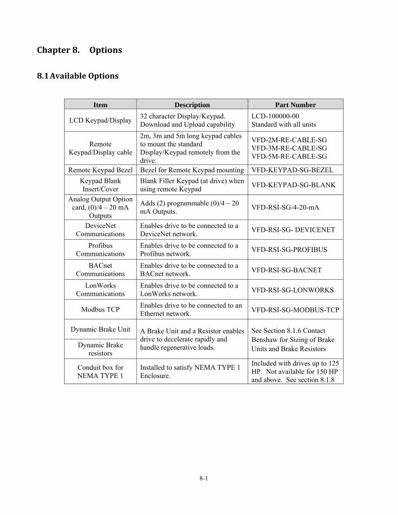
8-1
Chapter8. Options
8.1 AvailableOptions
Item Description Part Number
LCD Keypad/Display 32 character Display/Keypad. Download and Upload capability
LCD-100000-00 Standard with all units
Remote Keypad/Display cable
2m, 3m and 5m long keypad cables to mount the standard Display/Keypad remotely from the drive.
VFD-2M-RE-CABLE-SG VFD-3M-RE-CABLE-SG VFD-5M-RE-CABLE-SG
Remote Keypad Bezel Bezel for Remote Keypad mounting VFD-KEYPAD-SG-BEZEL
Keypad Blank Insert/Cover
Blank Filler Keypad (at drive) when using remote Keypad
VFD-KEYPAD-SG-BLANK
Analog Output Option card, (0)/4 – 20 mA
Outputs
Adds (2) programmable (0)/4 – 20 mA Outputs.
VFD-RSI-SG-4-20-mA
DeviceNet Communications
Enables drive to be connected to a DeviceNet network.
VFD-RSI-SG- DEVICENET
Profibus Communications
Enables drive to be connected to a Profibus network.
VFD-RSI-SG-PROFIBUS
BACnet Communications
Enables drive to be connected to a BACnet network. VFD-RSI-SG-BACNET
LonWorks Communications
Enables drive to be connected to a LonWorks network. VFD-RSI-SG-LONWORKS
Modbus TCP Enables drive to be connected to an Ethernet network. VFD-RSI-SG-MODBUS-TCP
Dynamic Brake Unit A Brake Unit and a Resistor enables drive to decelerate rapidly and handle regenerative loads.
See Section 8.1.6 Contact Benshaw for Sizing of Brake Units and Brake Resistors Dynamic Brake
resistors
Conduit box for NEMA TYPE 1
Installed to satisfy NEMA TYPE 1 Enclosure.
Included with drives up to 125 HP. Not available for 150 HP and above. See section 8.1.8

Chapter 8 – Options
8-2
8.1.1 LCDKeypadFor Replacement or Remote Mounting - Part # LCD-100000-00
LCD Keypad (Weight: 140 g)
8.1.2 RemoteKeypadCable
Part # Description VFD-2M-RE-Cable-SG 2m (6.6ft) Remote cable
VFD-3M-RE-Cable-SG 3m (9.9ft) Remote cable
VFD-5M-RE-Cable-SG 5m (16.5ft) Remote cable
8.1.3 4–20mAOutputOptionCard Part # VFD-RSI-SG-4-20-MA, Manual # 890027-11-xx. This option card adds (2) isolated outputs (0/4 – 20 mA) to the drive. See the EXT Group of parameters.
8.1.4 DeviceNetCommunicationsOptionCard Part # VFD-RSI-SG-DEVICENET, Manual # 890027-05-xx. EDS file required. This option card enables the SG drive to be connected to a DeviceNet network.

Chapter 8 – Options
8-3
8.1.5 ProfibusCommunicationsOptionCard Part # VFD-RSI-SG-PROFIBUS, Manual # 890027-06-xx. GSD file required. This option card enables the SG drive to be connected to a Profibus network.
8.1.6 BACnetCommunicationsOptionCard Part # VFD-RSI-SG-BACNET. This option card enables the SG drive to be conected to a BACnet network.
8.1.7 LonWorksCommunicationsOptionCard Part # VFD-RSI-SG-LONWORKS. This option card enables the SG drive to be connected to a LonWorkst network.
8.1.8 ModbusTCPOptionCard Part # VFD-RSI-SG-MODBUS-TCP. This option card enables the SG drive to be connected to an Ethernet network.
8.1.9 DynamicBrakingUnit In cases where a short stopping time is desired or a high inertia or regenerative load requires dynamic braking capability, an optional Dynamic Braking (DB) unit can be added to the SG drive. Contact Benshaw for more information regarding this option. Dynamic Brake Resistors are NOT included with the DB Unit. 1) Dynamic Braking Unit Models
Input voltage Drive capacities DB Unit Dimensions
230V 1 ~ 20 HP VFD-RSI-DBU-020-2
Refer to 4)
25 ~ 30 HP VFD-RSI-DBU-030-2 40 HP VFD-RSI-DBU-050-2
460V
1 ~ 20 HP VFD-RSI-DBU-020-4 25 ~ 30 HP VFD-RSI-DBU-030-4 40 ~ 50 HP VFD-RSI-DBU-050-4 60 ~ 75 HP VFD-RSI-DBU-075-4 100 HP VFD-RSI-DBU-100-4 > 100 HP Contact Benshaw
The units listed in the table above are 230V and 460V, 10% duty cycle brake units. If application requires heavy duty brake modules and resistors or for use with a 600V VFD, contact Benshaw for sizing and selection.

Chapter 8 – Options
8-4
2) DB Unit Terminal layout
Terminals Description
G Ground terminal B2 Connect to DB Resistor’s B2 B1 Connect to DB Resistor’s B1 N Connect to drive terminal N P Connect to drive terminal P1 CM Over Heat Common
OH* Over Heat Trip output terminal (Open Collector output: 20mA, 27V DC)
3) Wiring for DB unit and DB resistor (for 7.5~40HP drives, 50HP~125HP similar)
B2 B1 N P CM OH G
AC Input
50/60 Hz
U
V W
G
R(L1)S(L2)T(L3)
N(-)
3
MCCB(Option)
M1
M2
M3
M4
M6
M8
M7
MOTOR
Programmable Digital Input : Ext Trip
Common Terminal
Fault Contact Output less than AC250V (DC30V), 1A
P2(+)P1(+)
M5
S1
S0
5G
Output Frequency Meter
Output Voltage Meter
Common for output meter signal
Max. output voltage : 12V Source Max. : 30mA Sink Max. : 20mA
3A
3C
3B
CM
DB Resistor
TH1
TH2
Short
NB1
GB2B2
B1
DB Unit
Max distance between P & P2: 5m
P

Chapter 8 – Options
8-5
4) Dynamic Brake Unit Dimensions
N
ynamic
T P
D
R
S(P2) W
N
P
B2
B1
G
rakingB
WIRING
V
U
IM
nitU
B2
B1

Chapter 8 – Options
8-6
5) DB Unit Monitoring LEDs
8.1.10 DynamicBrakingResistor(s) The RSI-SG drive does not contain a built-in dynamic braking transistor or resistor. Benshaw offers a wide selection of resistor options depending on drive size, enclosure requirements, and desired braking duty cycle. Contact Benshaw for more information regarding the sizing and selection of dynamic braking resistors.
8.1.11 NEMATYPE1ConduitBox The NEMA TYPE 1 Conduit Box enclosure enables an SG drive to be installed on the wall without any additional enclosures and satisfy NEMA Type 1 requirements. The conduit box is included with drives 125 HP and below. Drives 150 HP and above do not have a conduit box. See details on the following pages.
LED DescriptionOHT
(GREEN, LEFT)
When heat sink is overheated the overheat protection is activated and the OHT LED is turned ON.
POWER (RED)
The POWER LED is turned ON upon inverter Power is ON.
RUN (GREEN, RIGHT)
The RUN LED will blink when the DB Unit is operating normally.
OHT POWER RUN

Chapter 8 – Options
8-7
Figure A. Conduit Boxes for 20 HP ~ 40 HP
VFD-RSI-025-SG-4B
VFD-RSI-020-SG-4B
VFD-RSI-025-SG-6B
VFD-RSI-020-SG-6B
PART NUMBER
600
600
VOLTS
PART NUMBER
460
460
VOLTS
25
20
HP
25
HP
20
VFD-RSI-020-SG-2B
VFD-RSI-025-SG-2B
PART NUMBER VOLTS
230
230
HP
25
20
BOTTOM3.68
[93.50]
9.29 [235.99]
3.21 [81.61]
6.00 [152.50]
6.47 [164.21]
5.48 [139.19]
6.46 [164.19]
FRONT(3) 1.968" [50]
DIAMETERKNOCKOUTS
9.29 [235.99]
5.48 [139.19]
SIDE
3.29 [83.49]
(2) 1.97" [50.00]DIAMETERKNOCKOUTS3.15
[79.98]TYP.
7.91 [200.79]
BOTTOM
2.72 [69.19]
3.71 [94.18]
3.09 [78.49]
7.51 [190.78]
3.71 [94.18]
(1) 1.378" [35]DIAMETERKNOCKOUTS
7.91 [200.79]
FRONT
3.21 [81.61]
SIDE
3.31 [84.00]
2.56 [65.02]
TYP.
3.15 [80.01]
CONDUIT BOX FOR
CONDUIT BOX FOR
3.21 [81.61]
VOLTS
230
230
460
460
VOLTS
VOLTS
600
600
PART NUMBER
VFD-RSI-030-SG-6B
VFD-RSI-040-SG-6B
VFD-RSI-040-SG-2B
VFD-RSI-030-SG-2B
PART NUMBER
VFD-RSI-030-SG-4B
VFD-RSI-040-SG-4B
PART NUMBER
30
40
HP
HP
40
30
40
30
HP

Chapter 8 – Options
8-8
Figure B. Conduit Boxes for 50 HP ~ 75 HP
(5) .866" [22]DIAMETERKNOCKOUTS
2.36 [59.99]
7.09 [179.98]
2.27 [57.58]
11.18 [284.00]
11.81 [300.00]
(3) 2.0" [51]DIAMETERKNOCKOUTS
4.59 [116.48]
0.93 [23.60]
11.81 [300.00]
FRONT
5.12 [130.00]
5.98 [151.99]
SIDE
0.63 [15.98]
5.12 [130.00]
BOTTOM
1.77 [45.01]
TYP.
2.36 [60.02]
0.32 [8.00]
VFD-RSI-060-SG-4B
VFD-RSI-075-SG-4B
VFD-RSI-050-SG-4B
PART NUMBER
460
460
60
75
VOLTS
460
HP
50
CONDUIT BOX FOR
6.24 [158.57]4.70
[119.41]
3.54 [89.99]
TYP.
600
VOLTS
600
600
VFD-RSI-075-SG-6B
PART NUMBER
VFD-RSI-050-SG-6B
VFD-RSI-060-SG-6B
75
60
50
HP
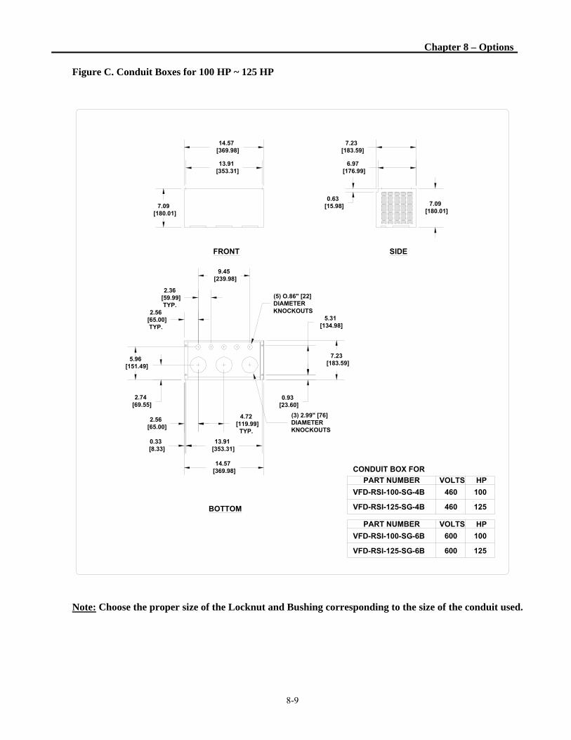
Chapter 8 – Options
8-9
Figure C. Conduit Boxes for 100 HP ~ 125 HP
Note: Choose the proper size of the Locknut and Bushing corresponding to the size of the conduit used.
VFD-RSI-125-SG-6B
PART NUMBER
VFD-RSI-100-SG-6B
600 125
600
VOLTS
100
HP
CONDUIT BOX FOR
13.91 [353.31]
14.57 [369.98]
FRONT
7.23 [183.59]
6.97 [176.99]
SIDE
7.09 [180.01]
BOTTOM
0.63 [15.98]7.09
[180.01]
2.74 [69.55]
5.96 [151.49]
(3) 2.99" [76]DIAMETERKNOCKOUTS
(5) O.86" [22]DIAMETERKNOCKOUTS
14.57 [369.98]
7.23 [183.59]
2.36 [59.99]
TYP.
9.45 [239.98]
5.31 [134.98]
0.93 [23.60]
2.56 [65.00]
4.72 [119.99]
TYP.
2.56 [65.00]
TYP.
0.33 [8.33]
13.91 [353.31]
VFD-RSI-125-SG-4B
VFD-RSI-100-SG-4B
PART NUMBER
460 125
VOLTS
460 100
HP

Notes :

9-1
Chapter9. RS485/MODBUS‐RTUCommunication
9.1 Introduction The SG drive can be controlled and monitored by the sequence program of the PLC or other master module. Drives or other slave devices may be connected in a multi-drop fashion on the Modbus-RTU network and may be monitored or controlled by a single PLC or PC. Parameter settings and changes are available through a PC.
9.1.1 FeaturesDrive can be easily applied for Factory automation because operation and monitoring is available by User-program.
* Parameter change and monitoring is available via computer. (Ex: Accel/Decel time, Freq. Command, etc.)
* Interface type of Modbus reference: 1) Allows the drive to communicate with any other computers. 2) Allows connection of up to 31 drives with multi-drop link system. 3) Noise-resistant interface.
9.1.2 ConnectionGuideforModbus‐RTUCommunicationwithPC,PLCandRS232/485
* REPEATER is not a required item but helps communication in long-distance communication or high noise environment.
9.1.3 BeforeInstallation Before installation and operation, this should be read thoroughly. If not, it can cause personal injury or damage to other equipment.
PC
Drive #1
Drive #2
Drive #n
Converter
RS232C/485 or
USB-485
Repeater

Chapter 9 – RS485/Modbus RTU Communications
9-2
9.2 Specification
9.2.1 PerformanceSpecification
Item Specification
Transmission form Bus method, Multi-drop Link System Applicable inverter SG series Connectable drives Max 31 Transmission distance Max. 1,200m (Within 700m Recommended) Recommended wire 0.75mm2(12AWG), Shield Type Twisted-Pair Wire
9.2.2 HardwareSpecification
Item Specification
Installation Use C+, C-,CM terminals on control terminal block Power supply Use Insulated power from the inverter power supply
9.2.3 CommunicationSpecificationItem Specification
Communication speed 19,200/9,600/4,800/2,400/1,200 bps selectable Communication system Half duplex system Character system ASCII (8 bit) Stop bit length 1 bit Check Sum (CRC16) 2 byte Parity bit None
Protocol supported Parameter Read/Write, Monitoring parameter register/execution Broadcasting
9.2.4 Installation Connecting the communication line 1) Connect the Modbus-RTU communication line to the inverter’s (C+), (C-) and CM terminals of the control terminals. 2) Connect the CM terminal among inverters for stable communication. 3) Check the connection and turn ON the inverter. 4) If the communication line is connected correctly set the communication-related parameters per the following table: 5) Install a repeater to upgrade the communication speed or longer than 1200mm communication line is used. Repeater is required for upgrading communication quality in the noise-high environment.

Chapter 9 – RS485/Modbus RTU Communications
9-3
9.2.5 CommunicationParametersParameter Display Name Set value Unit Default
DRV_03 Drive mode Drive mode Int. 485 Fx/Rx-1
DRV_04 Freq mode Freq mode Int. 485 KeyPad-1
DRV_91 Drive mode2 Drive mode 2 KeyPad Fx/Rx-1 Fx/Rx-2
Fx/Rx-1
DRV_92 Freq mode2 Freq mode 2
KeyPad-1 KeyPad-2 V1 V1S I V1+I Pulse
KeyPad-1
I/O_20~27 M1 ~ M8 Programmable Digital Inputs
Loc/Rem
I/O_90 Inv No Inverter number 1~250 1
I/O_91 Baud rate Communication speed
1200 bps 2400 bps 4800 bps 9600 bps 19200 bps
9600 bps
I/O_92 COM Lost Cmd
Operating mode when communication signal is lost
None FreeRun Stop
None
I/O_93 COM Time Out
Time to determine whether Communication signal is lost.
0.1~120.0 sec 1.0
I/O_94 Delay Time Communication Response Delay Time
2 to 1000 msec msec 5.0
9.3 Operation
9.3.1 OperatingSteps1) Check whether the computer and the inverter are connected correctly. 2) Turn ON the inverter. But, do not connect the load until stable communication between the computer and the
inverter is verified. Start the operating program for the inverter from the computer. 3) Operate the inverter using the operating program for the inverter. 4) Refer to “9.6 Troubleshooting” if the communication is not operating normally. 5) Turn the inverter J3 switch ON to connect the terminating resistor for the end of network.
* Connect to C+,C-,CM terminal on the control terminal. Pay attention to polarity(+, -).
* Maximum number of connected drives is 31.

Chapter 9 – RS485/Modbus RTU Communications
9-4
9.4 CommunicationProtocol(Modbus‐RTU) Use Modbus-RTU protocol (Open protocol). Computer or other hosts can be Master and Slave. The drive responds to Read/Write command from Master. Supported function code Function code Description 0x03 Read Hold Register 0x04 Read Input Register 0x06 Preset Single Register 0x10 Preset Multiple Register Exception code
Function code Description 0x01 ILLEGAL FUNCTION 0x02 ILLEGAL DATA ADDRESS 0x03 ILLEGAL DATA VALUE 0x06 SLAVE DEVICE BUSY
User define 0x14 1. Write Disable (Address 0x0004 value is 0)
2. Read Only or Not Program during Running.

Chapter 9 – RS485/Modbus RTU Communications
9-5
9.5 ParameterCodeList<Common area>: Area accessible regardless of drive model (Note 1)
Address (HEX)
Parameter Name Unit Read/Write
Data Value (Hex)
0x0000 Drive model - R 4: RSi-SG-XXX
0x0001 Drive capacity - R
4: 5.5 5: 7.5 6: 11 7: 15 8: 18.5 9: 22 A: 30 B: 37 C: 45 D: 55 E: 75 F: 90 10: 110 11: 132 12: 160 13: 200 14: 220 15: 280 16: 375 17: 450 (Unit : kW)
0x0002 Drive Input Voltage - R 0: 220V 1: 460V 2: 575V 0x0003 S/W Version - R 0100: Ver. 1.0, 0101: Ver. 1.1, 0004: Ver.0.4 0x0005 Frequency Reference 0.01Hz R/W
0x0006
Run Command (Bits 0 – 2)
-
R/W
BIT 0: Stop (S)
BIT 1: Forward run (F)
BIT 2: Reverse run (R)
BIT 3: Fault reset (0->1)
BIT 4: Emergency Stop
BIT 5: Not used
Start/Stop (Bits 6, 7)
R
BIT 6, BIT 7: Run/Stop command source
0:Terminal 1:Keypad 2:Comm.Opt. 3: Int. 485
Frequency Reference (Bits 8 ~ 14)
Values 0 ~ 29 are decimal values
BIT 8 ~14: Freq. Reference
0 ~ 16: Multi-step speed freq. (0, 2~16)
17 ~ 19: Up/Down (Up, Down, UD Zero)
20 ~ 25: Analog
20:V1 21: V1S 22: I 23:NA 24:V1+I
25:Pulse 26:Int.485 27:Jog 28:Ext.PID
29: Comm.Opt.Bd.
BIT 15: set when Network error
0x0007 Acceleration Time 0.1 sec R/W 0x0008 Deceleration Time 0.1 sec R/W 0x0009 Output Current 0.1 A R 0x000A Output Frequency 0.01 Hz R 0x000B Output Voltage V R 0x000C DC Link Voltage 0.1 V R 0x000D Output Power 0.1 kW R
0x000E Operating Status - R
BIT 0: Stop BIT 1: Forward Run BIT 2: Reverse Run BIT 3: Fault (Trip) BIT 4: Accelerating BIT 5: Decelerating BIT 6: Output Frequency Arrival BIT 7: DC Braking BIT 8: Stopping BIT 9: Not Used BIT 10: BrakeOpen BIT 11: Forward Run Command BIT 12: Reverse Run Command BIT 13: Start/Stop via Int. 485 (or Opt. Bd.) BIT 14: Freq. Ref via Int. 485 (or Opt Bd.)
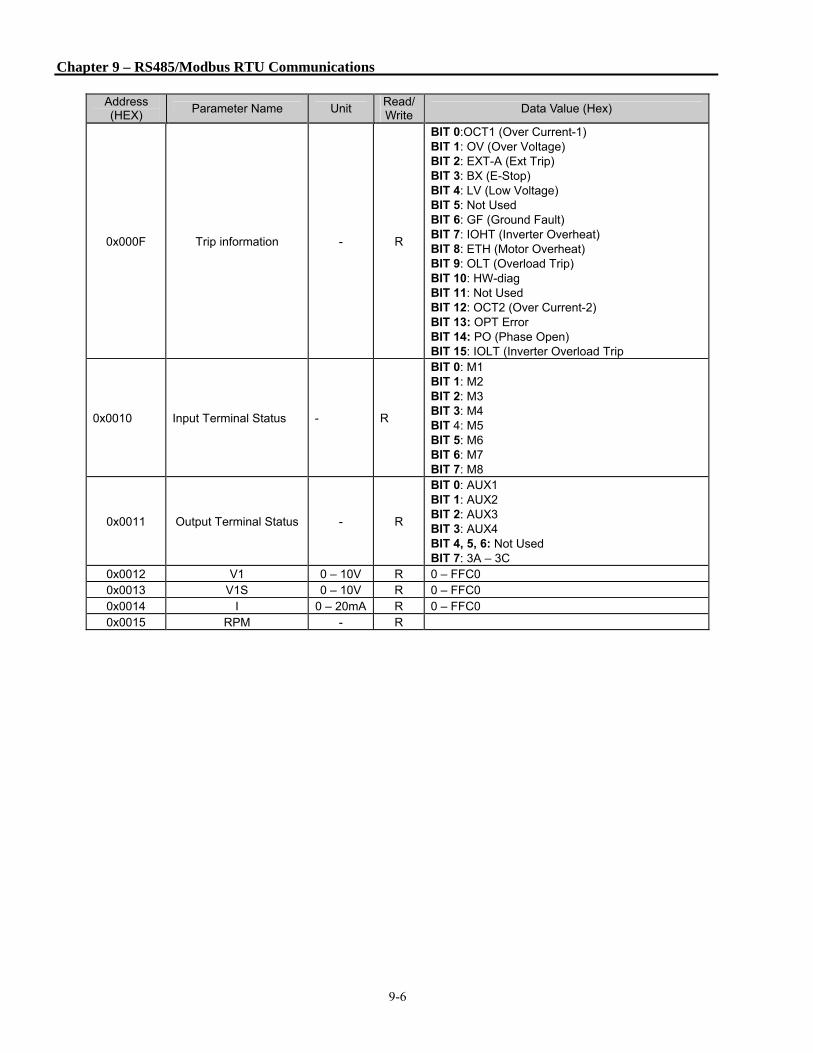
Chapter 9 – RS485/Modbus RTU Communications
9-6
Address (HEX)
Parameter Name Unit Read/Write
Data Value (Hex)
0x000F Trip information - R
BIT 0:OCT1 (Over Current-1) BIT 1: OV (Over Voltage) BIT 2: EXT-A (Ext Trip) BIT 3: BX (E-Stop) BIT 4: LV (Low Voltage) BIT 5: Not Used BIT 6: GF (Ground Fault) BIT 7: IOHT (Inverter Overheat) BIT 8: ETH (Motor Overheat) BIT 9: OLT (Overload Trip) BIT 10: HW-diag BIT 11: Not Used BIT 12: OCT2 (Over Current-2) BIT 13: OPT Error BIT 14: PO (Phase Open) BIT 15: IOLT (Inverter Overload Trip
0x0010 Input Terminal Status - R
BIT 0: M1 BIT 1: M2 BIT 2: M3 BIT 3: M4 BIT 4: M5 BIT 5: M6 BIT 6: M7 BIT 7: M8
0x0011 Output Terminal Status - R
BIT 0: AUX1 BIT 1: AUX2 BIT 2: AUX3 BIT 3: AUX4 BIT 4, 5, 6: Not Used BIT 7: 3A – 3C
0x0012 V1 0 – 10V R 0 – FFC0 0x0013 V1S 0 – 10V R 0 – FFC0 0x0014 I 0 – 20mA R 0 – FFC0 0x0015 RPM - R

Chapter 9 – RS485/Modbus RTU Communications
9-7
9.5.1 Commonareaaddress0x0006 Detail description on Common area address 0x0006 (Note 1)
Bit Value R/W Name Description
0 0x01 R/W Stop Issue a Stop command (0->1)
1 0x02 R/W Forward run Issue a Forward run command via communication (0->1)
2 0x04 R/W Reverse run Issue a Reverse run command via communication (0->1)
3 0x08 R/W Fault reset Issue a Fault reset command via communication (0->1)
4 0x10 R/W Emergency stop Issue a Emergency stop command via communication (0->1)
5 Not used Not Used
6~7 R Operating command 0(Terminal),1(keypad),2(option),3(Int. 485)
8~14 R Frequency command
A. When operating command is issued via Terminal, Keypad or
Option
0 : DRV-00, 1 : Not used,
2 : Multi-step speed 1, 3 : Multi-step speed 2,
4 : Multi-step speed 3 5 : Multi-step speed 4,
6 : Multi-step speed 5 7 : Multi-step speed 6,
8 : Multi-step speed 7 9 : Multi-step speed 8,
10 : Multi-step speed 9 11 : Multi-step speed 10,
12 : Multi-step speed 11, 13 : Multi-step speed 12,
14 : Multi-step speed 13, 15 : Multi-step speed 14,
16 : Multi-step speed 15,
17 :Up, 18 : Down,
19 : Up/Down Zero
20~21 : RESERVE
22 : V1, 23 : V1S, 24 : I, 25 : V1+I
26 : Pulse
27 : Sub
28 : Int. 485
29 : Option
30 : Jog
31 : PID
15 0x8000 R Network error Network malfunction
Note 1: When you modify data through the common parameters, the data is not saved. The modified data is applied
only at the present time. The data will revert to the previous value when the inverter is reset or its power is cycled
Off/On again. When you modify data through the group parameters except the common, the modified value can
be saved by changing COM-67 to “yes”. The modified value is also saved when the inverter is reset or its power
is cycled Off/On.

Chapter 9 – RS485/Modbus RTU Communications
9-8
9.5.2 SGoperatingstatusinAddressE,Commonarea Output frequency
Forward Run command Reverse Run command Accelerating Decelerating Speed arrival Stopping Stop
Forward running Reverse running
< Address usage area by groups >
DRV 9100 - 91FF
FUN 9200 – 92FF
AFN 9300 – 93FF
I/O 9400 - 94FF
EXT 9500 - 95FF
COM 9600 - 96FF
APP 9700 - 97FF Address setting method to access the parameter using Modbus: area assigned by inverter+ Address usage area by groups + Code no. (Hex). Ex) To check the content of I/O-93 [COM Time Out]; perform Read or Write of address 0x945D.

Chapter 9 – RS485/Modbus RTU Communications
9-9
9.6 Troubleshooting Refer to the below chart when Modbus-RTU communication error occurs.
Is RS232- 485 converter power
supply ON?
is the wiring of inverter and
converter correctly conducted?
is communication program on PC
operating?
Yes
Is port setting proper?
Yes
Yes
Yes
Yes
Apply the power to the
converter.(see converter
manual.)
No
Check for the correct wiring. (see converter
manual)
No
Start the PC communication
program. No
Press F10 key and make it
correct. No
Status LEDs(TXD, RXD) are not blinking.

Chapter 9 – RS485/Modbus RTU Communications
9-10
Is BPS setting between inverter and PC matching?
Set the inverter and PC bps the same in I/O 91.
No
Yes
Is User program's data format
correct?
Make correction to the User program to fit for protocol
No
Yes
Are Status LEDs on the control
board turned off?
Is there an error on the
PC?No
Check for the PC status.
Conctact the distributor.
Yes No
Finish
Yes

i
APPENDIX A- UL Marking
1. Short Circuit Rating
Suitable for use on a circuit capable of delivering not more than 100,000 A(rms) Symmetrical amperes when protected by a breaker or fuse with an interrupt rating of not less than 100,000 A(rms). Maximum Voltage 240V for 240V rated drives, 480V for 480V rated drives, 600V for 600V rated drives. ”
Table 1. RMS Symmetrical Amperes for SG series drive.
Drive Model Rating RSi007SG-2B, RSi007SG-4B, RSi007SG-6B, RSi010SG-2B, RSi010SG-4B, RSi010SG-6B, RSi015SG-2B,RSi015SG-4B, RSi015SG-6B, RSi020SG-2B, RSi020SG-4B, RSi020SG-6B, RSi025SG-2B, RSi025SG-4B, RSi025SG-6B, RSi030SG-2B, RSi030SG-4B, RSi030SG-6B, RSi040SG-2B, RSi040SG-4B, RSi040SG-6B, RSi050SG-4B, RSi050SG-6B, RSi060SG-4B, RSi060SG-6B, RSi075SG-4B, RSi075SG-6B, RSi100SG-4B, RSi100SG-6B, RSi125SG-4B, RSi125SG-6B, RSi150SG-4, RSi150SG-6, RSi200SG-4, RSi250SG-4, RSi350SG-4, RSi400SG-4, RSi500SG-4 RSi600SG-4, RSi700SG-4
100,000A
2. Short Circuit Fuse/Breaker UL Listed Semiconductor Input Fuses or a UL Listed Breaker Only. See the table below for the required Voltage and Current rating of the fuses and breakers.
Input
Voltage
Model Number
RSi-xxx-SG
External Input Fuse External Breaker
Current [A] Voltage [V] Current [A] Voltage [V]
230V
Class
007SG-2B 40 500 30 230
010SG-2B 60 500 40 230
015SG-2B 80 500 60 230
020SG-2B 100 500 80 230
025SG-2B 125 500 100 230
030SG-2B 150 500 125 230
040SG-2B 200 500 150 230
460V
Class
007SG-4B 20 500 15 460
010SG-4B 30 500 20 460
015SG-4B 40 500 30 460
020SG-4B 60 500 40 460
025SG-4B 70 500 50 460
030SG-4B 80 500 60 460
040SG-4B 100 500 80 460

Appendix A – UL Marking
ii
Input
Voltage
Model Number
RSi-xxx-SG
External Input Fuse External Breaker
Current [A] Voltage [V] Current [A] Voltage [V]
460V
Class
050SG-4B 125 500 100 460
060SG-4B 150 500 125 460
075SG-4B 175 500 150 460
100SG-4B 250 500 200 460
125SG-4B 300 500 250 460
150SG-4 350 700 300 460
200SG-4 400 700 350 460
250SG-4 450 700 450 460
350SG-4 700 700 600 460
400SG-4 800 700 700 460
500SG-4* 800 700 1000 460
600SG-4* 900 700 1200 460
700SG-4* 1000 700 1200 460
600V
Class
007SG-6B 16 600 20 600
010SG-6B 20 600 20 600 015SG-6B 30 600 25 600 020SG-6B 40 600 30 600 025SG-6B 50 600 40 600 030SG-6B 60 600 50 600 040SG-6B 80 600 60 600 050SG-6B 100 600 80 600 060SG-6B 125 600 80 600 075SG-6B 150 600 100 600 100SG-6B 175 600 150 600 125SG-6B 250 600 200 600 150SG-6 300 600 200 600 200SG-6 350 600 250 600
250SG-6 450 600 350 600
350SG-6 600 600 500 600
400SG-6 700 600 600 600
*Internal Line fusing provided with these models.

iii
APPENDIX B- Related Parameters
Use Related parameters
Accel/Decel time, Pattern Adjustment DRV-01 [Acceleration Time], DRV-02 [Deceleration Time],
FUN-02 [Acceleration Pattern], FUN-03 [Deceleration Pattern]
Reverse Rotation Prevention FUN-01 [Forward/Reverse Prevention]
Accel/Decel at Continuous Rating Range FUN-02 [Acceleration Pattern], FUN-03 [Deceleration Pattern]
Braking Operation Adjustment FUN-20 [Starting Mode], FUN-21~22 [DC Injection Braking at Starting]
FUN-23 [Stop Mode], FUN-24~27 [DC Injection Braking],
Operations at freq. Over 60 Hz
FUN-30 [Max. Frequency],
FUN-35 [Frequency High Limit],
I/O-05 [Frequency Corresponding to V1 Max Voltage],
I/O-10 [Frequency Corresponding to I Max Current],
I/O-16 [Frequency Corresponding to P Max Pulse Frequency]
Selecting an Appropriate Output Characteristics for
the Load FUN-30 [Max. Frequency], FUN-31 [Base Frequency]
Motor Output Torque Adjustment
FUN-32 [Starting Frequency],
FUN-70~71 [Stall Prevention],
AFN-67~69 [Torque Boost],
AFN-40 [Motor Rating]
Output Frequency Limit FUN-33~35 [Frequency High/Low Limit],
I/O-01~16 [Analog Frequency Setting]
Motor Overheat Protection DRV-06~09 [Electronic Thermal], AFN-40 [Motor Rating]
I/O-97, 98 [External Thermal Sensor], DRV-05 [Motor Rated Current]
Multi-step Operation
I/O-20~27 [Multi-function Input Define],
DRV-00, 05~07,I/O-31~42 [Multi-step Frequency],
FUN-34~35 [Frequency High/Low Limit]
Jog Operation I/O-30 [Jog Frequency]
Frequency Jump Operation AFN-10~16 [Frequency Jump]
Electronic Brake Operation Timing I/O-74~75 [Frequency Detection], I/O-76~79 [Multi-function Output]
Rotating Speed Display DRV-14 [Motor Rpm], AFN-47 [Motor Rpm Display Gain]
Function Change Prevention AFN-94 [Parameter Lock]
Energy Saving FUN-51~52 [Energy Saving]
Auto Restart Operation after Alarm Stop AFN-20~21 [Auto Restart]
2nd Motor Operation APP-20~29 [2nd Function]
PID Feedback Operation APP-02~33 [PID Operation]
Adjusting Frequency Reference/Output I/O-01~16 [Analog Frequency Setting]
Defining Multi-function Input terminals I/O-20~27 [Multi-function Input Terminal]
Defining Multi-function Output terminals I/O-76~79 [Multi-function Output Terminal]
Commercial Line<-> Inverter Switchover I/O-20~27 [Multi-function Input Terminal],
I/O-76~79 [Multi-function Output Terminal]
Frequency Meter Calibration I/O-70~73 [S0/S1 Analog Output]
Operation via Communication with a PC I/O-90 [Inverter Number], I/O-91 [Communication Speed], I/O-92~93 [Lost
Command]

iv

v
APPENDIX C - DECLARATION OF CONFORMITY
Council Directive(s) to which conformity is declared: CD 73/23/EEC and CD 89/336/EEC Units are certified for compliance with:
EN 61800-3/A11 (2000), EN 61000-4-2/A2 (2001), EN 61000-4-3/A2 (2001), EN 61000-4-4/A2 (2001), EN 61000-4-5/A1 (2001), EN 61000-4-6/A1 (2001), EN 55011/A2 (2002), EN 50178 (1997), IEC/TR 61000-2-1 (1990), EN 61000-2-4 (1994), EN 60146-1-1/A1 (1997)
Product Category: Motor Controller Type of Equipment: Adjustable Speed Drive Model Name: RSi - SG Series Manufacturer Name: Benshaw, Inc. Manufacturers 615 Alpha Drive Address Pittsburgh, PA USA 15238 The products referenced above are used to control the speed of AC motors. For application information, consult the following documentation from Benshaw: Publication number 890046-00-xx. The use in residential and commercial premises (Class B) requires an optional RFI/EMI filter. Via internal mechanisms and Quality Control, it is verified that these products conform to the requirements of the Directive and applicable standards. We, the undersigned, hereby declare that equipment specified above conforms to the Directives and Standards mentioned. Glenshaw, PA USA – 29 October 2004 Neil Abrams Harry Hagerty Quality Control VP General Manager Manager

Appendix C – Declaration of Conformity
vi
TECHNICAL STANDARDS APPLIED The standards applied in order to comply with the essential requirements of the Directives 73/23/CEE "Electrical material intended to be used with certain limits of voltage" and 89/336/CEE "Electromagnetic Compatibility" are the following ones: • EN 50178 (1997) “Electronic equipment for use in power installations”.
• EN 61800-3/A11 (2000) “Adjustable speed electrical power drive systems. Part 3: EMC product
standard including specific methods” • EN 55011/A2 (2002) “Industrial, scientific and medical (ISM) radio-frequency equipment. Radio
disturbances characteristics. Limits and methods of measurement”
• EN 61000-4-2/A2 (2001) “Electromagnetic compatibility (EMC). Part 4: Testing and measurement techniques. Section 2: Electrostatic discharge immunity test.
• EN 61000-4-3/A2 (2001) “Electromagnetic compatibility (EMC). Part 4: Testing and measurement techniques. Section 3: Radiated, radiofrequency, electromagnetic field immunity test.
• EN 61000-4-4/A2 (2001) “Electromagnetic compatibility (EMC). Part 4: Testing and measurement techniques. Section 4: Electrical fast transients / burst immunity test.
• EN 61000-4-5/A1 (2000) “Electromagnetic compatibility (EMC). Part 4: Testing and measurement techniques. Section 5: Surge immunity test.
• EN 61000-4-6/A1 (2001) “Electromagnetic compatibility (EMC). Part 4: Testing and measurement techniques. Section 6: Immunity to conducted disturbances, induced by radio-frequency fields.
• CEI/TR 61000-2-1 (1990) “Electromagnetic compatibility (EMC). Part 2: Environment. Environment description for low-frequency conducted disturbances and signalling in public low voltages supply systems”
• EN 61000-2-4 (1997) “Electromagnetic compatibility (EMC). Part 2: Environment. Compatibility level in industrial plants for low-frequency conducted disturbances”
• EN 60146-1-1/A1 (1997) “Semiconductor converters. General requirements and line commutated converters. Part 1-1: Specifications of basic requirements”

Appendix C – Declaration of Conformity
vii
EMI / RFI POWERLINE FILTERS RFI FILTERS THE USE OF EMI/RFI FILTERS HELPS TO ENSURE TROUBLE FREE OPERATION ALONGSIDE SENSITIVE DEVICES AND COMPLIANCE TO CONDUCTED EMISSION AND IMMUNITY STANDARS EN 50081 -> EN61000-6-3:02 and EN61000-6-1:02. CONTACT BENSHAW, INC. FOR MORE INFORMATION. NOTE IN THE CASE WHERE A LEAKAGE CURRENT PROTECTIVE DEVICE IS USED ON THE INCOMING POWER SUPPLY, IT MAY TRIP AT POWER-ON OR POWER-OFF DUE TO THE ADDITION OF THE POWER LINE FILTER. IN ORDER TO AVOID THIS, THE SENSE CURRENT OF PROTECTIVE DEVICE SHOULD BE SET HIGHER THAN VALUE OF LEAKAGE CURRENT SEEN DURING POWER UP OR POWER DOWN. RECOMMENDED FILTER INSTALLATION INSTRUCTIONS To conform to the EMC directive, it is necessary that these instructions be followed as closely as possible. Follow the usual safety procedures when working with electrical equipment. A qualified electrical technician must make all electrical connections to the filter, drive and motor. 1) Check the filter rating label to ensure that the current, voltage rating and part number are correct. 2) For best results, the filter should be fitted as closely as possible to the incoming mains supply of the wiring enclosure, usually directly after the enclosure’s circuit breaker or supply switch. 3) The back panel of the wiring cabinet of board should be prepared for the mounting dimensions of the filter. Care should be taken to remove any paint etc. from the mounting holes and face area of the panel to ensure the best possible grounding of the filter. 4) Mount the filter securely. 5) Connect the mains supply to the filter terminals marked LINE; connect any earth cables to the earth stud provided. Connect the filter terminals marked LOAD to the mains input of the drive using short lengths of appropriate gauge cable. 6) Connect the motor and fit the ferrite cores (output chokes) as close to the drive as possible. Armoured or shielded cable should be used with the 3 phase conductors only threaded twice through the center of the ferrite core. The earth conductor should be securely grounded at both the drive and motor ends. The screen should be connected to the enclosure body via a ground cable gland. 7) Connect any control cables as instructed in the drive instruction manual. NOTE: IT IS IMPORTANT THAT ALL LEAD LENGHTS ARE KEPT AS SHORT AS POSSIBLE AND THAT INCOMING POWER AND OUTGOING MOTOR CABLES ARE KEPT WELL SEPARATED.
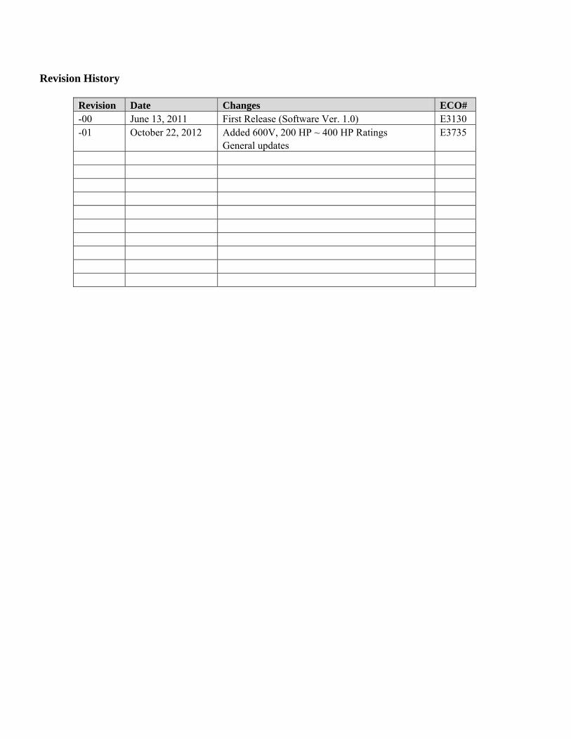
Revision History
Revision Date Changes ECO# -00 June 13, 2011 First Release (Software Ver. 1.0) E3130 -01 October 22, 2012 Added 600V, 200 HP ~ 400 HP Ratings
General updates E3735


BENSHAW615 Alpha DrivePittsburgh, PA 15238Phone: (412) 968-0100Fax: (412) 968-5415
BENSHAW Canada550 Bright StreetListowel, Ontario N4W 3W3Phone: (519) 291-5112Fax: (519) 291-2595
BENSHAWADVANCED CONTROLS & DRIVES