rs507/rs507x quick start guide (en) - idmart.com.tw
TRANSCRIPT

RS507/RS507XHands-Free Imager
Quick Reference Guide

2 RS507/RS507X
WarrantyFor the complete Zebra hardware product warranty statement, go to: www.zebra.com/warranty.
Service Information
If you have a problem using the equipment, contact your facility’s Technical or Systems Support. If there is a problem with the equipment, they will contact the Zebra Support at: www.zebra.com/support.
For the latest version of this guide go to: www.zebra.com/support.

Quick Reference Guide 3
IntroductionThis guide applies to Model Numbers RS507 and RS507X.
The RS507 Hands-Free Imager (also referred to as the Imager) is a wearable barcode scan solution for both 1D and 2D barcode symbologies. The Imager is also compatible with a wide range of mobile computers communicating over Bluetooth.
The Imager is designed for a wide range of applications from management of products in a warehouse, to processing deliveries at a courier facility to processing prescription drugs at the pharmaceutical distribution center.
The Imager uses camera-based scanning technology, designed to offer flexible hands-free operation with ergonomic comfort for right or left hand users.
The Imager can be operated in both manual and auto-triggering modes. Auto-triggering is a patent-pending Intelligent Sensing Technology combining motion and proximity sensing for triggering the Imager.
About this GuideThis guide provides basic information on the following topics:
• Cordless Configuration Features on page 5
• Corded Configuration Features on page 6
• Getting Started - Cordless Configuration on page 8
• Getting Started - Corded Configuration on page 9
• Status Indications on page 11
• Bluetooth Connection on page 12
• Scan on page 13
• Customize the Imager on page 15
• Resetting the Imager on page 16
• Troubleshooting on page 17
• Field Replaceable Parts on page 18
• Cleaning on page 23
For more information, refer to the RS507 Hands-Free Imager Product Reference Guide, p/n 72E-120802-xx available at: www.zebra.com/support.

4 RS507/RS507X
Unpacking the ImagerAfter opening the shipping box, inspect the contents. You should have received the following:
- Standard Range (SR): The SR focusing is used to maximize the far reading distance and is the standard offering on all mobile computing products using same imager. The SR focusing is not specified to read 5 mil code 128 or 6.6 mil Databar and is thus inadequate for applications that have these somewhat higher density reading requirements. This is the default configuration and the configuration of choice where the far reading range is more important than the ability to read high density symbols.
- Driver License (DL): The DL focusing is optimized for reading all drivers license and is also specified to read higher density codes such as 5 mil code 128 and Databar and 5 Mil PDF417. As a result it has a slightly reduced range on EAN/UPC codes (typically 12" on photographic quality symbol). This is the preferred configuration where the ability to read these higher density codes is more important than range on medium or low density codes (10 mil and above). DL is recommended in electronics, pharmacy or when handling small items.
Inspect the equipment for damage. If you are missing any equipment or if you find any damaged equipment, contact Zebra Support immediately at: www.zebra.com/support.
Model
yy:IM = SR focusDL = DL focus
z:blank = RS507 (legacy)
x = RS507X (new)
Desc
riptio
n
Stan
dard
Bat
tery
Exte
nded
Bat
tery
Cord
ed A
dapt
er
Trig
ger
Qui
ck R
efer
ence
Gui
de
RS507z-yy2xxxxSTWR Cordless, triggered RS507 with standard battery
RS507z-yy2xxxxSNWR Cordless, triggerless RS507 with standard battery
RS507z-yy2xxxxENWR Cordless, triggerless RS507 with extended battery.
RS507z-yy2xxxxCTWR Corded and triggered RS507
RS507z-yy2xxxx0TWR Cordless, triggered RS507 with no battery

Quick Reference Guide 5
Cordless Configuration Features
Imager WindowBattery
Battery Release Latch
Finger Strap Scan Trigger
Strap Buckle
Beeper
Restore Key
Left Scan LED
Right Scan LED
Comfort Pad
Trigger Swivel Assembly
Asset Control Label
Triggerless Configuration
Triggerless Strap Holder
Trigger Configuration
6 RS507/RS507X
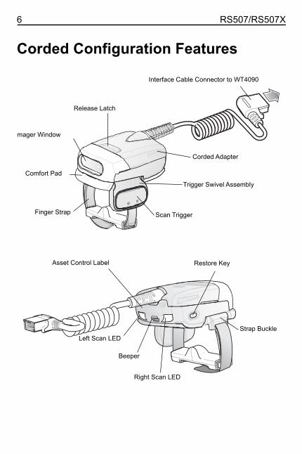
Corded Configuration Features
Release Latch
mager Window
Finger Strap Scan Trigger
Comfort Pad
Corded Adapter
Strap Buckle
Beeper
Restore Key
Left Scan LED
Right Scan LED
Trigger Swivel Assembly
Interface Cable Connector to WT4090
Asset Control Label

Quick Reference Guide 7
Change Trigger PositionThe Trigger Swivel Assembly of the Imager rotates to provide left-hand or right-hand use.
1. From the bottom of the Imager, hold and pull the Comfort Pad out of the Imager.
2. Determine whether the Imager is used on the right or left hand and rotate the Trigger Swivel Assembly.
3. Rotate the Trigger Swivel Assembly so that the Scan Trigger is positioned next to the thumb when the Imager is placed on the index and middle fingers.
4. Position the Comfort Pad onto the Imager.
5. Press the Comfort Pad onto the Imager. When properly installed, the Comfort Pad “locks” into place.
6. Insert the Finger Strap into the Strap Buckle.
CAUTION The Trigger Swivel Assembly only rotates 180° around the bottom of the Imager. Do not rotate the Trigger Swivel Assembly past the designed stops.
Finger Strap
Strap Buckle
Comfort Pad
Trigger Swivel Assembly
Note: It is not necessary to remove the Finger Strap from the Trigger Swivel Assembly.
Trigger Swivel Assembly
Scan Trigger

8 RS507/RS507X
Getting Started - Cordless ConfigurationCharge the BatteryBefore using the Imager, charge the battery. The 8-Bay Battery Charger supports both standard and extended capacity batteries.
To charge the Imager battery, refer to the SAC5070 8-Bay Battery Charger Quick Reference Guide, p/n 72-11589-xx available at: www.zebra.com/support.
Install the Battery1. Align the Battery on top of the Imager.
2. Push the battery all the way into the Locking Slots of the Imager.
3. Firmly press the Battery into the Imager until a “click” is heard ensuring the Battery Release Latch is fully engaged with the Imager.
Remove the Battery1. Hold the Imager in one hand.
2. Press the Battery Release Latch.
3. Pull up the Battery to release from the Locking Slots of the Imager.
Wear the Imager1. Slide the Imager onto the index and middle fingers with the Scan Trigger next
to the thumb.
Locking Slots
Battery
Battery Release Latch
Scan Trigger
Quick Reference Guide 9
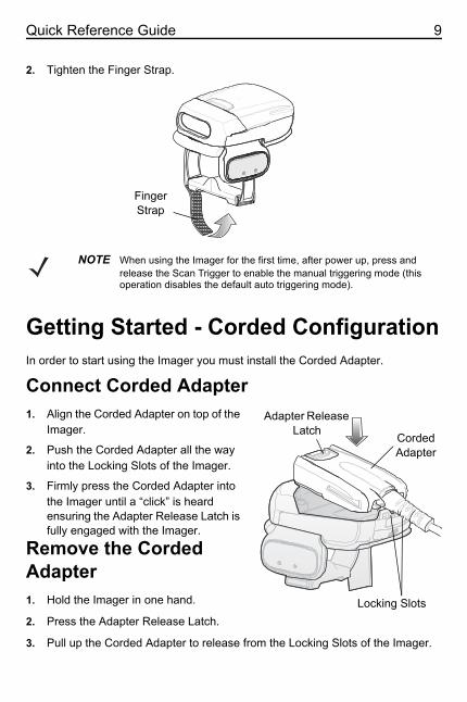
2. Tighten the Finger Strap.
Getting Started - Corded ConfigurationIn order to start using the Imager you must install the Corded Adapter.
Connect Corded Adapter1. Align the Corded Adapter on top of the
Imager.2. Push the Corded Adapter all the way
into the Locking Slots of the Imager.3. Firmly press the Corded Adapter into
the Imager until a “click” is heard ensuring the Adapter Release Latch is fully engaged with the Imager.
Remove the Corded Adapter1. Hold the Imager in one hand.
2. Press the Adapter Release Latch.
3. Pull up the Corded Adapter to release from the Locking Slots of the Imager.
NOTE When using the Imager for the first time, after power up, press and release the Scan Trigger to enable the manual triggering mode (this operation disables the default auto triggering mode).
Finger Strap
Locking Slots
Adapter Release Latch
Corded Adapter

10 RS507/RS507X
Connect to a Wearable TerminalThe Imager connects to a terminal and mounts on the fingers.
To connect the Imager to the terminal:
1. On the terminal, remove the cover from the Terminal Interface Connector.
2. Connect the Interface Cable Connector of the Imager to the Terminal Interface Connector.
To disconnect the Imager from the terminal:
1. Press the Disconnect Button on the Interface Cable Connector.
2. Pull the Interface Cable Connector out of the terminal.
Wear the Imager1. Slide the Imager onto the index and middle fingers with the Scan Trigger next
to the thumb.
2. Tighten the Finger Strap.
NOTE When using the Imager for the first time, press and release the Scan Trigger to enable the manual triggering mode (this operation disables the default auto triggering mode).
Interface Cable Connector
Terminal Interface Connector
Disconnect Button
Scan Trigger
�������������������������������������������������������������������������������������������������������������������������������������������������������������������������������������������������������������������������������������������������������������������������������������������������
�4t×QFinger Strap

Quick Reference Guide 11
Status IndicationsThe Imager has two Scan LEDs that provide identical indications. The Imager is also equipped with a beeper that generates sound indications in variable tones.
NOTE In the corded configuration, beep indications are emitted only from the connected terminal.
No. LED Beep Indication Description1. None High/low Bluetooth communication is
disconnected.2. Short green
flashesNone Attempting to connect over
Bluetooth.3. None Low/high Imager is connected over
Bluetooth.4. None High/low Bluetooth communication is
disconnected - Imager is out of range.
5. None high/low/high/low Properly decoded scan of Bluetooth pairing barcode.
6. None Long low/long high/
Bluetooth connection attempt failed.
7. None Long low/long high/Long low/long high/
Bluetooth connection attempt is rejected.
8. One green flash
High Proper scanning indication.
9. None 4 long beeps No Bluetooth communication after reconnection failure.
10 Red flash 2 short beeps Low battery.11 Long red
flash followed by a green flash
High/lowHigh/low
Clean boot was performed successfully.

12 RS507/RS507X
Bluetooth ConnectionEstablish Bluetooth ConnectionTo establish Bluetooth connection with a mobile computer:
1. Ensure that the Imager is within a range of 10 meters (30 feet) from the mobile computer.
2. Install the battery in the Imager.
3. Launch the Bluetooth Device (BD) Address application on the mobile computer. Most BD Address applications display a pairing barcode image on the screen of the mobile computer.
4. Scan a pairing barcode from the mobile computer screen or a provided label. The Imager emits one string of high/low/high/low beeps.
5. The Scan LED starts flashing green indicating that the Imager is attempting to establish connection with a mobile computer.
6. When connection is established, the Scan LED turns off and the Imager emits one string of low/high beeps. The Imager is connected and ready for scanning.
Remove Bluetooth Connection
1. Scan an unpairing barcode label for disconnecting the Imager from the mobile computer.
2. The Imager emits one string of high/low beeps indicating that Bluetooth communication with the mobile computer is disconnected.
Restore Lost Bluetooth ConnectionThe Imager maintains Bluetooth communication with a mobile computer within a range of 10 meters (30 feet). When the Imager fails to establish connection or connection is lost during operation, the Imager emits one string of low/high beeps.
To reestablish the Bluetooth connection with a mobile computer:
1. Ensure that the Imager is within a range of 10 meters (30 feet) from the mobile computer.
NOTE When replacing the Imager battery, the Imager memory retains the pairing information of the last paired mobile computer.
NOTE Removing Bluetooth connection is only required if the Imager is configured for auto-connect on power on and has to be paired with a different terminal.

Quick Reference Guide 13
2. Ensure that the mobile computer is “on and awake” (not in Suspend mode).
3. The Imager automatically attempts reconnecting to the mobile computer for 30 seconds (Scan LED flashes green). If automatic re-connection fails, verify that the Imager is within Bluetooth range and briefly press the Restore Key on the Imager to reconnect.
4. The Scan LED starts flashing green indicating that the Imager is attempting to establish connection with a mobile computer.
5. The Scan LED turns off and the Imager emits one string of low/high beeps indicating that the Imager is connected and ready for scanning.
ScanThe Imager uses digital camera technology to take an image of a barcode and software decoding algorithms are executed to extract the barcode data from the image.
Scan Triggering ModesManual Triggering (Triggered models only)
1. Launch a scanning software application on the mobile computer.
2. Position the Imager approximately 9 inches (22.8 cm) from a barcode label and press the Scan Trigger. Position the cross hair laser beam to cover the barcode. The Imager takes a digital picture (image) of the barcode and stores it in memory for decoding.
3. One green flash and a high beep sounds to indicate that the barcode was properly decoded.
Auto-triggering (Triggerless models only)
The Imager is provided with auto-triggering capability. In auto-triggering mode, both motion and proximity sensors are used to trigger the Imager when the user intends to scan a barcode.
With auto-triggering activated, the Imager automatically scans when motion stops and a barcode is placed within the depth of field of the Imager. The Imager scans the barcode and turns off to conserve power. The Imager can also be configured
NOTE After battery is inserted or a corded adaptor is connected (on both sides), the first trigger press disables the auto triggering mode.
NOTE In some applications, proper decoding of a barcode is indicated by a software application running on the mobile computer.
14 RS507/RS507X
to a single or continued scan operation. The motion and proximity features are enabled by default and can be re-configured by the user (see RS507 Hands-Free Imager Product Reference Guide, p/n 72E-120802-xx).
To scan a barcode in auto-triggering mode:
1. Position the Imager approximately 9 inches (22.8 cm) from a barcode label.
2. Hold the Imager steady, aiming at the barcode.
3. The Imager takes a picture (image) of the barcode and stores it in memory for decoding.
4. One green flash of the Scan LED and a high beep indicates that a barcode was properly decoded.
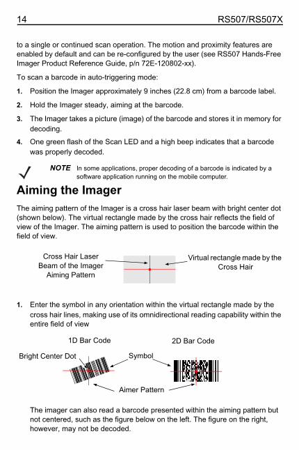
Aiming the ImagerThe aiming pattern of the Imager is a cross hair laser beam with bright center dot (shown below). The virtual rectangle made by the cross hair reflects the field of view of the Imager. The aiming pattern is used to position the barcode within the field of view.
1. Enter the symbol in any orientation within the virtual rectangle made by the cross hair lines, making use of its omnidirectional reading capability within the entire field of view
The imager can also read a barcode presented within the aiming pattern but not centered, such as the figure below on the left. The figure on the right, however, may not be decoded.
NOTE In some applications, proper decoding of a barcode is indicated by a software application running on the mobile computer.
Virtual rectangle made by the Cross Hair
Cross Hair Laser Beam of the Imager
Aiming Pattern
2D Bar Code1D Bar Code
Symbol
Aimer Pattern@123
4@Bright Center Dot

Quick Reference Guide 15
2. Hold the Imager between two and eleven inches from the barcode (depending on the barcode density).
3. Press the Scan Button. The aiming pattern illuminates red indicating that the laser is on. One green flash of the Scan LED and a high beep indicates that a barcode was properly decoded.
Customize the ImagerChanging from Trigger to Triggerless ConfigurationTo Change from Trigger to Triggerless configuration:
1. Remove the Comfort Pad (See Comfort Pad Replacement on page 19).
2. Remove the Trigger Swivel Assembly (See Trigger Swivel Assembly Replacement on page 20).
3. Install the Triggerless Strap Holder (See Triggerless Strap Holder Replacement on page 21).
4. Install the Comfort Pad (See Comfort Pad Replacement on page 19).
5. Perform a cold boot (See Cold Boot on page 16).
Changing Triggerless to Trigger ConfigurationTo change from Triggerless to Trigger configuration:
1. Remove the Comfort Pad (See Comfort Pad Replacement on page 19).
2. Remove the Triggerless Strap Holder (See Finger Strap Replacement (Triggerless Strap Holder) on page 22).
NOTE When using the application on your mobile computer in “Pick List” mode, the Bright Center Dot can be positioned anywhere on the symbol.
The aiming pattern is smaller when the Imager is closer to the symbol and larger when it is farther from the symbol. Scan symbols with smaller bars or elements (mil size) closer to the Imager and those with larger bars or elements (mil size) farther from the Imager.
NOTE When a symbol is under transparent plastic or on a mobile computer screen, it is recommended to use a tilt (pitch) or skew scan angle to avoid reflection.
@1234@ @1234@WrongRight

16 RS507/RS507X
3. Install the Trigger Swivel Assembly (See Trigger Swivel Assembly Replacement on page 20).
4. Install the Comfort Pad (See Comfort Pad Replacement on page 19).
5. Perform a cold boot (See Cold Boot on page 16).
6. Press and release the Scan Trigger to enable the manual triggering mode (this operation disables the default Triggerless mode).
Resetting the ImagerIf the Imager stops responding to an input, perform a cold boot.
To restore the Imager to its factory default configuration, perform a clean boot.
Cold BootCold boot restores the Imager operation by resetting its software. To perform a cold boot, remove and re-insert the battery into the Imager. When using a corded Imager model with WT4XXX, remove and reconnect the interface cable that connects between the Imager and the WT4XXX.
Clean BootClean boot restores the Imager to its factory default configuration.
To perform clean boot:
1. Remove the battery or Corded Adapter from the Imager.
2. Press and hold the Restore Key.
3. Insert the Battery or Corded Adapter to the Imager.
4. Keep holding the Restore Key pressed for about five seconds until a chirp is heard and the Scan LEDs flash green. The Imager is now in its factory default configuration.
NOTE When the Imager is used with the WT4XXX, Triggerless mode can also be disabled from the WT4XXX.

Quick Reference Guide 17
TroubleshootingProblem Cause Solution
Laser aiming pattern does not display when pressing the Scan Trigger.
Corded: Interface cable is not secure.Cordless: Battery is not charged.
Verify that the interface cable is properly connected.
Replace or charge the battery.Power is not applied to Imager.
Corded: Verify that the mobile computer has a charged battery installed.
Cordless: Replace or Charge Imager battery.
Scan application on the mobile computer is not functioning.
Restart the scanning application on the mobile computer.
Imager software does not respond.
Reset the Imager (See Resetting the Imager on page 16).
Imager does not decode a barcode.
Bar code is unreadable.
Verify that the barcode is not defective, i.e., smudged or damaged.
Exit window is dirty. Clean exit window with a lens tissue. Tissues for eyeglasses work well. Do not use tissues coated with lotion.
Bar code symbology is not supported or enabled.
See your system administrator.
Cordless: Bluetooth link is disconnected.
Reestablish Bluetooth connection (See Establish Bluetooth Connection on page 12).

18 RS507/RS507X
Field Replaceable PartsPart Description
1 KT-CLMPT-RS507-01R Trigger Swivel Assembly.
2 KT-BKL-RS507-10R Set of 10 Buckles for Hook and Loop Strap.
3 KT-BKLN-RS507-10R Set of 10 Buckles for Triggerless Elastic Finger Strap.
4 KT-BKLT-RS507-10R Set of 10 Buckles for Trigger Elastic Finger Strap.
5 KT-CLMPN-RS507-01R Triggerless Strap Holder.
6 KT-PAD-RS507-10R Set of 10 Trigger Comfort Pads.
7 KT-PAD2-RS507-10R Set of 10 Triggerless Comfort Pads. M2 Screw Included.
8 KT-STRPN-RS507-10R Set of 10 Triggerless Finger Strap.
9 KT-STRPT-RS507-10R Set of 10 Trigger Finger Strap.
10 KT-STRP2-RS507-10R Set of 10 Trigger or Triggerless Elastic Strap.
11 KTBTRYRS50EAB00-01 Standard Battery.
12 KTBTRYRS50EAB02-01 Extended Battery.
13 ADPTRWT-RS507-04R Corded Adapter.
KT-ESTRPTRS507-10R Set of 10 Elastic Straps with Buckles for Trigger and Triggerless configurations.
12 5
1098
11 12 13
Finger Support
3 & 4
67
M2 Screw

Quick Reference Guide 19
Comfort Pad ReplacementRemoval1. Flip the Imager over, such that the bottom of the
Imager and the Comfort Pad are facing upwards.2. On a Triggerless Strap Holder, use a flat
screwdriver to remove the M2 screw.3. Insert the tip of your finger under the edge of the
Comfort Pad at the back of the Imager.4. Lift the Comfort Pad upwards and remove it from
the Imager.
Installation
1. Position the Comfort Pad onto the Imager as shown.
2. Press the Comfort Pad onto the Imager. When properly installed, the Comfort Pad locks into place.
3. On a Triggerless Swivel Assembly, use a flat screwdriver to install the M2 screw.
CAUTION Removing the Comfort Pad other than the described above may result in damage to the Trigger Swivel Assembly of the Imager.
NOTE The Trigger Comfort Pad can only be installed on a Trigger Swivel Assembly.
The Triggerless Comfort Pad can be installed on a Trigger Swivel Assembly without the M2 screw.
Trigger Swivel Assembly
Triggerless Strap Holder

20 RS507/RS507X
Trigger Swivel Assembly ReplacementRemoval1. Turn the Imager upside-down.
2. Remove the Comfort Pad.
3. Use a paper clip or similar object to press the Release Latch.
4. Rotate the Trigger Swivel Assembly (or Triggerless Strap Holder) toalign with the back of the Imager.
5. Lift the Trigger Swivel Assembly off the Imager.
Installation1. Turn the Imager upside-down.
2. Position the Trigger Swivel Assembly to align with the back of the Imager.
3. Lower the Trigger Swivel Assembly to the Imager.
4. Rotate Trigger Swivel Assembly 1/4 turn counterclockwise.
5. Press the Comfort Pad onto the Imager. When properly installed, the Comfort Pad “locks” into place.
NOTE An optional Triggerless Strap Holder should be installed when the Imager is intended to be used in Motion and Proximity Initiated Bar code Read mode.
1
2
3
Release Latch
Imager Back
Trigger SwivelAssembly
1
2

Quick Reference Guide 21
Triggerless Strap Holder ReplacementRemoval1. Turn the Imager upside-down.
2. Remove the Comfort Pad.
3. Use a paper clip or similar object to press the Release Latch.
4. Rotate the Triggerless Strap Holder to align with the back of the Imager.
5. Lift the Triggerless Strap Holder off the Imager.
Installation1. Turn the Imager upside-down.
2. Position the Triggerless Strap Holder to align with the back of the Imager.
3. Lower the Triggerless Strap Holder to the Imager.
4. Rotate Triggerless Strap Holder 1/4 turn counterclockwise.
1
2
3
Release Latch
Imager Back
Triggerless Strap Holder
1
2

22 RS507/RS507X
Finger StrapReplacement (Trigger Swivel Assembly)Removal1. Remove the Finger Strap from
the Strap Buckle.2. Pull the Finger Strap out of the
Trigger Swivel Assembly.Installation1. Align a new Finger Strap with the
Slots in the Trigger Swivel Assembly.
2. Gently press the Strap Pins to engage with the slots of the Trigger Swivel Assembly. The Strap Pins snap into the slots.
3. Slip the Finger Strap through the Strap Buckle.
Finger Strap Replacement (Triggerless Strap Holder)RemovalRemove the Finger Strap from the Strap Buckles.
InstallationSlip the Finger Strap through the Strap Buckles.
Strap Pins
Slots
Finger Strap
Trigger Swivel Assembly
Strap Buckle
Strap Buckles
Triggerless Strap Holder
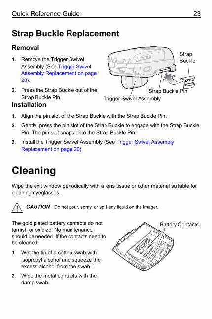
Quick Reference Guide 23
Strap Buckle ReplacementRemoval1. Remove the Trigger Swivel
Assembly (See Trigger Swivel Assembly Replacement on page 20).
2. Press the Strap Buckle out of the Strap Buckle Pin.
Installation1. Align the pin slot of the Strap Buckle with the Strap Buckle Pin.
2. Gently, press the pin slot of the Strap Buckle to engage with the Strap Buckle Pin. The pin slot snaps onto the Strap Buckle Pin.
3. Install the Trigger Swivel Assembly (See Trigger Swivel Assembly Replacement on page 20).
CleaningWipe the exit window periodically with a lens tissue or other material suitable for cleaning eyeglasses.
The gold plated battery contacts do not tarnish or oxidize. No maintenance should be needed. If the contacts need to be cleaned:
1. Wet the tip of a cotton swab with isopropyl alcohol and squeeze the excess alcohol from the swab.
2. Wipe the metal contacts with the damp swab.
CAUTION Do not pour, spray, or spill any liquid on the Imager.
Strap Buckle
Strap Buckle Pin Trigger Swivel Assembly
Battery Contacts

© 2017 ZIH Corp and/or its affiliates. All rights reserved. Zebra and the stylized Zebra head are trademarks of ZIH Corp., registered in many jurisdictions worldwide. All other trademarks are the property of their respective owners. MN-002936-02 Rev. A - 12/17
www.zebra.com