rs232/485 radio modem typhoon
TRANSCRIPT

DS500-1 Jan 2008 ©2008 Reg. No. 227 4001, ENGLAND Page 1
TYPHOON RS232/485 RADIO MODEM
• Wireless half duplex radio modem
• RS232 and RS485 serial interfaces
• RF power up to 500mW (+27dBm)
• Range up to 4km1
• Radio baud rate up to 38.4kbps
• Serial baud rate up to 115.2kb/s
• Housed in a tough ABS enclosure rated IP68
• Multiple radio channel operation2
• European 869.400 to 869.650 MHz operation
• Requires no radio licence to operate
• Powered from 9 to 12Vdc
• Internal LED indication of power and communications
• Configurable with standard Hayes AT commands
Applications
• Wireless data logging
• CCTV control
• RS232 or RS485 serial cable replacement
• Machine to machine data communications
Description The RF Solutions typhoon RF modem provides fast and reliable wireless data communications at an exceptionally competitive price. Whilst the RF modem is simple to use it is also highly adaptable and can be used in a wide variety of applications.
The RF modem is configurable as a ‘transparent’ wireless serial point-to-point link, reproducing the function of a half duplex serial cable. An addressed secured mode is also supported.
The RF modem can be configured to scan the radio link for activity and verify it is free before transmission thereby avoiding data collisions.
Supplied in a tough IP68 rated ABS enclosure, with an RS232 cable and antenna, the RF modem requires only a 9 to 12Vdc (1A maximum) power supply to function.
1 Range stated is optimum in direct line of sight. Operational range may be significantly reduced in areas with obstructions or
interference. 2 Maximum power output is reduced when used in multi channel mode.
RF ModemRS232/485
Antenna
Power Supply
CTSRXTX
PWRRTS

DS500-1 Jan 2008 ©2008 Reg. No. 227 4001, ENGLAND Page 2
TYPHOON RS232/485 RADIO MODEM
Contents 1 Technical Specification.............................................................................................................. 3
1.1 Functional description ........................................................................................................ 3
1.2 Functional Characteristics.................................................................................................. 3
1.2.1 General ....................................................................................................................... 3
1.2.2 Transmission............................................................................................................... 3
1.2.3 Reception.................................................................................................................... 4
1.2.4 DC............................................................................................................................... 4
1.3 Status LEDs ....................................................................................................................... 4
1.4 Power Supply ..................................................................................................................... 4
1.5 Host Interface..................................................................................................................... 5
1.5.1 Serial Link Mode Selection ......................................................................................... 5
1.5.2 RS232 Serial Link ....................................................................................................... 5
1.5.3 RS485 Serial Link ....................................................................................................... 6
1.5.4 RS232/485 Slew Rate................................................................................................. 6
1.6 Antenna .............................................................................................................................. 7
1.7 Temperature Range ........................................................................................................... 7
1.8 Dimensions......................................................................................................................... 7
2 Software Specification............................................................................................................... 8
2.1 Quick Setup Guide ............................................................................................................. 8
3 Operating Modes....................................................................................................................... 9
3.1 Hayes or ‘AT’ Mode............................................................................................................ 9
3.1.1 Standard Commands Description............................................................................... 9
3.2 Transparent Mode............................................................................................................ 10
3.3 Addressed Secured mode................................................................................................ 10
4 Register Definitions ................................................................................................................. 13
4.1 Radio ................................................................................................................................ 13
4.2 RS-232/485 Serial Link .................................................................................................... 14
4.3 Operation and Power Settings ......................................................................................... 15
4.4 Network Control ............................................................................................................... 15
4.5 Radio Test Commands .................................................................................................... 16
5 Ordering Information ............................................................................................................... 16
DS500-1 Jan 2008 ©2008 Reg. No. 227 4001, ENGLAND Page 3
TYPHOON RS232/485 RADIO MODEM
1 Technical Specification
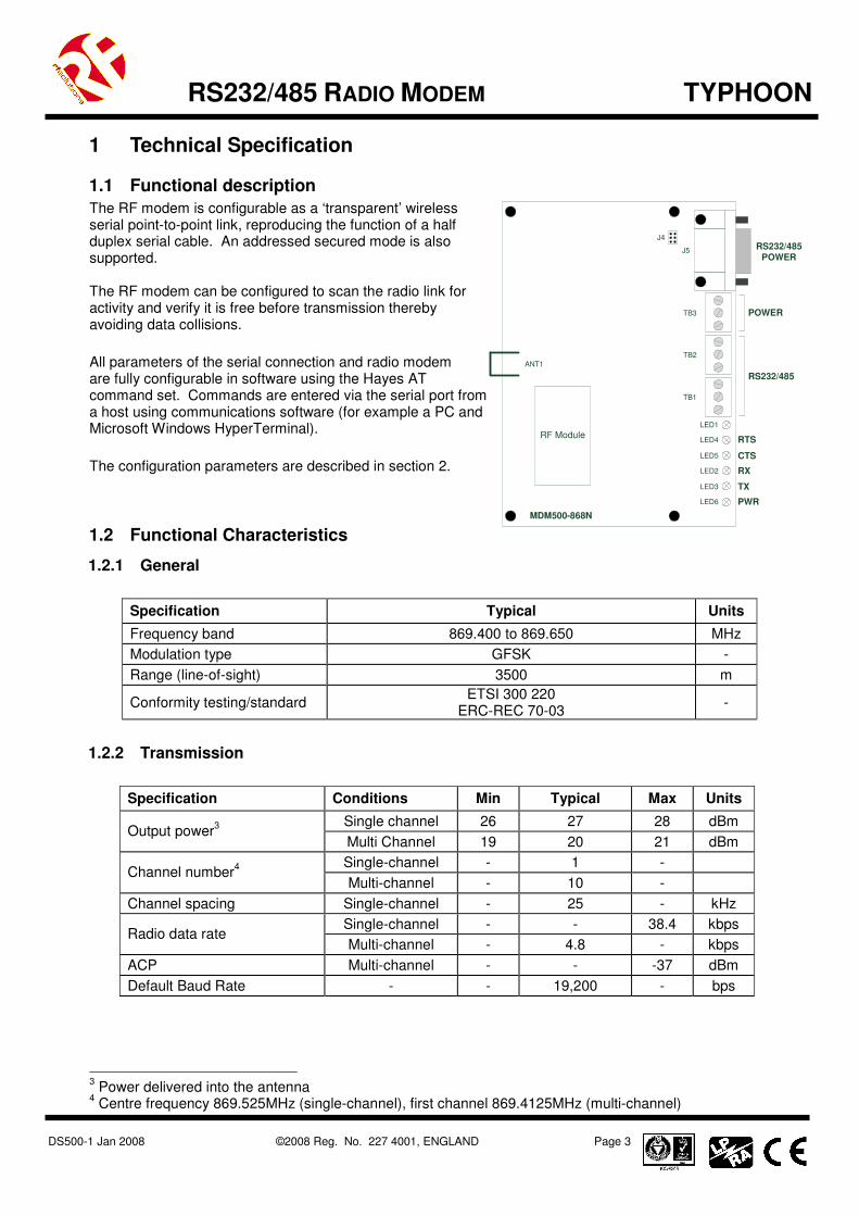
1.1 Functional description
The RF modem is configurable as a ‘transparent’ wireless serial point-to-point link, reproducing the function of a half duplex serial cable. An addressed secured mode is also supported. The RF modem can be configured to scan the radio link for activity and verify it is free before transmission thereby avoiding data collisions.
All parameters of the serial connection and radio modem are fully configurable in software using the Hayes AT command set. Commands are entered via the serial port from a host using communications software (for example a PC and Microsoft Windows HyperTerminal).
The configuration parameters are described in section 2.
1.2 Functional Characteristics
1.2.1 General
Specification Typical Units
Frequency band 869.400 to 869.650 MHz
Modulation type GFSK -
Range (line-of-sight) 3500 m
Conformity testing/standard ETSI 300 220
ERC-REC 70-03 -
1.2.2 Transmission
Specification Conditions Min Typical Max Units
Single channel 26 27 28 dBm Output power
3
Multi Channel 19 20 21 dBm
Single-channel - 1 - Channel number
4
Multi-channel - 10 -
Channel spacing Single-channel - 25 - kHz
Single-channel - - 38.4 kbps Radio data rate
Multi-channel - 4.8 - kbps
ACP Multi-channel - - -37 dBm
Default Baud Rate - - 19,200 - bps
3 Power delivered into the antenna
4 Centre frequency 869.525MHz (single-channel), first channel 869.4125MHz (multi-channel)
PWR
TX
RX
CTS
RTSRF Module
LED6
LED3
LED2
LED5
LED4
LED1
TB1
TB2
TB3
J5
ANT1
RS232/485
POWER
RS232/485POWER
J4
MDM500-868N

DS500-1 Jan 2008 ©2008 Reg. No. 227 4001, ENGLAND Page 4
TYPHOON RS232/485 RADIO MODEM
1.2.3 Reception
Specification Conditions Min Typical Max Units
Single-channel -98 -100 -102 dBm Sensitivity for CER <10
-3
Multi-channel -103 -105 -107 dBm
Average CER Input signal
-50 dBm - <1.10
-6 - -
Saturation for CER <10-3
Under 50Ω - - -10 dBm
Selectivity Multi-channel
between channels - 30 - dB
Immunity against adjacent channels
Multi-channel Jammer -20dBm
20 - - dB
Immunity against other channels
Multi-channel Jammer -20dBm
30 - - dB
Immunity against spurious out of band channels
Single and multi-channel
- 40 - dB
Below 1GHz - - -57 dBm Spurious leakage
Above 1GHz - - -47 dBm
1.2.4 DC
Specification Conditions Min Typical Max Units
Power supply Ripple <50mV 6.5V 12V 13.2 V
Transmit (27dBm/500mW)
- 679 - mA Current consumption
Receive - 58 - mA
1.3 Status LEDs
The RF Modem has several LEDs that represent the status of the power supply and data and data transmissions as follows:
• TX – On when transmitting data over the air
• RX – On when receiving data over the air
• CTS – On with Clear To Send
• RTS – On with signal Ready To Send
• PWR – On when the power supply is healthy
1.4 Power Supply
The RF Modem is powered from a 9 to 12Vdc power supply which must be capable of providing current up to 1A. Connections are made using either TB3 or J5 as follows:
Pin Connection
5 0V (ground)
9 9 to 12Vdc,
1A max
Pin Connection
1 0V (ground)
2 0V (ground)
3 9 to 12Vdc,
1A max
TB3
POWER
1 2 3 Cable entry
DS500-1 Jan 2008 ©2008 Reg. No. 227 4001, ENGLAND Page 5
TYPHOON RS232/485 RADIO MODEM
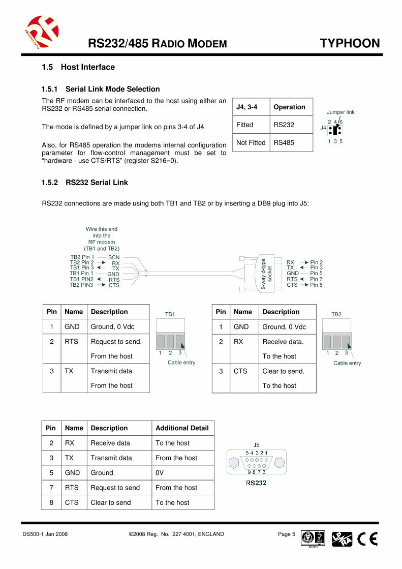
1.5 Host Interface
1.5.1 Serial Link Mode Selection
The RF modem can be interfaced to the host using either an RS232 or RS485 serial connection.
The mode is defined by a jumper link on pins 3-4 of J4.
Also, for RS485 operation the modems internal configuration parameter for flow-control management must be set to “hardware - use CTS/RTS” (register S216=0).
1.5.2 RS232 Serial Link
RS232 connections are made using both TB1 and TB2 or by inserting a DB9 plug into J5:
9-way d-type
socket
Wire this end
into the
RF modem
(TB1 and TB2)
RXTX
GNDRTSCTS
RXTX
RTSCTS
GND
Pin 2Pin 3
Pin 7Pin 8
Pin 5
TB2 Pin 2TB1 Pin 3
TB1 PIN2TB2 PIN3
TB1 Pin 1
SCNTB2 Pin 1
Pin Name Description Additional Detail
2 RX Receive data To the host
3 TX Transmit data From the host
5 GND Ground 0V
7 RTS Request to send From the host
8 CTS Clear to send To the host
J4, 3-4 Operation
Fitted RS232
Not Fitted RS485
Pin Name Description
1 GND Ground, 0 Vdc
2 RX Receive data.
To the host
3 CTS Clear to send.
To the host
TB2
1 2 3
Cable entry
Pin Name Description
1 GND Ground, 0 Vdc
2 RTS Request to send.
From the host
3 TX Transmit data.
From the host
TB1
1 2 3
Cable entry
Jumper link
J4
1 3 5
2 4 6

DS500-1 Jan 2008 ©2008 Reg. No. 227 4001, ENGLAND Page 6
TYPHOON RS232/485 RADIO MODEM
1.5.3 RS485 Serial Link
RS485 connections are made using both TB1 and TB2 or by inserting a DB9 serial cable into J5.
9-way d-type
socket
Pin Name Description Pin Name Description
1 GND Ground, 0Vdc 1 GND Ground, 0Vdc
2 TXB Transmit data ‘-‘
From the host
2 RXB Receive data ‘-‘
To the host
3 TXA Transmit data ‘+’
From the host
3 RXA Receive data ‘+’
To the host
TB2
1 2 3
Cable entry
Pin Name Description Additional Detail
2 RXB Receive data ‘-’ To the host
8 RXA Receive data ‘+’ To the host
5 GND Ground 0V
3 TXA Transmit data ‘+’ From the host
7 TXB Transmit data ‘-’ From the host
1.5.4 RS232/485 Slew Rate
When using the RF modem in a noisy environment it may beneficial to limit the slew rate of the RS232 / RS485 interface to improve the noise immunity of the wired link. The slew rate is set by a jumper on pins 5-6 of J4.
J4, 5-6 Operation
Fitted Limit Slew Rate
Not Fitted Normal Operation
Jumper link
J4
1 3 5
2 4 6

DS500-1 Jan 2008 ©2008 Reg. No. 227 4001, ENGLAND Page 7
TYPHOON RS232/485 RADIO MODEM
1.6 Antenna
The RF modem is supplied with an 868MHz ¼ wave whip antenna that has been carefully matched to the impedance of the RF modem’s power amplifier
5.
1.7 Temperature Range
Storage temperature: -40˚C to +85
˚C
Operating temperature
6: -10
˚C to +55
˚C
1.8 Dimensions
The RF modem is supplied in an IP68 rated enclosure having the following dimensions. Enclosure dimensions
7: Height 144mm
Width 168mm Depth 85mm
PCB dimensions: 125mm x 90mm x 1.6mm
5 It is the user’s responsibility to ensure that an external antenna if added does not affect this products
suitability to operate within the 868MHz ISM band to the relevant standards 6 Operation at maximum ratings for extended periods may affect the reliability of this product
7 All dimensions are approximate and exclude the antenna and any fixings

DS500-1 Jan 2008 ©2008 Reg. No. 227 4001, ENGLAND Page 8
TYPHOON RS232/485 RADIO MODEM
2 Software Specification
2.1 Quick Setup Guide
The RF modem is supplied with its registers set to their default values. Using the default settings it can quickly and easily be used, from a PC running the Microsoft Windows operating system, to establish a simple transparent point-to-point link. The bundled MTC workbench software can be used by following the steps outlined below.
1. Install the MTC workbench software, supplied on the bundled CD onto your PC.
2. Connect your modem to the COM port of your PC using the supplied RS232 cable, apply power to the modem and load the MTC workbench software. The PWR and RTS LEDs will now be on.
3. When prompted to launch auto-configuration select ‘No’.
4. In the Settings menu change the user level to advanced. From the Modem menu Serial port configuration and select 19,000bps.
5. From the Tools menu select Terminal and open a terminal window on the COM port connected to the modem. You can now type text into the terminal window, if the Port is opened (By pressing the ‘Open Port’ button) then the text data will be sent over the serial link to the modem, as shown opposite.
6. Repeat steps 1-5 using either another PC or a different COM port on the same PC.
7. If the configuration settings are the same for both modems then you should now be able to wirelessly send text from one COM port to the other.
Notes For full instructions on the use of the MTC workbench software please refer the manual provided on the CD bundled with the modems. The modems configuration settings can be changed by double clicking on the modem name, ‘B868-tiny’ under the COM port in the tree window. Once you have changed the settings to those which you require they can be propagated through to the modems registers by clicking on the Apply button. You can also change the configuration settings by entering AT commands into the terminal window in MTC workbench. Please refer to the sections for a description of the AT commands available.
DS500-1 Jan 2008 ©2008 Reg. No. 227 4001, ENGLAND Page 9
TYPHOON RS232/485 RADIO MODEM
3 Operating Modes The RF modem is able to operate in several different modes which can be configured by setting the values of the appropriate special registers using AT commands.
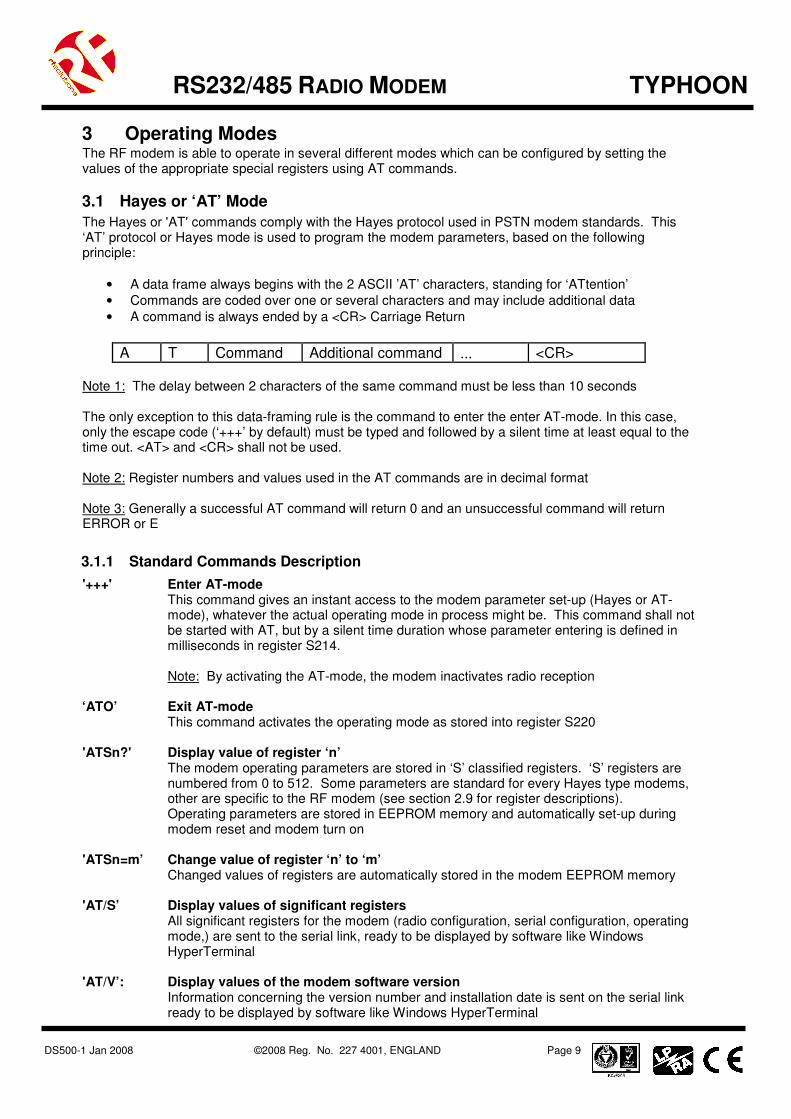
3.1 Hayes or ‘AT’ Mode
The Hayes or 'AT' commands comply with the Hayes protocol used in PSTN modem standards. This ‘AT’ protocol or Hayes mode is used to program the modem parameters, based on the following principle:
• A data frame always begins with the 2 ASCII ’AT’ characters, standing for ‘ATtention’
• Commands are coded over one or several characters and may include additional data
• A command is always ended by a <CR> Carriage Return
A T Command Additional command ... <CR>
Note 1: The delay between 2 characters of the same command must be less than 10 seconds The only exception to this data-framing rule is the command to enter the enter AT-mode. In this case, only the escape code (‘+++’ by default) must be typed and followed by a silent time at least equal to the time out. <AT> and <CR> shall not be used. Note 2: Register numbers and values used in the AT commands are in decimal format Note 3: Generally a successful AT command will return 0 and an unsuccessful command will return ERROR or E
3.1.1 Standard Commands Description
'+++' Enter AT-mode This command gives an instant access to the modem parameter set-up (Hayes or AT-mode), whatever the actual operating mode in process might be. This command shall not be started with AT, but by a silent time duration whose parameter entering is defined in milliseconds in register S214. Note: By activating the AT-mode, the modem inactivates radio reception
‘ATO’ Exit AT-mode
This command activates the operating mode as stored into register S220
'ATSn?' Display value of register ‘n’ The modem operating parameters are stored in ‘S’ classified registers. ‘S’ registers are numbered from 0 to 512. Some parameters are standard for every Hayes type modems, other are specific to the RF modem (see section 2.9 for register descriptions). Operating parameters are stored in EEPROM memory and automatically set-up during modem reset and modem turn on
'ATSn=m’ Change value of register ‘n’ to ‘m’ Changed values of registers are automatically stored in the modem EEPROM memory
'AT/S’ Display values of significant registers
All significant registers for the modem (radio configuration, serial configuration, operating mode,) are sent to the serial link, ready to be displayed by software like Windows HyperTerminal
'AT/V’: Display values of the modem software version
Information concerning the version number and installation date is sent on the serial link ready to be displayed by software like Windows HyperTerminal

DS500-1 Jan 2008 ©2008 Reg. No. 227 4001, ENGLAND Page 10
TYPHOON RS232/485 RADIO MODEM
'ATR’: Hayes registers reset to default values
This command allows the user to reset ALL the stored EEPROM registers to their default values (see section 2.9 for register descriptions)
'ATP’: Switch to Stand-by mode This command allows the user to switch to stand-by mode. The modem is in normal mode by default. The modem switches back to normal node with a character reception from the serial link
'ATN’: RSSI interrogation ‘ATN’ command runs the received RF level measurements. The RSSI reading is continuously displayed each second until a new character arrives on the serial link. 4 levels are available: - ‘0’ : received level < -90dBm - ‘1’ : received level between -90 and -85dBm - ‘2’ : received level between -85 and -80dBm - ‘3’ : received level > -80dBmThis command allows the user to switch to Stand-by mode. The modem is in normal mode by default. The modem switches back to normal mode with a character reception on the serial link
3.2 Transparent Mode
This is the default operating mode. Data is transferred transparently, without encapsulation, flow control or addressing. I.e. all data sent onto the serial port by the host is transmitted across the radio link by the RF modem and will be intercepted by any similarly configured modems.
In this mode the RF modem appears as a wireless serial point-to-point link, reproducing the function of a half duplex serial cable
8.
It can also be configured to scan the radio link for activity and verify it is free before transmission (listen before talk) thereby avoiding data collisions.
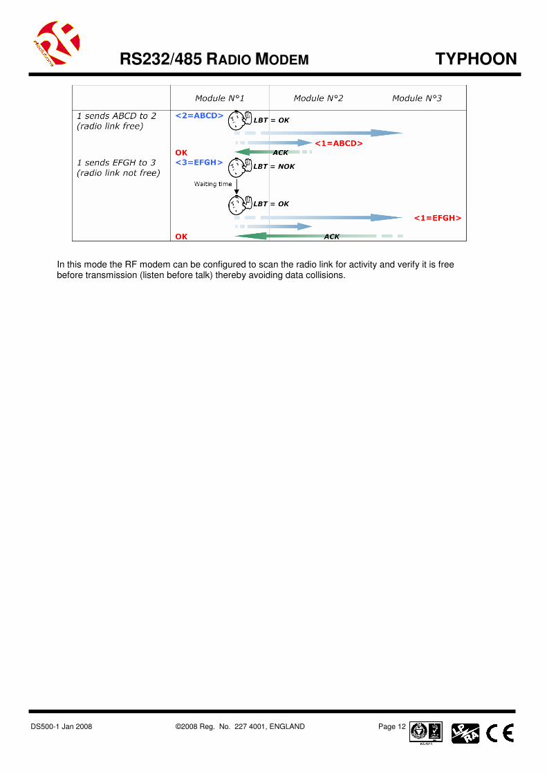
3.3 Addressed Secured mode
This is a simplified multipoint network protocol where a network of modems allows one modem to communicate with any other. All data transfers are encapsulated, addressed and have flow control (i.e. frames are checked using CRC then acknowledged).
8 The user’s software application must verify that all buffers are transmitted correctly taking into account
that an interrupted transmission link may lead to losing one or several buffers

DS500-1 Jan 2008 ©2008 Reg. No. 227 4001, ENGLAND Page 11
TYPHOON RS232/485 RADIO MODEM
This mode’s purpose is to offer optimal radio link quality with secure data transfer and as such includes an address field so that it is possible to address a particular modem within a network. Key points are as follows:
• Data transmissions are fully «data verified»
• The modem acts as in transparent mode, adding frame encapsulation
• Each modem has an address
• Identification of a particular modem is enabled by adding that modems “address” at the beginning of each data frame
• Maximum number of modems per network = 65535
• Maximum number of networks = 65535
• The data frame format is configured using register S255 Example: "1=Hello" sends the data frame "Hello" to modem with address 1
• The modem with address ‘1’ recognises the client transmitting modem by the number starting the data frame.
Example: "002=Hello" indicates that data frame "Hello" comes from Client No.2. o
• You can add one frame ending character: Carriage Return<CR>, after each received frame. This in order to distinguish each frame.
Example: "002=1458<CR> 003=4587<CR>" indicates data frame "1458" comes from Client No.2, and data frame "4587" comes from Client No.3.
• No server, each client can communicate with each other.
• Maximum of clients per network = 255, maximum of networks = 65535.
• The data frame format can be configured (client ID at beginning, CR at end, Adcon modems frame format compatibility) via register S255.
DS500-1 Jan 2008 ©2008 Reg. No. 227 4001, ENGLAND Page 12
TYPHOON RS232/485 RADIO MODEM
In this mode the RF modem can be configured to scan the radio link for activity and verify it is free before transmission (listen before talk) thereby avoiding data collisions.
DS500-1 Jan 2008 ©2008 Reg. No. 227 4001, ENGLAND Page 13
TYPHOON RS232/485 RADIO MODEM
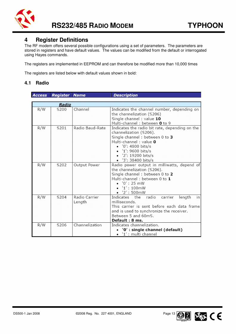
4 Register Definitions The RF modem offers several possible configurations using a set of parameters. The parameters are stored in registers and have default values. The values can be modified from the default or interrogated using Hayes commands. The registers are implemented in EEPROM and can therefore be modified more than 10,000 times The registers are listed below with default values shown in bold:
4.1 Radio
DS500-1 Jan 2008 ©2008 Reg. No. 227 4001, ENGLAND Page 14
TYPHOON RS232/485 RADIO MODEM
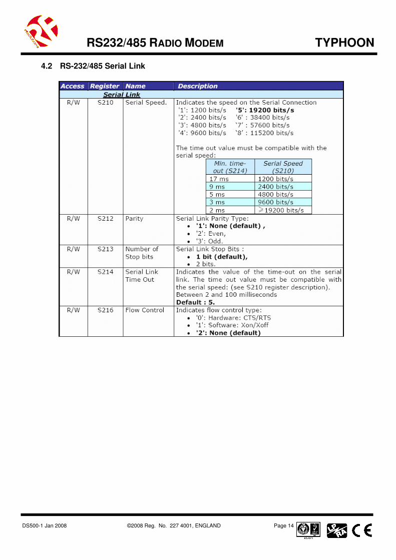
4.2 RS-232/485 Serial Link

DS500-1 Jan 2008 ©2008 Reg. No. 227 4001, ENGLAND Page 15
TYPHOON RS232/485 RADIO MODEM
4.3 Operation and Power Settings
LBT = Listen Before Talk
4.4 Network Control

DS500-1 Jan 2008 ©2008 Reg. No. 227 4001, ENGLAND Page 16
TYPHOON RS232/485 RADIO MODEM
4.5 Radio Test Commands
These AT commands are provided to enable measurements during continuous transmission to be taken and are primarily used during radio tests (radiated power, bandwidth, etc.) to show conformance to the ETS 300 220 standard. A test that is in progress will terminate if the modem receives a character from the host (i.e. any character is typed on the host’s keyboard):
• ATT0 <CR>: Transmit pure carrier at centre frequency
• ATT1 <CR>: Transmit pure carrier representing ‘1’
• ATT2 <CR>: Transmit pure carrier representing ‘0’
• ATT3 <CR>: Transmit modulated carrier at maximum
• ATT6 <CR>: Transmit modulated carrier at minimum Notes
• After entering an AT command (ended by <CR>), the modem acknowledges it by returning a code which is either "OK", or "ERROR"
• Entering the "+++" command returns OK
• The commands are effective after a maximum delay of 10 ms. A new command can be entered after the current command has been acknowledged by the modem
5 Ordering Information
Part Number Description
TYPHOON-800 RF modem, 800 Metre, RS232/485, IP68 enclosure
TYPHOON-4000 RF modem, 4000 Metre, RS232/485, IP68 enclosure
PSU-12V1AIN-IP Power supply, 240Vac/12Vdc/1A, wall mount, 3-pin IEC mains plug
For more information or general enquiries, please contact R. F. Solutions Ltd.,
Unit 21, Cliffe Industrial Estate, South Street, Lewes,
E Sussex, BN8 6JL. England
Tel +44 (0)1273 898 000 Fax +44 (0)1273 480 661
Email [email protected] http://www.rfsolutions.co.uk