rs232 port protocol and syntax - cvpusa.com port protocol and syntax easydcc computer port rs232...
TRANSCRIPT

1
RS232 Port Protocol and Syntax EasyDCC Computer Port RS232 PROTOCOL - Version 6 ©2001-20014 by CVP Products
Updated July 2014
Errata Location And Copyright Information
All corrections will be posted on the CVP website: http://www.cvpusa.com. Any reference to this work must include the copyright statement. Copies may not be made, distributed or sold without written permission.
Command Station Software Version And A Note About Programming Skills
Requires Command Station software version 629 or higher. This information is written with the assumption you are familiar with computer communications. It is not written for novice programmers. The Basic Language program fragments are given for illustrative purposes only. Most initial communication problems are due to faulty cabling between EasyDCC and your computer. Look there if you seem to be unable to establish communications.
Interface Cable And Adapters
The Command Station uses three connectors of a 6-pin RJ11 (6p6c) telephone-type plug. The Command Station jack has the following pin assignments: Pin 1 = TXOUT, Pin 2 = Ground, Pin 5 = Ground, Pin 6 = RXIN. If you don't want to build your own, then use an adapter.
Communications Uses a baud rate of 9600. Each byte is 8-bits, no parity, and one stop bit. Only ASCII characters are sent.
3rd Party Software
As of the date on this document, there is one well known program that uses the computer port. If you have any questions, contact them directly since CVP does not offer technical support for the Computer port. for further information. It is the responsibility of the 3rd party to support their own software including updates to support EasyDCC's new features. If you are having problems with their software and EasyDCC, please contact them directly.
DecoderPRO
http://jmri.sourceforge.net/apps/DecoderPro/
Can't Communicate? If you can not communicate with the Command Station, and your computer's serial settings appear correct, try reversing your cable's the Receive and Transmit pins. The definition of these two pins is somewhat ambiguous and reversal of the pins may
solve the problem.
Command Serial
Station Cable
Enable Port’s Q-D-S Commands These 3 commands allow a computer to operate any locomotive and are also used with some decoder programming software. The factory default for these commands is disabled.
To activate the Q-D-S commands, key in SETUP 0. To deactivate, use the same keystrokes. Once enabled, the system will remember the status. See page 35 for
the messages that appear upon power up.
USB to Serial Adapters
If your PC doesn't have a serial port, you must use a USB to Serial Port adapter. We have tested and verified the proper operation of the KEYSPAN adapter, part number USA-19HS. It has a USB connector on one end and a DB9 male connector on the other.
Although we can't claim to have tested every machine, it has worked flawlessly with several different machines that used Windows XP.
The KEYSPAN adapter was used to test the new Command Station Software and has been verified
as working properly.

2
Enable RS232 Q-D-S Commands Before using the computer port, you must enable the full set of RS232 commands. This is a manual operation, done with a couple of keystrokes. This command toggles between enabled and disabled. If enabled, the SETUP/ASSIGN Q-D-S Enabled message will appear and you must press ESC to return to the normal screen. If it is active, pressing SETUP 0 will disable the feature and the normal screen will appear. This setting is retained with power off.
� SETUP
� 0 Enables the 3 commands in the RS232 section
� ESC to return to the normal screen
To disable the port, use the same keystroke sequence. The port is also disabled if the Command Station memory is cleared. To tell you that that system has the RS232 port enabled, a new message appears when power is turned on. The revised initiation message stream is shown on page Error! Bookmark not defined.
Commands and Command Structure Hexadecimal Values
The small h following a value defines the value as a hex value. For example, 60Fh means the value is 60F hex. Decimal notation does not have any suffix.
Commands
All received commands must use the ASCII character set (upper case) and be terminated by a Carriage Return (Enter). The command sequences must use the exact number of characters shown, for the command to be executed.
The format below shows the data and the number of characters required. Spaces are shown as delimiters in the command sequences below. The spaces are ignored by the command station and may be used or not used by the User as he desires.
If the command executes, properly or otherwise, various responses will be transmitted and are described at each command description. If the command received was invalid or, for whatever reason, could not be decoded, a response of ?<CR> will be transmitted. This response also indicates that the system is now ready for another command.
SEND Command is primarily for function commands. It allows the sending of a command for a specified number of cycles before being automatically discarded.
QUEUE Command is primarily for speed commands. Once placed in queue, the command is repeated, until removed or overwritten by a new command.
Command Modes
At power-up/reset, the command station will default to the Operation mode. (There are 2 modes: Operation and Programming). In the Operation mode the command station will respond only to Operation Commands; in the Programming mode it will respond only to Programming Commands.
Command Transmission Hierarchy
This is the sequence used by the Command Station to handle inputs from various devices connected to the available ports. All four of these command sources are independent and each could contain a command for the same locomotive which may be confusing (and amusing to watch) as the decoder receives conflicting commands.
Top Priority: Sends commands to the track as dictated by the commands from the handheld throttles (plug-in or wireless).
#2 Priority: Sends commands to the track as dictated by the responses from Throttle A and Throttle B.
#3 Priority: Sends commands to the track as dictated by the contents of the Main Queue. The Q (Queue) RS232-command adds packets to the Main Queue, where they remain until they are removed from the Main Queue by the D (DeQueue) RS232-command.
#4 Priority: Sends commands to the track as dictated by the contents of the Temp Queue. The S (Send packet) RS232-command adds packets to the Temp Queue with a Count specified. The command specified by the packet in the Temp Queue is sent to the track the number of times specified by the Count value, then it is automatically removed from the Temp Queue.
Operation Commands
Setup/Assign
Setup/Assign Q-D-S Enabled

3
As most EasyDCC users know, trying to operate a locomotive who's address has been entered into both a Command Station throttle and a handheld throttle causes problems. The same problems arise when trying to operate a locomotive over the RS-232 interface when its address has also been assigned to a Command Station/handheld throttle (or vice-versa). Be sure to de-assign any Command Station Throttle or handheld throttle before sending commands to the specified locomotive address. Current assignments can be found in data table TABLE1 described in the programming notes section starting on page 13.
Display Memory Format: F y xxxx where y=hex number of 16-byte lines (0 implies 16), and xxxx=hex RAM memory address. Example: F 2 0C00 Display 2 16-byte lines of memory starting at location 0C00h (3072 decimal). The information transmitted is 32 ASCII bytes per line requested, e.g. '01 02 03 04 05 06 07 08 09 0A 0B 0C 0D 0E 0F', followed by a terminating <CR>, and followed by O<CR>...to indicate system is ready for next command. ("O" indicating ready for next Operation Command).
Kill Main Track
Format: K No data required. Causes all clocks to Main Track to stop. The Program Track clocks will continue but the Program Track will not be enabled unless Program Mode is selected. Successful completion of this command will be indicated by transmitting O<CR> to indicate the system is ready for the next command.
Enable Main Track Format: E No data required. Causes the Main Track clocks to be resumed. Successful completion of this command will be indicated by transmitting O<CR> to indicate the system is ready for the next command.
Display Version Number Format: V No data required. Causes the version number of the Command Station software and the release date to be sent to the PC. The information transmitted is 12 ASCII bytes, beginning with a V,containing the information requested (e.g. 'V238 06 02 1997')...for version number 238 , followed by a terminating <CR>, followed by O<CR>...to indicate system is ready for next command.
Queue Packet (see comment regarding “QUEUE” commands on page 2) Format: Q xx xx ... xx Where xx is the hex value of each byte of the packet to be placed in the main command queue (up to 6 bytes may be specified, and must include the checksum byte). Once in the main command queue, the packet will be sent each cycle until it is removed by a Dequeue command or replaced by another packet to the same decoder number. Each cycle will consist of sending to the main track each packet that resulted from information polled from a physical throttle (local and handheld), then sending each packet that has been placed in the main command queue, then sending each packet that has been placed in the temporary command queue (see description of temporary command queue at Send Packet command description). When a decoder number is the same in a packet being received and in a packet already in the queue, the newest packet will replace the existing one. Two packets addressing the same decoder cannot be in the main command queue. Packets may contain decoder numbers up to 10239 (hex 27FF). The maximum number of packets that may be placed in either queue is 32. (Operational note: If 32 3-byte packets are placed in a queue, that

4
represents a time delay of approximately 1/4 second that is added between packets to any one decoder on the main track.) Example: Q 17 67 70 Put a command for loco address 23 for speed 6, forward direction, in the main queue. Q C6 0C 67 AD Put a command for loco address 1548 (hex 60C) for speed 6, forward direction, in the main queue. Successful completion of placing the packet in the queue will be indicated by transmitting O<CR> to indicate the system is ready for the next command. If the packet will cause the queue limit to be exceeded the packet will not be placed in the queue. This will be indicated by transmitting R<CR> . ("R" indicating the command was decoded but Refused). The system will then be ready for another command.
See the section on DATA FORMATS for a description of the basic packet formats.
Dequeue Packet Format: D xx xx Where xx xx is the hex address of the loco (decoder) whose packet is to be removed from the main command queue. The first byte of the address must be 00 to indicate 'short' address. The two msb's of the first byte must be 1's to indicate 'long' address. See Example. Example: D C6 0C Remove command for loco #1548 (60Ch) from main queue. D 00 17 Remove command for loco #23 (17h), short address, from main queue. D C0 17 Remove command for loco #23 (17h), long address, from main queue.
Successful completion of removing the packet from the queue will be indicated by transmitting O<CR> to indicate the system is ready for the next command. If the decoder number specified is in the queue more than one time, all entries will be removed. If the decoder number cannot be found in the queue, no action will be taken but the system will not reject the command and will indicate successful completion.
Send Packet (see comment regarding “SEND” commands on page 2) Format: S yy xx ...xx Where yy=the hex value of the number of times to send the packet to the main track, and xx is the hex value of each byte of the packet to be placed in a temporary send queue (up to 6 bytes may be specified, and must include the checksum byte). Once the packet has been sent the number of specified times, it will be removed from the temporary send queue. Multiple packets for the same decoder may be place in the temporary queue. Packets may contain decoder numbers up to 10239 (hex 27FF). The maximum number of packets that may be placed in the queue is 32. See Operational note at Queue Packet command description. Example: S 01 22 85 A7 Put the command for loco address 34 to turn on functions 1 and 3 in the temporary send queue. After it is sent 1 time, remove it from the queue. Successful completion of placing the packet in the queue will be indicated by transmitting O<CR> to indicate the system is ready for the next command. If the packet will cause the queue limit to be exceeded the packet will not be placed in the queue. This will be indicated by transmitting R<CR> . The system will then be ready for another command. See the section on DATA FORMATS for a description of the basic packet formats. ‘h’ when used with a number, defines this value as a hexadecimal value. For example, the number 270Fh means the value 270F is a hex number and must not be confused with a decimal number.
Read Loco Information Format: L xxxx Where xxxx is the hex address (cannot exceed decimal 9999 or 270Fh) of the loco whose speed, direction, number of speed steps, and function states are to be transmitted to the PC.

5
Example: L 1222 Requests speed, direction, speed steps, functions for decimal loco #4642. The information transmitted is 11 ASCII bytes, beginning with an L,containing the information requested, with the following format: Lxxxx ss yy zz where xxxx echoes the loco hex address ss = the speed/direction value (bit7 = direction; 1:forward, 0:reverse) (bits 6-0 = speed value...1 through 126) yy = the speed-step/function 0-4 value (bit7: 1 = 128 speed steps) (bit6: 1 = 28 speed steps) (bit5: 1 = loco address is registered but no throttle is assigned (bit4: 1 = Function 0 on) (bit3: 1 = Function 4 on) (bit2: 1 = Function 3 on) (bit1: 1 = Function 2 on) (bit0: 1 = Function 1 on) zz = the function 5-12 value (bit7: 1 = Function 12 on)
(bit6: 1 = Function 11 on) (bit5: 1 = Function 10 on) (bit4: 1 = Function 9 on) (bit3: 1 = Function 8 on)
(bit2: 1 = Function 7 on) (bit1: 1 = Function 6 on) (bit0: 1 = Function 5 on) followed by a terminating <CR>, followed by O<CR>...to indicate system is ready for next command. If loco xxxx is not in the system, i.e. not registered, the returned values for ss, yy, and zz values will be all zero. Example: L 1222 85 05 01...to indicate Loco #4642 (1222h): has a speed/direction value of hex 85 (indicating forward at 5/126 of full speed), a speed-step/function 0-4 value of 05 (indicating 14-speed-steps and functions 1 and 3 on), and a function 5-12 value of 01 (indicating function 5 is on).
Set Loco Characteristics Format: C xxxx yy zz Where xxxx is the hex address of the loco (cannot exceed decimal 9999 or 270Fh) to be set and yy = speed-steps/function 0-4 value and zz = function 5-12 value Upon receiving this command, the command station will setup its internal tables and send programming packets to the decoder address xxxx, setting the decoder's speed step value in CV#29 according to the yy value. If the loco addresses are not present, or the locomotive is not capable of main track programming (“OPS” mode programming) then this command can not program the decoder address and will not function properly.
Example: C 1222 05 01 Setup the speed-step/function 0-4 value and the function 5-12 value of Loco #4642 to 05 and 01 respectively and send programming packets to loco #4642 to set its CV#29 to specify the requested number of speed-steps. The bits not related to functions and speed are not written to by this command. Those bits do not change value. Successful completion of setting the loco characteristics will be indicated by transmitting O<CR> to indicate the system is ready for the next command. If the loco address has not previously been registered, this command will register it. See the description at Read Loco Information for a description of the speed-step/function 0-4 value, and the function 5-12 value.

6
Add Loco(s) to a Consist ... Normal Direction Format: GN yy xxxx...xxxx Add up to 8 loco addresses with a hex value of xxxx (cannot exceed decimal value 9999 or 270Fh) to
the consist whose hex number is yy (cannot exceed decimal value 255 or FFh; the loco addresses to be added run in the Normal direction. The consist number specifies a standard consist.
Example: GN 01 1222 1400 0515 Adds loco 4642, 5120, and 1301 to consist 1 (a standard consist) to run in Normal direction. If the number of loco addresses specified contain more than 8 addresses, or addresses exceed the consist’s capacity (capacity is 8 addresses), those addresses after the first 8 will be ignored. No error message will be returned to notify of the overage.
If the consist number yy already exists as an advanced consist, the command will be ignored. No error message will be returned to indicate the error.
Successful completion of adding the loco(s) to the consist will be indicated by transmitting O<CR> to indicate the system is ready for the next command.
This command performs the same operation as keystrokes, Setup, Consist, nn ADD xxxx, Normal at the Command Station keyboard. Note that for these commands the consist number must be within the 1-255 range. See note at the bottom of this page.
Add Loco(s) to a Consist ... Reverse Direction
Format: GR yy xxxx...xxxx Add up to 8 loco addresses with a hex value of xxxx (cannot exceed decimal value 9999 or 270Fh) to
the consist whose hex number is yy (cannot exceed decimal value 255 or FFh); the loco addresses to be added run in the Reverse direction. The consist number specifies a standard consist. Example: GR 01 1222 1400 0515
Adds loco 4642, 5120, and 1301 to consist 1 (a standard consist) to run in Reverse direction.
If the number of loco addresses specified contain more than 8 addresses, or addresses exceed the consist’s capacity (capacity is 8 addresses), those addresses after the first 8 will be ignored. No error message will be returned to notify of the overage.
If the number of loco addresses specified contain more than 8 addresses, or addresses exceed the consist’s capacity (capacity is 8 addresses or less), those addresses after the first 8 will be ignored. No error message will be returned to notify of the overage.
If the consist number yy already exists as an advanced consist, the command will be ignored. No error message will be returned to indicate the error.
Successful completion of adding the loco(s) to the consist will be indicated by transmitting O<CR> to indicate the system is ready for the next command.
This command performs the same operation as keystrokes, Setup, Consist, nn ADD xxxx, Reverse at the Command Station keyboard, except nn must be between 1-255.
Standard Consist Number Range Is Restricted For RS232 Port Commands When working with standard consists from the RS232 port, there is a strict limit on the consist number range. A standard consist number must be within the range of 1 to 255. Do not try to create a standard consist number by using 4-digit loco address. It will not be accepted by the Command Station. This limitation applies only to consists created or edited from the RS323 port. The limit does not apply to consists created via the Command Station keyboard. Standard
consists created by the keyboard can only be edited via the RS232 port if they are within the number range of 1-255.
For Best System Performance Use Advanced Consists Only The best system performance and the most flexible function key assignments are available for advanced consists only.

7
Subtract Loco(s) from a Consist Format: GS yy xxxx....xxxx Remove up to 8 loco numbers with a hex value of xxxx (cannot exceed decimal value 9999 or 270Fh)
from the consist) whose hex number is yy (can not exceed decimal value 255 or FFh. The consist number specifies a standard consist.
Example: GS 01 1222 1400 0515
Removes loco 4642, 5120 and 1301 from consist 1 (as a standard consist).
Successful completion of removing the loco(s) from the consist will be indicated by transmitting O<CR> to indicate the system is ready for the next command. If this command attempts to remove a loco number that is not presently in the specified consist, or attempts to remove a loco from an advanced consist, or a non-existent consist, the system will accept the command and will indicate successful completion. No indication will be sent that the consist number was not accepted
This command performs the same operation as keystrokes, Setup, Consist, nn REMOVE xxxx, Reverse at the Command Station keyboard, except nn must be between 1-255.
Kill Consist Format: GK yy Remove all loco addresses from the consist whose hex number is yy (cannot exceed decimal value 255 or FFh.)
The consist number specifies a standard consist. Example: GK 01 Remove all loco addresses from consist 1 (as a standard consist) Successful completion of removing all loco addresses from the consist will be indicated by transmitting O<CR> to indicate the system is ready for the next command. Note: If the specified consist number does not exist, or the specified number is an advanced consist, or a non-existent consist, (but the specified consist number is legal), the system will accept the command and will indicate successful completion. No indication will be sent that the consist number was not accepted. This command performs the same operation as keystrokes, Setup, Consist, nn ADD xxxx, Reverse at the Command Station keyboard, except nn must be between 1-255.
Standard Consist Number Range Is Restricted For RS232 Port Commands When working with standard consists from the RS232 port, there is a strict limit on the consist number range. A standard consist number must be within the range of 1 to 255. Do not try to create a standard consist number by using 4-digit loco address. It will not be accepted by the Command Station. This limitation applies only to consists created or edited from the RS323 port. The limit does not apply to consists created via the Command Station keyboard. Standard
consists created by the keyboard can only be edited via the RS232 port if they are within the number range of 1-255.

8
Display Consist
Format: GD yy Display the contents of the consist whose hex number is yy (yy implies a standard consist and the value cannot
exceed decimal value 255 or FFh). Example: GD 01 Display all loco addresses from consist #1, which is a standard consist The information transmitted is at least 7 bytes beginning with the character 'G' and containing the consist number and the number of each loco in that consist (e.g. G02 050F 0736 194A <CR>). If the requested consist does not exist as a standard consist, the information transmitted will be Gyy 0000 <CR>.
Direction Orientation In A Consist
If a loco address in the consist, is in the reverse direction, the most significant bit of the returned 2-byte number will be a 1. For example, if address 050Fh is in the consist in the reverse direction, its address will be returned as 850Fh. After transmitting the requested information, O<CR> will be transmitted to indicate the system is ready for the next command.
Programming Mode Format: M No data required. Causes the main track to be halted (by stopping the Main Track clocks) and prevents any further packet activity on the Main Track. Any keyboard/display sequence in process will be terminated (as if ESC had been pressed); the display will indicate RS232 programming mode by displaying "Controlled by Computer". No keyboard or pushbutton on the command station will be acknowledged (except the Reset), and no throttle will be polled. These conditions will remain until leaving the Programming mode. Successful completion of this command will be indicated by transmitting P<CR> to indicate the system is ready for the next command where “P” indicates it is ready for the next programming command.
Until the Programming mode has been exited, only Programming commands will be accepted.
PROGRAMMING COMMANDS
Read CV
Format: R xxx Where xxx=hex number of CV to be read. Example: R 01D Read and display the value in the decoders Configuration Variable #29. The format of the data transmitted to the PC/terminal will be: CV xxx yy ,where xxx is the CV number echoed, and yy is the hex value read from the CV. (If the CV cannot be read, the value will be transmitted as "--") followed by a terminating <CR>, followed by P<CR>...to indicate system is ready for next command.

9
Dump 10 CVs
Format: D xxx Where xxx=hex number of the starting CV to be read. Example: D 041 Read and display the values in the decoders Configuration Variables #65 through #74. The format of the data transmitted to the PC/terminal will be: CV xxx yy ,where yy is the hex value read from CV.number xxx (and repeated for the next 9 sequential CV numbers) (If any CV cannot be read, its value will be transmitted as "---") followed by a terminating <CR>, followed by P<CR>...to indicate system is ready for next command.
Program CV
Format: P xxx yy Where xxx=hex number of CV to be programmed and yy is the hex value of the value to be programmed. Example: P 003 014 Program CV#3 of the decoder with a value of decimal 20.
Successful completion of this command will be indicated by transmitting P<CR> to indicate the system is ready for the next command.
Read Register
Format: V x Where x=register number (1 through 8).
See the section on DATA FORMATS for the meaning of the contents of the registers and a description of the relationships between register numbers and CV numbers for those decoders referred to as Type 1 and Type 2.
Example: V 2 Read and display the value in register 2. The format of the data transmitted to the PC/terminal will be: V x yy Where yy is the hex value read from the register x. (If the register cannot be read, the value will be transmitted as "---") followed by a terminating <CR>, followed by P<CR>...to indicate system is ready for next command.
Write Register
Format: S y xx Where y=register number (1 through 8) and xx=hex value to be written. See the section on DATA FORMATS for the meaning of the contents of the registers and a description of the relationships between register numbers and CV numbers for those decoders referred to as Type 1 and Type 2. Example: S 1 003 Program register 1 of the decoder with the value of 3. Successful completion of this command will be indicated by transmitting P<CR> to indicate the system is ready for the next command.

10
Exit Programming Mode Format: X No data required. Causes the main track to resume normal operation. The command station display will indicate Status OK, throttle polling will resume, the keyboard and front panel pushbuttons will be enabled, and packets will again be sent to the main track. Successful completion of this command will be indicated by transmitting O<CR> to indicate the system is ready for the next command.<"O" indicating ready for next Operation Command> Once the Programming mode has been exited, only Operation commands will be accepted.
DATA FORMATS
Basic Packet Format – Main Track Programming (Ops Mode Programming) Generally, each packet consists of : address, instruction, checksum. See the DCC-RPs for more details on packet construction. Examples shown below include checksum (XOR bitwise) Binary: 0aaaaaaa 00000000 Reset decoder a:a Example (hex) : 17 00 17 Reset decoder 23 (hex 17) Binary: 0aaaaaaa 00000001 Hard Reset decoder a:a (set to defaults) Example (hex) : 17 01 16 Hard Reset decoder 23 (hex 17) Binary: 0aaaaaaa 00010010 0xxxxxxx Set consist address of decoder a:a to x:x (dir=norm) Example (hex) : 17 12 05 00 Set decoder 23's consist address to 05 (dir=norm) Binary: 0aaaaaaa 00010011 0xxxxxxx Set consist address of decoder a:a to x:x (dir=reverse) Example (hex) : 27 13 11 25 Set decoder 39's consist address to 17 (dir=reverse) Binary: 0aaaaaaa 00111111 0sssssss Send speed s:s, reverse direction, to decoder a:a Example (hex) : 17 3F 1F 37 Send decoder 23 a speed of 31 (of 126), reverse direction. (A speed value of 0 = stop; 01 = emergency stop) Binary: 0aaaaaaa 00111111 1sssssss Send speed s:s, forward direction, to decoder a:a Example (hex) : 17 3F 9F B7 Send decoder 23 a speed of 31 (of 126), forward direction. (A speed value of 0 = stop; 01 = emergency stop) If decoder has been setup to accept 14 speed-steps Binary: 0aaaaaaa 010xdddd Send speed d:d, reverse direction, to decoder a:a, with x = F0 state. Example (hex) : 21 48 66 Send decoder 33 a speed of 7 (of 14), reverse direction, with F0 off. (A speed value of 0 = stop; 01 = emergency stop) If decoder has been setup to accept 14 speed-steps Binary: 0aaaaaaa 011xdddd Send speed d:d, forward direction, to decoder a:a, with x = F0 state. Example (hex) : 21 76 57 Send decoder 33 a speed of 6 (of 14), forward direction, with F0 on. (A speed value of 0 = stop; 01 = emergency stop)

11
If decoder has been setup to accept 28 speed-steps Binary: 0aaaaaaa 010ddddd Send speed d:d, reverse direction, to decoder a:a Example (hex) : 21 47 66 Send decoder 33 a speed of 7 (of 28), reverse direction. Speed values to 28-speed-step decoders have the following
meanings (values are shown in hex): 00 = stop 01 = emergency stop 11 = emergency stop 02 = 1st speed step 12 = 2nd speed step 03 = 3rd speed step 13 = 4th speed step, etc If decoder has been setup to accept 28 speed-steps Binary: 0aaaaaaa 011ddddd Send speed d:d, forward direction, to decoder a:a Example (hex) : 21 67 66 Send decoder 33 a speed of 7 (of 28), forward direction. Speed values to 28-speed-step decoders have the following meanings (values are shown in hex): 00 = stop 01 = emergency stop 11 = emergency stop 02 = 1st speed step 12 = 2nd speed step 03 = 3rd speed step 13 = 4th speed step, etc Binary: 0aaaaaaa 100ddddd Send 5 auxiliary functions (0,4,3,2,1) to decoder a:a (1=on) Example (hex) : 33 91 A2 Send decoder 51 a command to turn F0 and F1 on, and F2 F3 and F4 off. (If decoder is setup for 14 speed steps, F0 is controlled by speed packet) Binary: 0aaaaaaa 1011dddd Send 4 auxiliary functions (8,7,6,5) to decoder a:a (1=on) Example (hex) : 1A B8 A2 Send decoder 26 a command to turn F8 on, and F5,F6 and F7 off. Binary: 0aaaaaaa 1010dddd Send 4 auxiliary functions (12,11,10,9) to decoder a:a (1=on) Example (hex) : 1A B8 A2 Send decoder 26 a command to turn F12 on, and F9,F10 and F11 off. Binary: 0aaaaaaa 11110010 dddddddd Send decoder a:a an acceleration adjustment value of d:d (for CV #23) Example 10 F2 0B E9 Send decoder 16 an acceleration adjustment value of +11. Negative adjustment values are permitted - See RP 9.2.2 Binary: 0aaaaaaa 11110011 dddddddd Send decoder a:a a deceleration adjustment value of d:d (for CV #24) Example 10 F3 10 F3 Send decoder 16 a deceleration adjustment value of +16. Negative adjustment values are permitted - See RP 9.2.2 Binary: 0aaaaaaa 111010cc cccccccc 11110bbb Command decoder a:a to write a zero in bit b:b of CV# c:c. (-1) Example 12 E8 1C F2 14 Command decoder 18 to write a zero in bit 2 of CV# 29. (CV writes require 2 identical back-to-back packets)
Note that the field specifying the CV# contains the CV number minus 1, i.e. 1Ch = CV#29
Binary: 0aaaaaaa 111010cc cccccccc 11111bbb Command decoder a:a to write a one in bit b:b of CV c:c. (-1) Example 12 E8 1C FA 1C Command decoder 18 to write a zero in bit 2 of CV 29. (CV writes require 2 identical back-to-back packets)

12
Binary: 0aaaaaaa 111011cc cccccccc dddddddd Command decoder a:a to write the value d:d in CV c:c. (-1) Example 13 EC 03 64 98 Command decoder 19 to write 100 in CV 04. (CV writes require 2 identical back-to-back packets) Binary: 10aaaaaa 1aaa0ddd De-activate output d:d of Accessory decoder a:a (aaa in second byte are complemented MSBs of address) Example 93 F3 60 De-activate output 3 of Accessory decoder 19 Binary: 10aaaaaa 1aaa1ddd Activate output d:d of Accessory decoder a:a (aaa in second byte are complemented MSBs of address) This command is used to set the decoder to either reverse or normal as shown in the example below: Example 83 F9 7A Activate decoder card #5, output A, reverse Example 83 F8 78 Activate decoder card #5, output A, normal
Long Addresses
If a decoder has been setup to accept 14-bit addresses (long addresses) replace the first byte (0aaaaaaa) of each of the above decoder packets with two bytes formatted thus (11aaaaaa aaaaaaaa ). The value of this 14-bitaddress field cannot exceed 10239 (27FF hex). If the decoder has extended addressing enabled (14-bit address) the decoder's address is sent in the first 2 bytes. The format of the 2 bytes is: 11aaaaaa aaaaaaaa. Format for 14-bit address : Binary: 11aaaaaa aaaaaaaa 00111111 0sssssss Example: To send loco address 1023 a reverse speed of 31 is: C3 FF 3F 1F 1C
Decoder Registers and Configuration Variables
Type 3 Decoders (Direct Mode Addressing Capable)
Those decoders whose programmable Configuration Variables may be accessed directly (Direct Mode) are referred to as Type 3 decoders in EasyDCC documents. A definition of the CVs is provided in the NMRA DCC Recommended Practices 9.2.2.
Type 2 Decoders (Page Mode Addressing)
Those decoders whose programmable CVs are accessed indirectly through Paged Addressing are referred to as Type 2 decoders in EasyDCC documents. These decoders have 6 accessible registers with the following meanings: Register 1 = Data Register 0 Register 2 = Data Register 1 Register 3 = Data Register 2 Register 4 = Data Register 3 Register 5 = Basic Configuration Register (see description of CV#29 in NMRA document) Register 6 = Page Register The 'page' consists of Data Registers 0 through 3; the Page Register is the 'pointer' into CV memory. If the Page Register contains 1, Data Registers 0 through 3 represent CV#s 0 through 3. If the Page Register contains 2, Data Registers 0 through 3 represent CV#s 4 through 7. If the Page Register contains 3, Data Registers 0 through 3 represent CV#s 8 through 11, etc.
Type 1 Decoders – (Register mode addressing) Mobile
Those decoders whose programmable CVs consist entirely of 8 accessible registers (Physical Register Addressing) are referred to as Type 1 decoders in EasyDCC documents. These 8 registers have the following meanings: Register 1 = Decoder address (see description of CV#1 in NMRA document) Register 2 = Start voltage (see description of CV#2 in NMRA document) Register 3 = Acceleration (see description of CV#3 in NMRA document) Register 4 = Deceleration (see description of CV#4 in NMRA document) Register 5 = Basic Configuration Register (see description of CV#29 in NMRA document) Register 6 = Reserved for Page Register Register 7 = Version Number (see description of CV#7 in NMRA document)
This command is not understood by most accessory decoders,
including the AD4.

13
Register 8 = Manufacturer ID Number (see description of CV#8 in NMRA document)
Type 1 Decoders – (Register mode Addressing) Accessory
Those Accessory decoders whose programmable CVs consist entirely of 8 accessible registers (Physical Register Addressing), also referred to as Type 1 decoders in EasyDCC documents, have slighty different register meanings: Register 1 = Decoder lower address (see description of CV#512 in NMRA document) Register 2 = Decoder upper address (see description of CV#512 in NMRA document) Register 3 = undefined Register 4 = undefined Register 5 = Configuration Register (see description of CV#540 in NMRA document) Register 6 = Reserved for Page Register Register 7 = Version Number (see description of CV#7 in NMRA document) Register 8 = Manufacturer ID Number (see description of CV#520 in NMRA document)
Programming Notes This information is provided for advanced programmers only. No technical support is provided for development of PC based programs.
Modifying Standard Consists
This information should be kept in mind when developing programs that add (or delete) loco addresses to (or from) a standard consist. This includes RS232 commands GN....., GR..... & GS......
1. If the command is sent to add a loco address to a consist, and that loco address is already in the consist, the command will simply be ignored.
2. If the command is sent to remove a loco address from a consist, and that loco address is not in the consist, the command will simply be ignored.
3. If the command is sent to add a loco address to a consist, and there is no room for the loco address to be added, the command will simply be ignored.
4. If the command is sent to remove a loco address from a consist, and that consist does not exist, the command will simply be ignored.
5. If a command is sent to add a loco address to a Standard consist, and that loco address is already in an Advanced consist, no action will be taken and the command will be ignored.
6. If a command is sent to add a loco address to an Advanced consist, and that loco address is already in an Advanced consist, the loco address will be REMOVED from its previous consist and added to the consist specified.
7. If a command is sent to add a loco address to a Standard consist, and that loco address is already in a Standard consist, the loco address will remain in its previous consist AND be added to the consist specified.
8. When messages arrive at the Command Station’s RS232 port, the command station checks that the incoming message format is correct and that there is room in the queue for it. The Command Station does not check the validity of the contents.

14
Locations For Data Tables In Command Station RAM Updated 12/15/2006 ©2002-2006 by CVP Products
LORAM EQU 00020H ;LOW RAM (FOR CHECKING MEMORY)
....4 byte pattern here (BB BA BE BB) verifies that RAM battery is 'good'.
DECODRAM EQU 00032H ;STORAGE FOR DECODER TYPE
....1 byte containing 1,2 or 3 to indicate default decoder type
CHAREA EQU 00100H ;Command sequence from PC
....Last character string received from PC, including CR
SPTAB EQU 00700H ;Speed table (33 values)
....Index by throttle ID# (Ignore ID #0)
....Last speed value for each throttle ID# (throttle may no onger be active but this
was the last value it sent).
80H = stop,
81H-FEH = 1-126 clicks forward
7FH-02H = 1-126 clicks reverse
(Throttle A has throttle ID# 33H)
(Throttle B has throttle ID# 32H)
CHTAB EQU 00800H ;Loco characteristic Table (speed steps,
F(x)) (255 values)
....Index by TABLE2 pointer
e.g. Address 0801H = data for loco address at TABLE2 , address 2301H
....ignore address 0800H]
....Characteristics/function state of each loco
bit7 1=128 speed steps
bit6 1=28 speed steps
bit5
bit4 F(0) 1=lamps on, 0=lamps off
bit3 F(4)
bit2 F(3)
bit1 F(2)
bit0 F(1)
F3TAB EQU 00A00H ;Fcns F12-F5 (255 values...ignore A00H)
F2TAB EQU 00B00H ;Loco descriptors (255 values)
....Index by TABLE2 pointer
[e.g. Address 0B01H = data for loco address at TABLE2; ignore address 0B00H]
bit7 1=this loco address declared inactive (candidate for purging)
bit6 1=this loco address may be declared inactive in 16 hours
bit5 1=this loco address is in a standard consist
bit4 1=this loco address is in an advanced consist
Loco numbers may be declared inactive if not accessed for 16 hours (of power on time).
An inactive number is not purged from the system unless a TABLE2 overflow would result
from registering a new number.
NRTAB1 EQU 00C00H ;(31 values)Timer for responding throttles. Refreshes
functions F0-F4 when throttle quits responding.
NRTAB2 EQU 00E00H ;(31 values)Timer for responding throttles.
Flags system to refresh track when throttle quits responding.
CABTAB EQU 00D00H ;Keep tabs on throttles (31 values)
....Index by throttle ID# (Ignore ID #0)
Shows which throttles have answered when polled.
If entry=0, throttle has not answered in approximately 2 minutes and
is declared inactive.

15
When the throttle answers a poll, a value of 255 is entered and the value is
decremented every second that the throttle fails to answer.
NRTAB2 EQU 00C00H ;Timer for active, but non-responding, throttles.
A value of 80 is entered whenever a throttle responds. The value is decremented
every non-response of the throttle. When a value of zero is reached, a track
refresh is initiated.
SPEEDTAB EQU 00F00H ;8 speed tables (256)
....Storage for 8 groups of 28 values each for writing to CVs
67-94.
MAINQ EQU 01000H ;Main Queue (256)
....Main Queue where packet information for 32 packets (8 bytes
of info per packet).
Byte 1: bit3=0, this packet slot is available.
bit3=1, this packet slot is filled,
bits 2-0 = # of pkt bytes.
Byte 2: reserved
Byte 3-8: 1st through 6th packet byte (3 min, 6 max)
TEMPQ EQU 01100H ;Temporary Queue (256)
....Temporary Queue where packet information for 32 packets
(8 bytes of info per packet).
Byte 1: bit3=0, this packet slot is available.
bit3=1, this packet slot is filled,
bits 2-0 = # of pkt bytes.
Byte 2: Number of times to send packet.
Byte 3-8: 1st through 6th packet byte (3 min, 6 max)
GANGTAB EQU 01200H ;Route numbers [64X64bytes]
....Index by accy route#; 64 routes, each route has 32 2-byte output
address block (Ignore route #0...Only route numbers 1-63 allowed)
Each of the 32 output addresses has the following format:
Byte 1: bit7=0, for this route, switch (at output address) is Normal
bit7=1, for this route, switch (at output address) is Reverse
bit3-0, MSB of the output address.
Byte 2: 8 LSBs of the output address.
TABLE1 EQU 02200H ;Throttle IDs vs loco#s assigned (33x2)
....Index by throttle ID# x 2...2 bytes per entry (Ignore ID #0).
Shows 4-digit loco/consist address assigned to each throttle ID#
(Throttle A has throttle ID# 33)
(Throttle B has throttle ID# 32)
TABLE2 EQU 02300H ;Active loco (consist) MSbytes (255 entries)
...1 byte per entry (ignore entry at 2300H)
Lists MSByte of each registered loco/consist address in the system.
CHTAB, F2TAB and T2E are corresponding tables for the entries in TABLE2.
bit7: 1=This entry is a standard consist
bit6: 1=This entry is an advanced consist
bit5-0: 6 MSBs of 14-bit address
(The 8 LSBs of the 14-bit address are found in T2E.)

16
TABLE3 EQU 02400H ;Standard Consist table (16x127)
...16 bytes per entry (ignore 1st 16 bytes in TABLE3...always zero)
Lists (at 2 bytes per loco address) the 8 loco addresses contained in
the consist. The first 2-byte entry of each block is the consist number.
For each loco address:
Byte1...bit7 = loco direction (1=reverse)
bit5-0 = 6 MSBs of loco address
Byte2...8 LSBs of loco address.
TABLE4 EQU 02C00H ;Advanced consist table (16x100)
...Index by advanced consist number x 16; 16 bytes per entry (ignore cons#0)
Lists (at 2 bytes per loco address) the 8 loco addresses contained in
the consist.
For each loco address:
Byte1...bit7 = loco direction (1=reverse)
bit5-0 = 6 MSBs of loco address
Byte2...8 LSBs of loco address.
T2E EQU 03400H ;List the 8 LSBs of each registered loco (consist) number in
the system, corresponding to the MSByte entries in TABLE2. (255 entries)

17
Example Basic Programs The following basic program fragments illustrate the EasyDCC communication port usage and are provide for illustrative purposes only. No technical support is available.
Example 1: 'SEND THE DEQUEUE COMMAND (D XX XX)
7 CLS 8 OPEN "COM2:9600,N,8,1,CD0,CS0,DS0,OP0,RS" FOR RANDOM AS #1 9 LINE INPUT "ENTER TO START TRANSACTION"; K$ 10 D$ = "DC013" 'Dequeue C013 packet 11 PRINT #1, D$ 25 LINE INPUT #1, z$ 30 PRINT z$ 70 LINE INPUT "enter"; L$ 'Stop and manually cause repeat 75 IF L$ = "X" THEN GOTO 195 90 GOTO 10 195 CLOSE 200 END
Eample 2: 'DUMP THE CONTENTS OF 10 CVs STARTING AT CV#XXX [D XXX]
7 CLS 8 OPEN "COM2:9600,N,8,1,CD0,CS0,DS0,OP0,RS" FOR RANDOM AS #1 9 LINE INPUT "ENTER TO START TRANSACTION"; K$ 10 PRINT #1, "M" 'GO INTO PROGR MODE 15 LINE INPUT #1, z$ 20 PRINT z$ 25 LINE INPUT "PROGR Mode, enter to Read CV " ; L$ 30 R$ = "D001" 35 PRINT #1, R$ 40 LINE INPUT #1, z$ 41 PRINT z$ 42 LINE INPUT #1, z$ 43 PRINT z$ 44 LINE INPUT #1, z$ 45 PRINT z$ 46 LINE INPUT #1, z$ 47 PRINT z$ 48 LINE INPUT #1, z$ 49 PRINT z$ 50 LINE INPUT #1, z$ 51 PRINT z$ 52 LINE INPUT #1, z$ 53 PRINT z$ 54 LINE INPUT #1, z$ 55 PRINT z$ 56 LINE INPUT #1, z$ 57 PRINT z$ 58 LINE INPUT #1, z$ 59 PRINT z$ 60 LINE INPUT #1, C$ 61 PRINT C$ 62 PRINT #1, "X" 63 LINE INPUT #1, z$ 64 PRINT z$ 70 LINE INPUT "OPER Mode, enter to repeat "; L$ 75 IF L$ = "X" THEN GOTO 195 80 GOTO 10 195 CLOSE 200 END
Example 3: 'EXERCISES THE CONSIST-ADD (Normal) COMMAND [GNyy xx---xx]

18
7 CLS 8 OPEN "COM2:9600,N,8,1,CD0,CS0,DS0,OP0,RS" FOR RANDOM AS #1 9 LINE INPUT "ENTER TO START TRANSACTION"; K$ 10 Q$ = "GN050010 0105 1112" 'Add 10H, 105H, 1112H, 13H TO CONSIST# 5 15 PRINT #1, Q$ 20 LINE INPUT #1, z$ 25 PRINT z$ 70 LINE INPUT "enter"; a$ 'manual repeat 75 IF a$ = "X" THEN GOTO 190 90 GOTO 10 190 CLOSE 200 END
Example 4: 'EXERCISES THE CONSIST-ADD (Reverse) COMMAND [GRyy xx---xx]
7 CLS 8 OPEN "COM2:9600,N,8,1,CD0,CS0,DS0,OP0,RS" FOR RANDOM AS #1 9 LINE INPUT "ENTER TO START TRANSACTION"; K$ 10 Q$ = "GR05 1108 0014" 'Add 1108H, 14H TO CONSIST# 5 15 PRINT #1, Q$ 20 LINE INPUT #1, z$ 25 PRINT z$ 70 LINE INPUT "enter"; a$ 'manual repeat 75 IF a$ = "X" THEN GOTO 190 90 GOTO 10 190 CLOSE 200 END
Eample 5: 'EXERCISES THE CONSIST-KILL COMMAND [GKyy]
7 CLS 8 OPEN "COM2:9600,N,8,1,CD0,CS0,DS0,OP0,RS" FOR RANDOM AS #1 9 LINE INPUT "ENTER TO START TRANSACTION"; K$ 10 Q$ = "GK05" 'Kill CONSIST 5 15 PRINT #1, Q$ 20 LINE INPUT #1, z$ 25 PRINT z$ 70 LINE INPUT "enter"; a$ 'manual repeat 75 IF a$ = "X" THEN GOTO 190 90 GOTO 10 190 CLOSE 200 END
Example 6: 'EXERCISES THE CONSIST-SUBTRACT COMMAND [GSyy xx---xx]
7 CLS 8 OPEN "COM2:9600,N,8,1,CD0,CS0,DS0,OP0,RS" FOR RANDOM AS #1 9 LINE INPUT "ENTER TO START TRANSACTION"; K$ 10 Q$ = "GS05 0105 0014" 'Remove 105H, 14H FROM CONSIST # 5 15 PRINT #1, Q$ 20 LINE INPUT #1, z$ 25 PRINT z$ 70 LINE INPUT "enter"; a$ 'manual repeat 75 IF a$ = "X" THEN GOTO 190 90 GOTO 10 190 CLOSE 200 END

19
Example 7: 'DISPLAY CONSIST CONTENTS [GD XX]
7 CLS 8 OPEN "COM2:9600,N,8,1,CD0,CS0,DS0,OP0,RS" FOR RANDOM AS #1 9 LINE INPUT "ENTER TO START TRANSACTION"; K$ 10 L$ = "GD05" 11 PRINT #1, L$ 25 LINE INPUT #1, z$ 30 PRINT z$ 35 LINE INPUT #1, C$ 40 PRINT C$ 70 LINE INPUT "enter"; I$ 'Stop and manually cause repeat 75 IF I$ = "X" THEN GOTO 195 90 GOTO 10 195 CLOSE 200 END
Example 8: 'EXERCISES THE K & E COMMANDS
7 CLS 8 OPEN "COM2:9600,N,8,1,CD0,CS0,DS0,OP0,RS" FOR RANDOM AS #1 9 LINE INPUT "ENTER TO START TRANSACTION"; K$ 10 PRINT #1, "K" 'send K (KILL MAIN) 20 LINE INPUT #1, z$ 30 PRINT z$ 40 PRINT 50 LINE INPUT "Main Track Disabled, enter to enable"; L$ 'Stop before sending E 60 PRINT #1, "E" 'send E (ENABLE MAIN) 70 LINE INPUT #1, z$ 80 PRINT z$ 85 PRINT 90 LINE INPUT "Main Track Enabled, enter to disable "; L$ 'Stop and manually repeat 95 IF L$ = "X" THEN GOTO 195 100 GOTO 10 195 CLOSE 200 END
Eample 9: 'SET LOCO CHARACTERISTICS [C XX YY ZZ]
7 CLS 8 OPEN "COM2:9600,N,8,1,CD0,CS0,DS0,OP0,RS" FOR RANDOM AS #1 9 LINE INPUT "ENTER TO START TRANSACTION"; K$ 10 L$ = "C 0258 01 00" 'LOCO ADDESS 600, F1 ON 11 PRINT #1, L$ 35 LINE INPUT #1, C$ 40 PRINT C$ 70 LINE INPUT "enter"; I$ 'Stop and manually cause repeat 75 IF I$ = "X" THEN GOTO 195 90 GOTO 10 195 CLOSE 200 END

20
Example 10: 'EXERCISES THE M & X COMMANDS
7 CLS 8 OPEN "COM2:9600,N,8,1,CD0,CS0,DS0,OP0,RS" FOR RANDOM AS #1 9 LINE INPUT "ENTER TO START TRANSACTION"; K$ 10 PRINT #1, "M" 'send M (ENTER PROG MODE) 20 LINE INPUT #1, z$ 30 PRINT z$ 40 PRINT 50 LINE INPUT "PROGR mode, enter for OPER mode"; L$ 'Stop before sending X 60 PRINT #1, "X" 'send X (ENTER OPER MODE) 70 LINE INPUT #1, z$ 80 PRINT z$ 85 PRINT 90 LINE INPUT "OPER mode, enter for PROGR mode "; L$ 'Manually repeat 95 IF L$ = "X" THEN GOTO 195 100 GOTO 10 195 CLOSE 200 END
Eample 11: 'EXERCISES THE Qxxxxxxxxxxxx COMMAND
7 CLS 8 OPEN "COM2:9600,N,8,1,CD0,CS0,DS0,OP0,RS" FOR RANDOM AS #1 9 LINE INPUT "ENTER TO START TRANSACTION"; K$ 10 Q$ = "QC13E3F9F5F" “forward at speed 31 (of 126) for loco number hex 13E 15 PRINT #1, Q$ 20 LINE INPUT #1, z$ 25 PRINT z$ 70 LINE INPUT "enter"; a$ 'manual repeat 75 IF a$ = "X" THEN GOTO 190 90 GOTO 10 190 CLOSE 200 END
Example 12: 'READ THE MEMORY CONTENTS STARTING AT 1000H (MAINQ)
7 CLS 8 OPEN "COM2:9600,N,8,1,CD0,CS0,DS0,OP0,RS" FOR RANDOM AS #1 9 LINE INPUT "ENTER TO START TRANSACTION"; K$ 10 F$ = "F11000" ‘Read 16 bytes, starting at 1000H 11 PRINT #1, F$ 25 LINE INPUT #1, z$ 30 PRINT z$ 35 LINE INPUT #1, C$ 40 PRINT C$ 70 LINE INPUT "enter"; L$ 'Stop and manually cause repeat 75 IF L$ = "X" THEN GOTO 195 90 GOTO 10 195 CLOSE 200 END

21
Example 13: 'READ THE CONTENTS OF CV#XXX
7 CLS 8 OPEN "COM2:9600,N,8,1,CD0,CS0,DS0,OP0,RS" FOR RANDOM AS #1 9 LINE INPUT "ENTER TO START TRANSACTION"; K$ 10 PRINT #1, "M" 'GO INTO PROGR MODE 15 LINE INPUT #1, z$ 20 PRINT z$ 25 LINE INPUT "PROGR mode, enter to Read CV"; L$ 30 R$ = "R002" ‘Read CV2 35 PRINT #1, R$ 40 LINE INPUT #1, z$ 45 PRINT z$ 50 LINE INPUT #1, C$ 55 PRINT C$ 56 PRINT #1, "X" 'GO BACK TO OPER MODE 57 LINE INPUT #1, z$ 58 PRINT z$ 60 LINE INPUT "OPER Mode, enter to repeat "; L$ 65 IF L$ = "X" THEN GOTO 195 70 GOTO 10 195 CLOSE 200 END
Example 14: 'READ LOCO INFORMATION [L XX]
7 CLS 8 OPEN "COM2:9600,N,8,1,CD0,CS0,DS0,OP0,RS" FOR RANDOM AS #1 9 LINE INPUT "ENTER TO START TRANSACTION"; K$ 10 L$ = "L014A" ‘Loco address 330 11 PRINT #1, L$ 25 LINE INPUT #1, z$ 30 PRINT z$ 35 LINE INPUT #1, C$ 40 PRINT C$ 70 LINE INPUT "enter"; I$ 'Stop and manually cause repeat 75 IF I$ = "X" THEN GOTO 195 90 GOTO 10 195 CLOSE 200 END
Eample 15: 'READ THE CONTENTS OF REGR#X
7 CLS 8 OPEN "COM2:9600,N,8,1,CD0,CS0,DS0,OP0,RS" FOR RANDOM AS #1 9 LINE INPUT "ENTER TO START TRANSACTION"; K$ 10 PRINT #1, "M" 'GO INTO PROGR MODE 15 LINE INPUT #1, z$ 20 PRINT z$ 25 LINE INPUT "PROGR Mode, enter to Read Regr"; L$ 30 R$ = "V2" 35 PRINT #1, R$ 40 LINE INPUT #1, z$ 45 PRINT z$ 50 LINE INPUT #1, C$ 55 PRINT C$ 56 PRINT #1, "X" 57 LINE INPUT #1, z$ 58 PRINT z$ 60 LINE INPUT "OPER Mode, enter to repeat "; L$ 65 IF L$ = "X" THEN GOTO 195

22
70 GOTO 10 195 CLOSE 200 END
Example 16: 'EXERCISES THE Syyxxxxxxxxxxxx COMMAND OF THE EASYDCC
7 CLS 8 OPEN "COM2:9600,N,8,1,CD0,CS0,DS0,OP0,RS" FOR RANDOM AS #1 9 LINE INPUT "ENTER TO START TRANSACTION"; K$ 10 S$ = "S07108494" ‘Send packet 7 times 15 PRINT #1, S$ 20 LINE INPUT #1, z$ 25 PRINT z$ 70 LINE INPUT "enter "; a$ 'manual repeat 75 IF a$ = "X" THEN GOTO 195 90 GOTO 10 195 CLOSE 200 END
Example 17: 'EXERCISES THE V COMMAND
7 CLS 8 OPEN "COM2:9600,N,8,1,CD0,CS0,DS0,OP0,RS" FOR RANDOM AS #1 9 LINE INPUT "ENTER TO START TRANSACTION"; K$ 10 PRINT #1, “V” 'send V (SEND VERSION #) 20 LINE INPUT #1, z$ 30 PRINT z$ 35 LINE INPUT #1, z$ 40 PRINT z$ 50 LINE INPUT "enter"; L$ 'Stop 55 IF L$ = "X" THEN GOTO 195 100 GOTO 10 195 CLOSE 200 END
Example 18: 'PROGRAM A CV PXXXYY
7 CLS 8 OPEN "COM2:9600,N,8,1,CD0,CS0,DS0,OP0,RS" FOR RANDOM AS #1 9 LINE INPUT "ENTER TO START TRANSACTION"; K$ 10 PRINT #1, "M" 'GO INTO PROGR MODE 15 LINE INPUT #1, z$ 20 PRINT z$ 25 LINE INPUT "PROGR Mode, enter to Write CV"; L$ 30 W$ = "P00212" 'Write 12H into CV#2 35 PRINT #1, W$ 50 LINE INPUT #1, C$ 55 PRINT C$ 56 PRINT #1, "X" 57 LINE INPUT #1, z$ 58 PRINT z$ 60 LINE INPUT "OPER Mode, enter to repeat "; L$ 65 IF L$ = "X" THEN GOTO 195 70 GOTO 30 170 PRINT #1, "X" 175 LINE INPUT #1, z$ 180 PRINT z$ 195 CLOSE 200 END
23
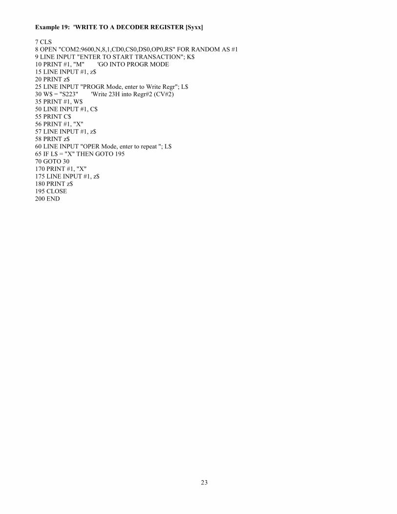
Example 19: 'WRITE TO A DECODER REGISTER [Syxx]
7 CLS 8 OPEN "COM2:9600,N,8,1,CD0,CS0,DS0,OP0,RS" FOR RANDOM AS #1 9 LINE INPUT "ENTER TO START TRANSACTION"; K$ 10 PRINT #1, "M" 'GO INTO PROGR MODE 15 LINE INPUT #1, z$ 20 PRINT z$ 25 LINE INPUT "PROGR Mode, enter to Write Regr"; L$ 30 W$ = "S223" 'Write 23H into Regr#2 (CV#2) 35 PRINT #1, W$ 50 LINE INPUT #1, C$ 55 PRINT C$ 56 PRINT #1, "X" 57 LINE INPUT #1, z$ 58 PRINT z$ 60 LINE INPUT "OPER Mode, enter to repeat "; L$ 65 IF L$ = "X" THEN GOTO 195 70 GOTO 30 170 PRINT #1, "X" 175 LINE INPUT #1, z$ 180 PRINT z$ 195 CLOSE 200 END

24
Decimal To Hexadecimal Conversion Chart Some decoder manuals, like Digitrax, use the Hexadecimal number system for showing values used during decoder programming. Your EasyDCC system uses conventional decimal numbers. To use a hexadecimal value, say from a decoder’s CV value table, you must convert it to a decimal number. Don’t be fooled by “normal” looking numbers such as 30. The 30 may actually be 30-hex which is the same as 48 decimal.
This chart is an easy way to convert. Find the Hexadecimal number in the column labeled Hex. Adjacent to the number is its decimal equivalent.
DEC HEX DEC HEX DEC HEX DEC HEX DEC HEX DEC HEX
0 00 43 2B 86 56 129 81 172 AC 215 D7
1 01 44 2C 87 57 130 82 173 AD 216 D8
2 02 45 2D 88 58 131 83 174 AE 217 D9
3 03 46 2E 89 59 132 84 175 AF 218 DA
4 04 47 2F 90 5A 133 85 176 B0 219 DB
5 05 48 30 91 5B 134 86 177 B1 220 DC
6 06 49 31 92 5C 135 87 178 B2 221 DD
7 07 50 32 93 5D 136 88 179 B3 222 DE
8 08 51 33 94 5E 137 89 180 B4 223 DF
9 09 52 34 95 5F 138 8A 181 B5 224 E0
10 0A 53 35 96 60 139 8B 182 B6 225 E1
11 0B 54 36 97 61 140 8C 183 B7 226 E2
12 0C 55 37 98 62 141 8D 184 B8 227 E3
13 0D 56 38 99 63 142 8E 185 B9 228 E4
14 0E 57 39 100 64 143 8F 186 BA 229 E5
15 0F 58 3A 101 65 144 90 187 BB 230 E6
16 10 59 3B 102 66 145 91 188 BC 231 E7
17 11 60 3C 103 67 146 92 189 BD 232 E8
18 12 61 3D 104 68 147 93 190 BE 233 E9
19 13 62 3E 105 69 148 94 191 BF 234 EA
20 14 63 3F 106 6A 149 95 192 C0 235 EB
21 15 64 40 107 6B 150 96 193 C1 236 EC
22 16 65 41 108 6C 151 97 194 C2 237 ED
23 17 66 42 109 6D 152 98 195 C3 238 EE
24 18 67 43 110 6E 153 99 196 C4 239 EF
25 19 68 44 111 6F 154 9A 197 C5 240 F0
26 1A 69 45 112 70 155 9B 198 C6 241 F1
27 1B 70 46 113 71 156 9C 199 C7 242 F2
28 1C 71 47 114 72 157 9D 200 C8 243 F3
29 1D 72 48 115 73 158 9E 201 C9 244 F4
30 1E 73 49 116 74 159 9F 202 CA 245 F5
31 1F 74 4A 117 75 160 A0 203 CB 246 F6
32 20 75 4B 118 76 161 A1 204 CC 247 F7
33 21 76 4C 119 77 162 A2 205 CD 248 F8
34 22 77 4D 120 78 163 A3 206 CE 249 F9
35 23 78 4E 121 79 164 A4 207 CF 250 FA
36 24 79 4F 122 7A 165 A5 208 D0 251 FB
37 25 80 50 123 7B 166 A6 209 D1 252 FC
38 26 81 51 124 7C 167 A7 210 D2 253 FD
39 27 82 52 125 7D 168 A8 211 D3 254 FE
40 28 83 53 126 7E 169 A9 212 D4 255 FF
41 29 84 54 127 7F 170 AA 213 D5 - -
42 2A 85 55 128 80 171 AB 214 D6 - -