r&s fs-k7 fm measurement demodulator for r&s fsx … · r&s fsx software manual...
TRANSCRIPT

R&S®FS-K7FM Measurement Demodulator for R&S FSx Software Manual
1141.1821.42 – 07
Test
andM
easu
reme
nt
Softw
areM
anua
l

The Software Manual R&S®FS-K7 describes the following Options:
R&S®FS-K7
© 2014 Rohde & Schwarz GmbH & Co. KG
81671 Munich, Germany
Subject to change – Data without tolerance limits is not binding.
R&S® is a registered trademark of Rohde & Schwarz GmbH & Co. KG.
Trade names are trademarks of the owners.
The following abbreviations are used throughout this manual:
R&S®FS-K7 is abbreviated as R&S FS-K7.

R&S FS-K7 Table of Contents
Software Manual 1141.1821.42 - 07 I-1
Table of Contents 1 Introduction ......................................................................................... 1
1.1 Circuit Description - Block Diagrams ........................................................................ 1
1.2 Further Characteristics ............................................................................................... 4
1.2.1 IF Bandwidth .................................................................................................................. 4
1.2.2 Demodulation Bandwidth ............................................................................................... 4
1.2.3 AF Trigger ...................................................................................................................... 5
1.2.4 Stability of Measurement Results .................................................................................. 5
2 Settings of the FM Demodulator ........................................................ 6
2.1 FM Demodulator Main Menu ....................................................................................... 6
2.1.1 Selection of Filter and Deemphasis – AF FILTER Menu ............................................... 9
2.1.2 Selection of Display Mode – RESULT DISPLAY Menu...............................................12
2.1.3 Scaling of Measurement Results – RANGE Menu ......................................................17
2.1.4 Scaling Functions for FM, PM and AM Result Display ................................................17
2.1.5 Scaling Functions for Result Displays with Level Display ...........................................20
2.2 FREQ Key ...................................................................................................................21
2.3 SPAN Key ...................................................................................................................22
2.4 AMPT Key ...................................................................................................................24
2.5 BW Key .......................................................................................................................24
2.6 TRIG Key .....................................................................................................................26
2.7 MKR Key .....................................................................................................................30
2.8 MKR Key .................................................................................................................31
2.9 MKR FCTN Key ...........................................................................................................31
2.10 MEAS Key ...................................................................................................................32
2.11 Other Keys ..................................................................................................................32
3 Multicarrier Phase Measurement ..................................................... 33
3.1 Orthogonal Method ....................................................................................................33
3.2 Flattop Method ...........................................................................................................34
3.3 Group Delay Measurements .....................................................................................34
3.4 Settings –MC PHASE RESPONSE Menu .................................................................34
3.4.2 Selection of Result Display – RESULT DISPLAY Menu ............................................37
3.4.3 Scaling of Measurement Results –RANGE Menu .......................................................39

R&S FS-K7 Table of Contents
Software Manual 1141.1821.42 - 07 I-2
3.4.4 Scaling Functions for Result Displays with Phase Diagrams ......................................40
4 Remote Control - Description of Commands ................................. 41
4.1 Common Commands .................................................................................................41
4.2 CALCulate Subsystem ..............................................................................................41
4.2.1 CALCulate:ADEMod Subsystem ................................................................................41
4.2.2 CALCulate:DELTamarker Subsystem .........................................................................44
4.2.3 CALCulate:FEED Subsystem ......................................................................................45
4.2.4 CALCulate:FORMat Subsystem .................................................................................46
4.2.5 CALCulate:MARKer Subsystem ..................................................................................46
4.2.6 CALCulate:MARKer:FUNCtion:ADEMod Subsystem ..................................................47
4.2.7 CALCulate:UNIT Subsystem .......................................................................................53
4.3 DISPlay Subsystem ...................................................................................................54
4.4 INSTrument Subsystem ............................................................................................56
4.5 SENSe Subsystem .....................................................................................................56
4.5.1 [SENSe:]ADEMod Subsystem .....................................................................................57
4.5.2 [SENSe:]ADEMod:AM Subsystem ..............................................................................66
4.5.3 [SENSe:]ADEMod:FM Subsystem ...............................................................................75
4.5.4 [SENSe:]ADEMod:MCPHase Subsystem ...................................................................81
4.5.5 [SENSe:]ADEMod:PM Subsystem ..............................................................................82
4.5.6 [SENSe:]ADEMod:SPECtrum Subsystem ..................................................................87
4.5.7 [SENSe:]BANDwidth Subsystem .................................................................................94
4.5.8 [SENSe:]FILTer Subsystem ........................................................................................96
4.5.9 [SENSe:]FREQuency Subsystem ..............................................................................100
4.6 TRACe Subsystem ...................................................................................................100
4.7 TRIGger Subsystem ................................................................................................102
4.8 UNIT Subsystem ......................................................................................................106
4.9 Table of Softkeys and Hotkeys including Assignment of Remote-Control
Commands ...............................................................................................................107
4.9.1 FM Demodulator Main Menu .....................................................................................107
4.9.2 FREQ Key ..................................................................................................................110
4.9.3 SPAN Key ..................................................................................................................110
4.9.4 AMPT Key ..................................................................................................................111
4.9.5 BW Key ......................................................................................................................112

R&S FS-K7 Table of Contents
Software Manual 1141.1821.42 - 07 I-3
4.9.6 TRIG Key ...................................................................................................................112
4.9.7 MKR Key ....................................................................................................................112
4.9.8 MKR Key ...............................................................................................................113
4.9.9 MKR FCTN Key .........................................................................................................113
Index ................................................................................................ 114

R&S FS-K7 Introduction
Software Manual 1141.1821.42 - 07 1
1 Introduction The following chapters describe the new operating functions of the FM demodulator
option for Spectrum Analyzer R&S FSP. In the case of functions identical to those of
the base unit, reference is made to the relevant chapter in the base unit manual.
The following chapters describe the new operating functions of the FM demodulator
option for Spectrum Analyzer R&S FSP and R&S FSU. In the case of functions
identical to those of the basic unit, reference is made to the relevant chapter in the
basic unit manual.
The digital signal processing in R&S FSP, used in the analyzer mode for digital IF
filters, is also ideally suited for demodulating FM or AM signals.
The digital signal processing in R&S FSP and R&S FSU, used in the analyzer mode for
digital IF filters, is also ideally suited for demodulating FM or AM signals.
By sampling (digitization) already at the IF and digital downconversion to the baseband
(I/Q), the demodulator achieves maximum accuracy and temperature stability. There is
no evidence of typical errors of an analog downconversion and demodulation like AM
FM conversion, deviation error, frequency response or frequency drift at
DC coupling. Only the characteristics of the analog IF filter ahead of the A/D converter
need to be taken into consideration.
1.1 Circuit Description - Block Diagrams
Fig.1 shows the analyzer’s hardware from the IF to the processor. The IF filter is the
resolution filter of the spectrum analyzer, with a bandwidth range from 300 kHz to
10 MHz. The A/D converter samples the IF (20.4 MHz) at 32 MHz.
Lowpass filtering and reduction of the sampling rate follow the downconversion to the
complex baseband. The decimation depends on the selected demodulation bandwidth.
The output sampling rate is set in powers of 2 between 15.625 kHz and 32 MHz.
Useless oversampling at narrow bandwidths is avoided, saving computing time and
increasing the maximum recording time.
The I/Q data is stored in memories each comprising 128 k words. The hardware
triggering (external, IF power) controls the memory.
The I/Q data are stored in memories each comprising 512 k words. The hardware
triggering (external, IF power) controls the memory.
I Memory
128 k
Processor
Analog
IF filter
Bandwidths
300 kHz
1 MHz
3 MHz
10 MHz
Analyzer IF
20.4 MHzA
D
A/D
converter
32 MHz
sampling
clock
Digital down conversion
+ decimation
cos
sin
decimation
filtersNCO
20.4 MHz
Q Memory
128 k
sampling rate
32 MHz / 2n
n = 0 ... 11
Data aquisition hardware
I data
Q data
Trigger
Fig.1 Block diagram of analyzer signal processing

R&S FS-K7 Introduction
Software Manual 1141.1821.42 - 07 2
The software demodulator runs on the main processor of the analyzer. The
demodulation process is shown in Fig.2. All calculations are performed simultaneously
with the same I/Q data set. Magnitude (= amplitude) and phase of the complex I/Q
pairs are determined. The frequency result is obtained from the differential phase.
Software demodulator
Countermodulation
frequency
RF power
trace
carrier
power
lowpassInter-
polation
Q data
FFTRF spectrum
trace
I2 + Q2
AM demodulator
amplitude
arctan(Q / I) d / dt
phase frequency
FM demodulator
I data
Trace
Detector
Trace
Arithmetic
Trace
Arithmetic
PM
Detectors
&
Counter
+ peak
rms
- peak1/2 pk-pk
arctan(Q / I)phase
PM demodulator
Inter-
polation
Trace
Arithmetic
modulation
frequency
lowpass
Trace
Detector PM trace
AC Coupling
Frequency
offset
AC Coupling
Phase Offset
FM
Detectors
&
Counter
+ peak
rms
- peak1/2 pk-pk
Inter-
polation
Trace
Arithmetic
modulation
frequency
lowpass
Trace
Detector FM traceAC Coupling
Freq Offset
carrier
frequency
offset
phase
offset
FFTAF spectrum
trace
Trace
Arithmetic
AF trigger
frequency
calculation
modulation
frequency
AM
Detectors
&
Counter
+ peak
rms
- peak1/2 pk-pk
Inter-
polation
Trace
Arithmetic
modulation
frequency
Trace
DetectorAM trace
modulation
depth
lowpass+-
/
Fig.2 Block diagram of software demodulator

R&S FS-K7 Introduction
Software Manual 1141.1821.42 - 07 3
The AM-DC, PM-DC and FM-DC raw data of the demodulators is fed into the trace
arithmetic block that combines consecutive data sets. Possible functions are: Clear
Write, Max Hold, Min Hold and Average. The output data of the trace arithmetic can be
read via GPIB. The recording length corresponds to the selected sampling rate of 1 to
128 k samples.
The recording length corresponds to the selected sampling rate of 1 to 512 k samples.
501 samples are required for on-screen display. If less data is recorded, the missing
intermediate values are calculated by an interpolation filter.
If more than 501 samples are recorded, the interpolator becomes ineffective. In this
case the trace detector reduces the number of samples to 501.
501 samples (R&S FSU: 625 samples) are required for on-screen display. If less data
are recorded, the missing intermediate values are calculated by an interpolation filter.
If more than 501 (R&S FSU: 625) samples are recorded, the interpolator becomes
ineffective. In this case the trace detector reduces the number of samples to 501
(R&S FSU: 625).
The trace detector combines several samples according to the functions selectable:
Sample, Max Peak, Min Peak, Average, Autopeak, RMS. The zoom function does not
combine any samples, but selects a sequence of 501 samples from the data set.The
trace detector combines several samples according to the functions selectable:
Sample, Max Peak, Min Peak, Average, Autopeak, RMS. The zoom function does not
combine any samples, but selects a sequence of 501 (R&S FSU: 625) samples from
the data set.
The data from the trace detector is displayed on the screen and can be read out via
GPIB. They display level, phase versus time and/or frequency versus time.
In addition, important parameters are calculated:
A counter determines the modulation frequency for AM, PM and FM.
A lowpass filter suppresses the modulation frequency; the result is the average
power = carrier power with AM and the average frequency = carrier frequency
offset with FM. The deviation from the selected center frequency is displayed.
AC coupling is possible with FM and PM display. To this end, the carrier frequency
offset is subtracted from the FM DC data. In addition, the frequency deviation is
determined from the trace data. +Peak, -Peak, ½ Peak-Peak and RMS are
displayed.
Besides the demodulators, the spectrum of the I/Q data, the FM, the PM or the AM is
calculated using FFT. The spectrum always comprises 501 samples.
Besides the demodulators, the spectrum of the I/Q data is calculated using FFT. The
spectrum always comprises 501 (FSU: 625) samples.

R&S FS-K7 Introduction
Software Manual 1141.1821.42 - 07 4
1.2 Further Characteristics
1.2.1 IF Bandwidth
The analog IF filter improves the selectivity, but also causes signal distortions. The
filter is negligible if:
IF bandwidth 10 x (modulation frequency + frequency deviation)
IF bandwidths 3 MHz ensure sufficient image-frequency rejection.
If due to a wide signal bandwidth an IF bandwidth of 10 MHz has to be selected,
signals are not allowed to be in the range from 6 MHz to 9 MHz above the receive
frequency because they will be convoluted back into the useful band of 10 MHz.
1.2.2 Demodulation Bandwidth
Digital filters determine the demodulation bandwidth. This is not the 3 dB bandwidth
but the useful bandwidth which is distortion-free with regard to phase and amplitude.
Therefore the following formulas apply:
AM: demodulation bandwidth 2 x modulation frequency
FM: demodulation bandwidth 2 x (frequency deviation + modulation frequency)
PM: demodulation bandwidth 2 modulation frequency (1 + phase deviation)
If the center frequency of the analyzer is not set exactly to the signal frequency, the
demodulation bandwidth must be selected larger by the carrier offset, in addition to the
requirement described above. This also applies if FM or PM AC coupling has been
selected.
In general, the demodulation bandwidth should be as narrow as possible to improve
the S/N ratio. The residual FM caused by noise floor and phase noise increases
dramatically with the bandwidth, especially with FM ( REF _Ref305574188 \h Fig. 3).
Residual FM at RF <= 1 GHz
1
10
100
1000
10000
12,5 25 50 100 200 400 800 1600 2800 5000 10000
Demodulation bandwidth / kHz
Re
sid
ua
l F
M / H
z (
RM
S)
Fig. 3 Residual FM as a function of demodulation bandwidth

R&S FS-K7 Introduction
Software Manual 1141.1821.42 - 07 5
1.2.3 AF Trigger
The FM demodulator option allows triggering to the demodulated signal. The display is
stable if a minimum of five modulation periods are within the recording time.
In the AM and FM display, triggering is always DC-coupled. In the PM display,
triggering is either AC- or DC-coupled, depending on the type of coupling set.
Therefore triggering is possible directly to the point where a specific carrier level,
phase or frequency is exceeded or not attained. This is particularly helpful when
measuring transients if no external trigger signal is available.
1.2.4 Stability of Measurement Results
Despite amplitude and frequency modulation, the display of carrier power and carrier
frequency offset is stable.
This is achieved by a digital filter which sufficiently suppresses the modulation,
provided, however, that the measurement time is 3 x 1 / modulation frequency, i.e.
that at least three periods of the AF signal are recorded.
The mean carrier power for calculating the AM is also calculated with a digital filter that
returns stable results after a measurement time of 3 * 1 / modulation frequency, i.e.
at least three cycles of the AF signal must be recorded before a stable AM can be
show.

R&S FS-K7 Settings of the FM Demodulator
Software Manual 1141.1821.42 - 07 6
2 Settings of the FM Demodulator The FM DEMOD hotkey opens the menu for setting the FM demodulator functions.
Simultaneously, the FM demodulator is activated.
2.1 FM Demodulator Main Menu
FM DEMOD ON / OFF
AF FILTER
RESULT DISPLAY
RANGE
DEMOD BW
MEAS TIME
ZOOM
The softkeys visible in the RANGE submenu depend on the selected measurement
function (FM / PM / RF SPECTRUM / AF SPECTRUM).

R&S FS-K7 Settings of the FM Demodulator
Software Manual 1141.1821.42 - 07 7
FM DEMOD ON / OFF
The FM DEMOD ON / OFF softkey switches the FM demodulator on or off. The FM
demodulator default setting is OFF; however, when the FM DEMOD mode is selected,
the demodulator is switched on automatically.
Note:
The resolution bandwidth, video bandwidth and sweep time active before the
demodulator is switched on are restored when the demodulator is switched off.
Similarly, the trace operating mode and detector are restored (the FM demodulator
has separate trace settings).
Remote: INST:SEL ADEM
INST:NSEL 3
AF FILTER
The AF FILTER softkey opens the submenu for selecting high pass or low pass filters
and also a de-emphasis. (see chapter "Selection of Filter – AF FILTER Menu").
RESULT DISPLAY
The RESULT DISPLAY softkey opens the submenu for selecting the measurement
function required (see chapter "Selection of Display Mode - RESULT DISPLAY
Menu").
RANGE
The RANGE softkey opens the submenu for setting the display range of the
measurement function selected (see chapter "Scaling of Measurement Results -
RANGE Menu").
DEMOD BW
The DEMOD BW softkey selects the demodulation bandwidth of the FM demodulator.
The demodulation bandwidth determines the sampling rate for recording the signal to
be analyzed.
The following table shows the relation between demodulation bandwidth and sampling rate:
Demodulation bandwidth Sampling rate Comment
120 MHz 256 MHz with R&S FSQ-B72 only
50/85 MHz (1)
128 MHz with R&S FSQ-B72 only
30 MHz 64 MHz with R&S FSQ only
18 MHz 32 MHz with R&S FSQ only
10 MHz 32 MHz
8 MHz 16 MHz This restriction only applies to R&S FSP and R&S
FSU without B72:
This filter is only flat for about 6 MHz, it has a 3 dB
decay at 7 MHz.
5 MHz 8 MHz

R&S FS-K7 Settings of the FM Demodulator
Software Manual 1141.1821.42 - 07 8
Demodulation bandwidth Sampling rate Comment
3 MHz 4 MHz
1.6 MHz 2 MHz
800 kHz 1 MHz
400 kHz 500 kHz
200 kHz 250 kHz
100 kHz 125 kHz
50 kHz 62.5 kHz
25 kHz 31.25 kHz
12.5 kHz 15.625 kHz
6.4 kHz 7.8125 kHz
3.2 kHz 3.90625 kHz
1.6 kHz 1.953125 kHz
800 Hz 976.5625 Hz
400 Hz 488.28125 Hz
200 Hz 244.140625 Hz
100 Hz 122.0703125 Hz
1) The demodulation bandwidth at a sampling rate of 128 MHz depends on the
center frequency that has been set. At a center frequency of ≤3.6 GHz, the
demodulation bandwidth is 50 MHz; at higher center frequencies, it is 85 MHz.
Remote: SENS:BAND:DEM 10MHz
MEAS TIME
The MEAS TIME softkey opens an editor for entering the measurement time of the FM
demodulator. The permissible value range depends on the demodulation bandwidth
selected.
Demodulation
bandwidth
Min. measurement
time
Max. measurement
time with AF trigger
Max. measurement
time with other trigger
120 MHz 3.90625 ns 425 s 510 s
50 / 85 MHz 7.8125 ns 850 s 1.0 ms
30 MHz 15.625 ns 1.7 ms 2.0 ms
18 MHz 31.25 ns 3.4 ms 4.1 ms
10 MHz 31.25 ns 3.4 ms 4.1 ms
8 MHz 62.5 ns 6.8 ms 8.2 ms
5 MHz 125 ns 13.6 ms 16.3 ms
3 MHz 250 ns 27.2 ms 32.6 ms
1.6 MHz 500 ns 54.4 ms 65.3 ms

R&S FS-K7 Settings of the FM Demodulator
Software Manual 1141.1821.42 - 07 9
Demodulation
bandwidth
Min. measurement
time
Max. measurement
time with AF trigger
Max. measurement
time with other trigger
800 kHz 1 s 109 ms 131 ms
400 kHz 2 s 218 ms 261 ms
200 kHz 4 s 435 ms 522 ms
100 kHz 8 s 870 ms 1.04 s
50 kHz 16 s 1.74 s 2.09 s
5 kHz 32 s 3.48 s 4.18 s
12.5 kHz 64 s 6.96 s 8.36 s
6.4 kHz 128 s 13.9 s 16.7 s
3.2 kHz 256 s 27.8 s 33.4 s
1.6 kHz 512 s 55.7 s 66.8 s
800 Hz 1.024 ms 111 s 133 s
400 Hz 2.048 ms 222 s 267 s
200 Hz 4.096 ms 445 s 534 s
100 Hz 8.192 ms 891 s 1069 s
Remote: SENS:ADEM:MTIM 62.5US
SENS:SWE:TIME 62.5US
ZOOM
In many cases, the number of recorded test points exceeds by far the number of
available pixels. Therefore several test points are combined to one pixel if the ZOOM
function is inactive.
If the ZOOM function is activated, a 1-to-1 allocation is selected, i.e. each pixel
corresponds to a recorded test point. The start of the zoom window can be determined
in the associated field by entering the time.
The zoom function is not available if the number of test points falls below the number
of pixels in the diagram (R&S FSP:501,R&S FSU/FSQ: 625).
Remote: SENS:ADEM:ZOOM ON SENS:ADEM:ZOOM:STARt 30US
2.1.1 Selection of Filter and Deemphasis – AF FILTER Menu
AF FILTER
The AF FILTER softkey opens the submenu for selecting high pass or low pass filters
and also a de-emphasis.
HIGH PASS AF FILTER
LOW PASS AF FILTER
DEEMPHASIS
WEIGHTING AF FILTER

R&S FS-K7 Settings of the FM Demodulator
Software Manual 1141.1821.42 - 07 10
HIGH PASS AF FILTER
The HIGH PASS AF FILTER softkey opens the submenu for selecting the high pass
filter.
The 20 Hz, 50 HZ and 300 HZ softkeys switch on a high pass filter with the given limit
to separate the DC component. The filters are indicated by the 3 dB cutoff frequency.
The filters are designed as 2nd-order Butterworth filter (12 dB/octave).
The NONE softkey deactivates the AF high pass filter. Default is NONE.
The R&S FSP requires the option R&S FSP-B70 for the high pass filter.
The high pass filter are active in the following demodulation bandwidth range:
20 Hz 100 Hz ≤ demodulation bandwidth ≤ 1.6 MHz
50 Hz 200 Hz ≤ demodulation bandwidth ≤ 4 MHz
300 Hz 800 Hz ≤ demodulation bandwidth ≤ 16 MHz
Remote: SENS:FILT:HPAS:STAT ON | OFF
SENS:FILT:HPAS:FREQ 20 Hz | 50 Hz |300 Hz
LOW PASS AF FILTER
The LOW PASS AF FILTER softkey opens the submenu for selecting the
low pass filter.
The 3 KHZ, 15 KHZ; 23 KHZ and 150 KHZ softkeys switch on a absolute low pass
filter. The filter are indicated by the 3 dB cutoff frequency. The 3 kHz and 15 kHz filters
are designed as 5th-order Butterworth filter (30 dB/octave). The 150 kHz filter is
designed as 8th-order Butterworth filter (48 dB/octave).
The 5 %, 10% and 25% HZ softkeys switch on a relative low pass filter. The filter (3
dB) can be selected in % of the demodulation bandwidth. The filters are designed as
5th-order Butterworth filter (30 dB/octave).
The NONE softkey deactivates the AF low pass filter. Default is NONE.
The R&S FSP requires the option R&S FSP-B70 for the absolute low pass filter 3 kHz,
15 kHz and 150 kHz. The relative low pass filters are always available.
The relative low pass filters are active for all demodulation bandwidth’s. The absolute
low pass filters are active in the following demodulation bandwidth range:
3 kHz 6.4 kHz ≤demodulationbandwidth ≤ 4 MHz
15 kHz 50 kHz ≤demodulationbandwidth ≤ 16 MHz
23 Hz 50 Hz ≤demodulationbandwidth ≤ 8 MHz
150 kHz 400 kHz ≤demodulation bandwidth ≤ 16 MHz
Remote: SENS:FILT:LPAS:STAT ON | OFF
SENS:FILT:LPAS:FREQu:REL 5 | 10 | 25
SENS:FILT:LPAS:FREQ 3 kHz | 15 kHz | 23kHz | 150 kHz

R&S FS-K7 Settings of the FM Demodulator
Software Manual 1141.1821.42 - 07 11
DEEMPHASIS
The DEEMPHASIS softkey opens the submenu for selecting the deemphasis.
The 25 us, 50 us, 75 us and 750 us softkeys switch on a de-emphasis with the given
time constant.
The NONE softkey deactivates the de-emphasis. Default is NONE.
The R&S FSP requires the option R&S FSP-B70 for the de-emphasis.
The de-emphasis is active in the following demodulation bandwidth range:
25 µs 25 kHz ≤ demodulation bandwidth ≤ 30 MHz
50 µs 6.4 kHz ≤ demodulation bandwidth ≤ 18 MHz
75 µs 6.4 kHz ≤ demodulation bandwidth ≤ 18 MHz
750µs 800 Hz ≤ demodulation bandwidth ≤ 4 MHz
The following table shows the required demodulation bandwidth for an error less than
0.5 dB up to a maximum AF frequency.
Deemphasis 25 µs 50 µs 75 µs 750 µs
Maximum AF Frequency
25 kHz 12 kHz 8 kHz 800 Hz
Required demodulation bandwidth
200 kHz 100 kHz 50 kHz 6.4 kHz
For higher AF frequencies the demodulation bandwidth must be increased.
Remote: SENS:FILT:DEMP:STAT ON | OFF
SENS:FILT:DEMP:TCON 25 us | 50 us | 75 us | 750 us
WEIGHTING AF FILTER
The WEIGHTING AF FILTER softkey opens the submenu for selecting the weighting
filter.
NONE
CCITT
CCIR UNWEIGHTED
CCIR WEIGHTED
A WEIGHTED
NONE
The NONE softkey deactivates the weighting filter. This is the default setting.
Remote: ---
CCITT
The CCITT softkey switches on a CCIT P.53 weighting filter. The weighting filter is
active in the following demodulation bandwidth range:
20 kHz ≤ demodulation bandwidth ≤ 3 MHz
Remote: SENS:FILT:CCIT:STAT ON | OFF

R&S FS-K7 Settings of the FM Demodulator
Software Manual 1141.1821.42 - 07 12
CCIR UNWEIGHTED
The CCIR UNWEIGHTED softkey switches on the CCIR unweighted filter, which is the
combination of the 20 Hz highpass and 23 kHz low pass filter. The weighting filter is
active in the following demodulation bandwidth range:
50 kHz ≤ demodulation bandwidth ≤ 1.6 MHz
Remote: SENS:FILT:CCIR:UNW:STAT ON | OFF
CCIR WEIGHTED
The CCIR WEIGHTED softkey switches on the CCIR weighted The weighting filter is
active in the following demodulation bandwidth range:
100 kHz ≤ demodulation bandwidth ≤ 3 MHz
Remote: SENS:FILT:CCIR:WEIG:STAT ON | OFF
A WEIGHTED
The A WEIGHTED softkey switches on the A weighted filter. The weighting filter is
active in the following demodulation bandwidth range:
100 kHz ≤ demodulation bandwidth ≤ 800 kHz
Remote: SENS:FILT:AWE:STAT ON | OFF
2.1.2 Selection of Display Mode – RESULT DISPLAY Menu
In order to display the measurement results the screen is divided in two halves:
In the upper half, the measurement results are displayed as a trace, in the lower half
the results of additional evaluation functions are shown. The RESULT DISPLAY
softkey allows the user to select the measurement results to be displayed.
RESULT DISPLAY
The RESULT DISPLAY softkey opens a submenu for selecting the measurement
result to be displayed.
The demodulated FM, PM or AM signal, the RF signal in the time domain or the RF or
AF frequency spectrum determined via FFT can be selected for display.
All displays are determined from the I/Q data set recorded for the measurement. In
SINGLE SWEEP mode, the single data set recorded can be evaluated in all displays
simply by switching the result display.
FM
PM
AM
RF POWER
RF SPECTRUM
AF SPECTRUM
SELECT TRACE
FULL SIZE DIAGRAM
R&S FS-K7 Settings of the FM Demodulator
Software Manual 1141.1821.42 - 07 13
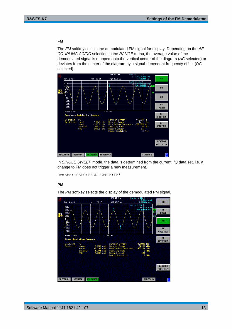
FM
The FM softkey selects the demodulated FM signal for display. Depending on the AF
COUPLING AC/DC selection in the RANGE menu, the average value of the
demodulated signal is mapped onto the vertical center of the diagram (AC selected) or
deviates from the center of the diagram by a signal-dependent frequency offset (DC
selected).
In SINGLE SWEEP mode, the data is determined from the current I/Q data set, i.e. a
change to FM does not trigger a new measurement.
Remote: CALC:FEED 'XTIM:FM'
PM
The PM softkey selects the display of the demodulated PM signal.
R&S FS-K7 Settings of the FM Demodulator
Software Manual 1141.1821.42 - 07 14
In SINGLE SWEEP mode, the data is determined from the current I/Q data set, i.e. a
change to PM does not trigger a new measurement.
Remote: CALC:FEED 'XTIM:PM'
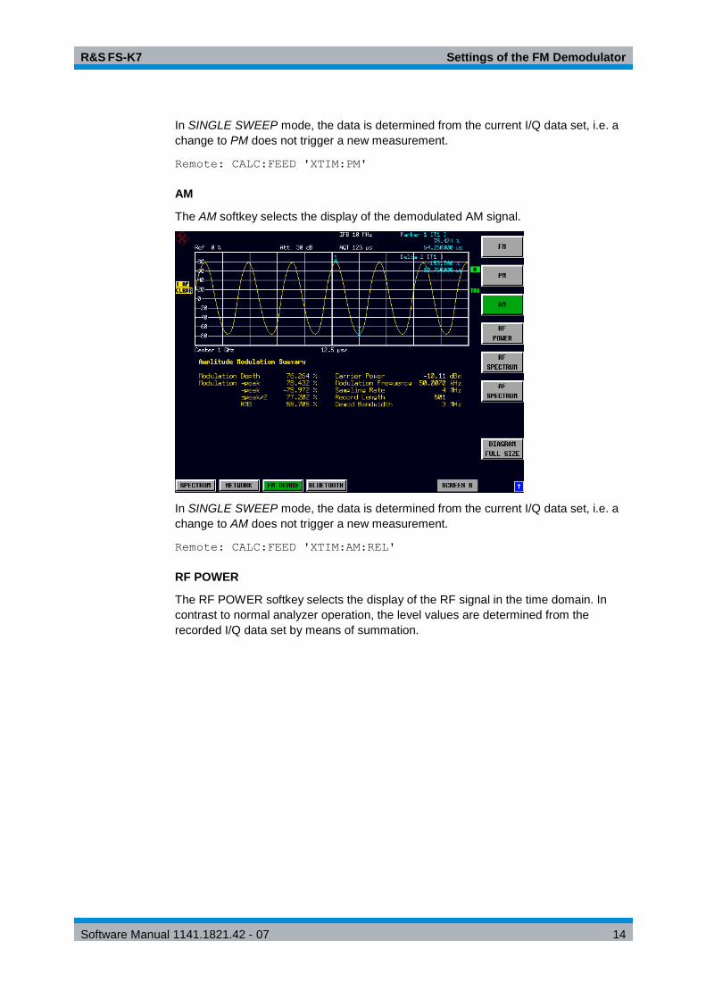
AM
The AM softkey selects the display of the demodulated AM signal.
In SINGLE SWEEP mode, the data is determined from the current I/Q data set, i.e. a
change to AM does not trigger a new measurement.
Remote: CALC:FEED 'XTIM:AM:REL'
RF POWER
The RF POWER softkey selects the display of the RF signal in the time domain. In
contrast to normal analyzer operation, the level values are determined from the
recorded I/Q data set by means of summation.

R&S FS-K7 Settings of the FM Demodulator
Software Manual 1141.1821.42 - 07 15
In SINGLE SWEEP mode, the data is determined from the current I/Q data set, i.e. a
change to RF POWER does not trigger a new measurement.
Remote: CALC:FEED 'XTIM:RFP'
RF SPECTRUM
The RF SPECTRUM softkey selects the RF signal in the frequency domain for display.
In contrast to normal spectrum analyzer operation, the measured values are
determined using FFT from the recorded I/Q data set.
In SINGLE SWEEP mode, the data is determined from the current I/Q data set, i.e. a
change to SPECTRUM does not trigger a new measurement.
Remote: CALC:FEED 'XTIM:SPECTRUM'

R&S FS-K7 Settings of the FM Demodulator
Software Manual 1141.1821.42 - 07 16
AF SPECTRUM
The AF SPECTRUM softkey selects the display of the AF spectrum. The AF spectrum
can be calculated from the FM signal, PM signal or the RF signal in the time domain.
The softkey is not available if the RF spectrum display is selected.
In SINGLE SWEEP mode, the data is determined from the current I/Q data set, i.e. a
change to AF SPECTRUM does not trigger a new measurement.
Remote: CALC:FEED 'XTIM:FM:AFSP'
CALC:FEED 'XTIM:PM:AFSP'
CALC:FEED 'XTIM:AM:AFSP'
CALC:FEED 'XTIM:RFP:AFSP'
SELECT TRACE
The SELECT TRACE softkey selects the trace, the data of which is to be displayed in
the lower half of the screen.
Remote: --
FULL SIZE DIAGRAM
The FULL SIZE DIAGRAM switches the diagram to full screen size.
Remote: DISP:SIZE LARG

R&S FS-K7 Settings of the FM Demodulator
Software Manual 1141.1821.42 - 07 17
2.1.3 Scaling of Measurement Results – RANGE Menu
RANGE
RANGE
DEVIATION
PER DIV
REFERENCE
POSITION
REFERENCE
VALUE
AF COUP
AC DC
DEVIATION
LIN LOG
DB
PER DIV
RF POWER
PER DIV
MAX DISP
RF POWER
RANGE
LINEAR
RANGE
LOG MANUAL
RANGE
LINEAR %
RANGE
LINEAR dB
FM
FM AF Spectrum
PM
PM AF Spectrum
AM
AM AF Spectrum
RF Power
RF Power AF Spectrum
RF Spectrum
Result Display:
PM UNIT
RAD DEG
UNIT
PHASE WRAP
ON OFF
ZERO PHASE
REF POS
THD UNIT
% DB
The RANGE softkey opens a submenu for determining the diagram scaling for the
selected measurement.
The softkeys visible depend on the selected measurement function (FM / RF POWER
/PM / RF SPECTRUM):
2.1.4 Scaling Functions for FM, PM and AM Result Display
DEVIATION PER DIV
The DEVIATION PER DIV softkey allows the phase or frequency deviation to be
displayed in the range 1 Hz/div to 1 MHz/div with the FM display and in the range
0.0001 rad/div to 1000 rad/div with the PM display.
To prevent corruption of the measurement results, the IF bandwidth of the analyzer
must be larger than the maximum frequency deviation plus modulation frequency (IF
BANDWIDTH softkey in the FM DEMOD menu).
The softkey is not available in the AF spectrum display of the FM or PM signal, as
scaling in this case is performed via the DB PER DIV and REFERENCE VALUE
softkeys.
Remote: DISP:WIND:TRAC:Y:PDIV 50kHz
REFERENCE POSITION
The REFERENCE POSITION softkey determines the position of the reference line for
the phase or frequency deviation on the y axis of the diagram. In the default setting of
the analyzer, this line corresponds to a frequency deviation of 0 Hz for the display of
the FM signal or to a phase deviation of 0 rad for the display of the PM signal.

R&S FS-K7 Settings of the FM Demodulator
Software Manual 1141.1821.42 - 07 18
The position is entered as a percentage of the diagram height with 100 %
corresponding to the upper diagram border. The default setting is 50 % (diagram
center) for the display of the PM or FM signal and 100% (upper diagram border) for the
AF spectrum display of the PM or FM signal.
Remote: DISP:WIND:TRAC:Y:RPOS 50PCT
REFERENCE VALUE
The REFERENCE VALUE softkey determines the frequency or phase deviation at the
reference line of the y axis. The reference value is set separately for each display of
the PM and FM signal and the AF spectrum of the PM and FM signal.
FM signal display:
The reference value makes it possible to take individual frequency offsets into account
in the trace display (in contrast, the AF COUP AC/DC softkey permits automatic
correction by the average frequency offset of the signal).
Values between 0 and 10 MHz can be selected. The softkey is not available if the AF
COUP AC function has been activated.
AF spectrum display of the FM signal:
In the default setting, the reference value defines the FM deviation at the upper
diagram border.
Values between 0 and 10 MHz can be selected.
PM signal display:
The reference value makes it possible to take individual phase offsets into account in
the trace display (in contrast, the AF COUP AC/DC softkey permits automatic
correction by the average phase offset of the signal).
Values between 0 and 10000 rad can be selected. The softkey is not available if the
AF COUP AC function has been activated.
AF spectrum display of the PM signal:
In the default setting, the reference value defines the PM deviation at the upper
diagram border.
Values between 0 and 10000 rad can be selected.
Remote: DISP:WIND:TRAC:Y:RVAL 0 HZ
AF COUP AC/DC
The AF COUP AC/DC softkey controls the automatic correction of the frequency offset
and phase offset of the input signal:
FM signal display:
If DC is selected, the absolute frequency is displayed, i.e. an input signal with an
offset relative to the center frequency is not displayed symmetrically with respect to
the zero line.

R&S FS-K7 Settings of the FM Demodulator
Software Manual 1141.1821.42 - 07 19
If AC is selected, the frequency offset is automatically corrected, i.e. the trace is
always symmetric with respect to the zero line.
PM signal display:
If DC is selected, the phase runs according to the existing frequency offset. In
addition, the DC signal contains a phase offset of ±π.
If AC is selected, the frequency offset and phase offset are automatically corrected,
i.e. the trace is always symmetric with respect to the zero line.
The softkey is not available with the AF spectrum display of the FM or PM signal.
Remote: SENS:ADEM:AF:COUP DC
ZERO PHASE REF POS
The ZERO PHASE REF POS softkey defines the position at which the phase of the
PM-demodulated signal is set to 0 rad. The entry is made with respect to time. In the
default setting, the first measured value is set to 0 rad.
This softkey is available only in the PM display with DC coupling.
Remote: SENS:ADEM:PM:RPO:X 10us
DEVIATION LIN/LOG
The DEVIATION LIN/LOG softkey switches between logarithmic and linear display of
the frequency deviation or phase deviation or modulation depth (AM).
The softkey is only available in the AF spectrum deviation of the FM or PM or AM signal.
Remote: DISP:WIND:TRAC:Y:SPAC LOG
DB PER DIV
The DB PER DIV softkey makes it possible to select the FM or PM deviation or
modulation depth to be displayed in the range 0.1 dB/div to 20 dB/div.
The softkey is not available if linear display is set.
Remote: DISP:WIND:TRAC:Y:PDIV 5DB
PHASE WRAP ON/OFF
The PHASE WRAP ON/OFF softkey activates/deactivates phase wrap.
ON The phase will be displayed in the range ±180° (±π). For example, if the phase
exceeds +180°, 360° is subtracted from the phase value, with the display thus
showing >-180°.
OFF The phase will not be wrapped.
This softkey in available in the PM signal displays.
Remote: CALC:FORM PHAS | UPH
UNIT
The UNIT softkey opens the submenu for selecting units.

R&S FS-K7 Settings of the FM Demodulator
Software Manual 1141.1821.42 - 07 20
PM UNIT RAD/DEG
The PM UNIT RAD/DEG softkey is used to select the unit for displaying PM signals.
Remote: UNIT:ANGL RAD
THD UNIT %/DB
The THD UNIT %/DB softkey selects between % and dB for displaying the THD
measurement result.
Remote: UNIT:THD PCT | DB
FUND FREQ MANUAL / FUND FREQ AUTO
The FUND FREQ MANUAL / FUND FREQ AUTO softkeys switches between
automatic or manual selection of the fundamental frequency used for the SINAD and
THD calculations. With automatic selection the peak in the AF spectrum is used as the
fundamental frequency.
When switching from AUTO to MANUAL the current modulation frequency result is
used as a default if the measurement result is available at this time.
These softkeys are available, if result AF SPECTRUM is switched on.
Remote: CALC:ADEM:THD:FREQ:FUND:AUTO ON | OFF
CALC:ADEM:THD:FREQ:FUND:VALue <numeric value>
2.1.5 Scaling Functions for Result Displays with Level Display
MAX DISP RF POWER
The MAX DISP RF POWER determines the maximum RF power to be displayed. The
selected value affects only the display. The reference level determines the dynamic
range limit of the analyzer’s A/D converter. If the input signal exceeds the selected
reference level, the measurement results are impaired by A/D converter overloading. If
a value higher than the reference level is selected for MAX DISP RF POWER, the
dynamic range limit (= reference level) is highlighted by a red line on the screen:
POS x dBm
Remote: DISP:WIND:TRAC:Y:RVAL 10 DBM
RF POWER LOG/LIN
The RF POWER LOG/LIN
softkey allows the user to select logarithmic or linear level display.
Remote: DISP:WIND:TRAC:Y:SPAC LOG
RF POWER PER DIV
The RF POWER PER DIV softkey determines the RELATIVE power between two
divisions on the y axis of the diagram.
Remote: DISP:WIND:TRAC:Y:PDIV 10 DB

R&S FS-K7 Settings of the FM Demodulator
Software Manual 1141.1821.42 - 07 21
RANGE LINEAR
The RANGE LINEAR softkey is identical to the softkey of the base unit.
RANGE LINEAR
The RANGE LINEAR softkey is identical to the softkey of the base unit.
RANGE LINEAR %
The RANGE LINEAR % softkey is identical to the softkey of the base unit.
RANGE LINEAR dB
The RANGE LINEAR dB softkey is identical to the softkey of the base unit.
RANGE LOG MANUAL
The RANGE LOG MANUAL softkey is identical to the softkey of the base unit.
2.2 FREQ Key
Span <> 0 Span = 0
FREQ CENTER
CF-
STEPSIZE
0.1 * SPAN
0.5 * SPAN
x * SPAN
= CENTER
0.1 * RBW
0.5 * RBW
x * RBW
= CENTER
MANUAL MANUAL
AF CENTER
AF START
AF STOP
SINGLE
AUTOTUNE
The FREQ menu functions are identical to those of the base unit.
If the AF spectrum display is active, the AF CENTER, AF START and AF STOP
softkeys, with which the displayed frequency range is defined within the demodulation -
bandwidth, are also available.

R&S FS-K7 Settings of the FM Demodulator
Software Manual 1141.1821.42 - 07 22
SINGLE AUTOTUNE
This softkey activates an automatic signal search.
Remote: SENS:FREQ:CW:AFC ONC
AF CENTER
The AF CENTER softkey allows the user to select the center frequency within the AF
spectrum.
Remote: SENS:ADEM:AF:CENT 1MHZ
AF START
The AF START softkey allows the user to select the start frequency within the AF
spectrum.
Remote: SENS:ADEM:AF:STAR 0HZ
AF STOP
The AF STOP softkey allows the user to select the stop frequency within the AF
spectrum.
The maximum AF stop frequency corresponds to half the demodulation bandwidth.
Remote: SENS:ADEM:AF:STOP 2MHZ
2.3 SPAN Key
The SPAN menu allows the user to select the frequency range to be displayed if the
spectrum displays of the FM demodulator are active.
AF Spectrum RF Spectrum
AF SPAN FREQUENCY SPAN
AF FULL SPAN FULL SPAN
DEMOD BW DEMOD BW
AF SPAN
The AF SPAN softkey allows the user to select the frequency range if the AF spectrum
displays are active.
Values between the sampling rate/200 and the demodulation bandwidth/2 can be
selected.
Remote: SENS:ADEM:AF:SPAN 2.5 MHz
FREQUENCY SPAN
The FREQUENCY SPAN softkey allows the user to select the frequency range if the
RF SPECTRUM display is active.
Values between the sampling rate/200 and the demodulation bandwidth/2 can be selected.
Remote: SENS:ADEM:SPEC:SPAN:ZOOM 5 MHz

R&S FS-K7 Settings of the FM Demodulator
Software Manual 1141.1821.42 - 07 23
AF FULL SPAN
The AF FULL SPAN softkey sets the maximum frequency range if the AF spectrum
displays are active.
The maximum frequency range corresponds to half the demodulation bandwidth.
Remote: SENS:ADEM:AF:SPAN:FULL
FULL SPAN
The FULL SPAN softkey sets the maximum frequency range if the RF spectrum
display is active.
The maximum frequency range corresponds to the demodulation bandwidth.
Remote: ADEM:SPEC:SPAN:ZOOM MAX
DEMOD BW
The demodulation bandwidth of the FM demodulator is selected with the DEMOD BW
softkey.
Note:
The function is identical to the function of the DEMOD BW softkey in the FM
DEMOD main menu.
Remote: SENS:BAND:DEM 10MHz
MEAS TIME
The MEAS TIME softkey opens the input field for the measurement time of the FM
demodulator.
Note:
The function is identical to the function of the MEAS TIME softkey in the FM
DEMOD main menu.
Remote: SENS:ADEM:MTIM 62.5US
SENS:SWE:TIME 62.5US

R&S FS-K7 Settings of the FM Demodulator
Software Manual 1141.1821.42 - 07 24
2.4 AMPT Key
REF LEVEL
RF ATTEN
AUTO
RANGE
LOG 100 dB
RANGE
LINEAR
RANGE
LOG MANUAL
REF LEVEL
POSITION
REF LEVEL
OFFSET
RF ATTEN
MANUAL
RF INPUT50W 75W
EL ATTEN
AUTO
EL ATTEN
MANUAL
EL ATTEN
OFF
Option
FSP-B25
Option
FSP-B25
Option
FSP-B25
AMPT
RANGE
LINEAR %
RANGE
LINEAR dB
The AMPT menu functions are identical to those of the base unit.
The following functions are only available with level displays:
RANGE LOG 100 dB
RANGE LOG MANUAL
RANGE LINEAR
The REF LEVEL value defines the clipping level of the A/D converter and must
therefore be set greater than or equal to the maximum power of the signal to be
analyzed.
2.5 BW Key
The BW menu comprises all functions relating to the band limiting of the analyzed
signal.
RES BW
IF BW AUTO
IF BW MANUAL
DEMOD BW
MEAS TIME

R&S FS-K7 Settings of the FM Demodulator
Software Manual 1141.1821.42 - 07 25
RES BW
If the Spectrum result display is active, the RES BW softkey selects the resolution
bandwidth for the signal displayed. Note that these resolution bandwidths are obtained
by means of FFT filters from 1 Hz to 10 MHz.
Note:
The softkey is available only if the RF SPECTRUM or AF SPECTRUM result
display is active.
The IF bandwidth is limited by analog LC filters using the IF BW MANUAL and IF
BW AUTO softkeys.
Remote: SENS:ADEM:SPEC:BAND:RES 10 kHz
IF BW AUTO
The IF BW AUTO softkey couples the IF bandwidth of the analyzer (i.e. the bandwidth
of the analog LC filters) to the selected demodulation bandwidth.
Remote: SENS:BAND:RES:AUTO ON
IF BW MANUAL
The IF BW MANUAL softkey allows the IF bandwidth of the analyzer to be entered (i.e. the
bandwidth of the analog filters). Bandwidths from 300 kHz to 10 MHz can be selected.
Remote:SENS:BAND:RES 1 MHz
Note:
Manual setting of the IF bandwidth is usually not required. If an IF bandwidth is set
that is narrower than the value defined by AUTO coupling,
- the RF frequency response is identical to that of the IF filter if the spectrum
display is active,
- an AF frequency response corresponding to a lowpass filter equivalent to the
IF filter occurs in the case of FM demodulation.
DEMOD BW
The demodulation bandwidth of the FM demodulator is selected via the DEMOD BW
softkey.
Note:
The function is identical to that of the DEMOD BW softkey in the FM DEMOD main menu.
Remote: SENS:BAND:DEM 10MHz
MEAS TIME
The MEAS TIME softkey opens the editor for entering the data-recording time of the
FM demodulator.
Note:
The function is identical to that of the MEAS TIME softkey in the FM DEMOD main
menu.
Remote: SENS:ADEM:MTIM 62.5US
SENS:SWE:TIME 62.5US

R&S FS-K7 Settings of the FM Demodulator
Software Manual 1141.1821.42 - 07 26
2.6 TRIG Key
The TRIG key opens a menu for setting the different trigger sources and for selecting
the trigger polarity. The active trigger mode is indicated by highlighting the associated
softkeys.
To indicate that a trigger mode other than FREE RUN has been set, the TRG
enhancement label is displayed on the screen. If two measurement windows are
displayed, TRG is indicated next to the window in question.
FREE RUN
DEMOD SIGNAL
FM SIGNAL
PM SIGNAL
AM SIGNAL
RF POWER SIGNAL
EXTERN
IF POWER
TRIGGER OFFSET
POLARITY POS/NEG
FREE RUN
The FREE RUN softkey activates the free-running sweep, i.e. the measurement start is
not triggered explicitly. When a measurement is completed, the next one starts
immediately. FREE RUN is the default setting.
Remote: TRIG:SOUR IMM
DEMOD SIGNAL
The DEMOD SIGNAL softkey opens the menu for selecting the various trigger
sources.
FM SIGNAL
With a modulated signal, the trigger source that is selected with the FM SIGNAL
softkey is the point at which a specific absolute phase is reached by the input signal.
The associated trigger threshold can be entered simultaneously.
Measurement is triggered if the selected threshold is exceeded. A periodic signal
modulated onto the carrier frequency can be displayed in this way.
Note:
For triggering with the FM SIGNAL trigger source to be successful, the
measurement time must cover at least five periods of the audio signal.
The triggering responds to the absolute frequency, i.e. it is always DC-coupled.
Remote: TRIG:SOUR FM
TRIG:LEV:FM 10 kHz
R&S FS-K7 Settings of the FM Demodulator
Software Manual 1141.1821.42 - 07 27
PM SIGNAL
With a modulated signal, the trigger source that is selected with the PM SIGNAL
softkey is the point at which a specific absolute frequency is reached. The associated
trigger threshold can be entered simultaneously.
Measurement is triggered if the selected threshold is exceeded. A periodic signal
modulated onto the carrier frequency can be displayed in this way.
Note:
For triggering with the PM SIGNAL trigger source to be successful, the
measurement time must cover at least five periods of the audio signal.
Triggering is either AC- or DC-coupled, depending on the AF COUPLING AC/DC
setting in the RANGE menu.
Remote: TRIG:SOUR PM
TRIG:LEV:PM 0.2 rad
AM SIGNAL
With a modulated signal, the trigger source that is selected with the AM SIGNAL
softkey is the point at which a specific modulation depth is reached. The associated
trigger threshold can be entered simultaneously.
Measurement is triggered if the selected threshold is exceeded. A periodic signal
modulated onto the carrier frequency can be displayed in this way.
Note:
For triggering with the AM SIGNAL trigger source to be successful, the
measurement time must cover at least five periods of the audio signal.
Remote: TRIG:SOUR AMR
TRIG:LEV:AM:REL 0.2 rad
RF POWER SIGNAL
With a modulated signal (AF signal), the trigger source that is selected with the RF
POWER SIGNAL softkey is the point at which a specific signal level is reached. The
associated trigger threshold can be entered simultaneously.
Measurement is triggered if the selected threshold is exceeded. A periodic signal
modulated onto the carrier frequency can be displayed in this way.
Note:
The RF POWER SIGNAL trigger differs from the RF POWER trigger in that the AF
signal is taken into account rather than the RF signal.
For triggering with the AM trigger source to be successful, the measurement time
must cover at least five periods of the audio signal.
Remote: TRIG:SOUR AM
TRIG:LEV:AM –30 dBm
EXTERN
The EXTERN softkey activates triggering by a TTL signal at the EXT TRIGGER/GATE
input connector on the rear panel.

R&S FS-K7 Settings of the FM Demodulator
Software Manual 1141.1821.42 - 07 28
Remote: TRIG:SOUR EXT
SWE:EGAT:SOUR EXT
IF POWER
The IF POWER softkey activates triggering of measurement by means of signals
outside the measurement channel.
To this end, the R&S FSP uses a level detector on the second intermediate frequency.
The threshold of the level detector can be selected between -30 dBm and -10 dBm at
the input mixer.
The R&S FSU also uses a level detector on the second intermediate frequency. The
threshold of the level detector can be selected between –50 dBm and
–10 dBm at the input mixer for R&S FSU.
This means that the input signal range within which the trigger responds can be
calculated as follows:
eampGainRFAttMixerlevelSignalInputeampGainRFAttMixerlevel PrPr maxmin
The bandwidth on the intermediate frequency is 10 MHz. The measurement is
triggered if the trigger threshold is exceeded by a signal in a range of 5 MHz around
the center frequency.
For R&S FSU the bandwidth on the intermediate frequency is 80 MHz, which means
that the measurement is triggered if the trigger threshold is exceeded in a range of 40
MHz around the center frequency.
This allows spurious signals to be measured, such as pulsed carriers, even if the
carrier itself is not within the display frequency range.
Remote: TRIG:SOUR IFP
SWE:EGAT:SOUR IF
RF POWER
The RF POWER softkey activates triggering of measurement by means of signals
outside the measurement channel.
To this end, the analyzer uses a level detector on the first intermediate frequency. The
threshold of the level detector can be selected between -50 dBm and -10 dBm at the
input mixer. This means that the input signal range within which the trigger responds
can be calculated as follows:
eampGainRFAttMixerlevelSignalInputeampGainRFAttMixerlevel PrPr maxmin
The bandwidth on the intermediate frequency is 80 MHz. The measurement is
triggered if the trigger threshold is exceeded by the set frequency in a 40 MHz range.
This allows spurious to be measured, such as pulsed carriers, even if the carrier itself
is not within the display frequency range.
Note:
The function is only available with option TV and RF Trigger R&S FSP-B6.
Remote: TRIG:SOUR RFP
SWE:EGAT:SOUR RFP
R&S FS-K7 Settings of the FM Demodulator
Software Manual 1141.1821.42 - 07 29
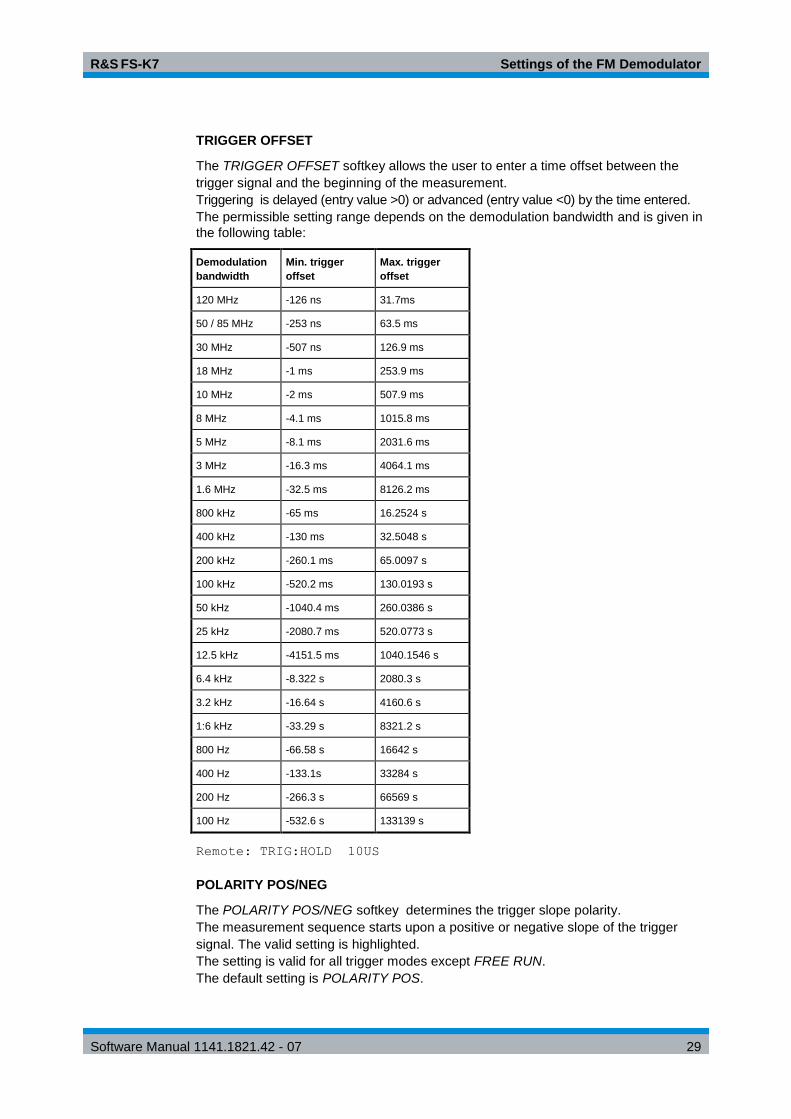
TRIGGER OFFSET
The TRIGGER OFFSET softkey allows the user to enter a time offset between the
trigger signal and the beginning of the measurement.
Triggering is delayed (entry value >0) or advanced (entry value <0) by the time entered.
The permissible setting range depends on the demodulation bandwidth and is given in
the following table:
Demodulation
bandwidth
Min. trigger
offset
Max. trigger
offset
120 MHz -126 ns 31.7ms
50 / 85 MHz -253 ns 63.5 ms
30 MHz -507 ns 126.9 ms
18 MHz -1 ms 253.9 ms
10 MHz -2 ms 507.9 ms
8 MHz -4.1 ms 1015.8 ms
5 MHz -8.1 ms 2031.6 ms
3 MHz -16.3 ms 4064.1 ms
1.6 MHz -32.5 ms 8126.2 ms
800 kHz -65 ms 16.2524 s
400 kHz -130 ms 32.5048 s
200 kHz -260.1 ms 65.0097 s
100 kHz -520.2 ms 130.0193 s
50 kHz -1040.4 ms 260.0386 s
25 kHz -2080.7 ms 520.0773 s
12.5 kHz -4151.5 ms 1040.1546 s
6.4 kHz -8.322 s 2080.3 s
3.2 kHz -16.64 s 4160.6 s
1:6 kHz -33.29 s 8321.2 s
800 Hz -66.58 s 16642 s
400 Hz -133.1s 33284 s
200 Hz -266.3 s 66569 s
100 Hz -532.6 s 133139 s
Remote: TRIG:HOLD 10US
POLARITY POS/NEG
The POLARITY POS/NEG softkey determines the trigger slope polarity.
The measurement sequence starts upon a positive or negative slope of the trigger
signal. The valid setting is highlighted.
The setting is valid for all trigger modes except FREE RUN.
The default setting is POLARITY POS.

R&S FS-K7 Settings of the FM Demodulator
Software Manual 1141.1821.42 - 07 30
Note:
The function is available only for detector boards with model index 3. Previous
boards ignore the setting.
Remote: TRIG:SLOP POS
2.7 MKR Key
ALL MARKER
OFF
MARKER 4
MARKER
NORM DELTA
MARKER 3
MARKER 2
MARKER 1MKR
The MKR menu functions are identical to those of the base unit.
Only the measurement result display is coupled to the active result display and is in Hz
if FM and FM AF spectrum are selected, in rad if PM and PM AF spectrum are
selected, or in dBm or dB if RF POWER, RF POWER AF spectrum and RF
SPECTRUM are selected.

R&S FS-K7 Settings of the FM Demodulator
Software Manual 1141.1821.42 - 07 31
2.8 MKR Key
NEXT PEAK
REF LEVEL
=MKR LVL
PEAK
EXCURSION
MKR MKR
SELECT
MARKER
CENTER
=MKR FREQ
SEARCH
LIMITS
MRK->TRACE
AMPLSPAN
PEAK MIN
NEXT
MIN RIGHT
FCTN
RIGHT
LIMIT
LEFT
LIMIT
THRESHOLD
SEARCH LIM
OFF
NEXT
PEAK LEFT
NEXT
PEAK RIGHT
NEXT
MIN LEFT
NEXT MIN
The MKR menu functions are identical to those of the base unit.
The function REF LEVEL = MKR LVL is not available if the FM result display is active.
2.9 MKR FCTN Key
MKR MKR
SELECT
MARKER
SHAPE FACT
60:3 60:6
MRK->TRACE
AMPTSPAN
PEAK
FCTN
The available MKR FCTN menu functions are identical to those of the base unit.

R&S FS-K7 Settings of the FM Demodulator
Software Manual 1141.1821.42 - 07 32
2.10 MEAS Key
The MEAS menu functions are not available in the FM DEMOD mode.
2.11 Other Keys
The functions of the other keys are identical to those of the base unit. Please refer to
the relevant chapters in the operating manual of the base unit.

R&S FS-K7 Multicarrier Phase Measurement
Software Manual 1141.1821.42 - 07 33
3 Multicarrier Phase Measurement
Multicarrier phase measurement is only supported by R&S FSQ and R&S FSG.
The Multicarrier Phase Measurement returns spectral magnitude and phase values of
an input signal consisting of several unmodulated carriers. These results can further be
used to calculate frequency response and group delay characteristics of radio
channels.
Two different measurement methods are implemented to calculate the level and phase
values versus frequency. The orthogonal method returns the result at the carrier
frequencies only and offers superior performance and accuracy. The flattop method
returns a more convenient spectrum plot showing also the transitions between the
carriers and should be selected to get a spectral overview.
3.1 Orthogonal Method
The sample frequency and the FFT length are internally chosen such that their ratio
equals the carrier spacing f .
Length FFT
Frequency Samplef
Thus all carriers are orthogonal to each other within an observation interval of one FFT
length and the FFT returns phase and level results exactly at the carrier frequencies.
Several FFT results are averaged according to the selected measurement time. The
FFT is preceded by a frequency correction to avoid intercarrier interference by
matching the carrier frequencies to the FFT grid.
FFTIQ-Data Level
Phase
Freq. Offset
EstimationNCO
Rectangular
Window
Fig. 4 Block diagram of the orthogonal measurement method
It is recommended to set the span according to the following equation:
f 1rriersNumberOfCaSpan .
R&S FS-K7 Multicarrier Phase Measurement
Software Manual 1141.1821.42 - 07 34
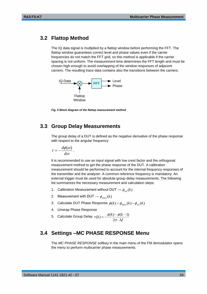
3.2 Flattop Method
The IQ data signal is multiplied by a flattop window before performing the FFT. The
flattop window guarantees correct level and phase values even if the carrier
frequencies do not match the FFT grid, so this method is applicable if the carrier
spacing is not uniform. The measurement time determines the FFT length and must be
chosen high enough to avoid overlapping of the window responses of adjacent
carriers. The resulting trace data contains also the transitions between the carriers.
FFTIQ-Data Level
Phase
Flattop
Window
Fig. 5 Block diagram of the flattop measurement method
3.3 Group Delay Measurements
The group delay of a DUT is defined as the negative derivative of the phase response
with respect to the angular frequency
d
d )( .
It is recommended to use an input signal with low crest factor and the orthogonal
measurement method to get the phase response of the DUT. A calibration
measurement should be performed to account for the internal frequency responses of
the transmitter and the analyzer. A common reference frequency is mandatory. An
external trigger must be used for absolute group delay measurements. The following
list summarizes the necessary measurement and calculation steps:
1. Calibration Measurement without DUT → )(kcal
2. Measurement with DUT → )(kmeas
3. Calculate DUT Phase Response )()()( kkk calmeas
4. Unwrap Phase Response
5. Calculate Group Delay f
kkk
2
)1()()(
3.4 Settings –MC PHASE RESPONSE Menu
The MC PHASE RESPONSE softkey in the main menu of the FM demodulator opens
the menu to perform multicarrier phase measurements.

R&S FS-K7 Multicarrier Phase Measurement
Software Manual 1141.1821.42 - 07 35
MC PHASE ON / OFF
MEAS METHOD
CARRIER SPACING
SPAN
MEASTIME AUTO
MEASTIME MANUAL
RESULT DISPLAY
The arrangement of the softkeys in the RANGE submenu depends on the set diagrams
(Magnitude vs Freq / Phase vs Freq / Phase Polar)..
MC PHASE ON / OFF
The MC PHASE ON / OFF softkey switches the multicarrier phase measurement on or
off.
Remote: SENS1:ADEM ON
SENS1:ADEM:MCPH:STAT ON
MEAS METHOD
The softkey opens a list box to select between the method based on orthogonal and
flattop-window measurement.

R&S FS-K7 Multicarrier Phase Measurement
Software Manual 1141.1821.42 - 07 36
MEAS METHOD
Orthogonal
Flattop
Remote: SENS1:ADEM:MCPH:METH ORTH
CARRIER SPACING
The CARRIER SPACING softkey defines the spacing between two carriers.
Note:
For the method based on flattop-window measurement, the carrier spacing is only
required to calculate the automatic measurement time.
Remote: SENS1:ADEM:MCPH:SPAC 100KHZ
SPAN
The SPAN softkey defines the number of carriers to be measured.
Example:
A span 3 * carrier spacing (f) is required to measure a signal with four carriers.
f
Center
Frequency
Span
f
Remote: SENS1:ADEM:SPEC:SPAN:MAX 3MHZ
MEASTIME AUTO
The MEASTIME AUTO softkey activates the automatic calculation of the recording
length.
Remote: SENS1:ADEM:MTIM:AUTO ON
MEASTIME MANUAL
The MEASTIME MANUAL softkey opens a data entry field to manually enter the
recording length.
Remote: SENS1:ADEM:MTIM 1ms
RESULT DISPLAY
The RESULT DISPLAY softkey opens the submenu to select the required
measurement function (s. section "Selection of Result Display – RESULT DISPLAY "
Menu).

R&S FS-K7 Multicarrier Phase Measurement
Software Manual 1141.1821.42 - 07 37
3.4.2 Selection of Result Display – RESULT DISPLAY Menu
The RESULT DISPLAY softkey opens a submenu to select the measurement result to
be displayed.
The magnitude or phase of the signal in the frequency domain or the phase in a polar
diagram can be selected.
All results are determined by the I/Q data set recorded for the measurement. In the
SINGLE SWEEP mode, the data set recorded once can be evaluated in all diagrams
by simply switching over the result display.
MAGNITUDE VS FREQ
PHASE VS FREQ
PHASE POLAR
POLAR DIAG START FREQ
POLAR DIAG STOP FREQ
MAGNITUDE VS FREQ
The MAGNITUDE VS FREQ softkey selects the level diagram of the signal in the
frequency domain.
Remote: CALC:FEED ‘XFR:SPEC:MAGN’
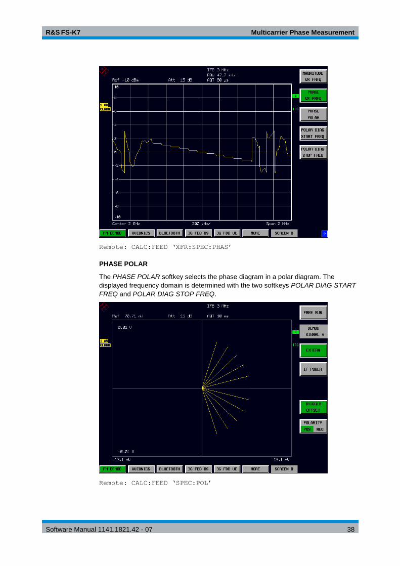
PHASE VS FREQ
The PHASE VS FREQ softkey selects the phase diagram of the signal in the frequency
domain.
R&S FS-K7 Multicarrier Phase Measurement
Software Manual 1141.1821.42 - 07 38
Remote: CALC:FEED ‘XFR:SPEC:PHAS’
PHASE POLAR
The PHASE POLAR softkey selects the phase diagram in a polar diagram. The
displayed frequency domain is determined with the two softkeys POLAR DIAG START
FREQ and POLAR DIAG STOP FREQ.
Remote: CALC:FEED ‘SPEC:POL’

R&S FS-K7 Multicarrier Phase Measurement
Software Manual 1141.1821.42 - 07 39
POLAR DIAG START FREQ
The POLAR DIAG START FREQ softkey determines the start frequency starting from
which the phases are displayed in the polar diagram. In the MAGNITUDE VS FREQ
and PHASE VS FREQ diagrams, the start frequency is characterized by a display line.
Remote: CALC:ADEM:MCPH:POL:FREQ:STAR 100MHz’
POLAR DIAG STOP FREQ
The POLAR DIAG STOP FREQ softkey determines the stop frequency up to which the
phases are displayed in the polar diagram. In the MAGNITUDE VS FREQ and PHASE
VS FREQ diagrams, the stop frequency is characterized by a display line.
Remote: CALC:ADEM:MCPH:POL:FREQ:STOP 120MHz’
3.4.3 Scaling of Measurement Results –RANGE Menu
RANGE
Magnitude vs FreqPhase vs Freq
Phase Polar
Result Display:
RF POWER
PER DIV
MAX DISP
RF POWER
RANGE
LINEAR
RANGE
LOG MANUAL
RANGE
LINEAR %
RANGE
LINEAR dB
Y PER DIV
REFERENCE
POSITION
REFERENCE
VALUE
PM UNIT
RAD DEG
The RANGE softkey opens a submenu to determine the diagram scaling for the
selected display.
The visible selection of the softkeys depends on the selected diagram (Magnitude vs
Freq / Phase vs Freq / Phase Polar).
The scaling of the level diagram (Magnitude vs Freq) is identical to the level diagrams
of analog demodulation (RF Power und RF Spectrum).
R&S FS-K7 Multicarrier Phase Measurement
Software Manual 1141.1821.42 - 07 40
3.4.4 Scaling Functions for Result Displays with Phase Diagrams
Y PER DIV
The Y PER DIV softkey determines the scaling of the Y axis for the two phase
diagrams (Phase vs Freq / Phase Polar).
To display the phase in the frequency domain, make the entry using the unit selected
by means of the PM UNIT RAD/DEG softkey.
In the polar diagram, the entry is made in Volt. The scaling of the X axis is coupled to
the Y axis in the polar diagram.
Remote: DISP:WIND:TRAC:Y:PDIV 0.5RAD
REFERENCE POSITION
The REFERENCE POSITION softkey determines the position of the reference line for
the phase diagram in the frequency domain. The default setting is 50 % (diagram
center).
Remote: DISP:WIND:TRAC:Y:RPOS 50PCT
REFERENCE VALUE
The REFERENCE VALUE softkey determines the value of the reference line for phase
diagram in the frequency domain. The basic setting is 0 rad.
Remote: DISP:WIND:TRAC:Y:RVAL 0RAD
PM UNIT RAD/DEG
The PM UNIT RAD/DEG softkey allows you to select the unit for displaying phase
values.
Remote: UNIT:ANGL RAD

R&S FS-K7 Remote Control - Description of Commands
Software Manual 1141.1821.42 - 07 41
4 Remote Control - Description of Commands The information in this chapter supplements and updates chapters 5 and 6 of the R&S
FSP manual. This chapter contains the new commands that apply specifically to option
R&S FS-K7 as well as the modified commands of the basic instrument provided they
are used by R&S FS-K7.
Every attempt was made to ensure the highest possible compatibility of the R&S FS-
K7 commands with those of analog demodulation of the FSE family. A few commands
were included in the command set for this reason only.
In the description of menu operation in chapter 2, each softkey is indicated with the
associated IEC/IEEE bus commands.
The measurements of the FM Demodulator mode are always carried out in screen A.
Therefore, the commands where the numeric suffix selects the screen must either start
with numeric suffix 1 (i.e. CALCulate1) or without a numeric suffix (i.e. CALCulate).
4.1 Common Commands
*OPT?
OPTION IDENTIFICATION QUERY queries the options included in the instrument
and returns a list of the installed options. The options are separated by commas. In
the response string, the identification of option R&S FS-K7 is indicated at position
32:
Example:
0,0,0,0,0,0,0,0,0,0,0,0,0,0,0,0,0,0,0,0,0,0,0,0,0,0,0,0,0,0,0
,K7,0,0,0,0,0,0,0,0
4.2 CALCulate Subsystem
4.2.1 CALCulate:ADEMod Subsystem
CALCulate1:ADEMod:MCPHase:POLar:FREQuency:STARt <numeric_value>
Multicarrier measurement: start frequency for range selection in polar diagram.
Example
SENS1:ADEM ON
'Switch on Ademod measurement.

R&S FS-K7 Remote Control - Description of Commands
Software Manual 1141.1821.42 - 07 42
SENS1:ADEM:MCPH:STAT ON
'Multicarrier measurement on.
CALC1:ADEM:MCPH:POL:FREQ:STAR:STAT ON
'Switch on start frequency.
CALC1:ADEM:MCPH:POL:FREQ:STAR 20GHZ
'Set start frequency.
Characteristics
*RST value: -
SCPI: device-specific
CALCulate1:ADEMod:MCPHase:POLar:FREQuency:STARt:STAT ON|OFF
Multicarrier measurement: activates start frequency for range selection in polar
diagram and activates display line in the frequency diagram
Example
SENS1:ADEM ON
'Switch on Ademod measurement.
SENS1:ADEM:MCPH:STAT ON
'Multicarrier measurement on.
CALC1:ADEM:MCPH:POL:FREQ:STAR:STAT ON"
'Start frequency to default, activate display line.
Characteristics
*RST value: OFF
SCPI: device-specific
CALCulate1:ADEMod:MCPHase:POLar:FREQuency:STOP <numeric_value>
Multicarrier measurement: stop frequency for range selection in polar diagram.
Example
SENS1:ADEM ON
'Switch on Ademod measurement.
SENS1:ADEM:MCPH:STAT ON
'Multicarrier measurement on.
CALC1:ADEM:MCPH:POL:FREQ:STOP:STAT ON
'Switch on stop frequency
CALC1:ADEM:MCPH:POL:FREQ:STOP 20.001GHZ
'Set stop frequency.
Characteristics
*RST value: -
SCPI: device-specific

R&S FS-K7 Remote Control - Description of Commands
Software Manual 1141.1821.42 - 07 43
CALCulate1:ADEMod:MCPHase:POLar:FREQuency:STOP:STATe ON|OFF
Multicarrier measurement: activates stop frequency for range selection in polar
diagram and activates display line in the frequency diagram.
Example
SENS1:ADEM ON
'Switch on Ademod measurement.
SENS1:ADEM:MCPH:STAT ON
'Multicarrier measurement on.
CALC1:ADEM:MCPH:POL:FREQ:STOP:STAT ON
'Stop frequency to default, activate display line.
Characteristics
*RST value: OFF
SCPI: device-specific
CALCulate<1|2>:ADEMod:THD:FREQuency:FUNDamental:AUTO[:STATe] ON |
OFF
This command switches between automatic or manual selection of the
fundamental frequency used for the SINAD and THD calculations. With automatic
selection the peak in the AF spectrum is used as the fundamental frequency.
When switching the auto state off, the current modulation frequency result is used as a
default for CALC:ADEM:THD:FREQ if the measurement result is available at this time.
This command is available, if Result AF SPECTRUM is switched on.
Example
CALC:ADEM:THD:FREQ:FUND:AUTO OFF
'deactivates the auto selection and uses the current
'Modulation Freq. as fundamental frequency
CALC:ADEM:THD:FREQ:FUND:VAL 1kHz
'set the fundamental frequency
Characteristics
*RST value: ON
SCPI: device-specific
CALCulate<1|2>:ADEMod:THD:FREQuency:FUNDamental:VALue ON | OFF
This command sets the fundamental frequency used for the SINAD and THD
calculations.
The query command is available only with "CALC:ADEM:THD:FREQ:FUND:AUTO
OFF".
Example
CALC:ADEM:THD:FREQ:FUND:AUTO OFF
'deactivates the auto selection and uses th current

R&S FS-K7 Remote Control - Description of Commands
Software Manual 1141.1821.42 - 07 44
'Modulation Freq.as fundamental frequency
Characteristics
*RST value: ON
SCPI: device-specific
4.2.2 CALCulate:DELTamarker Subsystem
The CALCulate:DELTamarker subsystem controls the delta marker functions in the instrument.
CALCulate<1|2>:DELTamarker<1...4>:Y?
This command queries the measured value of the selected delta marker in the
indicated measurement window. The corresponding delta marker will be activated,
if necessary. The output is always a relative value referred to marker 1.
To obtain a valid query result, a complete sweep with synchronization to the sweep
end must be performed between the activation of the delta marker and the query of
the y value. This is only possible in single sweep mode.
Depending on the on the activated measuring functions, the query result is output
in the units below:
Result display FM: Hz
Result display PM: rad | deg
Result display AM: %
Result display RF POWER: dB (logarithmic display)
% (linear display)
Result display RF SPECTRUM: dB (logarithmic display)
% linear display)
Result display AF SPECTRUM: dB (logarithmic display)
Hz | % | rad | deg (linear display)
Example
INIT:CONT OFF
'Switch to single-sweep mode
CALC:DELT2 ON
'Switch on delta marker 2
INIT;*WA
'Start a sweep and wait for its end
CALC:DELT2:Y?
'Output measured value of delta marker 2.
Characteristics
*RST value: -
SCPI: device-specific
R&S FS-K7 Remote Control - Description of Commands
Software Manual 1141.1821.42 - 07 45
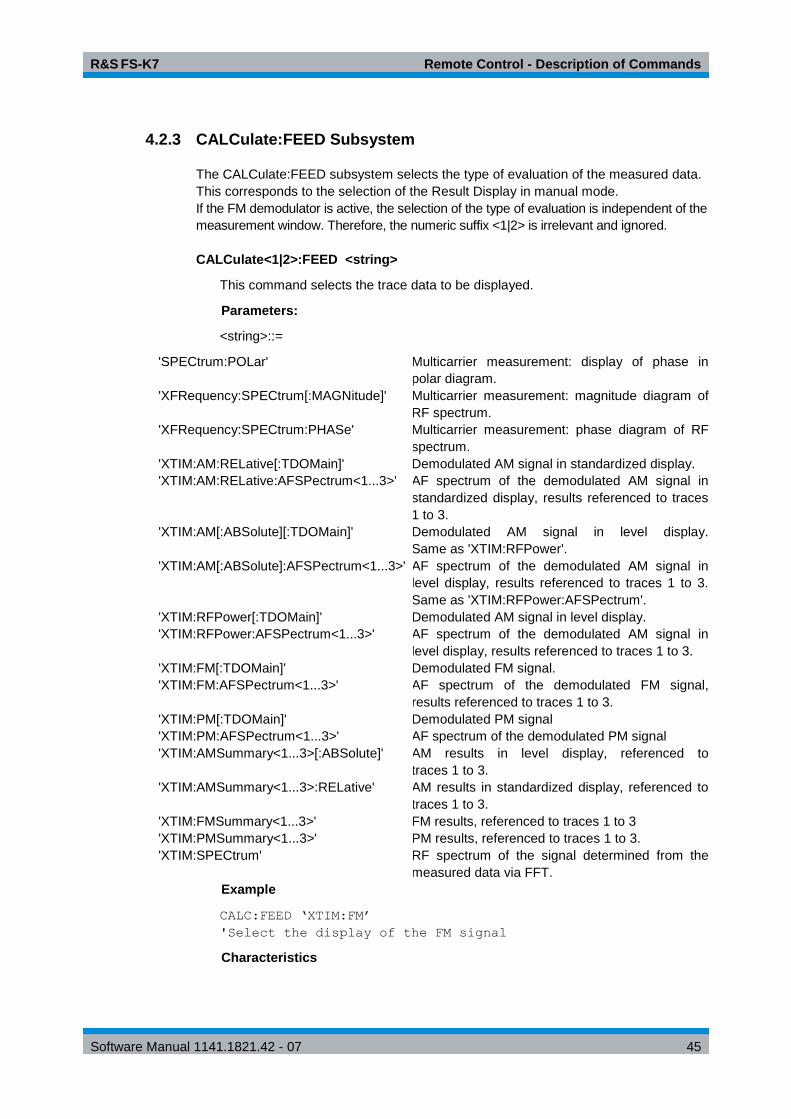
4.2.3 CALCulate:FEED Subsystem
The CALCulate:FEED subsystem selects the type of evaluation of the measured data.
This corresponds to the selection of the Result Display in manual mode.
If the FM demodulator is active, the selection of the type of evaluation is independent of the
measurement window. Therefore, the numeric suffix <1|2> is irrelevant and ignored.
CALCulate<1|2>:FEED <string>
This command selects the trace data to be displayed.
Parameters:
<string>::=
'SPECtrum:POLar' Multicarrier measurement: display of phase in
polar diagram.
'XFRequency:SPECtrum[:MAGNitude]' Multicarrier measurement: magnitude diagram of
RF spectrum.
'XFRequency:SPECtrum:PHASe' Multicarrier measurement: phase diagram of RF
spectrum.
'XTIM:AM:RELative[:TDOMain]' Demodulated AM signal in standardized display.
'XTIM:AM:RELative:AFSPectrum<1...3>' AF spectrum of the demodulated AM signal in
standardized display, results referenced to traces
1 to 3.
'XTIM:AM[:ABSolute][:TDOMain]' Demodulated AM signal in level display.
Same as 'XTIM:RFPower'.
'XTIM:AM[:ABSolute]:AFSPectrum<1...3>' AF spectrum of the demodulated AM signal in
level display, results referenced to traces 1 to 3.
Same as 'XTIM:RFPower:AFSPectrum'.
'XTIM:RFPower[:TDOMain]' Demodulated AM signal in level display.
'XTIM:RFPower:AFSPectrum<1...3>' AF spectrum of the demodulated AM signal in
level display, results referenced to traces 1 to 3.
'XTIM:FM[:TDOMain]' Demodulated FM signal.
'XTIM:FM:AFSPectrum<1...3>' AF spectrum of the demodulated FM signal,
results referenced to traces 1 to 3.
'XTIM:PM[:TDOMain]' Demodulated PM signal
'XTIM:PM:AFSPectrum<1...3>' AF spectrum of the demodulated PM signal
'XTIM:AMSummary<1...3>[:ABSolute]' AM results in level display, referenced to
traces 1 to 3.
'XTIM:AMSummary<1...3>:RELative' AM results in standardized display, referenced to
traces 1 to 3.
'XTIM:FMSummary<1...3>' FM results, referenced to traces 1 to 3
'XTIM:PMSummary<1...3>' PM results, referenced to traces 1 to 3.
'XTIM:SPECtrum' RF spectrum of the signal determined from the
measured data via FFT.
Example
CALC:FEED ‘XTIM:FM’
'Select the display of the FM signal
Characteristics

R&S FS-K7 Remote Control - Description of Commands
Software Manual 1141.1821.42 - 07 46
*RST value: XTIM:FM’
SCPI: conforming
4.2.4 CALCulate:FORMat Subsystem
The CALCulate:FORMat subsystem defines the conversion of measured data.
CALCulate<1|2>:FORMat PHASe | UPHase
This command activates the limitation to 180.
Parameter:
PHASe: Limitation to 180
UPHase: Unwrapped
Example
CALC:FORM PHAS
'Activated the limitation to 180.
Characteristics
*RST value: UPAS
SCPI: conforming
4.2.5 CALCulate:MARKer Subsystem
The CALCulate:MARKer subsystem controls the marker functions in the instrument.
CALCulate<1|2>:MARKer<1...4>:PEXCursion <numeric_value>
This command defines the peak excursion, i.e. the spacing below the trace
maximum which must be attained before a new maximum is recognized, or the
spacing above the trace minimum which must be attained before a new minimum
is recognized. The set value is valid for all markers and delta markers.
The unit of the numerical value depends on the active display.
Example
CALC:MARK:PEXC 10dB
'SPECTRUM display
CALC:MARK:PEXC 100 Hz
'FM DEMOD display
Characteristics
*RST value: 50 kHz (for FM displays)
0.5 RAD (for PM displays)
5 PCT (for standardized AM displays)
6 dB (for level displays)
SCPI: device-specific
The numeric suffix <1...4> in MARKer is irrelevant.

R&S FS-K7 Remote Control - Description of Commands
Software Manual 1141.1821.42 - 07 47
CALCulate<1|2>:MARKer<1...4>:Y?
This command queries the measured value of the selected marker in the selected
measurement window. The corresponding marker is activated before or switched
to marker mode, if necessary.
To obtain a valid query result, a complete sweep with synchronization to the sweep
end must be performed between the activation of the marker and the query of the y
value. This is only possible in single sweep mode.
Example
INIT:CONT OFF
'Switch to single-sweep mode
CALC:MARK2 ON
'Switch on marker 2
INIT;*WAI
'Start a sweep and waits for its end
CALC:MARK2:Y?
'Output the measured value of marker 2.
Characteristics
*RST value: -
SCPI: device-specific
4.2.6 CALCulate:MARKer:FUNCtion:ADEMod Subsystem
The CALCulate:MARKer:FUNCtion:ADEMod subsystem contains the marker functions for the option FM Demodulator R&S FS-K7.
CALCulate<1|2>:MARKer<1...4>:FUNCtion:ADEMod:AFRequency[:RESult<1...3>]?
This command queries the audio frequency with analog demodulation. The
numeric suffix indicates whether trace 1, 2 or 3 is selected.
If several demodulation modes are activated simultaneously with command
SENS:ADEM:FM:TYPE, SENS:ADEM:PM:TYPE, SENS:ADEM:AM:TYPE,
SENS:ADEM:RFP:TYPE, SENS:ADEM:FM:AFSP:TYPE,
SENS:ADEM:PM:AFSP:TYPE, SENS:ADEM:AM:AFSP:TYPE or
SENS:ADEM:RFP:AFSP, the audio frequency of the display mode selected with
CALC:FEED is returned.
Example
ADEM ON
'Switch on FM demodulator
CALC:FEED 'XTIM:AM:TDOM
'Switch on AM result display or

R&S FS-K7 Remote Control - Description of Commands
Software Manual 1141.1821.42 - 07 48
CALC:FEED 'XTIM:FM:TDOM
'Switch on FM result display or
CALC:FEED 'XTIM:RFP:AFSP
'Switch on AF spectrum result
DISP:TRAC ON
'display of the FM and trace or
CALC:FEED 'XTIM:RFP:AFSP
'Switch on AF spectrum result display
DISP:TRAC ON
'of the RF power signal and trace
CALC:MARK:FUNC:ADEM:AFR?
Query audio frequency
Characteristics
*RST value: -
SCPI: device-specific
CALCulate<1|2>:MARKer<1...4>:FUNCtion:ADEMod:AM[:RESult<1...3>]? PPEak|
MPEak| MIDDle| RMS
This command queries the results of the AM modulation measurement. The
numeric suffix (:RESult<1...3>) indicates whether trace 1, 2 or 3 is selected.
PPEak Result of measurement with detector +PK
MPEak Result of measurement with detector -PK
MIDDle Result of averaging PK/2
RMS Result of measurement with detector RMS
Example
ADEM ON
'Switch on FM demodulator
CALC:FEED 'XTIM:AM:REL:TDOM
'Switch on AM result display
DISP:TRAC ON
'Switch on trace
CALC:MARK:FUNC:ADEM:AM? PPE
'Query the peak value
Characteristics
*RST value: -
SCPI: device-specific

R&S FS-K7 Remote Control - Description of Commands
Software Manual 1141.1821.42 - 07 49
CALCulate<1|2>:MARKer<1...4>:FUNCtion:ADEMod:CARRier[:RESult<1...3>]?
This command queries the carrier power.
With the RF power result display, the carrier power is determined from trace 1 to 3
as specified in the numeric suffix. With all other result displays, the carrier power is
determined from the current trace data (CLR/WRITE trace).
Example
ADEM ON
'Switch on FM demodulator
CALC:FEED 'XTIM:RFP
'Switch on RF power result display
CALC:MARK:FUNC:ADEM:CARR?
'Query carrier power
Characteristics
*RST value: -
SCPI: device-specific
CALCulate<1|2>:MARKer<1...4>:FUNCtion:ADEMod:FERRor[:RESult<1...3>]?
This command queries the frequency error with FM and PM demodulation. With
FM demodulation, trace 1 to 3 is selected with the numeric suffix (:RESult<1...3>).
With PM demodulation, the frequency error is determined from the current
measurement data (CLR/WRITE trace).
The mean offset thus determined differs from that calculated in
the[SENSe:]ADEMod:FM:OFFSet? query, since, for determining the frequency
deviation, the modulation is removed by means of lowpass filtering, producing
results that are different from those obtained by averaging with the SENSe:...
command.
This command is available only for traces in the FM and PM result displays. If any
other result display is selected, this command is disabled.
Example
ADEM ON
'Switch on FM demodulator
CALC:FEED 'XTIM:FM:TDO
'Switch on FM result display
CALC:MARK:FUNC:ADEM:FERR?
'Query frequency error of trace 1
Characteristics
*RST value: -
SCPI: device-specific

R&S FS-K7 Remote Control - Description of Commands
Software Manual 1141.1821.42 - 07 50
CALCulate<1|2>:MARKer<1...4>:FUNCtion:ADEMod:FM[:RESult<1...3>]? PPEak |
MPEak | MIDDle | RMS
This command queries the results of FM modulation measurement. The numeric
suffix indicates whether trace 1, 2 or 3 is selected.
PPEak Result of measurement with detector +PK
MPEak Result of measurement with detector -PK
MIDDle Result of averaging PK/2
RMS Result of measurement with detector RMS
Example
ADEM ON
'Switch on FM demodulator
CALC:FEED 'XTIM:AM:REL:TDOM
'Switch on AM result display
DISP:TRAC ON
'Switch on trace
CALC:MARK:FUNC:ADEM:AM? PPE
'Query the peak value
Characteristics
*RST value: -
SCPI: device-specific
CALCulate<1|2>:MARKer<1...4>:FUNCtion:ADEMod:PM[:RESult<1...3>]? PPEak |
MPEak | MIDDle | RMS
This command queries the results of the PM modulation measurement of analog
demodulation. The numeric suffix (:RESult<1...3>) indicates whether trace 1, 2 or 3
is selected.
PPEak Result of measurement with detector +PK
MPEak Result of measurement with detector -PK
MIDDle Result of averaging PK/2
RMS Result of measurement with detector RMS
Example
ADEM ON
'Switch on FM demodulator
CALC:FEED 'XTIM:PM:TDOM
'Switch on PM result display
DISP:TRAC ON
'Switch on trace
CALC:MARK:FUNC:ADEM:PM? PPE
'Query the peak value

R&S FS-K7 Remote Control - Description of Commands
Software Manual 1141.1821.42 - 07 51
Characteristics
*RST value: -
SCPI: device-specific
CALCulate<1|2>:MARKer<1...4>:FUNCtion:ADEMod:SINad:RESult<1...3>?
This command queries the result of the SINAD measurement. The numeric suffix
(:RESult<1...3>) indicates whether trace 1, 2 or 3 is selected.
Example
ADEM ON"
'Switch on FM demodulator
CALC:FEED 'XTIM:RFP:AFSP
'Switch on AF spectrum of FM
DISP:TRAC ON
'Switch on trace
CALC:MARK:FUNC:ADEM:SIN:RES?
'Query SINAD result
Characteristics
*RST value: -
SCPI: device-specific
CALCulate<1|2>:MARKer<1...4>:FUNCtion:ADEMod:THD:RESult<1...3>?
This command queries the result of the THD measurement. The numeric suffix
(:RESult<1...3>) indicates whether trace 1, 2 or 3 is selected.
Example
ADEM ON
'Switch on FM demodulator
CALC:FEED 'XTIM:RFP:AFSP
'Switch on AF spectrum of FM
DISP:TRAC ON
'Switch on trace
CALC:MARK:FUNC:ADEM:THD:RES?
'Query THD result
Characteristics
*RST value: -
SCPI: device-specific

R&S FS-K7 Remote Control - Description of Commands
Software Manual 1141.1821.42 - 07 52
CALCulate<1|2>:MARKer<1 to 4>:FUNCtion:MDEPth:RESult?
This command queries the AM modulation depth in the indicated measurement window.
A complete sweep with synchronization to sweep end must be performed between
switching on the function and querying the measured value to obtain a valid query
result. This is only possible in single sweep mode.
The numeric suffix <1 to 4> of :MARKer is irrelevant for this command.
Example
INIT:CONT OFF
'Switches to single-sweep mode.
CALC:MARK:X 10MHZ
'Sets the reference marker (marker 1) to 'the carrier signal
at 10 MHz.
CALC:MARK:FUNC:MDEP ON
'Switches on the modulation depth 'measurement in screen A.
INIT;*WAI
'Starts a sweep and waits for the end.
CALC:MARK:FUNC:MDEP:RES?
'Outputs the measured value of screen A.
Characteristics
*RST value: -
SCPI: device-specific
This command is only a query and therefore has no *RST value.
CALCulate<1|2>:MARKer<1 to 4>:FUNCtion:MDEPth:[:STATe]
This command switches on the measurement of the AM modulation depth. An AM-
modulated carrier is required on the screen for correct operation. If necessary,
marker 1 is previously activated and set to the largest signal available.
The level value of marker 1 is regarded as the carrier level. On activating the
function, marker 2 and marker 3 are automatically set as delta markers
symmetrically to the carrier to the adjacent maxima of the trace.
If the position of delta marker 2 is changed, delta marker 3 is moved symmetrically
with respect to the reference marker (marker 1). If the position of delta marker 3 is
changed, fine adjustment can be performed independently of delta marker 2.
The analyzer calculates the power at the marker positions from the measured levels.
The AM modulation depth is calculated from the ratio of power values at the
reference marker and the delta markers. If the two AM sidebands differ in power,
the average value of the two power values is used for calculating the AM
modulation depth.
The numeric suffix <1 to 4> of :MARKer is irrelevant with this command.

R&S FS-K7 Remote Control - Description of Commands
Software Manual 1141.1821.42 - 07 53
Example
CALC:MARK:X 10MHZ
'Sets the reference marker (marker 1) to 'the carrier signal
at 10 MHz
CALC:MARK:FUNC:MDEP ON
'Switches on the modulation depth 'measurement in screen A.
CALC:DELT2:X 10KHZ
'Sets delta markers 2 and 3 to the signals 'at 10 kHz from
the carrier signal
CALC:DELT3:X 9.999KHZ
'Corrects the position of delta marker 3 'relative to delta
marker 2.
Characteristics
*RST value: OFF
SCPI: device-specific
4.2.7 CALCulate:UNIT Subsystem
The CALCulate:Unit subsystem defines the units for the parameters that can be set and the measurement results.
CALCulate<1|2>: UNIT:ANGLe DEG | RAD
This command selects the unit for angles.
Example
CALC:UNIT:ANGL DEG"
Characteristics
*RST value: RAD
SCPI: device-specific

R&S FS-K7 Remote Control - Description of Commands
Software Manual 1141.1821.42 - 07 54
4.3 DISPlay Subsystem
The DISPLay subsystem controls the selection and presentation of textual and graphic information as well as of trace data on the display.
DISPlay[:WINDow<1|2>]:TRACe<1...3>:Y[:SCALe]:PDIVision <numeric_value>
This command defines the scaling of the Y-axis in the current unit.
Separate scalings are maintained for the following displays:
- FM display
- PM display
- AM display
- Logarithmic AF spectrum display
The numeric suffix in TRACe<1...3> is irrelevant.
Example
DISP:WIND1:TRAC:Y:PDIV 10KHz
'Set Y scale to '10 kHz/div.
Characteristics
*RST value: 50 kHz (FM display)
2 rad (PM display)
20 PCT (AM display)
10 dB (AF spectrum display)
SCPI: conforming
DISPlay[:WINDow<1|2>]:TRACe<1...3>:Y[:SCALe]:RPOSition 0...100PCT
This command defines the position of the reference value in the selected
measurement window. The numeric suffix in TRACe<1...3> is irrelevant.
Separate reference positions are maintained for the following displays:
- RF power, RF spectrum and AF spectrum of the RF power
- FM, PM and AM
- AF spectrum of the FM, PM and A
Example
DISP:WIND1:TRAC:Y:RPOS 50PCT
Characteristics
*RST value: 100 PCT (level display)
50 PCT (FM, PM or AM display)
100 PCT (AF spectrum display of the FM, PM or AM)
SCPI: conforming

R&S FS-K7 Remote Control - Description of Commands
Software Manual 1141.1821.42 - 07 55
DISPlay[:WINDow<1|2>]:TRACe<1...3>:Y[:SCALe]:RVALue <numeric_value>
This command defines the reference value assigned to the reference position, thus
corresponding to the REFERENCE VALUE parameter in manual control. Separate
reference values are maintained for the various displays.
The numeric suffix in TRACe<1...3> is irrelevant.
Example
DISP:WIND1:TRAC:Y:RVAL 0
'Defines the display value of the reference position at 0 dB
Characteristics
*RST value: 0 Hz
0 rad (PM display)
0 PCT (AM display)
250 kHz (FM AF spectrum display)
10 rad (PM AF spectrum display)
100 PCT (AM AF spectrum display)
SCPI: device-specific
DISPlay[:WINDow<1|2>]:TRACe<1...3>:Y:SPACing LINear | LOGarithmic | LDB
This command switches between linear and logarithmic display in the selected
window. In the case of linear display, it is also possible to switch between unit %
(command DISP:WIND:TRAC:Y:SPAC LIN) and unit dB (command
DISP:WIND:TRAC:Y:SPAC LDB). .
In the case of AF spectrum displays, only the parameters LINear and LOGarithmic
are permitted.
The numeric suffix for TRACe<1...3> is irrelevant.
Example
DISP:WIND1:TRAC:Y:SPAC LIN
Characteristics
*RST value: LOGarithmic
SCPI: conforming

R&S FS-K7 Remote Control - Description of Commands
Software Manual 1141.1821.42 - 07 56
4.4 INSTrument Subsystem
The INSTrument subsystem selects the operating mode of the unit either via text
parameters or fixed numbers.
INSTrument:NSELect 1| 3
This command switches between the operating modes by means of numbers.
Parameter:
1: Spectrum analysis mode
3: FM demodulator mode
Example
INST:NSEL 1
'Switch to SPECTRUM mode
Characteristics
*RST value: 1
SCPI: conforming
INSTrument[:SELect] SANalyzer | ADEMod
This command switches between the operating modes by means of text
parameters.
Parameter:
ADEMod: FM demodulator mode
SANalyzer: Spectrum analysis mode
Example
INST SAN
'Switch to SPECTRUM mode
Characteristics
*RST value: SANalyzer SCPI: conforming
4.5 SENSe Subsystem
The SENSe subsystem is organized in several subsystems. The commands of these
subsystems directly control device-specific settings; they do not refer to the signal
characteristics of the measurement signal.
The SENSe subsystem controls the essential parameters of the analyzer. In
accordance with the SCPI standard, the keyword "SENSe" is optional for this reason,
i.e. it is not necessary to include the SENSe node in command sequences.

R&S FS-K7 Remote Control - Description of Commands
Software Manual 1141.1821.42 - 07 57
4.5.1 [SENSe:]ADEMod Subsystem
The purpose of the commands defined below is to set up the R&S FSP spectrum
analyzer for the measurement of FM, PM and AM modulated signals in a way that
allows to obtain as many measurement results as possible with a single shot
measurement.
For this purpose, the R&S FSP has been equipped with a demodulator that is capable
of performing both FM and AM demodulation at a time. Additionally maximum,
minimum and average or current values can be obtained in parallel over a selected
number of measurements. In order to make it suitable for bursted signals the
demodulator can be configured in terms of pretrigger time, sample rate and record
length.
Demodulation will be performed offline, i.e. on signals previously stored into memory.
The I/Q memory available for this purpose is 2 x 128 k samples. The sampling rate can
be selected in the range from 15.625 to 32 MHz.
The R&S FS-K supports measurement data rates up to 64 MHz, and the option R&S
FS-K-B72 supports rates up to 256 MHz.
Example In the case of a Bluetooth signal, the signal in question is described in the
following diagram:
Frequency versus time:
t
Record Length
Trigger
Signal
Offset
Samples
Measurement results of interest are:
FM offset
FM deviation (maximum and minimum) for signal modulated with ‘1‘ values only.
FM deviation (maximum and minimum) for signal modulated with ‘0‘ values only.
AM modulation depth for positive and negative burst ramp.
These values can be obtained by external computations from the frequency or
amplitude versus time data. For this purpose, the R&S FSP will deliver the following
results:
Demodulated FM signal (current values, averaged, maxhold or minhold selectable)

R&S FS-K7 Remote Control - Description of Commands
Software Manual 1141.1821.42 - 07 58
Demodulated AM signal (current values, averaged, maxhold or minhold
selectable)
FM offset (current value or averaged selectable)
The following settings are required on the R&S FSx:
Types of demodulation to be performed simultaneously (AM/FM)
Sampling rate
Record length
Trigger source (free run/external)
Pretrigger samples
Number of measurements for average/maxhold/minhold
In addition, the required measurement results need to be configured for each type of
demodulation. The R&S FSx can simultaneously determine multiple types of
demodulation with a maximum of 3 different result types. The following result types can
be selected:
WRITe The current measurement results are determined.
AVERage The measurement results are averaged over a specified number of
measurements
MAXHold The maximum result values are determined over a specified number of
measurements
MINHold The minimum result values are determined over a specified number of
measurements
In practice, the commands defined below are used as follows:
The instrument is set first. Then a measurement is started and the result list read in
after synchronization to the end of the measurement. This method permits the control
computer to be used for other tasks while the R&S FSP is performing the
measurement.
Analog demodulation is only available for screen A. Therefore, it is not permissible to
enter "SENSe2..." for the commands of the SENSe:ADEMod subsystem.
[SENSe:]ADEMod:AF:CENTer <numeric_value>
This command sets the center frequency for the display of the AF spectrum.
Example
ADEM ON
'Switch on FM demodulator
CALC:FEED 'XTIM:RFP:AFSP
'Switch on "FM AF spectrum" display
or
CALC:FEED 'XTIM:RFP:AFSP
'Switch on "AF spectrum of the RF power signal" display

R&S FS-K7 Remote Control - Description of Commands
Software Manual 1141.1821.42 - 07 59
ADEM:BAND 5 MHz
'Set meas. bandwidth to 5 MHz
ADEM:AF:CENT 500kHz
'Set AF center frequency to 500 kHz
ADEM:AF:SPAN 200kHz
'Set AF span to 200 kHz
Characteristics
*RST value: 1.25 MHz
SCPI: device-specific
[SENSe:]ADEMod:AF:COUPling AC | DC
This command selects the coupling of the AF path.
Example
ADEM:AF:COUP DC
'Switch on DC coupling.
Characteristics
*RST value: AC
SCPI: device-specific
[SENSe:]ADEMod:AF:SPAN <numeric_value>
This command sets the span for the display of the AF spectrum.
The span is limited to half the measurement bandwidth of analog demodulation
(SENS:ADEM:BAND).
Example
ADEM ON
'Switch on FM demodulator
CALC:FEED 'XTIM:RFP:AFSP'
'Set "FM AF spectrum" display
or
CALC:FEED 'XTIM:RFP:AFSP'
'Switch on "AF spectrum of the RF power signal" display
ADEM:BAND 5 MHz
'Set meas. bandwidth to 5 MHz
ADEM:AF:CENT 500kHz
'Set AF center frequency to 500 kHz
ADEM:AF:SPAN 200kHz
'Set AF span to 200 kHz

R&S FS-K7 Remote Control - Description of Commands
Software Manual 1141.1821.42 - 07 60
Characteristics
*RST value: 2.5 MHz
SCPI: device-specific
[SENSe:]ADEMod:AF:SPAN:FULL
This command sets the maximum span for the display of the AF spectrum.
The maximum span corresponds to half the measurement bandwidth of analog
demodulation (SENS:ADEM:BAND).
Example
ADEM ON
'Switch on FM demodulator
CALC:FEED'XTIM:RFP:AFSP'
'Switch on "FM AF spectrum" display
or
CALC:FEED'XTIM:RFP:AFSP'
'Switch on "AF spectrum of the RF power signal" display
ADEM:BAND 5 MHz
'Set meas. bandwidth to 5 MHz
ADEM:AF:SPAN:FULL
'Set AF span to 2.5 MHz
Characteristics
*RST value: -
SCPI: device-specific
[SENSe:]ADEMod:AF:STARt <numeric_value>
This command sets the start frequency for the display of the AF spectrum.
Example
ADEM ON
'Switch on FM demodulator
CALC:FEED 'XTIM:RFP:AFSP'
'Switch on "FM AF spectrum" display
or
CALC:FEED 'XTIM:RFP:AFSP'
'Switch on "AF spectrum of the RF power signal" display
ADEM:BAND 5 MHz
'Set meas. bandwidth to 5 MHz
ADEM:AF:STAR 0kHz
'Set AF start frequency to 0 kHz

R&S FS-K7 Remote Control - Description of Commands
Software Manual 1141.1821.42 - 07 61
ADEM:AF:STOP 500kHz
'Set AF stop frequency to 500 kHz
Characteristics
*RST value: 0 MHz
SCPI: device-specific
[SENSe:]ADEMod:AF:STOP <numeric_value>
This command sets the stop frequency for the display of the AF spectrum.
The stop frequency is limited to half the measurement bandwidth of analog
demodulation (SENS:ADEM:BAND).
Example
ADEM ON
'Switch on FM demodulator
CALC:FEED 'XTIM:RFP:AFSP'
'Switch on "FM AF spectrum" display
or
CALC:FEED 'XTIM:RFP:AFSP'
'Switch on "AF spectrum of the RF power signal" display
ADEM:BAND 5 MHz
'Set meas. bandwidth to 5 MHz
ADEM:AF:STAR 0kHz
'Set AF start frequency to 0 kHz
ADEM:AF:STOP 500kHz
'Set AF stop frequency to 500 kHz
Characteristics
*RST value: 2.5 MHz
SCPI: device-specific

R&S FS-K7 Remote Control - Description of Commands
Software Manual 1141.1821.42 - 07 62
[SENSe:]ADEMod:BANDwidth | BWIDth:DEModulation <numeric_value>
This command defines the demodulation bandwidth for analog demodulation.
Depending on the selected demodulation bandwidth, the instrument selects the
required sampling rate. The available values of the demodulation bandwidths are
defined by the sampling rates.
Demodulation
bandwidth
Sampling rate Comment
120 MHz 256 MHz with R&S FSQ-B72 only
50 MHz/85 MHz (1)
128 MHz with R&S FSQ-B72 only
30 MHz 64 MHz with R&S FSQ only
18 MHz 32 MHz with R&S FSQ only
10 MHz 32 MHz
8 MHz 16 MHz This restriction only applies to R&S FSP and
R&S FSU without B72:
This filter is only flat for about 6 MHz, it has a
3dB decay at 7 MHz.
5 MHz 8 MHz
3 MHz 4 MHz
1,6 MHz 2 MHz
800 kHz 1 MHz
400 kHz 500 kHz
200 kHz 250 kHz
100 kHz 125 kHz
50 kHz 62.5 kHz
25 kHz 31.25 kHz
12.5 kHz 15.625 kHz
6.4 kHz 7.8125 kHz
3.2 kHz 3.90625 kHz
1.6 kHz 1.953125 kHz
800 Hz 976.5625 Hz
400 Hz 488.28125 Hz
200 Hz 244.140625 Hz
100 Hz 122.0703125 Hz
(1) The demodulation bandwidth at a sampling rate of 128 MHz depends on the center frequency that has been set. At a center frequency of =3.6 GHz, the demodulation bandwidth is 50 MHz; at higher center frequencies, it is 85 MHz.
Example
ADEM:BAND:DEM 1MHz
'Set test bandwidth to 1 MHz.

R&S FS-K7 Remote Control - Description of Commands
Software Manual 1141.1821.42 - 07 63
Characteristics
*RST value: 5 MHz
SCPI: device-specific
[SENSe:]ADEMod:MTIMe <numeric_value>
This command sets the measuring time for the analog demodulation.
Example
ADEM:MTIM 62. 5us
'Set measurement time to 62.5 s.
Characteristics
*RST value: 62. 5us
SCPI: device-specific
[SENSe1]:ADEMod:MTIMe:AUTO ON|OFF
This command activates/deactivates the automatic measurement time of the
multicarrier measurement.
Example
SENS1:ADEM ON
‘Switch on Ademod measurement.
SENS1:ADEM:MCPH:STAT ON
‘Multicarrier measurement on.
SENS1:ADEM: MTIM:AUTO OFF
'Set measurement time to manual setzen.
Characteristics
*RST value: OFF
SCPI: device-specific
[SENSe:]ADEMod:RLENgth?
This command returns the currently set record length for the analog demodulation.
Example
ADEM:RLEN?
'Return the current record length.
Characteristic:
*RST value: -
SCPI:device-specific

R&S FS-K7 Remote Control - Description of Commands
Software Manual 1141.1821.42 - 07 64
[SENSe:]ADEMod:SET <sample rate>,<record length>,<trigger source>,<trigger
slope>,<offset samples>,<# of meas>
This command configures the FM demodulator of the R&S FSP.
Parameter:
<sample rate>: Frequency at which measured values are taken from the A/D
converter and stored in I/Q memory.
Value range: 122.0703125 Hz, 244.140625 Hz, 488.28125 Hz,
976.5625 Hz, 1.953125 kHz, 3.90625 kHz, 7.8125
kHz, 15.625 kHz, 31.25 kHz, 62.5 kHz, 125 kHz,
250 kHz, 500 kHz, 1 MHz, 2 MHz, 4 MHz, 8 MHz,
16 MHz, 32 MHz
<record length>: Number of samples to be stored in I/Q memory.
Value range: 1 to 130560 (128 * 1024 - 512)
<trigger source>: Selection of the trigger source for the demodulator.
Valid values: IMMediate | EXTernal IFPower | FM | AM |
AMRelative | PM
<trigger slope>: Trigger slope selected.
Valid values: POSitive | NEGative
The value indicated here will be ignored for <trigger source> =
IMMediate.
<offset samples>: Number of samples to be used as an offset to the trigger signal.
Value range: -65024 to 130560 (= -64 * 1024 + 512 to 128 *
1024 - 512)
The indicated value is ignored for <trigger source> = IMMediate
<# of meas>: Number of measurements. The value indicated here is particularly
necessary for the AVERage/MAXHold/MINHold function.
Value range: 0 to 32767
Example
ADEM:SET 8MHz,32000,EXT,POS,-500,30
'Will perform a measurement with the following settings:
sample rate = 8 MHz
record length = 32000
trigger source = EXTernal
trigger slope = POSitive
offset samples = -500 (= 500 samples before trigger occurs )
# of meas = 30

R&S FS-K7 Remote Control - Description of Commands
Software Manual 1141.1821.42 - 07 65
Characteristics
*RST values: sample rate = 8 MHz
record length = 501
trigger source = IMMediate
trigger slope = POSitive
offset samples = 0
# of meas = 0
SCPI: device-specific
[SENSe:]ADEMod:SRATe?
This command returns the currently set sampling rate for the analog demodulation.
Example
ADEM:SRAT?
'Return the current sampling rate.
Characteristics
*RST value: -
SCPI: device-specific
[SENSe:]ADEMod[:STATe] ON | OFF
This command switches on the FM demodulator of the instrument. The instrument
will be set to time-domain measurement (span = 0) at the current center frequency.
Note:
The measurement is always performed in screen A. Split-screen operation will be
switched off as soon as the demodulator is activated.
Example
ADEM ON
'Switch on the FM demodulator
Characteristics
*RST value: OFF
SCPI: device-specific
[SENSe:]ADEMod:ZOOM:STARt 0 s to measurement time
This command selects the start time for displaying the individual measurement
values of the FM demodulator. The maximum value depends on the measurement
time set in the instrument; this value can be queried with ADEM:ZOOM:START?
MAX.
If the zoom function has been switched on, 501 (R&S FSP) or 625 (R&S FSU and
R&S FSQ) measurement points will be displayed starting at the time that has been
set.

R&S FS-K7 Remote Control - Description of Commands
Software Manual 1141.1821.42 - 07 66
Example
ADEM:ZOOM ON
'Switch on zoom function
ADEM:ZOOM:STAR 500us
'Set display starting point to 500 s
Characteristics
*RST value: 0 s
SCPI: device-specific
[SENSe:]ADEMod:ZOOM[:STATe>] ON | OFF
This command switches the zoom function for the measurement data of the FM
demodulator on or off. Depending on the selected measurement time and
demodulation bandwidth, more measurement points are captured than can be
shown on the display.
If the zoom function has been switched on, exactly 501 (R&S FSP) or 625 (R&S
FSU and R&S FSQ) measurement points from the measured value memory will be
shown starting at the time defined with [SENS:]ADEM:ZOOM:STARt.
If the zoom function has been switched off, all measurement points will be compressed
down to the number of points available on the display by means of data reduction.
Example
ADEM:ZOOM ON
'Switch on the zoom function.
Characteristics
*RST value: OFF
SCPI: device-specific
4.5.2 [SENSe:]ADEMod:AM Subsystem
[SENSe:]ADEMod:AM[:ABSolute]:AFSPectrum:RESult? <result type>
This command reads out the result data of the AF spectrum of the RF signal in the
time domain for the specified result type. The format of the output data is defined
using the FORMat command.
Note:
Traces cannot be queried when VIEW is active.
Parameters
<result type>: WRITe The current measured values are returned.
AVERage The measurement results averaged over the
specified number of measurements are returned.
MAXHold The maximum result over the specified number of
measurements is returned.
MINHold The minimum result over the specified number of
measurements is returned.

R&S FS-K7 Remote Control - Description of Commands
Software Manual 1141.1821.42 - 07 67
Note:
The specified result type must be one that was configured with the command
[SENSe:] ADEMod:AM[:ABSolute]:AFSPectrum[:TYPE]. Otherwise, a query error
will be generated.
Return values:
ASCII format (FORMat ASCII):
In this case, the command will return a list of comma-separated values (CSV) of
the measured values in floating point format. The output unit is dBm (logarithmic
display) or V (linear display).
Binary format (FORMat REAL,32):
In this case, the command will return binary data (Definite Length Block Data
according to IEEE 488.2), with each measured value formatted in 32-bit IEEE 754
floating point format. The response string will have the following structure:
#41024<value1><value2>...<value n>
where
#4 Number of digits in the following number of data bytes (= 4 in the
Example)
1024 Number of following data bytes (# of DataBytes = 1024 in the
Example)
<value x> 4-byte floating point value
Examples:
ADEM:SET 8MHz,32000,EXT,POS,-500,30
'Set demodulator
ADEM:FM AVER,MAXH,MINH
'Select FM results to be measured
ADEM:AM WRIT,OFF,OFF
'Select results of the RF signal to be 'measured in the time
domain
ADEM:AM:AFSP FSP WRIT,OFF,OFF
'Select the AF spectrum results of the 'RF signal to be
measured in the time 'domain
ADEM ON
'Switch on demodulator
INIT;*WAI
'Start measurement and wait for end
FORM ASC
'Select output format
ADEM:FM:RES? AVER
'Read FM average value result data
ADEM:FM:RES? MAXH
'Read FM MAXHold result data

R&S FS-K7 Remote Control - Description of Commands
Software Manual 1141.1821.42 - 07 68
ADEM:FM:RES? MINH
'Read FM MINHold result data
ADEM:AM:RES? WRIT
'Read current AM result data
ADEM:AM:AFSP:RES? WRIT
'Read current AF spectrum resul 'data of the RF signal in the
time domain
Characteristics
*RST value: -
SCPI: device-specific
[SENSe:]ADEMod:AM[:ABSolute]:AFSPectrum[:TYPE] <result type 1>,<result
type 2>,<result type 3>
This command selects the AF spectrum result types of the RF signal in the time
domain to be measured simultaneously.
Parameters
<result type 1/2/3>: WRITe The current measured values are recorded.
AVERage The measurement results are averaged over
the specified number of measurements.
MAXHold The maximum result over the specified
number of measurements is determined.
MINHold The minimum result over the specified number
of measurements is determined.
VIEW The measurement result is frozen on the
display, i.e. it is not recalculated in further
measurements.
OFF The result type is not used.
Settings different from OFF can be assigned to only one result type at a time.
Together with other signals, a maximum of six traces can be activated simultaneously.
For example, three FM and three PM result types can be activated simultaneously.
If all result types are set to OFF, no AF spectrum of the RF signal in the time domain
will be calculated.
The result type AF spectrum of the RF signal in the time domain cannot be activated
simultaneously with other AF spectra.
Examples:
ADEM:AM:AFSP FSP AVER,MAXH,MINH
'Determine average, maximum and minimum simultaneously
ADEM:AM:AFSP FSP WRIT,OFF,OFF
'Determine only the current measurement results
ADEM:AM:AFSP OFF,OFF,OFF
'Switch off calculation of the AF spectrum

R&S FS-K7 Remote Control - Description of Commands
Software Manual 1141.1821.42 - 07 69
Characteristics
*RST values: OFF,OFF,OFF
SCPI: device-specific
[SENSe:]ADEMod:AM[:ABSolute][:TDOMain]:RESult? <result type>
This command reads the result data obtained by AM demodulation depending on
the type indicated as a parameter. The data format of the output data is defined by
the FORMat command.
Note:
Traces cannot be queried when VIEW is active.
Parameters:
<result type>: WRITe The current measured values are recorded.
AVERage The measurement results averaged over the
specified number of measurements are obtained.
MAXHold The maximum result is determined over the
specified number of measurements.
MINHold The minimum result is determined over the
specified number of measurements.
Note:
The result type indicated must be one that was configured with the command
[SENSe:]ADEMod:AM[:ABSolute][:TDOMain] [:TYPE]. Otherwise, a query error will
be generated.
Return values:
ASCII format (FORMat ASCII):
In this case, the command will return a list of comma-separated values (CSV) of
the measured values in floating point format. The output unit is dBm (logarithmic
display) or V (linear display).
Binary format (FORMat REAL,32):
In this case, the command will return binary data (Definite Length Block Data
according to IEEE 488.2), with each measured value formatted in 32-bit IEEE 754
floating point format. The response string will have the following structure:
#41024<value1><value2>...<value n>
with
#4 Number of digits in the following number of data bytes (= 4 in the
Example)
1024 Number of following data bytes (# of DataBytes, = 1024 in the
Example)
<value x> 4-byte floating point value

R&S FS-K7 Remote Control - Description of Commands
Software Manual 1141.1821.42 - 07 70
Examples:
ADEM:SET 8MHz,32000,EXT,POS,-500,30
'Set up demodulator parameters
ADEM:FAM AVER,MAXH,MINH
'Select results to measure
ADEM ON
'Switch on demodulator
INIT;*WAI
'Start measurement and wait for end
FORM ASC
'Select output format
ADEM:FM:RES? AVER
'Read average results
ADEM:FM:RES? MAXH
'Read MAXHold results
ADEM:FM:RES? MINH
'Read MINHold results
Characteristics
*RST value: -
SCPI: device-specific
[SENSe:]ADEMod:AM:RELative:AFSPectrum:RESult? <result type>
This command reads out the result data of the AF spectrum of the AM-
demodulated signal for the specified result type. The format of the output data is
defined using the FORMat command.
Note:
Traces cannot be queried when VIEW is active.
Parameter:
<result type>: WRITe The current measured values are returned.
AVERage The measurement results averaged over the
specified number of measurements are returned.
MAXHold The maximum result over the specified number of
measurements is returned.
MINHold The minimum result over the specified number of
measurements is returned.
Note:
The specified result type must be one that was configured with the command
[SENSe:]ADEMod:AM:RELative:AFSPectrum[:TYPE]. Otherwise, a query error
will be generated.

R&S FS-K7 Remote Control - Description of Commands
Software Manual 1141.1821.42 - 07 71
Return values:
ASCII format (FORMat ASCII):
In this case, the command will return a list of comma-separated values (CSV) of
the measured values in floating point format. The output unit is dBm (logarithmic
display) or % (linear display).
Binary format (FORMat REAL,32):
In this case, the command will return binary data (Definite Length Block Data
according to IEEE 488.2), with each measured value formatted in 32-bit IEEE 754
floating point format. The response string will have the following structure:
#41024<value1><value2>...<value n>
Where
#4 Number of digits in the following number of data bytes (= 4 in the
Example)
1024 Number of following data bytes (# of DataBytes = 1024 in the Example)
<value x> 4-byte floating point value
Examples:
ADEM:SET 8MHz,32000,EXT,POS,-500,30
'Set demodulator
ADEM:FM AVER,MAXH,MINH
'Select the FM results to be measured
ADEM:AM:REL WRIT,OFF,OFF
'Select the AM results to be
'measured
ADEM:AM:REL:AFSP WRIT,OFF,OFF
'Select the AF spectrum results of the 'demodulated AM signal
to be measured
ADEM ON
'Switch on demodulator
INIT;*WAI
'Start measurement and wait for end
FORM ASC
'Select output format
ADEM:FM:RES? AVER
'Read FM average value result data
ADEM:FM:RES? MAXH
'Read FM MAXHold result data
ADEM:FM:RES? MINH
'Read FM MINHold result data
ADEM:AM:REL:RES? WRIT
'Read current AM result data
ADEM:AM:REL:AFSP:RES? WRIT
'Read current AF spectrum result data of the demodulated AM

R&S FS-K7 Remote Control - Description of Commands
Software Manual 1141.1821.42 - 07 72
signal
Characteristics
*RST value: -
SCPI: device-specific
[SENSe:]ADEMod:AM:RELative:AFSPectrum[:TYPE] <result type 1>,<result type
2>,<result type 3>
This command selects the AF spectrum result types of the AM-demodulated signal
to be measured simultaneously.
Parameter:
<result type 1/2/3>: WRITe The current measured values are recorded.
AVERage The measurement results are averaged over
the specified number of measurements.
MAXHold The maximum result over the specified
number of measurements is determined.
MINHold The minimum result over the specified
number of measurements is determined.
VIEW The measurement result is frozen on the
display, i.e. it is not recalculated in further
measurements.
OFF The result type is not used.
a.
Settings different from OFF can be assigned to only one result type at a time.
Together with other signals, a maximum of six traces can be activated simultaneously.
For example, three FM and three PM result types can be activated simultaneously.
If all result types are set to OFF, no AF spectrum of the AM-demodulated signal will be
calculated.
The result type AF spectrum of the AM-demodulated signal cannot be activated
simultaneously with other AF spectra.
Examples:
ADEM:AM:REL:AFSP AVER,MAXH,MINH
'Determine average, maximum and minimum value simultaneously
ADEM:AM:REL:AFSP WRIT,OFF,OFF
'Determine only the current measured values
ADEM:AM:REL:AFSP OFF,OFF,OFF
'Switch off calculation of the AF spectrum
Characteristics
*RST values: OFF,OFF,OFF
SCPI: device-specific

R&S FS-K7 Remote Control - Description of Commands
Software Manual 1141.1821.42 - 07 73
[SENSe:]ADEMod:AM:RELative[:TDOMain]:RESult? <result type>
This command reads out the result data of the AM demodulation for the specified
result type. The format of the output data is defined using the FORMat command.
Note:
Traces cannot be queried when VIEW is active.
<result type>: WRITe The current measured values are returned.
AVERage The measurement results averaged over the
specified number of measurements are returned.
MAXHold The maximum result over the specified number of
measurements is returned.
MINHold The minimum result over the specified number of
measurements is returned.
Note:
The specified result type must be one that was configured with the command
[SENSe:]ADEMod:AM:RELative[:TDOMain][:TYPE]. Otherwise, a query error will
be generated.
Return values:
ASCII format (FORMat ASCII):
In this case, the command will return a list of comma-separated values (CSV) of
the measured values in floating point format. The output unit is %.
Binary format (FORMat REAL,32):
In this case, the command will return binary data (Definite Length Block Data
according to IEEE 488.2), with each measured value formatted in 32-bit IEEE 754
floating point format. The response string will have the following structure:
#41024<value1><value2>...<value n>
where
#4 Number of digits in the following number of data bytes (= 4 in the
Example)
1024 Number of following data bytes (# of DataBytes = 1024 in the
Example)
<value x> 4-byte floating point value
Examples:
ADEM:SET 8MHz,32000,EXT,POS,-500,30
'Set demodulator
ADEM:FM AVER,MAXH,MINH
'Select FM results to be measured
ADEM:AM:REL WRIT,OFF,OFF
'Select AM results to be measured
ADEM ON
'Switch on demodulator
R&S FS-K7 Remote Control - Description of Commands
Software Manual 1141.1821.42 - 07 74
INIT;*WAI
'Start measurement and wait for end
FORM ASC
'Select output format
ADEM:FM:RES? AVER
'Read FM average result data
ADEM:FM:RES? MAXH
'Read FM MAXHold result data
ADEM:FM:RES? MINH
'Read FM MINHold result data
ADEM:AM:REL:RES? WRIT
'Read current AM result data
Characteristics
*RST value: -
SCPI: device-specific
[SENSe:]ADEMod:AM:RELative[:TDOMain][:TYPE] <result type 1>,<result type
2>,<result type 3>
This command selects the result types to be measured simultaneously in the case
of AM demodulation.
Parameter:
<result type 1/2/3>: WRITe The current measured values are recorded.
AVERage The measurement results are averaged over
the specified number of measurements.
MAXHold The maximum result over the specified
number of measurements is determined.
MINHold The minimum result over the specified
number of measurements is determined.
VIEW The measurement result is frozen on the
display, i.e. it is not recalculated in further
measurements.
OFF The result type is not used.
b.
Settings different from OFF can be assigned to only one result type at a time.
Together with other signals, a maximum of six traces can be activated
simultaneously. For example, three FM and three PM result types can be activated
simultaneously
If all result types are set to OFF, the AM demodulator will be switched off.
Examples:
ADEM:AM:REL AVER,MAXH,MIN
'Determine average, maximum and minimum value simultaneously

R&S FS-K7 Remote Control - Description of Commands
Software Manual 1141.1821.42 - 07 75
ADEM:AM:REL WRIT,OFF,OFF
'Determine only the current measured values
ADEM:AM:REL OFF,OFF,OFF
'Switch off the AM demodulator
Characteristics
*RST values: WRITe,OFF,OFF
SCPI: device-specific
4.5.3 [SENSe:]ADEMod:FM Subsystem
[SENSe:]ADEMod:FM:AFSPectrum:RESult? <result type>
This command reads out the result data of the AF spectrum of the FM-
demodulated signal for the specified result type. The format of the output data is
defined using the FORMat command.
Note:
Traces cannot be queried when VIEW is active.
Parameter:
<result type>: WRITe The current measured values are returned.
AVERage The measurement results averaged over the
specified number of measurements are returned.
MAXHold The maximum result over the specified number of
measurements is returned.
MINHold The minimum result over the specified number of
measurements is returned.
Note:
The specified result type must be one that was configured with the command
[SENSe:]ADEMod:FM:AFSPectrum[:TYPE]. Otherwise, a query error will be
generated.
Return values:
ASCII format (FORMat ASCII):
In this case, the command will return a list of comma-separated values (CSV) of
the measured values in floating point format. The output unit is dBm (logarithmic
display) or V (linear display).
Binary format (FORMat REAL,32):
In this case, the command will return binary data (Definite Length Block Data
according to IEEE 488.2), with each measured value formatted in 32-bit IEEE 754
floating point format. The response string will have the following structure:
#41024<value1><value2>...<value n>
where
#4 Number of digits in the following number of data bytes (= 4 in the
R&S FS-K7 Remote Control - Description of Commands
Software Manual 1141.1821.42 - 07 76
Example)
1024 Number of following data bytes (# of DataBytes = 1024 in the
Example)
<value x> 4-byte floating point value
Examples:
ADEM:SET 8MHz,32000,EXT,POS,-500,30
'Set demodulator
ADEM:FM AVER,MAXH,MINH
'Select FM results to be measured
ADEM:AM:REL WRIT,OFF,OFF
'Select AM results to be measured
ADEM:FM:AFSP WRIT,OFF,OFF
'Select AF spectrum results of the 'demodulated FM signal to
be 'measured
ADEM ON
'Switch on demodulator
INIT;*WAI
'Start measurement and wait for end
FORM ASC
'Select output format
ADEM:FM:RES? AVER
'Read FM average result data
ADEM:FM:RES? MAXH
'Read FM MAXHold result data
ADEM:FM:RES? MINH
'Read FM MINHold result data
ADEM:AM:RES? WRIT
'Read current AM result data
ADEM:FM:AFSP:RES? WRIT
'Read current AF spectrum result data 'of the demodulated FM
signal
Characteristics
*RST value: -
SCPI: device-specific
[SENSe:]ADEMod:FM:AFSPectrum[:TYPE] <result type 1>,<result type 2>,<result
type 3>
This command selects the AF spectrum result types of the FM-demodulated signal
to be measured simultaneously.
Parameter:
<result type 1/2/3>: WRITe The current measured values are recorded.
AVERage The measurement results are averaged

R&S FS-K7 Remote Control - Description of Commands
Software Manual 1141.1821.42 - 07 77
over the specified number of
measurements.
MAXHold The maximum result over the specified
number of measurements is determined.
MINHold The minimum result over the specified
number of measurements is determined.
VIEW The measurement result is frozen on the
display, i.e. it is not recalculated in further
measurements.
OFF The result type is not used.
Settings different from OFF can be assigned to only one result type at a time.
Together with other signals, a maximum of six traces can be activated simultaneously.
For example, three FM and three PM result types can be activated simultaneously.
If all result types are set to OFF, no AF spectrum of the FM-demodulated signal will be
calculated.
The result type AF spectrum of the FM-demodulated signal cannot be activated
simultaneously with other AF spectra.
Examples:
ADEM:FM:AFSP AVER,MAXH,MINH
'Determine average, maximum and minimum value simultaneously
ADEM:FM:AFSP WRIT,OFF,OFF
'Determine only the current measured values
ADEM:FM:AFSP OFF,OFF,OFF
'Switch off calculation of the AF spectrum
Characteristics
*RST values: OFF,OFF,OFF
SCPI: device-specific
[SENSe:]ADEMod:FM:OFFSet? <result type>
This command calculates the FM offset of the current measured data set.
If averaging has been activated prior to data acquisition (using the command
[SENSe:]ADEMod:FM [:TYPE]), the average FM offset can also be obtained by
setting <result type> = AVERage. The average FM offset obtained in this way
differs from the one calculated by CALC:MARK:FUNC:ADEM:FERR?, since, for
determination of the frequency deviation, the modulation is removed by means of
lowpass filtering, producing results that are different from those obtained by
averaging.
Parameters:
<result type>: IMMediate The current measurement results are used for
calculating the FM offset.
AVERage The measurement results averaged over the

R&S FS-K7 Remote Control - Description of Commands
Software Manual 1141.1821.42 - 07 78
specified number of measurements are used for
calculation of the FM offset.
Note:
If no average measurement has been active during the last measurement
sequence, only the command [SENSe:]ADEMod:FM:OFFSet? IMMediate will
return a valid result (data to calculate the FM offset are taken from the last
measured data set).
[SENSe:]ADEMod:FM:OFFSet? AVERage will cause a query error in this case.
Example
ADEM:SET 8MHz,32000,EXT,POS,-500,30
'Set demodulator to perform '30 measurements
ADEM:FM AVER,OFF,OFF
'Set FM results to perform
'averaging
ADEM:AM OFF,OFF,OFF
'Switch off AM demodulation
ADEM ON
'Switch on FM demodulator
INIT;*WAI
'Start measurement and wait 'for end
ADEM:FM:OFFS? IMM
'Read FM offset of last measurement of the sequence 'of 30
ADEM:FM:OFFS? AVER
'Read FM offset averaged over 30 measurements
Characteristics
*RST value: -
SCPI: device-specific
[SENSe:]ADEMod:FM[:TDOMain]:RESult? <result type>
This command reads the result data obtained by FM demodulation depending on
the type indicated as a parameter. The data format of the output data is defined by
the FORMat command.
Note:
Traces cannot be queried when VIEW is active.
Parameter:
<result type>: WRITe The current trace data is recorded.
AVERage The measurement results averaged over the
specified number of measurements are obtained.
MAXHold The maximum result is determined over the specified
number of measurements.
MINHold The minimum result is determined over the specified
number of measurements.
R&S FS-K7 Remote Control - Description of Commands
Software Manual 1141.1821.42 - 07 79
Note:
The specified result type must be one that was configured with the command
[SENSe:]ADEMod:FM[:TYPE]. Otherwise, a query error will be generated.
Return values:
ASCII format (FORMat ASCII):
In this case, the command will return a list of comma-separated values (CSV) of
the measured values in floating point format. The output unit is Hz.
Binary format (FORMat REAL,32):
In this case, the command will return binary data (Definite Length Block Data
according to IEEE 488.2), with each measured value formatted in 32-bit IEEE 754
floating point format. The response string will have the following structure:
#41024<value1><value2>...<value n>
with
#4 Number of digits (= 4 in the Example) of the following number of data
bytes
1024 Number of following data bytes (# of DataBytes = 1024 in the
Example)
<value x> 4-byte floating point value
Examples:
ADEM:SET 8MHz,32000,EXT,POS,-500,30
'Set demodulator 'parameters
ADEM:FM AVER,MAXH,MINH
'Select FM results to measure
ADEM:AM WRIT,OFF,OFF
'Select AM results to measure
ADEM ON
'Switch on demodulator
INIT;*WAI
'Start measurement and wait 'for end
FORM ASC
'Select output format
ADEM:FM:RES? AVER
'Read FM average results
ADEM:FM:RES? MAXH
'Read FM MAXHold results
ADEM:FM:RES? MINH
'Read FM MINHold result data
ADEM:AM:RES? WRIT
'Read current AM results

R&S FS-K7 Remote Control - Description of Commands
Software Manual 1141.1821.42 - 07 80
Characteristics
*RST value: -
SCPI: device-specific
[SENSe:]ADEMod:FM[:TDOMain][:TYPE] <result type 1>,<result type
2>,<result type 3>
This command selects the result types to be created in parallel by FM
demodulation.
Parameters:
<result type 1/2/3>: WRITe The current measured values are recorded.
AVERage The measurement results are averaged over the
specified number of measurements.
MAXHold The maximum result is determined over the
specified number of measurements.
MINHold The minimum result is determined over the
specified number of measurements.
VIEW The measurement result is frozen on the display,
i.e. it is not recalculated in further
measurements.
OFF The result type is not used.
Note:
Settings different from OFF can be assigned to only one result type at a time.
Together with other signals, a maximum of six traces can be activated
simultaneously. For example, three FM and three PM result types can be activated
simultaneously.
The FM demodulator is deactivated by setting all result types to OFF.
Examples:
ADEM:FM AVER,MAXH,MINH
'Determine average, maximum and minimum value simultaneously
ADEM:FM WRIT,OFF,OFF
'Determine only the current measurement result
ADEM:FM OFF,OFF,OFF
'Switch off the FM demodulator
Characteristics
*RST values: WRITe,OFF,OFF
SCPI: device-specific

R&S FS-K7 Remote Control - Description of Commands
Software Manual 1141.1821.42 - 07 81
4.5.4 [SENSe:]ADEMod:MCPHase Subsystem
[SENSe1]:ADEMod:MCPHase:METHod ORTHogonal|FLATtop
The command selects the method for the multicarrier measurement.
Example
SENS1:ADEM ON
'Switch on Ademod measurementSENS1:ADEM:MCPH:STAT ON
'Multicarrier measurement on.
SENS1:ADEM:MCPH:METH ORTHl
'Select method.
Characteristics
*RST value: ORTH
SCPI: device-specific
[SENSe1]:ADEMod:MCPHase:POLar:RESult?
Multicarrier measurement: query of polar trace irrespective of selected diagram,
Returns list with magnitude/phase pairs.
Example
SENS1:ADEM ON
'Switch on Ademod measurement
SENS1:ADEM:MCPH:STAT ON
'Multicarrier measurement on..
SENS1:ADEM:MCPH:POL:RESult?
'Trace query
Characteristics
*RST value: -
SCPI: device-specific
[SENSe1]:ADEMod:MCPHase:SPACing <numeric_value>
The command enters the carrier spacing of the multicarrier measurement.
Example
SENS1:ADEM ON
'Switch on Ademod measurement
SENS1:ADEM:MCPH:STAT ON
'Multicarrier measurement on.
SENS1:ADEM:MCPH: SPAC 100KHZ
'Enter spacing.

R&S FS-K7 Remote Control - Description of Commands
Software Manual 1141.1821.42 - 07 82
Characteristics
*RST value: -
SCPI: device-specific
[SENSe1]:ADEMod:MCPHase:STATe ON|OFF
The command activates/deactivates the multicarrier phase measurement.
Example
SENS1:ADEM ON
'Switch on Ademod measurement
SENS1:ADEM:MCPH:STAT ON
'Multicarrier measurement on
Characteristics
*RST value: OFF
SCPI: device-specific
4.5.5 [SENSe:]ADEMod:PM Subsystem
[SENSe:]ADEMod:PM:AFSPectrum:RESult? <result type>
This command reads out the result data of the AF spectrum of the PM-
demodulated signal for the specified result type. The format of the output data is
defined using the FORMat command.
Note:
Traces cannot be queried when VIEW is active.
Parameter:
<result type>: WRITe The current measured values are returned.
AVERage The measurement results averaged over the specified
number of measurements are returned.
MAXHold The maximum result over the specified number of
measurements is returned.
MINHold The minimum result over the specified number of
measurements is returned.
Note:
The specified result type must be one that was configured with the command
[SENSe:]ADEMod:PM:AFSPectrum[:TYPE]. Otherwise, a query error will be
generated.
Return values:
ASCII format (FORMat ASCII):
In this case, the command will return a list of comma-separated values (CSV) of
the measured values in floating point format. The output unit is dB (logarithmic
display) or depends on the unit selected - either RAD or DEG (linear display).

R&S FS-K7 Remote Control - Description of Commands
Software Manual 1141.1821.42 - 07 83
Binary format (FORMat REAL,32):
In this case, the command will return binary data (Definite Length Block Data
according to IEEE 488.2), with each measured value formatted in 32-bit IEEE 754
floating point format. The response string will have the following structure:
#41024<value1><value2>...<value n>
where
#4 Number of digits in the following number of data bytes (= 4 in the
Example)
1024 Number of following data bytes (# of DataBytes = 1024 in the
Example)
<value x> 4-byte floating point value
Examples:
ADEM:SET 8MHz,32000,EXT,POS,-500,30
'Set demodulator
ADEM:PM AVER,MAXH,MINH
'Select PM results to be measured
ADEM:AM:REL WRIT,OFF,OFF
'Select AM results to be measured
ADEM:PM:AFSP WRIT,OFF,OFF
'Select AF spectrum results of the 'demodulated PM signal to
be 'measured
ADEM ON
'Switch on demodulator
INIT;*WAI
'Start measurement and wait for end
FORM ASC
'Select output format
ADEM:PM:RES? AVER
'Read PM average result data
ADEM:PM:RES? MAXH
'Read PM MAXHold result data
ADEM:PM:RES? MINH
'Read PM MINHold result data
ADEM:AM:RES? WRIT
'Read current AM result data
ADEM:PM:AFSP:RES? WRIT
'Read current AF spectrum result data 'of the demodulated PM
signal
Characteristics
*RST value: -
SCPI: device-specific

R&S FS-K7 Remote Control - Description of Commands
Software Manual 1141.1821.42 - 07 84
[SENSe:]ADEMod:PM:AFSPectrum[:TYPE] <result type 1>,<result type 2>,
<result type 3>
This command selects the AF spectrum result types of the PM-demodulated signal
to be measured simultaneously.
Parameter:
<result type 1/2/3>: WRITe The current measured values are recorded.
AVERage The measurement results are averaged over
the specified number of measurements.
MAXHold The maximum result over the specified
number of measurements is determined.
MINHold The minimum result over the specified
number of measurements is determined.
VIEW The measurement result is frozen on the
display, i.e. it is not recalculated in further
measurements.
OFF The result type is not used.
c.
Settings different from OFF can be assigned to only one result type at a time.
Together with other signals, a maximum of six traces can be activated simultaneously.
For example, three PM and three PM result types can be activated simultaneously.
If all result types are set to OFF, no AF spectrum of the PM-demodulated signal will be
calculated.
The result type AF spectrum of the PM-demodulated signal cannot be activated
simultaneously with other AF spectra.
Examples:
ADEM:PM:AFSP AVER,MAXH,MINH
'Determine average, maximum and minimum value simultaneously
ADEM:PM:AFSP WRIT,OFF,OFF
'Determine only the current measured values
ADEM:PM:AFSP OFF,OFF,OFF'
Switch off calculation of the AF spectrum
Characteristics
*RST values: OFF,OFF,OFF
SCPI: device-specific
[SENSe:]ADEMod:PM:RPOint[:X] 0s to measurement time
This command determines the position where the phase of the PM-demodulated
signal is set to 0 rad. The maximum possible value depends on the measurement
time selected in the instrument; this value is output in response to the query
ADEM:PM:RPO:X? MAX.

R&S FS-K7 Remote Control - Description of Commands
Software Manual 1141.1821.42 - 07 85
Example
ADEM:PM:RPO:X 500us
'Set the position where the phase to 0 rad setting to 500 s.
Characteristics
*RST value 0 s
SCPI: conforming
[SENSe:]ADEMod:PM[:TDOMain]:RESult? <result type>
This command reads the result data obtained by PM demodulation depending on
the type indicated as a parameter. The data format of the output data is defined by
the FORMat command.
Note:
Traces cannot be queried when VIEW is active.
Parameter:
<result type>: WRITe The current trace data is recorded. AVERage The measurement results averaged over the
specified number of measurements are obtained. MAXHold The maximum result is determined over the
specified number of measurements.
MINHold The minimum result is determined over the
specified number of measurements.
Note:
The specified result type must be one that was configured with the command
[SENSe:]ADEMod:PM[:TYPE]. Otherwise, a query error will be generated.
Return values:
ASCII format (FORMat ASCII):
In this case, the command will return a list of comma-separated values (CSV) of
the measured values in floating point format. The output unit depends on the unit
selected - either RAD or DEG.
Binary format (FORMat REAL,32):
In this case, the command will return binary data (Definite Length Block Data
according to IEEE 488.2), with each measured value formatted in 32-bit IEEE 754
floating point format. The response string will have the following structure:
#41024<value1><value2>...<value n>
with
#4 Number of digits (= 4 in the Example) of the following number of data
bytes
1024 Number of following data bytes (# of DataBytes = 1024 in the
Example)
<value x> 4-byte floating point value

R&S FS-K7 Remote Control - Description of Commands
Software Manual 1141.1821.42 - 07 86
Examples:
ADEM:SET 8MHz,32000,EXT,POS,-500,30
'Set demodulator 'parameters
ADEM:PM AVER,MAXH,MINH
'Select PM results to measure
ADEM:AM WRIT,OFF,OFF
'Select AM results to measure
ADEM ON
'Switch on demodulator
INIT;*WAI
'Start measurement and wait 'for end
FORM ASC
'Select output format
ADEM:PM:RES? AVER
'Read PM average results
ADEM:PM:RES? MAXH
'Read PM MAXHold results
ADEM:PM:RES? MINH
'Read PM MINHold result data
ADEM:AM:RES? WRIT
'Read current AM results
Characteristics
*RST value: -
SCPI: device-specific
[SENSe:]ADEMod:PM[:TDOMain] [:TYPE] <result type 1>,<result type
2>,<result type 3>
This command selects the result types to be created in parallel by PM
demodulation.
Parameter:
<result type 1/2/3>: WRITe The current measured values are recorded.
AVERage The measurement results are averaged over
the specified number of measurements.
MAXHold The maximum result is determined over the
specified number of measurements.
MINHold The minimum result is determined over the
specified number of measurements.
VIEW The measurement result is frozen on the
display, i.e. it is not recalculated in further
measurements.
OFF The result type is not used.

R&S FS-K7 Remote Control - Description of Commands
Software Manual 1141.1821.42 - 07 87
Settings different from OFF can be assigned to only one result type at a time.
Together with other signals, a maximum of six traces can be activated simultaneously.
For example, three PM and three PM result types can be activated simultaneously.
The PM demodulator is deactivated by setting all result types to OFF.
Examples:
ADEM:PM AVER,MAXH,MINH
'Determine average, maximum and minimum value simultaneously
ADEM:PM WRIT,OFF,OFF
'Determine only the current measurement result
ADEM:PM OFF,OFF,OFF'
Switch off the PM demodulator
Characteristics
*RST values: WRITe,OFF,OFF
SCPI: device-specific
4.5.6 [SENSe:]ADEMod:SPECtrum Subsystem
[SENSe:]ADEMod:SPECtrum:BANDwidth|BWIDth[:RESolution] 1 Hz to 10 MHz
This command sets the resolution bandwidth for spectrum represetation that was
determined from the analog demodulation data.
The recording time required is calculated from the and the sampling rate indirectly
set via ADEM:SPEC:SPAN:MAX or ADEM:BAND. If the available recording time is
not sufficient for the given bandwidth, the recording time is set to ist maximum and
the resolution bandwidth is enlarged to the resulting bandwidth.
Example
ADEM ON
'Switches on the FM demodulator
CALC:FEED 'XTIM:SPEC'
'Switches on the result display RF spectrum
or
CALC:FEED 'XTIM:FM:AFSP'
'Switches on the result display AF spectrum of FM
or
CALC:FEED 'XTIM:RFP:AFSP'
'Switches on the result display AF spectrum of RF power signal
ADEM:BAND:RES 61.2kHz
'Sets the resolution bandwidth to 61.2 kHz.
Characteristics
*RST value: 61.2 kHz
SCPI: device-specific

R&S FS-K7 Remote Control - Description of Commands
Software Manual 1141.1821.42 - 07 88
[SENSe1]:ADEMod:SPECtrum[:MAGNitude]:RESult? WRITe | AVERage|
MAXHold | MINHold
This command queries the magnitude trace irrespective of the diagram in the
multicarrier measurement.
Example
SENS1:ADEM ON
'Switch on Ademod measurement.
SENS1:ADEM:MCPH:STAT ON
'Multicarrier measurement on.
CALC1:FEED 'XFR:SPEC'
'Magnitude diagram.
SENS1:ADEM:SPEC:TYPE WRIT, OFF, OFF
'Trace mode
SENS1:ADEM:SPEC: RESult? WRIT
'Trace query
Characteristics
*RST value: -
SCPI: device-specific
[SENSe1]:ADEMod:SPECtrum[:MAGNitude]:TYPE
WRITe | AVERage | MAXHold | MINHold | VIEW | OFF,
WRITe | AVERage | MAXHold | MINHold | VIEW | OFF,
WRITe | AVERage | MAXHold | MINHold | VIEW | OFF
This command sets the trace mode for magnitude in the multicarrier measurement.
Example
SENS1:ADEM ON
'Switch on Ademod measurement
SENS1:ADEM:MCPH:STAT ON
'Multicarrier measurement on.
CALC1:FEED 'XFR:SPEC'
'Magnitude diagram.
SENS1:ADEM:SPEC:TYPE WRIT, OFF, OFF
'Trace mode
Characteristics
*RST value: -
SCPI: device-specific

R&S FS-K7 Remote Control - Description of Commands
Software Manual 1141.1821.42 - 07 89
[SENSe1]:ADEMod:SPECtrum:PHASe:RESult? WRITe | AVERage| MAXHold |
MINHold
This command queries the phase trace irrespective of the diagram in the
multicarrier measurement.
Example
SENS1:ADEM ON
'Switch on Ademod measurement
SENS1:ADEM:MCPH:STAT ON
'Multicarrier measurement on.
CALC1:FEED 'XFR:PHAS'
'Phase diagram.
SENS1:ADEM:SPEC:PHAS:TYPE WRIT, OFF, OFF
'Trace mode
SENS1:ADEM:SPEC:PHAS: RES? WRIT
'Trace query
Characteristics
*RST value: -
SCPI: device-specific
[SENSe1]:ADEMod:SPECtrum:PHASe:TYPE
WRITe | AVERage | MAXHold | MINHold | VIEW | OFF,
WRITe | AVERage | MAXHold | MINHold | VIEW | OFF,
WRITe | AVERage | MAXHold | MINHold | VIEW | OFF
This command sets the trace mode for phase in the multicarrier measurement.
Example
SENS1:ADEMod ON
'Switch on Ademod measurement.
SENS1:ADEM:MCPH:STAT ON
'Multicarrier measurement on.
CALC1:FEED 'XFR:PHAS'
'Phase diagram.
SENS1:ADEM:SPECtrum:PHASe:TYPE WRIT, OFF, OFF
'Trace mode
Characteristics
*RST value: -
SCPI: device-specific

R&S FS-K7 Remote Control - Description of Commands
Software Manual 1141.1821.42 - 07 90
[SENSe:]ADEMod:SPECtrum:RESult? <result type>
This command reads the result data obtained by RF SPECtrum measurement
depending on the type indicated as a parameter. The data format of the output
data block is defined by the FORMat command.
Note:
It is not possible to read out trace data when result type VIEW is selected.
Parameters:
<result type>: WRITe The current measurement results will be obtained
AVERage The measurement results will be averaged over
the given # of measurements
MAXHold The maximum result values will be obtained over
the given # of measurements
MINHold The minimum result values will be obtained over
the given # of measurements
Note:
The result type indicated must be one of those configured by
[SENSe:]ADEMod:SPEC[:TYPE]. Otherwise a query error will be generated.
Return Values:
ASCII Format (FORMat ASCII):
In this case the command will yield a list of comma separated values (CSV) of the
measured values in floating point format. The output unit is dBm.
Binary Format (FORMat REAL,32):
In this case the command will yield binary data (Definite Length Block Data
according to IEEE 488.2), each measurement value being formatted in 32 Bit IEEE
754 Floating-Point-Format. The schematics of the result string will be as follows:
#41024<value1><value2>...<value n>
with
#4 number of digits (= 4 in the Example) of the following number of data
bytes
1024 number of following data bytes (= 1024 in the Example)
<value x> 4-Byte-Floating Point Value
Examples:
ADEM:SET 8MHz,32000,EXT,POS,-500,30
'Sets up demodulator parameters
ADEM:SPEC AVER,MAXH,MINH
'Sets up RF spectrum results to measure
ADEM:SPEC WRIT,OFF,OFF
'Sets up AM results to measure
ADEM ON
'Switches on demodulator

R&S FS-K7 Remote Control - Description of Commands
Software Manual 1141.1821.42 - 07 91
INIT;*WAI
'Starts measurement and waits for sync
FORM ASC
'Selects output format
ADEM:SPEC:RES? AVER
'Reads RF spectrum average results
ADEM:SPEC:RES? MAXH
'Reads RF spectrum max hold results
ADEM:SPEC:RES? MINH
'Reads RF spectrum min hold results
ADEM:SPEC:RES? WRIT
'Reads spectrum current results
Characteristics
*RST values: -
SCPI: device-specific

R&S FS-K7 Remote Control - Description of Commands
Software Manual 1141.1821.42 - 07 92
[SENSe:]ADEMod:SPECtrum:SPAN[:MAXimum] <numeric_value>
This command sets the maximum frequency range for displaying the RF spectrum
that was determined from the FM demodulation data. The maximum span
corresponds to the measurement bandwidth of analog demodulation
(SENS:ADEM:BAND).
Span Sampling rate Comment
120 MHz 256 MHz with R&S FSQ-B72 only
50 MHz/85 MHz (1) 128 MHz with R&S FSQ-B72 only
30 MHz 64 MHz with R&S FSQ only
18 MHz 32 MHz with R&S FSQ only
10 MHz 32 MHz
8 MHz 16 MHz This restriction only applies to R&S FSP and R&S FSU without B72: This filter is only flat for approx. 6 MHz; it has a 3 dB decay at 7 MHz.
5 MHz 8 MHz
3 MHz 4 MHz
1,6 MHz 2 MHz
800 kHz 1 MHz
400 kHz 500 kHz
200 kHz 250 kHz
100 kHz 125 kHz
50 kHz 62.5 kHz
25 kHz 31.25 kHz
12.5 kHz 15.625 kHz
6.4 kHz 7.8125 kHz
3.2 kHz 3.90625 kHz
1.6 kHz 1.953125 kHz
800 Hz 976.5625 Hz
400 Hz 488.28125 Hz
200 Hz 244.140625 Hz
100 Hz 122.0703125 Hz
(1) The demodulation bandwidth at a sampling rate of 128 MHz depends on the center frequency that has been set. At a center frequency of =3.6 GHz, the demodulation bandwidth is 50 MHz; at higher center frequencies, it is 85 MHz.
Example
ADEM ON"
'Switches on the FM demodulator
CALC:FEED 'XTIM:SPEC'
'Switches on result display RF spectrum
ADEM:SPEC:SPAN:MAX 5 MHz
'Sets the max. span to 5 MHz
ADEM:SPEC:SPAN:ZOOM 1 MHz
'Sets the displayed span to 1 MHz
Characteristics
*RST value: 5 MHz
SCPI: device-specific

R&S FS-K7 Remote Control - Description of Commands
Software Manual 1141.1821.42 - 07 93
[SENSe:]ADEMod:SPECtrum:SPAN:ZOOM <numeric_value>
This command sets the frequency range for result display of RF spectrum
determined from FM demodulation data. The frequency range for result display is
limited to the maximum span (SENS:ADEM:SPEC:SPAN:MAX) or to the
measurement bandwidth of analog demodulation (SENS:ADEM:BAND).
Example
ADEM ON
'Switches on the FM demodulator
CALC:FEED 'XTIM:SPEC'
'Switches on result display RF spectrum"
ADEM:SPEC:SPAN:MAX 5 MHz
'Sets the maximum span to 5 MHz
ADEM:SPEC:SPAN:ZOOM 1 MHz
'Sets displayed span to 1 MHz
Characteristics
*RST value: 5 MHz
SCPI: device-specific
[SENSe:]ADEMod:SPECtrum[:TYPE] <result type 1>,<result type 2>,<result
type 3>
This command selects the result types to be created in parallel by the RF
SPECtrum measurement with active analog demodulation.
Parameters:
<result type 1/2/3>. WRITe The current measurement results will be
obtained
AVERage The measurement results will be averaged
over the given # of measurements
MAXHold The maximum result values will be obtained
over the given # of measurements
MINHold The minimum result values will be obtained
over the given # of measurements
VIEW The measurement results are frozen and
displayed, i.e. they are not calculated for
subsequent measurements.
OFF The result type will not be used.
Each value besides OFF can only be assigned to one result type at a time.
Together with other signals, a maximum of six traces can be activated simultaneously.
For example, three FM and three PM result types can be activated simultaneously.
If all result types are set to OFF, switch off calculation of the AF spectrum.

R&S FS-K7 Remote Control - Description of Commands
Software Manual 1141.1821.42 - 07 94
Examples
ADEM:SPEC AVER,MAXH,MINH
'Creates average, max hold and min hold values at a time
ADEM:SPEC WRIT,OFF,OFF
'Only creates the current measurement values
ADEM:SPEC OFF,OFF,OFF
'Switches FM demodulation off
Characteristics
*RST values: OFF,OFF,OFF
SCPI: device-specific
4.5.7 [SENSe:]BANDwidth Subsystem
This subsystem controls the setting of the analyzer’s filter bandwidths. Both groups of
commands (BANDwidth and BWIDth) perform the same functions.
[SENSe<1|2>:]BANDwidth|BWIDth:DEMod <numeric_value>
This command sets the bandwidth for analog demodulation. Depending on the selected
demodulation bandwidth, the instrument selects the required sampling rate. The available
values of the demodulation bandwidths are determined by the sampling rates.
Rounded off demodulation bandwidth
Sampling rate Comment
120 MHz 256 MHz with R&S FSQ-B72 only
50/85 MHz (1) 128 MHz with R&S FSQ-B72 only
30 MHz 64 MHz with R&S FSQ only
18 MHz 32 MHz with R&S FSQ only
10 MHz 32 MHz
8 MHz 16 MHz This restriction only applies to R&S FSP and R&S FSU without B72: This filter is only flat for approx. 6
MHz; it has a 3 dB decay at 7 MHz.
5 MHz 8 MHz
3 MHz 4 MHz
1.6 MHz 2 MHz
800 kHz 1 MHz
400 kHz 500 kHz
200 kHz 250 kHz
100 kHz 125 kHz
50 kHz 62.5 kHz
25 kHz 31.25 kHz
12.5 kHz 15.625 kHz
6.4 kHz 7.8125 kHz
3.2 kHz 3.90625 kHz
1.6 kHz 1.953125 kHz
800 Hz 976.5625 Hz
400 Hz 488.28125 Hz
200 Hz 244.140625 Hz
100 Hz 122.0703125 Hz
(1) The demodulation bandwidth at a sampling rate of 128 MHz depends on the center frequency that has been set. At a center frequency of =3.6 GHz, the demodulation bandwidth is 50 MHz; at higher center frequencies, it is 85 MHz

R&S FS-K7 Remote Control - Description of Commands
Software Manual 1141.1821.42 - 07 95
Example
ADEM:BAND:DEM 1MHz
'Set test bandwidth to 1 MHz
Characteristics
*RST value: 5 MHz
SCPI: device-specific
[SENSe<1|2>:]BANDwidth|BWIDth[:RESolution] <numeric_value>
This command sets the IF bandwidth of the demodulator.
Analog resolution filters are available that are implemented as LC filters with four
circuits (R&S FSP) or 5 circuits (R&S FSU/R&S FSQ).
Instrument IF bandwidth Steps
R&S FSP 300 kHz to 10 MHz 1,3,10
R&S FSU 200 kHz to 10 MHz 1,2,3,5,10
R&S FSQ 200 kHz to 50 MHz 1,2,3,5,10
If the resolution bandwidth is modified, coupling to the demodulation bandwidth is
automatically switched off.
Example
BAND 1MHz
'Set IF bandwidth to 1 MHz
Characteristics
*RST value: - (AUTO is set to ON)
SCPI: conforming
[SENSe<1|2>:]BANDwidth|BWIDth[:RESolution]:AUTO ON | OFF
This command automatically couples the IF bandwidth to the demodulation bandwidth (BWRBW = 10 * BWDemod).
Example
BAND:AUTO OFF
'Switch off coupling of the IF bandwidth to the demodulation
bandwidth
Characteristics
*RST value: ON
SCPI: conforming

R&S FS-K7 Remote Control - Description of Commands
Software Manual 1141.1821.42 - 07 96
4.5.8 [SENSe:]FILTer Subsystem
This subsystem controls the setting of the high pass and low pass filters and the
deemphasis .
[SENSe<1|2>:]FILTer:AWeighted[:STATe] ON | OFF
This command activates/deactivates the A weighted filter. The weighting filter is
active in the following demodulation bandwidth range:
100 kHz ≤ demodulation bandwidth ≤ 800 kHz
Example
SENS:FILT:AW ON
'activates the A weighted filter
Characteristics
*RST value: OFF
SCPI:: device-specific
The numeric suffix <1|2> is irrelevant with this command.
[SENSe:]FILTer:CCIR[:STATe] ON | OFF
This command activates the CCIR weighting filter .
The weighting filter is active in the following demodulation bandwidth range:
50 kHz ≤ demodulation bandwidth ≤ 1.6 MHz
The CCIR unweighted filter is the combination of the 20 Hz highpass and 23 kHz
lowpass filter.
Example
SENS:FILT:CCIR:STAT ON
Characteristics
*RST value: -NONE
SCPI: device-specific
[SENSe<1|2>:]FILTer:CCIR[:UNWeighted][:STATe] ON | OFF
This command activates/deactivates the CCIR unweighted filter which is the
combination of the 20 Hz highpass and 23 kHz low pass filter. The filter is active in
the following demodulation bandwidth range:
50 kHz ≤ demodulation bandwidth ≤ 1.6 MHz
Example
SENS:FILT:CCIR ON
'activates the unweighted CCIR filter

R&S FS-K7 Remote Control - Description of Commands
Software Manual 1141.1821.42 - 07 97
Characteristics
*RST value: OFF
SCPI: device-specific
The numeric suffix <1|2> is irrelevant with this command.
[SENSe<1|2>:]FILTer:CCIR:WEIGhted[:STATe] ON | OFF
This command activates/deactivates the CCIR weighted filter. The filter is active in
the following demodulation bandwidth range:
100 kHz ≤ demodulation bandwidth ≤ 3 MHz
Example
SENS:FILT:CCIR:WEIG ON
'activates the weighted CCIR filter
Characteristics
*RST value: OFF
SCPI: device-specific
The numeric suffix <1|2> is irrelevant with this command.
[SENSe:]FILTer:CCITt[:STATe] ON | OFF
This command activates den Bewertungsfilter CCITT (CCITT P.53).
The weighting filter is active in the following demodulation bandwidth range:
25 kHz ≤ demodulation bandwidth ≤ 3 MHz
Example
SENS:FILT:CCIT:STAT ON
Characteristics
*RST value: NONE
SCPI: device-specific
[SENSe<1|2>:]FILTer:DEMPhasis[:STATe] ON | OFF
This command activates the selected deemphasis.
Example
FILT:DEMP ON
Characteristics
*RST value: -
SCPI: device-specific

R&S FS-K7 Remote Control - Description of Commands
Software Manual 1141.1821.42 - 07 98
[SENSe<1|2>:]FILTer:DEMPhasis:TCONstant 25 us | 50 us | 75 us | 750 us
This command selects the de-emphasis with the given time constant
The R&S FSP requires the option R&S FSP-B70 for the de-emphasis.
The de-emphasis is active in the following demodulation bandwidth range:
25 µs 25 kHz ≤ demodulation bandwidth ≤ 30 MHz
50 µs 6.4 kHz ≤ demodulation bandwidth ≤ 18 MHz
75 µs 6.4 kHz ≤ demodulation bandwidth ≤ 18 MHz
750µs 800 Hz ≤ demodulation bandwidth ≤ 4 MHz
The following table shows the required demodulation bandwidth for an error less
than 0.5 dB up to a maximum AF frequency.
Deemphasis 25 µs 50 µs 75 µs 750 µs
Maximum AF Frequency
25 kHz 12 kHz 8 kHz 800 Hz
Required demodulation bandwidth
>= 200 kHz >= 100 kHz >= 50 kHz >= 6.4 kHz
For higher AF frequencies the demodulation bandwidth must be increased.
Example
FILT:DEMPTCON 75us
Characteristics
*RST value: -
SCPI: device-specific
[SENSe<1|2>:]FILTer:HPASs:FREQuency 20 Hz | 50 Hz | 300 Hz
This command selects the high pass filter. The filters are indicated by the 3 dB
cutoff frequency. The filters are designed as 2nd-order Butterworth filter (12
dB/octave).
The R&S FSP requires the option R&S FSP-B70 for the high pass filter.
The high pass filter are active in the following demodulation bandwidth range:
20 Hz 100 Hz ≤ demodulation bandwidth ≤ 1.6 MHz
50 Hz 200 Hz ≤ demodulation bandwidth ≤ 4 MHz
300 Hz 800 Hz ≤ demodulation bandwidth ≤ 16 MHz
Example
FILT:HPAS:FREQ 300
Characteristics
*RST value: -
SCPI: device-specific

R&S FS-K7 Remote Control - Description of Commands
Software Manual 1141.1821.42 - 07 99
[SENSe<1|2>:]FILTer:HPASs[:STATe] ON | OFF
This command activates the selected high pass filter.
Example
FILT:HPAS ON
Characteristics
*RST value: -
SCPI: device-specific
[SENSe<1|2>:]FILTer:LPASs:FREQuency[:ABSolute] 3kHz | 15 kHz | 23 kHz |
150 kHz
This command selects the absolute low pass filter. The filter are indicated by the 3
dB cutoff frequency. The 3 kHz, 15 kHz and 23 kHz filters are designed as 5th-
order Butterworth filter (30 dB/octave). The 150 kHz filter is designed as 8th-order
Butterworth filter (48 dB/octave).
The R&S FSP requires the option R&S FSP-B70 for the absolute low pass filter.
The relative low pass filters are active for all demodulation bandwidth’s.
The high pass filter are active in the following demodulation bandwidth range:
3 kHz 6.4 kHz ≤ demodulation bandwidth ≤ 4 MHz
15 kHz 50 kHz ≤ demodulation bandwidth ≤ 16 MHz
23 kHz 50 kHz ≤ demodulation bandwidth ≤ 16 MHz
150 kHz 400 kHz ≤ demodulation bandwidth ≤ 16 MHz
Example
FILT:LPAS:FREQ 3KHz
Characteristics
*RST value: -
SCPI: device-specific
[SENSe<1|2>:]FILTer:LPASs:FREQuency:RELative 5 | 10 | 25 PCT
This command selects the relative low pass filter. The filter (3 dB) can be selected
in % of the demodulation bandwidth. The filters are designed as 5th-order
Butterworth filter (30 dB/octave).
The relative low pass filters are active for all demodulation bandwidth’s. They are
always available.
Example
FILT:LPAS:REL 10PCT
Characteristics
*RST value: -
SCPI: device-specific
R&S FS-K7 Remote Control - Description of Commands
Software Manual 1141.1821.42 - 07 100
[SENSe<1|2>:]FILTer:LPASs[:STATe] ON | OFF
This command activates the selected low pass filter.
Example
FILT:LPAS ON
Characteristics
*RST value: -
SCPI: device-specific
4.5.9 [SENSe:]FREQuency Subsystem
The SENSe:FREQuency subsystem defines the frequency axis of the active display.
The frequency axis can either be defined via the start/stop frequency or via the center
frequency and span.
The measurement windows are selected by SENSe1 (screen A) and SENSe2 (screen
B).
[SENSe<1|2>:]FREQuency:CW:AFC ONCE
This command executes an automatic signal search.
Example
FREQ:CW:AFC ONCE"
Characteristics
*RST value: -
SCPI: conforming
This command is an event and therefore has no *RST value and no query.
4.6 TRACe Subsystem
The TRACe subsystem controls access to the instrument's internal trace memory.
TRACe<1|2>[:DATA] TRACE1| TRACE2| TRACE3, <block> | <numeric_value>
This command transfers trace data from the control computer to the instrument,
the query reads trace data out of the instrument.
With active FM Demodulator (option R&S FS-K7), only the trace data that are
displayed are read out and reloaded. Part of the measured data that can be queried
with the marker, however, is derived from the raw data. These measurement results
are no longer available after reloading a trace, the query commands cause a query
error.

R&S FS-K7 Remote Control - Description of Commands
Software Manual 1141.1821.42 - 07 101
Example
TRAC TRACE1,"+A$ (A$: Data list in current format)
TRAC2? TRACE1"
Return values:
Scaling of the data is in the currently set level unit.
ASCII format (FORMat ASCII):
In this case, the command will return a list of comma separated values (CSV) of
the measured values.
The number of test points is 501 (R&S FSP) or 625 (R&S FSU/R&S FSQ).
Binary format (FORMat REAL,32):
In this case, the command returns binary data (Definite Length Block Data
according to IEEE 488.2), with the measured values arranged in subsequent lists
of I and Q data in 32-bit IEEE 754 floating point format. The response string will
have the following structure:
R&S FSP: #42004<meas value 1><meas value value2>...<meas value 501>
R&S FSU/
R&S FSQ:
#42500<meas value 1><meas value value2>...<meas value 625>
with
#4 Number of digits in the following number of data bytes (= 4 in the
example)
2004/2005 Number of the following data bytes (# of DataBytes, = 2004/2005
in the example)
<meas value x> 4-byte floating point value
Characteristics
*RST value: -
SCPI: conforming
The trace data is transferred in the current format (corresponding to the command
FORMat ASCii|REAL). The device-internal trace memory is addressed using the
trace names 'TRACE1' to 'TRACE3'.
The transfer of trace data from the control computer to the instrument takes place
by indicating the trace name and then the data to be transferred. In ASCII format,
this data consists of values separated by commas. If the transfer takes place using
the REAL format (REAL,32), the data is transferred in block format.
The parameter of the query is the trace name TRACE1 to TRACE3, it indicates
which trace memory will be read out.
Saving and recalling trace data together with the device settings to/from the
device-internal hard disk or to/from a floppy is controlled via the commands
"MMEMory:STORe:STATe" and "MMEMory:LOAD:STATe", respectively. Trace
data is selected with "MMEMory:SELect[:ITEM]:ALL" or
""MMEMory:SELect[:ITEM]:TRACe". Trace data in ASCII format (ASCCII FILE
R&S FS-K7 Remote Control - Description of Commands
Software Manual 1141.1821.42 - 07 102
EXPORT) is exported with the command "MMEM:STORe:TRACe".
The transfer format for the trace data depends on the instrument setting:
501 (R&S FSP) or 625 (R&S FSU and R&S FSQ) results are output in the unit
selected for display.
With AUTO PEAK detector, only positive peak values can be read out.
FORMAT REAL,32 is to be used as format for binary transmission.
4.7 TRIGger Subsystem
The trigger subsystem is used to synchronize instrument actions with events. It is thus
possible to control and synchronize the start of a sweep. An external trigger signal can
be applied to the connector at the rear panel of the instrument.
TRIGger<1|2>[:SEQuence]:HOLDoff -100...+100s
This command defines the length of the trigger delay.
Example
TRIG:HOLD 500us
Characteristics
*RST value: 0s
SCPI: conforming
TRIGger<1|2>[:SEQuence]:LEVel:AM[:ABSolute] -100...+30dBm
This command sets the level when AM modulated signals are used as trigger
source.
Note:
For triggering with the AF, AM and FM trigger sources to be successful, the
measurement time must cover at least 5 periods of the audio signal.
Example
TRIG:LEV:AM -30 dBm
'Set the AM trigger threshold to -30 dBm
Characteristics
*RST value: -20 dBm
SCPI: device-specific

R&S FS-K7 Remote Control - Description of Commands
Software Manual 1141.1821.42 - 07 103
TRIGger<1|2>[:SEQuence]:LEVel:AM:Relative -100...+30dBm
This command sets the den modulation depth when AM modulated signals are
used as trigger source.
Note:
For triggering with the AF, AM and FM trigger sources to be successful, the
measurement time must cover at least 5 periods of the audio signal.
Example
TRIG:LEV:AM:REL -10 PCT
'Set the AM trigger threshold to -10 PCT
Characteristics
*RST value: 0 PCT
SCPI: device-specific
TRIGger<1|2>[:SEQuence]:LEVel:FM -10...+10MHz
This command sets the level when FM modulated signals are used as trigger
source.
Example
TRIG:LEV:AM 10 kHz
'Set the FM trigger threshold to 10 kHz
Characteristics
*RST value: 0 Hz
SCPI: device-specific
TRIGger<1|2>[:SEQuence]:LEVel:IFPower -30...-10DBM
This command sets the level for the IF power trigger source.
Example
TRIG:LEV:IFP –20DBM
Characteristics
*RST value: -20 DBM
SCPI: device-specific
TRIGger<1|2>[:SEQuence]:LEVel:PM -1000...+1000RAD
This command sets the phase when PM-modulated signals are used as a trigger
source.
Note:
For triggering with the AF, AM, AMR, PM and FM trigger sources to be successful,
the measurement time must cover at least five periods of the audio signal

R&S FS-K7 Remote Control - Description of Commands
Software Manual 1141.1821.42 - 07 104
Example
TRIG:LEV:PM 1.2 RAD
'Set the PM trigger threshold to 1.2 rad
Characteristics
*RST value: 0 RAD
SCPI: device-specific
TRIGger<1|2>[:SEQuence]:LEVel:RFPower -50...-10DBM
This command sets the level for the RF power trigger source.
Example
TRIG:LEV:RFP –20DBM
Characteristics
*RST value: -20 DBM
SCPI: device-specific
This command is only available in conjunction with option TV and RF-Trigger R&S
FSP-B6.
TRIGger<1|2>[:SEQuence]:SLOPe POSitive|NEGative
This command selects the slope of the trigger signal. The selection of the trigger
slope is valid for all trigger signal sources.
Example
TRIG:SLOP NEG"
Characteristics
*RST value: POSitive
SCPI: conforming
TRIGger<1|2>[:SEQuence]:SOURce IMMediate | EXTernal | VIDeo | IFPower |
RFPower | TV | AF | AM | AMR | FM | PM
This command selects the trigger source for the start of a sweep
Note:
The selection of RFPower and TV is only possible with option R&S FSP-B6 (TV
and RF-Trigger).
Parameters:
IMMediate = Automatic triggering of the next measurement at the end of the
previous one. The parameter corresponds to the FREE RUN setting.
EXTernal = The next measurement is triggered by the signal at the external
trigger input
VIDeo = The next measurement is triggered by the detection of a signal at

R&S FS-K7 Remote Control - Description of Commands
Software Manual 1141.1821.42 - 07 105
the video filter output. VIDeo cannot be selected if the FM
demodulator s active.
IFPower = The next measurement is triggered by the detection of a signal at
the instrument IF (10 MHz bandwidth). I
RFPower = The next measurement is triggered by the detection of a signal at
the instrument RF (80 MHz bandwidth). (only R&S
FSP/ESCI/ESPI)
TV = The next measurement is triggered by the detection of a TV signal
according to the settings of the TRIGger:SEQuence:VIDeo-
subsystem. TV cannot be selected if the FM demodulator is active.
FM = The next measurement is triggered on detection of an FM
modulated signal (equivalent to 'FM')
AMR = The next measurement is triggered on detection of an audio
signal after AM demodulation
AM = The next measurement is triggered on detection of an RF signal in
the time domain.
PM = The next measurement is triggered on detection of an audio
signal after PM demodulation
Note:
For triggering with the AF, AM and FM trigger sources to be successful, the
measurement time must cover at least 5 periods of the audio signal.
Example
TRIG:SOUR EXT
'Select the external trigger input as source for the trigger
signal
Characteristics
*RST value: IMMediate
SCPI: conforming

R&S FS-K7 Remote Control - Description of Commands
Software Manual 1141.1821.42 - 07 106
4.8 UNIT Subsystem
The UNIT subsystem defines the units of the parameters to be set and measurement results.
UNIT:ANGLe DEG | RAD
This command selects the unit for angles.
Example
UNIT:ANGL DEG"
Characteristics
*RST value: RAD
SCPI: conforming
UNIT:THD DB | PCT
Selects the unit for THD measurements
Example
UNIT:THD PCT"
Characteristics
*RST value: DBM
SCPI: device-specific

R&S FS-K7 Remote Control - Description of Commands
Software Manual 1141.1821.42 - 07 101
Example
TRAC TRACE1,"+A$ (A$: Data list in current format) TRAC2? TRACE1"
Return values:
Scaling of the data is in the currently set level unit.
ASCII format (FORMat ASCII):
In this case, the command will return a list of comma separated values (CSV) of the measured values.
The number of test points is 501 (R&S FSP) or 625 (R&S FSU/R&S FSQ).
Binary format (FORMat REAL,32):
In this case, the command returns binary data (Definite Length Block Data according to IEEE 488.2), with the measured values arranged in subsequent lists of I and Q data in 32-bit IEEE 754 floating point format. The response string will have the following structure:
R&S FSP: #42004<meas value 1><meas value value2>...<meas value 501>
R&S FSU/ R&S FSQ:
#42500<meas value 1><meas value value2>...<meas value 625>
with
#4 Number of digits in the following number of data bytes (= 4 in the example)
2004/2005 Number of the following data bytes (# of DataBytes, = 2004/2005 in the example)
<meas value x> 4-byte floating point value
Characteristics
*RST value: - SCPI: conforming
The trace data is transferred in the current format (corresponding to the command FORMat ASCii|REAL). The device-internal trace memory is addressed using the trace names 'TRACE1' to 'TRACE3'.
The transfer of trace data from the control computer to the instrument takes place by indicating the trace name and then the data to be transferred. In ASCII format, this data consists of values separated by commas. If the transfer takes place using the REAL format (REAL,32), the data is transferred in block format.
The parameter of the query is the trace name TRACE1 to TRACE3, it indicates which trace memory will be read out.
Saving and recalling trace data together with the device settings to/from the device-internal hard disk or to/from a floppy is controlled via the commands "MMEMory:STORe:STATe" and "MMEMory:LOAD:STATe", respectively. Trace data is selected with "MMEMory:SELect[:ITEM]:ALL" or ""MMEMory:SELect[:ITEM]:TRACe". Trace data in ASCII format (ASCCII FILE

R&S FS-K7 Remote Control - Description of Commands
Software Manual 1141.1821.42 - 07 102
EXPORT) is exported with the command "MMEM:STORe:TRACe".
The transfer format for the trace data depends on the instrument setting:
501 (R&S FSP) or 625 (R&S FSU and R&S FSQ) results are output in the unit selected for display.
With AUTO PEAK detector, only positive peak values can be read out. FORMAT REAL,32 is to be used as format for binary transmission.
4.7 TRIGger Subsystem
The trigger subsystem is used to synchronize instrument actions with events. It is thus possible to control and synchronize the start of a sweep. An external trigger signal can be applied to the connector at the rear panel of the instrument.
TRIGger<1|2>[:SEQuence]:HOLDoff -100...+100s
This command defines the length of the trigger delay.
Example
TRIG:HOLD 500us Characteristics
*RST value: 0s SCPI: conforming
TRIGger<1|2>[:SEQuence]:LEVel:AM[:ABSolute] -100...+30dBm
This command sets the level when AM modulated signals are used as trigger source.
Note:
For triggering with the AF, AM and FM trigger sources to be successful, the measurement time must cover at least 5 periods of the audio signal.
Example
TRIG:LEV:AM -30 dBm 'Set the AM trigger threshold to -30 dBm Characteristics
*RST value: -20 dBm SCPI: device-specific

R&S FS-K7 Remote Control - Description of Commands
Software Manual 1141.1821.42 - 07 103
TRIGger<1|2>[:SEQuence]:LEVel:AM:Relative -100...+30dBm
This command sets the den modulation depth when AM modulated signals are used as trigger source.
Note: For triggering with the AF, AM and FM trigger sources to be successful, the measurement time must cover at least 5 periods of the audio signal.
Example
TRIG:LEV:AM:REL -10 PCT 'Set the AM trigger threshold to -10 PCT Characteristics
*RST value: 0 PCT SCPI: device-specific
TRIGger<1|2>[:SEQuence]:LEVel:FM -10...+10MHz
This command sets the level when FM modulated signals are used as trigger source.
Example
TRIG:LEV:AM 10 kHz 'Set the FM trigger threshold to 10 kHz Characteristics
*RST value: 0 Hz SCPI: device-specific
TRIGger<1|2>[:SEQuence]:LEVel:IFPower -30...-10DBM
This command sets the level for the IF power trigger source.
Example
TRIG:LEV:IFP –20DBM Characteristics
*RST value: -20 DBM SCPI: device-specific
TRIGger<1|2>[:SEQuence]:LEVel:PM -1000...+1000RAD
This command sets the phase when PM-modulated signals are used as a trigger source.
Note: For triggering with the AF, AM, AMR, PM and FM trigger sources to be successful, the measurement time must cover at least five periods of the audio signal

R&S FS-K7 Remote Control - Description of Commands
Software Manual 1141.1821.42 - 07 104
Example
TRIG:LEV:PM 1.2 RAD 'Set the PM trigger threshold to 1.2 rad Characteristics
*RST value: 0 RAD SCPI: device-specific
TRIGger<1|2>[:SEQuence]:LEVel:RFPower -50...-10DBM
This command sets the level for the RF power trigger source.
Example
TRIG:LEV:RFP –20DBM Characteristics
*RST value: -20 DBM SCPI: device-specific
This command is only available in conjunction with option TV and RF-Trigger R&S FSP-B6.
TRIGger<1|2>[:SEQuence]:SLOPe POSitive|NEGative
This command selects the slope of the trigger signal. The selection of the trigger slope is valid for all trigger signal sources.
Example
TRIG:SLOP NEG" Characteristics
*RST value: POSitive SCPI: conforming
TRIGger<1|2>[:SEQuence]:SOURce IMMediate | EXTernal | VIDeo | IFPower | RFPower | TV | AF | AM | AMR | FM | PM
This command selects the trigger source for the start of a sweep
Note: The selection of RFPower and TV is only possible with option R&S FSP-B6 (TV and RF-Trigger).
Parameters:
IMMediate = Automatic triggering of the next measurement at the end of the previous one. The parameter corresponds to the FREE RUN setting.
EXTernal = The next measurement is triggered by the signal at the external trigger input
VIDeo = The next measurement is triggered by the detection of a signal at

R&S FS-K7 Remote Control - Description of Commands
Software Manual 1141.1821.42 - 07 105
the video filter output. VIDeo cannot be selected if the FM demodulator s active.
IFPower = The next measurement is triggered by the detection of a signal at the instrument IF (10 MHz bandwidth). I
RFPower = The next measurement is triggered by the detection of a signal at the instrument RF (80 MHz bandwidth). (only R&S FSP/ESCI/ESPI)
TV = The next measurement is triggered by the detection of a TV signal according to the settings of the TRIGger:SEQuence:VIDeo- subsystem. TV cannot be selected if the FM demodulator is active.
FM = The next measurement is triggered on detection of an FM modulated signal (equivalent to 'FM')
AMR = The next measurement is triggered on detection of an audio signal after AM demodulation
AM = The next measurement is triggered on detection of an RF signal in the time domain.
PM = The next measurement is triggered on detection of an audio signal after PM demodulation
Note: For triggering with the AF, AM and FM trigger sources to be successful, the measurement time must cover at least 5 periods of the audio signal.
Example
TRIG:SOUR EXT 'Select the external trigger input as source for the trigger signal Characteristics
*RST value: IMMediate SCPI: conforming

R&S FS-K7 Remote Control - Description of Commands
Software Manual 1141.1821.42 - 07 106
4.8 UNIT Subsystem
The UNIT subsystem defines the units of the parameters to be set and measurement results.
UNIT:ANGLe DEG | RAD
This command selects the unit for angles.
Example
UNIT:ANGL DEG" Characteristics
*RST value: RAD SCPI: conforming
UNIT:THD DB | PCT
Selects the unit for THD measurements
Example
UNIT:THD PCT" Characteristics
*RST value: DBM SCPI: device-specific

R&S FS-K7 Remote Control - Description of Commands
Software Manual 1141.1821.42 - 07 107
4.9 Table of Softkeys and Hotkeys including Assignment
of Remote-Control Commands
This chapter contains the assignment of the remote-control commands to those softkey
menus that differ from the base unit with regard to the FM demodulator option. The
operating manual of the base unit covers the assignment of the unchanged menus.
4.9.1 FM Demodulator Main Menu
FM DEMOD
FM DEMOD
ON OFF
INSTrument:SELect ADEMod
INSTrument:NSELect 3
AF
FILTER
---
HIGH PASS
AF FILTER
---
NONE
[SENSe:]FILTer:HPASs OFF
20 Hz
[SENSe:]FILTer:HPASs ON
[SENSe:]FILTer:HPASs:FREQ 20
50 Hz
[SENSe:]FILTer:HPASs ON
............. [SENSe:]FILTer:HPASs:FREQuency 50
300 Hz
[SENSe:]FILTer:HPASs ON
............ [SENSe:]FILTer:HPASs:FREQuency 300
LOW PASS
AF FILTER
---
NONE
[SENSe:]FILTer:LPASs OFF
5%
DEMOD BW
[SENSe:]FILTer:LPASs ON
.. [SENSe:]FILTer:LPASs:FREQuency:RELative 5PCT
10%
DEMOD BW
[SENSe:]FILTer:LPASs ON
. [SENSe:]FILTer:LPASs:FREQuency:RELative 10PCT
25%
DEMOD BW
[SENSe:]FILTer:LPASs ON
. [SENSe:]FILTer:LPASs:FREQuency:RELative 25PCT
3 kHz
[SENSe:]FILTer:LPASs ON
........... [SENSe:]FILTer:LPASs:FREQuency 3kHz
15 kHz
[SENSe:]FILTer:LPASs ON
.......... [SENSe:]FILTer:LPASs:FREQuency 15kHz
23 kHz
[SENSe:]FILTer:LPASs ON
[SENSe:]FILTer:LPASs:FREQuency 23kHz
150 kHz
[SENSe:]FILTer:LPASs ON
......... [SENSe:]FILTer:LPASs:FREQuency 150kHz

R&S FS-K7 Remote Control - Description of Commands
Software Manual 1141.1821.42 - 07 108
DEEMPHASIS ---
NONE [SENSe:]FILTer:DEMPhasis OFF
25 us [SENSe:]FILTer:DEMPhasis ON ............[SENSe:]FILTer:DEMPhasis:TCON 25us
50 us [SENSe:]FILTer:DEMPhasis ON ............[SENSe:]FILTer:DEMPhasis:TCON 50us
75 us [SENSe:]FILTer:DEMPhasis ON ............[SENSe:]FILTer:DEMPhasis:TCON 75us
750 us [SENSe:]FILTer:DEMPhasis ON ......[SENSe:]FILTer:DEMPhasis:TCONstant 750us
WEIGING FILTER
---
CCITT [SENSe:]FILTer:CCITt:STAT ON | OFF .............[SENSe:]FILTer:CCIR:STAT ON | OFF
CCIR [SENSe:]FILTer:DEMPhasis ON .......[SENSe:]FILTer:DEMPhasis:TCONstant 25us
RESULT DISPLAY
---
FM CALCulate<1|2>:FEED 'XTIMe:FM[:TDOMain]'
PM CALCulate<1|2>:FEED 'XTIMe:PM[:TDOMain]'
AM CALCulate<1|2>:FEED 'XTIMe:AM:RELative'
RF POWER CALCulate<1|2>:FEED 'XTIMe:RFPower'
RF SPECTRUM
CALCulate<1|2>:FEED 'XTIMe:SPECTRUM'
AF SPECTRUM
CALCulate<1|2>:FEED 'XTIMe:FM:AFSPectrum' ..... CALCulate<1|2>:FEED 'XTIMe:PM:AFSPectrum' CALCulate<1|2>:FEED 'XTIMe:AMSummary:RELative:AFSPectrum' CALCulate<1|2>:FEED 'XTIMe:RFPower:AFSectrum <1...3>'
SELECT TRACE
---
DIAGRAM FULL SIZE
DISPlay[:WINDow<1|2>]:SIZE LARGe|SMALl
RANGE ---
DEVIATIONPER DIV
DISPlay[:WINDow<1|2>]:TRACe<1...3>:Y:PDIVision <numeric_value>
REFERENCEPOSITION
DISPlay[:WINDow<1|2>]:TRACe<1...3>:Y:RPOSition <numeric_value>

R&S FS-K7 Remote Control - Description of Commands
Software Manual 1141.1821.42 - 07 109
REFERENCEVALUE
DISPlay[:WINDow<1|2>]:TRACe<1...3>:Y:RVALue <numeric_value>
AF COUP AC DC
[SENSe:]ADEMode:AF:COUPling AC | DC
ZERO PHASEREF POS
[SENSe:]ADEMode:PM:RPOint:X <numeric_value>
DEVIATIONLIN LOG
DISPlay[:WINDow<1|2>]:TRACe<1...3>:Y:SPACing LINear|LOGarithmic
DBPER DIV
DISPlay[:WINDow<1|2>]:TRACe<1...3>:Y:PDIVision <numeric_value>
PHASE WRAPON OFF
CALCulate<1|2>:FORMat PHASe
UNIT ---
PM UNIT RAD DEG
UNIT:ANGLe RAD | DEG
THD UNIT % DB
UNIT:THD PCT | DB
MAX DISP RF POWER
DISPlay[:WINDow<1|2>]:TRACe<1...3>:Y:RVALue <numeric_value>
RANGE LINEAR
RANGE LINEAR %
DISPlay[:WINDow<1|2>]:TRACe<1...3>:Y:SPACing LINear
RANGE LINEAR DB
DISPlay[:WINDow<1|2>]:TRACe<1...3>:Y:SPACing LDB
RANGE LOG MANUAL
DISPlay[:WINDow<1|2>]:TRACe<1...3>:Y:SPACing LOG DISPlay[:WINDow<1|2>]:TRACe<1...3>:Y:SCALe <num_value>
RF POWER PER DIV
DISPlay[:WINDow<1|2>]:TRACe<1...3>:Y:PDIVision <numeric_value>
DEMOD BW
[SENSe:]BANDwidth:DEM 10MHz
MEAS TIME
[SENSe:]ADEMod:MTIMe 62.5US [SENSe:]SWEep:TIME 62.5US
ZOOM [SENSe:]ADEMod:ZOOM ON [SENSe:]ADEMod:ZOOM:STARt 30US

R&S FS-K7 Remote Control - Description of Commands
Software Manual 1141.1821.42 - 07 110
4.9.2 FREQ Key
CENTER [SENSe:]FREQuency:CENTer <num_value>
CF-SREPSIZE
0.1 * SPAN [SENSe:]FREQuency:CENTer:STEP:LINK SPAN; [SENSe:]FREQuency:CENTer:STEP:LINK:FACTor 10PCT
0.5 * SPAN [SENSe:]FREQuency:CENTer:STEP:LINK SPAN; [SENSe:]FREQuency:CENTer:STEP:LINK:FACTor 50PCT
X * SPAN [SENSe:]FREQuency:CENTer:STEP:LINK SPAN; [SENSe:]FREQuency:CENTer:STEP:LINK:FACTor <num_value>
0.1 * RBW [SENSe:]FREQuency:CENTer:STEP:LINK RBW; [SENSe:]FREQuency:CENTer:STEP:LINK:FACTor 10PCT
0.5 * RBW [SENSe:]FREQuency:CENTer:STEP:LINK RBW; [SENSe:]FREQuency:CENTer:STEP:LINK:FACTor 50PCT
X * RBW [SENSe:]FREQuency:CENTer:STEP:LINK RBW; [SENSe:]FREQuency:CENTer:STEP:LINK:FACTor <num_value>
= CENTER without function in IEC/IEEE-bus mode
MANUAL [SENSe:]FREQuency:CENTer:STEP <num_value>
SINGLE AUTOTUNE
[SENSe:]FREQuency:CW:AFC ONCe
AF CENTER [SENSe:]ADEMod:AF:CENTer <num_value>
AF START [SENSe:]ADEMod:AF:STARt <num_value>
AF STOP [SENSe:]ADEMod:AF:STOP <num_value>
4.9.3 SPAN Key
AF SPAN [SENSe:]ADEMod:AF:SPAN <num_value>
FREQUENCYSPAN
[SENSe:]ADEMod:SPECtrum:SPAN:ZOOM
AF FULL SPAN
[SENSe:]ADEMod:AF:SPAN FULL

R&S FS-K7 Remote Control - Description of Commands
Software Manual 1141.1821.42 - 07 111
FULL SPAN [SENSe:]ADEMod:SPECtrum:SPAN:ZOOM MAX
DEMOD BW
[SENSe:]BAND:DEM 10MHz
MEAS TIME
[SENSe:]ADEM:MTIM 62.5US [SENSe:]SWE:TIME 62.5US
4.9.4 AMPT Key
REF LEVEL
DISPlay[:WINDow<1|2>]:TRACe<1...3>:Y[:SCALe]:RLEVel <num_value>
RANGE LINEAR
RANGE LINEAR %
DISPlay[:WINDow<1|2>]:TRACe<1...3>:Y:SPACing LINear
RANGE LINEAR DB
DISPlay[:WINDow<1|2>]:TRACe<1...3>:Y:SPACing LDB
RANGE LOG 100 dB
DISPlay[:WINDow<1|2>]:TRACe<1...3>:Y:SPACing LOGarithmic; DISPlay[:WINDow<1|2>]:TRACe<1...3>:Y[:SCALe] 100 dB
RANGE LOG MANUAL
DISPlay[:WINDow<1|2>]:TRACe<1...3>:Y:SPACing LOGarithmic; DISPlay[:WINDow<1|2>]:TRACe<1...3>:Y[:SCALe] <num_value>
RF ATTEN MANUAL
INPut:ATTenuation <num_value>
RF ATTEN AUTO
INPut:ATTenuation:AUTO ON
REF LEVEL POSITION
DISPlay[:WINDow<1|2>]:TRACe<1...3>:Y[:SCALe]:RPOSition <num_value>
REF LEVEL OFFSET
DISPlay[:WINDow<1|2>]:TRACe<1...3>:Y[:SCALe]:RLEVel:OFFSet <num_value>
EL ATTEN AUTO
INPut:EATT:AUTO ON (only with option R&S FSP-B25)
EL ATTEN MANUAL
INPut:EATT <num_value> (only with option R&S FSP-B25)
EL ATTEN OFF
INPut:EATT:STATe OFF (only with option R&S FSP-B25)
RF INPUT 50Ω 75Ω
INPut:IMPedance 50 | 75

R&S FS-K7 Remote Control - Description of Commands
Software Manual 1141.1821.42 - 07 112
4.9.5 BW Key
RES BW [SENSe:]ADEM:SPEC:BAND:RES 10 kHz
IF BW AUTO
[SENSe:]BAND:RES:AUTO ON
IF BW MANUAL
[SENSe:]BAND:RES 1 MHz
DEMOD BW
[SENSe:]BAND:DEM 10MHz
MEAS TIME
[SENSe:]ADEMod:MTIMe 62.5US [SENSe:]SWEep:TIME 62.5US
4.9.6 TRIG Key
FREE RUN TRIGger:SOURce IMMediate
DEMOD SIGNAL
---
FM SIGNAL
TRIGger:SOURce FM TRIGger:LEVel:FM <numeric_value>
PM SIGNAL
TRIGger:SOURce PM TRIGger:LEVel:PM <numeric_value>
AM SIGNAL
TRIGger:SOURce AMRelative TRIGger:LEV:AM:REL <numeric_value>
RF POWER SIGNAL
TRIGger:SOURce AM TRIGger:LEVel:AM:[:ABSolute] <numeric_value>
EXTERN TRIGger:SOURce EXTernal
IF POWER TRIGger:SOURce IFPower
TRIGGER OFFSET
TRIGger:HOLDoff <numeric_value>
POLARITY POS NEG
TRIGger:SLOPe POS
4.9.7 MKR Key
MARKER 1..4
CALCulate<1|2>:MARKer<1...4>[:STATe] ON | OFF; CALCulate<1|2>:MARKer<1...4>:X <numeric value>; CALCulate<1|2>:MARKer<1...4>:Y? CALCulate<1|2>:DELTamarker1[:STATe] ON | OFF; CALCulate<1|2>:DELTamarker<1...4>:X <numeric value>; CALCulate<1|2>:DELTamarker<1...4>:Y?

R&S FS-K7 Remote Control - Description of Commands
Software Manual 1141.1821.42 - 07 113
MARKER NORM DELTA
CALCulate<1|2>:DELTamarker<1...4>[:STATe] ON | OFF;
ALL MARKER OFF
CALCulate<1|2>:MARKer<1...4>:AOFF CALCulate<1|2>:DELTamarker<1...4>:AOFF
4.9.8 MKR ⇒ Key
SELECT MARKER without function in IEC/IEEE-bus mode
PEAK CALCulate<1|2>:MARKer<1...4>:MAXimum[:PEAK] CALCulate<1|2>:DELTamarker<1...4>:MAXimum[:PEAK]
REF LEVEL = MKR LVL
CALCulate<1|2>:MARKer<1...4>:FUNCtion:REFerence
NEXT PEAK CALCulate<1|2>:MARKer<1...4>:MAXimum:NEXT CALCulate<1|2>:DELTamarker<1...4>:MAXimum:NEXT
NEXT PEAK RIGHT
CALCulate<1|2>:MARKer<1...4>:MAXimum:RIGHt CALCulate<1|2>:DELTamarker<1...4>:MAXimum:RIGHt
NEXT PEAK LEFT
CALCulate<1|2>:MARKer<1...4>:MAXimum:LEFT CALCulate<1|2>:DELTamarker<1...4>:MAXimum:LEFT
MKR-> TRACE
CALCulate<1|2>:MARKer<1...4>:TRACe <numeric value> CALCulate<1|2>:DELTamarker<1...4>:TRACe <numeric value>
MIN CALCulate<1|2>:MARKer<1...4>:MINimum[:PEAK] CALCulate<1|2>:DELTamarker<1...4>:MINimum[:PEAK]
MIN NEXT CALCulate<1|2>:MARKer<1...4>:MINimum:NEXT CALCulate<1|2>:DELTamarker<1...4>:MINimum:NEXT
NEXT MIN RIGHT
CALCulate<1|2>:MARKer<1...4>:MINimum:RIGHt CALCulate<1|2>:DELTamarker<1...4>:MINimum:RIGHt
PEAK EXCURSION
CALCulate<1|2>:MARKer<1...4>:PEXCursion <num_value>
4.9.9 MKR FCTN Key
SELECT MARKER without function in IEC/IEEE-bus mode
PEAK CALCulate<1|2>:MARKer<1...4>:MAXimum[:PEAK] CALCulate<1|2>:DELTamarker<1...4>:MAXimum[:PEAK]
MKR-> TRACE
CALCulate<1|2>:MARKer<1...4>:TRACe <numeric value> CALCulate<1|2>:DELTamarker<1...4>:TRACe <numeric value>
R&S FS-K7 Index
Software Manual 1141.1821.42 - 07 114
Index C
Command description................................................................................ 41
D
Deemphasis....................................................................... 11
E
Ext Trig/Gate In input ......................................................... 28
F
Free-running Sweep .......................................................... 26
H
High pass filter ................................................................... 10 Hotkey
SPECTRUM ............................................................................ 57
I
Input Ext Trig/Gate In........................................................................ 28
K
Key TRIG ........................................................................................ 26
L
Low pass filter.................................................................... 10
O
Offset Trigger...................................................................................... 29
P
Polarity Trigger Slope ........................................................................... 30
S
Softkey AF CENTER 22, 59 AF COUP AC/DC 18, 60 AF FILTER 9, 97 AF FULL SPAN 23, 60 AF POWER LOG/LIN 20 AF SPAN 22, 60 AF SPECTRUM 16, 45 AF START 22, 61 AF STOP 22, 61 AM 14, 45 AM SIGNAL 27 CARRIER SPACING 36, 82
DB PER DIV 19, 55 DEEMPHASIS FILTER 11 DEMOD BW 7, 63 DEVIATION LIN/LOG 19, 56 DEVIATION PER DIV 17 EXTERN 28, 105 FM 13, 45 FM DEMOD 6, 34 FM DEMOD ON/OFF 7, 57 FM SIGNAL 26, 105 FREE RUN 26, 105 FREQUENCY SPAN 22, 94 FULL SIZE DIAGRAM 16 FULL SPAN 23, 94 HARDWARE INFO 41 HIGH PASS AF FILTER 10 IF BW AUTO 25, 96 IF BW MANUAL 25, 96 IF POWER 28, 105 IFPower 104 LOW PASS AF FILTER 10 MAGNITUDE VS FREQ 37 MAGNITUDE VS FREQUENCY 45 MARKER 1...4 44, 48 MAX DISP RF POWER 20, 56 MC PHASE ON OFF 35, 83 MEAS METHOD 35, 82 MEAS TIME 8, 64 MEASTIME AUTO 36, 64 MEASTIME MANUAL 36 MODULATION DEPTH 52 PEAK EXCURSION 47 PHASE POLAR 45 PHASE POLAR 38 PHASE VS FREQUENCY 45 PHASE WRAP ON/OFF 19 PHASE WRAP ON/OFF 47 PM 13, 45 PM SIGNAL 27, 105 PM UNIT RAD/DEG 20, 40, 107 POLAR DIAG START FREQ 39, 41, 42 POLAR DIAG STOP FREQ 39, 42, 43 POLARITY POS/NEG 30, 105 RANGE 17, 39 RANGE LINEAR 21 RANGE LINEAR % 21 RANGE LINEAR dB 21 RANGE LOG MANUAL 21 REFERENCE POSITION 17, 40, 55 REFERENCE VALUE 18, 40, 56 RES BW 25, 88 RESULT DISPLAY 12, 37, 45 RF POWER 14, 28, 45, 105 RF POWER PER DIV 20, 55 RF POWER SIGNAL 27, 105 RF SPECTRUM 45

R&S FS-K7 Index
Software Manual 1141.1821.42 - 07 115
RFPower 105 SELECT TRACE 16 SPECTRUM 15, 57 THD UNIT %/DB 20, 107 TRIGGER OFFSET 29, 103 VIDEO 105 WEIGHTING AF FILTER 97 Y PER DIV 40 ZERO PHASE REF POS 19
Sweep free-running 26
T
Trigger extern 28 free-running 26 IF Power 28 Offset 29 RF Power 28 Slope 30