rowan university team spacey...
TRANSCRIPT
Rowan University
Team SpaceY
Drill-Based Retractable Subterranean Extraction and Unified Separation System
(DRSEUSS)
RASC-AL Mars Ice Challenge 2018 Submission
Advisor: Dr. John Schmalzel
Students:
Alex Withers Collier Tonkin Kortnie Walton
Benjamin Golden Dakota Peirce Lawrence Lentini
Bo-William Gilligan George Lentini Morgan Dean
Brennan Thiemann Joshua Ford Nicholas Palmer
Chris Fritsch Jack Fullerton Thomas Provencher
Chris Iapicco Jeffrey Stransky Timothy Gordon
Chris Napoleon Jeremy Rainey Zach Wenig
Revised: May 2018
Rowan University, DRSEUSS 1
1: Introduction
The search for water on Mars is paramount to sustaining human life. The cost of transporting water from
Earth would be impractical; therefore, on July 7, 2003, NASA began their quest to find and tap into a water
source on Mars by deploying the Mars Exploration Rovers. The Revolutionary Aerospace Systems
Concepts Academic Linkage (RASC-AL) is taking the next step of the journey by offering universities the
opportunity to design and build autonomous water extraction systems through the Mars Ice Challenge.
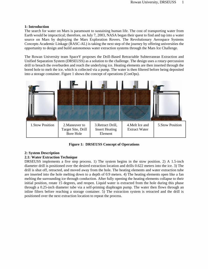
The Rowan University team SpaceY proposes the Drill-Based Retractable Subterranean Extraction and
Unified Separation System (DRSEUSS) as a solution to the challenge. The design uses a rotary-percussion
drill to breach the overburden and reach the underlying ice. Heating elements are then inserted through the
bored hole to melt the ice, which is collected via a pump. The water is then filtered before being deposited
into a storage container. Figure 1 shows the concept of operations (ConOps).
1.Stow Position 2.Maneuver to
Target Site, Drill
Bore Hole
3.Retract Drill,
Insert Heating
Element
4.Melt Ice and
Extract Water
5.Stow Position
Figure 1: DRSEUSS Concept of Operations
2: System Description
2.1: Water Extraction Technique DRSEUSS implements a five step process. 1) The system begins in the stow position. 2) A 1.5-inch
diameter drill is positioned over the desired extraction location and drills 0.622 meters into the ice. 3) The
drill is shut off, retracted, and moved away from the hole. The heating elements and water extraction tube
are inserted into the hole melting down to a depth of 0.9 meters. 4) The heating elements open like a fan
melting the surrounding ice through conduction. After fully opening the heating elements collapse to their
initial position, rotate 15 degrees, and reopen. Liquid water is extracted from the hole during this phase
through a 0.25-inch diameter tube via a self-priming diaphragm pump. The water then flows through an
inline filters before reaching a storage container. 5) The extraction system is retracted and the drill is
positioned over the next extraction location to repeat the process.
Rowan University, DRSEUSS 2
2.2: Mounting System
DRSEUSS is bolted to 2x4s on either side of the test box through
frame gussets. Figure 2 shows one of four gussets, one at each
corner of the base, which provide sufficient stability to the system.
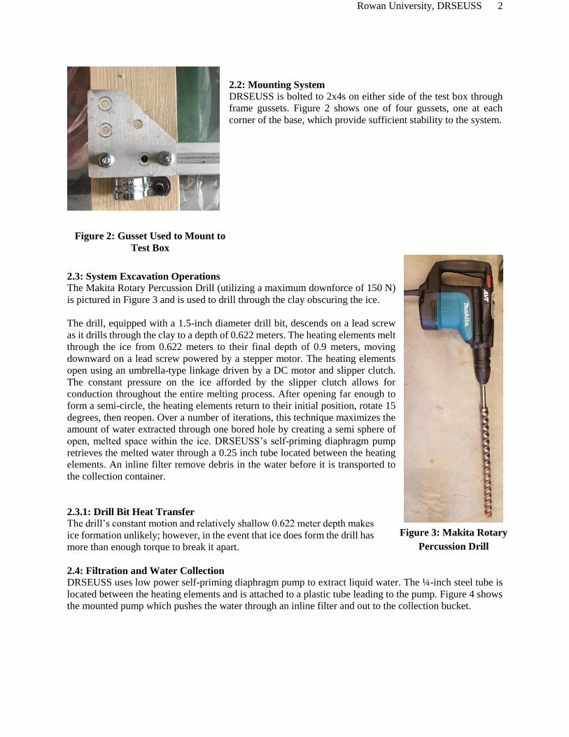
2.3: System Excavation Operations
The Makita Rotary Percussion Drill (utilizing a maximum downforce of 150 N)
is pictured in Figure 3 and is used to drill through the clay obscuring the ice.
The drill, equipped with a 1.5-inch diameter drill bit, descends on a lead screw
as it drills through the clay to a depth of 0.622 meters. The heating elements melt
through the ice from 0.622 meters to their final depth of 0.9 meters, moving
downward on a lead screw powered by a stepper motor. The heating elements
open using an umbrella-type linkage driven by a DC motor and slipper clutch.
The constant pressure on the ice afforded by the slipper clutch allows for
conduction throughout the entire melting process. After opening far enough to
form a semi-circle, the heating elements return to their initial position, rotate 15
degrees, then reopen. Over a number of iterations, this technique maximizes the
amount of water extracted through one bored hole by creating a semi sphere of
open, melted space within the ice. DRSEUSS’s self-priming diaphragm pump
retrieves the melted water through a 0.25 inch tube located between the heating
elements. An inline filter remove debris in the water before it is transported to
the collection container.
2.3.1: Drill Bit Heat Transfer The drill’s constant motion and relatively shallow 0.622 meter depth makes
ice formation unlikely; however, in the event that ice does form the drill has
more than enough torque to break it apart.
2.4: Filtration and Water Collection DRSEUSS uses low power self-priming diaphragm pump to extract liquid water. The ¼-inch steel tube is
located between the heating elements and is attached to a plastic tube leading to the pump. Figure 4 shows
the mounted pump which pushes the water through an inline filter and out to the collection bucket.
Figure 3: Makita Rotary
Percussion Drill
Figure 2: Gusset Used to Mount to
Test Box

Rowan University, DRSEUSS 3
Figure 4: Mounted Pump and Filter
The 0.1-micron mini-Sawyer filter employed by DRSEUSS was tested to verify its capabilities. Figure 5
shows the difference in the purity of the water before and after passing through the filter. The ratio of clay
to water in the left cup is 1:10, greater than is anticipated in even a worse-case scenario.
Figure 5: Clay Filled Water (left) and Filtered Water Using the Sawyer Filter (right)
2.5: Overburden Collapse Contingency
The support tube for the extraction system encompasses 93% of the drilled hole, preventing large
particulates from falling into the ice. Any debris capable of fitting through the 1.27-millimeter gap between
the tube and the wall of the hole is small enough to be removed by the extraction tube and filtered out. A
secondary safety in the form of a mesh covering the extraction tube blocks anything large enough to cause
clogs.
Due to DRSEUSS’ unique method of melting the ice, there is a risk that the structural integrity of the ice
could be compromised and the overburden could collapse into the mined cavity. To preserve the integrity
of the ice, the heating elements will leave some of the ice between the cut ravines, producing a final cutting
pattern similar in shape to an asterisk. In the event of an overburden collapse, the extraction system is
designed to retract to its stow position through a slipper clutch driven by the force of the falling overburden.
The heating elements are then shut off and the extraction system retracted to allow a new hole to be drilled.
2.6: Control and Communication System
The main decision-making system of DRSEUSS is an ARM-based Raspberry Pi 3 single board computer.
The Raspberry Pi interfaces with a thermocouple, a current sensor, a linear potentiometer, and a MSP430
(MSP430F5529). The Raspberry Pi reads data from these sensors and, using Universal Asynchronous
Receiver Transmitter (UART) protocol, sends commands to the MSP430. The Raspberry Pi also has a user
interface displayed on an external monitor to allow user control over the system. The MSP430 and
Raspberry Pi were chosen due to ease of use and familiarity.
The MSP430 is connected to the drill, pump, heating system, encoders, a DC motor, and 4 stepper motors.
The MSP receives a control word from the Raspberry Pi, giving it command over which element to activate
Rowan University, DRSEUSS 4
and how. The first three bits determine which system to work on, and the following five provide the action
requested. The encoders on the x-axis motors are kept within one degree of each other. If they separate, the
MSP will hold the leading motor until the other catches up.
The stepper motors are controlled using a DRV8833 stepper motor driver. The DC motor is controlled by
a L298N dual full-bridge driver. The heating element, pump, and drill are all modulated by sending a PWM
signal to a power MOSFET.
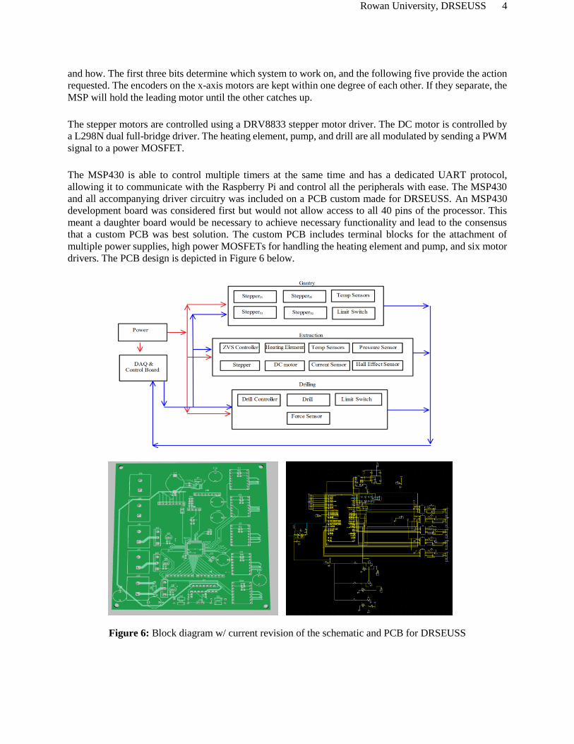
The MSP430 is able to control multiple timers at the same time and has a dedicated UART protocol,
allowing it to communicate with the Raspberry Pi and control all the peripherals with ease. The MSP430
and all accompanying driver circuitry was included on a PCB custom made for DRSEUSS. An MSP430
development board was considered first but would not allow access to all 40 pins of the processor. This
meant a daughter board would be necessary to achieve necessary functionality and lead to the consensus
that a custom PCB was best solution. The custom PCB includes terminal blocks for the attachment of
multiple power supplies, high power MOSFETs for handling the heating element and pump, and six motor
drivers. The PCB design is depicted in Figure 6 below.
Figure 6: Block diagram w/ current revision of the schematic and PCB for DRSEUSS
Rowan University, DRSEUSS 5
2.7: Data logger
The Raspberry Pi makes decisions based on date receives from the sensors. It alters the power to the heating
elements or the lowering force of the drill by raising or lowering their respective PWMs. The Raspberry Pi
then outputs the data back to the user interface for visualization and saves the data locally for verification
and analysis.
3: Technical Specifications
The overall specifications of the system are listed as Appendix 1. Two requirements listed in the
competition guidelines greatly affected the specifications of DRSEUSS: The prototype’s power
consumption cannot exceed 120V 10A AC and the drill must operate with less than 150 N of downward
force at any given time. On the electrical side, communication between boards was handled over UART
between a custom MSP430 board and a Raspberry Pi.
4: Challenges and Improvements
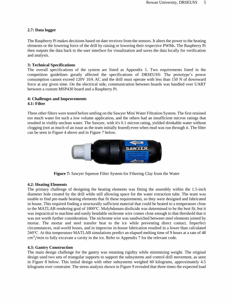
4.1: Filter
Three other filters were tested before settling on the Sawyer Mini Water Filtration System. The first retained
too much water for such a low volume application, and the others had an insufficient micron ratings that
resulted in visibly unclean water. The Sawyer, with it's 0.1 micron rating, yielded drinkable water without
clogging (not as much of an issue as the team initially feared) even when mud was run through it. The filter
can be seen in Figure 4 above and in Figure 7 below.
Figure 7: Sawyer Squeeze Filter System for Filtering Clay from the Water
4.2: Heating Elements
The primary challenge of designing the heating elements was fitting the assembly within the 1.5-inch
diameter hole created by the drill while still allowing space for the water extraction tube. The team was
unable to find pre-made heating elements that fit these requirements, so they were designed and fabricated
in house. This required finding a structurally sufficient material that could be heated to a temperature close
to the MATLAB rendering goal of 1800℃. Molybdenum disilicide was determined to be the best fit, but it
was impractical to machine and easily bendable nichrome wire comes close enough to that threshold that it
was not worth further consideration. The nichrome wire was sandwiched between steel elements joined by
mortar. The mortar and steel transfer heat to the ice while preventing direct contact. Imperfect
circumstances, real-world losses, and in imprecise in-house fabrication resulted in a lower than calculated
260℃. At this temperature MATLAB simulations predict an elapsed melting time of 9 hours at a rate of 48
𝑐𝑚3/𝑚𝑖𝑛 to fully excavate a cavity in the ice. Refer to Appendix 7 for the relevant code.
4.3: Gantry Construction
The main design challenge for the gantry was retaining rigidity while minimizing weight. The original
design used two sets of triangular supports to support the subsystems and control drill movement, as seen
in Figure 8 below. This initial design with other subsystems weighed 60 kilograms, approximately 4.5
kilograms over constraint. The stress analysis shown in Figure 9 revealed that three times the expected load

Rowan University, DRSEUSS 6
was needed to affect structural integrity, prompting the removal of the smaller triangular supports. Two
bottom members were left for mounting to the test box.
Figure 8: Changes in Gantry Design from Original (left) to Competition (right)
Figure 9: Stress Analysis on the Original Gantry Design
In addition, the gantry subsystem traverses other subsystems through the use of lead screws and linear
railing. The original design consisted of two linear rails per lead screw to assure rigidity. This was reduced
to one rail per screw, lowering the subsystem weight by 3.63 kilograms.
4.4: Electrical Components The largest design hurdle for the electrical system was imposed by the strict power limit, and sourcing the
right power supply was further complicated by the cost of high amperage units. This had the greatest effect
on the heating elements which had to make due with less than the desired amount of power, leading to
redesign of the heating elements.
The original circuit design called for a single MSP430 to power the circuit; however, the need for more
pins and greater processing power lead to the use of a Raspberry Pi 3 for the interface and reading of sensor
data. The Raspberry Pi relays commands to the MSP430 which controls the systems. Encoders are used to
measure gantry movement and check for slippage in the stepper motors, but attaching them posed a
challenge because through-hole encoders were not available to the team. Because the motors have one sided
Rowan University, DRSEUSS 7
outputs attached directly to the lead screws, the only way to measure rotation was to extend the lead screw
past the opposite bearings and mount the encoders there. Another hurdle was the minimum 4 week
turnaround time for the MSP430F5529 boards from the best available vendor. Revisions had to be kept to
a bare minimum, and testing of most systems had to be done using bread boards.
5: Overall Strategy for the Competition
Three primary methods are typically used to extract ice: fracking, coring, and melting. Fracking is infeasible
on Mars due to poor reclamation rates for the injected fluid, leaving coring and melting. The only additional
component needed for the melting method is a relatively low-power pump, while the coring method requires
a high-power drill and still requires a melting system above ground. As a result, heating is more electricity
efficient, allowing for a higher melting rate when all available power is used.
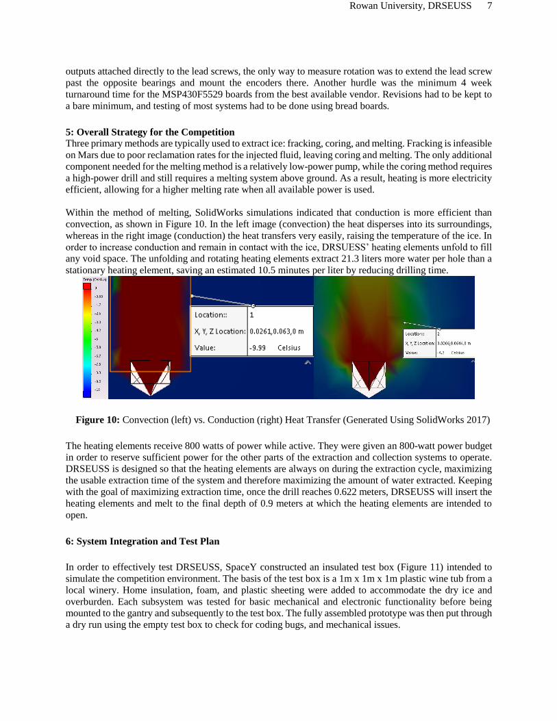
Within the method of melting, SolidWorks simulations indicated that conduction is more efficient than
convection, as shown in Figure 10. In the left image (convection) the heat disperses into its surroundings,
whereas in the right image (conduction) the heat transfers very easily, raising the temperature of the ice. In
order to increase conduction and remain in contact with the ice, DRSUESS’ heating elements unfold to fill
any void space. The unfolding and rotating heating elements extract 21.3 liters more water per hole than a
stationary heating element, saving an estimated 10.5 minutes per liter by reducing drilling time.
Figure 10: Convection (left) vs. Conduction (right) Heat Transfer (Generated Using SolidWorks 2017)
The heating elements receive 800 watts of power while active. They were given an 800-watt power budget
in order to reserve sufficient power for the other parts of the extraction and collection systems to operate.
DRSEUSS is designed so that the heating elements are always on during the extraction cycle, maximizing
the usable extraction time of the system and therefore maximizing the amount of water extracted. Keeping
with the goal of maximizing extraction time, once the drill reaches 0.622 meters, DRSEUSS will insert the
heating elements and melt to the final depth of 0.9 meters at which the heating elements are intended to
open.
6: System Integration and Test Plan
In order to effectively test DRSEUSS, SpaceY constructed an insulated test box (Figure 11) intended to
simulate the competition environment. The basis of the test box is a 1m x 1m x 1m plastic wine tub from a
local winery. Home insulation, foam, and plastic sheeting were added to accommodate the dry ice and
overburden. Each subsystem was tested for basic mechanical and electronic functionality before being
mounted to the gantry and subsequently to the test box. The fully assembled prototype was then put through
a dry run using the empty test box to check for coding bugs, and mechanical issues.

Rowan University, DRSEUSS 8
Figure 11: Testing Box
6.1: Test Results for Fully Integrated Dry Run The first fully-integrated dry run proved successful, but
brought forward an important design flaw. The various
sub-systems were tested in every scenario they were
expected to face, one at a time. The ability of DRSEUSS
to adapt to non-ideal circumstances was also tested
through various loads/resistances manually placed on the
system. DRSEUSS reacted as expected to the loads and
continued to perform its tasks. If used in its current state,
SpaceY believes that the prototype would be capable of
accomplishing its intended purpose. However, the dry run
revealed that the z-axis is not rigid enough to prevent
substantial wobble in the drilling and extraction systems.
Figure 12 shows the first test of the drill’s movement
along the z-axis, during which the issue was discovered.
While not detrimental to the prototype’s performance, the
lack of rigidity would likely result in trial and error by an
active operator in order to fit the extraction system into the
drilled hole. The mechanical team is currently working on
a solution, which it intends to implement within the next
several days for further testing.
Figure 12: First Dry Run with Solo Drill
Rowan University, DRSEUSS 9
7: Contingency Plans
SpaceY will have tools and spare parts on hand during the official test at Langley in anticipation of
component failures, most notably back-up heating elements (the most likely component to fail).
Contingency plans in the event of an overburden collapse have already been discussed, but DRSEUSS is
capable of continuing to operate even if the slipper clutch does not backdrive properly during an overburden
collapse. If the heating elements and umbrella mechanism cannot be repaired well enough to open properly,
the backup heating elements can still extract water by melting down to depth and not opening. The method
is inefficient, but will allow the damaged system to continue to extract water. Additional mounting
components, such as bolts, hose clamps, and duck tape will also be available in case a mount breaks or any
components show a tendency to rattle loose.
To account for electrical failures, SpaceY will have duplicates of every electronic component and two
copies of the software used by DRSEUSS. Short circuits, overheating, and other specific electrical failures
are not anticipated, but it is reasonable to predict that a failure could occur over the course of two days of
testing due to the nature of electrical systems under continuous load.
8: Safety Plan
During the production of the prototype, students machining components followed the standard machining
safety guidelines enforced by Rowan University. These guidelines include up-to-date certifications for the
machinery, ANSI Z87.1 certified eye protection, and hearing protection when operating loud machinery for
longer than its posted hearing safety limit. The same regulations were adopted while working directly on
assembly of the prototype. Machined parts with sharp edges were filed or deburred an necessary, and gloves
are recommended while transporting components as a secondary safety.
The choice to manufacture the heating elements in house brought unique dangers. The heating elements are
constructed using refractory cement, a mildly dangerous chemical. When handling the cement, gloves and
safety glasses were required. The manufacturing process also included the use of a hot plate at 300℉ to
cure the cement. While on, the hot plate was placed in a location that limited the chances of accidental
contact. Welding gloves and vice grips were used to manipulate the heating elements on the plate, giving
two layers of protection from the heat.
While any part of the prototype is running, safety glasses are required. While there is no anticipated need
for protection from debris based on testing, safety glasses remove the possibility of eye injury in the event
of unexpected eventualities and malfunctions. Long hair must be tied back as well, and no loose clothing
should be worn around the system during operation to avoid entanglement with the moving parts of the
system. During drilling operations, hearing protection is also required. The Center for Disease Control and
Prevention (CDC) rated a 9/16-inch chuck Makita Hammer Drill as having a loaded-test sound level of 104
decibels [1] and recommends an exposure time no longer than 6 minutes [2]. After testing, special care is
taken when handling the heating elements. The elements must cool down for a minimum of 30 minutes
before being touched without a combination of welding gloves and vice grips. Everyone present is also
made aware any time that the heating elements are being moved before 30 minutes have passed.
The highest current used by DRSEUSS is 8.3 amps, drastically higher than the fatal threshold of 0.3 amps
[3]. All of the electrical components are insulated, but the prototype must still be turned off before any
modifications are made. Likewise, operators must always proceed with caution during operation.
DRSEUSS also has two emergency stops capable of disabling the prototype at any point: one mounted
directly to the gantry and one on the digital controller.
Rowan University, DRSEUSS 10
8.1 List of All Chemicals and Hazardous Materials Used
IMPERIAL 8-oz Stove and Fireplace Cement (Black): This hazardous material, known as refractory
cement, is used to electrically insulate the heating elements and to provide them with structural integrity.
The MSDS reports a health hazard of 1 on the 4 point scale [4].
9: Path-To-Flight
9.1: System Concept Development
From its inception, design of DRSEUSS has revolved around optimizing for efficiency. Based on the
constraints set forth by the project statement, the team researched traditional methods and brainstormed
alternative options. For each subsystem, SpaceY chose the method capable of most efficiently extracting
water that was able to be reliably implemented within the project constraints.
9.1.1: Gantry Design
The gantry passed through several design iterations due to a combination of light weighting and changes in
other subsystems. The iterative design work on the gantry used finite element analysis to produce the
lightest frame possible capable of properly supporting the components mounted to it (Figure 9). T-slot was
chosen for its unique ability to easily accept the mounts for the various subsystems without modification.
The gussets connecting the T-slot also save weight by serving a dual purpose: Wherever possible, the
gussets also act as mounts for the subsystems.
9.1.2: Heating Elements Design As has been previously discussed, the driving factors in the design of the heating elements were
maximization of the benefits of conduction (Figure 10) and minimization of drilling time. With this
information, SpaceY looked for a way to maintain contact with the ice for as long as possible, settling on
moving heating elements and a rotating support tube. The shape of the heating elements passed through
several iterations, starting with a coil, before evolving into the final “C” shape. The C shape keeps the
entirety of the heating elements in contact with the ice and lets them easily fit into the circular hole made
by the drill.
9.1.3: Powertrain Design
The powertrain was a sub-consideration of the heating element design. The unique design of the moving
heating elements and the rotating tube to which they are mounted requires a powertrain to control their
movement. The powertrain is the one subsystem that slightly sacrifices efficiency for the sake of reliability.
The ability of the system to survive an overburden collapse was deemed paramount over the several watts
of power that could be saved by using a direct-drive mechanism. The powertrain is powered by a reversible,
brushless, DC motor to protect the system when the heating elements close or during backdrive from an
overburden collapse. The slipper clutch was chosen because of its consistency and ease of implementation
when compared to other options such as a differential.
Finally, the umbrella mechanism was chosen because of the availability of parts. After struggling to
effectively implement the umbrella mechanism, SpaceY has confirmed the initial suspicion that a gear-
driven mechanism would be more effective. Due to being unable to effectively order the correct gears,
however, the team has been forced to continue to use the umbrella design. While it is not expected to
significantly affect DRSEUSS performance, reliability concerns prompt SpaceY to recommend further
research into converting to a geared mechanism powered by a driveshaft, as the team originally intended.
A detailed review of the design changes to the powertrain over time are beyond the scope of this document
(refer to the Mid-Project Review for further details).
9.1.4: Drill Selection
SpaceY researched the most effective types of drills for hard gravel and masonry work before deciding on
a rotary percussion drill. A rotary percussion drill beats the ground and spins like a conventional drill.

Rowan University, DRSEUSS 11
SpaceY also determined an auger bit to be the best option for the purposes of DRSEUSS because of its
ability to neatly remove dirt from the drilled hole and make room for the extraction system. After thorough
research, SpaceY found a Quad-Tipped Masonry drill bit with auger flutes that is capable of incorporating
rotary percussion motion..
The Makita HR4510C was chosen for two reasons: First, Makita’s patented anti-vibration technology
(AVT) came highly recommended by West Virginia University’s winning 2017 Mars Ice Challenge Team
[5]. Second, the drill is capable of housing the aforementioned hybrid bit the team wanted to use, which
requires a ¾ inch chuck as opposed to the standard ½ inch chuck found on most drills.
9.1.5: Pump and Filter Selection
When selecting the pump, SpaceY focussed on minimizing power consumption while still supplying the
minimum of 2 meters of head required to pump the water (with a 50% safety margin). The other concern
was self-priming. In order to successfully pump an inconsistent water supply, the pump cannot rely on
repeated priming.
The filter selection process was a matter of trial and error, owing to substantial discrepancies between the
listed performance of the filters and the team’s test results. Section 4.1 discusses the changes to the filtration
system in further detail. The end goal was drinkable water and the 0.1 micron mini-Sawyer filter achieved
that goal.
9.2: Modifications From Earth to Mars SpaceY’s stated goal in modifying the initially proposed design for Earth was to change as little as possible.
The only notable change to the design occured in the method of water collection.
9.2.1: Modifications to Heating Process
The atmospheric pressure of Mars, ~600 Pa, is slightly below water’s triple point, shown in Figure 13. As
a result, ice will sublimate rather than melt when the temperature is increased [6]. For use on Mars,
DRSEUSS would be modified to take advantage of the atmosphere by replacing the pump with an axial fan
that creates a vacuum inside the drilled hole. The fan would pull the steam created by the sublimation into
a heated tube for storage above the surface. An axial fan is used due to its simplicity and superior ability to
draw vapor through a sealed tube. To ensure that no vapor escapes, a skirt would seal the top of the drilled
hole. It was deemed impractical to collect the water in a liquid state by pressurizing the underground cavity.
Pressurization uses valuable energy and leaves impurities in the water which would be filtered out in a
gaseous state. Because the water is in a gaseous state, there is no need for the filter used in the Earth-based
version. The collected water is then stored as ice in a containment tank. This eliminates the need for heated
and pressurized storage when removing the water from the drilling station for use elsewhere on Mars.
Although ice is 8% less dense than liquid water (Murphy 2012) and will take up more volume, by
eliminating pressurized transportation vessels, valuable resources are saved.
Also, on Mars the team assumes that the ice will be very thick in some locations. The lengths of the drill
bit and the support tube for the heating elements would be lengthened to give DRSEUSS the ability to
sweep ice at varying heights. For example, the drill could drill down 10 meters. The heating elements can
then be lowered 10m, start the extraction sequence at current depth, then move upward or downward a set
distance and repeat the process. In this manner the heating elements would be able to reach more ice.

Rowan University, DRSEUSS 12
Figure 13: Triple Point of Water on Mars
9.2.2: Changes to Water Containment System DRSEUSS would use a compressor to pressurize two hexagonal, polybutylene storage tanks to 2 kPa,
creating liquid water between 0-20°C. The first, smaller storage tank would be heated, so the pressure forces
the vapor into a liquid before letting it flow into the larger, removable storage tank. The second storage tank
would not be heated, so the water would refreeze. Polybutylene is designed to expand with freezing water,
so the tank would not be damaged. Because the water is already frozen, there is no need to keep the
removable tank pressurized once it is removed, saving energy. Using a removable storage container
eliminates the difficult task of transferring water from one container to another through the Martian
atmosphere, making the process cheaper and faster. The tanks are hexagonal because hexagons have been
mathematically proven to be the optimal flat shape for optimizing weight and packing efficiency [7]. A
Mars mission would be expected to require many water storage tanks, making this an important
consideration.
9.2.3: Changes to Electrical Components
The initial electrical system used an msp430F5529 breakout board allowing access to all pins for testing
and prototyping. After initial tests a second version of the board was made, pins were mapped for
functionality and versatility. Upon testing the second design it was noticed where the board had a few issues
and could be improved. SpaceY is currently operating on revision 3 of the board and have made some
modification post manufacturing. We are currently looking to make a fourth revision if time allows.
9.2.4: Interplanetary Travel
The components of DRSEUSS are intended to be easily packaged into a small area for storage on a
spacecraft. Excluding the drill mounting plate, the large components are long and thin. When disassembled
and laid in a line on top of the drill mounting plate, the thin T-slot frame is a very space efficient solution.
The electrical components would require slight packaging, but were also designed with size and weight in
mind, making them insignificant in comparison to the rest of DRSEUSS. The hardware is standardized,
meaning reassembly on Mars only requires a set of English Allen keys and an adjustable wrench, tools that
are expected to be readily available on an actively developing colony.
Rowan University, DRSEUSS 13
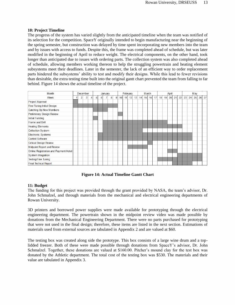
10: Project Timeline
The progress of the system has varied slightly from the anticipated timeline when the team was notified of
its selection for the competition. SpaceY originally intended to begin manufacturing near the beginning of
the spring semester, but construction was delayed by time spent incorporating new members into the team
and by issues with access to funds. Despite this, the frame was completed ahead of schedule, but was later
modified in the beginning of April to reduce weight. The electrical components, on the other hand, took
longer than anticipated due to issues with ordering parts. The collection system was also completed ahead
of schedule, allowing members working thereon to help the struggling powertrain and heating element
subsystems meet their deadlines. Later in the semester, the lack of an efficient way to order replacement
parts hindered the subsystems’ ability to test and modify their designs. While this lead to fewer revisions
than desirable, the extra testing time built into the original gantt chart prevented the team from falling to far
behind. Figure 14 shows the actual timeline of the project.
Figure 14: Actual Timeline Gantt Chart
11: Budget
The funding for this project was provided through the grant provided by NASA, the team’s advisor, Dr.
John Schmalzel, and through materials from the mechanical and electrical engineering departments of
Rowan University.
3D printers and borrowed power supplies were made available for prototyping through the electrical
engineering department. The powertrain shown in the midpoint review video was made possible by
donations from the Mechanical Engineering Department. There were no parts purchased for prototyping
that were not used in the final design; therefore, these items are listed in the next section. Estimations of
materials used from external sources are tabulated in Appendix 2 and are valued at $60.
The testing box was created along side the prototype. This box consists of a large wine drum and a top-
lidded freezer. Both of these were made possible through donations from SpaceY’s advisor, Dr. John
Schmalzel. Together, these donations are valued at $160.00. Pitcher’s mound clay for the test box was
donated by the Athletic department. The total cost of the testing box was $530. The materials and their
value are tabulated in Appendix 3.
Rowan University, DRSEUSS 14
Building materials were purchased through the ECE department using funding provided through the NASA
grants. Appendix 4 illustrates where the funding was used for each subsystem, with a total value of $4,003.
Transportation of the team members and DRSEUSS will use funding from the NASA grant. This section
includes: hotel, travelling meals, fuel per diem, and event registration. These expenses are tabulated in
Appendix 5 and account for the five competing team members and the team’s advisor. The total anticipated
cost is $3,566. The hotel, meal, and fuel reimbursements are set by the US General Service Administration.
The total cost of the project is tabulated in Appendix 6. It does not consider the cost of facility usage such
as machining costs. The final estimated cost is $8,159, $830 more than last semester’s report had
anticipated. Most of the additional cost resulted from the school’s purchasing policy which requires parts
to be purchased from approved vendors and subsequently tends to raise costs.
Rowan University, DRSEUSS 15
References Cited
[1] Wwwn.cdc.gov. (2018). CDC - Powertools Database - NIOSH. Accessed March 1, 2018
https://wwwn.cdc.gov/niosh-sound-vibration/
[2] “Criteria for a Recommended Standard” Accessed April 26, 2018 https://www.cdc.gov/niosh/docs/98-
126/pdfs/98-126.pdf
[3] “Electrical Hazards Train the Trainer Manual” Accessed April 26, 2018
https://www.osha.gov/dte/grant_materials/fy07/sh-16615-07/train-the-trainer_manual2.pdf
[4] “MSDS Refractory Cement” Accessed April 26, 2018
http://www.paragonweb.com/files/manuals/MSDS_Refractory_Cement.pdf
[5] “West Virginia University 2015 Mars Rover Proposal” Accessed April 26, 2018
http://specialedition.rascal.nianet.org/wp-content/uploads/2017/09/WVU-Klink_2017-MIC-Technical-
Report.pdf
[6] Murphy, Tom. "Burning Desire for Efficiency ." Do the Math. May 29, 2012. Accessed October 26,
2017. https://dothemath.ucsd.edu/2012/05/burning-desire-for-efficiency
[7] Tóth, L. Fejes. “What the Bees Know and What They do not Know.” Bull Amer. Math. Soc. 70, no. 4
(1964): 468-481.
Appendices:
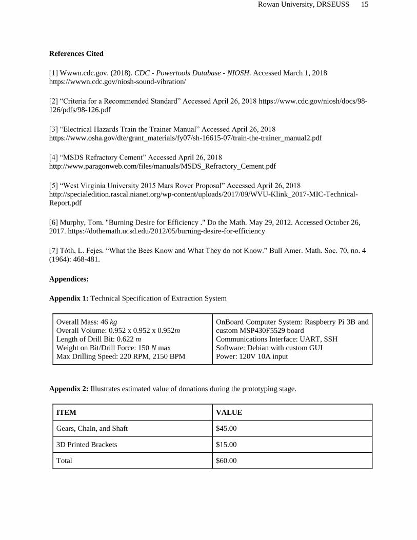
Appendix 1: Technical Specification of Extraction System
Overall Mass: 46 kg
Overall Volume: 0.952 x 0.952 x 0.952m
Length of Drill Bit: 0.622 m
Weight on Bit/Drill Force: 150 N max
Max Drilling Speed: 220 RPM, 2150 BPM
OnBoard Computer System: Raspberry Pi 3B and
custom MSP430F5529 board
Communications Interface: UART, SSH
Software: Debian with custom GUI
Power: 120V 10A input
Appendix 2: Illustrates estimated value of donations during the prototyping stage.
ITEM VALUE
Gears, Chain, and Shaft $45.00
3D Printed Brackets $15.00
Total $60.00

Rowan University, DRSEUSS 16
Appendix 3: Illustrates cost of testing box.
ITEM VALUE
Wine Drum $100.00
Freezer $60.00
Insulation Materials $120.00
Pitcher Mound Clay $250.00
Total $530.00
Appendix 4 : Illustrates spending distribution towards building materials of the final design
SYSTEM VALUE
Gantry System $1,382.99
Ice Extraction System $1,203.94
Electrical Control System $866.77
Power Transfer System $351.55
Heating Element System $144.39
Collection and Filtration System $53.35
Total $4,003.00
Appendix 5: Illustrates ongoing spending budgeted for travel expenses
ITEM VALUE
Travel Meals (GSA Guidelines) $720.00
Event Registration $1,650.00
Hotel Reservation $824.00
Fuel (GSA Guidelines) $371.00
Total $3,566.00
Rowan University, DRSEUSS 17
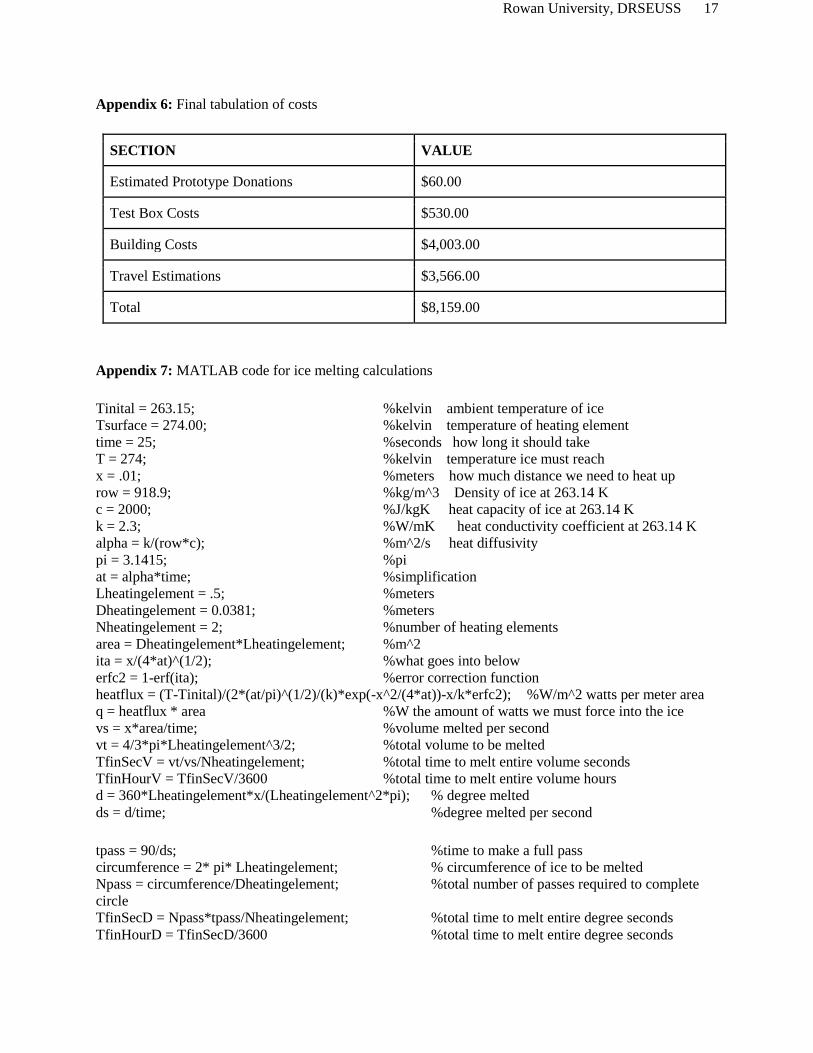
Appendix 6: Final tabulation of costs
SECTION VALUE
Estimated Prototype Donations $60.00
Test Box Costs $530.00
Building Costs $4,003.00
Travel Estimations $3,566.00
Total $8,159.00
Appendix 7: MATLAB code for ice melting calculations
Tinital = 263.15; %kelvin ambient temperature of ice
Tsurface = 274.00; %kelvin temperature of heating element
time = 25; %seconds how long it should take
T = 274; %kelvin temperature ice must reach
x = .01; %meters how much distance we need to heat up
row = 918.9; %kg/m^3 Density of ice at 263.14 K
c = 2000; %J/kgK heat capacity of ice at 263.14 K
k = 2.3; %W/mK heat conductivity coefficient at 263.14 K
alpha = k/(row*c); %m^2/s heat diffusivity
pi = 3.1415; %pi
at = alpha*time; %simplification
Lheatingelement = .5; %meters
Dheatingelement = 0.0381; %meters
Nheatingelement = 2; %number of heating elements
area = Dheatingelement*Lheatingelement; %m^2
ita = x/(4*at)^(1/2); %what goes into below
erfc2 = 1-erf(ita); %error correction function
heatflux = (T-Tinital)/(2*(at/pi)^(1/2)/(k)*exp(-x^2/(4*at))-x/k*erfc2); %W/m^2 watts per meter area
q = heatflux * area %W the amount of watts we must force into the ice
vs = x*area/time; %volume melted per second
vt = 4/3*pi*Lheatingelement^3/2; %total volume to be melted
TfinSecV = vt/vs/Nheatingelement; %total time to melt entire volume seconds
TfinHourV = TfinSecV/3600 %total time to melt entire volume hours
d = 360*Lheatingelement*x/(Lheatingelement^2*pi); % degree melted
ds = d/time; %degree melted per second
tpass = 90/ds; %time to make a full pass
circumference = 2* pi* Lheatingelement; % circumference of ice to be melted
Npass = circumference/Dheatingelement; %total number of passes required to complete
circle
TfinSecD = Npass*tpass/Nheatingelement; %total time to melt entire degree seconds
TfinHourD = TfinSecD/3600 %total time to melt entire degree seconds