routing protocols guide - nokia...
TRANSCRIPT

7750 SR OSRouting Protocols Guide
Software Version: 7750 SR OS 10.0.R1February 2012Document Part Number: 93-0074-09-01
*93-0074-08-05*

This document is protected by copyright. Except as specifically permitted herein, no portion of the provided information can be reproduced in any form, or by any means, without prior written permission from Alcatel-Lucent.Alcatel, Lucent, Alcatel-Lucent and the Alcatel-Lucent logo are trademarks of Alcatel-Lucent. All other trademarks are the property of their respective owners.The information presented is subject to change without notice.Alcatel-Lucent assumes no responsibility for inaccuracies contained herein.
Copyright 2012 Alcatel-Lucent. All rights reserved.

Table of Contents
Preface. . . . . . . . . . . . . . . . . . . . . . . . . . . . . . . . . . . . . . . . . . . . . . . . . . . . . . . . . . . . . . . . . . . . . . . . . . . . . .15
Getting StartedAlcatel-Lucent 7750 SR-Series Router Configuration Process . . . . . . . . . . . . . . . . . . . . . . . . . . . . . . . . .19
MulticastIntroduction to Multicast . . . . . . . . . . . . . . . . . . . . . . . . . . . . . . . . . . . . . . . . . . . . . . . . . . . . . . . . . . . . . . .22
Multicast Models . . . . . . . . . . . . . . . . . . . . . . . . . . . . . . . . . . . . . . . . . . . . . . . . . . . . . . . . . . . . . . . . . .23Any-Source Multicast (ASM) . . . . . . . . . . . . . . . . . . . . . . . . . . . . . . . . . . . . . . . . . . . . . . . . . . . . . .23Source Specific Multicast (SSM) . . . . . . . . . . . . . . . . . . . . . . . . . . . . . . . . . . . . . . . . . . . . . . . . . . .23
IPv6 Multicast . . . . . . . . . . . . . . . . . . . . . . . . . . . . . . . . . . . . . . . . . . . . . . . . . . . . . . . . . . . . . . . . . . . . . . .25Multicast Listener Discovery (MLD v1 and v2) . . . . . . . . . . . . . . . . . . . . . . . . . . . . . . . . . . . . . . . . . . .25PIM SSM . . . . . . . . . . . . . . . . . . . . . . . . . . . . . . . . . . . . . . . . . . . . . . . . . . . . . . . . . . . . . . . . . . . . . . . .25IPv6 PIM ASM . . . . . . . . . . . . . . . . . . . . . . . . . . . . . . . . . . . . . . . . . . . . . . . . . . . . . . . . . . . . . . . . . . . .26Embedded RP . . . . . . . . . . . . . . . . . . . . . . . . . . . . . . . . . . . . . . . . . . . . . . . . . . . . . . . . . . . . . . . . . . . .26
Core Router Multicast Requirements . . . . . . . . . . . . . . . . . . . . . . . . . . . . . . . . . . . . . . . . . . . . . . . . . . . . .27Internet Group Management Protocol . . . . . . . . . . . . . . . . . . . . . . . . . . . . . . . . . . . . . . . . . . . . . . . . . .27
IGMP Versions and Interoperability Requirements . . . . . . . . . . . . . . . . . . . . . . . . . . . . . . . . . . . . .28IGMP Version Transition . . . . . . . . . . . . . . . . . . . . . . . . . . . . . . . . . . . . . . . . . . . . . . . . . . . . . . . . .28
Source-Specific Multicast Groups . . . . . . . . . . . . . . . . . . . . . . . . . . . . . . . . . . . . . . . . . . . . . . . . . . . . .29Protocol Independent Multicast Sparse Mode (PIM-SM) . . . . . . . . . . . . . . . . . . . . . . . . . . . . . . . . . . .30
PIM-SM Functions . . . . . . . . . . . . . . . . . . . . . . . . . . . . . . . . . . . . . . . . . . . . . . . . . . . . . . . . . . . . . .30Encapsulating Data Packets in the Register Tunnel . . . . . . . . . . . . . . . . . . . . . . . . . . . . . . . . . . . .33PIM Bootstrap Router Mechanism . . . . . . . . . . . . . . . . . . . . . . . . . . . . . . . . . . . . . . . . . . . . . . . . . .33PIM-SM Routing Policies . . . . . . . . . . . . . . . . . . . . . . . . . . . . . . . . . . . . . . . . . . . . . . . . . . . . . . . . .33Reverse Path Forwarding Checks . . . . . . . . . . . . . . . . . . . . . . . . . . . . . . . . . . . . . . . . . . . . . . . . . .35Anycast RP for PIM-SM . . . . . . . . . . . . . . . . . . . . . . . . . . . . . . . . . . . . . . . . . . . . . . . . . . . . . . . . . .36Auto-RP (discovery mode only) in Multicast VPN . . . . . . . . . . . . . . . . . . . . . . . . . . . . . . . . . . . . . .39
Multicast Extensions to MBGP . . . . . . . . . . . . . . . . . . . . . . . . . . . . . . . . . . . . . . . . . . . . . . . . . . . . . . .40MBGP Multicast Topology Support . . . . . . . . . . . . . . . . . . . . . . . . . . . . . . . . . . . . . . . . . . . . . . . . .40
Multicast Source Discovery Protocol (MSDP) . . . . . . . . . . . . . . . . . . . . . . . . . . . . . . . . . . . . . . . . . . . .41Anycast RP for MSDP . . . . . . . . . . . . . . . . . . . . . . . . . . . . . . . . . . . . . . . . . . . . . . . . . . . . . . . . . . .41MSDP Procedure . . . . . . . . . . . . . . . . . . . . . . . . . . . . . . . . . . . . . . . . . . . . . . . . . . . . . . . . . . . . . . .42MSDP Peer Groups . . . . . . . . . . . . . . . . . . . . . . . . . . . . . . . . . . . . . . . . . . . . . . . . . . . . . . . . . . . . .43MSDP Mesh Groups . . . . . . . . . . . . . . . . . . . . . . . . . . . . . . . . . . . . . . . . . . . . . . . . . . . . . . . . . . . .43MSDP Routing Policies . . . . . . . . . . . . . . . . . . . . . . . . . . . . . . . . . . . . . . . . . . . . . . . . . . . . . . . . . .44Multicast in Virtual Private Networks . . . . . . . . . . . . . . . . . . . . . . . . . . . . . . . . . . . . . . . . . . . . . . . .45
Multicast Debugging Tools . . . . . . . . . . . . . . . . . . . . . . . . . . . . . . . . . . . . . . . . . . . . . . . . . . . . . . . . . .46Mtrace . . . . . . . . . . . . . . . . . . . . . . . . . . . . . . . . . . . . . . . . . . . . . . . . . . . . . . . . . . . . . . . . . . . . . . .46Mstat. . . . . . . . . . . . . . . . . . . . . . . . . . . . . . . . . . . . . . . . . . . . . . . . . . . . . . . . . . . . . . . . . . . . . . . . .48Mrinfo . . . . . . . . . . . . . . . . . . . . . . . . . . . . . . . . . . . . . . . . . . . . . . . . . . . . . . . . . . . . . . . . . . . . . . . .48
Multicast Connection Admission Control (MCAC) . . . . . . . . . . . . . . . . . . . . . . . . . . . . . . . . . . . . . . . . .49BTV . . . . . . . . . . . . . . . . . . . . . . . . . . . . . . . . . . . . . . . . . . . . . . . . . . . . . . . . . . . . . . . . . . . . . . . . .49Interface-Level CAC . . . . . . . . . . . . . . . . . . . . . . . . . . . . . . . . . . . . . . . . . . . . . . . . . . . . . . . . . . . . .53Bundle-Level CAC . . . . . . . . . . . . . . . . . . . . . . . . . . . . . . . . . . . . . . . . . . . . . . . . . . . . . . . . . . . . . .53
7750 SR OS Routing Protocols Guide Page 3

Table of Contents
Dealing with Configuration Changes . . . . . . . . . . . . . . . . . . . . . . . . . . . . . . . . . . . . . . . . . . . . . . . .53Distributing PIM Joins over Multiple ECMP Paths. . . . . . . . . . . . . . . . . . . . . . . . . . . . . . . . . . . . . . . . .55LAG Interworking. . . . . . . . . . . . . . . . . . . . . . . . . . . . . . . . . . . . . . . . . . . . . . . . . . . . . . . . . . . . . . . . . .59
CAC Policy for Split Horizon Groups . . . . . . . . . . . . . . . . . . . . . . . . . . . . . . . . . . . . . . . . . . . . . . . .60Dynamic Multicast Signaling over P2MP LDP. . . . . . . . . . . . . . . . . . . . . . . . . . . . . . . . . . . . . . . . . . . .61
Multicast Configuration Process Overview . . . . . . . . . . . . . . . . . . . . . . . . . . . . . . . . . . . . . . . . . . . . . . . . .62Configuration Notes . . . . . . . . . . . . . . . . . . . . . . . . . . . . . . . . . . . . . . . . . . . . . . . . . . . . . . . . . . . . . . . . . .63
General . . . . . . . . . . . . . . . . . . . . . . . . . . . . . . . . . . . . . . . . . . . . . . . . . . . . . . . . . . . . . . . . . . . . . . . . .63Configuring Multicast Parameters with CLI. . . . . . . . . . . . . . . . . . . . . . . . . . . . . . . . . . . . . . . . . . . . . . . . .65Multicast Configuration Overview . . . . . . . . . . . . . . . . . . . . . . . . . . . . . . . . . . . . . . . . . . . . . . . . . . . . . . . .66Basic Configuration. . . . . . . . . . . . . . . . . . . . . . . . . . . . . . . . . . . . . . . . . . . . . . . . . . . . . . . . . . . . . . . . . . .67Common Configuration Tasks . . . . . . . . . . . . . . . . . . . . . . . . . . . . . . . . . . . . . . . . . . . . . . . . . . . . . . . . . .70
Configuring IGMP Parameters . . . . . . . . . . . . . . . . . . . . . . . . . . . . . . . . . . . . . . . . . . . . . . . . . . . . . . .70Enabling IGMP . . . . . . . . . . . . . . . . . . . . . . . . . . . . . . . . . . . . . . . . . . . . . . . . . . . . . . . . . . . . . . . . .70Configuring an IGMP Interface. . . . . . . . . . . . . . . . . . . . . . . . . . . . . . . . . . . . . . . . . . . . . . . . . . . . .71Configuring Static Parameters . . . . . . . . . . . . . . . . . . . . . . . . . . . . . . . . . . . . . . . . . . . . . . . . . . . . .72Configuring SSM Translation . . . . . . . . . . . . . . . . . . . . . . . . . . . . . . . . . . . . . . . . . . . . . . . . . . . . . .74
Configuring PIM Parameters . . . . . . . . . . . . . . . . . . . . . . . . . . . . . . . . . . . . . . . . . . . . . . . . . . . . . . . . .75Enabling PIM . . . . . . . . . . . . . . . . . . . . . . . . . . . . . . . . . . . . . . . . . . . . . . . . . . . . . . . . . . . . . . . . . .75Configuring PIM Interface Parameters . . . . . . . . . . . . . . . . . . . . . . . . . . . . . . . . . . . . . . . . . . . . . . .76Importing PIM Join/Register Policies . . . . . . . . . . . . . . . . . . . . . . . . . . . . . . . . . . . . . . . . . . . . . . . .81
Configuring Multicast Source Discovery Protocol (MSDP) Parameters . . . . . . . . . . . . . . . . . . . . . . . .83Configuring MCAC Parameters . . . . . . . . . . . . . . . . . . . . . . . . . . . . . . . . . . . . . . . . . . . . . . . . . . . . . . .84
Service Management Tasks . . . . . . . . . . . . . . . . . . . . . . . . . . . . . . . . . . . . . . . . . . . . . . . . . . . . . . . . . . . .87Disabling IGMP or PIM . . . . . . . . . . . . . . . . . . . . . . . . . . . . . . . . . . . . . . . . . . . . . . . . . . . . . . . . . . . . .87
Multicast Command Reference . . . . . . . . . . . . . . . . . . . . . . . . . . . . . . . . . . . . . . . . . . . . . . . . . . . . . . . . .91Configuration Commands . . . . . . . . . . . . . . . . . . . . . . . . . . . . . . . . . . . . . . . . . . . . . . . . . . . . . . . . . .105
Generic Commands . . . . . . . . . . . . . . . . . . . . . . . . . . . . . . . . . . . . . . . . . . . . . . . . . . . . . . . . . . . .105Router IGMP Commands . . . . . . . . . . . . . . . . . . . . . . . . . . . . . . . . . . . . . . . . . . . . . . . . . . . . . . . .108Router PIM Commands . . . . . . . . . . . . . . . . . . . . . . . . . . . . . . . . . . . . . . . . . . . . . . . . . . . . . . . . .117Multicast CAC Policy Configuration Commands . . . . . . . . . . . . . . . . . . . . . . . . . . . . . . . . . . . . . .144MLD Commands . . . . . . . . . . . . . . . . . . . . . . . . . . . . . . . . . . . . . . . . . . . . . . . . . . . . . . . . . . . . . .151Operational Commands . . . . . . . . . . . . . . . . . . . . . . . . . . . . . . . . . . . . . . . . . . . . . . . . . . . . . . . . .157
Show Commands . . . . . . . . . . . . . . . . . . . . . . . . . . . . . . . . . . . . . . . . . . . . . . . . . . . . . . . . . . . . . . . .163IGMP Commands. . . . . . . . . . . . . . . . . . . . . . . . . . . . . . . . . . . . . . . . . . . . . . . . . . . . . . . . . . . . . .163
Show Router PIM Commands . . . . . . . . . . . . . . . . . . . . . . . . . . . . . . . . . . . . . . . . . . . . . . . . . . . . . . .176Clear Commands. . . . . . . . . . . . . . . . . . . . . . . . . . . . . . . . . . . . . . . . . . . . . . . . . . . . . . . . . . . . . . . . .216Debug Commands. . . . . . . . . . . . . . . . . . . . . . . . . . . . . . . . . . . . . . . . . . . . . . . . . . . . . . . . . . . . . . . .224
Debug IGMP Commands . . . . . . . . . . . . . . . . . . . . . . . . . . . . . . . . . . . . . . . . . . . . . . . . . . . . . . . .224Debug PIM Commands . . . . . . . . . . . . . . . . . . . . . . . . . . . . . . . . . . . . . . . . . . . . . . . . . . . . . . . . .227
RIPRIP Overview . . . . . . . . . . . . . . . . . . . . . . . . . . . . . . . . . . . . . . . . . . . . . . . . . . . . . . . . . . . . . . . . . . . . . .234
RIP Features . . . . . . . . . . . . . . . . . . . . . . . . . . . . . . . . . . . . . . . . . . . . . . . . . . . . . . . . . . . . . . . . . . . .235RIP Version Types . . . . . . . . . . . . . . . . . . . . . . . . . . . . . . . . . . . . . . . . . . . . . . . . . . . . . . . . . . . . .235RIPv2 Authentication . . . . . . . . . . . . . . . . . . . . . . . . . . . . . . . . . . . . . . . . . . . . . . . . . . . . . . . . . . .235Metrics . . . . . . . . . . . . . . . . . . . . . . . . . . . . . . . . . . . . . . . . . . . . . . . . . . . . . . . . . . . . . . . . . . . . . .236Timers . . . . . . . . . . . . . . . . . . . . . . . . . . . . . . . . . . . . . . . . . . . . . . . . . . . . . . . . . . . . . . . . . . . . . .236Import and Export Policies . . . . . . . . . . . . . . . . . . . . . . . . . . . . . . . . . . . . . . . . . . . . . . . . . . . . . . .236
Page 4 7750 SR OS Routing Protocols Guide

Table of Contents
RIP Packet Format . . . . . . . . . . . . . . . . . . . . . . . . . . . . . . . . . . . . . . . . . . . . . . . . . . . . . . . . . . . . .237Hierarchical Levels . . . . . . . . . . . . . . . . . . . . . . . . . . . . . . . . . . . . . . . . . . . . . . . . . . . . . . . . . . . . . . .239
RIP Configuration Process Overview . . . . . . . . . . . . . . . . . . . . . . . . . . . . . . . . . . . . . . . . . . . . . . . . . . . .240Configuration Notes . . . . . . . . . . . . . . . . . . . . . . . . . . . . . . . . . . . . . . . . . . . . . . . . . . . . . . . . . . . . . . . . .241
General . . . . . . . . . . . . . . . . . . . . . . . . . . . . . . . . . . . . . . . . . . . . . . . . . . . . . . . . . . . . . . . . . . . . . . . .241Configuring RIP with CLI . . . . . . . . . . . . . . . . . . . . . . . . . . . . . . . . . . . . . . . . . . . . . . . . . . . . . . . . . . . . .243RIP Configuration Overview . . . . . . . . . . . . . . . . . . . . . . . . . . . . . . . . . . . . . . . . . . . . . . . . . . . . . . . . . . .244
Preconfiguration Requirements . . . . . . . . . . . . . . . . . . . . . . . . . . . . . . . . . . . . . . . . . . . . . . . . . . . . . .244RIP Hierarchy . . . . . . . . . . . . . . . . . . . . . . . . . . . . . . . . . . . . . . . . . . . . . . . . . . . . . . . . . . . . . . . . . . .244
Basic RIP Configuration . . . . . . . . . . . . . . . . . . . . . . . . . . . . . . . . . . . . . . . . . . . . . . . . . . . . . . . . . . . . . .245Common Configuration Tasks . . . . . . . . . . . . . . . . . . . . . . . . . . . . . . . . . . . . . . . . . . . . . . . . . . . . . . . . .246
Configuring Interfaces . . . . . . . . . . . . . . . . . . . . . . . . . . . . . . . . . . . . . . . . . . . . . . . . . . . . . . . . . . . . .247Configuring a Route Policy . . . . . . . . . . . . . . . . . . . . . . . . . . . . . . . . . . . . . . . . . . . . . . . . . . . . . . . . .248Configuring RIP Parameters . . . . . . . . . . . . . . . . . . . . . . . . . . . . . . . . . . . . . . . . . . . . . . . . . . . . . . . .250Configuring Global-Level Parameters . . . . . . . . . . . . . . . . . . . . . . . . . . . . . . . . . . . . . . . . . . . . . . . . .252Configuring Group-Level Parameters . . . . . . . . . . . . . . . . . . . . . . . . . . . . . . . . . . . . . . . . . . . . . . . . .253Configuring Neighbor-Level Parameters . . . . . . . . . . . . . . . . . . . . . . . . . . . . . . . . . . . . . . . . . . . . . . .254
RIP Configuration Management Tasks. . . . . . . . . . . . . . . . . . . . . . . . . . . . . . . . . . . . . . . . . . . . . . . . . . .255Modifying RIP Parameters . . . . . . . . . . . . . . . . . . . . . . . . . . . . . . . . . . . . . . . . . . . . . . . . . . . . . . .255Deleting a Group . . . . . . . . . . . . . . . . . . . . . . . . . . . . . . . . . . . . . . . . . . . . . . . . . . . . . . . . . . . . . .256Deleting a Neighbor . . . . . . . . . . . . . . . . . . . . . . . . . . . . . . . . . . . . . . . . . . . . . . . . . . . . . . . . . . . .256
RIP Command Reference. . . . . . . . . . . . . . . . . . . . . . . . . . . . . . . . . . . . . . . . . . . . . . . . . . . . . . . . . . . . .257RIP Configuration Commands. . . . . . . . . . . . . . . . . . . . . . . . . . . . . . . . . . . . . . . . . . . . . . . . . . . . . . .261
Generic Commands . . . . . . . . . . . . . . . . . . . . . . . . . . . . . . . . . . . . . . . . . . . . . . . . . . . . . . . . . . . .261Show Commands . . . . . . . . . . . . . . . . . . . . . . . . . . . . . . . . . . . . . . . . . . . . . . . . . . . . . . . . . . . . . . . .273Clear Commands. . . . . . . . . . . . . . . . . . . . . . . . . . . . . . . . . . . . . . . . . . . . . . . . . . . . . . . . . . . . . . . . .284Debug RIP Commands . . . . . . . . . . . . . . . . . . . . . . . . . . . . . . . . . . . . . . . . . . . . . . . . . . . . . . . . . . . .285
OSPFConfiguring OSPF. . . . . . . . . . . . . . . . . . . . . . . . . . . . . . . . . . . . . . . . . . . . . . . . . . . . . . . . . . . . . . . . . . .288
OSPF Areas . . . . . . . . . . . . . . . . . . . . . . . . . . . . . . . . . . . . . . . . . . . . . . . . . . . . . . . . . . . . . . . . . . . .289Backbone Area. . . . . . . . . . . . . . . . . . . . . . . . . . . . . . . . . . . . . . . . . . . . . . . . . . . . . . . . . . . . . . . .289Stub Area . . . . . . . . . . . . . . . . . . . . . . . . . . . . . . . . . . . . . . . . . . . . . . . . . . . . . . . . . . . . . . . . . . . .290Not-So-Stubby Area . . . . . . . . . . . . . . . . . . . . . . . . . . . . . . . . . . . . . . . . . . . . . . . . . . . . . . . . . . . .291
OSPFv3 Authentication . . . . . . . . . . . . . . . . . . . . . . . . . . . . . . . . . . . . . . . . . . . . . . . . . . . . . . . . . . . .297OSPFv3 Graceful Restart Helper . . . . . . . . . . . . . . . . . . . . . . . . . . . . . . . . . . . . . . . . . . . . . . . . . .298
Virtual Links . . . . . . . . . . . . . . . . . . . . . . . . . . . . . . . . . . . . . . . . . . . . . . . . . . . . . . . . . . . . . . . . . . . . .300Neighbors and Adjacencies. . . . . . . . . . . . . . . . . . . . . . . . . . . . . . . . . . . . . . . . . . . . . . . . . . . . . . . . .301Link-State Advertisements. . . . . . . . . . . . . . . . . . . . . . . . . . . . . . . . . . . . . . . . . . . . . . . . . . . . . . . . . .302Metrics . . . . . . . . . . . . . . . . . . . . . . . . . . . . . . . . . . . . . . . . . . . . . . . . . . . . . . . . . . . . . . . . . . . . . . . . .302Authentication . . . . . . . . . . . . . . . . . . . . . . . . . . . . . . . . . . . . . . . . . . . . . . . . . . . . . . . . . . . . . . . . . . .303IP Subnets . . . . . . . . . . . . . . . . . . . . . . . . . . . . . . . . . . . . . . . . . . . . . . . . . . . . . . . . . . . . . . . . . . . . . .304Preconfiguration Recommendations . . . . . . . . . . . . . . . . . . . . . . . . . . . . . . . . . . . . . . . . . . . . . . . . . .304Multiple OSPF Instances . . . . . . . . . . . . . . . . . . . . . . . . . . . . . . . . . . . . . . . . . . . . . . . . . . . . . . . . . . .305
Route Export Policies for OSPF . . . . . . . . . . . . . . . . . . . . . . . . . . . . . . . . . . . . . . . . . . . . . . . . . . .305Preventing Route Redistribution Loops . . . . . . . . . . . . . . . . . . . . . . . . . . . . . . . . . . . . . . . . . . . . .306
IP Fast-reroute (IP FRR) For OSPF and IS-IS Prefixes . . . . . . . . . . . . . . . . . . . . . . . . . . . . . . . . . . .307IP FRR Configuration . . . . . . . . . . . . . . . . . . . . . . . . . . . . . . . . . . . . . . . . . . . . . . . . . . . . . . . . . . .307ECMP Considerations . . . . . . . . . . . . . . . . . . . . . . . . . . . . . . . . . . . . . . . . . . . . . . . . . . . . . . . . . .308
7750 SR OS Routing Protocols Guide Page 5

Table of Contents
IP FRR and RSVP Shortcut (IGP Shortcut) . . . . . . . . . . . . . . . . . . . . . . . . . . . . . . . . . . . . . . . . . .308OSPF and IS-IS Support for Loop-Free Alternate Calculation . . . . . . . . . . . . . . . . . . . . . . . . . . . .309
OSPF Configuration Process Overview . . . . . . . . . . . . . . . . . . . . . . . . . . . . . . . . . . . . . . . . . . . . . . . . . .313Configuration Notes . . . . . . . . . . . . . . . . . . . . . . . . . . . . . . . . . . . . . . . . . . . . . . . . . . . . . . . . . . . . . . . . .314
General . . . . . . . . . . . . . . . . . . . . . . . . . . . . . . . . . . . . . . . . . . . . . . . . . . . . . . . . . . . . . . . . . . . . . . . .314OSPF Defaults . . . . . . . . . . . . . . . . . . . . . . . . . . . . . . . . . . . . . . . . . . . . . . . . . . . . . . . . . . . . . . . .314
Configuring OSPF with CLI. . . . . . . . . . . . . . . . . . . . . . . . . . . . . . . . . . . . . . . . . . . . . . . . . . . . . . . . . . . .315OSPF Configuration Guidelines . . . . . . . . . . . . . . . . . . . . . . . . . . . . . . . . . . . . . . . . . . . . . . . . . . . . . . . .316Basic OSPF Configuration . . . . . . . . . . . . . . . . . . . . . . . . . . . . . . . . . . . . . . . . . . . . . . . . . . . . . . . . . . . .317
Configuring the Router ID . . . . . . . . . . . . . . . . . . . . . . . . . . . . . . . . . . . . . . . . . . . . . . . . . . . . . . . . . .318Configuring OSPF Components . . . . . . . . . . . . . . . . . . . . . . . . . . . . . . . . . . . . . . . . . . . . . . . . . . . . . . . .319
Configuring OSPF Parameters . . . . . . . . . . . . . . . . . . . . . . . . . . . . . . . . . . . . . . . . . . . . . . . . . . . . . .319Configuring OSPF3 Parameters . . . . . . . . . . . . . . . . . . . . . . . . . . . . . . . . . . . . . . . . . . . . . . . . . . . . .320Configuring an OSPF or OSPF3 Area. . . . . . . . . . . . . . . . . . . . . . . . . . . . . . . . . . . . . . . . . . . . . . . . .321Configuring a Stub Area . . . . . . . . . . . . . . . . . . . . . . . . . . . . . . . . . . . . . . . . . . . . . . . . . . . . . . . . . . .322Configuring a Not-So-Stubby Area . . . . . . . . . . . . . . . . . . . . . . . . . . . . . . . . . . . . . . . . . . . . . . . . . . .324Configuring a Virtual Link . . . . . . . . . . . . . . . . . . . . . . . . . . . . . . . . . . . . . . . . . . . . . . . . . . . . . . . . . .326Configuring an Interface . . . . . . . . . . . . . . . . . . . . . . . . . . . . . . . . . . . . . . . . . . . . . . . . . . . . . . . . . . .328Configuring Authentication . . . . . . . . . . . . . . . . . . . . . . . . . . . . . . . . . . . . . . . . . . . . . . . . . . . . . . . . .331Assigning a Designated Router . . . . . . . . . . . . . . . . . . . . . . . . . . . . . . . . . . . . . . . . . . . . . . . . . . . . . .334Configuring Route Summaries . . . . . . . . . . . . . . . . . . . . . . . . . . . . . . . . . . . . . . . . . . . . . . . . . . . . . .336Configuring Route Preferences . . . . . . . . . . . . . . . . . . . . . . . . . . . . . . . . . . . . . . . . . . . . . . . . . . . . . .338
OSPF Configuration Management Tasks . . . . . . . . . . . . . . . . . . . . . . . . . . . . . . . . . . . . . . . . . . . . . . . . .341Modifying a Router ID . . . . . . . . . . . . . . . . . . . . . . . . . . . . . . . . . . . . . . . . . . . . . . . . . . . . . . . . . . . . .341Deleting a Router ID . . . . . . . . . . . . . . . . . . . . . . . . . . . . . . . . . . . . . . . . . . . . . . . . . . . . . . . . . . . . . .343Modifying OSPF Parameters. . . . . . . . . . . . . . . . . . . . . . . . . . . . . . . . . . . . . . . . . . . . . . . . . . . . . . . .344
OSPF Command Reference. . . . . . . . . . . . . . . . . . . . . . . . . . . . . . . . . . . . . . . . . . . . . . . . . . . . . . . . . . .347Configuration Commands . . . . . . . . . . . . . . . . . . . . . . . . . . . . . . . . . . . . . . . . . . . . . . . . . . . . . . . . . .353
Generic Commands . . . . . . . . . . . . . . . . . . . . . . . . . . . . . . . . . . . . . . . . . . . . . . . . . . . . . . . . . . . .353OSPF Global Commands. . . . . . . . . . . . . . . . . . . . . . . . . . . . . . . . . . . . . . . . . . . . . . . . . . . . . . . .354OSPF Area Commands . . . . . . . . . . . . . . . . . . . . . . . . . . . . . . . . . . . . . . . . . . . . . . . . . . . . . . . . .371Interface/Virtual Link Commands . . . . . . . . . . . . . . . . . . . . . . . . . . . . . . . . . . . . . . . . . . . . . . . . . .377
Show Commands . . . . . . . . . . . . . . . . . . . . . . . . . . . . . . . . . . . . . . . . . . . . . . . . . . . . . . . . . . . . . . . .389Clear Commands. . . . . . . . . . . . . . . . . . . . . . . . . . . . . . . . . . . . . . . . . . . . . . . . . . . . . . . . . . . . . . . . .433OSPF Debug Commands . . . . . . . . . . . . . . . . . . . . . . . . . . . . . . . . . . . . . . . . . . . . . . . . . . . . . . . . . .435
IS-ISConfiguring IS-IS . . . . . . . . . . . . . . . . . . . . . . . . . . . . . . . . . . . . . . . . . . . . . . . . . . . . . . . . . . . . . . . . . . .442
Routing . . . . . . . . . . . . . . . . . . . . . . . . . . . . . . . . . . . . . . . . . . . . . . . . . . . . . . . . . . . . . . . . . . . . . . . .443IS-IS Frequently Used Terms . . . . . . . . . . . . . . . . . . . . . . . . . . . . . . . . . . . . . . . . . . . . . . . . . . . . . . .445ISO Network Addressing . . . . . . . . . . . . . . . . . . . . . . . . . . . . . . . . . . . . . . . . . . . . . . . . . . . . . . . . . . .446
IS-IS PDU Configuration . . . . . . . . . . . . . . . . . . . . . . . . . . . . . . . . . . . . . . . . . . . . . . . . . . . . . . . .448IS-IS Operations. . . . . . . . . . . . . . . . . . . . . . . . . . . . . . . . . . . . . . . . . . . . . . . . . . . . . . . . . . . . . . .448
IS-IS Route Summarization . . . . . . . . . . . . . . . . . . . . . . . . . . . . . . . . . . . . . . . . . . . . . . . . . . . . . . . . .449IS-IS Multi-Topology for IPv6. . . . . . . . . . . . . . . . . . . . . . . . . . . . . . . . . . . . . . . . . . . . . . . . . . . . . . . .450IS-IS Administrative Tags . . . . . . . . . . . . . . . . . . . . . . . . . . . . . . . . . . . . . . . . . . . . . . . . . . . . . . . . . .451
Setting Route Tags. . . . . . . . . . . . . . . . . . . . . . . . . . . . . . . . . . . . . . . . . . . . . . . . . . . . . . . . . . . . .451Using Route Tags. . . . . . . . . . . . . . . . . . . . . . . . . . . . . . . . . . . . . . . . . . . . . . . . . . . . . . . . . . . . . .452
IP Fast-reroute (IP FRR) For IS-IS Prefixes . . . . . . . . . . . . . . . . . . . . . . . . . . . . . . . . . . . . . . . . . . . .453
Page 6 7750 SR OS Routing Protocols Guide

Table of Contents
IP FRR Configuration . . . . . . . . . . . . . . . . . . . . . . . . . . . . . . . . . . . . . . . . . . . . . . . . . . . . . . . . . . .453ECMP Considerations . . . . . . . . . . . . . . . . . . . . . . . . . . . . . . . . . . . . . . . . . . . . . . . . . . . . . . . . . .454IP FRR and RSVP Shortcut (IGP Shortcut) . . . . . . . . . . . . . . . . . . . . . . . . . . . . . . . . . . . . . . . . . .454OSPF and IS-IS Support for Loop-Free Alternate Calculation . . . . . . . . . . . . . . . . . . . . . . . . . . . .455
IS-IS Configuration Process Overview . . . . . . . . . . . . . . . . . . . . . . . . . . . . . . . . . . . . . . . . . . . . . . . . . . .459Configuration Notes . . . . . . . . . . . . . . . . . . . . . . . . . . . . . . . . . . . . . . . . . . . . . . . . . . . . . . . . . . . . . . . . .460
General . . . . . . . . . . . . . . . . . . . . . . . . . . . . . . . . . . . . . . . . . . . . . . . . . . . . . . . . . . . . . . . . . . . . . . . .460Configuring IS-IS with CLI . . . . . . . . . . . . . . . . . . . . . . . . . . . . . . . . . . . . . . . . . . . . . . . . . . . . . . . . . . . .461IS-IS Configuration Overview . . . . . . . . . . . . . . . . . . . . . . . . . . . . . . . . . . . . . . . . . . . . . . . . . . . . . . . . . .462
Router Levels . . . . . . . . . . . . . . . . . . . . . . . . . . . . . . . . . . . . . . . . . . . . . . . . . . . . . . . . . . . . . . . . . . .462Area Address Attributes. . . . . . . . . . . . . . . . . . . . . . . . . . . . . . . . . . . . . . . . . . . . . . . . . . . . . . . . . . . .462Interface Level Capability . . . . . . . . . . . . . . . . . . . . . . . . . . . . . . . . . . . . . . . . . . . . . . . . . . . . . . . . . .463Route Leaking . . . . . . . . . . . . . . . . . . . . . . . . . . . . . . . . . . . . . . . . . . . . . . . . . . . . . . . . . . . . . . . . . . .464
Basic IS-IS Configuration . . . . . . . . . . . . . . . . . . . . . . . . . . . . . . . . . . . . . . . . . . . . . . . . . . . . . . . . . . . . .465Common Configuration Tasks . . . . . . . . . . . . . . . . . . . . . . . . . . . . . . . . . . . . . . . . . . . . . . . . . . . . . . . . .467Configuring IS-IS Components . . . . . . . . . . . . . . . . . . . . . . . . . . . . . . . . . . . . . . . . . . . . . . . . . . . . . . . . .468
Enabling IS-IS . . . . . . . . . . . . . . . . . . . . . . . . . . . . . . . . . . . . . . . . . . . . . . . . . . . . . . . . . . . . . . . . . . .468Modifying Router-Level Parameters . . . . . . . . . . . . . . . . . . . . . . . . . . . . . . . . . . . . . . . . . . . . . . . . . .468Configuring ISO Area Addresses . . . . . . . . . . . . . . . . . . . . . . . . . . . . . . . . . . . . . . . . . . . . . . . . . . . .470Configuring Global IS-IS Parameters . . . . . . . . . . . . . . . . . . . . . . . . . . . . . . . . . . . . . . . . . . . . . . . . .471Migration to IS-IS Multi-Topology . . . . . . . . . . . . . . . . . . . . . . . . . . . . . . . . . . . . . . . . . . . . . . . . . . . .472Configuring Interface Parameters . . . . . . . . . . . . . . . . . . . . . . . . . . . . . . . . . . . . . . . . . . . . . . . . . . . .476
IS-IS Configuration Management Tasks. . . . . . . . . . . . . . . . . . . . . . . . . . . . . . . . . . . . . . . . . . . . . . . . . .481Disabling IS-IS . . . . . . . . . . . . . . . . . . . . . . . . . . . . . . . . . . . . . . . . . . . . . . . . . . . . . . . . . . . . . . . .481Removing IS-IS . . . . . . . . . . . . . . . . . . . . . . . . . . . . . . . . . . . . . . . . . . . . . . . . . . . . . . . . . . . . . . .481Modifying Global IS-IS Parameters . . . . . . . . . . . . . . . . . . . . . . . . . . . . . . . . . . . . . . . . . . . . . . . .482Modifying IS-IS Interface Parameters . . . . . . . . . . . . . . . . . . . . . . . . . . . . . . . . . . . . . . . . . . . . . .483Configuring Leaking . . . . . . . . . . . . . . . . . . . . . . . . . . . . . . . . . . . . . . . . . . . . . . . . . . . . . . . . . . . .485Redistributing External IS-IS Routers. . . . . . . . . . . . . . . . . . . . . . . . . . . . . . . . . . . . . . . . . . . . . . .488Specifying MAC Addresses for All IS-IS Routers . . . . . . . . . . . . . . . . . . . . . . . . . . . . . . . . . . . . . .489
IS-IS Configuration Commands. . . . . . . . . . . . . . . . . . . . . . . . . . . . . . . . . . . . . . . . . . . . . . . . . . . . . .491Generic Commands . . . . . . . . . . . . . . . . . . . . . . . . . . . . . . . . . . . . . . . . . . . . . . . . . . . . . . . . . . . .491
IS-IS Command Reference. . . . . . . . . . . . . . . . . . . . . . . . . . . . . . . . . . . . . . . . . . . . . . . . . . . . . . . . . . . .521Show Commands . . . . . . . . . . . . . . . . . . . . . . . . . . . . . . . . . . . . . . . . . . . . . . . . . . . . . . . . . . . . . . . .527Clear Commands. . . . . . . . . . . . . . . . . . . . . . . . . . . . . . . . . . . . . . . . . . . . . . . . . . . . . . . . . . . . . . . . .559Debug Commands. . . . . . . . . . . . . . . . . . . . . . . . . . . . . . . . . . . . . . . . . . . . . . . . . . . . . . . . . . . . . . . .561
BGPBGP Overview . . . . . . . . . . . . . . . . . . . . . . . . . . . . . . . . . . . . . . . . . . . . . . . . . . . . . . . . . . . . . . . . . . . . .566
BGP Communication . . . . . . . . . . . . . . . . . . . . . . . . . . . . . . . . . . . . . . . . . . . . . . . . . . . . . . . . . . . . . .566Message Types . . . . . . . . . . . . . . . . . . . . . . . . . . . . . . . . . . . . . . . . . . . . . . . . . . . . . . . . . . . . . . .566
Group Configuration and Peers. . . . . . . . . . . . . . . . . . . . . . . . . . . . . . . . . . . . . . . . . . . . . . . . . . . . . .568Hierarchical Levels . . . . . . . . . . . . . . . . . . . . . . . . . . . . . . . . . . . . . . . . . . . . . . . . . . . . . . . . . . . . . . .569Route Reflection . . . . . . . . . . . . . . . . . . . . . . . . . . . . . . . . . . . . . . . . . . . . . . . . . . . . . . . . . . . . . . . . .569Fast External Failover . . . . . . . . . . . . . . . . . . . . . . . . . . . . . . . . . . . . . . . . . . . . . . . . . . . . . . . . . . . . .572Sending of BGP Communities. . . . . . . . . . . . . . . . . . . . . . . . . . . . . . . . . . . . . . . . . . . . . . . . . . . . . . .572BGP Route Tunnel . . . . . . . . . . . . . . . . . . . . . . . . . . . . . . . . . . . . . . . . . . . . . . . . . . . . . . . . . . . . . . .573
ECMP and BGP Route Tunnels . . . . . . . . . . . . . . . . . . . . . . . . . . . . . . . . . . . . . . . . . . . . . . . . . . .573Layer 2 Services and BGP Route Tunnel . . . . . . . . . . . . . . . . . . . . . . . . . . . . . . . . . . . . . . . . . . .573
7750 SR OS Routing Protocols Guide Page 7

Table of Contents
BGP Route Tunnel SDP Binding . . . . . . . . . . . . . . . . . . . . . . . . . . . . . . . . . . . . . . . . . . . . . . . . . .573BGP Route Tunnel Based BGP-AD Support . . . . . . . . . . . . . . . . . . . . . . . . . . . . . . . . . . . . . . . . .574BGP Route Tunnel with multi-hop eBGP session . . . . . . . . . . . . . . . . . . . . . . . . . . . . . . . . . . . . .574
RSVP-TE LSP Shortcut for BGP Next-Hop Resolution. . . . . . . . . . . . . . . . . . . . . . . . . . . . . . . . . . . .575Core IPv4 Prefix Resolution . . . . . . . . . . . . . . . . . . . . . . . . . . . . . . . . . . . . . . . . . . . . . . . . . . . . . .575Handling of Control Packets. . . . . . . . . . . . . . . . . . . . . . . . . . . . . . . . . . . . . . . . . . . . . . . . . . . . . .576
BGP Confederations . . . . . . . . . . . . . . . . . . . . . . . . . . . . . . . . . . . . . . . . . . . . . . . . . . . . . . . . . . . . . .577BGP Decision Process . . . . . . . . . . . . . . . . . . . . . . . . . . . . . . . . . . . . . . . . . . . . . . . . . . . . . . . . . . . .579
Option to Ignore Router ID . . . . . . . . . . . . . . . . . . . . . . . . . . . . . . . . . . . . . . . . . . . . . . . . . . . . . . .579always-compare-med Command . . . . . . . . . . . . . . . . . . . . . . . . . . . . . . . . . . . . . . . . . . . . . . . . . .580Option to Ignore Next-Hop Metric. . . . . . . . . . . . . . . . . . . . . . . . . . . . . . . . . . . . . . . . . . . . . . . . . .581
Best External . . . . . . . . . . . . . . . . . . . . . . . . . . . . . . . . . . . . . . . . . . . . . . . . . . . . . . . . . . . . . . . . . . . .583Advertisement Rules with Best External . . . . . . . . . . . . . . . . . . . . . . . . . . . . . . . . . . . . . . . . . . . .583
BGP Add-Path . . . . . . . . . . . . . . . . . . . . . . . . . . . . . . . . . . . . . . . . . . . . . . . . . . . . . . . . . . . . . . . . . . .584Sending Multiple Paths per Prefix to Add-Paths Peers . . . . . . . . . . . . . . . . . . . . . . . . . . . . . . . . .586
BGP Fast Reroute . . . . . . . . . . . . . . . . . . . . . . . . . . . . . . . . . . . . . . . . . . . . . . . . . . . . . . . . . . . . . . . .587Command Interactions and Dependencies . . . . . . . . . . . . . . . . . . . . . . . . . . . . . . . . . . . . . . . . . . . . .593
Changing the Autonomous System Number . . . . . . . . . . . . . . . . . . . . . . . . . . . . . . . . . . . . . . . . .593Changing the Local AS Number. . . . . . . . . . . . . . . . . . . . . . . . . . . . . . . . . . . . . . . . . . . . . . . . . . .594Changing a Confederation Number . . . . . . . . . . . . . . . . . . . . . . . . . . . . . . . . . . . . . . . . . . . . . . . .594Changing the Router ID at the Configuration Level . . . . . . . . . . . . . . . . . . . . . . . . . . . . . . . . . . . .594Hold Time and Keep Alive Timer Dependencies . . . . . . . . . . . . . . . . . . . . . . . . . . . . . . . . . . . . . .595Import and Export Route Policies. . . . . . . . . . . . . . . . . . . . . . . . . . . . . . . . . . . . . . . . . . . . . . . . . .596Route Damping and Route Policies . . . . . . . . . . . . . . . . . . . . . . . . . . . . . . . . . . . . . . . . . . . . . . . .596AS Override . . . . . . . . . . . . . . . . . . . . . . . . . . . . . . . . . . . . . . . . . . . . . . . . . . . . . . . . . . . . . . . . . .596
BGP FlowSpec . . . . . . . . . . . . . . . . . . . . . . . . . . . . . . . . . . . . . . . . . . . . . . . . . . . . . . . . . . . . . . . . . .597Validating and Importing Received IPv6 Flow Routes into the Routing Table . . . . . . . . . . . . . . . .598Propagating IPv4 Flow Routes to BGP Neighbors. . . . . . . . . . . . . . . . . . . . . . . . . . . . . . . . . . . . .599Using IPv4 Flow Routes to Create Dynamic IPv4 Filter Entries . . . . . . . . . . . . . . . . . . . . . . . . . . .599
TTL Security for BGP and LDP . . . . . . . . . . . . . . . . . . . . . . . . . . . . . . . . . . . . . . . . . . . . . . . . . . . . . .601BGP Configuration Process Overview . . . . . . . . . . . . . . . . . . . . . . . . . . . . . . . . . . . . . . . . . . . . . . . . . . .602Configuration Notes . . . . . . . . . . . . . . . . . . . . . . . . . . . . . . . . . . . . . . . . . . . . . . . . . . . . . . . . . . . . . . . . .603
General . . . . . . . . . . . . . . . . . . . . . . . . . . . . . . . . . . . . . . . . . . . . . . . . . . . . . . . . . . . . . . . . . . . . . . . .603BGP Defaults . . . . . . . . . . . . . . . . . . . . . . . . . . . . . . . . . . . . . . . . . . . . . . . . . . . . . . . . . . . . . . . . .603BGP MIB Notes . . . . . . . . . . . . . . . . . . . . . . . . . . . . . . . . . . . . . . . . . . . . . . . . . . . . . . . . . . . . . . .604
Configuring BGP with CLI. . . . . . . . . . . . . . . . . . . . . . . . . . . . . . . . . . . . . . . . . . . . . . . . . . . . . . . . . . . . .607BGP Configuration Overview . . . . . . . . . . . . . . . . . . . . . . . . . . . . . . . . . . . . . . . . . . . . . . . . . . . . . . . . . .608
Preconfiguration Requirements . . . . . . . . . . . . . . . . . . . . . . . . . . . . . . . . . . . . . . . . . . . . . . . . . . . . . .608BGP Hierarchy. . . . . . . . . . . . . . . . . . . . . . . . . . . . . . . . . . . . . . . . . . . . . . . . . . . . . . . . . . . . . . . . . . .608Internal and External BGP Configurations. . . . . . . . . . . . . . . . . . . . . . . . . . . . . . . . . . . . . . . . . . . . . .608
Basic BGP Configuration . . . . . . . . . . . . . . . . . . . . . . . . . . . . . . . . . . . . . . . . . . . . . . . . . . . . . . . . . . . . .610Common Configuration Tasks . . . . . . . . . . . . . . . . . . . . . . . . . . . . . . . . . . . . . . . . . . . . . . . . . . . . . . . . .612
Creating an Autonomous System . . . . . . . . . . . . . . . . . . . . . . . . . . . . . . . . . . . . . . . . . . . . . . . . . . . .613Configuring a Router ID. . . . . . . . . . . . . . . . . . . . . . . . . . . . . . . . . . . . . . . . . . . . . . . . . . . . . . . . . . . .614BGP Confederations . . . . . . . . . . . . . . . . . . . . . . . . . . . . . . . . . . . . . . . . . . . . . . . . . . . . . . . . . . . . . .615BGP Route Reflectors . . . . . . . . . . . . . . . . . . . . . . . . . . . . . . . . . . . . . . . . . . . . . . . . . . . . . . . . . . . . .617BGP Components . . . . . . . . . . . . . . . . . . . . . . . . . . . . . . . . . . . . . . . . . . . . . . . . . . . . . . . . . . . . . . . .619Configuring Group Attributes . . . . . . . . . . . . . . . . . . . . . . . . . . . . . . . . . . . . . . . . . . . . . . . . . . . . . . . .620Configuring Neighbor Attributes . . . . . . . . . . . . . . . . . . . . . . . . . . . . . . . . . . . . . . . . . . . . . . . . . . . . .621
Page 8 7750 SR OS Routing Protocols Guide

Table of Contents
Configuring Route Reflection. . . . . . . . . . . . . . . . . . . . . . . . . . . . . . . . . . . . . . . . . . . . . . . . . . . . . . . .622Configuring a Confederation . . . . . . . . . . . . . . . . . . . . . . . . . . . . . . . . . . . . . . . . . . . . . . . . . . . . . . . .623BGP Configuration Management Tasks . . . . . . . . . . . . . . . . . . . . . . . . . . . . . . . . . . . . . . . . . . . . . . .624
Modifying an AS Number . . . . . . . . . . . . . . . . . . . . . . . . . . . . . . . . . . . . . . . . . . . . . . . . . . . . . . . .624Modifying a Confederation Number . . . . . . . . . . . . . . . . . . . . . . . . . . . . . . . . . . . . . . . . . . . . . . . .625Modifying the BGP Router ID . . . . . . . . . . . . . . . . . . . . . . . . . . . . . . . . . . . . . . . . . . . . . . . . . . . . .625Modifying the Router-Level Router ID . . . . . . . . . . . . . . . . . . . . . . . . . . . . . . . . . . . . . . . . . . . . . .626Deleting a Neighbor . . . . . . . . . . . . . . . . . . . . . . . . . . . . . . . . . . . . . . . . . . . . . . . . . . . . . . . . . . . .627Deleting Groups . . . . . . . . . . . . . . . . . . . . . . . . . . . . . . . . . . . . . . . . . . . . . . . . . . . . . . . . . . . . . . .628
BGP Command Reference . . . . . . . . . . . . . . . . . . . . . . . . . . . . . . . . . . . . . . . . . . . . . . . . . . . . . . . . . . . .629Configuration Commands . . . . . . . . . . . . . . . . . . . . . . . . . . . . . . . . . . . . . . . . . . . . . . . . . . . . . . . . . .639Other BGP-Related Commands . . . . . . . . . . . . . . . . . . . . . . . . . . . . . . . . . . . . . . . . . . . . . . . . . . . . .676Show Commands . . . . . . . . . . . . . . . . . . . . . . . . . . . . . . . . . . . . . . . . . . . . . . . . . . . . . . . . . . . . . . . .681Clear Commands. . . . . . . . . . . . . . . . . . . . . . . . . . . . . . . . . . . . . . . . . . . . . . . . . . . . . . . . . . . . . . . . .721Debug Commands. . . . . . . . . . . . . . . . . . . . . . . . . . . . . . . . . . . . . . . . . . . . . . . . . . . . . . . . . . . . . . . .724
Route PoliciesConfiguring Route Policies . . . . . . . . . . . . . . . . . . . . . . . . . . . . . . . . . . . . . . . . . . . . . . . . . . . . . . . . . . . .732
Policy Statements . . . . . . . . . . . . . . . . . . . . . . . . . . . . . . . . . . . . . . . . . . . . . . . . . . . . . . . . . . . . . . . .733Default Action Behavior . . . . . . . . . . . . . . . . . . . . . . . . . . . . . . . . . . . . . . . . . . . . . . . . . . . . . . . . .734Denied IP Prefixes . . . . . . . . . . . . . . . . . . . . . . . . . . . . . . . . . . . . . . . . . . . . . . . . . . . . . . . . . . . . .734Controlling Route Flapping. . . . . . . . . . . . . . . . . . . . . . . . . . . . . . . . . . . . . . . . . . . . . . . . . . . . . . .735
Regular Expressions. . . . . . . . . . . . . . . . . . . . . . . . . . . . . . . . . . . . . . . . . . . . . . . . . . . . . . . . . . . . . . . . .737BGP and OSPF Route Policy Support . . . . . . . . . . . . . . . . . . . . . . . . . . . . . . . . . . . . . . . . . . . . . . . .742
BGP Route Policies . . . . . . . . . . . . . . . . . . . . . . . . . . . . . . . . . . . . . . . . . . . . . . . . . . . . . . . . . . . .742Re-advertised Route Policies . . . . . . . . . . . . . . . . . . . . . . . . . . . . . . . . . . . . . . . . . . . . . . . . . . . . .744Triggered Policies. . . . . . . . . . . . . . . . . . . . . . . . . . . . . . . . . . . . . . . . . . . . . . . . . . . . . . . . . . . . . .744Set MED to IGP Cost using Route Policies . . . . . . . . . . . . . . . . . . . . . . . . . . . . . . . . . . . . . . . . . .744
When to Use Route Policies . . . . . . . . . . . . . . . . . . . . . . . . . . . . . . . . . . . . . . . . . . . . . . . . . . . . . . . .746Route Policy Configuration Process Overview . . . . . . . . . . . . . . . . . . . . . . . . . . . . . . . . . . . . . . . . . . . . .747Configuration Notes . . . . . . . . . . . . . . . . . . . . . . . . . . . . . . . . . . . . . . . . . . . . . . . . . . . . . . . . . . . . . . . . .748
General . . . . . . . . . . . . . . . . . . . . . . . . . . . . . . . . . . . . . . . . . . . . . . . . . . . . . . . . . . . . . . . . . . . . . . . .748Configuring Route Policies with CLI . . . . . . . . . . . . . . . . . . . . . . . . . . . . . . . . . . . . . . . . . . . . . . . . . . . . .749Route Policy Configuration Overview . . . . . . . . . . . . . . . . . . . . . . . . . . . . . . . . . . . . . . . . . . . . . . . . . . . .750
When to Create Routing Policies. . . . . . . . . . . . . . . . . . . . . . . . . . . . . . . . . . . . . . . . . . . . . . . . . . . . .750Default Route Policy Actions . . . . . . . . . . . . . . . . . . . . . . . . . . . . . . . . . . . . . . . . . . . . . . . . . . . . . . . .751Policy Evaluation . . . . . . . . . . . . . . . . . . . . . . . . . . . . . . . . . . . . . . . . . . . . . . . . . . . . . . . . . . . . . . . . .752Damping . . . . . . . . . . . . . . . . . . . . . . . . . . . . . . . . . . . . . . . . . . . . . . . . . . . . . . . . . . . . . . . . . . . . . . .755
Basic Configurations. . . . . . . . . . . . . . . . . . . . . . . . . . . . . . . . . . . . . . . . . . . . . . . . . . . . . . . . . . . . . . . . .756Configuring Route Policy Components. . . . . . . . . . . . . . . . . . . . . . . . . . . . . . . . . . . . . . . . . . . . . . . . . . .758
Beginning the Policy Statement . . . . . . . . . . . . . . . . . . . . . . . . . . . . . . . . . . . . . . . . . . . . . . . . . . . . .759Creating a Route Policy. . . . . . . . . . . . . . . . . . . . . . . . . . . . . . . . . . . . . . . . . . . . . . . . . . . . . . . . . . . .760Configuring a Default Action . . . . . . . . . . . . . . . . . . . . . . . . . . . . . . . . . . . . . . . . . . . . . . . . . . . . . . . .761Configuring an Entry . . . . . . . . . . . . . . . . . . . . . . . . . . . . . . . . . . . . . . . . . . . . . . . . . . . . . . . . . . . . . .762Configuring a Community List . . . . . . . . . . . . . . . . . . . . . . . . . . . . . . . . . . . . . . . . . . . . . . . . . . . . . .763Configuring Damping. . . . . . . . . . . . . . . . . . . . . . . . . . . . . . . . . . . . . . . . . . . . . . . . . . . . . . . . . . . . . .764
Configuring a Prefix List . . . . . . . . . . . . . . . . . . . . . . . . . . . . . . . . . . . . . . . . . . . . . . . . . . . . . . . . .765Configuring PIM Join/Register Policies . . . . . . . . . . . . . . . . . . . . . . . . . . . . . . . . . . . . . . . . . . . . .766Configuring Bootstrap Message Import and Export Policies . . . . . . . . . . . . . . . . . . . . . . . . . . . . .768
7750 SR OS Routing Protocols Guide Page 9

Table of Contents
Route Policy Configuration Management Tasks. . . . . . . . . . . . . . . . . . . . . . . . . . . . . . . . . . . . . . . . . . . .769Editing Policy Statements and Parameters . . . . . . . . . . . . . . . . . . . . . . . . . . . . . . . . . . . . . . . . . .769Deleting an Entry . . . . . . . . . . . . . . . . . . . . . . . . . . . . . . . . . . . . . . . . . . . . . . . . . . . . . . . . . . . . . .771Deleting a Policy Statement . . . . . . . . . . . . . . . . . . . . . . . . . . . . . . . . . . . . . . . . . . . . . . . . . . . . . .771
Route Policy Command Reference . . . . . . . . . . . . . . . . . . . . . . . . . . . . . . . . . . . . . . . . . . . . . . . . . . . . .773Route Policy Command Reference . . . . . . . . . . . . . . . . . . . . . . . . . . . . . . . . . . . . . . . . . . . . . . . . . . .777
Generic Commands . . . . . . . . . . . . . . . . . . . . . . . . . . . . . . . . . . . . . . . . . . . . . . . . . . . . . . . . . . . .777Route Policy Options . . . . . . . . . . . . . . . . . . . . . . . . . . . . . . . . . . . . . . . . . . . . . . . . . . . . . . . . . . .779Route Policy Damping Commands . . . . . . . . . . . . . . . . . . . . . . . . . . . . . . . . . . . . . . . . . . . . . . . .782Route Policy Prefix Commands . . . . . . . . . . . . . . . . . . . . . . . . . . . . . . . . . . . . . . . . . . . . . . . . . . .785Route Policy Entry Match Commands . . . . . . . . . . . . . . . . . . . . . . . . . . . . . . . . . . . . . . . . . . . . . .787Route Policy Action Commands. . . . . . . . . . . . . . . . . . . . . . . . . . . . . . . . . . . . . . . . . . . . . . . . . . .797
Show Commands . . . . . . . . . . . . . . . . . . . . . . . . . . . . . . . . . . . . . . . . . . . . . . . . . . . . . . . . . . . . . . . .805
Standards and Protocol Support . . . . . . . . . . . . . . . . . . . . . . . . . . . . . . . . . . . . . . . . . . . . . . . . . . . . .809
Index. . . . . . . . . . . . . . . . . . . . . . . . . . . . . . . . . . . . . . . . . . . . . . . . . . . . . . . . . . . . . . . . . . . . . . . . . . . . . . .815
Page 10 7750 SR OS Routing Protocols Guide

List of Tables
Getting StartedTable 1: Configuration Process. . . . . . . . . . . . . . . . . . . . . . . . . . . . . . . . . . . . . . . . . . . . . . . . . . . . . . . . .19
MulticastTable 2: Join Filter Policy Match Conditions . . . . . . . . . . . . . . . . . . . . . . . . . . . . . . . . . . . . . . . . . . . . . . .34Table 3: Register Filter Policy Match Conditions. . . . . . . . . . . . . . . . . . . . . . . . . . . . . . . . . . . . . . . . . . . .34Table 4: Bundle definition and Channel Characterization . . . . . . . . . . . . . . . . . . . . . . . . . . . . . . . . . . . . .51Table 5: CAC Constraints . . . . . . . . . . . . . . . . . . . . . . . . . . . . . . . . . . . . . . . . . . . . . . . . . . . . . . . . . . . . .51Table 6: LAG/CAC Constraints . . . . . . . . . . . . . . . . . . . . . . . . . . . . . . . . . . . . . . . . . . . . . . . . . . . . . . . . .59
RIPTable 7: Route Preference Defaults by Route Type . . . . . . . . . . . . . . . . . . . . . . . . . . . . . . . . . . . . . . . .269Table 8: RIP Neighbor Standard Output Fields. . . . . . . . . . . . . . . . . . . . . . . . . . . . . . . . . . . . . . . . . . . .276
OSPFTable 9: Route Preference Defaults by Route Type . . . . . . . . . . . . . . . . . . . . . . . . . . . . . . . . . . . . . . . .338Table 10: Route Preference Defaults by Route Type . . . . . . . . . . . . . . . . . . . . . . . . . . . . . . . . . . . . . . . .359Table 11: Route Preference Defaults by Route Type . . . . . . . . . . . . . . . . . . . . . . . . . . . . . . . . . . . . . . . .364
IS-ISTable 12: Potential Adjacency Capabilities . . . . . . . . . . . . . . . . . . . . . . . . . . . . . . . . . . . . . . . . . . . . . . . .463Table 13: Potential Adjacency Capabilities . . . . . . . . . . . . . . . . . . . . . . . . . . . . . . . . . . . . . . . . . . . . . . . .506
BGPTable 14: MED Comparison with always-compare-med . . . . . . . . . . . . . . . . . . . . . . . . . . . . . . . . . . . . . .580Table 15: BGP Fast Reroute Scenarios . . . . . . . . . . . . . . . . . . . . . . . . . . . . . . . . . . . . . . . . . . . . . . . . . .587Table 16: Subcomponents of IPv4 Flow Route NLRI . . . . . . . . . . . . . . . . . . . . . . . . . . . . . . . . . . . . . . . .597Table 17: IPv4 Flowspec Actions . . . . . . . . . . . . . . . . . . . . . . . . . . . . . . . . . . . . . . . . . . . . . . . . . . . . . . .598Table 18: TiMOS and IETF MIB Variations. . . . . . . . . . . . . . . . . . . . . . . . . . . . . . . . . . . . . . . . . . . . . . . .604Table 19: MIB Variable with SNMP. . . . . . . . . . . . . . . . . . . . . . . . . . . . . . . . . . . . . . . . . . . . . . . . . . . . . .604
Route PoliciesTable 20: Regular Expression Operators . . . . . . . . . . . . . . . . . . . . . . . . . . . . . . . . . . . . . . . . . . . . . . . . .738Table 21: AS Path and Community Regular Expression Examples . . . . . . . . . . . . . . . . . . . . . . . . . . . . .739Table 22: Metric Set IGP Effect. . . . . . . . . . . . . . . . . . . . . . . . . . . . . . . . . . . . . . . . . . . . . . . . . . . . . . . . .745Table 23: Default Route Policy Actions. . . . . . . . . . . . . . . . . . . . . . . . . . . . . . . . . . . . . . . . . . . . . . . . . . .751
7750 SR OS Routing Protocols Guide Page 11

List of Tables
Page 12 7750 SR OS Routing Protocols Guide

LIST OF FIGURES
MulticastFigure 1: Anycast RP for PIM-SM Implementation Example . . . . . . . . . . . . . . . . . . . . . . . . . . . . . . . . . . .37Figure 2: IP Router Configuration Flow . . . . . . . . . . . . . . . . . . . . . . . . . . . . . . . . . . . . . . . . . . . . . . . . . . .62
RIPFigure 3: RIP Packet Format . . . . . . . . . . . . . . . . . . . . . . . . . . . . . . . . . . . . . . . . . . . . . . . . . . . . . . . . . .237Figure 4: RIPv1 Format . . . . . . . . . . . . . . . . . . . . . . . . . . . . . . . . . . . . . . . . . . . . . . . . . . . . . . . . . . . . . .238Figure 5: RIPv2 Format . . . . . . . . . . . . . . . . . . . . . . . . . . . . . . . . . . . . . . . . . . . . . . . . . . . . . . . . . . . . . .238Figure 6: RIP Configuration and Implementation Flow . . . . . . . . . . . . . . . . . . . . . . . . . . . . . . . . . . . . . .240
OSPFFigure 7: Backbone Area . . . . . . . . . . . . . . . . . . . . . . . . . . . . . . . . . . . . . . . . . . . . . . . . . . . . . . . . . . . . .290Figure 8: PEs Connected to an MPLS-VPN Super Backbone . . . . . . . . . . . . . . . . . . . . . . . . . . . . . . . .293Figure 9: Sham Links . . . . . . . . . . . . . . . . . . . . . . . . . . . . . . . . . . . . . . . . . . . . . . . . . . . . . . . . . . . . . . .294Figure 10: GRACE LSA Format . . . . . . . . . . . . . . . . . . . . . . . . . . . . . . . . . . . . . . . . . . . . . . . . . . . . . . . .298Figure 11: Example Topology with Primary and LFA Routes . . . . . . . . . . . . . . . . . . . . . . . . . . . . . . . . . .309Figure 12: Example Topology with Broadcast Interfaces . . . . . . . . . . . . . . . . . . . . . . . . . . . . . . . . . . . . .310Figure 13: OSPF Configuration and Implementation Flow . . . . . . . . . . . . . . . . . . . . . . . . . . . . . . . . . . . .313Figure 14: OSPF Areas . . . . . . . . . . . . . . . . . . . . . . . . . . . . . . . . . . . . . . . . . . . . . . . . . . . . . . . . . . . . . . .387
IS-ISFigure 15: IS-IS Routing Domain . . . . . . . . . . . . . . . . . . . . . . . . . . . . . . . . . . . . . . . . . . . . . . . . . . . . . . .442Figure 16: Using Area Addresses to Form Adjacencies . . . . . . . . . . . . . . . . . . . . . . . . . . . . . . . . . . . . . .447Figure 17: Example Topology with Primary and LFA Routes . . . . . . . . . . . . . . . . . . . . . . . . . . . . . . . . . .455Figure 18: Example Topology with Broadcast Interfaces . . . . . . . . . . . . . . . . . . . . . . . . . . . . . . . . . . . . .456Figure 19: IS-IS Configuration and Implementation Flow . . . . . . . . . . . . . . . . . . . . . . . . . . . . . . . . . . . . .459Figure 20: Configuring a Level 1 Area . . . . . . . . . . . . . . . . . . . . . . . . . . . . . . . . . . . . . . . . . . . . . . . . . . . .478Figure 21: Configuring a Level 1/2 Area . . . . . . . . . . . . . . . . . . . . . . . . . . . . . . . . . . . . . . . . . . . . . . . . . .480
BGPFigure 22: BGP Configuration . . . . . . . . . . . . . . . . . . . . . . . . . . . . . . . . . . . . . . . . . . . . . . . . . . . . . . . . . .568Figure 23: Fully Meshed BGP Configuration . . . . . . . . . . . . . . . . . . . . . . . . . . . . . . . . . . . . . . . . . . . . . . .570Figure 24: BGP Configuration with Route Reflectors . . . . . . . . . . . . . . . . . . . . . . . . . . . . . . . . . . . . . . . .571Figure 25: BGP Update Message with Path Identifier for IPv4 NLRI . . . . . . . . . . . . . . . . . . . . . . . . . . . .584Figure 26: BGP Fast Reroute for Remote PE Router Failure . . . . . . . . . . . . . . . . . . . . . . . . . . . . . . . . . .591Figure 27: BGP Configuration and Implementation Flow . . . . . . . . . . . . . . . . . . . . . . . . . . . . . . . . . . . . .602Figure 28: Confederation Network Diagram Example . . . . . . . . . . . . . . . . . . . . . . . . . . . . . . . . . . . . . . . .615Figure 29: Route Reflection Network Diagram Example . . . . . . . . . . . . . . . . . . . . . . . . . . . . . . . . . . . . . .617
Route PoliciesFigure 30: BGP Route Policy Diagram . . . . . . . . . . . . . . . . . . . . . . . . . . . . . . . . . . . . . . . . . . . . . . . . . . .742Figure 31: BGP Route Policy Diagram . . . . . . . . . . . . . . . . . . . . . . . . . . . . . . . . . . . . . . . . . . . . . . . . . . .743Figure 32: OSPF Route Policy Diagram . . . . . . . . . . . . . . . . . . . . . . . . . . . . . . . . . . . . . . . . . . . . . . . . . .743Figure 33: Route Policy Configuration and Implementation Flow . . . . . . . . . . . . . . . . . . . . . . . . . . . . . . .747Figure 34: Route Policy Process Example . . . . . . . . . . . . . . . . . . . . . . . . . . . . . . . . . . . . . . . . . . . . . . . .753Figure 35: Next Policy Logic Example . . . . . . . . . . . . . . . . . . . . . . . . . . . . . . . . . . . . . . . . . . . . . . . . . . .754
7750 SR OS Routing Protocols Guide Page 13

List of Figures
Figure 36: Damping Example . . . . . . . . . . . . . . . . . . . . . . . . . . . . . . . . . . . . . . . . . . . . . . . . . . . . . . . . . .755
Page 14 7750 SR OS Routing Protocols Guide

Preface
About This Guide
This guide describes routing protocols including multicast,RIP, OSPF, IS-IS, BGP, and route policies provided by the 7750 SR OS and presents configuration and implementation examples.
This document is organized into functional chapters and provides concepts and descriptions of the implementation flow, as well as Command Line Interface (CLI) syntax and command usage.
Audience
This manual is intended for network administrators who are responsible for configuring the 7750 SR-Series routers. It is assumed that the network administrators have an understanding of networking principles and configurations. Protocols, standards, and services described in this manual include the following:
• Multicast — IGMP and PIM-SM
• Routing Reservation Protocol (RIP)
• Open Shortest Path First (OSPF)
• Intermediate System to Intermediate System (IS-IS)
• Border Gateway Protocol (BGP)
• Route policies
7750 SR OS Routing Protocols Guide Page 15

Preface
List of Technical Publications
The 7750 SR documentation set is composed of the following books:
• 7750 SR OS Basic System Configuration Guide
This guide describes basic system configurations and operations.
• 7750 SR OS System Management Guide
This guide describes system security and access configurations as well as event logging and accounting logs.
• 7750 SR OS Interface Configuration Guide
This guide describes card, Media Dependent Adapter (MDA), and port provisioning.
• 7750 SR OS Router Configuration Guide
This guide describes logical IP routing interfaces and associated attributes such as an IP address, port, link aggregation group (LAG) as well as IP and MAC-based filtering, VRRP, and Cflowd.
• 7750 SR OS Routing Protocols Guide
This guide provides an overview of routing concepts and provides configuration examples for RIP, OSPF, IS-IS, Multicast, BGP, and route policies.
• 7750 SR OS MPLS Guide
This guide describes how to configure Multiprotocol Label Switching (MPLS) and Label Distribution Protocol (LDP).
• 7750 SR OS Services Guide
This guide describes how to configure service parameters such as service distribution points (SDPs), customer information, and user services.
• 7750 SR OS OAM and Diagnostic Guide
This guide describes how to configure features such as service mirroring and Operations, Administration and Management (OAM) tools.
• 7750 SR OS Triple Play Guide
This guide describes Triple Play services and support provided by the 7750 SR 7450 ESS 7710 SR and presents examples to configure and implement various protocols and services.
• 7750 SR OS Quality of Service Guide
This guide describes how to configure Quality of Service (QoS) policy management.
• OS Multi-Service ISA Guide
This guide describes services provided by integrated service adapters such as Application Assurance, IPSec, ad insertion (ADI) and Network Address Translation (NAT).
Page 16 7750 SR OS Routing Protocols Guide

Preface
Technical Support
If you purchased a service agreement for your 7750 SR-Series router and related products from a distributor or authorized reseller, contact the technical support staff for that distributor or reseller for assistance. If you purchased an Alcatel-Lucent service agreement, contact your welcome center at:
Web: http://www1.alcatel-lucent.com/comps/pages/carrier_support.jhtml
7750 SR OS Routing Protocols Guide Page 17

Preface
Page 18 7750 SR OS Routing Protocols Guide

Getting Started
In This Chapter
This chapter provides process flow information to configure IP routing protocols.
Alcatel-Lucent 7750 SR-Series Router Configuration Process
Table 1 lists the tasks necessary to configure RIP, OSPF, and IS-IS, BGP, and multicast protocols, and route policies. This guide is presented in an overall logical configuration flow. Each section describes a software area and provides CLI syntax and command usage to configure parameters for a functional area.
Table 1: Configuration Process
Area Task Chapter
Protocol configuration Configure routing protocols:
• Multicast Multicast on page 21
• RIP RIP on page 233
• OSPF OSPF on page 287
• IS-IS IS-IS on page 441
• BGP BGP on page 565
Policy configuration • Configure route policies Route Policies on page 731
Reference List of IEEE, IETF, and other proprietary entities.
Standards and Protocol Support on page 809
7750 SR OS Routing Protocols Guide Page 19

Getting Started
Page 20 7750 SR OS Routing Protocols Guide

Multicast
In This Chapter
This chapter provides information about IPv6, Internet Group Management Protocol (IGMP) and Protocol Independent Multicast (PIM).
Topics in this chapter include:
• Introduction to Multicast on page 22
Multicast Models on page 23
• IPv6 Multicast on page 25
• Core Router Multicast Requirements on page 27
Internet Group Management Protocol on page 27
Source-Specific Multicast Groups on page 29
Protocol Independent Multicast Sparse Mode (PIM-SM) on page 30
Anycast RP for PIM-SM on page 36
PIM SSM on page 25
Multicast Listener Discovery (MLD v1 and v2) on page 25
Multicast Extensions to MBGP on page 40
Multicast Source Discovery Protocol (MSDP) on page 41
Multicast Connection Admission Control (MCAC) on page 49
Distributing PIM Joins over Multiple ECMP Paths on page 55
• Multicast Configuration Process Overview on page 62
• Configuration Notes on page 63
7750 SR OS Routing Protocols Guide Page 21

Introduction to Multicast
Introduction to Multicast
IP multicast provides an effective method of many-to-many communication. Delivering unicast datagrams is fairly simple. Normally, IP packets are sent from a single source to a single recipient. The source inserts the address of the target host in the IP header destination field of an IP datagram, intermediate routers (if present) simply forward the datagram towards the target in accordance with their respective routing tables.
Sometimes distribution needs individual IP packets be delivered to multiple destinations (like audio or video streaming broadcasts). Multicast is a method of distributing datagrams sourced from one (or possibly more) host(s) to a set of receivers that may be distributed over different (sub) networks. This makes delivery of multicast datagrams significantly more complex.
Multicast sources can send a single copy of data using a single address for the entire group of recipients. The routers between the source and recipients route the data using the group address route. Multicast packets are delivered to a multicast group. A multicast group specifies a set of recipients who are interested in a particular data stream and is represented by an IP address from a specified range. Data addressed to the IP address is forwarded to the members of the group. A source host sends data to a multicast group by specifying the multicast group address in the datagram’s destination IP address. A source does not have to register in order to send data to a group nor do they need to be a member of the group.
Routers and Layer 3 switches use the Internet Group Management Protocol (IGMP) to manage membership for a multicast session. When a host wants to receive one or more multicast sessions it will send a join message for each multicast group it wants to join. When a host wants to leave a multicast group, it will send a leave message.
To extend multicast to the Internet, the multicast backbone (Mbone) is used. The Mbone is layered on top of portions of the Internet. These portions, or islands, are interconnected using tunnels. The tunnels allow multicast traffic to pass between the multicast-capable portions of the Internet. As more and more routers in the Internet are multicast-capable (and scalable) the unicast and multicast routing table will converge.
The original Mbone was based on Distance Vector Multicast Routing Protocol (DVMRP) and was very limited. The Mbone is, however, converging around the following protocol set:
• IGMP
• Protocol Independent Multicast (Sparse Mode) (PIM-SM)
• Border Gateway Protocol with multi-protocol extensions (MBGP)
• Multicast Source Discovery Protocol (MSDP)
Page 22 7750 SR OS Routing Protocols Guide

Multicast
Multicast Models
Alcatel-Lucent 7750 SRs support two models to provide multicast:
• Any-Source Multicast (ASM) on page 23
• Source Specific Multicast (SSM) on page 23
Any-Source Multicast (ASM)
Any-Source Multicast (ASM) is the IP multicast service model defined in RFC 1112, Host extensions for IP Multicasting. An IP datagram is transmitted to a host group, a set of zero or more end-hosts identified by a single IP destination address (224.0.0.0 through 239.255.255.255 for IPv4). End-hosts can join and leave the group any time and there is no restriction on their location or number. This model supports multicast groups with arbitrarily many senders. Any end-host can transmit to a host group even if it is not a member of that group.
To combat the vast complexity and scaling issues that ASM represents, the IETF is developing a service model called Source Specific Multicast (SSM).
Source Specific Multicast (SSM)
The Source Specific Multicast (SSM) service model defines a channel identified by an (S,G) pair, where S is a source address and G is an SSM destination address. In contrast to the ASM model, SSM only provides network-layer support for one-to-many delivery.
The SSM service model attempts to alleviate the following deployment problems that ASM has presented:
• Address allocation — SSM defines channels on a per-source basis. For example, the channel (S1,G) is distinct from the channel (S2,G), where S1 and S2 are source addresses, and G is an SSM destination address. This averts the problem of global allocation of SSM destination addresses and makes each source independently responsible for resolving address collisions for the various channels it creates.
• Access control — SSM provides an efficient solution to the access control problem. When a receiver subscribes to an (S,G) channel, it receives data sent only by the source S. In contrast, any host can transmit to an ASM host group. At the same time, when a sender picks a channel (S,G) to transmit on, it is automatically ensured that no other sender will be transmitting on the same channel (except in the case of malicious acts such as address spoofing). This makes it harder to spam an SSM channel than an ASM multicast group.
• Handling of well-known sources — SSM requires only source-based forwarding trees. This eliminates the need for a shared tree infrastructure. In terms of the IGMP, PIM-SM,
7750 SR OS Routing Protocols Guide Page 23

Introduction to Multicast
MSDP, MBGP protocol suite, this implies that neither the RP-based shared tree infrastructure of PIM-SM nor the MSDP protocol is required. Thus, the complexity of the multicast routing infrastructure for SSM is low, making it viable for immediate deployment. Note that MBGP is still required for distribution of multicast reachability information.
• Anticipating that point-to-multipoint applications such as Internet TV will be significant in the future, the SSM model is better suited for such applications.
Page 24 7750 SR OS Routing Protocols Guide

Multicast
IPv6 Multicast
IPv6 multicast enables multicast applications over native IPv6 networks. There are two service models: Any Source Multicast (ASM) and Source Specific Multicast (SSM) which includes PIM SSM and MLD (v1 and v2). SSM does not require source discovery and only supports single source for a specific multicast stream. As a result, SSM is easier to operate in a large scale deployment that uses the one-to-many service model.
Multicast Listener Discovery (MLD v1 and v2)
MLD is the IPv6 version of IGMP. The purpose of MLD is to allow each IPv6 router to discover the presence of multicast listeners on its directly attached links, and to discover specifically which multicast groups are of interest to those neighboring nodes.
MLD is a sub-protocol of ICMPv6. MLD message types are a subset of the set of ICMPv6 messages, and MLD messages are identified in IPv6 packets by a preceding Next Header value of 58. All MLD messages are sent with a link-local IPv6 source address, a Hop Limit of 1, and an IPv6 Router Alert option in the Hop-by-Hop Options header.
Similar to IGMPv2, MLDv1 reports only include the multicast group addresses that listeners are interested in, and don’t include the source addresses. In order to work with PIM SSM model, a similar SSM translation function is required when MLDv1 is used.
SSM translation allows an IGMPv2 device to join an SSM multicast network through the router that provides such a translation capability. Currently SSM translation can done at a box level, but this does not allow a per-interface translation to be specified. SSM translation per interface offers the ability to have a same (*,G) mapped to two different (S,G) on two different interfaces to provide flexibility.
MLDv2 is backward compatible with MLDv1 and adds the ability for a node to report interest in listening to packets with a particular multicast group only from specific source addresses or from all sources except for specific source addresses.
PIM SSM
The IPv6 address family for SSM model is supported. This includes the ability to choose which RTM table to use (unicast RTM, multicast RTM, or both). OSPF3, IS-IS and static-route have extensions to support submission of routes into the IPv6 multicast RTM.
7750 SR OS Routing Protocols Guide Page 25

IPv6 Multicast
IPv6 PIM ASM
IPv6 PIM ASM is supported. All PIM ASM related functions such as bootstrap router, RP, etc., support both IPv4 and IPv6 address-families. IPv6 specific parameters are configured under configure>router>pim>rp>ipv6.
Embedded RP
The detailed protocol specification is defined in RFC 3956, Embedding the Rendezvous Point (RP) Address in an IPv6 Multicast Address. This RFC describes a multicast address allocation policy in which the address of the RP is encoded in the IPv6 multicast group address, and specifies a PIM-SM group-to-RP mapping to use the encoding, leveraging, and extending unicast-prefix-based addressing. This mechanism not only provides a simple solution for IPv6 inter-domain ASM but can be used as a simple solution for IPv6 intra-domain ASM with scoped multicast addresses as well. It can also be used as an automatic RP discovery mechanism in those deployment scenarios that would have previously used the Bootstrap Router protocol (BSR).
Page 26 7750 SR OS Routing Protocols Guide

Multicast
Core Router Multicast Requirements
This section describes the multicast requirements when an Alcatel-Lucent 7750 SR is deployed as part of the user’s core network.
The required protocol set is as follows:
• Internet Group Management Protocol (Internet Group Management Protocol on page 27)
• Source Specific Multicast Groups (SSM on page 29)
• Protocol Independent Multicast (Sparse Mode) (PIM-SM on page 30)
• Multicast Extensions to MBGP (Multicast Extensions to MBGP on page 40)
Internet Group Management Protocol
Internet Group Management Protocol (IGMP) is used by IPv4 hosts and routers to report their IP multicast group memberships to neighboring multicast routers. A multicast router keeps a list of multicast group memberships for each attached network, and a timer for each membership.
Multicast group memberships include at least one member of a multicast group on a given attached network, not a list of all of the members. With respect to each of its attached networks, a multicast router can assume one of two roles, querier or non-querier. There is normally only one querier per physical network.
A querier issues two types of queries, a general query and a group-specific query. General queries are issued to solicit membership information with regard to any multicast group. Group-specific queries are issued when a router receives a leave message from the node it perceives as the last group member remaining on that network segment.
Hosts wanting to receive a multicast session issue a multicast group membership report. These reports must be sent to all multicast enabled routers.
7750 SR OS Routing Protocols Guide Page 27

Core Router Multicast Requirements
IGMP Versions and Interoperability Requirements
If routers run different versions of IGMP, they will negotiate the lowest common version of IGMP that is supported on their subnet and operate in that version.
Version 1 — Specified in RFC-1112, Host extensions for IP Multicasting, was the first widely deployed version and the first version to become an Internet standard.
Version 2 — Specified in RFC-2236, Internet Group Management Protocol, added support for “low leave latency”, that is, a reduction in the time it takes for a multicast router to learn that there are no longer any members of a particular group present on an attached network.
Version 3 — Specified in RFC-3376, Internet Group Management Protocol, adds support for source filtering, that is, the ability for a system to report interest in receiving packets only from specific source addresses, as required to support Source-Specific Multicast (See Source Specific Multicast (SSM)), or from all but specific source addresses, sent to a particular multicast address.
IGMPv3 must keep state per group per attached network. This group state consists of a filter-mode, a list of sources, and various timers. For each attached network running IGMP, a multicast router records the desired reception state for that network.
IGMP Version Transition
Alcatel-Lucent’s 7750 SR routers are capable of interoperating with routers and hosts running IGMPv1, IGMPv2, and/or IGMPv3. RFC 5186, Internet Group Management Protocol Version 3 (IGMPv3)/Multicast Listener Discovery Version 2 (MLDv2) and Multicast Routing Protocol Interaction explores some of the interoperability issues and how they affect the various routing protocols.
IGMP version 3 specifies that if at any point a router receives an older version query message on an interface that it must immediately switch into a compatibility mode with that earlier version. Since none of the previous versions of IGMP are source aware, should this occur and the interface switch to Version 1 or 2 compatibility mode, any previously learned group memberships with specific sources (learned via the IGMPv3 specific INCLUDE or EXCLUDE mechanisms) MUST be converted to non-source specific group memberships. The routing protocol will then treat this as if there is no EXCLUDE definition present.
Page 28 7750 SR OS Routing Protocols Guide

Multicast
Source-Specific Multicast Groups
SSM IGMPv3 permits a receiver to join a group and specify that it only wants to receive traffic for a group if that traffic comes from a particular source. If a receiver does this, and no other receiver on the LAN requires all the traffic for the group, then the designated router (DR) can omit performing a (*,G) join to set up the shared tree, and instead issue a source-specific (S,G) join only.
The range of multicast addresses from 232.0.0.0 to 232.255.255.255 is currently set aside for source-specific multicast in IPv4. For groups in this range, receivers should only issue source-specific IGMPv3 joins. If a PIM router receives a non-source-specific join for a group in this range, it should ignore it.
An Alcatel-Lucent 7750 SR PIM router must silently ignore a received (*,G) PIM join message where G is a multicast group address from the multicast address group range that has been explicitly configured for SSM. This occurrence should generate an event. If configured, the IGMPv2 request can be translated into IGMPv3. The 7750 allows for the conversion of an IGMPv2 (*,G) request into a IGMPv3 (S,G) request based on manual entries. A maximum of 32 SSM ranges is supported.
IGMPv3 also permits a receiver to join a group and specify that it only wants to receive traffic for a group if that traffic does not come from a specific source or sources. In this case, the DR will perform a (*,G) join as normal, but can combine this with a prune for each of the sources the receiver does not wish to receive.
7750 SR OS Routing Protocols Guide Page 29

Core Router Multicast Requirements
Protocol Independent Multicast Sparse Mode (PIM-SM)
PIM-SM PIM-SM leverages the unicast routing protocols that are used to create the unicast routing table, OSPF, IS-IS, BGP, and static routes. Because PIM uses this unicast routing information to perform the multicast forwarding function it is effectively IP protocol independent. Unlike DVMRP, PIM does not send multicast routing tables updates to its neighbors.
PIM-SM uses the unicast routing table to perform the Reverse Path Forwarding (RPF) check function instead of building up a completely independent multicast routing table.
PIM-SM only forwards data to network segments with active receivers that have explicitly requested the multicast group. PIM-SM in the ASM model initially uses a shared tree to distribute information about active sources. Depending on the configuration options, the traffic can remain on the shared tree or switch over to an optimized source distribution tree. As multicast traffic starts to flow down the shared tree, routers along the path determine if there is a better path to the source. If a more direct path exists, then the router closest to the receiver sends a join message toward the source and then reroutes the traffic along this path.
As stated above, PIM-SM relies on an underlying topology-gathering protocol to populate a routing table with routes. This routing table is called the Multicast Routing Information Base (MRIB). The routes in this table can be taken directly from the unicast routing table, or it can be different and provided by a separate routing protocol such as MBGP. Regardless of how it is created, the primary role of the MRIB in the PIM-SM protocol is to provide the next hop router along a multicast-capable path to each destination subnet. The MRIB is used to determine the next hop neighbor to whom any PIM join/prune message is sent. Data flows along the reverse path of the join messages. Thus, in contrast to the unicast RIB that specifies the next hop that a data packet would take to get to some subnet, the MRIB gives reverse-path information, and indicates the path that a multicast data packet would take from its origin subnet to the router that has the MRIB.
PIM-SM Functions
PIM-SM functions in three phases:
• Phase One on page 31
• Phase Two on page 31
• Phase Three on page 32
Page 30 7750 SR OS Routing Protocols Guide

Multicast
Phase One
In this phase, a multicast receiver expresses its interest in receiving traffic destined for a multicast group. Typically it does this using IGMP or MLD, but other mechanisms might also serve this purpose. One of the receiver’s local routers is elected as the DR for that subnet. When the expression of interest is received, the DR sends a PIM join message towards the RP for that multicast group. This join message is known as a (*,G) join because it joins group G for all sources to that group. The (*,G) join travels hop-by-hop towards the RP for the group, and in each router it passes through the multicast tree state for group G is instantiated. Eventually the (*,G) join either reaches the RP or reaches a router that already has (*,G) join state for that group. When many receivers join the group, their join messages converge on the RP and form a distribution tree for group G that is rooted at the RP. This is known as the RP tree and is also known as the shared tree because it is shared by all sources sending to that group. Join messages are resent periodically as long as the receiver remains in the group. When all receivers on a leaf-network leave the group, the DR will send a PIM (*,G) prune message towards the RP for that multicast group. However if the prune message is not sent for any reason, the state will eventually time out.
A multicast data sender starts sending data destined for a multicast group. The sender’s local router (the DR) takes those data packets, unicast-encapsulates them, and sends them directly to the RP. The RP receives these encapsulated data packets, de-encapsulates them, and forwards them onto the shared tree. The packets then follow the (*,G) multicast tree state in the routers on the RP tree, being replicated wherever the RP tree branches, and eventually reaching all the receivers for that multicast group. The process of encapsulating data packets to the RP is called registering, and the encapsulation packets are known as PIM register packets.
At the end of phase one, multicast traffic is flowing encapsulated to the RP, and then natively over the RP tree to the multicast receivers.
Phase Two
In this phase, register-encapsulation of data packets is performed. However, register-encapsulation of data packets is unsuitable for the following reasons:
• Encapsulation and de-encapsulation can be resource intensive operations for a router to perform depending on whether or not the router has appropriate hardware for the tasks.
• Traveling to the RP and then back down the shared tree can cause the packets to travel a relatively long distance to reach receivers that are close to the sender. For some applications, increased latency is unwanted.
Although register-encapsulation can continue indefinitely, for these reasons, the RP will normally switch to native forwarding. To do this, when the RP receives a register-encapsulated data packet from source S on group G, it will normally initiate an (S,G) source-specific join towards S. This join message travels hop-by-hop towards S, instantiating (S,G) multicast tree state in the routers along the path. (S,G) multicast tree state is used only to forward packets for group G if those
7750 SR OS Routing Protocols Guide Page 31

Core Router Multicast Requirements
packets come from source S. Eventually the join message reaches S’s subnet or a router that already has (S,G) multicast tree state, and then packets from S start to flow following the (S,G) tree state towards the RP. These data packets can also reach routers with (*,G) state along the path towards the RP - if so, they can short-cut onto the RP tree at this point.
While the RP is in the process of joining the source-specific tree for S, the data packets will continue being encapsulated to the RP. When packets from S also start to arrive natively at the RP, the RP will be receiving two copies of each of these packets. At this point, the RP starts to discard the encapsulated copy of these packets and it sends a register-stop message back to S’s DR to prevent the DR unnecessarily encapsulating the packets. At the end of phase 2, traffic will be flowing natively from S along a source-specific tree to the RP and from there along the shared tree to the receivers. Where the two trees intersect, traffic can transfer from the shared RP tree to the shorter source tree.
Note that a sender can start sending before or after a receiver joins the group, and thus, phase two may occur before the shared tree to the receiver is built.
Phase Three
In this phase, the RP joins back towards the source using the shortest path tree. Although having the RP join back towards the source removes the encapsulation overhead, it does not completely optimize the forwarding paths. For many receivers the route via the RP can involve a significant detour when compared with the shortest path from the source to the receiver.
To obtain lower latencies, a router on the receiver’s LAN, typically the DR, may optionally initiate a transfer from the shared tree to a source-specific shortest-path tree (SPT). To do this, it issues an (S,G) Join towards S. This instantiates state in the routers along the path to S. Eventually this join either reaches S’s subnet or reaches a router that already has (S,G) state. When this happens, data packets from S start to flow following the (S,G) state until they reach the receiver.
At this point the receiver (or a router upstream of the receiver) will be receiving two copies of the data - one from the SPT and one from the RPT. When the first traffic starts to arrive from the SPT, the DR or upstream router starts to drop the packets for G from S that arrive via the RP tree. In addition, it sends an (S,G) prune message towards the RP. The prune message travels hop-by-hop instantiating state along the path towards the RP indicating that traffic from S for G should NOT be forwarded in this direction. The prune message is propagated until it reaches the RP or a router that still needs the traffic from S for other receivers.
By now, the receiver will be receiving traffic from S along the shortest-path tree between the receiver and S. In addition, the RP is receiving the traffic from S, but this traffic is no longer reaching the receiver along the RP tree. As far as the receiver is concerned, this is the final distribution tree.
Page 32 7750 SR OS Routing Protocols Guide

Multicast
Encapsulating Data Packets in the Register Tunnel
Conceptually, the register tunnel is an interface with a smaller MTU than the underlying IP interface towards the RP. IP fragmentation on packets forwarded on the register tunnel is performed based upon this smaller MTU. The encapsulating DR can perform path-MTU discovery to the RP to determine the effective MTU of the tunnel. This smaller MTU takes both the outer IP header and the PIM register header overhead into consideration.
PIM Bootstrap Router Mechanism
For proper operation, every PIM-SM router within a PIM domain must be able to map a particular global-scope multicast group address to the same RP. If this is not possible, then black holes can appear (this is where some receivers in the domain cannot receive some groups). A domain in this context is a contiguous set of routers that all implement PIM and are configured to operate within a common boundary.
The bootstrap router (BSR) mechanism provides a way in which viable group-to-RP mappings can be created and distributed to all the PIM-SM routers in a domain. Each candidate BSR originates bootstrap messages (BSMs). Every BSM contains a BSR priority field. Routers within the domain flood the BSMs throughout the domain. A candidate BSR that hears about a higher-priority candidate BSR suppresses its sending of further BSMs for a period of time. The single remaining candidate BSR becomes the elected BSR and its BSMs inform the other routers in the domain that it is the elected BSR.
It is adaptive, meaning that if an RP becomes unreachable, it will be detected and the mapping tables will be modified so the unreachable RP is no longer used and the new tables will be rapidly distributed throughout the domain.
PIM-SM Routing Policies
Multicast traffic can be restricted from certain source addresses by creating routing policies. Join messages can be filtered using import filters. PIM join policies can be used to reduce denial of service attacks and subsequent PIM state explosion in the router and to remove unwanted multicast streams at the edge of the network before it is carried across the core. Route policies are created in the config>router>policy-options context. See Configuring PIM Join/Register Policies on page 766.Join and register route policy match criteria for PIM-SM can specify the following:
• Router interface or interfaces specified by name or IP address.
• Neighbor address (the source address in the IP header of the join and prune message).
• Multicast group address embedded in the join and prune message.
7750 SR OS Routing Protocols Guide Page 33

Core Router Multicast Requirements
• Multicast source address embedded in the join and prune message.
Join policies can be used to filter PIM join messages so no *,G or S,G state will be created on the router.
Table 2: Join Filter Policy Match Conditions
Match Condition Matches the:
Interface RTR interface by name
Neighbor The neighbors source address in the IP header
Group Address Multicast Group address in the join/prune message
Source Address Source address in the join/prune message
PIM register message are sent by the first hop designated router that has a direct connection to the source. This serves a dual purpose:
• Notifies the RP that a source has active data for the group
• Delivers the multicast stream in register encapsulation to the RP and its potential receivers.
• If no one has joined the group at the RP, the RP will ignore the registers.
In an environment where the sources to particular multicast groups are always known, it is possible to apply register filters at the RP to prevent any unwanted sources from transmitting multicast stream. You can apply these filters at the edge so that register data does not travel unnecessarily over the network towards the RP.
Table 3: Register Filter Policy Match Conditions
Match Condition Matches the:
Interface RTR interface by name
Group Address Multicast Group address in the join/prune message
Source Address Source address in the join/prune message
Page 34 7750 SR OS Routing Protocols Guide

Multicast
Reverse Path Forwarding Checks
Multicast implements a reverse path forwarding check (RPF). RPF checks the path that multicast packets take between their sources and the destinations to prevent loops. Multicast requires that an incoming interface is the outgoing interface used by unicast routing to reach the source of the multicast packet. RPF forwards a multicast packet only if it is received on an interface that is used by the router to route to the source.
If the forwarding paths are modified due to routing topology changes then any dynamic filters that may have been applied must be re-evaluated. If filters are removed then the associated alarms are also cleared.
7750 SR OS Routing Protocols Guide Page 35

Core Router Multicast Requirements
Anycast RP for PIM-SM
The implementation of Anycast RP for PIM-SM environments enable fast convergence when a PIM rendezvous point (RP) router fails by allowing receivers and sources to rendezvous at the closest RP. It allows an arbitrary number of RPs per group in a single shared-tree protocol Independent Multicast-Sparse Mode (PIM-SM) domain. This is, in particular, important for triple play configurations that opt to distribute multicast traffic using PIM-SM, not SSM. In this case, RP convergence must be fast enough to avoid the loss of multicast streams which could cause loss of TV delivery to the end customer.
Anycast RP for PIM-SM environments is supported in the base routing/PIM-SM instance of the service router. In the 7710 SR and 7750 SR product lines, this feature is supported in Layer 3-VPRN instances that are configured with PIM.
Implementation
The Anycast RP for PIM-SM implementation is defined in draft-ietf-pim-anycast-rp-03, Anycast-RP using PIM, and is similar to that described in RFC 3446, Anycast RP Mechanism Using PIM and MSDP, and extends the register mechanism in PIM so Anycast RP functionality can be retained without using Multicast Source Discovery Protocol (MSDP) (see on page 41).
The mechanism works as follows:
• An IP address is chosen to use as the RP address. This address is statically configured, or distributed using a dynamic protocol, to all PIM routers throughout the domain.
• A set of routers in the domain are chosen to act as RPs for this RP address. These routers are called the Anycast-RP set.
• Each router in the Anycast-RP set is configured with a loopback interface using the RP address.
• Each router in the Anycast-RP set also needs a separate IP address to be used for communication between the RPs.
• The RP address, or a prefix that covers the RP address, is injected into the unicast routing system inside of the domain.
• Each router in the Anycast-RP set is configured with the addresses of all other routers in the Anycast-RP set. This must be consistently configured in all RPs in the set.
Page 36 7750 SR OS Routing Protocols Guide

Multicast
Figure 1: Anycast RP for PIM-SM Implementation Example
Assume the scenario in Figure 1 is completely connected where R1A, R1B, and R2 are receivers for a group, and S1 and S2 send to that group. Assume RP1, RP2, and RP3 are all assigned the same IP address which is used as the Anycast-RP address (for example, the IP address is RPA).
Note, the address used for the RP address in the domain (the Anycast-RP address) must be different than the addresses used by the Anycast-RP routers to communicate with each other.
The following procedure is used when S1 starts sourcing traffic:
OSSG271
S1 RP1 RP3 S2
R1A R1B
RP2
R2
• S1 sends a multicast packet.
• The DR directly attached to S1 will form a PIM register message to send to the Anycast-RP address (RPA). The unicast routing system will deliver the PIM register message to the nearest RP, in this case RP1A.
• RP1 will receive the PIM register message, de-encapsulate it, send the packet down the shared-tree to get the packet to receivers R1A and R1B.
• RP1 is configured with RP2 and RP3’s IP address. Since the register message did not come from one of the RPs in the anycast-RP set, RP1 assumes the packet came from a DR. If the register message is not addressed to the Anycast-RP address, an error has occurred and it should be rate-limited logged.
• RP1 will then send a copy of the register message from S1’s DR to both RP2 and RP3. RP1 will use its own IP address as the source address for the PIM register message.
• RP1 may join back to the source-tree by triggering a (S1,G) Join message toward S1. However, RP1 must create (S1,G) state.
• RP2 receives the register message from RP1, de-encapsulates it, and also sends the packet down the shared-tree to get the packet to receiver R2.
• RP2 sends a register-stop message back to the RP1. RP2 may wait to send the register-stop message if it decides to join the source-tree. RP2 should wait until it has received data from the source on the source-tree before sending the register-stop message. If RP2
7750 SR OS Routing Protocols Guide Page 37

Core Router Multicast Requirements
decides to wait, the register-stop message will be sent when the next register is received. If RP2 decides not to wait, the register-stop message is sent now.
• RP2 may join back to the source-tree by triggering a (S1,G) Join message toward S1. However, RP2 must create (S1,G) state.
• RP3 receives the register message from RP1, de-encapsulates it, but since there are no receivers joined for the group, it can discard the packet.
• RP3 sends a register-stop message back to the RP1.
• RP3 creates (S1,G) state so when a receiver joins after S1 starts sending, RP3 can join quickly to the source-tree for S1.
• RP1 processes the register-stop message from each of RP2 and RP3. RP1 may cache on a per-RP/per-(S,G) basis the receipt of register-stop message messages from the RPs in the anycast-RP set. This option is performed to increase the reliability of register message delivery to each RP. When this option is used, subsequent register messages received by RP1 are sent only to the RPs in the Anycast-RP set which have not previously sent register-stop message messages for the (S,G) entry.
• RP1 sends a register-stop message back to the DR the next time a register message is received from the DR and (when the option in the last bullet is in use) if all RPs in the Anycast-RP set have returned register-stop messages for a particular (S,G) route.
The procedure for S2 sending follows the same as above but it is RP3 which sends a copy of the register originated by S2’s DR to RP1 and RP2. Therefore, this example shows how sources anywhere in the domain, associated with different RPs, can reach all receivers, also associated with different RPs, in the same domain.
Page 38 7750 SR OS Routing Protocols Guide

Multicast
Auto-RP (discovery mode only) in Multicast VPN
Auto-RP is a vendor proprietary protocol to dynamically learn about availability of Rendezvous Point (RP) in network. Auto-RP protocol consists of announcing, mapping and discovery functions. SROS supports the discovery mode of Auto-RP that includes mapping and forwarding of RP-mapping and RP-candidate messages. Discovery mode also includes receiving RP-mapping messages locally to learn and maintain RP-candidate database.
Auto-RP protocol is supported with multicast VPN and global routing instance. Either BSR or Auto-RP is allowed to be configured per routing instance. Both mechanisms cannot be enabled together.
7750 SR OS Routing Protocols Guide Page 39

Core Router Multicast Requirements
Multicast Extensions to MBGP
This section describes the implementation of extensions to MBGP to support multicast. Rather than assuming that all unicast routes are multicast-capable, some routed environments, in some cases, some ISPs do not support or have limited support for multicast throughout their AS.
BGP is capable of supporting two sets of routing information, one set for unicast routing and the other for multicast routing. The unicast and multicast routing sets either partially or fully overlay one another. To achieve this, BGP has added support for IPv4 and mcast-IPv4 address families. Routing policies can be imported or exported.
The multicast routing information can subsequently be used by the Protocol Independent Multicast (PIM) protocol to perform its Reverse Path Forwarding (RPF) lookups for multicast-capable sources. Thus, multicast traffic can only be routed across a multicast topology and not a unicast topology.
MBGP Multicast Topology Support
Recursive Lookup for BGP Next Hops
The next hop for multicast RPF routes learned by MBGP is not always the address of a directly-connected neighbor. For unicast routing, a router resolves the directly-connected next-hop by repeating the IGP routes. For multicast RPF routes, there are different ways to find the real next-hops.
• Scanning to see if a route encompasses the BGP next hop. If one exists, this route is used. If not, the tables are scanned for the best matching route.
• Check to see if the recursed next hop is taken from the protocol routing table with the lowest administrative distance (protocol preference). This means that the operating system algorithm must preform multiple lookups in the order of the lowest admin distance. Note that unlike recursion on the unicast routing table, the longest prefix match rule does not take effect; protocol preference is considered prior to prefix length. For example, the route 12.0.0.0/14 learned via MBGP will be selected over the route 12.0.0.0/16 learned via BGP.
Page 40 7750 SR OS Routing Protocols Guide

Multicast
Multicast Source Discovery Protocol (MSDP)
MSDP-speaking routers in a PIM-SM (RFC 2362, Protocol Independent Multicast-Sparse Mode (PIM-SM): Protocol Specification) domain have MSDP peering relationship with MSDP peers in another domain. The peering relationship is made up of a TCP connection in which control information is exchanged. Each domain has one or more connections to this virtual topology.
When a PIM-SM RP learns about a new multicast source within its own domain from a standard PIM register mechanism, it encapsulates the first data packet in an MSDP source-active message and sends it to all MSDP peers.
The source-active message is flooded (after an RPF check) by each peer to its MSDP peers until the source-active message reaches every MSDP router in the interconnected networks. If the receiving MSDP peer is an RP, and the RP has a (*.G) entry (receiver) for the group, the RP creates state for the source and joins to the shortest path tree for the source. The encapsulated data is de-encapsulated and forwarded down the shared tree of that RP. When the packet is received by the last hop router of the receiver, the last hop router also may join the shortest path tree to the source.
The MSDP speaker periodically sends source-active messages that include all sources.
Anycast RP for MSDP
MSDP is a mechanism that allows rendezvous points to share information about active sources. When RPs in remote domains hear about the active sources, they can pass on that information to the local receivers and multicast data can be forwarded between the domains. MSDP allows each domain to maintain an independent RP that does not rely on other domains but enables RPs to forward traffic between domains. PIM-SM is used to forward the traffic between the multicast domains.
Using PIM-SM, multicast sources and receivers register with their local RP by the closest multicast router. The RP maintains information about the sources and receivers for any particular group. RPs in other domains do not have any knowledge about sources located in other domains.
MSDP is required to provide inter-domain multicast services using Any Source Multicast (ASM). Anycast RP for MSDP enables fast convergence when should an MSDP/PIM PR router fail by allowing receivers and sources to rendezvous at the closest RP.
7750 SR OS Routing Protocols Guide Page 41

Core Router Multicast Requirements
MSDP Procedure
When an RP in a PIM-SM domain first learns of a new sender, for example, by PIM register messages, it constructs a source-active (SA) message and sends it to its MSDP peers. The SA message contains the following fields:
• Source address of the data source
• Group address the data source sends to
• IP address of the RP
Note that an RP that is not a designated router on a shared network do not originate SAs for directly-connected sources on that shared network. It only originates in response to receiving register messages from the designated router.
Each MSDP peer receives and forwards the message away from the RP address in a peer-RPF flooding fashion. The notion of peer-RPF flooding is with respect to forwarding SA messages. The Multicast RPF Routing Information Base (MRIB) is examined to determine which peer towards the originating RP of the SA message is selected. Such a peer is called an RPF peer.
If the MSDP peer receives the SA from a non-RPF peer towards the originating RP, it will drop the message. Otherwise, it forwards the message to all its MSDP peers (except the one from which it received the SA message).
When an MSDP peer which is also an RP for its own domain receives a new SA message, it determines if there are any group members within the domain interested in any group described by an (S,G) entry within the SA message. That is, the RP checks for a (*,G) entry with a non-empty outgoing interface list. This implies that some system in the domain is interested in the group. In this case, the RP triggers an (S,G) join event toward the data source as if a join/prune message was received addressed to the RP. This sets up a branch of the source-tree to this domain. Subsequent data packets arrive at the RP by this tree branch and are forwarded down the shared-tree inside the domain. If leaf routers choose to join the source-tree they have the option to do so according to existing PIM-SM conventions. If an RP in a domain receives a PIM join message for a new group G, the RP must trigger an (S,G) join event for each active (S,G) for that group in its SA cache.
This procedure is called flood-and-join because if any RP is not interested in the group, the SA message can be ignored, otherwise, they join a distribution tree.
Page 42 7750 SR OS Routing Protocols Guide

Multicast
MSDP Peering Scenarios
Draft-ietf-mboned-msdp-deploy-nn.txt, Multicast Source Discovery Protocol (MSDP) Deployment Scenarios, describes how protocols work together to provide intra- and inter-domain ASM service.
Inter-domain peering:
• Peering between PIM border routers (single-hop peering)
• Peering between non-border routers (multi-hop peering)
• MSDP peering without BGP
• MSDP peering between mesh groups
• MSDP peering at a multicast exchange
Intra-domain peering:
• Peering between routers configured for both MSDP and MBGP
• MSDP peer is not BGP peer (meaning, no BGP peer)
MSDP Peer Groups
MSDP peer groups are typically created when multiple peers have a set of common operational parameters. Group parameters not specifically configured are inherited from the global level.
MSDP Mesh Groups
MSDP mesh groups are used to reduce source active flooding primarily in intra-domain configurations. When a number of speakers in an MSDP domain are fully meshed they can be configured as a mesh group. The originator of the source active message forwards the message to all members of the mesh group. Because of this, forwarding the SA between non-originating members of the mesh group is not necessary.
7750 SR OS Routing Protocols Guide Page 43

Core Router Multicast Requirements
MSDP Routing Policies
MSDP routing policies allow for filtering of inbound and/or outbound active source messages. Policies can be configured at different levels:
• Global level — Applies to all peers
• Group level — Applies to all peers in peer-group
• Neighbor level — Applies only to specified peer
The most specific level is used. If multiple policy names are specified, the policies are evaluated in the order they are specified. The first policy that matches is applied. If no policy is applied source active messages are passed.
Match conditions include:
• Neighbor — Matches on a neighbor address is the source address in the IP header of the source active message.
• Route filter — Matches on a multicast group address embedded in the source active message
• Source address filter — Matches on a multicast source address embedded in the source active message
Page 44 7750 SR OS Routing Protocols Guide

Multicast
Multicast in Virtual Private Networks
Draft Rosen
RFC2547bis, BGP/MPLS IP VPNs, describes a method of providing a VPN service. A VPN provides secure connections to the network, allowing more efficient service to remote users without compromising the security of firewalls. The Rosen draft specifies the protocols and procedures which must be implemented in order for a service provider to provide a unicast VPN. The draft extends that specification by describing the protocols and procedures which a service provider must implement in order to support multicast traffic in a VPN, assuming that PIM [PIMv2] is the multicast routing protocol used within the VPN, and the SP network can provide PIM as well.
IGMP is not supported for receivers or senders directly attached to the PE.
For further information, refer to the Virtual Private Routed Network Service section of the 7750 SR OS Services Guide.
7750 SR OS Routing Protocols Guide Page 45

Core Router Multicast Requirements
Multicast Debugging Tools
This section describes multicast debugging tools requirement for the 7750 SR family of products.
The debugging tools for multicast consist out of three elements; mtrace, mstat, and mrinfo.
Mtrace
Assessing problems in the distribution of IP multicast traffic can be difficult. The mtrace feature utilizes a tracing feature implemented in multicast routers that is accessed via an extension to the IGMP protocol. The mtrace feature is used to print the path from the source to a receiver; it does this by passing a trace query hop-by-hop along the reverse path from the receiver to the source. At each hop, information such as the hop address, routing error conditions and packet statistics should be gathered and returned to the requestor.
Data added by each hop includes:
• Query arrival time
• Incoming interface
• Outgoing interface
• Previous hop router address
• Input packet count
• Output packet count
• Total packets for this source/group
• Routing protocol
• TTL threshold
• Fowarding/error code
The information enables the network administrator to determine:
• Where multicast flows stop
• the flow of the multicast stream
When the trace response packet reaches the first hop router (the router that is directly connected to the source’s net), that router sends the completed response to the response destination (receiver) address specified in the trace query.
If some multicast router along the path does not implement the multicast traceroute feature or if there is some outage, then no response is returned. To solve this problem, the trace query includes
Page 46 7750 SR OS Routing Protocols Guide

Multicast
a maximum hop count field to limit the number of hops traced before the response is returned. This allows a partial path to be traced.
The reports inserted by each router contain not only the address of the hop, but also the TTL required to forward and some flags to indicate routing errors, plus counts of the total number of packets on the incoming and outgoing interfaces and those forwarded for the specified group. Taking differences in these counts for two traces separated in time and comparing the output packet counts from one hop with the input packet counts of the next hop allows the calculation of packet rate and packet loss statistics for each hop to isolate congestion problems.
Finding the Last Hop Router
The trace query must be sent to the multicast router which is the last hop on the path from the source to the receiver. If the receiver is on the local subnet (as determined using the subnet mask), then the default method is to multicast the trace query to all-routers.mcast.net (224.0.0.2) with a TTL of 1. Otherwise, the trace query is multicast to the group address since the last hop router will be a member of that group if the receiver is. Therefore, it is necessary to specify a group that the intended receiver has joined. This multicast is sent with a default TTL of 64, which may not be sufficient for all cases.
When tracing from a multihomed host or router, the default receiver address may not be the desired interface for the path from the source. In that case, the desired interface should be specified explicitly as the receiver.
Directing the Response
By default, mtrace first attempts to trace the full reverse path, unless the number of hops to trace is explicitly set with the hop option. If there is no response within a 3 second timeout interval, a "*" is printed and the probing switches to hop-by-hop mode. Trace queries are issued starting with a maximum hop count of one and increasing by one until the full path is traced or no response is received. At each hop, multiple probes are sent. The first attempt is made with the unicast address of the host running mtrace as the destination for the response. Since the unicast route may be blocked, the remainder of attempts request that the response be multicast to mtrace.mcast.net (224.0.1.32) with the TTL set to 32 more than what’s needed to pass the thresholds seen so far along the path to the receiver. For the last attempts the TTL is increased by another 32.
Alternatively, the TTL may be set explicitly with the TTL option.
For each attempt, if no response is received within the timeout, a "*" is printed. After the specified number of attempts have failed, mtrace will try to query the next hop router with a DVMRP_ASK_NEIGHBORS2 request (as used by the mrinfo program) to determined the router type.
7750 SR OS Routing Protocols Guide Page 47

Core Router Multicast Requirements
The output of mtrace is a short listing of the hops in the order they are queried, that is, in the reverse of the order from the source to the receiver. For each hop, a line is printed showing the hop number (counted negatively to indicate that this is the reverse path); the multicast routing protocol; the threshold required to forward data (to the previous hop in the listing as indicated by the up-arrow character); and the cumulative delay for the query to reach that hop (valid only if the clocks are synchronized). The response ends with a line showing the round-trip time which measures the interval from when the query is issued until the response is received, both derived from the local system clock.
Mtrace/mstat packets use special IGMP packets with IGMP type codes of 0x1E and 0x1F.
Mstat
The mstat command adds the capability to show the multicast path in a limited graphic display and provide drops, duplicates, TTLs and delays at each node. This information is useful to the network operator because it identifies nodes with high drop & duplicate counts. Duplicate counts are shown as negative drops.
The output of mstat provides a limited pictorial view of the path in the forward direction with data flow indicated by arrows pointing downward and the query path indicated by arrows pointing upward. For each hop, both the entry and exit addresses of the router are shown if different, along with the initial ttl required on the packet in order to be forwarded at this hop and the propagation delay across the hop assuming that the routers at both ends have synchronized clocks. The output consists of two columns, one for the overall multicast packet rate that does not contain lost/sent packets and a column for the (S,G)-specific case. The S,G statistics do not contain lost/sent packets.
Mrinfo
mrinfo is a simple mechanism based on the ask_neighbors igmp to display the configuration information from the target multicast router. The type of information displayed includes the Multicast capabilities of the router, code version, metrics, ttl-thresholds, protocols and status. This information, for instance, can be used by network operators to verify if bi-directional adjacencies exist. Once the specified multicast router responds, the configuration is displayed.
Page 48 7750 SR OS Routing Protocols Guide

Multicast
Multicast Connection Admission Control (MCAC)
Inspired by network deployments targeted at Ethernet-based triple play aggregation for residential customers, the 7750 has implemented support for Broadcast TV (BTV) distribution. Distribution of BTV services can be facilitated in different ways, such as:
• PIM-SSM based distribution of the channels on a 7750 SR aggregation network, with dynamic IGMP joins from the connected DSLAMs.
• IP-VPN based video distribution.
The capacity taken by the BTV channels may exceed the capacity of the 7750s to access node link (the second mile) or even the capacity of specific network links in the aggregation network (the third mile and fourth mile links). In this case, MCAC is has been implemented to limit the amount of bandwidth consumed by BTV services on these links. As the bandwidth constraint can be on the second-mile link and/or on any network link, the multicast CAC function is applicable to any given interface for both IGMP and PIM, and in case of BTV distribution based on VPLS, on VPLS SAPs and SDPs, where IGMP snooping is enabled.
BTV
Broadcast TV (BTV) is the delivery of TV channels by means of multicast or broadcast to many subscribers at the same time (for example, your standard network television channels). BTV is different from Video On Demand (VOD) as this method is delivered by unicast to specific subscribers.
The capacity taken by the BTV channels may exceed the capacity of the 7750s to access node link (the second mile) or even the capacity of specific network links in the aggregation network (the third mile and fourth mile links).
Potentially, running the multicast CAC function might cause specific channels to be temporarily unavailable to subscribers when overloaded. However, the degradation of the quality of the BTV service offering is avoided.
Overbooking BTV video channels in Telco networks follows the MSO trend regarding “switched broadcasts” where digital broadcast programming is only offered to those nodes where and when subscribers actively request that programming. In other words, BTV channels are offered in an on-demand manner rather than being available at all times on the cable network (which is currently typical). This method enables the creation of a virtual programming capacity without the correlated physical expense of creating and dedicating spectral resources. This trend in the MSO space, that now gets ported in the Telco space, is motivated by planned expansions of the BTV programming lineups, particularly those in bandwidth-hungry high definition television format.
7750 SR OS Routing Protocols Guide Page 49

Core Router Multicast Requirements
The SR OS (R3.0 and later) allows for some form of CAC for BTV, as it allows limiting the maximum number of channels that can be distributed on a given IP interface (for IGMP and PIM) or VPLS SAP/SDP (with IGMP- snooping). However, this level of control, basically first-come-first-service, is not sufficient in an environment where not all channels are equal in their priority and bandwidth usage.
• Simply performing CAC based on a number of channels does not effectively limit the amount of bandwidth consumed by BTV on any given link as there may be a mix of Standard Definition (SD) and High Definition (HD) channels being offered, or mix of MPEG2/MPEG4 SD channels.
To accommodate BTV CAC requirements, the 7750 implements multicast CAC policies that can be applied to an IP interface or VPLS SAP/SDPs. This allows:
• Definition of BTV bundles:
Grouping of MC-group addresses into bundles. Each MC channel can only belong to one specific bundle within the context of one specific policy.
Characterization of channels:
Bandwidth — Allows differentiation between, for example, SD and HD channels, MPEG2 and MPEG4.
Channel type — Either mandatory (can never be blocked, and therefore the CAC algorithm assumes that the bandwidth is permanently reserved) or optional (subject to CAC. This may be temporarily unavailable in times of congestion.).
Channel class — For LAG, the class parameter allows further prioritizing of the mandatory or optional channels. This brings the number of priority levels to four during reshuffles of the joined channels when LAG ports are changing state.
• CAC constraints:
Interface — Defines constraints on the total amount of bandwidth allowed for BTV on a given IP interface for VPLS SAP/SDP entities.
Bundle constraints — Defines constraints on amount of bandwidth per bundle that is allowed on a given IP interface or VPLS SAP/SDP entities.
Note that the constraint of the total amount of multicast traffic per channel class is implicit.
CAC constraints take into account the potential use of LAG on access or network ports.
Based on these constraints, 7750 multicast CAC can accept or refuse individual IGMP/PIM joins received on such interface (ingress CAC).
It is important to realize that all CAC functionality is based on configuration rather than measured/real bandwidth.
Table 4 displays an example configuration. Table 5 displays CAC constraints.
Page 50 7750 SR OS Routing Protocols Guide

Multicast
Table 4: Bundle definition and Channel Characterization
BTV Channel Bandwidth in Mbps
Channel Type Channel Class Bundle
224.1.1.1
224.1.1.6
Table 5: CAC Constraints
Allowed Bandwidth in Mbps
Interface
Bundle 1
Bundle 2
4,0 Mandatory High 1
14,0 Optional Low 2
... ... ... ... ...
750
580
634
... ...
7750 SR OS Routing Protocols Guide Page 51

Core Router Multicast Requirements
CAC Algorithm
The multicast CAC algorithm only applies to:
• Channels that have not yet been distributed and that are characterized as optional. Bandwidth for channels characterized as mandatory is pre-reserved on the bundle level and configured on interface level. Channels that are already being distributed will not be dropped.
• Channels specified in the CAC policy. Multicast channels not specified in the CAC policy are not subject to multicast CAC. Treatment of such unspecified channels is configurable as either accept or discard.
The CAC algorithm is applied at both the interface level and the bundle level CAC constraints specified in the policy. Both checks must pass before the channel is allowed.
When evaluating the channels to forward when starting the policy, the available bandwidth fairness between different bundles is maintained and the following applies:
Mandatory high bundle-1, Mandatory high bundle-2, Mandatory high bundle-3, Mandatory high bundle, and so on.
Then:
Mandatory low bundle-1, Mandatory low bundle-2, Mandatory low bundle-3, Mandatory low bundle, and so on.
Then:
Optional high bundle-1, Optional high bundle-2, Optional high bundle-3, Optional high bundle, and so on.
Then:
Optional low bundle-1, Optional low bundle-2, Optional low bundle-3, Optional low bundle, and so on.
This method does not guarantee that all bundles are fully allocated while others are not. However it does ensure that all mandatory high channels are allocated before any mandatory lows are allocated.
Page 52 7750 SR OS Routing Protocols Guide

Multicast
Interface-Level CAC
Interface-level CAC constraints are applied to the interface on which the request was received.
The channel is allowed if:
• The channel is characterized as mandatory and the bandwidth for the already distributed mandatory channels plus the bandwidth of this mandatory channel is not greater than the configured amount of mandatory bandwidth.
• The channel is characterized as optional and the bandwidth for the already distributed optional channels plus the bandwidth of this optional channel is not greater than the configured amount of unconstrained-bw, the configured amount of mandatory bandwidth.
No bandwidth (channels) can be allocated once the configured maximum bandwidth for a given interface has been exceeded.
Bundle-Level CAC
Bundle-level CAC is applied to the bundle to which the channel belongs that triggered the CAC algorithm.
The channel is allowed if:
• When it is characterized as mandatory
• When it is an optional channel then the configured bundle bandwidth cannot get exceeded by the distributed bandwidth. The distributed bandwidth equals the bandwidth of all the mandatory channels belonging to that bundle plus the bandwidth of the optional channels being distributed plus the bandwidth of the optional channel that want to join.
Dealing with Configuration Changes
The system handles changes in the BTV bundle definition and CAC constraints efficiently, without dropping any active channels (even when the constraints have become more stringent).
More stringent constraint examples are:
• An operator adds additional mandatory channels to the BTV bundle definition (in which bandwidth needs to be pre-reserved).
• An operator changes a currently inactive channel from an optional to a mandatory state.
• An operator reduces the allowed bandwidth for one of the bundles or at the interface level.
7750 SR OS Routing Protocols Guide Page 53

Core Router Multicast Requirements
• An operator moves channels between bundles.
When these changes become active, all currently active channels continue to be forwarded until they are explicitly released. Channels are not dropped as a result of such policy changes. Additional joins for optional channels are refused until sufficient bandwidth is available to support the more stringent constraints, at which point they become active. Additional joins for existing mandatory channels are never refused.
If a new mandatory channel is defined, or if a currently inactive channel is reconfigured from optional to mandatory, then it will not become active and joins for it will be refused until sufficient bandwidth is available on the link and bundle to enable it.
If the allowed bandwidth is reduced at the interface or bundle level, all active channels are maintained. New joins for optional channels are refused until the new levels are reached.
Page 54 7750 SR OS Routing Protocols Guide

Multicast
Distributing PIM Joins over Multiple ECMP Paths
Commonly used multicast load-balancing method is per bandwidth/round robin, but the interface in an ECMP set can also be used for a particular channel to be predictable without knowing anything about the other channels using the ECMP set.
The mc-ecmp-hashing-enabled command enables PIM joins to be distributed over the multiple ECMP paths based on a hash of S and G. When a link in the ECMP set is removed, the multicast streams that were using that link are re-distributed over the remaining ECMP links using the same hash algorithm. When a link is added to the ECMP set, new joins may be allocated to the new link based on the hash algorithm, but existing multicast streams using the other ECMP links stay on those links until they are pruned.
The default is no mc-ecmp-hashing-enabled, which means that the use of multiple ECMP paths (if enabled at the config>service>vprn context) is controlled by the existing implementation and CLI commands, that is, mc-ecmp-balance.
The mc-ecmp-hasing-enabled command is mutually exclusive with the mc-ecmp-balance command in the same context.
To achieve distribution of streams across the ECMP links, following are the hashings steps :
1. For a given S, G get all possible nHops.
2. Sort these nHops based on nhops address.
3. xor S and G addresses.
4. Hash the xor address over number of pim next hops.
5. Use the hash value obtained in stip 4, and get that element, in the sorted list, we obtained in step 2 as the preferred nHop.
6. If this element is not available/is not a pim Next hop (pim neighbor), the next available next hop is chosen.
The following example displays pim status indicating ECMP Hashing is disabled
*B:BB# show router 100 pim status
===============================================================================PIM Status ipv4===============================================================================Admin State : UpOper State : Up
IPv4 Admin State : UpIPv4 Oper State : Up
BSR State : Accept Any
7750 SR OS Routing Protocols Guide Page 55

Core Router Multicast Requirements
Elected BSR Address : None Expiry Time : N/A Priority : N/A Hash Mask Length : 30 Up Time : N/A RPF Intf towards E-BSR : N/A
Candidate BSR Admin State : Down Oper State : Down Address : None Priority : 0 Hash Mask Length : 30
Candidate RP Admin State : Down Oper State : Down Address : 0.0.0.0 Priority : 192 Holdtime : 150
SSM-Default-Range : EnabledSSM-Group-Range None
MC-ECMP-Hashing : Disabled
Policy : None
RPF Table : rtable-u
Non-DR-Attract-Traffic : Disabled===============================================================================
----------------------------------------------*B:BB>config>service>vprn>pim# no mc-ecmp-balance mc-ecmp-balance mc-ecmp-balance-hold*B:BB>config>service>vprn>pim# no mc-ecmp-balance *B:BB>config>service>vprn>pim# mc-ecmp-mc-ecmp-balance mc-ecmp-balance-hold mc-ecmp-hash-ing-enabled*B:BB>config>service>vprn>pim# mc-ecmp-hashing-enabled*B:BB>config>service>vprn>pim# info---------------------------------------------- apply-to all rp static address 3.3.3.3 group-prefix 224.0.0.0/4 exit exit bsr-candidate shutdown exit rp-candidate shutdown exit exit no mc-ecmp-balance mc-ecmp-hashing-enabled
Page 56 7750 SR OS Routing Protocols Guide

Multicast
----------------------------------------------*B:BB>config>service>vprn>pim#apply-to - Create/remove interfaces in PIM [no] import - Configure import policies [no] interface + Configure PIM interface [no] mc-ecmp-balance - Enable/Disable multicast balancing of traffic over ECMP links [no] mc-ecmp-balanc* - Configure hold time for multicast balancing over ECMP links [no] mc-ecmp-hashin* - Enable/Disable hash based multicast balancing of traffic over ECMP links [no] non-dr-attract* - Enable/disable attracting traffic when not DR rp + Configure the router as static or Candidate-RP [no] shutdown - Administratively enable or disable the operation of PIM [no] spt-switchover* - Configure shortest path tree (spt tree) switchover threshold for a group prefix [no] ssm-default-ra* - Enable the disabling of SSM Default Range [no] ssm-groups + Configure the SSM group ranges
The following example shows distribution of PIM joins over multiple ECMP paths.
*A:BA# show router 100 pim group
===============================================================================PIM Groups ipv4===============================================================================Group Address Type Spt Bit Inc Intf No.Oifs Source Address RP-------------------------------------------------------------------------------225.1.1.1 (S,G) spt to_C0 1 170.0.100.33 10.20.1.6225.1.1.2 (S,G) spt to_C3 1 170.0.100.33 10.20.1.6225.1.1.3 (S,G) spt to_C2 1 170.0.100.33 10.20.1.6225.1.1.4 (S,G) spt to_C1 1 170.0.100.33 10.20.1.6225.1.1.5 (S,G) spt to_C0 1 170.0.100.33 10.20.1.6225.1.1.6 (S,G) spt to_C3 1 170.0.100.33 10.20.1.6
225.2.1.1 (S,G) spt to_C0 1 170.0.100.33 10.20.1.6225.2.1.2 (S,G) spt to_C3 1 170.0.100.33 10.20.1.6225.2.1.3 (S,G) spt to_C2 1 170.0.100.33 10.20.1.6225.2.1.4 (S,G) spt to_C1 1 170.0.100.33 10.20.1.6225.2.1.5 (S,G) spt to_C0 1 170.0.100.33 10.20.1.6225.2.1.6 (S,G) spt to_C3 1 170.0.100.33 10.20.1.6
225.3.1.1 (S,G) spt to_C0 1 170.0.100.33 10.20.1.6225.3.1.2 (S,G) spt to_C3 1 170.0.100.33 10.20.1.6
7750 SR OS Routing Protocols Guide Page 57

Core Router Multicast Requirements
225.3.1.3 (S,G) spt to_C2 1 170.0.100.33 10.20.1.6225.3.1.4 (S,G) spt to_C1 1 170.0.100.33 10.20.1.6225.3.1.5 (S,G) spt to_C0 1 170.0.100.33 10.20.1.6225.3.1.6 (S,G) spt to_C3 1 170.0.100.33 10.20.1.6
225.4.1.1 (S,G) spt to_C0 1 170.0.100.33 10.20.1.6225.4.1.2 (S,G) spt to_C3 1 170.0.100.33 10.20.1.6225.4.1.3 (S,G) spt to_C2 1 170.0.100.33 10.20.1.6225.4.1.4 (S,G) spt to_C1 1 170.0.100.33 10.20.1.6225.4.1.5 (S,G) spt to_C0 1 170.0.100.33 10.20.1.6225.4.1.6 (S,G) spt to_C3 1 170.0.100.33 10.20.1.6-------------------------------------------------------------------------------Groups : 24===============================================================================
Page 58 7750 SR OS Routing Protocols Guide

Multicast
LAG Interworking
LAG may be used on the second mile (from a DSLAM to a 7750) or on trunk networks.
The CAC policy, which is applied on an interface or VPLS SAP/SDP level, may have to be re-evaluated when one of the component links fails (i.e. in the case that BTV multipoint traffic would in normal mode be hashed across the component links).
• The CAC policy allows specifying the amount of component links used for BTV distribution in normal operation as well as the available BTV bandwidth in normal mode of operation on an interface and bundle level.
• The CAC constraints to be applied in degraded mode can be explicitly configured for the interface/bundle. There are multiple constraint-levels defined that can be selected depending on the severity of the failure.
The set of CAC constraints to be used is automatically determined based on the remaining number of operational links. The operation links determine the weight level for the LAG group. The CAC constraints definition specify the weight level to which they apply.
For a LAG of three or more component links (where three CAC constraint levels could be applied), the CAC constraints in the policy could look like:
Table 6: LAG/CAC Constraints
Allowed Bandwidth in Mbps (normal mode)
Allowed Bandwidth in Mbps (degraded mode
1)
Allowed Bandwidth in Mbps (degraded mode
2)
Weight (tbc)
Interface
Bundle 1
Bundle 2
In the case of reduction of available bandwidth (for example, a component link failure), CAC attempts to fit all mandatory channels. This is performed by re-evaluating the mandatory channels in an arbitrary order using the same two-level CAC algorithm applied at the interface and bundle levels, and using the constraints for the degraded mode of operation. If there is not sufficient capacity to carry all mandatory channels in this degraded mode, some are channels will be dropped. If capacity for BTV is remaining, then subsequently all optional channels are re-evaluated in an arbitrary order. Distribution of some of them may be stopped as a consequence.
>=10 >=6 >=2
750 400 200
580 300 200
634 350 250
... ... ... ...
7750 SR OS Routing Protocols Guide Page 59

Core Router Multicast Requirements
When a previously failed link becomes re-operational then the CAC algorithm takes into account the return to the normally configured bandwidth, and as a result, starts accepting more optional channels again.
CAC Policy for Split Horizon Groups
When IGMP snooping on residential SAPs was introduced enabling multicast CAC policies to be applied to split horizon groups. When a CAC policies are applied to a split horizon group then member SAPs do not permit policy enforcement configurations.
Page 60 7750 SR OS Routing Protocols Guide

Multicast
Dynamic Multicast Signaling over P2MP LDP
This feature provides a flexible multicast signaling solution to connect native IP multicast source and receivers that are running PIM multicast protocol via an intermediate MPLS (P2MP LDP LSP) network. It allows each native IP multicast flow to be connected via an intermediate P2MP LSP by dynamically mapping each PIM multicast flow to a P2MP LDP LSP.
It is not required to manually configure a mapping of (S,G) to a P2MP LSP on the edge node of MPLS network. A signaling method is defined that allows dynamic mapping of PIM signaling to P2MP LDP tree setup on the leaf node of P2MP LSP and also P2MP LDP signaling to be handed back to PIM on root node of P2MP LSP. Due to dynamic mapping of multicast IP flow to P2MP LSP, provisioning and maintenance overhead is eliminated as multicast distribution services are added and removed from the network.
P2MP LDP LSP signaling is initiated from node that receives PIM JOIN from a downstream node. p2mp-ldp-tree-join must be configured on PIM outgoing interface that received PIM JOIN to enable handover of multicast tree signaling from PIM to P2MP LDP LSP.
Leaf node of P2MP LDP LSP selects the upstream-hop as the root node of LDP FEC based on route table lookup. On the root node of P2MP LDP LSP, multicast tree signaling is handed back to PIM and propagated upstream as native-IP PIM JOIN.
Only PIM-SSM is supported with this feature. A single instance of P2MP LDP LSP is supported between the root and leaf nodes per multicast flow, that is, no stitching of dynamic trees.
If multiple criteria exist to setup a multicast flow then following priority is given:
1. Multicast (statically provisioned) over P2MP LSP (RSVP-TE or LDP)
2. Dynamic multicast signaling over P2MP LDP
3. PIM native-IP multicast
7750 SR OS Routing Protocols Guide Page 61
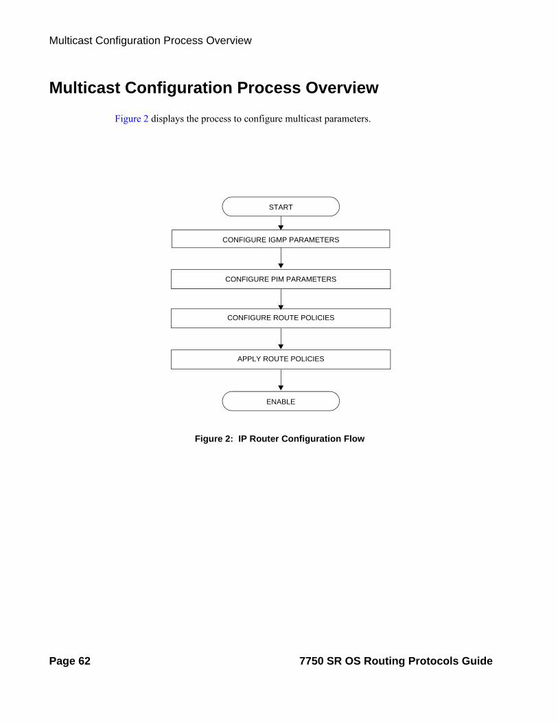
Multicast Configuration Process Overview
Figure 2: IP Router Configuration Flow
Multicast Configuration Process Overview
Figure 2 displays the process to configure multicast parameters.
ENABLE
START
CONFIGURE IGMP PARAMETERS
CONFIGURE PIM PARAMETERS
CONFIGURE ROUTE POLICIES
APPLY ROUTE POLICIES
Page 62 7750 SR OS Routing Protocols Guide

Multicast
Configuration Notes
This section describes multicast configuration caveats.
General
• A multicast stream is required by one of more multicast clients.
• A multicast stream is offered by one or more multicast servers.
7750 SR OS Routing Protocols Guide Page 63

Configuration Notes
Page 64 7750 SR OS Routing Protocols Guide

Multicast
Configuring Multicast Parameters with CLI
This section provides information to configure multicast, IGMP, and PIM.
Topics in this section include:
• Multicast Configuration Overview on page 66
• Basic Configuration on page 67
• Common Configuration Tasks on page 70
• Service Management Tasks on page 87
7750 SR OS Routing Protocols Guide Page 65

Multicast Configuration Overview
Multicast Configuration Overview
7750 SR routers use IGMP to manage membership for a given multicast session. IGMP is not enabled by default. When enabled, at least one interface must be specified in the IGMP context as IGMP is an interface function. Creating an interface enables IGMP. Traffic can only flow away from the router to an IGMP interface and to and from a PIM interface. A router directly connected to a source must have PIM enabled on the interface to that source. The traffic travels in a network from PIM interface to PIM interface and arrives finally on an IGMP enabled interface.
The IGMP CLI context allows you to specify an existing IP interface and modify the interface-specific parameters. Static IGMP group memberships can be configured to test multicast forwarding without a receiver host. When IGMP static group membership is enabled, data is forwarded to an interface without receiving membership reports from host members.
When static IGMP group entries on point-to-point links that connect routers to a rendezvous point (RP) are configured, the static IGMP group entries do not generate join messages toward the RP. When a host wants to receive multicast sessions it sends a join message for each multicast group it wants to join. Then, a leave message may be sent for each multicast group it no longer wishes to participate with.
A multicast router keeps a list of multicast group memberships for each attached network, and an interval timer for each membership. Hosts issue a Multicast Group Membership Report when they want to receive a multicast session. The reports are sent to all multicast routers.
PIM is not enabled by default. When PIM is enabled, data is forwarded to network segments with active receivers that have explicitly requested the multicast group. When enabled, at least one interface must be specified in the PIM context as PIM is an interface function. Creating an interface enables PIM.
Page 66 7750 SR OS Routing Protocols Guide

Multicast
Basic Configuration
Perform the following basic multicast configuration tasks:
For IGMP:
• Enable IGMP (required)
• Configure IGMP interfaces (required)
• Specify IGMP version on the interface (optional)
• Configure static (S,G)/(*,G) (optional)
• Configure SSM translation (optional)
For PIM:
• Enable PIM (required)
• Add interfaces so the protocol establishes adjacencies with the neighboring routers (required)
• Configure a way to calculate group-to-RP mapping (required) by either:
Static group-to-RP mapping
Enable Candidate RP/Bootstrap mechanism on some routers.
• Enable unicast routing protocols to learn routes towards the RP/source for reverse path forwarding (required)
• Add SSM ranges (optional)
• Enable Candidate BSR (optional)
• Enable Candidate RP (optional)
• Change hello interval (optional)
• Configure route policies (bootstrap-export, bootstrap-import, import join and register)
For MSDP:
• Enable MSDP (required)
• Configure peer
• Configure local address
For MCAC:
• Configure policy name
• Configure bundle parameters
• Specify default action
7750 SR OS Routing Protocols Guide Page 67

Basic Configuration
The following example displays the enabled IGMP and PIM configurations:
A:LAX>config>router>igmp# info---------------------------------------------- interface "lax-vls" exit interface "p1-ix" exit----------------------------------------------A:LAX>config>router>igmp# info detail---------------------------------------------- interface "lax-vls" no import version 3 no shutdown exit interface "p1-ix" no import version 3 no shutdown exit query-interval 125 query-last-member-interval 1 query-response-interval 10 robust-count 2 no shutdown----------------------------------------------A:LAX>config>router>igmp# exitA:LAX>config>router# pimA:LAX>config>router>pim# info---------------------------------------------- interface "system" exit interface "lax-vls" exit interface "lax-sjc" exit interface "p1-ix" exit rp static address 2.22.187.237 group-prefix 224.24.24.24/32 exit exit bsr-candidate shutdown exit rp-candidate shutdown exit exit----------------------------------------------A:LAX>config>router>pim# info detail---------------------------------------------- no import join-policy no import register-policy interface "system"
Page 68 7750 SR OS Routing Protocols Guide

Multicast
priority 1 hello-interval 30 multicast-senders auto no tracking-support bsm-check-rtr-alert no shutdown exit interface "lax-vls" priority 1 hello-interval 30 multicast-senders auto no tracking-support bsm-check-rtr-alert no shutdown exit interface "lax-sjc" priority 1 hello-interval 30 multicast-senders auto no tracking-support bsm-check-rtr-alert no shutdown exit interface "p1-ix" priority 1 hello-interval 30 multicast-senders auto no tracking-support bsm-check-rtr-alert no shutdown exit apply-to none rp no bootstrap-import no bootstrap-export static address 2.22.187.237 no override group-prefix 224.24.24.24/32 exit exit bsr-candidate shutdown priority 0 hash-mask-len 30 no address exit rp-candidate shutdown no address holdtime 150 priority 192 exit exit no shutdown----------------------------------------------A:LAX>config>router>pim#
7750 SR OS Routing Protocols Guide Page 69

Common Configuration Tasks
Common Configuration Tasks
The following sections describe basic multicast configuration tasks.
• Configuring IGMP Parameters on page 70
Enabling IGMP on page 70
Configuring an IGMP Interface on page 71
Configuring Static Parameters on page 72
Configuring SSM Translation on page 74
• Configuring PIM Parameters on page 75
Enabling PIM on page 75
Configuring PIM Interface Parameters on page 76
Importing PIM Join/Register Policies on page 81
• Configuring Multicast Source Discovery Protocol (MSDP) Parameters on page 83
• Configuring MCAC Parameters on page 84
• Disabling IGMP or PIM on page 87
Configuring IGMP Parameters
Enabling IGMP
Use the following CLI syntax to enable IGMP.
CLI Syntax: config>router# igmp
The following example displays the detailed output when IGMP is enabled.
A:LAX>>config>router# info detail...#------------------------------------------echo "IGMP Configuration"#------------------------------------------ igmp query-interval 125 query-last-member-interval 1 query-response-interval 10 robust-count 2 no shutdown exit#------------------------------------------A:LAX>>config>system#
Page 70 7750 SR OS Routing Protocols Guide

Multicast
Configuring an IGMP Interface
To configure an IGMP interface:
CLI Syntax: config>router# igmpinterface ip-int-name
max-groups valueimport policy-nameversion versionno shutdown
Use the following CLI syntax to configure IGMP interfaces:
Example: config>router#config>router>igmp# interface "lax-vls" config>router>igmp>if? no shutdownconfig>router>igmp>if# exitconfig>router>igmp# interface "p1-ix" config>router>igmp>if? no shutdownconfig>router>igmp>if# exitconfig>router>igmp# interface "lax-sjc" config>router>igmp>if? no shutdownconfig>router>igmp>if# exit
The following example displays the IGMP configuration:
A:LAX>config>router>igmp# info---------------------------------------------- interface "lax-sjc" exit interface "lax-vls" exit interface "p1-ix" exit----------------------------------------------A:LAX>config>router>igmp# exit
7750 SR OS Routing Protocols Guide Page 71

Common Configuration Tasks
Configuring Static Parameters
To add an IGMP static multicast source:
CLI Syntax: config>router# igmpinterface ip-int-name
no shutdownstatic
group grp-ip-addresssource ip-address
Use the following CLI syntax to configure static group addresses and source addresses for the SSM translate group ranges:
Example: config>router>igmp# interface lax-vlsconfig>router>igmp>if# staticconfig>router>igmp>if>static# group 229.255.0.2config>router>igmp>if>static>group# source 172.22.184.197config>router>igmp>if>static>group# exitconfig>router>igmp>if>static# exitconfig>router>igmp>if# exit
The following example displays the configuration:
A:LAX>config>router>igmp# info---------------------------------------------- interface "lax-sjc" exit interface "lax-vls" static group 229.255.0.2 source 172.22.184.197 exit exit exit interface "p1-ix" exit----------------------------------------------A:LAX>config>router>igmp#
Page 72 7750 SR OS Routing Protocols Guide

Multicast
To add an IGMP static starg entry:
CLI Syntax: config>router# igmpinterface ip-int-name
no shutdownstatic
group grp-ip-addressstarg
Use the following CLI syntax to configure static group addresses and add a static (*,G) entry:
Example: config>router>igmp# interface lax-sjcconfig>router>igmp>if# staticconfig>router>igmp>if>static# group 230.1.1.1config>router>igmp>if>static>group# stargconfig>router>igmp>if>static>group# exitconfig>router>igmp>if>static# exitconfig>router>igmp>if# exitconfig>router>igmp#
The following example displays the configuration:
A:LAX>config>router>igmp# info---------------------------------------------- interface "lax-sjc" static group 230.1.1.1 starg exit exit exit interface "lax-vls" static group 229.255.0.2 source 172.22.184.197 exit exit exit interface "p1-ix" exit----------------------------------------------A:LAX>config>router>igmp#
7750 SR OS Routing Protocols Guide Page 73

Common Configuration Tasks
Configuring SSM Translation
To configure IGMP parameters:
CLI Syntax: config>router# igmpssm-translate
grp-range start endsource ip-address
The following example displays the command usage to configure IGMP parameters:
Example: config>router# igmpconfig>router>igmp# ssm-translateconfig>router>igmp>ssm# grp-range 229.255.0.1 231.2.2.2config>router>igmp>ssm>grp-range# source 10.1.1.1
The following example displays the SSM translation configuration:
A:LAX>config>router>igmp# info---------------------------------------------- ssm-translate grp-range 229.255.0.1 231.2.2.2 source 10.1.1.1 exit exit interface "lax-sjc" static group 230.1.1.1 starg exit exit exit interface "lax-vls" static group 229.255.0.2 source 172.22.184.197 exit exit exit interface "p1-ix" exit----------------------------------------------A:LAX>config>router>igmp# exit
Page 74 7750 SR OS Routing Protocols Guide

Multicast
Configuring PIM Parameters
• Enabling PIM on page 75
• Configuring PIM Interface Parameters on page 76
• Importing PIM Join/Register Policies on page 81
Enabling PIM
When configuring PIM, make sure to enable PIM on all interfaces for the routing instance, otherwise multicast routing errors can occur.
Use the following CLI syntax to enable PIM.
CLI Syntax:config>router# pim
The following example displays the detailed output when PIM is enabled.
A:LAX>>config>router# info detail...#------------------------------------------echo "PIM Configuration"#------------------------------------------ pim no import join-policy no import register-policy apply-to none rp no bootstrap-import no bootstrap-export static exit bsr-candidate shutdown priority 0 hash-mask-len 30 no address exit rp-candidate shutdown no address holdtime 150 priority 192 exit exit no shutdown exit#------------------------------------------...A:LAX>>config>system#
7750 SR OS Routing Protocols Guide Page 75

Common Configuration Tasks
Configuring PIM Interface Parameters
The following example displays the command usage to configure PIM interface parameters:
Example:A:LAX>config>router# pimA:LAX>config>router>pim# interface "system" A:LAX>config>router>pim>if# exitA:LAX>config>router>pim# interface "lax-vls" A:LAX>config>router>pim>if# exitA:LAX>config>router>pim# interface "lax-sjc" A:LAX>config>router>pim>if# exitA:LAX>config>router>pim# interface "p1-ix" A:LAX>config>router>pim>if# exitA:LAX>config>router>pim# rpA:LAX>config>router>pim>rp# staticA:LAX>config>router>pim>rp>static# address 2.22.187.237A:LAX>config>router>..>address# group-prefix 224.24.24.24/32A:LAX>config>router>pim>rp>static>address# exitA:LAX>config>router>pim>rp>static# exitA:LAX>config>router>pim>rp# exitA:LAX>config>router>pim#
The following example displays the PIM configuration:
A:LAX>config>router>pim# info---------------------------------------------- interface "system" exit interface "lax-vls" exit interface "lax-sjc" exit interface "p1-ix" exit rp static address 2.22.187.237 group-prefix 224.24.24.24/32 exit address 10.10.10.10 exit exit bsr-candidate shutdown exit rp-candidate shutdown exit exit----------------------------------------------A:LAX>config>router>pim#
Page 76 7750 SR OS Routing Protocols Guide

Multicast
Example:A:SJC>config>router# pimA:SJC>config>router>pim# interface "system" A:SJC>config>router>pim>if# exitA:SJC>config>router>pim# interface "sjc-lax" A:SJC>config>router>pim>if# exitA:SJC>config>router>pim# interface "sjc-nyc" A:SJC>config>router>pim>if# exitA:SJC>config>router>pim# interface "sjc-sfo" A:SJC>config>router>pim>if# exitA:SJC>config>router>pim# rpA:SJC>config>router>pim>rp# staticA:SJC>config>router>pim>rp>static# address 2.22.187.237A:SJC>config>router>pim>rp>static>address# group-prefix
224.24.24.24/32A:SJC>config>router>pim>rp>static>address# exitA:SJC>config>router>pim>rp>static# exitA:SJC>config>router>pim>rp# exitA:SJC>config>router>pim#
A:SJC>config>router>pim# info---------------------------------------------- interface "system" exit interface "sjc-lax" exit interface "sjc-nyc" exit interface "sjc-sfo" exit rp static address 2.22.187.237 group-prefix 224.24.24.24/32 exit exit bsr-candidate shutdown exit rp-candidate shutdown exit exit----------------------------------------------A:SJC>config>router>pim#
7750 SR OS Routing Protocols Guide Page 77

Common Configuration Tasks
Example:A:MV>config>router# pimA:MV>config>router>pim# interface "system" A:MV>config>router>pim>if# exitA:MV>config>router>pim# interface "mv-sfo" A:MV>config>router>pim>if# exitA:MV>config>router>pim# interface "mv-v1c" A:MV>config>router>pim>if# exitA:MV>config>router>pim# interface "p3-ix" A:MV>config>router>pim>if# exitA:MV>config>router>pim# rpA:MV>config>router>pim>rp# staticA:MV>config>router>pim>rp>static# address 2.22.187.237A:MV>config>router>pim>rp>static>address# group-prefix
224.24.24.24/32A:MV>config>router>pim>rp>static>address# exitA:MV>config>router>pim>rp>static#A:MV>config>router>pim>rp# exitA:MV>config>router>pim#
A:MV>config>router>pim# info---------------------------------------------- interface "system" exit interface "mv-sfo" exit interface "mv-vlc" exit interface "p3-ix" exit rp static address 2.22.187.237 group-prefix 224.24.24.24/32 exit exit bsr-candidate address 2.22.187.236 no shutdown exit rp-candidate address 2.22.187.236 no shutdown exit exit----------------------------------------------A:MV>config>router>pim#
Page 78 7750 SR OS Routing Protocols Guide

Multicast
Example:A:SFO>config>router# pimA:SFO>config>router>pim# interface "system" A:SFO>config>router>pim>if# exitA:SFO>config>router>pim# interface "sfo-sfc" A:SFO>config>router>pim>if# exitA:SFO>config>router>pim# interface "sfo-was" A:SFO>config>router>pim>if# exitA:SFO>config>router>pim# interface "sfo-mv" A:SFO>config>router>pim>if# exitA:SFO>config>router>pim# rpA:SFO>config>router>pim>rp# staticA:SFO>config>router>pim>rp>static# address 2.22.187.237A:SFO>config>router>pim>rp>static>address# group-prefix
224.24.24.24/32A:SFO>config>router>pim>rp>static>address# exitA:SFO>config>router>pim>rp>static# exitA:SFO>config>router>pim>rp # exitA:SFO>config>router>pim#
A:SFO>config>router>pim# info---------------------------------------------- interface "system" exit interface "sfo-sjc" exit interface "sfo-was" exit interface "sfo-mv" exit rp static address 2.22.187.237 group-prefix 224.24.24.24/32 exit exit bsr-candidate address 2.22.187.239 no shutdown exit rp-candidate address 2.22.187.239 no shutdown exit exit----------------------------------------------A:SFO>config>router>pim#
7750 SR OS Routing Protocols Guide Page 79

Common Configuration Tasks
Example:A:WAS>config>router# pimA:WAS>config>router>pim# interface "system" A:WAS>config>router>pim>if# exitA:WAS>config>router>pim# interface "was-sfo" A:WAS>config>router>pim>if# exitA:WAS>config>router>pim# interface "was-vlc" A:WAS>config>router>pim>if# exitA:WAS>config>router>pim# interface "p4-ix" A:WAS>config>router>pim>if# exitA:WAS>config>router>pim# rpA:WAS>config>router>pim>rp# staticA:WAS>config>router>pim>rp>static# address 2.22.187.237A:WAS>config>router>pim>rp>static>address# group-prefix
224.24.24.24/32A:WAS>config>router>pim>rp>static>address# exitA:WAS>config>router>pim>rp>static# exitA:WAS>config>router>pim>rp# bsr-candidateA:WAS>config>router>pim>rp>bsr-cand# address 2.22.187.240A:WAS>config>router>pim>rp>bsr-cand# no shutdownA:WAS>config>router>pim>rp>bsr-cand# exitA:WAS>config>router>pim>rp# exitA:WAS>config>router>pim#
A:WAS>config>router>pim# info---------------------------------------------- interface "system" exit interface "was-sfo" exit interface "was-vlc" exit interface "p4-ix" exit rp static address 2.22.187.237 group-prefix 224.24.24.24/32 exit exit bsr-candidate address 2.22.187.240 no shutdown exit rp-candidate address 2.22.187.240 no shutdown exit exit----------------------------------------------A:WAS>config>router>pim#
Page 80 7750 SR OS Routing Protocols Guide

Multicast
Importing PIM Join/Register Policies
The import command provides a mechanism to control the (*,G) and (S,G) state that gets created on a router. Import policies are defined in the config>router>policy-options context.
Note, in the import policy, if an action is not specified in the entry then the default-action takes precedence. If no entry matches then the default-action also takes precedence. If no default-action is specified, then the default default-action is executed.
Use the following commands to configure PIM parameters:
CLI Syntax: config>router# pim import {join-policy|register-policy} [policy-name [.. policy-name]
The following example displays the command usage to apply the policy statement which does not allow join messages for group 229.50.50.208/32 and source 192.168.0.0/16 but allows join messages for 192.168.0.0/16, 229.50.50.208 (see Configuring Route Policy Components on page 758):
Example: config>router# pimconfig>router>pim# import join-policy "foo"config>router>pim# no shutdown
The following example displays the PIM configuration:
A:LAX>config>router>pim# info---------------------------------------------- import join-policy "foo" interface "system" exit interface "lax-vls" exit interface "lax-sjc" exit interface "p1-ix" exit rp static address 2.22.187.237 group-prefix 224.24.24.24/3 exit address 10.10.10.10 exit exit bsr-candidate shutdown
7750 SR OS Routing Protocols Guide Page 81

Common Configuration Tasks
exit rp-candidate shutdown exit exit----------------------------------------------A:LAX>config>router>pim#
Page 82 7750 SR OS Routing Protocols Guide

Multicast
Configuring Multicast Source Discovery Protocol (MSDP) Parameters
Use the following commands to configure basic MSDP parameters:
CLI Syntax: config>router# msdppeer ip-address
active-source-limit numberauthentication-key [authentication-key|hash-key] [hash|hash2]default-peerexport policy-name [policy-name...(up to 5 max)]import policy-name [policy-name...(up to 5 max)]local-address ip-addressreceive-msdp-msg-rate number intervalseconds [threshold threshold]no shutdown
no shutdown
Use the following CLI syntax to configure MSDP parameters.
Example: config>router>msdp# peer 10.20.1.1config>router>msdp>peer# local-address 10.20.1.6config>router>msdp>peer# no shutdownconfig>router>msdp>peer# exitconfig>router>msdp# no shutdownconfig>router>msdp#
The following example displays the MSDP configuration:
ALA-48>config>router>msdp# info------------------------------------------- peer 10.20.1.1 local-address 10.20.1.6 exit-------------------------------------------ALA-48>config>router>msdp#
7750 SR OS Routing Protocols Guide Page 83

Common Configuration Tasks
Configuring MCAC Parameters
The MCAC policies can be added to a SAP, spoke SDP, mesh SDP, an IGMP interface, and a PIM interface.
The following example displays the command usage to create MCAC policies.
Example: config>router# mcacconfig>router>mcac# policy "btv_fr"config>router>mcac>policy# description "foreign TV offering"config>router>mcac>policy# bundle "FOR" createconfig>router>mcac>policy>bundle# bandwidth 30000config>router>mcac>policy>bundle# channel 224.0.3.1 224.0.3.1 bw 4000config>router>mcac>policy>bundle# channel 224.0.3.2 224.0.3.2 bw 4000config>router>mcac>policy>bundle# channel 224.0.4.1 224.0.4.1 bw 3500 class high type man-datoryconfig>router>mcac>policy>bundle# channel 224.0.4.2 224.0.4.2 bw 3500 class highconfig>router>mcac>policy>bundle# channel 224.0.4.3 224.0.4.3 bw 2800 type mandatoryconfig>router>mcac>policy>bundle# channel 224.0.4.4 224.0.4.4 bw 2800config>router>mcac>policy>bundle# mc-constraintsconfig>router>mcac>policy>bundle>mc-constraints# level 1 bw 20000config>router>mcac>policy>bundle>mc-constraints# level 2 bw 20000config>router>mcac>policy>bundle>mc-constraints# level 3 bw 20000config>router>mcac>policy>bundle>mc-constraints# level 4 bw 20000config>router>mcac>policy>bundle>mc-constraints# level 5 bw 20000config>router>mcac>policy>bundle>mc-constraints# level 6 bw 20000 config>router>mcac>pol-icy>bundle>mc-constraints# lag-port-down 1 number-down 1 level 1config>router>mcac>policy>bundle>mc-constraints# lag-port-down 1 number-down 2 level 3config>router>mcac>policy>bundle>mc-constraints# lag-port-down 1 number-down 3 level 5config>router>mcac>policy>bundle>mc-constraints# lag-port-down 2 number-down 1 level 1config>router>mcac>policy>bundle>mc-constraints# lag-port-down 2 number-down 2 level 3config>router>mcac>policy>bundle>mc-constraints# lag-port-down 2 number-down 3 level 5config>router>mcac>policy>bundle>mc-constraints# exitconfig>router>mcac>policy>bundle# no shutdownconfig>router>mcac>policy>bundle# exitconfig>router>mcac>policy# exitconfig>router>mcac# policy "btv_vl"config>router>mcac>policy# description "eastern TV offering"config>router>mcac>policy# bundle "VRT" createconfig>router>mcac>policy>bundle# bandwidth 120000config>router>mcac>policy>bundle# channel 224.1.2.0 224.1.2.4 bw 4000class high type manda-toryconfig>router>mcac>policy>bundle# channel 224.1.2.5 224.1.2.5 bw 20000 type mandatoryconfig>router>mcac>policy>bundle# channel 224.1.2.10 224.1.2.10 bw 8000 type mandatoryconfig>router>mcac>policy>bundle# channel 224.2.2.0 224.2.2.4 bw 4000config>router>mcac>policy>bundle# channel 224.2.2.5 224.2.2.5 bw 10000 class highconfig>router>mcac>policy>bundle# channel 224.2.2.6 224.2.2.6 bw 10000 class highconfig>router>mcac>policy>bundle# channel 224.2.2.7 224.2.2.7 bw 10000config>router>mcac>policy>bundle# channel 224.2.2.8 224.2.2.8 bw 10000config>router>mcac>policy>bundle# mc-constraintsconfig>router>mcac>policy>bundle>mc-constraints# level 1 bw 60000config>router>mcac>policy>bundle>mc-constraints# level 2 bw 50000config>router>mcac>policy>bundle>mc-constraints# level 3 bw 40000config>router>mcac>policy>bundle>mc-constraints# level 4 bw 30000config>router>mcac>policy>bundle>mc-constraints# level 5 bw 20000config>router>mcac>policy>bundle>mc-constraints# level 6 bw 10000
Page 84 7750 SR OS Routing Protocols Guide

Multicast
config>router>mcac>policy>bundle>mc-constraints# lag-port-down 1 number-down 1 level 1config>router>mcac>policy>bundle>mc-constraints# lag-port-down 1 number-down 2 level 3config>router>mcac>policy>bundle>mc-constraints# lag-port-down 1 number-down 3 level 5config>router>mcac>policy>bundle>mc-constraints# lag-port-down 2 number-down 1 level 1config>router>mcac>policy>bundle>mc-constraints# lag-port-down 2 number-down 2 level 3config>router>mcac>policy>bundle>mc-constraints# lag-port-down 2 number-down 3 level 5config>router>mcac>policy>bundle>mc-constraints# exitconfig>router>mcac>policy>bundle# no shutdownconfig>router>mcac>policy>bundle# exitconfig>router>mcac>policy# exit
The following example displays the configuration:
*A:ALA-48>config>router>mcac# info---------------------------------------------- policy "btv_fr" description "foreign TV offering" bundle "FOR" create bandwidth 30000 channel 224.0.3.1 224.0.3.1 bw 4000 channel 224.0.3.2 224.0.3.2 bw 4000 channel 224.0.4.1 224.0.4.1 bw 3500 class high type mandatory channel 224.0.4.2 224.0.4.2 bw 3500 class high channel 224.0.4.3 224.0.4.3 bw 2800 type mandatory channel 224.0.4.4 224.0.4.4 bw 2800 mc-constraints level 1 bw 20000 level 2 bw 20000 level 3 bw 20000 level 4 bw 20000 level 5 bw 20000 level 6 bw 20000 lag-port-down 1 number-down 1 level 1 lag-port-down 1 number-down 2 level 3 lag-port-down 1 number-down 3 level 5 lag-port-down 2 number-down 1 level 1 lag-port-down 2 number-down 2 level 3 lag-port-down 2 number-down 3 level 5 exit no shutdown exit exit policy "btv_vl" description "eastern TV offering" bundle "VRT" create bandwidth 120000 channel 224.1.2.0 224.1.2.4 bw 4000 class high type mandatory channel 224.1.2.5 224.1.2.5 bw 20000 type mandatory channel 224.1.2.10 224.1.2.10 bw 8000 type mandatory channel 224.2.2.0 224.2.2.4 bw 4000 channel 224.2.2.5 224.2.2.5 bw 10000 class high channel 224.2.2.6 224.2.2.6 bw 10000 class high channel 224.2.2.7 224.2.2.7 bw 10000 channel 224.2.2.8 224.2.2.8 bw 10000 mc-constraints level 1 bw 60000 level 2 bw 50000
7750 SR OS Routing Protocols Guide Page 85

Common Configuration Tasks
level 3 bw 40000 level 4 bw 30000 level 5 bw 20000 level 6 bw 10000 lag-port-down 1 number-down 1 level 1 lag-port-down 1 number-down 2 level 3 lag-port-down 1 number-down 3 level 5 lag-port-down 2 number-down 1 level 1 lag-port-down 2 number-down 2 level 3 lag-port-down 2 number-down 3 level 5 exit no shutdown exit exit----------------------------------------------*A:ALA-48>config>router>mcac#
Page 86 7750 SR OS Routing Protocols Guide

Multicast
Service Management Tasks
This section discusses the following service management tasks:
• Disabling IGMP or PIM on page 87
Disabling IGMP or PIM
Use the following CLI syntax to disable IGMP and PIM:
CLI Syntax: config>router# igmp
shutdownmsdp
shutdownpim
shutdown
The following example displays the command usage to disable multicast:
Example: config>router# igmpconfig>router>igmp# shutdownconfig>router>igmp# exitconfig>router#config>router>msdp# shutdownconfig>router>msdp# exitconfig>router# pimconfig>router>pim# shutdownconfig>router>pim# exit
7750 SR OS Routing Protocols Guide Page 87

Service Management Tasks
The following example displays the configuration output:
A:LAX>config>router# info----------------------------------------------...#------------------------------------------echo "IGMP Configuration"#------------------------------------------ igmp shutdown ssm-translate grp-range 229.255.0.1 231.2.2.2 source 10.1.1.1 exit exit interface "lax-sjc" static group 230.1.1.1 starg exit exit exit interface "lax-vls" static group 229.255.0.2 source 172.22.184.197 exit exit exit interface "p1-ix" exit exit#------------------------------------------
#--------------------------------------------------echo "MSDP Configuration"#-------------------------------------------------- msdp shutdown peer 10.20.1.1 local-address 10.20.1.6 exit group "test" active-source-limit 50000 receive-msdp-msg-rate 100 interval 300 threshold 5000 export "LDP-export" import "LDP-import" local-address 10.10.10.103 mode mesh-group peer 10.10.10.104 exit exit exit#--------------------------------------------------
echo "PIM Configuration"#------------------------------------------ pim
Page 88 7750 SR OS Routing Protocols Guide

Multicast
shutdown import join-policy "foo" interface "system" exit interface "lax-sjc" exit interface "lax-vls" exit interface "p1-ix" exit rp static address 2.22.187.237 group-prefix 224.24.24.24/32 exit address 10.10.10.10 exit exit bsr-candidate shutdown exit rp-candidate shutdown exit exit exit#------------------------------------------....------------------------------------------A:LAX>config>router#
7750 SR OS Routing Protocols Guide Page 89

Service Management Tasks
Page 90 7750 SR OS Routing Protocols Guide

Multicast
Multicast Command Reference
Command Hierarchies• Configuration Commands on page 91
IGMP Commands on page 91
PIM Commands on page 93
MSDP Commands on page 96
Multicast CAC Policy Commands on page 98
• Operational Commands on page 100
• Show Commands on page 100
• Clear Commands on page 101
• Debug Commands on page 103
Configuration Commands
config— router
— [no] ip-fast-reroute— mc-maximum-routes number [log-only] [threshold threshold]— no mc-maximum-routes— multicast-info policy-name— no multicast-info
IGMP Commands
config— router
— [no] igmp— [no] interface ip-int-name
— [no] disable-router-alert-check — [no] group-interface ip-int-name
— [no] shutdown— import policy-name— no import— max-groups value— no max-groups— mcac
— mc-constraints— level level-id bw bandwidth— no level level-id— number-down number-lag-port-down level level-id— no number-down number-lag-port-down— [no] shutdown
— policy mcac-policy-name— no policy
7750 SR OS Routing Protocols Guide Page 91

Multicast Command Reference
— unconstrained-bw bandwidth mandatory-bw mandatory-bw— no unconstrained-bw
— [no] shutdown— ssm-translate
— [no] grp-range start end— [no] source ip-address
— static— [no] group grp-ip-address
— [no] source ip-address— [no] starg
— [no] subnet-check— version version— no version
— query-interval seconds— no query-interval— query-last-member-interval seconds— no query-last-member-interval— query-response-interval seconds— no query-response-interval— robust-count robust-count— no robust-count— [no] shutdown— ssm-translate
— [no] grp-range start end— [no] source ip-address
— [no] tunnel-interface rsvp-p2mp lsp-name — static
— [no] group grp-ip-address— [no] source ip-address— [no] starg
Page 92 7750 SR OS Routing Protocols Guide

Multicast
PIM Commands
config— router
— [no] pim— apply-to {ies | non-ies | all | none}— [no] enable-mdt-spt— import {join-policy | register-policy} policy-name [.. policy-name]— no import {join-policy | register-policy}— [no] interface ip-int-name
— assert-period assert-period— no assert-period— [no] bfd-enable [ipv4 | ipv6]— [no] bsm-check-rtr-alert— hello-interval hello-interval— no hello-interval— hello-multiplier deci-units— no hello-multiplier— [no] improved-assert— [no] ipv4-multicast-disable— [no] ipv6-multicast-disable— max-groups value— no max-groups— mcac
— mc-constraints— level level bw bandwidth— no level level— number-down number-lag-port-down level level-id— no number-down number-lag-port-down— [no] shutdown
— policy policy-name— no policy— unconstrained-bw bandwidth mandatory-bw mandatory-bw— no unconstrained-bw
— multicast-senders {auto | always | never}— no multicast-senders— no p2mp-ldp-tree-join— priority dr-priority— no priority— [no] shutdown— sticky-dr [priority dr-priority]— no sticky-dr— three-way-hello [compatibility-mode]— no three-way-hello— [no] tracking-support
— [no] ipv4-multicast-disable— ipv6-multicast-disable— [no] lag-usage-optimization— [no] mc-ecmp-balance— mc-ecmp-balance-hold minutes— no mc-ecmp-balance-hold— [no] mc-ecmp-hashing-enabled— [no] non-dr-attract-traffic— rp
— [no] anycast rp-ip-address
7750 SR OS Routing Protocols Guide Page 93

Multicast Command Reference
— [no] rp-set-peer ip-address— [no] auto-rp-discovery— bootstrap-export policy-name [.. policy-name]— no bootstrap-export— bootstrap-import policy-name [.. policy-name]— no bootstrap-import— bsr-candidate
— address ip-address— no address— hash-mask-len hash-mask-length— no hash-mask-len— priority bootstrap-priority— no priority— [no] shutdown
— ipv6— [no] anycast rp-ip-address
— [no] rp-set-peer ip-address— bsr-candidate
— address ip-address— no address— hash-mask-len hash-mask-length— no hash-mask-len— priority bootstrap-priority— no priority— [no] shutdown
— [no] embedded-rp— [no] group-range ipv6-address/prefix-length— [no] shutdown
— rp-candidate— address ip-address— no address— [no] group-range {grp-ip-address/mask | grp-ip-
address netmask}— holdtime holdtime— no holdtime— priority priority— no priority— [no] shutdown
— static— [no] address ip-address
—[no] group-prefix {grp-ip-address/mask | grp-ip-address netmask}
—[no] override— rp-candidate
— address ip-address— no address— [no] group-range {grp-ip-address/mask | grp-ip-address net-
mask}— holdtime holdtime— no holdtime— priority priority— no priority— [no] shutdown
— static— [no] address ip-address
Page 94 7750 SR OS Routing Protocols Guide

Multicast
— [no] group-prefix {grp-ip-address/mask | grp-ip-address netmask}
— [no] override— [no] rpf6-table {rtable6-m | rtable6-u | both}— [no] shutdown— spt-switchover-threshold {grp-ip-address/mask | grp-ip-address netmask} spt-
threshold— no spt-switchover-threshold {grp-ip-address/mask | grp-ip-address netmask}— [no] ssm-groups
— [no] group-range {ip-prefix/mask | ip-prefix netmask}— [no] tunnel-interface {rsvp-p2mp lsp-name | ldp-p2mp p2mp-id} [sender ip-
address] | ldp-p2mp p2mp-id sender sender-address [root-node]}
7750 SR OS Routing Protocols Guide Page 95

Multicast Command Reference
MSDP Commands
config— router
— [no] msdp— [no] active-source-limit number — [no] data-encapsulation — export [policy-name...(up to 5 max)]— no export— [no] group group-name
— [no] active-source-limit number — export policy-name [policy-name...(up to 5 max)]— no export— import policy-name [policy-name...(up to 5 max)]— no import— local-address address— no local-address— mode {mesh-group | standard}— [no] peer peer-address
— [no] active-source-limit number — authentication-key [authentication-key | hash-key]
[hash|hash2]— no authentication-key— [no] default-peer— export policy-name [policy-name...(up to 5 max)]— no export— import policy-name [policy-name...(up to 5 max)]— no import— local-address address— no local-address— [no] shutdown
— receive-msdp-msg-rate number interval seconds [threshold number] — no receive-msdp-msg-rate— [no] shutdown
— import policy-name [policy-name...(up to 5 max)]— no import— local-address address— no local-address— [no] peer peer-address
— [no] active-source-limit number — authentication-key [authentication-key | hash-key] [hash | hash2]— no authentication-key— [no] default-peer— export policy-name[policy-name...(up to 5 max)]— no export— import policy-name[policy-name...(up to 5 max)]— no import— local-address address— no local-address— receive-msdp-msg-rate number interval seconds [threshold number] — no receive-msdp-msg-rate— [no] shutdown
— receive-msdp-msg-rate number interval seconds [threshold number] — no receive-msdp-msg-rate— rpf6-table {rtable-m | rtable-u | both}
Page 96 7750 SR OS Routing Protocols Guide

Multicast
— no rpf6-table— sa-timeout seconds— no sa-timeout— [no] shutdown— [no] source prefix/mask
— active-source-limit number — no active-source-limit number
7750 SR OS Routing Protocols Guide Page 97

Multicast Command Reference
Multicast CAC Policy Commands
config — [no] router
— mcac— [no] policy policy-name
— [no] bundle bundle-name — bandwidth bandwidth— no bandwidth— channel start-address end-address bw bandwidth [class {high
| low}] [type {mandatory | optional}]— no channel mc-ip-addr mc-ip-addr— description description-string— no description— mc-constraints
— lag-port-down lag-id number-down number-lag-port-down level level-id
— no lag-port-down lag-id number-down number-lag-port-down
— level level bw bandwidth— no level level
— [no] shutdown— default-action {accept | discard}— description description-string— no description
Page 98 7750 SR OS Routing Protocols Guide

Multicast
Multicast Listener Discovery (MLD) Commands
config — [no] router
— [no] mld— [no] interface ip-int-name
— import policy-name— no import— max-groups value— no max-groups— query-interval seconds— no query-interval— query-last-member-interval seconds— no query-last-member-interval— query-response-interval seconds— no query-response-interval— [no] shutdown— static
— [no] group grp-ipv6-address— [no] source src-ipv6-address— [no] starg
— version version— no version
— query-interval seconds— no query-interval— query-last-member-interval seconds— no query-last-member-interval— query-response-interval seconds— no query-response-interval— robust-count robust-count— no robust-count— [no] shutdown— ssm-translate
— [no] grp-range start end— [no] source src-ipv6-address
7750 SR OS Routing Protocols Guide Page 99

Multicast Command Reference
Operational Commands
<GLOBAL>
— mrinfo ip-address [router router-name | service] — mstat source ip-address [group grp-ip-address] [destination dst-ip-address] [hop hop] [router
router-name | service] [wait-time wait-time]— mtrace source ip-address [group grp-ip-address][destination dst-ip-address] [hop hop] [router
router-name | service] [wait-time wait-time]
Show Commands
show— router
— igmp— group [grp-ip-address]— group summary— hosts [group grp-address] [detail] [fwd-service service-id] [grp-interface ip-int-
name]— hosts [host ip-address] [group grp-address] [detail]— hosts summary— interface [ip-int-name | ip-address] [group] [grp-address] [detail]— ssm-translate— ssm-translate interface interface-name— static [ip-int-name | ip-addr]— statistics [ip-int-name | ip-address]— statistics host [ip-address]— status
show— router
— pim— anycast [detail]— crp [ip-address]— s-pmsi [data-mt-interface-name] [detail]— group [grp-ip-address] [source ip-address] [type {starstarrp|starg|sg}] [detail]
[family]— interface [ip-int-name | mt-int-name | ip-address] [group [grp-ip-address] source
ip-address] [type {starstarrp | starg | sg}] [detail] [family]— neighbor [ip-address | ip-int-name [address ip-address]] [detail] [family]— rp [ip-address]— rp-hash grp-ip-address— statistics [ip-int-name | mt-int-name | ip-address] [family]— status [detail] [family]
show— router
— mld— group [grp-ipv6-address]— interface [ip-int-name | ip-address] [group] [grp-ipv6-address] [detail]— ssm-translate— static [ip-int-name | ip-address]— statistics [ip-int-name | ipv6-address]— status
show— router
Page 100 7750 SR OS Routing Protocols Guide

Multicast
— msdp— group [group-name] [detail]— peer [ip-address] [group group-name] [detail]— source [ip-address/mask] [type {configured | dynamic | both}] [detail]— source-active [group ip-address | local | originator ip-address | peer ip-address |
source ip-address |{group ip-address source ip-address}][detail]— source-active-rejected [peer-group name] [group ip-address] [source ip-
address] [originator ip-address] [peer ip-address]— statistics [peer ip-address]— status
— mcac— policy [policy-name [bundle bundle-name] [protocol protocol-name] [interface
if-name] [detail]]— statistics
show— router {router-instance}
— mvpn
show— router
— tunnel-table [ip-address [/mask]] [protocol | sdp sdp-id]— tunnel-table [summary]
Clear Commands
clear— router
— igmp— database [interface ip-int-name|ip-address] group grp-ip-address [source src-ip-
address]— database grp-interface interface-name [fwd-service service-id]— database [interface ip-int-name|ip-address] group grp-ip-address source src-ip-
address— database host [ip-address]— database interface ip-int-name|ip-address [group grp-ip-address] [source src-ip-
address]— statistics [interface ip-int-name | ip-address]— version [interface ip-int-name | ip-address]
— mld— database [interface ip-int-name|ipv6-address] [group ip-address [source ip-
address]]— statistics [ip-int-name|ipv6-address]— version [ip-int-name | ip-address]
— msdp— cache [peer ip-address] [group ip-address] [source ip-address] [originrp ip-
address]— statistics [peer ip-address]
— pim— database [interface ip-int-name | ip-address | mt-int-name] [group grp-ip-address
[source ip-address]][family]]— neighbor [interface ip-int-name | ip-address] [family]— s-pmsi [mdSrcAddr] [mdGrpAddr] [vprnSrcAddr vprnGrpAddr]
7750 SR OS Routing Protocols Guide Page 101

Multicast Command Reference
— statistics [{[interface ip-int-name | ip-address | mt-int-name]} {[group grp-ip-address [source ip-address]]}][family]]
clear— service
— id— igmp-snooping
— port-db sap sap-id [group grp-address [source ip-address]]— port-db sdp sdp-id:vc-id [group grp-address [source ip-address]]— querier— statistics [all | sap sap-id | sdp sdp-id:vc-id
— pim-snooping— database [[sap sap-id | sdp sdp-id:vc-id] [group grp-ip-address]
[source src-ip-address]]— neighbor [ip-address | sap sap-id | sdp sdp-id:vc-id] — statistics [sap sap-id | sdp sdp-id:vc-id]
Page 102 7750 SR OS Routing Protocols Guide

Multicast
Debug Commands
debug— router
— igmp— [no] group-interface [fwd-service service-id] [ip-int-name]— host [ip-address]— host [fwd-service service-id] group-interface ip-int-name— no host [ip-address]— no host [fwd-service service-id] group-interface ip-int-name— [no] interface [ip-int-name | ip-address]— mcs [ip-int-name]— no mcs— [no] misc— packet [query|v1-report|v2-report|v3-report|v2-leave] host ip-address— no packet [query|v1-report|v2-report|v3-report|v2-leave] [ip-int-name|ip-
address]— no packet [query|v1-report|v2-report|v3-report|v2-leave] host ip-address— packet [query|v1-report|v2-report|v3-report|v2-leave] [ip-int-name|ip-address]
debug— router
— pim— [no] adjacency— all [group grp-ip-address] [source ip-address] [detail]— no all— assert [group grp-ip-address] [source ip-address] [detail]— no assert— bsr [detail]— no bsr— data [group grp-ip-address] [source ip-address] [detail]— no data— db [group grp-ip-address] [source ip-address] [detail]— no db— interface [ip-int-name | mt-int-name| ip-address] [detail]— no interface— jp [group grp-ip-address] [source ip-address] [detail]— no jp— mrib[group grp-ip-address] [source ip-address] [detail]— no mrib— msg [detail]— no msg— packet [hello | register | register-stop| jp | bsr | assert | crp] [ip-int-name | ip-
address]— no packet— register [group grp-ip-address] [source ip-address] [detail]— no register— rtm [detail]— no rtm— s-pmsi [{vpnSrcAddr [vpnGrpAddr]} [mdSrcAddr]] [detail]— no s-pmsi
debug— router
— [no] msdp— packet [pkt-type] [peer ip-address]— no packet
7750 SR OS Routing Protocols Guide Page 103

Multicast Command Reference
— pim [grp-address]— no pim— rtm [rp-address]— no rtm— sa-db [group grpAddr] [source srcAddr] [rp rpAddr]— no sa-db
Page 104 7750 SR OS Routing Protocols Guide

Multicast
Configuration Commands
Generic Commands
shutdown
Syntax [no] shutdown
Context config>router>igmpconfig>router>igmp>interfaceconfig>router>igmp>interface>group-interfaceconfig>router>igmp>if>mcac>mc-constraintsconfig>router>pimconfig>router>pim>interface ip-int-nameconfig>router>pim>rp>rp-candidateconfig>router>pim>rp>bsr-candidateconfig>router>pim>rp>ipv6>rp-candidateconfig>router>pim>rp>ipv6>bsr-candidateconfig>router>pim>if>mcac>mc-constraintsconfig>router>msdpconfig>router>msdp>peerconfig>router>msdp>groupconfig>router>mcac>policy>bundleconfig>router>mldconfig>router>mld>interface
Description The shutdown command administratively disables the entity. When disabled, an entity does not change, reset, or remove any configuration settings or statistics. Many entities must be explicitly enabled using the no shutdown command.
The shutdown command administratively disables an entity. The operational state of the entity is disabled as well as the operational state of any entities contained within. Many objects must be shut down before they may be deleted.
Unlike other commands and parameters where the default state is not indicated in the configuration file, shutdown and no shutdown are always indicated in system generated configuration files.
The no form of the command puts an entity into the administratively enabled state.
Default no shutdown: config>router>igmpconfig>router>igmp>interface ip-int-nameconfig>router>pimconfig>router>pim>rp>rp-candidate
shutdown: config>router>pim>rp>bsr-candidate
7750 SR OS Routing Protocols Guide Page 105

Configuration Commands
ssm-translate
Syntax ssm-translate
Context config>router>igmp>interface>shutdown
Description This command adds or removes ssm-translate group ranges.
source
Syntax [no] source ip-address
Context config>router>igmp>interface>shutdown>ssm-translate>grp-range
Description This command adds or removes source addresses for the SSM translate group range.
Parameters ip-address — a.b.c.d - unicast source address
grp-range
Syntax [no] grp-range start end
Context config>router>igmp>interface>shutdown>ssm-translate
Description This command adds or removes SSM translate group range entries.
Parameters start — a.b.c.d - multicast group range start address
end — a.b.c.d - multicast group range end address
description
Syntax description description-stringno description
Context config>router>mcac>policyconfig>router>mcac>policy>bundle
Description This command creates a text description stored in the configuration file for a configuration context.
The description command associates a text string with a configuration context to help identify the context in the configuration file.
The no form of the command removes any description string from the context.
Default No description associated with the configuration context.
Parameters string — The description character string. Allowed values are any string up to 80 characters long composed of printable, 7-bit ASCII characters. If the string contains special characters (#, $, spaces, etc.), the entire string must be enclosed within double quotes.
Page 106 7750 SR OS Routing Protocols Guide

Multicast
ip-fast-reroute
Syntax [no] ip-fast-reroute
Context config>router
Description This command configures IP fast reroute.
mc-maximum-routes
Syntax mc-maximum-routes number [log-only] [threshold threshold]no mc-maximum-routes
Context config>router
Description This command specifies the maximum number of multicast routes that can be held within a VPN routing/forwarding (VRF) context. When this limit is reached, a log and SNMP trap are sent. If the log-only parameter is not specified and the maximum-routes value is set below the existing number of routes in a VRF, then no new joins will be processed.
The no form of the command disables the limit of multicast routes within a VRF context. Issue the no form of the command only when the VPRN instance is shutdown.
Default no mc-maximum-routes
Parameters number — Specifies the maximum number of routes to be held in a VRF context.
Values 1 — 2147483647
log-only — Specifies that if the maximum limit is reached, only log the event. log-only does not disable the learning of new routes.
threshold threshold — The percentage at which a warning log message and SNMP trap should be sent.
Values 0 — 100
Default 1
multicast-info
Syntax multicast-info-policy policy-nameno multicast-info-policy
Context configure>router
Description This command configures multicast information policy.
Parameters policy-name — Specifies the policy name.
Values 32 chars max
7750 SR OS Routing Protocols Guide Page 107

Configuration Commands
Router IGMP Commands
igmp
Syntax [no] igmp
Context config>router
Description This command enables the Internet Group Management Protocol (IGMP) context. When the context is created, the IGMP protocol is enabled.
The Internet Group Management Protocol (IGMP) is used by IPv4 systems (hosts and routers) to report their IP multicast group memberships to neighboring multicast routers. An IP multicast router can be a member of one or more multicast groups, in which case it performs both the “multicast router part” of the protocol which collects the membership information needed by its multicast routing protocol, and the “group member part” of the protocol which informs itself and other neighboring multicast routers of its memberships.
The no form of the command disables the IGMP instance. To start or suspend execution of IGMP without affecting the configuration, use the no shutdown command.
Default none
interface
Syntax [no] interface ip-int-name
Context config>router>igmp
Description This command enables the context to configure an IGMP interface. The interface is a local identifier of the network interface on which reception of the specified multicast address is to be enabled or disabled.
The no form of the command deletes the IGMP interface. The shutdown command in the config>router>igmp>interface context can be used to disable an interface without removing the configuration for the interface.
Default no interface — No interfaces are defined.
Parameters ip-int-name — The IP interface name. Interface names must be unique within the group of defined IP interfaces for config router interface and config service ies interface commands. An interface name cannot be in the form of an IP address. Interface names can be any string up to 32 characters long composed of printable, 7-bit ASCII characters. If the string contains special characters (#, $, spaces, etc.), the entire string must be enclosed within double quotes.
If the IP interface name does not exist or does not have an IP address configured an error message will be returned.
If the IP interface exists in a different area it will be moved to this area.
Page 108 7750 SR OS Routing Protocols Guide

Multicast
disable-router-alert-check
Syntax [no] disable-router-alert-check
Context config>router>igmp>if
Description This command enables the router alert checking for IGMP messages received on this interface.
The no form of the command disables the IGMP router alert check option.
group-interface
Syntax [no] group-interface ip-int-name
Context config>router>igmp>if
Description This command configures an IGMP group interface.
import
Syntax import policy-name no import
Context config>router>igmp>if
Description This command specifies the import route policy to be used for determining which membership reports are accepted by the router. Route policies are configured in the config>router>policy-options context.
When an import policy is not specified, all the IGMP reports are accepted.
The no form of the command removes the policy association from the IGMP instance.
Default no import — No import policy specified.
Parameters policy-name — The route policy name. Allowed values are any string up to 32 characters long composed of printable, 7-bit ASCII characters. If the string contains special characters (#, $, spaces, etc.), the entire string must be enclosed within double quotes. Route policies are configured in the config>router>pol-icy-options context.
max-groups
Syntax max-groups valueno max-groups
Context config>router>igmp>ifconfig>router>pim>if
Description This command specifies the maximum number of groups for which IGMP can have local receiver information based on received IGMP reports on this interface. When this configuration is changed
7750 SR OS Routing Protocols Guide Page 109

Configuration Commands
dynamically to a value lower than the currently accepted number of groups, the groups that are already accepted are not deleted. Only new groups will not be allowed. This command is applicable for IPv4 and IPv6.
Default 0, no limit to the number of groups.
Parameters value — Specifies the maximum number of groups for this interface.
Values 1 — 16000
static
Syntax static
Context config>router>igmp>if
Description This command tests multicast forwarding on an interface without a receiver host. When enabled, data is forwarded to an interface without receiving membership reports from host members.
Default none
group
Syntax [no] group grp-ip-address
Context config>router>igmp>if>static
Description This command enables the context to add a static multicast group either as a (*,G) or one or more (S,G) records. Use IGMP static group memberships to test multicast forwarding without a receiver host. When IGMP static groups are enabled, data is forwarded to an interface without receiving membership reports from host members.
When static IGMP group entries on point-to-point links that connect routers to a rendezvous point (RP) are configured, the static IGMP group entries do not generate join messages toward the RP.
Default none
Parameters grp-ip-address — Specifies an IGMP multicast group address that receives data on an interface. The IP address must be unique for each static group.
source
Syntax [no] source ip-address
Context config>router>igmp>if>static>groupconfig>router>igmp>ssm-translate>grp-range
Page 110 7750 SR OS Routing Protocols Guide

Multicast
Description This command specifies a IPv4 unicast address that sends data on an interface. This enables a multicast receiver host to signal a router the group to receive multicast traffic from, and from the source(s) that the traffic is expected.
The source command is mutually exclusive with the specification of individual sources for the same group.
The source command in combination with the group is used to create a specific (S,G) static group entry.
Use the no form of the command to remove the source from the configuration.
Default none
Parameters ip-address — Specifies the IPv4 unicast address.
starg
Syntax [no] starg
Context config>router>igmp>if>static>group
Description This command adds a static (*,G) entry. This command can only be enabled if no existing source addresses for this group are specified.
Use the no form of the command to remove the starg entry from the configuration.
Default none
subnet-check
Syntax [no] subnet-check
Context config>router>igmp>interface
Description This command enables subnet checking for IGMP messages received on this interface. All IGMP packets with a source address that is not in the local subnet are dropped.
Default enabled
version
Syntax version versionno version
Context config>router>igmp>if
Description This command specifies the IGMP version. If routers run different versions of IGMP, they will negotiate the lowest common version of IGMP that is supported by hosts on their subnet and operate in that version. For IGMP to function correctly, all routers on a LAN should be configured to run the same version of IGMP on that LAN.
7750 SR OS Routing Protocols Guide Page 111

Configuration Commands
For IGMPv3, note that a multicast router that is also a group member performs both parts of IGMPv3, receiving and responding to its own IGMP message transmissions as well as those of its neighbors.
Default 3
Parameters version — Specifies the IGMP version number.
Values 1, 2, 3
Values >= 1000
query-interval
Syntax query-interval secondsno query-interval
Context config>router>igmp
Description This command specifies the frequency that the querier router transmits general host-query messages. The host-query messages solicit group membership information and are sent to the all-systems multicast group address, 224.0.0.1.
Default 125
seconds — The time frequency, in seconds, that the router transmits general host-query messages.
Values 2 — 1024
query-last-member-interval
Syntax query-last-member-interval seconds
Context config>router>igmp
Description This command configures the frequency at which the querier sends group-specific query messages including messages sent in response to leave-group messages. The lower the interval, the faster the detection of the loss of the last member of a group.
Default 1
Parameters seconds — Specifies the frequency, in seconds, at which query messages are sent.
Values 1 — 1024
Page 112 7750 SR OS Routing Protocols Guide

Multicast
query-response-interval
Syntax query-response-interval seconds
Context config>router>igmp
Description This command specifies how long the querier router waits to receive a response to a host-query message from a host.
Default 10
Parameters seconds — Specifies the the length of time to wait to receive a response to the host-query message from the host.
Values 1 — 1023
robust-count
Syntax robust-count robust-countno robust-count
Context config>router>igmp
Description This command configures the robust count. The robust-count variable allows tuning for the expected packet loss on a subnet. If a subnet anticipates losses, the robust-count variable can be increased.
Default 2
Parameters robust-count — Specify the robust count value.
Values 2 — 10
ssm-translate
Syntax ssm-translate
Context config>router>igmp
Description This command enables the context to configure group ranges which are translated to SSM (S,G) entries. If the static entry needs to be created, it has to be translated from a IGMPv1 IGMPv2 request to a Source Specific Multicast (SSM) join. An SSM translate source can only be added if the starg command is not enabled. An error message is generated if you try to configure the source command with starg command enabled.
7750 SR OS Routing Protocols Guide Page 113

Configuration Commands
grp-range
Syntax [no] grp-range start end
Context config>router>igmp>ssm-translate
Description This command is used to configure group ranges which are translated to SSM (S,G) entries.
Parameters start — An IP address that specifies the start of the group range.
end — An IP address that specifies the end of the group range. This value should always be greater than or equal to the value of the start value.
source
Syntax [no] source ip-address
Context config>router>igmp>ssm-translate>grp-range
Description This command specifies the source IP address for the group range. Whenever a (*,G) report is received in the range specified by grp-range start and end parameters, it is translated to an (S,G) report with the value of this object as the source address.
Parameters ip-address — Specifies the IP address that will be sending data.
tunnel-interface
Syntax [no] tunnel-interface {rsvp-p2mp lsp-name [sender sender-address] | ldp-p2mp p2mp-id sender sender-address [root-node]}
Context config>routerconfig>router>igmp
Description This command creates a tunnel interface associated with an RSVP P2MP LSP. IPv4 multicast packets are forwarded over the P2MP LSP at the ingress LER based on a static join configuration of the multicast group against the tunnel interface associated with the originating P2MP LSP. At the egress LER, packets of a multicast group are received from the P2MP LSP via a static assignment of the specific <S,G> to the tunnel interface associated with a terminating LSP.
At ingress LER, the tunnel interface identifier consists of a string of characters representing the LSP name for the RSVP P2MP LSP. The user can create one or more tunnel interfaces in PIM and associate each to a different RSVP P2MP LSP. P2mp-ID is required to configure LDP P2MP LSP tunnel interfaces. Sender address for a tunnel itnerface must be specified only on the leaf node.
At egress LER, the tunnel interface identifier consists of a couple of string of characters representing the LSP name for the RSVP P2MP LSP followed by the system address of the ingress LER. The LSP name must correspond to a P2MP LSP name configured by the user at the ingress LER. The LSP name string must not contain “::” (two :s) nor contain a “:” (single “:”) at the end of the LSP name. However, a “:” (single “:”) can appear anywhere in the string except at the end of the name.
Page 114 7750 SR OS Routing Protocols Guide

Multicast
Default none
Parameters rsvp-p2mp lsp-name — Specifies the LSP. The LSP name can be up to 32 characters long and must be unique.
p2mp-id — Identifier used for signaling mLDP P2MP LSP.
Values 1 – 4294967296 (On Leaf Node)
Values 1-8192 (On Root Node)
static
Syntax static
Context config>router>igmp>tunnel-interface
Description This command provides the context to configure static multicast receiver hosts on a tunnel interface associated with an RSVP P2MP LSP.
When enabled, data is forwarded to an interface without receiving membership reports from host members.
Default none
group
Syntax [no] group grp-ip-address
Context config>router>igmp>tunnel-interface>static
Description This command enables the context to add a static multicast group either as a (*,G) or one or more (S,G) records.
The user can assign static multicast group joins to a tunnel interface associated with an RSVP P2MP LSP. Note that a given <*,G> or <S,G> can only be associated with a single tunnel interface.
A multicast packet which is received on an interface and which succeeds the RPF check for the source address will be replicated and forwarded to all OIFs which correspond to the branches of the P2MP LSP. The packet is sent on each OIF with the label stack indicated in the NHLFE of this OIF. The packets will also be replicated and forwarded natively on all OIFs which have received IGMP or PIM joins for this <S,G>.
The multicast packet can be received over a PIM or IGMP interface which can be an IES interface, a spoke SDP terminated IES interface, or a network interface.
Default none
Parameters grp-ip-address — Specifies a multicast group address that receives data on a tunnel interface. The IP address must be unique for each static group.
7750 SR OS Routing Protocols Guide Page 115
Configuration Commands
source
Syntax [no] source ip-address
Context config>router>igmp>tunnel-interface>static>group
Description This command specifies a IPv4 unicast address of a multicast source. The source command is mutually exclusive with the specification of individual sources for the same group. The source command in combination with the group is used to create a specific (S,G) group entry in a static group join on a tunnel interface associated with a P2MP RSVP LSP.
The no form of the command removes the source from the configuration.
Default none
Parameters ip-address — Specifies the IPv4 unicast address.
starg
Syntax [no] starg
Context config>router>igmp>tunnel-interface>static>group
Description This command adds a static (*,G) group entry in a static group join on a tunnel interface associated with a P2MP RSVP LSP.
This command can only be enabled if no existing source addresses for this group are specified.
The no form of the command removes the starg entry from the configuration.
Default none
Page 116 7750 SR OS Routing Protocols Guide

Multicast
Router PIM Commands
pim
Syntax [no] pim
Context config>router
Description This command configures a Protocol Independent Multicast (PIM) instance.
PIM is used for multicast routing within the network. Devices in the network can receive the multicast feed requested and non-participating routers can be pruned. The 7750 SR OS supports PIM sparse mode (PIM-SM).
Default not enabled
interface
Parameters [no] interface ip-int-name
Context config>router>pim
Description This command creates a logical IP routing interface.
Interface names are case-sensitive and must be unique within the group of defined IP interfaces defined for config router interface and config service ies interface. Interface names must not be in the dotted decimal notation of an IP address. For example, the name “1.1.1.1” is not allowed, but “int-1.1.1.1” is allowed. Show commands for router interfaces use either the interface names or the IP addresses. Ambiguity can exist if an IP address is used as an IP address and an interface name. Duplicate interface names can exist in different router instances, although this is not recommended because it is confusing.
The no form of the command removes the IP interface and all the associated configurations.
Default No interfaces or names are defined within PIM.
Parameters ip-int-name — The name of the IP interface. Interface names must be unique within the group of defined IP interfaces for config router interface and config service ies interface commands. An interface name cannot be in the form of an IP address. If the string contains special characters (#, $, spaces, etc.), the entire string must be enclosed within double quotes.
Values 1 — 32 alphanumeric characters.
If the ip-int-name already exists, the context is changed to maintain that IP interface. If ip-int-name does not exist, the interface is created and the context is changed to that interface for further command processing.
7750 SR OS Routing Protocols Guide Page 117

Configuration Commands
apply-to
Syntax apply-to {ies | non-ies | all | none}
Context config>router>pim
Description This command creates a PIM interface with default parameters.
If a manually created or modified interface is deleted, the interface will be recreated when (re)processing the apply-to command and if PIM is not required on a specific interface a shutdown should be executed.
The apply-to command is first saved in the PIM configuration structure. Then, all subsequent commands either create new structures or modify the defaults as created by the apply-to command.
Default none (keyword)
Parameters ies — Creates all IES interfaces in PIM.
non-ies — Non-IES interfaces are created in PIM.
all — All IES and non-IES interfaces are created in PIM.
none — Removes all interfaces that are not manually created or modified. It also removes explicit no interface commands if present.
assert-period
Syntax assert-period assert-periodno assert-period
Context config>router>pim>if
Description This command configures the period for periodic refreshes of PIM Assert messages on an interface.
The no form of the command removes the assert-period from the configuration.
Default no assert-period
Parameters assert-period — Specifies the period for periodic refreshes of PIM Assert messages on an interface.
Values 1 — 300 seconds
bfd-enable
Parameters [no] bfd-enable [ipv4 | ipv6]
Context config>router>pim>interface
Description This command enables the use of IPv4 or IPv6 bi-directional forwarding (BFD) to control the state of the associated protocol interface. By enabling BFD on a given protocol interface, the state of the protocol interface is tied to the state of the BFD session between the local node and the remote node. The parameters used for the BFD are set via the BFD command under the IP interface.
Page 118 7750 SR OS Routing Protocols Guide
Multicast
The no form of this command removes BFD from the associated IGP protocol adjacency.
Default no bfd-enable
enable-mdt-spt
Syntax [no] enable-mdt-spt
Context config>router>pim
Description This command is used to enable SPT switchover for default MDT. On enable, PIM instance resets all MDTs and reinitiate setup.
The no form of the command disables SPT switchover for default MDT. On disable, PIM instance resets all MDTs and reinitiate setup.
Default no enable-mdt-spt
import
Syntax import {join-policy | register-policy} [policy-name [.. policy-name]]no import {join-policy | register-policy}
Context config>router>pim
Description This command specifies the import route policy to be used. Route policies are configured in the config>router>policy-options context.
When an import policy is not specified, BGP routes are accepted by default. Up to five import policy names can be specified.
The no form of the command removes the policy association from the instance.
Default no import join-policyno import register-policy
Parameters join-policy — Use this command to filter PIM join messages which prevents unwanted multicast streams from traversing the network.
register-policy — This keyword filters register messages. PIM register filters prevent register messages from being processed by the RP. This filter can only be defined on an RP. When a match is found, the RP immediately sends back a register-stop message.
policy-name — The route policy name. Allowed values are any string up to 32 characters long composed of printable, 7-bit ASCII characters. If the string contains special characters (#, $, spaces, etc.), the entire string must be enclosed within double quotes. Route policies are configured in the config>router>policy-options context.
7750 SR OS Routing Protocols Guide Page 119

Configuration Commands
ipv4-multicast-disable
Syntax [no] ipv4-multicast-disable
Context configure>router>pimconfigure>router>pim>interface
Description This command administratively disables/enables PIM operation for IPv4.
Default no ipv4-multicast-disable
lag-usage-optimization
Syntax [no] lag-usage-optimization
Context configure>router>pim
Description This command specifies whether the router should optimize usage of the LAG such that traffic for a given multicast stream destined to an IP interface using the LAG is sent only to the forwarding complex that owns the LAG link on which it will actually be forwarded.
Changing the value causes the PIM protocol to be restarted.
If this optimization is disabled, the traffic will be sent to all the forwarding complexes that own at least one link in the LAG.
Note that changes made for 9G multicast hashing causes Layer 4 multicast traffic to not hashed.This is independent whether lag-usage-optimization is enabled or disabled.
mc-ecmp-balance
Syntax [no] mc-ecmp-balance
Context configure>router>pim
Description This command enables multicast balancing of traffic over ECMP links. When enabled, each multicast stream that needs to be forwarded over an ECMP link will be re-evaluated for the total multicast bandwidth utilization. Re-evaluation occurs on the ECMP interface in question.
The no form of the command disables the multicast balancing.
mc-ecmp-balance-hold
Syntax mc-ecmp-balance-hold minutesno mc-ecmp-balance-hold
Context configure>router>pim
Description This command configures the hold time for multicast balancing over ECMP links.
Page 120 7750 SR OS Routing Protocols Guide

Multicast
Parameters minutes — Specifies the hold time, in minutes, that applies after an interface has been added to the ECMP link.
mc-ecmp-hashing-enabled
Syntax [no] mc-ecmp-hashing-enabled
Context configure>router>pim
Description This command enables hash-based multicast balancing of traffic over ECMP links and causes PIM joins to be distributed over the multiple ECMP paths based on a hash of S and G (and possibly
next-hop IP). When a link in the ECMP set is removed, the multicast streams that were using that link are re-distributed over the remaining ECMP links using the same hash algorithm. When a link is added to the ECMP set new joins may be allocated to the new link based on the hash algorithm, but existing multicast streams using the other ECMP links stay on those links until they are pruned.
Hash-based multicast balancing is supported for both IPv4 and IPv6.
This command is mutually exclusive with the mc-ecmp-balance command in the same context.
The no form of the command disables the hash-based multicast balancing of traffic over ECMP links.
Default no mc-ecmp-hashing-enabled
ipv6-multicast-disable
Syntax ipv6-multicast-disable
Context configure>router>pimconfigure>router>pim>interface
Description This command administratively disables/enables PIM operation for IPv6.
Default ipv6-multicast-disable
bsm-check-rtr-alert
Syntax [no] bsm-check-rtr-alert
Context config>router>pim>interface
Description This command enables the checking of the router alert option in the bootstrap messages received on this interface.
Default no bsm-check-rtr-alert
7750 SR OS Routing Protocols Guide Page 121

Configuration Commands
hello-interval
Syntax hello-interval hello-intervalno hello-interval
Context config>router>pim>interface
Description This command configures the frequency at which PIM Hello messages are transmitted on this interface.
The no form of this command reverts to the default value of the hello-interval.
Default 30
Parameters hello-interval — Specifies the hello interval in seconds. A 0 (zero) value disables the sending of hello messages (the PIM neighbor will never timeout the adjacency).
Values 0 — 255 seconds
hello-multiplier
Syntax hello-multiplier deci-unitsno hello-multiplier
Context config>router>pim>interface
Description This command configures the multiplier to determine the holdtime for a PIM neighbor on this interface.
The hello-multiplier in conjunction with the hello-interval determines the holdtime for a PIM neighbor.
Parameters deci-units — Specify the value, specified in multiples of 0.1, for the formula used to calculate the hello-holdtime based on the hello-multiplier:
(hello-interval * hello-multiplier) / 10
This allows the PIMv2 default timeout of 3.5 seconds to be supported.
Values 20 — 100
Default 35
improved-assert
Syntax [no] improved-assert
Context config>router>pim>interface
Description The PIM assert process establishes a forwarder for a LAN and requires interaction between the control and forwarding planes. The assert process is started when data is received on an outgoing interface meaning that duplicate traffic is forwarded to the LAN until the forwarder is negotiated among the routers.
When the improved-assert command is enabled, the PIM assert process is done entirely in the control plane. The advantages are that it eliminates duplicate traffic forwarding to the LAN. It also improves performance since it removes the required interaction between the control and data planes.
Page 122 7750 SR OS Routing Protocols Guide

Multicast
NOTE: improved-assert is still fully interoperable with the draft-ietf-pim-sm-v2-new-xx, Protocol Independent Multicast - Sparse Mode (PIM-SM): Revised, and RFC 2362, Protocol Independent Multicast-Sparse Mode (PIM-SM), implementations. However, there may be conformance tests that may fail if the tests expect control-data plane interaction in determining the assert winner. Disabling the improved-assert command when performing conformance tests is recommended.
Default enabled
multicast-senders
Syntax multicast-senders {auto | always | never}no multicast-senders
Context config>router>pim>interface
Description This command configures how traffic from directly-attached multicast sources should be treated on broadcast interfaces. It can also be used to treat all traffic received on an interface as traffic coming from a directly-attached multicast source. This is particularly useful if a multicast source is connected to a point-to-point or unnumbered interface.
Default auto
Parameters auto — Specifies that, on broadcast interfaces, the forwarding plane performs subnet-match check on multicast packets received on the interface to determine if the packet is from a directly-attached source. On unnumbered/point-to-point interfaces, all traffic is implicitly treated as coming from a remote source.
always — Treats all traffic received on the interface as coming from a directly-attached multicast source.
never — Specifies that, on broadcast interfaces, traffic from directly-attached multicast sources will not be forwarded. Note that traffic from a remote source will still be forwarded if there is a multicast state for it. On unnumbered/point-to-point interfaces, it means that all traffic received on that interface must not be forwarded.
p2mp-ldp-tree-join
Syntax [no] p2mp-ldp-tree-join
Context config>router>pim>interface
Description This command configures the option to join P2MP LDP tree towards the multicast source. If p2mp-ldp-tree-join is enabled, a PIM multicast join received on an interface is processed to join P2MP LDP LSP using the in-band signaled P2MP tree for the same multicast flow. LDP P2MP tree is setup towards the multicast source. Route to source of the multicast node is looked up from the RTM. The next-hop address for the route to source is set as the root of LDP P2MP tree.
The no form of command disables joining P2MP LDP tree.
Default no p2mp-ldp-tree-join
7750 SR OS Routing Protocols Guide Page 123

Configuration Commands
priority
Syntax priority dr-priorityno priority
Context config>router>pim>interface
Description This command sets the priority value to elect the designated router (DR). The DR election priority is a 32-bit unsigned number and the numerically larger priority is always preferred.
The no form of the command restores the default values.
Default 1
Parameters priority — Specifies the priority to become the designated router. The higher the value, the higher the priority.
Values 1 — 4294967295
priority
Syntax priority bootstrap-priorityno priority
Context config>router>pim>rp>bsr-candidate
Description This command configures the bootstrap priority of the router. The RP is sometimes called the bootstrap router. The priority determines if the router is eligible to be a bootstrap router. In the case of a tie, the router with the highest IP address is elected to be the bootstrap router.
Default 0
Parameters bootstrap-priority — Specifies the priority to become the bootstrap router. The higher the value, the higher the priority. A 0 value the router is not eligible to be the bootstrap router. A value of 1 means router is the least likely to become the designated router.
Values 0 — 255
priority
Syntax priority priorityno priority
Context config>router>pim>rp>rp-candidateconfig>router>pim>rp>ipv6>rp-candidate
Description This command configures the Candidate-RP priority for becoming a rendezvous point (RP). This value is used to elect RP for a group range.
Default 192
Page 124 7750 SR OS Routing Protocols Guide

Multicast
Parameters priority — Specifies the priority to become a rendezvous point (RP). A value of 0 is considered as the highest priority.
Values 0 — 255
sticky-dr
Syntax sticky-dr [priority dr-priority]no sticky-dr
Context config>router>pim>interface
Description This command enables sticky-dr operation on this interface. When enabled, the priority in PIM hellos sent on this interface when elected as the designateed router (DR) will be modified to the value configured in dr-priority. This is done to avoid the delays in forwarding caused by DR recovery, when switching back to the old DR on a LAN when it comes back up.
By enabling sticky-dr on this interface, it will continue to act as the DR for the LAN even after the old DR comes back up.
The no form of the command disables sticky-dr operation on this interface.
Default disabled
Parameters priority dr-priority — Sets the DR priority to be sent in PIM Hello messages following the election of that interface as the DR, when sticky-dr operation is enabled.
Values 1 — 4294967295
three-way-hello
Syntax three-way-hello [compatibility-mode]no three-way-hello
Context config>router>pim>interface
Description This command configures the compatibility mode to enable three-way hello. By default value is disabled on all interface which specifies that the standard two- way hello is supported. When enabled, the three way hello is supported.
Default no three-way-hello
tracking-support
Syntax [no] tracking-support
Context config>router>pim>interface
7750 SR OS Routing Protocols Guide Page 125

Configuration Commands
Description This command sets the the T bit in the LAN Prune Delay option of the Hello Message. This indicates the router's capability to enable join message suppression. This capability allows for upstream routers to explicitly track join membership.
Default no tracking-support
rp
Syntax rp
Context config>router>pim
Description This command enables the context to configure rendezvous point (RP) parameters. The address of the root of the group’s shared multicast distribution tree is known as its RP. Packets received from a source upstream and join messages from downstream routers rendezvous at this router.
If this command is not enabled, then the router can never become the RP.
ipv6
Syntax ipv6
Context config>router>pim>rp
Description This command enables the conftext to configure IPv6 parameters.
anycast
Syntax [no] anycast rp-ip-address
Context config>router>pim>rpconfig>router>pim>rp>ipv6
Description This command configures a PIM anycast protocol instance for the RP being configured. Anycast enables fast convergence when a PIM RP router fails by allowing receivers and sources to rendezvous at the closest RP.
The no form of the command removes the anycast instance from the configuration.
Default none
Parameters rp-ip-address — Configure the loopback IP address shared by all routes that form the RP set for this anycast instance. Only a single address can be configured. If another anycast command is entered with an address then the old address will be replaced with the new address. If no ip-address is entered then the command is simply used to enter the anycast CLI level.
Values Any valid loopback address configured on the node.
Page 126 7750 SR OS Routing Protocols Guide

Multicast
auto-rp-discovery
Syntax [no] auto-rp-discovery
Context config>router>pim>rp
Description This command enables Auto-RP protocol in discovery mode. In discovery mode, RP-mapping and RP-candidate messages are received and forwarded to downstream nodes. RP-mapping messages are received locally to learn about availability of RP nodes present in the network.
The no form of the command disables auto RP.
Default no auto-rp-discovery
rp-set-peer
Syntax [no] rp-set-peer ip-address
Context config>router>pim>rp>anycastconfig>router>pim>rp>ipv6>anycast
Description This command configures a peer in the anycast rp-set. The address identifies the address used by the other node as the RP candidacy address for the same multicast group address range as configured on this node.
This is a manual procedure. Caution should be taken to produce a consistent configuration of an RP-set for a given multicast group address range. The priority should be identical on each node and be a higher value than any other configured RP candidate that is not a member of this rp-set.
Although there is no set maximum number of addresses that can be configured in an rp-set, up to 15 IP addresses is recommended.
The no form of the command removes an entry from the list.
Default None
Parameters ip-address — Specifies a peer in the anycast rp-set.
Values Any valid ip-address within the scope outlined above.
bsr-candidate
Syntax bsr-candidate
Context config>router>pim>rpconfig>router>pim>rp>ipv6
Description This command enables the context to configure Candidate Bootstrap (BSR) parameters.
7750 SR OS Routing Protocols Guide Page 127

Configuration Commands
rp-candidate
Syntax rp-candidate
Context config>router>pim>rpconfig>router>pim>rp>ipv6
Description This command enables the context to configure the Candidate RP parameters.
Routers use a set of available rendezvous points distributed in Bootstrap messages to get the proper group-to-RP mapping. A set of routers within a domain are also configured as candidate RPs (C-RPs); typically these will be the same routers that are configured as candidate BSRs.
Every multicast group has a shared tree through which receivers learn about new multicast sources and new receivers learn about all multicast sources. The rendezvous point (RP) is the root of this shared tree.
Default shutdown
static
Syntax static
Context config>router>pim>rpconfig>router>pim>rp>ipv6
Description This command enables the context to configure static Rendezvous Point (RP) addresses for a multicast group range.
Entries can be created or destroyed. If no IP addresses are configured in the config>router>pim>rp>static>address context, then the multicast group to RP mapping is derived from the RP-set messages received from the Bootstrap Router.
address
Syntax address ip-address
Context config>router>pim>rp>bsr-candidateconfig>router>pim>rp>ipv6>bsr-cand
Description This command is used to configure the candidate BSR IP address. This address is for Bootstrap router election.
Default none
Parameters ip-address — The ip-address portion of the address command specifies the IP host address that will be used by the IP interface within the subnet. This address must be unique within the subnet and specified in dotted decimal notation.
Values 1.0.0.0 – 223.255.255.255
Page 128 7750 SR OS Routing Protocols Guide

Multicast
address
Syntax [no] address ip-address
Context config>router>pim>rp>rp-candidateconfig>router>pim>rp>ipv6>bsr-cand
Description This command configures the local RP address. This address is sent in the RP candidate advertisements to the bootstrap router.
Default none
Parameters ip-address — The ip-address.
Values 1.0.0.0 – 223.255.255.255
address
Syntax address ip-addressno address
Context config>router>pim>rp>staticconfig>router>pim>rp>ipv6>static
Description This command indicates the Rendezvous Point (RP) address that should be used by the router for the range of multicast groups configured by the range command.
Default none
Parameters ip-address — The static IP address of the RP. The ip-addr portion of the address command specifies the IP host address that will be used by the IP interface within the subnet. This address must be unique within the subnet and specified in dotted decimal notation.
Values 1.0.0.0 – 223.255.255.255
embedded-rp
Syntax [no] embedded-rp
Context config>router>pim>rp>ipv6
Description This command enables the context to configure embedded RP parameters.
Embedded RP is required to support IPv6 inter-domain multicast because there is no MSDP equivalent in IPv6.
The detailed protocol specification is defined in RFC 3956, Embedding the Rendezvous Point (RP) Address in an IPv6 Multicast Address. This RFC describes a multicast address allocation policy in which the address of the RP is encoded in the IPv6 multicast group address, and specifies a PIM-SM group-to-RP mapping to use the encoding, leveraging, and extending unicast-prefix-based addressing. This mechanism not only provides a simple solution for IPv6 inter-domain ASM but can be used as a simple solution for IPv6 intra-
7750 SR OS Routing Protocols Guide Page 129

Configuration Commands
domain ASM with scoped multicast addresses as well. It can also be used as an automatic RP discovery mechanism in those deployment scenarios that would have previously used the Bootstrap Router protocol (BSR).
The no form of the command disables embedded RP.
group-range
Syntax [no] group-range ipv6-address/prefix-length
Context config>router>pim>ipv6>rp>embedded-rp
Description This command defines which multicast groups can embed RP address information besides FF70::/12. Embedded RP information is only used when the multicast group is in FF70::/12 or the configured group range.
Parameters ipv6-address/prefix-length — Specifies the group range for embedded RP.
Values ipv6-address: x:x:x:x:x:x:x:x (eight 16-bit pieces)x:x:x:x:x:x:d.d.d.dx: [0..FFFF]Hd: [0..255]D
prefix-length: 16 — 128
group-range
Syntax [no] group-range {grp-ip-address/mask | grp-ip-address netmask}
Context config>router>pim>rp>rp-candidateconfig>router>pim>rp>static>rp>ipv6>rp-candidate
Description This command configures the address ranges of the multicast groups for which this router can be an RP.
Default none
Parameters grp-ip-address — The multicast group IP address expressed in dotted decimal notation.
Values 224.0.0.0 — 239.255.255.255
mask — The mask associated with the IP prefix expressed as a mask length or in dotted decimal notation; for example /16 for a sixteen-bit mask. The mask can also be entered in dotted decmial notation (255.255.0.0).
Values 4 — 32
netmask — The subnet mask in dotted decimal notation.
Values 0.0.0.0 — 255.255.255.255 (network bits all 1 and host bits all 0)
Page 130 7750 SR OS Routing Protocols Guide

Multicast
group-range
Syntax [no] group-range {ip-prefix/mask | ip-prefix netmask}
Context config>router>pim>ssm-groups
Description This command configures the address ranges of the multicast groups for this router. When there are parameters present, the command configures the SSM group ranges for IPv6 addresses and netmasks.
Default none
Parameters ip-prefix/mask — The IP prefix in dotted decimal notation for the range used by the ABR to advertise that summarizes the area into another area.
Values ipv4-prefix: a.b.c.d ipv4-prefix-le: 0 — 32ipv6-prefix: x:x:x:x:x:x:x:x (eight 16-bit pieces)
x:x:x:x:x:x:d.d.d.dx: [0..FFFF]Hd: [0..255]D
ipv6-prefix-le: 0 — 128
Values 0 — 32 (mask length), 0.0.0.0 — 255.255.255.255 (dotted decimal)
netmask — The subnet mask in dotted decimal notation.
Values 0.0.0.0 — 255.255.255.255 (network bits all 1 and host bits all 0)
holdtime
Syntax holdtime holdtimeno holdtime
Context config>router>pim>rp>rp-candidateconfig>router>pim>rp>ipv6>rp-candidate
Description This command configures the length of time, in seconds, that neighbors should consider the sending router to be operationally up. A local RP cannot be configured on a logical router.
Parameters holdtime — Specifies the hold time, in seconds.
Values 5 — 255
group-prefix
Syntax [no] group-prefix {grp-ip-address/mask | grp-ip-address netmask}
Context config>router>pim>rp>static>addressconfig>router>pim>rp>ipv6>static>address
7750 SR OS Routing Protocols Guide Page 131

Configuration Commands
Description This command specifies the range of multicast group addresses which should be used by the router as the Rendezvous Point (RP). The config>router>pim>rp>static>address a.b.c.d implicitly defaults to deny all for all multicast groups (224.0.0.0/4). A group-prefix must be specified for that static address. This command does not apply to the whole group range.
The no form of the command removes the group-prefix from the configuration.
Default none
Parameters grp-ip-address — The multicast group IP address expressed in dotted decimal notation.
Values 224.0.0.0 — 239.255.255.255
mask — The mask associated with the IP prefix expressed as a mask length or in dotted decimal notation; for example /16 for a sixteen-bit mask. The mask can also be entered in dotted decmial notation (255.255.0.0).
Values 4 — 32
netmask — The subnet mask in dotted decimal notation.
Values 0.0.0.0 — 255.255.255.255 (network bits all 1 and host bits all 0)
override
Syntax [no] override
Context config>router>pim>rp>static>addressconfig>router>pim>rp>ipv6>static>address
Description This command changes the precedence of static RP over dyanamically learned Rendezvous Point (RP).
When enabled, the static group-to-RP mappings take precedence over the dynamically learned mappings.
Default no override
non-dr-attract-traffic
Syntax [no] non-dr-attract-traffic
Context config>router>pim
Description This command specifies whether the router should ignore the designated router state and attract traffic even when it is not the designater router.
An operator can configure an interface (router or IES or VPRN interfaces) to IGMP and PIM. The interface IGMP state will be synchronized to the backup node if it is associated with the redundant peer port. The interface can be configured to use PIM which will cause multicast streams to be sent to the elected DR only. The DR will also be the router sending traffic to the DSLAM. Since it may be required to attract traffic to both routers a flag non-dr-attract-trafffic can be used in the PIM context to have the router ignore the DR state and attract traffic when not DR. Note that while using this flag the router may not send the stream down to the DSLAM while not DR.
Page 132 7750 SR OS Routing Protocols Guide

Multicast
When enabled, the designated router state is ignored. When disabled, no non-dr-attract-traffic, the designated router value is honored.
Default no non-dr-attract-traffic
rpf6-table
Syntax rpf6-table {rtable6-m | rtable6-u | both}no rpf6-table
Context config>router>pimconfig>router>msdp
Description This command configures the sequence of route tables used to find a Reverse Path Forwarding (RPF) interface for a particular multicast route.
By default, only the unicast route table is looked up to calculate RPF interface towards the source/rendezvous point. However the operator can specify the following:
a) Use unicast route table only
b) Use multicast route table only or
c) Use both the route tables.
Parameters rtable6-m — Specifies that only the multicast route table will be used by the multicast protocol (PIM) for IPv6 RPF checks. This route table will contain routes submitted by static routes, ISIS and OSPF.
rtable6-u — Specifies only that the unicast route table will be used by the multicast protocol (PIM) for IPv6 RPF checks. This route table will contain routes submitted by all the unicast routing protocols.
both — Will always lookup first in the multicast route table and if there is a route, it will use it. If PIM does not find a route in the first lookup, it will try to find it in the unicast route table. Rtable6-m is checked before rtable6-u.
Default rtable-u
sa-timeout
Syntax sa-timeout secondsno sa-timeout
Context config>router>msdp
Description This command configures the value for the SA entries in the cache. If these entries are not refreshed within the timeout value then they are removed from the cache. Normally the entries are refreshed at least once a minute. But under high load with many of MSDP peers the refresh cycle could be incomplete. A higher timeout value (more then 90) could be useful to prevent unstabilities in the MSDP cache.
Default 90
7750 SR OS Routing Protocols Guide Page 133

Configuration Commands
Parameters seconds — Specifies the time, in seconds, to wait for a response from the peer before declaring the peer unavailable.
Values 90 — 600
spt-switchover-threshold
Syntax spt-switchover-threshold {grp-ip-address/mask | grp-ip-address netmask} spt-thresholdno spt-switchover-threshold {grp-ip-address/mask | grp-ip-address netmask}
Context config>router>pim
Description This command configures shortest path (SPT) tree switchover thresholds for group prefixes.
PIM-SM routers with directly connected routers receive multicast traffic initially on a shared tree rooted at the Rendezvous Point (RP). Once the traffic arrives on the shared tree and the source of the traffic is known, a switchover to the SPT tree rooted at the source is attempted.
For a group that falls in the range of a prefix configured in the table, the corresponding threshold value determines when the router should switch over from the shared tree to the source specific tree. The switchover is attempted only if the traffic rate on the shared tree for the group exceeds the configured threshold.
In the absence of any matching prefix in the table, the default behavior is to switchover when the first packet is seen. In the presence of multiple prefixes matching a given group, the most specific entry is used.
Parameters grp-ip-address — The multicast group IP address expressed in dotted decimal notation.
Values 224.0.0.0 — 239.255.255.255
spt-threshold — Specifies the configured threshold in kilobits per second (kbps) for a group prefix. A switchover is attempted only if the traffic rate on the shared tree for the group exceeds this configured threshold.
Values 1 — 4294967294 | infinity
mask — The mask associated with the IP prefix expressed as a mask length or in dotted decimal notation; for example /16 for a sixteen-bit mask. The mask can also be entered in dotted decmial notation (255.255.0.0).
Values 4 — 32
infinity — When the infinity keyword is specified, no switchover will occur at any time, regardless of the traffic level is detected. The threshold, in kilobits per second (KBPS), value is 4294967295.
ssm-groups
Syntax [no] ssm-groups
Context config>router>pim
Description This command enables the context to enable an ssm-group configuration instance.
Page 134 7750 SR OS Routing Protocols Guide
Multicast
bootstrap-export
Syntax bootstrap-export policy-name [..policy-name]
Context config>router>pim>rp
Description Use this command to apply export policies to control the flow of bootstrap messages from the RP, and apply them to the PIM configuration. Up to 5 policy names can be specified.
Default no bootstrap-export
Parameters policy-name — Specify the export policy name up to 32 characters in length.
bootstrap-import
Syntax bootstrap-import policy-name [..policy-name]
Context config>router>pim>rp
Description Use this command to apply import policies to control the flow of bootstrap messages to the RP, and apply them to the PIM configuration. Up to 5 policy names can be specified.
Default no bootstrap-import
Parameters policy-name — Specify the import policy name up to 32 characters in length.
hash-mask-len
Syntax hash-mask-len hash-mask-lengthno hash-mask-len
Context config>router>pim>rp>bsr-candidateconfig>router>pim>rp>ipv6>bsr-candidate
Description This command is used to configure the length of a mask that is to be combined with the group address before the hash function is called. All groups with the same hash map to the same RP. For example, if this value is 24, only the first 24 bits of the group addresses matter. This mechanism is used to map one group or multiple groups to an RP.
Parameters hash-mask-length — The hash mask length.
Values 0 — 32
7750 SR OS Routing Protocols Guide Page 135

Configuration Commands
Router Multicast Source Discovery Protocol (MSDP) Commands
msdp
Syntax [no] msdp
Context config>router
Description This command enables a Multicast Source Discovery Protocol (MSDP) instance. When an MSDP instance is created, the protocol is enabled. To start or suspend execution of the MSDP protocol without affecting the configuration, use the [no] shutdown command.
The no form of the command deletes the MSDP protocol instance removing all associated configuration parameters.
Default no msdp
Interactions: In order for the MSDP protocol to function at least one peer must be configured.
When MSDP is configured and started an appropriate event message should be generated.
When the no form of the command is executed all sessions must be terminated and an appropriate event message should be generated.
When all peering sessions are terminated an event message per peer is not required.
active-source-limit
Syntax active-source-limit numberno active-source-limit
Context config>router>msdpconfig>router>msdp>groupconfig>router>msdp>group>peer
Description This option controls the maximum number of active source messages that will be accepted by Multicast Source Discovery Protocol (MSDP). This effectively controls the number of active sources that can be stored on the system.
The no form of this command reverts the number of source message limit to default operation
Default No limit is placed on the number of source active records
Parameters number — This parameter defines how many active sources can be maintained by MSDP.
Values 0 — 1000000
Page 136 7750 SR OS Routing Protocols Guide

Multicast
receive-msdp-msg-rate
Syntax receive-msg-rate number interval seconds [threshold number]no receive-msg-rate
Context config>router>msdpconfig>router>msdp>peerconfig>router>msdp>groupconfig>router>msdp>source
Description This command limits the number of Multicast Source Discovery Protocol (MSDP) messages that are read from the TCP session. It is possible that an MSDP/ RP router may receive a large number of MSDP protocol message packets in a particular source active message.
The no form of this command reverts this active-source limit to default operation
Default No limit is placed on the number of MSDP and source active limit messages will be accepted.
Parameters number — Defines the number of MSDP messages (including source active messages) that are read from the TCP session per the number of seconds.
Values 10 — 10000
Default 0
interval seconds — This defines the time that together with the number parameter defines the number of MSDP messages (including source active messages) that are read from the TCP session within the configured number of seconds.
Values 1 — 600
Default 0
threshold — This number reflects the number of MSDP messages can be processed before the MSDP message rate limiting function described above is activated; this is of use in particular during at system startup and initialization.
Values 1 — 1000000
Default 0
Interactions: Once the number of MSDP packets (including source active messages) defined in the threshold have been processed the rate of all other MSDP packets is rate limited by no longer accepting messages from the TCP session until the time (seconds) has elapsed.
authentication-key
Syntax authentication-key [authentication-key|hash-key] [hash|hash2]no authentication-key
Context config>router>msdp>peerconfig>router>msdp>group>peer
7750 SR OS Routing Protocols Guide Page 137

Configuration Commands
Description This command configures a Message Digest 5 (MD5) authentication key to be used with a specific Multicast Source Discovery Protocol (MSDP) peering session. The authentication key must be configured per peer as such no global or group configuration is possible.
Default Authentication-key. All MSDP messages are accepted and the MD5 signature option authentication key is disabled.
Parameters authentication-key — The authentication key. Allowed values are any string up to 16 characters long composed of printable, 7-bit ASCII characters. If the string contains special characters (#, $, spaces, etc.), the entire string must be enclosed within double quotes.
hash-key — The hash key. The key can be any combination of ASCII characters up to 33 characters in length (encrypted). If spaces are used in the string, enclose the entire string in quotation marks (“ ”).
This is useful when a user must configure the parameter, but, for security purposes, the actual unencrypted key value is not provided.
hash — Specifies the key is entered in an encrypted form. If the hash parameter is not used, the key is assumed to be in a non-encrypted, clear text form. For security, all keys are stored in encrypted form in the configuration file with the hash parameter specified.
hash2 — Specifies the key is entered in a more complex encrypted form. If the hash2 parameter is not used, the less encrypted hash form is assumed.
data-encapsulation
Syntax [no] data-encapsulation
Context config>router>msdp
Description This command configures a rendezvous point (RP) using Multicast Source Discovery Protocol (MSDP) to encapsulate multicast data received in MSDP register messages inside forwarded MSDP source-active messages.
Default data-encapsulation
default-peer
Syntax default-peer no default-peer
Context config>router>msdp>peerconfig>router>msdp>group>peer
Description Using the default peer mechanism a peer can be selected as the default Multicast Source Discovery Protocol (MSDP) peer, as a result all source-active messages from the peer will be accepted without the usual peer-reverse-path-forwarding (RPF) check.
Page 138 7750 SR OS Routing Protocols Guide

Multicast
The MSDP peer-RPF check is different from the normal multicast RPF checks. The peer-RPF check is used to stop source-active messages from looping. A router validates source-active messages originated from other routers in a deterministic fashion.
A set of rules is applied in order to validate received source-active messages, and the first rule that applies determines the peer-RPF neighbor. All source-active messages from other routers are rejected. The rules applied to source-active messages originating at Router S received at Router R from Router N are as follows:
• If Router N and router S are one and the same, then the message is originated by a direct peer-RPF neighbor and will be accepted.
• If Router N is a configured peer, or a member of the Router R mesh group then its source-active mes-sages are accepted.
• If Router N is the Border Gateway Protocol (BGP) next hop of the active multicast RPF route toward Router S then Router N is the peer-RPF neighbor and its source-active messages are accepted.
• If Router N is an external BGP peer of Router R and the last autonomous system (AS) number in the BGP AS-path to Router S is the same as Router N’s AS number, then Router N is the peer-RPF neigh-bor, and its source-active messages are accepted.
• If Router N uses the same next hop as the next hop to Router S, then Router N is the peer-RPF neighbor, and its source-active messages are accepted.
• If Router N fits none of the above rules, then Router N is not a peer-RPF neighbor, and its source-active messages are rejected.
Default No default peer is established and all active source messages must be RPF checked.
export
Syntax export policy-name [ policy-name...(up to 5 max)]no export
Context config>router>msdpconfig>router>msdp>peerconfig>router>msdp>groupconfig>router>msdp>group>peer
Description This command specifies the policies to export source active state from the source active list into Multicast Source Discovery Protocol (MSDP).
Default No export policies are applied and all SA entries are announced.
Interactions: If multiple policy names are specified, the policies are evaluated in the order they are specified. The first policy that matches is applied. If multiple export commands are issued, the last command entered will override the previous command. A maximum of five policy names can be specified.
If you configure an export policy at the global level, each individual peer inherits the global policy. If you configure an export policy at the group level, each individual peer in a group inherits the group’s policy. If you configure an export policy at the peer level then policy only applies to the peer where it is configured.
The no form of the command removes all policies from the configuration.
7750 SR OS Routing Protocols Guide Page 139

Configuration Commands
group
Syntax [no] group group-name
Context config>router>msdp
Description This command enables access to the context to create or modify a Multicast Source Discovery Protocol (MSDP) group. To configure multiple MSDP groups, include multiple group statements.
By default, the group’s options are inherited from the global MSDP options. To override these global options, group-specific options within the group statement can be configured.
In order for a group to be of use at least one peer must be configured.
Default no group
Parameters group-name — Species a unique name for the MSDP group.
Interactions: If the group name provided is already configured then this command only provides the context to configure the options pertaining to this group.
If the group name provided is not already configured, then the group name must be created and the context to configure the parameters pertaining to the group should be provided. In this case the $ prompt to indicate that a new entity (group) is being created should be used.
import
Syntax import policy-name [ policy-name...(up to 5 max)]no import
Context config>router>msdpconfig>router>msdp>peerconfig>router>msdp>groupconfig>router>msdp>group>peer
Description This command specifies the policies to import source active state from Multicast Source Discovery Protocol (MSDP) into source active list.
Default No import policies are applied and all source active messages are allowed.
Interactions: If multiple policy names are specified, the policies are evaluated in the order they are specified. The first policy that matches is applied. If multiple import commands are issued, the last command entered will override the previous command. A maximum of five policy names can be specified.
The no form of the command removes all policies from the configuration.
If you configure an import policy at the global level, each individual peer inherits the global policy.
If you configure an import policy at the group level, each individual peer in a group inherits the groupís policy.
If you configure an import policy at the peer level then policy only applies to the peer where it is configured.
Page 140 7750 SR OS Routing Protocols Guide
Multicast
local-address
Syntax local-address address no local-address
Context config>router>msdpconfig>router>msdp>peerconfig>router>msdp>groupconfig>router>msdp>group>peer
Description This command configures the local end of a Multicast Source Discovery Protocol (MSDP) session. In order for MSDP to function at least one peer must be configured. When configuring a peer, you must include this local-address command to configure the local end of the MSDP session. This address must be present on the node and is used to validate incoming connections to the peer and to establish connections to the remote peer.
The no local address format of this command removes the local-address from the configuration.
Default No local address is configured.
Parameters address — Specifies an existing address on the node.
Interactions: If the user enters this command then the address provided is validated and will be used as the local address for MSDP peers from that point. If a subsequent local-address command is entered it will replace the existing configuration and existing session(s) will be terminated.
Similarly when the no form of this command is entered the existing local-address will be removed from the configuration and the existing session(s) will be terminated.
Whenever a session is terminated all information pertaining to and learned from that peer and will be removed.
Whenever a new peering session is created or a peering session is lost an event message should be generated.
mode
Syntax mode {mesh-group | standard}
Context config>router>msdp>group
Description This command configures groups of peers in a full mesh topology to limit excessive flooding of source-active messages to neighboring peers.
Multicast Source Discovery Protocol (MSDP) peers can be configured grouped in a full-mesh topology that prevents excessive flooding of source-active messages to neighboring peers.
Default standard (non-meshed)
Parameters mesh-group — Specifies that source-active message received from a mesh group member are always accepted but are not flooded to other members of the same mesh group. These source-active messages are only flooded to non-mesh group peers or members of other mesh groups.
standard — Specifies a non-meshed mode.
7750 SR OS Routing Protocols Guide Page 141

Configuration Commands
Interactions: In a meshed configuration all members of the group must have a peer connection with every other mesh group member. If this rule is not adhered to then unpredictable results may occur.
peer
Syntax [no] peer peer-address
Context config>router>msdpconfig>router>msdp>group
Description This command configures peer parameters. Multicast Source Discovery Protocol (MSDP) must have at least one peer configured. A peer is defined by configuring a local-address that can be used by this node to set up a peering session and the address of a remote MSDP router, It is the address of this remote peer that is configured in this command and it identifies the remote MSDP router address.
After peer relationships are established, the MSDP peers exchange messages to advertise active multicast sources. It may be required to have multiple peering sessions in which case multiple peer statements should be included in the configurations.
By default the options applied to a peer are inherited from the global or group-level. To override these inherited options, include peer-specific options within the peer statement.
At least one peer must be configured for MSDP to function.
Default none
Parameters peer-address — The address configured in this statement must identify the remote MSDP router that the peering session must be established with.
Interactions: If the peer address provided is already a configured peer then this command only provides the context to configure the parameters pertaining to this peer.
If the peer address provided is not already a configured peer, then the peer instance must be created and the context to configure the parameters pertaining to this peer should be provided. In this case the $ prompt to indicate that a new entity (peer) is being created should be used.
The peer address provided will be validated and assuming it is valid it will be used as the remote address for an MSDP peering session.. When the no form of this command is entered the existing peering address will be removed from the configuration and the existing session will be terminated. Whenever a session is terminated all source active information pertaining to and learned from that peer and will be removed. Whenever a new peering session is created or a peering session is lost an event message should be generated.
source
Syntax [no] source ip-prefix/mask
Context config>router>msdp
Description This command limits the number of active source messages the router accepts from sources in the specified address range.
Page 142 7750 SR OS Routing Protocols Guide

Multicast
The no form of this message removes the source active rate limiter for this source address range.
Default None. The source active msdp messages are not rate limited based on the source address range.
Interactions: If the prefix and mask provided is already a configured then this command only provides the context to configure the parameters pertaining to this active source-message filter.
If the prefix and mask provided is not already a configured, then the source node instance must be created and the context to configure the parameters pertaining to this node should be provided. In this case the $ prompt to indicate that a new entity (source) is being created should be used.
Parameters ip-prefix — The IP prefix in dotted decimal notation for the range used by the ABR to advertise that summarizes the area into another area.
Values ip-prefix/mask: ip-prefix a.b.c.d (host bits must be 0)
mask — The subnet mask for the range expressed as a decimal integer mask length or in dotted decimal notation.
Values 0 — 32 (mask length), 0.0.0.0 — 255.255.255.255 (dotted decimal)
7750 SR OS Routing Protocols Guide Page 143

Configuration Commands
Multicast CAC Policy Configuration Commands
mcac
Parameters mcac
Context config>routerconfig>router>pim>if
Description This command enables the context to configure multicast CAC parameters.
Default none
policy
Syntax policy mcac-policy-nameno policy mcac-policy-name
Context configure>router>igmp>interface>mcacconfigure>service>vprn>igmp>interface >mcac
Description This command references the global channel bandwidth definition policy that is used for (H)mcac and HQoS Adjust.
HQoS Adjustment is supported only with redirection enabled. In other words, the policy from the redirected interface is used for HQoS Adjustment.
Hierarchical mcac (Hmcac) is supported only with redirection enabled. In Hmcac, the subscriber is checked first against its bandwidth limits followed by the check on the redirected interface against the bandwidth limits defined under the redirected interface. In the Hmcac case the channel definition policy must be referenced under the redirected interface level.
Parameters mcac-policy-name — Specifies the name of the global mcac channel definition policy defined under the hierarchy configure>router>mcac>policy.
Default No policy is referenced.
bundle
Parameters [no] bundle bundle-name
Context config>router>mcac>policy
Description This command creates the context that enables the grouping of MCAC group addresses into bundles.
When a number of multicast groups or BTV channels are grouped into a single bundle, then policing, if a join for a particular MC-group (BTV channel), can depend on whether:
Page 144 7750 SR OS Routing Protocols Guide
Multicast
1. There is enough physical bandwidth on the egress interface.
2. The given channel is a mandatory or optional channel.
– If optional, is there sufficient bandwidth according to the policy settings for the relevant interface.
– If optional, is there sufficient bandwidth within the bundle.
The no form of the command removes the named bundle from the configuration.
Default none
Parameters bundle-name — Specifies the multicast bundle name. Allowed values are any string up to 32 characters long composed of printable, 7-bit ASCII characters. If the string contains special characters (#, $, spaces, etc.), the entire string must be enclosed within double quotes.
bw bandwidth — Defines the bandwidth available to this bundle when unconstrained.
bandwidth
Syntax bandwidth bandwidthno bandwidth
Context config>router>mcac>policy>bundle
Description This command configures the MCAC policy bundle maximum bandwidth.
Parameters bandwidth — Specifies the MCAC policy bandwidth.
channel
Parameters channel start-address end-address bw bandwidth [class {high | low}] [type {mandatory | optional}]no channel mc-ip-addr mc-ip-addr
Context config>router>mcac>policy>bundle
Description This command creates a MC group (range) as a channel within the bundle where it is configured. A join for a particular MC group address (BTV channel) can be accepted depending on:
1) The channel is mandatory :
If there is sufficient bandwidth according to the policy settings for the interface. For bundle level, there is no need for a check since all the mandatory channels get bandwidth pre-reserved when created.
2) The channel is optional:
If there is sufficient bandwidth according to the policy settings for the interface.
If there is sufficient bandwidth inside the bundle.
7750 SR OS Routing Protocols Guide Page 145

Configuration Commands
When the multicast address is already specified in the same bundle then the new entry overwrites the old. If a multicast address is already specified in another bundle then this command will be rejected and an error message is generated.
If the bundle is removed, the policies associated are also removed and every multicast group that was previously policed (because it was in the bundle that contained the policy) becomes free of constraints.
When a new bundle policy is added to a MCAC policy then policing of the these new addresses must be in a gradual fashion. No active multicast groups can be removed. When a leave message is received for an optional channel then the multicast stream should be pruned and subsequent new joins can be denied in accordance to the policy.
It is possible that momentarily there may be insufficient bandwidth, even for mandatory channels, in this bundle.
Default none
Parameters start-address end-address — Specifies the beginning and ending multicast IP addresses that identifies a mul-ticast stream (BTV channel).
In a source-specific multicast (SSM) application, a source address preceded by a multicast address is used to identify a specific stream. If a source address is specified then the multicast address must be within the configured SSM address range.
bw bandwidth — Specifies the bandwidth required by this channel in kbps.
If this bandwidth is configured for a mandatory channel then this bandwidth is reserved by subtracting the amount from the total available bandwidth for all potential egress interfaces and the bundle.
If this bandwidth is configured as an optional channel then this bandwidth must be available for both the bundle and the egress interface requesting the channel to be added. Once the channel has been added the available bandwidth for the bundle and the interface must be reduced by the configured bandwidth of channel.
Values 10 — 20000 kbps
class {high | low} — Provides deeper classification of channels used in the algorithm when LAG ports change state.
Default low
type {mandatory | optional} — Specifies the channel to be either mandatory or optional.
– mandatory — When the mandatory keyword is specified, then the bandwidth is reserved by sub-tracting it from the total available for all the potential egress interfaces and the bundle.
– optional — When the optional keyword is specified then the bandwidth must be available on both the bundle and the egress interface that requests the channel to be added. Once the channel has been added the available bandwidth for the bundle and the interface must be reduced by the configured bandwidth of channel.
Default optional
mc-ip-address mc-ip-address — Specifies the IP address that identifies a multicast stream (BTV channel). This must be a multicast address in the x.x.x.x format.
Page 146 7750 SR OS Routing Protocols Guide
Multicast
In the case of an SSM application, this means a source address preceded by a multicast address to identify a specific stream in the y.y.y.y/x.x.x.x format. If a source address is specified, then the multicast address must be within the configured SSM address range.
mc-constraints
Parameters mc-constraints
Context config>router>mcac>policy>bundle
Description This command enables the context to configure the level and its associated bandwidth for a bundle or a logical interface.
Default none
lag-port-down
Parameters lag-port-down lag-id number-down number-lag-port-down level level-idno lag-port-down lag-id number-down number-lag-port-down
Context config>router>mcac>policy>bundle>mc-constraints
Description This command configures the bandwidth available both at the interface and bundle level when a specific number of ports in a LAG group fail.
Default none
Parameters lag-id — When the number of ports available in the LAG link is reduced by the number of ports configured in this context then the level-id specified here must be applied.
number-down number-lag-port-down — If the number of ports available in the LAG is reduced by the number of ports configured in this command here then bandwidth allowed for bundle and/or interface will be as per the levels configured in this context.
level level-id — Specifies the amount of bandwidth available within a given bundle for MC traffic for a specified level.
7750 SR OS Routing Protocols Guide Page 147

Configuration Commands
number-down
Parameters number-down number-lag-port-down level level-idno number-down number-lag-port-down
Context config>router>pim>if>mcac>mc-constraints
Description This command configures the number of ports down along with level for multicast cac policy on this interface.
Default none
Parameters number-down number-lag-port-down — If the number of ports available in the LAG is reduced by the number of ports configured in this command here then bandwidth allowed for bundle and/or interface will be as per the levels configured in this context.
level level-id — Specifies the amount of bandwidth available within a given bundle for MC traffic for a specified level.
level
Parameters level level bw bandwidthno level level
Context config>router>mcac>policy>bundle>mc-constraints
Description This command configures the amount of bandwidth available within a given bundle for MC traffic for a specified level. The amount of allowable BW for the specified level is expressed in kbps and this can be defined for up to eight different levels.
The no form of the command removes the level from the configuration.
Default none (If no bandwidth is defined for a given level then no limit is applied.)
Parameters level — Specifies the bandwidth for a given level. Level 1 has the highest priority. Level 8 has the lowest priority.
Values 1 — 8
bw bandwidth — Specifies the bandwidth, in kbps, for the level.
Values 1 — 2147483647 kbps
Default 1
number-down
Syntax number-down number-lag-port-down level level-idno number-down number-lag-port-down
Context config>router>igmp>mcac>mc-constraints
Page 148 7750 SR OS Routing Protocols Guide

Multicast
Description This command configures the number of ports down along with level for the MCAC policy.
Parameters number-lag-port-down — Specifies the number of ports down along with level for the MCAC policy.
Values 1 — 8
level level-id — Specifies the bandwidth for a given level. Level 1 has the highest priority. Level 8 has the lowest priority.
Values 1 — 8
unconstrained-bw
Syntax unconstrained-bw bandwidth mandatory-bw mandatory-bwno unconstrained-bw
Context configure>router>igmp>interface>mcacconfigure>service>vprn>igmp>interface >mcac
Description This command enables Mcac (or Hmcac) function on the corresponding level (subscriber, or redirected interface). When Mcac (or Hmcac) is enabled and a channel definition policy is referenced, admission control is performed. The allocated bandwidth for optional channels should not exceed the unconstrained-bw minus the mandatory-bw. The mandatory channels have to stay below the specified value for the mandatory-bw. After this check, the bundle checks are performed.
Hierarchical mcac (Hmcac) is supported only with redirection enabled. In Hmcac, the subscriber is checked first against its bandwidth limits followed by the check on the redirected interface against the bandwidth limits defined under the redirected interface. In the Hmcac case the channel definition policy must be referenced under the redirected interface level.
Parameters bandwidth — Specifies the unconstrained bandwidth in kbps for the MCAC policy.
mandatory-bw mandatory-bw — Specifies the mandatory bandwidth in kbps for the MCAC policy.
default-action
Parameters default-action {accept | discard}
Context config>router>mcac>policy
Description This command specifies the action to be applied to multicast streams (channels) when the streams do not match any of the multicast addresses defined in the MCAC policy.
When multiple default-action commands are entered, the last command will overwrite the previous command.
Default discard (all multicast stream not defined in a MCAC policy will be discarded)
Parameters accept — Specifies multicast streams (channels) not defined in the MCAC policy will be accepted.
discard — Specifies multicast streams (channels) not defined in the MCAC policy will be dropped.
7750 SR OS Routing Protocols Guide Page 149

Configuration Commands
shutdown
Parameters [no] shutdown
Context config>router>mcac>policy>bundle
Description This command administratively disables the entity. When disabled, an entity does not change, reset, or remove any configuration settings or statistics. Many entities must be explicitly enabled using the no shutdown command.
When an entity is shutdown, the operational state of the entity is disabled as well as the operational state of any entities contained within. Many objects must be shutdown before they may be deleted.
Unlike other commands and parameters where the default state is not indicated in the configuration file, shutdown and no shutdown are always indicated in system generated configuration files.
The no form of the command puts an entity into the administratively enabled state.
When a shutdown is performed then all constraints placed on either a bundle or an interface are removed and multicast can potentially take up the full bandwidth of the interface. Furthermore, when a no shutdown command is executed then policing of the policy must be in a gradual fashion. No active multicast groups may be removed. When a leave message is received for an optional channel then the multicast stream should be pruned and subsequent new joins can be denied in accordance with the policy. This may mean that for a period of time insufficient bandwidth is available even for mandatory channels.
Page 150 7750 SR OS Routing Protocols Guide

Multicast
MLD Commands
mld
Syntax [no] mld
Context config>router
Description This command enables the context to configure Multicast Listener Discovery (MLD) parameters.
The no form of the command disables MLD.
Default no mld
interface
Syntax [no] interface ip-int-name
Context config>router>mld
Description This command enables the context to configure an Multicast Listener Discovery (MLD) interface. The interface is a local identifier of the network interface on which reception of the specified multicast address is to be enabled or disabled.
The no form of the command deletes the MLD interface. The shutdown command in the config>router>mld>interface context can be used to disable an interface without removing the configuration for the interface.
Default no interface — No interfaces are defined.
Parameters ip-int-name — The IP interface name. Interface names must be unique within the group of defined IP interfaces for config router interface and config service ies interface commands. An interface name cannot be in the form of an IP address. Interface names can be any string up to 32 characters long composed of printable, 7-bit ASCII characters. If the string contains special characters (#, $, spaces, etc.), the entire string must be enclosed within double quotes.
If the IP interface name does not exist or does not have an IP address configured an error message will be returned.
If the IP interface exists in a different area it will be moved to this area.
import
Syntax import policy-name no import
Context config>router>mld>if
7750 SR OS Routing Protocols Guide Page 151

Configuration Commands
Description This command specifies the import route policy to be used for determining which membership reports are accepted by the router. Route policies are configured in the config>router>policy-options context.
When an import policy is not specified, all the IGMP reports are accepted.
The no form of the command removes the policy association from the IGMP instance.
Default no import — No import policy specified.
Parameters policy-name — The route policy name. Allowed values are any string up to 32 characters long composed of printable, 7-bit ASCII characters. If the string contains special characters (#, $, spaces, etc.), the entire string must be enclosed within double quotes. Route policies are configured in the config>router>pol-icy-options context.
max-groups
Syntax max-groups valueno max-groups
Context config>router>mld>if
Description This command specifies the maximum number of groups for which MLD can have local receiver information based on received MLD reports on this interface. When this configuration is changed dynamically to a value lower than the currently accepted number of groups, the groups that are already accepted are not deleted. Only new groups will not be allowed.
Default 0, no limit to the number of groups.
Parameters value — Specifies the maximum number of groups for this interface.
Values 1 — 16000
query-interval
Syntax query-interval secondsno query-interval
Context config>router>mldconfig>router>mld>if
Description This command specifies the frequency that the querier router transmits general host-query messages. The host-query messages solicit group membership information and are sent to the all-systems multicast group address, 224.0.0.1.
Default 125
Parameters seconds — The time frequency, in seconds, that the router transmits general host-query messages.
Values 2 — 1024
Page 152 7750 SR OS Routing Protocols Guide

Multicast
query-last-member-interval
Syntax query-last-member-interval seconds
Context config>router>mldconfig>router>mld>if
Description This command configures the frequency at which the querier sends group-specific query messages including messages sent in response to leave-group messages. The lower the interval, the faster the detection of the loss of the last member of a group.
Default 1
Parameters seconds — Specifies the frequency, in seconds, at which query messages are sent.
Values 1 — 1024
query-response-interval
Syntax query-response-interval seconds
Context config>router>mldconfig>router>mld>if
Description This command specifies how long the querier router waits to receive a response to a host-query message from a host.
Default 10
Parameters seconds — Specifies the the length of time to wait to receive a response to the host-query message from the host.
Values 1 — 1023
static
Syntax static
Context config>router>mld>if
Description This command tests multicast forwarding on an interface without a receiver host. When enabled, data is forwarded to an interface without receiving membership reports from host members.
Default none
7750 SR OS Routing Protocols Guide Page 153

Configuration Commands
group
Syntax [no] group ipv6-address
Context config>router>mld>if>static
Description This command enables the context to add a static multicast group either as a (*,G) or one or more (S,G) records. Use IGMP static group memberships to test multicast forwarding without a receiver host. When IGMP static groups are enabled, data is forwarded to an interface without receiving membership reports from host members.
When static IGMP group entries on point-to-point links that connect routers to a rendezvous point (RP) are configured, the static IGMP group entries do not generate join messages toward the RP.
The no form of the command removes the IPv6 address from the configuration.
Default none
Parameters ipv6-address — Specifies an IGMP multicast group address that receives data on an interface. The IP address must be unique for each static group.
source
Syntax [no] source ipv6-address
Context config>router>mld>if>static>groupconfig>router>mld>ssm-translate>grp-range
Description This command specifies an IPv6 unicast address that sends data on an interface. This enables a multicast receiver host to signal a router the group to receive multicast traffic from, and from the source(s) that the traffic is expected.
The source command is mutually exclusive with the specification of individual sources for the same group.
The source command, in combination with the group, is used to create a specific (S,G) static group entry.
The no form of the command removes the source from the configuration.
Default none
Parameters ip-address — Specifies the IPv6 unicast address.
starg
Syntax [no] starg
Context config>router>mld>if>static>group
Description This command adds a static (*,G) entry. This command can only be enabled if no existing source addresses for this group are specified.
Use the no form of the command to remove the starg entry from the configuration.
Page 154 7750 SR OS Routing Protocols Guide

Multicast
Default none
subnet-check
Syntax [no] subnet-check
Context config>router>mld>interface
Description This command enables subnet checking for MLD messages received on this interface. All MLD packets with a source address that is not in the local subnet are dropped.
Default enabled
version
Syntax version versionno version
Context config>router>mld>if
Description This command specifies the MLD version. If routers run different versions, they will negotiate the lowest common version of MLD that is supported by hosts on their subnet and operate in that version. For MLD to function correctly, all routers on a LAN should be configured to run the same version of MLD on that LAN.
Default 1
Parameters version — Specifies the MLD version number.
Values 1, 2
robust-count
Syntax robust-count robust-countno robust-count
Context config>router>mld
Description This command configures the robust count. The robust-count variable allows tuning for the expected packet loss on a subnet. If a subnet anticipates losses, the robust-count variable can be increased.
Default 2
Parameters robust-count — Specify the robust count value.
Values 2 — 10
7750 SR OS Routing Protocols Guide Page 155

Configuration Commands
ssm-translate
Syntax ssm-translate
Context config>router>mld
Description This command enables the context to configure group ranges which are translated to SSM (S,G) entries. If the static entry needs to be created, it has to be translated from a IGMPv1 IGMPv2 request to a Source Specific Multicast (SSM) join. An SSM translate source can only be added if the starg command is not enabled. An error message is generated if you try to configure the source command with starg command enabled.
grp-range
Syntax [no] grp-range start end
Context config>router>mld>ssm-translate
Description This command is used to configure group ranges which are translated to SSM (S,G) entries.
Parameters start — An IP address that specifies the start of the group range.
end — An IP address that specifies the end of the group range. This value should always be greater than or equal to the value of the start value.
source
Syntax [no] source ip-address
Context config>router>mld>ssm-translate>grp-range
Description This command specifies the source IP address for the group range. Whenever a (*,G) report is received in the range specified by grp-range start and end parameters, it is translated to an (S,G) report with the value of this object as the source address.
Parameters ip-address — Specifies the IP address that will be sending data.
Page 156 7750 SR OS Routing Protocols Guide
Multicast
Operational Commands
mrinfo
Syntax mrinfo ip-address [router router-name|service]
Context <GLOBAL>
Description This command is used to display relevant multicast information from the target multicast router. Information displayed includes adjacency information, protocol, metrics, thresholds, and flags from the target multicast router. This information can be used by network operators to determine whether bi-directional adjacencies exist.
Parameters ip-address — Specify the IP address of the multicast capable target router should be entered.
router router-name — Specify the router instance that this command applies to.
Default management Base
service — Specify the service instance that this command applies to.
Values 1 — 2147483647
Mrinfo Output Fields — The following table describes the output fields:
Label Description
General flags
version Indicates software version on queried router.
prune Indicates that router understands pruning.
genid Indicates that router sends generation IDs.
mtrace Indicates that the router handles mtrace requests.
Neighbors flags
1 Metric
0 Threshold (multicast time-to-live)
pim PIM enabled on interface.
down Operational status of interface.
disabled Administrative status of interface.
leaf No downstream neighbors on interface.
querier Interface is IGMP querier.
tunnel Neighbor reached via tunnel.
7750 SR OS Routing Protocols Guide Page 157

Configuration Commands
A:dut-f# mrinfo 10.1.1.2
10.1.1.2 [version 3.0,prune,genid,mtrace]: 10.1.1.2 -> 10.1.1.1 [1/0/pim] 16.1.1.1 -> 0.0.0.0 [1/0/pim/down/disabled] 17.1.1.1 -> 0.0.0.0 [1/0/pim/querier/leaf] 200.200.200.3 -> 200.200.200.5 [1/0/tunnel/pim]...
mstat
Syntax mstat source ip-address group grp-ip-address [destination dst-ip-address] [hop hop] [router router-name|service] [wait-time wait-time]
Context <GLOBAL>
Description This command traces a multicast path from a source to a receiver and displays multicast packet rate and loss information. The mstat command adds the capability to show the multicast path in a limited graphic display and provide drops, duplicates, TTLs, and delays at each node. This information is useful to network operators because it identifies nodes with high drop and duplicate counts. Duplicate counts are shown as negative drops.
Parameters source ip-address — Specify the IP address of the multicast-capable source. This is a unicast address of the beginning of the path to be traced.
group group-ip-address — Specify the multicast address that will be used.
destination dst-ip-address — Specify the IP address of the unicast destination. If this parameter is omitted, the IP address of the system where the command is entered is used. The destination parameter can also be used to specify a local interface address as the destination address to send the trace query.
Default The default address for the destination address is the incoming IETF format for that (S,G)
hop hop — Specify the maximum number of hops that will be traced from the receiver back toward the source.
Values 1 — 255
Default 32 hops (infinity for the DVMRP routing protocol).
router router-name — Specify the router instance that this command applies to.
service — Specify the service instance that this command applies to.
Values 1 — 2147483647
wait-time wait-time — Specify the number of seconds to wait for the response.
Values 1 — 60
Default 10
Page 158 7750 SR OS Routing Protocols Guide

Multicast
Mstat Output Fields —
Label Description
hop Number of hops from the source to the listed router.
router name Name of the router for this hop or “?” when not reverse DNS trans-lated.
address Address of the router for this hop.
protocol Protocol used.
ttl Forward TTL threshold. TTL that a packet is required to have before it will be forwarded over the outgoing interface.
forwarding code Forwarding information/error code for this hop.
The following table describes the output fields:
For each interface between 2 nodes a line is printed, following the same layout as other routers with an implementation derived from mrouted. Note the following:
• The forwarding information/error code is only displayed when different from “No Error”.
• “?” means the there is no reverse DNS translation.
• There is no “Overall Mcast Pkt Rate” available in the PE for the VPRN case.
7750 SR OS Routing Protocols Guide Page 159

Configuration Commands
Source Response Dest Overall Packet Statistics For Traffic From
10.10.16.9 10.20.1.6 Mcast Pkt 10.10.16.9 To 224.5.6.7
| __/ rtt 29 ms Rate Lost/Sent = Pct Rate
v / ------- ---------------------
10.10.16.3
10.10.2.3 ?
| ^ ttl 2 1 pps 0/0 = -- 0 pps
v |
10.10.2.1
10.10.1.1 ?
| ^ ttl 3 0 pps 0/0 = -- 0 pps
v |
10.10.1.2
10.10.4.2 ? Reached RP/Core
| ^ ttl 4 0 pps 0/0 = -- 0 pps
v |
10.10.4.4
10.10.6.4 ?
| ^ ttl 5 0 pps 0/0 = -- 0 pps
v |
10.10.6.5
10.10.10.5 ?
| \__ ttl 6 0 pps 0/0 = -- 0 pps
v \
10.10.10.6 10.20.1.6
Receiver Query Source
mtrace
Syntax mtrace source ip-address group grp-ip-address [destination dst-ip-address] [hop hop] [router router-name|service] [wait-time wait-time]
Context <GLOBAL>
Description This command traces the multicast path from a source to a receiver by passing a trace query hop-by-hop along the reverse path from the receiver to the source. At each hop, information such as the hop address, routing error conditions, and packet statistics are gathered and returned to the requestor. A network administrator can determine where multicast flows stop and verify the flow of the multicast stream.
Parameters source ip-address — Specify the IP address of the multicast-capable source. This is a unicast address of the beginning of the path to be traced.
group group-ip-address — Specify the multicast address that will be used.
destination dst-ip-address — Specify the IP address of the unicast destination. If this parameter is omitted, the IP address of the system where the command is entered is used. The destination parameter can also be used to specify a local interface address as the destination address to send the trace query.
Default The default address for the desination address is the incoming IETF format for that (S,G)
Page 160 7750 SR OS Routing Protocols Guide

Multicast
hop hop — Specify the maximum number of hops that will be traced from the receiver back toward the source.
Values 1 — 255
Default 32 hops (infinity for the DVMRP routing protocol).
router router-name — Specify the router instance that this command applies to.
service — Specify the service instance that this command applies to.
Values 1 — 2147483647
wait-time wait-time — Specify the number of seconds to wait for the response.
Values 1 — 60
Default 10
Mtrace Output Fields —
Label Description
hop Number of hops from the source to the listed router.
router name Name of the router for this hop. If a DNS name query is not successful a “?” displays.
address Address of the router for this hop.
protocol Protocol used.
ttl Forward TTL threshold. TTL that a packet is required to have before it will be forwarded over the outgoing interface.
forwarding code Forwarding information/error code for this hop.
The following table describes the output fields:
A:Dut-F# mtrace source 10.10.16.9 group 224.5.6.7 Mtrace from 10.10.16.9 via group 224.5.6.7 Querying full reverse path... 0 ? (10.10.10.6) -1 ? (10.10.10.5) PIM thresh^ 1 No Error -2 ? (10.10.6.4) PIM thresh^ 1 No Error -3 ? (10.10.4.2) PIM thresh^ 1 Reached RP/Core -4 ? (10.10.1.1) PIM thresh^ 1 No Error -5 ? (10.10.2.3) PIM thresh^ 1 No Error -6 ? (10.10.16.9)
Round trip time 29 ms; total ttl of 5 required.
7750 SR OS Routing Protocols Guide Page 161

Configuration Commands
Page 162 7750 SR OS Routing Protocols Guide

Multicast
Show Commands
IGMP Commands
group
Syntax group [grp-ip-address]group summary
Context show>router>igmp
Description This command displays the multicast group and (S,G) addresses. If no grp-ip-address parameters are specified then all IGMP group, (*,G) and (S,G) addresses are displayed.
Parameters grp-ip-address — Displays specific multicast group addresses.
Output IGMP Group Output — The following table describes the output fields for IGMP group information.
Label Description
IGMP Groups Displays the IP multicast sources corresponding to the IP multicast groups which are statically configured.
Fwd List Displays the list of interfaces in the forward list.
Blk List Blk List
Sample Output
*B:Dut-C# show router igmp group ===============================================================================IGMP Interface Groups==============================================================================================================================================================IGMP Host Groups===============================================================================(*,225.0.0.1) Fwd List : 112.112.1.2 Up Time : 0d 00:00:21(11.11.0.1,225.0.0.1) Fwd List : 112.112.1.1 Up Time : 0d 00:00:30 Blk List : 112.112.1.2 Up Time : 0d 00:00:21(11.11.0.2,225.0.0.1) Fwd List : 112.112.1.1 Up Time : 0d 00:00:30(*,225.0.0.2) Fwd List : 112.112.1.2 Up Time : 0d 00:00:21(11.11.0.1,225.0.0.2) Blk List : 112.112.1.2 Up Time : 0d 00:00:21-------------------------------------------------------------------------------(*,G)/(S,G) Entries : 5===============================================================================
7750 SR OS Routing Protocols Guide Page 163

Show Commands
*B:Dut-C#
*B:Dut-C# show router igmp group summary ===============================================================================IGMP Interface Groups==============================================================================================================================================================IGMP Host Groups Summary Nbr Fwd Hosts Nbr Blk Hosts===============================================================================(*,225.0.0.1) 1 0(11.11.0.1,225.0.0.1) 1 1(11.11.0.2,225.0.0.1) 1 0(*,225.0.0.2) 1 0(11.11.0.1,225.0.0.2) 0 1-------------------------------------------------------------------------------(*,G)/(S,G) Entries : 5===============================================================================*B:Dut-C#
A:NYC# show router igmp group 224.24.24.24===============================================================================IGMP Groups===============================================================================(*,224.24.24.24) Up Time : 0d 05:23:23 Fwd List : nyc-vlc-------------------------------------------------------------------------------(*,G)/(S,G) Entries : 1===============================================================================A:NYC#
hosts
Syntax hosts [group grp-address] [detail] [fwd-service service-id] [grp-interface ip-int-name]hosts [host ip-address] [group grp-address] [detail]hosts summary
Context show>router>igmp
Description This command shows IGMP hosts information.
Sample Output
*B:Dut-C# show router igmp hosts ===============================================================================IGMP Hosts===============================================================================Host Oper Oper Fwd GrpItf Num Subscriber State Version Svc Groups -------------------------------------------------------------------------------112.112.1.1 Up 3 1 gi_1_1 1 sub_1 112.112.1.2 Up 3 1 gi_1_1 2 sub_1 112.112.1.3 Up 3 1 gi_1_2 0 sub_2 -------------------------------------------------------------------------------Hosts : 3===============================================================================
Page 164 7750 SR OS Routing Protocols Guide

Multicast
*B:Dut-C#
*B:Dut-C# show router igmp hosts detail ===============================================================================IGMP Host 112.112.1.1===============================================================================Oper Status : Up MacAddress : 00:00:00:00:00:01Oper version : 3 Subscriber : sub_1Num Groups : 1 GrpItf : gi_1_1Max Grps Till Now: 2 IGMP-Policy : pol1PPPoE SessionId : 1 Next query time: 0d 00:02:03FwdSvcId : 1 -------------------------------------------------------------------------------IGMP Group-------------------------------------------------------------------------------Group Address : 225.0.0.1 Up Time : 0d 00:00:24Expires : Not running Mode : IncludeV1 Host Timer : Not running Type : DynamicV2 Host Timer : Not running Compat Mode: IGMP Version 3Redir.vRtrId : N/A Redir.Intf : N/A-----------------------------------------------------------Source Address Expires Type Fwd/Blk -----------------------------------------------------------11.11.0.1 0d 00:03:56 Dynamic Fwd 11.11.0.2 0d 00:03:56 Dynamic Fwd ===============================================================================IGMP Host 112.112.1.2===============================================================================Oper Status : Up MacAddress : 00:00:00:00:00:01Oper version : 3 Subscriber : sub_1Num Groups : 2 GrpItf : gi_1_1Max Grps Till Now: 2 IGMP-Policy : pol1PPPoE SessionId : 2 Next query time: 0d 00:02:03FwdSvcId : 1 -------------------------------------------------------------------------------IGMP Group-------------------------------------------------------------------------------Group Address : 225.0.0.1 Up Time : 0d 00:00:16Expires : 0d 00:04:05 Mode : ExcludeV1 Host Timer : Not running Type : DynamicV2 Host Timer : Not running Compat Mode: IGMP Version 3Redir.vRtrId : N/A Redir.Intf : N/A-----------------------------------------------------------Source Address Expires Type Fwd/Blk -----------------------------------------------------------11.11.0.1 0d 00:00:00 Dynamic Blk -------------------------------------------------------------------------------IGMP Group-------------------------------------------------------------------------------Group Address : 225.0.0.2 Up Time : 0d 00:00:16Expires : 0d 00:04:04 Mode : ExcludeV1 Host Timer : Not running Type : DynamicV2 Host Timer : Not running Compat Mode: IGMP Version 3Redir.vRtrId : N/A Redir.Intf : N/A-----------------------------------------------------------Source Address Expires Type Fwd/Blk -----------------------------------------------------------11.11.0.1 0d 00:00:00 Dynamic Blk
7750 SR OS Routing Protocols Guide Page 165

Show Commands
===============================================================================IGMP Host 112.112.1.3===============================================================================Oper Status : Up MacAddress : 00:00:00:00:00:02Oper version : 3 Subscriber : sub_2Num Groups : 0 GrpItf : gi_1_2Max Grps Till Now: 1 IGMP-Policy : pol1PPPoE SessionId : 1 Next query time: 0d 00:00:48FwdSvcId : 1 -------------------------------------------------------------------------------Hosts : 3 ===============================================================================*B:Dut-C#
*B:Dut-C# show router igmp statistics host 112.112.1.1 ==================================================IGMP Host Statistics 112.112.1.1==================================================Message Type Received Transmitted --------------------------------------------------Queries 0 580 Report V1 0 0 Report V2 0 0 Report V3 5 0 Leaves 0 0 -------------------------------------------------------------------------------General Host Statistics-------------------------------------------------------------------------------Bad Length : 0Bad Checksum : 0Unknown Type : 0Bad Receive If : 0Rx Non Local : 0Rx Wrong Version : 0Policy Drops : 0No Router Alert : 0Rx Bad Encodings : 0 Local Scope Pkts : 0Resvd Scope Pkts : 0MCAC Policy Drops : 0-------------------------------------------------------------------------------Source Group Statistics-------------------------------------------------------------------------------(S,G) : 0(*,G) : 0==================================================*B:Dut-C# show subscriber-mgmt igmp-policy
Page 166 7750 SR OS Routing Protocols Guide

Multicast
ssm-translate
Syntax ssm-translatessm-translate interface interface-name
Context show>router>igmp
Description This command displays IGMP SSM translate configuration information.
Output GMP Interface Output — The following table provides IGMP field descriptions.
Label Description
Group Range Displays the address ranges of the multicast groups for which this router can be an RP.
Source Displays the unicast address that sends data on an interface.
SSM Translate Entries
Displays the total number of SSM translate entries.
Sample Output
================================================================= IGMP SSM Translate Entries=================================================================Group Range Source Interface-----------------------------------------------------------------<234.1.1.1 - 234.1.1.2> 100.1.1.1 - <232.1.1.1 - 232.1.1.5> 100.1.1.2 ies-abc-----------------------------------------------------------------
interface
Syntax interface [ip-int-name | ip-address] [group] [grp-address] [detail]
Context show>router>igmp
Description This command displays IGMP interface information.
Parameters ip-int-name — Only displays the information associated with the specified IP interface name.
ip-address — Only displays the information associated with the specified IP address.
group grp-address — Only displays IP multicast group address for which this entry contains information.
detail — Displays detailed IP interface information along with the source group information learned on that interface.
7750 SR OS Routing Protocols Guide Page 167

Show Commands
Output IGMP Interface Output — The following table provides IGMP field descriptions.
Label Description
Interface Specifies the interfaces that participate in the IGMP protocol.
AdmAdmin Status
Displays the administrative state for the IGMP protocol on this inter-face.
OperOper Status
Displays the current operational state of IGMP protocol on the inter-face.
Querier Displays the address of the IGMP querier on the IP subnet to which the interface is attached.
Querier Up Time Displays the time since the querier was last elected as querier.
Querier Expiry Timer
Displays the time remaining before the querier ages out. If the querier is the local interface address, the value will be zero.
Cfg/Opr VersionAdmin/Oper ver-sion
Cfg — The configured version of IGMP running on this interface. For IGMP to function correctly, all routers on a LAN must be config-ured to run the same version of IGMP on that LAN.Opr — The operational version of IGMP running on this interface. If the cfg value is 3 but all of the routers in the local subnet of this inter-face use IGMP version v1 or v2, the operational version will be v1 or v2.
Num Groups The number of multicast groups which have been learned by the router on the interface.
Policy Specifies the policy that is to be applied on the interface.
Group Address Specifies the IP multicast group address for which this entry contains information.
Up Time Specifies the time since this source group entry got created.
Last Reporter Specifies the IP address of the source of the last membership report received for this IP Multicast group address on this interface. If no membership report has been received, this object has the value 0.0.0.0.
Mode The mode is based on the type of membership report(s) received on the interface for the group. In the 'include' mode, reception of packets sent to the specified multicast address is requested only from those IP source addresses listed in the source-list parameter of the IGMP mem-bership report. In 'exclude' mode, reception of packets sent to the given multicast address is requested from all IP source addresses except those listed in the source-list parameter.
Page 168 7750 SR OS Routing Protocols Guide

Multicast
Sample Output
*A:ALA-BA# show router 100 interface ===============================================================================Interface Table (Service: 100)===============================================================================Interface-Name Adm Opr(v4/v6) Mode Port/SapId IP-Address PfxState -------------------------------------------------------------------------------IGMP_to_CE Up Up VPRN 1/1/7 11.1.1.1/24 n/asystem Up Up VPRN loopback 10.20.1.2/32 n/a-------------------------------------------------------------------------------Interfaces : 2===============================================================================*A:ALA-BA#
*A:ALA-BA# show router 100 interface IGMP_to_CE ===============================================================================Interface Table (Service: 100)===============================================================================Interface-Name Adm Opr(v4/v6) Mode Port/SapId
V1 Host Timer The time remaining until the local router will assume that there are no longer any IGMP version 1 members on the IP subnet attached to this interface. Upon hearing any IGMPv1 Membership Report, this value is reset to the group membership timer. While this time remaining is non-zero, the local router ignores any IGMPv2 Leave messages for this group that it receives on this interface.
V2 Host Timer The time remaining until the local router will assume that there are no longer any IGMP version 2 members on the IP subnet attached to this interface. Upon hearing any IGMPv2 Membership Report, this value is reset to the group membership timer. While this time remaining is non-zero, the local router ignores any IGMPv3 Leave messages for this group that it receives on this interface.
Type Indicates how this group entry was learned. If this group entry was learned by IGMP, it will be set to “dynamic”. For statically configured groups, the value will be set to 'static'.
Compat Mode Used in order for routers to be compatible with older version routers. IGMPv3 hosts MUST operate in version 1 and version 2 compatibility modes. IGMPv3 hosts MUST keep state per local interface regarding the compatibility mode of each attached network. A host's compatibil-ity mode is determined from the Host Compatibility Mode variable which can be in one of three states: IGMPv1, IGMPv2 or IGMPv3. This variable is kept per interface and is dependent on the version of General Queries heard on that interface as well as the Older Version Querier Present timers for the interface.
Label Description (Continued)
7750 SR OS Routing Protocols Guide Page 169
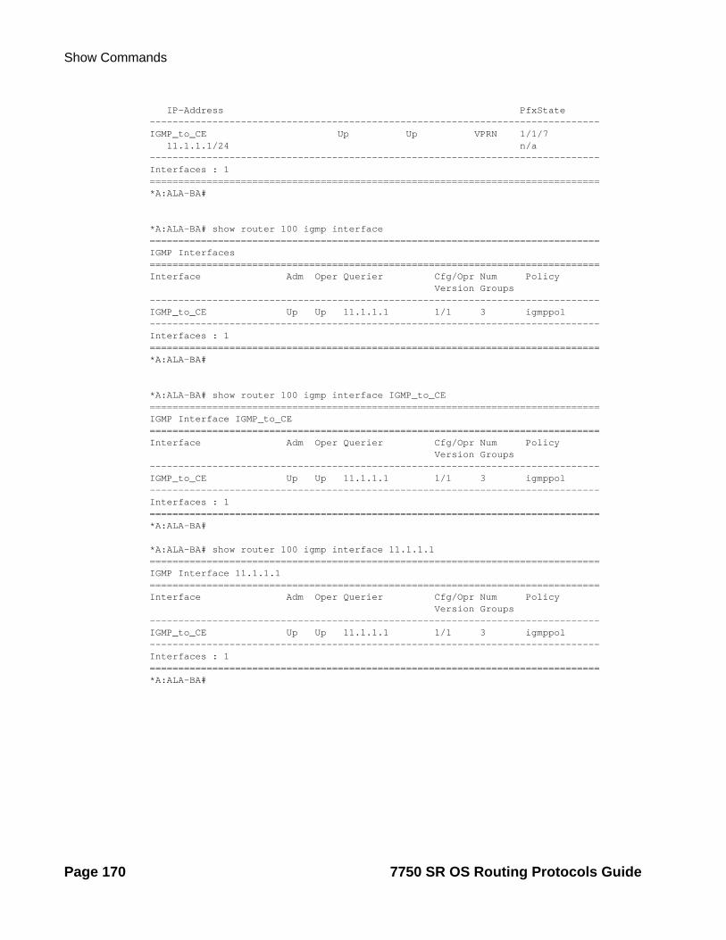
Show Commands
IP-Address PfxState -------------------------------------------------------------------------------IGMP_to_CE Up Up VPRN 1/1/7 11.1.1.1/24 n/a-------------------------------------------------------------------------------Interfaces : 1===============================================================================*A:ALA-BA#
*A:ALA-BA# show router 100 igmp interface ===============================================================================IGMP Interfaces===============================================================================Interface Adm Oper Querier Cfg/Opr Num Policy Version Groups -------------------------------------------------------------------------------IGMP_to_CE Up Up 11.1.1.1 1/1 3 igmppol -------------------------------------------------------------------------------Interfaces : 1===============================================================================*A:ALA-BA#
*A:ALA-BA# show router 100 igmp interface IGMP_to_CE ===============================================================================IGMP Interface IGMP_to_CE===============================================================================Interface Adm Oper Querier Cfg/Opr Num Policy Version Groups -------------------------------------------------------------------------------IGMP_to_CE Up Up 11.1.1.1 1/1 3 igmppol -------------------------------------------------------------------------------Interfaces : 1===============================================================================*A:ALA-BA#
*A:ALA-BA# show router 100 igmp interface 11.1.1.1 ===============================================================================IGMP Interface 11.1.1.1===============================================================================Interface Adm Oper Querier Cfg/Opr Num Policy Version Groups -------------------------------------------------------------------------------IGMP_to_CE Up Up 11.1.1.1 1/1 3 igmppol -------------------------------------------------------------------------------Interfaces : 1===============================================================================*A:ALA-BA#
Page 170 7750 SR OS Routing Protocols Guide

Multicast
*A:ALA-BA# show router 100 igmp interface IGMP_to_CE group 227.1.1.1 ===============================================================================IGMP Interface IGMP_to_CE===============================================================================Interface Adm Oper Querier Cfg/Opr Num Policy Version Groups -------------------------------------------------------------------------------IGMP_to_CE Up Up 11.1.1.1 1/1 3 igmppol -------------------------------------------------------------------------------IGMP Group-------------------------------------------------------------------------------Group Address : 227.1.1.1 Up Time : 0d 00:03:52 Interface : IGMP_to_CE Expires : never Last Reporter : 0.0.0.0 Mode : exclude V1 Host Timer : Not running Type : static V2 Host Timer : Not running Compat Mode : IGMP Version 3 -------------------------------------------------------------------------------Interfaces : 1===============================================================================*A:ALA-BA#
*A:ALA-BA# show router 100 igmp interface IGMP_to_CE group 227.1.1.1 detail ===============================================================================IGMP Interface IGMP_to_CE===============================================================================Interface : IGMP_to_CE Admin Status : Up Oper Status : Up Querier : 11.1.1.1 Querier Up Time : 0d 00:04:01 Querier Expiry Time: N/A Time for next query: 0d 00:13:42 Admin/Oper version : 1/1 Num Groups : 3 Policy : igmppol Subnet Check : Disabled Max Groups Allowed : 16000 Max Groups Till Now: 3 MCAC Policy Name : MCAC Const Adm St : Enable MCAC Max Unconst BW: no limit MCAC Max Mand BW : no limit MCAC In use Mand BW: 0 MCAC Avail Mand BW : unlimited MCAC In use Opnl BW: 0 MCAC Avail Opnl BW : unlimited -------------------------------------------------------------------------------IGMP Group-------------------------------------------------------------------------------Group Address : 227.1.1.1 Up Time : 0d 00:04:02 Interface : IGMP_to_CE Expires : never Last Reporter : 0.0.0.0 Mode : exclude V1 Host Timer : Not running Type : static V2 Host Timer : Not running Compat Mode : IGMP Version 3 -------------------------------------------------------------------------------Interfaces : 1===============================================================================*A:ALA-BA#
7750 SR OS Routing Protocols Guide Page 171

Show Commands
static
Syntax static [ip-int-name | ip-addr]
Context show>router>igmp
Description This command displays static IGMP, (*,G) and (S,G) information.
Parameters ip-int-name — Only displays the information associated with the specified IP interface name.
ip-addr — Only displays the information associated with the specified IP address.
Output Static IGMP Output — The following table provides static IGMP field descriptions.
Label Description
Source Displays entries which represents a source address from which receiv-ers are interested/not interested in receiving multicast traffic.
Group Displays the IP multicast group address for which this entry contains information.
Interface Displays the interface name.
Sample Output
*A:ALA-BA# show router 100 igmp static ==================================================================IGMP Static Group Source==================================================================Source Group Interface ------------------------------------------------------------------11.11.11.11 226.136.22.3 IGMP_to_CE * 227.1.1.1 IGMP_to_CE 22.22.22.22 239.255.255.255 IGMP_to_CE ------------------------------------------------------------------Static (*,G)/(S,G) Entries : 3==================================================================*A:ALA-BA#
statistics
Syntax statistics [ip-int-name | ip-address]statistics host [ip-address]
Context show>router>igmp
Description This command displays IGMP statistics information.
Parameters ip-int-name — Only displays the information associated with the specified IP interface name.
ip-address — Only displays the information associated with the specified IP address.
Page 172 7750 SR OS Routing Protocols Guide

Multicast
Output IGMP Statistics Output — The following table provides statistical IGMP field descriptions.
Label Description
IGMP Interface Statistics
The section listing the IGMP statistics for a particular interface.
Message Type Queries — The number of IGMP general queries transmitted or received on this interface.
Report — The total number of IGMP V1, V2, or V3 reports trans-mitted or received on this interface.
Leaves — The total number of IGMP leaves transmitted on this interface.
Received Displays the total number of IGMP packets received on this interface.
Transmitted Column that displays the total number of IGMP packets transmitted from this interface.
General Inter-face Statistics
The section listing the general IGMP statistics.
Bad Length Displays the total number of IGMP packets with bad length received on this interface.
Bad Checksum Displays the total number of IGMP packets with bad checksum received on this interface.
Unknown Type Displays the total number of IGMP packets with unknown type received on this interface.
Bad Receive If Displays the total number of IGMP packets incorrectly received on this interface.
Rx Non Local Displays the total number of IGMP packets received from a non-local sender.
Rx Wrong Version Displays the total number of IGMP packets with wrong versions received on this interface.
Policy Drops Displays the total number of times IGMP protocol instance matched the host IP address or group/source addresses specified in the import policy.
No Router Alert Displays the total number of IGMPv3 packets received on this inter-face which did not have the router alert flag set.
7750 SR OS Routing Protocols Guide Page 173

Show Commands
Sample Output
*A:ALA-BA# show router 100 igmp statistics =================================================IGMP Interface Statistics=================================================Message Type Received Transmitted -------------------------------------------------Queries 0 5 Report V1 0 0 Report V2 0 0 Report V3 0 0 Leaves 0 0 -------------------------------------------------General Interface Statistics-------------------------------------------------Bad Length : 0 Bad Checksum : 0 Unknown Type : 0 Bad Receive If : 0 Rx Non Local : 0 Rx Wrong Version : 0 Policy Drops : 0 No Router Alert : 0 Rx Bad Encodings : 0 Rx Pkt Drops : 0 -------------------------------------------------Source Group Statistics-------------------------------------------------(S,G) : 2 (*,G) : 1 =================================================*A:ALA-BA#
*B:Dut-C# show router igmp statistics host ==================================================IGMP Host Statistics==================================================Message Type Received Transmitted --------------------------------------------------Queries 0 1739 Report V1 0 0 Report V2 0 0 Report V3 10 0 Leaves 0 0 -------------------------------------------------------------------------------General Host Statistics-------------------------------------------------------------------------------Bad Length : 0Bad Checksum : 0Unknown Type : 0Bad Receive If : 0Rx Non Local : 0Rx Wrong Version : 0Policy Drops : 0No Router Alert : 0Rx Bad Encodings : 0 Local Scope Pkts : 0
Page 174 7750 SR OS Routing Protocols Guide

Multicast
Resvd Scope Pkts : 0MCAC Policy Drops : 0==================================================*B:Dut-C#
status
Syntax status
Context show>router>igmp
Description This command displays IGMP status information. If IGMP is not enabled, the following message appears:
A:NYC# show router igmp statusMINOR: CLI IGMP is not configured.A:NYC#
Output IGMP Status Output — The following table provides IGMP status field descriptions.
Label Description
Admin State Displays the administrative status of IGMP.
Oper State Displays the current operating state of this IGMP protocol instance on this router.
Query Interval The frequency at which IGMP query packets are transmitted.
Last Member Query Interval
The maximum response time inserted into group-specific queries sent in response to leave group messages, and is also the amount of time between group-specific query messages.
Query Response Interval
The maximum query response time advertised in IGMPv2 queries.
Robust Count Displays the number of times the router will retry a query.
Sample Output
*A:ALA-BA# show router 100 igmp status ===============================================================================IGMP Status===============================================================================Admin State : Up Oper State : Up Query Interval : 1024 Last Member Query Interval : 1024 Query Response Interval : 1023 Robust Count : 10 ===============================================================================*A:ALA-BA#
7750 SR OS Routing Protocols Guide Page 175

Show Router PIM Commands
Show Router PIM Commands
anycast
Syntax anycast [detail]
Context show>router>pim
Description This command displays PIM anycast rp-set information.
Parameters detail — Displays detailed information.
Output PIM anycast Output — The following table provides PIM anycast field descriptions
Label Description
Anycast Address Displays the candidate anycast address.
Anycast RP Peer Displays the candidate anycast RP peer address.
Sample Output
A:dut-d# show router pim anycast ===================================================PIM Anycast RP Entries===================================================Anycast RP Anycast RP Peer ---------------------------------------------------100.100.100.1 102.1.1.1 103.1.1.1 104.1.1.1 ---------------------------------------------------PIM Anycast RP Entries : 3===================================================
crp
Syntax crp [ip-address]
Context show>router>pim
Description Display PIM candidate RP (CRP) information received at the elected Bootstrap router (BSR).
Parameters ip-address — The candidate RP IP address.
Page 176 7750 SR OS Routing Protocols Guide

Multicast
Output PIM CRP Output — The following table provides PIM CRP field descriptions.
Label Description
RP Address Displays the Candidate RP address.
Group Address Displays the range of multicast group addresses for which the CRP is the Candidate RP.
Priority Displays the Candidate RP's priority for becoming a rendezvous point (RP). This value is used to elect RP for a group range. A value of 0 is considered as the highest priority.
Holdtime Displays the hold time of the candidate RP. It is used by the Bootstrap router to time out the RP entries if it does not listen to another CRP advertisement within the holdtime period.
Expiry The minimum time remaining before the CRP will be declared down. If the local router is not the BSR, this value is 0.
Candidate RPs Displays the number of CRP entries.
Sample Output
A:WAS# show router pim crp============================================================================PIM Candidate RPs============================================================================RP Address Group Address Priority Holdtime Expiry Time----------------------------------------------------------------------------2.22.187.236 224.0.0.0/4 192 150 0d 00:02:192.22.187.239 224.0.0.0/4 192 150 0d 00:02:192.22.187.240 224.0.0.0/4 192 150 0d 00:02:09----------------------------------------------------------------------------Candidate RPs : 3============================================================================A:WAS#
A:WAS# show router pim crp 2.22.187.236============================================================================PIM Candidate RPs============================================================================RP Address Group Address Priority Holdtime Expiry Time----------------------------------------------------------------------------2.22.187.236 224.0.0.0/4 192 150 0d 00:01:43----------------------------------------------------------------------------Candidate RPs : 1============================================================================A:WAS#
7750 SR OS Routing Protocols Guide Page 177

Show Router PIM Commands
s-pmsi
Syntax s-pmsi [mdSrcAddr [mdGrpAddr]] [detail]
Context show>router>pim
Description Displays the list of selective provider multicast service interfaces that are currently active.
Parameters mdSrcAddr — Specifies the source address of the multicast sender.
mdGrpAddr — Specifies the group address of the multicast sender.
detail — Displays detailed output.
Output PIM data MDT Output — The following table provides PIM data MDT descriptions.
Label Description
MD Grp Address Displays the IP multicast group address for which this entry contains information.
MD Src Address Displays the source address of the multicast sender. It will be 0 if the type is configured as starg. It will be the address of the Rendezvous Point (RP) if the type is configured as starRP.
MT Index Displays the index number.
Num VP SGs Displays the VPN number.
Sample Output
*B:node-6# show router 100 pim s-pmsi===============================================================================PIM Selective provider tunnels===============================================================================MD Src Address MD Grp Address MT Index Num VPN SGs -------------------------------------------------------------------------------200.200.200.7 230.0.89.72 24603 1 200.200.200.7 230.0.89.73 24604 1 200.200.200.7 230.0.89.74 24605 1 200.200.200.7 230.0.89.75 24606 1 200.200.200.7 230.0.89.76 24607 1 200.200.200.7 230.0.89.77 24608 1 200.200.200.7 230.0.89.78 24609 1 200.200.200.7 230.0.89.79 24610 1 200.200.200.7 230.0.89.80 24611 1 200.200.200.7 230.0.89.81 24612 1 200.200.200.7 230.0.89.82 24613 1 200.200.200.7 230.0.89.83 24614 1 200.200.200.7 230.0.89.84 24615 1 200.200.200.7 230.0.89.85 24616 1 200.200.200.7 230.0.89.86 24617 1 200.200.200.7 230.0.89.87 24618 1...===============================================================================*B:node-6#
Page 178 7750 SR OS Routing Protocols Guide

Multicast
*B:node-6# show router 100 pim s-pmsi detail===============================================================================PIM Selective provider tunnels===============================================================================Md Source Address : 200.200.200.7 Md Group Address : 230.0.89.72 Number of VPN SGs : 1 Uptime : 0d 00:00:18 MT IfIndex : 24603 Egress Fwding Rate : 163.2 kbps
VPN Group Address : 228.1.0.0 VPN Source Address : 11.2.102.1 State : RX Joined Expiry Timer : 0d 00:02:41 ===============================================================================PIM Selective provider tunnels===============================================================================Md Source Address : 200.200.200.7 Md Group Address : 230.0.89.73 Number of VPN SGs : 1 Uptime : 0d 00:00:18 MT IfIndex : 24604 Egress Fwding Rate : 163.2 kbps
VPN Group Address : 228.1.0.1 VPN Source Address : 11.2.102.1 State : RX Joined Expiry Timer : 0d 00:02:41 ===============================================================================PIM Selective provider tunnels===============================================================================Md Source Address : 200.200.200.7 Md Group Address : 230.0.89.74 Number of VPN SGs : 1 Uptime : 0d 00:00:20 MT IfIndex : 24605 Egress Fwding Rate : 165.7 kbps
VPN Group Address : 228.1.0.2 VPN Source Address : 11.2.102.1 State : RX Joined Expiry Timer : 0d 00:02:39 ===============================================================================PIM Selective provider tunnels===============================================================================Md Source Address : 200.200.200.7 Md Group Address : 230.0.89.75 Number of VPN SGs : 1 Uptime : 0d 00:00:20 MT IfIndex : 24606 Egress Fwding Rate : 165.7 kbps
VPN Group Address : 228.1.0.3 VPN Source Address : 11.2.102.1 State : RX Joined Expiry Timer : 0d 00:02:39 ===============================================================================*B:node-6#
group
Syntax group grp-ip-address [source ip-address [type {starstarrp | starg | sg}] [detail] [family]
Context show>router>pim
Description This command displays PIM source group database information.
Parameters grp-ip-address — Specifies the IP multicast group address for which this entry contains information.
source ip-address — Specifies the source address for which this entry contains information.
type starstarrp — Specifies that only (*, *, rp) entries be displayed.
7750 SR OS Routing Protocols Guide Page 179

Show Router PIM Commands
type starg — Specifies that only (*,G) entries be displayed.
type sg — specifies that only (S,G) entries be displayed.
detail — Displays detailed group information.
family — Displays either IPv4 or IPv6 information.
Output PIM Group Output — The following table provides PIM Group field descriptions.
Label Description
Group Address Displays the IP multicast group address for which this entry contains information.
Source Address Displays the source address of the multicast sender. It will be 0 if the type is configured as starg. It will be the address of the Rendezvous Point (RP) if the type is config-ured as starRP.
RP Address Displays the RP address.
Type Specifies the type of entry, (*,*, rp)/(*,G) or (S,G).
Spt Bit Specifies whether to forward on (*,*, rp)/(*,G) or on (S,G) state. It is updated when the (S,G) data comes on the RPF interface towards the source.
Incoming Intf Displays the interface on which the traffic comes in. It can be the RPF interface to the RP (if starg) or the source (if sg).
Num Oifs Displays the number of interfaces in the inherited outgoing interface list. An inherited list inherits the state from other types.
Flags Displays the different lists that this interface belongs to.
Keepalive Timer Exp
The keepalive timer is applicable only for (S,G) entries.The (S,G) keepalive timer is updated by data being forwarded using this (S,G) Forwarding state. It is used to keep (S,G) state alive in the absence of explicit (S,G) joins.
MRIB Next Hop Displays the next hop address towards the RP.
MRIB Src Flags Displays the MRIB information about the source. If the entry is of type starg or starstarrp, it will contain information about the RP for the group.
Up Time Displays the time since this source group entry was created.
Resolved By Displays the route table used for RPF check.
Up JP State Displays the upstream join prune state for this entry on the interface. PIM join prune messages are sent by the downstream routers towards the RPF neighbor.
Page 180 7750 SR OS Routing Protocols Guide

Multicast
Up JP Expiry Displays the minimum amount of time remaining before this entry will be aged out.
Up JP Rpt Displays the join prune Rpt state for this entry on the interface. PIM join/prune messages are sent by the downstream routers towards the RPF neighbor. (S,G, rpt) state is a result of receiving (S,G, rpt) JP mes-sage from the downstream router on the RP tree.
Up JP Rpt Over-ride
Displays the value used to delay triggered Join (S,G, rpt) messages to prevent implosions of triggered messages. If this has a non-zero value, it means that the router was in 'notPruned' state and it saw a prune (S,G, rpt) message being sent to RPF (S,G, rpt). If the router sees a join (S,G, rpt) override message being sent by some other router on the LAN while the timer is still non-zero, it simply can-cels the override timer. If it does not see a join (S,G, rpt) message, then on expiry of the override timer, it sends it's own join (S,G, rpt) message to RPF (S,G, rpt). A similar scenario exists when RPF (S,G, rpt) changes to become equal to RPF (*,G).
Register State Specifies the register state. The register state is kept at the source DR. When the host starts sending multicast packets and if there are no entries programmed for that group, the source DR sends a register packet to the RP (g). Register state transition happen based on the regis-ter stop timer and the response received from the RP.
Register Stop Exp
Displays the time remaining before the register state might transition to a different state.
Register from Anycast RP
Displays if the register packet for that group has been received from one of the RP from the anycast-RP set.
RPF Neighbor Displays the address of the RPF neighbor.
Outgoing Intf List
Displays a list of interfaces on which data is forwarded.
Curr Fwding Rate Displays the current forwarding rate of the multicast data for this group and source.
Forwarded Pack-ets
Displays the number of multicast packets that were forwarded to the interfaces in the outgoing interface list.
Discarded Pack-ets
Displays the number of multicast packets that matched this source group entry but were discarded. For (S,G) entries, if the traffic is getting forwarded on the SPT,the packets arriving from the RPT will be discarded.
Forwarded Octets Displays the number of octets forwarded.
RPF Mismatches Displays the number of multicast packets that matched this source group entry but they did not arrive on the interface.
Label Description (Continued)
7750 SR OS Routing Protocols Guide Page 181

Show Router PIM Commands
Sample Output
A:NYC>show>router>pim# group===============================================================================PIM Groups===============================================================================Group Address Source Address RP Address Type Spt Incoming Num Bit Intf Oifs-------------------------------------------------------------------------------224.24.24.24 * 2.22.187.240 <*,G> nyc-sjc 1239.255.255.250 * 2.22.187.240 <*,G> nyc-sjc 1-------------------------------------------------------------------------------Groups : 2===============================================================================A:NYC>show>router>pim#
A:NYC>show>router>pim# group 239.255.255.250===============================================================================PIM Groups===============================================================================Group Address Source Address RP Address Type Spt Incoming Num Bit Intf Oifs-------------------------------------------------------------------------------239.255.255.250 * 2.22.187.240 <*,G> nyc-sjc 1-------------------------------------------------------------------------------Groups : 1===============================================================================A:NYC>show>router>pim#
A:NYC>show>router>pim# group 239.255.255.250 detail===============================================================================PIM Source Group===============================================================================Group Address : 239.255.255.250 Source Address : 16.1.1.2 RP Address : 100.100.100.1 Type : (S,G) Flags : spt, rpt-prn-des Keepalive Timer Exp: 0d 00:03:07 MRIB Next Hop : 16.1.1.2 MRIB Src Flags : direct Up Time : 0d 00:00:50 Resolved By : rtable-u Up JP State : Joined Up JP Expiry : 0d 00:00:00 Up JP Rpt : Pruned Up JP Rpt Override : 0d 00:00:00 Register State : Pruned Register Stop Exp : 0d 00:00:47 Reg From Anycast RP: No RPF Neighbor : 16.1.1.2 Incoming Intf : SOURCE-3 Outgoing Intf List : To-Dut-A Curr Fwding Rate : 482.9 kbps
Spt threshold Displays the value of the SPT threshold configured for that group. 0 Kbps means that the switch to the SP tree will happen immediately.
Label Description (Continued)
Page 182 7750 SR OS Routing Protocols Guide
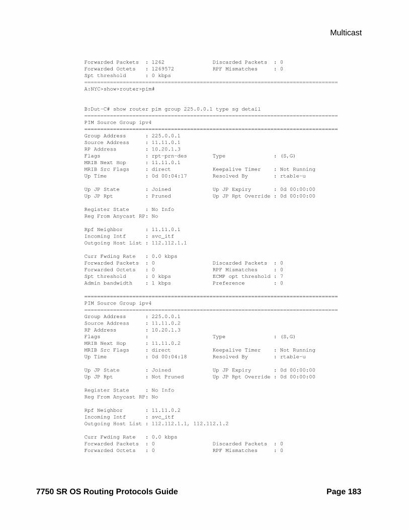
Multicast
Forwarded Packets : 1262 Discarded Packets : 0 Forwarded Octets : 1269572 RPF Mismatches : 0 Spt threshold : 0 kbps ===============================================================================A:NYC>show>router>pim#
B:Dut-C# show router pim group 225.0.0.1 type sg detail ===============================================================================PIM Source Group ipv4===============================================================================Group Address : 225.0.0.1Source Address : 11.11.0.1RP Address : 10.20.1.3Flags : rpt-prn-des Type : (S,G)MRIB Next Hop : 11.11.0.1MRIB Src Flags : direct Keepalive Timer : Not RunningUp Time : 0d 00:04:17 Resolved By : rtable-u Up JP State : Joined Up JP Expiry : 0d 00:00:00Up JP Rpt : Pruned Up JP Rpt Override : 0d 00:00:00 Register State : No Info Reg From Anycast RP: No Rpf Neighbor : 11.11.0.1Incoming Intf : svc_itfOutgoing Host List : 112.112.1.1 Curr Fwding Rate : 0.0 kbps Forwarded Packets : 0 Discarded Packets : 0Forwarded Octets : 0 RPF Mismatches : 0Spt threshold : 0 kbps ECMP opt threshold : 7Admin bandwidth : 1 kbps Preference : 0
===============================================================================PIM Source Group ipv4===============================================================================Group Address : 225.0.0.1Source Address : 11.11.0.2RP Address : 10.20.1.3Flags : Type : (S,G)MRIB Next Hop : 11.11.0.2MRIB Src Flags : direct Keepalive Timer : Not RunningUp Time : 0d 00:04:18 Resolved By : rtable-u Up JP State : Joined Up JP Expiry : 0d 00:00:00Up JP Rpt : Not Pruned Up JP Rpt Override : 0d 00:00:00 Register State : No Info Reg From Anycast RP: No Rpf Neighbor : 11.11.0.2 Incoming Intf : svc_itfOutgoing Host List : 112.112.1.1, 112.112.1.2 Curr Fwding Rate : 0.0 kbps Forwarded Packets : 0 Discarded Packets : 0Forwarded Octets : 0 RPF Mismatches : 0
7750 SR OS Routing Protocols Guide Page 183

Show Router PIM Commands
Spt threshold : 0 kbps ECMP opt threshold : 7Admin bandwidth : 1 kbps Preference : 0-------------------------------------------------------------------------------Groups : 2===============================================================================*B:Dut-C#
interface
Syntax interface [ip-int-name | mt-int-name |ip-address] [group grp-ip-address | source ip-address [type {starstarrp | starg | sg}] [detail] [family]
Context show>router>pim
Description This command displays PIM interface information and the (S,G)/(*,G)/(*, *, rp) state of the interface.
Parameters ip-int-name — Only displays the interface information associated with the specified IP interface name.
ip-address — Only displays the interface information associated with the specified IP address.
group grp-ip-address — Specifies the IP multicast group address for which this entry contains information.
source ip-address — Specifies the source address for which this entry contains information.
If the type is starg, the value of this object will be zero.
If the type is starstarrp, the value of this object will be address of the RP.
type — Specifies the type of this entry.
Values starstarrp, starg, sg
detail — Displays detailed interface information.
family — Displays IPv4 or IPv6 information for the interface.
Output PIM Interface Output — The following table provides PIM interface field descriptions.
Label Description
Admin State Displays the administrative state for PIM protocol on this interface.
Oper State Displays the current operational state of PIM protocol on this interface.
DR Displays the designated router on this PIM interface.
DR Priority Displays the priority value sent in PIM Hello messages and that is used by routers to elect the designated router (DR).
Hello Intvl Indicates the frequency at which PIM Hello messages are transmitted on this interface.
Page 184 7750 SR OS Routing Protocols Guide

Multicast
Sample Output
ALA-1# show router pim interface===============================================================================PIM Interfaces===============================================================================Interface Admin Oper DR DR Hello State State Priority Intvl-------------------------------------------------------------------------------system Up Up N/A 1 30ip-10.1.7.1 Up Up 10.1.7.7 5 30ip-10.1.2.1 Up Up 10.1.2.2 5 30ip-100.111.1.1 Up Up 100.111.1.1 5 30-------------------------------------------------------------------------------Interfaces : 4===============================================================================ALA-1#
ALA-1# show router pim interface ip-10.1.2.1 detail===============================================================================PIM Interface ip-10.1.2.1===============================================================================Interface Admin Oper DR DR Hello State State Priority Intvl-------------------------------------------------------------------------------ip-10.1.2.1 Up Up 10.1.2.2 5 30-------------------------------------------------------------------------------PIM Group Source-------------------------------------------------------------------------------Group Address : 228.101.0.5 Src Address : 100.111.1.2Interface : ip-10.1.2.1 Type : <S,G>RP Address : 200.200.200.4
Join Prune State : Join Expires : 0d 00:03:00Prune Pend Expires : N/A
Assert State : No Info-------------------------------------------------------------------------------Interfaces : 1===============================================================================ALA-1#
ALA-1# show router pim interface group===============================================================================PIM Interface ip-10.1.7.1===============================================================================Interface Admin Oper DR DR Hello State State Priority Intvl-------------------------------------------------------------------------------ip-10.1.7.1 Up Up 10.1.7.7 5 30-------------------------------------------------------------------------------Group Address Source Address RP Address Type JP Assert-------------------------------------------------------------------------------228.101.0.0 100.111.1.2 200.200.200.4 <S,G> Join No Info228.101.0.1 100.111.1.2 200.200.200.4 <S,G> Join No Info228.101.0.2 100.111.1.2 200.200.200.4 <S,G> Join No Info228.101.0.3 100.111.1.2 200.200.200.4 <S,G> Join No Info
7750 SR OS Routing Protocols Guide Page 185

Show Router PIM Commands
228.101.0.4 100.111.1.2 200.200.200.4 <S,G> Join No Info228.101.0.6 100.111.1.2 200.200.200.4 <S,G> Join No Info228.101.0.7 100.111.1.2 200.200.200.4 <S,G> Join No Info228.101.0.8 100.111.1.2 200.200.200.4 <S,G> Join No Info228.101.0.9 100.111.1.2 200.200.200.4 <S,G> Join No Info===============================================================================PIM Interface ip-10.1.2.1===============================================================================Interface Admin Oper DR DR Hello State State Priority Intvl-------------------------------------------------------------------------------ip-10.1.2.1 Up Up 10.1.2.2 5 30-------------------------------------------------------------------------------Group Address Source Address RP Address Type JP Assert-------------------------------------------------------------------------------228.101.0.5 100.111.1.2 200.200.200.4 <S,G> Join No Info===============================================================================PIM Interface ip-100.111.1.1===============================================================================Interface Admin Oper DR DR Hello State State Priority Intvl-------------------------------------------------------------------------------ip-100.111.1.1 Up Up 100.111.1.1 5 30-------------------------------------------------------------------------------Group Address Source Address RP Address Type JP Assert-------------------------------------------------------------------------------228.102.0.0 * 200.200.200.4 <*,G> Join No Info228.102.0.1 * 200.200.200.4 <*,G> Join No Info228.102.0.2 * 200.200.200.4 <*,G> Join No Info228.102.0.3 * 200.200.200.4 <*,G> Join No Info228.102.0.4 * 200.200.200.4 <*,G> Join No Info228.102.0.5 * 200.200.200.4 <*,G> Join No Info228.102.0.6 * 200.200.200.4 <*,G> Join No Info228.102.0.7 * 200.200.200.4 <*,G> Join No Info228.102.0.8 * 200.200.200.4 <*,G> Join No Info228.102.0.9 * 200.200.200.4 <*,G> Join No Info-------------------------------------------------------------------------------Interfaces : 3===============================================================================ALA-1#
ALA-1# show router pim interface group 228.102.0.0 detail===============================================================================PIM Interface ip-100.111.1.1===============================================================================Interface Admin Oper DR DR Hello State State Priority Intvl-------------------------------------------------------------------------------ip-100.111.1.1 Up Up 100.111.1.1 5 30-------------------------------------------------------------------------------PIM Group Source-------------------------------------------------------------------------------Group Address : 228.102.0.0 Src Address : *Interface : ip-100.111.1.1 Type : <*,G>RP Address : 200.200.200.4
Join Prune State : Join Expires : 0d 00:02:05Prune Pend Expires : N/A
Page 186 7750 SR OS Routing Protocols Guide

Multicast
Assert State : No Info-------------------------------------------------------------------------------Interfaces : 1===============================================================================ALA-1#
ALA-1# show router pim interface type starg===============================================================================PIM Interface ip-100.111.1.1===============================================================================Interface Admin Oper DR DR Hello State State Priority Intvl-------------------------------------------------------------------------------ip-100.111.1.1 Up Up 100.111.1.1 5 30-------------------------------------------------------------------------------Group Address Source Address RP Address Type JP Assert-------------------------------------------------------------------------------228.102.0.0 * 200.200.200.4 <*,G> Join No Info228.102.0.1 * 200.200.200.4 <*,G> Join No Info228.102.0.2 * 200.200.200.4 <*,G> Join No Info228.102.0.3 * 200.200.200.4 <*,G> Join No Info228.102.0.4 * 200.200.200.4 <*,G> Join No Info228.102.0.5 * 200.200.200.4 <*,G> Join No Info228.102.0.6 * 200.200.200.4 <*,G> Join No Info228.102.0.7 * 200.200.200.4 <*,G> Join No Info228.102.0.8 * 200.200.200.4 <*,G> Join No Info228.102.0.9 * 200.200.200.4 <*,G> Join No Info-------------------------------------------------------------------------------Interfaces : 1===============================================================================ALA-1#
A:SetupCLI# show router pim interface detail===============================================================================PIM Interface int1===============================================================================Interface : int1Admin Status : Up Oper Status : UpDR : 10.1.1.1 Oper DR Priority : 1BSM RA Check : Disabled Cfg DR Priority : 1Hello Interval : 30 Time for next hello: 0d 00:00:23Multicast Senders : auto Hello Multiplier : 35J/P Tracking Admin : Disabled J/P Tracking Oper : DisabledAuto-created : No Improved Assert : EnabledSticky-DR : Disabled Sticky-DR Priority : N/AMax Groups Allowed : 0 Max Groups Till Now: 0Num Groups : 0 Bfd Enabled : No===============================================================================PIM Interface sender===============================================================================Interface : senderAdmin Status : Up Oper Status : UpDR : 11.1.1.1 Oper DR Priority : 1===============================================================================A:SetupCLI#
7750 SR OS Routing Protocols Guide Page 187

Show Router PIM Commands
neighbor
Syntax neighbor [ip-address | ip-int-name [address ip-address]] [detail] [family]
Context show>router>pim
Description This command displays PIM neighbor information.
This can be important if an interface has more than one adjacency. For example, a LAN-interface configuration with three routers connected and all are running PIM on their LAN interfaces. These routers then have two adjacencies on their LAN interface, each with different neighbors. If the address address parameter is not defined in this example, then the show command output would display two adjacencies.
Parameters neighbor ip-int-name — Only displays the interface information associated with the specified IP interface name.
neighbor ip-address — Only displays the interface information associated with the specified IP address.
address ip-address — The ip-address of the neighbor, on the other side of the interface.
detail — Displays detailed neighbor information.
family — Displays either IPv4 or IPv6 information for the specified neighbor.
Output PIM Neighbor Output — The following table provides PIM neighbor field descriptions.
Label Description
Interface Displays the neighbor’s interface name.
Nbr DR Priority Displays the value of the neighbor's DR priority which is received in the hello message.
Nbr Address Displays the neighbor’s address.
Up Time Displays the time since this PIM neighbor (last) became a neighborof the local router.
Expiry Time Displays the minimum time remaining before this PIM neighbor will be aged out. 0 — Means that this neighbor will never be aged out. This happens when the PIM neighbor sends a Hello message with holdtime set to `0xffff'.
Hold Time Displays the value of the hold time present in the hello message.
DR Priority Displays the value of the neighbor's DR priority which is received in the hello message.
Tracking Support Displays whether the T bit in the LAN prune delay option was present in the hello message. This indicates the neighbor's capability to disable join message suppression.
LAN Delay Displays the value of the LAN delay field present in the hello message received from the neighbor.
Page 188 7750 SR OS Routing Protocols Guide

Multicast
Sample Output
ALA-1# show router pim neighbor===============================================================================PIM Neighbors===============================================================================Interface Nbr DR Nbr Address Up Time Expiry Time Hold Priority Time-------------------------------------------------------------------------------ip-10.1.7.1 5 10.1.7.7 0d 00:10:39 0d 00:01:36 105ip-10.1.2.1 5 10.1.2.2 0d 00:10:39 0d 00:01:35 105ip-100.111.1.1 3 100.111.1.2 0d 00:09:31 0d 00:01:15 105-------------------------------------------------------------------------------Neighbors : 3===============================================================================ALA-1#
ALA-1# show router pim neighbor detail===============================================================================PIM Neighbor===============================================================================Interface : ip-10.1.7.1Neighbor Addr : 10.1.7.7 DR Priority : 5Tracking Support : No LAN Delay(ms) : 500Gen Id : 26470 Override Intvl(ms) : 2500Up Time : 0d 00:10:41 Expiry Time : 0d 00:01:34Hold Time(sec) : 105
===============================================================================PIM Neighbor===============================================================================Interface : ip-10.1.2.1Neighbor Addr : 10.1.2.2 DR Priority : 5Tracking Support : No LAN Delay(ms) : 500Gen Id : 37928 Override Intvl(ms) : 2500Up Time : 0d 00:10:42 Expiry Time : 0d 00:01:33Hold Time(sec) : 105
===============================================================================PIM Neighbor===============================================================================
Gen Id Displays a randomly generated 32-bit value that is regenerated each time PIM forwarding is started or restarted on the interface, including when the router itself restarts. When a hello message with a new GenID is received from a neighbor, any old hello information about that neighbor is discarded and superseded by the information from the new hello message.
Override Intvl (ms)
Displays the value of the override interval present in the Hello mes-sage.
Label Description (Continued)
7750 SR OS Routing Protocols Guide Page 189

Show Router PIM Commands
Interface : ip-100.111.1.1Neighbor Addr : 100.111.1.2 DR Priority : 3Tracking Support : No LAN Delay(ms) : 500Gen Id : 742098371 Override Intvl(ms) : 2500Up Time : 0d 00:09:33 Expiry Time : 0d 00:01:43Hold Time(sec) : 105-------------------------------------------------------------------------------Neighbors : 3===============================================================================ALA-1#
rp
Syntax rp ip-address
Context show>router>pim
Description This command displays the rendezvous point (RP) set information built by the router.
Parameters ip-address — Specifies the IP address of the RP.
Output PIM Neighbor Output — The following table provides PIM neighbor field descriptions.
Label Description
Group Address Displays the multicast group address of the entry.
RP Address Displays the address of the Rendezvous Point (RP).
Type Specifies whether the entry was learned through the Bootstrap mecha-nism or if it was statically configured.
Priority Displays the priority for the specified group address. The higher the value, the higher the priority.
Holdtime Displays the value of the hold time present in the BSM message.
Sample Output
A:ALA-1# show router pim rp==================================================================PIM RP Set==================================================================Group Address RP Address Type Priority Holdtime------------------------------------------------------------------224.0.0.0/4 200.200.200.4 Dynamic 192 150 10.1.7.1 Static 1 N/A------------------------------------------------------------------Group Prefixes : 1==================================================================A:ALA-1#
A:ALA-1# show router pim rp 10.1.7.1
Page 190 7750 SR OS Routing Protocols Guide

Multicast
==================================================================PIM RP Set==================================================================Group Address RP Address Type Priority Holdtime------------------------------------------------------------------224.0.0.0/4 10.1.7.1 Static 1 N/A------------------------------------------------------------------Group Prefixes : 1==================================================================A:ALA-1#
rp-hash
Syntax rp-hash grp-ip-address
Context show>router>pim
Description This command hashes the RP for the specified group from the RP set.
Parameters grp-ip-address — Displays specific multicast group addresses.
Output PIM RP-Hash Output — The following table provides RP-Hash output field descriptions.
Label Description
Group Address Displays the multicast group address of the entry.
RP Address Displays the address of the Rendezvous Point (RP).
Type Specifies whether the entry was learned through the Bootstrap mecha-nism or if it was statically configured.
Sample Output
A:ALA-1# show router pim rp-hash 228.101.0.0==============================================PIM Group-To-RP mapping==============================================Group Address RP Address Type----------------------------------------------228.101.0.0 200.200.200.4 Bootstrap==============================================A:ALA-1#
A:ALA-1# show router pim rp-hash 228.101.0.6==============================================PIM Group-To-RP mapping==============================================Group Address RP Address Type----------------------------------------------228.101.0.6 200.200.200.4 Bootstrap==============================================A:ALA-1#
7750 SR OS Routing Protocols Guide Page 191

Show Router PIM Commands
statistics
Syntax statistics [ip-int-name | mt-int-name | ip-address] [family]
Context show>router>pim
Description This command displays statistics for a particular PIM instance.
Parameters ip-int-name — Only displays the interface information associated with the specified IP interface name.
ip-address — Only displays the interface information associated with the specified IP address.
family — Displays either IPv4 or IPv6 information.
Output PIM Statistics Output — The following table provides PIM statistics output field descriptions.
Label Description
PIM Statistics The section listing the PIM statistics for a particular interface.
Message Type Displays the type of message.
Hello — Displays the number of PIM hello messages received or transmitted on this interface.
Join Prune — Displays the number of PIM join prune messages received or transmitted on this interface.
Asserts — Displays the number of PIM assert messages received or transmitted on this interface.
Register — Displays the number of register messages received or transmitted on this interface.
Null Register — Displays the number of PIM null register mes-sages received or transmitted on this interface.
Register Stop — Displays the number of PIM register stop mes-sages received or transmitted on this interface.
BSM — Displays the number of PIM Bootstrap messages (BSM) received or transmitted on this interface.
Candidate RP Adv — Displays the number of candidate RP advertisements.
Total Packets — Displays the total number of packets transmit-ted and received on this interface.
Received Displays the number of messages received on this interface.
Transmitted Displays the number of multicast data packets transmitted on this inter-face.
Rx Errors Displays the total number of receive errors.
Page 192 7750 SR OS Routing Protocols Guide

Multicast
General Inter-face Statistics
The section listing the general PIM interface statistics.
Register TTL Drop
Displays the number of multicast data packets which could not be encapsulated in Register messages because the time to live (TTL) was zero.
Tx Register MTU Drop
Displays the number of Bootstrap messages received on this interface but were dropped.
Rx Invalid Reg-ister
Displays the number of invalid PIM register messages received on this interface.
Rx Neighbor Unknown
Displays the number of PIM messages (other than hello messages) which were received on this interface and were rejected because the adjacency with the neighbor router was not already established.
Rx Bad Checksum Discard
Displays the number of PIM messages received on this interface which were discarded because of bad checksum.
Rx Bad Encoding Displays the number of PIM messages with bad encodings received on this interface.
Rx Bad Version Discard
Displays the number of PIM messages with bad versions received on this interface.
Rx CRP No Router Alert
Displays the number of candidate-rp advertisements (C-RP-Adv) received on this interface which had no router alert option set.
Rx Invalid Join Prune
Displays the number of invalid PIM join prune messages received on this interface.
Rx Unknown PDU Type
Displays the number of packets received with an unsupported PIM type.
Join Policy Drops
Displays the number of times the join policy match resulted in drop-ping PIM join-prune message or one of the source group contained in the message.
Register Policy Drops
Displays the number of times the register policy match resulted in dropping PIM register message.
Bootstrap Import Policy Drops
Displays the number of Bootstrap messages received on this interface but were dropped because of Bootstrap import policy.
Bootstrap Export Policy Drops
Displays the number of Bootstrap messages that were not transmitted on this interface because of Bootstrap export policy.
Source Group Statistics
The section listing the source group statistics.
(S,G) Displays the number of entries in which the type is (S,G).
Label Description (Continued)
7750 SR OS Routing Protocols Guide Page 193

Show Router PIM Commands
Sample output
A:ALA-1# show router pim statistics================================================================PIM Statistics================================================================Message Type Received Transmitted Rx Errors----------------------------------------------------------------Hello 198 200 0Join Prune 96 75 0Asserts 0 0 0Register 0 30 0Null Register 0 160 0Register Stop 180 0 0BSM 34 76 0Candidate RP Adv 0 0 0Total Packets 546 541----------------------------------------------------------------General Interface Statistics----------------------------------------------------------------Register TTL Drop : 0Tx Register MTU Drop : 0Rx Invalid Register : 0Rx Neighbor Unknown : 0Rx Bad Checksum Discard : 0Rx Bad Encoding : 0Rx Bad Version Discard : 0Rx CRP No Router Alert : 0Rx Invalid Join Prune : 120Rx Unknown PDU Type : 0Join Policy Drops : 0Register Policy Drops : 0Bootstrap Import Policy Drops : 0Bootstrap Export Policy Drops : 0----------------------------------------------------------------Source Group Statistics----------------------------------------------------------------(S,G) : 10(*,G) : 10(*,*,RP) : 0================================================================A:ALA-1#
A:ALA-1# show router pim statistics 10.1.7.1================================================================PIM Interface 10.1.7.1 Statistics================================================================Message Type Received Transmitted Rx Errors----------------------------------------------------------------Hello 62 66 0Join Prune 36 21 0
(*,G) Displays the number of entries in which the type is (*,G).
(*,*,RP) Displays the number of entries in which the type is (*, *, rp).
Label Description (Continued)
Page 194 7750 SR OS Routing Protocols Guide

Multicast
Asserts 0 0 0Register 0 0 0Null Register 0 0 0Register Stop 0 0 0BSM 33 3 0Total Packets 134 90----------------------------------------------------------------General Interface Statistics----------------------------------------------------------------Register TTL Drop : 0Tx Register MTU Drop : 0Rx Invalid Register : 0Rx Neighbor Unknown : 0Rx Bad Checksum Discard : 0Rx Bad Encoding : 0Rx Bad Version Discard : 0Rx CRP No Router Alert : 0Rx Invalid Join Prune : 0Rx Unknown PDU Type : 0Join Policy Drops : 0Register Policy Drops : 0Bootstrap Import Policy Drops : 0Bootstrap Export Policy Drops : 0----------------------------------------------------------------Interface Source Group Statistics----------------------------------------------------------------(S,G) : 9(*,G) : 0(*,*,RP) : 0================================================================A:ALA-1#
A:ALA-1# show router pim statistics ip-10.1.7.1================================================================PIM Interface ip-10.1.7.1 Statistics================================================================Message Type Received Transmitted Rx Errors----------------------------------------------------------------Hello 63 67 0Join Prune 36 21 0Asserts 0 0 0Register 0 0 0Null Register 0 0 0Register Stop 0 0 0BSM 33 3 0Total Packets 135 91----------------------------------------------------------------General Interface Statistics----------------------------------------------------------------Register TTL Drop : 0Tx Register MTU Drop : 0Rx Invalid Register : 0Rx Neighbor Unknown : 0Rx Bad Checksum Discard : 0Rx Bad Encoding : 0Rx Bad Version Discard : 0Rx CRP No Router Alert : 0Rx Invalid Join Prune : 0Rx Unknown PDU Type : 0
7750 SR OS Routing Protocols Guide Page 195

Show Router PIM Commands
Join Policy Drops : 0Register Policy Drops : 0Bootstrap Import Policy Drops : 0Bootstrap Export Policy Drops : 0----------------------------------------------------------------Interface Source Group Statistics----------------------------------------------------------------(S,G) : 9(*,G) : 0(*,*,RP) : 0================================================================A:ALA-1#
status
Syntax status [detail] [family]
Context show>router>pim
Description This command displays PIM status. The Oper Status reflects the combined operational status of IPv4/IPv6 PIM protocol status. If both are down, then Oper Status will be reflected as down. If IPv4 or IPv6 reflects up, the Oper Status will reflect up.
If PIM is not enabled, the following message appears:
A:NYC# show router pim statusMINOR: CLI PIM is not configured.A:NYC#
Parameters detail — Displays detailed statis information.
family — Displays either IPv4 or IPv6 information.
Output PIM Status Output — The following table provides PIM status output field descriptions.
Label Description
Admin State Displays the administrative status of PIM.
Oper State Displays the current operating state of this PIM protocol instance.
BSR State Displays the state of the router with respect to the Bootstrap mecha-nism.
Address Displays the address of the elected Bootstrap router.
Expiry Time Displays the time remaining before the router sends the next Bootstrap message.
Priority Displays the priority of the elected Bootstrap router. The higher the value, the higher the priority.
Hash Mask Length Displays the hash mask length of the Bootstrap router.
Up Time Displays the time since the current E-BSR became the Bootstrap router.
Page 196 7750 SR OS Routing Protocols Guide

Multicast
Sample Output
A:dut-d# show router pim status ===============================================================================PIM Status===============================================================================Admin State : Up Oper State : Up
BSR State : Accept Any
Elected BSR Address : None Expiry Time : N/A Priority : N/A Hash Mask Length : N/A Up Time : N/A
RPF Intf towards Displays the RPF interface towards the elected BSR. The value is zero if there is no elected BSR in the network.
Address Displays the address of the candidate BSR router.
Expiry Time Displays the time remaining before the router sends the next Bootstrap message.
Priority Displays the priority of the Bootstrap router. The higher the value, the higher the priority.
Hash Mask Length Displays the hash mask length of the candidate Bootstrap router.
Up Time Displays the time since becoming the Bootstrap router.
Admin State Displays the administrative status of CRP.
Oper State Displays the current operating state of the C-RP mechanism.
Address Displays the local RP address.
Priority Displays the CRP's priority for becoming a rendezvous point (RP). A 0 value is the highest priority.
Holdtime Displays the hold time of the candidate RP. It is used by the Bootstrap router to timeout the RP entries if it does not listen to another CRP advertisement within the holdtime period.
Policy Displays the PIM policies for a particular PIM instance.
Default Group Displays the default core group address.
RPF Table Displays the route table used for RPF check.
MC-ECMP-Hashing Displays if hash-based multicast balancing of traffic over ECMP links is enabled or disabled.
Label Description (Continued)
7750 SR OS Routing Protocols Guide Page 197

Show Router PIM Commands
RPF Intf towards E-BSR : N/A
Candidate BSR Admin State : Down Oper State : Down Address : None Priority : 0 Hash Mask Length : 30
Candidate RP Admin State : Down Oper State : Down Address : None Priority : 192 Holdtime : 150
MC-ECMP-Hashing : Enabled
Policy : None
Default Group : 239.1.1.1
RPF Table : rtable-m ===============================================================================A:dut-d#
mld
Syntax mld
Context show>router
Description This command displays MLD related information.
group
Syntax group [grp-ipv6-address]
Context show>router>mld
Description This command displays MLD group information.
Parameters grp-ipv6-address — Specifies the IPv6 group address.
Values ipv6-address x:x:x:x:x:x:x:x (eight 16-bit pieces)x:x:x:x:x:x:d.d.d.d x: [0..FFFF]H d: [0..255]D
Output *A:SR7# show router mld group ===============================================================================MLD Groups===============================================================================
Page 198 7750 SR OS Routing Protocols Guide

Multicast
No Matching Entries===============================================================================*A:SR7#
*A:SR7# show router mld interface ===============================================================================MLD Interfaces===============================================================================Interface Adm Oper Cfg/Opr Num Policy Querier Version Groups -------------------------------------------------------------------------------Host4_Srce1_IPv6 Up Up 2/2 0 none FE80::216:4DFF:FED4:4D5BHost1 Up Up 2/2 0 none FE80::216:4DFF:FED4:4D5BHost2 Up Up 2/2 0 none FE80::216:4DFF:FE51:3728Host3_vlan1 Up Up 2/2 0 none FE80::216:4DFF:FE51:3729Host3_vlan2 Up Up 2/2 0 none FE80::216:4DFF:FE51:3729Host3_vlan3 Up Up 2/2 0 none FE80::216:4DFF:FE51:3729Host3_vlan4 Up Up 2/2 0 none FE80::216:4DFF:FE51:3729Host3_vlan5 Up Up 2/2 0 none *A:SR7# show router mld ssm-translate ===============================================================================MLD SSM Tranlate Entries===============================================================================No Matching Entries===============================================================================*A:SR7#
*A:SR7# show router mld group ===============================================================================MLD Groups===============================================================================(3FFE:100::2:100,FF05::1:1) Up Time : 0d 00:00:31 Fwd List : Host1 (3FFE:100::2:100,FF05::1:2) Up Time : 0d 00:00:31 Fwd List : Host1 (3FFE:100::2:100,FF05::1:3) Up Time : 0d 00:00:31 Fwd List : Host1 (3FFE:100::2:100,FF05::1:4) Up Time : 0d 00:00:31 Fwd List : Host1 (3FFE:100::2:100,FF05::1:5)===============================================================================*A:SR7#
7750 SR OS Routing Protocols Guide Page 199

Show Router PIM Commands
*A:SR7# show router mld group ff05::1:1 ===============================================================================MLD Groups===============================================================================(3FFE:100::2:100,FF05::1:1) Up Time : 0d 00:00:40 Fwd List : Host1 -------------------------------------------------------------------------------(*,G)/(S,G) Entries : 1===============================================================================*A:SR7#
*A:SR7# show router mld group ff05::1 ===============================================================================MLD Groups===============================================================================No Matching Entries===============================================================================
interface
Syntax interface [ip-int-name | ip-address] [group] [grp-ipv6-address] [detail]
Context show>router>mld
Description This command displays MLD interface information.
Parameters ip-int-name|ip-address — Specifies the IP interface name or interface address.
group grp-ipv6-address — Specifies the IPv6 group address.
Values ipv6-address x:x:x:x:x:x:x:x (eight 16-bit pieces)x:x:x:x:x:x:d.d.d.d x: [0..FFFF]H d: [0..255]D
detail — Displays detailed information.
Output *A:SR7# show router mld interface Host1 detail ===============================================================================MLD Interface Host1===============================================================================Interface : Host1 Admin Status : Up Oper Status : Up Querier : FE80::216:4DFF:FED4:4D5BQuerier Up Time : 0d 00:02:18 Querier Expiry Time : N/A Time for next query: 0d 00:15:25 Admin/Oper version : 2/2 Num Groups : 6000 Policy : none Max Groups Allowed : No Limit Max Groups Till Now: 6000 Query Interval : 0 Query Resp Interval: 0 Last List Qry Interval : 0 -------------------------------------------------------------------------------MLD Group
Page 200 7750 SR OS Routing Protocols Guide

Multicast
-------------------------------------------------------------------------------Group Address : FF05::1:1Last Reporter : FE80::1Interface : Host1 Expires : N/A Up Time : 0d 00:00:10 Mode : include V1 Host Timer : Not running Type : dynamic Compat Mode : MLD Version 2 -------------------------------------------------------------------------------Source Expires Type Fwd/Blk-------------------------------------------------------------------------------3FFE:100::2:100 0d 00:34:07 dynamic Fwd-------------------------------------------------------------------------------MLD Group-------------------------------------------------------------------------------Group Address : FF05::1:2Last Reporter : FE80::1Interface : Host1 Expires : N/A Up Time : 0d 00:00:11 Mode : include V1 Host Timer : Not running Type : dynamic Compat Mode : MLD Version 2 -------------------------------------------------------------------------------Source Expires Type Fwd/Blk-------------------------------------------------------------------------------3FFE:100::2:100 0d 00:34:07 dynamic Fwd-------------------------------------------------------------------------------MLD Group -------------------------------------------------------------------------------Group Address : FF05::1:3Last Reporter : FE80::1Interface : Host1 Expires : N/A Up Time : 0d 00:00:11 Mode : include V1 Host Timer : Not running Type : dynamic Compat Mode : MLD Version 2 -------------------------------------------------------------------------------Source Expires Type Fwd/Blk-------------------------------------------------------------------------------3FFE:100::2:100 0d 00:34:07 dynamic Fwd-------------------------------------------------------------------------------MLD Group-------------------------------------------------------------------------------Group Address : FF05::1:4Last Reporter : FE80::1Interface : Host1 Expires : N/A Up Time : 0d 00:00:12 Mode : include V1 Host Timer : Not running Type : dynamic Compat Mode : MLD Version 2 -------------------------------------------------------------------------------Source Expires Type Fwd/Blk-------------------------------------------------------------------------------3FFE:100::2:100 0d 00:34:06 dynamic Fwd-------------------------------------------------------------------------------
7750 SR OS Routing Protocols Guide Page 201

Show Router PIM Commands
MLD Group-------------------------------------------------------------------------------Group Address : FF05::1:5Last Reporter : FE80::1Interface : Host1 Expires : N/A Up Time : 0d 00:00:12 Mode : include V1 Host Timer : Not running Type : dynamic Compat Mode : MLD Version 2 -------------------------------------------------------------------------------Source Expires Type Fwd/Blk-------------------------------------------------------------------------------3FFE:100::2:100 0d 00:34:06 dynamic Fwd-------------------------------------------------------------------------------
ssm-translate
Syntax ssm-translate
Context show>router>mld
Description This command displays the MLD SSM translate configration.
static
Syntax static [ip-int-name | ip-address]
Context show>router>mld
Description This command displays MLD static group/source configuration.
Parameters ip-int-name|ip-address — iSpecifies the IP interface name or IP address.
Output *A:SR7# show router mld static ===============================================================================MLD Static Group Source===============================================================================Source Group Interface -------------------------------------------------------------------------------No Matching Entries===============================================================================*A:SR7
*A:SR7# show router mld statistics =================================================MLD Interface Statistics=================================================Message Type Received Transmitted -------------------------------------------------Queries 0 640 Report V1 0 0
Page 202 7750 SR OS Routing Protocols Guide

Multicast
Report V2 10 0 Dones 0 0 -------------------------------------------------General Interface Statistics-------------------------------------------------Bad Length : 0 Bad Checksum : 0 Unknown Type : 0 Bad Receive If : 0 Rx Non Local : 0 Rx Wrong Version : 0 Policy Drops : 0 No Router Alert : 0 Rx Bad Encodings : 0 Rx Pkt Drops : 0 Local Scope Pkts : 10 Resvd Scope Pkts : 0 -------------------------------------------------Source Group Statistics -------------------------------------------------(S,G) : 0 (*,G) : 0 =================================================*A:SR7#
statistics
Syntax statistics [ip-int-name | ipv6-address]
Context show>router>mld
Description This command displays MLD statistics.
ip-int-name|ipv6-address — iSpecifies the IP interface name or IPv6 address.
status
Syntax status
Context show>router>mld
Description This command displays the MLD status.
Output *A:SR7# show router mld status ===============================================================================MLD Status===============================================================================Admin State : Up Oper State : Up Query Interval : 1024 Last Listener Query Interval : 1 Query Response Interval : 10 Robust Count : 2 ===============================================================================
7750 SR OS Routing Protocols Guide Page 203

Show Router PIM Commands
*A:SR7#
*A:SR7# show router mld interface Host1 ===============================================================================MLD Interface Host1===============================================================================Interface Adm Oper Cfg/Opr Num Policy Querier Version Groups -------------------------------------------------------------------------------Host1 Up Up 2/2 5082 none FE80::216:4DFF:FED4:4D5B-------------------------------------------------------------------------------Interfaces : 1===============================================================================*A:SR7#
group
Syntax group [group-name] [detail]
Context show>router>msdp
Description This command displays information about MSDP groups.
Parameters group-name — Displays information about the specified group name. If no group-name is specified, information about all group names display.
detail — Displays detailed MSDP group infomration.
Output MSDP Group Output — The following table provides MSDP group field descriptions.
Label Description
Group Name Displays the MSDP group name.
Mode Displays the groups of peers in a full mesh topology to limit excessive flooding of source-active messages to neighboring peers.
Act Srcs Displays the configured maximum number of active source messages that will be accepted by MSDP.
Local Address Displays the local end of a MSDP session.
Admin State Displays the administrative state.
Receive Msg Rate Displays rate that the messages are read from the TCP session.
Receive Msg Time Displays the time of MSDP messages that are read from the TCP session within the configured number of seconds.
Receive Msg Thd Displays the configured threshold number of MSDP messages can be processed before the MSDP message rate limiting function .
SA Limit Displays the source-active limit.
Page 204 7750 SR OS Routing Protocols Guide
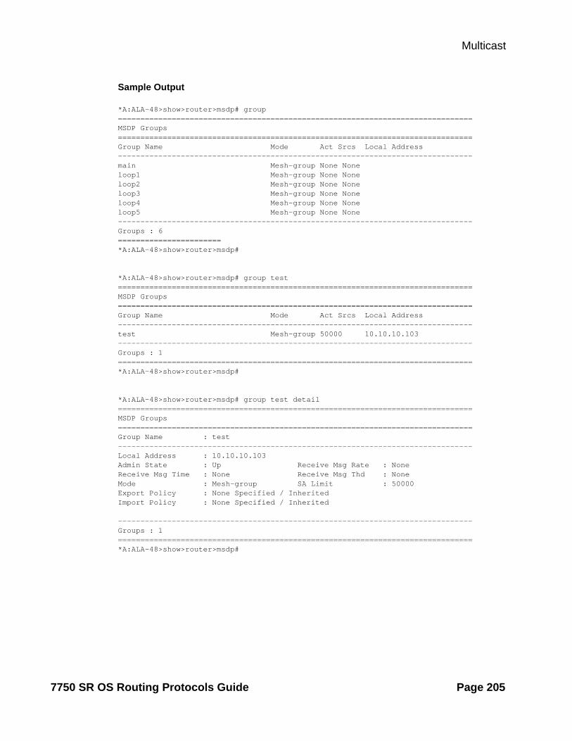
Multicast
Sample Output
*A:ALA-48>show>router>msdp# group===============================================================================MSDP Groups===============================================================================Group Name Mode Act Srcs Local Address -------------------------------------------------------------------------------main Mesh-group None None loop1 Mesh-group None None loop2 Mesh-group None None loop3 Mesh-group None None loop4 Mesh-group None None loop5 Mesh-group None None -------------------------------------------------------------------------------Groups : 6=======================*A:ALA-48>show>router>msdp#
*A:ALA-48>show>router>msdp# group test===============================================================================MSDP Groups===============================================================================Group Name Mode Act Srcs Local Address-------------------------------------------------------------------------------test Mesh-group 50000 10.10.10.103-------------------------------------------------------------------------------Groups : 1===============================================================================*A:ALA-48>show>router>msdp#
*A:ALA-48>show>router>msdp# group test detail===============================================================================MSDP Groups===============================================================================Group Name : test-------------------------------------------------------------------------------Local Address : 10.10.10.103Admin State : Up Receive Msg Rate : NoneReceive Msg Time : None Receive Msg Thd : NoneMode : Mesh-group SA Limit : 50000Export Policy : None Specified / InheritedImport Policy : None Specified / Inherited
-------------------------------------------------------------------------------Groups : 1===============================================================================*A:ALA-48>show>router>msdp#
7750 SR OS Routing Protocols Guide Page 205

Show Router PIM Commands
peer
Syntax peer [ip-address] [group group-name] [detail]
Context show>router>msdp
Description This command displays information about an MSDP peer.
Parameters ip-address — Displays information about the specified IP address. If no IP address specified, information about all MSDP IP addresses display.
group group-name — Displays information about the specified group name. If no group-name is specified, information about all MSDP peers display.
detail — Displays detailed MSDP peer infomration.
Output MSDP Peer Output — The following table provides MSDP field descriptions.
Label Description
Peer Displays the IP address of the peer.
Local Address Displays the local IP address.
State Displays the current state of the peer.
Last State Change
Displays the date and time of the peer’s last state change.
SA Learn The number of SAs learned through a peer.
Sample Output
A:ALA-48# show router msdp peer=============================================================================MSDP Peers=============================================================================Peer Local Address State Last State Change SA Learnt-----------------------------------------------------------------------------10.20.1.1 10.20.1.6 Established 08/30/2002 03:22:131008 -----------------------------------------------------------------------------Peers : 1=============================================================================A:ALA-48#
A:ALA-48# show router msdp peer detail===============================================================================MSDP Peers-------------------------------------------------------------------------------Peer Address : 10.20.1.1 -------------------------------------------------------------------------------Group Name : None Local Address : 10.20.1.6 Last State Change : 08/30/2002 03:22:13 Last Act Src Limit : N/APeer Admin State : Up Default Peer : No Peer Connect Retry : 0 State : Established
Page 206 7750 SR OS Routing Protocols Guide

Multicast
SA accepted : 1008 SA received : 709 State timer expires: 18 Peer time out : 62 Active Source Limit: None Receive Msg Rate : 0 Receive Msg Time : 0 Receive Msg Thd : 0 Auth Status : Disabled Auth Key : None Export Policy : None Specified / InheritedImport Policy : None Specified / Inherited-------------------------------------------------------------------------------Peers : 1===============================================================================A:ALA-48#
source
Syntax source [ip-address/mask] [type {configured | dynamic | both}] [detail]
Context show>router>msdp
Description This command displays the discovery method for this multicast source.
Parameters configured — Displays user-created sources.
dynamic — Displays dynamically created sources.
both — Displays both user-configured and dynamically created sources.
detail — Displays detailed MSDP source information.
Output MSDP Source Output — The following table provides MSDP source field descriptions.
Label Description
Source Displays the IP address of the peer.
Type Displays the type of peer.
SA limit Displays the local IP address.
State Displays the current state of the peer.
Num excd Indicates the number of times the global active source limit has been exceeded.
Last exceeded Displays the date and time of the peer’s last state change.
source-active
Syntax source-active [group ip-address | local | originator ip-address | peer ip-address | source ip-address |{group ip-address source ip-address}][detail]
Context show>router>msdp
Description This command displays source active messages accepted by MSDP.
7750 SR OS Routing Protocols Guide Page 207

Show Router PIM Commands
Parameters group ip-address — Displays information about the specified group IP address.
local — Displays information about local source-active messages.
originator ip-address — Displays information about the specified originator IP address.
peer ip-address — Displays information about the specified peer IP address.
source ip-address — Displays information about the specified source IP address.
group ip-address — Displays information about the specified group IP address.
detailDisplays detailed MSDP source-active information.
Output MSDP Source-Active Output — The following table provides MSDP source-active field descriptions.
Label Description
Grp Address Displays the IP address of the group.
Src Address Displays the IP address of the source.
Origin RP Displays the origination rendezvous point (RP) address.
Peer Address Displays the address of the peer.
State Timer The time-out value. If the value reaches zero, the SA is removed.
Sample Output
A:ALA-48# show router msdp source-active===============================================================================MSDP Source Active Info===============================================================================Grp Address Src Address Origin RP Peer Address State Timer-------------------------------------------------------------------------------228.100.0.0 100.112.1.2 10.20.1.1 10.20.1.1 69 228.100.0.1 100.112.1.2 10.20.1.1 10.20.1.1 69 228.100.0.2 100.112.1.2 10.20.1.1 10.20.1.1 69 228.100.0.3 100.112.1.2 10.20.1.1 10.20.1.1 69 228.100.0.4 100.112.1.2 10.20.1.1 10.20.1.1 69 228.100.0.5 100.112.1.2 10.20.1.1 10.20.1.1 69 228.100.0.6 100.112.1.2 10.20.1.1 10.20.1.1 69 228.100.0.7 100.112.1.2 10.20.1.1 10.20.1.1 69 228.100.0.8 100.112.1.2 10.20.1.1 10.20.1.1 69 228.100.0.9 100.112.1.2 10.20.1.1 10.20.1.1 69 -------------------------------------------------------------------------------MSDP Source Active : 10===============================================================================A:ALA-48#
A:ALA-48# show router msdp source-active detail===============================================================================MSDP Source Active===============================================================================Group Address : 228.100.0.0 Source Address : 100.112.1.2 Origin RP : 10.20.1.1 Peer Address : 10.20.1.1 State Timer : 64 Up Time : 3d 01:44:25
Page 208 7750 SR OS Routing Protocols Guide

Multicast
Group Address : 228.100.0.1 Source Address : 100.112.1.2 Origin RP : 10.20.1.1 Peer Address : 10.20.1.1 State Timer : 64 Up Time : 48d 18:22:29 Group Address : 228.100.0.2 Source Address : 100.112.1.2 Origin RP : 10.20.1.1 Peer Address : 10.20.1.1 State Timer : 64 Up Time : 48d 18:22:29 Group Address : 228.100.0.3 Source Address : 100.112.1.2 Origin RP : 10.20.1.1 Peer Address : 10.20.1.1 State Timer : 64 Up Time : 48d 18:22:29 Group Address : 228.100.0.4 Source Address : 100.112.1.2 Origin RP : 10.20.1.1 Peer Address : 10.20.1.1 State Timer : 64 Up Time : 48d 18:22:29 Group Address : 228.100.0.5 Source Address : 100.112.1.2 Origin RP : 10.20.1.1 Peer Address : 10.20.1.1 State Timer : 64 Up Time : 48d 18:22:29 Group Address : 228.100.0.6 Source Address : 100.112.1.2 Origin RP : 10.20.1.1 Peer Address : 10.20.1.1 State Timer : 64 Up Time : 48d 18:22:29 Group Address : 228.100.0.7 Source Address : 100.112.1.2 Origin RP : 10.20.1.1 Peer Address : 10.20.1.1 State Timer : 64 Up Time : 48d 18:22:29 Group Address : 228.100.0.8 Source Address : 100.112.1.2 Origin RP : 10.20.1.1 Peer Address : 10.20.1.1 State Timer : 64 Up Time : 48d 18:22:29 Group Address : 228.100.0.9 Source Address : 100.112.1.2 Origin RP : 10.20.1.1 Peer Address : 10.20.1.1 State Timer : 64 Up Time : 48d 18:22:29 -------------------------------------------------------------------------------MSDP Source Active : 10===============================================================================A:ALA-48#
source-active-rejected
Syntax source-active-rejected [peer-group name] [group ip-address] [source ip-address] [originator ip-address] [peer ip-address]
Context show>router>msdp
Description This command displays source active messages rejected by MSDP.
Parameters group ip-address — Displays information about the peer group name of the Source Active entry that is rejected.
local — Displays information about local source-active messages.
originator ip-address — Displays information about the specified originator IP address.
peer ip-address — Displays information about the peer from which this rejected source active entry was last received.
source ip-address — Displays information about the source address of the source active entry that is rejected.
group ip-address — Displays information about the specified group IP address.
7750 SR OS Routing Protocols Guide Page 209

Show Router PIM Commands
MSDP Source-Active Output — The following table provides MSDP source-active field descriptions.
Label Description
Grp Address Displays the IP address of the group.
Src Address Displays the IP address of the source.
Origin RP Displays the origination rendezvous point (RP) address.
Peer Address Displays the address of the peer.
Reject Reason Displays the reason why this source active entry is rejected.
Sample Output
*A:ALA-48# show router msdp source-active-rejected===============================================================================MSDP Source Active Rejected Info===============================================================================Grp Address Src Address Origin RP Peer Address Reject Reason-------------------------------------------------------------------------------228.100.0.1 110.0.0.1 10.20.0.1 20.0.0.1 Import Policy228.100.0.2 110.0.0.2 10.20.0.2 20.0.0.2 Export Policy228.100.0.3 110.0.0.3 10.20.0.3 20.0.0.3 RPF Failure228.100.0.4 110.0.0.4 10.20.0.4 20.0.0.4 Limit Exceeded228.100.0.5 110.0.0.5 10.20.0.5 20.0.0.5 Limit Exceeded228.100.0.6 110.0.0.6 10.20.0.6 20.0.0.6 Limit Exceeded228.100.0.7 110.0.0.7 10.20.0.7 20.0.0.7 Limit Exceeded-------------------------------------------------------------------------------SA Rejected Entries : 7===============================================================================*A:ALA-48#
statistics
Syntax statistics [peer ip-address]
Context show>router>msdp
Description This command displays statistics information related to a MSDP peer.
Parameters peer ip-address — Displays information about the specified peer IP address
Output MSDP Statistics Output — The following table provides MSDP statistics field descriptions.
Label Description
Last State Change Displays the date and time the peer state changed.
RPF Failures Displays the number of reverse path forwarding (RPF) failures.
SA Msgs Sent Displays the number of source-active messages sent.
Page 210 7750 SR OS Routing Protocols Guide

Multicast
Sample Output
A:ALA-48# show router msdp statistics===============================================================================MSDP Statistics===============================================================================Glo ActSrc Lim Excd: 0 -------------------------------------------------------------------------------Peer Address : 10.20.1.1 -------------------------------------------------------------------------------Last State Change : 0d 11:33:16 Last message Peer : 0d 00:00:17 RPF Failures : 0 Remote Closes : 0 SA Msgs Sent : 0 SA Msgs Recvd : 709 SA req. Msgs Sent : 0 SA req. Msgs Recvd : 0 SA res. Msgs Sent : 0 SA res. Msgs Recvd : 0 KeepAlive Msgs Sent: 694 KeepAlive Msgs Recd: 694 Unknown Msgs Sent : 0 Error Msgs Recvd : 0 -------------------------------------------------------------------------------Peers : 1===============================================================================A:ALA-48#
SA req. Msgs Sent Displays the number of source-active request messages sent.
SA res. Msgs Sent Displays the number of source-active response messages sent.
KeepAlive Msgs Sent
Displays the number of keepalive messages sent.
Unknown Msgs Sent Displays the number of unknown messages received.
Last message Peer Displays the time the last message was received from the peer.
Remote Closes Displays the number of times the remote peer close.
SA Msgs Recvd Displays the number of source-active messages received.
SA req. Msgs Recvd Displays the number of source-active request messages received.
SA res. Msgs Recvd Displays the number of source-active response messages received.
KeepAlive Msgs Recd
Displays the number of keepalive messages received.
Error Msgs Recvd Displays the number of unknown messages received.
Label Description (Continued)
7750 SR OS Routing Protocols Guide Page 211

Show Router PIM Commands
status
Syntax status
Context show>router>msdp
Description This command displays MSDP status information.
Output MSDP Status Output — The following table provides MSDP status field descriptions.
Label Description
Admin State Displays the administrative state.
Local Address Displays the local IP address.
Active Src Limit Displays the active source limit.
Act Src Lim Excd Displays the active source limit which has been exceeded.
Num. Peers Displays the number of peers.
Num. Peers Estab Displays the number of peers established.
Num. Source Active
Displays the number of active sources.
Policies The policy to export source active state from the source active list into MSDP.
Data Encapsula-tion
The rendezvous point (RP) using MSDP to encapsulate multicast data received in MSDP register messages inside forwarded MSDPsource-active messages - enabled or disabled.
Rate The receive message rate.
Time The receive message time.
Threshold The number of MSDP messages that can be processed before the MSDP message rate limiting function is activated.
RPF Table The name of the reverse path forwarding table.
Last mdsp Enabled
The time the last MDSP was triggered.
Sample Output
A:ALA-48# show router msdp status ===============================================================================MSDP Status===============================================================================Admin State : Up Local Address : None Global StatisticsActive Src Limit : None
Page 212 7750 SR OS Routing Protocols Guide

Multicast
Act Src Lim Excd : 0 Num. Peers : 1 Num. Peers Estab : 1 Num. Source Active : 10 Policies : NoneData Encapsulation : Enabled Receive Msg RateRate : 0 Time : 0 Threshold : 0 Last Msdp Enabled : 08/30/2002 03:21:43===============================================================================A:ALA-48#
mcac
Syntax mcac
Context show>router
Description This command enables the context to display multicast CAC related information.
policy
Syntax policy [policy-name [bundle bundle-name] [protocol protocol-name] [interface if-name] [detail]]
Context show>router>mcac
Description This command displays MCAC policy information.
Parameters policy-name — Specifies an existing multicast CAC (MCAC) policy name.
bundle bundle-id — Specifies an existing multicast bundle name.
protocol protocol-name — specifies an applicable protocol to display.
Values igmp, pim, igmpSnpg
interface if-name — Specifies an interface name to display.
detail — Displays detailed information.
Sample Output
*A:ALA-48>show>router>mcac# policy===============================================================================Multicast CAC Policies===============================================================================Policy Description-------------------------------------------------------------------------------btv_fr foreign TV offeringbtv_vl eastern TV offeringpolicy1 this is policy1
7750 SR OS Routing Protocols Guide Page 213
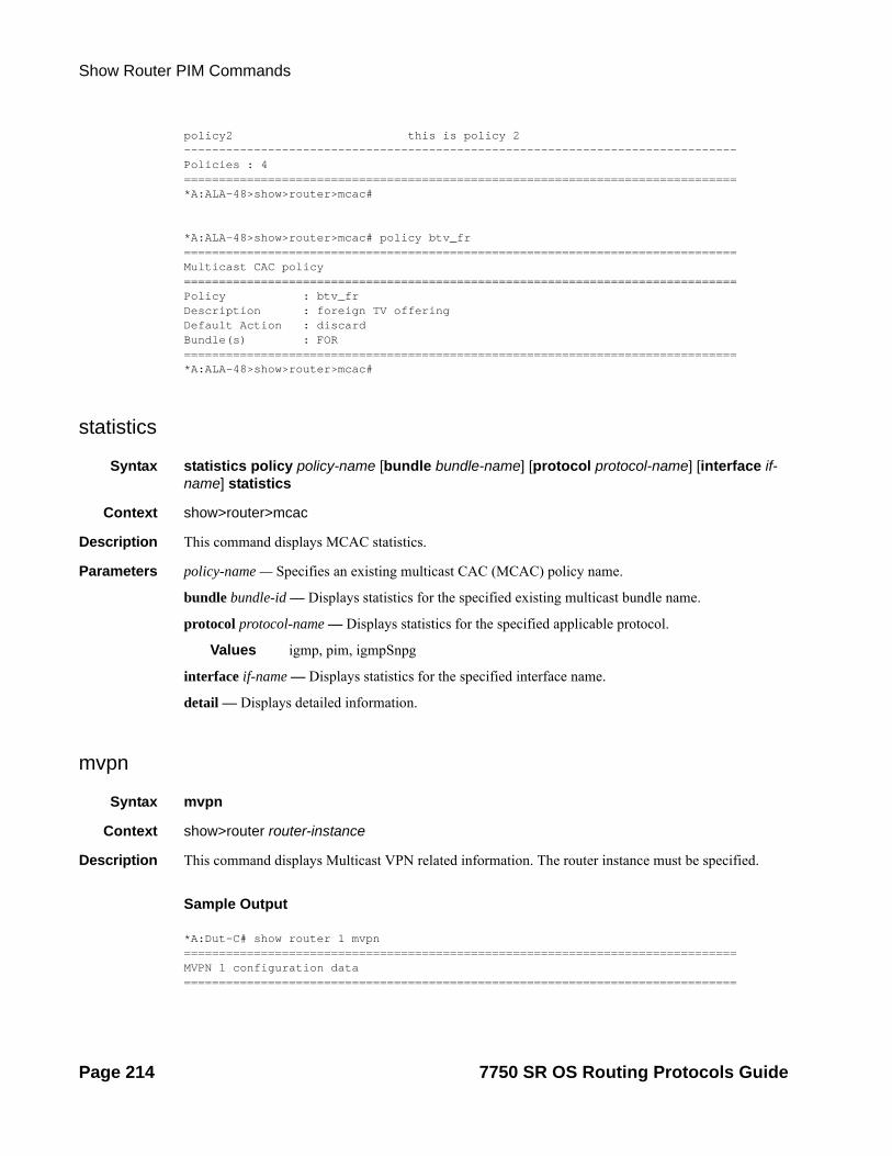
Show Router PIM Commands
policy2 this is policy 2-------------------------------------------------------------------------------Policies : 4===============================================================================*A:ALA-48>show>router>mcac#
*A:ALA-48>show>router>mcac# policy btv_fr===============================================================================Multicast CAC policy===============================================================================Policy : btv_frDescription : foreign TV offeringDefault Action : discardBundle(s) : FOR===============================================================================*A:ALA-48>show>router>mcac#
statistics
Syntax statistics policy policy-name [bundle bundle-name] [protocol protocol-name] [interface if-name] statistics
Context show>router>mcac
Description This command displays MCAC statistics.
Parameters policy-name — Specifies an existing multicast CAC (MCAC) policy name.
bundle bundle-id — Displays statistics for the specified existing multicast bundle name.
protocol protocol-name — Displays statistics for the specified applicable protocol.
Values igmp, pim, igmpSnpg
interface if-name — Displays statistics for the specified interface name.
detail — Displays detailed information.
mvpn
Syntax mvpn
Context show>router router-instance
Description This command displays Multicast VPN related information. The router instance must be specified.
Sample Output
*A:Dut-C# show router 1 mvpn===============================================================================MVPN 1 configuration data===============================================================================
Page 214 7750 SR OS Routing Protocols Guide

Multicast
signaling : Bgp auto-discovery : EnabledUMH Selection : Highest-Ip intersite-shared : Enabledvrf-import : N/Avrf-export : N/Avrf-target : target:1:1C-Mcast Import RT : target:10.20.1.3:2 ipmsi : pim-asm 224.1.1.1admin status : Up three-way-hello : N/Ahello-interval : N/A hello-multiplier : 35 * 0.1tracking support : Disabled Improved Assert : N/A spmsi : pim-ssm 225.0.0.0/32join-tlv-packing : N/Adata-delay-interval: 3 secondsdata-threshold : 224.0.0.0/4 --> 1 kbps===============================================================================
tunnel-table
Syntax tunnel-table [ip-address [/mask]] [protocol | sdp sdp-id]tunnel-table [summary]
Context show>router
Description This command displays tunnel table information.
Parameters protocol — Specifies the protocol.
Values bgp | ldp | rsvp | sdp
sdp-id — Specifies the SDP ID.
Values 1..17407
Output *A:Dut-C# show router tunnel-table sdp 17407 ========================================================================Tunnel Table (Router: Base)
========================================================================
Destination Owner Encap TunnelId Pref Nexthop Metric
------------------------------------------------------------------------
127.0.68.0/32 sdp MPLS 17407 5 127.0.68.0 0
========================================================================
7750 SR OS Routing Protocols Guide Page 215

Clear Commands
Clear Commands
database
Syntax database [interface ip-int-name|ip-address] group grp-ip-address [source src-ip-address]database grp-interface interface-name [fwd-service service-id]database [interface ip-int-name|ip-address] group grp-ip-address source src-ip-addressdatabase host [ip-address]database interface ip-int-name|ip-address [group grp-ip-address] [source src-ip-address]
Context clear>router>igmp
Description This command clears IGMP or PIM database statistics on a specified interface or IP address.
Parameters interface ip-int-name — Clears the IGMP or PIM database on the specified interface.
interface ip-address — Clears the IGMP or PIM database on the specified IP address.
group group-ip-address — Clears the multicast group address(ipv4/ipv6) or zero in the specified address group.
source ip-address — Clears the IGMP or PIM database from the specified source IP address.
database
Syntax database [interface ip-int-name|mt-int-name|int-ip-address] [group grp-ip-address [source ip-address]] [family]
Context clear>router>pim
Description This command clears IGMP or PIM database statistics on a specified interface or IP address.
Parameters interface ip-int-name — Clears the IGMP or PIM database on the specified interface.
interface mt-int-name — Clears the default core group address of the Multicast Distribution Tree (MDT) for the VPRN instance. The Multicast Tunnel (MT) interface for a VPRN is created when this object is set to a valid group address.
Syntax: vprn-id-mt-grp-ip-address
interface ip-address — Clears the IGMP or PIM database on the specified IP address.
group group-ip-address — Clears the multicast group address(ipv4/ipv6) or zero in the specified address group.
source ip-address — Clears the IGMP or PIM database from the specified source IP address.
family — Clears either IPv4 or IPv6 information.
mpls-if-name — Clears the MPLS interface name.
Page 216 7750 SR OS Routing Protocols Guide

Multicast
Syntax: mpls-if-index
statistics
Syntax statistics [interface ip-int-name | ip-address]
Context clear>router>igmp
Description This command clears IGMP statistics on a specified interface or IP address.
Note that interface and group/source cannot be specified at the same time.
Parameters interface ip-int-name — Clears IGMP statistics on the specified interface.
interface ip-address — Clears IGMP statistics on the specified IP address.
interface mt-int-name — Clears the default core group address of the Multicast Distribution Tree (MDT) for the VPRN instance. The Multicast Tunnel (MT) interface for a VPRN is created when this object is set to a valid group address.
Syntax: vprn-id-mt-grp-ip-address
s-pmsi
Syntax s-pmsi [mdSrcAddr] [mdGrpAddr] [vprnSrcAddr vprnGrpAddr]
Context clear>router>pim
Description This command clears PIM selective provider multicast service interface cache.
Parameters mdSrcAddr — Clears the specified source address used for Multicast Distribution Tree (MDT).
mdGrpAddr — Clears the specified group address used for Multicast Distribution Tree (MDT).
vprnSrcAddr — Clears the specified source address of the multicast sender.
vprnGrpAddr — Clears the specified multicast group address.
statistics
Syntax statistics [{[interface ip-int-name | ip-address | mt-int-name]} {[group grp-ip-address [source ip-address]]}] [family]]
Context clear>router>pim
Description This command clears PIM statistics on a specified interface or IP address.
Note that an interface and group or source cannot be specified at the same time.
Parameters interface ip-int-name — Clears PIM statistics on the specified interface.
interface ip-address — Clears PIM statistics on the specified IP address.
7750 SR OS Routing Protocols Guide Page 217

Clear Commands
interface mt-int-name — Clears the default core group address of the Multicast Distribution Tree (MDT) for the VPRN instance. The Multicast Tunnel (MT) interface for a VPRN is created when this object is set to a valid group address.
syntax: vprn-id-mt-grp-ip-address
group grp-ip-address — When only the group address is specified and no source is specified, (*,G) statistics are cleared. When the group address is specified along with the source address, then the (S,G) statistics are reset to zero.
source ip-address — When the source address is specified along with the group address, then the (S,G) statistics are reset to zero.
family — Clears either IPv4 or IPv6 information.
version
Syntax version [interface ip-int-name | ip-address]
Context clear>router>igmp
Description This command clears IGMP statistics on a specified interface or IP address.
Parameters interface ip-int-name — Clears IGMP or PIM statistics on the specified interface.
interface ip-address — Clears IGMP or PIM statistics on the specified IP address.
mld
Syntax mld
Context clear>router
Description This command enables the context to to clear and reset Multicast Listener Discovery (MLD) entities.
database
Syntax database [interface ip-int-name|ipv6-address] [group ip-address [source ip-address]]
Context clear>router>mld
Description This command clears Multicast Listener Discovery (MLD) database parameters.
Parameters interface ip-int-name — Clears database information for the specified Multicast Listener Discovery (MLD) interface name.
interface ipv6-address — Clears database information for the specified Multicast Listener Discovery (MLD) interface IPv6 address.
Page 218 7750 SR OS Routing Protocols Guide

Multicast
group ip-address — Clears database information for the specified Multicast Listener Discovery (MLD) group IP address.
source ip-address — Clears database information for the specified Multicast Listener Discovery (MLD) source IP address.
statistics
Syntax statistics [ip-int-name|ipv6-address]
Context clear>router>mld
Description This command clears Multicast Listener Discovery (MLD) statistics parameters.
Parameters ip-int-name — Clears statistics for the specified Multicast Listener Discovery (MLD) interface name.
ipv6-address — Clears statistics for the specified Multicast Listener Discovery (MLD) IPv6 address.
version
Syntax version [ip-int-name|ip-address]
Context clear>router>mld
Description This command clears Multicast Listener Discovery (MLD) version parameters.
Parameters ip-int-name — Clears version information for the specified Multicast Listener Discovery (MLD) interface name.
ip-address — Clears version information for the specified Multicast Listener Discovery (MLD) IP address.
msdp
Syntax msdp
Context clear>router
Description This command enables the context to clear and reset Multicast Source Discovery protocol (MSDP) entities and statistics.
cache
Syntax cache [peer ip-address] [group ip-address] [source ip-address] [originrp ip-address]
Context clear>router>msdp
Description This command clears the MSDP cache.
7750 SR OS Routing Protocols Guide Page 219

Clear Commands
Parameters peer ip-address — Clears the cache of the IP address of the peer to which Multicast Source Discovery protocol (MSDP) source-active ( SA) requests for groups matching this entry's group range were sent.
group ip-address — Clears the group IP address of the SA entry.
source ip-address — Clears the source IP address of the SA entry.
originrp ip-address — Clears the origin rendezvous point(RP) address type of the SA entry.
statistics
Syntax statistics [peer ip-address]
Context clear>router>msdp
Description peer ip-address — Clears the statistics of the IP address of the peer to which Multicast Source Discovery Protocol (MSDP) source-active ( SA) requests for groups matching this entry's group range were sent.
neighbor
Syntax neighbor [ip-int-name | ip-address] [family]
Context clear>router>pim
Description This command clears PIM neighbor data on a specified interface or IP address.
Parameters ip-int-name — Clears PIM neighbor on the specified interface.
ip-address — Clears PIM neighbor on the specified IP address.
family — Clears either IPv4 or IPv6 information.
igmp-snooping
Syntax igmp-snooping
Context clear>service>id
Description This command enables the context to clear IGMP snooping-related data.
port-db
Syntax port-db {sap sap-id | sdp sdp-id:vc-id} [group grp-address [source ip-address]]
Context clear>service>id>igmp-snooping
Description Clears the information on the IGMP snooping port database.
Page 220 7750 SR OS Routing Protocols Guide

Multicast
Parameters sap sap-id — Clears IGMP snooping statistics matching the specified SAP ID and optional encapsulation value. The sap-id can be in one of the following formats:
Encapsulation type Syntax Example
null port-id 1/1/3
dot1q port-id :qtag1 1/1/3:100
qinq port-id :qtag1.qtag2 1/1/3:100.200
qtag1, qtag2 — The encapsulation value on the specified port ID.
Values 0 — 4094
sdp sdp-id — Clears only IGMP snooping entries associated with the specified mesh SDP or spoke SDP. For a spoke SDP, the VC ID must be specified; for a mesh SDP, the VC ID is optional.
Values 1 — 17407
vc-id — The virtual circuit ID on the SDP ID for which to clear information.
Default For mesh SDPs only, all VC IDs
Values 1 — 4294967295
group grp-address — Clears IGMP snooping statistics matching the specified group address.
source ip-address — Clears IGMP snooping statistics matching one particular source within the multicast group.
querier
Syntax querier
Context clear>service>id>igmp-snooping
Description Clears information on the IGMP snooping queriers for the VPLS service.
statistics
Syntax statistics [sap sap-id | sdp sdp-id:vc-id]
Context clear>service>id>igmp-snooping
Description Clears IGMP snooping statistics for the VPLS service.
Parameters sap sap-id — Displays IGMP snooping statistics for a specific SAP. The sap-id can be in one of the following formats:
Encapsulation type Syntax Example
null port-id 1/1/3
dot1q port-id :qtag1 1/1/3:100
qinq port-id :qtag1.qtag2 1/1/3:100.200
7750 SR OS Routing Protocols Guide Page 221

Clear Commands
qtag1, qtag2 — The encapsulation value on the specified port ID.
Values 0 — 4094
sdp sdp-id — Displays the IGMP snooping statistics for a specific spoke or mesh SDP.
Values 1 — 17407
vc-id — The virtual circuit ID on the SDP ID for which to display information.
Default For mesh SDPs only, all VC IDs
Values 1 — 4294967295
pim-snooping
Syntax pim-snooping
Context clear>service>id
Description This command enables the context to clear PIM snooping information.
database
Syntax database [[sap sap-id | sdp sdp-id:vc-id] [group grp-ip-address] [source src-ip-address]]
Context clear>service>id>pim-snooping
Description This command clears PIM snooping source group database information.
Parameters sap sap-id — Clears PIM snooping SAP information.
sdp sdp-id — Clears PIM snooping entries associated with the specified SDP. For a spoke SDP, the VC ID must be specified; for a mesh SDP, the VC ID is optional.
Values 1 — 17407
group grp-address — Clears PIM snooping information matching the specified group address.
source ip-address — Clears PIM snooping information matching one particular source within the multicast group.
neighbor
Syntax neighbor [ip-address | sap sap-id | sdp sdp-id:vc-id]
Context clear>service>id>pim-snooping
Description This comand clears PIM snooping neighbor information.
Parameters ip-address — Clears IP address information.
Page 222 7750 SR OS Routing Protocols Guide

Multicast
sap sap-id — Clears PIM snooping SAP information.
sdp sdp-id — Clears PIM snooping entries associated with the specified SDP. For a spoke SDP, the VC ID must be specified; for a mesh SDP, the VC ID is optional.
Values 1 — 17407
statistics
Syntax statistics [sap sap-id | sdp sdp-id:vc-id]
Context clear>service>id>pim-snooping
Description This command cloears PIM snooping statistics for the specified SAP or SDP.
Parameters sap sap-id — Clears PIM snooping SAP information.
sdp sdp-id — Clears PIM snooping entries associated with the specified SDP. For a spoke SDP, the VC ID must be specified; for a mesh SDP, the VC ID is optional.
Values 1 — 17407
7750 SR OS Routing Protocols Guide Page 223
Debug Commands
Debug Commands
Debug IGMP Commands
group-interface
Syntax [no] group-interface [fwd-service service-id] [ip-int-name]
Context debug>router>igmp
Description This command enables debugging for IGMP group-interface.
The no form of the command disables debugging.
host
Syntax host [ip-address]host [fwd-service service-id] group-interface ip-int-nameno host [ip-address]no host [fwd-service service-id] group-interface ip-int-name
Context debug>router>igmp
Description This command enables debugging for the IGMP host.
The no form of the command disables debugging.
interface
Syntax [no] interface [ip-int-name | ip-address]
Context debug>router>igmp
Description This command enables debugging for IGMP interfaces.
The no form of the command disables the IGMP interface debugging for the specifies interface name or IP address.
Parameters ip-int-name — Only displays the information associated with the specified IP interface name.
ip-address — Only displays the information associated with the specified IP address.
Page 224 7750 SR OS Routing Protocols Guide
Multicast
mcs
Syntax mcs [ip-int-name]no mcs
Context debug>router>igmp
Description This command enables debugging for IGMP multicast servers (MCS).
The no form of the command disables the IGMP interface debugging for the specifies interface name.
Parameters ip-int-name — Only displays the information associated with the specified IP interface name.
misc
Syntax [no] misc
Context debug>router>igmp
Description This command enables debugging for IGMP miscellaneous.
The no form of the command disables the debugging.
Sample Output
A:ALA-CA# debug router 100 igmp misc *A:ALA-CA# show debug debug router "100" igmp misc exit exitexit*A:ALA-CA#
packet
Syntax packet [query|v1-report|v2-report|v3-report|v2-leave] host ip-addresspacket [query|v1-report|v2-report|v3-report|v2-leave] [ip-int-name|ip-address]no packet [query|v1-report|v2-report|v3-report|v2-leave] [ip-int-name|ip-address]no packet [query|v1-report|v2-report|v3-report|v2-leave] host ip-address
Context debug>router>igmp
Description This command enables/disables debugging for IGMP packets.
Parameters query — Specifies to log the IGMP group- and source-specific queries transmitted and received on this interface.
v1-report — Specifies to log IGMP V1 reports transmitted and received on this interface.
7750 SR OS Routing Protocols Guide Page 225

Debug Commands
v2-report — Specifies to log IGMP V2 reports transmitted and received on this interface.
v3-report — Specifies to log IGMP V3 reports transmitted and received on this interface.
v2-leave — Specifies to log the IGMP Leaves transmitted and received on this interface.
ip-int-name — Only displays the information associated with the specified IP interface name.
ip-address — Only displays the information associated with the specified IP address.
Page 226 7750 SR OS Routing Protocols Guide

Multicast
Debug PIM Commands
adjacency
Syntax [no] adjacency
Context debug>router>pim
Description This command enables/disables debugging for PIM adjacencies.
all
Syntax all [group grp-ip-address] [source ip-address] [detail]no all
Context debug>router>pim
Description This command enables/disables debugging for all the PIM modules.
Parameters group grp-ip-address — Debugs information associated with all PIM modules.
Values IPv4 or IPv6 address
source ip-address — Debugs information associated with all PIM modules.
Values IPv4 or IPv6 address
detail — Debugs detailed information on all PIM modules.
assert
Syntax assert [group grp-ip-address] [source ip-address] [detail]no assert
Context debug>router>pim
Description This command enables/disables debugging for PIM assert mechanism.
Parameters group grp-ip-address — Debugs information associated with the PIM assert mechanism.
Values multicast group address (ipv4/ipv6)
source ip-address — Debugs information associated with the PIM assert mechanism.
Values source address (ipv4/ipv6)
detail — Debugs detailed information on the PIM assert mechanism.
7750 SR OS Routing Protocols Guide Page 227

Debug Commands
bsr
Syntax bsr [detail]no bsr
Context debug>router>pim
Description This command enables debugging for PIM Bootstrap mechanism.
The no form of the command disables debugging.
Parameters detail — Debugs detailed information on the PIM assert mechanism.
data
Syntax data [group grp-ip-address] [source ip-address] [detail]no data
Context debug>router>pim
Description This command enables/disables debugging for PIM data exception.
Parameters group grp-ip-address — Debugs information associated with the specified data exception.
Values multicast group address (ipv4/ipv6)
source ip-address — Debugs information associated with the specified data exception.
Values source address (ipv4/ipv6)
detail — Debugs detailed IP data exception information.
db
Syntax db [group grp-ip-address] [source ip-address] [detail]no db
Context debug>router>pim
Description This command enables/disables debugging for PIM database.
Parameters group grp-ip-address — Debugs information associated with the specified database.
Values multicast group address (ipv4/ipv6) or zero
source ip-address — Debugs information associated with the specified database.
Values source address (ipv4/ipv6)
detail — Debugs detailed IP database information.
Page 228 7750 SR OS Routing Protocols Guide

Multicast
interface
Syntax interface [ip-int-name | mt-int-name | ip-address] [detail]no interface
Context debug>router>pim
Description This command enables/disables debugging for PIM interface.
Parameters ip-int-name — Debugs the information associated with the specified IP interface name.
Values IPv4 or IPv6 interface address
mt-int-address — Debugs the information associated with the specified VPRN ID and group address.
ip-address — Debugs the information associated with the specified IP address.
detail — Debugs detailed IP interface information.
jp
Syntax jp [group grp-ip-address] [source ip-address] [detail]no jp
Context debug>router>pim
Description This command enables/disables debugging for PIM Join-Prune mechanism.
Parameters group grp-ip-address — Debugs information associated with the specified Join-Prune mechanism.
Values multicast group address (ipv4/ipv6) or zero
source ip-address — Debugs information associated with the specified Join-Prune mechanism.
Values source address (ipv4/ipv6)
detail — Debugs detailed Join-Prune mechanism information.
mrib
Syntax mrib [group grp-ip-address] [source ip-address] [detail]no mrib
Context debug>router>pim
Description This command enables/disables debugging for PIM MRIB.
Parameters group grp-ip-address — Debugs information associated with the specified PIM MRIB.
Values multicast group address (ipv4/ipv6)
source ip-address — Debugs information associated with the specified PIM MRIB.
Values source address (ipv4/ipv6)
7750 SR OS Routing Protocols Guide Page 229

Debug Commands
detail — Debugs detailed MRIB information.
msg
Syntax msg [detail]no msg
Context debug>router>pim
Description This command enables/disables debugging for PIM messaging.
Parameters detail — Debugs detailed messaging information.
packet
Syntax packet [hello | register | register-stop | jp | bsr | assert | crp] [ip-int-name | ip-address]no packet
Context debug>router>pim
Description This command enables/disables debugging for PIM packets.
Parameters hello | register | register-stop | jp | bsr | assert | crp — PIM packet types.
ip-int-name — Debugs the information associated with the specified IP interface name.
Values IPv4 or IPv6 interface address
ip-address — Debugs the information associated with the specified IP address of a particular packet type.
register
Syntax register [group grp-ip-address] [source ip-address] [detail]no register
Context debug>router>pim
Description This command enables/disables debugging for PIM Register mechanism.
Parameters group grp-ip-address — Debugs information associated with the specified PIM register.
Values multicast group address (ipv4/ipv6)
source ip-address — Debugs information associated with the specified PIM register.
Values source address (ipv4/ipv6)
detail — Debugs detailed register information.
Page 230 7750 SR OS Routing Protocols Guide

Multicast
rtm
Syntax rtm [detail]no rtm
Context debug>router>pim
Description This command enables/disables debugging for PIM RTM.
Parameters detail — Debugs detailed RTM information.
s-pmsi
Syntax s-pmsi [{vpnSrcAddr [vpnGrpAddr]} [mdSrcAddr]] [detail]no s-pmsi
Context debug>router>pim
Description This command enables debugging for PIM selective provider multicast service interface.
The no form of the command disables the debugging.
Parameters vpnSrcAddr — Specifies the VPN source address.
vpnGrpAddr — Specifies the VPN group address
mdSrcAddr — Specifies the source address of the multicast sender.
detail — Displays detailed information for selective PMSI.
msdp
Syntax [no] msdp
Context debug>router
Description This command enables debugging for Multicast Source Discovery Protocol (MSDP).
The no form of the command disables MSDP debugging.
packet
Syntax packet [pkt-type] [peer ip-address]
Context debug>router>msdp
Description This command enables debugging for Multicast Source Discovery Protocol (MSDP) packets.
The no form of the command disables MSDP packet debugging.
7750 SR OS Routing Protocols Guide Page 231

Debug Commands
Parameters pkt-type — Debugs information associated with the specified packet type.
Values keep-alive, source-active, sa-request, sa-response
peer ip-address — Debugs information associated with the specified peer IP address.
pim
Syntax pim [grp-address]no pim
Context debug>router>msdp
Description This command enables debugging for Multicast Source Discovery Protocol (MSDP) PIM.
The no form of the command disables MSDP PIM debugging.
Parameters grp-address — Debugs the IP multicast group address for which this entry contains information.
rtm
Syntax rtm [rp-address]no rtm
Context debug>router>msdp
Description This command enables debugging for Multicast Source Discovery Protocol (MSDP) route table manager (RTM).
The no form of the command disables MSDP RTM debugging.
Parameters rp-address — Debugs the IP multicast address for which this entry contains information.
sa-db
Syntax sa-db [group grpAddr] [source srcAddr] [rp rpAddr]no sadb
Context debug>router>msdp
Description This command enables debugging for Multicast Source Discovery Protocol (MSDP) source-active requests.
The no form of the command disables the MSDP source-active database debugging.
Parameters group grpAddr — Debugs the IP address of the group.
source srcAddr — Debugs the source IP address.
rp rpAddr — Debugs the specified rendezvous point RP address.
Page 232 7750 SR OS Routing Protocols Guide

RIP
In This Chapter
This chapter provides information about configuring Routing Information Protocol (RIP) parameters.
Topics in this chapter include:
• RIP Overview on page 234
RIP Features on page 235
RIP Version Types on page 235
RIPv2 Authentication on page 235
Metrics on page 236
Timers on page 236
Import and Export Policies on page 236
RIP Packet Format on page 237
• RIP Configuration Process Overview on page 240
• Configuration Notes on page 241
7750 SR OS Routing Protocols Guide Page 233

RIP Overview
RIP Overview
The Routing Information Protocol (RIP) is an interior gateway protocol (IGP) that uses a distance-vector algorithm to determine the best route to a destination, using hop count as the metric. In order for the protocol to provide complete information on routing, every router in the domain must participate in the protocol.
RIP is a routing protocol based on a distance vector (Bellman-Ford) algorithm, which advertises network reachability by advertising prefix/mask and the metric (also known as hop count or cost). RIP selects the route with the lowest metric as the best route. RIP differs from link-state database protocols, such as OSPF and IS-IS, in that RIP advertises reachability information directly and link-state-database-based protocols advertise topology information. Each node is responsible for calculating the reachability information from the topology.
7750 SR OS software supports RIPv1 and RIPv2. RIPv1, specified in RFC 1058, was written and implemented prior to the introduction of CIDR. It assumes the netmask information for non-local routes, based on the class the route belongs to:
• Class A – 8 bit mask
• Class B – 16 bit mask
• Class C – 24 bit mask
RIPv2 was written after CIDR was developed and transmits netmask information with every route. Because of the support for CIDR routes and other enhancements in RIPv2 such as triggered updates, multicast advertisements, and authentication, most production networks use RIPv2. However, there are some older systems (hosts and routers) that only support RIPv1, especially when RIP is used simply to advertise default routing information.
RIP is supported on all IP interfaces, including both network and access interfaces.
Page 234 7750 SR OS Routing Protocols Guide

RIP
RIP Features
RIP, a UDP-based protocol, updates its neighbors, and the neighbors update their neighbors, and so on. Each host that uses RIP has a routing process that sends and receives datagrams on UDP port number 520.
Each RIP router advertises all RIP routes periodically via RIP updates. Each update can contain a maximum of 25 route advertisements. This limit is imposed by RIP specifications. RIP can sometimes be configured to send as many as 255 routes per update. The formats of the RIPv1 and RIPv2 updates are slightly different and are shown below. Additionally, RIPv1 updates are sent to a broadcast address, RIPv2 updates can be either sent to a broadcast or multicast address (224.0.0.9). RIPv2 supports subnet masks, a feature that was not available in RIPv1.
A network address of 0.0.0.0 is considered a default route. A default route is used when it is not convenient to list every possible network in the RIP updates, and when one or more closely-connected gateways in the system are prepared to handle traffic to the networks that are not listed explicitly. These gateways create RIP entries for the address 0.0.0.0, as if it were a network to which they are connected.
RIP Version Types
7750 SR OS allows you to specify the RIP version that will be sent to RIP neighbors and RIP updates that will be accepted and processed. 7750 SR OSallows the following combinations:
• Send only RIPv1 or send only RIPv2 to either the broadcast or multicast address or send no messages.
The default sends RIPv2 formatted messages to the broadcast address.
• Receive only RIPv1, receive only RIPv2, or receive both RIPv1 and RIPv2, or receive none.
The default receives both.
RIPv2 Authentication
RIPv2 messages carry more information, which permit the use of a simple authentication mechanism to secure table updates. The 7750 SR OS implementation enables the use of a simple password (plain text) or message digest (MD5) authentication.
7750 SR OS Routing Protocols Guide Page 235

RIP Overview
P
Metrics
By default, RIP advertises all RIP routes to each peer every 30 seconds. RIP uses a hop count metric to determine the distance between the packet’s source and destination. The metric/cost values for a valid route is 1 through 15. A metric value of 16 (infinity) indicates that the route is no longer valid and should be removed from the router’s routing table.
Each router along the path increments the hop count value by 1. When a router receives a routing update with new or different destination information, the metric increments by 1.
The maximum number of hops in a path is 15. If a router receives a routing update with a metric of 15 and contains a new or modified entry, increasing the metric value by 1 will cause the metric increment to 16 (infinity). Then, the destination is considered unreachable.
The 7750 SR OS implementation of RIP uses split horizon with poison reverse to protect from such problems as “counting to infinity”. Split horizon with poison reverse means that routes learned from a neighbor through a given interface are advertised in updates out of the same interface but with a metric of 16 (infinity).
Timers
RIP uses numerous timers to determine how often RIP updates are sent and how long routes are maintained.
• Update — Times the interval between periodic routing updates.
• Timeout — This timer is initialized when a route is established and any time an update message is received for the route. When this timer expires, the route is no longer valid. It is retained in the table for a short time, so that neighbors can be notified that the route has been dropped.
• Flush — When the flush timer expires, the route is removed from the tables.
Import and Export Policies
Routing policies can control the content of the routing tables, the routes that are advertised and the best route to take to reach a destination. Import route policies determine which routes are accepted from RIP neighbors. Export route policies determine which routes are exported from the route table to RIP. By default, RIP does not export routes it has learned to its neighbors.
There are no default routing policies. A policy must be created explicitly and applied to a RIP import or export command.
age 236 7750 SR OS Routing Protocols Guide

RIP
7
Figure 3: RIP Packet Format
A RIP packet consists of the following fields:
RIP Packet Format
The RIP packet format is displayed in Figure 3:
Version Must be zeroCommand
RIP Entry (20)
1
10 1 2 3 4 5 6 7 8 9
1
0
1
2
1
3
1
4
1
5
1
7
1
6
1
8
1
9
2
0
2
1
2
3
2
2
2
4
2
5
2
6
2
7
2
9
2
8
3
0
3
1
• Command — Indicates whether the packet is a request or a response message. The request asks the responding system to send all or part of its routing table. The response may be sent in response to a request, or it may be an unsolicited routing update generated by the sender.
• Version — The RIP version used. This field can signal different potentially incompatible versions.
• Must be zero — Not used in RIPv1. This field provides backward compatibility with pre-standard varieties of RIP. The default value is zero.
• Address family identifier (AFI) — The AFI is the type of address. RIP can carry routing information for several different protocols. Each entry in this field has an AFI to indicate the type of address being specified. The IP AFI is 2.
• Address — The IP address for the packet.
• Metric — Specifies the number of hops to the destination.
• Mask — Specifies the IP address mask.
• Next hop — Specifies the IP address of the next router along the path to the destination.
750 SR OS Routing Protocols Guide Page 237

RIP Overview
Figure 4: RIPv1 Format
Figure 5: RIPv2 Format
The RIPv2 packets include the following fields:
RIPv1 Format
There can be between 1 and 25 (inclusive) RIP entries. Figure 4 displays RIPv1 format:
Address Family Identifier (2) Must be zero (2)
1
10 1 2 3 4 5 6 7 8 9
1
0
1
2
1
3
1
4
1
5
1
7
1
6
1
8
1
9
2
0
2
1
2
3
2
2
2
4
2
5
2
6
2
7
2
9
2
8
3
0
3
1
IP Address (4)
Must be zero (4)
Must be zero (4)
Metric (4)
RIPv2 Format
The RIP packet format is displayed in Figure 5:
Address Family Identifier (2) Route Tag (2)
1
10 1 2 3 4 5 6 7 8 9
1
0
1
2
1
3
1
4
1
5
1
7
1
6
1
8
1
9
2
0
2
1
2
3
2
2
2
4
2
5
2
6
2
7
2
9
2
8
3
0
3
1
IP Address (4)
Subnet Mask (4)
Nexthop (4)
Metric (4)
• Subnet mask — The subnet mask for the entry. If this field is zero, no subnet mask has been specified for the entry.
• Next hop —The IP address of the next hop to forward packets.
Page 238 7750 SR OS Routing Protocols Guide

RIP
Hierarchical Levels
The minimum RIP configuration must define one group and one neighbor. The parameters configured on the global level are inherited by the group and neighbor levels. Parameters can be modified and overridden on a level-specific basis. RIP command hierarchy consists of three levels:
• Global
• Group
• Neighbor
Many of the hierarchical RIP commands can be modified on different levels. The most specific value is used. That is, a RIP group-specific command takes precedence over a global RIP command. A neighbor-specific statement takes precedence over a global RIP and group-specific command; for example, if you modify a RIP neighbor-level command default, the new value takes precedence over group- and global-level settings.
7750 SR OS Routing Protocols Guide Page 239

RIP Configuration Process Overview
Figure 6: RIP Configuration and Implementation Flow
RIP Configuration Process Overview
Figure 6 displays the process to configure RIP parameters.
TURN UP
START
CONFIGURE GLOBAL RIP PARAMETERS
CONFIGURE RIP GROUP PARAMETERS
CONFIGURE RIP NEIGHBOR PARAMETERS
CONFIGURE ROUTER INTERFACES
CONFIGURE POLICY STATEMENTS (optional)
Page 240 7750 SR OS Routing Protocols Guide

RIP
Configuration Notes
This section describes RIP configuration caveats.
General
• Before RIP neighbor parameters can be configured, router interfaces must be configured.
• RIP must be explicitly created for each router interface. There are no default RIP instances on a 7750 SR-Series router.
7750 SR OS Routing Protocols Guide Page 241

Configuration Notes
Page 242 7750 SR OS Routing Protocols Guide

RIP
Configuring RIP with CLI
This section provides information to configure Routing Information Protocol (RIP) using the command line interface.
Topics in this section include:
• RIP Configuration Overview on page 244
• Basic RIP Configuration on page 245
• Common Configuration Tasks on page 246
Configuring Interfaces on page 247
Configuring a Route Policy on page 248
Configuring RIP Parameters on page 250
Configuring Global-Level Parameters on page 252
Configuring Group-Level Parameters on page 253
Configuring Neighbor-Level Parameters on page 254
• RIP Configuration Management Tasks on page 255
Modifying RIP Parameters on page 255
Deleting a Group on page 256
Deleting a Neighbor on page 256
7750 SR OS Routing Protocols Guide Page 243

RIP Configuration Overview
RIP Configuration Overview
Preconfiguration Requirements
Configure the following entities before beginning the RIP configuration:
• (Optional) Policy statements should be defined in the config>router>policy-options context.
RIP Hierarchy
RIP is configured in the config>router>rip context. RIP is not enabled by default. Three hierarchical levels are included in RIP configurations:
• Global
• Group
• Neighbor
Commands and parameters configured on the global level are inherited by the group and neighbor levels although parameters configured on the group and neighbor levels take precedence over global configurations.
Page 244 7750 SR OS Routing Protocols Guide

RIP
Basic RIP Configuration
This section provides information to configure RIP and examples of common configuration tasks. For a router to accept RIP updates, in the config>router>rip context, you must define at least one group and one neighbor. A 7750 SR-Series router will ignore updates received from routers on interfaces not configured for RIP. Configuring other RIP commands and parameters are optional.
By default, the local router imports all routes from this neighbor and does not advertise routes. The router receives both RIPv1 and RIPv2 update messages with 25 to 255 route entries per message.
The RIP configuration commands have three primary configuration levels: rip for global configurations, group group-name for RIP group configurations, and neighbor ip-int-name for RIP neighbor configurations. Within the different levels, the configuration commands are identical. For the repeated commands, the command that is most specific to the neighboring router is in effect; that is, neighbor settings have precedence over group settings which have precedence over RIP global settings.
The minimal RIP parameters that need to be configured in the config>router>rip context are:
• Group
• Neighbor
The following example displays a basic RIP configuration.
ALA-A>config>router>rip# info----------------------------------------------
group "RIP-ALA-A" neighbor "to-ALA-4" exit
exit----------------------------------------------ALA-A>config>router>rip#
7750 SR OS Routing Protocols Guide Page 245

Common Configuration Tasks
Common Configuration Tasks
This section provides a brief overview of the tasks that must be performed to configure RIP and provides the CLI commands.
Configure RIP hierarchically using the global level (applies to all peers), the group level (applies to all peers in peer-group), or the neighbor level (only applies to the specified interface). By default, group members inherit the group’s configuration parameters although a parameter can be modified on a per-member basis without affecting the group-level parameters.
Many of the hierarchical RIP commands can be used on different levels. The most specific value is used. That is, a RIP group-specific command takes precedence over a global RIP command. A neighbor-specific statement takes precedence over a global RIP or group-specific command.
All RIP instances must be explicitly created on each device. Once created, RIP is administratively enabled.
To configure RIP, perform the following tasks:
1. Configure interfaces
2. Configure policy statements (optional)
3. Enable RIP
4. Configure group parameters
5. Configure neighbor parameters
Page 246 7750 SR OS Routing Protocols Guide

RIP
Configuring Interfaces
The following command sequences create a logical IP interface. The logical interface can associate attributes like an IP address, port, Link Aggregation Group (LAG), or the system. For more information about configuring interfaces, refer to the IP Router Configuration Overview chapter.
To configure a network interface:
CLI Syntax: config> routerinterface ip-int-name
address ip-addr{/mask-length|mask} [broadcast {all-ones|host-ones}]
port port-id
The following example displays router interface configuration command usage:
Example: config>router> interface “to-ALA-4”config>router>if$ address 10.10.12.1/24config>router>if# port 1/1/1config>router>if# exit
The following example displays the IP configuration output showing the interface information.
ALA-3>config>router# info#------------------------------------------echo "IP Configuration "#------------------------------------------ interface "system" address 10.10.10.103/32 exit interface "to-ALA-4" address 10.10.12.1/24 port 1/1/1 exit#------------------------------------------ALA-3>config>router#
7750 SR OS Routing Protocols Guide Page 247

Common Configuration Tasks
Configuring a Route Policy
The import route policy command allows you to filter routes being imported by the local router from its neighbors. If no match is found, the local router does not import any routes.
The export route policy command allows you to determine which routes are exported from the route table to RIP. By default, RIP does not export routes it has learned to its neighbors. If no export policy is specified, non-RIP routes will not be exported from the routing table manager to RIP.
If multiple policy names are specified, the policies are evaluated in the order they are specified. The first policy that matches is applied. If multiple export commands are issued, the last command entered will override the previous command. A maximum of five policy names can be specified.
This section only provides brief instructions to configure route policies. For more details, refer to the Route Policy Overview chapter.
To enter the mode to create or edit route policies, you must enter the begin keyword at the config>router>policy-options prompt. Other editing commands include:
• The commit command saves and enables changes made to route policies during a session.
• The abort command discards changes that have been made to route policies during a session.
Use the following CLI syntax to configure a policy to use for the RIP global, group, and neighbor import and export commands.
CLI Syntax: config>router>policy-optionsbegincommitabortpolicy-statement name
description textdefault-action {accept|reject}entry entry-id
description textaction {accept|reject}fromto
Page 248 7750 SR OS Routing Protocols Guide

RIP
Use the following CLI syntax to enter the edit mode:
CLI Syntax: config>router> policy-optionsbegin
The following example displays some commands to configure a policy statement. Policy option commands are configured in the config>router context. Use the commit command to save the changes.
Example: config>router>policy-options# beginpolicy-options# policy-statement“RIP-policy”policy-options>policy-statement$ description "this is a
test RIP policy”policy-options>policy-statement>default# entry 1policy-options>policy-statement>entry$ action acceptpolicy-options>policy-statement>entry# exitpolicy-options>policy-statement# default-action rejectpolicy-options>policy-statement# exitpolicy-options# commit
ALA-A>config>router>policy-options# info----------------------------------------------
policy-statement "RIP-policy"description "this is a test RIP policy"entry 1action acceptexitexitdefault-action rejectexit
----------------------------------------------ALA-A>config>router>policy-options>policy-statement#
7750 SR OS Routing Protocols Guide Page 249
Common Configuration Tasks
Configuring RIP Parameters
Use the CLI syntax displayed below for:
• Configuring RIP Parameters on page 250
• Configuring Group-Level Parameters on page 253
• Configuring Neighbor-Level Parameters on page 254
CLI Syntax: config>routerrip
authentication-key [authentication-key|hash-key [hash|hash2]authentication-type {none|password|message-digest|mes-sage-digest-20}check-zero {enable|disable}description stringexport policy-name [policy-name ...up to 5 max]import policy-name [policy-name ...up to 5 max]message-size number metric-in metricmetric-out metricpreference numberreceive {both|none|version-1|version-2}send {broadcast|multicast|none|version-1|both}no shutdownsplit-horizon {enable|disable}timers update timeout flush
group group-name authentication-key [authentication-key|hash-key [hash|hash2]authentication-type {none|password|message-digest| message-digest-20}check-zero {enable|disable}description stringexport policy-name [policy-name ...up to 5 max]]import policy-name [policy-name ...up to 5 max]]message-size number metric-in metricmetric-out metricpreference numberreceive {both|none|version-1|version-2}send {broadcast|multicast|none|version-1}no shutdownsplit-horizon {enable|disable}timers update timeout flush
Page 250 7750 SR OS Routing Protocols Guide

RIP
neighbor ip-int-name authentication-key [authentication-key|hash-key
[hash|hash2]authentication-type {none|password|message-digest|
message-digest-20}check-zero {enable|disable}description stringexport policy-name [policy-name ...up to 5 max]]import policy-name [policy-name ...up to 5 max]]message-size number metric-in metricmetric-out metricpreference numberreceive {both|none|version-1|version-2}send {broadcast|multicast|none|version-1}split-horizon {enable|disable}timers update timeout flushno shutdown
7750 SR OS Routing Protocols Guide Page 251

Common Configuration Tasks
Configuring Global-Level Parameters
Once the RIP protocol instance is created, the no shutdown command is not required since RIP is administratively enabled upon creation. Minimally, to enable RIP on a router, at least one group and one neighbor must be configured. There are no default groups or neighbors. Each group and neighbor must be explicitly configured.
NOTE: Careful planning is essential to implement commands that can affect the behavior of global, group, and neighbor-levels. Because the RIP commands are hierarchical, analyze the values that can disable features on a particular level. Use the following CLI syntax to configure global-level RIP parameters:
CLI Syntax: config>routerrip
authentication-key [authentication-key|hash-key [hash|hash2]authentication-type {password|message-digest}check-zero {enable|disable}export policy-name [policy-name ...up to 5 max]import policy-name [policy-name ...up to 5 max]message-size number metric-in metricmetric-out metricpreference numberreceive {both|none|version-1|version-2}send {broadcast|multicast|none|version-1|both}no shutdownsplit-horizon {enable|disable}timers update timeout flush
The following example displays global RIP configuration command usage:
Example: config>router# ripconfig>router>rip# authentication-type passwordconfig>router>rip# authentication-key test123config>router>rip# receive bothconfig>router>rip# split-horizon enableconfig>router>rip# timers 300 600 600config>router>rip>group# exit
The following example displays the RIP group configuration:
ALA-A>config>router>rip# info---------------------------------------------- authentication-type simple authentication-key "ac1865lvz1d" hash timers 300 600 600----------------------------------------------ALA-A>config>router>rip#
Page 252 7750 SR OS Routing Protocols Guide

RIP
Configuring Group-Level Parameters
A group is a collection of related RIP peers. The group name should be a descriptive name for the group. Follow your group, name, and ID naming conventions for consistency and to help when troubleshooting faults.
All parameters configured for a group are applied to the group and are inherited by each peer (neighbor), but a group parameter can be overridden on a specific neighbor-level basis. Use the following CLI syntax to configure a group:
CLI Syntax: config>router# ripgroup group-name
authentication-key[authentication-key|hash-key [hash|hash2]authentication-type {password|message-digest}check-zero {enable|disable}description stringexport policy-name [policy-name …]import policy-name [policy-name …]message-size number metric-in metricmetric-out metricpreference numberreceive {both|none|version-1|version-2}
send {broadcast|multicast|none|version-1|both}no shutdownsplit-horizon {enable|disable}timers update timeout flush
The following example displays group configuration command usage:
Example: config>router# ripconfig>router>rip# group headquartersconfig>router>rip>group$ description "Mt. View"config>router>rip>group# no shutdown
The following example displays the RIP group configuration:
ALA-A>config>router>rip# info---------------------------------------------- authentication-type simple authentication-key "ac1865lvz1d" hash timers 300 600 600 group "headquarters" description "Mt. View" exit----------------------------------------------ALA-A>config>router>rip#
7750 SR OS Routing Protocols Guide Page 253

Common Configuration Tasks
Configuring Neighbor-Level Parameters
After you create a group name and assign options, add neighbor interfaces within the same group. All parameters configured for the peer group level are applied to each neighbor, but a group parameter can be overridden on a specific neighbor basis.
Use the following CLI syntax to add a neighbor to a group and define options that override the same group-level command value:
CLI Syntax: config>router# ripgroup group-name
neighbor ip-int-name authentication-key [authentication-key|hash-key
[hash|hash2]authentication-type {password|message-digest}check-zero {enable|disable}description stringexport policy-name [policy-name …]import policy-name [policy-name …]message-size number metric-in metricmetric-out metricpreference numberreceive {both|none|version-1|version-2}send {broadcast|multicast|none|version-1}split-horizon {enable|disable}timers update timeout flushno shutdown
The following example displays neighbor configuration command usage:
Example: config>router# ripconfig>router>rip# group headquarters1config>router>rip>group# neighbor ferguson-274config>router>rip>group>neighbor$ preference 255config>router>rip>group>neighbor# send bothconfig>router>rip>group>neighbor# split-horizon enableconfig>router>rip>group>neighbor# message-size 255
The following example displays the neighbor configured in group “headquarters”.
ALA-A>config>router>rip>group>neighbor# info---------------------------------------------- message-size 255 preference 255 split-horizon enable no timers----------------------------------------------ALA-A>config>router>rip>group>neighbor#
Page 254 7750 SR OS Routing Protocols Guide

RIP
RIP Configuration Management Tasks
Examples are provided for the following RIP configuration management tasks:
• Modifying RIP Parameters on page 255
• Deleting a Group on page 256
• Deleting a Neighbor on page 256
Modifying RIP Parameters
Modify, add or remove RIP parameters in the CLI. The changes are applied immediately. For the complete list of CLI commands, refer to Configuring RIP Parameters on page 250.
CLI Syntax: config>router# ripgroup group-name. . . neighbor ip-int-name. . .
Example: config>router>rip# group "headquarters"config>router>rip>group# neighbor "ferguson-274" config>router>rip>group>neighbor# import RIPpolicyconfig>router>rip>group>neighbor# message-size 150
The following example displays the updated parameters:
ALA-A>config>router>rip# info---------------------------------------------- authentication-type simple authentication-key "ac1865lvz1d" hash timers 300 600 600 group "headquarters" description "Mt. View" neighbor "ferguson-274" import "RIPpolicy" message-size 150 preference 255 split-horizon enable no timers exit exit----------------------------------------------ALA-A>config>router>rip#
7750 SR OS Routing Protocols Guide Page 255
RIP Configuration Management Tasks
Deleting a Group
A group must be shut down first in order to delete it.
Use the following CLI syntax to shut down and then delete a group:
CLI Syntax: config>router# rip[no] group group-nameshutdown
Example: config>router# ripconfig>router>rip# group "RIP-ALA-3"config>router>rip>group# shutdownconfig>router>rip>group# exitconfig>router>rip# no group "RIP-ALA-33"
If you try to delete the group without shutting it down first, the following message appears:
INFO: RIP #1204 group should be administratively down - virtual router index 1,group RIP-ALA-4
Deleting a Neighbor
The neighbor must be shut down before it can be deleted.
Use the following CLI syntax to delete a neighbor:
CLI Syntax: config>router# rip[no] group group-name
[no] neighbor ip-int-nameshutdown
Example: config>router# ripconfig>router>rip# group "RIP-ALA-4"config>router>rip>group# neighbor "to-ALA-3"config>router>rip>group>neighbor# shutdownconfig>router>rip>group>neighbor# exitconfig>router>rip>group# no neighbor "to-ALA-3"
If you try to delete the neighbor before it is shut down, the following message appears:
INFO: RIP #1101 neighbor should be administratively down - virtual router index
Page 256 7750 SR OS Routing Protocols Guide

RIP
RIP Command Reference
Command Hierarchies• Configuration Commands on page 257
Group Commands on page 258
Neighbor Commands on page 259
• Show RIP Commands on page 260
• Clear RIP Commands on page 260
• Debug RIP Commands on page 260
Configuration Commands
config— router router-name
— [no] rip— authentication-key [authentication-key | hash-key] [hash | hash2]— no authentication-key— authentication-type {none | password | message-digest | message-digest-20}— no authentication-type— check-zero {enable | disable}— no check-zero— description string— no description— export policy-name [policy-name …(up to 5 max)]— no export— export-limit number [log percentage]— no export-limit— import policy-name [policy-name …(up to 5 max)]— no import— message-size max-num-of-routes— no message-size— metric-in metric— no metric-in— metric-out metric— no metric-out— preference preference— no preference— receive receive-type— no receive— send send-type— no send— [no] shutdown— split-horizon {enable | disable}— no split-horizon— timers update timeout flush — no timers
7750 SR OS Routing Protocols Guide Page 257

RIP Command Reference
Group Commandsconfig
— router router-name— [no] rip
—Group Commands — [no] group group-name — authentication-key [authentication-key | hash-key] [hash | hash2]— no authentication-key— authentication-type {none | password | message-digest |message-digest-20}— no authentication-type— check-zero {enable | disable}— no check-zero— description description-string— no description— export policy-name [policy-name …(up to 5 max)]— no export— import policy-name [policy-name …(up to 5 max)]— no import— message-size max-num-of-routes — no message-size— metric-in metric— no metric-in— metric-out metric— no metric-out— preference preference— no preference— receive receive-type— no receive— send send-type— no send— [no] shutdown— split-horizon {enable | disable}— no split-horizon— timers update timeout flush— no timers
Page 258 7750 SR OS Routing Protocols Guide

RIP
Neighbor Commandsconfig
— router router-name— [no] rip
—Group Commands — [no] group group-name —Neighbor Commands — [no] neighbor ip-int-name
— authentication-key [authentication-key | hash-key] [hash | hash2]— no authentication-key— authentication-type {none | password | message-digest}— no authentication-type— check-zero {enable | disable}— no check-zero— description description-string— no description— export policy-name [policy-name …(up to 5 max)] — no export— import policy-name [policy-name …(up to 5 max)]— no import— message-size max-num-of-routes — no message-size— metric-in metric— no metric-in— metric-out metric— no metric-out— preference preference— no preference— receive receive-type— no receive— send send-type — no send— [no] shutdown— split-horizon {enable | disable}— no split-horizon— timers update timeout flush— no timers
7750 SR OS Routing Protocols Guide Page 259

RIP Command Reference
Show RIP Commands
show— router
— rip — database [ip-prefix [/mask] [longer] [peer ip-address] [detail]— group [name] [detail]— neighbors [ip-int-name | ip-addr] [detail] [advertised-routes]— peer [interface-name]— statistics [ip-int-name | ip-addr]
Clear RIP Commands
clear— router
— rip— database — statistics [neighbor ip-int-name| ip-addrres]
Debug RIP Commands
debug— router
— rip— [no] auth [neighbor ip-int-name| ip-addrres]— [no] error [neighbor ip-int-name| ip-addrres]— [no] events [neighbor ip-int-name| ip-addrres]— [no] holddown [neighbor ip-int-name| ip-addrres]— [no] packets [neighbor ip-int-name| ip-addrres]— [no] request [neighbor ip-int-name| ip-addrres]— [no] trigger [neighbor ip-int-name| ip-addrres]— [no] updates [neighbor ip-int-name| ip-addrres]
Page 260 7750 SR OS Routing Protocols Guide

RIP
RIP Configuration Commands
Generic Commands
description
Syntax description stringno description
Context config>router>rip>group group-nameconfig>router>rip>group group-name>neighbor ip-int-name
Description This command creates a text description stored in the configuration file for a configuration context.
The description command associates a text string with a configuration context to help identify the context in the configuration file.
The no form of the command removes any description string from the context.
Default no description — no description associated with the configuration context.
Parameters string — The description character string. Allowed values are any string up to 80 characters long composed of printable, 7-bit ASCII characters. If the string contains special characters (#, $, spaces, etc.), the entire string must be enclosed within double quotes.
shutdown
Syntax [no] shutdown
Context config>router>ripconfig>router>rip>group group-nameconfig>router>rip>group group-name>neighbor ip-int-name
Description This command administratively disables an entity. Downing an entity does not change, reset or remove any configuration settings or statistics. Many objects must be shutdown before they may be deleted.
The shutdown command administratively downs an entity. Administratively downing an entity changes the operational state of the entity to down and the operational state of any entities contained within the administratively down entity.
Unlike other commands and parameters where the default state will not be indicated in the configuration file, shutdown and no shutdown are always indicated in system generated configuration files.
The no form of the command puts an entity into the administratively enabled state.
Special Cases RIP Global — In the config>router>rip context, the shutdown command administratively enables/disables the RIP protocol instance. If RIP is globally shutdown, then all RIP group and neighbor interfaces transition to the operationally down state. Routes learned from a neighbor that is shutdown are immediately removed
7750 SR OS Routing Protocols Guide Page 261

RIP Configuration Commands
from the RIP database and route table manager (RTM). A RIP protocol instance is administratively enabled by default.
RIP Group — In the config>router>rip>group group-name context, the shutdown command administratively enables/disables the RIP group. If a RIP group is shutdown, all member neighbor interfaces transition to the operationally down state. Routes learned from a neighbor that is shutdown are immediately removed from the RIP database and route table manager (RTM). A RIP group is administratively enabled by default.
RIP Neighbor — In the config>router>rip>group group-name>neighbor ip-int-name context, the shutdown command administratively enables/disables the RIP neighbor interface. If a RIP neighbor is shutdown, the neighbor interface transitions to the operationally down state. Routes learned from a neighbor that is shutdown are immediately removed from the RIP database and route table manager (RTM). A RIP neighbor interface is administratively enabled by default.
rip
Syntax [no] rip
Context config>router
Description This command creates the context to configure the RIP protocol instance.
When a RIP instance is created, the protocol is enabled by default. To start or suspend execution of the RIP protocol without affecting the configuration, use the [no] shutdown command.
The no form of the command deletes the RIP protocol instance removing all associated configuration parameters.
Default no rip — No RIP protocol instance defined.
authentication-key
Syntax authentication-key [authentication-key | hash-key] [hash | hash2]no authentication-key
Context config>router>ripconfig>router>rip>group group-nameconfig>router>rip>group group-name>neighbor ip-int-name
Description This command sets the authentication password to be passed between RIP neighbors.
The authentication type and authentication key must match exactly for the RIP message to be considered authentic and processed.
The no form of the command removes the authentication password from the configuration and disables authentication.
Default no authentication-key — No authentication key configured.
Page 262 7750 SR OS Routing Protocols Guide

RIP
Parameters authentication-key — The authentication key. Allowed values are any string up to 16 characters long composed of printable, 7-bit ASCII characters. If the string contains special characters (#, $, spaces, etc.), the entire string must be enclosed within double quotes.
hash-key — The hash key. The key can be any combination of ASCII characters up to 33 characters in length (encrypted). If spaces are used in the string, enclose the entire string in quotation marks (“ ”).
This is useful when a user must configure the parameter, but, for security purposes, the actual unencrypted key value is not provided.
hash — Specifies the key is entered in an encrypted form. If the hash parameter is not used, the key is assumed to be in a non-encrypted, clear text form. For security, all keys are stored in encrypted form in the configuration file with the hash parameter specified.
hash2 — Specifies the key is entered in a more complex encrypted form. If the hash2 parameter is not used, the less encrypted hash form is assumed.
authentication-type
Syntax authentication-type {none|password|message-digest|message-digest-20}no authentication-type
Context config>router>ripconfig>router>rip>group group-nameconfig>router>rip>group group-name>neighbor ip-int-name
Description This command sets the type of authentication to be used between RIP neighbors.
The type and password must match exactly for the RIP message to be considered authentic and processed.
The no form of the command removes the authentication type from the configuration and effectively disables authentication.
Default no authentication-type — No authentication enabled.
Parameters none — The none parameter explicity disables authentication at a given level (global, group, neighbor). If the command does not exist in the configuration, the parameter is inherited.
password — Specify password to enable simple password (plain text) authentication. If authentication is enabled and no authentication type is specified in the command, simple password authentication is enabled.
message-digest — Configures 16 byte message digest for MD5 authentication. If this option is configured, then at least one message-digest-key must be configured.
message-digest-20 — Configures 20 byte message digest for MD5 authentication in accordance with RFC 2082, RIP-2 MD5 Authentication. If this option is configured, then at least one message-digest-key must be configured.
7750 SR OS Routing Protocols Guide Page 263

RIP Configuration Commands
check-zero
Syntax check-zero {enable | disable}no check-zero
Context config>router>ripconfig>router>rip>group group-nameconfig>router>rip>group group-name>neighbor ip-int-name
Description This command enables checking for zero values in fields specified to be zero by the RIPv1 and RIPv2 specifications.
The check-zero enable command enables checking of the mandatory zero fields in the RIPv1 and RIPv2 specifications and rejecting non-compliant RIP messages.
The check-zero disable command disables this check and allows the receipt of RIP messages even if the mandatory zero fields are non-zero.
This configuration parameter can be set at three levels: global level (applies to all groups and neighbor interfaces), group level (applies to all neighbor interfaces in the group) or neighbor level (only applies to the specified neighbor interface). The most specific value is used. In particular if no value is set (no check-zero), the setting from the less specific level is inherited by the lower level.
The no form of the command removes the check-zero command from the configuration.
Special Cases RIP Global — By default, check-zero is disabled at the global RIP instance level.
Parameters enable — Specifies reject RIP messages which do not have zero in the RIPv1 and RIPv2 mandatory fields.
disable — Specifies allows receipt of RIP messages which do not have the mandatory zero fields reset.
export
Syntax export policy-name [policy-name …up to 5 max]no export
Context config>router>ripconfig>router>rip>group group-nameconfig>router>rip>group group-name>neighbor ip-int-name
Description This command specifies the export route policies used to determine which routes are exported to RIP.
If no export policy is specified, non-RIP routes will not be exported from the routing table manager to RIP. RIP-learned routes will be exported to RIP neighbors.
If multiple policy names are specified, the policies are evaluated in the order they are specified. The first policy that matches is applied. If multiple export commands are issued, the last command entered will override the previous command. A maximum of five policy names can be specified.
The no form of the command removes all policies from the configuration.
Default no export — No export route policies specified.
Page 264 7750 SR OS Routing Protocols Guide

RIP
Parameters policy-name — The export route policy name. Allowed values are any string up to 32 characters long composed of printable, 7-bit ASCII characters. If the string contains special characters (#, $, spaces, etc.), the entire string must be enclosed within double quotes.
The specified name(s) must already be defined.
export-limit
Syntax export-limit number [log percentage]no export-limit
Context config>router>rip
Description This command configures the maximum number of routes (prefixes) that can be exported into RIP from the route table.
The no form of the command removes the parameters from the configuration.
Default no export-limit, the export limit for routes or prefixes is disabled..
Parameters number — Specifies the maximum number of routes (prefixes) that can be exported into RIP from the route table.
Values 1 — 4294967295
log percentage — Specifies the percentage of the export-limit, at which a warning log message and SNMP notification would be sent.
Values 1 — 100
group
Syntax [no] group group-name
Context config>router>rip
Description This command creates a context for configuring a RIP group of neighbor interfaces.
RIP groups are a way of logically associating RIP neighbor interfaces to facilitate a common configuration for RIP interfaces.
The no form of the command deletes the RIP neighbor interface group. Deleting the group will also remove the RIP configuration of all the neighbor interfaces currently assigned to this group.
Default no group — No group of RIP neighbor interfaces defined.
Parameters group-name — The RIP group name. Allowed values are any string up to 32 characters long composed of printable, 7-bit ASCII characters. If the string contains special characters (#, $, spaces, etc.), the entire string must be enclosed within double quotes.
7750 SR OS Routing Protocols Guide Page 265

RIP Configuration Commands
import
Syntax import policy-name [policy-name …up to 5 max]no import
Context config>router>ripconfig>router>rip>group group-nameconfig>router>rip>group group-name>neighbor ip-int-name
Description This command configures import route policies to determine which routes are accepted from RIP neighbors. If no import policy is specified, RIP accepts all routes from configured RIP neighbors. Import policies can be used to limit or modify the routes accepted and their corresponding parameters and metrics.
If multiple policy names are specified, the policies are evaluated in the order they are specified. The first policy that matches is applied. If multiple import commands are issued, the last command entered will override the previous command. A maximum of five policy names can be specified.
The no form of the command removes all policies from the configuration.
Default no import — No import route policies specified.
Parameters policy-name — The import route policy name. Allowed values are any string up to 32 characters long composed of printable, 7-bit ASCII characters. If the string contains special characters (#, $, spaces, etc.), the entire string must be enclosed within double quotes.
The specified name(s) must already be defined.
message-size
Syntax message-size max-num-of-routesno message-size
Context config>router>ripconfig>router>rip>group group-nameconfig>router>rip>group group-name>neighbor ip-int-name
Description This command configures the maximum number of routes per RIP update message.
The no form of the command reverts to the default value.
Default message-size 25 — A maximum of 25 routes per RIP update message.
Parameters max-num-of-routes — The maximum number of RIP routes per RIP update message expressed as a decimal integer.
Values 25 — 255
Page 266 7750 SR OS Routing Protocols Guide

RIP
metric-in
Syntax metric-in metricno metric-in
Context config>router>ripconfig>router>rip>group group-nameconfig>router>rip>group group-name>neighbor ip-int-name
Description This command configures the metric added to routes received from a RIP neighbor.
When applying an export policy to a RIP configuration, the policy overrides the metric values determined through calculations involving the metric-in and metric-out values.
The no form of the command reverts to the default value.
Default metric-in 1 — Add 1 to the metric of routes received from a RIP neighbor.
Parameters metric — The value added to the metric of routes received from a RIP neighbor expressed as a decimal integer.
Values 1 — 16
metric-out
Syntax metric-out metricno metric-out
Context config>router>ripconfig>router>rip>group group-nameconfig>router>rip>group group-name>neighbor ip-int-name
Description This command configures the metric assigned to routes exported into RIP and advertised to RIP neighbors.
When applying an export policy to a RIP configuration, the policy overrides the metric values determined through calculations involving the metric-in and metric-out values.
The no form of the command reverts to the default value.
Default metric-out 1 — Routes exported from non-RIP sources are given a metric of 1.
Parameters metric — The value added to the metric for routes exported into RIP and advertised to RIP neighbors expressed as a decimal integer.
Values 1 — 16
7750 SR OS Routing Protocols Guide Page 267

RIP Configuration Commands
neighbor
Syntax [no] neighbor ip-int-name
Context config>router>rip>group group-name
Description This command creates a context for configuring a RIP neighbor interface.
By default, interfaces are not activated in any interior gateway protocol, such as RIP, unless explicitly configured.
The no form of the command deletes the RIP interface configuration for this interface. The shutdown command in the config>router>rip>group group-name>neighbor ip-int-name context can be used to disable an interface without removing the configuration for the interface.
Default no neighbor — No RIP interfaces defined.
Parameters ip-int-name — The IP interface name. Interface names must be unique within the group of defined IP interfaces for config router interface and config service ies interface commands. An interface name cannot be in the form of an IP address. Interface names can be any string up to 32 characters long composed of printable, 7-bit ASCII characters. If the string contains special characters (#, $, spaces, etc.), the entire string must be enclosed within double quotes.
If the IP interface name does not exist or does not have an IP address configured, an error message will be returned.
preference
Syntax preference preferenceno preference
Context config>router>ripconfig>router>rip>group group-nameconfig>router>rip>group group-name>neighbor ip-int-name
Description This command configures the preference for RIP routes.
A route can be learned by the router from different protocols in which case the costs are not comparable. When this occurs the preference is used to decide which route will be used.
Different protocols should not be configured with the same preference, if this occurs the tiebreaker is per the default preference table as defined in Table 7. If multiple routes are learned with an identical preference using the same protocol, the lowest cost route is used.
If multiple routes are learned with an identical preference using the same protocol and the costs (metrics) are equal, then the decision of what route to use is determined by the configuration of the ecmp in the config>router context.
The no form of the command reverts to the default value.
Default preference 100 — Preference of 100 for RIP routes.
Page 268 7750 SR OS Routing Protocols Guide

RIP
Parameters preference — The preference for RIP routes expressed as a decimal integer. Defaults for different route types are listed in Table 7.
Table 7: Route Preference Defaults by Route Type
Route Type Preference Configurable
Direct attached 0 No
Static routes 5 Yes
OSPF internal 10 Yes
IS-IS level 1 internal 15 Yes
IS-IS level 2 internal 18 Yes
RIP 100 Yes
OSPF external 150 Yes
IS-IS level 1 external 160 Yes
IS-IS level 2 external 165 Yes
BGP 170 Yes
Values 0 — 255
receive
Syntax receive {both | none | version-1 | version-2}no receive
Context config>router>ripconfig>router>rip>group group-nameconfig>router>rip>group group-name>neighbor ip-int-name
Description This command configures the type(s) of RIP updates that will be accepted and processed.
If both or version-2 is specified, the RIP instance listens for and accepts packets sent to the broadcast and multicast (224.0.0.9) addresses.
If version-1 is specified, the router only listens for and accept packets sent to the broadcast address.
This control can be issued at the global, group or interface level. The default behavior is to accept and process both RIPv1 and RIPv2 messages.
The no form of the command reverts to the default value.
Default receive both
Parameters both — Specifies that RIP updates in either version 1 or version 2 format will be accepted.
none — Specifies that RIP updates will not be accepted.
7750 SR OS Routing Protocols Guide Page 269

RIP Configuration Commands
version-1 — Specifies that RIP updates in version 1 format only will be accepted.
version-2 — Specifies that RIP updates in version 2 format only will be accepted.
send
Syntax send {broadcast | multicast | none | version-1}no send
Context config>router>ripconfig>router>rip>group group-nameconfig>router>rip>group group-name>neighbor ip-int-name
Description This command specifies the type of RIP messages sent to RIP neighbors.
If version-1 is specified, the router need only listen for and accept packets sent to the broadcast address.
This control can be issued at the global, group or interface level.
The no form of the command reverts to the default value.
Default send broadcast — RIPv2 formatted messages will be sent to the broadcast address.
Parameters broadcast — Specifies send RIPv2 formatted messages to the broadcast address.
multicast — Specifies send RIPv2 formatted messages to the multicast address.
none — Specifies not to send any RIP messages (i.e. silent listener).
version-1 — Specifies send RIPv1 formatted messages to the broadcast address.
split-horizon
Syntax split-horizon {enable | disable}no split-horizon
Context config>router>ripconfig>router>rip>group group-nameconfig>router>rip>group group-name>neighbor ip-int-name
Description This command enables the use of split-horizon.
RIP uses split-horizon with poison-reverse to protect from such problems as “counting to infinity”. Split-horizon with poison reverse means that routes learned from a neighbor through a given interface are advertised in updates out of the same interface but with a metric of 16 (infinity).
The split-horizon disable command enables split horizon without poison reverse. This allows the routes to be re-advertised on interfaces other than the interface that learned the route, with the advertised metric equaling an increment of the metric-in value.
This configuration parameter can be set at three levels: global level (applies to all groups and neighbor interfaces), group level (applies to all neighbor interfaces in the group) or neighbor level (only applies to the
Page 270 7750 SR OS Routing Protocols Guide

RIP
specified neighbor interface). The most specific value is used. In particular if no value is set (no split-horizon), the setting from the less specific level is inherited by the lower level.
The no form of the command disables split horizon command which allows the lower level to inherit the setting from an upper level.
Default enabled
Parameters enable — Specifies enable split horizon and poison reverse.
disable — Specifies disable split horizon allowing routes to be re-advertised on the same interface on which they were learned with the advertised metric incremented by the metric-in value.
timers
Syntax timers update timeout flushno timers
Context config>router>ripconfig>router>rip>group group-nameconfig>router>rip>group group-name>neighbor ip-int-name
Description This command configures values for the update, timeout and flush RIP timers.
The RIP update timer determines how often RIP updates are sent.
If the route is not updated by the time the RIP timeout timer expires, the route is declared invalid but is maintained in the RIP database.
The RIP flush timer determines how long a route is maintained in the RIP database after it has been declared invalid. Once the flush timer expires, the route is removed from the RIP database.
The no form of the command reverts to the default values.
Default timers 30 180 120 — RIP update timer set to 30 seconds, timeout timer to 180 seconds and flush timer to 120 seconds.
Parameters update — The RIP update timer value in seconds expressed as a decimal integer.
Values 1 — 600
timeout — The RIP timeout timer value in seconds expressed as a decimal integer.
Values 1 — 1200
flush — The RIP flush timer value in seconds expressed as a decimal integer.
Values 1 — 1200
7750 SR OS Routing Protocols Guide Page 271

RIP Configuration Commands
Page 272 7750 SR OS Routing Protocols Guide

RIP
Show Commands
database
Syntax database [ip-prefix [/mask] [longer] [peer ip-address]
Context show>router>rip
Description This command displays the routes in the RIP database.
Output RIP Database Output — The following table describes the RIP route database output fields.
Label Description
Destination The RIP destination for the route.
Peer The router ID of the peer router.
NextHop The IP address of the next hop.
Metric The hop count to rate the value of different hops.
Tag The value to distinguish between internal routes (learned by RIP) and external routes (learned from other protocols).
TTL Displays how many seconds the specific route will remain in the rout-ing table. When an entry reaches 0, it is removed from the routing table.
Valid No — The route is not valid.
Yes — The route is valid.
Sample Output
A:ALA-A# show rip database ===============================================================================RIP Route Database ===============================================================================Destination Peer NextHop Metric Tag TTL Valid-------------------------------------------------------------------------------180.0.0.10/32 180.1.7.15 0.0.0.0 2 0x0000 163 No 180.0.0.10/32 180.1.8.14 0.0.0.0 2 0x0000 179 No 180.0.0.14/32 180.1.8.14 0.0.0.0 1 0x0000 179 Yes 180.0.6.0/24 180.1.7.15 0.0.0.0 11 0x2002 163 No 180.0.6.0/24 180.1.8.14 0.0.0.0 11 0x2002 179 No 180.0.7.0/24 180.1.7.15 0.0.0.0 11 0x2002 163 No 180.1.5.0/24 180.1.7.15 0.0.0.0 2 0x0000 151 Yes 180.1.5.0/24 180.1.8.14 0.0.0.0 1 0x0000 167 No 180.100.17.16/30 180.1.7.15 0.0.0.0 2 0x0000 151 No 180.100.17.16/30 180.1.8.14 0.0.0.0 2 0x0000 167 No -------------------------------------------------------------------------------
7750 SR OS Routing Protocols Guide Page 273

Show Commands
No. of Routes: 10===============================================================================A:ALA-A#
group
Syntax group [group-name] [detail]
Context show>router>rip
Description Display RIP group information.
Parameters group-name — Displays RIP group information for the specified group.
detail — Displays detailed RIP group information.
Output Standard RIP Group Output — The following table describes the standard command output fields for a RIP group.
Label Description
Group The RIP group name.
Adm Down — The RIP group is administratively down.
Up — The RIP group is administratively up.
Opr Down — The RIP group is operationally down.
Up — The RIP group is operationally up.
Send Mode Bcast — Specifies that RIPv2 formatted messages are sent to the broadcast address.
Mcast — Specifies that RIPv2 formatted messages are sent to the multicast address.
None — Specifies that no RIP messages are sent (i.e., silent listener)
RIPv1 — Specifies that RIPv1 formatted messages are sent to the broadcast address.
Recv Mode Both — Specifies that RIP updates in either version 1 or version 2 format will be accepted.
None — Specifies that RIP updates will not be accepted.
RIPv1 — Specifies that RIP updates in version 1 format only will be accepted.
RIPv2 — Specifies that RIP updates in version 2 format only will be accepted.
Metric In The metric value added to routes received from a RIP neighbor.
Page 274 7750 SR OS Routing Protocols Guide

RIP
Sample Standard RIP Group Output
A:ALA-A# show router rip group===============================================================================RIP Groups ===============================================================================Group Adm Opr Send Recv Metric Mode Mode In -------------------------------------------------------------------------------rip-group Up Down BCast Both 1 ===============================================================================A:ALA-A#
Sample Detailed Output
A:ALA-A# show router rip group detail===============================================================================RIP groups (Detail) ===============================================================================-------------------------------------------------------------------------------Group "rip-group" -------------------------------------------------------------------------------Description : No Description Available Admin State : Up Oper State : Down Send Mode : Broadcast Receive Mode : Both Metric In : 1 Metric Out : 1 Split Horizon : Enabled Check Zero : Disabled Message Size : 25 Preference : 100 Auth. Type : None Update Timer : 30 Timeout Timer : 180 Flush Timer : 120 Export Policies: None Import Policies: None ===============================================================================A:ALA-A#
neighbors
Syntax neighbors [ip-addr | ip-int-name] [advertised-routes | detail]
Context show>router>rip
Description Displays RIP neighbor interface information.
Parameters ip-addr | ip-int-name — Displays information for the specified IP interface.
Default all neighbor interfaces
advertised-routes — Displays the routes advertised to RIP neighbors. If no neighbors are specified, then all routes advertised to all neighbors are displayed. If a specific neighbor is given then only routes advertised to the given neighbor/interface are displayed.
Default display RIP information
7750 SR OS Routing Protocols Guide Page 275
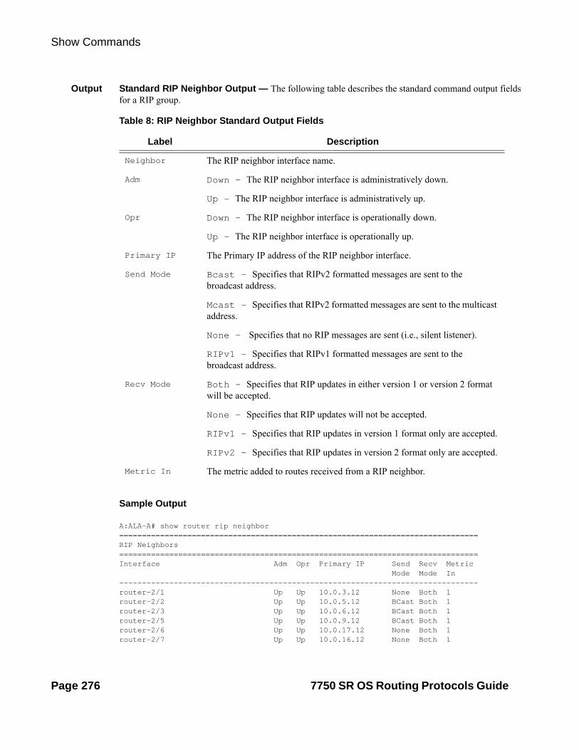
Show Commands
Output Standard RIP Neighbor Output — The following table describes the standard command output fields for a RIP group.
Table 8: RIP Neighbor Standard Output Fields
Label Description
Neighbor The RIP neighbor interface name.
Adm Down — The RIP neighbor interface is administratively down.
Up — The RIP neighbor interface is administratively up.
Opr Down — The RIP neighbor interface is operationally down.
Up — The RIP neighbor interface is operationally up.
Primary IP The Primary IP address of the RIP neighbor interface.
Send Mode Bcast — Specifies that RIPv2 formatted messages are sent to the broadcast address.
Mcast — Specifies that RIPv2 formatted messages are sent to the multicast address.
None — Specifies that no RIP messages are sent (i.e., silent listener).
RIPv1 — Specifies that RIPv1 formatted messages are sent to the broadcast address.
Recv Mode Both — Specifies that RIP updates in either version 1 or version 2 format will be accepted.
None — Specifies that RIP updates will not be accepted.
RIPv1 — Specifies that RIP updates in version 1 format only are accepted.
RIPv2 — Specifies that RIP updates in version 2 format only are accepted.
Metric In The metric added to routes received from a RIP neighbor.
Sample Output
A:ALA-A# show router rip neighbor===============================================================================RIP Neighbors===============================================================================Interface Adm Opr Primary IP Send Recv Metric Mode Mode In -------------------------------------------------------------------------------router-2/1 Up Up 10.0.3.12 None Both 1 router-2/2 Up Up 10.0.5.12 BCast Both 1 router-2/3 Up Up 10.0.6.12 BCast Both 1 router-2/5 Up Up 10.0.9.12 BCast Both 1 router-2/6 Up Up 10.0.17.12 None Both 1 router-2/7 Up Up 10.0.16.12 None Both 1
Page 276 7750 SR OS Routing Protocols Guide

RIP
===============================================================================A:ALA-A#
Output Detailed RIP Neighbor Output — The following table describes the standard command output fields for a RIP group.
Label Description
Neighbor The RIP neighbor name.
Description The RIP neighbor description. No Description Available indi-cates no description is configured.
Primary IP The RIP neighbor interface primary IP address.
Group The RIP group name of the neighbor interface.
Admin State Down — The RIP neighbor interface is administratively down.
Up — The RIP neighbor interface is administratively up.
Oper State Down — The RIP neighbor interface is operationally down.
Up — The RIP neighbor interface is operationally up.
Send Mode Bcast — Specifies that RIPv2 formatted messages are sent to the broadcast address.
Mcast — Specifies that RIPv2 formatted messages are sent to the multicast address.
None — Specifies that no RIP messages are sent (i.e., silent listener).
RIPv1 — Specifies that RIPv1 formatted messages are sent to the broadcast address.
Recv Mode Both — Specifies that RIP updates in either version 1 or version 2 format will be accepted.
None — Specifies that RIP updates will not be accepted.
RIPv1 — Specifies that RIP updates in version 1 format only will be accepted.
RIPv2 — Specifies that RIP updates in version 2 format only will be accepted.
Metric In The metric value added to routes received from a RIP neighbor.
Metric Out The value added to routes exported into RIP and advertised to RIP neighbors.
Split Horizon Disabled — Split horizon disabled for the neighbor.
Enabled — Split horizon and poison reverse enabled for the neigh-bor.
7750 SR OS Routing Protocols Guide Page 277

Show Commands
Sample Detailed Output
A:ALA-A# show router rip neighbor detail===============================================================================RIP Neighbors (Detail)===============================================================================-------------------------------------------------------------------------------Neighbor "router-2/7"-------------------------------------------------------------------------------Description : No Description AvailablePrimary IP : 10.0.16.12 Group : seven Admin State : Up Oper State : Up Send Mode : None Receive Mode : Both Metric In : 1 Metric Out : 1 Split Horizon : Enabled Check Zero : Disabled Message Size : 25 Preference : 100 Auth. Type : None Update Timer : 3 Timeout Timer : 6 Flush Timer : 6 Export Policies: Rip2Rip direct2Rip bgp2RipImport Policies: None===============================================================================A:ALA-A#
Check Zero Disabled — Checking of the mandatory zero fields in the RIPv1 and RIPv2 specifications are not checked allowing receipt of RIP mes-sages even if mandatory zero fields are non-zero for the neighbor.
Enabled — checking of the mandatory zero fields in the RIPv1 and RIPv2 specifications and rejecting non-compliant RIP messages is enabled for the neighbor.
Message Size The maximum number of routes per RIP update message.
Preference The preference of RIP routes from the neighbor.
Auth. Type Specifies the authentication type.
Update Timer The current setting of the RIP update timer value expressed in seconds.
Timeout Timer The current RIP timeout timer value expressed in seconds.
Export Policies The export route policy that is used to determine routes advertised to all peers.
Import Policies The import route policy that is used to determine which routes are accepted from RIP neighbors.
Label Description (Continued)
Page 278 7750 SR OS Routing Protocols Guide

RIP
Sample Output
A:ALA-A# show router rip neighbors interface advertised-routes ===============================================================================RIP Advertised Routes ===============================================================================Destination Interface NextHop Metric Tag TTL -------------------------------------------------------------------------------180.0.0.2/32 180.1.8.12 0.0.0.0 10 0x2002 n/a 180.0.0.5/32 180.1.8.12 0.0.0.0 10 0x2002 n/a 180.0.0.8/32 180.1.8.12 0.0.0.0 10 0x2002 n/a 180.0.0.9/32 180.1.8.12 0.0.0.0 10 0x2002 n/a 180.0.0.10/32 180.1.8.12 0.0.0.0 10 0x2002 n/a 180.0.0.11/32 180.1.8.12 0.0.0.0 10 0x2002 n/a 180.0.0.12/32 180.1.8.12 0.0.0.0 1 0x0000 n/a 180.0.0.13/32 180.1.8.12 0.0.0.0 10 0x2002 n/a 180.0.0.14/32 180.1.8.12 0.0.0.0 16 0x0000 n/a 180.0.0.15/32 180.1.8.12 0.0.0.0 2 0x0000 n/a 180.0.0.16/32 180.1.8.12 0.0.0.0 3 0x0000 n/a -------------------------------------------------------------------------------No. of Advertised Routes: 11===============================================================================A:ALA-A#
peer
Syntax peer [ip-int-name]
Context show>router>rip
Description Displays RIP peer information.
Parameters ip-int-name — Dispays peer information for peers on the specified IP interface.
Default display peers for all interfaces
Output RIP Peer Output — The following table describes the command output fields for a RIP peer.
Label Description
Peer IP Addr The IP address of the peer router.
Interface Name The peer interface name.
Version The version of RIP running on the peer.
Last Update The number of days since the last update.
No. of Peers The number of RIP peers.
Sample Output
A:ALA-A# show router rip peers===============================================================================
7750 SR OS Routing Protocols Guide Page 279

Show Commands
RIP Peers===============================================================================Peer IP Addr Interface Name Version Last Update -------------------------------------------------------------------------------10.0.5.13 router-2/2 RIPv2 0 10.0.6.16 router-2/3 RIPv2 2 10.0.9.14 router-2/5 RIPv2 8 10.0.10.15 router-2/4 RIPv2 0 -------------------------------------------------------------------------------No. of Peers: 4===============================================================================A:ALA-A#
statistics
Syntax statistics [ip-addr | ip-int-name]
Context show>router>rip
Description Display interface level statistics for the RIP protocol
If no IP address or interface name is specified, then all configured RIP interfaces are displayed.
If an IP address or interface name is specified, then only data regarding the specified RIP interface is displayed.
Parameters ip-addr | ip-int-name — Displays statistics for the specified IP interface.
Output RIP Statistics Output — The following table describes the output fields for RIP statistics.
Label Description
Learned Routes The number of RIP-learned routes were exported to RIP neighbors.
Timed Out Routes The number of routes that have been timed out.
Current Memory The amount of memory used by this RIP router instance.
Maximum Memory The amount of memory allocated for this RIP router instance.
Interface Displays the name of each interface configured in RIP and associated RIP statistics.
Primary IP The interface IP address.
Update Timer The current setting of the RIP update timer value expressed in seconds.
Timeout Timer The current RIP timeout timer value expressed in seconds.
Flush Timer The number of seconds after a route has been declared invalid that it is flushed from the route database.
Updates Sent Total — The total number of RIP updates that were sent.
Last 5 Min — The number of RIP updates that were sent in the last 5 minutes.
Page 280 7750 SR OS Routing Protocols Guide

RIP
Last 1 Min — The number of RIP updates that were sent in the last 1 minute.
Triggered Updates Total — The total number of triggered updates sent. These updates are sent before the entire RIP routing table is sent.
Last 5 Min — The number of triggered updates that were sent in the last 5 minutes.
Last 1 Min — The number of triggered updates that were sent in the last 1 minute.
Bad Packets Received
Total — The total number of RIP updates received on this interface that were discarded as invalid.
Last 5 Min — The number of RIP updates received on this inter-face that were discarded as invalid in the last 5 minutes.
Last 1 Min — The number of RIP updates received on this inter-face that were discarded as invalid in the last 1 minute.
RIPv1 Updates Received
Total — The total number of RIPv1 updates received.
Last 5 Min — The number of RIPv1 updates received in the last 5 minutes.
Last 1 Min — The number of RIPv1 updates received in the last 1 minute.
RIPv1 Updates Ignored
Total — The total number of RIPv1 updates ignored.
Last 5 Min — The number of RIPv1 updates ignored in the last 5 minutes.
Last 1 Min — The number of RIPv1 updates ignored in the last 1 minute.
RIPv1 Bad Routes Total — The total number of bad routes received from the peer.
Last 5 Min — The number of bad routes received from the peer in the last 5 minutes.
Last 1 Min — The number of bad routes received from the peer in the last minute.
RIPv1 Requests Received
Total — The total number of times the router received RIPv1 route requests from other routers.
Last 5 Min — The number of times the router received RIPv1 route requests from other routers in the last 5 minutes.
Label Description (Continued)
7750 SR OS Routing Protocols Guide Page 281

Show Commands
Last 1 Min — The number of times the router received RIPv1 route requests from other routers in the last 1 minute.
RIPv1 Requests Ignored
Total — The total number of times the router ignored RIPv1 route requests from other routers.
Last 5 Min — The number of times the router ignored RIPv1 route requests from other routers in the last 5 minutes.
Last 1 Min — The number of times the router ignored RIPv1 route requests from other routers in the last 1 minute.
RIPv2 Updates Received
Total — The total number of RIPv2 updates received.
Last 5 Min — The number of RIPv2 updates received in the last 5 minutes.
Last 1 Min — The number of RIPv2 updates received in the last minute.
RIPv2 Updates Ignored
Total — The total number of RIPv2 updates ignored.
Last 5 Min — The number of RIPv2 updates ignored in the last 5 minutes.
Last 1 Min — The number of RIPv2 updates ignored in the last minute.
RIPv2 Bad Routes Total — The total number of RIPv2 bad routes received from the peer.
Last 5 Min — The number of RIPv2 bad routes received from the peer in the last 5 minutes.
Last 1 Min — The number of RIPv2 bad routes received from the peer in the last minute.
RIPv2 Requests Received
Total — The total number of times the router received RIPv2 route requests from other routers.
Last 5 Min — The number of times the router received RIPv2 route requests from other routers in the last 5 minutes.
Last 1 Min — The number of times the router received RIPv2 route requests from other routers in the last minute.
RIPv2 Requests Ignored
Total — The total number of times the router ignored RIPv2 route requests from other routers.
Last 5 Min — The number of times the router ignored RIPv2 route requests from other routers in the last 5 minutes.
Label Description (Continued)
Page 282 7750 SR OS Routing Protocols Guide

RIP
Sample Output
A:ALA-A# show router rip statistics ===============================================================================RIP Statistics ===============================================================================Learned Routes : 0 Timed Out Routes : 0 Current Memory : 120624 Maximum Memory : 262144 -------------------------------------------------------------------------------Interface "to-web" -------------------------------------------------------------------------------Primary IP : 10.1.1.3 Update Timer : 30 Timeout Timer : 180 Flush Timer : 120 Counter Total Last 5 Min Last 1 Min -------------------------------------------------------------------------------Updates Sent 0 0 0 Triggered Updates 0 0 0 Bad Packets Received 0 0 0 RIPv1 Updates Received 0 0 0 RIPv1 Updates Ignored 0 0 0 RIPv1 Bad Routes 0 0 0 RIPv1 Requests Received 0 0 0 RIPv1 Requests Ignored 0 0 0 RIPv2 Updates Received 0 0 0 RIPv2 Updates Ignored 0 0 0 RIPv2 Bad Routes 0 0 0 RIPv2 Requests Received 0 0 0 RIPv2 Requests Ignored 0 0 0 Authentication Errors 0 0 0 ===============================================================================A:ALA-A#
Last 1 Min — The number of times the router ignored RIPv2 route requests from other routers in the last minute.
Authentication Errors
Total — The total number of authentication errors to secure table updates.
Last 5 Min — The number of authentication errors to secure table updates in the last 5 minutes.
Last 1 Min — The number of authentication errors to secure table updates in the last minute.
Label Description (Continued)
7750 SR OS Routing Protocols Guide Page 283

Clear Commands
Clear Commands
database
Syntax database
Context clear>router>rip
Description Flush all routes in the RIP database.
statistics
Syntax statistics [neighbor ip-int-name | ip-address]
Context clear>router>rip
Description Clears statistics for RIP neighbors.
Parameters neighbor ip-int-name | ip-address — Clears the statistics for the specified RIP interface.
Default clears statistics for all RIP interfaces
Page 284 7750 SR OS Routing Protocols Guide

RIP
Debug RIP Commands
auth
Syntax [no] auth [neighbor ip-int-name | ip-addr]
Context debug>router>rip
Description This command enables debugging for RIP authentication.
Parameters neighbor ip-addr | ip-int-name — Debugs the RIP authentication for the neighbor IP address or interface.
error
Syntax [no] error [neighbor ip-int-name | ip-addr]
Context debug>router>rip
Description This command enables debugging for RIP errors.
Parameters neighbor ip-addr | ip-int-name — Debugs the RIP errors sent on the neighbor IP address or interface.
events
Syntax [no] events [neighbor ip-int-name | ip-addr]
Context debug>router>rip
Description This command enables debugging for RIP events.
Parameters neighbor ip-addr | ip-int-name — Debugs the RIP events sent on the neighbor IP address or interface.
holddown
Syntax [no] holddown [neighbor ip-int-name | ip-addr]
Context debug>router>rip
Description This command enables debugging for RIP holddowns.
Parameters neighbor ip-addr | ip-int-name — Debugs the RIP holddowns sent on the neighbor IP address or interface.
7750 SR OS Routing Protocols Guide Page 285

Debug RIP Commands
packets
Syntax [no] packets [neighbor ip-int-name | ip-addr]
Context debug>router>rip
Description This command enables debugging for RIP packets.
Parameters neighbor ip-addr | ip-int-name — Debugs the RIP packets sent on the neighbor IP address or interface.
request
Syntax [no] request [neighbor ip-int-name | ip-addr]
Context debug>router>rip
Description This command enables debugging for RIP requests.
Parameters neighbor ip-addr | ip-int-name — Debugs the RIP requests sent on the neighbor IP address or interface.
trigger
Syntax [no] trigger [neighbor ip-int-name | ip-addr]
Context debug>router>rip
Description This command enables debugging for RIP trigger updates.
Parameters neighbor ip-addr | ip-int-name — Debugs the RIP updates sent on the neighbor IP address or interface.
updates
Syntax [no] updates [neighbor ip-int-name | ip-addr]
Context debug>router>rip
Description This command enables debugging for RIP updates.
Parameters neighbor ip-addr | ip-int-name — Debugs the RIP updates sent on the neighbor IP address or interface.
Page 286 7750 SR OS Routing Protocols Guide

OSPF
In This Chapter
This chapter provides information about configuring the Open Shortest Path First (OSPF) protocol.
Topics in this chapter include:
• Configuring OSPF on page 288
OSPF Areas on page 289
Backbone Area on page 289
Stub Area on page 290
Not-So-Stubby Area on page 291
OSPF Super Backbone on page 292
Authentication on page 303
OSPFv3 Graceful Restart Helper on page 298
Virtual Links on page 300
Neighbors and Adjacencies on page 301
Link-State Advertisements on page 302
Metrics on page 302
Authentication on page 303
IP Subnets on page 304
Preconfiguration Recommendations on page 304
• OSPF Configuration Process Overview on page 313
• Configuration Notes on page 314
7750 SR OS Routing Protocols Guide Page 287
Configuring OSPF
Configuring OSPF
OSPF (Open Shortest Path First) is a hierarchical link state protocol. OSPF is an interior gateway protocol (IGP) used within large autonomous systems (ASs). OSPF routers exchange state, cost, and other relevant interface information with neighbors. The information exchange enables all participating routers to establish a network topology map. Each router applies the Dijkstra algorithm to calculate the shortest path to each destination in the network. The resulting OSPF forwarding table is submitted to the routing table manager to calculate the routing table.
When a router is started with OSPF configured, OSPF, along with the routing-protocol data structures, is initialized and waits for indications from lower-layer protocols that its interfaces are functional. Alcatel-Lucent’s implementation of OSPF conforms to OSPF Version 2 specifications presented in RFC 2328, OSPF Version 2 and OSPF Version 3 specifications presented in RFC 2740, OSPF for IPv6. Routers running OSPF can be enabled with minimal configuration. All default and command parameters can be modified.
Changes between OSPF for IPv4 and OSPF3 for IPv6 include the following:
• Addressing semantics have been removed from OSPF packets and the basic link-state advertisements (LSAs). New LSAs have been created to carry IPv6 addresses and prefixes.
• OSPF3 runs on a per-link basis, instead of on a per-IP-subnet basis.
• Flooding scope for LSAs has been generalized.
• Unlike OSPFv2, OSPFv3 authentication relies on IPV6's authentication header and encapsulating security payload.
• Most packets in OSPF for IPv6 are almost as compact as those in OSPF for IPv4, even with the larger IPv6 addresses.
• Most field and packet-size limitations present in OSPF for IPv4 have been relaxed.
• Option handling has been made more flexible.
Key OSPF features are:
• Backbone areas
• Stub areas
• Not-So-Stubby areas (NSSAs)
• Virtual links
• Authentication
• Route redistribution
• Routing interface parameters
• OSPF-TE extensions (Alcatel-Lucent’s implementation allows MPLS fast reroute)
Page 288 7750 SR OS Routing Protocols Guide

OSPF
OSPF Areas
The hierarchical design of OSPF allows a collection of networks to be grouped into a logical area. An area’s topology is concealed from the rest of the AS which significantly reduces OSPF protocol traffic. With the proper network design and area route aggregation, the size of the route-table can be drastically reduced which results in decreased OSPF route calculation time and topological database size.
Routing in the AS takes place on two levels, depending on whether the source and destination of a packet reside in the same area (intra-area routing) or different areas (inter-area routing). In intra-area routing, the packet is routed solely on information obtained within the area; no routing information obtained from outside the area is used.
Routers that belong to more than one area are called area border routers (ABRs). An ABR maintains a separate topological database for each area it is connected to. Every router that belongs to the same area has an identical topological database for that area.
Backbone Area
The OSPF backbone area, area 0.0.0.0, must be contiguous and all other areas must be connected to the backbone area. The backbone distributes routing information between areas. If it is not practical to connect an area to the backbone (see area 0.0.0.5 in Figure 7) then the ABRs (such as routers Y and Z) must be connected via a virtual link. The two ABRs form a point-to-point-like adjacency across the transit area (see area 0.0.0.4).
7750 SR OS Routing Protocols Guide Page 289

Configuring OSPF
Figure 7: Backbone Area
Area 0.0.0.1
Area 0.0.0.3
RIP Domain
Area 0.0.0.2
Area 0.0.0.4
Area 0.0.0.5
OSRG035
Area 0.0.0.0
OSPF Domain
Y
Z
Stub Area
A stub area is a designated area that does not allow external route advertisements. Routers in a stub area do not maintain external routes. A single default route to an ABR replaces all external routes. This OSPF implementation supports the optional summary route (type-3) advertisement suppression from other areas into a stub area. This feature further reduces topological database sizes and OSPF protocol traffic, memory usage, and CPU route calculation time.
In Figure 7, areas 0.0.0.1, 0.0.0.2 and 0.0.0.5 could be configured as stub areas. A stub area cannot be designated as the transit area of a virtual link and a stub area cannot contain an AS boundary router. An AS boundary router exchanges routing information with routers in other ASs.
Page 290 7750 SR OS Routing Protocols Guide

OSPF
Not-So-Stubby Area
Another OSPF area type is called a Not-So-Stubby area (NSSA). NSSAs are similar to stub areas in that no external routes are imported into the area from other OSPF areas. External routes learned by OSPF routers in the NSSA area are advertised as type-7 LSAs within the NSSA area and are translated by ABRs into type-5 external route advertisements for distribution into other areas of the OSPF domain. An NSSA area cannot be designated as the transit area of a virtual link.
In Figure 7, area 0.0.0.3 could be configured as a NSSA area.
7750 SR OS Routing Protocols Guide Page 291

Configuring OSPF
OSPF Super Backbone
The 77x0 PE routers have implemented a version of the BGP/OSPF interaction procedures as defined in RFC 4577, OSPF as the Provider/Customer Edge Protocol for BGP/MPLS IP Virtual Private Networks (VPNs). Features included in this RFC includes:
• Loop prevention
• Handling LSAs received from the CE
• Sham links
• Managing VPN-IPv4 routes received by BGP
VPRN routes can be distributed among the PE routers by BGP. If the PE uses OSPF to distribute routes to the CE router, the standard procedures governing BGP/OSPF interactions causes routes from one site to be delivered to another in type 5 LSAs, as AS-external routes.
The MPLS VPN super backbone behaves like an additional layer of hierarchy in OSPF. The PE-routers that connect the respective OSPF areas to the super backbone function as OSPF Area Border Routers (ABR) in the OSPF areas to which they are attached. In order to achieve full compatibility, they can also behave as AS Boundary Routers (ASBR) in non-stub areas.
The PE-routers insert inter-area routes from other areas into the area in which the CE-router is present. The CE-routers are not involved at any level nor are they aware of the super backbone or of other OSPF areas present beyond the MPLS VPN super backbone.
The CE always assumes the PE is an ABR:
• If the CE is in the backbone then the CE router assumes that the PE is an ABR linking one or more areas to the backbone.
• If the CE in not in the backbone then the CE believes that the backbone is on the other side of the PE.
• As such the super backbone looks like another area to the CE.
Page 292 7750 SR OS Routing Protocols Guide
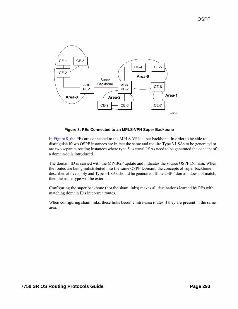
OSPF
Figure 8: PEs Connected to an MPLS-VPN Super Backbone
In Figure 8, the PEs are connected to the MPLS-VPN super backbone. In order to be able to distinguish if two OSPF instances are in fact the same and require Type 3 LSAs to be generated or are two separate routing instances where type 5 external LSAs need to be generated the concept of a domain-id is introduced.
The domain ID is carried with the MP-BGP update and indicates the source OSPF Domain. When the routes are being redistributed into the same OSPF Domain, the concepts of super backbone described above apply and Type 3 LSAs should be generated. If the OSPF domain does not match, then the route type will be external.
Configuring the super backbone (not the sham links) makes all destinations learned by PEs with matching domain IDs inter-area routes.
When configuring sham links, these links become intra-area routes if they are present in the same area.
OSSG185
CE-1
CE-2
CE-3
CE-6
CE-7CE-8CE-9
CE-4 CE-5
ABRPE-1
ABRPE-2
SuperBackbone
Area-0
Area-0
Area-1Area-2
7750 SR OS Routing Protocols Guide Page 293

Configuring OSPF
Figure 9: Sham Links
Figure 9 displays the red link between CE-3 and CE-4 could be a low speed OC-3/STM-1 link but because it establishes a intra-area route connection between the CE-3 and CE-4 the potentially high-speed PE-1 to PE-2 connection will not be utilized. Even with a super backbone configuration it is regarded as a inter-area connection.
The establishment of the (green) sham-link is also constructed as an intra-area link between PE routers, a normal OSPF adjacency is formed and the link-state database is exchanged across the MPLS-VPRN. As a result, the desired intra-area connectivity is created, at this time the cost of the green and red links can be managed such that the red link becomes a standby link only in case the VPN fails.
As the shamlink forms an adjacency over the MPLS-VPRN backbone network, be aware that when protocol-protection is enabled in the config>sys>security>cpu-protection>protocol-protection context, the operator must explicit allow the OSPF packets to be received over the backbone network. This performed using the allow-sham-links parameter of the protocol-protection command.
Sham Links
OSSG186
CE-1
CE-2
CE-3
CE-6
CE-7CE-8CE-9
CE-4 CE-5
ABRPE-1
ABRPE-2
Area-0
Area-0
Area-1Area-2
Page 294 7750 SR OS Routing Protocols Guide
OSPF
Implementing the OSPF Super Backbone
With the OSPF super backbone architecture, the continuity of OSPF routing is preserved:
• The OSPF intra-area LSAs (type-1 and type-2) advertised bye the CE are inserted into the MPLS-VPRN super backbone by redistributing the OSPF route into MP-BGP by the PE adjacent to the CE.
• The MP-BGP route is propagated to other PE-routers and inserted as an OSPF route into other OSPF areas. Considering the PEs across the super backbone always act as ABRs they will generate inter area route OSPF summary LSAs, Type 3.
• The inter-area route can now be propagated into other OSPF areas by other customer owned ABRs within the customer site.
• Customer Area 0 (backbone) routes when carried across the MPLS-VPRN using MPBGP will appear as Type 3 LSAs even if the customer area remains area 0 (backbone).
A BGP extended community (OSPF domain ID) provides the source domain of the route. This domain ID is not carried by OSPF but carried by MP-BGP as an extended community attribute.
If the configured extended community value matches the receiving OSPF domain, then the OSPF super backbone is implemented.
From a BGP perspective, the cost is copied into the MED attribute.
Loop Avoidance
If a route sent from a PE router to a CE router could then be received by another PE router from one of its own CE routers then it is possible for routing loops to occur. RFC 4577 specifies several methods of loop avoidance.
DN-BIT
When a Type 3 LSA is sent from a PE router to a CE router, the DN bit in the LSA options field is set. This is used to ensure that if any CE router sends this Type 3 LSA to a PE router, the PE router will not redistribute it further.
When a PE router needs to distribute to a CE router a route that comes from a site outside the latter's OSPF domain, the PE router presents itself as an ASBR (Autonomous System Border Router), and distributes the route in a type 5 LSA. The DN bit MUST be set in these LSAs to ensure that they will be ignored by any other PE routers that receive them.
DN-BIT loop avoidance is also supported.
7750 SR OS Routing Protocols Guide Page 295

Configuring OSPF
Route Tag
If a particular VRF in a PE is associated with an instance of OSPF, then by default it is configured with a special OSPF route tag value called the VPN route tag. This route tag is included in the Type 5 LSAs that the PE originates and sends to any of the attached CEs. The configuration and inclusion of the VPN Route Tag is required for backward compatibility with deployed implementations that do not set the DN bit in Type 5 LSAs.
Sham Links
A sham link is only required if a backdoor link (shown as the red link in Figure 9) is present, otherwise configuring an OSPF super backbone will probably suffice.
Page 296 7750 SR OS Routing Protocols Guide

OSPF
OSPFv3 Authentication
OSPFv3 authentication requires IPv6 IPsec and supports the following:
• IPsec transport mode
• AH and ESP
• Manual keyed IPsec Security Association (SA)
• Authentication Algorithms MD5 and SHA1
To pass OSPFv3 authentication, OSPFv3 peers must have matching inbound and outbound SAs configured using the same SA parameters (SPI, keys, etc.). THe implementation must allow the use of one SA for both inbound and outbound directions.
This feature is supported on IES and VPRN interfaces as well as on virtual links.
The re-keying procedure defined in RFC 4552, Authentication/Confidentiality for OSPFv3, supports the following:
• For every router on the link, create an additional inbound SA for the interface being re-keyed using a new SPI and the new key.
• For every router on the link, replace the original outbound SA with one using the new SPI and key values. The SA replacement operation should be atomic with respect to sending OSPFv3 packet on the link so that no OSPFv3 packets are sent without authentication or encryption.
• For every router on the link, remove the original inbound SA.
The key rollover procedure automatically starts when the operator changes the configuration of the inbound static-sa or bi-directional static-sa under an interface or virtual link. Within the KeyRolloverInterval time period, OSPF3 accepts packets with both the previous inbound static-sa and the new inbound static-sa, and the previous outbound static-sa should continue to be used. When the timer expires, OSPF3 will only accept packets with the new inbound static-sa and for outgoing OSPF3 packets, the new outbound static-sa will be used instead.
7750 SR OS Routing Protocols Guide Page 297

Configuring OSPF
Figure 10: GRACE LSA Format
OSPFv3 Graceful Restart Helper
This feature extends the Graceful Restart helper function supported under other protocols to OSPFv3.
The primary difference between graceful restart helper for OSPFv2 and OSPFv3 is in OSPFv3 a different grace-LSA format is used.
As the 7750 SR, 7450 ESS or 7710 (7x50) platforms can support a fully non-stop routing model for control plane high availability the 7x50 has no need for graceful restart as defined by the IETF in various RFCs for each routing protocol. However, since the 7x50 does need to co-exist in multi-vendor networks and other routers do not always support a true non-stop routing model with stateful failover between routing control planes, there is a need to support a Graceful Restart Helper function.
Graceful restart helper mode allows the SROS based system to provide other routers which have requested it, a grace period, during which the 7750 SR, 7450 ESS or 7710 systems will continue to use routes authored by or transiting the router requesting the grace period. This is typically used when another router is rebooting the control plane but the forwarding plane is expected to continue to forward traffic based on the previously available FIB.
Figure 10 displays the Graceful OSPF restart (GRACE) LSA format. See section 2.2 of RFC 5187, OSPFv3 Graceful Restart.
0 1 2 3 0 1 2 3 4 5 6 7 8 9 0 1 2 3 4 5 6 7 8 9 0 1 2 3 4 5 6 7 8 9 0 1 +-+-+-+-+-+-+-+-+-+-+-+-+-+-+-+-+-+-+-+-+-+-+-+-+-+-+-+-+-+-+-+-+ | LS age |0|0|0| 11 | +-+-+-+-+-+-+-+-+-+-+-+-+-+-+-+-+-+-+-+-+-+-+-+-+-+-+-+-+-+-+-+-+ | Link State ID | +-+-+-+-+-+-+-+-+-+-+-+-+-+-+-+-+-+-+-+-+-+-+-+-+-+-+-+-+-+-+-+-+ | Advertising Router | +-+-+-+-+-+-+-+-+-+-+-+-+-+-+-+-+-+-+-+-+-+-+-+-+-+-+-+-+-+-+-+-+ | LS sequence number | +-+-+-+-+-+-+-+-+-+-+-+-+-+-+-+-+-+-+-+-+-+-+-+-+-+-+-+-+-+-+-+-+ | LS checksum | Length | +-+-+-+-+-+-+-+-+-+-+-+-+-+-+-+-+-+-+-+-+-+-+-+-+-+-+-+-+-+-+-+-+ | | +- TLVs -+ | ... |
Page 298 7750 SR OS Routing Protocols Guide

OSPF
The Link State ID of a grace-LSA in OSPFv3 is the Interface ID of the interface originating the LSA.
The format of each TLV is:
0 1 2 3 0 1 2 3 4 5 6 7 8 9 0 1 2 3 4 5 6 7 8 9 0 1 2 3 4 5 6 7 8 9 0 1 +-+-+-+-+-+-+-+-+-+-+-+-+-+-+-+-+-+-+-+-+-+-+-+-+-+-+-+-+-+-+-+-+ | Type | Length | +-+-+-+-+-+-+-+-+-+-+-+-+-+-+-+-+-+-+-+-+-+-+-+-+-+-+-+-+-+-+-+-+ | Value... | +-+-+-+-+-+-+-+-+-+-+-+-+-+-+-+-+-+-+-+-+-+-+-+-+-+-+-+-+-+-+-+-+
TLV Format
Grace-LSA TLVs are formatted according to section 2.3.2 of RFC 3630, Traffic Engineering (TE) Extensions to OSPF Version 2. The Grace-LSA TLVs are used to carry the Grace period (type 1) and the reason the router initiated the graceful restart process (type 2).
Other information in RFC 5187 is directed to routers that require the full graceful restart mechanism as they do not support a stateful transition from primary or backup control plane module (CPM).
7750 SR OS Routing Protocols Guide Page 299

Configuring OSPF
Virtual Links
The backbone area in an OSPF AS must be contiguous and all other areas must be connected to the backbone area. Sometimes, this is not possible. You can use virtual links to connect to the backbone through a non-backbone area.
Figure 7 depicts routers Y and Z as the start and end points of the virtual link while area 0.0.0.4 is the transit area. In order to configure virtual links, the router must be an ABR. Virtual links are identified by the router ID of the other endpoint, another ABR. These two endpoint routers must be attached to a common area, called the transit area. The area through which you configure the virtual link must have full routing information.
Transit areas pass traffic from an area adjacent to the backbone or to another area. The traffic does not originate in, nor is it destined for, the transit area. The transit area cannot be a stub area or a NSSA area.
Virtual links are part of the backbone, and behave as if they were unnumbered point-to-point networks between the two routers. A virtual link uses the intra-area routing of its transit area to forward packets. Virtual links are brought up and down through the building of the shortest-path trees for the transit area.
Page 300 7750 SR OS Routing Protocols Guide

OSPF
Neighbors and Adjacencies
A router uses the OSPF Hello protocol to discover neighbors. A neighbor is a router configured with an interface to a common network. The router sends hello packets to a multicast address and receives hello packets in return.
In broadcast networks, a designated router and a backup designated router are elected. The designated router is responsible for sending link-state advertisements (LSAs) describing the network, which reduces the amount of network traffic.
The routers attempt to form adjacencies. An adjacency is a relationship formed between a router and the designated or backup designated router. For point-to-point networks, no designated or backup designated router is elected. An adjacency must be formed with the neighbor.
To significantly improve adjacency forming and network convergence, a network should be configured as point-to-point if only two routers are connected, even if the network is a broadcast media such as Ethernet.
When the link-state databases of two neighbors are synchronized, the routers are considered to be fully adjacent. When adjacencies are established, pairs of adjacent routers synchronize their topological databases. Not every neighboring router forms an adjacency. Routing protocol updates are only sent to and received from adjacencies. Routers that do not become fully adjacent remain in the two-way neighbor state.
7750 SR OS Routing Protocols Guide Page 301

Configuring OSPF
Link-State Advertisements
Link-state advertisements (LSAs) describe the state of a router or network, including router interfaces and adjacency states. Each LSA is flooded throughout an area. The collection of LSAs from all routers and networks form the protocol's topological database.
The distribution of topology database updates take place along adjacencies. A router sends LSAs to advertise its state according to the configured interval and when the router's state changes. These packets include information about the router's adjacencies, which allows detection of non-operational routers.
When a router discovers a routing table change or detects a change in the network, link state information is advertised to other routers to maintain identical routing tables. Router adjacencies are reflected in the contents of its link state advertisements. The relationship between adjacencies and the link states allow the protocol to detect non-operating routers. Link state advertisements flood the area. The flooding mechanism ensures that all routers in an area have the same topological database. The database consists of the collection of LSAs received from each router belonging to the area.
OSPF sends only the part that has changed and only when a change has taken place. From the topological database, each router constructs a tree of shortest paths with itself as root. OSPF distributes routing information between routers belonging to a single AS.
Metrics
In OSPF, all interfaces have a cost value or routing metric used in the OSPF link-state calculation. A metric value is configured based on hop count, bandwidth, or other parameters, to compare different paths through an AS. OSPF uses cost values to determine the best path to a particular destination: the lower the cost value, the more likely the interface will be used to forward data traffic.
Costs are also associated with externally derived routing data, such as those routes learned from the Exterior Gateway Protocol (EGP), like BGP, and is passed transparently throughout the AS. This data is kept separate from the OSPF protocol's link state data. Each external route can be tagged by the advertising router, enabling the passing of additional information between routers on the boundaries of the AS.
Page 302 7750 SR OS Routing Protocols Guide

OSPF
Authentication
All OSPF protocol exchanges can be authenticated. This means that only trusted routers can participate in autonomous system routing. Alcatel-Lucent’s implementation of OSPF supports plain text and Message Digest 5 (MD5) authentication (also called simple password).
MD5 allows an authentication key to be configured per network. Routers in the same routing domain must be configured with the same key. When the MD5 hashing algorithm is used for authentication, MD5 is used to verify data integrity by creating a 128-bit message digest from the data input. It is unique to that data. Alcatel-Lucent’s implementation of MD5 allows the migration of an MD5 key by using a key ID for each unique key.
By default, authentication is not enabled on an interface.
7750 SR OS Routing Protocols Guide Page 303

Configuring OSPF
IP Subnets
OSPF enables the flexible configuration of IP subnets. Each distributed OSPF route has a destination and mask. A network mask is a 32-bit number that indicates the range of IP addresses residing on a single IP network/subnet. This specification displays network masks as hexadecimal numbers; for example, the network mask for a class C IP network is displayed as 0xffffff00. Such a mask is often displayed as 255.255.255.0.
Two different subnets with same IP network number have different masks, called variable length subnets. A packet is routed to the longest or most specific match. Host routes are considered to be subnets whose masks are all ones (0xffffffff).
Preconfiguration Recommendations
Prior to configuring OSPF, the router ID must be available. The router ID is a 32-bit number assigned to each router running OSPF. This number uniquely identifies the router within an AS. OSPF routers use the router IDs of the neighbor routers to establish adjacencies. Neighbor IDs are learned when Hello packets are received from the neighbor.
Before configuring OSPF parameters, ensure that the router ID is derived by one of the following methods:
• Define the value in the config>router router-id context.
• Define the system interface in the config>router>interface ip-int-name context (used if the router ID is not specified in the config>router router-id context).
A system interface must have an IP address with a 32-bit subnet mask. The system interface is used as the router identifier by higher-level protocols such as OSPF and IS-IS. The system interface is assigned during the primary router configuration process when the interface is created in the logical IP interface context.
• If you do not specify a router ID, then the last four bytes of the MAC address are used.
NOTE: On the BGP protocol level, a BGP router ID can be defined in the config>router>bgp router-id context and is only used within BGP.
Page 304 7750 SR OS Routing Protocols Guide

OSPF
Multiple OSPF Instances
The main route table manager (RTM) can create multiple instances of OSPF by extending the current creation of an instance. A given interface can only be a member of a single OSPF instance.When an interface is configured in a given domain and needs to be moved to another domain the interface must first be removed from the old instance and re-created in the new instance.
Route Export Policies for OSPF
Route policies allow specification of the source OSPF process ID in the from and to parameters in the config>router>policy-options>policy-statement>entry>from context, for example from protocol ospf instance-id.
If an instance-id is specified, only routes installed by that instance are picked up for announcement. If no instance-id is specified, then only routes installed by the base instance is will be announced. The all keyword announces routes installed by all instances of OSPF.
When announcing internal (intra/inter-area) OSPF routes from another process, the default type should be type-1, and metric set to the route metric in RTM. For AS-external routes, by default the route type (type-1/2) should be preserved in the originated LSA, and metric set to the route metric in RTM. By default, the tag value should be preserved when an external OSPF route is announced by another process. All these can be changed with explicit action statements.
Export policy should allow a match criteria based on the OSPF route hierarchy, e.g. only intra-area, only inter-area, only external, only internal (intra/inter-area). There must also be a possibility to filter based on existing tag values.
7750 SR OS Routing Protocols Guide Page 305

Configuring OSPF
Preventing Route Redistribution Loops
The legacy method for this was to assign a tag value to each OSPF process and mark each external route originated within that domain with that value. However, since the tag value must be preserved throughout different OSPF domains, this only catches loops that go back to the originating domain and not where looping occurs in a remote set of domains. To prevent this type of loop, the route propagation information in the LSA must be accumulative. The following method has been implemented:
• The OSPF tag field in the AS-external LSAs is treated as a bit mask, rather than a scalar value. In other words, each bit in the tag value can be independently checked, set or reset as part of the routing policy.
• When a set of OSPF domains are provisioned in a network, each domain is assigned a specific bit value in the 32-bit tag mask. When an external route is originated by an ASBR using an internal OSPF route in a given domain, a corresponding bit is set in the AS-external LSA. As the route gets redistributed from one domain to another, more bits are set in the tag mask, each corresponding to the OSPF domain the route visited. Route redistribution looping is prevented by checking the corresponding bit as part of the export policy--if the bit corresponding to the announcing OSPF process is already set, the route is not exported there.
From the CLI perspective, this involves adding a set of from tag and action tag commands that allow for bit operations.
Page 306 7750 SR OS Routing Protocols Guide

OSPF
IP Fast-reroute (IP FRR) For OSPF and IS-IS Prefixes
This feature provides for the use of the Loop-Free Alternate (LFA) backup next-hop for forwarding in-transit and CPM generated IP packets when the primary next-hop is not available. . This means that a node resumes forwarding IP packets to a destination prefix without waiting for the routing convergence.
When any of the following events occurs, IGP instructs in the fast path the IOMs to enable the LFA backup next-hop:
• OSPF/IS-IS interface goes operationally down: physical or local admin shutdown.
• Timeout of a BFD session to a next-hop when BFD is enabled on the OSPF/IS-IS interface
IP FRR is supported on IPv4 OSPF/IS-IS prefixes forwarded in the base router instance to a network IP interface or to an IES SAP interface or spoke interface. It is also supported for VPRN VPN-IPv4 OSPF prefixes forwarded to a VPRN SAP interface or spoke interface. IP FRR also provides a LFA backup next-hop for the destination prefix of a GRE tunnel used in an SDP or in VPRN auto-bind.
The LFA next-hop pre-computation by IGP is described in RFC 5286 – “Basic Specification for IP Fast Reroute: Loop-Free Alternates”.
Refer to IP Fast-reroute (IP FRR) For IS-IS Prefixes on page 453 for IP FRR for OSPF prefixes.
IP FRR Configuration
The user first enables Loop-Free Alternate (LFA) computation by SPF under the IS-IS routing protocol level or under the OSPF routing protocol instance level:
config>router>isis>loopfree-alternateconfig>router>ospf>loopfree-alternateconfig>service>vprn>ospf>loopfree-alternate
The above commands instruct the IGP SPF to attempt to pre-compute both a primary next-hop and an LFA next-hop for every learned prefix. When found, the LFA next-hop is populated into the RTM along with the primary next-hop for the prefix.
Next the user enables IP FRR to cause RTM to download to IOM a LFA next-hop, when found by SPF, in addition to the primary next-hop for each prefix in the FIB.
config>router>ip-fast-reroute
7750 SR OS Routing Protocols Guide Page 307
Configuring OSPF
Reducing the Scope of the LFA Calculation by SPF
The user can instruct IGP to not include all interfaces participating in a specific IS-IS level or OSPF area in the SPF LFA computation. This provides a way of reducing the LFA SPF calculation where it is not needed.
config>router>isis>level>loopfree-alternate-exclude
config>router>ospf>area>loopfree-alternate-exclude
The user can also exclude a specific IP interface from being included in the LFA SPF computation by IS-IS or OSPF:
config>router>isis>interface> loopfree-alternate-exclude
config>router>ospf>area>interface> loopfree-alternate-exclude
Note that when an interface is excluded from the LFA SPF in IS-IS, it is excluded in both level 1 and level 2. When the user excludes an interface from the LFA SPF in OSPF, it is excluded in all areas. However, the above OSPF command can only be executed under the area in which the specified interface is primary and once enabled, the interface is excluded in that area and in all other areas where the interface is secondary. If the user attempts to apply it to an area where the interface is secondary, the command will fail.
Finally, the user can apply the same above commands for an OSPF instance within a VPRN service:
config>service>vprn>ospf>area>loopfree-alternate-exclude
config>service>vprn>ospf>area>interface>loopfree-alternate-exclude
ECMP Considerations
Whenever the SPF computation determined there is more than one primary next-hop for a prefix, it will not program any LFA next-hop in RTM. Thus, IP prefixes will resolve to the multiple primary next-hops in this case which provides the required protection.
IP FRR and RSVP Shortcut (IGP Shortcut)
IGP shortcuts are not supported in the LFA next-hop calculation.
Page 308 7750 SR OS Routing Protocols Guide

OSPF
Figure 11: Example Topology with Primary and LFA Routes
The primary route is via R3. The LFA route via R2 has two equal cost paths to reach R5. The path via R3 protects against failure of link R1-R3. This route is computed by R1 by checking that the cost for R2 to reach R5 via R3 is lower than the cost via routes R1 and R3. This condition is referred to as the “loop-free criterion”.
The path via R2 and R4 can be used to protect against the failure of router R3. However, with the link R2-R3 metric set to 5, R2 sees the same cost to forward a packet to R5 via R3 and R4. Thus R1 cannot guarantee that enabling the LFA next-hop R2 will protect against R3 node failure. This
OSPF and IS-IS Support for Loop-Free Alternate Calculation
SPF computation in IS-IS and OSPF is enhanced to compute LFA alternate routes for each learned prefix and populate it in RTM.
Figure 11 illustrates a simple network topology with point-to-point (P2P) interfaces and highlights three routes to reach router R5 from router R1.
R1 R2
R3 R4
R5
5
5
5
5 (8)
5
5
Primary Route
LFA Link-Protect Route
LFA Node-Protect Route
7750 SR OS Routing Protocols Guide Page 309
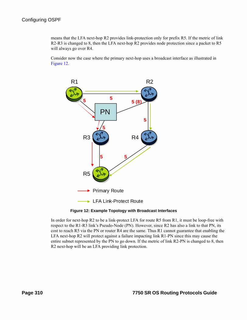
Configuring OSPF
Figure 12: Example Topology with Broadcast Interfaces
In order for next-hop R2 to be a link-protect LFA for route R5 from R1, it must be loop-free with respect to the R1-R3 link’s Pseudo-Node (PN). However, since R2 has also a link to that PN, its cost to reach R5 via the PN or router R4 are the same. Thus R1 cannot guarantee that enabling the LFA next-hop R2 will protect against a failure impacting link R1-PN since this may cause the entire subnet represented by the PN to go down. If the metric of link R2-PN is changed to 8, then R2 next-hop will be an LFA providing link protection.
means that the LFA next-hop R2 provides link-protection only for prefix R5. If the metric of link R2-R3 is changed to 8, then the LFA next-hop R2 provides node protection since a packet to R5 will always go over R4.
Consider now the case where the primary next-hop uses a broadcast interface as illustrated in Figure 12.
R1 R2
R3 R4
R5
5
5
55 (8)
5
5
Primary Route
LFA Link-Protect Route
PN
5
Page 310 7750 SR OS Routing Protocols Guide

OSPF
The following are the detailed equations for this criterion as provided in RFC 5286, Basic Specification for IP Fast Reroute: Loop-Free Alternates:
• Link-protect backup next-hop (primary next-hop R1-R3 is a P2P interface):
Distance_opt(R2, R5) < Distance_opt(R2, R1) + Distance_opt(R1, R5)
• Node-protect backup next-hop (primary next-hop R1-R3 is a P2P interface):
Distance_opt(R2, R5) < Distance_opt(R2, R3) + Distance_opt(R3, R5)
• Link-protect backup next-hop (primary next-hop R1-R3 is a broadcast interface):
Distance_opt(R2, R5) < Distance_opt(R2, PN) + Distance_opt(PN, R5)
Where PN stands for the R1-R3 link’s Pseudo-Node.
For the case of P2P interface, if SPF finds multiple LFA next-hops for a given primary next-hop, it follows the following selection algorithm:
A) It will pick the node-protect type in favor of the link-protect type.
B) If there is more than one LFA next-hop within the selected type, then it will pick one based on the least cost.
C) If more than one LFA next-hop with the same cost results from step (b), then SPF will select the first one. This is not a deterministic selection and will vary following each SPF calculation.
For the case of a broadcast interface, a node-protect LFA is not necessarily a link protect LFA if the path to the LFA next-hop goes over the same PN as the primary next-hop. Similarly, a link protect LFA may not guarantee link protection if it goes over the same PN as the primary next-hop. The selection algorithm when SPF finds multiple LFA next-hops for a given primary next-hop is modified as follows:
A) The algorithm splits the LFA next-hops into two sets:
The first set consists of LFA next-hops which do not go over the PN used by primary next-hop,
The second set consists of LFA next-hops which go over the PN used by the primary next-hop.
B) If there is more than one LFA next-hop in the first set, it will pick the node-protect type in favor of the link-protect type.
C) If there is more than one LFA next-hop within the selected type, then it will pick one based on the least cost.
D) If more than one LFA next-hop with equal cost results from step (c), SPF will select the first one from the remaining set. This is not a deterministic selection and will vary following each SPF calculation.
7750 SR OS Routing Protocols Guide Page 311

Configuring OSPF
E) If no LFA next-hop results from step (d), SPF will rerun steps (b-d) using the second set.
Note this algorithm is more flexible than strictly applying the link protect rule in the presence of a PN and specified in 5286. A node-protect LFA which does not avoid the PN, i.e., does not guarantee link protection, can still be selected as a last resort. The same thing, a link-protect LFA which does not avoid the PN may still be selected as a last resort.
Loop-Free Alternate Calculation for Inter-Area/inter-Level Prefixes
When SPF resolves OSPF inter-area prefixes or IS-IS inter-level prefixes, it will compute an LFA backup next-hop to the same exit area/border router as used by the primary next-hop.
Page 312 7750 SR OS Routing Protocols Guide

OSPF
Figure 13: OSPF Configuration and Implementation Flow
OSPF Configuration Process Overview
Figure 13 displays the process to provision basic OSPF parameters.
TURN UP
START
CONFIGURE THE ROUTER ID
DEFINE ONE OR MORE AREAS
DEFINE INTERFACES
DEFINE STUB AREA
DEFINE NSSA
CONFIGURE VIRTUAL LINKS
OPTIONAL
7750 SR OS Routing Protocols Guide Page 313

Configuration Notes
Configuration Notes
This section describes OSPF configuration caveats.
General
• Before OSPF can be configured, the router ID must be configured.
• The basic OSPF configuration includes at least one area and an associated interface.
• All default and command parameters can be modified.
OSPF Defaults
The following list summarizes the OSPF configuration defaults:
• By default, a router has no configured areas.
• An OSPF instance is created in the administratively enabled state.
Page 314 7750 SR OS Routing Protocols Guide

OSPF
Configuring OSPF with CLI
This section provides information to configure Open Shortest Path First (OSPF) using the command line interface.
Topics in this section include:
• OSPF Configuration Guidelines on page 316
• Basic OSPF Configuration on page 317
• Configuring the Router ID on page 318
• Configuring OSPF Components on page 319
Configuring the Router ID on page 318
Configuring an OSPF or OSPF3 Area on page 321
Configuring a Stub Area on page 322
Configuring a Not-So-Stubby Area on page 324
Configuring a Virtual Link on page 326
Configuring an Interface on page 328
Configuring Authentication on page 331
Assigning a Designated Router on page 334
Configuring Route Summaries on page 336
Configuring Route Preferences on page 338
• OSPF Configuration Management Tasks on page 341
Modifying a Router ID on page 341
Deleting a Router ID on page 343
Modifying OSPF Parameters on page 344
7750 SR OS Routing Protocols Guide Page 315

OSPF Configuration Guidelines
OSPF Configuration Guidelines
Configuration planning is essential to organize routers, backbone, non-backbone, stub, NSSA areas, and transit links. OSPF provides essential defaults for basic protocol operability. You can configure or modify commands and parameters. OSPF is not enabled by default.
The minimal OSPF parameters which should be configured to deploy OSPF are:
• Router ID
Each router running OSPF must be configured with a unique router ID. The router ID is used by both OSPF and BGP routing protocols in the routing table manager.
When configuring a new router ID, protocols will not automatically be restarted with the new router ID. Shut down and restart the protocol to initialize the new router ID.
• OSPF Instance
OSPF instances must be defined when configuring multiple instances and/or the instance being configured is not the base instance.
• An area
At least one OSPF area must be created. An interface must be assigned to each OSPF area.
• Interfaces
An interface is the connection between a router and one of its attached networks. An interface has state information associated with it, which is obtained from the underlying lower level protocols and the routing protocol itself. An interface to a network has associated with it a single IP address and mask (unless the network is an unnumbered point-to-point network). An interface is sometimes also referred to as a link.
Page 316 7750 SR OS Routing Protocols Guide

OSPF
Basic OSPF Configuration
This section provides information to configure OSPF and OSPF3 as well as configuration examples of common configuration tasks.
The minimal OSPF parameters that need to be configured are:
• A router ID - If a router-id is not configured in the config>router context, the router’s system interface IP address is used.
• One or more areas.
• Interfaces (interface "system").
Following is an example of a basic OSPF configuration:
ALA-A>config>router>ospf# info---------------------------------------------- area 0.0.0.0 interface "system" exit exit area 0.0.0.20 nssa exit interface "to-104" priority 10 exit exit area 0.0.1.1 exit----------------------------------------------ALA-A>config>router>ospf#A:ALA-48>config>router>ospf3# info---------------------------------------------- asbr overload timers lsa-arrival 50000 exit export "OSPF-Export" area 0.0.0.0 interface "system" exit exit area 0.0.0.20 nssa exit interface "SR1-2" exit exit area 0.0.0.25 stub default-metric 5000 exit exit
7750 SR OS Routing Protocols Guide Page 317

Basic OSPF Configuration
Configuring the Router ID
The router ID uniquely identifies the router within an AS. In OSPF, routing information is exchanged between autonomous systems, groups of networks that share routing information. It can be set to be the same as the loopback (system interface) address. Subscriber services also use this address as far-end router identifiers when service distribution paths (SDPs) are created. The router ID is used by both OSPF and BGP routing protocols. A router ID can be derived by:
• Defining the value in the config>router router-id context.
• Defining the system interface in the config>router>interface ip-int-name context (used if the router ID is not specified in the config>router router-id context).
• Inheriting the last four bytes of the MAC address.
• On the BGP protocol level. A BGP router ID can be defined in the config>router>bgp router-id context and is only used within BGP.
When configuring a new router ID, protocols are not automatically restarted with the new router ID. The next time a protocol is (re) initialized the new router ID is used. An interim period of time can occur when different protocols use different router IDs. To force the new router ID, issue the shutdown and no shutdown commands for each protocol that uses the router ID or restart the entire router.
The following displays a router ID configuration example:
A:ALA-B>config>router# info#------------------------------------------# IP Configuration#------------------------------------------ interface "system" address 10.10.10.104/32 exit interface "to-103" address 10.0.0.104/24 port 1/1/1 exit autonomous-system 100 router-id 10.10.10.104...#------------------------------------------A:ALA-B>config>router#
Page 318 7750 SR OS Routing Protocols Guide

OSPF
Configuring OSPF Components
Use the CLI syntax displayed below for:
• Configuring OSPF Parameters on page 319
• Configuring OSPF3 Parameters on page 320
• Configuring a Stub Area on page 322
• Configuring a Not-So-Stubby Area on page 324
• Configuring a Virtual Link on page 326
• Configuring an Interface on page 328
• Configuring Authentication on page 331
• Assigning a Designated Router on page 334
• Configuring Route Summaries on page 336
Configuring OSPF Parameters
The following displays a basic OSPF configuration example:
A:ALA-49>config>router>ospf# info---------------------------------------------- asbr overload overload-on-boot timeout 60 traffic-engineering export "OSPF-Export" graceful-restart helper-disable exit----------------------------------------------A:ALA-49>config>router>ospf# ex
7750 SR OS Routing Protocols Guide Page 319
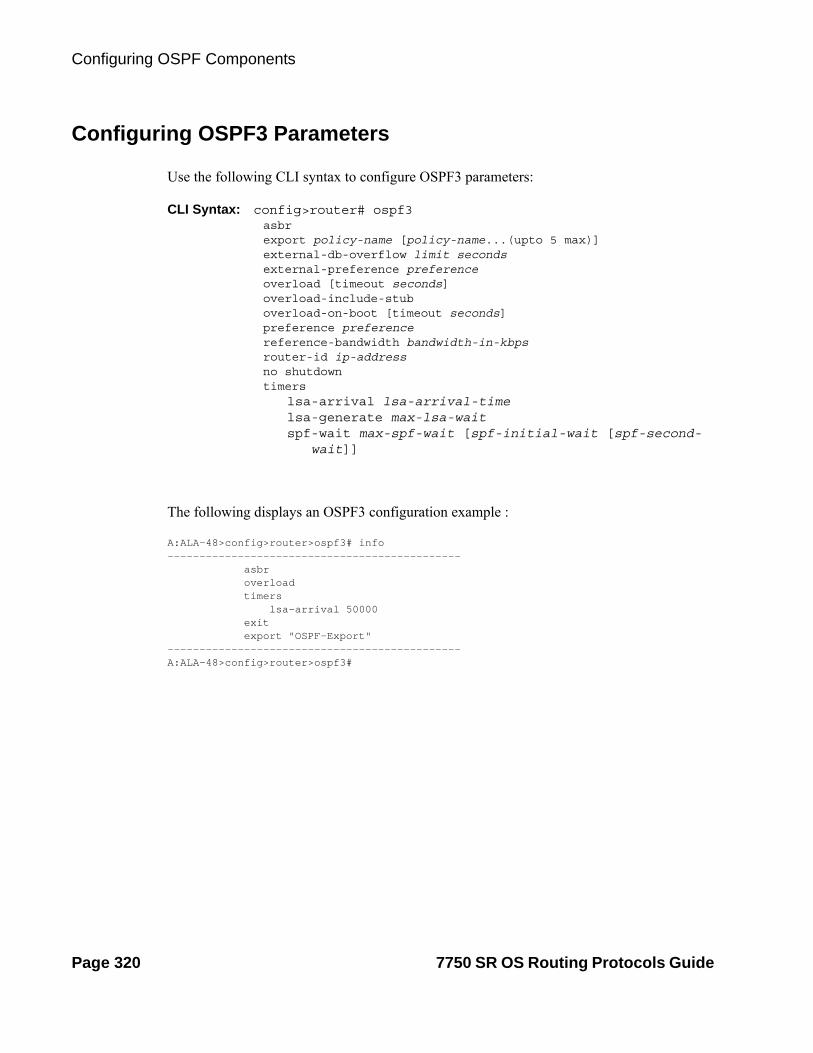
Configuring OSPF Components
Configuring OSPF3 Parameters
Use the following CLI syntax to configure OSPF3 parameters:
CLI Syntax: config>router# ospf3asbrexport policy-name [policy-name...(upto 5 max)]external-db-overflow limit secondsexternal-preference preferenceoverload [timeout seconds]overload-include-stuboverload-on-boot [timeout seconds]preference preferencereference-bandwidth bandwidth-in-kbpsrouter-id ip-addressno shutdowntimers
lsa-arrival lsa-arrival-timelsa-generate max-lsa-waitspf-wait max-spf-wait [spf-initial-wait [spf-second-
wait]]
The following displays an OSPF3 configuration example :
A:ALA-48>config>router>ospf3# info---------------------------------------------- asbr overload timers lsa-arrival 50000 exit export "OSPF-Export"----------------------------------------------A:ALA-48>config>router>ospf3#
Page 320 7750 SR OS Routing Protocols Guide

OSPF
Configuring an OSPF or OSPF3 Area
An OSPF area consists of routers configured with the same area ID. To include a router in a specific area, the common area ID must be assigned and an interface identified.
If your network consists of multiple areas you must also configure a backbone area (0.0.0.0) on at least one router. The backbone is comprised of the area border routers and other routers not included in other areas. The backbone distributes routing information between areas. The backbone is considered to be a participating area within the autonomous system. To maintain backbone connectivity, there must be at least one interface in the backbone area or have a virtual link configured to another router in the backbone area.
The minimal configuration must include an area ID and an interface. Modifying other command parameters are optional.
Use the following CLI syntax to configure an OSPF or OSPF3 area:
CLI Syntax: ospf ospf-instanceospf3
area area-idarea-range ip-prefix/mask [advertise|not-advertise]blackhole-aggregate
The following displays an OSPF area configuration example:
A:ALA-A>config>router>ospf# info---------------------------------------------- area 0.0.0.0 exit area 0.0.0.20 exit----------------------------------------------ALA-A>config>router>ospf#A:
7750 SR OS Routing Protocols Guide Page 321

Configuring OSPF Components
Configuring a Stub Area
Configure stub areas to control external advertisements flooding and to minimize the size of the topological databases on an area's routers. A stub area cannot also be configured as an NSSA.
By default, summary route advertisements are sent into stub areas. The no form of the summary command disables sending summary route advertisements and only the default route is advertised by the ABR. This example retains the default so the command is not entered.
If this area is configured as a transit area for a virtual link, then existing virtual links of a non-stub or NSSA area are removed when its designation is changed to NSSA or stub.
Stub areas for OSPF3 are configured the same as OSPF stub areas.
Use the following CLI syntax to configure virtual links:
CLI Syntax: ospfospf3area area-idstub
default-metric metricsummaries
The following displays a stub configuration example:
ALA-A>config>router>ospf>area># info----------------------------------------------... area 0.0.0.0 exit area 0.0.0.20 stub exit exit...----------------------------------------------ALA-A>config>router>ospf#
The following displays a stub configuration example:
ALA-A>config>router>ospf>area># info----------------------------------------------... area 0.0.0.0 exit area 0.0.0.20 stub exit exit...----------------------------------------------
Page 322 7750 SR OS Routing Protocols Guide

OSPF
ALA-A>config>router>ospf#
A:ALA-48>config>router>ospf3>area# info---------------------------------------------- stub default-metric 5000 exit----------------------------------------------A:ALA-48>config>router>ospf3>area#
7750 SR OS Routing Protocols Guide Page 323

Configuring OSPF Components
Configuring a Not-So-Stubby Area
You must explicitly configure an area to be a Not-So-Stubby Area (NSSA) area. NSSAs are similar to stub areas in that no external routes are imported into the area from other OSPF areas. The major difference between a stub area and an NSSA is an NSSA has the capability to flood external routes it learns throughout its area and by an area border router to the entire OSPF domain. An area cannot be both a stub area and an NSSA.
If this area is configured as a transit area for a virtual link, then existing virtual links of a non-stub or NSSA area are removed when its designation is changed to NSSA or stub.
Use the following CLI syntax to configure stub areas:
CLI Syntax: ospf ospf-instanceospf3area area-id
nssaarea-range ip-prefix/mask [advertise|not-advertise]originate-default-route [type-7]redistribute-externalsummaries
The following displays an NSSA configuration example:
A:ALA-49>config>router>ospf# info---------------------------------------------- asbr overload overload-on-boot timeout 60 traffic-engineering export "OSPF-Export" graceful-restart helper-disable exit area 0.0.0.0 exit area 0.0.0.20 stub exit exit area 0.0.0.25 nssa exit exit----------------------------------------------A:ALA-49>config>router>ospf#
Page 324 7750 SR OS Routing Protocols Guide

OSPF
The following displays a OSPF3 NSSA configuration example:
A:ALA-48>config>router>ospf3# info---------------------------------------------- asbr overload timers lsa-arrival 50000 exit export "OSPF-Export" area 0.0.0.0 exit area 0.0.0.20 stub exit exit area 0.0.0.25 nssa exit exit area 4.3.2.1 exit----------------------------------------------A:ALA-48>config>router>ospf3#
7750 SR OS Routing Protocols Guide Page 325

Configuring OSPF Components
Configuring a Virtual Link
The backbone area (area 0.0.0.0) must be contiguous and all other areas must be connected to the backbone area. If it is not practical to connect an area to the backbone then the area border routers must be connected via a virtual link. The two area border routers will form a point-to-point-like adjacency across the transit area. A virtual link can only be configured while in the area 0.0.0.0 context.
The router-id parameter specified in the virtual-link command must be associated with the virtual neighbor, that is, enter the virtual neighbor’s router ID, not the local router ID. The transit area cannot be a stub area or an NSSA. Use the following CLI syntax to configure stub areas:
CLI Syntax: ospf ospf-instancearea area-id
virtual-link router-id transit-area area-idauthentication-key [authentication-key|hash-key]
[hash] authentication-type [password|message-digest]
dead-interval secondshello-interval secondsmessage-digest-key key-id md5 [key|hash-key]
[hash|hash2]retransmit-interval secondstransit-delayno shutdown
The following displays a virtual link configuration example:
A:ALA-49>config>router>ospf# info---------------------------------------------- asbr overload overload-on-boot timeout 60 traffic-engineering export "OSPF-Export" graceful-restart helper-disable exit area 0.0.0.0 virtual-link 1.2.3.4 transit-area 1.2.3.4 hello-interval 9 dead-interval 40 exit exit area 0.0.0.20 stub exit exit area 0.0.0.25
Page 326 7750 SR OS Routing Protocols Guide
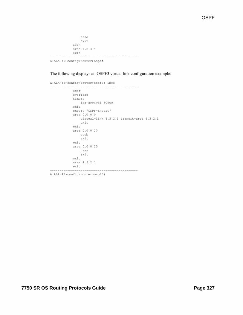
OSPF
nssa exit exit area 1.2.3.4 exit----------------------------------------------A:ALA-49>config>router>ospf#
The following displays an OSPF3 virtual link configuration example:
A:ALA-48>config>router>ospf3# info---------------------------------------------- asbr overload timers lsa-arrival 50000 exit export "OSPF-Export" area 0.0.0.0 virtual-link 4.3.2.1 transit-area 4.3.2.1 exit exit area 0.0.0.20 stub exit exit area 0.0.0.25 nssa exit exit area 4.3.2.1 exit----------------------------------------------A:ALA-48>config>router>ospf3#
7750 SR OS Routing Protocols Guide Page 327

Configuring OSPF Components
Configuring an Interface
In OSPF, an interface can be configured to act as a connection between a router and one of its attached networks. An interface includes state information that was obtained from underlying lower level protocols and from the routing protocol itself. An interface to a network is associated with a single IP address and mask (unless the network is an unnumbered point-to-point network). If the address is merely changed, then the OSPF configuration is preserved.
The passive command enables the passive property to and from the OSPF interface where passive interfaces are advertised as OSPF interfaces but do not run the OSPF protocol. By default, only interface addresses that are configured for OSPF are advertised as OSPF interfaces. The passive parameter allows an interface to be advertised as an OSPF interface without running the OSPF protocol. When enabled, the interface will ignore ingress OSPF protocol packets and not transmit any OSPF protocol packets.
An interface can be part of more than one area, as specified in RFC5185. To do this, add the keyword secondary when creating the interface.
Use the following CLI syntax to configure an OSPF interface:
CLI Syntax: ospf ospf-instancearea area-id
interface ip-int-nameadvertise-subnetauthentication-key [authentication-key|hash-key]
[hash|hash2]authentication-type [password|message-digest]bfd-enabledead-interval secondshello-interval secondsinterface-type {broadcast|point-to-point}message-digest-key key-id md5 [key|hash-
key][hash|hash2]metric metricmtu bytespassivepriority numberretransmit-interval secondsno shutdowntransit-delay seconds
The following displays an interface configuration example:
A:ALA-49>config>router>ospf# info---------------------------------------------- asbr overload overload-on-boot timeout 60
Page 328 7750 SR OS Routing Protocols Guide

OSPF
traffic-engineering export "OSPF-Export" graceful-restart helper-disable exit area 0.0.0.0 virtual-link 1.2.3.4 transit-area 1.2.3.4 hello-interval 9 dead-interval 40 exit interface "system" exit exit area 0.0.0.20 stub exit interface "to-103" exit exit area 0.0.0.25 nssa exit exit area 1.2.3.4 exit
area 4.3.2.1 interface "SR1-3" exit exit area 4.3.2.1 interface "SR1-3" secondary exit exit----------------------------------------------A:ALA-49>config>router>ospf# area 0.0.0.20
The following displays an interface configuration:
A:ALA-48>config>router>ospf3# info---------------------------------------------- asbr overload timers lsa-arrival 50000 exit export "OSPF-Export" area 0.0.0.0 virtual-link 4.3.2.1 transit-area 4.3.2.1 exit interface "system" exit exit area 0.0.0.20 stub exit interface "SR1-2" exit exit
7750 SR OS Routing Protocols Guide Page 329

Configuring OSPF Components
area 0.0.0.25 nssa exit exit area 4.3.2.1 exit
----------------------------------------------A:ALA-48>config>router>ospf3#
Page 330 7750 SR OS Routing Protocols Guide

OSPF
Configuring Authentication
Authentication must be explicitly configured. This feature is not available in the OSPF3 context. The following authentication commands can be configured on the interface level or the virtual link level:
• authentication-key — Configures the password used by the OSPF interface or virtual-link to send and receive OSPF protocol packets on the interface when simple password authentication is configured.
• authentication-type — Enables authentication and specifies the type of authentication to be used on the OSPF interface, either password or message digest.
• message-digest-key — Use this command when message-digest keyword is selected in the authentication-type command. The Message Digest 5 (MD5) hashing algorithm is used for authentication. MD5 is used to verify data integrity by creating a 128-bit message digest from the data input. It is unique to that specific data.
An special checksum is included in transmitted packets and are used by the far-end router to verify the packet by using an authentication key (a password). Routers on both ends must use the same MD5 key.
MD5 can be configured on each interface and each virtual link. If MD5 is enabled on an interface, then that interface accepts routing updates only if the MD5 authentication is accepted. Updates that are not authenticated are rejected. A router accepts only OSPF packets sent with the same key-id value defined for the interface.
When the hash parameter is not used, non-encrypted characters can be entered. Once configured using the message-digest-key command, then all keys specified in the command are stored in encrypted format in the configuration file using the hash keyword. When using the hash keyword the password must be entered in encrypted form. Hashing cannot be reversed. Issue the no message-digest-key key-id command and then re-enter the command without the hash parameter to configure an unhashed key.
The following CLI commands are displayed to illustrate the key authentication features. These command parameters can be defined at the same time interfaces and virtual-links are being configured. See Configuring an Interface on page 328 and Configuring a Virtual Link on page 326.
Use the following CLI syntax to configure authentication:
CLI Syntax: ospf ospf-instancearea area-id
interface ip-int-nameauthentication-key [authentication-key|hash-key]
[hash]authentication-type [password|message-digest]message-digest-key key-id md5 key [hash]
7750 SR OS Routing Protocols Guide Page 331

Configuring OSPF Components
virtual-link router-id transit-area area-idauthentication-key [authentication-key|hash-key]
[hash]authentication-type [password|message-digest]message-digest-key key-id md5 key [hash]
The following displays authentication configuration examples:
A:ALA-49>config>router>ospf# info---------------------------------------------- asbr overload overload-on-boot timeout 60 traffic-engineering export "OSPF-Export" graceful-restart helper-disable exit area 0.0.0.0 virtual-link 1.2.3.4 transit-area 1.2.3.4 hello-interval 9 dead-interval 40 exit interface "system" exit exit area 0.0.0.20 stub exit interface "to-103" exit exit area 0.0.0.25 nssa exit exit area 0.0.0.40 interface "test1" authentication-type password authentication-key "3WErEDozxyQ" hash exit exit area 1.2.3.4 exit----------------------------------------------A:ALA-49>config>router>ospf#
A:ALA-49>config>router>ospf# info---------------------------------------------- asbr overload overload-on-boot timeout 60 traffic-engineering export "OSPF-Export"
Page 332 7750 SR OS Routing Protocols Guide

OSPF
graceful-restart helper-disable exit area 0.0.0.0 virtual-link 10.0.0.1 transit-area 0.0.0.1 authentication-type message-digest message-digest-key 2 md5 "Mi6BQAFi3MI" hash exit virtual-link 1.2.3.4 transit-area 1.2.3.4 hello-interval 9 dead-interval 40 exit interface "system" exit exit area 0.0.0.1 exit area 0.0.0.20 stub exit interface "to-103" exit exit area 0.0.0.25 nssa exit exit area 0.0.0.40 interface "test1" authentication-type password authentication-key "3WErEDozxyQ" hash exit exit area 1.2.3.4 exit----------------------------------------------A:ALA-49>config>router>ospf#
7750 SR OS Routing Protocols Guide Page 333
Configuring OSPF Components
Assigning a Designated Router
A designated router is elected according to the priority number advertised by the routers. When a router starts up, it checks for a current designated router. If a designated router is present, then the router accepts that designated router, regardless of its own priority designation. When a router fails, then new designated and backup routers are elected according their priority numbers.
The priority command is only used if the interface is a broadcast type. The designated router is responsible for flooding network link advertisements on a broadcast network to describe the routers attached to the network. A router uses hello packets to advertise its priority. The router with the highest priority interface becomes the designated router. A router with priority 0 is not eligible to be a designated router or a backup designated router. At least one router on each logical IP network or subnet must be eligible to be the designated router. By default, routers have a priority value of 1.
Use the following CLI syntax to configure the designated router:
CLI Syntax: ospf ospf-instancearea area-id
interface ip-int-namepriority number
The following displays a priority designation example:
A:ALA-49>config>router>ospf# info---------------------------------------------- asbr overload overload-on-boot timeout 60 traffic-engineering export "OSPF-Export" graceful-restart helper-disable exit area 0.0.0.0 virtual-link 10.0.0.1 transit-area 0.0.0.1 authentication-type message-digest message-digest-key 2 md5 "Mi6BQAFi3MI" hash exit virtual-link 1.2.3.4 transit-area 1.2.3.4 hello-interval 9 dead-interval 40 exit interface "system" exit exit area 0.0.0.1 exit area 0.0.0.20 stub exit interface "to-103"
Page 334 7750 SR OS Routing Protocols Guide

OSPF
exit exit area 0.0.0.25 nssa exit interface "if2" priority 100 exit exit area 0.0.0.40 interface "test1" authentication-type password authentication-key "3WErEDozxyQ" hash exit exit area 1.2.3.4 exit----------------------------------------------A:ALA-49>config>router>ospf#
7750 SR OS Routing Protocols Guide Page 335

Configuring OSPF Components
Configuring Route Summaries
Area border routers send summary (type 3) advertisements into a stub area or NSSA to describe the routes to other areas. This command is particularly useful to reduce the size of the routing and Link State Database (LSDB) tables within the stub or NSSA.
By default, summary route advertisements are sent into the stub area or NSSA. The no form of the summaries command disables sending summary route advertisements and, in stub areas, the default route is advertised by the area border router.
The following CLI commands are displayed to illustrate route summary features. These command parameters can be defined at the same time stub areas and NSSAs are being configured. See Configuring a Stub Area on page 322 and Configuring a Not-So-Stubby Area on page 324.
Use the following CLI syntax to configure a route summary:
CLI Syntax: ospf ospf-instancearea area-id
stubsummaries
nssasummaries
The following displays a stub route summary configuration example:
A:ALA-49>config>router>ospf# info---------------------------------------------- asbr overload overload-on-boot timeout 60 traffic-engineering export "OSPF-Export" graceful-restart helper-disable exit area 0.0.0.0 virtual-link 10.0.0.1 transit-area 0.0.0.1 authentication-type message-digest message-digest-key 2 md5 "Mi6BQAFi3MI" hash exit virtual-link 1.2.3.4 transit-area 1.2.3.4 hello-interval 9 dead-interval 40 exit interface "system" exit exit area 0.0.0.1 exit area 0.0.0.20 stub
Page 336 7750 SR OS Routing Protocols Guide

OSPF
exit interface "to-103" exit exit area 0.0.0.25 nssa exit interface "if2" priority 100 exit exit area 0.0.0.40 interface "test1" authentication-type password authentication-key "3WErEDozxyQ" hash exit exit area 1.2.3.4 exit----------------------------------------------A:ALA-49>config>router>ospf#
A:ALA-48>config>router>ospf3# info---------------------------------------------- asbr overload timers lsa-arrival 50000 exit export "OSPF-Export" area 0.0.0.0 virtual-link 4.3.2.1 transit-area 4.3.2.1 exit interface "system" exit exit area 0.0.0.20 stub exit interface "SR1-2" exit exit area 0.0.0.25 nssa exit exit area 4.3.2.1 exit----------------------------------------------A:ALA-48>config>router>ospf3#
7750 SR OS Routing Protocols Guide Page 337

Configuring OSPF Components
Configuring Route Preferences
A route can be learned by the router from different protocols, in which case, the costs are not comparable. When this occurs the preference value is used to decide which route is installed in the forwarding table if several protocols calculate routes to the same destination. The route with the lowest preference value is selected
Different protocols should not be configured with the same preference, if this occurs the tiebreaker is per the default preference table as defined in Table 9. If multiple routes are learned with an identical preference using the same protocol, the lowest cost route is used.
Table 9: Route Preference Defaults by Route Type
Route Type Preference Configurable
Direct attached 0 No
Static routes 5 Yes
OSPF internal 10 Yesa
a. Preference for OSPF internal routes is configured with the preference command.
IS-IS level 1 internal 15 Yes
IS-IS level 2 internal 18 Yes
OSPF external 150 Yes
IS-IS level 1 external 160 Yes
IS-IS level 2 external 165 Yes
BGP 170 Yes
If multiple routes are learned with an identical preference using the same protocol and the costs (metrics) are equal, then the decision of what route to use is determined by the configuration of the ecmp in the config>router context.
The following CLI commands are displayed to illustrate route preference features. The command parameters can be defined at the same time you are configuring OSPF. See Configuring OSPF Components on page 319.
Page 338 7750 SR OS Routing Protocols Guide

OSPF
Use the following CLI syntax to configure a route preference:
CLI Syntax: ospf ospf-instanceospf3preference preferenceexternal-preference preference
The following displays a route preference configuration example:
A:ALA-49>config>router>ospf# info---------------------------------------------- asbr overload overload-on-boot timeout 60 traffic-engineering preference 9 external-preference 140 export "OSPF-Export" graceful-restart helper-disable exit area 0.0.0.0 virtual-link 10.0.0.1 transit-area 0.0.0.1 authentication-type message-digest message-digest-key 2 md5 "Mi6BQAFi3MI" hash exit virtual-link 1.2.3.4 transit-area 1.2.3.4 hello-interval 9 dead-interval 40 exit interface "system" exit exit area 0.0.0.1 exit area 0.0.0.20 stub exit interface "to-103" exit exit area 0.0.0.25 nssa exit interface "if2" priority 100 exit exit area 0.0.0.40 interface "test1" authentication-type password authentication-key "3WErEDozxyQ" hash exit exit area 1.2.3.4 exit
7750 SR OS Routing Protocols Guide Page 339

Configuring OSPF Components
----------------------------------------------
The following displays a route preference configuration example:
A:ALA-48>config>router>ospf3# info---------------------------------------------- asbr overload timers lsa-arrival 50000 exit preference 9 external-preference 140 export "OSPF-Export" area 0.0.0.0 virtual-link 4.3.2.1 transit-area 4.3.2.1 exit interface "system" exit exit area 0.0.0.20 stub exit interface "SR1-2" exit exit area 0.0.0.25 nssa exit exit area 4.3.2.1 exit----------------------------------------------A:ALA-48>config>router>ospf3#
Page 340 7750 SR OS Routing Protocols Guide

OSPF
OSPF Configuration Management Tasks
This section discusses the following OSPF configuration management tasks:
• Modifying a Router ID on page 341
• Deleting a Router ID on page 343
• Modifying OSPF Parameters on page 344
Modifying a Router ID
Since the router ID is defined in the config>router context, not in the OSPF configuration context, the protocol instance is not aware of the change. Re-examine the plan detailing the router ID. Changing the router ID on a device could cause configuration inconsistencies if associated values are not also modified.
After you have changed a router ID, manually shut down and restart the protocol using the shutdown and no shutdown commands in order for the changes to be incorporated.
Use the following CLI syntax to change a router ID number:
CLI Syntax: config>router# router-id router-id
The following displays a NSSA router ID modification example:
A:ALA-49>config>router# info------------------------------------------IP Configuration------------------------------------------ interface "system" address 10.10.10.104/32 exit interface "to-103" address 10.0.0.103/24 port 1/1/1 exit autonomous-system 100 router-id 10.10.10.104------------------------------------------A:ALA-49>config>router#
ALA-48>config>router# info------------------------------------------IP Configuration------------------------------------------ interface "system" address 10.10.10.103/32
7750 SR OS Routing Protocols Guide Page 341

OSPF Configuration Management Tasks
exit interface "to-104" address 10.0.0.104/24 port 1/1/1 exit autonomous-system 100 router-id 10.10.10.103------------------------------------------ALA-48>config>router#
Page 342 7750 SR OS Routing Protocols Guide

OSPF
Deleting a Router ID
You can modify a router ID, but you cannot delete the parameter. When the no router router-id command is issued, the router ID reverts to the default value, the system interface address (which is also the loopback address). If a system interface address is not configured, then the last 32 bits of the chassis MAC address is used as the router ID.
7750 SR OS Routing Protocols Guide Page 343

OSPF Configuration Management Tasks
Modifying OSPF Parameters
You can change or remove existing OSPF parameters in the CLI or NMS. The changes are applied immediately.
The following example displays an OSPF modification in which an interface is removed and another interface added.
Example: config>router# ospf 1config>router>ospf# area 0.0.0.20config>router>ospf>area# no interface "to-103"config>router>ospf>area# interface "to-HQconfig>router>ospf>area>if$ priority 50config>router>ospf>area>if# exitconfig>router>ospf>area# exit
The following example displays the OSPF configuration with the modifications entered in the previous example:
A:ALA-49>config>router>ospf# info---------------------------------------------- asbr overload overload-on-boot timeout 60 traffic-engineering preference 9 external-preference 140 export "OSPF-Export" graceful-restart helper-disable exit area 0.0.0.0 virtual-link 10.0.0.1 transit-area 0.0.0.1 authentication-type message-digest message-digest-key 2 md5 "Mi6BQAFi3MI" hash exit virtual-link 1.2.3.4 transit-area 1.2.3.4 hello-interval 9 dead-interval 40 exit interface "system" exit exit area 0.0.0.1 exit area 0.0.0.20 stub exit interface "to-HQ" priority 50 exit exit area 0.0.0.25
Page 344 7750 SR OS Routing Protocols Guide

OSPF
nssa exit interface "if2" priority 100 exit exit area 0.0.0.40 interface "test1" authentication-type password authentication-key "3WErEDozxyQ" hash exit exit area 1.2.3.4 exit----------------------------------------------A:ALA-49>config>router>ospf#
7750 SR OS Routing Protocols Guide Page 345

OSPF Configuration Management Tasks
Page 346 7750 SR OS Routing Protocols Guide

OSPF
OSPF Command Reference
Command Hierarchies• Configuration Commands on page 347
• Show Commands on page 350
• Clear Commands on page 350
• Debug Commands on page 350
Configuration Commands
config— router
— [no] ospf [ospf-instance]— [no] ospf3
— [no] advertise-tunnel-links— [no] area area-id
— area-range ip-prefix/mask [advertise | not-advertise]— no area-range ip-prefix/mask— [no] blackhole-aggregate— [no] interface ip-int-name [secondary]
— [no] advertise-subnet— authentication-key [authentication-key | hash-key] [hash | hash2]— no authentication-key— authentication-type {password | message-digest}— no authentication-type— bfd-enable [remain-down-on-failure]— no bfd-enable— dead-interval seconds— no dead-interval— export policy-name [.. policy-name]— no export— export-limit number [log percentage]— no export-limit— hello-interval seconds— no hello-interval— interface-type {broadcast | point-to-point}— no interface-type— [no] loopfree-alternate-exclude— message-digest-key key-id md5 [key | hash-key] [hash | hash2]— no message-digest-key key-id— metric metric— no metric— mtu bytes— no mtu
7750 SR OS Routing Protocols Guide Page 347

Configuration Commands
— [no] passive— priority number— no priority— retransmit-interval seconds— no retransmit-interval— [no] shutdown— transit-delay seconds— no transit-delay
— [no] loopfree-alternate-exclude— [no] nssa
— area-range ip-prefix/mask [advertise | not-advertise]— no area-range ip-prefix/mask— area-range ip-prefix/prefix-length [advertise | not-advertise]— no area-range ip-prefix/prefix-length— originate-default-route [type-7] — no originate-default-route — [no] redistribute-external— [no] summaries
— [no] stub— default-metric metric— no default-metric— [no] summaries
— [no] virtual-link router-id transit-area area-id— authentication-key [authentication-key | hash-key] [hash | hash2]— no authentication-key— authentication-type {password | message-digest}— no authentication-type— dead-interval seconds— no dead-interval— hello-interval seconds— no hello-interval— message-digest-key key-id md5 [key | hash-key] [hash | hash2]— no message-digest-key key-id— retransmit-interval seconds— no retransmit-interval— [no] shutdown— transit-delay seconds— no transit-delay
— [no] asbr [trace-path domain-id]— [no] compatible-rfc1583— [no] disable-ldp-sync— export policy-name [ policy-name...(up to 5 max)]— no export— export-limit number [log percentage]— no export-limit— external-db-overflow limit seconds— no external-db-overflow— external-preference preference— no external-preference— [no] graceful-restart
— [no] helper-disable— import policy-name [policy-name...(upto 5 max)]— no import— [no] ldp-over-rsvp
Page 348 7750 SR OS Routing Protocols Guide

OSPF
— [no] loopfree-alternate— [no] mcast-import-ipv6— [no] multicast-import— overload [timeout seconds]— no overload— [no] overload-include-stub— overload-on-boot [timeout seconds]— no overload-on-boot— preference preference— no preference— reference-bandwidth bandwidth-in-kbps— no reference-bandwidth— router-id ip-address— no router-id— [no] rsvp-shortcut— [no] shutdown— timers
— [no] lsa-arrival lsa-arrival-time— [no] lsa-generate max-lsa-wait [lsa-initial-wait [lsa-second-wait]]— [no] spf-wait max-spf-wait [spf-initial-wait [spf-second-wait]]
— [no] traffic-engineering— [no] unicast-import-disable
7750 SR OS Routing Protocols Guide Page 349
Show Commands
Show Commands
show— router
— ospf [ospf-instance]— ospf3
— area [area-id] [detail][lfa]— database [type {router | network | summary | asbr-summary | external | nssa | all}
[area area-id] [adv-router router-id] [link-state-id] [detail]— interface [area area-id] [detail]— interface [ip-int-name | ip-address] [detail]— lfa-coverage— neighbor [remote ip-address] [detail]— neighbor [ip-int-name] [router-id] [detail]— opaque-database [link link-id | area area-id |as] [adv-router router-id][ls-id] [detail]— range [area-id]— routes [ip-prefix[/prefix-length]] [type] [detail] [alternative] [summary]— spf [lfa]— statistics— status— virtual-link [detail]— virtual-neighbor [remote ip-address] [detail]
Clear Commands
clear— router
— ospf [ospf-instance]— database [purge]— export— neighbor [ip-int-name | ip-address]— statistics
Debug Commands
debug— router
— ospf [ospf-instance]— ospf3
— area [area-id]— no area— area-range [ip-address]— no area-range— cspf [ip-addr]— no cspf— [no] graceful-restart— interface [ip-int-name | ip-address]— no interface— leak [ip-address]— no leak
Page 350 7750 SR OS Routing Protocols Guide

OSPF
— lsdb [type] [ls-id] [adv-rtr-id] [area area-id]— no lsdb— [no] misc— neighbor [ip-int-name | router-id]— no neighbor— nssa-range [ip-address]— no nssa-range— packet [packet-type] [ip-address]— no packet— rtm [ip-addr]— no rtm— spf [type] [dest-addr]— no spf— virtual-neighbor [ip-address]— no virtual-neighbor
7750 SR OS Routing Protocols Guide Page 351

Debug Commands
Page 352 7750 SR OS Routing Protocols Guide

OSPF
Configuration Commands
Generic Commands
shutdown
Syntax [no] shutdown
Context config>router>ospfconfig>router>ospf3config>router>ospf>area>interface config>router>ospf3>area>interfaceconfig>router>ospf>area>virtual-linkconfig>router>ospf3>area>virtual-link
Description The shutdown command administratively disables the entity. When disabled, an entity does not change, reset, or remove any configuration settings or statistics. Many entities must be explicitly enabled using the no shutdown command.
The shutdown command administratively disables an entity. The operational state of the entity is disabled as well as the operational state of any entities contained within. Many objects must be shut down before they may be deleted.
Unlike other commands and parameters where the default state is not indicated in the configuration file, shutdown and no shutdown are always indicated in system generated configuration files.
The no form of the command puts an entity into the administratively enabled state.
Default OSPF Protocol — The Open Shortest Path First (OSPF) protocol is created in the no shutdown state.
OSPF Interface — When an IP interface is configured as an OSPF interface, OSPF on the interface is in the no shutdown state by default.
7750 SR OS Routing Protocols Guide Page 353

OSPF Global Commands
OSPF Global Commands
ospf
Syntax [no] ospf ospf-instance
Context config>router
Description This command configures the router ID for the OSPF instanceOSPF.
The router ID configured in the base instance of OSPF overrides the router ID configured in the config>router context.
The default value for the base instance is inherited from the configuration in the config>router context. When that is not configured the following applies:
1. The system uses the system interface address (which is also the loopback address).
2. If a system interface address is not configured, use the last 32 bits of the chassis MAC address.
This is a required command when configuring multiple instances and the instance being configured is not the base instance. When configuring multiple instances of OSPF there is a risk of loops because networks are advertised by multiple domains configured with multiple interconnections to one another. To avoid this from happening all routers in a domain should be configured with the same domain-id. Each domain (OSPF-instance) should be assigned a specific bit value in the 32-bit tag mask.
The default value for non-base instances is 0.0.0.0 and is invalid, in this case the instance of OSPF will not start. When configuring a new router ID, the instance is not automatically restarted with the new router ID. The next time the instance is initialized, the new router ID is used.
Issue the shutdown and no shutdown commands for the instance for the new router ID to be used, or reboot the entire router.
The no form of the command to reverts to the default value.
Default no ospf
Parameters ospf-instance — Specifies a unique integer that identifies a specific instance of a version of the OSPF protocol running in the router instance specified by the router ID.
Values 1 — 31
ospf3
Syntax [no] ospf3
Context config>router
Description This command enables the context to configure OSPF to support version 6 of the Internet Protocol (IPv6).
When an OSPF instance is created, the protocol is enabled. To start or suspend execution of the OSPF protocol without affecting the configuration, use the no shutdown command.
Page 354 7750 SR OS Routing Protocols Guide

OSPF
The no form of the command deletes the OSPF protocol instance removing all associated configuration parameters.
Default no ospf — The OSPF protocol is not enabled.
asbr
Syntax [no] asbr [trace-path domain-id]
Context config>router>ospfconfig>router>ospf3
Description This command configures the router as a Autonomous System Boundary Router (ASBR) if the router is to be used to export routes from the Routing Table Manager (RTM) into this instance of OSPF. Once a router is configured as an ASBR, the export policies into this OSPF domain take effect. If no policies are configured no external routes are redistributed into the OSPF domain.
The no form of the command removes the ASBR status and withdraws the routes redistributed from the Routing Table Manager into this instance of OSPF from the link state database.
When configuring multiple instances of OSPF there is a risk of loops because networks are advertised by multiple domains configured with multiple interconnections to one another. To avoid this from happening all routers in a domain should be configured with the same domain-id. Each domain (OSPF-instance) should be assigned a specific bit value in the 32-bit tag mask.
When an external route is originated by an ASBR using an internal OSPF route in a given domain, the corresponding bit is set in the AS-external LSA. As the route gets redistributed from one domain to another, more bits are set in the tag mask, each corresponding to the OSPF domain the route visited. Route redistribution looping is prevented by checking the corresponding bit as part of the export policy; if the bit corresponding to the announcing OSPF process is already set, the route is not exported there
0000 0000 0000 0000 0000 0000 0000 00000/MSB LSB/31
asbr trace-path 5
0000 0100 0000 0000 0000 0000 0000 0000
Domain-IDs are incompatible with any other use of normal tags. The domain ID should be configured with a value between 1 and 31 by each router in a given OSPF domain (OSPF Instance).
When an external route is originated by an ASBR using an internal OSPF route in a given domain, the corresponding (1-31) bit is set in the AS-external LSA.
As the route gets redistributed from one domain to another, more bits are set in the tag mask, each corresponding to the OSPF domain the route visited. Route redistribution looping is prevented by checking the corresponding bit as part of the export policy; if the bit corresponding to the announcing OSPF process is already set, the route is not exported there.
Default no asbr — The router is not an ASBR.
7750 SR OS Routing Protocols Guide Page 355

OSPF Global Commands
Parameters domain-id — Specifies the domain ID.
Values 1 — 31
Default 0
compatible-rfc1583
Syntax [no] compatible-rfc1583
Context config>router>ospf
Description This command enables OSPF summary and external route calculations in compliance with RFC1583 and earlier RFCs.
RFC1583 and earlier RFCs use a different method to calculate summary and external route costs. To avoid routing loops, all routers in an OSPF domain should perform the same calculation method.
Although it would be favorable to require all routers to run a more current compliancy level, this command allows the router to use obsolete methods of calculation.
The no form of the command enables the post-RFC1583 method of summary and external route calculation.
Default compatible-rfc1583 — RFC1583 compliance is enabled.
disable-ldp-sync
Syntax [no] disable-ldp-sync
Context config>router>ospf
Description This command disables the IGP-LDP synchronization feature on all interfaces participating in the OSPF routing protocol. When this command is executed, IGP immediately advertises the actual value of the link cost for all interfaces which have the IGP-LDP synchronization enabled if the currently advertized cost is different. It will then disable IGP-LDP synchornization for all interfaces. This command does not delete the interface configuration. The no form of this command has to be entered to re-enable IGP-LDP synchronization for this routing protocol.
The no form of this command restores the default settings and re-enables IGP-LDP synchronization on all interfaces participating in the OSPF or IS-IS routing protocol and for which the ldp-sync-timer is configured.
Default no disable-ldp-sync
Page 356 7750 SR OS Routing Protocols Guide

OSPF
export
Syntax export policy-name [policy-name…]no export
Context config>router>ospfconfig>router>ospf3
Description This command associates export route policies to determine which routes are exported from the route table to OSPF. Export polices are only in effect if OSPF is configured as an ASBR.
If no export policy is specified, non-OSPF routes are not exported from the routing table manager to OSPF.
If multiple policy names are specified, the policies are evaluated in the order they are specified. The first policy that matches is applied. If multiple export commands are issued, the last command entered will override the previous command. A maximum of five policy names can be specified.
The no form of the command removes all policies from the configuration.
Default no export — No export route policies specified.
Parameters policy-name — The export route policy name. Allowed values are any string up to 32 characters long composed of printable, 7-bit ASCII characters. If the string contains special characters (#, $, spaces, etc.), the entire string must be enclosed within double quotes.
The specified name(s) must already be defined.
export-limit
Syntax export-limit number [log percentage]no export-limit
Context config>router>ospfconfig>router>ospf3
Description This command configures the maximum number of routes (prefixes) that can be exported into OSPF from the route table.
The no form of the command removes the parameters from the configuration.
Default no export-limit, the export limit for routes or prefixes is disabled..
Parameters number — Specifies the maximum number of routes (prefixes) that can be exported into OSPF from the route table.
Values 1 — 4294967295
log percentage — Specifies the percentage of the export-limit, at which a warning log message and SNMP notification would be sent.
Values 1 — 100
7750 SR OS Routing Protocols Guide Page 357

OSPF Global Commands
external-db-overflow
Syntax external-db-overflow limit intervalno external-db-overflow
Context config>router>ospfconfig>router>ospf3
Description This command enables limits on the number of non-default AS-external-LSA entries that can be stored in the LSDB and specifies a wait timer before processing these after the limit is exceeded.
The limit value specifies the maximum number of non-default AS-external-LSA entries that can be stored in the link-state database (LSDB). Placing a limit on the non-default AS-external-LSAs in the LSDB protects the router from receiving an excessive number of external routes that consume excessive memory or CPU resources. If the number of routes reach or exceed the limit, the table is in an overflow state. When in an overflow state, the router will not originate any new AS-external-LSAs. In fact, it withdraws all the self-originated non-default external LSAs.
The interval specifies the amount of time to wait after an overflow state before regenerating and processing non-default AS-external-LSAs. The waiting period acts like a dampening period preventing the router from continuously running Shortest Path First (SPF) calculations caused by the excessive number of non-default AS-external LSAs.
The external-db-overflow must be set identically on all routers attached to any regular OSPF area. OSPF stub areas and not-so-stubby areas (NSSAs) are excluded.
The no form of the command disables limiting the number of non-default AS-external-LSA entries.
Default no external-db-overflow — No limit on non-default AS-external-LSA entries.
Parameters limit — The maximum number of non-default AS-external-LSA entries that can be stored in the LSDB before going into an overflow state expressed as a decimal integer.
Values 0 — 2147483674
interval — The number of seconds after entering an overflow state before attempting to process non-default AS-external-LSAs expressed as a decimal integer.
Values 0 — 2147483674
external-preference
Syntax external-preference preferenceno external-preference
Context config>router>ospfconfig>router>ospf3
Description This command configures the preference for OSPF external routes.
A route can be learned by the router from different protocols, in which case, the costs are not comparable. When this occurs the preference is used to decide which route will be used.
Page 358 7750 SR OS Routing Protocols Guide

OSPF
Different protocols should not be configured with the same preference, if this occurs the tiebreaker is per the default preference table as defined in the Table 10, “Route Preference Defaults by Route Type,” on page 359. If multiple routes are learned with an identical preference using the same protocol, the lowest cost route is used.
If multiple routes are learned with an identical preference using the same protocol and the costs (metrics) are equal, then the decision of what route to use is determined by the configuration of the ecmp in the config>router context.
The no form of the command reverts to the default value.
Default external-preference 150 — OSPF external routes have a default preference of 150.
Parameters preference — The preference for external routes expressed as a decimal integer. Defaults for different route types are listed in Table 10.
Table 10: Route Preference Defaults by Route Type
Route Type Preference Configurable
Direct attached 0 No
Static routes 5 Yes
OSPF internal 10 Yes*
*. Preference for OSPF internal routes is configured with the preference command.
IS-IS level 1 internal 15 Yes
IS-IS level 2 internal 18 Yes
RIP 100 Yes
OSPF external 150 Yes
IS-IS level 1 external 160 Yes
IS-IS level 2 external 165 Yes
BGP 170 Yes
Values 1 — 255
graceful-restart
Syntax [no] graceful-restart
Context config>router>ospfconfig>router>ospf3
Description This command enables graceful-restart for OSPF. When the control plane of a GR-capable router fails, the neighboring routers (GR helpers) temporarily preserve adjacency information, so packets continue to be forwarded through the failed GR router using the last known routes. If the control plane of the GR router
7750 SR OS Routing Protocols Guide Page 359

OSPF Global Commands
comes back up within the GR timer, then the routing protocols would re-converge to minimize service interruption.
The no form of the command disables graceful restart and removes all graceful restart configurations in the OSPF instance.
Default no graceful-restart
helper-disable
Syntax [no] helper-disable
Context config>router>ospf>graceful-restartconfig>router>ospf3>graceful-restart
Description This command disables the helper support for graceful restart.
When graceful-restart is enabled, the router can be a helper (meaning that the router is helping a neighbor to restart) or be a restarting router or both. The 7750 SR OS supports only helper mode. This facilitates the graceful restart of neighbors but will not act as a restarting router (meaning that the 7750 SR OS will not help the neighbors to restart).
The no helper-disable command enables helper support and is the default when graceful-restart is enabled.
Default disabled
import
Syntax import policy-name [policy-name...(upto 5 max)]no import
Context config>router>ospfconfig>router>ospf3
Description This command applies one or more (up to 5) route polices as OSPF import policies. When a prefix received in an OSPF LSA is accepted by an entry in an OSPF import policy it is installed in the routing table if it is the most preferred route to the destination. When a prefix received in an OSPF LSA is rejected by an entry in an OSPF import policy it is not installed in the routing table, even if it has the lowest preference value among all the routes to that destination. The flooding of LSAs is unaffected by OSPF import policy actions.
Default If an OSPF route has the lowest preference value among all routes to a destination it is installed in the routing table.
Page 360 7750 SR OS Routing Protocols Guide

OSPF
ldp-over-rsvp
Syntax [no] ldp-over-rsvp
Context config>router>ospf
Description This command allows LDP-over-RSVP processing in this OSPF instance.
loopfree-alternate
Syntax [no] loopfree-alternate
Context config>router>ospfconfig>router>ospf3
Description This command enables Loop-Free Alternate (LFA) computation by SPF under the IS-IS routing protocol level or under the OSPF routing protocol instance level.
When this command is enabled, it instructs the IGP SPF to attempt to pre-compute both a primary next-hop and an LFA next-hop for every learned prefix. When found, the LFA next-hop is populated into the routing table along with the primary next-hop for the prefix.
The no form of this command disables the LFA computation by IGP SPF.
Default no loopfree-alternate
mcast-import-ipv6
Syntax [no] mcast-import-ipv6
Context configure>router>ospf3
Description This command administratively enables the submission of routes into the IPv6 multicast RTM by OSPF3.
The no form of the command disables the submission of the routes.
multicast-import
Syntax [no] multicast-import
Context config>router>ospf
Description This command enables the submission of routes into the multicast Route Table Manager (RTM) by OSPF.
The no form of the command disables the submission of routes into the multicast RTM.
Default no multicast-import
7750 SR OS Routing Protocols Guide Page 361

OSPF Global Commands
overload
Syntax overload [timeout seconds]no overload
Context config>router>ospfconfig>router>ospf3
Description This command changes the overload state of the local router so that it appears to be overloaded. When overload is enabled, the router can participate in OSPF routing, but is not used for transit traffic. Traffic destined to directly attached interfaces continues to reach the router.
To put the IGP in an overload state enter a timeout value. The IGP will enter the overload state until the timeout timer expires or a no overload command is executed.
If the overload command is encountered during the execution of an overload-on-boot command then this command takes precedence. This could occur as a result of a saved configuration file where both parameters are saved. When the file is saved by the system the overload-on-boot command is saved after the overload command. However, when overload-on-boot is configured under OSPF with no timeout value configured, the router will remain in overload state indefinitely after a reboot.
Use the no form of this command to return to the default. When the no overload command is executed, the overload state is terminated regardless of the reason the protocol entered overload state.
Default no overload
Parameters timeout seconds — Specifies the number of seconds to reset overloading.
Values 1 — 1800
Default 60
overload-include-stub
Syntax [no] overload-include-stub
Context config>router>ospfconfig>router>ospf3
Description This command is used to to determine if the OSPF stub networks should be advertised with a maximum metric value when the system goes into overload state for any reason. When enabled, the system uses the maximum metric value. When this command is enabled and the router is in overload, all stub interfaces, including loopback and system interfaces, will be advertised at the maximum metric.
Default no overload-include-stub
Page 362 7750 SR OS Routing Protocols Guide

OSPF
overload-on-boot
Syntax overload-on-boot [timeout seconds]no overload
Context config>router>ospfconfig>router>ospf3
Description When the router is in an overload state, the router is used only if there is no other router to reach the destination. This command configures the IGP upon bootup in the overload state until one of the following events occur:
• The timeout timer expires.
• A manual override of the current overload state is entered with the no overload command.
The no overload command does not affect the overload-on-boot function.
The no form of the command removes the overload-on-boot functionality from the configuration.
The default timeout value is 60 seconds, which means after 60 seconds overload status the SR will recover (change back to non-overload status). However, when overload-on-boot is configured under OSPF with no timeout value the router will remain in overload state indefinitely after a reboot.
Parameters timeout seconds — Specifies the number of seconds to reset overloading.
Values 1 — 1800
Default indefinitely in overload.
preference
Syntax preference preference no preference
Context config>router>ospfconfig>router>ospf3
This command configures the preference for OSPF internal routes.
A route can be learned by the router from different protocols, in which case, the costs are not comparable. When this occurs the preference is used to decide which route will be used.
Different protocols should not be configured with the same preference, if this occurs the tiebreaker is per the default preference table as defined in Table 11. If multiple routes are learned with an identical preference using the same protocol, the lowest cost route is used.
If multiple routes are learned with an identical preference using the same protocol and the costs (metrics) are equal, then the decision of what route to use is determined by the configuration of the ecmp in the config>router context.
The no form of the command reverts to the default value.
Default preference 10 — OSPF internal routes have a preference of 10.
7750 SR OS Routing Protocols Guide Page 363

OSPF Global Commands
Parameters preference — The preference for internal routes expressed as a decimal integer. Defaults for different route types are listed in Table 11.
Table 11: Route Preference Defaults by Route Type
Route Type Preference Configurable
Direct attached 0 No
Static routes 5 Yes
OSPF internal 10 Yes*
*. Preference for OSPF internal routes is configured with the preference command.
IS-IS level 1 internal 15 Yes
IS-IS level 2 internal 18 Yes
RIP 100 Yes
OSPF external 150 Yes
IS-IS level 1 external 160 Yes
IS-IS level 2 external 165 Yes
BGP 170 Yes
Values 1 — 255
reference-bandwidth
Syntax reference-bandwidth bandwidth-in-kbpsno reference-bandwidth
Context config>router>ospfconfig>router>ospf3
Description This command configures the reference bandwidth in kilobits per second (Kbps) that provides the reference for the default costing of interfaces based on their underlying link speed.
The default interface cost is calculated as follows:
cost reference-bandwidth bandwidth=
The default reference-bandwidth is 100,000,000 Kbps or 100 Gbps, so the default auto-cost metrics for various link speeds are as as follows:
• 10 Mbs link default cost of 10000
• 100 Mbs link default cost of 1000
• 1 Gbps link default cost of 100
Page 364 7750 SR OS Routing Protocols Guide

OSPF
• 10 Gbps link default cost of 10
The reference-bandwidth command assigns a default cost to the interface based on the interface speed. To override this default cost on a particular interface, use the metric metric command in the config>router>ospf>area>interface ip-int-name context.
The no form of the command reverts the reference-bandwidth to the default value.
Default reference-bandwidth 100000000 — Reference bandwidth of 100 Gbps.
Parameters bandwidth-in-kbps — The reference bandwidth in kilobits per second expressed as a decimal integer.
Values 1 — 1000000000
router-id
Syntax router-id ip-addressno router-id
Context config>router>ospfconfig>router>ospf3
Description This command configures the router ID for the OSPF instance. This command configures the router ID for the OSPF instance.
When configuring the router ID in the base instance of OSPF it overrides the router ID configured in the config>router context.
The default value for the base instance is inherited from the configuration in the config>router context. If the router ID in the tconfig>router context is not configured, the following applies:
• The system uses the system interface address (which is also the loopback address).
• If a system interface address is not configured, use the last 32 bits of the chassis MAC address.
This is a required command when configuring multiple instances and the instance being configured is not the base instance.
When configuring a new router ID, the instance is not automatically restarted with the new router ID. The next time the instance is initialized, the new router ID is used.
To force the new router ID to be used, issue the shutdown and no shutdown commands for the instance, or reboot the entire router.
The no form of the command to reverts to the default value.
Default The default value for non-base instances is 0.0.0.0 and is invalid, in this case the instance of OSPF will not start and when doing a show command an error condition will be displayed.
Parameters ip-address — Specifies a 32-bit, unsigned integer uniquely identifying the router in the Autonomous System.
7750 SR OS Routing Protocols Guide Page 365

OSPF Global Commands
rsvp-shortcut
Syntax [no] rsvp-shortcut
Context config>router>ospf
Description This command enables the use of an RSVP-TE shortcut for resolving IGP routes by IS-IS or OSPF routing protocols.
This command instructs IS-IS or OSPF to include RSVP LSPs originating on this node and terminating on the router-id of a remote node as direct links with a metric equal to the operational metric provided by MPLS.
When rsvp-shortcut is enabled at the IGP instance level, all RSVP LSPs originating on this node are eligi-ble by default as long as the destination address of the LSP, as configured in config-ure>router>mpls>lsp>to, corresponds to a router-id of a remote node. RSVP LSPs with a destination address corresponding to an interface address of a remote node are automatically not considered by IS-IS or OSPF. The user can however exclude a specific RSVP LSP from being used as a shortcut for resolving IGP routes by entering the command config>router>mpls>lsp>no igp-shortcut.
Also, the SPF in OSPF or IS-IS will only use RSVP LSPs as IGP shortcuts or as endpoints for LDP-over-RSVP. These applications of RSVP LSPs are mutually exclusive at the IGP instance level. If the user enabled both options at the IGP instance level, then the shortcut application takes precedence when the LSP level configuration has both options enabled.
When an IPv4 packet is received on an ingress network interface, a subscriber IES interface, or a regular IES interface, the lookup of the packet in RTM will result in the resolution of the packet to an RSVP LSP if all the following conditions are satisfied:
• RSVP shortcut is enabled on the IGP routing protocol which has a route for the packet's destination address.
• SPF has pre-determined that the IGP path cost using the RSVP LSP shortcut is the best.
In this case, the packet is sent labeled with the label stack corresponding to the NHLFE of the RSVP LSP.
The failure of an RSVP LSP shortcut or of a local interface triggers a full SPF computation which may result in installing a new route over another RSVP LSP shortcut or a regular IP next-hop.
When ECMP is enabled and multiple equal-cost paths exist for the IGP route, the ingress IOM will spray the packets for this route based on hashing routine currently supported for IPv4 packets. Spraying will be per-formed across a regular IP next-hop and across an RSVP shortcut next-hop as long as the IP path does not go over the tail-end of the RSVP LSP.
The no form of this command disables the resolution of IGP routes using RSVP shortcuts.
Default no rsvp-shortcut
Page 366 7750 SR OS Routing Protocols Guide

OSPF
advertise-tunnel-links
Syntax [no] advertise-tunnel-links
Context config>router>ospf
Description This command enables the advertisement of RSVP LSP shortcuts into IGP similar to regular links so that other routers in the network can include them in their SPF computations. An LSP must exist in the reverse direction in order for the advertized link to pass the bi-directional link check and be usable by other routers in the network. However, this is not required for the node which originates the LSP.
The LSP is advertised as an unnumbered point-to-point link and the link LSP/LSA has no Traffic Engineering opaque sub-TLVs per RFC 3906.
The no form of this command disables the advertisement of RSVP LSP shortcuts into IGP.
Default no advertise-tunnel-links
super-backbone
Syntax [no] super-backbone
Context config>service>vprn>ospf
Description This command specifies whether CE-PE functionality is required or not. The OSPF super backbone indicates the type of the LSA generated as a result of routes redistributed into OSPF. When enabled, the redistributed routes are injected as summary, external or NSSA LSAs. When disabled, the redistributed routes are injected as either external or NSSA LSAs only.
Refer to the OS Services Guide for syntax and command usage information.
The no form of the command disables the the super-backbone functionality.
Default no super-backbone
timers
Syntax timers
Context config>router>ospf config>router>ospf3
Description This command enables the context that allows for the configuration of OSPF timers. Timers control the delay between receipt of a link state advertisement (LSA) requiring a Dijkstra (Shortest Path First (SPF)) calculation and the minimum time between successive SPF calculations.
Changing the timers affects CPU utilization and network reconvergence times. Lower values reduce convergence time but increase CPU utilization. Higher values reduce CPU utilization but increase reconvergence time.
Default none
7750 SR OS Routing Protocols Guide Page 367

OSPF Global Commands
lsa-arrival
Syntax lsa-arrival lsa-arrival-timeno lsa-arrival
Context config>router>ospf>timersconfig>router>ospf3
Description This parameter defines the minimum delay that must pass between receipt of the same Link State Advertisements (LSAs) arriving from neighbors.
It is recommended that the neighbors configured (lsa-generate) lsa-second-wait interval is equal or greater then the lsa-arrival timer configured here.
Use the no form of this command to return to the default.
Default no lsa-arrival
Parameters lsa-arrival-time — Specifies the timer in milliseconds. Values entered that do not match this requirement will be rejected.
Values 0 — 600000
lsa-generate
Syntax lsa-generate max-lsa-wait [lsa-initial-wait [lsa-second-wait]]no lsa-generate-interval
Context config>router>ospf>timersconfig>router>ospf3
Description This parameter customizes the throttling of OSPF LSA-generation. Timers that determine when to generate the first, second, and subsequent LSAs can be controlled with this command. Subsequent LSAs are generated at increasing intervals of the lsa-second-wait timer until a maximum value is reached.
Configuring the lsa-arrival interval to equal or less than the lsa-second-wait interval configured in the lsa-generate command is recommended.
Use the no form of this command to return to the default.
Default no lsa-generate
Parameters max-lsa-wait — Specifies the maximum interval, in milliseconds, between two consecutive ocurrences of an LSA being generated.
Values 10 — 600,000
Default 5,000 milliseconds
lsa-initial-wait — Specifies the first waiting period between link-state advertisements (LSA) originate(s), in milliseconds. When the LSA exceeds the lsa-initial-wait timer value and the topology changes, there is no wait period and the LSA is immediately generated.
Page 368 7750 SR OS Routing Protocols Guide

OSPF
When an LSA is generated, the initial wait period commences. If, within the specified lsa-initial-wait period and another topology change occurs, then the lsa-initial-wait timer applies.
Values 10 — 600000
Default 5,000 milliseconds
lsa-second-wait — Specifies the hold time in milliseconds between the first and second LSA generation. The next topology change is subject to this second wait period. With each subsequent topology change, the wait time doubles (this is 2x the previous wait time.). This assumes that each failure occurs within the relevant wait period.
Values 10 — 600000
Default 5,000 milliseconds
spf-wait
Syntax spf-wait max-spf-wait [spf-initial-wait [spf-second-wait]]no spf-wait
Context config>router>ospf>timersconfig>router>ospf3
Description This command defines the maximum interval between two consecutive SPF calculations in milliseconds. Timers that determine when to initiate the first, second, and subsequent SPF calculations after a topology change occurs can be controlled with this command. Subsequent SPF runs (if required) will occur at exponentially increasing intervals of the spf-second-wait interval. For example, if the spf-second-wait interval is 1000, then the next SPF will run after 2000 milliseconds, and then next SPF will run after 4000 milliseconds, etc., until it reaches the spf-wait value. The SPF interval will stay at the spf-wait value until there are no more SPF runs scheduled in that interval. After a full interval without any SPF runs, the SPF interval will drop back to spf-initial-wait.
The timer must be entered in increments of 100 milliseconds. Values entered that do not match this requirement will be rejected.
Use the no form of this command to return to the default.
Default no spf-wait
Parameters max-spf-wait — Specifies the maximum interval in milliseconds between two consecutive SPF calculations.
Values 10 — 120000
Default 1000
spf-initial-wait — Specifies the initial SPF calculation delay in milliseconds after a topology change.
Values 10 — 100000
Default 1000
7750 SR OS Routing Protocols Guide Page 369
OSPF Global Commands
spf-second-wait — Specifies the hold time in milliseconds between the first and second SPF calculation.
Values 10 — 100000
Default 1000
traffic-engineering
Syntax [no] traffic-engineering
Context config>router>ospf
Description This command enables traffic engineering route calculations constrained by nodes or links.
Traffic engineering enables the router to perform route calculations constrained by nodes or links. The traffic engineering capabilities of this router are limited to calculations based on link and nodal constraints.
The no form of the command disables traffic engineered route calculations.
Default no traffic-engineering — Traffic engineered route calculations is disabled.
unicast-import-disable
Syntax [no] unicast-import-disable
Context config>router>ospf
Description This command allows one IGP to import its routes into RPF RTM while another IGP imports routes only into the unicast RTM. Import policies can redistribute routes from an IGP protocol into the RPF RTM (the multicast routing table). By default, the IGP routes will not be imported into RPF RTM as such an import policy must be explicitly configured.
Default disabled
Page 370 7750 SR OS Routing Protocols Guide

OSPF
OSPF Area Commands
area
Syntax [no] area area-id
Context config>router>ospfconfig>router>ospf3
Description This command creates the context to configure an OSPF or OSPF3 area. An area is a collection of network segments within an AS that have been administratively grouped together. The area ID can be specified in dotted decimal notation or as a 32-bit decimal integer.
The no form of the command deletes the specified area from the configuration. Deleting the area also removes the OSPF configuration of all the interfaces, virtual-links, and address-ranges etc., that are currently assigned to this area.
Default no area — No OSPF areas are defined.
Parameters area-id — The OSPF area ID expressed in dotted decimal notation or as a 32-bit decimal integer.
Values 0.0.0.0 — 255.255.255.255 (dotted decimal), 0 — 4294967295 (decimal integer)
area-range
Syntax area-range ip-prefix/mask [advertise | not-advertise]no area-range ip-prefix/mask
Context config>router>ospf>area config>router>ospf>area>nssa
Description This command creates ranges of addresses on an Area Border Router (ABR) for the purpose of route summarization or suppression. When a range is created, the range is configured to be advertised or not advertised into other areas. Multiple range commands may be used to summarize or hide different ranges. In the case of overlapping ranges, the most specific range command applies.
ABRs send summary link advertisements to describe routes to other areas. To minimize the number of advertisements that are flooded, you can summarize a range of IP addresses and send reachability information about these addresses in an LSA.
The no form of the command deletes the range (non) advertisement.
Default no area-range — No range of addresses are defined.
Special Cases NSSA Context — In the NSSA context, the option specifies that the range applies to external routes (via type-7 LSAs) learned within the NSSA when the routes are advertised to other areas as type-5 LSAs.
Area Context — If this command is not entered under the NSSA context, the range applies to summary LSAs even if the area is an NSSA.
7750 SR OS Routing Protocols Guide Page 371

OSPF Area Commands
Parameters ip-prefix — The IP prefix in dotted decimal notation for the range used by the ABR to advertise that summarizes the area into another area.
Values ip-prefix/mask: ip-prefix a.b.c.d (host bits must be 0)
mask — The subnet mask for the range expressed as a decimal integer mask length or in dotted decimal notation.
Values 0 — 32 (mask length), 0.0.0.0 — 255.255.255.255 (dotted decimal)
advertise | not-advertise — Specifies whether or not to advertise the summarized range of addresses into other areas. The advertise keyword indicates the range will be advertised, and the keyword not-advertise indicates the range will not be advertised. The default is advertise.
area-range
Syntax area-range ipv6-prefix/prefix-length [advertise | not-advertise]no area-range ip-prefix/prefix-length
Context config>router>ospf3>area config>router>ospf3>area>nssa
Description This command creates ranges of addresses on an Area Border Router (ABR) for the purpose of route summarization or suppression. When a range is created, the range is configured to be advertised or not advertised into other areas. Multiple range commands may be used to summarize or hide different ranges. In the case of overlapping ranges, the most specific range command applies.
ABRs send summary link advertisements to describe routes to other areas. To minimize the number of advertisements that are flooded, you can summarize a range of IP addresses and send reachability information about these addresses in an LSA.
The no form of the command deletes the range (non) advertisement.
Default no area-range — No range of addresses are defined.
Special Cases NSSA Context — In the NSSA context, the option specifies that the range applies to external routes (via type-7 LSAs) learned within the NSSA when the routes are advertised to other areas as type-5 LSAs.
Area Context — If this command is not entered under the NSSA context, the range applies to summary LSAs even if the area is an NSSA.
Parameters ip-prefix/prefix-length — The IP prefix in dotted decimal notation for the range used by the ABR to advertise that summarizes the area into another area.
Values ip-prefix/mask: ip-prefix a.b.c.d (host bits must be 0)ipv6-prefix: x:x:x:x:x:x:x:x (eight 16-bit pieces)
x:x:x:x:x:x:d.d.d.dx: [0 — FFFF]Hd: [0 — 255]D
prefix-length: 0 — 128
advertise | not-advertise — Specifies whether or not to advertise the summarized range of addresses into other areas. The advertise keyword indicates the range will be advertised, and the keyword not-
Page 372 7750 SR OS Routing Protocols Guide

OSPF
advertise indicates the range will not be advertised. The default is advertise.
blackhole-aggregate
Syntax [no] blackhole-aggregate
Context config>router>ospf>areaconfig>router>ospf3>area
Description This command installs a low priority blackhole route for the entire aggregate. Exisiting routes that make up the aggregate will have a higher priority and only the components of the range for which no route exists are blackholed.
It is possible that when performing area aggregation, addresses may be included in the range for which no actual route exists. This can cause routing loops. To avoid this problem configure the blackhole aggregate option.
The no form of this command removes this option.
Default blackhole-aggregate
default-metric
Syntax default-metric metricno default-metric
Context config>router>ospf>area>stubconfig>router>ospf3>area
Description This command configures the metric used by the area border router (ABR) for the default route into a stub area.
The default metric should only be configured on an ABR of a stub area.
An ABR generates a default route if the area is a stub area.
The no form of the command reverts to the default value.
Default default-metric 1
Parameters metric — The metric expressed as a decimal integer for the default route cost to be advertised into the stub area.
Values 1 — 16777215
7750 SR OS Routing Protocols Guide Page 373

OSPF Area Commands
loopfree-alternate-exclude
Syntax [no] loopfree-alternate
Context config>router>ospf>areaconfig>router>ospf>area>interfaceconfig>router>ospf3>areaconfig>router>ospf3>area>interface
Description This command instructs IGP to not include a specific interface or all interfaces participating in a specific IS-IS level or OSPF area in the SPF LFA computation. This provides a way of reducing the LFA SPF calcula-tion where it is not needed.
When an interface is excluded from the LFA SPF in IS-IS, it is excluded in both level 1 and level 2. When it is excluded from the LFA SPF in OSPF, it is excluded in all areas. However, the above OSPF command can only be executed under the area in which the specified interface is primary and once enabled, the interface is excluded in that area and in all other areas where the interface is secondary. If the user attempts to apply it to an area where the interface is secondary, the command will fail.
The no form of this command re-instates the default value for this command.
Default no loopfree-alternate-exclude.
nssa
Syntax [no] nssa
Context config>router>ospf>areaconfig>router>ospf3>area
Description This command creates the context to configure an OSPF or OSPF3 Not So Stubby Area (NSSA) and adds/removes the NSSA designation from the area.
NSSAs are similar to stub areas in that no external routes are imported into the area from other OSPF areas. The major difference between a stub area and an NSSA is an NSSA has the capability to flood external routes that it learns throughout its area and via an ABR to the entire OSPF or OSPF3 domain.
Existing virtual links of a non-stub or NSSA area will be removed when the designation is changed to NSSA or stub.
An area can be designated as stub or NSSA but never both at the same time.
By default, an area is not configured as an NSSA area.
The no form of the command removes the NSSA designation and configuration context from the area.
Default no nssa — The OSPF or OSPF3 area is not an NSSA.
Page 374 7750 SR OS Routing Protocols Guide

OSPF
originate-default-route
Syntax originate-default-route [type-7]no originate-default-route
Context config>router>ospf>area>nssaconfig>router>ospf3>area>nssa
Description This command enables the generation of a default route and its LSA type (3 or 7) into a Not So Stubby Area (NSSA) by an NSSA Area Border Router (ABR) or Autonomous System Border Router (ASBR).
When configuring an NSSA with no summaries, the ABR will inject a type 3 LSA default route into the NSSA area. Some older implementations expect a type 7 LSA default route.
The no form of the command disables origination of a default route.
Default no originate-default-route — A default route is not originated.
Parameters type-7 — Specifies a type 7 LSA should be used for the default route.
Configure this parameter to inject a type-7 LSA default route instead the type 3 LSA into the NSSA configured with no summaries.
To revert to a type 3 LSA, enter originate-default-route without the type-7 parameter.
Default Type 3 LSA for the default route.
redistribute-external
Syntax [no] redistribute-external
Context config>router>ospf>area>nssaconfig>router>ospf3>area>nssa
Description This command enables the redistribution of external routes into the Not So Stubby Area (NSSA) or an NSSA area border router (ABR) that is exporting the routes into non-NSSA areas.
NSSA or Not So Stubby Areas are similar to stub areas in that no external routes are imported into the area from other OSPF or OSPF3 areas. The major difference between a stub area and an NSSA is that the NSSA has the capability to flood external routes that it learns (providing it is an ASBR) throughout its area and via an Area Border Router to the entire OSPF or OSPF3 domain.
The no form of the command disables the default behavior to automatically redistribute external routes into the NSSA area from the NSSA ABR.
Default redistribute-external — External routes are redistributed into the NSSA.
7750 SR OS Routing Protocols Guide Page 375

OSPF Area Commands
stub
Syntax [no] stub
Context config>router>ospf>areaconfig>router>ospf3>area
Description This command enables access to the context to configure an OSPF or OSPF3 stub area and adds/removes the stub designation from the area.
External routing information is not flooded into stub areas. All routers in the stub area must be configured with the stub command. An OSPF or OSPF3 area cannot be both an NSSA and a stub area.
Existing virtual links of a non STUB or NSSA area will be removed when its designation is changed to NSSA or STUB.
By default, an area is not a stub area.
The no form of the command removes the stub designation and configuration context from the area.
Default no stub — The area is not configured as a stub area.
summaries
Syntax [no] summaries
Context config>router>ospf>area>stubconfig>router>ospf3>area>stubconfig>router>ospf>area>nssaconfig>router>ospf3>area>nssa
Description This command enables sending summary (type 3) advertisements into a stub area or Not So Stubby Area (NSSA) on an Area Border Router (ABR).
This parameter is particularly useful to reduce the size of the routing and Link State Database (LSDB) tables within the stub or NSSA area. (Default: summary)
By default, summary route advertisements are sent into the stub area or NSSA.
The no form of the command disables sending summary route advertisements and, for stub areas, only the default route is advertised by the ABR.
Default summaries — Summary routes are advertised by the ABR into the stub area or NSSA.
Page 376 7750 SR OS Routing Protocols Guide

OSPF
Interface/Virtual Link Commands
advertise-subnet
Syntax [no] advertise-subnet
Context config>router>ospf>area>interface ip-int-name
Description This command enables advertising point-to-point interfaces as subnet routes (network number and mask). When disabled, point-to-point interfaces are advertised as host routes.
The no form of the command disables advertising point-to-point interfaces as subnet routes meaning they are advertised as host routes.
Default advertise-subnet — Advertises point-to-point interfaces as subnet routes.
authentication
Syntax authentication [inbound sa-name outbound sa-name]authentication bidirectional sa-nameno authentication
Context config>router>ospf3>area>interface ip-int-nameconfig>router>ospf3>area>virtual-link >if
Description This command configures the password used by the OSPF3 interface or virtual-link to send and receive OSPF3 protocol packets on the interface when simple password authentication is configured.
All neighboring routers must use the same type of authentication and password for proper protocol communication.
By default, no authentication key is configured.
The no form of the command removes the authentication.
Default no authentication — No authentication is defined.
Parameters inbound sa-name — Specifies the inbound sa-name for OSPF3 authentication.
outbound sa-name — Specifies the outbound sa-name for OSPF3 authentication.
bidirectional sa-name — Specifies bidirectional OSPF3 authentication.
7750 SR OS Routing Protocols Guide Page 377

Interface/Virtual Link Commands
authentication-key
Syntax authentication-key [authentication-key | hash-key] [hash | hash2]no authentication-key
Context config>router>ospf>area>interface ip-int-nameconfig>router>ospf>area>virtual-link >if>
Description This command configures the password used by the OSPF interface or virtual-link to send and receive OSPF protocol packets on the interface when simple password authentication is configured.
All neighboring routers must use the same type of authentication and password for proper protocol communication. If the authentication-type is configured as password, then this key must be configured.
By default, no authentication key is configured.
The no form of the command removes the authentication key.
Default no authentication-key — No authentication key is defined.
Parameters authentication-key — The authentication key. The key can be any combination of ASCII characters up to 8 characters in length (unencrypted). If spaces are used in the string, enclose the entire string in quotation marks (“ ”).
hash-key — The hash key. The key can be any combination of ASCII characters up to 22 characters in length (encrypted). If spaces are used in the string, enclose the entire string in quotation marks (“ ”).
This is useful when a user must configure the parameter, but, for security purposes, the actual unencrypted key value is not provided.
hash — Specifies the key is entered in an encrypted form. If the hash parameter is not used, the key is assumed to be in a non-encrypted, clear text form. For security, all keys are stored in encrypted form in the configuration file with the hash parameter specified.
hash2 — Specifies the key is entered in a more complex encrypted form. If the hash2 parameter is
not used, the less encrypted hash form is assumed.
authentication-type
Syntax authentication-type {password | message-digest}no authentication-type
Context config>router>ospf>area>interface ip-int-nameconfig>router>ospf>area>virtual-link router-id
Description This command enables authentication and specifies the type of authentication to be used on the OSPF interface.
Both simple password and message-digest authentication are supported.
By default, authentication is not enabled on an interface.
The no form of the command disables authentication on the interface.
Page 378 7750 SR OS Routing Protocols Guide

OSPF
Default no authentication — No authentication is enabled on an interface.
Parameters password — This keyword enables simple password (plain text) authentication. If authentication is enabled and no authentication type is specified in the command, simple password authentication is enabled.
message-digest — This keyword enables message digest MD5 authentication in accordance with RFC1321. If this option is configured, then at least one message-digest-key must be configured.
bfd-enable
Syntax [no] bfd-enable [remain-down-on-failure]
Context config>router>ospf>area>interfaceconfig>router>ospf3>area>interface
Description This command enables the use of bi-directional forwarding (BFD) to control the state of the associated protocol interface. By enabling BFD on a given protocol interface, the state of the protocol interface is tied to the state of the BFD session between the local node and the remote node. The parameters used for the BFD are set via the BFD command under the IP interface.
The no form of this command removes BFD from the associated IGP protocol adjacency.
Default no bfd-enable
Parameters remain-down-on-failure — Forces adjacency down on BFD failure.
dead-interval
Syntax dead-interval secondsno dead-interval
Context config>router>ospf>area>interfaceconfig>router>ospf3>area>interfaceconfig>router>ospf>area>virtual-linkconfig>router>ospf3>area>virtual-link
Description This command configures the time, in seconds, that OSPF waits before declaring a neighbor router down. If no hello packets are received from a neighbor for the duration of the dead interval, the router is assumed to be down. The minimum interval must be two times the hello interval.
The no form of the command reverts to the default value.
Default 40 seconds
Special Cases OSPF Interface — If the dead-interval configured applies to an interface, then all nodes on the subnet must have the same dead interval.
Virtual Link — If the dead-interval configured applies to a virtual link, then the interval on both termination points of the virtual link must have the same dead interval.
7750 SR OS Routing Protocols Guide Page 379

Interface/Virtual Link Commands
Parameters seconds — The dead interval expressed in seconds.
Values 1 — 65535
export
Syntax [no] export policy-name [policy-name...up to 5 max]
Context config>router>ospf
Description This command configures export routing policies that determine the routes exported from the routing table to OSPF.
If no export policy is defined, non OSPF routes are not exported from the routing table manager to IS-IS.
If multiple policy names are specified, the policies are evaluated in the order they are specified. The first pol-icy that matches is applied. If multiple export commands are issued, the last command entered overrides the previous command. A maximum of five policy names can be specified.
If an aggregate command is also configured in the config>router context, then the aggregation is applied before the export policy is applied.
Routing policies are created in the config>router>policy-options context.
The no form of the command removes the specified policy-name or all policies from the configuration if no policy-name is specified.
Default no export — No export policy name is specified.
Parameters policy-name — The export policy name. Up to five policy-name arguments can be specified.
export-limit
Syntax export-limit number [log percentage]no export-limit
Context config>router>ospf
Description This command configures the maximum number of routes (prefixes) that can be exported into OSPFfrom the route table.
The no form of the command removes the parameters from the configuration.
Default no export-limit, the export limit for routes or prefixes is disabled.
Parameters number — Specifies the maximum number of routes (prefixes) that can be exported into OSPF from the route table.
Values 1 — 4294967295
log percentage — Specifies the percentage of the export-limit, at which a warning log message and SNMP notification would be sent.
Values 1 — 100
Page 380 7750 SR OS Routing Protocols Guide

OSPF
hello-interval
Syntax hello-interval secondsno hello-interval
Context config>router>ospf>area>interfaceconfig>router>ospf3>area>interface config>router>ospf>area>virtual-link config>router>ospf3>area>virtual-link
Description This command configures the interval between OSPF hellos issued on the interface or virtual link.
The hello interval, in combination with the dead-interval, is used to establish and maintain the adjacency. Use this parameter to edit the frequency that hello packets are sent.
Reducing the interval, in combination with an appropriate reduction in the associated dead-interval, allows for faster detection of link and/or router failures at the cost of higher processing costs.
The no form of this command reverts to the default value.
Default hello-interval 10 — A 10-second hello interval.
Special Cases OSPF Interface — If the hello-interval configured applies to an interface, then all nodes on the subnet must have the same hello interval.
Virtual Link — If the hello-interval configured applies to a virtual link, then the interval on both termination points of the virtual link must have the same hello interval.
Parameters seconds — The hello interval in seconds expressed as a decimal integer.
Values 1 — 65535
interface
Syntax [no] interface ip-int-name [secondary]
Context config>router>ospf>areaconfig>router>ospf3>area
Description This command creates a context to configure an OSPF interface.
By default, interfaces are not activated in any interior gateway protocol, such as OSPF, unless explicitly configured.
The no form of the command deletes the OSPF interface configuration for this interface. The shutdown command in the config>router>ospf>interface context can be used to disable an interface without removing the configuration for the interface.
Default no interface — No OSPF interfaces are defined.
Parameters ip-int-name — The IP interface name. Interface names must be unique within the group of defined IP interfaces for config router interface and config service ies interface commands. An interface name cannot be in the form of an IP address. Interface names can be any string up to 32 characters long
7750 SR OS Routing Protocols Guide Page 381

Interface/Virtual Link Commands
composed of printable, 7-bit ASCII characters. If the string contains special characters (#, $, spaces, etc.), the entire string must be enclosed within double quotes.
If the IP interface name does not exist or does not have an IP address configured an error message will be returned.
If the IP interface exists in a different area it will be moved to this area.
secondary — Allows multiple secondary adjacencies to be established over a single IP interface.
interface-type
Syntax interface-type {broadcast | point-to-point}no interface-type
Context config>router>ospf>area>interface config>router>ospf3>area>interface
Description This command configures the interface type to be either broadcast or point-to-point.
Use this command to set the interface type of an Ethernet link to point-to-point to avoid having to carry the broadcast adjacency maintenance overhead of the Ethernet link provided the link is used as a point-to-point.
If the interface type is not known at the time the interface is added to OSPF and subsequently the IP interface is bound (or moved) to a different interface type, this command must be entered manually.
The no form of the command reverts to the default value.
Default point-to-point if the physical interface is SONET.
broadcast if the physical interface is Ethernet or unknown.
Special Cases Virtual-Link — A virtual link is always regarded as a point-to-point interface and not configurable.
Parameters broadcast — Configures the interface to maintain this link as a broadcast network. To significantly improve adjacency forming and network convergence, a network should be configured as point-to-point if only two routers are connected, even if the network is a broadcast media such as Ethernet.
point-to-point — Configures the interface to maintain this link as a point-to-point link.
message-digest-key
Syntax message-digest-key keyid md5 [key | hash-key] [hash]no message-digest-key keyid
Context config>router>ospf>area>interfaceconfig>router>ospf>area>virtual-link
Description This command configures a message digest key when MD5 authentication is enabled on the interface. Multiple message digest keys can be configured.
The no form of the command removes the message digest key identified by the key-id.
Page 382 7750 SR OS Routing Protocols Guide

OSPF
Default No message digest keys are defined.
Parameters keyid — The keyid is expressed as a decimal integer.
Values 1 — 255
md5 key — The MD5 key. The key can be any alphanumeric string up to 16 characters in length.
md5 hash-key — The MD5 hash key. The key can be any combination of ASCII characters up to 32 characters in length (encrypted). If spaces are used in the string, enclose the entire string in quotation marks (“ ”).
This is useful when a user must configure the parameter, but, for security purposes, the actual unen-crypted key value is not provided.
hash — Specifies the key is entered in an encrypted form. If the hash parameter is not used, the key is assumed to be in a non-encrypted, clear text form. For security, all keys are stored in encrypted form in the configuration file with the hash parameter specified.
metric
Syntax metric metricno metric
Context config>router>ospf>area>interfaceconfig>router>ospf3>area>interface
Description This command configures an explicit route cost metric for the OSPF interface that overrides the metrics calculated based on the speed of the underlying link.
The no form of the command deletes the manually configured interface metric, so the interface uses the computed metric based on the reference-bandwidth command setting and the speed of the underlying link.
Default no metric — The metric is based on reference-bandwidth setting and the link speed.
Parameters metric — The metric to be applied to the interface expressed as a decimal integer.
Values 1 — 65535
mtu
Syntax mtu bytesno mtu
Context config>router>ospf>area>interfacconfig>router>ospf3>area>interface
Description This command configures the OSPF packet size used on this interface. If this parameter is not configured OSPF derives the MTU value from the MTU configured (default or explicitly) in the following contexts:
config>port>ethernetconfig>port>sonet-sdh>path
7750 SR OS Routing Protocols Guide Page 383
Interface/Virtual Link Commands
config>port>tdm>t3-e3config>port>tdm>t1-e1>channel-group
If this parameter is configured, the smaller value between the value configured here and the MTU con-figured (default or explicitly) in an above-mentioned context is used.
To determine the actual packet size add 14 bytes for an Ethernet packet and 18 bytes for a tagged Ethernet packet to the size of the OSPF (IP) packet MTU configured in this command.
Use the no form of this command to revert to default.
Default no mtu — Uses the value derived from the MTU configured in the config>port context.
Parameters bytes — The MTU to be used by OSPF for this logical interface in bytes.
Values 512 — 9198 (9212 — 14) (Depends on the physical media)
passive
Syntax [no] passive
Context config>router>ospf>area>interfaceconfig>router>ospf3>area>interface
Description This command adds the passive property to the OSPF interface where passive interfaces are advertised as OSPF interfaces but do not run the OSPF protocol.
By default, only interface addresses that are configured for OSPF will be advertised as OSPF interfaces. The passive parameter allows an interface to be advertised as an OSPF interface without running the OSPF protocol.
While in passive mode, the interface will ignore ingress OSPF protocol packets and not transmit any OSPF protocol packets.
The no form of the command removes the passive property from the OSPF interface.
Default Service interfaces defined in config>router>service-prefix are passive.
All other interfaces are not passive.
priority
Syntax priority numberno priority
Context config>router>ospf>area>interfaceconfig>router>ospf3>area>interface
Description This command configures the priority of the OSPF interface that is used in an election of the designated router on the subnet.
Page 384 7750 SR OS Routing Protocols Guide

OSPF
This parameter is only used if the interface is of type broadcast. The router with the highest priority interface becomes the designated router. A router with priority 0 is not eligible to be Designated Router or Backup Designated Router.
The no form of the command reverts the interface priority to the default value.
Default priority 1
Parameters number — The interface priority expressed as a decimal integer. A value of 0 indicates the router is not eligible to be the Designated Router or Backup Designated Router on the interface subnet.
Values 0 — 255
retransmit-interval
Syntax retransmit-interval secondsno retransmit-interval
Context config>router>ospf>area>interfaceconfig>router>ospf3>area>interfaceconfig>router>ospf>area>virtual-link config>router>ospf3>area>virtual-link
Description This command specifies the length of time, in seconds, that OSPF will wait before retransmitting an unacknowledged link state advertisement (LSA) to an OSPF neighbor.
The value should be longer than the expected round trip delay between any two routers on the attached network. Once the retransmit-interval expires and no acknowledgement has been received, the LSA will be retransmitted.
The no form of this command reverts to the default interval.
Default retransmit-interval 5
Parameters seconds — The retransmit interval in seconds expressed as a decimal integer.
Values 1 — 1800
transit-delay
Syntax transit-delay secondsno transit-delay
Context config>router>ospf>area>interfaceconfig>router>ospf3>area>interface config>router>ospf>area>virtual-linkconfig>router>ospf3>area>virtual-link
Description This command configures the estimated time, in seconds, that it takes to transmit a link state advertisement (LSA) on the interface or virtual link.
The no form of this command reverts to the default delay time
7750 SR OS Routing Protocols Guide Page 385

Interface/Virtual Link Commands
Default transit-delay 1
Parameters seconds — The transit delay in seconds expressed as a decimal integer.
Values 1 — 1800
virtual-link
Syntax [no] virtual-link router-id transit-area area-id
Context config>router>ospf>areaconfig>router>ospf3>area
Description This command configures a virtual link to connect area border routers to the backbone via a virtual link.
The backbone area (area 0.0.0.0) must be contiguous and all other areas must be connected to the backbone area. If it is not practical to connect an area to the backbone (see area 0.0.0.2 in the picture below) then the area border routers (routers 1 and 2 in the picture below) must be connected via a virtual link. The two area border routers will form a point-to-point like adjacency across the transit area. (area 0.0.0.1 in the picture below). A virtual link can only be configured while in the area 0.0.0.0 context.
The router-id specified in this command must be associated with the virtual neighbor. The transit area cannot be a stub area or a Not So Stubby Area (NSSA).
The no form of the command deletes the virtual link. (Default: none specified)
Default No virtual link is defined.
Parameters router-id — The router ID of the virtual neighbor in IP address dotted decimal notation.
transit-area area-id — The area-id specified identifies the transit area that links the backbone area with the area that has no physical connection with the backbone.
The OSPF backbone area, area 0.0.0.0, must be contiguous and all other areas must be connected to the backbone area. The backbone distributes routing information between areas. If it is not practical to connect an area to the backbone (see Area 0.0.0.5 in Figure 14) then the area border routers (such as routers Y and Z) must be connected via a virtual link. The two area border routers form a point-to-point-like adjacency across the transit area (see Area 0.0.0.4).
Page 386 7750 SR OS Routing Protocols Guide

OSPF
Figure 14: OSPF Areas
Area 0.0.0.1
Area 0.0.0.3
RIP Domain
Area 0.0.0.2
Area 0.0.0.4
Area 0.0.0.5
OSRG035
Area 0.0.0.0
OSPF Domain
Y
Z
7750 SR OS Routing Protocols Guide Page 387

Interface/Virtual Link Commands
Page 388 7750 SR OS Routing Protocols Guide
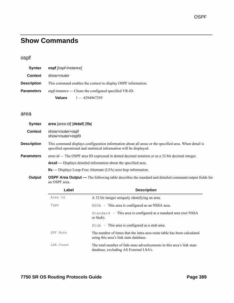
OSPF
Show Commands
ospf
Syntax ospf [ospf-instance]
Context show>router
Description This command enables the context to display OSPF information.
Parameters ospf-instance — Clears the configured specified VR-ID.
Values 1 — 4294967295
area
Syntax area [area-id] [detail] [lfa]
Context show>router>ospfshow>router>ospf3
Description This command displays configuration information about all areas or the specified area. When detail is specified operational and statistical information will be displayed.
Parameters area-id — The OSPF area ID expressed in dotted decimal notation or as a 32-bit decimal integer.
detail — Displays detailed information about the specified area.
lfa — Displays Loop-Free Alternate (LFA) next-hop information.
Output OSPF Area Output — The following table describes the standard and detailed command output fields for an OSPF area.
Label Description
Area Id A 32 bit integer uniquely identifying an area.
Type NSSA — This area is configured as an NSSA area.
Standard — This area is configured as a standard area (not NSSA or Stub).
Stub — This area is configured as a stub area.
SPF Runs The number of times that the intra-area route table has been calculated using this area’s link state database.
LSA Count The total number of link-state advertisements in this area’s link state database, excluding AS External LSA’s.
7750 SR OS Routing Protocols Guide Page 389

Show Commands
Sample Output
A:SetupCLI# show router ospf area detail===============================================================================OSPF Areas (Detailed)===============================================================================-------------------------------------------------------------------------------Area Id: 0.0.0.0-------------------------------------------------------------------------------Area Id : 0.0.0.0 Type : StandardKey Rollover Int.: 10 LFA : IncludeVirtual Links : 0 Total Nbrs : 0Active IFs : 0 Total IFs : 2
LSA Cksum Sum The 32-bit unsigned sum of the link-state database advertisements LS checksums contained in this area’s link state database. This checksum excludes AS External LSAs (type-5).
No. of OSPF Areas The number of areas configured on the router.
Virtual Links The number of virtual links configured through this transit area.
Active IFs The active number of interfaces configured in this area.
Area Bdr Rtrs The total number of ABRs reachable within this area.
AS Bdr Rtrs The total number of ASBRs reachable within this area.
Last SPF Run The time when the last intra-area SPF was run on this area.
Router LSAs The total number of router LSAs in this area.
Network LSAs The total number of network LSAs in this area.
Summary LSAs The summary of LSAs in this area.
Asbr-summ LSAs The summary of ASBR LSAs in this area.
Nssa-ext LSAs The total number of NSSA-EXT LSAs in this area.
Area opaque LSAs The total number of opaque LSAs in this area.
Total Nbrs The total number of neighbors in this area.
Total IFs The total number of interfaces configured in this area.
Total LSAs The sum of LSAs in this area excluding autonomous system external LSAs.
Blackhole Range False — No blackhole route is installed for aggregates configured in this area.
True — A lowest priority blackhole route is installed for aggregates configured in this area.
Label Description (Continued)
Page 390 7750 SR OS Routing Protocols Guide

OSPF
Area Bdr Rtrs : 0 AS Bdr Rtrs : 0SPF Runs : 0 Last SPF Run : NeverRouter LSAs : 0 Network LSAs : 0Summary LSAs : 0 Asbr-summ LSAs : 0Nssa ext LSAs : 0 Area opaque LSAs : 1Total LSAs : 1 LSA Cksum Sum : 0xd6afBlackhole Range : True Unknown LSAs : 0-------------------------------------------------------------------------------Area Id: 1.1.1.1-------------------------------------------------------------------------------Area Id : 1.1.1.1 Type : StubDefault Cost : 16777215 Import Summary : Send SummaryKey Rollover Int.: 10 LFA : ExcludeVirtual Links : 0 Total Nbrs : 0Active IFs : 0 Total IFs : 1Area Bdr Rtrs : 0 AS Bdr Rtrs : 0SPF Runs : 0 Last SPF Run : NeverRouter LSAs : 0 Network LSAs : 0Summary LSAs : 0 Asbr-summ LSAs : 0Nssa ext LSAs : 0 Area opaque LSAs : 1Total LSAs : 1 LSA Cksum Sum : 0xf493Blackhole Range : False Unknown LSAs : 0-------------------------------------------------------------------------------Area Id: 2.2.2.2-------------------------------------------------------------------------------Area Id : 2.2.2.2 Type : StandardKey Rollover Int.: 10 LFA : IncludeVirtual Links : 1 Total Nbrs : 0Active IFs : 0 Total IFs : 0Area Bdr Rtrs : 0 AS Bdr Rtrs : 0SPF Runs : 0 Last SPF Run : NeverRouter LSAs : 0 Network LSAs : 0Summary LSAs : 0 Asbr-summ LSAs : 0Nssa ext LSAs : 0 Area opaque LSAs : 1Total LSAs : 1 LSA Cksum Sum : 0xd6afBlackhole Range : True Unknown LSAs : 0===============================================================================A:SetupCLI#
A:SR# show router ospf area detail ===============================================================================OSPF Areas (Detailed)===============================================================================-------------------------------------------------------------------------------Area Id: 0.0.0.0-------------------------------------------------------------------------------Area Id : 0.0.0.0 Type : Standard Virtual Links : 0 Total Nbrs : 2 Active IFs : 3 Total IFs : 3 Area Bdr Rtrs : 0 AS Bdr Rtrs : 0 SPF Runs : 7 Last SPF Run : 10/26/2006 10:09:18 Router LSAs : 3 Network LSAs : 3 Summary LSAs : 0 Asbr-summ LSAs : 0 Nssa ext LSAs : 0 Area opaque LSAs : 3 Total LSAs : 9 LSA Cksum Sum : 0x28b62 Blackhole Range : True Unknown LSAs : 0 ===============================================================================*A:Bombadil# show router ospf area 0.0.0.0 detail
7750 SR OS Routing Protocols Guide Page 391

Show Commands
===============================================================================OSPF Area (Detailed) : 0.0.0.0===============================================================================-------------------------------------------------------------------------------Configuration-------------------------------------------------------------------------------Area Id : 0.0.0.0 Type : Standard -------------------------------------------------------------------------------Statistics-------------------------------------------------------------------------------Virtual Links : 0 Total Nbrs : 2 Active IFs : 3 Total IFs : 3 Area Bdr Rtrs : 0 AS Bdr Rtrs : 0 SPF Runs : 7 Last SPF Run : 10/26/2006 10:09:18 Router LSAs : 3 Network LSAs : 3 Summary LSAs : 0 Asbr-summ LSAs : 0 Nssa ext LSAs : 0 Area opaque LSAs : 3 Total LSAs : 9 LSA Cksum Sum : 0x28b62 Blackhole Range : True Unknown LSAs : 0 ===============================================================================
*A:Dut-B# show router ospf area 0.0.0.0 lfa=======================================================================Path Table=======================================================================Node Interface Nexthop LFA Interface LFA Nexthop-----------------------------------------------------------------------10.20.1.1 to_Dut-A1 10.20.1.1 to_Dut-C1 10.20.1.310.20.1.3 to_Dut-C1 10.20.1.3 to_Dut-A1 10.20.1.110.20.1.4 to_Dut-D1 10.20.1.410.20.1.6 to_Dut-D1 10.20.1.4 to_Dut-C1 10.20.1.3=======================================================================*A:Dut-B#
*A:Dut-B# show router ospf area 0.0.0.0 lfa detail=======================================================================Path Table=======================================================================OSPF Area : 0.0.0.0-----------------------------------------------------------------------Node : 10.20.1.1 Metric : 10Interface : to_Dut-A1 Nexthop : 10.20.1.1LFA Interface : to_Dut-C1 LFA Metric : 20LFA type : linkProtection LFA Nexthop : 10.20.1.3
Node : 10.20.1.3 Metric : 10Interface : to_Dut-C1 Nexthop : 10.20.1.3LFA Interface : to_Dut-A1 LFA Metric : 20LFA type : linkProtection LFA Nexthop : 10.20.1.1
Node : 10.20.1.4 Metric : 10
Page 392 7750 SR OS Routing Protocols Guide

OSPF
Interface : to_Dut-D1 Nexthop : 10.20.1.4
Node : 10.20.1.6 Metric : 20Interface : to_Dut-D1 Nexthop : 10.20.1.4LFA Interface : to_Dut-C1 LFA Metric : 30LFA type : nodeProtection LFA Nexthop : 10.20.1.3
=======================================================================*A:Dut-B#
database
Syntax database [type {router | network | summary | asbr-summary | external | nssa | all}] [area area-id] [adv-router router-id] [link-state-id] [detail]
Context show>router>ospfshow>router>ospf3
Description This command displays information about the OSPF link state database (LSDB).
When no command line options are specified, the command displays brief output for all database entries
Parameters ospf-instance — The OSPF instance.
Values 1 — 4294967295
type keyword — Specifies to filter the OSPF LSDB information based on the type specified by keyword.
type router — Display only router (Type 1) LSAs in the LSDB.
type network — Display only network (Type 2) LSAs in the LSDB.
type summary — Display only summary (Type 3) LSAs in the LSDB.
type asbr-summary — Display only ASBR summary (Type 4) LSAs in the LSDB.
type external — Display only AS external (Type 5) LSAs in the LSDB. External LSAs are maintained globally and not per area. If the display of external links is requested, the area parameter, if present, is ignored.
type nssa — Displays only NSSA area-specific AS external (Type 7) LSAs in the LSDB.
type all — Display all LSAs in the LSDB. The all keyword is intended to be used with either the area area-id or the adv-router router-id [link-state-id] parameters.
area area-id — Display LSDB information associated with the specified OSPF area-id.
adv-router router-id [link-state-id] — Display LSDB information associated with the specified advertising router. To further narrow the number of items displayed, the link-state-id can optionally be specified.
detail — Displays detailed information on the LSDB entries.
7750 SR OS Routing Protocols Guide Page 393

Show Commands
Output OSPF Database Ouput — The following table describes the standard and detailed command output fields for an OSPF database.
Label Description
Area Id The OSPF area identifier.
TypeLSA Type
Router — LSA type of router (OSPF)
Network — LSA type of network (OSPF)
Summary — LSA type of summary (OSPF)
ASBR Summary — LSA type of ASBR summary (OSPF)
Nssa-ext — LSA area-specific, NSSA external (OSPF)
Area opaque — LSA type of area opaque (OSPF)
router — LSA type of router (OSPF3)
Network — LSA type of network (OSPF3)
IE Pfx — LSA type of IE Pfx (OSPF3)IE Rtr — LSA type of IE Rtr (OSPF3)
IA Pfx — LSA type of IA Pfx (OSPF3)
Nssa-ext — NSSA area-specific AS external (OSPF3)
Link State Id The link state Id is an LSA type specific field containing either a num-ber to distinguish several LSAs from the same router, an interface ID, or a router-id; it identifies the piece of the routing domain being described by the advertisement.
Adv Rtr IdAdv Router Id
The router identifier of the router advertising the LSA.
Age The age of the link state advertisement in seconds.
SequenceSequence No
The signed 32-bit integer sequence number.
CksumChecksum
The 32-bit unsigned sum of the link-state advertisements' LS check-sums.
No. of LSAs The number of LSAs displayed.
Options EA — External Attribute LSA Support
DC — Demand Circuit Support
R — If clear, a node can participates in OSPF topology distribution without being used to forward transit traffic.
N — Type 7 LSA Support
Page 394 7750 SR OS Routing Protocols Guide

OSPF
Sample Output
A:ALA-A# show router ospf 1 database===============================================================================OSPF Link State Database (Type : All)===============================================================================Area Id Type Link State Id Adv Rtr Id Age Sequence Cksum-------------------------------------------------------------------------------0.0.0.0 Router 180.0.0.2 180.0.0.2 1800 0x800000b6 0xf540.0.0.0 Router 180.0.0.5 180.0.0.5 1902 0x8000009d 0xcb7c0.0.0.0 Router 180.0.0.8 180.0.0.8 1815 0x8000009a 0x529b0.0.0.0 Router 180.0.0.9 180.0.0.9 1156 0x80000085 0xd00f0.0.0.0 Router 180.0.0.10 180.0.0.10 533 0x8000009d 0x3f1f0.0.0.0 Router 180.0.0.11 180.0.0.11 137 0x80000086 0xc58f0.0.0.0 Router 180.0.0.12 180.0.0.12 918 0x8000009d 0x4cf30.0.0.0 Router 180.0.0.13 180.0.0.13 1401 0x800000a2 0x879c0.0.0.0 Network 180.0.53.28 180.0.0.28 149 0x80000083 0xe5cd0.0.0.0 Network 180.0.54.28 180.0.0.28 1259 0x80000083 0xdad70.0.0.0 Summary 180.0.0.15 180.0.0.10 378 0x80000084 0xeba1
MC — Multicast Support
E — External Routes Support
V6 — V6 works in conjunction with R. If V6 is clear, a node can par-ticipate in OSPF topology distribution without being used to forward IPv6 datagrams. If R is set and V6 is clear, IPv6 datagrams are not for-warded but diagrams belonging to another protocol family may be for-warded.
Prefix Options P — Propagate NSSA LSA.
MC — Multicast support.
LA — Lcal address capability. If set, the prefix is an IPv6 interface address of the advertising router.
NU — No unicast capability. If set, the prefix is excluded from IPv6 unicast calculations.
Flags None — No flags setV — The router is an endpoint for one or more fully adjacent Virtual Links having the described area as the transit areaE — The router is an AS Boundary RouterB — The router is an Area Border Router
Link Count The number of links advertised in the LSA.
Link Type (n) The link type of the nth link in the LSA.
Network (n) The network address of the nth link in the LSA.
Metric-0 (n) The cost metric of the nth link in the LSA.
Label Description (Continued)
7750 SR OS Routing Protocols Guide Page 395

Show Commands
0.0.0.0 Summary 180.0.0.15 180.0.0.12 73 0x80000084 0xdfab0.0.0.0 Summary 180.0.0.18 180.0.0.10 1177 0x80000083 0xcfbb0.0.0.1 Summary 180.100.25.4 180.0.0.12 208 0x80000091 0x30490.0.0.1 AS Summ 180.0.0.8 180.0.0.10 824 0x80000084 0x3d070.0.0.1 AS Summ 180.0.0.8 180.0.0.12 1183 0x80000095 0x4bdf0.0.0.1 AS Summ 180.0.0.9 180.0.0.10 244 0x80000082 0x73cbn/a AS Ext 7.1.0.0 180.0.0.23 1312 0x80000083 0x45e7n/a AS Ext 7.2.0.0 180.0.0.23 997 0x80000082 0x45e6n/a AS Ext 10.20.0.0 180.0.0.23 238 0x80000081 0x2d81...-------------------------------------------------------------------------------No. of LSAs: 339===============================================================================A:ALA-A#
A:ALA-A# show router ospf database detail===============================================================================OSPF Link State Database (Type : All) (Detailed)-------------------------------------------------------------------------------Router LSA for Area 0.0.0.0-------------------------------------------------------------------------------Area Id : 0.0.0.0 Adv Router Id : 180.0.0.2Link State Id : 180.0.0.2 LSA Type : RouterSequence No : 0x800000b7 Checksum : 0xd55Age : 155 Length : 192Options : EFlags : None Link Count : 14Link Type (1) : Point To PointNbr Rtr Id (1) : 180.0.0.13 I/F Address (1) : 180.0.22.2No of TOS (1) : 0 Metric-0 (1) : 25Link Type (2) : Stub NetworkNetwork (2) : 180.0.22.0 Mask (2) : 255.255.255.0No of TOS (2) : 0 Metric-0 (2) : 25Link Type (3) : Point To PointNbr Rtr Id (3) : 180.0.0.12 I/F Address (3) : 180.0.5.2No of TOS (3) : 0 Metric-0 (3) : 25Link Type (4) : Stub NetworkNetwork (4) : 180.0.5.0 Mask (4) : 255.255.255.0No of TOS (4) : 0 Metric-0 (4) : 25Link Type (5) : Point To PointNbr Rtr Id (5) : 180.0.0.8 I/F Address (5) : 180.0.13.2No of TOS (5) : 0 Metric-0 (5) : 6Link Type (6) : Stub NetworkNetwork (6) : 180.0.13.0 Mask (6) : 255.255.255.0No of TOS (6) : 0 Metric-0 (6) : 6Link Type (7) : Point To PointNbr Rtr Id (7) : 180.0.0.5 I/F Address (7) : 180.0.14.2No of TOS (7) : 0 Metric-0 (7) : 6Link Type (8) : Stub NetworkNetwork (8) : 180.0.14.0 Mask (8) : 255.255.255.0No of TOS (8) : 0 Metric-0 (8) : 6Link Type (9) : Point To PointNbr Rtr Id (9) : 180.0.0.11 I/F Address (9) : 180.0.17.2No of TOS (9) : 0 Metric-0 (9) : 25Link Type (10) : Stub NetworkNetwork (10) : 180.0.17.0 Mask (10) : 255.255.255.0No of TOS (10) : 0 Metric-0 (10) : 25Link Type (11) : Stub Network
Page 396 7750 SR OS Routing Protocols Guide

OSPF
Network (11) : 180.0.0.2 Mask (11) : 255.255.255.255No of TOS (11) : 0 Metric-0 (11) : 1Link Type (12) : Stub NetworkNetwork (12) : 180.0.18.0 Mask (12) : 255.255.255.0No of TOS (12) : 0 Metric-0 (12) : 24Link Type (13) : Point To PointNbr Rtr Id (13) : 180.0.0.10 I/F Address (13) : 180.0.3.2No of TOS (13) : 0 Metric-0 (13) : 25Link Type (14) : Stub NetworkNetwork (14) : 180.0.3.0 Mask (14) : 255.255.255.0No of TOS (14) : 0 Metric-0 (14) : 25-------------------------------------------------------------------------------AS Ext LSA for Network 180.0.0.14-------------------------------------------------------------------------------Area Id : N/A Adv Router Id : 180.0.0.10Link State Id : 180.0.0.14 LSA Type : AS ExtSequence No : 0x80000083 Checksum : 0xa659Age : 2033 Length : 36Options : ENetwork Mask : 255.255.255.255 Fwding Address : 180.1.6.15Metric Type : Type 2 Metric-0 : 4Ext Route Tag : 0-------------------------------------------------------------------------------...A:ALA-A#
interface
Syntax interface [ip-addr | ip-int-name | area area-id] [detail]
Context show>router>ospfshow>router>ospf3
Description Displays the details of the OSPF interface, this interface can be identified by ip-address or ip interface name. When neither is specified, all in-service interfaces are displayed.
The detail option produces a great amount of data. It is recommended to detail only when requesting a specific interface.
Parameters ip-addr — Display only the interface identified by this IP address.
ip-int-name — Display only the interface identified by this interface name.
area area-id — Display all interfaces configured in this area.
detail — Displays detailed information on the interface.
Output Standard OSPF Interface Output — The following table describes the standard command output fields for an OSPF interface.
Label Description
If Name The interface name.
Area Id A 32-bit integer uniquely identifying the area to which this interface is connected. Area ID 0.0.0.0 is used for the OSPF backbone.
7750 SR OS Routing Protocols Guide Page 397

Show Commands
Sample Output
A:SetupCLI# show router ospf interface "ip_if_1" detail===============================================================================OSPF Interface (Detailed) : ip_if_1===============================================================================-------------------------------------------------------------------------------Configuration-------------------------------------------------------------------------------IP Address : 10.10.1.1Area Id : 0.0.0.0 Priority : 10Hello Intrvl : 9 sec Rtr Dead Intrvl : 45 secRetrans Intrvl : 10 sec Poll Intrvl : 120 secCfg Metric : 11 Advert Subnet : TrueTransit Delay : 2 Auth Type : MD5Passive : False Cfg MTU : 9198LFA : ExcludeIPsec InStatSA : IPsec OutStatSA :IPsec InStatSATmp:-------------------------------------------------------------------------------State
D Rtr Id The IP Interface address of the router identified as the Designated Router for the network in which this interface is configured. Set to 0.0.0.0 if there is no Designated router.
BD Rtr Id The IP Interface address of the router identified as the Backup Desig-nated Router for the network in which this interface is configured. Set to 0.0.0.0 if there is no Backup Designated router.
Adm Dn — OSPF on this interface is administratively shut down.
Up — OSPF on this interface is administratively enabled.
Opr Down — This is the initial interface state. In this state, the lower-level protocols have indicated that the interface is unusable.
Wait — The router is trying to determine the identity of the (Backup) Designated router for the network.
PToP — The interface is operational, and connects either to a physi-cal point-to-point network or to a virtual link.
DR — This router is the Designated Router for this network.
BDR — This router is the backup Designated Router for this network.
ODR — The interface is operational and part of a broadcast or NBMA network on which another router has been selected to be the Desig-nated Router.
No. of OSPF Inter-faces
The number of interfaces listed.
Label Description (Continued)
Page 398 7750 SR OS Routing Protocols Guide

OSPF
-------------------------------------------------------------------------------Admin Status : Enabled Oper State : DownDesignated Rtr : 0.0.0.0 Backup Desig Rtr : 0.0.0.0IF Type : Secondary Network Type : StubOper MTU : 1576 Last Enabled : NeverOper Metric : 11 Bfd Enabled : NoTe Metric : 16777215 Te State : DownAdmin Groups : NoneLdp Sync : outOfService Ldp Sync Wait : DisabledLdp Timer State : Disabled Ldp Tm Left : 0-------------------------------------------------------------------------------Statistics-------------------------------------------------------------------------------Nbr Count : 0 If Events : 0Tot Rx Packets : 0 Tot Tx Packets : 0Rx Hellos : 0 Tx Hellos : 0Rx DBDs : 0 Tx DBDs : 0Rx LSRs : 0 Tx LSRs : 0Rx LSUs : 0 Tx LSUs : 0Rx LS Acks : 0 Tx LS Acks : 0Retransmits : 0 Discards : 0Bad Networks : 0 Bad Virt Links : 0Bad Areas : 0 Bad Dest Addrs : 0Bad Auth Types : 0 Auth Failures : 0Bad Neighbors : 0 Bad Pkt Types : 0Bad Lengths : 0 Bad Hello Int. : 0Bad Dead Int. : 0 Bad Options : 0Bad Versions : 0 Bad Checksums : 0LSA Count : 0 LSA Checksum : 0x0-------------------------------------------------------------------------------Configuration-------------------------------------------------------------------------------IP Address : 10.10.1.1Area Id : 1.1.1.1 Priority : 10Hello Intrvl : 9 sec Rtr Dead Intrvl : 45 secRetrans Intrvl : 10 sec Poll Intrvl : 120 secCfg Metric : 11 Advert Subnet : FalseTransit Delay : 2 Auth Type : MD5Passive : False Cfg MTU : 9198LFA : ExcludeIPsec InStatSA : IPsec OutStatSA :IPsec InStatSATmp:-------------------------------------------------------------------------------State-------------------------------------------------------------------------------Admin Status : Enabled Oper State : DownDesignated Rtr : 0.0.0.0 Backup Desig Rtr : 0.0.0.0IF Type : Point To Point Network Type : StubOper MTU : 1576 Last Enabled : NeverOper Metric : 11 Bfd Enabled : NoTe Metric : 16777215 Te State : DownAdmin Groups : NoneLdp Sync : outOfService Ldp Sync Wait : DisabledLdp Timer State : Disabled Ldp Tm Left : 0-------------------------------------------------------------------------------Statistics-------------------------------------------------------------------------------Nbr Count : 0 If Events : 0Tot Rx Packets : 0 Tot Tx Packets : 0
7750 SR OS Routing Protocols Guide Page 399

Show Commands
Rx Hellos : 0 Tx Hellos : 0Rx DBDs : 0 Tx DBDs : 0Rx LSRs : 0 Tx LSRs : 0Rx LSUs : 0 Tx LSUs : 0Rx LS Acks : 0 Tx LS Acks : 0Retransmits : 0 Discards : 0Bad Networks : 0 Bad Virt Links : 0Bad Areas : 0 Bad Dest Addrs : 0Bad Auth Types : 0 Auth Failures : 0Bad Neighbors : 0 Bad Pkt Types : 0Bad Lengths : 0 Bad Hello Int. : 0Bad Dead Int. : 0 Bad Options : 0Bad Versions : 0 Bad Checksums : 0LSA Count : 0 LSA Checksum : 0x0===============================================================================A:SetupCLI#
A:SetupCLI# show router ospf interface area 1.1.1.1 detail===============================================================================OSPF Interfaces in Area (Detailed) : 1.1.1.1===============================================================================-------------------------------------------------------------------------------Interface : ip_if_1-------------------------------------------------------------------------------IP Address : 10.10.1.1Area Id : 1.1.1.1 Priority : 10Hello Intrvl : 9 sec Rtr Dead Intrvl : 45 secRetrans Intrvl : 10 sec Poll Intrvl : 120 secCfg Metric : 11 Advert Subnet : FalseTransit Delay : 2 Auth Type : MD5Passive : False Cfg MTU : 9198LFA : ExcludeIPsec InStatSA : IPsec OutStatSA :IPsec InStatSATmp:Admin Status : Enabled Oper State : DownDesignated Rtr : 0.0.0.0 Backup Desig Rtr : 0.0.0.0IF Type : Point To Point Network Type : StubOper MTU : 1576 Last Enabled : NeverOper Metric : 11 Bfd Enabled : NoTe Metric : 16777215 Te State : DownAdmin Groups : NoneLdp Sync : outOfService Ldp Sync Wait : DisabledLdp Timer State : Disabled Ldp Tm Left : 0Nbr Count : 0 If Events : 0Tot Rx Packets : 0 Tot Tx Packets : 0Rx Hellos : 0 Tx Hellos : 0Rx DBDs : 0 Tx DBDs : 0Rx LSRs : 0 Tx LSRs : 0Rx LSUs : 0 Tx LSUs : 0Rx LS Acks : 0 Tx LS Acks : 0Retransmits : 0 Discards : 0Bad Networks : 0 Bad Virt Links : 0Bad Areas : 0 Bad Dest Addrs : 0Bad Auth Types : 0 Auth Failures : 0Bad Neighbors : 0 Bad Pkt Types : 0Bad Lengths : 0 Bad Hello Int. : 0Bad Dead Int. : 0 Bad Options : 0Bad Versions : 0 Bad Checksums : 0
Page 400 7750 SR OS Routing Protocols Guide

OSPF
LSA Count : 0 LSA Checksum : 0x0===============================================================================A:SetupCLI#
A:SetupCLI# show router ospf 1 interface detail===============================================================================OSPF Interfaces (Detailed)-------------------------------------------------------------------------------Interface : system-------------------------------------------------------------------------------IP Address : 9.1.255.255Area Id : 0.0.0.0 Priority : 1Hello Intrvl : 10 sec Rtr Dead Intrvl : 40 secRetrans Intrvl : 5 sec Poll Intrvl : 120 secCfg Metric : 0 Advert Subnet : TrueTransit Delay : 1 Auth Type : NonePassive : True Cfg MTU : 0Admin Status : Enabled Oper State : Designated RtrDesignated Rtr : 2.2.2.2 Backup Desig Rtr : 0.0.0.0IF Type : Broadcast Network Type : TransitOper MTU : 1500 Last Enabled : 05/14/2006 09:16:26Oper Metric : 0 Bfd Enabled : NoNbr Count : 0 If Events : 5Tot Rx Packets : 0 Tot Tx Packets : 0Rx Hellos : 0 Tx Hellos : 0Rx DBDs : 0 Tx DBDs : 0Rx LSRs : 0 Tx LSRs : 0Rx LSUs : 0 Tx LSUs : 0Rx LS Acks : 0 Tx LS Acks : 0Retransmits : 0 Discards : 0Bad Networks : 0 Bad Virt Links : 0Bad Areas : 0 Bad Dest Addrs : 0Bad Auth Types : 0 Auth Failures : 0Bad Neighbors : 0 Bad Pkt Types : 0Bad Lengths : 0 Bad Hello Int. : 0Bad Dead Int. : 0 Bad Options : 0Bad Versions : 0 Bad Checksums : 0LSA Count : 0 LSA Checksum : 0x0-------------------------------------------------------------------------------Interface : sender-------------------------------------------------------------------------------IP Address : 11.1.1.1Area Id : 0.0.0.0 Priority : 1Hello Intrvl : 10 sec Rtr Dead Intrvl : 40 secRetrans Intrvl : 5 sec Poll Intrvl : 120 secCfg Metric : 0 Advert Subnet : TrueTransit Delay : 1 Auth Type : NonePassive : False Cfg MTU : 0===============================================================================A:SetupCLI#
Detailed OSPF Interface Output — The following table describes the detailed command output fields for an OSPF interface.
Label Description
Interface The IP address of this OSPF interface.
7750 SR OS Routing Protocols Guide Page 401

Show Commands
IP Address The IP address and mask of this OSPF interface.
Interface Name The interface name.
Area Id A 32-bit integer uniquely identifying the area to which this interface is connected. Area ID 0.0.0.0 is used for the OSPF backbone.
Priority The priority of this interface. Used in multi-access networks, this field is used in the designated router election algorithm.
Hello Intrvl The length of time, in seconds, between the Hello packets that the router sends on the interface. This value must be the same for all rout-ers attached to a common network.
Rtr Dead Intrvl The number of seconds that a router's Hello packets have not been seen before it's neighbors declare the router down. This should be some multiple of the Hello interval. This value must be the same for all rout-ers attached to a common network.
Retrans Intrvl The number of seconds between link-state advertisement retransmis-sions, for adjacencies belonging to this interface. This value is also used when retransmitting database description and link-state request packets.
Poll Intrvl The larger time interval, in seconds, between the Hello packets sent to an inactive non-broadcast multi-access neighbor.
Metric The metric to be advertised for this interface.
Advert Subnet False — When a point-to-point interface is configured as false, then the subnet is not advertised and the endpoints are advertised as host routes.
True — When a point-to-point interface is configured to true, then the subnet is advertised.
Transit Delay The estimated number of seconds it takes to transmit a link state update packet over this interface.
Auth Type Identifies the authentication procedure to be used for the packet.
None — Routing exchanges over the network/subnet are not authen-ticated.
Simple — A 64-bit field is configured on a per-network basis. All packets sent on a particular network must have this configured value in their OSPF header 64-bit authentication field. This essentially serves as a “clear” 64-bit password.
Label Description (Continued)
Page 402 7750 SR OS Routing Protocols Guide

OSPF
MD5 — A shared secret key is configured in all routers attached to a common network/subnet. For each OSPF protocol packet, the key is used to generate/verify a “message digest” that is appended to the end of the OSPF packet.
Passive False — This interfaces operates as a normal OSPF interface with regard to adjacency forming and network/link behavior.
True — no OSPF HELLOs will be sent out on this interface and the router advertises this interface as a stub network/link in its router LSAs.
MTU The desired size of the largest packet which can be sent/received on this OSPF interface, specified in octets. This size DOES include the underlying IP header length, but not the underlying layer headers/trail-ers.
Admin Status Disabled — OSPF on this interface is administratively shut down.
Enabled — OSPF on this interface is administratively enabled.
Oper State Down — This is the initial interface state. In this state, the lower-level protocols have indicated that the interface is unusable.
Waiting — The router is trying to determine the identity of the (Backup) Designated router for the network.
Point To Point — The interface is operational, and connects either to a physical point-to-point network or to a virtual link.
Designated Rtr — This router is the Designated Router for this network.
Other Desig Rtr — The interface is operational and part of a broadcast or NBMA network on which another router has been selected to be the Designated Router.
Backup Desig Rtr — This router is the Backup Designated Router for this network.
DR-Id The IP Interface address of the router identified as the Designated Router for the network in which this interface is configured. Set to 0.0.0.0 if there is no Designated router
BDR-Id The IP Interface address of the router identified as the Backup Desig-nated Router for the network in which this interface is configured. Set to 0.0.0.0 if there is no Backup Designated router.
IF Type Broadcast — LANs, such as Ethernet.
NBMA — X.25, Frame Relay and similar technologies.
Label Description (Continued)
7750 SR OS Routing Protocols Guide Page 403

Show Commands
Point-To-Point — Links that are definitively point to point.
Network Type Stub — OPSF has not established a neighbor relationship with any other OSPF router on this network as such only traffic sourced or des-tined to this network will be routed to this network.
Transit — OPSF has established at least one neighbor relationship with any other OSPF router on this network as such traffic en route to other networks may be routed via this network.
Oper MTU The operational size of the largest packet which can be sent/received on this OSPF interface, specified in octets. This size DOES include the underlying IP header length, but not the underlying layer headers/trail-ers.
Last Enabled The time that this interface was last enabled to run OSPF on this inter-face.
Nbr Count The number of OSPF neighbors on the network for this interface.
If Events The number of times this OSPF interface has changed its state, or an error has occurred since this interface was last enabled.
Tot Rx Packets The total number of OSPF packets received on this interface since this interface was last enabled.
Tot Tx Packets The total number of OSPF packets transmitted on this interface since this interface was last enabled.
Rx Hellos The total number of OSPF Hello packets received on this interface since this interface was last enabled.
Tx Hellos The total number of OSPF Hello packets transmitted on this interface since this interface was last enabled.
Rx DBDs The total number of OSPF database description packets received on this interface since this interface was last enabled.
Tx DBDs The total number of OSPF database description packets transmitted on this interface since this interface was last enabled.
Rx LSRs The total number of Link State Requests (LSRs) received on this inter-face since this interface was last enabled.
Tx LSRs The total number of Link State Requests (LSRs) transmitted on this interface since this interface was last enabled.
Rx LSUs The total number of Link State Updates (LSUs) received on this inter-face since this interface was last enabled.
Tx LSUs The total number of Link State Updates (LSUs) transmitted on this interface since this interface was last enabled.
Label Description (Continued)
Page 404 7750 SR OS Routing Protocols Guide

OSPF
Rx LS Acks The total number of Link State Acknowledgements received on this interface since this interface was last enabled.
Tx LS Acks The total number of Link State Acknowledgements transmitted on this interface since this interface was last enabled.
Retransmits The total number of OSPF Retransmits sent on this interface since this interface was last enabled.
Discards The total number of OSPF packets discarded on this interface since this interface was last enabled.
Bad Networks The total number of OSPF packets received with invalid network or mask since this interface was last enabled.
Bad Virt Links The total number of OSPF packets received on this interface that are destined to a virtual link that does not exist since this interface was last enabled.
Bad Areas The total number of OSPF packets received with an area mismatch since this interface was last enabled.
Bad Dest Addrs The total number of OSPF packets received with the incorrect IP desti-nation address since this interface was last enabled.
Bad Auth Types The total number of OSPF packets received with an invalid authoriza-tion type since this interface was last enabled.
Auth Failures The total number of OSPF packets received with an invalid authoriza-tion key since this interface was last enabled.
Bad Neighbors The total number of OSPF packets received where the neighbor infor-mation does not match the information this router has for the neighbor since this interface was last enabled.
Bad Pkt Types The total number of OSPF packets received with an invalid OSPF packet type since this interface was last enabled
Bad Lengths The total number of OSPF packets received on this interface with a total length not equal to the length given in the packet itself since this interface was last enabled.
Bad Hello int. The total number of OSPF packets received where the hello interval given in packet was not equal to that configured on this interface since this interface was last enabled.
Bad Dead Int. The total number of OSPF packets received where the dead interval given in the packet was not equal to that configured on this interface since this interface was last enabled.
Label Description (Continued)
7750 SR OS Routing Protocols Guide Page 405

Show Commands
Sample Output
*A:JC-NodeA# show router ospf interface area 1 detail===============================================================================OSPF Interfaces in Area (Detailed) : 1===============================================================================Interface : ip-10.10.1.1-------------------------------------------------------------------------------IP Address : 10.10.1.1Area Id : 0.0.0.1 Priority : 1Hello Intrvl : 5 sec Rtr Dead Intrvl : 15 secRetrans Intrvl : 5 sec Poll Intrvl : 120 secCfg Metric : 0 Advert Subnet : TrueTransit Delay : 1 Auth Type : NonePassive : False Cfg MTU : 0Admin Status : Enabled Oper State : Designated RtrDesignated Rtr : 10.20.1.1 Backup Desig Rtr : 0.0.0.0IF Type : Broadcast Network Type : TransitOper MTU : 1500 Last Enabled : 04/11/2007 16:06:27Oper Metric : 1000 Bfd Enabled : NoNbr Count : 0 If Events : 5Tot Rx Packets : 0 Tot Tx Packets : 1116Rx Hellos : 0 Tx Hellos : 1116Rx DBDs : 0 Tx DBDs : 0
Bad Options The total number of OSPF packets received with an option that does not match those configured for this interface or area since this interface was last enabled.
Bad Versions The total number of OSPF packets received with bad OSPF version numbers since this interface was last enabled.
Te Metric Indicates the TE metric configured for this interface. This metric is flooded out in the TE metric sub-tlv in the OSPF TE LSAs. Depending on the configuration, either the TE metric value or the native OSPF metric value is used in CSPF computations.
Te State Indicates the MPLS interface TE status from OSPF standpoint.
Admin Groups Indicates the bit-map inherited from MPLS interface that identifies the admin groups to which this interface belongs.
Ldp Sync Specifies whether the IGP-LDP synchronization feature is enabled or disabled on all interfaces participating in the OSPF routing protocol.
Ldp Sync Wait Indicates the time to wait for the LDP adjacency to come up.
Ldp Timer State Indicates the state of the LDP sync time left on the OSPF interface.
Ldp Tm Left Indicates the time left before OSPF reverts back to advertising normal metric for this interface.
Label Description (Continued)
Page 406 7750 SR OS Routing Protocols Guide

OSPF
Rx LSRs : 0 Tx LSRs : 0Rx LSUs : 0 Tx LSUs : 0Rx LS Acks : 0 Tx LS Acks : 0Retransmits : 0 Discards : 0Bad Networks : 0 Bad Virt Links : 0Bad Areas : 0 Bad Dest Addrs : 0Bad Auth Types : 0 Auth Failures : 0Bad Neighbors : 0 Bad Pkt Types : 0Bad Lengths : 0 Bad Hello Int. : 0Bad Dead Int. : 0 Bad Options : 0Bad Versions : 0 Bad Checksums : 0LSA Count : 0 LSA Checksum : 0x0TE Metric : 678===============================================================================*A:JC-NodeA#
lfa-coverage
Syntax lfa-coverage
Context show>router>ospf
Description This command displays OSPF Loop-Free Alternate (LFA) next-hop information.
Sample Output
*A:Dut-A# show router ospf lfa-coverage=======================================================================LFA coverage ospfv2 instance 0=======================================================================Area Node Prefix---------------------------------------------------------------------------0.0.0.0 4/4(100%) 8/8(100%)=======================================================================*A:Dut-A#
neighbor
Syntax neighbor [ip-int-name ] [router-id]
Context show>router>ospfshow>router>ospf3
Description This command will display all neighbor information. To reduce the amount of output the user may opt to select the neighbors on a given interface by address or name.
The detail option produces a large amount of data. It is recommended to use detail only when requesting a specific neighbor.
7750 SR OS Routing Protocols Guide Page 407

Show Commands
Parameters ip-int-name — Display neighbor information only for neighbors of the interface identified by the interface name
router-id — Display neighbor information for the neighbor identified by the the specified router ID.
Output Standard OSPF Neighbor Output — The following table describes the standard command output fields for an OSPF neighbor.
Label Description
Nbr IP Addr The IP address this neighbor is using in its IP Source Address. Note that, on addressless links, this will not be 0.0.0.0, but the address of another of the neighbor's interfaces.
Nbr Rtr Id A 32-bit integer uniquely identifying the neighboring router in the Autonomous System.
Nbr State Down — This is the initial state of a neighbor conversation. It indi-cates that there has been no recent information received from the neighbor.
Attempt — This state is only valid for neighbors attached to NBMA networks. It indicates that no recent information has been received from the neighbor, but that a more concerted effort should be made to contact the neighbor.
Init — In this state, an Hello packet has recently been seen from the neighbor. However, bidirectional communication has not yet been established with the neighbor (i.e., the router itself did not appear in the neighbor's Hello packet).
Two Way — In this state, communication between the two routers is bidirectional.
ExchStart — This is the first step in creating an adjacency between the two neighboring routers. The goal of this step is to decide which router is the master, and to decide upon the initial Database Descriptor sequence number.
Exchange — In this state the router is describing its entire link state database by sending Database Description packets to the neighbor.
Loading — In this state, Link State Request packets are sent to the neighbor asking for the more recent LSAs that have been discovered (but not yet received) in the Exchange state.
Full — In this state, the neighboring routers are fully adjacent. These adjacencies will now appear in router-LSAs and network-LSAs.
Priority The priority of this neighbor in the designated router election algo-rithm. The value 0 signifies that the neighbor is not eligible to become the designated router on this particular network.
RetxQ Len The current length of the retransmission queue.
Page 408 7750 SR OS Routing Protocols Guide

OSPF
Sample Output
A:ALA-A# show router ospf 1 neighbor===============================================================================OSPF Neighbors===============================================================================Interface-Name Rtr Id State Pri RetxQ TTL-------------------------------------------------------------------------------pc157-2/1 10.13.8.158 Full 1 0 37pc157-2/2 10.13.7.165 Full 100 0 33pc157-2/3 10.13.6.188 Full 1 0 38-------------------------------------------------------------------------------No. of Neighbors: 3===============================================================================A:ALA-A#
Detailed OSPF Neighbor Output — The following table describes the detailed command output fields for an OSPF neighbor.
Dead Time The time until this neighbor is declared down, this timer is set to the dead router interval when a valid hello packet is received from the neighbor.
No. of Neighbors The number of adjacent OSPF neighbors on this interface.
Label Description
Neighbor IP Addr The IP address this neighbor is using in its IP source address. Note that, on addressless links, this will not be 0.0.0.0, but the address of another of the neighbor's interfaces.
Local IF IP Addr The IP address of this OSPF interface.
Area Id A 32-bit integer uniquely identifying the area to which this interface is connected. Area ID 0.0.0.0 is used for the OSPF backbone
Designated Rtr The IP Interface address of the router identified as the Designated Router for the network in which this interface is configured. Set to 0.0.0.0 if there is no Designated router.
Neighbor Rtr Id A 32-bit integer uniquely identifying the neighboring router in the AS.
Neighbor State Down — This is the initial state of a neighbor conversation. It indi-cates that there has been no recent information received from the neighbor
Attempt — This state is only valid for neighbors attached to NBMA networks. It indicates that no recent information has been received from the neighbor, but that a more concerted effort should be made to contact the neighbor.
Label Description (Continued)
7750 SR OS Routing Protocols Guide Page 409

Show Commands
Init — In this state, an Hello packet has recently been seen from the neighbor. However, bidirectional communication has not yet been established with the neighbor (i.e., the router itself did not appear in the neighbor's Hello packet).
Two Way — In this state, communication between the two routers is bidirectional.
Exchange start — This is the first step in creating an adjacency between the two neighboring routers. The goal of this step is to decide which router is the master, and to decide upon the initial Database Descriptor sequence number.
Exchange — In this state the router is describing its entire link state database by sending Database Description packets to the neighbor
Loading — In this state, Link State Request packets are sent to the neighbor asking for the more recent LSAs that have been discovered (but not yet received) in the Exchange state.
Full — In this state, the neighboring routers are fully adjacent. These adjacencies will now appear in router-LSAs and network-LSAs.
Priority The priority of this neighbor in the designated router election algo-rithm. The value 0 signifies that the neighbor is not eligible to become the designated router on this particular network.
Retrans Q Length The current length of the retransmission queue.
Options E — External Routes Support
MC — Multicast Support
N/P — Type 7 LSA Support
EA — External Attribute LSA Support
DC — Demand Circuit Support
O — Opaque LSA Support
Backup Desig Rtr The IP Interface address of the router identified as the Backup Desig-nated Router for the network in which this interface is configured. Set to 0.0.0.0 if there is no backup designated router.
Events The number of times this neighbor relationship has changed state, or an error has occurred.
Last Event Time The time when the last event occurred that affected the adjacency to the neighbor.
Label Description (Continued)
Page 410 7750 SR OS Routing Protocols Guide

OSPF
Sample Output
A:ALA-A# show router ospf neighbor detail===============================================================================OSPF Neighbors-------------------------------------------------------------------------------Neighbor Rtr Id : 10.13.8.158 Interface: pc157-2/1-------------------------------------------------------------------------------Neighbor IP Addr : 10.16.1.8Local IF IP Addr : 10.16.1.7Area Id : 0.0.0.0Designated Rtr : 0.0.0.0 Backup Desig Rtr : 0.0.0.0Neighbor State : Full Priority : 1
Up Time This value represents the uninterrupted time, in hundredths of seconds, the adjacency to this neighbor has been up. To evaluate when the last state change occurred see last event time.
Time Before Dead The time until this neighbor is declared down, this timer is set to the dead router interval when a valid hello packet is received from the neighbor.
Bad Nbr States The total number of OSPF packets received when the neighbor state was not expecting to receive this packet type since this interface was last enabled.
LSA Inst fails The total number of times an LSA could not be installed into the LSDB due to a resource allocation issue since this interface was last enabled.
Bad Seq Nums The total number of times when a database description packet was received with a sequence number mismatch since this interface was last enabled.
Bad MTUs The total number of times when the MTU in a received database description packet was larger than the MTU of the receiving interface since this interface was last enabled.
Bad Packets The total number of times when an LS update was received with an illegal LS type or an option mismatch since this interface was last enabled.
LSA not in LSDB The total number of times when an LS request was received for an LSA not installed in the LSDB of this router since this interface was last enabled.
Option Mismatches The total number of times when a LS update was received with an option mismatch since this interface was last enabled.
Nbr Duplicates The total number of times when a duplicate database description packet was received during the exchange state since this interface was last enabled.
Label Description (Continued)
7750 SR OS Routing Protocols Guide Page 411

Show Commands
Retrans Q Length : 0 Options : -E--O-Events : 4 Last Event Time : 05/06/2006 00:11:16Up Time : 1d 18:20:20 Time Before Dead : 38 secGR Helper : Not Helping GR Helper Age : 0 secGR Exit Reason : None GR Restart Reason: UnknownBad Nbr States : 1 LSA Inst fails : 0Bad Seq Nums : 0 Bad MTUs : 0Bad Packets : 0 LSA not in LSDB : 0Option Mismatches: 0 Nbr Duplicates : 0Num Restarts : 0 Last Restart at : Never-------------------------------------------------------------------------------Neighbor Rtr Id : 10.13.7.165 Interface: pc157-2/2-------------------------------------------------------------------------------Neighbor IP Addr : 10.12.1.3Local IF IP Addr : 10.12.1.7Area Id : 0.0.0.0Designated Rtr : 10.13.9.157 Backup Desig Rtr : 10.13.7.165Neighbor State : Full Priority : 100Retrans Q Length : 0 Options : -E--O-Events : 4 Last Event Time : 05/05/2006 01:39:13Up Time : 0d 16:52:27 Time Before Dead : 33 secGR Helper : Not Helping GR Helper Age : 0 secGR Exit Reason : None GR Restart Reason: UnknownBad Nbr States : 0 LSA Inst fails : 0Bad Seq Nums : 0 Bad MTUs : 0Bad Packets : 0 LSA not in LSDB : 0Option Mismatches: 0 Nbr Duplicates : 0Num Restarts : 0 Last Restart at : Never-------------------------------------------------------------------------------Neighbor Rtr Id : 10.13.6.188 Interface: pc157-2/3-------------------------------------------------------------------------------Neighbor IP Addr : 10.14.1.4Local IF IP Addr : 10.14.1.7Area Id : 0.0.0.0Designated Rtr : 10.13.9.157 Backup Desig Rtr : 10.13.6.188Neighbor State : Full Priority : 1Retrans Q Length : 0 Options : -E--O-Events : 4 Last Event Time : 05/05/2006 08:35:18Up Time : 0d 09:56:25 Time Before Dead : 38 secGR Helper : Not Helping GR Helper Age : 0 secGR Exit Reason : None GR Restart Reason: UnknownBad Nbr States : 1 LSA Inst fails : 0Bad Seq Nums : 0 Bad MTUs : 0Bad Packets : 0 LSA not in LSDB : 0Option Mismatches: 0 Nbr Duplicates : 0Num Restarts : 0 Last Restart at : Never===============================================================================A:ALA-A#
opaque-database
Syntax opaque-database [link link-id | area area-id |as] [adv-router router-id] [ls-id] [detail]
Context show>router>ospf
Description This command displays OSPF opaque database information.
Page 412 7750 SR OS Routing Protocols Guide
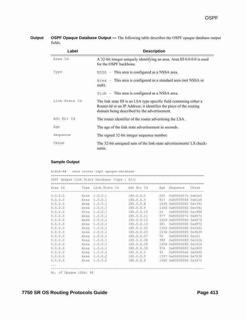
OSPF
Output OSPF Opaque Database Output — The following table describes the OSPF opaque database output fields.
Label Description
Area Id A 32-bit integer uniquely identifying an area. Area ID 0.0.0.0 is used for the OSPF backbone.
Type NSSA — This area is configured as a NSSA area.
Area — This area is configured as a standard area (not NSSA or stub).
Stub — This area is configured as a NSSA area.
Link State Id The link state ID is an LSA type specific field containing either a Router-Id or an IP Address; it identifies the piece of the routing domain being described by the advertisement.
Adv Rtr Id The router identifier of the router advertising the LSA.
Age The age of the link state advertisement in seconds.
Sequence The signed 32-bit integer sequence number.
Cksum The 32-bit unsigned sum of the link-state advertisements' LS check-sums.
Sample Output
A:ALA-A# show router ospf opaque-database===============================================================================OSPF Opaque Link State Database (Type : All)===============================================================================Area Id Type Link State Id Adv Rtr Id Age Sequence Cksum-------------------------------------------------------------------------------0.0.0.0 Area 1.0.0.1 180.0.0.2 205 0x8000007e 0xb1b20.0.0.0 Area 1.0.0.1 180.0.0.5 617 0x80000084 0xb1a60.0.0.0 Area 1.0.0.1 180.0.0.8 1635 0x80000081 0xc3910.0.0.0 Area 1.0.0.1 180.0.0.9 1306 0x80000082 0xc58c0.0.0.0 Area 1.0.0.1 180.0.0.10 53 0x80000082 0xc9860.0.0.0 Area 1.0.0.1 180.0.0.11 577 0x8000007e 0xd57c0.0.0.0 Area 1.0.0.1 180.0.0.12 1628 0x80000080 0xd5780.0.0.0 Area 1.0.0.1 180.0.0.13 581 0x80000080 0xd9720.0.0.0 Area 1.0.0.1 180.0.0.22 1006 0x80000080 0xfd3c0.0.0.0 Area 1.0.0.1 180.0.0.23 1238 0x80000083 0xfb390.0.0.0 Area 1.0.0.1 180.0.0.27 55 0x80000083 0xc210.0.0.0 Area 1.0.0.1 180.0.0.28 389 0x80000083 0x101b0.0.0.0 Area 1.0.0.1 180.0.0.29 1658 0x80000082 0x16140.0.0.0 Area 1.0.0.1 180.0.0.30 976 0x80000083 0x180f0.0.0.0 Area 1.0.0.2 180.0.0.2 45 0x800000a0 0x2f600.0.0.0 Area 1.0.0.2 180.0.0.5 1357 0x80000084 0x70380.0.0.0 Area 1.0.0.2 180.0.0.8 1960 0x80000084 0x3472...-------------------------------------------------------------------------------No. of Opaque LSAs: 88
7750 SR OS Routing Protocols Guide Page 413

Show Commands
===============================================================================A:ALA-A#
*A:Dut-A# show router ospf opaque-database adv-router 10.20.1.1 detail ==============================================================================OSPF Opaque Link State Database (Type : All) (Detailed)==============================================================================------------------------------------------------------------------------------Opaque LSA------------------------------------------------------------------------------Area Id : 0.0.0.0 Adv Router Id : 10.20.1.1 Link State Id : 1.0.0.1 LSA Type : Area Opaque Sequence No : 0x80000028 Checksum : 0xb136 Age : 192 Length : 28 Options : E Advertisement : ROUTER-ID TLV (0001) Len 4 : 10.20.1.1------------------------------------------------------------------------------Opaque LSA------------------------------------------------------------------------------Area Id : 0.0.0.0 Adv Router Id : 10.20.1.1 Link State Id : 1.0.0.2 LSA Type : Area Opaque Sequence No : 0x8000000d Checksum : 0x17f3 Age : 678 Length : 164 Options : E Advertisement : LINK INFO TLV (0002) Len 140 : Sub-TLV: 1 Len: 1 LINK_TYPE : 2 Sub-TLV: 2 Len: 4 LINK_ID : 10.10.1.2 Sub-TLV: 3 Len: 4 LOC_IP_ADDR : 10.10.1.1 Sub-TLV: 4 Len: 4 REM_IP_ADDR : 0.0.0.0 Sub-TLV: 5 Len: 4 TE_METRIC : 1000 Sub-TLV: 6 Len: 4 MAX_BDWTH : 100000 Kbps Sub-TLV: 7 Len: 4 RSRVBL_BDWTH : 800000 Kbps Sub-TLV: 8 Len: 32 UNRSRVD_CLS0 : P0: 80000 Kbps P1: 320000 Kbps P2: 320000 Kbps P3: 320000 Kbps P4: 400000 Kbps P5: 400000 Kbps P6: 400000 Kbps P7: 80000 Kbps Sub-TLV: 9 Len: 4 ADMIN_GROUP : 0 None Sub-TLV: 17 Len: 36 TELK_BW_CONST: BW Model : MAM BC0: 80000 Kbps BC1: 0 Kbps BC2: 320000 Kbps BC3: 0 Kbps BC4: 0 Kbps BC5: 400000 Kbps BC6: 0 Kbps BC7: 0 Kbps ==============================================================================*A:Dut-A#
Page 414 7750 SR OS Routing Protocols Guide

OSPF
range
Syntax range [area-id]
Context show>router>ospfshow>router>ospf3
Description This command displays ranges of addresses on an Area Border Router (ABR) for the purpose of route summarization or suppression.
Parameters area-id — Display the configured ranges for the specified area.
Output OSPF Range Output — The following table describes the OSPF range output fields.
Label Description
Area Id A 32-bit integer uniquely identifying an area. Area ID 0.0.0.0 is used for the OSPF backbone.
Address/Mask The mask for the range expressed as a decimal integer mask length or in dotted decimal notation.
Advertise False — The specified address/mask is not advertised outside the area.
True — The specified address/mask is advertised outside the area.
LSDB Type NSSA — This range was specified in the NSSA context, and specifies that the range applies to external routes (via type-7 LSAs) learned within the NSSA when the routes are advertised to other areas as type-5 LSAs.
Summary — This range was not specified in the NSSA context, the range applies to summary LSAs even if the area is an NSSA.
Sample Output
A:ALA-A# show router ospf 1 range==========================================================OSPF Ranges ==========================================================Area Id Address/Mask Advertise LSDB Type ----------------------------------------------------------No. of Ranges: 0 ==========================================================A:ALA-A#
A:ALA-A# show router ospf range 180.0.7.9==========================================================OSPF Ranges for Area Id : 180.0.7.9==========================================================Area Id Address/Mask Advertise LSDB Type----------------------------------------------------------No. of Ranges: 0
7750 SR OS Routing Protocols Guide Page 415

Show Commands
==========================================================A:ALA-A#
routes
Syntax routes [ip-prefix[/prefix-length]] [type] [detail] [alternative] [summary]
Context show>router>ospf
Description This command information about OSPF routes.
Parameters ip-prefix[/prefix-length — Displays information about the specified IP prefix and length.
type — Displays information about the specified type.
Values intra-area, inter-area, external-1, external-2, nssa-1, nssa-2
detail — Displays detailed information about the routes.
alternative — Displays the level of protection per prefix (ref. show router isis routes alternative)
summary — Displays summzarized information about the routes.
Sample Output
*A:Dut-A# show router ospf routes alternative detail=======================================================================OSPFv2 Routing Table (detailed)=======================================================================Destination Type(Dest) Stat NHIP NHIF Cost[E2] Area Tunnel-Information A-NHIP(L) A-NHIF A-Cost[E2] A-Type PGID-----------------------------------------------------------------------1.1.2.0/24 IA (NET) D (F) DIRECT 2 10 0.0.0.01.1.3.0/24 IA (NET) D (F) DIRECT 3 10 0.0.0.01.2.3.0/24 IA (NET) N (R) 1.1.2.2 2 20 0.0.0.0 1.1.3.3 3 20 0.0.0.01.2.4.0/24 IA (NET) N (R) 1.1.2.2 2 20 0.0.0.0 1.1.3.3(L) 3 30 LINK 0x1300151.3.5.0/24 IA (NET) N (R) 1.1.3.3 3 20 0.0.0.0 1.1.2.2(L) 2 30 LINK 0x1300161.4.5.0/24 IA (NET) N (R) 1.1.2.2 2 30 0.0.0.0 1.1.3.3 3 30 0.0.0.01.4.6.0/24 IA (NET) N (R) 1.1.2.2 2 30 0.0.0.0 1.1.3.3(L) 3 40 LINK 0x1300151.5.6.0/24 IA (NET) N (R) 1.1.3.3 3 30 0.0.0.0 1.1.2.2(L) 2 40 LINK 0x13001610.20.1.1/32 IA (HOST) D (F)
Page 416 7750 SR OS Routing Protocols Guide

OSPF
DIRECT 1 0 0.0.0.010.20.1.2/32 IA (HOST) N (R) 1.1.2.2 2 10 0.0.0.0 1.1.3.3(L) 3 20 LINK 0x13001510.20.1.3/32 IA (HOST) N (R) 1.1.3.3 3 10 0.0.0.0 1.1.2.2(L) 2 20 LINK 0x13001610.20.1.4/32 IA (HOST) N (R) 1.1.2.2 2 20 0.0.0.0 1.1.3.3(L) 3 30 LINK 0x13001510.20.1.5/32 IA (HOST) N (R) 1.1.3.3 3 20 0.0.0.0 1.1.2.2(L) 2 30 LINK 0x13001610.20.1.6/32 IA (HOST) N (R) 1.1.3.3 3 30 0.0.0.0 1.1.2.2 2 30 0.0.0.0
10.20.1.2/0 IA (RTR) N (N) 1.1.2.2 2 10 0.0.0.010.20.1.3/0 IA (RTR) N (N) 1.1.3.3 3 10 0.0.0.010.20.1.4/0 IA (RTR) N (N) 1.1.2.2 2 20 0.0.0.010.20.1.5/0 IA (RTR) N (N) 1.1.3.3 3 20 0.0.0.010.20.1.6/0 IA (RTR) N (N) 1.1.3.3 3 30 0.0.0.0 1.1.2.2 2 30 0.0.0.0-----------------------------------------------------------------------19 OSPFv2 routes found (23 paths)Flags: L = Loop-Free Alternate nexthop=======================================================================*A:Dut-A#
7750 SR OS Routing Protocols Guide Page 417

Show Commands
spf
Syntax spf [lfa]
Context show>router>ospfshow>router>ospf3
Description This command displays statistics of shortest-path-first (SPF) calculations.
Parameters lfa — Displays Loop-Free Alternate (LFA) next-hop information.
Output SPF Output Fields — The following table describes SPF output fields.
Label Description
Total SPF Runs The total number of incremental SPF runs triggered by new or updated LSAs.
Last Full SPF run @ The date and time when the external OSPF Dijkstra (SPF) was last run.
Last Full SPF Time The length of time, in seconds, when the last full SPF was run.
Intra SPF Time The time when intra-area SPF was last run on this area.
Inter SPF Time The total number of incremental SPF runs triggered by new or updated type-3 and type-4 summary LSAs.
Extern SPF Time The total number of incremental SPF runs triggered by new or updated type-5 external LSAs.
RTM Updt Time The time, in hundredths of seconds, used to perform a total SPF calcu-lation.
Min/Avg/Max Full SPF Time
Min — The minimum time, in hundredths of seconds, used to per-form a total SPF calculation.Avg — The average time, in hundredths of seconds, of all the total SPF calculations performed by this OSPF router.Max — The maximum time, in hundredths of seconds, used to per-form a total SPF calculation.
Total Sum Incr SPF Runs
The total number of incremental SPF runs triggered by new or updated type-3 and type-4 summary LSAs.
Total Ext Incr SPF Runs
The total number of incremental SPF runs triggered by new or updated type-5 external LSAs.
Sample Output
A:Dut-A# show router ospf spf lfa=======================================================================OSPF SPF Statistics======================================================================= Total SPF Runs : 6 Last Full SPF run @ : 02/20/2012 09:19:35
Page 418 7750 SR OS Routing Protocols Guide

OSPF
Last Full SPF Time : < 0.01 secs Intra SPF Time : < 0.01 secs Inter SPF Time : < 0.01 secs Extern SPF Time : < 0.01 secs RTM Updt Time : < 0.01 secs
Min/Avg/Max Full SPF Times : 0.00/0.00/0.00 secs Min/Avg/Max RTM Updt Times : 0.00/0.00/0.00 secs
Total Sum Incr SPF Runs : 0
Total Ext Incr SPF Runs : 0
Total LFA SPF Runs : 5 Last LFA SPF run @ : 02/20/2012 09:19:35 Last LFA SPF Time : < 0.01 secs Min/Avg/Max LFA SPF Times : 0.00/0.00/0.00 secs=======================================================================A:Dut-A#
A:ALA-A# show router ospf 1 spf===============================================================================OSPF SPF Statistics=============================================================================== Total SPF Runs : 109 Last Full SPF run @ : 11/07/2006 18:43:07 Last Full SPF Time : < 0.01 secs Intra SPF Time : < 0.01 secs Inter SPF Time : < 0.01 secs Extern SPF Time : < 0.01 secs RTM Updt Time : < 0.01 secs
Min/Avg/Max Full SPF Times : 0.02/0.00/0.06 secs Min/Avg/Max RTM Updt Times : 0.02/0.00/0.06 secs
Total Sum Incr SPF Runs : 333 Last Sum Incr SPF run @ : 11/07/2006 18:43:09 Last Sum Incr Calc Time : < 0.01 secs
Total Ext Incr SPF Runs : 0===============================================================================A:ALA-A#
7750 SR OS Routing Protocols Guide Page 419

Show Commands
statistics
Syntax statistics
Context show>router>ospfshow>router>ospf3
Description This command displays the global OSPF statistics.
Output OSPF Statistics Output Fields — The following table describes the command output fields for OSPF statistics.
Label Description
Rx Packets The total number of OSPF packets received on all OSPF enabled inter-faces.
Tx Packets The total number of OSPF packets transmitted on all OSPF enabled interfaces.
Rx Hellos The total number of OSPF Hello packets received on all OSPF enabled interfaces.
Tx Hellos The total number of OSPF Hello packets transmitted on all OSPF enabled interfaces.
Rx DBDs The total number of OSPF database description packets received on all OSPF enabled interfaces.
Tx DBDs The total number of OSPF database description packets transmitted on all OSPF enabled interfaces
Rx LSRs The total number of OSPF Link State Requests (LSRs) received on all OSPF enabled interfaces.
Tx LSRs The total number of OSPF Link State Requests (LSRs) transmitted on all OSPF enabled interfaces.
Rx LSUs The total number of OSPF Link State Update (LSUs) received on all OSPF enabled interfaces.
Tx LSUs The total number of OSPF Link State Update (LSUs) transmitted on all OSPF enabled interfaces.
Rx LS Acks The total number of OSPF Link State Acknowledgements (LSAs) received on all OSPF enabled interfaces.
New LSAs Recvd The total number of new OSPF Link State Advertisements received on all OSPF enabled interfaces.
New LSAs Orig The total number of new OSPF Link State Advertisements originated on all OSPF enabled interfaces.
Ext LSAs Count The total number of OSPF External Link State Advertisements.
Page 420 7750 SR OS Routing Protocols Guide

OSPF
No of Areas The number of areas configured for this OSPF instance.
Total SPF Runs The total number of incremental SPF runs triggered by new or updated LSAs.
Ext SPF Runs The total number of incremental SPF runs triggered by new or updated type-5 external LSAs.
Retransmits The total number of OSPF Retransmits transmitted on all OSPF enabled interfaces.
Discards The total number of OSPF packets discarded on all OSPF enabled interfaces.
Bad Networks The total number of OSPF packets received on all OSPF enabled inter-faces with invalid network or mask.
Bad Virt Links The total number of OSPF packets received on all OSPF enabled inter-faces that are destined to a virtual link that does not exist.
Bad Areas The total number of OSPF packets received on all OSPF enabled inter-faces with an area mismatch
Bad Dest Addrs The total number of OSPF packets received on all OSPF enabled inter-faces with the incorrect IP destination address.
Bad Auth Types The total number of OSPF packets received on all OSPF enabled inter-faces with an invalid authorization type.
Auth Failures The total number of OSPF packets received on all OSPF enabled inter-faces with an invalid authorization key.
Bad Neighbors The total number of OSPF packets received on all OSPF enabled inter-faces where the neighbor information does not match the information this router has for the neighbor.
Bad Pkt Types The total number of OSPF packets received on all OSPF enabled inter-faces with an invalid OSPF packet type.
Bad Lengths The total number of OSPF packets received on all OSPF enabled inter-faces with a total length not equal to the length given in the packet itself.
Bad Hello Int. The total number of OSPF packets received on all OSPF enabled inter-faces where the hello interval given in packet was not equal to that configured for the respective interface.
Bad Dead Int. The total number of OSPF packets received on all OSPF enabled inter-faces where the dead interval given in the packet was not equal to that configured for the respective interface.
Label Description
7750 SR OS Routing Protocols Guide Page 421

Show Commands
Sample Output
A:ALA-A# show router ospf 1 statistics===============================================================================OSPF Statistics===============================================================================Rx Packets : 308462 Tx Packets : 246800Rx Hellos : 173796 Tx Hellos : 149062Rx DBDs : 67 Tx DBDs : 48Rx LSRs : 21 Tx LSRs : 19Rx LSUs : 105672 Tx LSUs : 65530Rx LS Acks : 28906 Tx LS Acks : 32141New LSAs Recvd : 38113 New LSAs Orig : 21067Ext LSAs Count : 17 No of Areas : 3Total SPF Runs : 327 Ext SPF Runs : 0Retransmits : 46 Discards : 0Bad Networks : 0 Bad Virt Links : 0Bad Areas : 0 Bad Dest Addrs : 0Bad Auth Types : 0 Auth Failures : 0Bad Neighbors : 0 Bad Pkt Types : 0Bad Lengths : 0 Bad Hello Int. : 0Bad Dead Int. : 0 Bad Options : 0Bad Versions : 0 Bad Checksums : 0Failed SPF Attempts: 0CSPF Requests : 0 CSPF Request Drops : 0CSPF Path Found : 0 CSPF Path Not Found: 0===============================================================================A:ALA-A#
Bad Options The total number of OSPF packets received on all OSPF enabled inter-faces with an option that does not match those configured for the respective interface or area.
Bad Versions The total number of OSPF packets received on all OSPF enabled inter-faces with bad OSPF version numbers.
Label Description
Page 422 7750 SR OS Routing Protocols Guide

OSPF
status
Syntax status
Context show>router>ospfshow>router>ospf3
Description Displays the general status of OSPF.
Output OSPF Status Output Fields — The following table describes the command output fields for OSPF status.
Label Description
OSPF Router Id A 32-bit integer uniquely identifying the router in the Autonomous Sys-tem. The 7750 SR-Series defaults to the System IP address or if not configured the 32 least significant bits of the system MAC address.
OSPF Version The current version number of the OSPF protocol is 2.
OSPF Admin Status Disabled — Denotes that the OSPF process is disabled on all inter-faces.Enabled — Denotes that the OSPF process is active on at least one interface.
OSPF Oper Status Disabled — Denotes that the OSPF process is not operational on all interfaces.Enabled — Denotes that the OSPF process is operational on at least one interface.
Preference The route preference for OSPF internal routes.
External Prefer-ence
The route preference for OSPF external routes.
Backbone Router False — This variable indicates that this router is not configured as an OSPF back bone router.
True — This variable indicates that this router is configured as an OSPF back bone router.
Area Border Router False — This router is not an area border router.
True — This router is an area border router.
AS Border Router False — This router is not configured as an Autonomous System border router.
True — This router is configured as an Autonomous System border router.
OSPF Ldp Sync Admin Status
Indicates whether the IGP-LDP synchronization feature is enabled or disabled on all interfaces participating in the OSPF routing protocol.
7750 SR OS Routing Protocols Guide Page 423

Show Commands
Sample Output
A:SetupCLI# show router ospf status===============================================================================OSPF Status===============================================================================OSPF Cfg Router Id : 255.255.255.255OSPF Oper Router Id : 10.20.30.40OSPF Version : 2OSPF Admin Status : EnabledOSPF Oper Status : EnabledGraceful Restart : DisabledGR Helper Mode : DisabledPreference : 11External Preference : 150Backbone Router : TrueArea Border Router : FalseAS Border Router : TrueOpaque LSA Support : TrueTraffic Engineering Support : TrueRFC 1583 Compatible : TrueDemand Exts Support : FalseIn Overload State : True (Indefinitely in overload)In External Overflow State : FalseExit Overflow Interval : 0Last Overflow Entered : NeverLast Overflow Exit : 10/01/2011 07:34:03External LSA Limit : -1Reference Bandwidth : 10,000 KbpsInit SPF Delay : 10000 msecSec SPF Delay : 10000 msecMax SPF Delay : 12000 msecMin LS Arrival Interval : 600000 msecInit LSA Gen Delay : 100 msecSec LSA Gen Delay : 400 msecMax LSA Gen Delay : 600000 msecLast Ext SPF Run : NeverExt LSA Cksum Sum : 0x0OSPF Last Enabled : 10/01/2011 07:34:03Multicast Import : FalseExport Policies : test 567890123456789012345678901 : test 567890123456789012345678902 : test 567890123456789012345678903 : test 567890123456789012345678904 : test 567890123456789012345678905Import Policies : test 567890123456789012345678901 : test 567890123456789012345678902 : test 567890123456789012345678903 : test 567890123456789012345678904 : test 567890123456789012345678905OSPF Ldp Sync Admin Status : DisabledLDP-over-RSVP : EnabledRSVP-Shortcut : EnabledAdvertise-Tunnel-Link : EnabledLFA : EnabledExport Limit : 0Export Limit Log Percent : 0Total Exp Routes : 0===============================================================================
Page 424 7750 SR OS Routing Protocols Guide

OSPF
A:SetupCLI#
A:ALA-A# show router ospf 1 status===============================================================================OSPF Status===============================================================================OSPF Router Id : 10.13.7.165OSPF Version : 2OSPF Admin Status : EnabledOSPF Oper Status : EnabledGraceful Restart : EnabledGR Helper Mode : DisabledPreference : 10External Preference : 150Backbone Router : TrueArea Border Router : TrueAS Border Router : TrueOpaque LSA Support : TrueTraffic Engineering Support : TrueRFC 1583 Compatible : TrueTOS Routing Support : FalseDemand Exts Support : FalseIn Overload State : FalseIn External Overflow State : FalseExit Overflow Interval : 0Last Overflow Entered : NeverLast Overflow Exit : NeverExternal LSA Limit : -1Reference Bandwidth : 100,000,000 KbpsInit SPF Delay : 500 msecSec SPF Delay : 2000 msecMax SPF Delay : 15000 msecMin LS Arrival Interval : 500 msecMax LSA Gen Delay : 5000 msecLast Ext SPF Run : NeverExt LSA Cksum Sum : 0x2afceOSPF Last Enabled : 05/23/2006 23:34:36Export Policies : export-static===============================================================================A:ALA-A#
7750 SR OS Routing Protocols Guide Page 425

Show Commands
virtual-link
Syntax virtual-link [detail]
Context show>router>ospfshow>router>ospf3
Description This command displays information for OSPF virtual links.
Parameters detail — Provides operational and statistical information about virtual links associated with this router.
Output OSPF Virtual Link Output — The following table describes OSPF virtual-link output fields.
Label Description
Nbr Rtr ID The router ID(s) of neighboring routers.
Area Id A 32-bit integer which identifies an area.
Local Interface The IP address of the local egress interface used to maintain the adja-cency to reach this virtual neighbor.
Metric The metric value associated with the route. This value is used when importing this static route into other protocols. When the metric is con-figured as zero then the metric configured in OSPF, default-import-metric, applies. This value is also used to determine which static route to install in the forwarding table.
State The operational state of the virtual link to the neighboring router.
Authentication Specifies whether authentication is enabled for the interface or virtual link.
Hello Intrval Specifies the length of time, in seconds, between the Hello packets that the router sends on the interface.
Rtr Dead Intrvl Specifies the total number of OSPF packets received where the dead interval given in the packet was not equal to that configured on this interface since the OSPF admin status was enabled.
Tot Rx Packets Specifies the total number of OSPF packets received on this interface since the OSPF admin status was enabled.
Rx Hellos Specifies the total number of OSPF Hello packets received on this interface since the OSPF admin status was enabled.
Rx DBDs Specifies the total number of OSPF DataBase Description packets received on this interface since the OSPF administrative status was enabled.
Rx LSRs Specifies the total number of Link State Requests (LSRs) received on this interface since the OSPF admin status was enabled.
Page 426 7750 SR OS Routing Protocols Guide

OSPF
Rx LSUs Specifies the total number of Link State Updates (LSUs) received on this interface since the OSPF admin status was enabled.
Rx LS Acks Specifies the total number of Link State Acknowledgements received on this interface since the OSPF admin status was enabled.
Tot Tx Packets Specifies the total number of OSPF packets transmitted on this virtual interface since it was created.
Tx Hellos Specifies the total number of OSPF Hello packets transmitted on this virtual interface since it was created.
Tx DBDs Specifies the total number of OSPF database description packets trans-mitted on this virtual interface.
Tx LSRs Specifies the total number of OSPF Link State Requests (LSRs) trans-mitted on this virtual interface.
Tx LSUs Specifies the total number of OSPF Hello packets transmitted on this interface since the OSPF admin status was enabled.
Tx LS Acks Specifies the total number of OSPF Link State Acknowledgements (LSA) transmitted on this virtual interface.
Retransmits Specifies the total number of OSPF retransmits sent on this interface since the OSPF admin status was last enabled.
Discards Specifies the total number of OSPF packets discarded on this interface since the OSPF admin status was last enabled.
Bad Networks Specifies the total number of OSPF packets received with invalid net-work or mask since the OSPF admin status was last enabled.
Bad Versions Specifies the total number of OSPF packets received with bad OSPF version numbers since the OSPF admin status was last enabled.
Bad Areas Specifies the total number of OSPF packets received with an area mis-match since the OSPF admin status was last enabled.
Bad Dest Addrs Specifies the total number of OSPF packets received with the incorrect IP destination address since the OSPF admin status was last enabled.
Bad Auth Types Specifies the total number of OSPF packets received with an invalid authorization type since the OSPF admin status was last enabled.
Auth Failures Specifies the total number of OSPF packets received with an invalid authorization key since the OSPF admin status was last enabled.
Bad Neighbors Specifies the total number of OSPF packets received where the neigh-bor information does not match the information this router has for the neighbor since the OSPF admin status was last enabled.
Label Description (Continued)
7750 SR OS Routing Protocols Guide Page 427

Show Commands
Sample Output
A:ALA-A# show router ospf 1 virtual-link=================================================================OSPF Virtual Links=================================================================Nbr Rtr Id Area Id Local Interface Metric State-----------------------------------------------------------------180.0.0.10 0.0.0.1 180.1.7.12 300 PToP180.0.0.10 0.0.0.2 180.2.7.12 300 PToP-----------------------------------------------------------------No. of OSPF Virtual Links: 2=================================================================A:ALA-A#
A:ALA-A# show router ospf virtual-link detail===============================================================================OSPF Virtual Links (detailed)===============================================================================Neighbor Router Id : 180.0.0.10
Bad Pkt Types Specifies the total number of OSPF packets received with an invalid OSPF packet type since the OSPF admin status was last enabled.
Bad Lengths Specifies the total number of OSPF packets received on this interface with a total length not equal to the length given in the packet itself since the OSPF admin status was last enabled.
Bad Hello Int. Specifies the total number of OSPF packets received where the hello interval given in packet was not equal to that configured on this inter-face since the OSPF admin status was last enabled.
Bad Dead Int. Specifies the total number of OSPF packets received where the dead interval given in the packet was not equal to that configured on this interface since the OSPF admin status was last enabled.
Bad Options Specifies the total number of OSPF packets received with an option that does not match those configured for this interface or area since the OSPF admin status was last enabled.
Retrans Intrvl Specifies the length of time, in seconds, that OSPF waits before retransmitting an unacknowledged link state advertisement (LSA) to an OSPF neighbor.
Transit Delay Specifies the time, in seconds, that it takes to transmit a link state advertisement (LSA) on the interface or virtual link.
Last Event Specifies the date and time when an event was last associated with this OSPF interface.
Label Description (Continued)
Page 428 7750 SR OS Routing Protocols Guide

OSPF
-------------------------------------------------------------------------------Nbr Router Id : 180.0.0.10 Area Id : 0.0.0.1Local Interface: 180.1.7.12 Metric : 300State : Point To Point Admin State : UpHello Intrvl : 10 sec Rtr Dead Intrvl: 60 secTot Rx Packets : 43022 Tot Tx Packets : 42964Rx Hellos : 24834 Tx Hellos : 24853Rx DBDs : 3 Tx DBDs : 2Rx LSRs : 0 Tx LSRs : 0Rx LSUs : 15966 Tx LSUs : 16352Rx LS Acks : 2219 Tx LS Acks : 1757Retransmits : 0 Discards : 0Bad Networks : 0 Bad Versions : 0Bad Areas : 0 Bad Dest Addrs : 0Bad Auth Types : 0 Auth Failures : 0Bad Neighbors : 0 Bad Pkt Types : 0Bad Lengths : 0 Bad Hello Int. : 0Bad Dead Int. : 0 Bad Options : 0Retrans Intrvl : 5 sec Transit Delay : 1 secLast Event : 11/07/2006 17:11:56 Authentication : None-------------------------------------------------------------------------------Neighbor Router Id : 180.0.0.10-------------------------------------------------------------------------------Nbr Router Id : 180.0.0.10 Area Id : 0.0.0.2Local Interface: 180.2.7.12 Metric : 300State : Point To Point Admin State : UpHello Intrvl : 10 sec Rtr Dead Intrvl: 60 secTot Rx Packets : 43073 Tot Tx Packets : 43034Rx Hellos : 24851 Tx Hellos : 24844Rx DBDs : 3 Tx DBDs : 2Rx LSRs : 1 Tx LSRs : 1Rx LSUs : 18071 Tx LSUs : 17853Rx LS Acks : 147 Tx LS Acks : 334Retransmits : 0 Discards : 0Bad Networks : 0 Bad Versions : 0Bad Areas : 0 Bad Dest Addrs : 0Bad Auth Types : 0 Auth Failures : 0Bad Neighbors : 0 Bad Pkt Types : 0Bad Lengths : 0 Bad Hello Int. : 0Bad Dead Int. : 0 Bad Options : 0Retrans Intrvl : 5 sec Transit Delay : 1 secLast Event : 11/07/2006 17:12:00 Authentication : MD5===============================================================================A:ALA-A#
7750 SR OS Routing Protocols Guide Page 429

Show Commands
virtual-neighbor
Syntax virtual-neighbor [remote router-id] [detail]
Context show>router>ospfshow>router>ospf3
Description This command displays virtual neighbor information.
Parameters remote router-id — Displays the specified router ID. This reduces the amount of output displayed.
detail — Produces detailed information on the virtual neighbor. This option produces a large amount of data. It is recommended to use detail only when requesting information for a specific neighbor.
Output OSPF Virtual Neighbor Output — The following table describes OSPF virtual neighbor output fields.
Label Description
Nbr IP Addr The IP address this neighbor is using in its IP source address. Note that, on addressless links, this will not be 0.0.0.0, but the address of another of the neighbor's interfaces.
Nbr Rtr ID Specifies the router ID(s) of neighboring routers.
Transit Area Specifies the transit area ID that links the backbone area with the area that has no physical connection with the backbone.
Retrans Q Length The current length of the retransmission queue.
No. of Neighbors Specifies the total number of OSPF neighbors adjacent on this inter-face, in a state of INIT or greater, since the OSPF admin status was enabled.
Nbr State Specifies the operational state of the virtual link to the neighboring router.
Options Specifies the total number of OSPF packets received with an option that does not match those configured for this virtual interface or transit area since the OSPF admin status was enabled.
Events Specifies the total number of events that have occurred since the OSPF admin status was enabled.
Last Event Time Specifies the date and time when an event was last associated with this OSPF interface.
Up Time Specifies the uninterrupted time, in hundredths of seconds, the adja-cency to this neighbor has been up.
Time Before Dead Specifies the amount of time, in seconds, until the dead router interval expires.
Bad Nbr States Specifies the total number of OSPF packets received where the neigh-bor information does not match the information this router has for the neighbor since the OSPF admin status was last enabled.
Page 430 7750 SR OS Routing Protocols Guide

OSPF
Sample Output
A:ALA-A# show router ospf 1 virtual-neighbor===============================================================================OSPF Virtual Neighbors===============================================================================Nbr IP Addr Nbr Rtr Id Nbr State Transit Area RetxQ Len Dead Time-------------------------------------------------------------------------------180.1.6.10 180.0.0.10 Full 0.0.0.1 0 58180.2.9.10 180.0.0.10 Full 0.0.0.2 0 52-------------------------------------------------------------------------------No. of Neighbors: 2===============================================================================A:ALA-A#
A:ALA-A# show router ospf virtual-neighbor detail===============================================================================OSPF Virtual Neighbors===============================================================================Virtual Neighbor Router Id : 180.0.0.10-------------------------------------------------------------------------------Neighbor IP Addr : 180.1.6.10 Neighbor Rtr Id : 180.0.0.10Neighbor State : Full Transit Area : 0.0.0.1Retrans Q Length : 0 Options : -E--
LSA Inst fails Specifies the total number of times an LSA could not be installed into the LSDB due to a resource allocation issue since the OSPF admin sta-tus was last enabled.
Bad Seq Nums Specifies the total number of times when a database description packet was received with a sequence number mismatch since the OSPF admin status was last enabled.
Bad MTUs Specifies the total number of times when the MTU in a received data-base description packet was larger than the MTU of the receiving inter-face since the OSPF admin status was enabled.
Bad Packets Specifies the total number of times when an LS update was received with an illegal LS type or an option mismatch since the OSPF admin status was enabled.
LSA not in LSDB Specifies the total number of times when an LS request was received for an LSA not installed in the LSDB of this router since the OSPF admin status was enabled.
Option Mismatches Specifies the total number of times when a LS update was received with an option mismatch since the OSPF admin status was enabled.
Nbr Duplicates Specifies the total number of times when a duplicate database descrip-tion packet was received during the Exchange state since the OSPF admin status was enabled.
Label Description (Continued)
7750 SR OS Routing Protocols Guide Page 431

Show Commands
Events : 4 Last Event Time : 11/07/2006 17:11:56Up Time : 2d 17:47:17 Time Before Dead : 57 secBad Nbr States : 1 LSA Inst fails : 0Bad Seq Nums : 0 Bad MTUs : 0Bad Packets : 0 LSA not in LSDB : 0Option Mismatches: 0 Nbr Duplicates : 0-------------------------------------------------------------------------------Virtual Neighbor Router Id : 180.0.0.10-------------------------------------------------------------------------------Neighbor IP Addr : 180.2.9.10 Neighbor Rtr Id : 180.0.0.10Neighbor State : Full Transit Area : 0.0.0.2Retrans Q Length : 0 Options : -E--Events : 4 Last Event Time : 11/07/2006 17:11:59Up Time : 2d 17:47:14 Time Before Dead : 59 secBad Nbr States : 1 LSA Inst fails : 0Bad Seq Nums : 0 Bad MTUs : 0Bad Packets : 0 LSA not in LSDB : 0Option Mismatches: 0 Nbr Duplicates : 0===============================================================================A:ALA-A#
Page 432 7750 SR OS Routing Protocols Guide

OSPF
Clear Commands
ospf
Syntax ospf [ospf-instance]
Context clear>router
Description This command clears and resets OSPF protocol entities.
Parameters ospf-instance — Clears the configured specified VR-ID.
Values 1 — 4294967295
database
Syntax database [purge]
Context clear>router>ospfclear>router>ospf3
Description This command clears all LSAs received from other nodes.
Sets all adjacencies better then two way to one way.
Refreshes all self originated LSAs
Parameters purge — The purge parameter also clears all self-originated LSAs and re-originates all self-originated LSAs
export
Syntax export
Context clear>router>ospfclear>router>ospf3
Description Re-evaluates all effective export policies
neighbor
Syntax neighbor [ip-int-name | ip-address]
Context clear>router>ospfclear>router>ospf3
Description Marks the neighbor as dead and re-initiates the affected adjacencies.
7750 SR OS Routing Protocols Guide Page 433

Clear Commands
Parameters ip-int-name — Clear all neighbors for the interface specified by this interface name.
ip-address — Clear all neighbors for the interface specified by this IP-address
statistics
Syntax statistics
Context clear>router>ospfclear>router>ospf3
Description Clears all neighbor, router, interface, SPF and global statistics of this OSPF instance.
Page 434 7750 SR OS Routing Protocols Guide
OSPF
OSPF Debug Commands
ospf
Syntax ospf [ospf-instance]
Context debug>router
Description Indicates the OSPF instance for debugging purposes.
Parameters ospf-instance — The OSPF instance.
Values 1 — 31
area
Syntax area [area-id]no area
Context debug>router>ospfdebug>router>ospf3
Description This command enables debugging for an OSPF area.
Parameters area-id — Specify the OSPF area ID expressed in dotted decimal notation or as a 32-bit decimal integer.
area-range
Syntax area-range [ip-address]no area-range
Context debug>router>ospfdebug>router>ospf3
Description This command enables debugging for an OSPF area range.
Parameters ip-address — Specify the IP address for the range used by the ABR to advertise the area into another area.
7750 SR OS Routing Protocols Guide Page 435

OSPF Debug Commands
cspf
Syntax cspf [ip-address]no cspf
Context debug>router>ospfdebug>router>ospf3
Description This command enables debugging for an OSPF constraint-based shortest path first (CSPF).
Parameters ip-address — Specify the IP address for the range used for CSPF.
graceful-restart
Syntax [no] graceful-restart
Context debug>router>ospfdebug>router>ospf3
Description This command enables debugging for OSPF and OSPF3 graceful-restart.
interface
Syntax interface [ip-int-name | ip-address]no interface
Context debug>router>ospfdebug>router>ospf3
Description This command enables debugging for an OSPF and OSPF3 interface.
Parameters ip-int-name — Specify the IP interface name. An interface name cannot be in the form of an IP address. Interface names can be any string up to 32 characters long composed of printable, 7-bit ASCII characters. If the string contains special characters (#, $, spaces, etc.), the entire string must be enclosed within double quotes.
ip-address — Specify the interface’s IP address.
leak
Syntax leak [ip-address]no leak
Context debug>router>ospfdebug>router>ospf3
Description This command enables debugging for OSPF leaks.
Page 436 7750 SR OS Routing Protocols Guide
OSPF
Parameters ip-address — Specify the IP address to debug OSPF leaks.
lsdb
Syntax lsdb [type] [ls-id] [adv-rtr-id] [area area-id]no lsdb
Context debug>router>ospfdebug>router>ospf3
Description This command enables debugging for an OSPF link-state database (LSDB).
Parameters type — Specifies the OSPF link-state database (LSDB) type.
Values router, network, summary, asbr, extern, nssa, area-opaque, as-opaque, link-opaque
ls-id — Specifies an LSA type specific field containing either a router ID or an IP address. It identifies the piece of the routing domain being described by the advertisement.
adv-rtr-id — Specifies the router identifier of the router advertising the LSA.
area-id — Specifies a 32-bit integer uniquely identifying an area.
misc
Syntax [no] misc
Context debug>router>ospfdebug>router>ospf3
Description This command enables debugging for miscellaneous OSPF events.
neighbor
Syntax neighbor [ip-int-name | ip-address]no neighbor
Context debug>router>ospfdebug>router>ospf3
Description This command enables debugging for an OSPF or OSPF3 neighbor.
Parameters ip-int-name — Specifies the neighbor interface name.
ip-address — Specifies neighbor information for the neighbor identified by the the specified router ID.
7750 SR OS Routing Protocols Guide Page 437

OSPF Debug Commands
nssa-range
Syntax nssa-range [ip-address]no nssa-range
Context debug>router>ospfdebug>router>ospf3
Description This command enables debugging for an NSSA range.
Parameters ip-address — Specifies the IP address range to debug.
packet
Syntax packet [packet-type] [ip-address]no packet
Context debug>router>ospfdebug>router>ospf3
Description This command enables debugging for OSPF packets.
Parameters packet-type — Specifies the OSPF packet type to debug.
Values hello, dbdescr, lsrequest, lsupdate, lsack
ip-address — Specifies the IP address to debug.
Values ipv4-address: a.b.c.dipv6-address: x:x:x:x:x:x:x:x (eight 16-bit pieces)
x:x:x:x:x:x:d.d.d.dx: [0 — FFFF]H d: [0 — 255]D
rtm
Syntax rtm [ip-address]no rtm
Context debug>router>ospfdebug>router>ospf3
Description This command enables debugging for OSPF RTM.
Parameters ip-address — Specifies the IP address to debug.
Values ipv4-address: a.b.c.dipv6-address: x:x:x:x:x:x:x:x (eight 16-bit pieces)
x:x:x:x:x:x:d.d.d.dx: [0 — FFFF]H d: [0 — 255]D
Page 438 7750 SR OS Routing Protocols Guide

OSPF
spf
Syntax spf [type] [dest-addr]no spf
Context debug>router>ospf
Description This command enables debugging for OSPF SPF. Information regarding overall SPF start and stop times will be shown. To see detailed information regarding the SPF calculation of a given route, the route must be specified as an optional argument.
Parameters type — Specifies the area to debug
Values intra-area, inter-area, external
dest-addr — Specifies the destination IP address to debug.
virtual-neighbor
Syntax virtual-neighbor [ip-address]no virtual-neighbor
Context debug>router>ospf
Description This command enables debugging for an OSPF virtual neighbor.
Parameters ip-address — Specifies the IP address of the virtual neighbor.
7750 SR OS Routing Protocols Guide Page 439

OSPF Debug Commands
Page 440 7750 SR OS Routing Protocols Guide

IS-IS
In This Chapter
This chapter provides information to configure Intermediate System to Intermediate System (IS-IS).
Topics in this chapter include:
• Configuring IS-IS on page 442
Routing on page 443
IS-IS Frequently Used Terms on page 445
ISO Network Addressing on page 446
IS-IS PDU Configuration on page 448
IS-IS Operations on page 448
IS-IS Route Summarization on page 449
IS-IS Multi-Topology for IPv6 on page 450
IS-IS Administrative Tags on page 451
• IS-IS Configuration Process Overview on page 459
• Configuration Notes on page 460
7750 SR OS Routing Protocols Guide Page 441

Configuring IS-IS
Figure 15: IS-IS Routing Domain
Configuring IS-IS
Intermediate-system-to-intermediate-system (IS-IS) is a link-state interior gateway protocol (IGP) which uses the Shortest Path First (SPF) algorithm to determine routes. Routing decisions are made using the link-state information. IS-IS evaluates topology changes and, if necessary, performs SPF recalculations.
Entities within IS-IS include networks, intermediate systems, and end systems. In IS-IS, a network is an autonomous system (AS), or routing domain, with end systems and intermediate systems. A router, such as a 7750 SR-Series router, is an intermediate system. End systems are network devices which send and receive protocol data units (PDUs), the OSI term for packets. Intermediate systems send, receive, and forward PDUs.
End system and intermediate system protocols allow routers and nodes to identify each other. IS-IS sends out link-state updates periodically throughout the network, so each router can maintain current network topology information.
IS-IS supports large ASs by using a two-level hierarchy. A large AS can be administratively divided into smaller, more manageable areas. A system logically belongs to one area. Level 1 routing is performed within an area. Level 2 routing is performed between areas. 7750 SR-Series routers can be configured as Level 1, Level 2, or both Level 1/2.
Figure 15 displays an example of an IS-IS routing domain.
OSRG033
L1
L1
L1/2 L1/2
L1 L1
L2
L1
L1
L1/2 L1/2
Area A Area BLevel 2
Backbone
Area C
Page 442 7750 SR OS Routing Protocols Guide

IS-IS
Routing
OSI IS-IS routing uses two-level hierarchical routing. A routing domain can be partitioned into areas. Level 1 routers know the topology in their area, including all routers and end systems in their area but do not know the identity of routers or destinations outside of their area. Level 1 routers forward traffic with destinations outside of their area to a Level 2 router in their area.
Level 2 routers know the Level 2 topology, and know which addresses are reachable by each Level 2 router. Level 2 routers do not need to know the topology within any Level 1 area, except to the extent that a Level 2 router can also be a Level 1 router within a single area. By default, only Level 2 routers can exchange PDUs or routing information directly with external routers located outside the routing domain.
In IS-IS, there are two types of routers:
• Level 1 intermediate systems — Routing is performed based on the area ID portion of the ISO address called the network entity title (NET). Level 1 systems route within an area. They recognize, based on the destination address, whether the destination is within the area. If so, they route toward the destination. If not, they route to the nearest Level 2 router.
• Level 2 intermediate systems — Routing is performed based on the area address. They route toward other areas, disregarding other area’s internal structure. A Level 2 intermediate system can also be configured as a Level 1 intermediate system in the same area.
The Level 1 router’s area address portion is manually configured (see ISO Network Addressing on page 446). A Level 1 router will not become a neighbor with a node that does not have a common area address. However, if a Level 1 router has area addresses A, B, and C, and a neighbor has area addresses B and D, then the Level 1 router will accept the other node as a neighbor, as address B is common to both routers. Level 2 adjacencies are formed with other Level 2 nodes whose area addresses do not overlap. If the area addresses do not overlap, the link is considered by both routers to be Level 2 only and only Level 2 LSPDUs flow on the link.
Within an area, Level 1 routers exchange LSPs which identify the IP addresses reachable by each router. Specifically, zero or more IP address, subnet mask, and metric combinations can be included in each LSP. Each Level 1 router is manually configured with the IP address, subnet mask, and metric combinations, which are reachable on each interface. A Level 1 router routes as follows:
• If a specified destination address matches an IP address, subnet mask, or metric reachable within the area, the PDU is routed via Level 1 routing.
• If a specified destination address does not match any IP address, subnet mask, or metric combinations listed as reachable within the area, the PDU is routed towards the nearest Level 2 router.
7750 SR OS Routing Protocols Guide Page 443

Configuring IS-IS
Level 2 routers include in their LSPs, a complete list of IP address, subnet mask, and metrics specifying all the IP addresses which reachable in their area. This information can be obtained from a combination of the Level 1 LSPs (by Level 1 routers in the same area). Level 2 routers can also report external reachability information, corresponding to addresses reachable by routers in other routing domains or autonomous systems.
Page 444 7750 SR OS Routing Protocols Guide

IS-IS
IS-IS Frequently Used Terms
• Area — An area is a routing sub-domain which maintains detailed routing information about its own internal composition, and also maintains routing information which allows it to reach other routing sub-domains. Areas correspond to the Level 1 sub-domain.
• End system — End systems send NPDUs to other systems and receive NPDUs from other systems, but do not relay NPDUs. This International Standard does not specify any additional end system functions beyond those supplied by ISO 8473 and ISO 9542.
• Neighbor — A neighbor is an adjacent system reachable by traversing a single sub-network by a PDU.
• Adjacency — An adjacency is a portion of the local routing information which pertains to the reachability of a single neighboring end or intermediate system over a single circuit. Adjacencies are used as input to the decision process to form paths through the routing domain. A separate adjacency is created for each neighbor on a circuit and for each level of routing (Level 1 and Level 2) on a broadcast circuit.
• Circuit — The subset of the local routing information base pertinent to a single local Subnetwork Point of Attachments (SNPAs).
• Link — The communication path between two neighbors. A link is up when communication is possible between the two SNPAs.
• Designated IS — The intermediate system on a LAN which is designated to perform additional duties. In particular, the designated IS generates link-state PDUs on behalf of the LAN, treating the LAN as a pseudonode.
• Pseudonode — Where a broadcast sub-network has n connected intermediate systems, the broadcast sub-network itself is considered to be a pseudonode. The pseudonode has links to each of the n intermediate systems and each of the ISs has a single link to the pseudonode (rather than n-1 links to each of the other intermediate systems). Link-state PDUs are generated on behalf of the pseudonode by the designated IS.
• Broadcast sub-network — A multi-access subnetwork that supports the capability of addressing a group of attached systems with a single PDU.
• General topology sub-network — A topology that is modeled as a set of point-to-point links, each of which connects two systems. There are several generic types of general topology subnetworks, multipoint links, permanent point-to-point links, dynamic and static point-to-point links.
• Routing sub-domain — A routing sub-domain consists of a set of intermediate systems and end systems located within the same routing domain.
• Level 2 sub-domain — Level 2 sub-domain is the set of all Level 2 intermediate systems in a routing domain.
7750 SR OS Routing Protocols Guide Page 445

Configuring IS-IS
ISO Network Addressing
IS-IS uses ISO network addresses. Each address identifies a point of connection to the network, such as a router interface, and is called a Network Service Access Point (NSAP).
An end system can have multiple NSAP addresses, in which case the addresses differ only by the last byte (called the n-selector). Each NSAP represents a service that is available at that node. In addition to having multiple services, a single node can belong to multiple areas.
Each network entity has a special network address called a Network Entity Title (NET). Structurally, an NET is identical to an NSAP address but has an n-selector of 00. Most end systems have one NET. Intermediate systems can have up to three area IDs (area addresses).
NSAP addresses are divided into three parts. Only the area ID portion is configurable.
• Area ID — A variable length field between 1 and 13 bytes long. This includes the Authority and Format Identifier (AFI) as the most significant byte and the area ID.
• System ID — A six-byte system identification. This value is not configurable. The system ID is derived from the system or router ID.
• Selector ID — A one-byte selector identification that must contain zeros when configuring a NET. This value is not configurable. The selector ID is always 00.
Of the total 20 bytes comprising the NET, only the first 13 bytes, the area ID portion, can be manually configured. As few as one byte can be entered or, at most, 13 bytes. If less than 13 bytes are entered, the rest is padded with zeros.
Routers with common area addresses form Level 1 adjacencies. Routers with no common NET addresses form Level 2 adjacencies, if they are capable (Figure 16).
Page 446 7750 SR OS Routing Protocols Guide

IS-IS
Figure 16: Using Area Addresses to Form Adjacencies
OSRG034
L 1/2area 47.0001
area 48.0001
area 49.0001
L 1/2area 45.0001
area 46.0001
area 95.0001
L 1/2area 80.0001
area 79.0001
area 78.0001
L 1/2area 49.0001
area 80.0001
area 51.0001
L 1/2area 49.0001
area 87.0001
area 86.0001
L 1area 29.0001
area 50.0001
area 51.0001
L 1area 45.0001
area 28.0001
area 29.0001
L 1/2area 47.0001
area 32.0001
area 34.0001
L 1/2area 30.0001
area 31.0001
area 32.0001
7750 SR OS Routing Protocols Guide Page 447

Configuring IS-IS
IS-IS PDU Configuration
The following PDUs are used by IS-IS to exchange protocol information:
• IS-IS hello PDU — Routers with IS-IS enabled send hello PDUs to IS-IS-enabled interfaces to discover neighbors and establish adjacencies.
• Link-state PDUs — Contain information about the state of adjacencies to neighboring IS-IS systems. LSPs are flooded periodically throughout an area.
• Complete sequence number PDUs — In order for all routers to maintain the same information, CSNPs inform other routers that some LSPs can be outdated or missing from their database. CSNPs contain a complete list of all LSPs in the current IS-IS database.
• Partial sequence number PDUs (PSNPs) — PSNPs are used to request missing LSPs and acknowledge that an LSP was received.
IS-IS Operations
7750 SR-Series routers perform IS-IS routing as follows:
• Hello PDUs are sent to the IS-IS-enabled interfaces to discover neighbors and establish adjacencies.
• IS-IS neighbor relationships are formed if the hello PDUs contain information that meets the criteria for forming an adjacency.
• SRs can build a link-state PDU based upon their local interfaces that are configured for IS-IS and prefixes learned from other adjacent routers.
• SRs flood LSPs to the adjacent neighbors except the neighbor from which they received the same LSP. The link-state database is constructed from these LSPs.
• A Shortest Path Tree (SPT) is calculated by each IS, and from this SPT the routing table is built.
Page 448 7750 SR OS Routing Protocols Guide

IS-IS
IS-IS Route Summarization
IS-IS IPv4 route summarization allows users to create aggregate IPv4 addresses that include multiple groups of IPv4 addresses for a given IS-IS level. IPv4 Routes redistributed from other routing protocols also can be summarized. It is similar to the OSPF area-range command. IS-IS IPv4 route summarization helps to reduce the size of the LSDB and the IPv4 routing table, and it also helps to reduce the chance of route flapping.
IPv4 route summarization supports:
• Level 1, Level 1-2, and Level 2
• Route summarization for the IPv4 routes redistributed from other protocols
• Metric used to advertise the summary address will be the smallest metric of all the more specific IPv4 routes.
7750 SR OS Routing Protocols Guide Page 449

Configuring IS-IS
IS-IS Multi-Topology for IPv6
IS-IS IPv6 TLVs for IPv6 routing is supported in the 7750 SR-Series. This is considered native IPv6 routing with IS-IS. It has a limitation that IPv4 and IPv6 topologies must be congruent, otherwise traffic may be black holed. Service providers should ensure that the IPv4 topology and IPv6 topology are the same. With the 7750 SR-Series IS-IS multi-topology service providers can use different topologies for IPv4 and IPv6.
The implementation is compliant with draft-ietf-isis-wg-multi-topology-xx.txt, M-ISIS: Multi Topology (MT) Routing in IS-IS.
The following MT topologies are supported:
• MT ID #0: Equivalent to the standard IS-IS topology.
• MT ID #2: Reserved for IPv6 routing topology
Page 450 7750 SR OS Routing Protocols Guide

IS-IS
IS-IS Administrative Tags
IS-IS admin tags enable a network administrator to configure route tags to tag IS-IS route prefixes. These tags can subsequently be used to control Intermediate System-to-Intermediate System (IS-IS) route redistribution or route leaking.
The IS-IS support for route tags allows the tagging of IP addresses of an interface and use the tag to apply administrative policy with a route map. A network administrator can also tag a summary route and then use a route policy to match the tag and set one or more attributes for the route.
Using these administrative policies allow the operator to control how a router handles the routes it receives from and sends to its IS-IS neighboring routers. Administrative policies are also used to govern the installation of routes in the routing table.
Route tags allow:
• Policies to redistribute routes received from other protocols in the routing table to IS-IS.
• Policies to redistribute routes between levels in an IS-IS routing hierarchy.
• Policies to summarize routes redistributed into IS-IS or within IS-IS by creating aggregate (summary) addresses.
Setting Route Tags
IS-IS route tags are configurable in the following ways:
• Setting a route tag for an IS-IS interface.
• Setting a route tag on an IS-IS passive interface.
• Setting a route tag for a route redistributed from another protocol to IS-IS.
• Setting a route tag for a route redistributed from one IS-IS level to another IS-IS level.
• Setting a route tag for an IS-IS default route.
• Setting a route tag for an IS-IS summary address.
7750 SR OS Routing Protocols Guide Page 451

Configuring IS-IS
Using Route Tags
Although an operator on this or another (neighboring) IS-IS router has configured setting of the IS-IS administrative tags it will not have any effect unless policies are configure to instruct how to process the given tag value.
Policies can process tags where ISIS is either the origin, destination or both origin and destination protocol.
config>router>policy-options>policy-statement>entry>from config>router>policy-options>policy-statement>entry>action tag tag-value config>router>policy-options>policy-statement# default-action tag tag-value
Page 452 7750 SR OS Routing Protocols Guide

IS-IS
IP Fast-reroute (IP FRR) For IS-IS Prefixes
Refer to IP Fast-reroute (IP FRR) For OSPF and IS-IS Prefixes on page 307 for IP FRR for OSPF prefixes.
IP FRR Configuration
The user first enables Loop-Free Alternate (LFA) computation by SPF under the IS-IS routing protocol level or under the OSPF routing protocol instance level:
config>router>isis>loopfree-alternateconfig>router>ospf>loopfree-alternateconfig>service>vprn>ospf>loopfree-alternate
The above commands instruct the IGP SPF to attempt to pre-compute both a primary next-hop and an LFA next-hop for every learned prefix. When found, the LFA next-hop is populated into the RTM along with the primary next-hop for the prefix.
Next the user enables IP FRR to cause RTM to download to IOM a LFA next-hop, when found by SPF, in addition to the primary next-hop for each prefix in the FIB.
config>router>ip-fast-reroute
7750 SR OS Routing Protocols Guide Page 453

Configuring IS-IS
Reducing the Scope of the LFA Calculation by SPF
The user can instruct IGP to not include all interfaces participating in a specific IS-IS level or OSPF area in the SPF LFA computation. This provides a way of reducing the LFA SPF calculation where it is not needed.
config>router>isis>level>loopfree-alternate-exclude
config>router>ospf>area>loopfree-alternate-exclude
The user can also exclude a specific IP interface from being included in the LFA SPF computation by IS-IS or OSPF:
config>router>isis>interface> loopfree-alternate-exclude
config>router>ospf>area>interface> loopfree-alternate-exclude
Note that when an interface is excluded from the LFA SPF in IS-IS, it is excluded in both level 1 and level 2. When the user excludes an interface from the LFA SPF in OSPF, it is excluded in all areas. However, the above OSPF command can only be executed under the area in which the specified interface is primary and once enabled, the interface is excluded in that area and in all other areas where the interface is secondary. If the user attempts to apply it to an area where the interface is secondary, the command will fail.
Finally, the user can apply the same above commands for an OSPF instance within a VPRN service:
config>service>vprn>ospf>area>loopfree-alternate-exclude
config>service>vprn>ospf>area>interface>loopfree-alternate-exclude
ECMP Considerations
Whenever the SPF computation determined there is more than one primary next-hop for a prefix, it will not program any LFA next-hop in RTM. Thus, IP prefixes will resolve to the multiple primary next-hops in this case which provides the required protection.
IP FRR and RSVP Shortcut (IGP Shortcut)
IGP shortcuts are not supported in the LFA next-hop calculation.
Page 454 7750 SR OS Routing Protocols Guide

IS-IS
Figure 17: Example Topology with Primary and LFA Routes
The primary route is via R3. The LFA route via R2 has two equal cost paths to reach R5. The path via R3 protects against failure of link R1-R3. This route is computed by R1 by checking that the cost for R2 to reach R5 via R3 is lower than the cost via routes R1 and R3. This condition is referred to as the “loop-free criterion”.
The path via R2 and R4 can be used to protect against the failure of router R3. However, with the link R2-R3 metric set to 5, R2 sees the same cost to forward a packet to R5 via R3 and R4. Thus R1 cannot guarantee that enabling the LFA next-hop R2 will protect against R3 node failure. This
OSPF and IS-IS Support for Loop-Free Alternate Calculation
SPF computation in IS-IS and OSPF is enhanced to compute LFA alternate routes for each learned prefix and populate it in RTM.
Figure 17 illustrates a simple network topology with point-to-point (P2P) interfaces and highlights three routes to reach router R5 from router R1.
R1 R2
R3 R4
R5
5
5
5
5 (8)
5
5
Primary Route
LFA Link-Protect Route
LFA Node-Protect Route
7750 SR OS Routing Protocols Guide Page 455

Configuring IS-IS
Figure 18: Example Topology with Broadcast Interfaces
In order for next-hop R2 to be a link-protect LFA for route R5 from R1, it must be loop-free with respect to the R1-R3 link’s Pseudo-Node (PN). However, since R2 has also a link to that PN, its cost to reach R5 via the PN or router R4 are the same. Thus R1 cannot guarantee that enabling the LFA next-hop R2 will protect against a failure impacting link R1-PN since this may cause the entire subnet represented by the PN to go down. If the metric of link R2-PN is changed to 8, then R2 next-hop will be an LFA providing link protection.
means that the LFA next-hop R2 provides link-protection only for prefix R5. If the metric of link R2-R3 is changed to 8, then the LFA next-hop R2 provides node protection since a packet to R5 will always go over R4.
Consider now the case where the primary next-hop uses a broadcast interface as illustrated in Figure 18.
R1 R2
R3 R4
R5
5
5
55 (8)
5
5
Primary Route
LFA Link-Protect Route
PN
5
Page 456 7750 SR OS Routing Protocols Guide

IS-IS
The following are the detailed equations for this criterion as provided in RFC 5286, Basic Specification for IP Fast Reroute: Loop-Free Alternates:
• Link-protect backup next-hop (primary next-hop R1-R3 is a P2P interface):
Distance_opt(R2, R5) < Distance_opt(R2, R1) + Distance_opt(R1, R5)
• Node-protect backup next-hop (primary next-hop R1-R3 is a P2P interface):
Distance_opt(R2, R5) < Distance_opt(R2, R3) + Distance_opt(R3, R5)
• Link-protect backup next-hop (primary next-hop R1-R3 is a broadcast interface):
Distance_opt(R2, R5) < Distance_opt(R2, PN) + Distance_opt(PN, R5)
Where PN stands for the R1-R3 link’s Pseudo-Node.
For the case of P2P interface, if SPF finds multiple LFA next-hops for a given primary next-hop, it follows the following selection algorithm:
A) It will pick the node-protect type in favor of the link-protect type.
B) If there is more than one LFA next-hop within the selected type, then it will pick one based on the least cost.
C) If more than one LFA next-hop with the same cost results from step (b), then SPF will select the first one. This is not a deterministic selection and will vary following each SPF calculation.
For the case of a broadcast interface, a node-protect LFA is not necessarily a link protect LFA if the path to the LFA next-hop goes over the same PN as the primary next-hop. Similarly, a link protect LFA may not guarantee link protection if it goes over the same PN as the primary next-hop. The selection algorithm when SPF finds multiple LFA next-hops for a given primary next-hop is modified as follows:
A) The algorithm splits the LFA next-hops into two sets:
The first set consists of LFA next-hops which do not go over the PN used by primary next-hop,
The second set consists of LFA next-hops which go over the PN used by the primary next-hop.
B) If there is more than one LFA next-hop in the first set, it will pick the node-protect type in favor of the link-protect type.
C) If there is more than one LFA next-hop within the selected type, then it will pick one based on the least cost.
D) If more than one LFA next-hop with equal cost results from step (c), SPF will select the first one from the remaining set. This is not a deterministic selection and will vary following each SPF calculation.
7750 SR OS Routing Protocols Guide Page 457

Configuring IS-IS
E) If no LFA next-hop results from step (d), SPF will rerun steps (b-d) using the second set.
Note this algorithm is more flexible than strictly applying the link protect rule in the presence of a PN and specified in 5286. A node-protect LFA which does not avoid the PN, i.e., does not guarantee link protection, can still be selected as a last resort. The same thing, a link-protect LFA which does not avoid the PN may still be selected as a last resort.
Loop-Free Alternate Calculation for Inter-Area/inter-Level Prefixes
When SPF resolves OSPF inter-area prefixes or IS-IS inter-level prefixes, it will compute an LFA backup next-hop to the same exit area/border router as used by the primary next-hop.
Page 458 7750 SR OS Routing Protocols Guide

IS-IS
Figure 19: IS-IS Configuration and Implementation Flow
IS-IS Configuration Process Overview
Figure 19 displays the process to provision basic IS-IS parameters.
ENABLE
START
ENABLE IS-IS
SPECIFY AREA ADDRESSES
MODIFY LEVEL-CAPABILITY (OPTIONAL)
CONFIGURE INTERFACE PARAMETERS
CONFIGURE GLOBAL PARAMETERS
7750 SR OS Routing Protocols Guide Page 459

Configuration Notes
Configuration Notes
This section describes IS-IS configuration caveats.
General
• IS-IS must be enabled on each participating SR-Series .
• There are no default network entity titles.
• There are no default interfaces.
• By default, SR-Series routers are assigned a Level 1/Level 2 level capability.
Page 460 7750 SR OS Routing Protocols Guide

IS-IS
Configuring IS-IS with CLI
This section provides information to configure intermediate-system-to-intermediate-system (IS-IS) using the command line interface.
Topics in this section include:
• IS-IS Configuration Overview on page 462
Router Levels on page 462
Area Address Attributes on page 462
Interface Level Capability on page 463
Route Leaking on page 464
• Basic IS-IS Configuration on page 465
• Common Configuration Tasks on page 467
Enabling IS-IS on page 468
Modifying Router-Level Parameters on page 468
Configuring ISO Area Addresses on page 470
Configuring Global IS-IS Parameters on page 471
Configuring Interface Parameters on page 476
• IS-IS Configuration Management Tasks on page 481
Disabling IS-IS on page 481
Modifying Global IS-IS Parameters on page 482
Modifying IS-IS Interface Parameters on page 483
Example: Configuring a Level 1 Area on page 478
Example: Modifying a Router’s Level Capability on page 480
Configuring Leaking on page 485
Redistributing External IS-IS Routers on page 488
Specifying MAC Addresses for All IS-IS Routers on page 489
7750 SR OS Routing Protocols Guide Page 461

IS-IS Configuration Overview
IS-IS Configuration Overview
Router Levels
The router’s level capability can be configured globally and on a per-interface basis. The interface-level parameters specify the interface’s routing level. The neighbor capability and parameters define the adjacencies that are established.
IS-IS is not enabled by default. When IS-IS is enabled, the global default level capability is Level 1/2 which enables the router to operate as either a Level 1 and/or a Level 2 router with the associated databases. The router runs separate shortest path first (SPF) calculations for the Level 1 area routing and for the Level 2 multi-area routing to create the IS-IS routing table.
The level value can be modified on both or either of the global and interface levels to be only Level 1-capable, only Level 2-capable or Level 1 and Level 2-capable.
If the default value is not modified on any routers in the area, then the routers try to form both Level 1 and Level 2 adjacencies on all IS-IS interfaces. If the default values are modified to Level 1 or Level 2, then the number of adjacencies formed are limited to that level only.
Area Address Attributes
The area-id command specifies the area address portion of the NET which is used to define the IS-IS area to which the router will belong. At least one area-id command should be configured on each router participating in IS-IS. A maximum of three area-id commands can be configured per router.
The area address identifies a point of connection to the network, such as a router interface, and is called a network service access point (NSAP). The routers in an area manage routing tables about destinations within the area. The Network Entity Title (NET) value is used to identify the IS-IS area to which the router belongs.
NSAP addresses are divided into three parts. Only the Area ID portion is configurable.
1. Area ID — A variable length field between 1 and 13 bytes long. This includes the Authority and Format Identifier (AFI) as the most significant byte and the area ID.
2. System ID — A six-byte system identification. This value is not configurable. The system ID is derived from the system or router ID.
3. Selector ID — A one-byte selector identification that must contain zeros when configuring a NET. This value is not configurable. The selector ID is always 00.
Page 462 7750 SR OS Routing Protocols Guide

IS-IS
The following example displays ISO addresses in IS-IS address format:
MAC address 00:a5:c7:6b:c4:90 49.0011.00a5.c76b.c490.00IP address: 218.112.14.5 49.0011.2181.1201.4005.00
Interface Level Capability
The level capability value configured on the interface level is compared to the level capability value configured on the global level to determine the type of adjacencies that can be established. The default level capability for 7750 SR-Series routers and interfaces is Level 1/2.
Table 12 displays configuration combinations and the potential adjacencies that can be formed.
Table 12: Potential Adjacency Capabilities
Global Level Interface Level Potential Adjacency
L 1/2 L 1/2 Level 1 and/or Level 2
L 1/2 L 1 Level 1 only
L 1/2 L 2 Level 2 only
L 2 L 1/2 Level 2 only
L 2 L 2 Level 2 only
L 2 L 1 none
L 1 L 1/2 Level 1 only
L 1 L 2 none
L 1 L 1 Level 1 only
7750 SR OS Routing Protocols Guide Page 463

IS-IS Configuration Overview
Route Leaking
Alcatel-Lucent’s implementation of IS-IS route leaking is performed in compliance with RFC 2966, Domain-wide Prefix Distribution with Two-Level IS-IS. As previously stated, IS-IS is a routing domain (an autonomous system running IS-IS) which can be divided into Level 1 areas with a Level 2-connected subset (backbone) of the topology that interconnects all of the Level 1 areas. Within each Level 1 area, the routers exchange link state information. Level 2 routers also exchange Level 2 link state information to compute routes between areas.
Routers in a Level 1 area typically only exchange information within the Level 1 area. For IP destinations not found in the prefixes in the Level 1 database, the Level 1 router forwards PDUs to the nearest router that is in both Level 1/Level 2 with the attached bit set in its Level 1 link-state PDU.
There are many reasons to implement domain-wide prefix distribution. The goal of domain-wide prefix distribution is to increase the granularity of the routing information within the domain. The routing mechanisms specified in RFC 1195 are appropriate in many situations and account for excellent scalability properties. However, in certain circumstances, the amount of scalability can be adjusted which can distribute more specific information than described by RFC 1195.
Distributing more prefix information can improve the quality of the resulting routes. A well known property of default routing is that loss of information can occur. This loss of information affects the computation of a route based upon less information which can result in sub-optimal routes.
Page 464 7750 SR OS Routing Protocols Guide

IS-IS
Basic IS-IS Configuration
For IS-IS to operate on 7750 SR-Series routers, IS-IS must be explicitly enabled, and at least one area address and interface must be configured. If IS-IS is enabled but no area address or interface is defined, the protocol is enabled but no routes are exchanged. When at least one area address and interface are configured, then adjacencies can be formed and routes exchanged.
To configure IS-IS, perform the following tasks:
• Enable IS-IS.
• If necessary, modify the level capability on the global level (default is level-1/2).
• Define area address(es)
• Configure IS-IS interfaces.
The following output displays IS-IS default values.
A:Dut-A>config>router>isis$ info detail---------------------------------------------- level-capability level-1/2 no graceful-restart area-id 01 no authentication-key no authentication-type authentication-check csnp-authentication lsp-lifetime 1200 no export hello-authentication psnp-authentication traffic-engineering no reference-bandwidth no disable-ldp-sync ipv4-routing no ipv6-routing no unicast-import-disable no multicast-import spf-wait 10 1000 1000 no strict-adjacency-check lsp-wait 5 0 1 level 1 no authentication-key no authentication-type csnp-authentication external-preference 160 hello-authentication preference 15 psnp-authentication no wide-metrics-only exit level 2 no authentication-key no authentication-type
7750 SR OS Routing Protocols Guide Page 465

Basic IS-IS Configuration
csnp-authentication external-preference 165 hello-authentication preference 18 psnp-authentication no wide-metrics-only exit no shutdown----------------------------------------------A:Dut-A>config>router>isis$
Page 466 7750 SR OS Routing Protocols Guide

IS-IS
Common Configuration Tasks
To implement IS-IS in your network, you must enable IS-IS on each participating 7750 SR-Series router.
To assign different level capabilities to the routers and organize your network into areas, modify the level capability defaults on end systems from Level 1/2 to Level 1. Routers communicating to other areas can retain the Level 1/2 default.
On each router, at least one area ID also called the area address should be configured as well as at least one IS-IS interface.
• Enable IS-IS.
• Configure global IS-IS parameters.
Configure area address(es).
• Configure IS-IS interface-specific parameters.
7750 SR OS Routing Protocols Guide Page 467

Configuring IS-IS Components
Configuring IS-IS Components
Use the CLI syntax displayed below for:
• Enabling IS-IS on page 468
• Modifying Router-Level Parameters on page 468
• Configuring ISO Area Addresses on page 470
• Configuring Global IS-IS Parameters on page 471
• Configuring Interface Parameters on page 476
• Example: Configuring a Level 1 Area on page 478
• Example: Modifying a Router’s Level Capability on page 480
Enabling IS-IS
IS-IS must be enabled in order for the protocol to be active.
NOTE: Careful planning is essential to implement commands that can affect the behavior of global and interface levels.
To configure IS-IS on a router, enter the following command:
CLI Syntax: isis
Example: config>router# isis
Modifying Router-Level Parameters
When IS-IS is enabled, the default level-capability is Level 1/2. This means that the router operates with both Level 1 and Level 2 routing capabilities. To change the default value in order for the router to operate as a Level 1 router or a Level 2 router, you must explicitly modify the level value.
If the level is modified, the protocol shuts down and restarts. Doing this can affect adjacencies and routes.
The level-capability value can be configured on the global level and also on the interface level. The level-capability value determines which level values can be assigned on the router level or on an interface-basis.
Page 468 7750 SR OS Routing Protocols Guide

IS-IS
In order for the router to operate as a Level 1 only router or as a Level 2 only router, you must explicitly specify the level-number value.
• Select level-1 to route only within an area.
• Select level-2 to route to destinations outside an area, toward other eligible Level 2 routers.
To configure the router level, enter the following commands:
CLI Syntax: config>router# isislevel-capability {level-1|level-2|level-1/2}level {1|2}
Example: config>router# isisconfig>router>isis# level-capability 1/2config>router>isis# level 2
The following example displays the configuration:
A:ALA-A>config>router>isis# info#------------------------------------------echo "ISIS"#------------------------------------------
level-capability level-1/2level 2
----------------------------------------------A:ALA-A>config>router>isis#
7750 SR OS Routing Protocols Guide Page 469

Configuring IS-IS Components
Configuring ISO Area Addresses
Use the following CLI syntax to configure an area ID also called an address. A maximum of 3 area-id can be configured.
CLI Syntax: config>router# isisarea-id area-address
The following example configures the router’s area ID:
Example:config>router>isis# config>router>isis# area-id 49.0180.0001config>router>isis# area-id 49.0180.0002config>router>isis# area-id 49.0180.0003
The following example displays the area ID configuration:
A:ALA-A>config>router>isis# info---------------------------------------------- area-id 49.0180.0001 area-id 49.0180.0002 area-id 49.0180.0003----------------------------------------------A:ALA-A>config>router>isis#
Page 470 7750 SR OS Routing Protocols Guide

IS-IS
Configuring Global IS-IS Parameters
Commands and parameters configured on the global level are inherited to the interface levels. Parameters specified in the interface and interface-level configurations take precedence over global configurations.
The following example displays global-level IS-IS configuration command usage:
Example: config>router# isisconfig>router>isis#config>router>isis# level-capability level-2config>router>isis# authentication-checkconfig>router>isis# authentication-type passwordconfig>router>isis# authentication-key test config>router>isis# overload timeout 90config>router>isis# traffic-engineering
The following example displays the modified global-level configuration.
A:ALA-A>config>router>isis# info---------------------------------------------- level-capability level-2 area-id 49.0180.0001 area-id 49.0180.0002 area-id 49.0180.0003 authentication-key "H5KBAWrAAQU" hash authentication-type password overload timeout 90 traffic-engineering----------------------------------------------A:ALA-A>config>router>isis#
7750 SR OS Routing Protocols Guide Page 471

Configuring IS-IS Components
Migration to IS-IS Multi-Topology
To migrate to IS-IS multi-topology for IPv6, perform the following tasks:
Enable the sending/receiving of IPv6 unicast reachability information in IS-IS MT TLVs on all the routers that support MT.
CLI Syntax: config>router# isismulti-topology
ipv6-unicast
A:ALA-49>config>router>isis# info detail----------------------------------------------... ipv4-routing ipv6-routing native multi-topology ipv6-unicast exit...----------------------------------------------A:ALA-49>config>router>isis#
Ensure that all MT routers have the IPv6 reachability information required by MT TLVs:
CLI Syntax: show>router# isistopology ipv6-unicast
A:ALA-49>config>router>isis# show router isis topology ipv6-unicast==============================================================================Topology Table===============================================================================Node Interface Nexthop-------------------------------------------------------------------------------No Matching Entries===============================================================================A:ALA-49>config>router>isis#
Page 472 7750 SR OS Routing Protocols Guide

IS-IS
CLI Syntax: show>router# isisdatabase detail
A:ALA-49>config>router>isis# show router isis database detail===============================================================================ISIS Database===============================================================================Displaying Level 1 database-------------------------------------------------------------------------------LSP ID : ALA-49.00-00 Level : L1Sequence : 0x22b Checksum : 0x60e4 Lifetime : 1082Version : 1 Pkt Type : 18 Pkt Ver : 1Attributes: L1L2 Max Area : 3SysID Len : 6 Used Len : 404 Alloc Len : 1492
TLVs :Area Addresses : Area Address : (13) 47.4001.8000.00a7.0000.ffdd.0007Supp Protocols : Protocols : IPv4 IPv6IS-Hostname : Hostname : ALA-49TE Router ID : Router ID : 10.10.10.104Internal Reach : IP Prefix : 10.10.10.104/32 (Dir. :Up) Metric : 0 (I) IP Prefix : 10.10.4.0/24 (Dir. :Up) Metric : 10 (I) IP Prefix : 10.10.5.0/24 (Dir. :Up) Metric : 10 (I) IP Prefix : 10.10.7.0/24 (Dir. :Up) Metric : 10 (I) IP Prefix : 10.10.0.0/24 (Dir. :Up) Metric : 10 (I) IP Prefix : 10.0.0.0/24 (Dir. :Up) Metric : 10 (I)MT IPv6 Reach. : MT ID : 2 IPv6 Prefix : 3ffe::101:100/120 Flags : Up Internal Metric : 10 IPv6 Prefix : 10::/64 Flags : Up Internal Metric : 10I/f Addresses : IP Address : 10.10.10.104 IP Address : 10.10.4.3 IP Address : 10.10.5.3 IP Address : 10.10.7.3 IP Address : 10.10.0.16 IP Address : 10.0.0.104I/f Addresses IPv6 : IPv6 Address : 3FFE::101:101 IPv6 Address : 10::104TE IP Reach. : IP Prefix : 10.10.10.104/32 (Dir. :Up) Metric : 0 IP Prefix : 10.10.4.0/24 (Dir. :Up) Metric : 10 IP Prefix : 10.10.5.0/24 (Dir. :Up) Metric : 10 IP Prefix : 10.10.7.0/24 (Dir. :Up) Metric : 10 IP Prefix : 10.10.0.0/24 (Dir. :Up) Metric : 10 IP Prefix : 10.0.0.0/24 (Dir. :Up) Metric : 10Authentication :
7750 SR OS Routing Protocols Guide Page 473
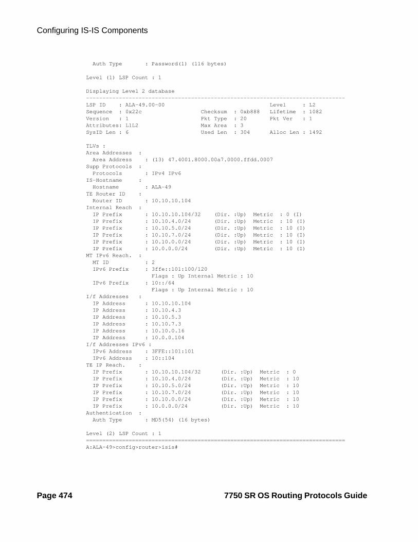
Configuring IS-IS Components
Auth Type : Password(1) (116 bytes)
Level (1) LSP Count : 1
Displaying Level 2 database-------------------------------------------------------------------------------LSP ID : ALA-49.00-00 Level : L2Sequence : 0x22c Checksum : 0xb888 Lifetime : 1082Version : 1 Pkt Type : 20 Pkt Ver : 1Attributes: L1L2 Max Area : 3SysID Len : 6 Used Len : 304 Alloc Len : 1492
TLVs :Area Addresses : Area Address : (13) 47.4001.8000.00a7.0000.ffdd.0007Supp Protocols : Protocols : IPv4 IPv6IS-Hostname : Hostname : ALA-49TE Router ID : Router ID : 10.10.10.104Internal Reach : IP Prefix : 10.10.10.104/32 (Dir. :Up) Metric : 0 (I) IP Prefix : 10.10.4.0/24 (Dir. :Up) Metric : 10 (I) IP Prefix : 10.10.5.0/24 (Dir. :Up) Metric : 10 (I) IP Prefix : 10.10.7.0/24 (Dir. :Up) Metric : 10 (I) IP Prefix : 10.10.0.0/24 (Dir. :Up) Metric : 10 (I) IP Prefix : 10.0.0.0/24 (Dir. :Up) Metric : 10 (I)MT IPv6 Reach. : MT ID : 2 IPv6 Prefix : 3ffe::101:100/120 Flags : Up Internal Metric : 10 IPv6 Prefix : 10::/64 Flags : Up Internal Metric : 10I/f Addresses : IP Address : 10.10.10.104 IP Address : 10.10.4.3 IP Address : 10.10.5.3 IP Address : 10.10.7.3 IP Address : 10.10.0.16 IP Address : 10.0.0.104I/f Addresses IPv6 : IPv6 Address : 3FFE::101:101 IPv6 Address : 10::104TE IP Reach. : IP Prefix : 10.10.10.104/32 (Dir. :Up) Metric : 0 IP Prefix : 10.10.4.0/24 (Dir. :Up) Metric : 10 IP Prefix : 10.10.5.0/24 (Dir. :Up) Metric : 10 IP Prefix : 10.10.7.0/24 (Dir. :Up) Metric : 10 IP Prefix : 10.10.0.0/24 (Dir. :Up) Metric : 10 IP Prefix : 10.0.0.0/24 (Dir. :Up) Metric : 10Authentication : Auth Type : MD5(54) (16 bytes)
Level (2) LSP Count : 1===============================================================================A:ALA-49>config>router>isis#
Page 474 7750 SR OS Routing Protocols Guide

IS-IS
Configure MT TLVs for IPv6 SPF:
CLI Syntax: config>router# isisipv6-routing mt
A:ALA-49>config>router>isis# info detail----------------------------------------------... ipv4-routing ipv6-routing mt multi-topology ipv6-unicast exit...----------------------------------------------A:ALA-49>config>router>isis#
Verify IPv6 routes:
CLI Syntax: show>router# isisroutes ipv6-unicast
A:ALA-49>config>router>isis# show router isis routes ipv6-unicast===============================================================================Route Table===============================================================================Prefix Metric Lvl/Typ Ver. SysID/Hostname NextHop MT-------------------------------------------------------------------------------No Matching Entries===============================================================================A:ALA-49>config>router>isis#
CLI Syntax: show>router# route-table ipv6
A:ALA-48>show>router# route-table ipv6===============================================================================IPv6 Route Table (Router: Base)===============================================================================Dest Prefix Type Proto Age Pref Next Hop[Interface Name] Metric-------------------------------------------------------------------------------10::/64 Local Local 05h35m28s 0 to-104 0-------------------------------------------------------------------------------No. of Routes: 1===============================================================================A:ALA-48>show>router#
7750 SR OS Routing Protocols Guide Page 475

Configuring IS-IS Components
Configuring Interface Parameters
There are no interfaces associated with IS-IS by default. An interface belongs to all areas configured on a router. Interfaces cannot belong to separate areas. There are no default interfaces applied to the router’s IS-IS instance. You must configure at least one IS-IS interface in order for IS-IS to work.
To enable IS-IS on an interface, first configure an IP interface in the config>router> interface context. Then, apply the interface in the config>router>isis>interface context.
You can configure both the Level 1 parameters and the Level 2 parameters on an interface. The level-capability value determines which level values are used.
NOTE: For point-to-point interfaces, only the values configured under Level 1 are used regardless of the operational level of the interface.
The following example displays the modified interface parameters:
Example: config>router# isisconfig>router>isis# level 1config>router>isis>level# wide-metrics-onlyconfig>router>isis>level# exitconfig>router>isis# level 2config>router>isis>level# wide-metrics-onlyconfig>router>isis>level# exitconfig>router>isis# interface ALA-1-2config>router>isis>if# level-capability level-2config>router>isis>if# mesh-group 85config>router>isis>if# exitconfig>router>isis# interface ALA-1-3config>router>isis>if# level-capability level-1config>router>isis>if# interface-type point-to-pointconfig>router>isis>if# mesh-group 101config>router>isis>if# exitconfig>router>isis# interface ALA-1-5config>router>isis>if# level-capability level-1config>router>isis>if# interface-type point-to-pointconfig>router>isis>if# mesh-group 85config>router>isis>if# exitconfig>router>isis# interface to-103config>router>isis>if# level-capability level-1/2>router>isis>if# mesh-group 101config>router>isis>if# exitconfig>router>isis#
Page 476 7750 SR OS Routing Protocols Guide

IS-IS
The following example displays the global and interface-level configurations.
A:ALA-A>config>router>isis# info---------------------------------------------- level-capability level-2 area-id 49.0180.0001 area-id 49.0180.0002 area-id 49.0180.0003 authentication-key "H5KBAWrAAQU" hash authentication-type password traffic-engineering level 1 wide-metrics-only exit level 2 wide-metrics-only exit interface "system" exit interface "ALA-1-2" level-capability level-2 mesh-group 85 exit interface "ALA-1-3" level-capability level-1 interface-type point-to-point mesh-group 101 exit interface "ALA-1-5" level-capability level-1 interface-type point-to-point mesh-group 85 exit interface "to-103" mesh-group 101 exit----------------------------------------------A:ALA-A>config>router>isis#
7750 SR OS Routing Protocols Guide Page 477

Configuring IS-IS Components
Figure 20: Configuring a Level 1 Area
The following example displays the command usage to configure a Level 1 area.
A:ALA-A>config>router# isisA:ALA-A>config>router>isis# area-id 47.0001A:ALA-A>config>router>isis# level-capability level-1A:ALA-A>config>router>isis# interface systemA:ALA-A>config>router>isis>if# exitA:ALA-A>config>router>isis# interface A-BA:ALA-A>config>router>isis>if# exitA:ALA-A>config>router>isis# interface A-CA:ALA-A>config>router>isis>if# exitA:ALA-A>config>router>isis#
A:ALA-B>config>router# isisA:ALA-B>config>router>isis# area-id 47.0001A:ALA-B>config>router>isis# level-capability level-1A:ALA-B>config>router>isis# interface systemA:ALA-B>config>router>isis>if# exitA:ALA-B>config>router>isis# interface B-AA:ALA-B>config>router>isis>if# exitA:ALA-B>config>router>isis# interface B-CA:ALA-B>config>router>isis>if# exitA:ALA-B>config>router>isis#
A:ALA-C>config>router# isis A:ALA-C>config>router>isis# area-id 47.0001A:ALA-C>config>router>isis# level-capability level-1A:ALA-C>config>router>isis# interface system
Example: Configuring a Level 1 Area
NOTE: Interfaces are configured in the config>router>interface context.
OSRG031
Area-ID 49.0180.0001
L1
Area-ID 49.0180.0001
L1
Area-ID 49.0180.0001
L1
Area A (ALA-A) Area B (ALA-B)
Area C (ALA-C)
Page 478 7750 SR OS Routing Protocols Guide

IS-IS
A:ALA-C>config>router>isis>if# exitA:ALA-C>config>router>isis# interface "C-A"A:ALA-C>config>router>isis>if# exitA:ALA-C>config>router>isis# interface "C-B"A:ALA-C>config>router>isis>if# exit
A:ALA-A>config>router>isis# info---------------------------------------------- level-capability level-1 area-id 49.0180.0001 interface "system" exit interface "A-B" exit interface "A-C" exit----------------------------------------------A:ALA-A>config>router>isis#
A:ALA-B>config>router>isis# info---------------------------------------------- level-capability level-1 area-id 49.0180.0001 interface "system" exit interface "B-A" exit interface "B-C" exit----------------------------------------------A:ALA-B>config>router>isis#
A:ALA-C>config>router>isis# info#------------------------------------------echo "ISIS"---------------------------------------------- level-capability level-1 area-id 49.0180.0001 interface "system" exit interface "C-A" exit interface "C-B" exit----------------------------------------------A:ALA-C>config>router>isis#
7750 SR OS Routing Protocols Guide Page 479

Configuring IS-IS Components
Figure 21: Configuring a Level 1/2 Area
The following example displays the command usage to configure a Level 1/2 system.
A:ALA-A>config>router# isisA:ALA-A>config>router>isis# level-capability level-1/2
Example: Modifying a Router’s Level Capability
In the previous example, ALA-A, ALA-B, and ALA-C are configured as Level 1 systems. Level 1 systems communicate with other Level 1 systems in the same area. In this example, ALA-A is modified to set the level capability to Level 1/2. Now, the Level 1 systems in the area with NET 47.0001 forward PDUs to ALA-A for destinations that are not in the local area.
OSRG036
Area-ID 49.0180.0001
L1
Area-ID 49.0180.0001
L1/2L2
L1/2Area-ID 49.0180.0001
L1
Area A (ALA-A) Area B (ALA-B)
Area C (ALA-C)
Page 480 7750 SR OS Routing Protocols Guide
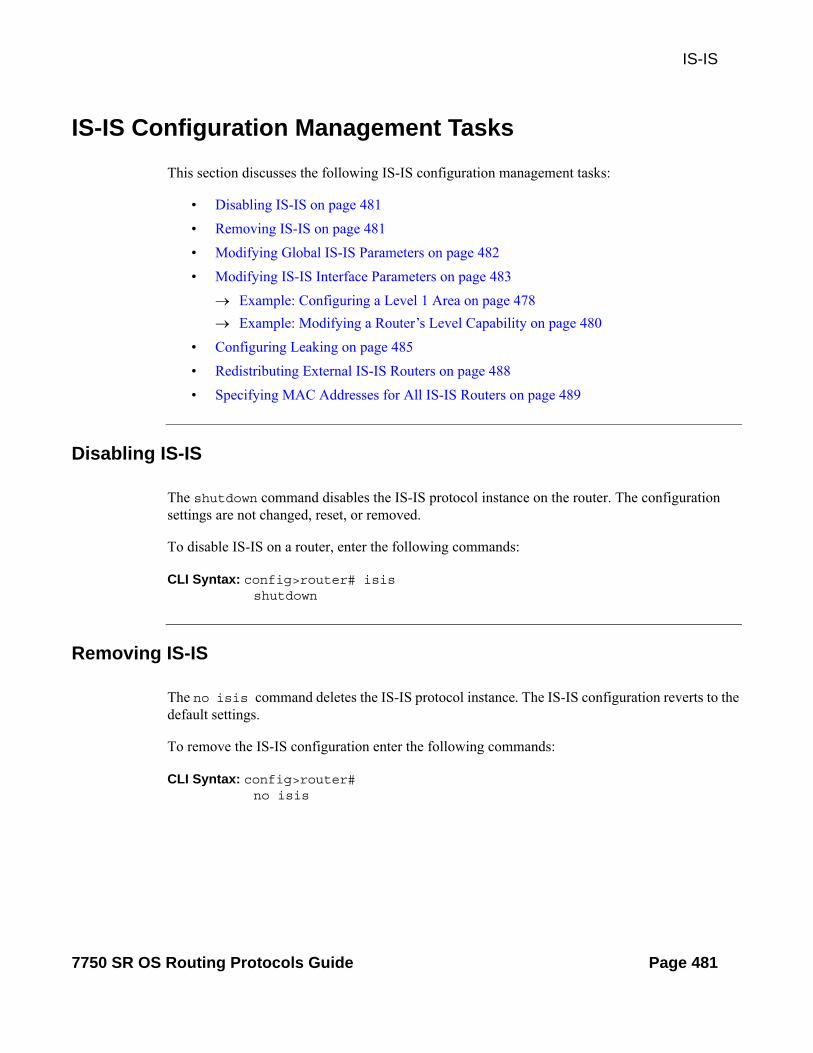
IS-IS
IS-IS Configuration Management Tasks
This section discusses the following IS-IS configuration management tasks:
• Disabling IS-IS on page 481
• Removing IS-IS on page 481
• Modifying Global IS-IS Parameters on page 482
• Modifying IS-IS Interface Parameters on page 483
Example: Configuring a Level 1 Area on page 478
Example: Modifying a Router’s Level Capability on page 480
• Configuring Leaking on page 485
• Redistributing External IS-IS Routers on page 488
• Specifying MAC Addresses for All IS-IS Routers on page 489
Disabling IS-IS
The shutdown command disables the IS-IS protocol instance on the router. The configuration settings are not changed, reset, or removed.
To disable IS-IS on a router, enter the following commands:
CLI Syntax: config>router# isisshutdown
Removing IS-IS
The no isis command deletes the IS-IS protocol instance. The IS-IS configuration reverts to the default settings.
To remove the IS-IS configuration enter the following commands:
CLI Syntax: config>router# no isis
7750 SR OS Routing Protocols Guide Page 481

IS-IS Configuration Management Tasks
Modifying Global IS-IS Parameters
You can modify, disable, or remove global IS-IS parameters without shutting down entities. Changes take effect immediately. Modifying the level capability on the global level causes the IS-IS protocol to restart. The following example displays command usage to modify various parameters:
Example: config>router>isis# overload timeout 500config>router>isis# level-capability level-1/2config>router>isis# no authentication-checkconfig>router>isis# authentication-key raiderslost
The following example displays the global modifications
A:ALA-A>config>router>isis# info---------------------------------------------- area-id 49.0180.0001 area-id 49.0180.0002 area-id 49.0180.0003 authentication-key "//oZrvtvFPn06S42lRIJsE" hash authentication-type password no authentication-check overload timeout 500 on-boot level 1 wide-metrics-only exit level 2 wide-metrics-only exit interface "system" exit interface "ALA-1-2" level-capability level-2 mesh-group 85 exit interface "ALA-1-3" level-capability level-1 interface-type point-to-point mesh-group 101 exit interface "ALA-1-5" level-capability level-1 interface-type point-to-point mesh-group 85 exit interface "to-103" mesh-group 101 exit interface "A-B" exit interface "A-C" exit----------------------------------------------A:ALA-A>config>router>isis#
Page 482 7750 SR OS Routing Protocols Guide

IS-IS
Modifying IS-IS Interface Parameters
You can modify, disable, or remove interface-level IS-IS parameters without shutting down entities. Changes take effect immediately. Modifying the level capability on the interface causes the IS-IS protocol on the interface to restart.
To remove an interface, issue the no interface ip-int-name command. To disable an interface, issue the shutdown command in the interface context.
The following example displays interface IS-IS modification command usage:
Example:config>router# isisconfig>router>isis# interface ALA-1-3config>router>isis>if# mesh-group 85config>router>isis>if# passiveconfig>router>isis>if# lsp-pacing-interval 5000config>router>isis>if# exitconfig>router>isis# interface to-103config>router>isis>if# hello-authentication-type message-digestconfig>router>isis>if# hello-authentication-key 49ersruleconfig>router>isis>if# exit
The following example displays the modified interface parameters.
A:ALA-A>config>router>isis# info---------------------------------------------- area-id 49.0180.0001 area-id 49.0180.0002 area-id 49.0180.0003 authentication-key "//oZrvtvFPn06S42lRIJsE" hash authentication-type password no authentication-check overload timeout 500 on-boot level 1 wide-metrics-only exit level 2 wide-metrics-only exit interface "system" exit interface "ALA-1-2" level-capability level-2 mesh-group 85 exit interface "ALA-1-3" level-capability level-1 interface-type point-to-point lsp-pacing-interval 5000 mesh-group 85 passive exit interface "ALA-1-5"
7750 SR OS Routing Protocols Guide Page 483

IS-IS Configuration Management Tasks
level-capability level-1 interface-type point-to-point mesh-group 85 exit interface "to-103" hello-authentication-key "DvR3l264KQ6vXMTvbAZ1mE" hash hello-authentication-type message-digest mesh-group 101 exit interface "A-B" exit----------------------------------------------A:ALA-A>config>router>isis#
Page 484 7750 SR OS Routing Protocols Guide

IS-IS
Configuring Leaking
IS-IS allows a two-level hierarchy to route PDUs. Level 1 areas can be interconnected by a contiguous Level 2 backbone.
The Level 1 link-state database contains information only about that area. The Level 2 link-state database contains information about the Level 2 system and each of the Level 1 systems in the area. A Level 1/2 router contains information about both Level 1 and Level 2 databases. A Level 1/2 router advertises information about its Level 1 area toward the other Level 1/2 or Level 2 (only) routers.
Packets with destinations outside the Level 1 area are forwarded toward the closest Level 1/2 router which, in turn, forwards the packets to the destination area.
Sometimes, the shortest path to an outside destination is not through the closest Level 1/2 router, or, the only Level 1/2 system to forward packets out of an area is not operational. Route leaking provides a mechanism to leak Level 2 information to Level 1 systems to provide routing information regarding inter-area routes. Then, a Level 1 router has more options to forward packets.
Configure a route policy to leak routers from Level 2 into Level 1 areas in the config>router>policy-options>policy-statement context.
The following example shows the command usage to configure prefix list and policy statement parameters in the config>router context.
config>router>policy-options# prefix-list loops..>policy-options>prefix-list# prefix 10.1.1.0/24 longer..>policy-options>prefix-list# exit..>policy-options# policy-statement leak..>policy-options>policy-statement# entry 10..>policy-options>policy-statement>entry# from..>policy-options>policy-statement>entry>from# prefix-list loops..>policy-options>policy-statement>entry>from# level 2..>policy-options>policy-statement>entry>from# exit..>policy-options>policy-statement>entry# to..>policy-options>policy-statement>entry>to# level 1..>policy-options>policy-statement>entry>to# exit..>policy-options>policy-statement>entry# action accept..>policy-options>policy-statement>entry>action# exit..>policy-options>policy-statement>entry# exit..>policy-options>policy-statement#exit..>policy-options# commit ..>policy-options#
7750 SR OS Routing Protocols Guide Page 485

IS-IS Configuration Management Tasks
A:ALA-A>config>router>policy-options# info---------------------------------------------- prefix-list "loops" prefix 10.1.1.0/24 longer exit policy-statement "leak" entry 10 from prefix-list "loop" level 2 exit to level 1 exit action accept exit exit exit----------------------------------------------A:ALA-A>config>router>policy-options#
Next, apply the policy to leak routes from Level 2 info Level 1 systems on ALA-A.
config>router#isisconfig>router>isis# export leak
A:ALA-A>config>router>isis# info---------------------------------------------- area-id 49.0180.0001 area-id 49.0180.0002 area-id 49.0180.0003 authentication-key "//oZrvtvFPn06S42lRIJsE" hash authentication-type password no authentication-check export "leak"...----------------------------------------------A:ALA-A>config>router>isis#
Page 486 7750 SR OS Routing Protocols Guide

IS-IS
After the policy is applied, create a policy to redistribute external IS-IS routes from Level 1 systems into the Level 2 backbone (see Redistributing External IS-IS Routers on page 488). In the config>router context, configure the following policy statement parameters:
config>router>policy-options# begin..>policy-options# policy-statement "isis-ext"..>policy-options>policy-statement# entry 10..>policy-options>policy-statement>entry$ from..>policy-options>policy-statement>entry>from$ external..>policy-options>policy-statement>entry>from# exit..>policy-options>policy-statement>entry# to..>policy-options>policy-statement>entry>to$ level 2..>policy-options>policy-statement>entry>to# exit..>policy-options>policy-statement>entry# action accept..>policy-options>policy-statement>entry>action# exit..>policy-options>policy-statement>entry# exit..>policy-options>policy-statement# exit..>policy-options# commit
A:ALA-A>config>router>policy-options# info---------------------------------------------- prefix-list "loops" prefix 10.1.1.0/24 longer exit policy-statement "leak" entry 10 from prefix-list "loop" level 2 exit to level 1 exit action accept exit exit exit policy-statement "isis-ext" entry 10 from external exit to level 2 exit action accept exit exit exit----------------------------------------------A:ALA-A>config>router>policy-options#
7750 SR OS Routing Protocols Guide Page 487

IS-IS Configuration Management Tasks
Redistributing External IS-IS Routers
IS-IS does not redistribute Level 1 external routes into Level 2 by default. You must explicitly apply the policy to redistribute external IS-IS routes. Policies are created in the config>router>policy-options context. Refer to the Route Policy section of this manual for more information.
The following example displays the policy statement configuration.
config>router>policy-options# info---------------------------------------------- prefix-list "loops" prefix 10.1.1.0/24 longer exit policy-statement "leak" entry 10 from prefix-list "loop" level 2 exit to level 1 exit action accept exit exit exit policy-statement "isis-ext" entry 10 from external exit to level 2 exit action accept exit exit exit----------------------------------------------config>router>policy-options#
Page 488 7750 SR OS Routing Protocols Guide

IS-IS
Specifying MAC Addresses for All IS-IS Routers
Specify the MAC address to use for all L1 or L2 IS-IS routers. The following example shows how to specify all L1 routers:
Example: all-l1isis 01-80-C2-00-00-14
You can also specify the MAC address for all L2 IS-IS routers by using the all-l2isis command.
7750 SR OS Routing Protocols Guide Page 489
IS-IS Configuration Management Tasks
Page 490 7750 SR OS Routing Protocols Guide

IS-IS
IS-IS Configuration Commands
Generic Commands
isis
Syntax isis [instance-id]no isis [instance-id]
Context config>router
Description This command creates the context to configure the Intermediate-System-to-Intermediate-System (IS-IS) protocol instance.
The IS-IS protocol instance is enabled with the no shutdown command in the config>router>isis context. Alternatively, the IS-IS protocol instance is disabled with the shutdown command in the config>router>isis context.
The no form of the command deletes the IS-IS protocol instance. Deleting the protocol instance removes all configuration parameters for this IS-IS instance.
Parameters instance-id — Specifies the instance ID for an IS-IS instance.
Values 1–31
Default 0
shutdown
Syntax [no] shutdown
Context config>router>isisconfig>router>isis>interface ip-int-nameconfig>router>isis>if>level level-number
Description This command administratively disables an entity. When disabled, an entity does not change, reset, or remove any configuration settings or statistics.
The operational state of the entity is disabled as well as the operational state of any entities contained within. Many objects must be shut down before they may be deleted.
The no form of this command administratively enables an entity.
Special Cases IS-IS Global — In the config>router>isis context, the shutdown command disables the IS-IS protocol instance. By default, the protocol is enabled, no shutdown.
IS-IS Interface — In the config>router>isis>interface context, the command disables the IS-IS interface. By default, the IS-IS interface is enabled, no shutdown.
7750 SR OS Routing Protocols Guide Page 491

Generic Commands
IS-IS Interface and Level — In the config>router>isis>interface ip-int-name>level context, the com-mand disables the IS-IS interface for the level. By default, the IS-IS interface at the level is enabled, no shut-down.
Default no shutdown — IS-IS entity is administratively enabled.
tag
Syntax tag tagno tag
Context config>router>isis>interface
Description This command configures a route tag to the specified IP address of an interface.
Parameters tag — [1..4294967295]
all-l1isis
Syntax all-l1isis ieee-addressno all-l1isis
Context config>router>isis
Description This command enables you to specify the MAC address to use for all L1 IS-IS routers. The MAC address should be a multicast address. You should shut/no shut the IS-IS instance to make the change operational.
Default all-l1isis 01-80-C2-00-01-00
Parameters ieee-address — Specifies the destination MAC address for all L1 I-IS neighbors on the link for this ISIS instance.
all-l2isis
Syntax all-l2isis ieee-addressno all-l2isis
Context config>router>isis
Description This command enables you to specify the MAC address to use for all L2 IS-IS routers. The MAC address should be a multicast address. You should shut/no shut the IS-IS instance to make the change operational.
Default all-l2isis 01-80-C2-00-02-11
Parameters ieee-address — Specifies the destination MAC address for all L2 ISIS neighbors on the link for this ISIS instance.
Page 492 7750 SR OS Routing Protocols Guide

IS-IS
authentication-check
Syntax [no] authentication-check
Context config>router>isis
Description This command sets an authentication check to reject PDUs that do not match the type or key requirements.
The default behavior when authentication is configured is to reject all IS-IS protocol PDUs that have a mis-match in either the authentication type or authentication key.
When no authentication-check is configured, authentication PDUs are generated and IS-IS PDUs are authenticated on receipt. However, mismatches cause an event to be generated and will not be rejected.
The no form of this command allows authentication mismatches to be accepted and generate a log event.
Default authentication-check — Rejects authentication mismatches.
authentication-key
Syntax authentication-key [authentication-key | hash-key] [hash | hash2]no authentication-key
Context config>router>isisconfig>router>isis>level level-number
Description This command sets the authentication key used to verify PDUs sent by neighboring routers on the interface.
Neighboring routers use passwords to authenticate PDUs sent from an interface. For authentication to work, both the authentication key and the authentication type on a segment must match. The authentication-type statement must also be included.
To configure authentication on the global level, configure this command in the config>router>isis context. When this parameter is configured on the global level, all PDUs are authenticated including the hello PDU.
To override the global setting for a specific level, configure the authentication-key command in the con-fig>router>isis>level context. When configured within the specific level, hello PDUs are not authenticated.
The no form of the command removes the authentication key.
Default no authentication-key — No authentication key is configured.
Parameters authentication-key — The authentication key. The key can be any combination of ASCII characters up to 255 characters in length (un-encrypted). If spaces are used in the string, enclose the entire string in quo-tation marks (“ ”).
hash-key — The hash key. The key can be any combination of ASCII characters up to 342 characters in length (encrypted). If spaces are used in the string, enclose the entire string in quotation marks (“ ”).
This is useful when a user must configure the parameter, but, for security purposes, the actual unencrypted key value is not provided.
hash — Specifies the key is entered in an encrypted form. If the hash parameter is not used, the key is assumed to be in a non-encrypted, clear text form. For security, all keys are stored in encrypted form in the configuration file with the hash parameter specified.
7750 SR OS Routing Protocols Guide Page 493

Generic Commands
hash2 — Specifies the key is entered in a more complex encrypted form. If the hash2 parameter is not used, the less encrypted hash form is assumed.
authentication-type
Syntax authentication-type {password | message-digest}no authentication
Context config>router>isisconfig>router>isis>level level-number
Description This command enables either simple password or message digest authentication or must go in either the global IS-IS or IS-IS level context.
Both the authentication key and the authentication type on a segment must match. The authentication-key statement must also be included.
Configure the authentication type on the global level in the config>router>isis context.
Configure or override the global setting by configuring the authentication type in the con-fig>router>isis>level context.
The no form of the command disables authentication.
Default no authentication-type — No authentication type is configured and authentication is disabled.
Parameters password — Specifies that simple password (plain text) authentication is required.
message-digest — Specifies that MD5 authentication in accordance with RFC2104 is required.
bfd-enable
Syntax [no] bfd-enable {ipv4 | ipv6}
Context config>router>isis>interface
Description This command enables the use of bi-directional forwarding (BFD) to control IPv4 adjacencies. By enabling BFD on an IPv4 or IPv6 protocol interface, the state of the protocol interface is tied to the state of the BFD session between the local node and the remote node. The parameters used for the BFD are set by the BFD command under the IP interface. This command must be given separately to enable/disable BFD for both IPv4 and IPv6.
The no form of this command removes BFD from the associated adjacency.
Default no bfd-enable ipv4
Page 494 7750 SR OS Routing Protocols Guide

IS-IS
default-route-tag
Syntax default-route-tag tagno default-route-tag
Context config>router>isis
Description This command configures the route tag for default route.
Parameters tag — tag — Assigns a default tag
Values Accepts decimal or hex formats: ISIS: [0x0..0xFFFFFFFF]H
Values 1 — 4294967295
csnp-authentication
Syntax [no] csnp-authentication
Context config>router>isisconfig>router>isis>level level-number
Description This command enables authentication of individual ISIS packets of complete sequence number PDUs (CSNP) type.
The no form of the command suppresses authentication of CSNP packets.
csnp-interval
Syntax csnp-interval secondsno csnp-interval
Context config>router>isis>interface ip-int-name
Description This command configures the time interval, in seconds, to send complete sequence number (CSN) PDUs from the interface. IS-IS must send CSN PDUs periodically.
The no form of the command reverts to the default value.
Default csnp-interval 10 — CSN PDUs are sent every 10 seconds for LAN interfaces.
csnp-interval 5 — CSN PDUs are sent every 5 seconds for point-to-point interfaces.
Parameters seconds — The time interval, in seconds between successive CSN PDUs sent from this interface expressed as a decimal integer.
Values 1 — 65535
7750 SR OS Routing Protocols Guide Page 495

Generic Commands
default-metric
Syntax default-metric ipv4 metricno default-metric
Context config>router>isis>level
Description This command specifies the configurable default metric used for all IS-IS interfaces on this level. This value is not used if a metric is configured for an interface.
Default 10
ipv4 metric — Specifies the default metric for IPv4 unicast.
Values 1 — 16777215
disable-ldp-sync
Syntax [no] disable-ldp-sync
Context config>router>isis
Description This command disables the IGP-LDP synchronization feature on all interfaces participating in the OSPF or IS-IS routing protocol. When this command is executed, IGP immediately advertises the actual value of the link cost for all interfaces which have the IGP-LDP synchronization enabled if the currently advertized cost is different. It will then disable IGP-LDP synchornization for all interfaces. This command does not delete the interface configuration. The no form of this command has to be entered to re-enable IGP-LDP synchronization for this routing protocol.
The no form of this command restores the default settings and re-enables IGP-LDP synchronization on all interfaces participating in the OSPF or IS-IS routing protocol and for which the ldp-sync-timer is configured.
Default no disable-ldp-sync
export
Syntax [no] export policy-name [policy-name...up to 5 max]
Context config>router>isis
Description This command configures export routing policies that determine the routes exported from the routing table to IS-IS.
If no export policy is defined, non IS-IS routes are not exported from the routing table manager to IS-IS.
If multiple policy names are specified, the policies are evaluated in the order they are specified. The first pol-icy that matches is applied. If multiple export commands are issued, the last command entered overrides the previous command. A maximum of five policy names can be specified.
Page 496 7750 SR OS Routing Protocols Guide

IS-IS
If an aggregate command is also configured in the config>router context, then the aggregation is applied before the export policy is applied.
Routing policies are created in the config>router>policy-options context.
The no form of the command removes the specified policy-name or all policies from the configuration if no policy-name is specified.
Default no export — No export policy name is specified.
Parameters policy-name — The export policy name. Up to five policy-name arguments can be specified.
export-limit
Syntax export-limit number [log percentage]no export-limit
Context config>router>isis
Description This command configures the maximum number of routes (prefixes) that can be exported into IS-IS from the route table.
The no form of the command removes the parameters from the configuration.
Default no export-limit, the export limit for routes or prefixes is disabled..
Parameters number — Specifies the maximum number of routes (prefixes) that can be exported into RIP from the route table.
Values 1 — 4294967295
log percentage — Specifies the percentage of the export-limit, at which a warning log message and SNMP notification would be sent.
Values 1 — 100
external-preference
Syntax external-preference preferenceno external-preference
Context config>router>isis>level level-number
Description This command configures the external route preference for the IS-IS level.
The external-preference command configures the preference level of either IS-IS level 1 or IS-IS level 2 external routes. By default, the preferences are as listed in the table below.
A route can be learned by the router by different protocols, in which case, the costs are not comparable. When this occurs, the preference decides the route to use.
Different protocols should not be configured with the same preference, if this occurs the tiebreaker is depen-dent on the default preference table. If multiple routes are learned with an identical preference using the
7750 SR OS Routing Protocols Guide Page 497

Generic Commands
same protocol, the lowest cost route is used. If multiple routes are learned with an identical preference using the same protocol and the costs (metrics) are equal, then the decision of the route to use is determined by the configuration of the ecmp in the config>router context.
Default Default preferences are listed in the following table:
Route Type Preference Configurable
Direct attached 0 No
Static-route 5 Yes
OSPF internal routes 10 No
IS-IS Level 1 internal 15 Yes*
*. Internal preferences are changed using the preference command in the config>router>isis>level level-number context
IS-IS Level 2 internal 18 Yes*
OSPF external 150 Yes
IS-IS Level 1 external 160 Yes
IS-IS Level 2 external 165 Yes
BGP 170 Yes
Parameters preference — The preference for external routes at this level as expressed.
Values 1 — 255
graceful-restart
Syntax [no] graceful-restart
Context config>router>isis
Description This command enables graceful-restart helper support for ISIS. The 7750 SR OS will act as a helper to neighbors who are graceful-restart-capable and are restarting.
When the control plane of a graceful-restart-capable router fails, the neighboring routers (graceful-restart helpers) temporarily preserve adjacency information so packets continue to be forwarded through the failed graceful-restart router using the last known routes. If the control plane of the graceful-restart router comes back up within the timer limits, then the routing protocols re-converge to minimize service interruption.
The no form of the command disables graceful restart and removes all graceful restart configurations in the ISIS instance.
Default disabled
Page 498 7750 SR OS Routing Protocols Guide

IS-IS
helper-disable
Syntax [no] helper-disable
Context config>router>isis>graceful-restart
Description This command disables the helper support for graceful restart.
When graceful-restart is enabled, the router can be a helper (meaning that the router is helping a neighbor to restart) or be a restarting router or both. The 7750 SR OS supports only helper mode. This facilitates the graceful restart of neighbors but will not act as a restarting router (meaning that the 7750 SR OS will not help the neighbors to restart).
The no helper-disable command enables helper support and is the default when graceful-restart is enabled.
Default disabled
hello-authentication
Syntax [no] hello-authentication
Context config>router>isisconfig>router>isis>level level-number
Description This command enables authentication of individual ISIS packets of HELLO type.
The no form of the command suppresses authentication of HELLO packets.
loopfree-alternate-exclude
Syntax [no] loopfree-alternate
Context configure>router>isis>levelconfigure>router>isis>interface
Description This command instructs IGP to not include a specific interface or all interfaces participating in a specific IS-IS level or OSPF area in the SPF LFA computation. This provides a way of reducing the LFA SPF calcula-tion where it is not needed.
When an interface is excluded from the LFA SPF in IS-IS, it is excluded in both level 1 and level 2. When it is excluded from the LFA SPF in OSPF, it is excluded in all areas. However, the above OSPF command can only be executed under the area in which the specified interface is primary and once enabled, the interface is excluded in that area and in all other areas where the interface is secondary. If the user attempts to apply it to an area where the interface is secondary, the command will fail.
The no form of this command re-instates the default value for this command.
Default no loopfree-alternate-exclude
7750 SR OS Routing Protocols Guide Page 499

Generic Commands
loopfree-alternate
Syntax [no] loopfree-alternate
Context config>router>isis
Description This command enables Loop-Free Alternate (LFA) computation by SPF under the IS-IS routing protocol level or under the OSPF routing protocol instance level.
When this command is enabled, it instructs the IGP SPF to attempt to pre-compute both a primary next-hop and an LFA next-hop for every learned prefix. When found, the LFA next-hop is populated into the routing table along with the primary next-hop for the prefix.
The no form of this command disables the LFA computation by IGP SPF.
Default no loopfree-alternate
hello-authentication-key
Syntax hello-authentication-key [authentication-key | hash-key] [hash | hash2]no hello-authentication-key
Context config>router>isis>interface ip-int-nameconfig>router>isis>if>level level-number
Description This command configures the authentication key (password) for hello PDUs. Neighboring routers use the password to verify the authenticity of hello PDUs sent from this interface. Both the hello authentication key and the hello authentication type on a segment must match. The hello-authentication-type must be speci-fied.
To configure the hello authentication key in the interface context use the hello-authentication-key in the config>router>isis>interface context.
To configure or override the hello authentication key for a specific level, configure the hello-authentica-tion-key in the config>router>isis>interface>level context.
If both IS-IS and hello-authentication are configured, hello messages are validated using hello authentica-tion. If only IS-IS authentication is configured, it will be used to authenticate all IS-IS (including hello) pro-tocol PDUs.
When the hello authentication key is configured in the config>router>isis>interface context, it applies to all levels configured for the interface.
The no form of the command removes the authentication-key from the configuration.
Default no hello-authentication-key — No hello authentication key is configured.
Parameters authentication-key — The hello authentication key (password). The key can be any combination of ASCII characters up to 254 characters in length (un-encrypted). If spaces are used in the string, enclose the entire string in quotation marks (“ ”).
hash-key — The hash key. The key can be any combination of ASCII characters up to 342 characters in length (encrypted). If spaces are used in the string, enclose the entire string in quotation marks (“ ”).
Page 500 7750 SR OS Routing Protocols Guide

IS-IS
This is useful when a user must configure the parameter, but, for security purposes, the actual unencrypted key value is not provided.
hash — Specifies the key is entered in an encrypted form. If the hash parameter is not used, the key is assumed to be in a non-encrypted, clear text form. For security, all keys are stored in encrypted form in the configuration file with the hash parameter specified.
hash2 — Specifies the key is entered in a more complex encrypted form. If the hash2 parameter is not used, the less encrypted hash form is assumed.
hello-authentication-type
Syntax hello-authentication-type {password | message-digest}no hello-authentication-type
Context config>router>isis>interface ip-int-nameconfig>router>isis>if>level level-number
Description This command enables hello authentication at either the interface or level context. Both the hello authentica-tion key and the hello authentication type on a segment must match. The hello authentication-key statement must also be included.
To configure the hello authentication type at the interface context, use hello-authentication-type in the con-fig>router>isis>interface context.
To configure or override the hello authentication setting for a given level, configure the hello-authentica-tion-type in the config>router>isis>interface>level context.
The no form of the command disables hello authentication.
Default no hello-authentication-type — Hello authentication is disabled.
Parameters password — Specifies simple password (plain text) authentication is required.
message-digest — Specifies MD5 authentication in accordance with RFC2104 (HMAC: Keyed-Hashing
for Message Authentication) is required.
hello-interval
Syntax hello-interval secondsno hello-interval
Context config>router>isis>if>level level-number
Description This command configures the interval in seconds between hello messages issued on this interface at this level.
The no form of the command to reverts to the default value.
Default 3 — Hello interval default for the designated intersystem.
7750 SR OS Routing Protocols Guide Page 501

Generic Commands
9 — Hello interval default for non-designated intersystems.
Parameters seconds — The hello interval in seconds expressed as a decimal integer.
Values 1 — 20000
hello-multiplier
Syntax hello-multiplier multiplierno hello-multiplier
Context config>router>isis>if>level level-number
Description This command configures the number of missing hello PDUs from a neighbor after the router declares the adjacency down.
The no form of the command reverts to the default value.
Default 3 — The router can miss up to 3 hello messages before declaring the adjacency down.
Parameters multiplier — The multiplier for the hello interval expressed as a decimal integer.
Values 2 — 100
ipv6-unicast-metric
Syntax ipv6-unicast-metric metricno ipv6-unicast-metric
Context config>router>isis>if>level
Description This command configures IS-IS interface metric for IPv6 unicast.
The no form of this command removes the metric from the configuration.
Parameters metric — Specifies the IS-IS interface metric for IPv6 unicast.
Values 1 — 16777215
interface
Syntax [no] interface ip-int-name
Context config>router>isis
Description This command creates the context to configure an IS-IS interface.
When an area is defined, the interfaces belong to that area. Interfaces cannot belong to separate areas.
When the interface is a POS channel, the OSINCP is enabled when the interface is created and removed when the interface is deleted.
Page 502 7750 SR OS Routing Protocols Guide

IS-IS
The no form of the command removes IS-IS from the interface.
The shutdown command in the config>router>isis>interface context administratively disables IS-IS on the interface without affecting the IS-IS configuration.
Default no interface — No IS-IS interfaces are defined.
Parameters ip-int-name — Identify the IP interface name created in the config>router>interface context. The IP inter-face name must already exist.
interface-type
Syntax interface-type {broadcast | point-to-point}no interface-type
Context config>router>isis>interface ip-int-name
Description This command configures the IS-IS interface type as either broadcast or point-to-point.
Use this command to set the interface type of an Ethernet link to point-to-point to avoid having to carry the designated IS-IS overhead if the link is used as a point-to-point.
If the interface type is not known at the time the interface is added to IS-IS and subsequently the IP interface is bound (or moved) to a different interface type, then this command must be entered manually.
The no form of the command reverts to the default value.
Special Cases SONET — Interfaces on SONET channels default to the point-to-point type.
Ethernet or Unknown — Physical interfaces that are Ethernet or unknown default to the broadcast type.
Default point-to-point — For IP interfaces on SONET channels.
broadcast — For IP interfaces on Ethernet or unknown type physical interfaces.
Parameters broadcast — Configures the interface to maintain this link as a broadcast network.
point-to-point — Configures the interface to maintain this link as a point-to-point link.
ipv4-routing
Syntax [no] ipv4-routing
Context config>router>isis
Description This command specifies whether this IS-IS instance supports IPv4.
The no form of the command disables IPv4 on the IS-IS instance.
Default ipv4-routing
7750 SR OS Routing Protocols Guide Page 503

Generic Commands
ipv6-routing
Syntax [no] ipv6-routing {native | mt}
Context config>router>isis
Description This command enables IPv6 routing.
The no form of the command disables support for IS-IS IPv6 TLVs for IPv6 routing.
Default disabled
Parameters native — Enables IS-IS IPv6 TLVs for IPv6 routing and enables support for native IPv6 TLVs.
mt — Enables IS-IS multi-topology TLVs for IPv6 routing. When this parameter is specified, the support for native IPv6 TLVs is disabled.
ldp-over-rsvp
Syntax [no] ldp-over-rsvp
Context config>router>isis
Description This command allows LDP over RSVP processing in IS-IS.
The no form of the command disables LDP over RSVP processing.
Default no ldp-over-rsvp
iid-tlv-enable
Syntax [no] iid-tlv-enable
Context config>router>isis
Description This command specifies whether Instance Identifier (IID) TLV has been enabled or disabled for this ISIS instance.
When enabled, each I-IS instance marks its packets with the IID TLV containing its unique 16-bit IID for the routing domain. You should shut/no shut the isis instance to make the change operational.
Default no iid-tlv-enable
Page 504 7750 SR OS Routing Protocols Guide

IS-IS
level
Syntax level level-number
Context config>router>isisconfig>router>isis>interface ip-int-name
Description This command creates the context to configure IS-IS Level 1 or Level 2 area attributes.
A router can be configured as a Level 1, Level 2, or Level 1-2 system. A Level 1 adjacency can be estab-lished if there is at least one area address shared by this router and a neighbor. A Level 2 adjacency cannot be established over this interface.
Level 1/2 adjacency is created if the neighbor is also configured as Level 1/2 router and has at least one area address in common. A Level 2 adjacency is established if there are no common area IDs.
A Level 2 adjacency is established if another router is configured as Level 2 or a Level 1/2 router with inter-faces configured as Level 1/2 or Level 2. Level 1 adjacencies will not established over this interface.
To reset global and/or interface level parameters to the default, the following commands must be entered independently:
level> no hello-authentication-keylevel> no hello-authentication-typelevel> no hello-intervallevel> no hello-multiplier level> no metriclevel> no passivelevel> no priority
Special Cases Global IS-IS Level — The config>router>isis context configures default global parameters for both Level 1 and Level 2 interfaces.
IS-IS Interface Level — The config>router>isis>interface context configures IS-IS operational charac-teristics of the interface at Level 1 and/or Level 2. A logical interface can be configured on one Level 1 and one Level 2. In this case, each level can be configured independently and parameters must be removed inde-pendently.
By default an interface operates in both Level 1 and Level 2 modes.
Default level 1 or level 2
Parameters level-number — The IS-IS level number.
Values 1, 2
7750 SR OS Routing Protocols Guide Page 505

Generic Commands
level-capability
Syntax level-capability {level-1 | level-2 | level-1/2}no level-capability
Context config>router>isisconfig>router>isis>interface ip-int-name
Description This command configures the routing level for an instance of the IS-IS routing process.
An IS-IS router and an IS-IS interface can operate at Level 1, Level 2 or both Level 1 and 2.
Table 13 displays configuration combinations and the potential adjacencies that can be formed.
Table 13: Potential Adjacency Capabilities
Global Level Interface Level Potential Adjacency
L 1/2 L 1/2 Level 1 and/or Level 2
L 1/2 L 1 Level 1 only
L 1/2 L 2 Level 2 only
L 2 L 1/2 Level 2 only
L 2 L 2 Level 2 only
L 2 L 1 none
L 1 L 1/2 Level 1 only
L 1 L 2 none
L 1 L 1 Level 1 only
The no form of the command removes the level capability from the configuration.
Special Cases IS-IS Router — In the config>router>isis context, changing the level-capability performs a restart on the IS-IS protocol instance.
IS-IS Interface — In the config>router>isis>interface context, changing the level-capability performs a restart of IS-IS on the interface.
Default level-1/2
Parameters level-1 — Specifies the router/interface can operate at Level 1only.
level-2 — Specifies the router/interface can operate at Level 2 only.
level-1/2 — Specifies the router/interface can operate at both Level 1 and Level 2.
Page 506 7750 SR OS Routing Protocols Guide

IS-IS
lsp-pacing-interval
Syntax lsp-pacing-interval millisecondsno lsp-pacing-interval
Context config>router>isis>interface ip-int-name
Description This command configures the interval between LSP PDUs sent from this interface.
To avoid bombarding adjacent neighbors with excessive data, pace the Link State Protocol Data Units (LSP’s). If a value of zero is configured, no LSP’s are sent from the interface.
The no form of the command reverts to the default value.
Default 100 — LSPs are sent in 100 millisecond intervals.
Parameters milliseconds — The interval in milliseconds that IS-IS LSP’s can be sent from the interface expressed as a decimal integer.
Values 0 — 65535
lsp-lifetime
Syntax lsp-lifetime secondsno lsp-lifetime
Context config>router>isis
Description This command sets the time, in seconds, the router wants the LSPs it originates to be considered valid by other routers in the domain.
Each LSP received is maintained in an LSP database until the lsp-lifetime expires unless the originating router refreshes the LSP. By default, each router refreshes its LSP’s every 20 minutes (1200 seconds) so other routers will not age out the LSP.
The LSP refresh timer is derived from this formula: lsp-lifetime/2
The no form of the command reverts to the default value.
Default 1200 — LSPs originated by the router should be valid for 1200 seconds (20 minutes).
Parameters seconds — The time, in seconds, that the router wants the LSPs it originates to be considered valid by other routers in the domain.
Values 350 — 65535
7750 SR OS Routing Protocols Guide Page 507

Generic Commands
lsp-mtu-size
Syntax lsp-mtu-size size no lsp-mtu-size
Context config>router>isis
Description This command configures the LSP MTU size. If the size value is changed from the default using CLI or SNMP, then ISIS must be restarted in order for the change to take effect. This can be done by performing a shutdown command and then a no shutdown command in the config>router>isis context. Note: Using the exec command to execute a configuration file to change the LSP MTU-size from its default value will auto-matically bounce IS-IS for the change to take effect.
The no form of the command reverts to the default value.
Default 1492
Parameters size — Specifies the LSP MTU size.
Values 490 — 9190
lsp-wait
Syntax lsp-wait lsp-wait [lsp-initial-wait [lsp-second-wait]]
Context config>router>isis
Description This command is used to customize the throttling of IS-IS LSP-generation. Timers that determine when to generate the first, second and subsequent LSPs can be controlled with this command. Subsequent LSPs are generated at increasing intervals of the second lsp-wait timer until a maximum value is reached.
Parameters lsp-max-wait — Specifies the maximum interval in seconds between two consecutive ocurrences of an LSP being generated.
Values 1 — 120
Default 5
lsp-initial-wait — Specifies the initial LSP generation delay in seconds.
Values 0 — 100
Default 0
lsp-second-wait — Specifies the hold time in seconds between the first and second LSP generation.
Values 1 — 100
Default 1
Page 508 7750 SR OS Routing Protocols Guide

IS-IS
mcast-import-ipv6
Syntax [no] mcast-import-ipv6
Context configure>router>isis
Description This command administratively enables/disables submission of routes into the IPv6 multicast RTM by IS-IS.
multi-topology
Syntax [no] multi-topology
Context config>router>isis
Description This command enables IS-IS multi-topology support.
Default disabled
ipv6-unicast
Syntax [no] ipv6-unicast
Context config>router>isis>multi-topology
Description This command enables multi-topology TLVs.
The no form of the command disables multi-topology TLVs.
multicast-import
Syntax [no] multicast-import
Context config>router>isis
Description This command enables the submission of routes into the multicast Route Table Manager (RTM) by IS-IS.
The no form of the command disables the submission of routes into the multicast RTM.
Default no multicast-import
7750 SR OS Routing Protocols Guide Page 509

Generic Commands
mesh-group
Syntax mesh-group {value | blocked}no mesh-group
Context config>router>isis>interface ip-int-name
Description This command assigns an interface to a mesh group. Mesh groups limit the amount of flooding that occurs when a new or changed LSP is advertised throughout an area.
All routers in a mesh group should be fully meshed. When LSPs need to be flooded, only a single copy is received rather than a copy per neighbor.
To create a mesh group, configure the same mesh group value for each interface that is part of the mesh group. All routers must have the same mesh group value configured for all interfaces that are part of the mesh group.
To prevent an interface from flooding LSPs, the optional blocked parameter can be specified. Configure mesh groups carefully. It is easy to created isolated islands that do not receive updates as (other) links fail.
The no form of the command removes the interface from the mesh group.
Default no mesh-group — The interface does not belong to a mesh group.
Parameters value — The unique decimal integer value distinguishes this mesh group from other mesh groups on this or any other router that is part of this mesh group.
Values 1 — 2000000000
blocked — Prevents an interface from flooding LSPs.
ipv6-unicast-disable
Syntax [no] ipv6-unicast-disable
Context config>router>isis>if
Description This command disables IS-IS IPv6 unicast routing for the interface.
By default IPv6 unicast on all interfaces is enabled. However, IPv6 unicast routing on IS-IS is in effect when the config>router>isis>ipv6-routing mt command is configured.
The no form of the command enables IS-IS IPv6 unicast routing for the interface.
metric
Syntax metric metricno metric
Context config>router>isis>if>level level-number
Description This command configures the metric used for the level on the interface.
Page 510 7750 SR OS Routing Protocols Guide

IS-IS
In order to calculate the lowest cost to reach a given destination, each configured level on each interface must have a cost. The costs for each level on an interface may be different.
If the metric is not configured, the default of 10 is used unless reference bandwidth is configured.
The no form of the command reverts to the default value.
Default 10 — A metric of 10 for the level on the interface is used.
Parameters metric — The metric assigned for this level on this interface.
Values 1 — 16777215
advertise-passive-only
Syntax [no] advertise-passive-only
Context config>router>isis
Description This command enables and disables IS-IS to advertise only prefixes that belong to passive interfaces.
area-id
Syntax [no] area-id area-address
Context config>router>isis
Description This command was previously named the net network-entity-title command. The area-id command allows you to configure the area ID portion of NSAP addresses which identifies a point of connection to the net-work, such as a router interface, and is called a Network Service Access Point (NSAP). Addresses in the IS-IS protocol are based on the ISO NSAP addresses and Network Entity Titles (NETs), not IP addresses.
A maximum of 3 area addresses can be configured.
NSAP addresses are divided into three parts. Only the area ID portion is configurable.
• Area ID — A variable length field between 1 and 13 bytes long. This includes the Authority and Format Identifier (AFI) as the most significant byte and the area ID.
• System ID — A six-byte system identification. This value is not configurable. The system ID is derived from the system or router ID.
• Selector ID — A one-byte selector identification that must contain zeros when configuring a NET. This value is not configurable. The selector ID is always 00.
The NET is constructed like an NSAP but the selector byte contains a 00 value. NET addresses are exchanged in hello and LSP PDUs. All net addresses configured on the node are advertised to its neighbors.
For Level 1 interfaces, neighbors can have different area IDs, but, they must have at least one area ID (AFI + area) in common. Sharing a common area ID, they become neighbors and area merging between the poten-tially different areas can occur.
For Level 2 (only) interfaces, neighbors can have different area IDs. However, if they have no area IDs in common, they become only Level 2 neighbors and Level 2 LSPs are exchanged.
7750 SR OS Routing Protocols Guide Page 511

Generic Commands
For Level 1 and Level 2 interfaces, neighbors can have different area IDs. If they have at least one area ID (AFI + area) in common, they become neighbors. In addition to exchanging Level 2 LSPs, area merging between potentially different areas can occur.
If multiple area-id commands are entered, the system ID of all subsequent entries must match the first area address.
The no form of the command removes the area address.
Default none — No area address is assigned.
Parameters area-address — The 1 — 13-byte address. Of the total 20 bytes comprising the NET, only the first 13 bytes can be manually configured. As few as one byte can be entered or, at most, 13 bytes. If less than 13 bytes are entered, the rest is padded with zeros.
overload
Syntax overload [timeout seconds]no overload
Context config>router>isis
Description This command administratively sets the IS-IS router to operate in the overload state for a specific time period, in seconds, or indefinitely.
During normal operation, the router may be forced to enter an overload state due to a lack of resources. When in the overload state, the router is only used if the destination is reachable by the router and will not used for other transit traffic.
If a time period is specified, the overload state persists for the configured length of time. If no time is speci-fied, the overload state operation is maintained indefinitely.
The overload command can be useful in circumstances where the router is overloaded or used prior to exe-cuting a shutdown command to divert traffic around the router.
The no form of the command causes the router to exit the overload state.
Default no overload
Parameters seconds — The time, in seconds, that this router must operate in overload state.
Default infinity (overload state maintained indefinitely)
Values 60 — 1800
Page 512 7750 SR OS Routing Protocols Guide

IS-IS
overload-on-boot
Syntax overload-on-boot [timeoutseconds] no overload-on-boot
Context config>router>isis
Description When the router is in an overload state, the router is used only if there is no other router to reach the destination. This command configures the IGP upon bootup in the overload state until one of the following events occur:
1. The timeout timer expires.
2. A manual override of the current overload state is entered with the config>router>isis>no overload command.
The no overload command does not affect the overload-on-boot function.
If no timeout is specified, IS-IS will go into overload indefinitely after a reboot. After the reboot, the IS-IS status will display a permanent overload state:
L1 LSDB Overload : Manual on boot (Indefinitely in overload)
L2 LSDB Overload : Manual on boot (Indefinitely in overload)
This state can be cleared with the config>router>isis>no overload command.
When specifying a timeout value, IS-IS will go into overload for the configured timeout after a reboot. After the reboot, the IS-IS status will display the remaining time the system stays in overload:
L1 LSDB Overload : Manual on boot (Overload Time Left : 17)
L2 LSDB Overload : Manual on boot (Overload Time Left : 17)
The overload state can be cleared before the timeout expires with the config>router>isis>no overload com-mand.
The no form of the command removes the overload-on-boot functionality from the configuration.
Default no overload-on-boot
Use show router ospf status and/or show router isis status commands to display the administrative and operational state as well as all timers.
Parameters timeout seconds — Configure the timeout timer for overload-on-boot in seconds.
Values 60 — 1800
7750 SR OS Routing Protocols Guide Page 513

Generic Commands
passive
Syntax [no] passive
Context config>router>isis>interface ip-int-nameconfig>router>isis>if>level level-number
Description This command adds the passive attribute which causes the interface to be advertised as an IS-IS interface without running the IS-IS protocol. Normally, only interface addresses that are configured for IS-IS are advertised as IS-IS interfaces at the level that they are configured.
When the passive mode is enabled, the interface or the interface at the level ignores ingress IS-IS protocol PDUs and will not transmit IS-IS protocol PDUs.
The no form of the command removes the passive attribute.
Special Cases Service Interfaces — Service interfaces (defined using the service-prefix command in config>router) are passive by default.
All other Interfaces — All other interfaces are not passive by default.
Default passive — Service interfaces are passive.no passive — All other interfaces are not passive.
preference
Syntax preference preferenceno preference
Context config>router>isis>level level-number
Description This command configures the preference level of either IS-IS Level 1 or IS-IS Level 2 internal routes. By default, the preferences are listed in the table below.
A route can be learned by the router by different protocols, in which case, the costs are not comparable. When this occurs, the preference is used to decide to which route will be used.
Different protocols should not be configured with the same preference, if this occurs the tiebreaker is per the default preference table as defined in the table below. If multiple routes are learned with an identical prefer-ence using the same protocol, the lowest cost route is used. If multiple routes are learned with an identical preference using the same protocol and the costs (metrics) are equal, then the decision what route to use is determined by the configuration of the ecmp in the config>router context.
Default Default preferences are listed in the following table:
Route Type Preference Configurable
Direct attached 0 No
Static-route 5 Yes
OSPF internal routes 10 No
Page 514 7750 SR OS Routing Protocols Guide

IS-IS
Parameters preference — The preference for external routes at this level expressed as a decimal integer.
Values 1 — 255
priority
Syntax priority numberno priority
Context config>router>isis>if>level level-number
Description This command configures the priority of the IS-IS router interface for designated router election on a multi-access network.
This priority is included in hello PDUs transmitted by the interface on a multi-access network. The router with the highest priority is the preferred designated router. The designated router is responsible for sending LSPs with regard to this network and the routers that are attached to it.
The no form of the command reverts to the default value.
Default 64
Parameters number — The priority for this interface at this level.
Values 0 — 127
psnp-authentication
Syntax [no] psnp-authentication
Context config>router>isisconfig>router>isis>level
Description This command enables authentication of individual ISIS packets of partial sequence number PDU (PSNP) type.
IS-IS level 1 internal 15 Yes
IS-IS level 2 internal 18 Yes
OSPF external 150 Yes
IS-IS level 1 external 160 Yes*
IS-IS level 2 external 165 Yes*
BGP 170 Yes
*. External preferences are changed using the external-preference command in the config>router>isis>level level-number context.
Route Type Preference Configurable (Continued)
7750 SR OS Routing Protocols Guide Page 515

Generic Commands
The no form of the command suppresses authentication of PSNP packets.
reference-bandwidth
Syntax reference-bandwidth reference-bandwidthno reference-bandwidth
Context config>router>isis
Description This command configures the reference bandwidth that provides the basis of bandwidth relative costing.
In order to calculate the lowest cost to reach a specific destination, each configured level on each interface must have a cost. If the reference bandwidth is defined, then the cost is calculated using the following for-mula:
cost reference-bandwidth bandwidth=
If the reference bandwidth is configured as 10 Gigabits (10,000,000,000), a 100 M/bps interface has a default metric of 100. In order for metrics in excess of 63 to be configured, wide metrics must be deployed. (See wide-metrics-only in the config>router>isis context.)
If the reference bandwidth is not configured, then all interfaces have a default metric of 10.
The no form of the command reverts to the default value.
Default no reference-bandwidth — No reference bandwidth is defined. All interfaces have a metric of 10.
Parameters reference-bandwidth — The reference bandwidth in kilobits per second expressed as a decimal integer.
rsvp-shortcut
Syntax [no] rsvp-shortcut
Context config>router>isis
Description This command enables the use of an RSVP-TE shortcut for resolving IGP routes by IS-IS or OSPF routing protocols.
This command instructs IS-IS or OSPF to include RSVP LSPs originating on this node and terminating on the router-id of a remote node as direct links with a metric equal to the operational metric provided by MPLS.
When rsvp-shortcut is enabled at the IGP instance level, all RSVP LSPs originating on this node are eligi-ble by default as long as the destination address of the LSP, as configured in config-ure>router>mpls>lsp>to, corresponds to a router-id of a remote node. RSVP LSPs with a destination address corresponding to an interface address of a remote node are automatically not considered by IS-IS or OSPF. The user can however exclude a specific RSVP LSP from being used as a shortcut for resolving IGP routes by entering the command config>router>mpls>lsp>no igp-shortcut.
Page 516 7750 SR OS Routing Protocols Guide

IS-IS
Also, the SPF in OSPF or IS-IS will only use RSVP LSPs as IGP shortcuts or as endpoints for LDP-over-RSVP. These applications of RSVP LSPs are mutually exclusive at the IGP instance level. If the user enabled both options at the IGP instance level, then the shortcut application takes precedence when the LSP level configuration has both options enabled.
When an IPv4 packet is received on an ingress network interface, a subscriber IES interface, or a regular IES interface, the lookup of the packet in RTM will result in the resolution of the packet to an RSVP LSP if all the following conditions are satisfied:
• RSVP shortcut is enabled on the IGP routing protocol which has a route for the packet's destination address.
• SPF has pre-determined that the IGP path cost using the RSVP LSP shortcut is the best.
In this case, the packet is sent labeled with the label stack corresponding to the NHLFE of the RSVP LSP.
The failure of an RSVP LSP shortcut or of a local interface triggers a full SPF computation which may result in installing a new route over another RSVP LSP shortcut or a regular IP next-hop.
When ECMP is enabled and multiple equal-cost paths exist for the IGP route, the ingress IOM will spray the packets for this route based on hashing routine currently supported for IPv4 packets. Spraying will be per-formed across a regular IP next-hop and across an RSVP shortcut next-hop as long as the IP path does not go over the tail-end of the RSVP LSP.
The no form of this command disables the resolution of IGP routes using RSVP shortcuts.
Default no rsvp-shortcut
advertise-tunnel-links
Syntax [no] advertise-tunnel-links
Context config>router>isis
Description This command enables the advertisement of RSVP LSP shortcuts into IGP similar to regular links so that other routers in the network can include them in their SPF computations. An LSP must exist in the reverse direction in order for the advertized link to pass the bi-directional link check and be usable by other routers in the network. However, this is not required for the node which originates the LSP.
The LSP is advertised as an unnumbered point-to-point link and the link LSP/LSA has no Traffic Engineering opaque sub-TLVs per RFC 3906.
The no form of this command disables the advertisement of RSVP LSP shortcuts into IGP.
Default no advertise-tunnel-links
7750 SR OS Routing Protocols Guide Page 517
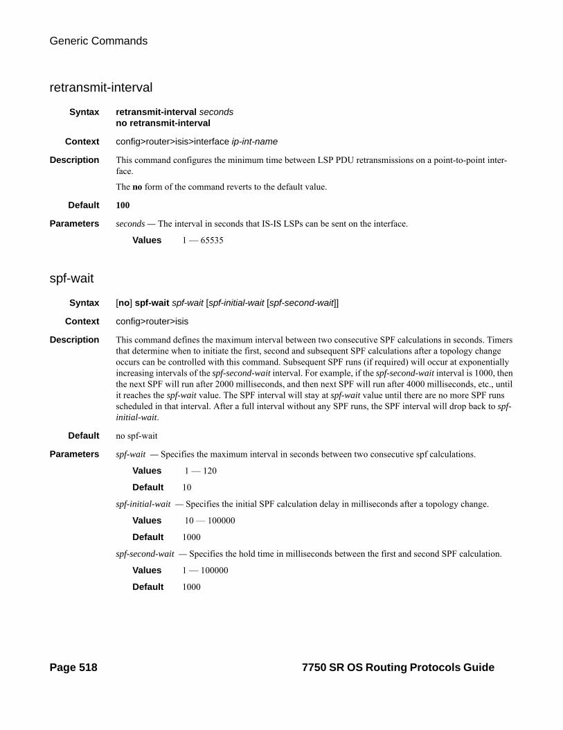
Generic Commands
retransmit-interval
Syntax retransmit-interval secondsno retransmit-interval
Context config>router>isis>interface ip-int-name
Description This command configures the minimum time between LSP PDU retransmissions on a point-to-point inter-face.
The no form of the command reverts to the default value.
Default 100
Parameters seconds — The interval in seconds that IS-IS LSPs can be sent on the interface.
Values 1 — 65535
spf-wait
Syntax [no] spf-wait spf-wait [spf-initial-wait [spf-second-wait]]
Context config>router>isis
Description This command defines the maximum interval between two consecutive SPF calculations in seconds. Timers that determine when to initiate the first, second and subsequent SPF calculations after a topology change occurs can be controlled with this command. Subsequent SPF runs (if required) will occur at exponentially increasing intervals of the spf-second-wait interval. For example, if the spf-second-wait interval is 1000, then the next SPF will run after 2000 milliseconds, and then next SPF will run after 4000 milliseconds, etc., until it reaches the spf-wait value. The SPF interval will stay at spf-wait value until there are no more SPF runs scheduled in that interval. After a full interval without any SPF runs, the SPF interval will drop back to spf-initial-wait.
Default no spf-wait
Parameters spf-wait — Specifies the maximum interval in seconds between two consecutive spf calculations.
Values 1 — 120
Default 10
spf-initial-wait — Specifies the initial SPF calculation delay in milliseconds after a topology change.
Values 10 — 100000
Default 1000
spf-second-wait — Specifies the hold time in milliseconds between the first and second SPF calculation.
Values 1 — 100000
Default 1000
Page 518 7750 SR OS Routing Protocols Guide

IS-IS
strict-adjacency-check
Syntax [no] strict-adjacency-check
Context config>router>isis
Description This command enables strict checking of address families (IPv4 and IPv6) for IS-IS adjacencies. When enabled, adjacencies will not come up unless both routers have exactly the same address families configured. If there is an existing adjacency with unmatched address families, it will be torn down. This command is used to prevent black-holing traffic when IPv4 and IPv6 topologies are different. When disabled (no strict-adjacency-check) a BFD session failure for either IPv4 or Ipv6 will cause the routes for the other address family to be removed as well.
When disabled (no strict-adjacency-check), both routers only need to have one common address family to establish the adjacency.
Default no strict-adjacency-check
summary-address
Syntax summary-address {ip-prefix/mask | ip-prefix [netmask]} level [tag tag]no summary-address {ip-prefix/mask | ip-prefix [netmask]}
Context config>router>isis
Description This command creates summary-addresses.
Default none
Parameters ip-prefix/mask — Specifies information for the specified IP prefix and mask length.
Values ipv4-prefix: a.b.c.d (host bits must be 0)ipv4-prefix-length: 0 — 32 ipv6-prefix: x:x:x:x:x:x:x:x (eight 16-bit pieces)
x:x:x:x:x:x:d.d.d.dx: [0 — FFFF]Hd: [0 — 255]D
ipv6-prefix-length: [0 — 128]
netmask — The subnet mask in dotted decimal notation.
Values 0.0.0.0 — 255.255.255.255 (network bits all 1 and host bits all 0)
level — Specifies IS-IS level area attributes.
Values level-1, level-2, level-1/2
tag tag — Assigns an OSPF, RIP or ISIS tag to routes matching the entry.
Values Accepts decimal or hex formats: OSPF and ISIS: [0x0..0xFFFFFFFF]HRIP: [0x0..0xFFFF]H
7750 SR OS Routing Protocols Guide Page 519

Generic Commands
suppress-default
Syntax [no] suppress-default
Context config>router>isis
Description This command enables or disables IS-IS to suppress the installation of default routes.
traffic-engineering
Syntax [no] traffic-engineering
Context config>router>isis
Description This command configures traffic-engineering and determines if IGP shortcuts are required by BGP.
Default disabled
unicast-import-disable
Syntax [no] unicast-import-disable
Context config>router>isis
Description This command allows one IGP to import its routes into RPF RTM while another IGP imports routes only into the unicast RTM. Import policies can redistribute routes from an IGP protocol into the RPF RTM (the multicast routing table). By default, the IGP routes will not be imported into RPF RTM as such an import policy must be explicitly configured.
Default disabled
wide-metrics-only
Syntax [no] wide-metrics-only
Context config>router>isis>level level-number
Description This command enables the exclusive use of wide metrics in the LSPs for the level number.. Narrow metrics can have values between 1 and 63. IS-IS can generate two TLVs, one for the adjacency and one for the IP prefix. In order to support traffic engineering, wider metrics are required. When wide metrics are used, a sec-ond pair of TLVs are added, again, one for the adjacency and one for the IP prefix.
By default, both sets of TLVs are generated. When wide-metrics-only is configured, IS-IS only generates the pair of TLVs with wide metrics for that level.
The no form of the command reverts to the default value.
Page 520 7750 SR OS Routing Protocols Guide

IS-IS
IS-IS Command Reference
Command Hierarchies
Configuration Commands
• Global Commands on page 521
• Interface Commands on page 522
• Show Commands on page 524
• Clear Commands on page 524
• Debug Commands on page 524
config— router
—Global Commands — [no] isis [instance-id]— [no] advertise-passive-only— [no] advertise-tunnel-links— all-l1isis ieee-address— no all-l1isis— all-l2isisieee-address— no all-l2isis— [no] area-id area-address— [no] authentication-check— authentication-key [authentication-key | hash-key] [hash | hash2]— no authentication-key— authentication-type {password | message-digest}— no authentication-type— [no] csnp-authentication— default-route-tag tag— no default-route-tag— [no] disable-ldp-sync— export policy-name [.. policy-name]— no export— export-limit number [log percentage]— no export-limit— [no] graceful-restart
— [no] helper-disable— [no] hello-authentication— [no] ipv4-routing— [no] ipv6-routing {native | mt}— [no] ldp-over-rsvp— level {1 | 2}
— authentication-key [authentication-key | hash-key] [hash | hash2]— no authentication-key— authentication-type {password | message-digest}— no authentication-type
7750 SR OS Routing Protocols Guide Page 521

Configuration Commands
— [no] csnp-authentication— default-metric ipv4 metric— no default-metric— external-preference external-preference— no external-preference— [no] hello-authentication— [no] loopfree-alternate-exclude— preference preference— no preference— [no] psnp-authentication— [no] wide-metrics-only
— level-capability {level-1 | level-2 | level-1/2}— [no] loopfree-alternate— lsp-lifetime seconds— no lsp-lifetime— lsp-mtu-size size— no lsp-mtu-size— [no] lsp-wait lsp-wait [lsp-initial-wait [lsp-second-wait]]— [no] mcast-import-ipv6 — [no] multi-topology
— [no] ipv6-unicast— [no] multicast-import— overload [timeout seconds]— no overload— overload-on-boot [timeout seconds]— no overload-on-boot— [no] psnp-authentication— reference-bandwidth reference-bandwidth — no reference-bandwidth— [no] rsvp-shortcut— [no] shutdown— [no] spf-wait spf-wait [spf-initial-wait [spf-second-wait]]— [no] strict-adjacency-check— [no] suppress-default— summary-address {ip-prefix/mask | ip-prefix [netmask]} level [tag tag]— no summary-address {ip-prefix/mask | ip-prefix [netmask]}— [no] traffic-engineering — [no] unicast-import-disable
—Interface Commands — [no] interface ip-int-name — [no] bfd-enable {ipv4 | ipv6}— csnp-interval seconds— no csnp-interval— hello-authentication-key [authentication-key | hash-key][hash | hash2]— no hello-authentication-key— hello-authentication-type {password | message-digest}— no hello-authentication-type— interface-type {broadcast | point-to-point}— no interface-type— [no] metric— level {1 | 2}
— hello-authentication-key [authentication-key | hash-key] [hash | hash2]
— no hello-authentication-key— hello-authentication-type [password | message-digest]
Page 522 7750 SR OS Routing Protocols Guide

IS-IS
— no hello-authentication-type— hello-interval seconds— no hello-interval— hello-multiplier multiplier— no hello-multiplier— ipv6-unicast-metric metric— no ipv6-unicast-metric— metric metric— no metric— [no] passive— priority number— no priority
— level-capability {level-1 | level-2 | level-1/2}— lsp-pacing-interval milli-seconds— no lsp-pacing-interval— [no] loopfree-alternate-exclude— [no] loopfree-alternate— mesh-group [value | blocked]— no mesh-group— [no] passive— retransmit-interval seconds— no retransmit-interval— [no] shutdown— tag tag— no tag
7750 SR OS Routing Protocols Guide Page 523
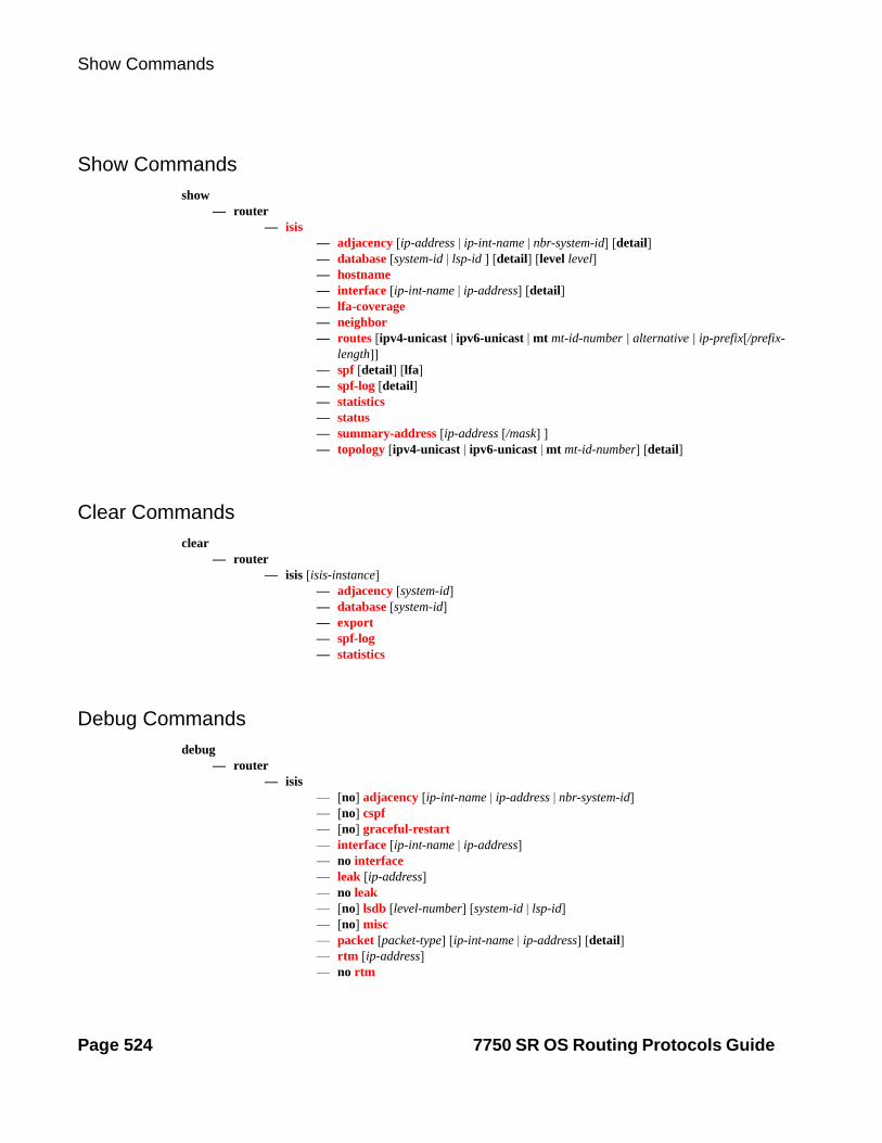
Show Commands
—Show Commands
Show Commands
show— router
— isis— adjacency [ip-address | ip-int-name | nbr-system-id] [detail]— database [system-id | lsp-id ] [detail] [level level]— hostname — interface [ip-int-name | ip-address] [detail]— lfa-coverage— neighbor— routes [ipv4-unicast | ipv6-unicast | mt mt-id-number | alternative | ip-prefix[/prefix-
length]]— spf [detail] [lfa]— spf-log [detail]— statistics— status— summary-address [ip-address [/mask] ]— topology [ipv4-unicast | ipv6-unicast | mt mt-id-number] [detail]
Clear Commands—Clear Commands clear
— router— isis [isis-instance]
— adjacency [system-id]— database [system-id]— export— spf-log— statistics
Debug Commands
debug— router
— isis— [no] adjacency [ip-int-name | ip-address | nbr-system-id]— [no] cspf— [no] graceful-restart— interface [ip-int-name | ip-address]— no interface— leak [ip-address]— no leak— [no] lsdb [level-number] [system-id | lsp-id]— [no] misc— packet [packet-type] [ip-int-name | ip-address] [detail]— rtm [ip-address]— no rtm
Page 524 7750 SR OS Routing Protocols Guide

IS-IS
— [no] spf [level-number] [system-id]
7750 SR OS Routing Protocols Guide Page 525

Debug Commands
Page 526 7750 SR OS Routing Protocols Guide

IS-IS
Show Commands
isis
Syntax isis [isis-instance]
Context show>router
Description This command displays information for a specified IS-IS instance.
Parameters instance-id — Specifies the instance ID for an IS-IS instance.
Values 1–31
Default 0
adjacency
Syntax adjacency [ip-address | ip-int-name | nbr-system-id] [detail]
Context show>router>isis
Description This command displays information regarding IS-IS neighbors. When no ip-address, ip-int-name, or nbr-system-id are specified, then all adjacencies display.
Parameters ip-address — When specified, only adjacencies with that interface display.
Values ipv4-address: a.b.c.d (host bits must be 0)ipv6-address: x:x:x:x:x:x:x:x (eight 16-bit pieces)
x:x:x:x:x:x:d.d.d.dx: [0 — FFFF]Hd: [0 — 255]D
ip-int-name — When specified, only adjacencies with that interface display.
nbr-system-id — When pecified, only the adjacency with that ID displays.
detail — All output displays in the detailed format.
Output Standard and Detailed IS-IS Adjacency Output — The following table describes the standard and detailed command output fields for an IS-IS adjacency.
Label Description
Interface Interface name associated with the neighbor.
System-id Neighbor’s system ID.
Level 1-L1 only, 2-L2 only, 3-L1 and L2.
State Up, down, new, one-way, initializing, or rejected.
7750 SR OS Routing Protocols Guide Page 527

Show Commands
Sample Output
*A:Dut-A# show router isis adjacency ===============================================================================ISIS Adjacency===============================================================================System ID Usage State Hold Interface MT Enab-------------------------------------------------------------------------------Dut-B L1 Up 2 ip-3FFE::A0A:101 Yes Dut-B L2 Up 2 ip-3FFE::A0A:101 Yes Dut-F L1L2 Up 5 ies-1-3FFE::A0A:1501 Yes -------------------------------------------------------------------------------Adjacencies : 3===============================================================================*A:Dut-A#
*A:ALA-A# show router isis adjacency 180.0.7.12===============================================================================ISIS Adjacency===============================================================================System ID Usage State Hold Interface-------------------------------------------------------------------------------asbr_east L2 Up 25 if2/5-------------------------------------------------------------------------------Adjacencies : 1===============================================================================
Hold Hold time remaining for the adjacency.
SNPA Subnetwork point of attachment, MAC address of the next hop.
Circuit type Level on the interface L1, L2, or both.
Expires In Number of seconds until adjacency expires.
Priority Priority to become designated router.
Up/down transi-tions
Number of times neighbor state has changed.
Event Event causing last transition.
Last transition Time since last transition change.
Speaks Supported protocols (only IP).
IP address IP address of neighbor.
MT enab Yes — The neighbor is advertising at least 1 non MTID#0.
Topology Derived from the MT TLV in the IIH• MT#0, MT#2 => “Topology : Unicast, IPv6-Unicast”• Native IPv4 or native IPv6 => “Topology : Unicast”Not supported MTID's => Topology line suppressed
Label Description (Continued)
Page 528 7750 SR OS Routing Protocols Guide

IS-IS
*A:ALA-A#
*A:ALA-A# show router isis adjacency if2/5===============================================================================ISIS Adjacency===============================================================================System ID Usage State Hold Interface-------------------------------------------------------------------------------asbr_east L2 Up 20 if2/5-------------------------------------------------------------------------------Adjacencies : 1===============================================================================*A:ALA-A#
*A:Dut-A# show router isis adjacency detail ===============================================================================ISIS Adjacency===============================================================================SystemID : Dut-B SNPA : 20:81:01:01:00:01 Interface : ip-3FFE::A0A:101 Up Time : 0d 00:56:10 State : Up Priority : 64 Nbr Sys Typ : L1 L. Circ Typ : L1 Hold Time : 2 Max Hold : 2 Adj Level : L1 MT Enabled : Yes Topology : Unicast, IPv6-Unicast IPv6 Neighbor : FE80::2281:1FF:FE01:1IPv4 Neighbor : 10.10.1.2Restart Support : DisabledRestart Status : Not currently being helpedRestart Supressed : DisabledNumber of Restarts: 0Last Restart at : Never SystemID : Dut-B SNPA : 20:81:01:01:00:01 Interface : ip-3FFE::A0A:101 Up Time : 0d 00:56:10 State : Up Priority : 64 Nbr Sys Typ : L2 L. Circ Typ : L2 Hold Time : 2 Max Hold : 2 Adj Level : L2 MT Enabled : Yes Topology : Unicast, IPv6-Unicast IPv6 Neighbor : FE80::2281:1FF:FE01:1IPv4 Neighbor : 10.10.1.2Restart Support : DisabledRestart Status : Not currently being helpedRestart Supressed : DisabledNumber of Restarts: 0Last Restart at : Never SystemID : Dut-F SNPA : 00:00:00:00:00:00 Interface : ies-1-3FFE::A0A:1501 Up Time : 0d 01:18:34 State : Up Priority : 0 Nbr Sys Typ : L1L2 L. Circ Typ : L1L2 Hold Time : 5 Max Hold : 6 Adj Level : L1L2 MT Enabled : Yes Topology : Unicast, IPv6-Unicast
7750 SR OS Routing Protocols Guide Page 529

Show Commands
IPv6 Neighbor : FE80::2285:FFFF:FE00:0IPv4 Neighbor : 10.10.21.6Restart Support : DisabledRestart Status : Not currently being helpedRestart Supressed : DisabledNumber of Restarts: 0Last Restart at : Never===============================================================================*A:Dut-A#
A:Dut-A# show router isis status===============================================================================ISIS Status===============================================================================System Id : 0100.2000.1001Admin State : UpIpv4 Routing : EnabledIpv6 Routing : DisabledLast Enabled : 08/28/2006 10:22:17Level Capability : L2Authentication Check : TrueAuthentication Type : NoneCSNP-Authentication : EnabledHELLO-Authentication : EnabledPSNP-Authentication : EnabledTraffic Engineering : EnabledGraceful Restart : DisabledGR Helper Mode : DisabledLSP Lifetime : 1200LSP Wait : 1 sec (Max) 1 sec (Initial) 1 sec (Second)Adjacency Check : looseL1 Auth Type : noneL2 Auth Type : noneL1 CSNP-Authenticati*: EnabledL1 HELLO-Authenticat*: EnabledL1 PSNP-Authenticati*: EnabledL1 Preference : 15L2 Preference : 18L1 Ext. Preference : 160L2 Ext. Preference : 165L1 Wide Metrics : DisabledL2 Wide Metrics : EnabledL1 LSDB Overload : DisabledL2 LSDB Overload : DisabledL1 LSPs : 0L2 LSPs : 15Last SPF : 08/28/2006 10:22:25SPF Wait : 1 sec (Max) 10 ms (Initial) 10 ms (Second)Export Policies : NoneArea Addresses : 49.0001===============================================================================* indicates that the corresponding row element may have been truncated.A:Dut-A#
Page 530 7750 SR OS Routing Protocols Guide

IS-IS
database
Syntax database [system-id | lsp-id] [detail] [level level]
Context show>router>isis
Description This command displays the entries in the IS-IS link state database.
Parameters system-id — Only the LSPs related to that system-id are listed. If no system-id or lsp-id are specified, all database entries are listed.
lsp-id — Only the specified LSP (hostname) is listed. If no system-id or lsp-id are specified, all database entries are listed.
detail — All output is displayed in the detailed format.
level level — Only the specified IS-IS protocol level attributes are displayed.
Output IS-IS Database Output — The following table describes the IS-IS database output.
Label Description
LSP ID LSP IDs are auto-assigned by the originating IS-IS node. The LSP ID is comprised of three sections. The first 6 bytes is the system ID for that node, followed by a single byte value for the pseudonode gener-ated by that router, then finally, a fragment byte which starts at zero. For example, if a router’s system ID is 1800.0000.0029, the first LSP ID is 1800.0000.0029.00-00. If there are too many routes, LSP ID 1800.0000.0029.00-01 is created to contain the excess routes. If the router is the Designated Intermediate System (DIS) on a broadcast net-work, a pseudo-node LSP is created. Usually the internal circuit ID is used to determine the ID assigned to the pseudonode. For instance, for circuit 4, a LSP pseudonode with ID 1800.0000.0029.04-00 is created. The 7750 SR OS learns hostnames and uses the hostname in place of the system ID. An example of LDP IDs are: acc_arl.00-00 acc_arl.00-01 acc_arl.04-00
Sequence The sequence number of the LSP that allows other systems to deter-mine if they have received the latest information from the source.
Checksum The checksum of the entire LSP packet.
Lifetime Amount of time, in seconds, that the LSP remains valid.
Attributes OV — The overload bit is set.
L1 — Specifies a Level 1 IS type.
L2 — Specifies a Level 2 IS type.
ATT — The attach bit is set. When this bit is set, the router can also act as a Level 2 router and can reach other areas.
7750 SR OS Routing Protocols Guide Page 531

Show Commands
Sample Output
*A:ALA-A# show router isis database===============================================================================ISIS Database===============================================================================LSP ID Sequence Checksum Lifetime Attributes
LSP Count A sum of all the configured Level 1 and Level 2 LSPs.
LSP ID Displays a unique identifier for each LSP composed of SysID, Pseudonode ID and LSP name.
Lifetime Displays the remaining time until the LSP expires.
Version Displays the version/protocol ID extension. This value is always set to 1.
Pkt Type Displays the PDU type number.
Pkt Ver Displays the version/protocol ID extension. This value is always set to 1.
Max Area Displays the maximum number of area addresses supported.
Sys ID Len Displays the length of the system ID field (0 or 6 for 6 digits).
Use Len The actual length of the PDU.
Alloc Len The amount of memory space allocated for the LSP.
Area Address Displays the area addresses to which the router is connected.
Supp Protocols Displays the data protocols that are supported.
IS-Hostname The name of the router originating the LSP.
Virtual Flag 0 — Level 1 intermediate systems report this octet as 0 to all neigh-bors.
1 — Indicates that the path to a neighbor is a Level 2 virtual path used to repair an area partition.
Neighbor Displays the routers running interfaces to which the router is con-nected.
Internal Reach Displays a 32-bit metric. A bit is added for the ups and downs resulting from Level 2 to Level 1 route-leaking.
IP Prefix Displays the IP addresses that the router knows about by externally-originated interfaces.
Metrics Displays a routing metric used in the IS-IS link-state calculation.
Label Description (Continued)
Page 532 7750 SR OS Routing Protocols Guide

IS-IS
-------------------------------------------------------------------------------Displaying Level 1 database-------------------------------------------------------------------------------abr_dfw.00-00 0x50 0x164f 603 L1L2Level (1) LSP Count : 1Displaying Level 2 database-------------------------------------------------------------------------------asbr_east.00-00 0x53 0xe3f5 753 L1L2abr_dfw.00-00 0x57 0x94ff 978 L1L2abr_dfw.03-00 0x50 0x14f1 614 L1L2Level (2) LSP Count : 3===============================================================================*A:ALA-A#
*A:Dut-B# show router isis database Dut-A.00-00 detail ==============================================================================ISIS Database==============================================================================Displaying Level 1 database------------------------------------------------------------------------------Level (1) LSP Count : 0
Displaying Level 2 database------------------------------------------------------------------------------LSP ID : Dut-A.00-00 Level : L2 Sequence : 0x6 Checksum : 0xb7c4 Lifetime : 1153 Version : 1 Pkt Type : 20 Pkt Ver : 1 Attributes: L1L2 Max Area : 3 SysID Len : 6 Used Len : 311 Alloc Len : 311 TLVs : Area Addresses: Area Address : (2) 30.31 Supp Protocols: Protocols : IPv4 IS-Hostname : Dut-A Router ID : Router ID : 10.20.1.1 I/F Addresses : I/F Address : 10.20.1.1 I/F Address : 10.10.1.1 I/F Address : 10.10.2.1 TE IS Nbrs : Nbr : Dut-B.01 Default Metric : 1000 Sub TLV Len : 98 IF Addr : 10.10.1.1 MaxLink BW: 100000 kbps Resvble BW: 100000 kbps Unresvd BW: BW[0] : 10000 kbps BW[1] : 40000 kbps BW[2] : 40000 kbps BW[3] : 40000 kbps BW[4] : 50000 kbps BW[5] : 50000 kbps BW[6] : 50000 kbps BW[7] : 10000 kbps
7750 SR OS Routing Protocols Guide Page 533

Show Commands
Admin Grp : 0x0 TE Metric : 1000 SUBTLV BW CONSTS : 8 BW Model : 1 BC[0]: 10000 kbps BC[1]: 0 kbps BC[2]: 40000 kbps BC[3]: 0 kbps BC[4]: 0 kbps BC[5]: 50000 kbps BC[6]: 0 kbps BC[7]: 0 kbps TE IP Reach : Default Metric : 0 Control Info: , prefLen 32 Prefix : 10.20.1.1 Default Metric : 1000 Control Info: , prefLen 24 Prefix : 10.10.1.0 Default Metric : 1000 Control Info: , prefLen 24 Prefix : 10.10.2.0
Level (2) LSP Count : 1==============================================================================*A:Dut-B#
hostname
Syntax hostname
Context show>router>isis
Description This command displays the hostname database. There are no options or parameters.
Output IS-IS Hostname Output — The following table describes output fields for IS-IS hostname output.
Label Description
System-id System identifier mapped to hostname.
Hostname Hostname for the specific system-id.
Type The type of entry (static or dynamic).
Sample Output
A:ALA-A# show router isis hostname=========================================================================Hosts=========================================================================System Id Hostname-------------------------------------------------------------------------1800.0000.0002 core_west1800.0000.0005 core_east
Page 534 7750 SR OS Routing Protocols Guide
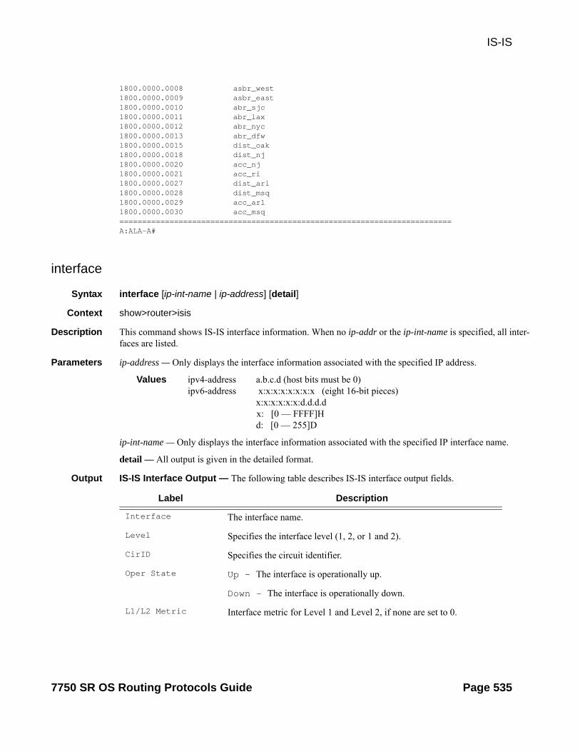
IS-IS
1800.0000.0008 asbr_west1800.0000.0009 asbr_east1800.0000.0010 abr_sjc1800.0000.0011 abr_lax1800.0000.0012 abr_nyc1800.0000.0013 abr_dfw1800.0000.0015 dist_oak1800.0000.0018 dist_nj1800.0000.0020 acc_nj1800.0000.0021 acc_ri1800.0000.0027 dist_arl1800.0000.0028 dist_msq1800.0000.0029 acc_arl1800.0000.0030 acc_msq=========================================================================A:ALA-A#
interface
Syntax interface [ip-int-name | ip-address] [detail]
Context show>router>isis
Description This command shows IS-IS interface information. When no ip-addr or the ip-int-name is specified, all inter-faces are listed.
Parameters ip-address — Only displays the interface information associated with the specified IP address.
Values ipv4-address a.b.c.d (host bits must be 0)ipv6-address x:x:x:x:x:x:x:x (eight 16-bit pieces)
x:x:x:x:x:x:d.d.d.d x: [0 — FFFF]H d: [0 — 255]D
ip-int-name — Only displays the interface information associated with the specified IP interface name.
detail — All output is given in the detailed format.
Output IS-IS Interface Output — The following table describes IS-IS interface output fields.
Label Description
Interface The interface name.
Level Specifies the interface level (1, 2, or 1 and 2).
CirID Specifies the circuit identifier.
Oper State Up — The interface is operationally up.
Down — The interface is operationally down.
L1/L2 Metric Interface metric for Level 1 and Level 2, if none are set to 0.
7750 SR OS Routing Protocols Guide Page 535

Show Commands
Sample Output
A:ALA-A# show router isis interface===============================================================================ISIS Interfaces===============================================================================Interface Level CircID Oper State L1/L2 Metric-------------------------------------------------------------------------------system L1L2 1 Up 10/10if2/1 L2 8 Up -/10if2/2 L1 5 Up 10/-if2/3 L1 6 Up 10/-if2/4 L1 7 Up 10/-if2/5 L2 2 Up -/10lag-1 L2 3 Up -/10if2/8 L2 4 Up -/10-------------------------------------------------------------------------------Interfaces : 8===============================================================================A:ALA-A#
A:SetupCLI# show router isis interface detail=======================================================================ISIS Interfaces=======================================================================-----------------------------------------------------------------------Interface : system Level Capability: L2Oper State : Up Admin State : UpAuth Type : None Auth State : EnabledCircuit Id : 1 Retransmit Int. : 65535Type : Pt-to-Pt LSP Pacing Int. : 100CSNP Int. : 22Mesh Group : 54Bfd Enabled : YesTe Metric : 0 Te State : DownAdmin Groups : NoneLdp Sync : outOfService Ldp Sync Wait : DisabledLdp Timer State: Disabled Ldp Tm Left : 0Route Tag : 4294967295 LFA : Included
Level : 2 Adjacencies : 0 Auth Type : None Metric : 0 Hello Timer : 9 Hello Mult. : 3 Priority : 64 IPv6-Ucast-Met : 0 Passive : No----------------------------------------------------------------------------Interface : ip_if_1 Level Capability: L1L2Oper State : Down Admin State : DownAuth Type : None Auth State : EnabledCircuit Id : 5 Retransmit Int. : 65535Type : Pt-to-Pt LSP Pacing Int. : 100CSNP Int. : 22Mesh Group : 54Bfd Enabled : YesTe Metric : 0 Te State : DownAdmin Groups : NoneLdp Sync : outOfService Ldp Sync Wait : DisabledLdp Timer State: Disabled Ldp Tm Left : 0
Page 536 7750 SR OS Routing Protocols Guide

IS-IS
Route Tag : 4294967295 LFA : Included
Level : 1 Adjacencies : 0 Auth Type : Password Metric : 1 Hello Timer : 20000 Hello Mult. : 100 Priority : 1 IPv6-Ucast-Met : 10 Passive : Yes
Level : 2 Adjacencies : 0 Auth Type : Password Metric : 1 Hello Timer : 20000 Hello Mult. : 100 Priority : 1 IPv6-Ucast-Met : 10 Passive : Yes
-----------------------------------------------------------------------Interface : LOA1 Level Capability: L1L2Oper State : Down Admin State : UpAuth Type : None Auth State : EnabledCircuit Id : 49 Retransmit Int. : 5Type : Broadcast LSP Pacing Int. : 100CSNP Int. : 10Mesh Group : InactiveBfd Enabled : NoTe Metric : 0 Te State : DownAdmin Groups : NoneLdp Sync : outOfService Ldp Sync Wait : DisabledLdp Timer State: Disabled Ldp Tm Left : 0Route Tag : None LFA : Excluded
Level : 1 Adjacencies : 0 Desg. IS : 0000.0000.0000 Auth Type : None Metric : 1000 Hello Timer : 9 Hello Mult. : 3 Priority : 64 IPv6-Ucast-Met : 1000 Passive : No
Level : 2 Adjacencies : 0 Desg. IS : 0000.0000.0000 Auth Type : None Metric : 1000 Hello Timer : 9 Hello Mult. : 3 Priority : 64 IPv6-Ucast-Met : 1000 Passive : No
lfa-coverage
Syntax lfa-coverage
Context show>router>isis
Description This command displays IS-IS LFA coverage information.
Sample Output
*A:SR# show router isis lfa-coverage
7750 SR OS Routing Protocols Guide Page 537

Show Commands
============================================================================LFA Coverage============================================================================Topology Level Node IPv4 ----------------------------------------------------------------------------IPV4 Unicast L1 4/4(100%) 826/826(100%) IPV4 Unicast L2 2/2(100%) 826/826(100%) IPV6 Unicast L1 3/3(100%) 0/0(0%) IPV6 Unicast L2 0/0(0%) 0/0(0%) ============================================================================*A:SR#
*A:SRR>config>router>isis# show router isis lfa-coverage ===============================================================================LFA Coverage===============================================================================Topology Level Node IPv4 IPv6-------------------------------------------------------------------------------IPV4 Unicast L1 3/4(75%) 1484/1975(75%) 0/0(0%)IPV4 Unicast L2 3/3(100%) 1484/1975(75%) 0/0(0%)===============================================================================*A:SRR>config>router>isis#
neighbor
Syntax neighbor
Context show>router>isis
Description This command displays neighboring route information in the IS-IS route table.
Sample Output
A:linus-212# show router isis neighbor
============================================================================Topology Table============================================================================Node Interface Nexthop--------------------------------------------------------------------------------------------------------------------------------------------------------IS-IS IP paths (MT-ID 0), Level 1----------------------------------------------------------------------------linus-211.00 ab linus-211linus-216.00 ab linus-211linus-216.01 ab linus-211----------------------------------------------------------------------------IS-IS IP paths (MT-ID 0), Level 2----------------------------------------------------------------------------linus-211.00 ab linus-211linus-216.00 ab linus-211linus-216.01 ab linus-211============================================================================
Page 538 7750 SR OS Routing Protocols Guide

IS-IS
routes
Syntax routes [ipv4-unicast | ipv6-unicast | mt mt-id-number | alternative | ip-prefix[/prefix-length]]
Context show>router>isis
Description This command displays the routes in the IS-IS route table.
Parameters ipv4-unicast — Displays IPv4 unicast parameters.
ipv6-unicast — Displays IPv6 unicast parameters.
mt mt-id-number — Displays multi-topology parameters.
Values 0, 2
alternative — Displays LFA details.
Output IS-IS Route Output — The following table describes IS-IS route output fields.
Label Description
Prefix The route prefix and mask.
Metric MT The route’s metric.
Lvl/Type Specifies the level (1 or 2) and the route type, Internal (Int) or External (Ext).
Version SPF version that generated route.
Nexthop System ID of nexthop, give hostname if possible.
Hostname Hostname for the specific system-id.
Sample Output
*A:Dut-B# show router isis routes============================================================================Route Table============================================================================Prefix [Flags] Metric Lvl/Typ Ver. SysID/Hostname NextHop MT AdminTag----------------------------------------------------------------------------10.20.1.2/32 0 1/Int. 3 Dut-B 0.0.0.0 0 010.20.1.3/32 [L] 10 2/Int. 2 Dut-C 10.20.3.3 0 010.20.1.4/32 10 2/Int. 3 Dut-D 10.20.4.4 0 010.20.1.5/32 20 2/Int. 3 Dut-C 10.20.3.3 0 010.20.1.6/32 20 2/Int. 3 Dut-D 10.20.4.4 0 010.20.3.0/24 10 1/Int. 3 Dut-B 0.0.0.0 0 010.20.4.0/24 10 1/Int. 3 Dut-B
7750 SR OS Routing Protocols Guide Page 539

Show Commands
0.0.0.0 0 010.20.5.0/24 20 2/Int. 2 Dut-C 10.20.3.3 0 010.20.6.0/24 20 2/Int. 4 Dut-D 10.20.4.4 0 010.20.9.0/24 20 2/Int. 3 Dut-D 10.20.4.4 0 010.20.10.0/24 30 2/Int. 3 Dut-C 10.20.3.3 0 0----------------------------------------------------------------------------Routes : 11Flags: L = LFA nexthop available ============================================================================*A:Dut-B#
*A:Dut-B# show router isis routes alternative
============================================================================Route Table============================================================================Prefix [Flags] Metric Lvl/Typ Ver. SysID/Hostname NextHop MT AdminTagAlt-Nexthop Alt-Metric----------------------------------------------------------------------------10.20.1.2/32 0 1/Int. 3 Dut-B 0.0.0.0 0 010.20.1.3/32 10 2/Int. 2 Dut-C 10.20.3.3 0 0 10.20.3.3 (lfa) 1510.20.1.4/32 10 2/Int. 3 Dut-D 10.20.4.4 0 010.20.1.5/32 20 2/Int. 3 Dut-C 10.20.3.3 0 010.20.1.6/32 20 2/Int. 3 Dut-D 10.20.4.4 0 010.20.3.0/24 10 1/Int. 3 Dut-B 0.0.0.0 0 010.20.4.0/24 10 1/Int. 3 Dut-B 0.0.0.0 0 010.20.5.0/24 20 2/Int. 2 Dut-C 10.20.3.3 0 010.20.6.0/24 20 2/Int. 4 Dut-D 10.20.4.4 0 010.20.9.0/24 20 2/Int. 3 Dut-D 10.20.4.4 0 010.20.10.0/24 30 2/Int. 3 Dut-C 10.20.3.3 0 0----------------------------------------------------------------------------Routes : 11Flags: LFA = Loop-Free Alternate nexthop============================================================================*A:Dut-B#
*A:Dut-A# show router isis routes ===============================================================================Route Table===============================================================================Prefix Metric Lvl/Typ Ver. SysID/Hostname NextHop MT
Page 540 7750 SR OS Routing Protocols Guide

IS-IS
-------------------------------------------------------------------------------10.10.1.0/24 10 1/Int. 5 Dut-A 0.0.0.0 010.10.3.0/24 20 1/Int. 137 Dut-B 10.10.1.2 010.10.4.0/24 20 1/Int. 137 Dut-B 10.10.1.2 010.10.5.0/24 30 1/Int. 137 Dut-B 10.10.1.2 010.10.9.0/24 60 1/Int. 52 Dut-F 10.10.21.6 010.10.10.0/24 70 1/Int. 52 Dut-F 10.10.21.6 010.10.12.0/24 20 1/Int. 137 Dut-B 10.10.1.2 010.10.13.0/24 10 1/Int. 7 Dut-A 0.0.0.0 010.10.14.0/24 20 1/Int. 52 Dut-F 10.10.21.6 010.10.15.0/24 30 1/Int. 137 Dut-B 10.10.1.2 010.10.16.0/24 30 1/Int. 137 Dut-B 10.10.1.2 010.10.21.0/24 10 1/Int. 48 Dut-A 0.0.0.0 010.10.22.0/24 30 1/Int. 137 Dut-B 10.10.1.2 010.20.1.1/32 0 1/Int. 10 Dut-A 0.0.0.0 010.20.1.2/32 10 1/Int. 137 Dut-B 10.10.1.2 010.20.1.3/32 20 1/Int. 137 Dut-B 10.10.1.2 010.20.1.4/32 20 1/Int. 137 Dut-B 10.10.1.2 010.20.1.5/32 30 1/Int. 137 Dut-B 10.10.1.2 010.20.1.6/32 10 1/Int. 52 Dut-F 10.10.21.6 03FFE::A0A:100/120 10 1/Int. 5 Dut-A :: 010.10.1.0/24 10 1/Int. 65 Dut-A 0.0.0.0 210.10.13.0/24 10 1/Int. 65 Dut-A 0.0.0.0 210.10.21.0/24 10 1/Int. 65 Dut-A 0.0.0.0 210.20.1.1/32 0 1/Int. 65 Dut-A 0.0.0.0 23FFE::A0A:100/120 10 1/Int. 65 Dut-A :: 23FFE::A0A:300/120 20 1/Int. 116 Dut-B FE80::2281:1FF:FE01:1-"ip-3FFE::A0A:101" 23FFE::A0A:400/120 20 1/Int. 116 Dut-B FE80::2281:1FF:FE01:1-"ip-3FFE::A0A:101" 23FFE::A0A:500/120 30 1/Int. 130 Dut-B FE80::2281:1FF:FE01:1-"ip-3FFE::A0A:101" 23FFE::A0A:900/120 60 1/Int. 71 Dut-F FE80::2285:FFFF:FE00:0-"ies-1-3FFE::A0A:1501" 2
7750 SR OS Routing Protocols Guide Page 541

Show Commands
3FFE::A0A:A00/120 70 1/Int. 71 Dut-F FE80::2285:FFFF:FE00:0-"ies-1-3FFE::A0A:1501" 23FFE::A0A:C00/120 20 1/Int. 116 Dut-B FE80::2281:1FF:FE01:1-"ip-3FFE::A0A:101" 23FFE::A0A:D00/120 10 1/Int. 65 Dut-A :: 23FFE::A0A:E00/120 20 1/Int. 71 Dut-F FE80::2285:FFFF:FE00:0-"ies-1-3FFE::A0A:1501" 23FFE::A0A:F00/120 30 1/Int. 130 Dut-B FE80::2281:1FF:FE01:1-"ip-3FFE::A0A:101" 23FFE::A0A:1000/120 30 1/Int. 130 Dut-B FE80::2281:1FF:FE01:1-"ip-3FFE::A0A:101" 23FFE::A0A:1500/120 10 1/Int. 65 Dut-A :: 23FFE::A0A:1600/120 30 1/Int. 127 Dut-B FE80::2281:1FF:FE01:1-"ip-3FFE::A0A:101" 23FFE::A14:101/128 0 1/Int. 65 Dut-A :: 23FFE::A14:102/128 10 1/Int. 116 Dut-B FE80::2281:1FF:FE01:1-"ip-3FFE::A0A:101" 23FFE::A14:103/128 20 1/Int. 130 Dut-B FE80::2281:1FF:FE01:1-"ip-3FFE::A0A:101" 23FFE::A14:104/128 20 1/Int. 127 Dut-B FE80::2281:1FF:FE01:1-"ip-3FFE::A0A:101" 23FFE::A14:105/128 30 1/Int. 130 Dut-B FE80::2281:1FF:FE01:1-"ip-3FFE::A0A:101" 23FFE::A14:106/128 10 1/Int. 71 Dut-F FE80::2285:FFFF:FE00:0-"ies-1-3FFE::A0A:1501" 2-------------------------------------------------------------------------------Routes : 43===============================================================================*A:Dut-A#
*A:SRR# show router isis routes 1.1.1.0/24 ===============================================================================Route Table===============================================================================Prefix[Flags] Metric Lvl/Typ Ver. SysID/Hostname NextHop MT AdminTag -------------------------------------------------------------------------------1.1.1.0/24 [L] 7540 1/Int. 6109 SRL 60.60.1.1 0 0-------------------------------------------------------------------------------No. of Routes: 1Flags: L = LFA nexthop available===============================================================================*A:SRR# show router isis routes 1.1.1.0/24 alternative ===============================================================================Route Table===============================================================================Prefix[Flags] Metric Lvl/Typ Ver. SysID/Hostname NextHop MT AdminTag Alt-Nexthop Alt-Metric Alt-Type -------------------------------------------------------------------------------1.1.1.0/24 7550 1/Int. 6114 SRL 60.60.1.1 0 0 11.22.12.4 (LFA) 16784764 linkProtection-------------------------------------------------------------------------------No. of Routes: 1
Page 542 7750 SR OS Routing Protocols Guide

IS-IS
Flags: LFA = Loop-Free Alternate nexthop===============================================================================*A:SRR#
*A:SRR# show router isis routes 1.1.1.0/24 ===============================================================================Route Table===============================================================================Prefix[Flags] Metric Lvl/Typ Ver. SysID/Hostname NextHop MT AdminTag -------------------------------------------------------------------------------1.1.1.0/24 [L] 7540 1/Int. 6109 SRL 60.60.1.1 0 0-------------------------------------------------------------------------------No. of Routes: 1Flags: L = LFA nexthop available===============================================================================*A:SRR# show router isis routes 1.1.1.0/24 alternative ===============================================================================Route Table===============================================================================Prefix[Flags] Metric Lvl/Typ Ver. SysID/Hostname NextHop MT AdminTag Alt-Nexthop Alt-Metric Alt-Type -------------------------------------------------------------------------------1.1.1.0/24 7550 1/Int. 6114 SRL 60.60.1.1 0 0 11.22.12.4 (LFA) 16784764 linkProtection-------------------------------------------------------------------------------No. of Routes: 1Flags: LFA = Loop-Free Alternate nexthop===============================================================================*A:SRR#
spf
Syntax spf [detail] [lfa]
Context show>router>isis
Description This command displays information regarding SPF calculation.
Output Router ISIS Output — The following table describes the output fields for ISIS SPF.
Label Description
Node The route node and mask.
Interface The outgoing interface name for the route.
Metric The route’s metric.
Nexthop The system ID of nexthop or hostname.
7750 SR OS Routing Protocols Guide Page 543

Show Commands
Sample Output
linus-212>show>router>isis# show router isis spf============================================================================Path Table============================================================================Node Interface Nexthop----------------------------------------------------------------------------linus-211.00 ab linus-211x linux-222 *linus-216.00 ab linus-211linus-216.00 ab linus-211linus-216.01 ab linus-211============================================================================
A:ALA-A# show router isis spf===============================================================================Path Table===============================================================================Node Interface Nexthop-------------------------------------------------------------------------------abr_sjc.00 if2/2 dist_oakabr_sjc.00 if2/3 dist_njdist_oak.00 if2/2 dist_oakdist_nj.00 if2/3 dist_njacc_nj.00 if2/3 dist_njacc_ri.00 if2/3 dist_njcore_west.00 if2/8 core_westcore_east.00 lag-1 core_eastasbr_west.00 if2/8 core_westasbr_east.00 if2/5 asbr_eastabr_sjc.00 lag-1 core_eastabr_sjc.00 if2/8 core_westabr_lax.00 lag-1 core_eastabr_lax.00 if2/8 core_westabr_dfw.00 if2/5 asbr_eastabr_dfw.00 lag-1 core_eastabr_dfw.00 if2/8 core_westdist_arl.00 if2/5 asbr_eastdist_arl.00 lag-1 core_eastdist_arl.00 if2/8 core_westdist_msq.00 if2/5 asbr_eastdist_msq.00 lag-1 core_eastdist_msq.00 if2/8 core_westacc_arl.00 if2/5 asbr_eastacc_arl.00 lag-1 core_eastacc_arl.00 if2/8 core_westacc_msq.00 if2/5 asbr_eastacc_msq.00 lag-1 core_eastacc_msq.00 if2/8 core_westacc_msq.03 if2/5 asbr_east
SNPA The Subnetwork Points of Attachment (SNPA) where a router is physi-cally attached to a subnetwork.
Label Description (Continued)
Page 544 7750 SR OS Routing Protocols Guide

IS-IS
acc_msq.03 lag-1 core_eastacc_msq.03 if2/8 core_westacc_msq.04 if2/5 asbr_eastacc_msq.04 lag-1 core_eastacc_msq.04 if2/8 core_west===============================================================================A:ALA-A#
A:ALA-A# show router isis spf detail===============================================================================Path Table===============================================================================Node : abr_sjc.00 Metric : 20Interface : if2/2 SNPA : 00:00:00:00:00:00Nexthop : dist_oak
Node : abr_sjc.00 Metric : 20Interface : if2/3 SNPA : 00:00:00:00:00:00Nexthop : dist_nj
Node : dist_oak.00 Metric : 10Interface : if2/2 SNPA : 00:00:00:00:00:00Nexthop : dist_oak
Node : dist_nj.00 Metric : 10Interface : if2/3 SNPA : 00:00:00:00:00:00Nexthop : dist_nj
Node : acc_nj.00 Metric : 20Interface : if2/3 SNPA : 00:00:00:00:00:00Nexthop : dist_nj
Node : acc_ri.00 Metric : 20Interface : if2/3 SNPA : 00:00:00:00:00:00Nexthop : dist_nj
Node : core_west.00 Metric : 10Interface : if2/8 SNPA : 00:00:00:00:00:00Nexthop : core_west
...===============================================================================A:ALA-A#
*A:SRR>config>router>isis# show router isis spf lfa detail ===============================================================================Path Table=============================================================================== Level 1-------------------------------------------------------------------------------Node : SRL.00 Metric : 1000Interface : aps-10 SNPA : n/aNexthop : SRL LFA intf : sru4-3 LFA Metric : 16778214 LFA nh : SRU4 LFA type : linkProtection Node : SRU4.00 Metric : 1000
7750 SR OS Routing Protocols Guide Page 545

Show Commands
Interface : sru4-3 SNPA : n/aNexthop : SRU4 LFA intf : aps-11 LFA Metric : 16777214 LFA nh : SRU4 LFA type : linkProtection Node : ESS-7.00 Metric : 16779214Interface : aps-10 SNPA : n/aNexthop : SRL LFA intf : sru4-3 LFA Metric : 33555428 LFA nh : SRU4 LFA type : nodeProtection Node : ESS-7.09 Metric : 16778214Interface : sru4-3 SNPA : n/aNexthop : SRU4 Node : ESS-7.0A Metric : 16778214Interface : sru4-3 SNPA : n/aNexthop : SRU4 Node : ESS-7.0B Metric : 16778214Interface : sru4-3 SNPA : n/aNexthop : SRU4 Node : SRC.00 Metric : 1000Interface : src-asap-2 SNPA : n/aNexthop : SRC Node : SRC.01 Metric : 2000Interface : aps-10 SNPA : n/aNexthop : SRL Node : SRC.02 Metric : 16778214Interface : src-asap-2 SNPA : n/aNexthop : SRC Node : SRC.03 Metric : 1063Interface : aps-10 SNPA : n/aNexthop : SRL Level 2-------------------------------------------------------------------------------Node : SRL.00 Metric : 1000Interface : aps-1 SNPA : n/aNexthop : SRL Node : SRL.00 Metric : 1000Interface : if-30.30.1.2 SNPA : n/aNexthop : SRL Node : SRL.00 Metric : 1000Interface : if-40.40.1.2 SNPA : n/aNexthop : SRL Node : SRL.09 Metric : 2000Interface : aps-1 SNPA : n/aNexthop : SRL
Page 546 7750 SR OS Routing Protocols Guide

IS-IS
Node : SRL.09 Metric : 2000Interface : if-30.30.1.2 SNPA : n/aNexthop : SRL Node : SRL.09 Metric : 2000Interface : if-40.40.1.2 SNPA : n/aNexthop : SRL Node : SRL.0A Metric : 2000Interface : aps-1 SNPA : n/aNexthop : SRL Node : SRL.0A Metric : 2000Interface : if-30.30.1.2 SNPA : n/aNexthop : SRL Node : SRL.0A Metric : 2000Interface : if-40.40.1.2 SNPA : n/aNexthop : SRL Node : SRU4.00 Metric : 2000Interface : aps-1 SNPA : n/aNexthop : SRL Node : SRU4.00 Metric : 2000Interface : if-30.30.1.2 SNPA : n/aNexthop : SRL Node : SRU4.00 Metric : 2000Interface : if-40.40.1.2 SNPA : n/aNexthop : SRL Node : SRU4.14 Metric : 16778214Interface : germ-1 SNPA : n/aNexthop : SROne Node : ESS-7.00 Metric : 1000Interface : ess-7-1 SNPA : 00:16:4d:c1:25:e4Nexthop : ESS-7 LFA intf : ess-7-2 LFA Metric : 16777214 LFA nh : ESS-7 LFA type : linkProtection Node : ESS-7.05 Metric : 16778214Interface : aps-1 SNPA : n/aNexthop : SRL Node : ESS-7.05 Metric : 16778214Interface : if-30.30.1.2 SNPA : n/aNexthop : SRL Node : ESS-7.05 Metric : 16778214Interface : if-40.40.1.2 SNPA : n/aNexthop : SRL Node : ESS-7.05 Metric : 16778214Interface : ess-7-1 SNPA : 00:16:4d:c1:25:e4Nexthop : ESS-7
7750 SR OS Routing Protocols Guide Page 547

Show Commands
Node : ESS-7.06 Metric : 16778214Interface : aps-1 SNPA : n/aNexthop : SRL Node : ESS-7.06 Metric : 16778214Interface : if-30.30.1.2 SNPA : n/aNexthop : SRL Node : ESS-7.06 Metric : 16778214Interface : if-40.40.1.2 SNPA : n/aNexthop : SRL Node : ESS-7.06 Metric : 16778214Interface : ess-7-1 SNPA : 00:16:4d:c1:25:e4Nexthop : ESS-7 Node : ESS-7.0C Metric : 16778214Interface : ess-7-1 SNPA : 00:16:4d:c1:25:e4Nexthop : ESS-7 Node : ESS-7.0D Metric : 16778214Interface : ess-7-1 SNPA : 00:16:4d:c1:25:e4Nexthop : ESS-7 Node : ESS-7.0E Metric : 16778214Interface : ess-7-1 SNPA : 00:16:4d:c1:25:e4Nexthop : ESS-7 Node : ESS-7.12 Metric : 16778214Interface : ess-7-1 SNPA : 00:16:4d:c1:25:e4Nexthop : ESS-7 Node : ESS-7.12 Metric : 16778214Interface : germ-1 SNPA : n/aNexthop : SROne Node : SRC.00 Metric : 1000Interface : src-asap-1 SNPA : n/aNexthop : SRC LFA intf : aps-1 LFA Metric : 2063 LFA nh : SRL LFA type : linkProtection Node : SRC.05 Metric : 16778214Interface : src-asap-1 SNPA : n/aNexthop : SRC Node : SRC.06 Metric : 16778214Interface : src-asap-1 SNPA : n/aNexthop : SRC Node : SRC.07 Metric : 16778214Interface : src-asap-1 SNPA : n/aNexthop : SRC Node : SRC.08 Metric : 16778214Interface : src-asap-1 SNPA : n/aNexthop : SRC
Page 548 7750 SR OS Routing Protocols Guide

IS-IS
Node : SRC.09 Metric : 16778214Interface : src-asap-1 SNPA : n/aNexthop : SRC Node : SRC.0A Metric : 16778214Interface : src-asap-1 SNPA : n/aNexthop : SRC Node : SRC.0B Metric : 16778214Interface : src-asap-1 SNPA : n/aNexthop : SRC Node : SRC.0C Metric : 16778214Interface : src-asap-1 SNPA : n/aNexthop : SRC Node : SRC.0D Metric : 16778214Interface : src-asap-1 SNPA : n/aNexthop : SRC Node : SRC.0E Metric : 16778214Interface : src-asap-1 SNPA : n/aNexthop : SRC Node : SROne.00 Metric : 1000Interface : germ-1 SNPA : n/aNexthop : SROne LFA intf : aps-1 LFA Metric : 2000 LFA nh : SRL LFA type : linkProtection ===============================================================================*A:SRR>config>router>isis#
spf-log
Syntax spf-log [detail]
Context show>router>isis
Description Displays the IS-IS SPF log information.
Parameters detail — Displays detailed logged information.
Output Router ISIS SFP Log Output — The following table describes the ISIS SPF log output fields.
Label Description
When Displays the timestamp when the SPF run started on the system
Duration Displays the time (in hundredths of a second) required to complete the SPF run.
L1 Nodes Displays the number of level 1 nodes involved in the SPF run.
7750 SR OS Routing Protocols Guide Page 549

Show Commands
Sample Output
*A:Dut-A# show router isis spf-log=======================================================================ISIS SPF Log=======================================================================When Duration L1 Nodes L2 Nodes Event Count Type-----------------------------------------------------------------------02/20/2012 08:57:33 <0.01s 6 6 141 Reg02/20/2012 08:57:34 <0.01s 14 14 20 Reg02/20/2012 08:57:34 <0.01s 28 28 20 Lfa02/20/2012 08:57:36 <0.01s 14 14 18 Reg02/20/2012 08:57:36 <0.01s 28 28 18 Lfa02/20/2012 08:57:44 <0.01s 14 14 3 Reg02/20/2012 08:57:45 <0.01s 28 28 3 Lfa-----------------------------------------------------------------------Log Entries : 7=======================================================================*A:Dut-A#
A:SetupCLI# show router isis spf-log detail===============================================================================ISIS SPF Log===============================================================================When : 10/01/2011 03:40:25 Duration : <0.01sL1 Nodes : 1 L2 Nodes : 1Trigger LSP: SetupCLI.00-00 Event Count : 78SPF Type : RegReason : LSPCONTENT
When : 10/01/2011 03:40:26 Duration : <0.01sL1 Nodes : 1 L2 Nodes : 1Trigger LSP: SetupCLI.00-00 Event Count : 1SPF Type : RegReason : LSPCONTENT
When : 10/01/2011 03:40:25 Duration : <0.01sL1 Nodes : 1 L2 Nodes : 1Trigger LSP: SetupCLI.00-00 Event Count : 25SPF Type : RegReason : NEWAREA NEWREACH LSPCONTENT MANUALREQ
When : 10/01/2011 03:40:27 Duration : <0.01sL1 Nodes : 1 L2 Nodes : 1Trigger LSP: SetupCLI.00-00 Event Count : 1SPF Type : RegReason : LSPCONTENT
L2 Nodes Displays the number of level 2 nodes involved in the SPF run.
Event Count Displays the number of SPF events that triggered the SPF calculation.
Log Entries The total number of log entries.
Label Description (Continued)
Page 550 7750 SR OS Routing Protocols Guide

IS-IS
When : 10/01/2011 03:40:27 Duration : <0.01sL1 Nodes : 0 L2 Nodes : 0Trigger LSP: SetupCLI.00-00 Event Count : 1SPF Type : LfaReason : LSPCONTENT
When : 10/01/2011 03:40:25 Duration : <0.01sL1 Nodes : 1 L2 Nodes : 1Trigger LSP: SetupCLI.00-00 Event Count : 75SPF Type : RegReason : LSPCONTENT
When : 10/01/2011 03:40:27 Duration : <0.01sL1 Nodes : 1 L2 Nodes : 1Trigger LSP: SetupCLI.00-00 Event Count : 1SPF Type : RegReason : LSPCONTENT===============================================================================A:SetupCLI#
A:ALA-48# show router isis spf-log===============================================================================ISIS SPF Log===============================================================================When Duration L1 Nodes L2 Nodes Event Count-------------------------------------------------------------------------------01/30/2007 11:01:54 <0.01s 1 1 3-------------------------------------------------------------------------------Log Entries : 1===============================================================================A:ALA-48#
statistics
Syntax statistics
Context show>router>isis
Description This command displays information regarding IS-IS traffic statistics.
Output IS-IS Statistics Output — This table describes IS-IS statistics output fields.
Label Description
Purge Initiated The number of times purges have been initiated.
SPF Runs The number of times shortest path first calculations have been made.
LSP Regens The count of LSP regenerations.
Requests The number of CSPF requests made to the protocol.
7750 SR OS Routing Protocols Guide Page 551

Show Commands
Sample Output
*A:SRR>config>router>isis# show router isis statistics ===============================================================================ISIS Statistics===============================================================================ISIS Instance : 0 SPF Runs : 6274Purge Initiated : 2654 LSP Regens. : 250706 CSPF StatisticsRequests : 4991 Request Drops : 0Paths Found : 20 Paths Not Found: 4971 LFA StatisticsLFA Runs : 6274 -------------------------------------------------------------------------------PDU Type Received Processed Dropped Sent Retransmitted-------------------------------------------------------------------------------LSP 9997718 9997718 0 7060383 0IIH 149110 149110 0 171964 0CSNP 411712 411712 0 204861 0PSNP 528654 528654 0 615952 0Unknown 0 0 0 0 0===============================================================================*A:SRR>config>router>isis#
Paths Found The number of responses to CSPF requests for which paths satisfying the constraints were found.
PDU Type The PDU type.
Received The count of link state PDUs received by this instance of theprotocol.
Processed The count of link state PDUs processed by this instance of the proto-col.
Dropped The count of link state PDUs dropped by this instance of theprotocol.
Sent The count of link state PDUs sent out by this instance of theprotocol.
Retransmitted The count of link state PDUs that had to be retransmitted by this instance of the protocol.
Label Description (Continued)
Page 552 7750 SR OS Routing Protocols Guide

IS-IS
status
Syntax status
Context show>router>isis
Description This command displays information regarding IS-IS status.
Output IS-IS Status Output — The following table describes IS-IS status output fields.
Label Description
System-id Neighbor system ID.
Admin State Up — IS-IS is administratively up.
Down — IS-IS is administratively down.
Ipv4 Routing Enabled — IPv4 routing is enabled.
Disabled — IPv4 routing is disabled.
Ipv6 Routing Disabled — IPv6 routing is disabled.
Enabled, Native — IPv6 routing is enabled.
Enabled, Multi-topology — Multi-topology TLVs for IPv6 routing is enabled.
Multi-topology Disabled — Multi-topology TLVs for IPv6 routing is disabled.
Enabled — Multi-topology TLVs for IPv6 routing is enabled.
Last Enabled The date/time when IS-IS was last enabled in the router.
Level Capability The routing level for the IS-IS routing process.
Authentication Check
True — All IS-IS mismatched protocol packets are rejected.
False — Authentication is performed on received IS-IS protocol packets but mismatched packets are not rejected.
Authentication Type
The method of authentication used to verify the authenticity of packets sent by neighboring routers on an IS-IS interface.
Traffic Engineer-ing
Enabled — TE is enabled for the router.
Disabled — TE is disabled so that TE metrics are not generated and are ignored when received by this node.
Graceful Restart Enabled — Graceful restart is enabled for this instance of IS-IS on the router.
7750 SR OS Routing Protocols Guide Page 553

Show Commands
Sample Output
A:SetupCLI# show router isis status===============================================================================ISIS Status===============================================================================System Id : 0100.2003.0040Admin State : UpIpv4 Routing : EnabledIpv6 Routing : DisabledLast Enabled : 10/01/2011 04:11:47Level Capability : L1L2Authentication Check : TrueAuthentication Type : MD5CSNP-Authentication : EnabledHELLO-Authentication : EnabledPSNP-Authentication : EnabledTraffic Engineering : EnabledGraceful Restart : EnabledGR Helper Mode : EnabledLSP Lifetime : 2400LSP Wait : 120 sec (Max) 0 sec (Initial) 1 sec (Second)LSP MTU Size : 9190 (Config) 9190 (Oper)Adjacency Check : strictL1 Auth Type : passwordL2 Auth Type : md5L1 CSNP-Authenticati*: EnabledL1 HELLO-Authenticat*: EnabledL1 PSNP-Authenticati*: EnabledL1 Preference : 30L2 Preference : 22L1 Ext. Preference : 40L2 Ext. Preference : 34L1 Wide Metrics : EnabledL2 Wide Metrics : EnabledL1 LSDB Overload : DisabledL2 LSDB Overload : DisabledL1 LSPs : 1L2 LSPs : 1L1 Default Metric : 10L2 Default Metric : 10L1 IPv6 Def Metric : 10L2 IPv6 Def Metric : 10Last SPF : 10/01/2011 04:11:49SPF Wait : 120 sec (Max) 1000 ms (Initial) 1000 ms (Second)Export Policies : NoneMulticast Import : NoneMulti-topology : DisabledAdvertise-Passive-On*: Enabled
Disabled — Graceful restart capability is disabled for this instance of IS-IS on the router.
Ldp Sync Admin State
Indicates whether the IGP-LDP synchronization feature is enabled or disabled on all interfaces participating in the OSPF routing protocol.
Label Description (Continued)
Page 554 7750 SR OS Routing Protocols Guide

IS-IS
Suppress Default : EnabledDefault Route Tag : 1Area Addresses : 49.0001 : 47.1234.1234.1234.1234.1234.ffffLdp Sync Admin State : DownLDP-over-RSVP : EnabledRSVP-Shortcut : EnabledAdvertise-Tunnel-Link: DisabledExport Limit : 0Exp Lmt Log Percent : 0Total Exp Routes(L1) : 0Total Exp Routes(L2) : 0IID TLV : EnabledAll-L1-MacAddr : 01:80:c2:00:00:14All-L2-MacAddr : 01:80:c2:00:00:15Loopfree-Alternate : EnabledL1 LFA : IncludedL2 LFA : Included===============================================================================* indicates that the corresponding row element may have been truncated.
-------------------------------------Task 113366: IPFRR-------------------------------------
*A:SRR>config>router>isis# show router isis status ===============================================================================ISIS Status===============================================================================System Id : 1100.2000.1002Admin State : UpIpv4 Routing : EnabledIpv6 Routing : Enabled, NativeLast Enabled : 07/25/2011 18:11:34Level Capability : L1L2Authentication Check : TrueAuthentication Type : NoneCSNP-Authentication : EnabledHELLO-Authentication : EnabledPSNP-Authentication : EnabledTraffic Engineering : EnabledGraceful Restart : DisabledGR Helper Mode : DisabledLSP Lifetime : 350LSP Wait : 5 sec (Max) 0 sec (Initial) 1 sec (Second)LSP MTU Size : 1492 (Config) 1492 (Oper)Adjacency Check : looseL1 Auth Type : noneL2 Auth Type : noneL1 CSNP-Authenticati*: EnabledL1 HELLO-Authenticat*: EnabledL1 PSNP-Authenticati*: EnabledL1 Preference : 15L2 Preference : 18L1 Ext. Preference : 160L2 Ext. Preference : 165L1 Wide Metrics : Enabled
7750 SR OS Routing Protocols Guide Page 555

Show Commands
L2 Wide Metrics : EnabledL1 LSDB Overload : DisabledL2 LSDB Overload : DisabledL1 LSPs : 86L2 LSPs : 113L1 Default Metric : 10L2 Default Metric : 10L1 IPv6 Def Metric : 10L2 IPv6 Def Metric : 10Last SPF : 07/26/2011 15:27:09SPF Wait : 10 sec (Max) 1000 ms (Initial) 1000 ms (Second)Export Policies : isis_from_ALL_to_0Multicast Import : bothMulti-topology : EnabledAdvertise-Passive-On*: DisabledSuppress Default : DisabledDefault Route Tag : NoneArea Addresses : 49.0001Ldp Sync Admin State : UpLDP-over-RSVP : EnabledRSVP-Shortcut : DisabledAdvertise-Tunnel-Link: DisabledExport Limit : 0Exp Lmt Log Percent : 0Total Exp Routes(L1) : 0 Total Exp Routes(L2) : 0IID TLV : DisabledAll-L1-MacAddr : 01:80:c2:00:00:14All-L2-MacAddr : 01:80:c2:00:00:15Loopfree-Alternate : Enabled===============================================================================* indicates that the corresponding row element may have been truncated.*A:SRR>config>router>isis#
summary-address
Syntax summary-address [ip-address [/mask]]
Context show>router>isis
Description Displays ISIS summary addresses.
Output Router ISIS Summary Address Output — The following table describes the ISIS summary address output fields.
Label Description
Address The IP address.
Level Specifies the IS-IS level from which the prefix should be summarized.
Sample Output
Page 556 7750 SR OS Routing Protocols Guide

IS-IS
A:ALA-48# show router isis summary-address===============================================================================ISIS Summary Address===============================================================================Address Level-------------------------------------------------------------------------------1.0.0.0/8 L12.1.0.0/24 L1L23.1.2.3/32 L2-------------------------------------------------------------------------------Summary Addresses : 3===============================================================================A:ALA-48#
topology
Syntax topology [ipv4-unicast | ipv6-unicast | mt mt-id-number] [detail]
Context show>router>isis
Description This command shows IS-IS topology information.
Parameters ipv4-unicast — Displays IPv4 unicast parameters.
ipv6-unicast — Displays IPv6 unicast parameters.
mt mt-id-number — Displays multi-topology parameters.
Values 0, 2
detail — Displays detailed topology information.
Output Router ISIS Topology Output — The following table describes the ISIS topology output fields.
Label Description
Node Displays the IP address.
Interface Displays the interface name.
Nexthop Displays the nexthop IP address.
Sample Output
*A:Dut-A# show router isis topology ===============================================================================Topology Table===============================================================================Node Interface Nexthop -------------------------------------------------------------------------------IS-IS IP paths (MT-ID 0), Level 1-------------------------------------------------------------------------------
7750 SR OS Routing Protocols Guide Page 557

Show Commands
Dut-B.00 ip-3FFE::A0A:101 Dut-B Dut-B.01 ip-3FFE::A0A:101 Dut-B Dut-CA.00 ip-3FFE::A0A:101 Dut-B Dut-CA.01 ip-3FFE::A0A:101 Dut-B Dut-CA.02 ip-3FFE::A0A:101 Dut-B Dut-CA.05 ip-3FFE::A0A:101 Dut-B Dut-DA.00 ip-3FFE::A0A:101 Dut-B Dut-DA.01 ip-3FFE::A0A:101 Dut-B Dut-E.00 ip-3FFE::A0A:101 Dut-B Dut-F.00 ies-1-3FFE::A0A:1501 Dut-F Dut-F.01 ies-1-3FFE::A0A:1501 Dut-F Dut-F.02 ies-1-3FFE::A0A:1501 Dut-F -------------------------------------------------------------------------------IS-IS IPv6 paths (MT-ID 2), Level 1-------------------------------------------------------------------------------Dut-B.00 ip-3FFE::A0A:101 Dut-B Dut-B.01 ip-3FFE::A0A:101 Dut-B Dut-CA.00 ip-3FFE::A0A:101 Dut-B Dut-CA.01 ip-3FFE::A0A:101 Dut-B Dut-CA.02 ip-3FFE::A0A:101 Dut-B Dut-CA.05 ip-3FFE::A0A:101 Dut-B Dut-DA.00 ip-3FFE::A0A:101 Dut-B Dut-DA.01 ip-3FFE::A0A:101 Dut-B Dut-E.00 ip-3FFE::A0A:101 Dut-B Dut-F.00 ies-1-3FFE::A0A:1501 Dut-F Dut-F.01 ies-1-3FFE::A0A:1501 Dut-F Dut-F.02 ies-1-3FFE::A0A:1501 Dut-F -------------------------------------------------------------------------------IS-IS IP paths (MT-ID 0), Level 2-------------------------------------------------------------------------------Dut-B.00 ip-3FFE::A0A:101 Dut-B Dut-B.01 ip-3FFE::A0A:101 Dut-B Dut-CA.00 ip-3FFE::A0A:101 Dut-B Dut-CA.01 ip-3FFE::A0A:101 Dut-B Dut-CA.02 ip-3FFE::A0A:101 Dut-B Dut-CA.05 ip-3FFE::A0A:101 Dut-B Dut-DA.00 ip-3FFE::A0A:101 Dut-B Dut-DA.01 ip-3FFE::A0A:101 Dut-B Dut-E.00 ip-3FFE::A0A:101 Dut-B Dut-F.00 ies-1-3FFE::A0A:1501 Dut-F Dut-F.01 ies-1-3FFE::A0A:1501 Dut-F Dut-F.02 ies-1-3FFE::A0A:1501 Dut-F -------------------------------------------------------------------------------IS-IS IPv6 paths (MT-ID 2), Level 2-------------------------------------------------------------------------------Dut-B.00 ip-3FFE::A0A:101 Dut-B Dut-B.01 ip-3FFE::A0A:101 Dut-B Dut-CA.00 ip-3FFE::A0A:101 Dut-B Dut-CA.01 ip-3FFE::A0A:101 Dut-B Dut-CA.02 ip-3FFE::A0A:101 Dut-B Dut-CA.05 ip-3FFE::A0A:101 Dut-B Dut-DA.00 ip-3FFE::A0A:101 Dut-B Dut-DA.01 ip-3FFE::A0A:101 Dut-B Dut-E.00 ip-3FFE::A0A:101 Dut-B Dut-F.00 ies-1-3FFE::A0A:1501 Dut-F Dut-F.01 ies-1-3FFE::A0A:1501 Dut-F Dut-F.02 ies-1-3FFE::A0A:1501 Dut-F ===============================================================================*A:Dut-A#
Page 558 7750 SR OS Routing Protocols Guide

IS-IS
Clear Commands
isis
Syntax isis [isis-instance]
Context clear>router>isis
Description This command enables the context to clear and reset ISIS protocol entities.
Parameters isis-instance — Specifies the IS-IS instance.
Values 1 — 31
adjacency
Syntax adjacency [system-id]
Context clear>router>isis
Description This command clears and resets the entries from the IS-IS adjacency database.
Parameters system-id — When the system ID is entered, only the specified entries are removed from the IS-IS adjacency database.
database
Syntax database [system-id]
Context clear>router>isis
Description This command removes the entries from the IS-IS link-state database which contains information about PDUs.
Parameters system-id — When the system ID is entered, only the specified entries are removed from the IS-IS link-state database.
7750 SR OS Routing Protocols Guide Page 559

Clear Commands
export
Syntax export
Context clear>router>isis
Description This command re-evaluates route policies participating in the export mechanism, either as importers or exporters of routes.
spf-log
Syntax spf-log
Context clear>router>isis
Description This command clears the SPF log.
statistics
Syntax statistics
Context clear>router>isis
Description This command clears and resets IS-IS statistics.
Page 560 7750 SR OS Routing Protocols Guide

IS-IS
Debug Commands
adjacency
Syntax [no] adjacency [ip-int-name | ip-address | nbr-system-id]
Context debug>router>isis
Description This command enables debugging for IS-IS adjacency.
The no form of the command disables debugging.
cspf
Syntax [no] cspf
Context debug>router>isis
Description This command enables debugging for IS-IS cspf.
The no form of the command disables debugging.
graceful-restart
Syntax [no] graceful-restart
Context debug>router>isis
Description This command enables debugging for IS-IS graceful-restart.
The no form of the command disables debugging.
interface
Syntax interface [ip-int-name | ip-address]no interface
Context debug>router>isis
Description This command enables debugging for IS-IS interface.
The no form of the command disables debugging.
7750 SR OS Routing Protocols Guide Page 561

Debug Commands
leak
Syntax leak [ip-address]no leak
Context debug>router>isis
Description This command enables debugging for IS-IS leaks.
The no form of the command disables debugging.
lsdb
Syntax [no] lsdb [level-number] [system-id | lsp-id]
Context debug>router>isis
Description This command enables debugging for Link State DataBase (LSDB).
The no form of the command disables debugging.
misc
Syntax [no] misc
Context debug>router>isis
Description This command enables debugging for IS-IS misc.
The no form of the command disables debugging.
packet
Syntax packet [packet-type] [ip-int-name | ip-address] [detail]
Context debug>router>isis
Description This command enables debugging for IS-IS packets.
The no form of the command disables debugging.
Page 562 7750 SR OS Routing Protocols Guide

IS-IS
rtm
Syntax rtm [ip-address]no rtm
Context debug>router>isis
Description This command enables debugging for IS-IS route table manager (RTM).
The no form of the command disables debugging.
spf
Syntax [no] spf [level-number] [system-id]
Context debug>router>isis
Description This command enables debugging for IS-IS SFP.
The no form of the command disables debugging.
7750 SR OS Routing Protocols Guide Page 563

Debug Commands
Page 564 7750 SR OS Routing Protocols Guide

BGP
In This Chapter
This chapter provides information to configure BGP.
Topics in this chapter include:
• BGP Overview on page 566
BGP Communication on page 566
Group Configuration and Peers on page 568
Hierarchical Levels on page 569
Route Reflection on page 569
BGP Route Tunnel on page 573
RSVP-TE LSP Shortcut for BGP Next-Hop Resolution on page 575
BGP Confederations on page 577
BGP Add-Path on page 584
Command Interactions and Dependencies on page 593
Changing the Autonomous System Number on page 593
Changing the Router ID at the Configuration Level on page 594
Changing the Local AS Number on page 594
Hold Time and Keep Alive Timer Dependencies on page 595
Import and Export Route Policies on page 596
Route Damping and Route Policies on page 596
AS Override on page 596
TTL Security for BGP and LDP on page 601
• BGP Configuration Process Overview on page 602
• Configuration Notes on page 603
7750 SR OS Routing Protocols Guide Page 565

BGP Overview
BGP Overview
Border Gateway Protocol (BGP) is an inter-autonomous system routing protocol. An autonomous system is a network or a group of routers logically organized and controlled by a common network administration. BGP enables routers to exchange network reachability information, including information about other ASs that traffic must traverse to reach other routers in other ASs. In order to implement BGP in the base router instance, the AS number must be specified in the config>router context. A 7750 SR OS BGP configuration must contain at least one group and include information about at least one neighbor (peer).
AS paths are the routes to each destination. Other attributes, such as the path’s origin, the multiple exit discriminator (MED), the local preference and communities included with the route are called path attributes. When BGP interprets routing and topology information, loops can be detected and eliminated. Route preference for routes learned from the configured peer(s) can be enabled among groups of routes to enforce administrative preferences and routing policy decisions.
BGP Communication
There are three types of BGP peers, internal BGP (IBGP), confideration external BGP (confed-EBGP), and external BGP (EBGP) (Figure 22).
• IBGP is used to communicate with peers in the same autonomous system. Routes received from an IBGP peer in the same autonomous system are not advertised to other IBGP peers (unless the router is a route reflector) but can be advertised to an EBGP peer.
• Confed-EBGP is used to communicate with peers in a different member-AS of the same BGP confederation. More details are provided in the section on BGP confederations.
• EBGP is used to communicate with peers in different autonomous systems. Routes received from an router in a different AS can be advertised to both EBGP and IBGP peers.
Autonomous systems share routing information, such as routes to each destination and information about the route or AS path, with other ASs using BGP. Routing tables contain lists of known routers, reachable addresses, and associated path cost metrics to each router. BGP uses the information and path attributes to compile a network topology.
Message Types
Four message types are used by BGP to negotiate parameters, exchange routing information and indicate errors. They are:
• Open Message — After a transport protocol connection is established, the first message sent by each side is an Open message. If the Open message is acceptable, a Keepalive
Page 566 7750 SR OS Routing Protocols Guide

BGP
message confirming the Open is sent back. Once the Open is confirmed, Update, Keepalive, and Notification messages can be exchanged.
Open messages consist of the BGP header and the following fields:
Version — The current BGP version number is 4.
Local AS number — For the base router BGP instance, this is usually the autonomous system number configured in the config>router context, however, it can be overriden on a per-session basis using the local-as command.
Hold time — The proposed maximum time BGP will wait between successive messages (either keep alive or update) from its peer, before closing the connection. The actual hold time is the minimum of the configured hold-time for the session and the hold-time in the peer's Open message. If this minimum is below a configured threshold (min hold time), the connection attempt is rejected.
BGP identifier — The router ID of the BGP speaker. In Open messages sent by 7x50, the BGP identifier comes from the router-id configured under config>router>bgp; if that is not configured then the router-id configured under config>router is used; if that too is not configured then the system interface IP address is used as the router ID. Note that a change of the router ID in the config>router>bgp context causes all BGP sessions to be reset immediately while other changes resulting in a new BGP identifier only take effect after BGP is shutdown and re-enabled.
• Update Message — Update messages are used to transfer routing information between BGP peers. The information contained in the message can be used to construct a graph describing the relationships of the various autonomous systems. By applying rules, routing information loops and some other anomalies can be detected and removed from the inter-AS routing,
The update messages consist of a BGP header and the following fields:
Unfeasible routes length — The length of the withdrawn routed field, which lists the routes being withdrawn from service because they are considered unreachable.
Withdrawn routes — The associated IP address prefixes for the routes withdrawn from service.
Total path attribute length — The total length of the path attributes field that provides the attributes for a possible route to a destination.
Path attributes — The path attributes presented in variable length TLV format.
Network layer reachability information (NLRI) — IPv4 address prefixes of that are advertised as being reachable over the associated path.
• Keepalive Message — Keepalive messages, consisting of only a 19 octet message header, are exchanged between peers frequently so hold timers do not expire. The keepalive messages are one method of determining a connectivity failure to the peer.
• Notification — A Notification message is sent when an error condition is detected. The peering session is terminated and the BGP connection (TCP connection) is closed immediately after sending it.
7750 SR OS Routing Protocols Guide Page 567

BGP Overview
Figure 22: BGP Configuration
OSRG053
ALA-E
ALA-DALA-A
ALA-F
ALA-B
ALA-C
EBGP
IBGP
IBGPIBGP
AS 100
AS 200
IBGP
IBGP
IBGP
Group Configuration and Peers
To enable BGP routing, participating routers must have BGP enabled and be assigned to an autonomous system and the neighbor (peer) relationships must be specified. A router typically belongs to only one AS. TCP connections must be established in order for neighbors to exchange routing information and updates. Neighbors exchange BGP open messages that includes information such as AS numbers, BGP versions, router IDs, and hold-time values. Keepalive messages determine if a connection is established and operational. The hold-time value specifies the maximum time BGP will wait between successive messages (either keep alive or update) from its peer, before closing the connection.
In BGP, peers are arranged into groups. A group must contain at least one neighbor. A neighbor must belong to a group. Groups allow multiple peers to share similar configuration attributes.
Although neighbors do not have to belong to the same AS, they must be able to communicate with each other. If TCP connections are not established between two neighbors, the BGP peering will not be established and updates will not be exchanged.
Peer relationships are defined by configuring the IP address of the routers that are peers of the local BGP system. When neighbor and peer relationships are configured, the BGP peers exchange Update messages to advertise network reachability information.
Page 568 7750 SR OS Routing Protocols Guide

BGP
Hierarchical Levels
BGP parameters are initially applied on the global level. These parameters are inherited by the group and neighbor (peer) levels. Parameters can be modified and overridden on a level-specific basis. BGP command hierarchy consists of three levels:
• Global level
• Group level
• Neighbor level
Many of the hierarchical BGP commands can be modified on different levels. The most specific value is used. That is, a BGP group-specific command takes precedence over a global BGP command. A neighbor-specific statement takes precedence over a global BGP and group-specific command; for example, if you modify a BGP neighbor-level command default, the new value takes precedence over group- and global- level settings.
NOTE: Careful planning is essential to implement commands that can affect the behavior of global, group, and neighbor-levels. Because the BGP commands are hierarchical, analyze the values that can disable features on the global or group levels that must be enabled at the neighbor level. For example, if you enable the damping command on the global level but want it disabled only for a specific neighbor (not for all neighbors within the group), you cannot configure a double-no command (no no damping) to enable the feature.
Route Reflection
In a standard BGP configuration, all BGP speakers within an AS, must have full BGP mesh to ensure that all externally learned routes are redistributed through the entire AS. IBGP speakers do not re-advertise routes learned from one IBGP peer to another IBGP peer. If a network grows, scaling issues could emerge because of the full mesh configuration requirement. Instead of peering with all other IBGP routers in the network, each IBGP router only peers with a router configured as a route reflector.
Route reflection circumvents the full mesh requirement but maintains the full distribution of external routing information within an AS. Route reflection is effective in large networks because it is manageable, scalable, and easy to implement. Route reflection is implemented in autonomous systems with a large internal BGP mesh to reduce the number of IBGP sessions required within an AS.
A large AS can be sub-divided into one or more clusters. Each cluster contains at least one route reflector which is responsible for redistributing route updates to all clients. Route reflector clients do not need to maintain a full peering mesh between each other. They only require a peering to the
7750 SR OS Routing Protocols Guide Page 569

BGP Overview
Figure 23: Fully Meshed BGP Configuration
route reflector(s) in their cluster. The route reflectors must maintain a full peering mesh between all non-clients within the AS.
Each route reflector must be assigned a cluster ID and specify which neighbors are clients and which are non-clients to determine which neighbors should receive reflected routes and which should be treated as a standard IBGP peer. Additional configuration is not required for the route reflector besides the typical BGP neighbor parameters.
Figure 23 displays a simple full-mesh configuration with several BGP routers. When SR-A receives a route from SR-1 (an external neighbor), it must advertise route information to all of its IBGP peers (SR-B, SR-C, SR-D, etc). To prevent loops, IBGP learned routes are not re-advertised to other IBGP peers.
Page 570 7750 SR OS Routing Protocols Guide

BGP
Figure 24: BGP Configuration with Route Reflectors
When a route reflector receives an advertised route, it selects the best path. If the best path was received from an EBGP peer then it is typically advertised, with next hop unchanged, to all clients and non-client peers of the route reflector. If the best path was received from a non-client peer then it is advertised to all clients of the route reflector. If the best path was received from a client then it is advertised to all clients and non-client peers.
When route reflectors are configured, the routers within a cluster do not need to be fully meshed. Figure 23 depicts a fully meshed network and Figure 24 depicts the same network but with route reflectors configured to minimize the IBGP mesh between SR-A, SR-B, SR-C, and SR-D. SR-A, configured as the route reflector, is responsible for redistributing route updates to clients SR-B, SR-C, and SR-D. IBGP peering between SR-B, SR-C and SR-D is not necessary because even IBGP learned routes are reflected to the route reflector’s clients.
In Figure 24, SR-E and SR-F are shown as non-clients of the route reflector. As a result, a full mesh of IBGP peerings must be maintained between, SR-A, SR-E and SR-F.
OSRG055
SR-B
SR-1 SR-A SR-F
SR-C SR-D
SR-E
EBGP Peering
(Client)
(Client) (Client)
(Non-client)
(Non-client)Route
Reflector
Route Reflector
Cluster 0.0.0.1
7750 SR OS Routing Protocols Guide Page 571

BGP Overview
Fast External Failover
Fast external failover on a group and neighbor basis is supported. For eBGP neighbors, this feature controls whether the router should drop an eBGP session immediately upon an interface-down event, or whether the BGP session should be kept up until the hold-time expires.
When fast external failover is disabled, the eBGP session stays up until the hold-time expires or the interface comes back up. If the BGP routes become unreachable as a result of the down IP interface, BGP withdraws the associated routes towards other peers.
Sending of BGP Communities
The capability to explicitly enable or disable the sending of the BGP community attribute to BGP neighbors, other than through the use of policy statements, is supported.
This feature allows an administrator to enable or disable the sending of BGP communities to an associated peer. This feature overrides communities that are already associated with a given route or that may have been added via an export route policy. In other words, even if the export policies leave BGP communities attached to a given route, when the disable-communities feature is enabled, no BGP communities are advertised to the associated BGP peers.
Page 572 7750 SR OS Routing Protocols Guide

BGP
BGP Route Tunnel
BGP-tunnel defines a method to distribute MPLS labels associated with a route advertisement. BGP speakers exchanging routes piggyback a label based on Multi-protocol Extensions Attribute. The label is encoded in the NLRI field and SAFI is used to indicate that the NLRI contains a label. Labeled route update is only exchanged between BGP speakers supporting AFI/SAFI for MPLS Label Capability.
BGP speakers not adjacent to each other may choose LDP or RSVP-TE tunnels to reach the next-hop of a BGP labeled route next-hop. Client applications using BGP tunnels must push two labels (BGP lable and LDP/RSVP label) on top of the existing label stack (which will typically include one or more service-specific labels) in order to reach the BGP next-hop. The next-hop BGP node can either resolve its own local LDP or RSVP LSPs to reach its next-hop for BGP tunnel, or it may terminate locally.
If BGP speaker nodes are adjacent to each other (for example, ASBRs running EBGP session) and have exchange labeled routes, then only the BGP route label is used to forward traffic towards the next-hop node. If the BGP route tunnel transits through multiple AS, then each AS segment would have two labels. The last BGP segment ASBR may select to have either one (LDP/RSVP) or two (BGP + LDP/RSVP) labels to reach far-end.
ECMP and BGP Route Tunnels
ECMP is only available for BGP route tunnels and not the transport LSP that is used to resolve BGP next-hop. If multiple LSP next-hops are available, then only the first next-hop is used and the rest ignored.
Layer 2 Services and BGP Route Tunnel
MPLS transport tunnel per VPLS/VLL instance is enabled by an explicit MPLS-SDP configuration for each far-end PE. For BGP-AD based VPLS, SDP must be manually configured to reach the far-end.
BGP Route Tunnel SDP Binding
BGP route tunnel based SDP binding is allowed for VPLS and VLL services. Any service using BGP SDP must presume a two label stack to compute SDP MTU.
7750 SR OS Routing Protocols Guide Page 573

BGP Overview
BGP Route Tunnel Based BGP-AD Support
LDP is the only supported transport method with pw-template.
BGP Route Tunnel with multi-hop eBGP session
Either RSVP-TE or LDP LSP can be used to resolve the next-hop between two ASBR nodes. The "transport-tunnel" CLI command can be used to select the specific transport LSP method. The "mpls" option under "transport-tunnel" will enable the option to allow either RSVP-TE LSP or LDP LSP. Availability of RSVP-TE LSP is checked at higher priority. If RSVP-TE LSP is not available then LDP LSP is selected.
Page 574 7750 SR OS Routing Protocols Guide

BGP
RSVP-TE LSP Shortcut for BGP Next-Hop Resolution
RSVP-TE shortcut for BGP next-hop resolution is enabled by entering the config>router>bgp>igp-shortcut rsvp command at the BGP protocol level.
This command instructs BGP to search for the best metric RSVP LSP to the /32 address of the BGP next-hop. This address can correspond to the system interface or to another loopback used by the BGP instance on the remote node as its router-id. The LSP metric is provided by MPLS in the tunnel table.
In order to provide fallback from RSVP-TE LSP shortcut to an LDP LSP shortcut and then to the IGP next-hop, the above new command is extended to support the following options:
config>router>bgp>igp-shortcut [ldp | rsvp-te | mpls][disallow-igp]
The ldp option instructs BGP to search for an LDP LSP with a FEC prefix corresponding to the /32 address of the BGP next-hop. This deprecates the existing ldp-shortcut command under BGP. Support for the older command will be provided over a number of releases to allow old config files to execute.
The rsvp-te option instructs BGP to search for the best metric RSVP LSP to the /32 address of the BGP next-hop. This address can correspond to the system interface or to another loopback used by the BGP instance on the remote node as its router-id. The LSP metric is provided by MPLS in the tunnel table.
The mpls option instructs BGP to first attempt to resolve the BGP next-hop to an RSVP LSP. If no RSVP LSP exists or if the existing ones are down, BGP will automatically search for the LDP LSP with a FEC prefix corresponding to the same /32 prefix in the tunnel table and will resolve the BGP next-hop to it.
The disallow-igp option also deprecates the existing one under BGP. It continues to work transparently regardless of which type of LSP shortcut, RSVP or LDP, is being used by BGP at any given time. When this option is enabled and if an LSP shortcut of the configured type is not available, the IGP next-hop route will not be used for the BGP next-hop resolution.
Core IPv4 Prefix Resolution
The recursive lookup of an IPv4 prefix in RTM will result first in the BGP next-hop determination for the packet’s prefix and then the IGP next-hop resolution for the BGP next-hop prefix. When the igp-shortcut rsvp-te option is enabled in BGP, the IGP resolution for the BGP next-hop will provide the best metric RSVP LSP to the BGP next-hop address as the next-hop shortcut. This RSVP shortcut next-hop is installed as a route in the ingress IOM tunnel table.
7750 SR OS Routing Protocols Guide Page 575

BGP Overview
When an IPv4 packet for this prefix is received on an ingress network interface, a subscriber IES interface, or a regular IES interface, the ingress IOM lookup of the packet will result in sending the packet labeled with the label stack corresponding to the NHLFE of the RSVP LSP.
The failure of a used RSVP LSP shortcut triggers a new resolution which will result in installing a new route in the ingress IOM tunnel table over another RSVP LSP shortcut if available, or an LDP LSP if the igp-shortcut mpls option is enabled, or a regular IP next-hop if the disallow-igp option is disabled.
Handling of Control Packets
All control plane packets that require an RTM lookup and whose destination is reachable over a BGP next-hop resolved to an RSVP shortcut will be forwarded over the shortcut. This effectively excludes the vast majority of control packets which have destinations within an autonomous system. The exceptions are for locally generated or in transit ICMP ping and trace route messages for destinations outside of the local autonomous system.
Page 576 7750 SR OS Routing Protocols Guide

BGP
BGP Confederations
In a standard BGP configuration, all BGP speakers, within an autonomous system (AS), have a full mesh of BGP peerings to ensure all externally learned routes are redistributed through out the entire AS. This is due to the fact that IBGP speakers do not re-advertise routes learned from one IBGP peer to another IBGP peer. However, as a network grows, scaling issues emerge due to the full mesh requirement. The BGP confederation feature is one method to alleviate the full mesh requirement while still maintaining the full distribution of external routing information within an AS; another method that has already been discussed is to use route reflectors.
To form BGP confederations, an AS is logically divided into smaller groupings called sub-confederations. Each sub-confederation must maintain a full mesh of IBGP peerings between all its members (or use route reflection).
The structure of the BGP confederation is not visible to outside autonomous systems. All confederation specific path attributes are stripped from route updates before they are advertised to external BGP peers.
Sub-confederation ASs have EBGP-type peers to other sub-confederation ASs within the confederation. They exchange routing updates as if they were using IBGP. Parameter values such as next hop, metric, and local preference settings are preserved. The confederation appears and behaves like a single AS.
Confederations have the following characteristics:
• A large AS can be sub-divided into smaller ASs (sub-confederations).
• Inside each smaller AS, routing within each sub-confederation is accomplished via IBGP.
• Confed-EBGP is used to communicate between sub-confederations.
• BGP speakers within a sub-confederation must be fully meshed (or use route reflection).
• Each sub-confederation (member) of the confederation has a different AS number. The AS numbers used are typically in the private AS range of 64512 — 65535.
To configure a 7x50 router to belong to a confederation, the confederation number and the sub-AS numbers that are members of the confederation must be configured using the confederation command in the config>router context. The autonomous system of the router, as configured in the config>router context, should be one of the sub-AS members of the confederation.
7750 SR OS Routing Protocols Guide Page 577

BGP Overview
Page 578 7750 SR OS Routing Protocols Guide

BGP
BGP Decision Process
When a BGP router has multiple routes to a destination in its RIB-IN the BGP decision process is responsible for deciding which one is the best. Whenever a new route is received (for a prefix) the BGP decision process compares this route to the current best path for that prefix by making a series of comparisons. It determines from this process whether the new path should become the new best path or not. This is the sequence of comparisons performed by 7x50:
1. Select the route with the highest route preference.
2. Select the route with the highest Local Preference (LOCAL_PREF).
3. Select the route with the least number of ASNs in its AS Path (unless as-path-ignore is configured). Note that an AS_SET counts as one ASN.
4. Select the route with the lowest Origin.
5. Select the route with the lowest MED if one the following applies:
a.Both routes have the MED attribute and were advertised by the same neighbor AS (leftmost [non-confed] AS in AS_PATH).
b.Both routes were advertised by different neighbor AS but always-compare-med without the strict-as option is configured.
c.One or both routes do not have the MED but always-compare-med is configured and indicates the MED value to assume for routes that do not have the attribute.
6. Select the route learned from an EBGP peer over the route learned from an IBGP peer.
7. Select the route with the lowest distance between the calculating router and the BGP NEXT_HOP of the route (unless ignore-nh-metric is configured). If the BGP NEXT_HOP is resolved by an RSVP-TE tunnel then the configured tunnel metric is used in place of the actual IGP path cost.
8. Select the route with the lowest Originator ID or received from the peer with the lowest BGP Identifier (unless ignore-router-id is configured, and the routes being compared are EBGP routes).
9. Select the route with the shortest Cluster List. An empty cluster list is considered to have a length of 0.
10. Select the route received from the lowest peer IP address.
Option to Ignore Router ID
RFC 5004 describes that in some cases the comparison of router ID in step 8 results in an unnecessary best path transition that achieves nothing except additional churn and instability. To comply with RFC 5004, a configuration option to skip steps 8-10 when comparing two paths learned from different EBGP neighbors is supported.
7750 SR OS Routing Protocols Guide Page 579
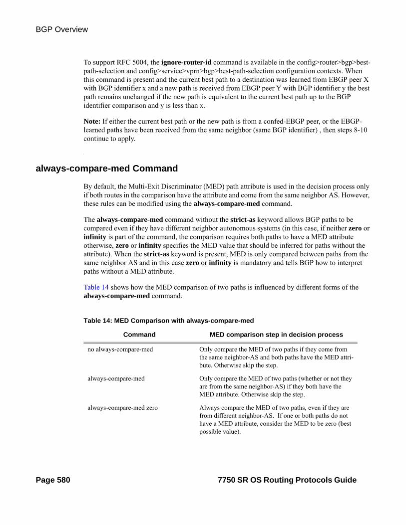
BGP Overview
To support RFC 5004, the ignore-router-id command is available in the config>router>bgp>best-path-selection and config>service>vprn>bgp>best-path-selection configuration contexts. When this command is present and the current best path to a destination was learned from EBGP peer X with BGP identifier x and a new path is received from EBGP peer Y with BGP identifier y the best path remains unchanged if the new path is equivalent to the current best path up to the BGP identifier comparison and y is less than x.
Note: If either the current best path or the new path is from a confed-EBGP peer, or the EBGP-learned paths have been received from the same neighbor (same BGP identifier) , then steps 8-10 continue to apply.
always-compare-med Command
By default, the Multi-Exit Discriminator (MED) path attribute is used in the decision process only if both routes in the comparison have the attribute and come from the same neighbor AS. However, these rules can be modified using the always-compare-med command.
The always-compare-med command without the strict-as keyword allows BGP paths to be compared even if they have different neighbor autonomous systems (in this case, if neither zero or infinity is part of the command, the comparison requires both paths to have a MED attribute otherwise, zero or infinity specifies the MED value that should be inferred for paths without the attribute). When the strict-as keyword is present, MED is only compared between paths from the same neighbor AS and in this case zero or infinity is mandatory and tells BGP how to interpret paths without a MED attribute.
Table 14 shows how the MED comparison of two paths is influenced by different forms of the always-compare-med command.
Table 14: MED Comparison with always-compare-med
Command MED comparison step in decision process
no always-compare-med Only compare the MED of two paths if they come from the same neighbor-AS and both paths have the MED attri-bute. Otherwise skip the step.
always-compare-med Only compare the MED of two paths (whether or not they are from the same neighbor-AS) if they both have the MED attribute. Otherwise skip the step.
always-compare-med zero Always compare the MED of two paths, even if they are from different neighbor-AS. If one or both paths do not have a MED attribute, consider the MED to be zero (best possible value).
Page 580 7750 SR OS Routing Protocols Guide

BGP
Option to Ignore Next-Hop Metric
The ignore-nh-metric command allows the step comparing the distance to the BGP next-hop to be skipped. When this command is present in the config>service>vprn context, it applies to the comparison of two imported BGP-VPN routes. When this command is present in the config>router>bgp context, it applies to the comparison of any two BGP routes received by that instance. And when this command is present in the config>service>vprn>bgp context, it applies to the comparison of two BGP routes learned from VPRN BGP peers (that is, CE peers). In all cases, this option is useful when there are multiple paths for a prefix that are the same in the IGP cost comparison step of the BGP decision process, and the network administrator wants all of them to be used for forwarding (BGP multipath).
always-compare-med infinity Always compare MED of two paths, even if they are from different neighbor-AS. If one or both paths do not have a MED attribute, consider the MED to be infinite (worse possible value).
always-compare-med strict-as zero Only compare the MED of two paths if they come from the same neighbor-AS. If one or both paths do not have a MED attribute, consider the MED to be zero (best possi-ble value).
always-compare-med strict-as infinity Only compare the MED of two paths if they come from the same neighbor-AS. If one or both paths do not have a MED attribute, consider the MED to be infinite (worse possible value).
Table 14: MED Comparison with always-compare-med (Continued)
Command MED comparison step in decision process
7750 SR OS Routing Protocols Guide Page 581

BGP Overview
Page 582 7750 SR OS Routing Protocols Guide

BGP
Best External
Best-external is a BGP enhancement that allows a BGP speaker to advertise to its IBGP peers its best “external” route for a prefix/NLRI even when its best overall route for the prefix/NLRI is an “internal” route. This is not possible in a “normal” BGP configuration because the base BGP specification prevents a BGP speaker from advertising a non-best route for a destination.
In certain topologies, best-external can improve convergence times, reduce route oscillation, and allow better loadsharing. This is achieved because routers internal to the AS have knowledge of more exit paths from the AS. Enabling Add-paths on border routers of the AS can achieve a similar result, but Add-paths introduces NLRI format changes that must be supported by BGP peers of the border router, and therefore has more interoperability constraints than best-external (which requires no messaging changes).
Enabling the best-external feature is supported only at the config>router>bgp level. This feature can be enabled/disabled on a per address family basis, with IPv4 and IPv6 as the only options supported initially. Enabling best-external for IPv4 causes the new advertisement rules to apply to both regular IPv4 unicast routes as well as labeled-IPv4 (SAFI4) routes. Similarly, enabling best-external for IPv6 causes the new advertisement rules to apply to both regular IPv6 unicast routes as well as labeled-IPv6 (SAFI4) routes.
The advertise-external command cannot be applied to a route reflector unless client-to-client reflection is disabled (disable-client-reflect in the CLI).
Advertisement Rules with Best External
The advertisement rules when advertise-external is enabled can be summarized as follows:
1. If a router has advertise-external enabled and its best overall route is a route from an IBGP peer then this best route should be advertised to EBGP and confed-EBGP peers, AND the “best external” route should be advertised to IBGP peers. The “best external” route is the one found by running the BGP path selection algorithm on all RIB-IN paths except for those learned from the IBGP peers.
2. If a router has advertise-external enabled and its best overall route is a route from an EBGP peer then this best route should be advertised to EBGP, confed-EBGP, and IBGP peers.
3. If a router has advertise-external enabled and its best overall route is a route from a confed-EBGP peer in member AS X then this best route should be advertised to EBGP, IBGP peers and confed-EBGP peers in a member AS ≠ X AND the “best internal” route should be advertised to confed-EBGP peers in member AS X. The “best internal” route is the one found by running the BGP path selection algorithm on all RIB-IN paths except for those learned from member AS X.
7750 SR OS Routing Protocols Guide Page 583

BGP Overview
Figure 25: BGP Update Message with Path Identifier for IPv4 NLRI
Add-paths are only supported by the base router BGP instance and the EBGP and IBGP sessions it forms with other add-paths capable peers. The ability to send and receive multiple paths per prefix from to and an add-paths peer is configurable per family, with the supported families being:
BGP Add-Path
Add-paths is a BGP enhancement that allows a BGP router to advertise multiple distinct paths for the same prefix/NLRI. This provides a number of potential benefits, including reduced routing churn, faster convergence, and better loadsharing.
In order for router A to receive multiple paths per NLRI from peer B, for a particular address family, the BGP capabilities advertisement during session setup indicate that peer B wants to send multiple paths for this address family and router A is willing to receive multiple paths for the address family. Refer to draft-ietf-idr-add-paths-04.txt for details of the add-paths capabilities advertisement.
When the add-paths receive capability for an address family that has been negotiated with a peer, all advertisements and withdrawals of NLRI within that address family by that peer includes a path identifier, as described in draft-ietf-idr-add-paths-04.txt.
The path identifiers have no significance to the receiving peer. If the combination of NLRI and path identifier in an advertisement from a peer is unique (does not match an existing route in the RIB-IN from that peer) then the route is added to the RIB-IN. If the combination of NLRI and path identifier in a received advertisement is the same as an existing route in the RIB-IN from the peer then the new route replaces the existing one. If the combination of NLRI and path identifier in a received withdrawal matches an existing route in the RIB-IN from the peer then that route is removed from the RIB-IN. An UPDATE message carrying an IPv4 NLRI with a path identifier is shown in Figure 25.
Length (1 octet)
Prefix (variable)
Length (1 octet)
Prefix (variable)
Length (1 octet)Prefix (variable)
Length (1 octet)
Prefix (variable)
Path identifier (4 octets)Length (1 octet)
Prefix (variable)
Withdrawn Routes Length (2 octets)
Withdrawn Routes (variable)
Total Path Attribute Length (2 octets)Path Attributes (variable)
Path identifier (4 octets)
Length (1 octet)
Prefix (variable)
Path identifier (4 octets)
Length (1 octet)Prefix (variable)
Path identifier (4 octets)Length (1 octet)
Prefix (variable)
OSSG652
Route 1
Route 2
Route 3
Route 4
New
Page 584 7750 SR OS Routing Protocols Guide

BGP
• IPv4 (including labeled IPv4 routes)
• VPN-IPv4
• IPv6 (including labeled IPv6 routes)
• VPN-IPv6
7750 SR OS Routing Protocols Guide Page 585

BGP Overview
Sending Multiple Paths per Prefix to Add-Paths Peers
Path Selection Mode and Parameters
The RIB-IN may have multiple paths for a prefix D. The path selection mode refers to the algorithm used to decide which of these paths to advertise to an add-paths peer. In the current implementation, SR supports only one path selection algorithm –essentially the Add-N algorithm described in draft-ietf-idr-add-paths-guidelines-00.txt, Best Practices for Advertisement of Multiple Paths in BGP. The Add-N algorithm implemented in SROS selects, as candidates for advertisement, the N best overall paths for each prefix, regardless of path type (internal vs. external), degree of difference between the paths or use in forwarding. If this set of N best overall paths includes multiple paths with the same BGP NEXT_HOP only the best route with a particular NEXT_HOP is advertised and the others are suppressed.
In the SROS implementation N is configurable, per address-family, at the BGP instance, group and neighbor levels; N has a minimum value of 1 and a maximum value of 16. For peer P belonging to group G the path selection parameters are based on the neighbor configuration for P else the group configuration for G else the BGP instance configuration.
When add- path is enabled for the VPN-IPv4 (or VPN-IPv6) address family in the base router BGP context only VPN-IP routes in the base router BGP RIB-IN are considered for advertisement to Add-Path peers, if a VPRN’s best route to a destination is a bgp-vpn route imported from the base router and it’s next-best route is a CE-learned BGP route that would be accepted by the VPRN’s VRF export policy this next-best route is not advertised, regardless of the base router’s Add-Path configuration.
Routing Policy
BGP and VRF export policies are applied after path selection is performed. If add-paths is configured to send up to N paths to peer P and an export policy prevents X of the N best paths for prefix D from being advertised to P then only the remaining N-X best paths are sent.
BGP Route Advertisement Rules
Add-paths allows non-best paths to be advertised to a peer but it still complies with basic BGP advertisement rules such as the IBGP split horizon rule: a route learned from an IBGP neighbor cannot be re-advertised to another IBGP neighbor unless the router is configured as a route reflector.
If add-paths is configured to send up to N paths to peer P and X of the N best paths for D cannot be advertised to P due to route advertisement rules then only the remaining N-X routes are advertised.
Page 586 7750 SR OS Routing Protocols Guide
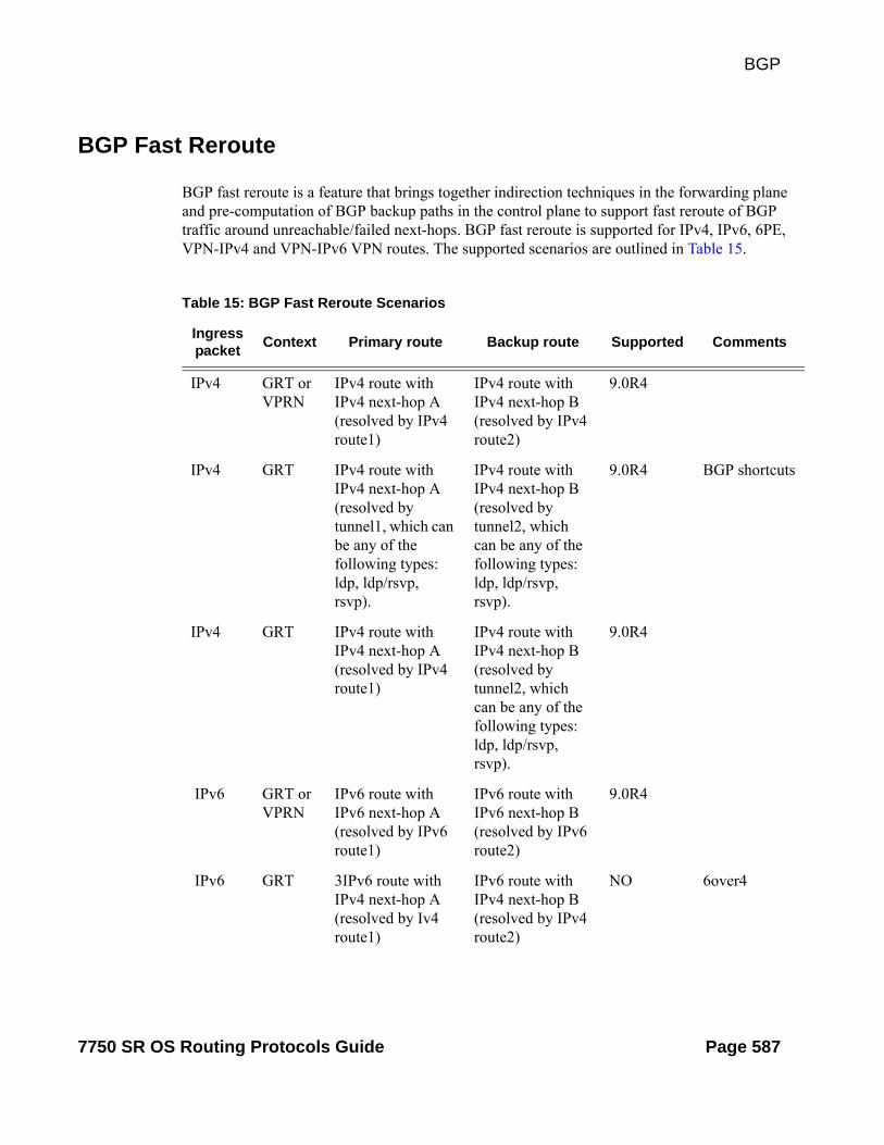
BGP
BGP Fast Reroute
BGP fast reroute is a feature that brings together indirection techniques in the forwarding plane and pre-computation of BGP backup paths in the control plane to support fast reroute of BGP traffic around unreachable/failed next-hops. BGP fast reroute is supported for IPv4, IPv6, 6PE, VPN-IPv4 and VPN-IPv6 VPN routes. The supported scenarios are outlined in Table 15.
Table 15: BGP Fast Reroute Scenarios
Ingress packet
Context Primary route Backup route Supported Comments
IPv4 GRT or VPRN
IPv4 route with IPv4 next-hop A (resolved by IPv4 route1)
IPv4 route with IPv4 next-hop B (resolved by IPv4 route2)
9.0R4
IPv4 GRT IPv4 route with IPv4 next-hop A (resolved by tunnel1, which can be any of the following types: ldp, ldp/rsvp, rsvp).
IPv4 route with IPv4 next-hop B (resolved by tunnel2, which can be any of the following types: ldp, ldp/rsvp, rsvp).
9.0R4 BGP shortcuts
IPv4 GRT IPv4 route with IPv4 next-hop A (resolved by IPv4 route1)
IPv4 route with IPv4 next-hop B (resolved by tunnel2, which can be any of the following types: ldp, ldp/rsvp, rsvp).
9.0R4
IPv6 GRT or VPRN
IPv6 route with IPv6 next-hop A (resolved by IPv6 route1)
IPv6 route with IPv6 next-hop B (resolved by IPv6 route2)
9.0R4
IPv6 GRT 3IPv6 route with IPv4 next-hop A (resolved by Iv4 route1)
IPv6 route with IPv4 next-hop B (resolved by IPv4 route2)
NO 6over4
7750 SR OS Routing Protocols Guide Page 587

BGP Overview
IPv6 GRT Labeled-IPv6 (6PE) route with IPv4-mapped IPv6 next-hop A (resolved by tunnel1, which can be any of the following types: ldp, ldp/rsvp).
Labeled-IPv6 (6PE) route with IPv4-mapped IPv6 next-hop B (resolved by tunnel2, which can be any of the following types: ldp, ldp/rsvp).
9.0R4 For the best performance the primary and backup next-hops must advertise the same label value with all 6PE routes (e.g. IPv6 explicit null).
IPv6 GRT Labeled-IPv6 (6PE) route with IPv4-mapped IPv6 next-hop A (resolved by tunnel1, which can be any of the following types: ldp, ldp/rsvp).
IPv6 route with IPv6 next-hop B (resolved by IPv6 route2)
9.0R4
MPLS Egress IP VPN PE
IPv4 route with CE next-hop A (resolved by IPv4 route1)
IPv4 route with CE next-hop B (resolved by IPv4 route2)
9.0R4 VPRN label mode must be VRF.
MPLS Egress IP VPN PE
IPv6 route with CE next-hop A (resolved by IPv6 route1)
IPv6 route with CE next-hop B (resolved by IPv6 route2)
9.0R4 VPRN label mode must be VRF.
Table 15: BGP Fast Reroute Scenarios (Continued)
Ingress packet
Context Primary route Backup route Supported Comments
Page 588 7750 SR OS Routing Protocols Guide

BGP
IPv4 Ingress IP VPN PE
VPN-IPv4 route with RD x, PE next-hop A (resolved by tunnel1, which can be any of the following types: gre, ldp, ldp/rsvp, rsvp, bgp/ldp, or bgp/rsvp).
VPN-IPv4 route with RD y, PE next-hop B (resolved by tunnel2, which can be any of the following types: gre, ldp, ldp/rsvp, rsvp, bgp/ldp, or bgp/rsvp).
10.0R1 RD x and RD y can be the same or different. For the best performance the primary and backup next-hops must advertise the same VPRN label value with all routes (e.g. per VRF label).
IPv6 Ingress IP VPN PE
VPN-IPv6 route with RD x, PE next-hop A (resolved by tunnel1, which can be any of the following types: gre, ldp, ldp/rsvp, rsvp, bgp/ldp, or bgp/rsvp).
VPN-IPv6 route with RD y, PE next-hop B (resolved by tunnel2, which can be any of the following types: gre, ldp, ldp/rsvp, rsvp, bgp/ldp, or bgp/rsvp).
10.0R1 RD x and RD y can be the same or different. For the best performance the primary and backup next-hops must advertise the same VPRN label value with all routes (e.g. per VRF label).
Table 15: BGP Fast Reroute Scenarios (Continued)
Ingress packet
Context Primary route Backup route Supported Comments
7750 SR OS Routing Protocols Guide Page 589

BGP Overview
MPLS Egress IP VPN
PE
IPv4 route with CE next-hop A
(resolved by IPv4 route1)
VPN-IPv4 route with RD y, PE next-hop B (resolved by tunnel2, which can be any of the following types: gre, ldp, ldp/rsvp, rsvp, bgp/ldp, or bgp/rsvp).
10.0R1 VPRN label mode must be VRF. VPRN must export its VPN-IP routes with RD ≠ y. For the best performance the backup next-hop must advertise the same VPRN label value with all routes (e.g. per VRF label).
MPLS Egress IP VPN
PE
IPv6 route with CE next-hop A
(resolved by IPv6 route1)
VPN-IPv6 route with RD y, PE next-hop B (resolved by tunnel2, which can be any of the following types: gre, ldp, ldp/rsvp, rsvp, bgp/ldp, or bgp/rsvp).
10.0R1 VPRN label mode must be VRF. VPRN must export its VPN-IP routes with RD ≠ y. For the best performance the backup next-hop must advertise the same VPRN label value with all routes (e.g. per VRF label).
Table 15: BGP Fast Reroute Scenarios (Continued)
Ingress packet
Context Primary route Backup route Supported Comments
Page 590 7750 SR OS Routing Protocols Guide
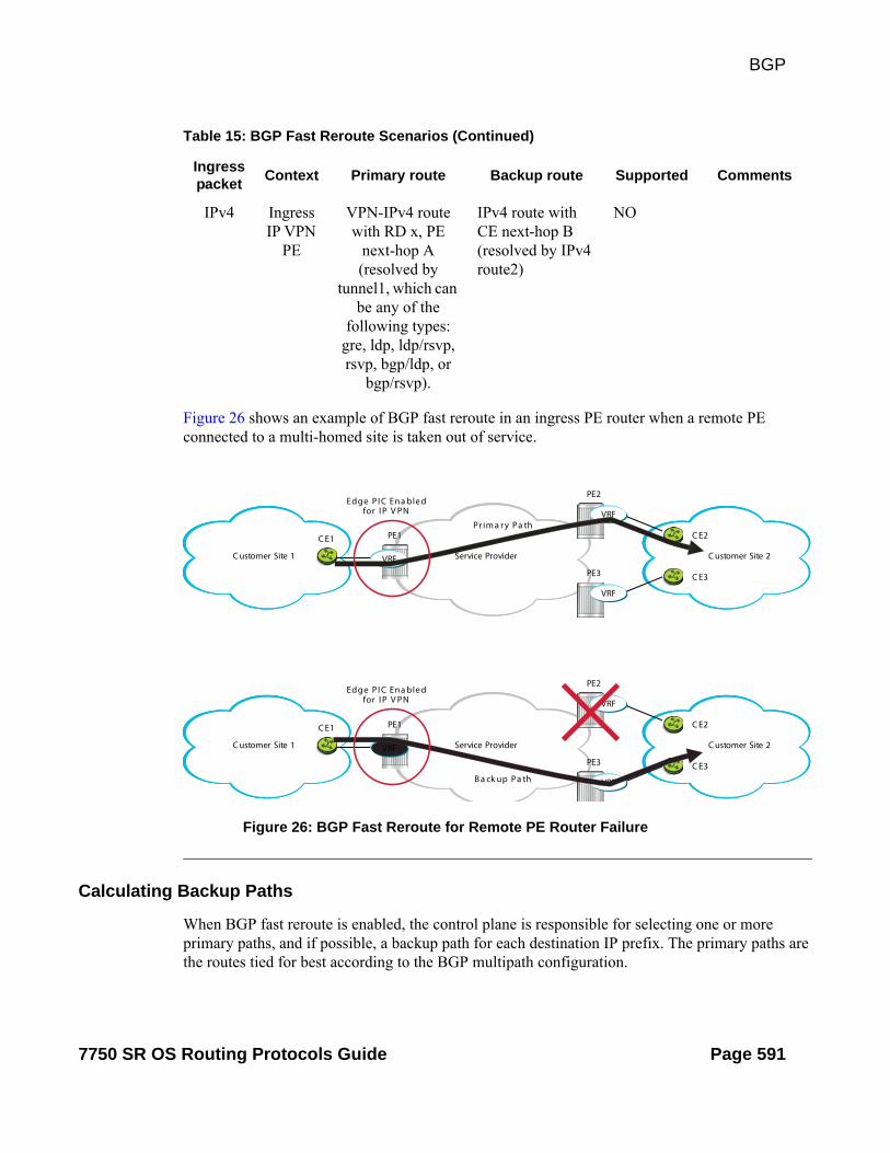
BGP
Figure 26: BGP Fast Reroute for Remote PE Router Failure
Figure 26 shows an example of BGP fast reroute in an ingress PE router when a remote PE connected to a multi-homed site is taken out of service.
C ustomer Site 2C ustomer Site 1
C E1 PE1
PE2
PE3
VRF
VRF
Pr im a r y Pa th
Service Provider
C E3
VRF
C E2
C ustomer Site 2C ustomer Site 1
C E1 PE1
PE2
PE3
VRF
VRF
Service Provider
C E3
VRF
C E2
Edge PI C Ena ble d for I P V PN
Edge PI C Ena ble d for I P V PN
B a ck up Pa th
Calculating Backup Paths
When BGP fast reroute is enabled, the control plane is responsible for selecting one or more primary paths, and if possible, a backup path for each destination IP prefix. The primary paths are the routes tied for best according to the BGP multipath configuration.
IPv4 Ingress IP VPN
PE
VPN-IPv4 route with RD x, PE
next-hop A (resolved by
tunnel1, which can be any of the
following types: gre, ldp, ldp/rsvp, rsvp, bgp/ldp, or
bgp/rsvp).
IPv4 route with CE next-hop B (resolved by IPv4 route2)
NO
Table 15: BGP Fast Reroute Scenarios (Continued)
Ingress packet
Context Primary route Backup route Supported Comments
7750 SR OS Routing Protocols Guide Page 591

BGP Overview
The backup path is the single best path remaining after the primary ECMP paths and any paths with the same BGP next-hops as these paths have been removed.
Sending Failure Notifications to the IOM
When BGP fast reroute is enabled, the IOM reroutes traffic onto a backup path based on input from BGP. When BGP decides that a primary path is no longer usable, it sends message to the IOM indicating that the corresponding BGP next-hop is unreachable/ unresolved. If this results in all of the primary paths being unresolved, the IOM switches affected traffic to the backup path.
These are some of events that can trigger the sending of a next-hop down message to the IOM:
• TCP session closed with the neighbor.
• BGP session terminated with the neighbor.
• Fast-external failover is enabled and the interface with a single-hop EBGP neighbor goes down.
• Peer tracking is enabled and there is no route to the peer address of the neighbor.
• BFD is enabled with a neighbor and the BFD session goes down.
• There is no active IP route that matches the BGP next-hop address.
Page 592 7750 SR OS Routing Protocols Guide

BGP
Command Interactions and Dependencies
This section highlights the BGP command interactions and dependencies which are important for configuration or operational maintenance of 7750 SR routers. Topics covered in this section are:
• Changing the Autonomous System Number on page 593
• Changing a Confederation Number on page 594
• Changing the Router ID at the Configuration Level on page 594
• Changing the Local AS Number on page 594
• Hold Time and Keep Alive Timer Dependencies on page 595
• Import and Export Route Policies on page 596
• Route Damping and Route Policies on page 596
Note that this information can be found in the BGP Command Reference on page 629 which provides detailed descriptions of the configuration commands.
Changing the Autonomous System Number
If the AS number is changed on a router with an active BGP instance (that is at the config>router>level), the new AS number will not be used until the BGP instance is restarted either by administratively disabling and enabling the BGP instance or by rebooting the system with the new configuration.
7750 SR OS Routing Protocols Guide Page 593

BGP Overview
Changing the Local AS Number
Changing the local AS of an active BGP instance:
• At the global level causes the BGP instance to restart with the new local AS number.
• At the group level causes BGP to re-establish the peer relationships with all peers in the group with the new local AS number.
• At the neighbor level causes BGP to re-establish the peer relationship with the new local AS number.
Changing a Confederation Number
Changing the a confederation value on an active BGP instance will not restart the protocol. The change will take affect when the BGP protocol is (re) initialized.
Changing the Router ID at the Configuration Level
If you configure a new router ID in the config>router context, protocols are not automatically restarted with the new router ID. The next time a protocol is (re) initialized the new router ID is used. An interim period of time can occur when different protocols use different router IDs.
Page 594 7750 SR OS Routing Protocols Guide

BGP
Hold Time and Keep Alive Timer Dependencies
The BGP hold time specifies the maximum time BGP will wait between successive messages (either keep alive or update) from its peer, before closing the connection. This configuration parameter can be set at three levels. The most specific value is used.
• Global level — applies to all peers
• Group level — applies to all peers in group
• Neighbor level — only applies to specified peer
Although the keep alive time can be user specified, the configured keep alive timer is overridden by the value of hold time under the following circumstances:
• If the hold time specified is less than the configured keep alive time, then the operational keep alive time is set to one third of the specified hold time; the configured keep alive time is unchanged.
• If the hold time is set to zero, then the operational value of the keep alive time is set to zero; the configured keep alive time is unchanged. This means that the connection with the peer will be up permanently and no keep alive packets are sent to the peer.
If the hold time or keep alive values are changed, the changed timer values take effect when the new peering relationship is established. Changing the values cause the peerings to restart. The changed timer values are used when re-negotiating the peer relationship.
7750 SR OS Routing Protocols Guide Page 595

BGP Overview
Import and Export Route Policies
Import and export route policy statements are specified for BGP on the global, group, and neighbor level. Up to five unique policy statement names can be specified in the command line per level. The most specific command is applied to the peer. Defining the policy statement name is not required before being applied. Policy statements are evaluated in the order in which they are specified within the command context.
NOTE: You can use the keep option for VPRN related routes to remove the need to send route refresh messages; see mp-bgp-keep on page 666. When enabled, BGP maintains all VPRN related routes descriptive information.
The import and export policies configured on different levels are not cumulative. The most specific value is used. An import or export policy command specified on the neighbor level takes precedence over the same command specified on the group or global level. An import or export policy command specified on the group level takes precedence over the same command specified on the global level.
Route Damping and Route Policies
To prevent BGP systems from sending excessive route changes to peers, BGP route damping can be implemented. Damping can reduce the number of update messages sent between BGP peers, to reduce the load on peers, without adversely affecting the route convergence time for stable routes.
The damping profile defined in the policy statement is applied to control route damping parameters. Route damping characteristics are specified in a route damping profile and are referenced in the action for the policy statement or in the action for a policy entry. Damping can be specified at the global, group, or neighbor level with the most specific command applied to the peer.
AS Override
AS Override simplifies the use of the same AS number (ASN) across multiple VPRN sites.
The AS Override feature can be used in VPRN scenarios where a customer is running BGP as the PE-CE protocol and some or all of the CE locations are in the same Autonomous System (AS). With normal BGP, two sites in the same AS would not be able to reach each other directly since there is an apparent loop in the ASPATH.
With AS Override enabled on an egress eBGP session, the PE rewrites the customer ASN in the ASPATH with the VPRN AS number as the route is advertised to the CE.
Page 596 7750 SR OS Routing Protocols Guide

BGP
BGP FlowSpec
FlowSpec is a standardized method (defined in RFC 5575) for using BGP to distribute traffic flow specifications (flow routes) throughout a network. A flow route carries a description of a flow in terms of packet header fields such as source IP address, destination IP address, or TCP/UDP port number and indicates (through a community attribute) an action to take on packets matching the flow. The primary application for Flowspec is DDoS mitigation.
Flowspec is supported by SROS only by the base router BGP instance and only for IPv4 packets. To exchange IPv4 FlowSpec routes with a BGP peer, the MP-BGP capability for AFI 1 and SAFI 133 must be negotiated when the session is established. The flow-ipv4 keyword must be part of the family command (at the BGP instance, group, or neighbor level) for this capability negotiation to occur.
The NLRI of an IPv4 flow route can contain one or more of the subcomponents shown in Table 16.
Table 16: Subcomponents of IPv4 Flow Route NLRI
Subcomponent Name [Type]
Value Encoding SROS Support
Destination IPv4 Prefix [1] Prefix length, prefix Yes
Source IPv4 Prefix [2] Prefix length, prefix Yes
IP Protocol [3] One or more (operator, value) pairs Partial. No support for multiple values other than “TCP or UDP”.
Port [4] One or more (operator, value) pairs No
Destination Port [5] One or more (operator, value) pairs Partial. No support for multiple ranges.
Source Port [6] One or more (operator, value) pairs Partial. No support for multiple ranges.
ICMP Type [7] One or more (operator, value) pairs Partial. Only a single value is supported.
ICMP Code [8] One or more (operator, value) pairs Partial. Only a single value is supported.
TCP Flags [9] One or more (operator, bitmask) pairs
Partial. Only SYN and ACK flags can be matched.
Packet Length [10] One or more (operator, value) pairs No
DSCP [11] One or more (operator, value) pairs Partial. Only a single value is supported.
7750 SR OS Routing Protocols Guide Page 597

BGP Overview
Table 17 summarizes the actions that may be associated with an IPv4 flow route and how each type of action is encoded.
Table 17: IPv4 Flowspec Actions
Action Encoding SROS Support
Rate Limit Extended community type 0x8006 Partial. Only rate=0 is supported.
Sample/Log Extended community type 0x8007. S-bit Yes
Next Entry Extended community type 0x8007. T-bit No
Redirect to VRF Extended community type 0x8008. Yes
Mark Traffic Class Extended community type 0x8009. No
Note: An IPv4 flow route cannot have more than one instance of a flowspec extended community in the range 0x8006-0x8009. If it has more than one instance, a log/trap is generated and no filter entry is installed for the flow route.
Validating and Importing Received IPv6 Flow Routes into the Routing Table
IPv4 flow routes received from a BGP peer must be validated before being considered for import into the routing table. An IPv4 flow route is considered invalid if:
1. The flow route is received from an EBGP peer and the left most AS number in the AS_PATH attribute does not equal the peer’s AS number (from the group/neighbor configuration).
2. The flowspec-validate command is enabled, the flow route has a destination prefix subcomponent D, and the flow route was received from a peer P that did not advertise the best IP route to D and all more-specific prefixes.
After received flow routes are validated they are processed by the relevant import policies.
Note: An IPv4 flow route never matches a prefix entry in a prefix-list, even if the destination IPv4 prefix subcomponent or the source IPv4 prefix subcomponent of the NLRI is a match.
Fragment [12] One or more (operator, bitmask) pairs
Partial. No support for matching DF bit, first-fragment or last-fragment.
Table 16: Subcomponents of IPv4 Flow Route NLRI (Continued)
Subcomponent Name [Type]
Value Encoding SROS Support
Page 598 7750 SR OS Routing Protocols Guide

BGP
If the router receives the exact same IPv4 flow route NLRI from multiple peers then the router selects one best path from among all received paths. The best path selection follows the existing implementation (used for all other BGP NLRI). Step 1 of the algorithm eliminates invalid routes and for IPv4 flow routes. This includes routes that were required to meet the validation checks described by the standard but did not. For each NLRI, the route with the best path is:
• Installed in the LOC-RIB.
• Propagated to BGP peers, depending on export policies.
• Used if possible to create an IPv4 filter entry.
Propagating IPv4 Flow Routes to BGP Neighbors
When the base router BGP instance installs an IPv4 flow route into its LOC-RIB the default export policy causes it to advertise the flow route to all of its AFI=1/SAFI=133 BGP peers.
User-configured export policies can be used to override the default export policy. Export policy actions do not change the contents of the flow route NLRI in any way.
Using IPv4 Flow Routes to Create Dynamic IPv4 Filter Entries
When the base router BGP instance installs an IPv4 flow route into its LOC-RIB, the system attempts to construct an ipv4-filter entry from the NLRI contents and the action(s) encoded in the UPDATE message. If successful, the filter entry is added to the system-created ‘’fSpec-1” IPv4 filter policy that internally has an identifier of 16777217. This “fSpec-1” filter policy is applied to the following:
• Ingress IPv4 traffic on a network interface, if the config>router>interface >ingress configuration includes the keyword flowspec.
• Ingress IPv4 traffic on an IES SAP interface, if the config>service>ies>interface>sap>ingress configuration includes the keyword flowspec.
• Ingress IPv4 traffic on an IES spoke SDP interface, if the config>service>ies>interface>spoke-sdp>ingress configuration includes the keyword flowspec.
A user-defined IPv4 filter policy can be applied to a base router interface that has IPv4 flow-spec enabled. When an interface has both a user-defined IPv4 filter policy and the system-created ‘fSpec-1’ IPv4 filter policy, the IPv4 filter rules are installed in the following order:
1. User-defined IPv4 filter entries (in ascending order of entry IDs).
7750 SR OS Routing Protocols Guide Page 599

BGP Overview
2. IPv4 flowspec entries (in order, determined by comparison of the NLRI described in RFC 5575).
3. User-defined IPv4 filter default action.
Page 600 7750 SR OS Routing Protocols Guide
BGP
TTL Security for BGP and LDP
The BGP TTL Security Hack (BTSH) was originally designed to protect the BGP infrastructure from CPU utilization-based attacks. It is derived on the fact that the vast majority of ISP eBGP peerings are established between adjacent routers. Since TTL spoofing is considered nearly impossible, a mechanism based on an expected TTL value can provide a simple and reasonably robust defense from infrastructure attacks based on forged BGP packets.
While TSH is most effective in protecting directly connected peers, it can also provide a lower level of protection to multi-hop sessions. When a multi-hop BGP session is required, the expected TTL value can be set to 255 minus the configured range-of-hops. This approach can provide a qualitatively lower degree of security for BGP (such as a DoS attack could, theoretically, be launched by compromising a box in the path). However, BTSH will catch a vast majority of observed distributed DoS (DDoS) attacks against eBGP. For further information, refer to draft-gill-btsh-xx.txt, The BGP TTL Security Hack (BTSH).
TSH can be used to protect LDP peering sessions as well. For details, see draft-chen-ldp-ttl-xx.txt, TTL-Based Security Option for LDP Hello Message.
The TSH implementation supports the ability to configure TTL security per BGP/LDP peer and evaluate (in hardware) the incoming TTL value against the configured TTL value. If the incoming TTL value is less than the configured TTL value, the packets are discarded and a log is generated.
7750 SR OS Routing Protocols Guide Page 601

BGP Configuration Process Overview
Figure 27: BGP Configuration and Implementation Flow
BGP Configuration Process Overview
Figure 27 displays the process to provision basic BGP parameters.
TURN UP
START
CONFIGURE GLOBAL ROUTER PARAMETERS
CONFIGURE BGP GROUP PARAMETERS
CONFIGURE BGP NEIGHBOR PARAMETERS
- ASSIGN AUTONOMOUS SYSTEM NUMBER- CONFIGURE ROUTER ID
- CONFIGURE CONFEDERATIONS (optional)
Page 602 7750 SR OS Routing Protocols Guide

BGP
Configuration Notes
This section describes BGP configuration caveats.
General
• Before BGP can be configured, the router ID and autonomous system should be configured.
• BGP must be added to the router configuration. There are no default BGP instances on a 7750 SR.
BGP Defaults
The following list summarizes the BGP configuration defaults:
• By default, the 7750 SR is not assigned to an AS.
• A BGP instance is created in the administratively enabled state.
• A BGP group is created in the administratively enabled state.
• A BGP neighbor is created in the administratively enabled state.
• No BGP router ID is specified. If no BGP router ID is specified, BGP uses the router system interface address.
• The 7750 SR OS BGP timer defaults are generally the values recommended in IETF drafts and RFCs (see BGP MIB Notes on page 604)
• If no import route policy statements are specified, then all BGP routes are accepted.
• If no export route policy statements specified, then all best and used BGP routes are advertised and non-BGP routes are not advertised.
7750 SR OS Routing Protocols Guide Page 603

Configuration Notes
BGP MIB Notes
The 7750 SR OS implementation of the RFC 1657 MIB variables listed in Table 18 differs from the IETF MIB specification.
Table 18: TiMOS and IETF MIB Variations
MIB Variable Description RFC 1657 Allowed Values
7750 SR OSAllowed Values
bgpPeerMinASOrigina-tionInterval
Time interval in seconds for the MinASOriginationInterval timer. The suggested value for this timer is 15 seconds.
1 — 65535 2 — 255
bgpPeerMinRouteAdver-tisementInterval
Time interval in seconds for the MinRouteAdvertisementInterval timer. The suggested value for this timer is 30.
1 — 65535 a
a.A value of 0 is supported when the rapid-update command is applied to an address family that supports it.
1 — 255
If SNMP is used to set a value of X to the MIB variable in Table 19, there are three possible results:
Table 19: MIB Variable with SNMP
Condition Result
X is within IETF MIB valuesandX is within 7750 SR OS values
SNMP set operation does not return an errorMIB variable set to X
X is within IETF MIB valuesandX is outside 7750 SR OS values
SNMP set operation does not return an errorMIB variable set to “nearest” 7750 SR OS supported value (e.g. 7750 SR OS range is 2 - 255 and X = 65535, MIB variable will be set to 255)Log message generated
X is outside IETF MIB valuesandX is outside 7750 SR OS values
SNMP set operation returns an error
Page 604 7750 SR OS Routing Protocols Guide
BGP
When the value set using SNMP is within the IETF allowed values and outside the TiMOS values as specified in Table 18 and Table 19, a log message is generated. The log messages that display are similar to the following log messages:
Sample Log Message for setting bgpPeerMinASOriginationInterval to 65535
576 2006/11/12 19:45:48 [Snmpd] BGP-4-bgpVariableRangeViolation: Trying to set bgpPeerMinASOrigInt to 65535 - valid range is [2-255] - setting to 255
Sample Log Message for setting bgpPeerMinASOriginationInterval to 1
594 2006/11/12 19:48:05 [Snmpd] BGP-4-bgpVariableRangeViolation: Trying to set bgpPeerMinASOrigInt to 1 - valid range is [2-255] - setting to 2
Sample Log Message for setting bgpPeerMinRouteAdvertisementInterval to 256
535 2006/11/12 19:40:53 [Snmpd] BGP-4-bgpVariableRangeViolation: Trying to set bgpPeerMinRouteAdvInt to 256 - valid range is [2-255] - setting to 255
Sample Log Message for setting bgpPeerMinRouteAdvertisementInterval to 1
566 2006/11/12 19:44:41 [Snmpd] BGP-4-bgpVariableRangeViolation: Trying to set bgpPeerMinRouteAdvInt to 1 - valid range is [2-255] - setting to 2
7750 SR OS Routing Protocols Guide Page 605

Configuration Notes
Page 606 7750 SR OS Routing Protocols Guide

BGP
Configuring BGP with CLI
This section provides information to configure BGP using the command line interface.
Topics in this section include:
• BGP Configuration Overview on page 608
Preconfiguration Requirements on page 608
BGP Hierarchy on page 608
Internal and External BGP Configurations on page 608
BGP Confederations on page 615
BGP Route Reflectors on page 617
• Basic BGP Configuration on page 610
• Common Configuration Tasks on page 612
Creating an Autonomous System on page 613
Configuring a Router ID on page 614
BGP Components on page 619
Configuring Group Attributes on page 620
Configuring Neighbor Attributes on page 621
Configuring Route Reflection on page 622
Configuring a Confederation on page 623
• BGP Configuration Management Tasks on page 624
Modifying an AS Number on page 624
Modifying the BGP Router ID on page 625
Deleting a Neighbor on page 627
Deleting Groups on page 628
7750 SR OS Routing Protocols Guide Page 607

BGP Configuration Overview
BGP Configuration Overview
Preconfiguration Requirements
Before BGP can be implemented, the following entities must be configured:
• The autonomous system (AS) number for the router.
An AS number is a globally unique value which associates a router to a specific autonomous system. This number is used to exchange exterior routing information with neighboring ASs and as an identifier of the AS itself. Each router participating in BGP must have an AS number specified.
In order to implement BGP, the AS number must be specified in the config>router context.
• Router ID — The router ID is the IP address of the local router. The router ID identifies a packet’s origin. The router ID must be a valid host address.
BGP Hierarchy
BGP is configured in the config>router>bgp context. Three hierarchical levels are included in BGP configurations:
• Global level
• Group level
• Neighbor level
Commands and parameters configured on the global level are inherited to the group and neighbor levels although parameters configured on the group and neighbor levels take precedence over global configurations.
Internal and External BGP Configurations
A BGP system is comprised of ASs which share network reachability information. Network reachability information is shared with adjacent BGP peers. BGP supports two types of routing information exchanges:
• External BGP (EBGP) is used between ASs.
Page 608 7750 SR OS Routing Protocols Guide

BGP
EBGP speakers peer to different ASs and typically share a subnet. In an external group, the next hop is dependent upon the interface shared between the external peer and the specific neighbor. The multihop command must be specified if an EBGP peer is more than one hop away from the local router.
• Internal BGP (IBGP) is used within an AS.
IBGP peers belong to the same AS and typically does not share a subnet. Neighbors do not have to be directly connected to each other. Since IBGP peers are not required to be directly connected, IBGP uses the IGP path (the IP next-hop learned from the IGP) to reach an IBGP peer for its peering connection.
7750 SR OS Routing Protocols Guide Page 609

Basic BGP Configuration
Basic BGP Configuration
This section provides information to configure BGP and configuration examples of common configuration tasks. The minimal BGP parameters that need to be configured are:
• An autonomous system number for the router.
• A router ID - Note that if a new or different router ID value is entered in the BGP context, then the new value takes precedence and overwrites the router-level router ID.
• A BGP peer group.
• A BGP neighbor with which to peer.
• A BGP peer-AS that is associated with the above peer.
The BGP configuration commands have three primary configuration levels: bgp for global configurations, group name for BGP group configuration, and neighbor ip-address for BGP neighbor configuration. Within the different levels, many of the configuration commands are repeated. For the repeated commands, the command that is most specific to the neighboring router is in effect, that is, neighbor settings have precedence over group settings which have precedence over BGP global settings.
Following is a sample configuration that includes the above parameters. The other parameters shown below are optional:
info#--------------------------------------------------echo "IP Configuration"#--------------------------------------------------... autonomous-system 200 confederation 300 members 200 400 500 600 router-id 10.10.10.103#--------------------------------------------------...#--------------------------------------------------echo "BGP Configuration"#-------------------------------------------------- bgp graceful-restart exit cluster 0.0.0.100 export "direct2bgp" router-id 10.0.0.12 group "To_AS_10000" connect-retry 20 hold-time 90 keepalive 30 local-preference 100 remove-private peer-as 10000 neighbor 10.0.0.8 description "To_Router B - EBGP Peer"
Page 610 7750 SR OS Routing Protocols Guide

BGP
connect-retry 20 hold-time 90 keepalive 30 local-address 10.0.0.12 passive preference 99 peer-as 10000 exit exit group "To_AS_30000" connect-retry 20 hold-time 90 keepalive 30 local-preference 100 remove-private peer-as 30000 neighbor 10.0.3.10 description "To_Router C - EBGP Peer" connect-retry 20 hold-time 90 keepalive 30 peer-as 30000 exit exit group "To_AS_40000" connect-retry 20 hold-time 30 keepalive 30 local-preference 100 peer-as 65206 neighbor 10.0.0.15 description "To_Router E - Sub Confederation AS 65205" connect-retry 20 hold-time 90 keepalive 30 local-address 10.0.0.12 peer-as 65205 exit exit exit#--------------------------------------------------....A:ALA-48>config>router#
7750 SR OS Routing Protocols Guide Page 611

Common Configuration Tasks
Common Configuration Tasks
This section provides a brief overview of the tasks that must be performed to configure BGP and provides the CLI commands. In order to enable BGP, one AS must be configured and at least one group must be configured which includes neighbor (system or IP address) and peering information (AS number).
All BGP instances must be explicitly created on each 7750 SR-Series. Once created, BGP is administratively enabled.
Configuration planning is essential to organize ASs and the SRs within the ASs, and determine the internal and external BGP peering.
To configure a basic autonomous system, perform the following tasks:
1. Prepare a plan detailing the autonomous sytem(s), the 7750 SR-Series belonging to each group, group names, and peering connections.
2. Associate each 7750 SR-Series with an autonomous system number.
3. Configure each 7750 SR-Series with a router ID.
4. Associate each 7750 SR-Series with a peer group name.
5. Specify the local IP address that will be used by the group or neighbor when communicating with BGP peers.
6. Specify neighbors.
7. Specify the autonomous system number associated with each neighbor.
Page 612 7750 SR OS Routing Protocols Guide

BGP
Creating an Autonomous System
Before BGP can be configured, the autonomous system must be configured first. In BGP, routing reachability information is exchanged between autonomous systems (ASs). An AS is a group of networks that share routing information. The autonomous-system command associates an autonomous system number to the router being configured. The autonomous-system command is configured in the config>router context.
Use the following CLI syntax to associate a 7750 SR-Series to an autonomous system:
CLI Syntax: config>router# autonomous-system autonomous-system
The 7750 SR-Series series supports 4 bytes AS numbers by default. This means autonomous-system can have any value from 1 to 4294967295. The following example displays autonomous system configuration command usage:
Example: config>router# autonomous-system 100
The following example displays the autonomous system configuration:
ALA-B>config>router# info#------------------------------------------# IP Configuration#------------------------------------------ interface "system" address 10.10.10.104/32 exit interface "to-103" address 10.0.0.104/24 port 1/1/1 exit autonomous-system 100
#------------------------------------------ALA-B>config>router#
7750 SR OS Routing Protocols Guide Page 613

Common Configuration Tasks
Configuring a Router ID
In BGP, routing information is exchanged between autonomous systems. The BGP router ID, expressed like an IPv4 address, uniquely identifies the router. It can be set to be the same as the system interface address.
Note that if a new or different router ID value is entered in the BGP context, then the new router ID value is used instead of the router ID configured on the router level, system interface level, or inherited from the MAC address. The router-level router ID value remains intact. The router ID used by BGP is selected in the following order:
• The routed-id configured under config>router>bgp
• The router-id configured under config>router
• The system interface IPv4 address
• The last 4 bytes of the system MAC address
When configuring a new router ID outside of the config>router>bgp context, BGP is not automatically restarted with the new router ID; the next time BGP is (re) initialized the new router ID is used. An interim period of time can occur when different protocols use different router IDs. To force the new router ID, issue the shutdown and no shutdown commands for BGP or restart the entire router. Use the following CLI syntax to configure the router ID for multiple protocols:
CLI Syntax: config>router# router-id router-id
The following example displays router ID configuration command usage:
Example: config>router# router-id 10.10.10.104
The following example displays the router ID configuration:
ALA-B>config>router# info----------------------------------------------# IP Configuration#------------------------------------------ interface "system" address 10.10.10.104/32 exit interface "to-103" address 10.0.0.104/24 port 1/1/1 exit autonomous-system 100 router-id 10.10.10.104#------------------------------------------...ALA-B>config>router#
Page 614 7750 SR OS Routing Protocols Guide
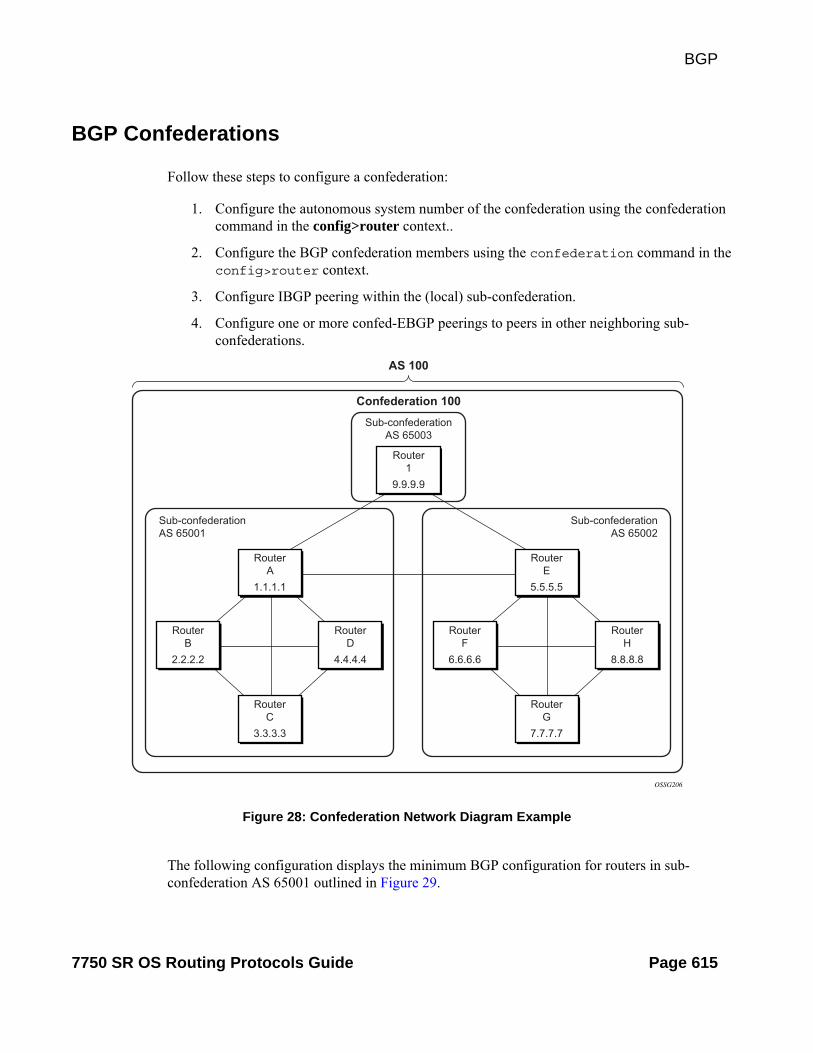
BGP
Figure 28: Confederation Network Diagram Example
The following configuration displays the minimum BGP configuration for routers in sub-confederation AS 65001 outlined in Figure 29.
BGP Confederations
Follow these steps to configure a confederation:
1. Configure the autonomous system number of the confederation using the confederation command in the config>router context..
2. Configure the BGP confederation members using the confederation command in the config>router context.
3. Configure IBGP peering within the (local) sub-confederation.
4. Configure one or more confed-EBGP peerings to peers in other neighboring sub-confederations.
OSSG206
Router1
Sub-confederationAS 65003
Sub-confederationAS 65001
Sub-confederationAS 65002
Confederation 100
AS 100
9.9.9.9
RouterB
2.2.2.2
RouterD
4.4.4.4
RouterA
1.1.1.1
RouterC
3.3.3.3
RouterF
6.6.6.6
RouterH
8.8.8.8
RouterE
5.5.5.5
RouterG
7.7.7.7
7750 SR OS Routing Protocols Guide Page 615

Common Configuration Tasks
ALA-Aconfig router
autonomous-system 65001confederation 100 members 65001 65002 65003bgp
group confed1peer-as 65001neighbor 2.2.2.2exitneighbor 3.3.3.3exitneighbor 4.4.4.4exit
exitgroup external_confed
neighbor 5.5.5.5peer-as 65002
exitneighbor 9.9.9.9
peer-as 65003exit
exitexit
exit
ALA-Dconfig router
autonomous-system 65001confederation 100 members 65001 65002 65003bgp
group confed1peer-as 65001neighbor 1.1.1.1exitneighbor 2.2.2.2exitneighbor 3.3.3.3exit
exitexit
exit
ROUTER 1config router
autonomous-system 65003confederation 100 members 65001 65002 65003bgp
group confed1peer-as 65001neighbor 1.1.1.1exitneighbor 5.5.5.5
peer-as 65002exit
exitexit
exit
Page 616 7750 SR OS Routing Protocols Guide

BGP
Figure 29: Route Reflection Network Diagram Example
BGP Route Reflectors
In a standard BGP configuration, all BGP speakers within an AS must have a full BGP mesh to ensure that all externally learned routes are redistributed through the entire AS. IBGP speakers do not re-advertise routes learned from one IBGP peer to another IBGP peer. If a network grows, scaling issues could emerge because of the full mesh configuration requirement. Route reflection circumvents the full mesh requirement but still maintains the full distribution of external routing information within an AS.
Autonomous systems using route reflection arrange BGP routers into groups called clusters. Each cluster contains at least one route reflector which is responsible for redistributing route updates to all clients. Route reflector clients do not need to maintain a full peering mesh between each other. They only require a peering to the route reflector(s) in their cluster. The route reflectors must maintain a full peering mesh between all non-clients within the AS.
Each route reflector must be assigned a cluster ID and specify which neighbors are clients and which are non-clients to determine which neighbors should receive reflected routes and which should be treated as a standard IBGP peer. Additional configuration is not required for the route reflector besides the typical BGP neighbor parameters.
OSSG273
Router1
Cluster 2.2.2.2Cluster 1.1.1.1
AS 100
9.9.9.9
RouterB
2.2.2.2
RouterD
4.4.4.4
RouterA
1.1.1.1
RouterC
3.3.3.3
RouterF
6.6.6.6
RouterH
8.8.8.8
RouterE
5.5.5.5
RouterG
7.7.7.7
7750 SR OS Routing Protocols Guide Page 617

Common Configuration Tasks
The following configuration displays the minimum BGP configuration for routers in Cluster 1.1.1.1 outlined in Figure 29.
ALA-Aconfig router bgp
group cluster1peer-as 100cluster 1.1.1.1neighbor 2.2.2.2exitneighbor 3.3.3.3exitneighbor 4.4.4.4exit
exitgroup RRs
peer-as 100neighbor 5.5.5.5exitneighbor 9.9.9.9exit
exitexit
ALA-Bconfig router bgp
group cluster1peer-as 100neighbor 1.1.1.1exit
exitexit
ALA-Cconfig router bgp
group cluster1peer-as 100neighbor 1.1.1.1exit
exitexit
ALA-Dconfig router bgp
group cluster1peer-as 100neighbor 1.1.1.1exit
exitexit
Page 618 7750 SR OS Routing Protocols Guide

BGP
BGP Components
Use the CLI syntax displayed below to configure the following BGP attributes:
• BGP Components on page 619
• Configuring Group Attributes on page 620
• Configuring Neighbor Attributes on page 621
• Configuring Route Reflection on page 622
• Configuring a Confederation on page 623
7750 SR OS Routing Protocols Guide Page 619

Common Configuration Tasks
Configuring Group Attributes
A group is a collection of related BGP peers. The group name should be a descriptive name for the group. Follow your group, name, and ID naming conventions for consistency and to help when troubleshooting faults.
All parameters configured for a peer group are applied to the group and are inherited by each peer (neighbor), but a group parameter can be overridden on a specific neighbor-level basis.
The following example displays the BGP group configuration:
ALA-B>config>router>bgp# info----------------------------------------------... group "headquarters1" description "HQ execs" local-address 10.0.0.104 disable-communities standard extended ttl-security 255 exit exit...----------------------------------------------ALA-B>config>router>bgp#
Page 620 7750 SR OS Routing Protocols Guide

BGP
Configuring Neighbor Attributes
After you create a group name and assign options, add neighbors within the same autonomous system to create IBGP connections and/or neighbors in different autonomous systems to create EBGP peers. All parameters configured for the peer group level are applied to each neighbor, but a group parameter can be overridden on a specific neighbor basis.
The following example displays neighbors configured in group “headquarters1”.
ALA-B>config>router>bgp# info----------------------------------------------... group "headquarters1" description "HQ execs" local-address 10.0.0.104 disable-communities standard extended ttl-security 255 neighbor 10.0.0.5 passive peer-as 300 exit neighbor 10.0.0.106 peer-as 100 exit neighbor 17.5.0.2 hold-time 90 keepalive 30 min-as-origination 15 local-preference 170 peer-as 10701 exit neighbor 17.5.1.2 hold-time 90 keepalive 30 min-as-origination 15 local-preference 100 min-route-advertisement 30 preference 170 peer-as 10702 exit exit...----------------------------------------------ALA-B>config>router>bgp#
7750 SR OS Routing Protocols Guide Page 621

Common Configuration Tasks
Configuring Route Reflection
Route reflection can be implemented in autonomous systems with a large internal BGP mesh to reduce the number of IBGP sessions required. One or more routers can be selected to act as focal points for internal BGP sessions. Several BGP speaking routers can peer with a route reflector. A route reflector forms peer connections to other route reflectors. A router assumes the role as a route reflector by configuring the cluster cluster-id command. No other command is required unless you want to disable reflection to specific peers.
If you configure the cluster command at the global level, then all subordinate groups and neighbors are members of the cluster. The route reflector cluster ID is expressed in dotted decimal notation. The ID should be a significant topology-specific value. No other command is required unless you want to disable reflection to specific peers.
If a route reflector client is fully meshed, the disable-client-reflect command can be enabled to stop the route reflector from reflecting redundant route updates to a client.
The following example displays a route reflection configuration:
ALA-B>config>router>bgp# info--------------------------------------------- cluster 0.0.0.100 group "Santa Clara" local-address 10.0.0.103 neighbor 10.0.0.91 peer-as 100 exit neighbor 10.0.0.92 peer-as 100 exit neighbor 10.0.0.93 disable-client-reflect peer-as 100 exit exit---------------------------------------------ALA-B>config>router>bgp#
Page 622 7750 SR OS Routing Protocols Guide

BGP
Configuring a Confederation
Reducing a complicated IBGP mesh can be accomplished by dividing a large autonomous system into smaller autonomous systems. The smaller ASs can be grouped into a confederation. A confederation looks like a single AS to routers outside the confederation. Each confederation is identified by its own (confederation) AS number.
To configure a BGP confederation, you must specify a confederation identifier, an AS number expressed as a decimal integer. The collection of autonomous systems appears as a single autonomous system with the confederation number acting as the “all-inclusive” autonomous system number. Up to 15 members (ASs) can be added to a confederation.
NOTE: The confederation command is configured in the config>router context.
Use the following CLI syntax to configure a confederation:
CLI Syntax: config>router# confederation confed-as-num members member-as-num
When 4-byte AS number support is not disabled on 7750 SR the confederation and any of its members can be assigned an AS number in the range from 1 to 4294967295. The following example displays a confederation configuration command usage:
Example: config>router># confederation 1000 members 100 200 300
The following example displays the confederation configuration:
ALA-B>config>router# info#------------------------------------------# IP Configuration#------------------------------------------ interface "system" address 10.10.10.103/32 exit interface "to-104" shutdown address 10.0.0.103/24 port 1/1/1 exit autonomous-system 100 confederation 1000 members 100 200 300 router-id 10.10.10.103#------------------------------------------ALA-B>config>router#
7750 SR OS Routing Protocols Guide Page 623

Common Configuration Tasks
BGP Configuration Management Tasks
This section discusses the following BGP configuration management tasks:
• Modifying an AS Number on page 624
• Modifying a Confederation Number on page 625
• Modifying the BGP Router ID on page 625
• Modifying the Router-Level Router ID on page 626
• Deleting a Neighbor on page 627
• Deleting Groups on page 628
Modifying an AS Number
You can modify an AS number on a 7750 SR-Series but the new AS number will not be used until the BGP instance is restarted either by administratively disabling or enabling the BGP instance or by rebooting the system with the new configuration.
Since the AS number is defined in the config>router context, not in the BGP configuration context, the BGP instance is not aware of the change. Re-examine the plan detailing the autonomous sytem(s), the SRs belonging to each group, group names, and peering connections. Changing an AS number on a 7750 SR-Series could cause configuration inconsistencies if associated peer-as values are not also modified as required. At the group and neighbor levels, BGP will re-establish the peer relationships with all peers in the group with the new AS number.
Use the following CLI syntax to change an autonomous system number:
CLI Syntax: config>router# autonomous-system autonomous-system
CLI Syntax: config>router# bgpgroup name
neighbor ip-addrpeer-as asn
Example: config>router# autonomous-system 400config>router# bgpconfig>router>bgp# group headquarters1config>router>bgp>group# neighbor 10.10.10.103config>router>bgp>group# peer-as 400config>router>bgp>group# exit
Page 624 7750 SR OS Routing Protocols Guide

BGP
Modifying a Confederation Number
Modifying a confederation number will cause BGP to restart automatically. Changes immediately take effect.
Modifying the BGP Router ID
Changing the router ID number in the BGP context causes the new value to overwrite the router ID configured on the router level, system interface level, or the value inherited from the MAC address. It triggers an immediate reset of all peering sessions.
Example: config>router>bgp# router-id 10.0.0.123
This example displays the BGP configuration with the BGP router ID specified:
ALA-B>config>router>bgp# info detail----------------------------------------------
no shutdownno descriptionno always-compare-medibgp-multipath load-balance. . . router-id 10.0.0.123
----------------------------------------------ALA-B>config>router>bgp#
7750 SR OS Routing Protocols Guide Page 625
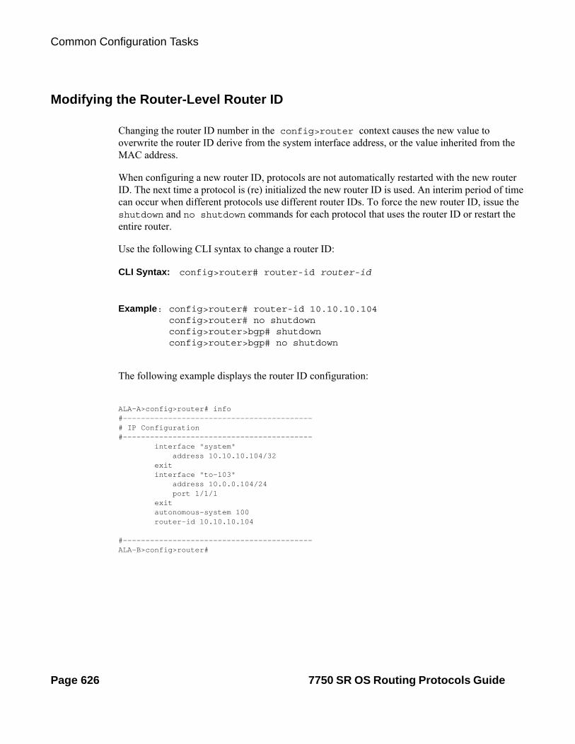
Common Configuration Tasks
Modifying the Router-Level Router ID
Changing the router ID number in the config>router context causes the new value to overwrite the router ID derive from the system interface address, or the value inherited from the MAC address.
When configuring a new router ID, protocols are not automatically restarted with the new router ID. The next time a protocol is (re) initialized the new router ID is used. An interim period of time can occur when different protocols use different router IDs. To force the new router ID, issue the shutdown and no shutdown commands for each protocol that uses the router ID or restart the entire router.
Use the following CLI syntax to change a router ID:
CLI Syntax: config>router# router-id router-id
Example: config>router# router-id 10.10.10.104config>router# no shutdownconfig>router>bgp# shutdownconfig>router>bgp# no shutdown
The following example displays the router ID configuration:
ALA-A>config>router# info#------------------------------------------# IP Configuration#------------------------------------------ interface "system" address 10.10.10.104/32 exit interface "to-103" address 10.0.0.104/24 port 1/1/1 exit autonomous-system 100 router-id 10.10.10.104
#------------------------------------------ALA-B>config>router#
Page 626 7750 SR OS Routing Protocols Guide

BGP
Deleting a Neighbor
In order to delete a neighbor, you must shut down the neighbor before issuing the no neighbor ip-addr command.
Use the following CLI syntax to delete a neighbor:
CLI Syntax: config>router# bgpgroup name
no neighbor ip-addressshutdown
no peer-as asn shutdown
Example: config>router# bgpconfig>router>bgp# group headquarters1config>router>bgp>group# neighbor 10.0.0.103config>router>bgp>group>neighbor# shutdownconfig>router>bgp>group>neighbor# exitconfig>router>bgp>group# no neighbor 10.0.0.103
The following example displays the “headquarters1” configuration with the neighbor 10.0.0.103 removed.
ALA-B>config>router>bgp# info---------------------------------------------- group "headquarters1"
description “HQ execs” local-address 10.0.0.104 neighbor 10.0.0.5 passive peer-as 300 exit
exit----------------------------------------------ALA-B>config>router>bgp#
7750 SR OS Routing Protocols Guide Page 627

Common Configuration Tasks
Deleting Groups
In order to delete a group, the neighbor configurations must be shut down first. After each neighbor is shut down, you must shut down the group before issuing the no group name command.
Use the following CLI syntax to shut down a peer and neighbor and then delete a group:
CLI Syntax: config>router# bgpno group nameshutdown
no neighbor ip-addressshutdown
shutdown
Example: config>router# bgpconfig>router>bgp# group headquarters1config>router>bgp>group# neighbor 10.0.0.105config>router>bgp>group>neighbor# shutdownconfig>router>bgp>group>neighbor# exitconfig>router>bgp>group# neighbor 10.0.0.103config>router>bgp>group# shutdownconfig>router>bgp>group# exitconfig>router>bgp# no group headquarters1
If you try to delete the group without shutting down the peer-group, the following message appears:
ALA-B>config>router>bgp# no group headquarters1MINOR: CLI BGP Peer Group should be shutdown before deleted. BGP Peer Group not deleted.
Page 628 7750 SR OS Routing Protocols Guide

BGP
BGP Command Reference
Command Hierarchies
Configuration Commands
• Global BGP Commands on page 629
• Group BGP Commands on page 632
• Neighbor BGP Commands on page 634
• Show Commands on page 636
• Clear Commands on page 636
• Debug Commands on page 637
config — router [router-name]
— confederation confed-as-num members as-number [as-number... (up to 15 max)] — no confederation [confed-as-num members as-number [as-number... (up to 15 max)] ] — [no] mh-primary-interface interface-name
— [no] address {ip-address/mask | ip-address netmask}— [no] description description-string— [no] shutdown
— [no] mh-secondary-interface interface-name— [no] address {ip-address/mask | ip-address netmask}— [no] description description-string— [no] shutdown— [no] hold-time holdover-time
— [no] mh-secondary-interface— router-id id-address— no router-id
—Global BGP Commands — [no] bgp— [no] add-paths
— ipv4 send send-limit receive [none]— ipv4 send send-limit— no ipv4— ipv6 send send-limit receive [none]— ipv6 end send-limit — no ipv6— vpn-ipv4 [send send-limit receive [none]— vpn-ipv4 end send-limit — no vpn-ipv4— vpn-ipv6 send send-limit receive [none]— vpn-ipv6 end send-limit — no vpn-ipv6
— [no] advertise-external [ipv4] [ipv6]— [no] advertise-inactive— [no] aggregator-id-zero
7750 SR OS Routing Protocols Guide Page 629

BGP Command Reference
— authentication-key [authentication-key | hash-key] [hash | hash2]— no authentication-key— auth-keychain name— backup-path [ipv4] [ipv6] [vpn-ipv4] [vpn-ipv6]— best-path-selection
— always-compare-med {zero | infinity}— always-compare-med strict-as {zero | infinity}— no always-compare-med— as-path-ignore [ipv4] [vpn-ipv4] [ipv6] [vpn-ipv6] [mcast-ipv4] [mvpn-ipv4]
[l2-vpn]— no as-path-ignore— ignore-nh-metric— ignore-router-id
— [no] bfd-enable— cluster cluster-id— no cluster— connect-retry seconds— no connect-retry— [no] damping— description description-string— no description— [no] disable-4byte-asn— [no] disable-client-reflect— disable-communities [standard] [extended]— no disable-communities— [no] disable-fast-external-failover— [no] enable-inter-as-vpn— [no] enable-peer-tracking— export policy-name [policy-name…(up to 5 max)]— no export — family [ipv4] [vpn-ipv4] [ipv6] [vpn-ipv6] [mcast-ipv4] [l2-vpn] [mvpn-ipv4] [mdt-
safi] [ms-pw] [flow-ipv4] [route-target]— no family— [no] flowspec-validate— [no] graceful-restart
— stale-routes-time time— no stale-routes-time
— hold-time seconds [strict]— no hold-time— [no] ibgp-multipath— igp-shortcut [ldp | rsvp-te | mpls] [disallow-igp]— no igp-shortcut— import policy-name [policy-name …(up to 5 max)]— no import — keepalive seconds— no keepalive— local-as as-number [private]— no local-as— local-preference local-preference— no local-preference— loop-detect {drop-peer | discard-route | ignore-loop | off}— no loop-detect— med-out {number | igp-cost}— no med-out
Page 630 7750 SR OS Routing Protocols Guide

BGP
— min-as-origination seconds — no min-as-origination— min-route-advertisement seconds— no min-route-advertisement— [no] mp-bgp-keep— multihop ttl-value— no multihop— multipath max-paths— no multipath— [no] outbound-route-filtering
— [no] extended-community— [no] accept-orf— send-orf [comm-id...(up to 32 max)]— no send-orf comm-id
— [no] path-mtu-discovery— preference preference— no preference— [no] rapid-update {[l2-vpn] [mvpn-ipv4] [mdt-safi]}— [no] rapid-withdrawal— [no] remove-private— route-target-list comm-id [comm-id...(up to 15 max)]— no route-target-list [comm-id]— router-id ip-address— no router-id— [no] shutdown— transport-tunnel ldp | rsvp-te | mpls— [no] vpn-apply-export— [no] vpn-apply-import
7750 SR OS Routing Protocols Guide Page 631

BGP Command Reference
—Group BGP Commands config — router [router-name]
— [no] bgp— [no] group name
— [no] add-paths — ipv4 send send-limit receive [none]— ipv4 send send-limit— no ipv4— ipv6 send send-limit receive [none]— ipv6 end send-limit — no ipv6— vpn-ipv4 [send send-limit receive [none]— vpn-ipv4 end send-limit — no vpn-ipv4— vpn-ipv6 send send-limit receive [none]— vpn-ipv6 end send-limit — no vpn-ipv6
— [no] advertise-inactive— [no] aggregator-id-zero— authentication-key [authentication-key | hash-key] [hash | hash2]— no authentication-key — auth-keychain name— [no] bfd-enable— cluster cluster-id— no cluster— connect-retry seconds— no connect-retry— [no] damping— [no] default-route-target— description description-string— no description— [no] disable-4byte-asn— [no] disable-capability-negotiation— [no] disable-client-reflect— disable-communities [standard] [extended]— no disable-communities— [no] disable-fast-external-failover— [no] enable-peer-tracking— export policy-name [policy-name…(up to 5 max)]— no export — family [ipv4] [vpn-ipv4] [ipv6] [mcast-ipv4] [l2-vpn] [mvpn-ipv4] [flow-
ipv4] [mdt-safi] [route target]— no family— [no] flowspec-validate— [no] graceful-restart
— stale-routes-time time— no stale-routes-time
— hold-time seconds [strict]— no hold-time— import policy-name [policy-name …(up to 5 max)]— no import — keepalive seconds— no keepalive
Page 632 7750 SR OS Routing Protocols Guide

BGP
— local-address ip-address— no local-address— local-as as-number [private]— no local-as— local-preference local preference— no local-preference— loop-detect {drop-peer | discard-route | ignore-loop | off}— no loop-detect— med-out {number | igp-cost}— no med-out— min-as-origination seconds — no min-as-origination— min-route-advertisement seconds— no min-route-advertisement— multihop ttl-value— no multihop— [no] next-hop-self {[ipv4] [vpn-ipv4] [ipv6] [mcast-ipv4] [l2-vpn]} [multi-
homing primary-anycast secondary-anycast]— [no] outbound-route-filtering
— [no] extended-community— [no] accept-orf— send-orf [comm-id...(up to 32 max)]— no send-orf [comm-id]
— [no] passive— [no] path-mtu-discovery— peer-as as-number— no peer-as— preference preference— no preference— prefix-limit limit [log-only] [threshold percent]— no prefix-limit — [no] remove-private— [no] shutdown— ttl-security min-ttl-value— no ttl-security— type {internal | external}— no type— [no] updated-error-handling— [no] vpn-apply-export— [no] vpn-apply-import
7750 SR OS Routing Protocols Guide Page 633

BGP Command Reference
—Neighbor BGP Commands config — router [router-name]
— [no] bgp— [no] group name
— [no] neighbor ip-address — [no] add-paths
— ipv4 send send-limit receive [none]— ipv4 send send-limit— no ipv4— ipv6 send send-limit receive [none]— ipv6 end send-limit — no ipv6— vpn-ipv4 [send send-limit receive [none]— vpn-ipv4 end send-limit — no vpn-ipv4— vpn-ipv6 send send-limit receive [none]— vpn-ipv6 end send-limit — no vpn-ipv6
— [no] advertise-inactive— advertise-label [ipv4 [include-ldp-prefix]] [ipv6]— [no] advertise-label— [no] aggregator-id-zero— auth-keychain name— authentication-key [authentication-key | hash-key] [hash | hash2]— no authentication-key — [no] bfd-enable— cluster cluster-id— no cluster— connect-retry seconds— no connect-retry— [no] damping— [no] default-route-target— description description-string— no description— [no] disable-4byte-asn— [no] disable-capability-negotiation— [no] disable-client-reflect— disable-communities [standard] [extended]— no disable-communities— [no] disable-fast-external-failover— [no] enable-peer-tracking— export policy-name [policy-name…(up to 5 max)]— no export — family [ipv4] [vpn-ipv4] [ipv6] [mcast-ipv4] [l2-vpn] [mvpn-ipv4]
[flow-ipv4] [mdt-safi] [route-target]— no family— [no] flowspec-validate— [no] graceful-restart
— stale-routes-time time— no stale-routes-time
— hold-time seconds [strict]— no hold-time— import policy-name [policy-name …(up to 5 max)]
Page 634 7750 SR OS Routing Protocols Guide

BGP
— no import — keepalive seconds— no keepalive— local-address ip-address— no local-address— local-as as-number [private]— no local-as— local-preference local-preference— no local-preference— loop-detect {drop-peer | discard-route | ignore-loop | off}— no loop-detect— med-out {number | igp-cost}— no med-out— min-as-origination seconds — no min-as-origination— min-route-advertisement seconds— no min-route-advertisement— multihop ttl-value— no multihop— [no] next-hop-self— [no] outbound-route-filtering
— [no] extended-community— [no] accept-orf
— send-orf [comm-id...(up to 32 max)]— no send-orf [comm-id]
— [no] passive— [no] path-mtu-discovery— peer-as as-number— no peer-as— preference preference— no preference— prefix-limit limit [log-only] [threshold percent]— no prefix-limit — [no] remove-private {limited}— [no] shutdown— ttl-security min-ttl-value— no ttl-security— type {internal | external}— no type— [no] updated-error-handling— [no] vpn-apply-export— [no] vpn-apply-import
Other BGP-Related Commands
config — router [router-name]
— autonomous-system as-number— no autonomous-system— router-id ip-address— no router-id
7750 SR OS Routing Protocols Guide Page 635

BGP Command Reference
Show Commands
show— router [router-instance]
— bgp— auth-keychain keychain-name— damping [damp-type] [detail]— damping [ip-prefix | prefix-length] [detail]— group [name] [detail]— neighbor [ip-address [detail]]— neighbor [as-number [detail]]— neighbor ip-address [family [type mvpn-type]] filter1 [brief]— neighbor ip-address [family] filter2 — neighbor as-number [family] filter2 — neighbor ip-address orf [filter3]— neighbor ip-address graceful-restart— next-hop [family] [ip-address] [detail]— paths— route-target— routes [family] [brief]— routes [family] prefix [detail | longer | hunt [brief]]— routes family [prefix] [detail | longer | hunt [brief]]— routes [family [type mvpn-type]] community comm-id— routes [family [type mvpn-type]] aspath-regex reg-ex— routes mvpn-ipv4 type mvpn-type {rd rd | originator-ip ip-address | source-ip ip-
address | group-ip ip-address | source-as as-number} [hunt| detail]— routes [family [l2vpn-type]] [brief]— routes [family [l2vpn-type]] community comm-id— routes [family [l2vpn-type]] aspath-regex reg-ex— routes l2-vpn l2vpn-type {[rd rd] | [siteid site-id] | [veid veid] [offset vpls-base-offset ]}— routes mdt-safi [rd rd] [grp-address mcast-grp-address] [brief]— routes ms-pw [rd rd] [aii-type2 aii-type2] [brief]— routes flow-ipv4— summary [all]— summary [family family] [neighbor ip-address]
— mvpn
Clear Commands
clear— router
— bgp— damping [{prefix/ip-prefix-length] [neighbor ip-address]} | {group name}]— flap-statistics [{prefix/mask [neighbor ip-address] | [group group-name] | [regex reg-exp
| policy policy-name}]— neighbor {ip-address | as as-number | external | all} [soft | soft-inbound]— neighbor {ip-address | as as-number | external | all} statistics— neighbor ip-address end-of-rib — protocol
Page 636 7750 SR OS Routing Protocols Guide

BGP
Debug Commands
debug— router
— bgp— events [neighbor ip-address | group name]— no events— graceful-restart [neighbor ip-address | group name]— no graceful-restart— keepalive [neighbor ip-address | group name]— no keepalive— notification [neighbor ip-address | group name]— no notification— open [neighbor ip-address | group name]— no open— [no] outbound-route-filtering— packets [neighbor ip-address | group name]— no packets— route-refresh [neighbor ip-address | group name]— no route-refresh— rtm [neighbor ip-address | group name]— no rtm— socket [neighbor ip-address | group name]— no socket— timers [neighbor ip-address | group name]\— no timers— update [neighbor ip-address | group name]— no update
7750 SR OS Routing Protocols Guide Page 637

BGP Command Reference
Page 638 7750 SR OS Routing Protocols Guide

BGP
Configuration Commands
bgp
Syntax [no] bgp
Context config>router
Description This command creates the BGP protocol instance and BGP configuration context. BGP is administratively enabled upon creation.
The no form of the command deletes the BGP protocol instance and removes all configuration parameters for the BGP instance. BGP must be shutdown before deleting the BGP instance. An error occurs if BGP is not shutdown first.
add-paths
Syntax [no] add-paths
Context config>router>bgpconfig>router>bgp>groupconfig>router>bgp>group>neighbor
Description This command allows adds the add-paths node to be the configured for one or more families configuration of the BGP instance, a group or a neighbor. The BGP add-paths capability allows the router to send and/or receive multiple paths per prefix to/from a peer.The add-paths command without additional parameters is equivalent to removing Add-Paths support for all address families, which causes sessions that previously negotiated the add-paths capability for one or more address families to go down and come back up without the add-paths capability.
The no form of the command (no add-paths) removes add-paths from the configuration of BGP, the group or the neighbor, causing sessions established using add-paths to go down and come back up without the add-paths capability.
Default no add-paths
7750 SR OS Routing Protocols Guide Page 639

Configuration Commands
ipv4
Syntax ipv4 send send-limit receive [none]ipv4 send send-limitno ipv4
Context config>router>bgp>add-pathsconfig>router>bgp>group>add-pathsconfig>router>bgp>group>neighbor>add-paths
Description This command is used to configure the add-paths capability for IPv4 routes (including labeled IPv4 routes). By default, add-paths is not enabled for IPv4 routes.
The maximum number of paths per IPv4 prefix to send is the configured send limit, which is a mandatory parameter. The capability to receive multiple paths per prefix from a peer is configurable using the receive keyword, which is optional. If the receive keyword is not included in the command the receive capability is enabled by default. Entering the command without optional parameters negotiates the ability to both send and receive multiple paths per IPv4 prefix with each peer and configures the router to send the two best paths per prefix to each peer using the default Add-N, N=2 path selection algorithm.
The no form of the command disables add-paths support for IPv4 routes, causing sessions established using add-paths for IPv4 to go down and come back up without the add-paths capability.
Default no ipv4
Parameters send send-limit — The maximum number of paths per IPv4 prefix that are allowed to be advertised to add-paths peers (the actual number of advertised routes may be less depending on the next-hop diversity requirement, other configuration options, route policies and/or route advertisement rules).
Values 1 — 16, none
receive — The router negotiates the add-paths receive capability for VPN-IPv4 routes with its peers
none — The router does not negotiate the Add-Paths receive capability for VPN-IPv64 routes with its peers.
ipv6
Syntax ipv6 send send-limit receive [none]ipv6 send send-limitno ipv6
Context config>router>bgp>add-pathsconfig>router>bgp>group>add-pathsconfig>router>bgp>group>neighbor>add-paths
Description This command is used to configure the add-paths capability for IPv6 routes (including 6PE routes). By default, add-paths is not enabled for IPv6 routes.
Page 640 7750 SR OS Routing Protocols Guide

BGP
The maximum number of paths per IPv6 prefix to send is the configured send-limit, which is a mandatory parameter. The capability to receive multiple paths per prefix from a peer is configurable using the receive keyword, which is optional. If the receive keyword is not included in the command the receive capability is enabled by default.
The no form of the command disables add-paths support for IPv6 routes, causing sessions established using add-paths for IPv6 to go down and come back up without the add-paths capability.
Default no ipv6
Parameters send send-limit — The maximum number of paths per IPv6 prefix that are allowed to be advertised to add-paths peers (the actual number of advertised routes may be less depending on the next-hop diversity requirement, other configuration options, route policies and/or route advertisement rules).
Values 1 — 16, none
receive — The router negotiates the add-paths receive capability for VPN-IPv6 routes with its peers
none — The router does not negotiate the Add-Paths receive capability for VPN-IPv6 routes with its peers.
vpn-ipv4
Syntax vpn-ipv4 send send-limit receive [none]vpn-ipv4 send send-limitno vpn-ipv4
Context config>router>bgp>add-pathsconfig>router>bgp>group>add-pathsconfig>router>bgp>group>neighbor>add-paths
Description This command is used to configure the add-paths capability for VPN-IPv4 routes. By default, add-paths is not enabled for VPN-IPv4 routes.
The maximum number of paths per VPN-IPv4 NLRI to send is the configured send-limit, which is a mandatory parameter. The capability to receive multiple paths per prefix from a peer is configurable using the receive keyword, which is optional. If the receive keyword is not included in the command the receive capability is enabled by default.
The no form of the command disables add-paths support for VPN-IPv4 routes, causing sessions established using add-paths for VPN-IPv4 to go down and come back up without the add-paths capability.
Default no vpn-ipv4
Parameters send-limit — The maximum number of paths per VPN-IPv4 NLRI that are allowed to be advertised to add-paths peers (the actual number of advertised routes may be less depending on the next-hop diversity requirement, other configuration options, route policies and/or route advertisement rules).
Values 1 — 16, none
receive — The router negotiates the add-paths receive capability for VPN-IPv4 routes with its peers
none — The router does not negotiate the Add-Paths receive capability for VPN-IPv64 routes with its peers.
7750 SR OS Routing Protocols Guide Page 641

Configuration Commands
vpn-ipv6
Syntax vpn-ipv6 send send-limit receive [none]vpn-ipv6 send send-limitno vpn-ipv6
Context config>router>bgp>add-pathsconfig>router>bgp>group>add-pathsconfig>router>bgp>group>neighbor>add-paths
Description This command is used to configure the add-paths capability for VPN-IPv6 routes. By default, add-paths is not enabled for VPN-IPv6 routes.
The maximum number of paths per VPN-IPv6 NLRI to send is the configured send-limit, which is a mandatory parameter. The capability to receive multiple paths per prefix from a peer is configurable using the receive keyword, which is optional. If the receive keyword is not included in the command the receive capability is enabled by default.
The no form of the command disables add-paths support for VPN-IPv6 routes, causing sessions established using add-paths for VPN-IPv6 to go down and come back up without the add-paths capability.
Default no vpn-ipv6
Parameters send-limit — The maximum number of paths per VPN-IPv6 NLRI that are allowed to be advertised to add-paths peers (the actual number of advertised routes may be less depending on the next-hop diversity requirement, other configuration options, route policies and/or route advertisement rules).
Values 1 — 16, none
receive — The router negotiates the add-paths receive capability for VPN-IPv6 routes with its peers
none — The router does not negotiate the add-paths receive capability for VPN-IPv6 routes with its peers.
advertise-external
Syntax [no] advertise-external [ipv4] [ipv6]
Context config>router>bgp
Description This command allows BGP to advertise its best external route to a destination even when its best overall route is an internal route. Entering the command (or its no form) with no address family parameters is equivalent to specifying all supported address families.
The no form of the command disables Advertise Best External for the BGP family.
Default no advertise-external
Parameters ipv4 — Enable/disable best-external advertisement for all IPv4 (unicast and labeled-unicast) routes.
ipv6 — Enable/disable best-external advertisement for all IPv6 (unicast and labeled-unicast) routes.
Page 642 7750 SR OS Routing Protocols Guide

BGP
advertise-inactive
Syntax [no] advertise-inactive
Context config>router>bgpconfig>router>bgp>groupconfig>router>bgp>group>neighbor
Description This command enables the advertising of inactive BGP routes to other BGP peers. By default, BGP only advertises BGP routes to other BGP peers if a given BGP route is chosen by the route table manager as the most preferred route within the system and is active in the forwarding plane. This command allows system administrators to advertise a BGP route even though it is not the most preferred route within the system for a given destination.
The no form of the command disables the advertising of inactive BGP routers to other BGP peers.
Default no advertise-inactive
advertise-label
Syntax advertise-label [ipv4 [include-ldp-prefix]] [ipv6]no advertise-label
Context config>router>bgp>group>neighbor
Description This command configures the IPv4 transport peers to exchange IPv6 prefixes using 6PE, LDP FEC prefixes as RFC3107 labeled IPv4, as well as RFC 3107-labeled IPv4 routes.
If ipv4 is enabled all IPv4 routes advertised to the remote BGP peer will be sent with an RFC 3107- formatted label for the destination route. If include-ldp-fec-prefix option is also enabled, all activated /32 LDP FEC prefixes will be sent the to remote BGP peer with an RFC 3107 formatted label.
If ipv6 is enabled all IPv6 routes advertised to the remote BGP peer will be sent using the 6PE encapsulation.
The no form of the command disables any or all configured options.
The command must include one or more of the options above.
Default no advertise-label
Parameters ipv4 — Specifies the advertisement label address family for core IPv4 routes. This keyword can be specified only for an IPv4 peer.
include-ldp-prefix — Specifies the inclusion of LDP FEC prefixes in the advertisement of core IPv4 routes as EFC 3107 labeled routes to the peer.
ipv6 — Specifies the advertisement label address family to support the 6PE feature. This keyword can be specified only for an IPv6 peer.
7750 SR OS Routing Protocols Guide Page 643

Configuration Commands
aggregator-id-zero
Syntax [no] aggregator-id-zero
Context config>router>bgpconfig>router>bgp>groupconfig>router>bgp>group>neighbor
Description This command is used to set the router ID in the BGP aggregator path attribute to zero when BGP aggregates routes. This prevents different routers within an AS from creating aggregate routes that contain different AS paths.
When BGP is aggregating routes, it adds the aggregator path attribute to the BGP update messages. By default, BGP adds the AS number and router ID to the aggregator path attribute.
When this command is enabled, BGP adds the router ID to the aggregator path attribute. This command is used at the group level to revert to the value defined under the global level, while this command is used at the neighbor level to revert to the value defined under the group level.
The no form of the command used at the global level reverts to default where BGP adds the AS number and router ID to the aggregator path attribute.The no form of the command used at the group level reverts to the value defined at the global level.The no form of the command used at the neighbor level reverts to the value defined at the group level.
Default no aggregator-id-zero — BGP adds the AS number and router ID to the aggregator path attribute.
always-compare-med
Syntax always-compare-med {zero | infinity}no always-compare-med strict-as {zero | infinity}no always-compare-med
Context config>router>bgp>best-path-selectionconfig>service>vprn>bgp>best-path-selection
Description This command configures the comparison of BGP routes based on the MED attribute. The default behavior of SR-OS (equivalent to the no form of the command) is to only compare two routes on the basis of MED if they have the same neighbor AS (the first non-confed AS in the received AS_PATH attribute), and they both have a MED attribute. The always-compare-med command without the strict-as keyword allows BGP paths to be compared even if they have different neighbor AS (in this case, if neither zero or infinity is part of the command, the comparison requires both paths to have a MED attribute, otherwise, zero or infinity specifies the MED value that should be inferred for paths without the attribute. When the strict-as keyword is present, MED is only compared between paths from the same neighbor AS, and in this case, zero or infinity is mandatory and tells BGP how to interpret paths without a MED attribute.
The no form of the command removes the parameter from the configuration.
Default no always-compare-med — Only compare MEDs of routes that have the same peer AS.
Parameters zero — Specifies that for routes learned without a MED attribute that a zero (0) value is used in the MED comparison. The routes with the lowest metric are the most preferred.
Page 644 7750 SR OS Routing Protocols Guide

BGP
infinity — Specifies for routes learned without a MED attribute that a value of infinity (2^32-1) is used in the MED comparison. This in effect makes these routes the least desirable.
strict-as — Specifies BGP paths to be compared even with different neighbor AS.
as-path-ignore
Syntax as-path-ignore [ipv4] [vpn-ipv4] [ipv6] [vpn-ipv6] [mcast-ipv4] [mvpn-ipv4] [l2-vpn]no as-path-ignore
Context config>router>bgp>best-path-selectionconfig>service>vprn>bgp>best-path-selection
Description This command determines whether the AS path is used to determine the best BGP route.
If this option is present, the AS paths of incoming routes are not used in the route selection process.
The no form of the command removes the parameter from the configuration.
Default no as-path-ignore
Parameters ipv4 — Specifies that the AS-path length will be ignored for all IPv4 routes.
vpn-ipv4 — Specifies that the lengthAS-path will be ignored for all IPv4 VPRN routes.
ipv6 — Specifies that the AS-path length will be ignored for all IPv6 routes.
vpn-ipv6 — Specifies that the AS-path length will be ignored for all IPv6 VPRN routes.
mcast-ipv4 — Specifies that the AS-path length will be ignored for all IPv4 multicast routes.
mvpn-ipv4 — Specifies that the AS-path length will be ignored for all mVPN IPv4 multicast routes.
l2-vpn — The AS-path length will be ignored for all L2-VPN NLRIs.
auth-keychain
Syntax auth-keychain name
Context config>router>bgpconfig>router>bgp>groupconfig>router>bgp>group>neighbor
Description This command configures a TCP authentication keychain to use for the session. The keychain allows the rollover of authentication keys during the lifetime of a session.
Default no auth-keychain
Parameters name — Specifies the name of the keychain, up to 32 characters, to use for the specified TCP session or ses-sions.
7750 SR OS Routing Protocols Guide Page 645

Configuration Commands
authentication-key
Syntax authentication-key [authentication-key | hash-key] [hash | hash2]no authentication-key
Context config>router>bgpconfig>router>bgp>groupconfig>router>bgp>group>neighbor
Description This command configures the BGP authentication key.
Authentication is performed between neighboring routers before setting up the BGP session by verifying the password. Authentication is performed using the MD-5 message based digest.
The authentication key can be any combination of ASCII characters up to 255 characters long.
The no form of the command reverts to the default value.
Default MD5 Authentication is disabled by default.
Parameters authentication-key — The authentication key. The key can be any combination of ASCII characters up to 255 characters in length (unencrypted). If spaces are used in the string, enclose the entire string in quo-tation marks (“ ”).
hash-key — The hash key. The key can be any combination of ASCII characters up to 342 characters in length (encrypted). If spaces are used in the string, enclose the entire string in quotation marks (“ ”).
This is useful when a user must configure the parameter, but, for security purposes, the actual unen-crypted key value is not provided.
hash — Specifies the key is entered in an encrypted form. If the hash parameter is not used, the key is assumed to be in a non-encrypted, clear text form. For security, all keys are stored in encrypted form in the configuration file with the hash parameter specified.
hash2 — Specifies the key is entered in a more complex encrypted form. If the hash2 parameter is not used, the less encrypted hash form is assumed.
backup-path
Syntax backup-path [ipv4] [ipv6] [vpn-ipv4] [vpn-ipv6]no backup-path [ipv4] [ipv6]
Context config>router>bgpconfig>service>vprn>bgp
Description This command enables the computation and use of a backup path for IPv4 and/or IPv6 BGP routes belonging to the base router or a particular VPRN. Multiple paths must be received for a route in order to take advantage of this feature. When a route has a backup path and the last of its primary paths (the equal-cost best paths selected by the multipath algorithm) becomes unreachable, traffic matching the route is quickly diverted to the backup path. When many routes share the same set of primary paths and the same backup path, the time to failover traffic to the backup path is independent of the number of routes.
By default, IPv4 and IPv6 routes do not have a backup path installed in the FIB.
Page 646 7750 SR OS Routing Protocols Guide
BGP
Default no backup-path
Parameters ipv4 — Enables the use of a backup path for IPv4 BGP routes (excluding labeled IPv4 routes and VPN-IPv4 routes); disable the use of a backup path for IPv4 BGP routes when present in the no form of the command (as in no backup-path ipv4)
ipv6 — Enables the use of a backup path for IPv6 BGP routes (excluding labeled IPv6 routes and VPN-IPv6 routes); disable the use of a backup path for IPv6 BGP routes when present in the no form of the command (as in no backup-path ipv6)
vpn-ipv4 — Enables the use of a backup path for vpn-ipv4 BGP routes; disables the use of a backup path for vpn-ipv4 BGP routes when present in the no form of the command (as in no backup-path vpn-ipv4)
vpn-ipv6 — Enables the use of a backup path for vpn-ipv6 BGP routes; disables the use of a backup path for vpn-ipv6 BGP routes when present in the no form of the command (as in no backup-path vpn-ipv6)
best-path-selection
Syntax best-path-selection
Context config>router>bgp
Description This command enables path selection configuration.
bfd-enable
Syntax [no] bfd-enable
Context config>router>bgpconfig>router>bgp>groupconfig>router>bgp>group>neighbor
Description This command enables the use of bi-directional forwarding (BFD) to control the state of the associated protocol interface. By enabling BFD on a given protocol interface, the state of the protocol interface is tied to the state of the BFD session between the local node and the remote node. The parameters used for the BFD are set via the BFD command under the IP interface.
The no form of this command removes BFD from the associated IGP/BGP protocol adjacency.
Default no bfd-enable
7750 SR OS Routing Protocols Guide Page 647
Configuration Commands
cluster
Syntax cluster cluster-idno cluster
Context config>router>bgpconfig>router>bgp>groupconfig>router>bgp>group>neighbor
Description This command configures the cluster ID for a route reflector server.
Route reflectors are used to reduce the number of IBGP sessions required within an AS. Normally, all BGP speakers within an AS must have a BGP peering with every other BGP speaker in an AS. A route reflector and its clients form a cluster. Peers that are not part of the cluster are considered to be non-clients.
When a route reflector receives a route, first it must select the best path from all the paths received. If the route was received from a non-client peer, then the route reflector sends the route to all clients in the cluster. If the route came from a client peer, the route reflector sends the route to all non-client peers and to all client peers except the originator.
For redundancy, a cluster can have multiple route reflectors.
Confederations can also be used to remove the full IBGP mesh requirement within an AS.
The no form of the command deletes the cluster ID and effectively disables the Route Reflection for the given group.
Default no cluster — No cluster ID is defined.
Parameters cluster-id — The route reflector cluster ID is expressed in dot decimal notation.
Values Any 32 bit number in dot decimal notation. (0.0.0.1 — 255.255.255.255)
confederation
Syntax confederation confed-as-num members member-as-num no confederation confed-as-num [members member-as-num]
Context config>router
Description This command creates confederation autonomous systems within an AS.
This technique is used to reduce the number of IBGP sessions required within an AS. Route reflection is the other technique that is commonly deployed to reduce the number of IBGP sessions.
The no form of the command deletes the specified member AS from the confederation.
When members are not specified in the no statement, the entire list is removed and confederations is disabled.
When the last member of the list is removed, confederations is disabled.
Default no confederation — No confederations are defined.
Page 648 7750 SR OS Routing Protocols Guide
BGP
Parameters confed-as-num — The confederation AS number expressed as a decimal integer.
Values 1 — 65535
members member-as-num — The AS number(s) of members that are part of the confederation expressed as a decimal integer. Configure up to 15 members per confed-as-num.
connect-retry
Syntax connect-retry secondsno connect-retry
Context config>router>bgpconfig>router>bgp>groupconfig>router>bgp>group>neighbor
Description This command configures the BGP connect retry timer value in seconds.
When this timer expires, BGP tries to reconnect to the configured peer. This configuration parameter can be set at three levels: global level (applies to all peers), peer-group level (applies to all peers in group) or neighbor level (only applies to specified peer). The most specific value is used.
The no form of the command used at the global level reverts to the default value.The no form of the command used at the group level reverts to the value defined at the global level. The no form of the command used at the neighbor level reverts to the value defined at the group level.
Default 120 seconds
Parameters seconds — The BGP Connect Retry timer value in seconds expressed as a decimal integer.
Values 1 — 65535
damping
Syntax [no] damping
Context config>router>bgpconfig>router>bgp>groupconfig>router>bgp>group>neighbor
Description This command enables BGP route damping for learned routes which are defined within the route policy. Use damping to reduce the number of update messages sent between BGP peers and reduce the load on peers without affecting the route convergence time for stable routes. Damping parameters are set via route policy definition.
The no form of the command used at the global level reverts route damping.The no form of the command used at the group level reverts to the value defined at the global level.The no form of the command used at the neighbor level reverts to the value defined at the group level.
When damping is enabled and the route policy does not specify a damping profile, the default damping profile is used. This profile is always present and consists of the following parameters:
7750 SR OS Routing Protocols Guide Page 649

Configuration Commands
Half-life: 15 minutes Max-suppress: 60 minutes Suppress-threshold: 3000 Reuse-threshold: 750
Default no damping — Learned route damping is disabled.
default-route-target
Syntax default-route-targetno default-route-target
Context config>router>bgp>groupconfig>router>bgp>group>neighbor
Description This command originates the default RTC route (zero prefix length) towards the selected peers.
Default No default RTC routes are advertised by the router.
description
Syntax description description-stringno description
Context config>router>bgpconfig>router>bgp>groupconfig>router>bgp>group>neighbor
Description This command creates a text description stored in the configuration file for a configuration context.
The no form of the command removes the description string from the context.
Default No description is associated with the configuration context.
Parameters string — The description character string. Allowed values are any string up to 80 characters long composed of printable, 7-bit ASCII characters. If the string contains special characters (#, $, spaces, etc.), the entire string must be enclosed within double quotes.
disable-4byte-asn
Syntax [no] disable-4byte-asn
Context config>router>bgpconfig>router>bgp>groupconfig>router>bgp>group>neighbor
Description This command disables the use of 4-byte ASNs. It can be configured at all 3 level of the hierarchy so it can be specified down to the per peer basis.
Page 650 7750 SR OS Routing Protocols Guide

BGP
If this command is enabled 4-btye ASN support should not be negotiated with the associated remote peer(s).
The no form of the command resets the behavior to the default which is to enable the use of 4-byte ASN.
disable-capability-negotiation
Syntax [no] disable-capability-negotiation
Context config>router>bgp>groupconfig>router>bgp>group>neighbor
Description This command disables the exchange of capabilities. When command is enabled and after the peering is flapped, any new capabilities are not negotiated and will strictly support IPv4 routing exchanges with that peer.
The no form of the command removes this command from the configuration and restores the normal behavior.
Default no disable-capability-negotiation
disable-client-reflect
Syntax [no] disable-client-reflect
Context config>router>bgpconfig>router>bgp>groupconfig>router>bgp>group>neighbor
Description This command disables the reflection of routes by the route reflector to the clients in a specific group or neighbor.
This only disables the reflection of routes from other client peers. Routes learned from non-client peers are still reflected to all clients.
The no form re-enables client reflection of routes.
Default no disable-client-reflect — Client routes are reflected to all client peers.
disable-communities
Syntax disable-communities [standard] [extended]no disable-communities
Context config>router>bgpconfig>router>bgp>groupconfig>router>bgp>group>neighbor
Description This command configures BGP to disable sending communities.
7750 SR OS Routing Protocols Guide Page 651

Configuration Commands
Parameters standard — Specifies standard communities that existed before VPRNs or 2547.
extended — Specifies BGP communities used were expanded after the concept of 2547 was introduced, to include handling the VRF target.
disable-fast-external-failover
Syntax [no] disable-fast-external-failover
Context config>router>bgpconfig>router>bgp>groupconfig>router>bgp>group>neighbor
Description This command configures BGP fast external failover.
enable-inter-as-vpn
Syntax [no] enable-inter-as-vpn
Context config>router>bgp
Description This command specifies whether VPNs can exchange routes across autonomous system boundaries, providing model B connectivity
The no form of the command disallows ASBRs to advertise VPRN routes to their peers in other autonomous systems.
Default no enable-inter-as-vpn
enable-peer-tracking
Syntax [no] enable-peer-tracking
Context config>router>bgpconfig>router>bgp>groupconfig>router>bgp>group>neighbor
Description This command enables BGP peer tracking. BGP peer tracking allows a BGP peer to be dropped immediately if the route used to resolve the BGP peer address is removed from the IP routing table and there is no alternative available. The BGP peer will not wait for the holdtimer to expire; therefore, the BGP reconvergance process is accelerated.
The no form of the command disables peer tracking.
Default no enable-peer-tracking
Page 652 7750 SR OS Routing Protocols Guide

BGP
export
Syntax export policy-name [policy-name…]no export [policy-name]
Context config>router>bgpconfig>router>bgp>groupconfig>router>bgp>group>neighbor
Description This command specifies the export route policy used to determine which routes are advertised to peers.
This configuration parameter can be set at three levels: global level (applies to all peers), group level (applies to all peers in peer-group) or neighbor level (only applies to specified peer). The most specific level is used.
When multiple policy names are specified, the policies are evaluated in the order they are specified. A maximum of five (5) policy names can be configured. The first policy that matches is applied.
When multiple export commands are issued, the last command entered overrides the previous command.
When no export policies are specified, BGP routes are advertised and non-BGP routes are not advertised by default.
The no form of the command removes the policy association with the BGP instance. To remove association of all policies, use the no export command without arguments.
Default no export — No export policy is specified. BGP routes are advertised and non-BGP routes are not advertised.
Parameters policy-name — The route policy name. Allowed values are any string up to 32 characters long composed of printable, 7-bit ASCII characters. If the string contains special characters (#, $, spaces, etc.), the entire string must be enclosed within double quotes. Route policies are configured in the config>router>pol-icy-options context.
family
Syntax family [ipv4] [vpn-ipv4] [ipv6] [mcast-ipv4] [l2-vpn] [mvpn-ipv4] [flow-ipv4] [mdt-safi] [ms-pw] [route-target]no family
Context config>router>bgpconfig>router>bgp>groupconfig>router>bgp>group>neighbor
Description This command specifies the address family or families to be supported over BGP peerings in the base router. This command is additive so issuing the family command adds the specified address family to the list.
The no form of the command removes the specified address family from the associated BGP peerings. If an address family is not specified, then reset the supported address family back to the default.
Default ipv4
Parameters ipv4 — Provisions support for IPv4 routing information.
7750 SR OS Routing Protocols Guide Page 653

Configuration Commands
vpn-ipv4 — Exchanges IPv4 VPN routing information.
ipv6 — Exchanges IPv6 routing information.
mcast-ipv4 — Exchanges multicast IPv4 routing information.
l2-vpn — Exchanges Layer 2 VPN information.
mvpn-ipv4 — Exchanges Multicast VPN related information.
flow-ipv4 — Exchanges IPv4 flowspec routes belonging to AFI 1 and SAFI 133.
mdt-safi — Exchanges Multicast VPN information using MDT-SAFI address family
ms-pw — Exchanges dynamic MS-PW related information.
route-target — Exchanges RT constraint routes for VPN route filtering.
flowspec-validate
Syntax flowspec-validateno flowspec-validate
Context config>router>bgpconfig>router>bgp>groupconfig>router>bgp>group>neighbor
Description This command enables/disables validation of received flowspec routes. A flow route with a destination prefix subcomponent received from a particular peer is considered valid if and only if that peer also advertised the best unicast route to the destination prefix and any of its more-specific components. Also, when a flow route is received from an EBGP peer the leftmost AS number in the AS_PATH attribute must equal the peer's AS number. If validation is enabled and a flowspec route is not valid it is not eligible for import into the RIB, it is not used for filtering, a log/trap is generated and it is not propagated to other flowspec peers.
The no form of the command disables the validation procedure.
Default no flowspec-validate
route-target-list
Syntax route-target-list comm-id [comm-id ..[up to 15 max]]no route-target-list [comm-id]
Context config>router>bgp
Description This command specifies the route target(s) to be accepted and advertised from/to route reflector clients. If the route-target-list is a non-null list, only routes with one or more of the given route targets are accepted or advertised to route reflector clients.
This command is only applicable if the router is a route-reflector server. This parameter has no affect on non-route-reflector clients.
Page 654 7750 SR OS Routing Protocols Guide

BGP
If the route-target-list is assigned at the global level, then the list applies to all route-reflector clients connected to the system.
The no form of the command with a specified route target community, removes the specified community from the route-target-list. The no form of the command entered without a route target community removes all communities from the list.
Default no route-target-list
Parameters comm-id — Specifies the route target community in the form <0..65535>:<0..65535>
updated-error-handling
Syntax [no] updated-error-handling
Context config>router>bgp>groupconfig>router>bgp>group>neighbor
Description This command controls whether SROS utilizes the new neighbor-complete bit when processing optional transitive path attributes and advertising them to the associated BGP neighbor.
This command also control if SROS utilizes the error handling mechanism for optional-transitive path attributes.
Default no updated-error-handling
vpn-apply-export
Syntax [no] vpn-apply-export
Context config>router>bgpconfig>router>bgp>groupconfig>router>bgp>group>neighbor
Description This command causes the base instance BGP export route policies to be applied to VPN-IPv4 routes.
The no form of the command disables the application of the base instance BGP route policies to VPN-IPv4 routes.
Default no vpn-apply-export
7750 SR OS Routing Protocols Guide Page 655

Configuration Commands
vpn-apply-import
Syntax [no] vpn-apply-import
Context config>router>bgpconfig>router>bgp>groupconfig>router>bgp>group>neighbor
Description This command causes the base instance BGP import route policies to be applied to VPN-IPv4 routes.
The no form of the command disables the application of the base instance BGP import route policies to VPN-IPv4 routes.
Default no vpn-apply-import
graceful-restart
Syntax [no] graceful-restart
Context config>router>bgpconfig>router>bgp>groupconfig>router>bgp>group>neighbor
Description This command enables graceful-restart for BGP. When the control plane of a GR-capable router fails, the neighboring routers (GR helpers) temporarily preserve neighbor information, so packets continue to be forwarded through the failed GR router using the last known routes. The helper state remains until the peer completes its restart or exits if the GR timer value is exceeded.
The no form of the command disables graceful restart and removes all graceful restart configurations in the BGP instance.
Default no graceful-restart
stale-routes-time
Syntax stale-routes-time timeno stale-routes-time
Context config>router>bgp>graceful-restartconfig>router>bgp>group>graceful-restartconfig>router>bgp>group>neighbor>graceful-restart
Description This command configures the maximum amount of time in seconds that stale routes should be maintained after a graceful restart is initiated.
The no form of the command resets the stale routes time back to the default of 360 seconds.
Default no restart time
Page 656 7750 SR OS Routing Protocols Guide

BGP
Parameters time — Specify the amount of time that stale routes should be maintained after a graceful restart is initiated.
Values 1 — 3600 seconds
group
Syntax [no] group name
Context config>router>bgp
Description This command creates a context to configure a BGP peer group.
The no form of the command deletes the specified peer group and all configurations associated with the peer group. The group must be shutdown before it can be deleted.
Default No peer groups are defined.
Parameters name — The peer group name. Allowed values are any string up to 32 characters long composed of print-able, 7-bit ASCII characters. If the string contains special characters (#, $, spaces, etc.), the entire string must be enclosed within double quotes.
hold-time
Syntax hold-time seconds [min seconds2]no hold-time
Context config>router>bgpconfig>router>bgp>groupconfig>router>bgp>group>neighbor
Description This command configures the BGP hold time, expressed in seconds.
The BGP hold time specifies the maximum time BGP waits between successive messages (either keepalive or update) from its peer, before closing the connection. This configuration parameter can be set at three levels: global level (applies to all peers), group level (applies to all peers in group) or neighbor level (only applies to specified peer). The most specific value is used.
Even though the implementation allows setting the keepalive time separately, the configured keepalive timer is overridden by the hold-time value under the following circumstances:
1. If the specified hold-time is less than the configured keepalive time, then the operational keepalive time is set to a third of the hold-time; the configured keepalive time is not changed.
2. If the hold-time is set to zero, then the operational value of the keepalive time is set to zero; the con-figured keepalive time is not changed. This means that the connection with the peer is up permanently and no keepalive packets are sent to the peer.
The no form of the command used at the global level reverts to the default value.The no form of the command used at the group level reverts to the value defined at the global level.The no form of the command used at the neighbor level reverts to the value defined at the group level.
Default 90 seconds
7750 SR OS Routing Protocols Guide Page 657

Configuration Commands
Parameters seconds — The hold-time, in seconds, expressed as a decimal integer. A value of 0 indicates the connection to the peer is up permanently.
Values 0, 3 — 65535
seconds2 — The minimum hold-time that will be accepted for the session. If the peer proposes a hold-time lower than this value, the session attempt will be rejected.
ibgp-multipath
Syntax [no] ibgp-multipath
Context config>router>bgp
Description This command enables IBGP multipath load balancing when adding BGP routes to the route table if the route resolving the BGP nexthop offers multiple nexthops.
The no form of the command disables the IBGP multipath load balancing feature.
Default no ibgp-multipath
ignore-nh-metric
Syntax ignore-nh-metric no ignore-nh-metric
Context config>router>bgp>best-path-selectionconfig>service>vprnconfig>service>vprn>bgp>best-path-selection
Description This command instructs BGP to disregard the resolved distance to the BGP next-hop in its decision process for selecting the best route to a destination. When configured in the config>router>bgp>best-path-selection context, this command applies to the comparison of two BGP routes with the same NLRI learned from base router BGP peers. When configured in the config>service>vprn context, this command applies to the comparison of two BGP-VPN routes for the same IP prefix imported into the VPRN from the base router BGP instance. When configured in the config>service>vprn>bgp>best-path-selection context, this command applies to the comparison of two BGP routes for the same IP prefix learned from VPRN BGP peers.
The no form of the command (no ignore-nh-metric) restores the default behavior whereby BGP factors distance to the next-hop into its decision process.
Default no ignore-nh-metric
Page 658 7750 SR OS Routing Protocols Guide

BGP
ignore-router-id
Syntax ignore-router-idno ignore-router-id
Context config>router>bgp>best-path-selectionconfig>service>vprn>bgp>best-path-selection
Description When the ignore-router-id command is present and the current best path to a destination was learned from EBGP peer X with BGP identifier x and a new path is received from EBGP peer Y with BGP identifier y the best path remains unchanged if the new path is equivalent to the current best path up to the BGP identifier comparison – even if y is less than x. The no form of the command restores the default behavior of selecting the route with the lowest BGP identifier (y) as best.
Default no ignore-router-id
igp-shortcut
Syntax igp-shortcut [ldp | rsvp-te | mpls] [disallow-igp]no igp-shortcut
Context config>router>bgp
Description This command enables the use of LDP tunnels, RSVP tunnels, or both, to resolve paths to BGP next-hops.
The ldp option instructs BGP to search for an LDP LSP with a FEC prefix corresponding to the /32 address of the BGP next-hop. This deprecates the existing ldp-shortcut command under BGP. Support for the older command will be provided over a number of releases to allow old config files to execute.
The rsvp-te option instructs BGP to search for the best metric RSVP LSP to the /32 address of the BGP next-hop. This address can correspond to the system interface or to another loopback used by the BGP instance on the remote node as its router-id. The LSP metric is provided by MPLS in the tunnel table.
The mpls option instructs BGP to first attempt to resolve the BGP next-hop to an RSVP LSP. If no RSVP LSP exists or if the existing ones are down, BGP will automatically search for the LDP LSP with a FEC prefix corresponding to the same /32 prefix in the tunnel table and will resolve the BGP next-hop to it.
The disallow-igp option also deprecates the existing one under BGP. It continues to work transparently regardless of which type of LSP shortcut, RSVP or LDP, is being used by BGP at any given time. When this option is enabled and if an LSP shortcut of the configured type is not available, the IGP next-hop route will not be used for the BGP next-hop resolution.
Default no igp-shortcut
Parameters ldp — Enables the use of LDP LSPs for BGP next-hop resolution by BGP.
rsvp-te — Enables the use of RSVP LSPs for BGP next-hop resolution by BGP.
mpls — Enables the use of both RSVP and LDP LSPs for BGP next-hop resolution by BGP. RSVP LSPs are preferred.
disallow-igp — Prevents BGP next-hop resolution to a regular IGP next-hop if no LSP shortcut was found.
7750 SR OS Routing Protocols Guide Page 659

Configuration Commands
import
Syntax import policy-name [policy-name…]no import [policy-name]
Context config>router>bgpconfig>router>bgp>groupconfig>router>bgp>group>neighbor
Description This command specifies the import route policy to be used to determine which routes are accepted from peers. Route policies are configured in the config>router>policy-options context.
This configuration parameter can be set at three levels: global level (applies to all peers), group level (applies to all peers in peer-group) or neighbor level (only applies to specified peer). The most specific level is used.
When multiple policy names are specified, the policies are evaluated in the order they are specified. A maximum of five (5) policy names can be specified. The first policy that matches is applied.
When multiple import commands are issued, the last command entered will override the previous command.
When an import policy is not specified, BGP routes are accepted by default.
The no form of the command removes the policy association with the BGP instance. To remove association of all policies, use no import without arguments.
Default no import — No import policy specified (BGP routes are accepted).
Parameters policy-name — The route policy name. Allowed values are any string up to 32 characters long composed of printable, 7-bit ASCII characters. If the string contains special characters (#, $, spaces, etc.), the entire string must be enclosed within double quotes. Route policies are configured in the config>router>pol-icy-options context.
keepalive
Syntax keepalive secondsno keepalive
Context config>router>bgpconfig>router>bgp>groupconfig>router>bgp>group>neighbor
Description This command configures the BGP keepalive timer. A keepalive message is sent every time this timer expires.
The keepalive parameter can be set at three levels: global level (applies to all peers), group level (applies to all peers in peer-group) or neighbor level (only applies to specified peer). The most specific value is used.
The keepalive value is generally one-third of the hold-time interval. Even though the implementation allows the keepalive value and the hold-time interval to be independently set, under the following circumstances, the configured keepalive value is overridden by the hold-time value:
1. If the specified keepalive value is greater than the configured hold-time, then the specified value is ignored, and the keepalive is set to one third of the current hold-time value.
Page 660 7750 SR OS Routing Protocols Guide

BGP
2. If the specified hold-time interval is less than the configured keepalive value, then the keepalive value is reset to one third of the specified hold-time interval.
3. If the hold-time interval is set to zero, then the configured value of the keepalive value is ignored. This means that the connection with the peer is up permanently and no keepalive packets are sent to the peer.
The no form of the command used at the global level reverts to the default valueThe no form of the command used at the group level reverts to the value defined at the global level.The no form of the command used at the neighbor level reverts to the value defined at the group level.
Default 30 seconds
Parameters seconds — The keepalive timer in seconds expressed as a decimal integer.
Values 0 — 21845
local-address
Syntax local-address ip-addressno local-address
Context config>router>bgp>groupconfig>router>bgp>group>neighbor
Description Configures the local IP address used by the group or neighbor when communicating with BGP peers.
Outgoing connections use the local-address as the source of the TCP connection when initiating connections with a peer.
When a local address is not specified, 7750 SR OS uses the system IP address when communicating with IBGP peers and uses the interface address for directly connected EBGP peers. This command is used at the neighbor level to revert to the value defined under the group level.
The no form of the command removes the configured local-address for BGP. The no form of the command used at the group level reverts to the value defined at the global level.The no form of the command used at the neighbor level reverts to the value defined at the group level.
Default no local-address - The router ID is used when communicating with IBGP peers and the interface address is used for directly connected EBGP peers.
ip-address — The local address expressed in dotted decimal notation. Allowed value is a valid routable IP address on the router, either an interface or system IP address.
Values ipv4-address: a.b.c.d (host bits must be 0)ipv6-address: x:x:x:x:x:x:x:x (eight 16-bit pieces)
x:x:x:x:x:x:d.d.d.dx: [0 — FFFF]Hd: [0 — 255]D
7750 SR OS Routing Protocols Guide Page 661

Configuration Commands
local-as
Syntax local-as as-number [private]no local-as
Context config>router>bgpconfig>router>bgp>groupconfig>router>bgp>group>neighbor
Description This command configures a BGP virtual autonomous system (AS) number.
In addition to the global AS number configured for BGP in the config>router>autonomous-system context, a virtual (local) AS number can be configured to support various AS number migration scenarios.The local AS number is added to the to the beginning the as-path attribute ahead of the router’s AS number.
This configuration parameter can be set at three levels: global level (applies to all EBGP peers), group level (applies to all EBGP peers in peer-group) or neighbor level (only applies to EBGP specified peer). Thus, by specifying this at each neighbor level, it is possible to have a separate local-as per EBGP session. The local-as command is not supported for IBGP sessions. When the optional private keyword is specified in the command the local-as number is not added to inbound routes from the EBGP peer that has local-as in effect.
When a command is entered multiple times for the same AS, the last command entered is used in the configuration. The private attribute can be added or removed dynamically by reissuing the command.
Changing the local AS at the global level in an active BGP instance causes the BGP instance to restart with the new local AS number. Changing the local AS at the global level in an active BGP instance causes BGP to re-establish the peer relationships with all peers in the group with the new local AS number. Changing the local AS at the neighbor level in an active BGP instance causes BGP to re-establish the peer relationship with the new local AS number.
This is an optional command and can be used in the following circumstance:
Provider router P is moved from AS1 to AS2. The customer router that is connected to P, however, is configured to belong to AS1. To avoid reconfiguring the customer router, the local-as value on router P can be set to AS1. Thus, router P adds AS1 to the as-path message for routes it advertises to the customer router.
The no form of the command used at the global level will remove any virtual AS number configured.The no form of the command used at the group level reverts to the value defined at the global level.The no form of the command used at the neighbor level reverts to the value defined at the group level.
Default no local-as
Parameters as-number — The virtual autonomous system number expressed as a decimal integer.
Values 1 — 65535
private — Specifies the local-as is hidden in paths learned from the peering.
Page 662 7750 SR OS Routing Protocols Guide

BGP
local-preference
Syntax local-preference local-preferenceno local-preference
Context config>router>bgpconfig>router>bgp>groupconfig>router>bgp>group>neighbor
Description This command enables setting the BGP local-preference attribute in incoming routes if not specified and configures the default value for the attribute.
This value is used if the BGP route arrives from a BGP peer without the local-preference integer set.
The specified value can be overridden by any value set via a route policy. This configuration parameter can be set at three levels: global level (applies to all peers), group level (applies to all peers in peer-group) or neighbor level (only applies to specified peer). The most specific value is used.
The no form of the command at the global level specifies that incoming routes with local-preference set are not overridden and routes arriving without local-preference set are interpreted as if the route had local-preference value of 100.
The no form of the command used at the group level reverts to the value defined at the global level.
The no form of the command used at the neighbor level reverts to the value defined at the group level.
Default no local-preference — Does not override the local-preference value set in arriving routes and analyze routes without local preference with value of 100.
Parameters local-preference — The local preference value to be used as the override value expressed as a decimal inte-ger.
Values 0 — 4294967295
loop-detect
Syntax loop-detect {drop-peer | discard-route | ignore-loop | off}no loop-detect
Context config>router>bgpconfig>router>bgp>groupconfig>router>bgp>group>neighbor
Description This command configures how the BGP peer session handles loop detection in the AS path.
This configuration parameter can be set at three levels: global level (applies to all peers), group level (applies to all peers in peer-group) or neighbor level (only applies to specified peer). The most specific value is used.
Note that dynamic configuration changes of loop-detect are not recognized.
The no form of the command used at the global level reverts to default, which is loop-detect ignore-loop.
The no form of the command used at the group level reverts to the value defined at the global level.
7750 SR OS Routing Protocols Guide Page 663

Configuration Commands
The no form of the command used at the neighbor level reverts to the value defined at the group level.
Default loop-detect ignore-loop
Parameters drop-peer — Sends a notification to the remote peer and drops the session.
discard-route — Discards routes received from a peer with the same AS number as the router itself. This option prevents routes looped back to the router from being added to the routing information base and consuming memory. When this option is changed, the change will not be active for an established peer until the connection is re-established for the peer.
ignore-loop — Ignores routes with loops in the AS path but maintains peering.
off — Disables loop detection.
mdt-safi
Syntax[ [no] mdt-safi
Context config>router>bgp config>router>bgp>group config>router>bgp>group>neighbor
Description This command enables peer capability to exchange MDT-SAFI address family advertisements.
med-out
Syntax med-out {number | igp-cost}no med-out
Context config>router>bgpconfig>router>bgp>groupconfig>router>bgp>group>neighbor
Description This command enables advertising the Multi-Exit Discriminator (MED) and assigns the value used for the path attribute for the MED advertised to BGP peers if the MED is not already set.
The specified value can be overridden by any value set via a route policy.
This configuration parameter can be set at three levels: global level (applies to all peers), group level (applies to all peers in peer-group) or neighbor level (only applies to specified peer). The most specific value is used.
The no form of the command used at the global level reverts to default where the MED is not advertised.
The no form of the command used at the group level reverts to the value defined at the global level.
The no form of the command used at the neighbor level reverts to the value defined at the group level.
Default no med-out
Parameters number — The MED path attribute value expressed as a decimal integer.
Values 0 — 4294967295
Page 664 7750 SR OS Routing Protocols Guide

BGP
igp-cost — The MED is set to the IGP cost of the given IP prefix.
min-as-origination
Syntax min-as-origination secondsno min-as-origination
Context config>router>bgpconfig>router>bgp>groupconfig>router>bgp>group>neighbor
Description This command configures the minimum interval, in seconds, at which a path attribute, originated by the local router, can be advertised to a peer.
This configuration parameter can be set at three levels: global level (applies to all peers), group level (applies to all peers in peer-group) or neighbor level (only applies to specified peer). The most specific value is used.
The no form of the command used at the global level reverts to default.
The no form of the command used at the group level reverts to the value defined at the global level.
The no form of the command used at the neighbor level reverts to the value defined at the group level.
Default 15 seconds
Parameters seconds — The minimum path attribute advertising interval in seconds expressed as a decimal integer.
Values 2 — 255
min-route-advertisement
Syntax min-route-advertisement secondsno min-route-advertisement
Context config>router>bgpconfig>router>bgp>groupconfig>router>bgp>group>neighbor
Description This command configures the minimum interval, in seconds, at which a prefix can be advertised to a peer.
This configuration parameter can be set at three levels: global level (applies to all peers), group level (applies to all peers in peer-group) or neighbor level (only applies to specified peer). The most specific value is used.
The no form of the command used at the global level reverts to default.The no form of the command used at the group level reverts to the value defined at the global level.The no form of the command used at the neighbor level reverts to the value defined at the group level.
Default 30 seconds
7750 SR OS Routing Protocols Guide Page 665

Configuration Commands
Parameters seconds — The minimum route advertising interval, in seconds, expressed as a decimal integer.
Values 1— 255
mp-bgp-keep
Syntax [no] mp-bgp-keep
Context config>router>bgp
Description As a result of enabling this command, route refresh messages are no longer needed, or issued when VPN route policy changes are made; RIB-IN will retain all MP-BGP routes.
The no form of the command is used to disable this feature.
multihop
Syntax multihop ttl-valueno multihop
Context config>router>bgpconfig>router>bgp>groupconfig>router>bgp>group>neighbor
Description This command configures the time to live (TTL) value entered in the IP header of packets sent to an EBGP peer multiple hops away.
The no form of the command is used to convey to the BGP instance that the EBGP peers are directly connected. The no form of the command used at the global level reverts to default.The no form of the command used at the group level reverts to the value defined at the global level.The no form of the command used at the neighbor level reverts to the value defined at the group level.
Default 1 — EBGP peers are directly connected.
64 — IBGP
Parameters ttl-value — The TTL value expressed as a decimal integer.
Values 1 — 255
multipath
Syntax multipath integerno multipath
Context config>router>bgp
Description This command enables BGP multipath.
Page 666 7750 SR OS Routing Protocols Guide

BGP
When multipath is enabled BGP load shares traffic across multiple links. Multipath can be configured to load share traffic across a maximum of 32 routes. If the equal cost routes available are more than the configured value, then routes with the lowest next-hop IP address value are chosen.
This configuration parameter is set at the global level (applies to all peers).
Multipath is effectively disabled if the value is set to one. When multipath is disabled, and multiple equal cost routes are available, the route with the lowest next-hop IP address will be used.
The no form of the command used at the global level reverts to default where multipath is disabled.
Default no multipath
Parameters integer — The number of equal cost routes to use for multipath routing. If more equal cost routes exist than the configured value, routes with the lowest next-hop value are chosen. Setting this value to 1 disables multipath.
Values 1 — 32
outbound-route-filtering
Syntax [no] outbound-route-filtering
Context config>router>bgpconfig>router>bgp>groupconfig>router>bgp>group>neighbor
Description This command opens the configuration tree for sending or accepting BGP filter lists from peers (outbound route filtering).
Default no outbound-route-filtering
extended-community
Syntax [no] extended-community
Context config>router>bgpconfig>router>bgp>groupconfig>router>bgp>group>neighbor
Description The extended-community command opens the configuration tree for sending or accepting extended-community based BGP filters.
In order for the no version of the command to work, all sub-commands (send-orf, accept-orf) must be removed first.
Default Community filtering is not enabled by default.
7750 SR OS Routing Protocols Guide Page 667

Configuration Commands
accept-orf
Syntax [no] accept-orf
Context config>router>bgpconfig>router>bgp>groupconfig>router>bgp>group>neighbor
Description This command instructs the router to negotiate the receive capability in the BGP ORF negotiation with a peer, and to accept filters that the peer wishes to send.
The no form of the command causes the router to remove the accept capability in the BGP ORF negotiation with a peer, and to clear any existing ORF filters that are currently in place.
Default Accepting ORFs is not enabled by default.
send-orf
Syntax send-orf [comm-id...(up to 32 max)]no send-orf [comm-id]
Context config>router>bgpconfig>router>bgp>groupconfig>router>bgp>group>neighbor
Description This command instructs the router to negotiate the send capability in the BGP outbound route filtering (ORF) negotiation with a peer.
This command also causes the router to send a community filter, prefix filter, or AS path filter configured as an inbound filter on the BGP session to its peer as an ORF Action ADD.
The no form of this command causes the router to remove the send capability in the BGP ORF negotiation with a peer.
The no form also causes the router to send an ORF remove action for a community filter, prefix filter, or AS path filter configured as an inbound filter on the BGP session to its peer.
If the comm-id parameter(s) are not exclusively route target communities then the router will extract appropriate route targets and use those. If, for some reason, the comm-id parameter(s) specified contain no route targets, then the router will not send an ORF.
Default no send-orf — Sending ORF is not enabled by default.
Parameters comm-id — Any community policy which consists exclusively of route target extended communities. If it is not specified, then the ORF policy is automatically generated from configured route target lists, accepted client route target ORFs and locally configured route targets.
Page 668 7750 SR OS Routing Protocols Guide

BGP
neighbor
Syntax [no] neighbor ip-address
Context config>router>bgp>group
Description This command creates a BGP peer/neighbor instance within the context of the BGP group.
This command can be issued repeatedly to create multiple peers and their associated configuration.
The no form of the command is used to remove the specified neighbor and the entire configuration associated with the neighbor. The neighbor must be administratively shutdown before attempting to delete it. If the neighbor is not shutdown, the command will not result in any action except a warning message on the console indicating that neighbor is still administratively up.
Default No neighbors are defined.
Parameters ip-address — The IP address of the BGP peer router in dotted decimal notation.
Values ipv4-address: a.b.c.d (host bits must be 0)ipv6-address: x:x:x:x:x:x:x:x[-interface]
x:x:x:x:x:x:d.d.d.d[-interface]x: [0 — FFFF]Hd: [0 — 255]Dinterface: 32 characters maximum, mandatory for link localaddresses
next-hop-self
Syntax [no] next-hop-self {[ipv4] [vpn-ipv4] [ipv6] [mcast-ipv4] [l2-vpn]} [multihoming primary-anycast secondary-anycast]
Context config>router>bgp>groupconfig>router>bgp>group>neighbor
Description This command configures the group or neighbor to always set the NEXTHOP path attribute to its own physical interface when advertising to a peer.
This is primarily used to avoid third-party route advertisements when connected to a multi-access network.
In addition, this command can be used to enable and configure the multi-homing resiliency mechanism replacing the usual BGP nexthop with a configured anycast address.
The no form of the command used at the group level allows third-party route advertisements in a multi-access network.The no form of the command used at the neighbor level reverts to the value defined at the group level.
Default no next-hop-self — Third-party route advertisements are allowed.
Parameters ipv4 — Provisions support for IPv4 routing information.
vpn-ipv4 — Exchanges IPv4 VPN routing information.
ipv6 — Exchanges IPv6 routing information.
7750 SR OS Routing Protocols Guide Page 669

Configuration Commands
mcast-ipv4 — Exchanges multicast IPv4 routing information.
l2-vpn — Exchanges Layer 2 VPN information.
primary-anycast — Specifies the anycast address that the local node will use to replace the BGP nexthop address in route updates associated peers.
secondary-address — Specifies the anycast address that the local node is to track.
passive
Syntax [no] passive
Context config>router>bgp>groupconfig>router>bgp>group>neighbor
Description Enables/disables passive mode for the BGP group or neighbor.
When in passive mode, BGP will not attempt to actively connect to the configured BGP peers but responds only when it receives a connect open request from the peer.
The no form of the command used at the group level disables passive mode where BGP actively attempts to connect to its peers.
The no form of the command used at the neighbor level reverts to the value defined at the group level.
Default no passive — BGP will actively try to connect to all the configured peers.
peer-as
Syntax peer-as as-number
Context config>router>bgp>groupconfig>router>bgp>group>neighbor
Description This command configures the autonomous system number for the remote peer. The peer AS number must be configured for each configured peer.
For EBGP peers, the peer AS number configured must be different from the autonomous system number configured for this router under the global level since the peer will be in a different autonomous system than this router
For IBGP peers, the peer AS number must be the same as the autonomous system number of this router configured under the global level.
This is required command for each configured peer. This may be configured under the group level for all neighbors in a particular group.
Default No AS numbers are defined.
Parameters as-number — The autonomous system number expressed as a decimal integer.
Values 1 — 4294967295
Page 670 7750 SR OS Routing Protocols Guide
BGP
path-mtu-discovery
Syntax [no] path-mtu-discovery
Context config>router>bgpconfig>router>bgp>groupconfig>router>bgp>group>neighbor
Description This command enables path MTU discovery for the associated TCP connections. In doing so, the MTU for the associated TCP session will be initially set to the egress interface MTU. The DF bit will also be set so that if a router along the path of the TCP connection cannot handle a packet of a particular size without fragmenting, it will send back and ICMP message to set the path MTU for the given session to a lower value that can be forwarded without fragmenting.
The no form of the command disables path MTU discovery.
Default no path-mtu-discovery
preference
Syntax [no] preference preference
Context config>router>bgpconfig>router>bgp>groupconfig>router>bgp>group>neighbor
Description This command configures the route preference for routes learned from the configured peer(s).
This configuration parameter can be set at three levels: global level (applies to all peers), group level (applies to all peers in peer-group) or neighbor level (only applies to specified peer). The most specific value is used.
The lower the preference the higher the chance of the route being the active route. 7750 SR OS assigns BGP routes highest default preference compared to routes that are direct, static or learned via MPLS or OSPF.
The no form of the command used at the global level reverts to default value.
The no form of the command used at the group level reverts to the value defined at the global level.
The no form of the command used at the neighbor level reverts to the value defined at the group level.
Default 170
Parameters preference — The route preference expressed as a decimal integer.
Values 1 — 255
7750 SR OS Routing Protocols Guide Page 671

Configuration Commands
rapid-update
Syntax rapid-update {[l2-vpn] [mvpn-ipv4] [mdt-safi]}no rapid-update { [l2-vpn] [mvpn-ipv4] [mdt-safi]}
Context config>router>bgp
Description This command enables and disables BGP rapid update for specified address-families. When no parameter is given for the no rapid-update statement, rapid update is disabled for all address-families.
Default no rapid-update
rapid-withdrawal
Syntax [no] rapid-withdrawal
Context config>router>bgp
Description This command disables the delay (Minimum Route Advertisement) on sending BGP withdrawals. Normal route withdrawals may be delayed up to the minimum route advertisement to allow for efficient packing of BGP updates.
The no form of the command removes this command from the configuration and returns withdrawal processing to the normal behavior.
Default no rapid-withdrawal
prefix-limit
Syntax prefix-limit limit [log-only] [threshold percent] no prefix-limit
Context config>router>bgp>groupconfig>router>bgp>group>neighbor
Description This command configures the maximum number of routes BGP can learn from a peer.
When the number of routes reaches 90% of this limit, an SNMP trap is sent. When the limit is exceeded, the BGP peering is dropped and disabled.
The no form of the command removes the prefix-limit.
Parameters log-only — Enables the warning message to be sent at the specified threshold percentage, and also when the limit is exceeded. However, the BGP peering is not dropped.
percent — The threshold value (as a percentage) that triggers a warning message to be sent.
Default no prefix-limit
Parameters limit — The number of routes that can be learned from a peer expressed as a decimal integer.
Values 1 — 4294967295
Page 672 7750 SR OS Routing Protocols Guide

BGP
remove-private
Syntax [no] remove-private {limited}
Context config>router>bgpconfig>router>bgp>groupconfig>router>bgp>group>neighbor
Description This command allows private AS numbers to be removed from the AS path before advertising them to BGP peers.
When the remove-private parameter is set at the global level, it applies to all peers regardless of group or neighbor configuration. When the parameter is set at the group level, it applies to all peers in the group regardless of the neighbor configuration.
7750 SR OS software recognizes the set of AS numbers that are defined by IANA as private. These are AS numbers in the range 64512 through 65535, inclusive.
The no form of the command used at the global level reverts to default value. The no form of the command used at the group level reverts to the value defined at the global level. The no form of the command used at the neighbor level reverts to the value defined at the group level.
Default no remove-private — Private AS numbers will be included in the AS path attribute.
limited — This optional keyword removes private ASNs up to the first public ASN encountered. It then stops removing private ASNs.
router-id
Syntax router-id ip-addressno router-id
Context config>router>bgp
Description This command specifies the router ID to be used with this BGP instance.
Changing the BGP router ID on an active BGP instance causes the BGP instance to restart with the new router ID. The router ID must be set to a valid host address.
Default No router-id is configured for BGP by default. The system interface IP address is used.
Parameters ip-address — The router ID expressed in dotted decimal notation. Allowed value is a valid routable IP address on the router, either an interface or system IP address. It is highly recommended that this address be the system IP address.
7750 SR OS Routing Protocols Guide Page 673

Configuration Commands
transport-tunnel
Syntax transport-tunnel ldp | rsvp-te | mpls
Context config>router>bgp
Description This command selects the transport LSP option to provide model B or C connectivity.
The no form of the command defaults to LDP as transport LSP method for model B or C connectivity.
Default transport-tunnel ldp
Parameters ldp — Allows LDP-based LSPs to be used as transport from the ASBR to local PE routers.
rsvp-te — Allows RSVP-TE based LSPs to be used as transport from the ASBR to local PE routers.
mpls — Specifies that both LDP and RSVP-TE can be used to resolve the BGP next-hop for VPRN routes in an associated VPRN instance.
shutdown
Syntax [no] shutdown
Context config>router>bgpconfig>router>bgp>groupconfig>router>bgp>group>neighbor
Description This command administratively disables an entity. When disabled, an entity does not change, reset, or remove any configuration settings or statistics.
The operational state of the entity is disabled as well as the operational state of any entities contained within. Many objects must be shut down before they may be deleted.
The no form of this command administratively enables an entity.
Unlike other commands and parameters where the default state is not indicated in the configuration file, the shutdown and no shutdown states are always indicated in system generated configuration files.
Default administrative states for services and service entities are described in Special Cases.
The no form of the command places an entity in an administratively enabled state.
Special Cases BGP Global — The BGP protocol is created in the no shutdown state.
BGP Group — BGP groups are created in the no shutdown state.
BGP Neighbor — BGP neighbors/peers are created in the no shutdown state.
Page 674 7750 SR OS Routing Protocols Guide

BGP
ttl-security
Syntax ttl-security min-ttl-valueno ttl-security
Context config>router>bgp>groupconfig>router>bgp>group>neighbor
Description This command configures TTL security parameters for incoming packets. When the feature is enabled, BGP/LDP will accept incoming IP packets from a peer only if the TTL value in the packet is greater than or equal to the minimum TTL value configured for that peer.
The no form of the command disables TTL security.
Parameters min-ttl-value — Specify the minimum TTL value for an incoming packet.
Values 1 — 255
Default 1
type
Syntax [no] type {internal | external}
Context config>router>bgp>groupconfig>router>bgp>group>neighbor
Description This command designates the BGP peer as type internal or external.
The type of internal indicates the peer is an IBGP peer while the type of external indicates that the peer is an EBGP peer.
By default, 7750 SR OS derives the type of neighbor based on the local AS specified. If the local AS specified is the same as the AS of the router, the peer is considered internal. If the local AS is different, then the peer is considered external.
The no form of the command used at the group level reverts to the default value.The no form of the command used at the neighbor level reverts to the value defined at the group level.
Default no type — Type of neighbor is derived on the local AS specified.
Parameters internal — Configures the peer as internal.
external — Configures the peer as external.
7750 SR OS Routing Protocols Guide Page 675

Other BGP-Related Commands
Other BGP-Related Commands
autonomous-system
Syntax autonomous-system autonomous-systemno autonomous-system
Context config>router
Description This command configures the autonomous system (AS) number for the router. A router can only belong to one AS. An AS number is a globally unique number with an AS. This number is used to exchange exterior routing information with neighboring ASs and as an identifier of the AS itself.
If the AS number is changed on a router with an active BGP instance, the new AS number is not used until the BGP instance is restarted either by administratively disabling/enabling (shutdown/no shutdown) the BGP instance or rebooting the system with the new configuration.
Default No autonomous system number is defined.
Parameters as-number — The autonomous system number expressed as a decimal integer.
Values 1 — 4294967295
mh-primary-interface
Syntax mh-primary-interface interface-nameno mh-primary-interface
Context config>router
Description This command creates a loopback interface for the use in multihoming resilency. Once active this interface can be used to advertise reachability information to the rest of the network using the primary address which is backed up by the secondary
This reachability for this address is advertised via IGPs and LDP protocols to allow the resolution of BGP routes advertised with this address.
The no form of the command disables this setting.
Default no mh-primary-interface
Page 676 7750 SR OS Routing Protocols Guide

BGP
mh-secondary-interface
Syntax mh-secondary-interface interface-nameno mh-secondary-interface
Context config>router
Description This command creates a loopback interface for the use in multihoming resilency. This address is considered the secondary multihoming address and is only used to resolve routes advertised by the primary router in the event that router becomes unavailable. For this purpose, the Reachability for this address is advertised via IGPs and LDP protocols to allow the resolution of BGP routes advertised with this address by the primary multihoming router.
The no form of the command disables this setting.
Default no mh-secondary-interface
address
Syntax address {ip-address/mask | ip-address netmask}no address
Context config>router>mh-primary-interfaceconfig>router>mh-secondary-interface
Description This command assigns an IP address, IP subnet, and broadcast address format to an IP interface. Only one IP address can be associated with an IP interface.
An IP address must be assigned to each IP interface for the interface to be active. An IP address and a mask combine to create a local IP prefix. The defined IP prefix must be unique within the context of the routing instance. It cannot overlap with other existing IP prefixes defined as local subnets on other IP interfaces in the same routing context within the router.
The local subnet that the address command defines must not be part of the services address space within the routing context by use of the config router service-prefix command. Once a portion of the address space is allocated as a service prefix, that portion is not available to IP interfaces for network core connectivity.
The IP address for the interface can be entered in either CIDR (Classless Inter-Domain Routing) or traditional dotted decimal notation. Show commands display CIDR notation and are stored in configuration files.
By default, no IP address or subnet association exists on an IP interface until it is explicitly created.
The no form of the command removes the IP address assignment from the IP interface. Interface specific configurations for IGP protocols like OSPF are also removed. The no form of this command can only be performed when the IP interface is administratively shut down. Shutting down the IP interface will operationally stop any protocol interfaces or MPLS LSPs that explicitly reference that IP address. When a new IP address is defined, the IP interface can be administratively enabled (no
shutdown), which reinitializes the protocol interfaces and MPLS LSPs associated with that IP interface.
If a new address is entered while another address is still active, the new address will be rejected.
Default no address
7750 SR OS Routing Protocols Guide Page 677

Other BGP-Related Commands
Parameters ip-address — The IP address of the IP interface. The ip-addr portion of the address command specifies the IP host address that will be used by the IP interface within the subnet. This address must be unique within the subnet and specified in dotted decimal notation.
Values 1.0.0.0 — 223.255.255.255
/ — The forward slash is a parameter delimiter that separates the ip-addr portion of the IP address from the mask that defines the scope of the local subnet. No spaces are allowed between the ipaddr, the “/” and the mask-length parameter. If a forward slash does not ediately follow the ipaddr, a dotted decimal mask must follow the prefix.
mask-length — The subnet mask length when the IP prefix is specified in CIDR notation. When the IP prefix is specified in CIDR notation, a forward slash (/) separates the ip-addr from the masklength parameter. The mask length parameter indicates the number of bits used for the network portion of the IP address; the remainder of the IP address is used to determine the host portion of the IP address. Allowed values are integers in the range 1— 32. Note that a mask length of 32 is reserved for system IP addresses.
Values 1— 3
mask — The subnet mask in dotted decimal notation. When the IP prefix is not specified in CIDR notation, a space separates the ip-addr from a traditional dotted decimal mask. The mask parameter indicates the complete mask that will be used in a logical ‘AND’ function to derive the local subnet of the IP address. Note that a mask of 255.255.255.255 is reserved for system IP addresses.
Values 128.0.0.0 — 255.255.255.255
net-mask — he subnet mask in dotted decimal notation.
Values 0.0.0.0 — 223.255.255.255 (network bits all 1 and host bits all 0)
description
Syntax description description-stringno description
Context config>router>mh-primary-interfaceconfig>router>mh-secondary-interface
Description This command creates a text description stored in the configuration file for a configuration context.
The no form of the command removes the description string from the context.
Default no description
Parameters description-string — The description character string. Allowed values are any string up to 80 characters long composed of printable, 7-bit ASCII characters. If the string contains special characters (#, $, spaces, etc.), the entire string must be enclosed within double quotes.
Page 678 7750 SR OS Routing Protocols Guide

BGP
shutdown
Syntax shutdownno shutdown
Context config>router>mh-primary-interfaceconfig>router>mh-secondary-interface
Description The shutdown command administratively disables an entity. The operational state of the entity is disabled as well as the operational state of any entities contained within. Many objects must be shut down before they may be deleted.
Unlike other commands and parameters where the default state is not indicated in the configuration file, shutdown and no shutdown are always indicated in system generated configuration files.
The no form of the command puts an entity into the administratively enabled state.
Default no shutdown
hold-time
Syntax hold-time holdover-timeno hold-time
Context config>router>mh-secondary-interface
Description The optional hold-time parameter is only applicable for the secondary context and specifies how long label information learned about the secondary anycast address should be kept after that peer is declared down. This timer should be set to a value large enough for the remainder of the network to detect the failure and complete the reconvergence process.
The no form of the command resets the hold-time back to the default value.
Default no hold-time
Parameters holdover-time — (seconds) specifies the number of seconds the router should hold label information learned from the alternate router in it’s secondary label table. This is to allow the reset of the network to reconverge after a router failure before the anycast based label assignments are flushed from the forwarding plane.
Values 0—65535
Default 90
7750 SR OS Routing Protocols Guide Page 679

Other BGP-Related Commands
router-id
Syntax router-id ip-addressno router-id
Context config>router
Description This command configures the router ID for the router instance.
The router ID is used by both OSPF and BGP routing protocols in this instance of the routing table manager. IS-IS uses the router ID value as its system ID.
When configuring a new router ID, protocols are not automatically restarted with the new router ID. The next time a protocol is initialized, the new router ID is used. This can result in an interim period of time when different protocols use different router IDs.
To force the new router ID to be used, issue the shutdown and no shutdown commands for each protocol that uses the router ID, or restart the entire router.
The no form of the command to reverts to the default value.
Default The system uses the system interface address (which is also the loopback address). If a system interface address is not configured, use the last 32 bits of the chassis MAC address.
Parameters router-id — The 32 bit router ID expressed in dotted decimal notation or as a decimal value.
Page 680 7750 SR OS Routing Protocols Guide

BGP
Show Commands
router
Syntax router [router-instance]
Context show
Description Displays router instance information.
Parameters router-instance — Specify either the router-name or service-id
Values router-name: Base, managementservice-id: 1 — 2147483647
Default Base
bgp
Syntax bgp
Context show>router
Description Enables the context to display BGP related information.
auth-keychain
Syntax auth-keychain [keychain]
Context show>router>bgpshow>router>bgp>groupshow>router>bgp>group>neighbor
Description This command displays BGP sessions using particular authentication key-chain.
Parameters keychain — Specifies an existing keychain name.
Sample Output
*A:ALA-48# show router 2 bgp auth-keychain===============================================================================Sessions using key chains===============================================================================Peer address Group Keychain name-------------------------------------------------------------------------------10.20.1.3 1 eta_keychain130.1.0.2 1 eta_keychain1
7750 SR OS Routing Protocols Guide Page 681

Show Commands
===============================================================================*A:ALA-48# *A:ALA-48>config>router>bgp# show router bgp group "To_AS_10000"===============================================================================BGP Group : To_AS_10000-------------------------------------------------------------------------------Group : To_AS_10000-------------------------------------------------------------------------------Group Type : No Type State : UpPeer AS : 10000 Local AS : 200Local Address : n/a Loop Detect : IgnoreImport Policy : None Specified / InheritedExport Policy : ospf3Hold Time : 90 Keep Alive : 30Cluster Id : 0.0.0.100 Client Reflect : EnabledNLRI : Unicast Preference : 170TTL Security : Disabled Min TTL Value : n/aGraceful Restart : Enabled Stale Routes Time: 360Auth key chain : testname
List of Peers- 10.0.0.8 : To_Router B - EBGP PeerTotal Peers : 1 Established : 0-------------------------------------------------------------------------------Peer Groups : 1===============================================================================*A:ALA-48>config>router>bgp#
*A:ALA-48>config>router>bgp# show router bgp neighbor 10.0.0.8===============================================================================BGP Neighbor-------------------------------------------------------------------------------Peer : 10.0.0.8Group : To_AS_10000-------------------------------------------------------------------------------Peer AS : 10000 Peer Port : 0Peer Address : 10.0.0.8Local AS : 200 Local Port : 0Local Address : 0.0.0.0Peer Type : ExternalState : Active Last State : IdleLast Event : stopLast Error : CeaseLocal Family : IPv4Remote Family : UnusedHold Time : 90 Keep Alive : 30Active Hold Time : 0 Active Keep Alive : 0Cluster Id : 0.0.0.100Preference : 99 Num of Flaps : 0Recd. Paths : 0IPv4 Recd. Prefixes : 0 IPv4 Active Prefixes : 0IPv4 Suppressed Pfxs : 0 VPN-IPv4 Suppr. Pfxs : 0VPN-IPv4 Recd. Pfxs : 0 VPN-IPv4 Active Pfxs : 0Mc IPv4 Recd. Pfxs. : 0 Mc IPv4 Active Pfxs. : 0Mc IPv4 Suppr. Pfxs : 0 IPv6 Suppressed Pfxs : 0IPv6 Recd. Prefixes : 0 IPv6 Active Prefixes : 0Input Queue : 0 Output Queue : 0
Page 682 7750 SR OS Routing Protocols Guide

BGP
i/p Messages : 0 o/p Messages : 0i/p Octets : 0 o/p Octets : 0i/p Updates : 0 o/p Updates : 0TTL Security : Disabled Min TTL Value : n/aGraceful Restart : Enabled Stale Routes Time : 360Advertise Inactive : Disabled Peer Tracking : DisabledAdvertise Label : NoneAuth key chain : testnameLocal Capability : RouteRefresh MP-BGPRemote Capability :Import Policy : None Specified / InheritedExport Policy : ospf3-------------------------------------------------------------------------------Neighbors : 1===============================================================================*A:ALA-48>config>router>bgp#
*A:ALA-48>config>router>bgp# show router bgp auth-keychain testname=========================================================================Sessions using key chain: keychain=========================================================================Peer address Group Keychain name-------------------------------------------------------------------------10.0.0.8 To_AS_10000 testname=========================================================================*A:ALA-48>config>router>bgp#
damping
Syntax damping [damp-type] [detail]damping [ip-prefix | prefix-length] [detail]
Context show>router>bgp
Description This command displays BGP routes which have been dampened due to route flapping. This command can be entered with or without a route parameter.
When the keyword detail is included, more detailed information displays.
When only the command is entered (without any parameters included except detail), then all dampened routes are listed.
When a parameter is specified, then the matching route or routes are listed.
When a decayed, history, or suppressed keyword is specified, only those types of dampened routes are listed.
Parameters ip-prefix — Displays damping information for the specified IP prefix and length.
Values ipv4-prefix a.b.c.d (host bits must be 0)ipv4-prefix-length 0 — 32ipv6-prefix x:x:x:x:x:x:x:x (eight 16-bit pieces)
x:x:x:x:x:x:d.d.d.dx: [0 — FFFF]H
7750 SR OS Routing Protocols Guide Page 683

Show Commands
d: [0 — 255]Dipv6-prefix-length 0 — 128
damp-type — Specifies the type of damping to display.
Values decayed — Displays damping entries that are decayed but are not suppressed.history — Displays damping entries that are withdrawn but have history. suppressed — Displays damping entries suppressed because of route damping.
detail — Displays detailed information.
Output Damping Output Fields — The following table describes BGP damping output fields.
Label Description
BGP Router ID The local BGP router ID.
The local BGP router ID.
The configured autonomous system number.
Local AS The configured or inherited local AS for the specified peer group. If not configured, then it is the same value as the AS.
Network Route IP prefix and mask length for the route.
Flag(s) Legend:Status codes: u- used, s-suppressed, h-history, d-decayed, *-valid. If a * is not present, then the status is invalid.Origin codes: i-IGP, e-EGP, ?-incomplete, >-best
From The originator ID path attribute value.
Reuse time The time when a suppressed route can be used again.
From The originator ID path attribute value.
Reuse time The time when a suppressed route can be used again.
AS Path The BGP AS path for the route.
Peer The router ID of the advertising router.
NextHop BGP nexthop for the route.
Peer AS The autonomous system number of the advertising router.
Peer Router-Id The router ID of the advertising router.
Local Pref BGP local preference path attribute for the route.
Age The length of time in hour/minute/second (HH:MM:SS) format.
Last update The time when BGP was updated last in day/hour/minute (DD:HH:MM) format.
FOM Present The current Figure of Merit (FOM) value.
Number of Flaps The number of route flaps in the neighbor connection.
Page 684 7750 SR OS Routing Protocols Guide

BGP
Sample Output
A:ALA-12# show router bgp damping =============================================================================== BGP Router ID : 10.0.0.14 AS : 65206 Local AS : 65206=============================================================================== Legend - Status codes : u - used, s - suppressed, h - history, d - decayed, * - valid Origin codes : i - IGP, e - EGP, ? - incomplete, - best===============================================================================BGP Damped Routes===============================================================================Flag Network From Reuse AS-Path -------------------------------------------------------------------------------ud*i 12.149.7.0/24 10.0.28.1 00h00m00s 60203 65001 19855 3356 1239 22406 si 24.155.6.0/23 10.0.28.1 00h43m41s 60203 65001 19855 3356 2914 7459 si 24.155.8.0/22 10.0.28.1 00h38m31s 60203 65001 19855 3356 2914 7459 si 24.155.12.0/22 10.0.28.1 00h35m41s 60203 65001 19855 3356 2914 7459 si 24.155.22.0/23 10.0.28.1 00h35m41s 60203 65001 19855 3356 2914 7459 si 24.155.24.0/22 10.0.28.1 00h35m41s 60203 65001 19855 3356 2914 7459 si 24.155.28.0/22 10.0.28.1 00h34m31s 60203 65001 19855 3356 2914 7459 si 24.155.40.0/21 10.0.28.1 00h28m24s 60203 65001 19855 3356 7911 7459 si 24.155.48.0/20 10.0.28.1 00h28m24s 60203 65001 19855 3356 7911 7459 ud*i 61.8.140.0/24 10.0.28.1 00h00m00s 60203 65001 19855 3356 4637 17447 ud*i 61.8.141.0/24 10.0.28.1 00h00m00s 60203 65001 19855 3356 4637 17447 ud*i 61.9.0.0/18 10.0.28.1 00h00m00s 60203 65001 19855 3356 3561 9658 6163 . . .ud*i 62.213.184.0/23 10.0.28.1 00h00m00s 60203 65001 19855 3356 6774 6774 9154 -------------------------------------------------------------------------------A:ALA-12#
Reuse time The time when the route can be reused.
Path The BGP AS path for the route.
Applied Policy The applied route policy name.
Label Description (Continued)
7750 SR OS Routing Protocols Guide Page 685
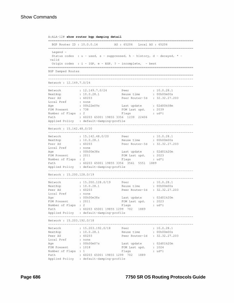
Show Commands
A:ALA-12# show router bgp damping detail =============================================================================== BGP Router ID : 10.0.0.14 AS : 65206 Local AS : 65206=============================================================================== Legend - Status codes : u - used, s - suppressed, h - history, d - decayed, * - valid Origin codes : i - IGP, e - EGP, ? - incomplete, - best===============================================================================BGP Damped Routes===============================================================================-------------------------------------------------------------------------------Network : 12.149.7.0/24-------------------------------------------------------------------------------Network : 12.149.7.0/24 Peer : 10.0.28.1NextHop : 10.0.28.1 Reuse time : 00h00m00sPeer AS : 60203 Peer Router-Id : 32.32.27.203Local Pref : noneAge : 00h22m09s Last update : 02d00h58mFOM Present : 738 FOM Last upd. : 2039Number of Flaps : 2 Flags : ud*iPath : 60203 65001 19855 3356 1239 22406Applied Policy : default-damping-profile-------------------------------------------------------------------------------Network : 15.142.48.0/20-------------------------------------------------------------------------------Network : 15.142.48.0/20 Peer : 10.0.28.1NextHop : 10.0.28.1 Reuse time : 00h00m00sPeer AS : 60203 Peer Router-Id : 32.32.27.203Local Pref : noneAge : 00h00m38s Last update : 02d01h20mFOM Present : 2011 FOM Last upd. : 2023Number of Flaps : 2 Flags : ud*iPath : 60203 65001 19855 3356 3561 5551 1889Applied Policy : default-damping-profile-------------------------------------------------------------------------------Network : 15.200.128.0/19-------------------------------------------------------------------------------Network : 15.200.128.0/19 Peer : 10.0.28.1NextHop : 10.0.28.1 Reuse time : 00h00m00sPeer AS : 60203 Peer Router-Id : 32.32.27.203Local Pref : noneAge : 00h00m38s Last update : 02d01h20mFOM Present : 2011 FOM Last upd. : 2023Number of Flaps : 2 Flags : ud*iPath : 60203 65001 19855 1299 702 1889Applied Policy : default-damping-profile-------------------------------------------------------------------------------Network : 15.203.192.0/18-------------------------------------------------------------------------------Network : 15.203.192.0/18 Peer : 10.0.28.1NextHop : 10.0.28.1 Reuse time : 00h00m00sPeer AS : 60203 Peer Router-Id : 32.32.27.203Local Pref : noneAge : 00h00m07s Last update : 02d01h20mFOM Present : 1018 FOM Last upd. : 1024Number of Flaps : 1 Flags : ud*iPath : 60203 65001 19855 1299 702 1889Applied Policy : default-damping-profile
Page 686 7750 SR OS Routing Protocols Guide

BGP
-------------------------------------------------------------------------------A:ALA-12#A:ALA-12# show router bgp damping 15.203.192.0/18 detail=============================================================================== BGP Router ID : 10.0.0.14 AS : 65206 Local AS : 65206=============================================================================== Legend - Status codes : u - used, s - suppressed, h - history, d - decayed, * - valid Origin codes : i - IGP, e - EGP, ? - incomplete, - best===============================================================================BGP Damped Routes 15.203.192.0/18===============================================================================-------------------------------------------------------------------------------Network : 15.203.192.0/18-------------------------------------------------------------------------------Network : 15.203.192.0/18 Peer : 10.0.28.1NextHop : 10.0.28.1 Reuse time : 00h00m00sPeer AS : 60203 Peer Router-Id : 32.32.27.203Local Pref : noneAge : 00h00m42s Last update : 02d01h20mFOM Present : 2003 FOM Last upd. : 2025Number of Flaps : 2 Flags : ud*iPath : 60203 65001 19855 3356 702 1889Applied Policy : default-damping-profile-------------------------------------------------------------------------------Paths : 1===============================================================================A:ALA-12#
A:ALA-12# show router bgp damping suppressed detail =============================================================================== BGP Router ID : 10.0.0.14 AS : 65206 Local AS : 65206=============================================================================== Legend - Status codes : u - used, s - suppressed, h - history, d - decayed, * - valid Origin codes : i - IGP, e - EGP, ? - incomplete, - best===============================================================================BGP Damped Routes (Suppressed)===============================================================================-------------------------------------------------------------------------------Network : 15.142.48.0/20-------------------------------------------------------------------------------Network : 15.142.48.0/20 Peer : 10.0.28.1NextHop : 10.0.28.1 Reuse time : 00h29m22sPeer AS : 60203 Peer Router-Id : 32.32.27.203Local Pref : noneAge : 00h01m28s Last update : 02d01h20mFOM Present : 2936 FOM Last upd. : 3001Number of Flaps : 3 Flags : siPath : 60203 65001 19855 3356 702 1889Applied Policy : default-damping-profile-------------------------------------------------------------------------------Network : 15.200.128.0/19-------------------------------------------------------------------------------Network : 15.200.128.0/19 Peer : 10.0.28.1NextHop : 10.0.28.1 Reuse time : 00h29m22sPeer AS : 60203 Peer Router-Id : 32.32.27.203Local Pref : none
7750 SR OS Routing Protocols Guide Page 687

Show Commands
Age : 00h01m28s Last update : 02d01h20mFOM Present : 2936 FOM Last upd. : 3001Number of Flaps : 3 Flags : siPath : 60203 65001 19855 3356 702 1889Applied Policy : default-damping-profile-------------------------------------------------------------------------------Network : 15.203.240.0/20-------------------------------------------------------------------------------Network : 15.203.240.0/20 Peer : 10.0.28.1NextHop : 10.0.28.1 Reuse time : 00h29m22sPeer AS : 60203 Peer Router-Id : 32.32.27.203Local Pref : noneAge : 00h01m28s Last update : 02d01h20mFOM Present : 2936 FOM Last upd. : 3001Number of Flaps : 3 Flags : siPath : 60203 65001 19855 3356 702 1889Applied Policy : default-damping-profile-------------------------------------------------------------------------------Network : 15.206.0.0/17-------------------------------------------------------------------------------Network : 15.206.0.0/17 Peer : 10.0.28.1NextHop : 10.0.28.1 Reuse time : 00h29m22sPeer AS : 60203 Peer Router-Id : 32.32.27.203Local Pref : noneAge : 00h01m28s Last update : 02d01h20mFOM Present : 2936 FOM Last upd. : 3001Number of Flaps : 3 Flags : siPath : 60203 65001 19855 3356 702 1889Applied Policy : default-damping-profile-------------------------------------------------------------------------------A:ALA-12#
group
Syntax group [name] [detail]
Context show>router>bgp
Description This command displays group information for a BGP peer group. This command can be entered with or without parameters.
When this command is entered without a group name, information about all peer groups displays.
When the command is issued with a specific group name, information only pertaining to that specific peer group displays.
The ‘State’ field displays the BGP group’s operational state. Valid states are:
Up — BGP global process is configured and running.
Down — BGP global process is administratively shutdown and not running.
Disabled — BGP global process is operationally disabled. The process must be restarted by the operator.
Parameters name — Displays information for the BGP group specified.
detail — Displays detailed information.
Page 688 7750 SR OS Routing Protocols Guide

BGP
Output Standard and Detailed Group Output — The following table describes the standard and detailed command output fields for a BGP group.
Label Description
Group Displays the BGP group name.
Group Type No Type — Peer type not configured.
External — Peer type configured as external BGP peers.
Internal — Peer type configured as internal BGP peers.
State Disabled — The BGP peer group has been operationally disabled.
Down — The BGP peer group is operationally inactive.
Up — The BGP peer group is operationally active.
Peer AS The configured or inherited peer AS for the specified peer group.
Local AS The configured or inherited local AS for the specified peer group.
Local Address The configured or inherited local address for originating peering for the specified peer group.
Loop Detect The configured or inherited loop detect setting for the specified peer group.
Connect Retry The configured or inherited connect retry timer value.
Authentication None — No authentication is configured.
MD5 — MD5 authentication is configured.
Bfd Yes — BFD is enabled.
No — BFD is disabled.
Local Pref The configured or inherited local preference value.
MED Out The configured or inherited MED value assigned to advertised routes without a MED attribute.
Min Route Advt. The minimum amount of time that must pass between route updates for the same IP prefix.
Min AS Originate The minimum amount of time that must pass between updates for a route originated by the local router.
Multihop The maximum number of router hops a BGP connection can traverse.
Prefix Limit No Limit — No route limit assigned to the BGP peer group.
1 — 4294967295 — The maximum number of routes BGP can learn from a peer.
7750 SR OS Routing Protocols Guide Page 689

Show Commands
Passive Disabled — BGP attempts to establish a BGP connection with neighbor in the specified peer group.
Enabled — BGP will not actively attempt to establish a BGP con-nection with neighbor in the specified peer group.
Next Hop Self Disabled — BGP is not configured to send only its own IP address as the BGP nexthop in route updates to neighbors in the peer group.
Enabled — BGP sends only its own IP address as the BGP nexthop in route updates to neighbors in the specified peer group.
Aggregator ID 0 Disabled — BGP is not configured to set the aggregator ID to 0.0.0.0 in all originated route aggregates sent to the neighbor in the peer group.
Enabled — BGP is configured to set the aggregator ID to 0.0.0.0 in all originated route aggregates sent to the neighbor in the peer group.
Remove Private Disabled — BGP will not remove all private AS numbers from the AS path attribute in updates sent to the neighbor in the peer group.
Enabled — BGP removes all private AS numbers from the AS path attribute in updates sent to the neighbor in the peer group.
Damping Disabled — The peer group is configured not to dampen route flaps.
Enabled — The peer group is configured to dampen route flaps.
Export Policy The configured export policies for the peer group.
Import Policy The configured import policies for the peer group.
Hold Time The configured hold time setting.
Keep Alive The configured keepalive setting.
Cluster Id The configured route reflector cluster ID.
None — No cluster ID has been configured
Client Reflect Disabled — The BGP route reflector will not reflect routes to this neighbor.
Enabled — The BGP route reflector is configured to reflect routes to this neighbor.
NLRI The type of NLRI information that the specified peer group can accept.
Unicast — IPv4 unicast routing information can be carried.
Preference The configured route preference value for the peer group.
Label Description (Continued)
Page 690 7750 SR OS Routing Protocols Guide

BGP
Sample Output
A:ALA-12# show router bgp group===============================================================================BGP Groups -------------------------------------------------------------------------------Group : To_AS_40000 -------------------------------------------------------------------------------Description : Not AvailableGroup Type : No Type State : Up Peer AS : 40000 Local AS : 65206 Local Address : n/a Loop Detect : Ignore Export Policy : direct2bgp Hold Time : 90 Keep Alive : 30 Cluster Id : None Client Reflect : Enabled NLRI : Unicast Preference : 170 List of Peers- 10.0.0.1 : To_Jukebox- 10.0.0.12 : Not Available- 10.0.0.13 : Not Available- 10.0.0.14 : To_SR1- 10.0.0.15 : To_H-215 Total Peers : 5 Established : 2 ===============================================================================A:ALA-12#
Sample Detailed Output
A:ALA-12# show router bgp group detail===============================================================================BGP Groups (detail)-------------------------------------------------------------------------------Group : To_AS_40000 -------------------------------------------------------------------------------Description : Not AvailableGroup Type : No Type State : Up Peer AS : 40000 Local AS : 65206 Local Address : n/a Loop Detect : Ignore Connect Retry : 20 Authentication : None Local Pref : 100 MED Out : 0 Multihop : 0 (Default) Min Route Advt. : 30 Min AS Originate : 15 Prefix Limit : No Limit Passive : Disabled Next Hop Self : Disabled Aggregator ID 0 : Disabled Remove Private : Disabled Damping : Disabled Export Policy : direct2bgp
List of Peers A list of BGP peers configured under the peer group.
Total Peers The total number of peers configured under the peer group.
Established The total number of peers that are in an established state.
Label Description (Continued)
7750 SR OS Routing Protocols Guide Page 691

Show Commands
Hold Time : 90 Keep Alive : 30 Cluster Id : None Client Reflect : Enabled NLRI : Unicast Preference : 170 List of Peers- 10.0.0.1 : To_Jukebox- 10.0.0.12 : Not Available- 10.0.0.13 : Not Available- 10.0.0.14 : To_SR1- 10.0.0.15 : To_H-215 Total Peers : 5 Established : 2 ===============================================================================A:ALA-12#
A:SetupCLI>show>router>bgp# group===============================================================================BGP Group-------------------------------------------------------------------------------Group : bgp_group_1 34567890123456789012-------------------------------------------------------------------------------Description : Testing the length of the group value for the DESCRIPTION parameter of BGPGroup Type : No Type State : UpPeer AS : n/a Local AS : 100Local Address : n/a Loop Detect : IgnoreImport Policy : test i1 : test i2 : test i3 : test i4 : test i5 890123456789012345678901Export Policy : test e1 : test e2 : test e3 : test e4 : test e5 890123456789012345678901Hold Time : 120 Keep Alive : 30Cluster Id : None Client Reflect : DisabledNLRI : Unicast Preference : 101TTL Security : Disabled Min TTL Value : n/aGraceful Restart : Disabled Stale Routes Time: n/aAuth key chain : n/a Bfd Enabled : Yes
List of Peers- 3.3.3.3 : Testing the length of the neighbor value for the DESCRIPTION parameter of BGPTotal Peers : 1 Established : 0-------------------------------------------------------------------------------Peer Groups : 1===============================================================================A:SetupCLI>show>router>bgp#
Page 692 7750 SR OS Routing Protocols Guide

BGP
neighbor
Syntax neighbor [ip-address [detail]]neighbor [as-number [detail]]neighbor ip-address [family [type mvpn-type]] filter1 [brief]neighbor ip-address [family] filter2 neighbor as-number [family] filter2 neighbor ip-address orf [filter3]neighbor ip-address graceful-restart
Context show>router>bgp
Description This command displays BGP neighbor information. This command can be entered with or without any parameters.
When this command is issued without any parameters, information about all BGP peers displays.
When the command is issued with a specific IP address or ASN, information regarding only that specific peer or peers with the same AS displays.
When either received-routes or advertised-routes is specified, then the routes received from or sent to the specified peer is listed (see second output example). Note: This information is not available by SNMP.
When either history or suppressed is specified, then the routes learned from those peers that either have a history or are suppressed (respectively) are listed.
The ‘State’ field displays the BGP peer’s protocol state. In additional to the standard protocol states, this field can also display the ‘Disabled’ operational state which indicates the peer is operationally disabled and must be restarted by the opeartor.
Parameters ip-address — Display information for the specified IP address.
Values ipv4-address: a.b.c.d (host bits must be 0)ipv6-address: x:x:x:x:x:x:x:x[-interface])
x:x:x:x:x:x:d.d.d.d[-interface]x: [0 — FFFF]Hd: [0 — 255]Dinterface: 32 characters maximum, mandatory for link localaddresses.
as-number — Display information for the specified AS number.
Values 1 — 65535
family — Specify the type of routing information to be distributed by this peer group.
Values ipv4 — Displays only those BGP peers that have the IPv4 family enable and not those capable of exchanging IP-VPN routes.vpn-ipv4 — Displays the content of the multicast routing table.ipv6 — Displays the BGP peers that are IPv6 capable.mcast-ipv4 — Displays the BGP peers that are mcast-ipv4 capable.
7750 SR OS Routing Protocols Guide Page 693

Show Commands
filter1 — Display information for the specified IP address.
Values received-routes — Displays the number of routes received from this peer.advertised-routes — Displays the number of routes advertised by this peer.history — Displays statistics for dampened routes.suppressed — Displays the number of paths from this peer that have been suppressed by damping.detail — Displays detailed information pertaining to filter1.
filter2 — Display information for the specified AS number.
Values history — Display statistics for dampened routes.suppressed — Display the number of paths from this peer that have been suppressed by damping.detail — Displays detailed information pertaining to filter2
filter3 — Displays path information for the specified IP address.
Values send — Displays the number of paths sent to this peer.receive — Displays the number of paths received from this peer.
brief — Displays information in a brief format. This parameter is only supported with received-routes and advertised-routes.
orf — Displays outbound route filtering for the BGP instance. ORF (Outbound Route Filtering) is used to inform a neighbor of targets (using target-list) that it is willing to receive. This mechanism helps lessen the update exchanges between neighbors and saves CPU cycles to process routes that could have been received from the neighbor only to be dropped/ignored.
graceful-restart — Displays neighbors configured for graceful restart.
Output Standard and Detailed Neighbor — The following table describes the standard and detailed command output fields for a BGP neighbor.
Label Description
Peer The IP address of the configured BGP peer.
Group The BGP peer group to which this peer is assigned.
Peer AS The configured or inherited peer AS for the peer group.
Peer Address The configured address for the BGP peer.
Peer Port The TCP port number used on the far-end system.
Local AS The configured or inherited local AS for the peer group.
Local Address The configured or inherited local address for originating peering for the peer group.
Local Port The TCP port number used on the local system.
Peer Type External — Peer type configured as external BGP peers.
Internal — Peer type configured as internal BGP peers.
Page 694 7750 SR OS Routing Protocols Guide

BGP
Bfd Yes — BFD is enabled.
No — BFD is disabled.
State Idle — The BGP peer is not accepting connections.
Active — BGP is listening for and accepting TCP connections from this peer.
Connect — BGP is attempting to establish a TCP connections from this peer.
Open Sent — BGP has sent an OPEN message to the peer and is waiting for an OPEN message from the peer.
Open Confirm — BGP has received a valid OPEN message from the peer and is awaiting a KEEPALIVE or NOTIFICATION.
Established — BGP has successfully established a peering and is exchanging routing information.
Last State Idle — The BGP peer is not accepting connections.
Active — BGP is listening for and accepting TCP connections from this peer.
Connect — BGP is attempting to establish a TCP connections from this peer.
Open Sent — BGP has sent an OPEN message to the peer and is waiting for an OPEN message from the peer.
Open Confirm — BGP has received a valid OPEN message from the peer and is awaiting a KEEPALIVE or NOTIFICATION.
Last Event start — BGP has initialized the BGP neighbor.
stop — BGP has disabled the BGP neighbor.
open — BGP transport connection opened.
close — BGP transport connection closed.
openFail — BGP transport connection failed to open.
error — BGP transport connection error.
connectRetry — Connect retry timer expired.
holdTime — Hold time timer expired.
keepAlive — Keepalive timer expired.
recvOpen — Receive an OPEN message.
Label Description (Continued)
7750 SR OS Routing Protocols Guide Page 695

Show Commands
revKeepalive — Receive a KEEPALIVE message.
recvUpdate — Receive an UPDATE message.
recvNotify — Receive a NOTIFICATION message.
None — No events have occurred.
Last Error Displays the last BGP error and subcode to occur on the BGP neigh-bor.
Connect Retry The configured or inherited connect retry timer value.
Local Pref. The configured or inherited local preference value.
Min Route Advt. The minimum amount of time that must pass between route updates for the same IP prefix.
Min AS Originate The minimum amount of time that must pass between updates for a route originated by the local router.
Multihop The maximum number of router hops a BGP connection can traverse.
Damping Disabled — BGP neighbor is configured not to dampen route flaps.
Enabled — BGP neighbor is configured to dampen route flaps.
Loop Detect Ignore — The BGP neighbor is configured to ignore routes with an AS loop.
Drop — The BGP neighbor is configured to drop the BGP peering if an AS loop is detected.
Off — AS loop detection is disabled for the neighbor.
MED Out The configured or inherited MED value assigned to advertised routes without a MED attribute.
Authentication None — No authentication is configured.
MD5 — MD5 authentication is configured.
Next Hop Self Disabled — BGP is not configured to send only its own IP address as the BGP nexthop in route updates to the specified neighbor.
Enabled — BGP will send only its own IP address as the BGP nexthop in route updates to the neighbor.
AggregatorID Zero Disabled — The BGP Neighbor is not configured to set the aggre-gator ID to 0.0.0.0 in all originated route aggregates.
Enabled — The BGP Neighbor is configured to set the aggregator ID to 0.0.0.0 in all originated route aggregates.
Label Description (Continued)
Page 696 7750 SR OS Routing Protocols Guide

BGP
Remove Private Disabled — BGP will not remove all private AS numbers from the AS path attribute, in updates sent to the specified neighbor.
Enabled — BGP will remove all private AS numbers from the AS path attribute, in updates sent to the specified neighbor.
Passive Disabled — BGP will actively attempt to establish a BGP connec-tion with the specified neighbor.
Enabled — BGP will not actively attempt to establish a BGP con-nection with the specified neighbor.
Prefix Limit No Limit — No route limit assigned to the BGP peer group.
1 — 4294967295 — The maximum number of routes BGP can learn from a peer.
Hold Time The configured hold time setting.
Keep Alive The configured keepalive setting.
Active Hold Time The negotiated hold time, if the BGP neighbor is in an established state.
Active Keep Alive The negotiated keepalive time, if the BGP neighbor is in an established state.
Cluster Id The configured route reflector cluster ID.
None — No cluster ID has been configured.
Client Reflect Disabled — The BGP route reflector is configured not to reflect routes to this neighbor.
Enabled — The BGP route reflector is configured to reflect routes to this neighbor.
Preference The configured route preference value for the peer group.
Num of Flaps The number of route flaps in the neighbor connection..
Recd. Prefixes The number of routes received from the BGP neighbor.
Active Prefixes The number of routes received from the BGP neighbor and active in the forwarding table.
Recd. Paths The number of unique sets of path attributes received from the BGP neighbor.
Suppressed Paths The number of unique sets of path attributes received from the BGP neighbor and suppressed due to route damping.
Input Queue The number of BGP messages to be processed.
Label Description (Continued)
7750 SR OS Routing Protocols Guide Page 697
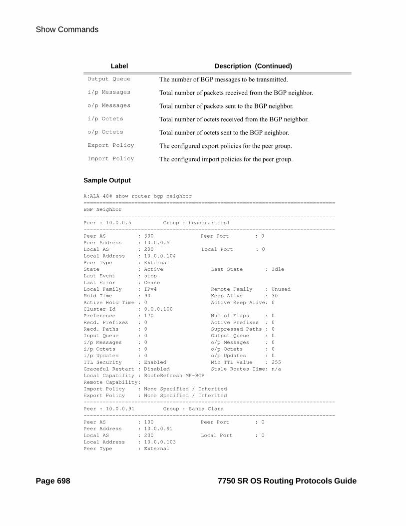
Show Commands
Sample Output
A:ALA-48# show router bgp neighbor===============================================================================BGP Neighbor-------------------------------------------------------------------------------Peer : 10.0.0.5 Group : headquarters1-------------------------------------------------------------------------------Peer AS : 300 Peer Port : 0Peer Address : 10.0.0.5 Local AS : 200 Local Port : 0Local Address : 10.0.0.104 Peer Type : ExternalState : Active Last State : IdleLast Event : stopLast Error : CeaseLocal Family : IPv4 Remote Family : UnusedHold Time : 90 Keep Alive : 30Active Hold Time : 0 Active Keep Alive: 0Cluster Id : 0.0.0.100Preference : 170 Num of Flaps : 0Recd. Prefixes : 0 Active Prefixes : 0Recd. Paths : 0 Suppressed Paths : 0Input Queue : 0 Output Queue : 0i/p Messages : 0 o/p Messages : 0i/p Octets : 0 o/p Octets : 0i/p Updates : 0 o/p Updates : 0TTL Security : Enabled Min TTL Value : 255Graceful Restart : Disabled Stale Routes Time: n/aLocal Capability : RouteRefresh MP-BGPRemote Capability:Import Policy : None Specified / InheritedExport Policy : None Specified / Inherited-------------------------------------------------------------------------------Peer : 10.0.0.91 Group : Santa Clara-------------------------------------------------------------------------------Peer AS : 100 Peer Port : 0Peer Address : 10.0.0.91 Local AS : 200 Local Port : 0Local Address : 10.0.0.103 Peer Type : External
Output Queue The number of BGP messages to be transmitted.
i/p Messages Total number of packets received from the BGP neighbor.
o/p Messages Total number of packets sent to the BGP neighbor.
i/p Octets Total number of octets received from the BGP neighbor.
o/p Octets Total number of octets sent to the BGP neighbor.
Export Policy The configured export policies for the peer group.
Import Policy The configured import policies for the peer group.
Label Description (Continued)
Page 698 7750 SR OS Routing Protocols Guide

BGP
State : Connect Last State : ActiveLast Event : openFailLast Error : CeaseLocal Family : IPv4 Remote Family : UnusedHold Time : 90 Keep Alive : 30Active Hold Time : 0 Active Keep Alive: 0Cluster Id : 0.0.0.100Preference : 170 Num of Flaps : 0Recd. Prefixes : 0 Active Prefixes : 0Recd. Paths : 0 Suppressed Paths : 0Input Queue : 0 Output Queue : 0i/p Messages : 0 o/p Messages : 1i/p Octets : 0 o/p Octets : 0i/p Updates : 0 o/p Updates : 0TTL Security : Disabled Min TTL Value : n/aGraceful Restart : Disabled Stale Routes Time: n/aLocal Capability : RouteRefresh MP-BGPRemote Capability:Import Policy : None Specified / InheritedExport Policy : None Specified / Inherited...-------------------------------------------------------------------------------A:ALA-48#
A:ALA-48# show router 2 bgp neighbor 10.20.1.3===============================================================================BGP Neighbor===============================================================================Peer : 10.20.1.3Group : 1-------------------------------------------------------------------------------Peer AS : 100 Peer Port : 49725Peer Address : 10.20.1.3Local AS : 100 Local Port : 179Local Address : 10.20.1.2Peer Type : InternalState : Established Last State : EstablishedLast Event : recvKeepAliveLast Error : CeaseLocal Family : IPv4Remote Family : IPv4Hold Time : 3 Keep Alive : 1Active Hold Time : 3 Active Keep Alive : 1Cluster Id : NonePreference : 170 Num of Flaps : 0Recd. Paths : 1IPv4 Recd. Prefixes : 11 IPv4 Active Prefixes : 10IPv4 Suppressed Pfxs : 0 VPN-IPv4 Suppr. Pfxs : 0VPN-IPv4 Recd. Pfxs : 0 VPN-IPv4 Active Pfxs : 0Mc IPv4 Recd. Pfxs. : 0 Mc IPv4 Active Pfxs. : 0Mc IPv4 Suppr. Pfxs : 0 IPv6 Suppressed Pfxs : 0IPv6 Recd. Prefixes : 0 IPv6 Active Prefixes : 0Input Queue : 0 Output Queue : 0i/p Messages : 471 o/p Messages : 473i/p Octets : 3241 o/p Octets : 3241i/p Updates : 4 o/p Updates : 4TTL Security : Disabled Min TTL Value : n/aAdvertise Inactive : Disabled Peer Tracking : DisabledAdvertise Label : None
7750 SR OS Routing Protocols Guide Page 699

Show Commands
Auth key chain : eta_keychain1Local Capability : RouteRefresh MP-BGPRemote Capability : RouteRefresh MP-BGPImport Policy : None Specified / InheritedExport Policy : static2bgp-------------------------------------------------------------------------------Neighbors : 1===============================================================================A:ALA-48#
A:ALA-12# show router bgp neighbor 10.0.0.11 orf===============================================================================BGP Neighbor 10.0.0.11 ORF===============================================================================Send List (Automatic)-------------------------------------------------------------------------------target:65535:10target:65535:20===============================================================================A:ALA-12
A:ALA-22 show router bgp neighbor 10.0.0.1 orf===============================================================================BGP Neighbor 10.0.0.1 ORF===============================================================================Receive List-------------------------------------------------------------------------------target:65535:10target:65535:20===============================================================================A:ALA-22
Sample Detailed Output
A:ALA-12# show router bgp neighbor detail===============================================================================BGP Neighbor (detail)-------------------------------------------------------------------------------Peer : 10.0.0.15 Group : To_AS_40000-------------------------------------------------------------------------------Peer AS : 65205 Peer Port : 0 Peer Address : 10.0.0.15 Local AS : 65206 Local Port : 0 Local Address : 10.0.0.16 Peer Type : External State : Active Last State : Connect Last Event : openFail Last Error : Hold Timer ExpireConnect Retry : 20 Local Pref. : 100 Min Route Advt. : 30 Min AS Orig. : 15 Damping : Disabled Loop Detect : Ignore MED Out : No MED Out Authentication : None Next Hop Self : Disabled AggregatorID Zero: Disabled Remove Private : Disabled Passive : Disabled Prefix Limit : No Limit Hold Time : 90 Keep Alive : 30
Page 700 7750 SR OS Routing Protocols Guide

BGP
Active Hold Time : 0 Active Keep Alive: 0 Cluster Id : None Client Reflect : Enabled Preference : 170 Num of Flaps : 0 Recd. Prefixes : 0 Active Prefixes : 0 Recd. Paths : 0 Suppressed Paths : 0 Input Queue : 0 Output Queue : 0 i/p Messages : 0 o/p Messages : 0 i/p Octets : 0 o/p Octets : 0 i/p Updates : 0 o/p Updates : 0 Export Policy : direct2bgp ===============================================================================A:ALA-12#
*A:SetupCLI>show>router>bgp# neighbor===============================================================================BGP Neighbor===============================================================================Peer : 3.3.3.3Group : bgp_group_1 34567890123456789012-------------------------------------------------------------------------------Peer AS : 20 Peer Port : 0Peer Address : 3.3.3.3Local AS : 100 Local Port : 0Local Address : 0.0.0.0Peer Type : InternalState : Active Last State : IdleLast Event : stopLast Error : CeaseLocal Family : IPv4Remote Family : UnusedHold Time : 10 Keep Alive : 30Active Hold Time : 0 Active Keep Alive : 0Cluster Id : 2.2.3.4Preference : 101 Num of Flaps : 0Recd. Paths : 0IPv4 Recd. Prefixes : 0 IPv4 Active Prefixes : 0IPv4 Suppressed Pfxs : 0 VPN-IPv4 Suppr. Pfxs : 0VPN-IPv4 Recd. Pfxs : 0 VPN-IPv4 Active Pfxs : 0Mc IPv4 Recd. Pfxs. : 0 Mc IPv4 Active Pfxs. : 0Mc IPv4 Suppr. Pfxs : 0 IPv6 Suppressed Pfxs : 0IPv6 Recd. Prefixes : 0 IPv6 Active Prefixes : 0Input Queue : 0 Output Queue : 0i/p Messages : 0 o/p Messages : 0i/p Octets : 0 o/p Octets : 0i/p Updates : 0 o/p Updates : 0TTL Security : Disabled Min TTL Value : n/aGraceful Restart : Enabled Stale Routes Time : 360Advertise Inactive : Disabled Peer Tracking : EnabledAdvertise Label : None Bfd Enabled : Yes Auth key chain : n/aLocal Capability : RouteRefresh MP-BGPRemote Capability :Import Policy : test i1 : test i2 : test i3 : test i4 : test i5 890123456789012345678901Export Policy : test e1
7750 SR OS Routing Protocols Guide Page 701

Show Commands
: test e2 : test e3 : test e4 : test e5 890123456789012345678901-------------------------------------------------------------------------------Neighbors : 1===============================================================================
Advertised and Received Routes Ouptut — The following table describes the command output for both the standard and detailed information for a neighor.
Label Description
BGP Router ID The local BGP router ID.
AS The configured autonomous system number.
Local AS The configured local AS setting. If not configured, then it is the same value as the AS.
Flag u — used
s — suppressed
h — history
d — decayed
* — valid
i — igp
e — egp
? — incomplete
> — best
Network Route IP prefix and mask length for the route.
Next Hop BGP nexthop for the route.
LocalPref BGP local preference path attribute for the route.
MED BGP Multi-Exit Discriminator (MED) path attribute for the route.
AS Path The BGP AS path for the route.
Sample Output
A:ALA-12# show router bgp neighbor 10.0.0.16 received-routes=============================================================================== BGP Router ID : 10.0.0.16 AS : 65206 Local AS : 65206 =============================================================================== Legend - Status codes : u - used, s - suppressed, h - history, d - decayed, * - valid
Page 702 7750 SR OS Routing Protocols Guide

BGP
Origin codes : i - IGP, e - EGP, ? - incomplete, > - best===============================================================================BGP Neighbor===============================================================================Flag Network Nexthop LocalPref MED As-Path -------------------------------------------------------------------------------? 10.0.0.16/32 10.0.0.16 100 none No As-Path ? 10.0.6.0/24 10.0.0.16 100 none No As-Path ? 10.0.8.0/24 10.0.0.16 100 none No As-Path ? 10.0.12.0/24 10.0.0.16 100 none No As-Path ? 10.0.13.0/24 10.0.0.16 100 none No As-Path ? 10.0.204.0/24 10.0.0.16 100 none No As-Path ===============================================================================A:ALA-12#
A:core_east# show router bgp neighbor 10.193.0.10 graceful-restart============================================================================BGP Neighbor 10.193.0.10 Graceful Restart============================================================================Graceful Restart locally configured for peer: EnabledPeer's Graceful Restart feature : EnabledNLRI(s) that peer supports restart for : IPv4-Unicast IPv4-MPLS IPv4-VPNNLRI(s) that peer saved forwarding for : IPv4-Unicast IPv4-MPLS IPv4-VPNNLRI(s) that restart is negotiated for : NoneNLRI(s) of received end-of-rib markers : IPv4-UnicastNLRI(s) of all end-of-rib markers sent : IPv4-UnicastRestart time locally configured for peer : 120 secondsRestart time requested by the peer : 390 secondsTime stale routes from peer are kept for : 360 secondsGraceful restart status on the peer : Not currently being helpedNumber of Restarts : 328Last Restart at : 08/20/2006 12:22:06============================================================================A:core_east#
next-hop
Syntax next-hop [ family] [ip-address] [detail]
Context show>router>bgp
Description Displays BGP next-hop information.
Parameters family — Specify the type of routing information to be distributed by the BGP instance.
Values ipv4 — Displays only those BGP peers that have the IPv4 family enable and not those capable of exchanging IP-VPN routes.vpn-ipv4 — Displays the BGP peers that are IP-VPN capable.ipv6 — Displays the BGP peers that are IPv6 capable.mcast-ipv4 — Displays the BGP peers that are mcast-ipv4 capable.
ip-address — Displays the next hop information for the specified IP address.
Values ipv4-address: a.b.c.d (host bits must be 0)ipv6-address: x:x:x:x:x:x:x:x (eight 16-bit pieces)
7750 SR OS Routing Protocols Guide Page 703

Show Commands
x:x:x:x:x:x:d.d.d.dx [0 — FFFF]Hd [0 — 255]D
detail — Display the longer, more detailed version of the output.
Output Show Next-Hop Output — The following table describes the command output fields for a BGP next hop.
Label Description
BGP ID The local BGP router ID.
AS The configured autonomous system number.
Local AS The configured local AS setting. If not configured, then the value is the same as the AS.
Next Hop The next-hop address.
Resolving Prefix Displays the prefix of the best next hop.
Owner Displays the routing protocol used to derive the best next hop.
Preference Displays the BGP preference attribute for the routes.
Reference Count Displays the number of routes using the resolving prefix.
Resolved Next Hop The IP address of the next hop.
Sample Output
*A:Dut-C# show router bgp next-hop=============================================================================== BGP Router ID:10.20.1.3 AS:5000 Local AS:5000===============================================================================
===============================================================================BGP Next Hop===============================================================================Next Hop Pref Owner Resolving Prefix Metric Resolved Next Hop Ref. Count-------------------------------------------------------------------------------10.20.1.1 7 RSVP 10.20.1.1/32 1000 10.10.2.1 210.20.1.2 7 RSVP 10.20.1.2/32 1000 10.10.3.2 210.20.1.4 7 RSVP 10.20.1.4/32 1000 10.10.11.4 2-------------------------------------------------------------------------------Next Hops : 3
Page 704 7750 SR OS Routing Protocols Guide

BGP
A:ALA-49>show>router>bgp# next-hop 192.168.2.194------------------------------------------------------------------------------- BGP Router ID : 10.10.10.104 AS : 200 Local AS : 200===============================================================================BGP Next Hop===============================================================================Next Hop Resolving Owner Preference Reference Resolved Prefix Count Next Hop-------------------------------------------------------------------------------A:ALA-49>show>router>bgp# next-hop 10.10.10.104
paths
Syntax paths
Context show>router>bgp
Description This command displays a summary of BGP path attributes.
Output Show Path Output — The following table describes the command output fields for a BGP path.
Label Description
BGP Router ID The local BGP router ID.
AS The configured autonomous system number.
Local AS The configured local AS setting. If not configured, then the value is the same as the AS.
Path The AS path attribute.
Origin EGP — The NLRI is learned by an EGP protocol.
IGP — The NLRI is interior to the originating AS.
INCOMPLETE — NLRI was learned another way.
Next Hop The advertised BGP nexthop.
MED The Multi-Exit Discriminator value.
Local Preference The local preference value. This value is used if the BGP route arrives from a BGP peer without the Local Pref attribute set. It is overridden by any value set via a route policy.
Refs The number of routes using a specified set of path attributes.
ASes The number of autonomous system numbers in the AS path attribute.
Segments The number of segments in the AS path attribute.
Flags EBGP-learned — Path attributes learned by an EBGP peering.
IBGP-Learned — Path attributes learned by an IBGP peering.
7750 SR OS Routing Protocols Guide Page 705

Show Commands
Sample Output
=============================================================================== BGP Router ID : 10.0.0.14 AS : 65206 Local AS : 65206 ===============================================================================BGP Paths===============================================================================Path: 60203 65001 19855 3356 15412 -------------------------------------------------------------------------------Origin : IGP Next Hop : 10.0.28.1 MED : 60203 Local Preference : none Refs : 4 ASes : 5 Segments : 1 Flags : EBGP-learnedAggregator : 15412 62.216.140.1-------------------------------------------------------------------------------Path: 60203 65001 19855 3356 1 1236 1236 1236 1236 -------------------------------------------------------------------------------Origin : IGP Next Hop : 10.0.28.1 MED : 60203 Local Preference : none Refs : 2 ASes : 9 Segments : 1 Flags : EBGP-learned
route-target
Syntax route-target
Context show>router>bgp
Description This command displays a summary of route-target.
Sample Output
*A:Dut-D# show router bgp routes route-target=============================================================================== BGP Router ID:10.20.1.4 AS:100 Local AS:100===============================================================================
Aggregator The route aggregator ID.
Community The BGP community attribute list.
Originator ID The originator ID path attribute value.
Cluster List The route reflector cluster list.
Label Description (Continued)
Page 706 7750 SR OS Routing Protocols Guide

BGP
Legend - Status codes : u - used, s - suppressed, h - history, d - decayed, * - valid Origin codes : i - IGP, e - EGP, ? - incomplete, > - best, b - backup ===============================================================================BGP RT Constrain Routes===============================================================================Flag Route Target LocalPref MED Nexthop As-Path-------------------------------------------------------------------------------u*? 0:0:0/0 None 0 10.10.9.6 106 106-------------------------------------------------------------------------------Routes : 1===============================================================================
routes
Syntax routes [family] [brief]routes [family] prefix [detail | longer | hunt [brief]]routes family prefix [detail | longer | hunt [brief]]routes [family [type mvpn-type]] community comm-idroutes [family [type mvpn-type]] aspath-regex reg-exroutes mvpn-ipv4 type mvpn-type {rd rd | originator-ip ip-address | source-ip ip-address | group-ip ip-address | source-as as-number} [hunt| detail]routes [family [l2vpn-type]] [brief]routes [family [l2vpn-type]] community comm-idroutes [family [l2vpn-type]] aspath-regex reg-exroutes l2-vpn l2vpn-type {[rd rd] | [siteid site-id] | [veid veid] [offset vpls-base-offset ]}routes mdt-safi [rd rd] [grp-address mcast-grp-address] [brief]routes ms-pw [rd rd] [aii-type2 aii-type2] [brief]routes flow-ipv4
Context show>router>bgp
Description This command displays BGP route information.
When this command is issued without any parameters, then the entire BGP routing table displays.
When this command is issued with an IP prefix/mask or IP address, then the best match for the parameter displays.
Parameters family — Specify the type of routing information to be distributed by the BGP instance.
Values ipv4 — Displays only those BGP peers that have the IPv4 family enable and not those capable of exchanging IP-VPN routes.vpn-ipv4 — Displays the BGP peers that are IP-VPN capable.ipv6 — Displays the BGP peers that are IPv6 capable.mcast-ipv4 — Displays the BGP peers that are mcast-ipv4 capable.
received — Specifies to show the BGP routes received from the neighbor,
7750 SR OS Routing Protocols Guide Page 707

Show Commands
prefix — Specifies the type of routing information to display.
Values Syntax: <rd>|[<rd>:]<ip-prefix[/ip-prefix-length]>rd {<ip-addr:comm-val>|<2byte-asnumber:ext-comm-val>|<4byte-
asnumber:comm-val>}comm-val [0..65535]2byte-asnumber [0..65535]ext-comm-val [0..4294967295]4byte-asnumber asn1.asn2 (two 2-byte pieces)
asn1 - [1..65535]asn2 - [0..65535]
ip-address a.b.c.dipv4-prefix a.b.c.dipv4-prefix-le [0..32]
ipv6-prefix[/pref* ipv6-prefix x:x:x:x:x:x:x:x (eight 16-bit pieces) x:x:x:x:x:x:d.d.d.d x: [0 — FFFF]Hd: [0 — 255]D
prefix-length 0 — 128
filter — Specifies route criteria.
Values hunt Displays entries for the specified route in the RIB-In, RIB-Out, and RTM.longer Displays the specified route and subsets of the route.detail Display the longer, more detailed version of the output.
aspath-regex “reg-exp” — Displays all routes with an AS path matching the specified regular expression reg-exp.
community comm.-id — Displays all routes with the specified BGP community.
Values [as-number1:comm-val1 | ext-comm | well-known-comm]ext-comm type:{ip-address:comm-val1 | as-number1:comm-val2 | as-
number2:comm-val1}as-number1 0 — 65535comm-val1 0 — 65535type target, originip-address a.b.c.dcomm-val2 0 — 4294967295as-number2 0 — 4294967295well-known-comm no-export, no-export-subconfed, no-advertise
brief — Provides a summarized display of the set of peers to which a BGP route is advertised.
rd — Specifies the route distinguisher.
Values ip-addr:comm-va 2byte-asnumber:ext-comm-val 4byte-asnumber:comm-val}
veid — Specifies a two byte identifier that represents the local bridging instance in a VPLS and is advertised through the BGP NLRI. This value must be lower than or equal to the max-ve-id.
Values 0 — 4294967295
Page 708 7750 SR OS Routing Protocols Guide

BGP
vpls-base-offset — Specifies a two byte identifier advertised through the NLRI that is used to indicate which VE-ID should use the advertised NLRI at the receiving PE according to the following rule: if the offset<= local VE-ID <= offset+VBS-1 (VBS = virtual block size = 8 in our implementation) then the NLRI is processed. Otherwise it is ignored. The NLRI with this offset is generated as soon as the first VE-ID value between (offset, offset + VBS-1) is advertised in the network.
Values 0 — 4294967295
site-id — Specifies a two byte identifier usually employed for the BGP multi-homing solution. It identifies the BGP multi-homing site associated with one or a set of objects (SAP(s), pseudowire (s) or combination). The site-id must be identical between the two PEs carrying the connection to the access device multi-homed to the PEs.
Values 0 — 4294967295
l2vpn-type — Specifies a 12-byte Virtual Switch Instance identifier (VSI-ID) type.
Values bgp-ad, bgp-vpls, multi-homing
ms-pw [rd rd] [aii-type2 aii-type2] [brief] — Displays routes for ms-pw family.
Output BGP Route — The following table describes the command output fields for BGP routes.
Label Description
BGP Router ID The local BGP router ID.
AS The configured autonomous system number.
Local AS The configured local AS setting. If not configured, then the value is the same as the AS.
Route Dist. Displays the route distinguisher identifier attached to routes that distinguishes the VPN it belongs.
VPN Label Displays the label generated by the PE's label manager.
Network The IP prefix and mask length.
Nexthop The BGP nexthop.
From The advertising BGP neighbor’s IP address.
Res. Nexthop The resolved nexthop.
Local Pref. The local preference value. This value is used if the BGP route arrives from a BGP peer without the Local Pref attribute set. It is overridden by any value set via a route policy.
Flag u — used
s — suppressed
7750 SR OS Routing Protocols Guide Page 709

Show Commands
Sample Output
*A:Dut-C# show router bgp routes l2-vpn detail
========================================================================BGP Router ID:10.20.1.3 AS:1000 Local AS:1000
========================================================================
h —history
d — decayed
* — valid
i — igp
e — egp
? — incomplete
> — best
Aggregator AS The aggregator AS value.none — Aggregator AS attributes are not present.
Aggregator The aggregator attribute value.none — Aggregator attributes are not present.
Atomic Aggr. Atomic — The atomic aggregator flag is set.
Not Atomic — The atomic aggregator flag is not set.
MED The MED metric value.
none — MED metrics are present.
Community The BGP community attribute list.
Cluster The route reflector cluster list.
Originator Id The originator ID path attribute value.
none — The originator ID attribute is not present.
Peer Router Id The router ID of the advertising router.
AS-Path The BGP AS path attribute.
VPRN Imported Displays the VPRNs where a particular BGP-VPN received route has been imported and installed.
Label Description (Continued)
Page 710 7750 SR OS Routing Protocols Guide

BGP
Legend -
Status codes : u - used, s - suppressed, h - history, d - decayed, * - valid
Origin codes : i - IGP, e - EGP, ? - incomplete, > - best, b - backup
========================================================================
BGP L2VPN Routes
========================================================================
Route Type : AutoDiscovery
Route Dist. : 10.20.1.1:1
Prefix : 10.20.1.1
Nexthop : 10.20.1.1
From : 10.20.1.1
Res. Nexthop : n/a
Local Pref. : 100 Interface Name : NotAvailable
Aggregator AS : None Aggregator : None
Atomic Aggr. : Not Atomic MED : 0
AIGP Metric : Not Atomic
Community : target:4455:4455 target:1.20.30.40:6543
l2-vpn/vrf-imp:100.1.200.1:65535
Cluster : No Cluster Members
Originator Id : None Peer Router Id : 10.20.1.1
Flags : Used Valid Best IGP
Route Source : Internal
AS-Path : No As-Path
------------------------------------------------------------------------
PMSI Tunnel Attribute :
Tunnel-type : RSVP-TE P2MP LSP Flags : Leaf not required
MPLS Label : 0
P2MP-ID : 1001 Tunnel-ID : 61440
Extended-Tunne*: 10.20.1.1
7750 SR OS Routing Protocols Guide Page 711

Show Commands
*A:Dut-C# show router bgp routes hunt 1.1.1.1/32 =============================================================================== BGP Router ID:10.20.1.3 AS:5000 Local AS:5000=============================================================================== Legend - Status codes : u - used, s - suppressed, h - history, d - decayed, * - valid Origin codes : i - IGP, e - EGP, ? - incomplete, > - best
===============================================================================BGP IPv4 Routes===============================================================================-------------------------------------------------------------------------------RIB In Entries-------------------------------------------------------------------------------Network : 1.1.1.1/32Nexthop : 10.20.1.1From : 10.20.1.1Res. Nexthop : 10.20.1.1 (RSVP LSP: 1)Local Pref. : 100 Interface Name : ip-10.10.2.3Aggregator AS : None Aggregator : NoneAtomic Aggr. : Not Atomic MED : NoneCommunity : No Community MembersCluster : No Cluster MembersOriginator Id : None Peer Router Id : 10.20.1.1Flags : Used Valid Best IncompleteAS-Path : No As-Path
-------------------------------------------------------------------------------RIB Out Entries--------------------------------------------------------------------------------------------------------------------------------------------------------------Routes : 1===============================================================================
A:ALA-12>config>router>bgp# show router bgp routes family ipv4=============================================================================== BGP Router ID : 10.10.10.103 AS : 200 Local AS : 200=============================================================================== Legend - Status codes : u - used, s - suppressed, h - history, d - decayed, * - valid Origin codes : i - IGP, e - EGP, ? - incomplete, > - best===============================================================================BGP Routes===============================================================================Flag Network Nexthop LocalPref MED VPN Label As-Path-------------------------------------------------------------------------------No Matching Entries Found===============================================================================A:ALA-12>config>router>bgp#
A:ALA-12>config>router>bgp# show router bgp routes 13.1.0.0/24 de =============================================================================== BGP Router ID : 10.128.0.161 AS : 65535 Local AS : 65535 ===============================================================================
Page 712 7750 SR OS Routing Protocols Guide

BGP
Legend - Status codes : u - used, s - suppressed, h - history, d - decayed, * - valid Origin codes : i - IGP, e - EGP, ? - incomplete, > - best =============================================================================== BGP Routes =============================================================================== Original Attributes Network : 13.1.0.0/24 Nexthop : 10.20.1.20 Route Dist. : 10070:100 VPN Label : 152784 From : 10.20.1.20 Res. Nexthop : 10.130.0.2 Local Pref. : 100 Aggregator AS: none Aggregator : none Atomic Aggr. : Not Atomic MED : none Community : target:10070:1Cluster : No Cluster Members Originator Id: None Peer Router Id : 10.20.1.20 Flags : Used Valid Best IGP AS-Path : 10070 {14730}
Modified Attributes
Network : 13.1.0.0/24 Nexthop : 10.20.1.20 Route Dist. : 10001:100 VPN Label : 152560From : 10.20.1.20 Res. Nexthop : 10.130.0.2 Local Pref. : 100 Aggregator AS: none Aggregator : none Atomic Aggr. : Not Atomic MED : none Community : target:10001:1 Cluster : No Cluster Members Originator Id: None Peer Router Id : 10.20.1.20 Flags : Used Valid Best IGP AS-Path : No As-Path ------------------------------------------------------------------------------- ...=============================================================================== A:ALA-12>config>router>bgp#
A:SR-12# show router bgp routes 100.0.0.0/30 hunt =============================================================================== BGP Router ID : 10.20.1.1 AS : 100Local AS : 100 =============================================================================== Legend - Status codes : u - used, s - suppressed, h - history, d - decayed, * - valid Origin codes : i - IGP, e - EGP, ? - incomplete, > - best===============================================================================BGP Routes===============================================================================RIB In Entries-------------------------------------------------------------------------------Network : 100.0.0.0/30Nexthop : 10.20.1.2Route Dist. : 10.20.1.2:1 VPN Label : 131070 From : 10.20.1.2Res. Nexthop : 10.10.1.2Local Pref. : 100 Interface Name: to-sr7 Aggregator AS : none Aggregator : none Atomic Aggr. : Not Atomic MED : noneCommunity : target:10.20.1.2:1Cluster : No Cluster Members
7750 SR OS Routing Protocols Guide Page 713

Show Commands
Originator Id : None Peer Router Id: 10.20.1.2Flags : Used Valid Best IGP AS-Path : No As-PathVPRN Imported : 1 2 10 12-------------------------------------------------------------------------------RIB Out Entries-------------------------------------------------------------------------------Routes : 1===============================================================================A:SR-12#
*A:praragon-sim1# /show router bgp routes mvpn-ipv4=============================================================================== BGP Router ID:10.20.1.3 AS:200 Local AS:200=============================================================================== Legend - Status codes : u - used, s - suppressed, h - history, d - decayed, * - valid Origin codes : i - IGP, e - EGP, ? - incomplete, > - best===============================================================================BGP MVPN-IPv4 Routes===============================================================================Flag RouteType OriginatorIP LocalPref MED RD SourceAS VPNLabel Nexthop SourceIP As-Path GroupIP-------------------------------------------------------------------------------u*>i Intra-Ad 10.20.1.4 100 0 1:1 - - 10.20.1.4 - No As-Path -u*>i Source-Ad - 100 0 1:1 - - 10.20.1.4 130.100.1.2 No As-Path 227.0.0.0u*>i Source-Join - 100 0 1:1 200 - 10.20.1.4 150.100.1.2 No As-Path 226.0.0.0-------------------------------------------------------------------------------Routes : 3===============================================================================*A:praragon-sim1#
*A:praragon-sim1# show router bgp routes mvpn-ipv4 brief=============================================================================== BGP Router ID:10.20.1.3 AS:200 Local AS:200=============================================================================== Legend - Status codes : u - used, s - suppressed, h - history, d - decayed, * - valid Origin codes : i - IGP, e - EGP, ? - incomplete, > - best===============================================================================BGP MVPN-IPv4 Routes===============================================================================Flag RouteType OriginatorIP SourceIP RD SourceAS GroupIP-------------------------------------------------------------------------------u*>i Intra-Ad 10.20.1.4 -
Page 714 7750 SR OS Routing Protocols Guide

BGP
1:1 - -u*>i Source-Ad - 130.100.1.2 1:1 - 227.0.0.0u* >i Source-Join - 150.100.1.2 1:1 200 226.0.0.0-------------------------------------------------------------------------------Routes : 3===============================================================================*A:praragon-sim1#
*A:praragon-sim1# show router bgp routes mvpn-ipv4 type source-join source-as 200 source-ip 150.100.1.2 group-ip 226.0.0.0 detail=============================================================================== BGP Router ID:10.20.1.3 AS:200 Local AS:200=============================================================================== Legend - Status codes : u - used, s - suppressed, h - history, d - decayed, * - valid Origin codes : i - IGP, e - EGP, ? - incomplete, > - best ===============================================================================BGP MVPN-IPv4 Routes===============================================================================Route Type : Source-JoinRoute Dist. : 1:1Source AS : 200Source IP : 150.100.1.2Group IP : 226.0.0.0Nexthop : 10.20.1.4From : 10.20.1.4Res. Nexthop : 0.0.0.0Local Pref. : 100 Interface Name : NotAvailableAggregator AS : None Aggregator : NoneAtomic Aggr. : Not Atomic MED : 0Community : target:10.20.1.3:2Cluster : No Cluster MembersOriginator Id : None Peer Router Id : 10.20.1.4Flags : Used Valid Best IGPAS-Path : No As-Path -------------------------------------------------------------------------------Routes : 1===============================================================================*A:praragon-sim1#
*A:Dut-C# show router bgp routes ms-pw =============================================================================== BGP Router ID:10.20.1.3 AS:100 Local AS:100 =============================================================================== Legend - Status codes : u - used, s - suppressed, h - history, d - decayed, * - valid Origin codes : i - IGP, e - EGP, ? - incomplete, > - best, b - backup
===============================================================================BGP MSPW Routes===============================================================================Flag Network RD Nexthop AII-Type2/Preflen
7750 SR OS Routing Protocols Guide Page 715

Show Commands
As-Path -------------------------------------------------------------------------------? 3:10.20.1.3 100:3 10.20.1.5 3:10.20.1.3:0/64 200 100 ? 3:10.20.1.3 100:4 10.20.1.5 3:10.20.1.3:0/64 200 100 u*>? 6:10.20.1.6 100:6 10.20.1.5 6:10.20.1.6:0/64 200 300 400 -------------------------------------------------------------------------------Routes : 3===============================================================================
summary
Syntax summary [all]summary [family family] [neighbor ip-address]
Context show>router>bgp
Description This command displays a summary of BGP neighbor information.
If confederations are not configured, that portion of the output will not display.
The “State” field displays the global BGP operational state. The valid values are:
Up — BGP global process is configured and running.
Down — BGP global process is administratively shutdown and not running.
Disabled — BGP global process is operationally disabled. The process must be restarted by the operator.
For example, if a BGP peer is operationally disabled, then the state in the summary table shows the state ‘Disabled’
Parameters family — Specify the type of routing information to be distributed by the BGP instance.
Values ipv4 — Displays only those BGP peers that have the IPv4 family enabled.vpn-ipv4 — Displays the BGP peers that are IP-VPN capable.ipv6 — Displays the BGP peers that are IPv6 capable.mcast-ipv4 — Displays the BGP peers that are mcast-ipv4 capable.
neighbor ip-address — Clears damping information for entries received from the BGP neighbor.
Values ipv4-address: a.b.c.d ipv6-address: x:x:x:x:x:x:x:x (eight 16-bit pieces)
x:x:x:x:x:x:d.d.d.dx: [0 — FFFF]Hd: [0 — 255]D
Page 716 7750 SR OS Routing Protocols Guide

BGP
Output BGP Summary Output — The following table describes the command output fields for a BGP summary.
Label Description
BGP Router ID The local BGP router ID.
AS The configured autonomous system number.
Local AS The configured local AS setting. If not configured, then the value is the same as the AS.
BGP Admin State Down — BGP is administratively disabled.
Up — BGP is administratively enabled.
BGP Oper State Down — BGP is operationally disabled.
Up — BGP is operationally enabled.
Bfd Yes — BFD is enabled.
No — BFD is disabled.
Confederation AS The configured confederation AS.
Member Confedera-tions
The configured members of the BGP confederation.
Number of Peer Groups
The total number of configured BGP peer groups.
Number of Peers The total number of configured BGP peers.
Total BGP Active Routes
The total number of BGP routes used in the forwarding table.
Total BGP Routes The total number of BGP routes learned from BGP peers.
Total BGP Paths The total number of unique sets of BGP path attributes learned from BGP peers.
Total Path Memory Total amount of memory used to store the path attributes.
Total Suppressed Routes
Total number of suppressed routes due to route damping.
Total History Routes
Total number of routes with history due to route damping.
Total Decayed Routes
Total number of decayed routes due to route damping.
Total VPN Peer Groups
The total number of configured VPN peer groups.
Total VPN Peers The total number of configured VPN peers.
Total VPN Local Rts
The total number of configured local VPN routes.
7750 SR OS Routing Protocols Guide Page 717

Show Commands
Sample Output
A:Dut-C# show router bgp summary neighbor 3FFE::A0A:1064=============================================================================== BGP Router ID : 10.20.1.3 AS : 100 Local AS : 100===============================================================================BGP Admin State : Up BGP Oper State : UpNumber of Peer Groups : 4 Number of Peers : 5Total BGP Paths : 8 Total Path Memory : 1212Total BGP Active Rts. : 0 Total BGP Rts. : 0Total Supressed Rts. : 0 Total Hist. Rts. : 0Total Decay Rts. : 0 Total VPN Peer Groups : 0 Total VPN Peers : 0Total VPN Local Rts. : 0Total VPN Remote Rts. : 0 Total VPN Remote Active Rts.: 0Total VPN Supp. Rts. : 0 Total VPN Hist. Rts. : 0Total VPN Decay Rts. : 0 Total IPv6 Remote Rts. : 5 Total IPv6 Rem. Active Rts. : 4===============================================================================
Total VPN Remote Rts
The total number of configured remote VPN routes.
Total VPN Remote Active Rts.
The total number of active remote VPN routes used in the forwarding table.
Total VPN Supp.Rts.
Total number of suppressed VPN routes due to route damping.
Total VPN Hist. Rts.
Total number of VPN routes with history due to route damping.
Total VPN Decay Rts.
Total number of decayed routes due to route damping.
Neighbor BGP neighbor address.
AS(Neighbor)
BGP neighbor autonomous system number.
PktRcvd Total number of packets received from the BGP neighbor.
PktSent Total number of packets sent to the BGP neighbor.
InQ The number of BGP messages to be processed.
OutQ The number of BGP messages to be transmitted.
Up/Down The amount of time that the BGP neighbor has either been established or not established depending on its current state.
State|Recv/Actv/Sent
The BGP neighbor’s current state (if not established) or the number of received routes, active routes and sent routes (if established).
Label Description (Continued)
Page 718 7750 SR OS Routing Protocols Guide

BGP
BGP Summary===============================================================================Neighbor AS PktRcvd InQ Up/Down State|Rcv/Act/Sent (IPv4) PktSent OutQ Rcv/Act/Sent (VpnIPv4) Rcv/Act/Sent (IPv6) Rcv/Act/Sent (MCastIPv4)-------------------------------------------------------------------------------3FFE::A0A:1064 103 489 0 00h40m28s IPv4 Incapable 569 0 VPN-IPv4 Incapable 1/1/3 MCAST-IPv4 Incapable===============================================================================A:Dut-C#
A:Dut-C# show router bgp summary neighbor 10.20.1.4 family ipv6=============================================================================== BGP Router ID : 10.20.1.3 AS : 100 Local AS : 100===============================================================================BGP Admin State : Up BGP Oper State : UpNumber of Peer Groups : 4 Number of Peers : 5Total BGP Paths : 8 Total Path Memory : 1212Total BGP Active Rts. : 0 Total BGP Rts. : 0Total Supressed Rts. : 0 Total Hist. Rts. : 0Total Decay Rts. : 0 Total VPN Peer Groups : 0 Total VPN Peers : 0Total VPN Local Rts. : 0Total VPN Remote Rts. : 0 Total VPN Remote Active Rts.: 0Total VPN Supp. Rts. : 0 Total VPN Hist. Rts. : 0Total VPN Decay Rts. : 0 Total IPv6 Remote Rts. : 5 Total IPv6 Rem. Active Rts. : 4===============================================================================BGP IPv6 Summary===============================================================================Neighbor AS PktRcvd PktSent InQ OutQ Up/Down State|Recv/Actv/Sent-------------------------------------------------------------------------------10.20.1.4 100 554 572 0 0 00h41m27s 1/0/3===============================================================================A:Dut-C#
A:SetupCLI>show>router# bgp summary=============================================================================== BGP Router ID : 21.3.4.5 AS : 35012 Local AS : 100===============================================================================BGP Admin State : Up BGP Oper State : UpConfederation AS : 40000Member Confederations : 35012 65205 65206 65207 65208Rapid Withdrawal : DisabledBfd Enabled : Yes
Number of Peer Groups : 1 Number of Peers : 1Total BGP Paths : 3 Total Path Memory : 396
7750 SR OS Routing Protocols Guide Page 719

Show Commands
Total BGP Active Rts. : 0 Total BGP Rts. : 0Total Supressed Rts. : 0 Total Hist. Rts. : 0Total Decay Rts. : 0
Total VPN Peer Groups : 1 Total VPN Peers : 1Total VPN Local Rts. : 0Total VPN Remote Rts. : 0 Total VPN Remote Active Rts.: 0Total VPN Supp. Rts. : 0 Total VPN Hist. Rts. : 0Total VPN Decay Rts. : 0
Total IPv6 Remote Rts. : 0 Total IPv6 Rem. Active Rts. : 0===============================================================================BGP Summary===============================================================================Neighbor AS PktRcvd InQ Up/Down State|Rcv/Act/Sent (IPv4) PktSent OutQ Rcv/Act/Sent (VpnIPv4) Rcv/Act/Sent (IPv6) Rcv/Act/Sent (MCastIPv4)-------------------------------------------------------------------------------3.3.3.3 20 0 0 01h55m56s Active 0 0===============================================================================A:SetupCLI>show>router#
mvpn
Syntax mvpn
Context show>router
Description This command displays Multicast VPN related information.
Sample Output
*A:praragon-sim1# show router 100 mvpn===============================================================================MVPN 100 configuration data===============================================================================i-pmsi : 224.100.201.101 ssm admin status : Uphello-interval : 30 seconds hello-multiplier : 35 * 0.1three-way-hello : Disabled tracking support : Disabled s-pmsi range : 0.0.0.0/0 data-delay-interval: 3 secondsjoin-tlv-packing : N/A signaling : Bgpvrf-import : N/Avrf-export : N/Avrf-target : N/A===============================================================================*A:praragon-sim1#
Page 720 7750 SR OS Routing Protocols Guide

BGP
Clear Commands
damping
Syntax damping [[ip-prefix/ip-prefix-length] [neighbor ip-address]] | [group name]
Context clear>router>bgp
Description This command clears or resets the route damping information for received routes.
Parameters ip-prefix/ip-prefix-length — Clears damping information for entries that match the IP prefix and prefix length.
Values ipv4-prefix: a.b.c.d (host bits must be 0)ipv4-prefix-length: 0 — 32ipv6-prefix: x:x:x:x:x:x:x:x (eight 16-bit pieces)
x:x:x:x:x:x:d.d.d.dx: [0 — FFFF]Hd: [0 — 255]D
ipv6-prefix-length: 0 — 128
neighbor ip-address — Clears damping information for entries received from the BGP neighbor.
Values ipv4-address: a.b.c.d ipv6-address: x:x:x:x:x:x:x:x (eight 16-bit pieces)
x:x:x:x:x:x:d.d.d.dx: [0 — FFFF]Hd: [0 — 255]Dinterface: 32 chars maximum, mandatory
Values for link local addresses
group name — Clears damping information for entries received from any BGP neighbors in the peer group.
Values 32 characters maximum
flap-statistics
Syntax flap-statistics [[ip-prefix/mask] [neighbor ip-address]] | [group group-name] | [regex reg-exp] | [policy policy-name]
Context clear>router>bgp
Description This command clears route flap statistics.
Parameters ip-prefix/mask — Clears route flap statistics for entries that match the specified IP prefix and mask length.
Values ip-prefix: a.b.c.d (host bits must be 0)mask: 0 — 32
7750 SR OS Routing Protocols Guide Page 721

Clear Commands
neighbor ip-address — Clears route flap statistics for entries received from the specified BGP neighbor.
Values ipv4-address: a.b.c.dipv6-address: x:x:x:x:x:x:x:x (eight 16-bit pieces)
x:x:x:x:x:x:d.d.d.dx: [0 — FFFF]Hd: [0 — 255]D
group group-name — Clears route flap statistics for entries received from any BGP neighbors in the specified peer group.
regex reg-exp — Clears route flap statistics for all entries which have the regular expression and the AS path that matches the regular expression.
policy policy-name — Clears route flap statistics for entries that match the specified route policy.
neighbor
Syntax neighbor {ip-address | as as-number | external | all} [soft | soft-inbound]neighbor{ip-address | as as-number | external | all} statisticsneighbor ip-address end-of-rib
Context clear>router>bgp
Description This command resets the specified BGP peer or peers. This can cause existing BGP connections to be shutdown and restarted.
Parameters ip-address — Resets the BGP neighbor with the specified IP address.
Values ipv4-address: a.b.c.dipv6-address: x:x:x:x:x:x:x:x[-interface]
x:x:x:x:x:x:d.d.d.d[-interface]x: [0 — FFFF]Hd: [0 — 255]Dinterface: 32 characters maximum, mandatory for link localaddresses
as as-number — Resets all BGP neighbors with the specified peer AS.
Values 1 — 65535
external — Resets all EBGP neighbors.
all — Resets all BGP neighbors.
soft — The specified BGP neighbor(s) re-evaluates all routes in the Local-RIB against the configured export policies.
soft-inbound — The specified BGP neighbor(s) re-evaluates all routes in the RIB-In against the configures import policies.
statistics — The BGP neighbor statistics.
end-of-rib — Clears the routing information base (RIB).This command applies when 7750 SR is helping the BGP neighbor through a BGP graceful restart. When the clear router bgp neighbor command is issued
Page 722 7750 SR OS Routing Protocols Guide

BGP
without the end-of-rib option and the neighbor is in the process of restarting, stale routes from the neighbor will be retained until the stale-routes-time is reached or else the neighbor exits graceful restart. When the command is issued with the end-of-rib option, stale routes from the neighbor are deleted immediately and graceful restart procedures are aborted.
protocol
Syntax protocol
Context clear>router>bgp
Description Resets the entire BGP protocol.
7750 SR OS Routing Protocols Guide Page 723

Debug Commands
Debug Commands
events
Syntax events [neighbor ip-address | group name]no events
Context debug>router>bgp
Description This command logs all events changing the state of a BGP peer.
Parameters neighbor ip-address — Debugs only events affecting the specified BGP neighbor.
Values ipv4-address: a.b.c.d (host bits must be 0)ipv6-address: x:x:x:x:x:x:x:x [-interface] (eight 16-bit pieces)
x:x:x:x:x:x:d.d.d.d [-interface]x [0 — FFFF]Hd [0 — 255]Dinterface: 32 characters maximum, mandatory for link localaddresses
group name — Debugs only events affecting the specified peer group and associated neighbors.
graceful-restart
Syntax graceful-restart [neighbor ip-address | group name]no graceful-restart
Context debug>router>bgp
Description This command enables debugging for BGP graceful-restart.
The no form of the command disables the debugging.
Parameters neighbor ip-address — Debugs only events affecting the specified BGP neighbor.
Values ipv4-address: a.b.c.d (host bits must be 0)ipv6-address: x:x:x:x:x:x:x:x[-interface]
x:x:x:x:x:x:d.d.d.d[-interface]x: [0 — FFFF]Hd: [0 — 255]Dinterface: 32 characters maximum, mandatory for link localaddresses)
group name — Debugs only events affecting the specified peer group and associated neighbors.
Page 724 7750 SR OS Routing Protocols Guide

BGP
keepalive
Syntax keepalive [neighbor ip-addr | group name]no keepalive
Context debug>router>bgp
Description This command decodes and logs all sent and received keepalive messages in the debug log.
Parameters neighbor ip-address — Debugs only events affecting the specified BGP neighbor.
Values ipv4-address: a.b.c.d (host bits must be 0)ipv6-address: x:x:x:x:x:x:x:x[-interface]
x:x:x:x:x:x:d.d.d.d[-interface]x: [0 — FFFF]Hd: [0 — 255]Dinterface: 32 characters maximum, mandatory for link localaddresses)
group name — Debugs only events affecting the specified peer group and associated neighbors.
notification
Syntax notification [neighbor ip-address | group name]no notification
Context debug>router>bgp
Description This command decodes and logs all sent and received notification messages in the debug log.
Parameters neighbor ip-address — Debugs only events affecting the specified BGP neighbor.
Values ipv4-address: a.b.c.d (host bits must be 0)ipv6-address: x:x:x:x:x:x:x:x[-interface]
x:x:x:x:x:x:d.d.d.d[-interface]x: [0 — FFFF]Hd: [0 — 255]Dinterface: 32 characters maximum, mandatory for link localaddresses)
group name — Debugs only events affecting the specified peer group and associated neighbors.
open
Syntax open [neighbor ip-address | group name]no open
Context debug>router>bgp
Description This command decodes and logs all sent and received open messages in the debug log.
7750 SR OS Routing Protocols Guide Page 725

Debug Commands
Parameters neighbor ip-address — Debugs only events affecting the specified BGP neighbor.
Values ipv4-address: a.b.c.d (host bits must be 0)ipv6-address: x:x:x:x:x:x:x:x[-interface]
x:x:x:x:x:x:d.d.d.d[-interface]x: [0 — FFFF]Hd: [0 — 255]Dinterface: 32 characters maximum, mandatory for link localaddresses)
group name — Debugs only events affecting the specified peer group and associated neighbors.
outbound-route-filtering
Syntax [no] outbound-route-filtering
Context debug>router>bgp
Description This command enables debugging for for all BGP outbound route filtering (ORF) packets. ORF is used to inform a neighbor of targets (using target-list) that it is willing to receive.
packets
Syntax packets [neighbor ip-address | group name]packets
Context debug>router>bgp
Description This command decodes and logs all sent and received BGP packets in the debug log.
Parameters neighbor ip-address — Debugs only events affecting the specified BGP neighbor.
Values ipv4-address: a.b.c.d (host bits must be 0)ipv6-address: x:x:x:x:x:x:x:x[-interface]
x:x:x:x:x:x:d.d.d.d[-interface]x: [0 — FFFF]Hd: [0 — 255]Dinterface: 32 characters maximum, mandatory for link localaddresses)
group name — Debugs only events affecting the specified peer group and associated neighbors.
Page 726 7750 SR OS Routing Protocols Guide

BGP
route-refresh
Syntax route-refresh [neighbor ip-address | group name]no route-refresh
Context debug>router>bgp
Description Thic command enables and disables debugging for BGP route-refresh.
Parameters neighbor ip-address — Debugs only events affecting the specified BGP neighbor.
Values ipv4-address: a.b.c.d (host bits must be 0)ipv6-address: x:x:x:x:x:x:x:x[-interface]
x:x:x:x:x:x:d.d.d.d[-interface]x: [0 — FFFF]Hd: [0 — 255]Dinterface: 32 characters maximum, mandatory for link localaddresses)
group name — Debugs only events affecting the specified peer group and associated neighbors.
rtm
Syntax rtm [neighbor ip-address | group name]no rtm
Context debug>router>bgp
Description This command logs RTM changes in the debug log.
Parameters neighbor ip-address — Debugs only events affecting the specified BGP neighbor.
Values ipv4-address: a.b.c.d (host bits must be 0)ipv6-address: x:x:x:x:x:x:x:x[-interface]
x:x:x:x:x:x:d.d.d.d[-interface]x: [0 — FFFF]Hd: [0 — 255]Dinterface: 32 characters maximum, mandatory for link localaddresses)
group name — Debugs only events affecting the specified peer group and associated neighbors.
socket
Syntax socket [neighbor ip-address | group name]no socket
Context debug>router>bgp
Description This command logs all TCP socket events to the debug log.
7750 SR OS Routing Protocols Guide Page 727

Debug Commands
Parameters neighbor ip-address — Debugs only events affecting the specified BGP neighbor.
Values ipv4-address: a.b.c.d (host bits must be 0)ipv6-address: x:x:x:x:x:x:x:x[-interface]
x:x:x:x:x:x:d.d.d.d[-interface]x: [0 — FFFF]Hd: [0 — 255]Dinterface: 32 characters maximum, mandatory for link localaddresses)
group name — Debugs only events affecting the specified peer group and associated neighbors.
timers
Syntax timers [neighbor ip-address | group name]no timers
Context debug>router>bgp
Description This command logs all BGP timer events to the debug log.
Parameters neighbor ip-address — Debugs only events affecting the specified BGP neighbor.
Values ipv4-address: a.b.c.d (host bits must be 0)ipv6-address: x:x:x:x:x:x:x:x[-interface]
x:x:x:x:x:x:d.d.d.d[-interface]x: [0 — FFFF]Hd: [0 — 255]Dinterface: 32 characters maximum, mandatory for link localaddresses)
group name — Debugs only events affecting the specified peer group and associated neighbors.
update
Syntax update [neighbor ip-address | group name]no update
Context debug>router>bgp
Description This command decodes and logs all sent and received update messages in the debug log.
Parameters neighbor ip-address — Debugs only events affecting the specified BGP neighbor.
Values ipv4-address: a.b.c.d (host bits must be 0)ipv6-address: x:x:x:x:x:x:x:x[-interface]
x:x:x:x:x:x:d.d.d.d[-interface]x: [0 — FFFF]Hd: [0 — 255]D
Page 728 7750 SR OS Routing Protocols Guide

BGP
interface: 32 characters maximum, mandatory for link localaddresses)
group name — Debugs only events affecting the specified peer group and associated neighbors.
7750 SR OS Routing Protocols Guide Page 729

Debug Commands
Page 730 7750 SR OS Routing Protocols Guide

Route Policies
In This Chapter
This chapter provides information about configuring route policies.
Topics in this chapter include:
• Configuring Route Policies on page 732
Policy Statements on page 733
Default Action Behavior on page 734
BGP and OSPF Route Policy Support on page 742
BGP Route Policies on page 742
Re-advertised Route Policies on page 744
Triggered Policies on page 744
When to Use Route Policies on page 746
• Route Policy Configuration Process Overview on page 747
• Configuration Notes on page 748
7750 SR OS Routing Protocols Guide Page 731

Configuring Route Policies
Configuring Route Policies
Alcatel-Lucent’s 7750 SR OS supports two databases for routing information. The routing database is composed of the routing information learned by the routing protocols. The forwarding database is composed of the routes actually used to forward traffic through a router. In addition, link state databases are maintained by interior gateway protocols (IGPs) such as IS-IS and OSPF.
Routing protocols calculate the best route to each destination and place these routes in a forwarding table. The routes in the forwarding table are used to forward routing protocol traffic, sending advertisements to neighbors and peers.
A routing policy can be configured that will not place routes associated with a specific origin in the routing table. Those routes will not be used to forward data packets to the intended destinations and the routes are not advertised by the routing protocol to neighbors and peers.
Routing policies control the size and content of the routing tables, the routes that are advertised, and the best route to take to reach a destination. Careful planning is essential to implement route policies that can affect the flow of routing information or packets in and traversing through the router. Before configuring and applying a route policy, develop an overall plan and strategy to accomplish your intended routing actions.
There are no default route policies. Each policy must be created explicitly and applied to a routing protocol or to the forwarding table. Policy parameters are modifiable.
Page 732 7750 SR OS Routing Protocols Guide

Route Policies
Policy Statements
Route policies contain policy statements containing ordered entries containing match conditions and actions you specify. The entries should be sequenced from the most explicit to least explicit. Packet forwarding and routing can be implemented according to your defined policies. Policy-based routing allows you to dictate where traffic can be routed, through specific paths, or whether to forward or drop the traffic. Route policies can match a given route policy entry and continue searching for other matches within either the same route policy or the next route policy.
The process can stop when the first complete match is found and executes the action defined in the entry, either to accept or reject packets that match the criteria or proceed to the next entry or the next policy. You can specify matching criteria based on source, destination, or particular properties of a route. Route policies can be constructed to support multiple stages to the evaluation and setting various route attributes. You can also provide more matching conditions by specifying criteria such as:
• Autonomous system (AS) path policy options — A combination of AS numbers and regular expression operators.
• Community list — A group sharing a common property. • Prefix list — A named list of prefixes. • To and From criteria — A route’s source and destination.
7750 SR OS Routing Protocols Guide Page 733

Configuring Route Policies
Default Action Behavior
The default action specifies how packets are to be processed when a policy related to the route is not explicitly configured. The following default actions are applied in the event that:
• A route policy does not specify a matching condition, all the routes being compared with the route policy are considered to be matches.
• A packet does not match any policy entries, then the next policy is evaluated. If a match does not occur then the last entry in the last policy is evaluated.
• If no default action is specified, the default behavior of the protocol controls whether the routes match or not.
If a default action is defined for one or more of the configured route policies, then the default action is handled as follows:
• The default action can be set to all available action states including accept, reject, next-entry, and next-policy.
• If the action states accept or reject, then the policy evaluation terminates and the appropriate result is returned.
• If a default action is defined and no matches occurred with the entries in the policy, then the default action is used.
• If a default action is defined and one or more matches occurred with the entries of the policy, then the default action is not used.
Denied IP Prefixes
The following IP address prefixes are not allowed by the routing protocols and the Route Table Manager and are not be populated within the forwarding table:
• 0.0.0.0/8 or longer
• 127.0.0.0/8 or longer
• 224.0.0.0/4 or longer
• 240.0.0.0/4 or longer
Any other prefixes that need to be filtered can be filtered explicitly using route policies.
Page 734 7750 SR OS Routing Protocols Guide

Route Policies
Controlling Route Flapping
Route damping is a controlled acceptance of unstable routes from BGP peers so that any ripple effect caused by route flapping across BGP AS border routers is minimized. The motive is to delay the use of unstable routes (flapping routes) to forward data and advertisements until the route stabilizes.
Alcatel-Lucent’s implementation of route damping is based on the following parameters:
• Figure of Merit — A route is assigned a Figure of Merit (FoM), which is proportional to the frequency of flaps. FoM should be able to characterize a route’s behavior over a period of time.
• Route flap — A route flap is not limited to the withdrawn route. It also applies to any change in the AS path or the next hop of a reachable route. A change in AS path or next hop indicates that the intermediate AS or the route-advertising peer is not suppressing flapping routes at the source or during the propagation. Even if the route is accepted as a stable route, the data packets destined to the route could experience unstable routing due to the unstable AS path or next hop.
• Suppress threshold — The threshold is a configured value that, when exceeded, the route is suppressed and not advertised to other peers. The state is considered to be down from the perspective of the routing protocol.
• Reuse threshold — When FoM value falls below a configured reuse threshold and the route is still reachable, the route is advertised to other peers. The FoM value decays exponentially after a route is suppressed. This requires the BGP implementation to decay thousands of routes from a misbehaving peer.
The two events that could trigger the route flapping algorithm are:
• Route flapping — If a route flap is detected within a configured maximum route flap history time, the route’s FoM is initialized and the route is marked as a potentially unstable route. Every time a route flaps, the FoM is increased and the route is suppressed if the FoM crosses the suppress threshold.
• Route reuse timer trigger — A suppressed route’s FoM decays exponentially. When it crosses the reuse threshold, the route is eligible for advertisement if it is still reachable.
If the route continues to flap, the FoM, with respect to time scale, looks like a sawtooth waveform with the exponential rise and decay of FoM. To control flapping, the following parameters can be configured:
• half-life — The half life value is the time, expressed in minutes, required for a route to remain stable in order for one half of the FoM value to be reduced. For example, if the half life value is 6 (minutes) and the route remains stable for 6 minutes, then the new FoM
7750 SR OS Routing Protocols Guide Page 735

Configuring Route Policies
value is 3. After another 6 minutes passes and the route remains stable, the new FoM value is 1.5.
• max-suppress — The maximum suppression time, expressed in minutes, is the maximum amount of time that a route can remain suppressed.
• suppress — If the FoM value exceeds the configured integer value, the route is suppressed for use or inclusion in advertisements.
• reuse — If the suppress value falls below the configured reuse value, then the route can be reused.
Page 736 7750 SR OS Routing Protocols Guide

Route Policies
Regular Expressions
The ability to perform a filter match on confederations in the AS-PATH is supported. This feature allows customers to configure match criteria for specific confederation sets and sequences within the AS path so that they can be filtered out before cluttering the service provider’s routing information base (RIB).
7750 SR OS uses regular expression strings to specify match criteria for:
• An AS path string; for example, “100 200 300”
• A community string; for example, “100:200” where 100 is the AS number, and 200 is the community-value.
• Any AS path beginning with a confederation SET or SEQ containing 65001 and 65002 only: for example “< 65001 65002 >.*”
• Any AS path containing a confederation SET or SEQ, regardless of the contents: for example, “.* <.*> .*”
A regular expression is expressed in terms of terms and operators. A term for an AS path regular expression is:
1. Regular expressions should always be enclosed in quotes.
2. An elementary term; for example, an AS number “200”
3. A range term composed of two elementary terms separated by the ‘-’ character like “200-300”.
4. The '.' dot wild-card character which matches any elementary term.
5. A regular expression enclosed in parenthesis “( )”.
6. A regular expression enclosed in square brackets used to specify a set of choices of ele-mentary or range terms; for example. [100-300 400] matches any AS number between 100 and 300 or the AS number 400.
A term for a community string regular expression is a string that is evaluated character by character and is composed of:
1. An elementary term which for a community string is any single digit like “4”.
2. A range term composed of two elementary terms separated by the ‘-’ character like “2-3”.
3. A colon ':' to delimit the AS number from the community value
4. The '.' dot wild-card character which matches any elementary term or ':'.
5. A regular expression enclosed in parenthesis “( )”.
7750 SR OS Routing Protocols Guide Page 737

Regular Expressions
6. A regular expression enclosed in square brackets used to specify a set of choices of ele-mentary or range terms; for example, [1-37] matches any single digit between 1 and 3 or the digit 7.
The regular expression OPERATORS are listed in Table 20.
Table 20: Regular Expression Operators
Operator Description
| Matches the term on alternate sides of the pipe.
* Matches multiple occurrences of the term.
? Matches 0 or 1 occurrence of the term.
+ Matches 1 or more occurrence of the term.
( ) Used to parenthesize so a regular expression is considered as one term.
[ ] Used to demarcate a set of elementary or range terms.
- Used between the start and end of a range.
{m,n} Matches least m and at most n repetitions of the term.
{m} Matches exactly m repetitions of the term.
{m,} Matches m or more repetitions of the term.
^ Matches the beginning of the string - only allowed for communities.
$ Matches the end of the string - only allowed for communities.
\ An escape character to indicate that the following character is a match criteria and not a grouping delimiter.
<> Matches any AS path numbers containing a confederation SET or SEQ.
Page 738 7750 SR OS Routing Protocols Guide

Route Policies
Examples of AS path and community string regular expressions are listed in Table 21.
Table 21: AS Path and Community Regular Expression Examples
AS Path to Match Criteria Regular Expression Example Matches
Null AS path nulla Null AS path
AS path is 11 11 11
AS path is 11 22 33 11 22 33 11 22 33
Zero or more occurrences of AS number 11 11* Null AS path 1111 1111 11 11 11 … 11
Path of any length that begins with AS numbers 11, 22, 33
11 22 33 .* 11 22 3311 22 33 400 500 600
Path of any length that ends with AS numbers 44, 55, 66 .* 44 55 66 44 55 66100 44 55 66100 200 44 55 66100 200 300 44 55 66100 200 300 … 44 55 66
One occurrence of the AS numbers 100 and 200, followed by one or more occurrences of the number 33
100 200 33+ 100 200 33100 200 33 33100 200 33 33 33100 200 33 33 33 … 33
One or more occurrences of AS number 11, followed by one or more occurrences of AS number 22, followed by one or more occurrences of AS number 33
11+ 22+ 33+ 11 22 33 11 11 22 33 11 11 22 22 3311 11 22 22 33 3311 … 11 22 … 22 33 …33
Path whose second AS number must be 11 or 22 (. 11) | (. 22) .*or. (11 | 22) .*
100 11200 22 300 400…
Path of length one or two whose second AS number might be 11 or 22
. (11 | 22)? 100200 11300 22
7750 SR OS Routing Protocols Guide Page 739

Regular Expressions
Path whose first AS number is 100 and second AS number is either 11 or 22
100 (11 | 22) .* 100 11 100 22 200 300
Either AS path 11, 22, or 33 [11 22 33] 1122 33
Range of AS numbers to match a single AS number 10-14 10 or 11 or 12 or 13 or 14
[10-12]* Null AS path 10 or 11 or 1210 10 or 10 11 or 10 1211 10 or 11 11 or 11 1212 10 or 12 11 or 12 12…
Zero or one occurrence of AS number 11 11? or 11{0,1} Null AS path11
One through four occurrences of AS number 11 11{1,4} 11 11 1111 11 1111 11 11 11
One through four occurrences of AS number 11 followed by one occurrence of AS number 22
11{1,4} 22 11 2211 11 22 11 11 11 2211 11 11 11 22
Path of any length, except nonexistent, whose second AS number can be anything, including nonexistent
. .* or . .{0,} 100100 20011 22 33 44 55
AS number is 100. Community value is 200. ^100:200$ 100:200
AS number is 11 or 22. Community value is any number. ^((11)|(22)):(.*)$
11:10022:10011:200…
AS number is 11. Community value is any number that starts with 1.
^11:(1.*)$ 11:111:10011:1100…
Table 21: AS Path and Community Regular Expression Examples (Continued)
AS Path to Match Criteria Regular Expression Example Matches
Page 740 7750 SR OS Routing Protocols Guide

Route Policies
AS number is any number. Community value is any number that ends with 1, 2, or 3.
^(.*):(.*[1-3])$
11:1100:2002333:55553…
AS number is 11 or 22. Community value is any number that starts with 3 and ends with 4, 5 or 9.
^((11)|(22)):(3.*[459])$
11:3422:333511:3777779…
AS number is 11 or 22. Community value ends in 33 or 44.
[^((11|22)):(.*((33)|(44)))$
11:3322:9994422:555533…
a.The null keyword matches an empty AS path.
Table 21: AS Path and Community Regular Expression Examples (Continued)
AS Path to Match Criteria Regular Expression Example Matches
7750 SR OS Routing Protocols Guide Page 741

Regular Expressions
Figure 30: BGP Route Policy Diagram
BGP and OSPF Route Policy Support
OSPF and BGP requires route policy support. Figure 30 and Figure 32 display where route policies are evaluated in the protocol. Figure 30 depicts BGP which applies a route policy as an internal part of the BGP route selection process. Figure 32 depicts OSPF which applies routing policies at the edge of the protocol, to control only the routes that are announced to or accepted from the Route Table Manager (RTM).
RIB-In
Learned BGP Routesfrom Peers
BGP ImportRoute Policy Loc-RIB
RouteSelection
RTM
Reject
Submit BESTBGP Routes RTM signals
Which routesare Used
RIB-Out
BGP ExportRoute Policy
Non-BGProutes are
takenfrom RTM
andExportedto BGP
BGP Route Policies
Alcatel-Lucent’s implementation of BGP uses route policies extensively. The implied or default route policies can be overridden by customized route policies. The default BGP properties, with no route policies configured, behave as follows:
• Accept all BGP routes into the RTM for consideration.
Page 742 7750 SR OS Routing Protocols Guide
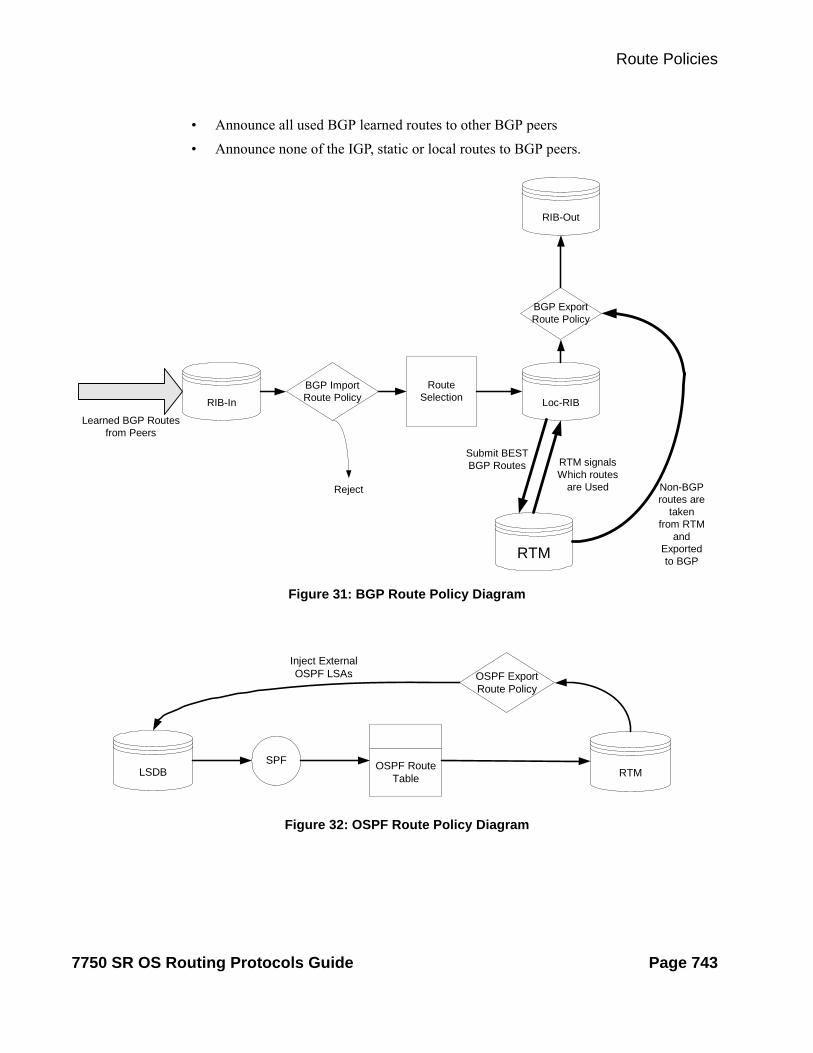
Route Policies
• Announce all used BGP learned routes to other BGP peers
Figure 32: OSPF Route Policy Diagram
Figure 31: BGP Route Policy Diagram
LSDBSPF OSPF Route
Table
OSPF ExportRoute Policy
RTM
Inject ExternalOSPF LSAs
• Announce none of the IGP, static or local routes to BGP peers.
RIB-In
Learned BGP Routesfrom Peers
BGP ImportRoute Policy Loc-RIB
RouteSelection
RTM
Reject
Submit BESTBGP Routes RTM signals
Which routesare Used
RIB-Out
BGP ExportRoute Policy
Non-BGProutes are
takenfrom RTM
andExportedto BGP
7750 SR OS Routing Protocols Guide Page 743

Regular Expressions
Re-advertised Route Policies
Occasionally, BGP routes may be readvertised from BGP into OSPF, IS-IS, and RIP. OSPF export policies (policies control which routes are exported to OSPF) are not handled by the main OSPF task but are handled by a separate task or an RTM task that filters the routes before they are presented to the main OSPF task.
Triggered Policies
With triggered policy enabled, deletion and re-addition of a peer after making changes to export policy causes the new updates sent out to all peers
Triggered policy is not honored if a new peer added to BGP. Update with the old policy is sent to the newly added peer. New policy does not get applied to the new peer until the peer is flapped.
With triggered policy enabled, if a new bgp/static route comes in, new addition or modification of an export policy causes the updates to sent out dynamically to all peers with the new/modified export policy
When multiple peers, say P1, P2 and P3 share the same export policy, any modifications to export policy followed by clear soft on one of the peer P1, will send out routes to P1 only according to newly modified policy.
Though routes with newly modified policy are not sent to other peers (P2, and P3) as no clear soft issues on these peers, RIB-OUT will show that new routes with modified policy are sent to all the peers. RIB-IN on peers P2 and P3 are shown correctly.
Set MED to IGP Cost using Route Policies
This feature sets MED to the IGP cost of a route exported into BGP as an action in route policies. The med-out command in the bgp, group, and neighbor configuration context supports this option, but this method lacks per-prefix granularity. The enhanced metric command supported as a route policy action supports setting MED to a fixed number, or adding, or subtracting a fixed number from the received MED, and sets IGP cost option. The enhanced metric {set {igp | number 1} | { add | subtract} number2 } command is under config>router>policy-options>policy-statement>entry>action.
The metric set igp command, when used in a BGP export policy, have the same effect as the current med-out igp command, except that it applies only to the routes matched by the policy entry.
Page 744 7750 SR OS Routing Protocols Guide

Route Policies
The effect of the metric set igp command depends on the route type and policy type as summarized in Table 22.
Table 22: Metric Set IGP Effect
BGP Policly Type
Matched Route Type Set Metric IGP Effect
Export Non-BGP route (static, OSPF, ISIS, etc.) Add MED attribute. Set value to M.
Export BGP route w/o MED Add MED attribute. Set value to D.
Export BGP route with MED (value A) Overwrite MED attribute with value D.
7750 SR OS Routing Protocols Guide Page 745

Regular Expressions
When to Use Route Policies
The following are examples of circumstances of when to configure and apply unique route policies.
• When you want to control the protocol to allow all routes to be imported into the routing table. This enables the routing table to learn about particular routes to enable packet forwarding and redistributing packets into other routing protocols.
• When you want to control the exporting of a protocol’s learned active routes.
• When you want a routing protocol to announce active routes learned from another routing protocol, which is sometimes called route redistribution.
• When you want unique behaviors to control route characteristics. For example, change the route preference.
• When you want unique behaviors to control route characteristics. For example, change the route preference, AS path, or community values to manipulate the control the route selection.
• When you want to control BGP route flapping (damping).
Page 746 7750 SR OS Routing Protocols Guide

Route Policies
Figure 33: Route Policy Configuration and Implementation Flow
Route Policy Configuration Process Overview
Figure 33 displays the process to provision basic route policy parameters.
ENABLE
START
CONFIGURE AS-PATH EXPRESSIONS
CONFIGURE COMMUNITY LISTS
CONFIGURE DAMPING PARAMETERS
CONFIGURE PREFIX LISTs
CONFIGURE ROUTE POLICY
APPLY ROUTE POLICIES
7750 SR OS Routing Protocols Guide Page 747

Configuration Notes
Configuration Notes
This section describes route policy configuration caveats.
General
• When configuring policy statements, the policy statement name must be unique.
Page 748 7750 SR OS Routing Protocols Guide

Route Policies
Configuring Route Policies with CLI
This section provides information to configure route policies using the command line interface.
Topics in this section include:
• Route Policy Configuration Overview on page 750
When to Create Routing Policies on page 750
Policy Evaluation on page 752
Damping on page 755
• Configuring Route Policy Components on page 758
Creating a Route Policy on page 760
Beginning the Policy Statement on page 759
Configuring an Entry on page 762
Configuring a Community List on page 763
Configuring Damping on page 764
Configuring a Prefix List on page 765
Configuring PIM Join/Register Policies on page 766
• Route Policy Configuration Management Tasks on page 769
7750 SR OS Routing Protocols Guide Page 749

Route Policies
Route Policy Configuration Overview
Route policies allow you to configure routing according to specifically defined policies. You can create policies and entries to allow or deny paths based on various parameters such as destination address, protocol, packet size, and community list.
Policies can be as simple or complex as required. A simple policy can block routes for a specific location or IP address. More complex policies can be configured using numerous policy statement entries containing matching conditions to specify whether to accept or reject the route, control how a series of policies are evaluated, and manipulate the characteristics associated with a route.
When to Create Routing Policies
Route policies are created in the config>router context. There are no default route policies. Each route policy must be explicitly created and applied. Applying route policies can introduce more efficiency as well as more complexity to 7750 SR-Series routers’ capabilities.
A route policy impacts the flow of routing information or packets within and through the router. A routing policy can be specified to prevent a particular customer’s routes to be placed in the route table which causes those routes to not forward traffic to various destinations and the routes are not advertised by the routing protocol to neighbors.
Route policies can be created to control:
• A protocol to export all the active routes learned by that protocol.
• Route characteristics to control which route is selected to act as the active route to reach a destination and advertise the route to neighbors.
• Protocol to import all routes into the routing table. A routing table must learn about particular routes to be able to forward packets and redistribute to other routing protocols.
• Damping.
Before a route policy is applied, analyze the policy’s purpose and be aware of the results (and consequences) when packets match the specified criteria and the associated actions and default actions, if specified, are executed. Membership reports can be filtered based on a specific source address.
Page 750 7750 SR OS Routing Protocols Guide

Route Policies
Default Route Policy Actions
Each routing protocol has default behaviors for the import and export of routing information. Table 23 shows the default behavior for each routing protocol.
Table 23: Default Route Policy Actions
Protocol Import Export
OSPF Not applicable. All OSPF routes are accepted from OSPF neighbors and cannot be controlled via route policies.
• Internal routes: All OSPF routes are automatically advertised to all neighbors.
• External routes: By default all non-OSPF learned routes are not advertised to OSPF neighbors
IS-IS Not applicable. All IS-IS routes are accepted from IS-IS neighbors and can not be controlled via route policies
• Internal routes: All IS-IS routes are automatically advertised to all neighbors.
• External routes: By default all non-IS-IS learned routes are not advertised to IS-IS peers.
RIP By default, all RIP-learned routes are accepted.
• External routes: By default all non-RIP learned routes are not advertised to RIP peers.
BGP By default, all routes from BGP peers are accepted and passed to the BGP route selection process.
• Internal routes: By default all active BGP routes are advertised to BGP peers
• External routes: By default all non-BGP learned routes are not advertised to BGP peers.
7750 SR OS Routing Protocols Guide Page 751

Route Policies
Policy Evaluation
Routing policy statements can consist of as few as one or several entries. The entries specify the matching criteria. A route is compared to the first entry in the policy statement. If it matches, the specified entry action is taken, either accepted or rejected. If the action is to accept or reject the route, that action is taken and the evaluation of the route ends.
If the route does not match the first entry, the route is compared to the next entry (if more than one is configured) in the policy statement. If there is a match with the second entry, the specified action is taken. If the action is to accept or reject the route, that action is taken and the evaluation of the route ends, and so on.
Each route policy statement can have a default-action clause defined. If a default-action is defined for one or more of the configured route policies, then the default actions should be handled in the following ways:
• The process stops when the first complete match is found and executes the action defined in the entry.
• If the packet does not match any of the entries, the system executes the default action specified in the policy statement.
Figure 34 depicts an example of the route policy process.
Route policies can also match a given route policy entry and continue to search for other entries within either the same route policy or the next route policy by specifying the next-entry or next-policy option in the entry’s action command. Policies can be constructed to support multiple states to the evaluation and setting of various route attributes.
Figure 35 depicts the next-policy and next-entry route processes.
Page 752 7750 SR OS Routing Protocols Guide

Route Policies
Figure 34: Route Policy Process Example
ROUTE
POLICY-STATEMENT 274DEFAULT ACTION
ENTRY 1
ENTRY 20
ENTRY 30
ENTRY ACTION:
ACCEPT OR REJECT
ACCEPT OR REJECT
ACCEPT OR REJECT
POLICY-STATEMENT 275DEFAULT ACTION
ENTRY 1
ENTRY 2
ENTRY 3
ENTRY ACTION:
ACCEPT OR REJECT
ACCEPT OR REJECT
ACCEPT OR REJECT
matches
matches
matches
matches
matches
matches
no match
no match
DEFAULT ACTIONSPECIFIED ?
no
yes
PERFORM ACTION SPECIFIEDBY PROTOCOL
PERFORM DEFAULTACTION
See Table 23, Default Route Poli-cy Actions, on page 751
7750 SR OS Routing Protocols Guide Page 753
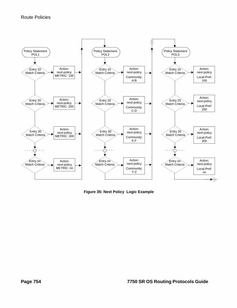
Route Policies
Figure 35: Next Policy Logic Example
Policy StatementPOL1
Entry 10Match Criteria
Entry 20Match Criteria
Entry 30Match Criteria
Entry nnMatch Criteria
Action:
METRIC: 100next-policy
Action:
METRIC: 200next-policy
Action:
METRIC: 300next-policy
Action:
METRIC: nnnext-policy
Policy StatementPOL2
Entry 10Match Criteria
Entry 20Match Criteria
Entry 30Match Criteria
Entry nnMatch Criteria
Action:
Community:
next-policy
Policy StatementPOL3
Entry 10Match Criteria
Entry 20Match Criteria
Entry 30Match Criteria
Entry nnMatch Criteria
A:B
Action:
Community:
next-policy
C:D
Action:
Community:
next-policy
E:F
Action:
Community:
next-policy
Y-Z
Action:
Local-Pref:
next-policy
100
Action:
Local-Pref:
next-policy
200
Action:
Local-Pref:
next-policy
300
Action:
Local-Pref:
next-policy
nn
Page 754 7750 SR OS Routing Protocols Guide

Route Policies
Damping
Damping initiates controls when routes flap. Route flapping can occur when an advertised route between nodes alternates (flaps) back and forth between two paths due to network problems which cause intermittent route failures. It is necessary to reduce the amount of routing state change updates propagated in order to limit processing requirements. Thus, when a route flaps beyond a configured value (the suppress value), then that route is removed from the routing tables and routing protocols until the value falls below the reuse value.
A route can be suppressed according to the Figure of Merit (FoM) value. The FoM is a value that is added to a route each time it flaps. A new route begins with an FoM value of 0.
Damping is optional. If damping is configured, the following parameter values must be explicitly specified as there are no default values:
• suppress
• half-life
• reuse
Figure 36: Damping Example
• max-suppress
When a route's FoM value exceeds the suppress value, then the route is removed from the routing table. The route is considered to be stable when the FoM drops below the reuse value by means of the specified half life parameter. The route is returned to the routing tables. When routes have higher FoM and half life values, they are suppressed for longer periods of time. Figure 36 depicts an example of a flapping route, the suppress threshold, the half life decay (time), and reuse threshold. The peaks represent route flaps, the slopes represent half life decay.
SUPPRESS THRESHOLD
REUSE THRESHOLD
FoM
TIME
7750 SR OS Routing Protocols Guide Page 755
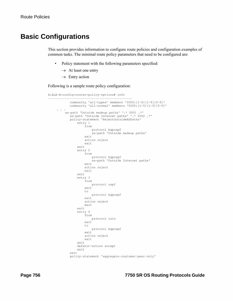
Route Policies
Basic Configurations
This section provides information to configure route policies and configuration examples of common tasks. The minimal route policy parameters that need to be configured are:
• Policy statement with the following parameters specified:
At least one entry
Entry action
Following is a sample route policy configuration:
A:ALA-B>config>router>policy-options# info---------------------------------------------- community "all-types" members "5000:[1-6][1-9][0-9]" community "all-normal" members "5000:[1-5][1-9][0-9]"
. . . as-path "Outside madeup paths" ".* 5001 .*"
as-path "Outside Internet paths" ".* 5002 .*" policy-statement "RejectOutsideASPaths" entry 1 from protocol bgpospf as-path "Outside madeup paths" exit action reject exit exit entry 2 from protocol bgpospf as-path "Outside Internet paths" exit action reject exit exit entry 3 from protocol ospf exit to protocol bgpospf exit action reject exit exit entry 4 from protocol isis exit to protocol bgpospf exit action reject exit exit default-action accept exit exit policy-statement "aggregate-customer-peer-only"
Page 756 7750 SR OS Routing Protocols Guide

Route Policies
entry 1 from community "all-customer-announce" exit action accept exit exit default-action reject exit exit----------------------------------------------A:ALA-B>config>router>policy-options#
7750 SR OS Routing Protocols Guide Page 757

Route Policies
Configuring Route Policy Components
Use the CLI syntax displayed below to configure:
• Creating a Route Policy on page 760
• Beginning the Policy Statement on page 759
• Configuring an Entry on page 762
• Configuring a Community List on page 763
• Configuring Damping on page 764
• Configuring a Prefix List on page 765
• Configuring PIM Join/Register Policies on page 766
Page 758 7750 SR OS Routing Protocols Guide

Route Policies
Beginning the Policy Statement
Use the following CLI syntax to begin a policy statement configuration. In order for a policy statement to be complete an entry must be specified (see Configuring an Entry on page 762).
CLI Syntax: config>router>policy-optionsbegin
policy-statement namedescription text
The following error message displays when the you try to modify a policy options command without entering begin first.
A:ALA-B>config>router>policy-options# policy-statement “allow all”MINOR: CLI The policy-options must be in edit mode by calling begin before any changes can be made.
The following example displays policy statement configuration command usage. These commands are configured in the config>router context.
Example: config>router# policy-optionspolicy-options# begin
There are no default policy statement options. All parameters must be explicitly configured.
7750 SR OS Routing Protocols Guide Page 759

Route Policies
Creating a Route Policy
To enter the mode to create or edit route policies, you must enter the begin keyword at the config>router>policy-options prompt. Other editing commands include:
• The commit command saves changes made to route policies during a session.
• The abort command discards changes that have been made to route policies during a session.
The following error message displays when the you try to modify a policy options command without entering begin first.
A:ALA-B>config>router>policy-options# policy-statement “allow all”MINOR: CLI The policy-options must be in edit mode by calling begin before any changes can be made.
A:ALA-B>config>router>policy-options# info#------------------------------------------# Policy#------------------------------------------
policy-options begin policy-statement "allow all"
description "General Policy"...
exitexit
----------------------------------------------A:ALA-B>config>router>policy-options#
Page 760 7750 SR OS Routing Protocols Guide

Route Policies
Configuring a Default Action
Specifying a default action is optional. The default action controls those packets not matching any policy statement entries. If no default action is specified for the policy, then the action associated with the protocol to which the routing policy was applied is performed. The default action is applied only to those routes that do not match any policy entries.
A policy statement must include at least one entry (see Configuring an Entry on page 762).
To enter the mode to create or edit route policies, you must enter the begin keyword at the config>router>policy-options prompt. Other editing commands include:
• The commit command saves changes made to route policies during a session.
• The abort command discards changes that have been made to route policies during a session.
The following example displays the default action configuration:
A:ALA-B>config>router>policy-options# info---------------------------------------------- policy-statement "1" default-action accept as-path add "test" community add "365" damping "flaptest" next-hop 10.10.10.104 exit exit----------------------------------------------A:ALA-B>config>router>policy-options#
7750 SR OS Routing Protocols Guide Page 761

Route Policies
Configuring an Entry
An entry action must be specified. The other parameters in the entry action context are optional. Refer to the Route Policy Command Reference on page 773 for the commands and syntax.
The following example displays entry parameters and includes the default action parameters which were displayed in the previous section.
A:ALA-B>config>router>policy-options# info---------------------------------------------- policy-statement "1" entry 1 to protocol bgp neighbor 10.10.10.104 exit action accept exit exit entry 2 from protocol ospf 1 exit to protocol ospf neighbor 10.10.0.91 exit action accept exit exit default-action accept . . . exit exit----------------------------------------------A:ALA-B>config>router>policy-options#
policy-statement "exporttmsgrt" entry 1 from protocol vpn-leak exit action accept exit exit entry 2 from protocol tms exit action accept exit exit exit commit exit
exit
Page 762 7750 SR OS Routing Protocols Guide

Route Policies
Configuring a Community List
Community lists are composed of a group of destinations which share a common property. Community lists allow you to administer actions on a configured group instead of having to execute identical commands for each member.
The following example displays a community list configuration:
A:ALA-B>config>router>policy-options# info ----------------------------------------------
community "eastern" members "100:200"community "western" members "100:300"community "northern" members "100:400"community "southern" members "100:500"community "headquarters" members "100:1000"policy-statement "1"
entry 1 to protocol bgp neighbor 10.10.10.104 exit action accept. . . ----------------------------------------------A:ALA-B>config>router>policy-options#
7750 SR OS Routing Protocols Guide Page 763

Route Policies
Configuring Damping
NOTES:
• For each damping profile, all parameters must be configured.
• The suppress value must be greater than the reuse value (see Figure 36 on page 755).
• Damping can be enabled in the config>router>bgp context on the BGP global, group, and neighbor levels. If damping is enabled, but route policy does not specify a damping profile, the default damping profile will be used. This profile is always present and consists of the following parameters:
half-life: 15 minutes
max-suppress: 60 minutes
suppress: 3000
reuse: 750
The following example displays a damping configuration:
*A:cses-A13>config>router>policy-options# info---------------------------------------------- damping "damptest123" half-life 15 max-suppress 60 reuse 750 suppress 1000 exit----------------------------------------------*A:cses-A13>config>router>policy-options#
Page 764 7750 SR OS Routing Protocols Guide
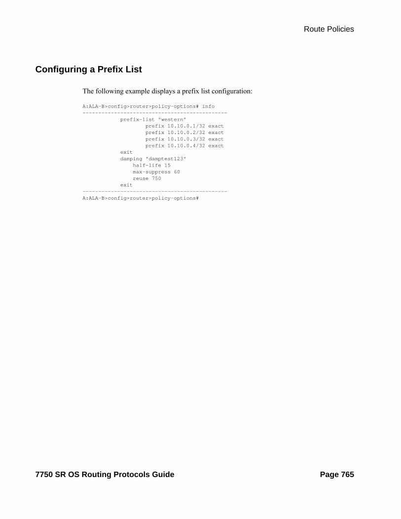
Route Policies
Configuring a Prefix List
The following example displays a prefix list configuration:
A:ALA-B>config>router>policy-options# info---------------------------------------------- prefix-list "western" prefix 10.10.0.1/32 exact prefix 10.10.0.2/32 exact prefix 10.10.0.3/32 exact prefix 10.10.0.4/32 exact exit damping "damptest123" half-life 15 max-suppress 60 reuse 750 exit ----------------------------------------------A:ALA-B>config>router>policy-options#
7750 SR OS Routing Protocols Guide Page 765
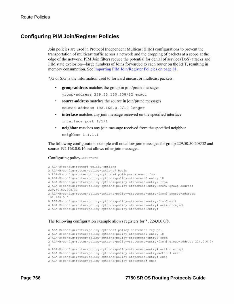
Route Policies
Configuring PIM Join/Register Policies
Join policies are used in Protocol Independent Multicast (PIM) configurations to prevent the transportation of multicast traffic across a network and the dropping of packets at a scope at the edge of the network. PIM Join filters reduce the potential for denial of service (DoS) attacks and PIM state explosion—large numbers of Joins forwarded to each router on the RPT, resulting in memory consumption. See Importing PIM Join/Register Policies on page 81.
*,G or S,G is the information used to forward unicast or multicast packets.
• group-address matches the group in join/prune messages
group-address 229.55.150.208/32 exact
• source-address matches the source in join/prune messages
source-address 192.168.0.0/16 longer
• interface matches any join message received on the specified interface
interface port 1/1/1
• neighbor matches any join message received from the specified neighbor
neighbor 1.1.1.1
The following configuration example will not allow join messages for group 229.50.50.208/32 and source 192.168.0.0/16 but allows other join messages.
Configuring policy-statement
A:ALA-B>config>router# policy-optionsA:ALA-B>config>router>policy-options# beginA:ALA-B>config>router>policy-options# policy-statement fooA:ALA-B>config>router>policy-options>policy-statement$ entry 10A:ALA-B>config>router>policy-options>policy-statement>entry$ fromA:ALA-B>config>router>policy-options>policy-statement>entry>from$ group-address 229.50.50.208/32A:ALA-B>config>router>policy-options>policy-statement>entry>from$ source-address 192.168.0.0A:ALA-B>config>router>policy-options>policy-statement>entry>from$ exitA:ALA-B>config>router>policy-options>policy-statement>entry# action rejectA:ALA-B>config>router>policy-options>policy-statement>entry#
The following configuration example allows registers for *, 224,0.0.0/8.
A:ALA-B>config>router>policy-options# policy-statement reg-polA:ALA-B>config>router>policy-options>policy-statement$ entry 10A:ALA-B>config>router>policy-options>policy-statement>entry$ fromA:ALA-B>config>router>policy-options>policy-statement>entry>from$ group-address 224.0.0.0/8A:ALA-B>config>router>policy-options>policy-statement>entry# action acceptA:ALA-B>config>router>policy-options>policy-statement>entry>action# exitA:ALA-B>config>router>policy-options>policy-statement>entry# exitA:ALA-B>config>router>policy-options>policy-statement# exit
Page 766 7750 SR OS Routing Protocols Guide

Route Policies
A:ALA-B>config>router>policy-options# info----------------------------------------------... policy-statement "foo" entry 10 from group-address "229.50.50.208/32" source-address 192.168.0.0 exit action reject exit exit policy-statement "reg-pol" entry 10 from group-address "224.0.0.0/8" exit action accept exit exit exit...----------------------------------------------A:ALA-B>config>router>policy-options#
7750 SR OS Routing Protocols Guide Page 767
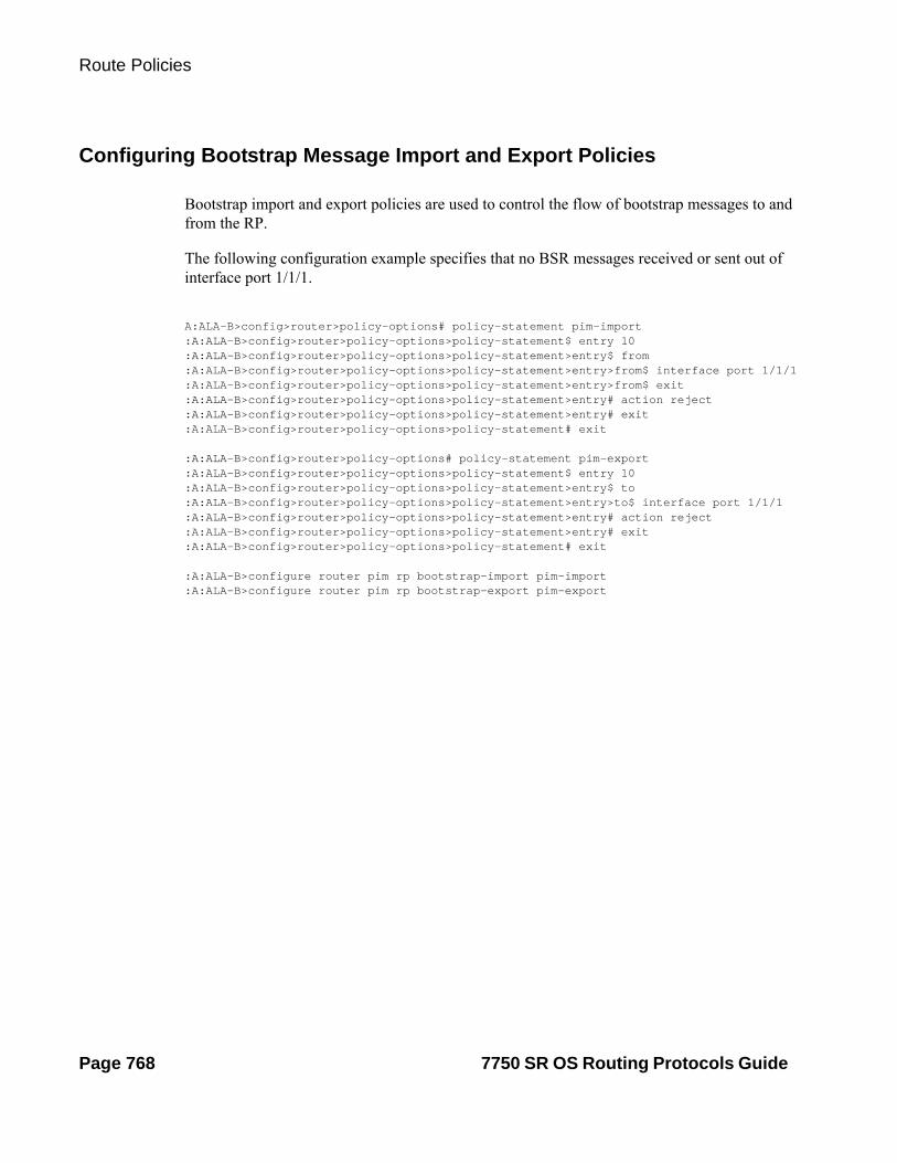
Route Policies
Configuring Bootstrap Message Import and Export Policies
Bootstrap import and export policies are used to control the flow of bootstrap messages to and from the RP.
The following configuration example specifies that no BSR messages received or sent out of interface port 1/1/1.
A:ALA-B>config>router>policy-options# policy-statement pim-import:A:ALA-B>config>router>policy-options>policy-statement$ entry 10:A:ALA-B>config>router>policy-options>policy-statement>entry$ from:A:ALA-B>config>router>policy-options>policy-statement>entry>from$ interface port 1/1/1:A:ALA-B>config>router>policy-options>policy-statement>entry>from$ exit:A:ALA-B>config>router>policy-options>policy-statement>entry# action reject:A:ALA-B>config>router>policy-options>policy-statement>entry# exit:A:ALA-B>config>router>policy-options>policy-statement# exit
:A:ALA-B>config>router>policy-options# policy-statement pim-export:A:ALA-B>config>router>policy-options>policy-statement$ entry 10:A:ALA-B>config>router>policy-options>policy-statement>entry$ to:A:ALA-B>config>router>policy-options>policy-statement>entry>to$ interface port 1/1/1:A:ALA-B>config>router>policy-options>policy-statement>entry# action reject:A:ALA-B>config>router>policy-options>policy-statement>entry# exit:A:ALA-B>config>router>policy-options>policy-statement# exit
:A:ALA-B>configure router pim rp bootstrap-import pim-import:A:ALA-B>configure router pim rp bootstrap-export pim-export
Page 768 7750 SR OS Routing Protocols Guide

Route Policies
Route Policy Configuration Management Tasks
This section discusses the following route policy configuration management tasks:
• Editing Policy Statements and Parameters on page 769
• Deleting an Entry on page 771
• Deleting a Policy Statement on page 771
Editing Policy Statements and Parameters
Route policy statements can be edited to modify, add, or delete parameters. To enter the mode to edit route policies, you must enter the begin keyword at the config>router> policy-options prompt. Other editing commands include:
• The commit command saves changes made to route policies during a session.
• The abort command discards changes that have been made to route policies during a session.
The following example displays a changed configuration:
A:ALA-B>config>router>policy-options>policy-statement# info---------------------------------------------- description "Level 1" entry 1 to protocol bgp neighbor 10.10.10.104 exit action accept exit exit entry 2 from protocol ospf exit to protocol ospf neighbor 10.10.0.91 exit action accept exit exit entry 4 description "new entry" from protocol isis area 0.0.0.20 exit action reject
7750 SR OS Routing Protocols Guide Page 769

Route Policies
exit default-action accept as-path add "test" community add "365" damping "flapper" next-hop 10.10.10.104exit----------------------------------------------
Page 770 7750 SR OS Routing Protocols Guide

Route Policies
Deleting an Entry
Use the following CLI syntax to delete a policy statement entry:
CLI Syntax: config>router>policy-optionsbegincommitabortpolicy-statement name
no entry entry-id
The following example displays the commands required to delete a policy statement entry.
Example: config>router>policy-options# beginpolicy-options# policy-statement "1"policy-options>policy-statement# no entry 4policy-options>policy-statement# commit
Deleting a Policy Statement
Use the following CLI syntax to delete a policy statement:
CLI Syntax: config>router>policy-optionsbegincommitabortno policy-statement name
The following example displays the commands required to delete a policy statement.
Example: config>router>policy-options# beginpolicy-options# no policy-statement 1policy-options# commit
7750 SR OS Routing Protocols Guide Page 771

Route Policies
Page 772 7750 SR OS Routing Protocols Guide

Route Policies
Route Policy Command Reference
Command Hierarchies• Route Policy Configuration Commands on page 773
• Show Commands on page 776
Route Policy Configuration Commands
config — [no] router
— [no] triggered-policy— [no] policy-options
— begin— commit— abort— as-path (policy options) name {regular-expression | null}— no as-path (policy options) name— community name members comm-id [comm-id … (up to 15 max)]— no community name [members comm-id]— [no] damping name
— half-life minutes— no half-life— max-suppress minutes— no max-suppress— reuse integer— no reuse— suppress integer— no suppress
— [no] policy-statement name— default-action {accept | next-entry | next-policy | reject}— no default-action
— as-path {add | replace} name— no as-path— as-path-prepend as-number [ repeat]— no as-path-prepend— community {{add name [remove name]} | {remove name [add
name]} | {replace name}} — no community— damping {name | none} — no damping— local-preference local-preference— no local-preference— metric {add | subtract | set} metric— no metric— next-hop ip-address — no next-hop— [no] next-hop-self
7750 SR OS Routing Protocols Guide Page 773

Route Policy Command Reference
— origin {igp | egp | incomplete}— no origin— preference preference— no preference— tag hex-string— no tag— type {type}— no type
— description description-string— no description— [no] entry entry-id
— action {accept| next-entry | next-policy | reject}— no action
— as-path {add | replace} name— no as-path— as-path-prepend as-number [ repeat]— no as-path-prepend— community {{add name [remove name]} | {remove name
[add name]} | {replace name}} — no community— damping {name | none}— no damping— fc fc [priority {low | high}]— no fc— local-preference local-preference— no local-preference— metric {set {igp | number 1} | { add | subtract} number2}— no metric— next-hop ip-address— no next-hop— [no] next-hop-self— [no] next-hop-self— origin {igp | egp | incomplete}— no origin— preference preference— no preference— tag tag— no tag— type {type}— no type
— description description-string— no description— [no] from
— area area-id— no area— as-path name— no as-path— community name— no community— [no] external— family [ipv4] [ipv6] [mcast-ipv4] [mcast-ipv6] [vpn-
ipv4] [vpn-ipv6] [l2-vpn] [mvpn-ipv4] [mdt-safi] [flow-ipv4] [route-target]
— no family
Page 774 7750 SR OS Routing Protocols Guide

Route Policies
— group-address prefix-list-name— no group-address— host-ip prefix-list-name— no host-ip— interface interface-name— no interface— level {1 | 2}— no level— neighbor {ip-address | prefix-list name}— no neighbor— origin {igp | egp | incomplete | any}— no origin— prefix-list name [name...(up to 5 max)]— no prefix-list— protocol protocol [all | instance instance]— no protocol— source-address ip-address— no source-address— tag tag— no tag— type type— no type
— [no] to— level {1 | 2}— no level— neighbor {ip-address | prefix-list name}— no neighbor— [no] prefix-list name [name...(up to 5 max)]— protocol protocol— no protocol
7750 SR OS Routing Protocols Guide Page 775

Route Policy Command Reference
config — [no] router
— [no] policy-options— [no] prefix-list name
— prefix ip-prefix/prefix-length [exact | longer | through length | prefix-length-range length1-length2]
— no prefix [ipv-prefix/prefix-length] [exact | longer | through length | prefix-length-range length1-length2]
Show Commands
show— router router-name
— policy [name | damping | prefix-list name | as-path name | community name | admin]
Page 776 7750 SR OS Routing Protocols Guide

Route Policies
Route Policy Command Reference
Generic Commands
abort
Syntax abort
Context config>router>policy-options
This command is required to discard changes made to a route policy.
Default none
begin
Syntax begin
Context config>router>policy-options
Description This command is required in order to enter the mode to create or edit route policies.
Default none
commit
Syntax commit
Context config>router>policy-options
Description This command is required to save changes made to a route policy.
Default none
7750 SR OS Routing Protocols Guide Page 777

Generic Commands
description
Syntax description stringno description
Context config>router>policy-options>policy-statementconfig>router>policy-options>policy-statement>entry
Description This command creates a text description which is stored in the configuration file to help identify the content of the entity.
The no form of the command removes the string from the configuration.
Default none
Parameters string — The description character string. Allowed values are any string up to 80 characters long composed of printable, 7-bit ASCII characters. If the string contains special characters (#, $, spaces, etc.), the entire string must be enclosed within double quotes.
Page 778 7750 SR OS Routing Protocols Guide

Route Policies
Route Policy Options
as-path (policy options)
Syntax as-path name {reg-exp | null}no as-path name
Context config>router>policy-options
Description This command creates a route policy AS path regular expression statement to use in route policy entries.
The no form of the command deletes the AS path regular expression statement.
Default No AS path regular expression statement is defined.
Parameters name — The AS path regular expression name. Allowed values are any string up to 32 characters long com-posed of printable, 7-bit ASCII characters. If the string contains special characters (#, $, spaces, etc.), the entire string must be enclosed within double quotes.
reg-exp — The AS path regular expression. Allowed values are any string up to 256 characters long com-posed of printable, 7-bit ASCII characters. If the string contains special characters (#, $, spaces, etc.), the entire string must be enclosed within double quotes.
null — The AS path expressed as an empty regular expression string.
community
Syntax community name members comm-id [comm-id...up to 15 max]no community name [members comm-id ]
Context config>router>policy-options
Description This command creates a route policy community list to use in route policy entries.
The no form of the command deletes the community list or the provided community ID.
Default no community — No community names or members are specified.
Parameters name — The community list name. Allowed values are any string up to 32 characters long composed of printable, 7-bit ASCII characters. If the string contains special characters (#, $, spaces, etc.), the entire string must be enclosed within double quotes.
comm-id — The community ID. Note that up to 15 community ID strings can be specified up to a total max-imum of 72 characters.
Values 72 chars max2byte-asnumber:comm-val | reg-ex | ext-comm | well-known-comm ext-comm type:{ip-address:comm-val | reg-ex1®-ex2 | ip-address®-
ex2 | 2byte-asnumber:ext-comm-val |4byte-asnumber:comm-val}2byte-asnumber 0..65535
7750 SR OS Routing Protocols Guide Page 779

Route Policy Options
comm-val 0..65535reg-ex 72 chars maxtype target, originip-address a.b.c.dext-comm-val 0..42949672954byte-asnumber 0..4294967295reg-ex1 63 chars maxreg-ex2 63 chars maxwell-known-comm null, no-export,no-export-subconfed, no-advertise
A community ID can be specified in different forms:
• as-num:comm.-value — The as-num is the Autonomous System Number (ASN)
Values as-num: 1 — 65535 comm-value: 0 — 65535
• type {target | origin} :as-num:comm.-value – The keywords target or origin denote the community as an extended community of type route target or route origin respectively. The as-num and comm.-value allow the same values as described above for regular community values.
• reg-ex1 reg-ex2— A regular expression string. Allowed values are any string up to 63 characters long composed of printable, 7-bit ASCII characters. If the string contains special characters (#, $, spaces, etc.), the entire string must be enclosed within double quotes.
• well-known-comm — keywords null, no-export, no-export-subconfed, no-advertise
policy-options
Syntax [no] policy-options
Context config>router
Description This command enables the context to configure route policies. Route policies are applied to the routing pro-tocol.
The no form of the command deletes the route policy configuration.
Default none
triggered-policy
Syntax [no] triggered-policy
Context config>router
Description This command triggers route policy re-evaluation.
By default, when a change is made to a policy in the config router policy options context and then committed, the change is effective immediately. There may be circumstances when the changes should or must be delayed; for example, if a policy change is implemented that would effect every BGP peer on a SR-
Page 780 7750 SR OS Routing Protocols Guide

Route Policies
Series router, the consequences could be dramatic. It is more effective to control changes on a peer by peer basis.
If the triggered-policy command is enabled, and a given peer is established, and you want the peer to remain up, then, in order for a change to a route policy to take effect, a clear command with the soft or soft-inbound option must be used. In other words, when a triggered-policy is enabled, any routine policy change or policy assignment change within the protocol will not take effect until the protocol is reset or a clear com-mand is issued to re-evaluate route policies; for example, clear router bgp neighbor x.x.x.x soft. This keeps the peer up and the change made to a route policy is applied only to that peer, or group of peers.
Default Non-dynamic route policy is disabled.
7750 SR OS Routing Protocols Guide Page 781
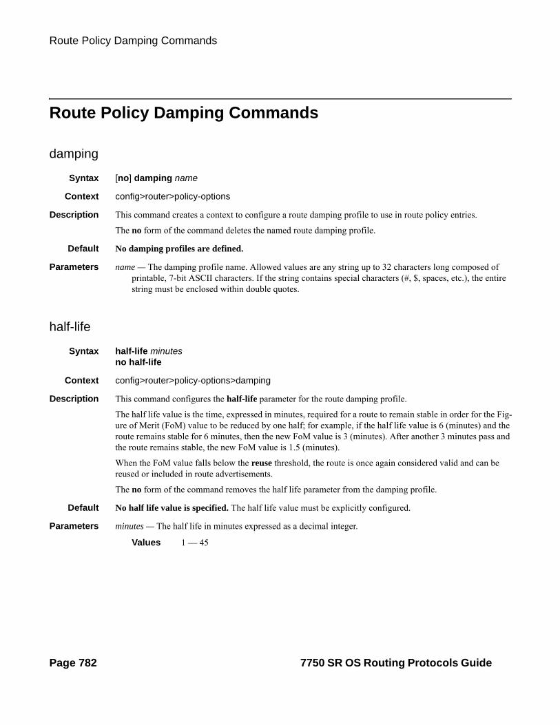
Route Policy Damping Commands
Route Policy Damping Commands
damping
Syntax [no] damping name
Context config>router>policy-options
Description This command creates a context to configure a route damping profile to use in route policy entries.
The no form of the command deletes the named route damping profile.
Default No damping profiles are defined.
Parameters name — The damping profile name. Allowed values are any string up to 32 characters long composed of printable, 7-bit ASCII characters. If the string contains special characters (#, $, spaces, etc.), the entire string must be enclosed within double quotes.
half-life
Syntax half-life minutesno half-life
Context config>router>policy-options>damping
Description This command configures the half-life parameter for the route damping profile.
The half life value is the time, expressed in minutes, required for a route to remain stable in order for the Fig-ure of Merit (FoM) value to be reduced by one half; for example, if the half life value is 6 (minutes) and the route remains stable for 6 minutes, then the new FoM value is 3 (minutes). After another 3 minutes pass and the route remains stable, the new FoM value is 1.5 (minutes).
When the FoM value falls below the reuse threshold, the route is once again considered valid and can be reused or included in route advertisements.
The no form of the command removes the half life parameter from the damping profile.
Default No half life value is specified. The half life value must be explicitly configured.
Parameters minutes — The half life in minutes expressed as a decimal integer.
Values 1 — 45
Page 782 7750 SR OS Routing Protocols Guide

Route Policies
max-suppress
Syntax max-suppress minutesno max-suppress
Context config>router>policy-options>damping
Description This command configures the maximum suppression parameter for the route damping profile.
This value indicates the maximum time, expressed in minutes, that a route can remain suppressed.
The no form of the command removes the maximum suppression parameter from the damping profile.
Default No maximum suppression time is configured.
Parameters minutes — The maximum suppression time, in minutes, expressed as a decimal integer.
Values 1 — 720
reuse
Syntax reuse integerno reuse
Context config>router>policy-options>damping
Description This command configures the reuse parameter for the route damping profile.
When the Figure of Merit (FoM) value falls below the reuse threshold, the route is once again considered valid and can be reused or included in route advertisements.
The no form of the command removes the reuse parameter from the damping profile.
Default No reuse parameter is configured.
Parameters integer — The reuse value expressed as a decimal integer.
Values 1 — 20000
suppress
Syntax suppress integerno suppress
Context config>router>policy-options>damping
Description This command configures the suppression parameter for the route policy damping profile.
A route is suppressed when it has flapped frequently enough to increase the Figure of Merit (FoM) value to exceed the suppress threshold limit. When the FoM value exceeds the suppress threshold limit, the route is removed from the route table or inclusion in advertisements.
The no form of the command removes the suppress parameter from the damping profile.
7750 SR OS Routing Protocols Guide Page 783

Route Policy Damping Commands
Default No suppress parameter is configured.
Parameters integer — The suppress value expressed as a decimal integer.
Values 1 — 20000
Page 784 7750 SR OS Routing Protocols Guide

Route Policies
Route Policy Prefix Commands
prefix-list
Syntax [no] prefix-list name
Context config>router>policy-options
Description This command creates a context to configure a prefix list to use in route policy entries.
The no form of the command deletes the named prefix list.
Default none
Parameters name — The prefix list name. Allowed values are any string up to 32 characters long composed of printable, 7-bit ASCII characters. If the string contains special characters (#, $, spaces, etc.), the entire string must be enclosed within double quotes.
prefix
Syntax [no] prefix ip-prefix/prefix-length { [exact | longer | through length ]| [prefix-length-range length1-length2 ] }no prefix [ipv-prefix/prefix-length] [exact | longer | through length | prefix-length-range length1-length2]
Context config>router>policy-options>prefix-list
Description This command creates a prefix entry in the route policy prefix list.
The no form of the command deletes the prefix entry from the prefix list.
Parameters ip-prefix — The IP prefix for prefix list entry in dotted decimal notation.
Values ipv4-prefix: a.b.c.d (host bits must be 0) ipv4-prefix-length: 0 — 32ipv6-prefix: x:x:x:x:x:x:x:x (eight 16-bit pieces)
x:x:x:x:x:x:d.d.d.dx: [0 — FFFF]Hd: [0 — 255]D
ipv6-prefix-length: 0 — 128
exact — Specifies the prefix list entry only matches the route with the specified ip-prefix and prefix mask (length) values.
longer — Specifies the prefix list entry matches any route that matches the specified ip-prefix and prefix mask length values equal to or greater than the specified mask.
7750 SR OS Routing Protocols Guide Page 785

Route Policy Prefix Commands
through length — Specifies the prefix list entry matches any route that matches the specified ip-prefix and has a prefix length between the specified length values inclusive.
Values 0 — 32
prefix-length-range length1 - length2 — Specifies a route must match the most significant bits and have a prefix length with the given range. The range is inclusive of start and end values.
Values 0 — 32, length2 > length1
Page 786 7750 SR OS Routing Protocols Guide

Route Policies
Route Policy Entry Match Commands
entry
Syntax entry entry-idno entry
Context config>router>policy-options>policy-statement
Description This command creates the context to edit route policy entries within the route policy statement.
Multiple entries can be created using unique entries. The 7750 SR OS exits the filter when the first match is found and executes the action specified. For this reason, entries must be sequenced correctly from most to least explicit.
An entry does not require matching criteria defined (in which case, everything matches) but must have at least define an action in order to be considered complete. Entries without an action are considered incom-plete and will be rendered inactive.
The no form of the command removes the specified entry from the route policy statement.
Default none
Parameters entry-id — The entry ID expressed as a decimal integer. An entry-id uniquely identifies match criteria and the corresponding action. It is recommended that multiple entries be given entry-ids in staggered incre-ments. This allows users to insert a new entry in an existing policy without requiring renumbering of all the existing entries.
Values 1 — 4294967295
area
Syntax area area-idno area
Context config>router>policy-options>policy-statement>entry>from
Description This command configures an OSPF area as a route policy match criterion.
This match criterion is only used in export policies.
All OSPF routes (internal and external) are matched using this criterion if the best path for the route is by the specified area.
The no form of the command removes the OSPF area match criterion.
Default none
Parameters area-id — The OSPF area ID expressed in dotted decimal notation or as a 32-bit decimal integer.
Values 0.0.0.0 — 255.255.255.255 (dotted decimal), 0 — 4294967295 (decimal)
7750 SR OS Routing Protocols Guide Page 787

Route Policy Entry Match Commands
as-path
Syntax as-path nameno as-path
Context config>router>policy-options>policy-statement>entry>from
Description This command configures an AS path regular expression statement as a match criterion for the route policy entry.
If no AS path criterion is specified, any AS path is considered to match.
AS path regular expression statements are configured at the global route policy level (config>router>pol-icy-options>as-path name).
The no form of the command removes the AS path regular expression statement as a match criterion.
Default no as-path — Matches any AS path.
Parameters name — Specifies an existing name. The AS path regular expression name. Allowed values are any string up to 32 characters long composed of printable, 7-bit ASCII characters. If the string contains special characters (#, $, spaces, etc.), the entire string must be enclosed within double quotes.
community
Syntax community nameno community
Context config>router>policy-options>policy-statement>entry>from
Description This command configures a community list as a match criterion for the route policy entry.
If no community list is specified, any community is considered a match.
The no form of the command removes the community list match criterion.
Default no community — Matches any community.
Parameters name — The community list name. Allowed values are any string up to 32 characters long composed of printable, 7-bit ASCII characters. If the string contains special characters (#, $, spaces, etc.), the entire string must be enclosed within double quotes.
The name specified must already be defined.
from
Syntax [no] from
Context config>router>policy-options>policy-statement>entry
Description This command creates the context to configure policy match criteria based on a route’s source or the protocol from which the route is received.
Page 788 7750 SR OS Routing Protocols Guide
Route Policies
If no condition is specified, all route sources are considered to match.
The no form of the command deletes the source match criteria for the route policy statement entry.
external
Syntax [no] external
Context config>router>policy-options>policy-statement>entry>from
Description This command specifies the external route matching criteria for the entry.
Default no external
family
Syntax family [ipv4] [ipv6] [mcast-ipv4] [mcast-ipv6] [vpn-ipv4] [vpn-ipv6] [l2-vpn] [mvpn-ipv4] [mdt-safi] [flow-ipv4] [route-target]no family
Context config>router>policy-options>policy-statement>entry>from
Description This command specifies address families as matching conditions.
Parameters ipv4 — Specifies IPv4 routing information.
ipv6 — Specifies IPv6 routing information.
mcast-ipv4 — Specifies multicast IPv4 routing information.
mcast-ipv6 — Specifies multicast IPv6 routing information.
vpn-ipv4 — Specifies IPv4 VPN routing information.
l2-vpn — Exchanges Layer 2 VPN information.
mvpn-ipv4 — Exchanges Multicast VPN related information
mdt-safi — Exchange Multicast VPN (MDT-SAFI) related information
flow-ipv4 — Exchanges IPv4 flowspec routes belonging to AFI 1 and SAFI 133
route-target — Specifies to use route targets to be advertised to the peers if ORF is enabled for this peer group
7750 SR OS Routing Protocols Guide Page 789

Route Policy Entry Match Commands
group-address
Syntax group-address prefix-list-nameno group-address
Context config>router>policy-options>policy-statement>entry>from
Description This command specifies the multicast group-address prefix list containing multicast group-addresses that are imbedded in the join or prune packet as a filter criterion. The prefix list must be configured prior to entering this command. Prefix lists are configured in the config>router>policy-options>prefix-list context.
The no form of the command removes the criterion from the configuration.
Default no group-address
Parameters prefix-list-name — The prefix-list name. Allowed values are any string up to 32 characters long composed of printable, 7-bit ASCII characters. If the string contains special characters (#, $, spaces, etc.), the entire string must be enclosed within double quotes.
The prefix-list-name is defined in the config>router>policy-options>prefix-list context.
host-ip
Syntax host-ip prefix-list-name
Context config>router>policy-options>policy-statement>entry>from
Description This command specifies a prefix list host IP address as a match criterion for the route policy-statement entry.
Default no host-ip
Parameters prefix-list-name — The prefix-list name. Allowed values are any string up to 32 characters long composed of printable, 7-bit ASCII characters. If the string contains special characters (#, $, spaces, etc.), the entire string must be enclosed within double quotes.
The prefix-list-name is defined in the config>router>policy-options>prefix-list context.
interface
Syntax interface interface-nameno interface
Context config>router>policy-options>policy-statement>entry>from
Description This command specifies the router interface, specified either by name or address, as a filter criterion.
The no form of the command removes the criterion from the configuration.
Default no interface
Parameters ip-int-name — Specify the name of the interface as a match criterion for this entry. If the string contains special characters (#, $, spaces, etc.), the entire string must be enclosed within double quotes.
Page 790 7750 SR OS Routing Protocols Guide

Route Policies
level
Syntax level {1 | 2}no level
Context config>router>policy-options>policy-statement>entry>fromconfig>router>policy-options>policy-statement>entry>to
Description This command specifies the ISIS route level as a match criterion for the entry.
Default no level
Parameters 1 | 2 — Matches the IS-IS route learned from level 1 or level 2.
neighbor
Syntax neighbor {ip-address | prefix-list name}no neighbor
Context config>router>policy-options>policy-statement>entry>toconfig>router>policy-options>policy-statement>entry>from
Description This command specifies the neighbor address as found in the source address of the actual join and prune message as a filter criterion. If no neighbor is specified, any neighbor is considered a match.
The no form of the of the command removes the neighbor IP match criterion from the configuration.
Default no neighbor — Matches any neighbor.
Parameters ip-addr — The neighbor IP address in dotted decimal notation.
Values ipv4-address: a.b.c.d ipv6-address: x:x:x:x:x:x:x:x[-interface]
x:x:x:x:x:x:d.d.d.d[-interface]x: [0 — FFFF]Hd: [0 — 255]Dinterface (32 chars max, mandatory for link local addresses)
prefix-list name — The prefix-list name. Allowed values are any string up to 32 characters long composed of printable, 7-bit ASCII characters. If the string contains special characters (#, $, spaces, etc.), the entire string must be enclosed within double quotes.
The name specified must already be defined.
7750 SR OS Routing Protocols Guide Page 791
Route Policy Entry Match Commands
origin
Syntax origin {igp | egp | incomplete | any | aaa | dhcp | lubd}no origin
Context config>router>policy-options>policy-statement>entry>from
Description This command will configure a match criteria for the origin attribute. Originally, the origin attribute was applicable only to BGP as a mandatory well-known BGP attribute.
The functionality of the origin attribute has expanded to subscriber-management routes (/32 IPv4 host and IPv6 PD wan-host routes). Each subscriber-management route will internally (local to the node) by default carry the origin attribute with one of the three new values (aaa, dhcp and ludb). The value of the attribute will depend on the origin of the subscriber-management route. The aaa, dhcp or ludb values will never be carried in BGP updates as part of the BGP origin attribute or be otherwise visible within the BGP process.
This introduction of the three new values for the origin attribute in the subscriber-management routes will allow customized advertisement of the subscriber-management routes via routing policy.
Default no origin — Matches any BGP origin attribute
Parameters igp — Configures matching path information originating within the local AS.
egp — Configures matching path information originating in another AS.
incomplete — Configures matching path information learned by another method.
any — Specifies to ignore this criteria.
aaa — IPv4
subscriber-management /32 host routes that are originated via Radius framed-ip-address VSA other than 255.255.255.254. The 255.255.255.254 returned by the Radius indicates that the BNG (NAS) should assign an IP address from its own pool.
IPv6
subscriber-management routes that are originated through framed-ipv6-prefix (SLAAC), delegated-ipv6-prefix (IA_PD) or alc-ipv6-address (IA_NA) Radius attributes . This is valid for IPoE and PPPoE type host.
dhcp — IPv4
subscriber-management /32 host routes that are originated via DHCP server (local or remote) and also Radius framed-ip-address=255.255.255.254 (RFC 2865).
IPv6
subscriber-management routes that are assigned via local DHCPv6 server pools whose name is obtained through Alc-Delegated-IPv6-Pool (PD pool) and Framed-IPv6-Pool (NA pool) Radius attributes. This is valid for IPoE and PPPoE type hosts.
In addition, for IPoEv6 only, the pool name can be also obtained via ipv6-delegated-prefix-pool (PD pool) and ipv6-wan-address-pool (NA pool) from LUDB.
ludb — IPv4
Page 792 7750 SR OS Routing Protocols Guide

Route Policies
subscriber-management /32 host routes that are originated via LUDB. This should also cover Radius fallback category (Radius falls back to system-defaults or to LUDB).
IPv6
subscriber-management routes obtained from LUDB via ipv6-address (IA_NA) or ipv6-prefix (IA_PD). This is supported only for IPoE.
policy-statement
Syntax [no] policy-statement name
Context config>router>policy-options
Description This command creates the context to configure a route policy statement.
Route policy statements control the flow of routing information to and from a specific protocol, set of proto-cols, or to a specific BGP neighbor.
The policy-statement is a logical grouping of match and action criteria. A single policy-statement can affect routing in one or more protocols and/or one or more protocols peers/neighbors. A single policy-state-ment can also affect both the import and export of routing information.
The no form of the command deletes the policy statement.
Default no policy-statement — No route policy statements are defined.
Parameters name — The route policy statement name. Allowed values are any string up to 32 characters long composed of printable, 7-bit ASCII characters. If the string contains special characters (#, $, spaces, etc.), the entire string must be enclosed within double quotes.
prefix-list
Syntax prefix-list name [name...up to 5 max]no prefix-list
Context config>router>policy-options>policy-statement>entry>fromconfig>router>policy-options>policy-statement>entry>to
Description This command configures a prefix list as a match criterion for a route policy statement entry.
If no prefix list is specified, any network prefix is considered a match.
The prefix lists specify the network prefix (this includes the prefix and length) a specific policy entry applies.
A maximum of five prefix names can be specified.
The no form of the command removes the prefix list match criterion.
Default no prefix-list — Matches any network prefix.
7750 SR OS Routing Protocols Guide Page 793

Route Policy Entry Match Commands
Parameters name — The prefix list name. Allowed values are any string up to 32 characters long composed of printable, 7-bit ASCII characters. If the string contains special characters (#, $, spaces, etc.), the entire string must be enclosed within double quotes.
protocol
Syntax protocol {protocol} [all | instance instance]no protocol
Context config>router>policy-options>policy-statement>entry>from
Description This command configures a routing protocol as a match criterion for a route policy statement entry. This command is used for both import and export policies depending how it is used.
If no protocol criterion is specified, any protocol is considered a match.
The no form of the command removes the protocol match criterion.
Default no protocol — Matches any protocol.
Parameters protocol — The protocol name to match on.
Values direct, static, bgp, isis, ospf, rip, aggregate, bgp-vpn, igmp, pim, ospf3, ldp, sub-mgmt, mld, managed, vpn-leak, tms, nat
instance — The OSPF or IS-IS instance.
Values 1 — 31
all — OSPF- or ISIS-only keyword.
protocol
Syntax protocol {protocol} [all | instance instance]no protocol
Context config>router>policy-options>policy-statement>entry>to
Description This command configures a routing protocol as a match criterion for a route policy statement entry. This command is used for both import and export policies depending how it is used.
If no protocol criterion is specified, any protocol is considered a match.
The no form of the command removes the protocol match criterion.
Default no protocol — Matches any protocol.
Parameters protocol — The protocol name to match on.
Values direct, static, bgp, isis, ospf, rip, aggregate, bgp-vpn, igmp, pim, ospf3, ldp, sub-mgmt, mld, managed, vpn-leak, nat
Page 794 7750 SR OS Routing Protocols Guide

Route Policies
instance — The OSPF or IS-IS instance.
Values 1 — 31
all — OSPF- or ISIS-only keyword.
source-address
Syntax source-address ip-addressno source-address
Context config>router>policy-options>policy-statement>entry>from
Description This command specifies the source address that is embedded in the join or prune packet as a filter criterion.
The no form of the command removes the criterion from the configuration.
Default none
Description This command specifies a multicast data source address as a match criterion for this entry.
Parameters ip-address — The IP prefix for the IP match criterion in dotted decimal notation.
state
Syntax state [srrp-master | srrp-non-master][no] state
Context config>router>policy-options>policy-statement>entry>from
Description This command will configure a match criteria on the state attribute. The state attribute carries the state of an SRRP instance and it can be applied to:
• subscriber-interface routes
• subscriber-management routes (/32 IPv4 and IPv6 PD wan-host)
• managed-routes (applicable only to IPv4).
Based on the state attribute of the route we can manipulate the route advertisement into the network.
We can enable or disable (in case there is no SRRP running) tracking of SRRP state by routes.
This is done on a per subscriber-interface route basis, where a subscriber-interface route is tracking a single SRRP instance state (SRRP instance might be in a Fate Sharing Group).
For subscriber-management and managed-routes, tracking is enabled per group interface under which SRRP is enabled.
Default none
Description This command specifies a multicast data source address as a match criterion for this entry.
Parameters srrp-master — track routes with the state attribute carrying srrp-master state.
7750 SR OS Routing Protocols Guide Page 795
Route Policy Entry Match Commands
srrp-non-master — track routes with the state attribute carrying srrp-master state
tag
Syntax tag tagno tag
Context config>router>policy-options>policy-statement>entry>from
Description This command adds an integer tag to the static route. These tags are then matched on to control route redis-tribution.
The no form of the command removes the tag field match criterion.
Default no tag — Matches any external LSA tag field.
Parameters tag — Matches a specific external LSA tag field.
Values no-tag, 1 — 4294967295
to
Syntax [no] to
Context config>router>policy-options>policy-statement>entry
Description This command creates the context to configure export policy match criteria based on a route’s destination or the protocol into which the route is being advertised.
If no condition is specified, all route destinations are considered to match.
The to command context only applies to export policies. If it is used for an import policy, match criteria is ignored.
The no form of the command deletes export match criteria for the route policy statement entry.
type
Syntax type {1 | 2}no type
Context config>router>policy-options>policy-statement>entry>from
Description This command configures an OSPF type metric as a match criterion in the route policy statement entry.
If no type is specified, any OSPF type is considered a match.
The no form of the command removes the OSPF type match criterion.
Parameters 1 — Matches OSPF routes with type 1 LSAs.
2 — Matches OSPF routes with type 2 LSAs.
Page 796 7750 SR OS Routing Protocols Guide
Route Policies
Route Policy Action Commands
action
Syntax action {accept | next-entry | next-policy | reject}no action
Context config>router>policy-options>policy-statement>entry
Description This command creates the context to configure actions to take for routes matching a route policy statement entry.
This command is required and must be entered for the entry to be active.
Any route policy entry without the action command will be considered incomplete and will be inactive.
The no form of the command deletes the action context from the entry.
Default no action — No action is defined.
Parameters accept — Specifies routes matching the entry match criteria will be accepted and propagated.
next-entry — Specifies that the actions specified would be made to the route attributes and then policy eval-uation would continue with next policy entry (if any others are specified).
next-policy — Specifies that the actions specified would be made to the route attributesand then policy eval-uation would continue with next route policy (if any others are specified).
reject — Specifies routes matching the entry match criteria would be rejected.
as-path
Syntax as-path {add | replace} nameno as-path
Context config>router>policy-options>policy-statement>default-actionconfig>router>policy-options>policy-statement>entry>action
Description This command assigns a BGP AS path list to routes matching the route policy statement entry.
If no AS path list is specified, the AS path attribute is not changed.
The no form of the command disables the AS path list editing action from the route policy entry.
Default no as-path — The AS path attribute is not changed.
Parameters add — Specifies that the AS path list is to be prepended to an existing AS list.
replace — Specifies AS path list replaces any existing as path attribute.
7750 SR OS Routing Protocols Guide Page 797

Route Policy Action Commands
name — The AS path list name. Allowed values are any string up to 32 characters long composed of print-able, 7-bit ASCII characters. If the string contains special characters (#, $, spaces, etc.), the entire string must be enclosed within double quotes.
The name specified must already be defined.
as-path-prepend
Syntax as-path-prepend as-num [repeat]no as-path-prepend
Context config>router>policy-options>policy-statement>default-actionconfig>router>policy-options>policy-statement>entry>action
Description The command prepends a BGP AS number once or numerous times to the AS path attribute of routes match-ing the route policy statement entry.
If an AS number is not configured, the AS path is not changed.
If the optional number is specified, then the AS number is prepended as many times as indicated by the num-ber.
The no form of the command disables the AS path prepend action from the route policy entry.
Default no as-path-prepend — no AS number prepending configured.
Parameters as-num — The AS number to prepend expressed as a decimal integer.
Values 1 — 4294967295
repeat — The number of times to prepend the specified AS number expressed as a decimal integer.
Values 1 — 50
community
Syntax community {{add name [remove name]} | {remove name [add name]} | {replace name}} no community
Context config>router>policy-options>policy-statement>default-actionconfig>router>policy-options>policy-statement>entry>action
Description This command adds or removes a BGP community list to or from routes matching the route policy statement entry.
If no community list is specified, the community path attribute is not changed.
The community list changes the community path attribute according to the add and remove keywords.
The no form of the command disables the action to edit the community path attribute for the route policy entry.
Default no community — The community path attribute is not changed.
Page 798 7750 SR OS Routing Protocols Guide

Route Policies
Parameters add — The specified community list is added to any existing list of communities.
remove — The specified community list is removed from the existing list of communities.
replace — The specified community list replaces any existing community attribute.
name — The community list name. Allowed values are any string up to 32 characters long composed of printable, 7-bit ASCII characters. If the string contains special characters (#, $, spaces, etc.), the entire string must be enclosed within double quotes.
damping
Syntax damping {name | none}no damping
Context config>router>policy-options>policy-statement >default-actionconfig>router>policy-options>policy-statement>entry>action
Description This command configures a damping profile used for routes matching the route policy statement entry.
If no damping criteria is specified, the default damping profile is used.
The no form of the command removes the damping profile associated with the route policy entry.
Default no damping — Use the default damping profile.
Parameters name — The damping profile name. Allowed values are any string up to 32 characters long composed of printable, 7-bit ASCII characters. If the string contains special characters (#, $, spaces, etc.), the entire string must be enclosed within double quotes.
The name specified must already be defined.
none — Disables route damping for the route policy.
fc
Syntax fc fc [priority {low | high}]no fc
Context config>router>policy-options>policy-statement>entry>action$
Description This command associates a forwarding-class and optionally priority with the routes matched by a route pol-icy entry. The command takes effect when the action of the route policy entry is accept, next-entry or next-policy. It has no effect except in route policies applied as VRF import policies, BGP import policies or RIP import policies.
The no form of the command removes the QoS association of the routes matched by the route policy entry.
Default no fc
7750 SR OS Routing Protocols Guide Page 799

Route Policy Action Commands
Parameters fc — Specify the name of one of the predefined forwarding classes in the system.
Values be, l2, af, l1, h2, ef, h1, nc
Default none (no QoS information is associated with matched routes)
priority {low | high} — This parameter associates an enqueuing priority with routes matched by the policy entry. Specifying a priority is optional.
Values high — Setting the enqueuing parameter to high for a packet increases the likelihood of enqueuing the packet when the ingress queue is congested. Ingress enqueuing priority only affects ingress SAP queuing. Once the packet is placed in a buffer on the ingress queue, the significance of the enqueuing priority is lost.low —Setting the enqueuing parameter to low for a packet decreases the likelihood of enqueuing the packet when the ingress queue is congested. Ingress enqueuing priority only affects ingress SAP queuing, once the packet is placed in a buffer on the ingress queue, the significance of the enqueuing priority is lost.
Default low
default-action
Syntax default-action {accept | next-entry | next-policy | reject}no default-action
Context config>router>policy-options>policy-statement
Description This command enables the context to configure actions for routes that do not match any route policy state-ment entries when the accept parameter is specified.
The default action clause can be set to all available action states including: accept, reject, next-entry and next-policy. If the action states accept or reject then the policy evaluation terminates and the appropriate result is returned.
If a default action is defined and no match(es) occurred with the entries in the policy then the default action clause is used.
If a default action is defined and one or more matches occurred with the entries of the policy then the default action is not used.
The no form of the command deletes the default-action context for the policy statement.
Default no default-action — No default action is specified.
Parameters accept — Specifies routes matching the entry match criteria will be accepted and propagated.
next-entry — Specifies that the actions specified would be made to the route attributes and then policy eval-uation would continue with next policy entry (if any others are specified).
next-policy — Specifies that the actions specified would be made to the route attributes and then policy evaluation would continue with next route policy (if any others are specified).
reject — Specifies routes matching the entry match criteria would be rejected.a
Page 800 7750 SR OS Routing Protocols Guide

Route Policies
local-preference
Syntax local-preference preferenceno local-preference
Context config>router>policy-options>policy-statement>default-actionconfig>router>policy-options>policy-statement>entry
Description This command assigns a BGP local preference to routes matching a route policy statement entry.
If no local preference is specified, the BGP configured local preference is used.
The no form of the command disables assigning a local preference in the route policy entry.
Default No local-preference — BGP default preference is assigned.
Parameters preference — The local preference expressed as a decimal integer.
Values 0 — 4294967295
metric
Syntax metric {set {igp | number 1} | { add | subtract} number2}no metric
Context config>router>policy-options>policy-statement>default-actionconfig>router>policy-options>policy-statement>entry>action
Description In a BGP import or export policy, this command assigns a MED value to routes matched by the policy state-ment entry. The MED value may be set to a fixed value (overriding the received value), set to the routing table cost of the route used to resolve the NEXT_HOP of the BGP route (igp option), or modified by adding or subtracting a fixed value offset.
The no form of the command removes the MED attribute from the matched routes.
Default no metric — Uses the configured metric (if defined) or do not advertise a metric.
Parameters add — Specified integer is added to any existing metric. If the result of the addition results in a number greater than 4294967295, the value 4294967295 is used.
subtract — Specified integer is subtracted from any existing metric. If the result of the subtraction results in a number less than 0, the value of 0 is used.
set — Specified integer replaces any existing metric.
igp — Sets the MED value to the routing table cost of the route used to resolve the NEXT_HOP of the BGP route.
number — The metric modifier expressed as a decimal integer.
Values 0 — 4294967295
7750 SR OS Routing Protocols Guide Page 801

Route Policy Action Commands
next-hop
Syntax next-hop ip-addressno next-hop
Context config>router>policy-options>policy-statement>default-actionconfig>router>policy-options>policy-statement>entry>action
Description This command assigns the specified next hop IP address to routes matching the policy statement entry.
If a next-hop IP address is not specified, the next-hop attribute is not changed.
The no form of the command disables assigning a next hop address in the route policy entry.
Default no next-hop — The next hop attribute is not changed.
Parameters ip-address — The next hop IP address in dotted decimal notation.
Values ipv4-prefix: a.b.c.d (host bits must be 0) ipv4-prefix-length: 0 — 32ipv6-prefix: x:x:x:x:x:x:x:x (eight 16-bit pieces)
x:x:x:x:x:x:d.d.d.dx: [0 — FFFF]Hd: [0 — 255]D
next-hop-self
Syntax [no] next-hop-self
Context config>router>policy-options>policy-statement name>default-actionconfig>router>policy-options>policy-statement>entry>action
Description This command advertises a next hop IP address belonging to this router even if a third-party next hop is available to routes matching the policy statement entry.
The no form of the command disables advertising the next-hop-self option for the route policy entry.
Default no next-hop-self — The next hop IP address is not changed.
next-hop-self
Syntax [no] next-hop-self [multihoming primary-anycast secondary-anycast]
Context config>router>policy-option>policy-statement>entry>action
Description This command configures the group or neighbor to always set the NEXTHOP path attribute to its own physical interface when advertising to a peer. This is primarily used to avoid third-party route advertisements when connected to a multi-access network.
In addition, this command can be used to enable and configure the multi-homing reliency mechanism replacing the usual BGP nexthop with a configured anycast address.
Page 802 7750 SR OS Routing Protocols Guide

Route Policies
The no form of the command returns the setting of the BGP next-hop attribute to the default value determined by the BGP protocol.
Default no next-hop-self
Parameters primary-anycast — Specifies the anycast address that the local node will use to replace the BGP nexthop address in route updates associated peers.
secondary-address — Specifies the anycast address that the local node is to track.
origin
Syntax origin {igp | egp | incomplete}no origin
Context config>router>policy-options>policy-statement name>default-actionconfig>router>policy-options>policy-statement>entry>action
Description This command sets the BGP origin assigned to routes exported into BGP.
If the routes are exported into protocols other than BGP, this option is ignored.
The no form of the command disables setting the BGP origin for the route policy entry.
Default no origin
Parameters igp — Sets the path information as originating within the local AS.
egp — Sets the path information as originating in another AS.
incomplete — Sets the path information as learned by some other means.
preference
Syntax preference preferenceno preference
Context config>router>policy-options>policy-statement name>default-actionconfig>router>policy-options>policy-statement>entry>action>action
Description This command assigns a route preference to routes matching the route policy statement entry.
If no preference is specified, the default Route Table Manager (RTM) preference for the protocol is used.
The no form of the command disables setting an RTM preference in the route policy entry.
Default no preference — No route preference is assigned by the policy entry. The protocol default preference is used.
Parameters preference — The route preference expressed as a decimal integer.
Values 1 — 255 (0 represents unset - MIB only)
7750 SR OS Routing Protocols Guide Page 803
Route Policy Action Commands
tag
Syntax tag tagno tag
Context config>router>policy-options>policy-statement>default-actionconfig>router>policy-options>policy-statement>entry>action
Description This command assigns an OSPF tag to routes matching the entry. The tag value is used to apply a tag to a route for either an OSPF or RIP route. A hexadecimal value of 4 octets can be entered.
For OSPF, all four octets can be used.
For RIP, only the two most significant octets are used if more than two octets are configured.
The no form of the command removes the tag.
Default no tag
Parameters tag — Assigns an OSPF, RIP or ISIS tag to routes matching the entry.
Values Accepts decimal or hex formats: OSPF and ISIS: [0x0..0xFFFFFFFF]HRIP: [0x0..0xFFFF]H
type
Syntax type {type}no type
Context config>router>policy-options>policy-statement name>default-actionconfig>router>policy-options>policy-statement>entry>action
Description This command assigns an OSPF type metric to routes matching the route policy statement entry and being exported into OSPF.
The no form of the command disables assigning an OSPF type in the route policy entry.
Default no type
Parameters type — Specifies the OSPF type metric.
Values 1 — Set as OSPF routes with type 1 LSAs2 — Set as OSPF routes with type 2 LSAs.
Page 804 7750 SR OS Routing Protocols Guide

Route Policies
Show Commands
policy
Syntax policy [name | prefix-list name | admin]
Context show>router
Description This command displays configured policy statement information.
Parameters policy name — Displays information similar to the info command for a specific policy-statement. If a name is provided, the matching policy-statement displays. If no statement name is specified, a list of all policies statements and descriptions display.
prefix-list name — Displays the prefix lists configured in the route policy.
admin — If the keyword admin is included, the entire policy option configuration displays, including any un-committed configuration changes. This command is similar to the info command.
Output Route Policy Output — The following table describes route policy output fields.
Label Description
Policy Displays a list of route policy names.
Description Displays the description of each route policy.
Policies The total number of policies configured.
The following route policy commands are displayed with different command parameter options:
• show router policy on page 805
• show router policy admin on page 806
• show router policy “BGP To RIP” on page 807
• show router policy damping on page 807
Sample Output
The show router policy command displays all configured route policies.show router policy
A:ALA-1# show router policy ===============================================================================Route Policies===============================================================================Policy Description -------------------------------------------------------------------------------Direct And Aggregate Policy Statement ABC-------------------------------------------------------------------------------Policies : ===============================================================================
7750 SR OS Routing Protocols Guide Page 805

Show Commands
A:ALA-1#
The show router policy admin command is similar to the info command which displays information about the route policies and parameters.
show router policy admin
A:ALA-1# show router policy admin prefix-list "All-Routes"
prefix 0.0.0.0/0 longer prefix 2.0.0.0/8 longer prefix 3.0.0.0/8 longer prefix 4.0.0.0/8 longer prefix 5.0.0.0/8 longer prefix 6.0.0.0/8 exact prefix 224.0.0.0/24 longer exit...A:ALA-1#
Page 806 7750 SR OS Routing Protocols Guide

Route Policies
The show router policy name command displays information about a specific route policy.
show router policy “BGP To RIP”description "Policy Statement For 'BGP To RIP'"
description "Policy Statement For 'BGP To RIP'" entry 10 description "Entry For Policy 'BGP To RIP" from protocol bgp exit to protocol rip exit action accept metric set 1 next-hop 10.0.18.200 tag 0x8008135 exit exit default-action rejectA:ALA-1#
show router policy “BGP To RIP”
The show router policy damping command displays information about the route policy damping configu-rations.
show router policy damping
A:ALA-1# show router policy damping
=============================================Route Damping Profiles============================================= damping "TEST-LOW" half-life 22 max-suppress 720 reuse 10000 suppress 15000 exit damping "TEST-HIGH" half-life 22 max-suppress 720 reuse 1000 suppress 5000 exit damping "TEST-MEDIUM" half-life 22 max-suppress 720 reuse 5000 suppress 11000 exit=============================================A:ALA-1#
7750 SR OS Routing Protocols Guide Page 807

Show Commands
Page 808 7750 SR OS Routing Protocols Guide

Standards and Protocol Support
Standards Compliance
IEEE 802.1ab-REV/D3 Station and Media Access Control Connectivity Discovery
IEEE 802.1d BridgingIEEE 802.1p/Q VLAN TaggingIEEE 802.1s Multiple Spanning TreeIEEE 802.1w Rapid Spanning Tree
ProtocolIEEE 802.1x Port Based Network Access
ControlIEEE 802.1ad Provider BridgesIEEE 802.1ah Provider Backbone
BridgesIEEE 802.1ag Service Layer OAMIEEE 802.3ah Ethernet in the First MileIEEE 802.1ak Multiple MAC
Registration ProtocolIEEE 802.3 10BaseTIEEE 802.3ad Link AggregationIEEE 802.3ae 10Gbps EthernetIEEE 802.3ah Ethernet OAMIEEE 802.3u 100BaseTXIEEE 802.3x Flow ControlIEEE 802.3z 1000BaseSX/LXITU-T Y.1731 OAM functions and
mechanisms for Ethernet based networks
ITU-T G.8031 Ethernet linear protection switching
ITU-T G.8032 Ethernet Ring Protection Switching (version 2)
Protocol Support
OSPFRFC 1765 OSPF Database OverflowRFC 2328 OSPF Version 2RFC 2370 Opaque LSA Support RFC 2740 OSPF for IPv6 (OSPFv3)
draft-ietf-ospf-ospfv3-update-14.txtRFC 3101 OSPF NSSA OptionRFC 3137 OSPF Stub Router
Advertisement
RFC 3623 Graceful OSPF Restart – GR helper
RFC 3630 Traffic Engineering (TE) Extensions to OSPF Version 2
RFC 4203 - Shared Risk Link Group (SRLG) sub-TLV
RFC 5185 OSPF Multi-Area AdjacencyRFC 3623 Graceful OSPF Restart — GR
helperRFC 3630 Traffic Engineering (TE)
Extensions to OSPF Version 2RFC 4203 for Shared Risk Link Group
(SRLG) sub-TLV
BGPRFC 1397 BGP Default Route
AdvertisementRFC 1772 Application of BGP in the
InternetRFC 1965 Confederations for BGP RFC 1997 BGP Communities AttributeRFC 2385 Protection of BGP Sessions
via MD5RFC 2439 BGP Route Flap DampeningRFC 2547bis BGP/MPLS VPNsRFC 2918 Route Refresh Capability for
BGP-4RFC 3107 Carrying Label Information in
BGP-4RFC 3392 Capabilities Advertisement
with BGP4RFC 4271 BGP-4 (previously RFC 1771)RFC 4360 BGP Extended Communities
AttributeRFC 4364 BGP/MPLS IP Virtual Private
Networks (VPNs) (previously RFC 2547bis BGP/MPLS VPNs)
RFC 4456 BGP Route Reflection: Alternative to Full-mesh IBGP (previously RFC 1966 & 2796)
RFC 4486 Subcodes for BGP Cease Notification Message
RFC 4577 OSPF as the Provider/Customer Edge Protocol for BGP/MPLS IP Virtual Private Networks (VPNs)
RFC 4659 BGP-MPLS IP Virtual Private Network (VPN) Extension for IPv6 VPN
RFC 4684 Constrained Route Distribution for Border Gateway Protocol/MultiProtocol Label Switching (BGP/MPLS) Internet Protocol (IP) Virtual Private Networks (VPNs)
RFC 4724 Graceful Restart Mechanism for BGP – GR helper
RFC 4760 Multi-protocol Extensions for BGP
RFC 4798 Connecting IPv6 Islands over IPv4 MPLS Using IPv6 Provider Edge Routers (6PE)
RFC 4893 BGP Support for Four-octet AS Number Space
RFC 5004 Avoid BGP Best Path Transitions from One External to Another
RFC 5065 Confederations for BGP (obsoletes 3065)
RFC 5291 Outbound Route Filtering Capability for BGP-4
RFC 5575 Dissemination of Flow Specification Rules
RFC 5668 4-Octet AS Specific BGP Extended Community
draft-ietf-idr-add-pathsdraft-ietf-idr-best-external
IS-ISRFC 1142 OSI IS-IS Intra-domain
Routing Protocol (ISO 10589)RFC 1195 Use of OSI IS-IS for routing in
TCP/IP & dual environmentsRFC 2763 Dynamic Hostname Exchange
for IS-ISRFC 2966 Domain-wide Prefix
Distribution with Two-Level IS-ISRFC 2973 IS-IS Mesh GroupsRFC 3373 Three-Way Handshake for
Intermediate System to Intermediate System (IS-IS) Point-to-Point Adjacencies
Standards and Protocols Page 809

Standards and Protocols
RFC 3567 Intermediate System to Intermediate System (ISIS) Cryptographic Authentication
RFC 3719 Recommendations for Interoperable Networks using IS-IS
RFC 3784 Intermediate System to Intermediate System (IS-IS) Extensions for Traffic Engineering (TE)
RFC 3787 Recommendations for Interoperable IP Networks
RFC 3847 Restart Signaling for IS-IS – GR helper
RFC 4205 for Shared Risk Link Group (SRLG) TLV
draft-ietf-isis-igp-p2p-over-lan-05.txt
IPSecRFC 2401 Security Architecture for the
Internet ProtocolRFC 2409 The Internet Key Exchange
(IKE)RFC 3706 IKE Dead Peer DetectionRFC 3947 Negotiation of NAT-Traversal
in the IKERFC 3948 UDP Encapsulation of IPsec
ESP Packetsdraft-ietf-ipsec-isakmp-xauth-06.txt –
Extended Authentication within ISAKMP/Oakley (XAUTH)
draft-ietf-ipsec-isakmp-modecfg-05.txt – The ISAKMP Configuration Method
IPv6RFC 1981 Path MTU Discovery for IPv6RFC 2375 IPv6 Multicast Address
AssignmentsRFC 2460 Internet Protocol, Version 6
(IPv6) SpecificationRFC 2461 Neighbor Discovery for IPv6RFC 2462 IPv6 Stateless Address Auto
configurationRFC 2463 Internet Control Message
Protocol (ICMPv6) for the Internet Protocol Version 6 Specification
RFC 2464 Transmission of IPv6 Packets over Ethernet Networks
RFC 2529 Transmission of IPv6 over IPv4 Domains without Explicit Tunnels
RFC 2545 Use of BGP-4 Multiprotocol Extension for IPv6 Inter-Domain Routing
RFC 2710 Multicast Listener Discovery (MLD) for IPv6RFC 2740 OSPF for IPv6
RFC 3306 Unicast-Prefix-based IPv6 Multicast Addresses
RFC 3315 Dynamic Host Configuration Protocol for IPv6
RFC 3587 IPv6 Global Unicast Address Format
RFC3590 Source Address Selection for the Multicast Listener Discovery (MLD) Protocol
RFC 3810 Multicast Listener Discovery Version 2 (MLDv2) for IPv6
RFC 4007 IPv6 Scoped Address Architecture
RFC 4193 Unique Local IPv6 Unicast Addresses
RFC 4291 IPv6 Addressing ArchitectureRFC 4552 Authentication/Confidentiality
for OSPFv3RFC 4659 BGP-MPLS IP Virtual Private
Network (VPN) Extension for IPv6 VPN
RFC 5072 IP Version 6 over PPPRFC 5095 Deprecation of Type 0 Routing
Headers in IPv6draft-ietf-isis-ipv6-05draft-ietf-isis-wg-multi-topology-xx.txt
MulticastRFC 1112 Host Extensions for IP
Multicasting (Snooping)RFC 2236 Internet Group Management
Protocol, (Snooping)RFC 3376 Internet Group Management
Protocol, Version 3 (Snooping)RFC 2362 Protocol Independent
Multicast-Sparse Mode (PIMSM)RFC 3618 Multicast Source Discovery
Protocol (MSDP)RFC 3446 Anycast Rendevous Point
(RP) mechanism using Protocol Independent Multicast (PIM) and Multicast Source Discovery Protocol (MSDP)
RFC 4601 Protocol Independent Multicast - Sparse Mode (PIM-SM): Protocol Specification (Revised)
RFC 4604 Using IGMPv3 and MLDv2 for Source-Specific Multicast
RFC 4607 Source-Specific Multicast for IP
RFC 4608 Source-Specific Protocol Independent Multicast in 232/8
RFC 4610 Anycast-RP Using Protocol Independent Multicast (PIM)
RFC 5186, Internet Group Management Protocol Version 3 (IGMPv3)/Multicast Listener Discovery Version 2 (MLDv2) and Multicast Routing Protocol Interaction
draft-ietf-pim-sm-bsr-06.txtdraft-rosen-vpn-mcast-15.txt Multicast in
MPLS/BGP IP VPNsdraft-ietf-mboned-msdp-mib-01.txtdraft-ietf-l3vpn-2547bis-mcast-07:
Multicast in MPLS/BGP IP VPNsdraft-ietf-l3vpn-2547bis-mcast-bgp-05:
BGP Encodings and Procedures for Multicast in MPLS/BGP IP VPNs
RFC 3956: Embedding the Rendezvous Point (RP) Address in an IPv6 Multicast Address
MPLS — GeneralRFC 2430 A Provider Architecture
DiffServ & TERFC 2474 Definition of the DS Field the
IPv4 and IPv6 Headers (Rev)RFC 2597 Assured Forwarding PHB
Group (rev3260)RFC 2598 An Expedited Forwarding
PHBRFC 3031 MPLS ArchitectureRFC 3032 MPLS Label Stack EncodingRFC 3443 Time To Live (TTL)
Processing in Multi-Protocol Label Switching (MPLS) Networks
RFC 4182 Removing a Restriction on the use of MPLS Explicit NULL
RFC 3140 Per-Hop Behavior Identification Codes
RFC 4905, Encapsulation methods for transport of layer 2 frames over MPLS
RFC 5332 MPLS Multicast Encapsulations
MPLS — LDPRFC 3037 LDP Applicability
Page 810 Standards and Protocols

Standards and Protocols
RFC 3478 Graceful Restart Mechanism for LDP – GR helper
RFC 5036 LDP SpecificationRFC 5283 LDP extension for Inter-Area
LSPRFC 5443 LDP IGP Synchronizationdraft-ietf-mpls-ldp-p2mp-05 LDP
Extensions for Point-to-Multipoint and Multipoint-to-Multipoint LSP
draft-ietf-mpls-mldp-in-band-signaling-05 Multipoint LDP in-band signaling for Point-to-Multipoint and Multipoint-to-Multipoint Label Switched Paths
MPLS/RSVP-TERFC 2702 Requirements for Traffic
Engineering over MPLSRFC2747 RSVP Cryptographic
AuthenticationRFC3097 RSVP Cryptographic
Authentication RFC 3209 Extensions to RSVP for
TunnelsRFC 3564 Requirements for Diff-Serv-
aware TERFC 3906 Calculating Interior
Gateway Protocol (IGP) Routes Over Traffic Engineering Tunnels
RFC 4090 Fast reroute Extensions to RSVP-TE for LSP Tunnels
RFC 4124 Protocol Extensions for Support of Diffserv-aware MPLS Traffic Engineering
RFC 4125 Maximum Allocation Bandwidth Constraints Model for Diffserv-aware MPLS Traffic Engineering
RFC 4127 Russian Dolls Bandwidth Constraints Model for Diffserv-aware MPLS Traffic Engineering
RFC 4561 Definition of a RRO Node-Id Sub-Object
RFC 4875 Extensions to Resource Reservation Protocol - Traffic Engineering (RSVP-TE) for Point-to-Multipoint TE Label Switched Paths (LSPs)
RFC 5151 Inter-domain MPLS and GMPLS Traffic Engineering – RSVP-TE Extensions
RFC 5712 MPLS Traffic Engineering Soft Preemption
draft-newton-mpls-te-dynamic-overbooking-00 A Diffserv-TE Implementation Model to dynamically change booking factors during failure events
RFC 5817 Graceful Shutdown in GMPLS Traffic Engineering Networks
MPLS — OAMRFC 4379 Detecting Multi-Protocol
Label Switched (MPLS) Data Plane Failures
draft-ietf-mpls-p2mp-lsp-ping-06 Detecting Data Plane Failures in Point-to-Multipoint Multiprotocol Label Switching (MPLS) - Extensions to LSP Ping
RIPRFC 1058 RIP Version 1RFC 2082 RIP-2 MD5 AuthenticationRFC 2453 RIP Version 2
TCP/IPRFC 768 UDPRFC 1350 The TFTP Protocol (Rev.RFC 791 IPRFC 792 ICMPRFC 793 TCPRFC 826 ARPRFC 854 TelnetRFC 951 BootP (rev)RFC 1519 CIDRRFC 1542 Clarifications and Extensions
for the Bootstrap ProtocolRFC 1812 Requirements for IPv4
RoutersRFC 2347 TFTP option ExtensionRFC 2328 TFTP Blocksize OptionRFC 2349 TFTP Timeout Interval and
Transfer Size optionRFC 2401 Security Architecture for
Internet ProtocolRFC 2428 FTP Extensions for IPv6 and
NATsRFC 3596 DNS Extensions to Support IP
version 6draft-ietf-bfd-mib-00.txtBidirectional
Forwarding Detection Management Information Base
RFC 5880 Bidirectional Forwarding Detection
RFC 5881 BFD IPv4 and IPv6 (Single Hop)
RFC 5883 BFD for Multihop Paths
VRRPRFC 2787 Definitions of Managed
Objects for the Virtual Router Redundancy Protocol
RFC 3768 Virtual Router Redundancy Protocol
RFC 5798, Virtual Router Redundancy Protocol Version 3 for IPv4 and IPv6
PPPRFC 1332 PPP IPCPRFC 1377 PPP OSINLCPRFC 1638/2878PPP BCPRFC 1661 PPP (rev RFC2151)RFC 1662 PPP in HDLC-like FramingRFC 1877 PPP Internet Protocol Control
Protocol Extensions for Name Server Addresses
RFC 1989 PPP Link Quality MonitoringRFC 1990 The PPP Multilink Protocol
(MP)RFC 1994 PPP Challenge Handshake Authentication Protocol (CHAP)RFC 2615 PPP over SONET/SDHRFC 2516 A Method for Transmitting
PPP Over EthernetRFC 2686 The Multi-Class Extension to
Multi-Link PPP
Frame Relay FRF.1.2 - PVC User-to-Network
Interface (UNI) Implementation Agreement
FRF.5 - Frame Relay/ATM PVC Network Interworking Implementation
ANSI T1.617 Annex D, DSS1 — Signalling Specification For Frame Relay Bearer Service.
FRF2.2 -PVC Network-to- Network Interface (NNI) Implementation Agreement.
FRF.12 Frame Relay Fragmentation Implementation Agreement
FRF.16.1 Multilink Frame Relay UNI/NNI Implementation Agreement
ITU-T Q.933 Annex A- Additional procedures for Permanent Virtual Connection (PVC) status management
Standards and Protocols Page 811

Standards and Protocols
ATMRFC 1626 Default IP MTU for use over
ATM AAL5RFC 2514 Definitions of Textual
Conventions and OBJECT_IDENTITIES for ATM Management
RFC 2515 Definition of Managed Objects for ATM Management RFC 2684 Multiprotocol Encapsulation over ATM Adaptation Layer 5
AF-TM-0121.000 Traffic Management Specification Version 4.1
ITU-T Recommendation I.610 - B-ISDN Operation and Maintenance Principles and Functions version 11/95
ITU-T Recommendation I.432.1 – BISDN user-network interface – Physical layer specification: General characteristics
GR-1248-CORE - Generic Requirements for Operations of ATM Network Elements (NEs). Issue 3
GR-1113-CORE - Bellcore, Asynchronous Transfer Mode (ATM) and ATM Adaptation Layer (AAL) Protocols Generic Requirements, Issue 1
AF-ILMI-0065.000 Integrated Local Management Interface (ILMI) Version 4.0
AF-TM-0150.00 Addendum to Traffic Management v4.1 optional minimum desired cell rate indication for UBR
AF-PHY-0086.001, Inverse Multiplexing for ATM (IMA) Specification Version 1.1
DHCPRFC 2131 Dynamic Host Configuration
Protocol (REV)RFC 3046 DHCP Relay Agent
Information Option (Option 82)RFC 1534 Interoperation between DHCP
and BOOTP
VPLSRFC 4762 Virtual Private LAN Services
Using LDP RFC5501: Requirements for Multicast
Support in Virtual Private LAN
Services (previously draft-ietf-l2vpn-vpls-mcast-reqts-04)
draft-ietf-l2vpn-vpls-mcast-reqts-04draft-ietf-l2vpn-signaling-08
PSEUDOWIRERFC 3985 Pseudo Wire Emulation Edge-
to-Edge (PWE3)RFC 4385 Pseudo Wire Emulation Edge-
to-Edge (PWE3) Control Word for Use over an MPLS PSN
RFC 3916 Requirements for Pseudo- Wire Emulation Edge-to-Edge (PWE3)
RFC 4717 Encapsulation Methods for Transport ATM over MPLS Networks (draft-ietf-pwe3-atm-encap-10.txt)
RFC 4816 PWE3 ATM Transparent Cell Transport Service (draft-ietf-pwe3-cell-transport-04.txt)
RFC 4448 Encapsulation Methods for Transport of Ethernet over MPLS Networks (draft-ietf-pwe3-ethernet-encap-11.txt)
RFC 4619 Encapsulation Methods for Transport of Frame Relay over MPLS Networks (draft-ietf-pwe3-frame-relay-07.txt)
RFC 4446 IANA Allocations for PWE3RFC 4447 Pseudowire Setup and
Maintenance Using LDP (draft-ietf-pwe3-control-protocol-17.txt)
RFC 5085, Pseudowire Virtual Circuit Connectivity Verification (VCCV): A Control Channel for Pseudowires
RFC 5659 An Architecture for Multi-Segment Pseudowire Emulation Edge-to-Edge
draft-ietf-l2vpn-vpws-iw-oam-02.txt, OAM Procedures for VPWS Interworking
RFC6310, Pseudowire (PW) OAM Message Mapping
draft-ietf-l2vpn-arp-mediation-19.txt, ARP Mediation for IP Interworking of Layer 2 VPN
RFC6073, Segmented Pseudowire (draft-ietf-pwe3-segmented-pw-18.txt)
draft-ietf-pwe3-dynamic-ms-pw-14.txt, Dynamic Placement of Multi Segment Pseudo Wires
draft-ietf-pwe3-redundancy-bit-06.txt, Pseudowire Preferential Forwarding Status bit definition
draft-ietf-pwe3-redundancy-06.txt, Pseudowire (PW) Redundancy
RFC6391 Flow Aware Transport of Pseudowires over an MPLS PSN
MFA Forum 9.0.0 The Use of Virtual trunks for ATM/MPLS Control Plane Interworking
MFA Forum 12.0.0 Multiservice Interworking - Ethernet over MPLS
MFA forum 13.0.0 - Fault Management for Multiservice Interworking v1.0
MFA Forum 16.0.0 – Multiservice Interworking - IP over MPLS
ANCP/L2CPRFC5851 ANCP framework draft-ietf-ancp-protocol-02.txt ANCP
Protocol
Voice /Video PerformanceITU-T G.107 The E Model- A
computational model for use in planning.
ETSI TS 101 329-5 Annex E extensions- QoS Measurement for VoIP -Method for determining an Equipment Impairment Factor using Passive Monitoring
ITU-T Rec. P.564 - Conformance testing for voice over IP transmission quality assessment models
ITU-T G.1020 - Appendix I - Performance Parameter Definitions for Quality of Speech and other Voiceband Applications Utilizing IP Networks- Mean Absolute Packet Delay Variation.& Markov Models.
RFC 3550 Appendix A.8- RTP: A Transport Protocol for Real-Time Applications- Estimating the Interarrival Jitter
CIRCUIT EMULATIONRFC 4553 Structure-Agnostic Time
Division Multiplexing (TDM) over Packet (SAToP)
RFC 5086 Structure-Aware Time Division Multiplexed (TDM) Circuit Emulation Service over Packet Switched Network (CESoPSN)
Page 812 Standards and Protocols

Standards and Protocols
MEF-8 Implementation Agreement for the Emulation of PDH Circuits over Metro Ethernet Networks, October 2004
RFC 5287 Control Protocol Extensions for the Setup of Time-Division Multiplexing (TDM) Pseudowires in MPLS Networks
SONET/SDHITU-G.841 Telecommunication
Standardization Section of ITU, Types and Characteristics of SDH Networks Protection Architecture, issued in October 1998 and as augmented by Corrigendum1 issued in July 2002
RADIUSRFC 2865 Remote Authentication Dial In
User ServiceRFC 2866 RADIUS Accounting
SSHRFC 4250 The Secure Shell (SSH)
Protocoldraft-ietf-secsh-architecture.txtSSH
Protocol Architecturedraft-ietf-secsh-userauth.txt SSH
Authentication Protocoldraft-ietf-secsh-transport.txt SSH
Transport Layer Protocoldraft-ietf-secsh-connection.txt SSH
Connection Protocoldraft-ietf-secsh- newmodes.txt SSH
Transport Layer Encryption Modes
TACACS+draft-grant-tacacs-02.txt
TimingGR-253-CORE SONET Transport
Systems: Common Generic Criteria. Issue 3, September 2000
ITU-T G.781 Telecommunication Standardization Section of ITU, Synchronization layer functions, issued 09/2008
ITU-T G.813 Telecommunication Standardization Section of ITU, Timing characteristics of SDH equipment slave clocks (SEC), issued 03/2003.
GR-1244-CORE Clocks for the Synchronized Network: Common Generic Criteria, Issue 3, May 2005
ITU-T G.8261 Telecommunication Standardization Section of ITU, Timing and synchronization aspects in packet networks, issued 04/2008.
ITU-T G.8262 Telecommunication Standardization Section of ITU, Timing characteristics of synchronous Ethernet equipment slave clock (EEC), issued 08/2007.
ITU-T G.8264 Telecommunication Standardization Section of ITU, Distribution of timing information through packet networks, issued 10/2008.
NETWORK MANAGEMENTITU-T X.721: Information technology-
OSI-Structure of Management Information
ITU-T X.734: Information technology-OSI-Systems Management: Event Report Management Function
M.3100/3120 Equipment and Connection Models
TMF 509/613 Network Connectivity Model
RFC 1157 SNMPv1RFC 1215 A Convention for Defining
Traps for use with the SNMPRFC 1657 BGP4-MIBRFC 1724 RIPv2-MIBRFC 1850 OSPF-MIBRFC 1907 SNMPv2-MIBRFC 2011 IP-MIBRFC 2012 TCP-MIBRFC 2013 UDP-MIBRFC 2138 RADIUSRFC 2206 RSVP-MIBRFC 2452 IPv6 Management Information
Base for the Transmission Control Protocol
RFC 2454 IPv6 Management Information Base for the User Datagram Protocol
RFC 2465 Management Information Base for IPv6: Textual Conventions and General Group
RFC 2558 SONET-MIBRFC 2571 SNMP-Framework MIBRFC 2572 SNMP-MPD-MIB
RFC 2573 SNMP-Target-&-notification-MIB
RFC 2574 SNMP-User-based-SMMIBRFC 2575 SNMP-View-based ACM-
MIBRFC 2576 SNMP-Community-MIBRFC 2665 EtherLike-MIBRFC 2819 RMON-MIBRFC 2863 IF-MIBRFC 2864 Inverted-stack-MIBRFC 2987 VRRP-MIBRFC 3014 Notification-log MIBRFC 3019 IP Version 6 Management
Information Base for The Multicast Listener Discovery Protocol
RFC 3164 SyslogRFC 3273 HCRMON-MIBRFC 3411 An Architecture for
Describing Simple Network Management Protocol (SNMP) Management Frameworks
RFC 3412 Message Processing and Dispatching for the Simple Network Management Protocol (SNMP)
RFC 3413 Simple Network Management Protocol (SNMP) Applications
RFC 3414 User-based Security Model (USM) for version 3 of the Simple Network Management Protocol (SNMPv3)
RFC 3418 SNMP MIBRFC 4292 IP-Forward-MIBRFC 4293 MIB for the Internet ProtocolRFC 5101 Specification of the IP Flow
Information Export (IPFIX) Protocol for the Exchange of IP Traffic Flow Information
draft-ietf-ospf-mib-update-04.txtdraft-ietf-mpls-lsr-mib-06.txtdraft-ietf-mpls-te-mib-04.txtdraft-ietf-mpls-ldp-mib-07.txtdraft-ietf-isis-wg-mib-05.txtIANA-IFType-MIBIEEE8023-LAG-MIB
Proprietary MIBsTIMETRA-APS-MIB.mibTIMETRA-ATM-MIB.mibTIMETRA-BGP-MIB.mibTIMETRA-BSX-NG-MIB.mibTIMETRA-CAPABILITY-7750-
V4v0.mib
Standards and Protocols Page 813

Standards and Protocols
TIMETRA-CFLOWD-MIB.mibTIMETRA-CHASSIS-MIB.mibTIMETRA-CLEAR-MIB.mibTIMETRA-FILTER-MIB.mibTIMETRA-GLOBAL-MIB.mibTIMETRA-IGMP-MIB.mibTIMETRA-ISIS-MIB.mibTIMETRA-LAG-MIB.mibTIMETRA-LDP-MIB.mibTIMETRA-LOG-MIB.mibTIMETRA-MIRROR-MIB.mibTIMETRA-MPLS-MIB.mibTIMETRA-NG-BGP-MIB.mibTIMETRA-OAM-TEST-MIB.mibTIMETRA-OSPF-NG-MIB.mibTIMETRA-OSPF-V3-MIB.mibTIMETRA-PIM-NG-MIB.mibTIMETRA-PORT-MIB.mibTIMETRA-PPP-MIB.mibTIMETRA-QOS-MIB.mibTIMETRA-RIP-MIB.mibTIMETRA-ROUTE-POLICY-MIB.mibTIMETRA-RSVP-MIB.mibTIMETRA-SECURITY-MIB.mibTIMETRA-SERV-MIB.mibTIMETRA-SUBSCRIBER-
MGMTMIB.mibTIMETRA-SYSTEM-MIB.mibTIMETRA-TC-MIB.mibTIMETRA-VRRP-MIB.mibTIMETRA-VRTR-MIB.mib
Page 814 Standards and Protocols

Index
BBGP
overview 566confederations 577group configuration and peers 568hierarchical levels 569interactions and dependencies 593message types 566route damping 596, 569
configuring 610autonomous system 613basic 610BGP parameters
group 620neighbor 621
command reference 629, 623overview 608route reflection 617, 622, 614management tasks 624
IIP Router
configuringbasic 67service management tasks 87
IS-ISoverview 442
ISO network addressing 446PDU configuration 448routing 443terminology 445
configuringarea address attributes 462basic 465command reference 521enabling IS-IS 468global parameters 471interface level capabilities 463, 476ISO area addresses 470level parameters 468management tasks 481overview 462
router levels 462
MMulticast 21
IGMP 27PIM 30
OOSPF
overview 288AS areas 289
backbone 289NSSA 291stub 290
authentication 303IP subnets 304LSAs 302metrics 302neighbors and adjacencies 301virtual links 300
configuring 317area interface 328, 331basic 317command reference 347designated router 334management tasks 341NSSA 324OSPF area 321overview 316route preferences 338, 336, 318stub area 322virtual link 326
RRIP
overview 234authentication 235hierarchy 239import/export policies 236metrics 236packet format 237
7750 SR OS Routing Protocols Guide Page 815

Index
ripv1 238timers 236version types 235
configuringbasic 245command reference 257interfaces 247management tasks 255overview 244RIP parameters 250
global 252, 253neighbor 254
route policy 248
Route policiesoverview 732
damping 755, 751policy evaluation 752, 733regular expressions 737when to use 746
configuringbeginning 759command reference 773, 763, 760damping 764, 761entry 762management tasks 769overview 750prefix list 765
Page 816 7750 SR OS Routing Protocols Guide