routing products protocols manual - grass...
TRANSCRIPT
Routing Products
Protocols Manual
071020108AUGUST 2010
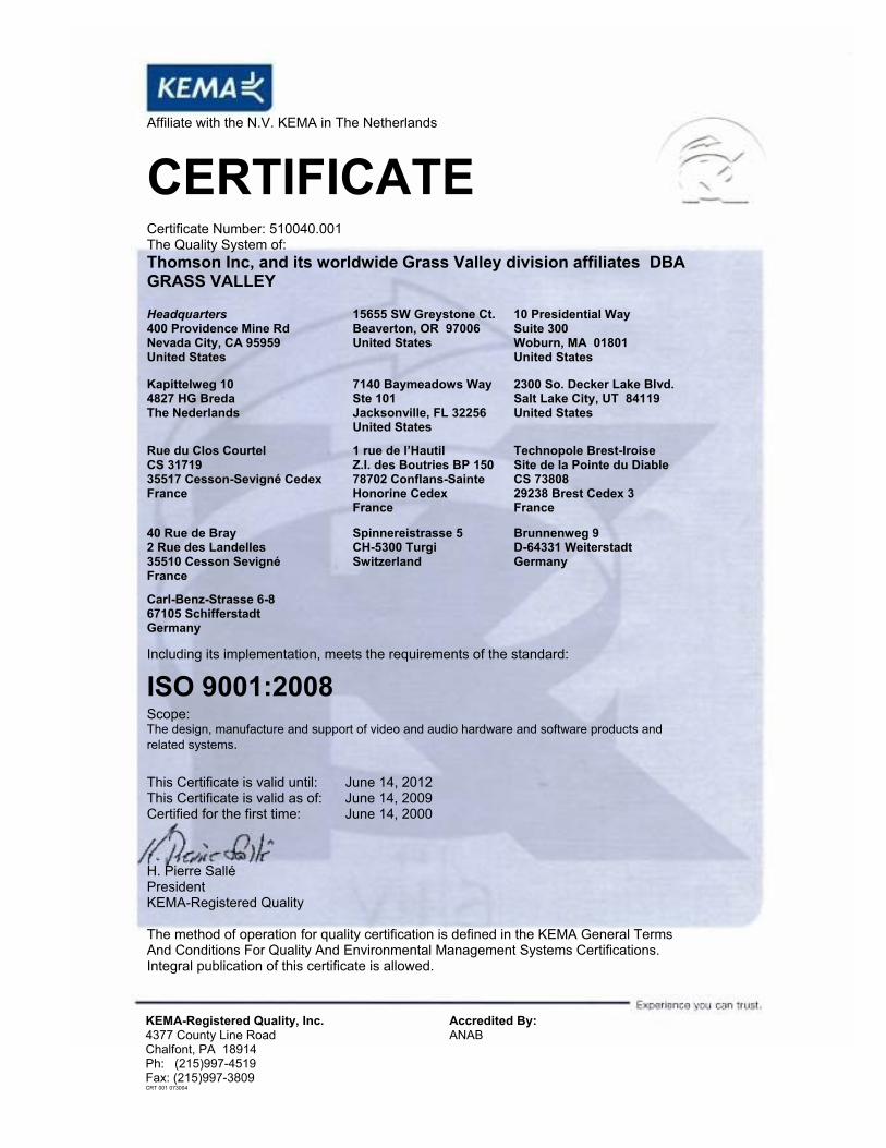
Affiliate with the N.V. KEMA in The Netherlands
CERTIFICATECertificate Number: 510040.001 The Quality System of: Thomson Inc, and its wor dwide Grass Valley division affiliates DBA GRASS VALLEY
Headquarters 400 Providence Mine Rd Nevada City, CA 95959 United States
15655 SW Greystone Ct. Beaverton, OR 97006 United States
10 Presidential Way Suite 300 Woburn, MA 01801 United States
Kapittelweg 10 4827 HG Breda The Nederlands
7140 Baymeadows Way Ste 101 Jacksonville, FL 32256 United States
2300 So. Decker Lake Blvd. Salt Lake City, UT 84119 United States
Rue du Clos Courtel CS 31719 35517 Cesson-Sevigné Cedex France
1 rue de l’Hautil Z.I. des Boutries BP 150 78702 Conflans-Sainte Honorine Cedex France
Technopole Brest-Iroise Site de la Pointe du Diable CS 73808 29238 Brest Cedex 3 France
40 Rue de Bray 2 Rue des Landelles 35510 Cesson Sevigné France
Spinnereistrasse 5 CH-5300 Turgi Switzerland
Brunnenweg 9 D-64331 Weiterstadt Germany
Carl-Benz-Strasse 6-8 67105 Schifferstadt Germany
Including its implementation, meets the requirements of the standard:
ISO 9001:2008 Scope:The design, manufacture and support of video and audio hardware and software products and related systems.
This Certificate is valid until: June 14, 2012 This Certificate is valid as of: June 14, 2009 Certified for the first time: June 14, 2000
H. Pierre Sallé President KEMA-Registered Quality
The method of operation for quality certification is defined in the KEMA General Terms And Conditions For Quality And Environmental Management Systems Certifications. Integral publication of this certificate is allowed.
KEMA-Registered Quality, Inc.4377 County Line Road Chalfont, PA 18914 Ph: (215)997-4519 Fax: (215)997-3809 CRT 001 073004
Accredited By:ANAB
Routing Products
Protocols Manual
071020108AUGUST 2010
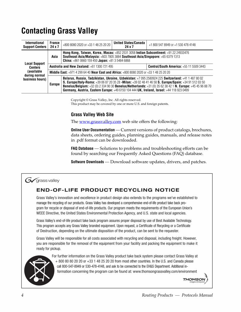
4 Routing Products — Protocols Manual
Contacting Grass ValleyInternational
Support CentersFrance24 x 7 +800 8080 2020 or +33 1 48 25 20 20 United States/Canada
24 x 7 +1 800 547 8949 or +1 530 478 4148
Local Support Centers
(available during normal
business hours)
AsiaHong Kong, Taiwan, Korea, Macau: +852 2531 3058 Indian Subcontinent: +91 22 24933476Southeast Asia/Malaysia: +603 7805 3884 Southeast Asia/Singapore: +65 6379 1313China: +861 0660 159 450 Japan: +81 3 5484 6868
Australia and New Zealand: +61 1300 721 495 Central/South America: +55 11 5509 3443
Middle East: +971 4 299 64 40 Near East and Africa: +800 8080 2020 or +33 1 48 25 20 20
Europe
Belarus, Russia, Tadzikistan, Ukraine, Uzbekistan: +7 095 2580924 225 Switzerland: +41 1 487 80 02S. Europe/Italy-Roma: +39 06 87 20 35 28 -Milan: +39 02 48 41 46 58 S. Europe/Spain: +34 91 512 03 50Benelux/Belgium: +32 (0) 2 334 90 30 Benelux/Netherlands: +31 (0) 35 62 38 42 1 N. Europe: +45 45 96 88 70Germany, Austria, Eastern Europe: +49 6150 104 444 UK, Ireland, Israel: +44 118 923 0499
Copyright © Grass Valley, Inc. All rights reserved.This product may be covered by one or more U.S. and foreign patents.
Grass Valley Web Site The www.grassvalley.com web site offers the following:
Online User Documentation — Current versions of product catalogs, brochures, data sheets, ordering guides, planning guides, manuals, and release notes in .pdf format can be downloaded.
FAQ Database — Solutions to problems and troubleshooting efforts can be found by searching our Frequently Asked Questions (FAQ) database.
Software Downloads — Download software updates, drivers, and patches.
ContentsPreface. . . . . . . . . . . . . . . . . . . . . . . . . . . . . . . . . . . . . . . . . . . . . . . . . . . . . . . . . . . . . . . . . . . . 13
About This Manual . . . . . . . . . . . . . . . . . . . . . . . . . . . . . . . . . . . . . . . . . . . . . . . . . . . . 13
Section 1 — Protocols Overview . . . . . . . . . . . . . . . . . . . . . . . . . . . . . . . . . . . . . . . 15Introduction . . . . . . . . . . . . . . . . . . . . . . . . . . . . . . . . . . . . . . . . . . . . . . . . . . . . . . . . . . 15General Interface Requirements . . . . . . . . . . . . . . . . . . . . . . . . . . . . . . . . . . . . . . . . . 16RCL NP Client Application . . . . . . . . . . . . . . . . . . . . . . . . . . . . . . . . . . . . . . . . . . . . . 16
Section 2 — Grass Valley Router Control Language . . . . . . . . . . . . . . . . . . 17Introduction . . . . . . . . . . . . . . . . . . . . . . . . . . . . . . . . . . . . . . . . . . . . . . . . . . . . . . . . . . 17Command and Message Description Notation . . . . . . . . . . . . . . . . . . . . . . . . . . . . 18Interface Requirements . . . . . . . . . . . . . . . . . . . . . . . . . . . . . . . . . . . . . . . . . . . . . . . . 18
RS-232 or 422 Communication . . . . . . . . . . . . . . . . . . . . . . . . . . . . . . . . . . . . . . . . 18Ethernet Communication . . . . . . . . . . . . . . . . . . . . . . . . . . . . . . . . . . . . . . . . . . . . . 19
Basic RCL Description . . . . . . . . . . . . . . . . . . . . . . . . . . . . . . . . . . . . . . . . . . . . . . . . . 19RS-232 and RS-422 Description . . . . . . . . . . . . . . . . . . . . . . . . . . . . . . . . . . . . . . . . 20
Level 1 . . . . . . . . . . . . . . . . . . . . . . . . . . . . . . . . . . . . . . . . . . . . . . . . . . . . . . . . . . . 20Level 2 . . . . . . . . . . . . . . . . . . . . . . . . . . . . . . . . . . . . . . . . . . . . . . . . . . . . . . . . . . . 20Level 3 . . . . . . . . . . . . . . . . . . . . . . . . . . . . . . . . . . . . . . . . . . . . . . . . . . . . . . . . . . . 21Level 4 . . . . . . . . . . . . . . . . . . . . . . . . . . . . . . . . . . . . . . . . . . . . . . . . . . . . . . . . . . . 21
Ethernet Description . . . . . . . . . . . . . . . . . . . . . . . . . . . . . . . . . . . . . . . . . . . . . . . . . 22Level 1 Description . . . . . . . . . . . . . . . . . . . . . . . . . . . . . . . . . . . . . . . . . . . . . . . . 22Levels 2, 3, and 4 Description. . . . . . . . . . . . . . . . . . . . . . . . . . . . . . . . . . . . . . . . 22
RCL Connection Management . . . . . . . . . . . . . . . . . . . . . . . . . . . . . . . . . . . . . . . . 24RCL Connect. . . . . . . . . . . . . . . . . . . . . . . . . . . . . . . . . . . . . . . . . . . . . . . . . . . . . . 24RCL Disconnect . . . . . . . . . . . . . . . . . . . . . . . . . . . . . . . . . . . . . . . . . . . . . . . . . . . 25RCL Announce . . . . . . . . . . . . . . . . . . . . . . . . . . . . . . . . . . . . . . . . . . . . . . . . . . . . 25
RCL Message Format . . . . . . . . . . . . . . . . . . . . . . . . . . . . . . . . . . . . . . . . . . . . . . . . . . 25Checksum Calculation Algorithm . . . . . . . . . . . . . . . . . . . . . . . . . . . . . . . . . . . . . 27Responses and Errors . . . . . . . . . . . . . . . . . . . . . . . . . . . . . . . . . . . . . . . . . . . . . . . . 27
Level 4 Error . . . . . . . . . . . . . . . . . . . . . . . . . . . . . . . . . . . . . . . . . . . . . . . . . . . . . . 28Message Size and Sequence . . . . . . . . . . . . . . . . . . . . . . . . . . . . . . . . . . . . . . . . . . . 28Level Bitmap. . . . . . . . . . . . . . . . . . . . . . . . . . . . . . . . . . . . . . . . . . . . . . . . . . . . . . . . 29Area Bitmap . . . . . . . . . . . . . . . . . . . . . . . . . . . . . . . . . . . . . . . . . . . . . . . . . . . . . . . . 29
Error Codes . . . . . . . . . . . . . . . . . . . . . . . . . . . . . . . . . . . . . . . . . . . . . . . . . . . . . . . . . . 30Level 2 NAK Errors . . . . . . . . . . . . . . . . . . . . . . . . . . . . . . . . . . . . . . . . . . . . . . . . . . 30
Level 2 (NAK) Error Code Descriptions . . . . . . . . . . . . . . . . . . . . . . . . . . . . . . 30Level 4 Errors . . . . . . . . . . . . . . . . . . . . . . . . . . . . . . . . . . . . . . . . . . . . . . . . . . . . . . . 31
All Level 4 Errors Retrieval . . . . . . . . . . . . . . . . . . . . . . . . . . . . . . . . . . . . . . . . . 31Specific Level 4 Errors Retrieval . . . . . . . . . . . . . . . . . . . . . . . . . . . . . . . . . . . . . 31
RCL Features . . . . . . . . . . . . . . . . . . . . . . . . . . . . . . . . . . . . . . . . . . . . . . . . . . . . . . . . . 32Synchronizing Requests and Responses . . . . . . . . . . . . . . . . . . . . . . . . . . . . . . . . 32Multiple Area Support . . . . . . . . . . . . . . . . . . . . . . . . . . . . . . . . . . . . . . . . . . . . . . . 32
Routing Products — Protocols Manual 5
Contents
Subscription Support . . . . . . . . . . . . . . . . . . . . . . . . . . . . . . . . . . . . . . . . . . . . . . . . 32Exclusion Set Support . . . . . . . . . . . . . . . . . . . . . . . . . . . . . . . . . . . . . . . . . . . . . . . 34Refreshing and Maintaining Protects . . . . . . . . . . . . . . . . . . . . . . . . . . . . . . . . . . 34
RCL Message Categories. . . . . . . . . . . . . . . . . . . . . . . . . . . . . . . . . . . . . . . . . . . . . . . 36Client Originated Messages . . . . . . . . . . . . . . . . . . . . . . . . . . . . . . . . . . . . . . . . . . 36Client Subscription Messages . . . . . . . . . . . . . . . . . . . . . . . . . . . . . . . . . . . . . . . . . 37Server Originated Messages . . . . . . . . . . . . . . . . . . . . . . . . . . . . . . . . . . . . . . . . . . 38
RCL Message Specifications . . . . . . . . . . . . . . . . . . . . . . . . . . . . . . . . . . . . . . . . . . . . 38Client Originated Message Descriptions . . . . . . . . . . . . . . . . . . . . . . . . . . . . . . . . . 39
AS - Assign Source . . . . . . . . . . . . . . . . . . . . . . . . . . . . . . . . . . . . . . . . . . . . . . . . . . 39Command. . . . . . . . . . . . . . . . . . . . . . . . . . . . . . . . . . . . . . . . . . . . . . . . . . . . . . . . 40Response. . . . . . . . . . . . . . . . . . . . . . . . . . . . . . . . . . . . . . . . . . . . . . . . . . . . . . . . . 40
BK - Background Activities . . . . . . . . . . . . . . . . . . . . . . . . . . . . . . . . . . . . . . . . . . . 40CA - Change Alias . . . . . . . . . . . . . . . . . . . . . . . . . . . . . . . . . . . . . . . . . . . . . . . . . . 42CH - Request Chop. . . . . . . . . . . . . . . . . . . . . . . . . . . . . . . . . . . . . . . . . . . . . . . . . . 43CM - Commit Alias Changes . . . . . . . . . . . . . . . . . . . . . . . . . . . . . . . . . . . . . . . . . 44DA - De-Assign Source . . . . . . . . . . . . . . . . . . . . . . . . . . . . . . . . . . . . . . . . . . . . . . 45GA - Get Alias Name . . . . . . . . . . . . . . . . . . . . . . . . . . . . . . . . . . . . . . . . . . . . . . . . 45GT – Get Current VITC Time . . . . . . . . . . . . . . . . . . . . . . . . . . . . . . . . . . . . . . . . . 46PI - Protect by Index . . . . . . . . . . . . . . . . . . . . . . . . . . . . . . . . . . . . . . . . . . . . . . . . . 47PR - Protect . . . . . . . . . . . . . . . . . . . . . . . . . . . . . . . . . . . . . . . . . . . . . . . . . . . . . . . . 47QA- Query Machine Assignment Status . . . . . . . . . . . . . . . . . . . . . . . . . . . . . . . . 48QB - Query Alarm Definitions . . . . . . . . . . . . . . . . . . . . . . . . . . . . . . . . . . . . . . . . 48QC - Query Combined Destination Status . . . . . . . . . . . . . . . . . . . . . . . . . . . . . . 50QD - Query Destination Status . . . . . . . . . . . . . . . . . . . . . . . . . . . . . . . . . . . . . . . . 51QE - Query Error Definition . . . . . . . . . . . . . . . . . . . . . . . . . . . . . . . . . . . . . . . . . . 53QH - Query Alarm Status . . . . . . . . . . . . . . . . . . . . . . . . . . . . . . . . . . . . . . . . . . . . 53QI - Query Destination Status on a Specific Level by Index . . . . . . . . . . . . . . . 55QJ - Query Destination Status by Index . . . . . . . . . . . . . . . . . . . . . . . . . . . . . . . . 55QK - Query Destination Status by Index with Tie Lines Used . . . . . . . . . . . . . 57QM - Query Monitor Status . . . . . . . . . . . . . . . . . . . . . . . . . . . . . . . . . . . . . . . . . . 58Qm- Query Monitors Status with Level Information . . . . . . . . . . . . . . . . . . . . . 59QP - Query Salvo Details along with Protect information . . . . . . . . . . . . . . . . . 59QR - Query Room Details . . . . . . . . . . . . . . . . . . . . . . . . . . . . . . . . . . . . . . . . . . . . 60Qs - Query Salvo Element with Operation Type . . . . . . . . . . . . . . . . . . . . . . . . . 61QT - Query Date & Time . . . . . . . . . . . . . . . . . . . . . . . . . . . . . . . . . . . . . . . . . . . . . 62QU - Query Audio Attributes . . . . . . . . . . . . . . . . . . . . . . . . . . . . . . . . . . . . . . . . . 62QN - Query Names. . . . . . . . . . . . . . . . . . . . . . . . . . . . . . . . . . . . . . . . . . . . . . . . . . 64QV - Query Salvo Elements. . . . . . . . . . . . . . . . . . . . . . . . . . . . . . . . . . . . . . . . . . . 70QX- Query Cached Destination Status by Index . . . . . . . . . . . . . . . . . . . . . . . . . 71QY - Query Cached Destination Status . . . . . . . . . . . . . . . . . . . . . . . . . . . . . . . . . 71RC - RCL Connect. . . . . . . . . . . . . . . . . . . . . . . . . . . . . . . . . . . . . . . . . . . . . . . . . . . 72RD - RCL Disconnect . . . . . . . . . . . . . . . . . . . . . . . . . . . . . . . . . . . . . . . . . . . . . . . . 72SA - Set Audio Attributes . . . . . . . . . . . . . . . . . . . . . . . . . . . . . . . . . . . . . . . . . . . . 73TA – Take (Breakaway) . . . . . . . . . . . . . . . . . . . . . . . . . . . . . . . . . . . . . . . . . . . . . . 75TD - Take (Single Source) . . . . . . . . . . . . . . . . . . . . . . . . . . . . . . . . . . . . . . . . . . . . 76TI - Take by Level Index . . . . . . . . . . . . . . . . . . . . . . . . . . . . . . . . . . . . . . . . . . . . . 77TJ - Take by Level Bitmap . . . . . . . . . . . . . . . . . . . . . . . . . . . . . . . . . . . . . . . . . . . . 77TM - Take Monitor . . . . . . . . . . . . . . . . . . . . . . . . . . . . . . . . . . . . . . . . . . . . . . . . . . 78TS - Take Salvo . . . . . . . . . . . . . . . . . . . . . . . . . . . . . . . . . . . . . . . . . . . . . . . . . . . . . 79UI - Unprotect by Index . . . . . . . . . . . . . . . . . . . . . . . . . . . . . . . . . . . . . . . . . . . . . . 80UP - Request Unprotect . . . . . . . . . . . . . . . . . . . . . . . . . . . . . . . . . . . . . . . . . . . . . . 80
Client Subscription Message Descriptions . . . . . . . . . . . . . . . . . . . . . . . . . . . . . . . . 81SB – Subscribe . . . . . . . . . . . . . . . . . . . . . . . . . . . . . . . . . . . . . . . . . . . . . . . . . . . . . . 81
6 Routing Products — Protocols Manual
Contents
UB – Unsubscribe Request . . . . . . . . . . . . . . . . . . . . . . . . . . . . . . . . . . . . . . . . . . . . 81Server Originated Message Descriptions. . . . . . . . . . . . . . . . . . . . . . . . . . . . . . . . . . 82
NY – Notification. . . . . . . . . . . . . . . . . . . . . . . . . . . . . . . . . . . . . . . . . . . . . . . . . . . . 82RD - RCL Disconnect . . . . . . . . . . . . . . . . . . . . . . . . . . . . . . . . . . . . . . . . . . . . . . . . 83RN - RCL Announce . . . . . . . . . . . . . . . . . . . . . . . . . . . . . . . . . . . . . . . . . . . . . . . . . 83
Subscription Commands Usage . . . . . . . . . . . . . . . . . . . . . . . . . . . . . . . . . . . . . . . . . 83Status Change Subscriptions . . . . . . . . . . . . . . . . . . . . . . . . . . . . . . . . . . . . . . . . . . 84
Subscribe for Status Change. . . . . . . . . . . . . . . . . . . . . . . . . . . . . . . . . . . . . . . . . 84Unsubscribe for Status Change . . . . . . . . . . . . . . . . . . . . . . . . . . . . . . . . . . . . . . 84Illegal Subscribe and Unsubscribe Combinations. . . . . . . . . . . . . . . . . . . . . . . 85Notification for Status Change. . . . . . . . . . . . . . . . . . . . . . . . . . . . . . . . . . . . . . . 85
Destination Status Change By Index . . . . . . . . . . . . . . . . . . . . . . . . . . . . . . . . . . . 85Subscribe for Status Change. . . . . . . . . . . . . . . . . . . . . . . . . . . . . . . . . . . . . . . . . 85Notification for Destination Status Change . . . . . . . . . . . . . . . . . . . . . . . . . . . . 87Unsubscribe for Status Change . . . . . . . . . . . . . . . . . . . . . . . . . . . . . . . . . . . . . . 87
Configuration Change Subscriptions . . . . . . . . . . . . . . . . . . . . . . . . . . . . . . . . . . . 88Subscribe for Configuration Change. . . . . . . . . . . . . . . . . . . . . . . . . . . . . . . . . . 88Unsubscribe for Configuration Change . . . . . . . . . . . . . . . . . . . . . . . . . . . . . . . 89Notification for Configuration Change . . . . . . . . . . . . . . . . . . . . . . . . . . . . . . . 90
Assignment Change Subscription. . . . . . . . . . . . . . . . . . . . . . . . . . . . . . . . . . . . . . 90Subscribe for Assignment Status Change. . . . . . . . . . . . . . . . . . . . . . . . . . . . . . 90Notification for Assignment Change . . . . . . . . . . . . . . . . . . . . . . . . . . . . . . . . . 91Unsubscribe Assignment Status change. . . . . . . . . . . . . . . . . . . . . . . . . . . . . . . 91
Destination Status Change Subscription (by Index w/ Tie-line Info) . . . . . . . . 92Subscribe for Destination Status Change (By Index w/ Tie-line Info). . . . . . 92Notification for Destination Status Change by Index w/ Tie-line Info . . . . . 93Un-Subscribe Destination Status Change by Index w/ Tie-line Info. . . . . . . 93
Monitor Status Change Subscription . . . . . . . . . . . . . . . . . . . . . . . . . . . . . . . . . . . 94Subscribe for Monitor Status Change . . . . . . . . . . . . . . . . . . . . . . . . . . . . . . . . . 94Notification for Monitor Status Change . . . . . . . . . . . . . . . . . . . . . . . . . . . . . . . 95Unsubscribe Monitor Status Change . . . . . . . . . . . . . . . . . . . . . . . . . . . . . . . . . 95
Monitor Status Change with Level Information . . . . . . . . . . . . . . . . . . . . . . . . . . 96Subscription for Monitor status Change with Levels . . . . . . . . . . . . . . . . . . . . 96Notification for Monitor Status Change . . . . . . . . . . . . . . . . . . . . . . . . . . . . . . . 96Unsubscription for Monitor Status Change . . . . . . . . . . . . . . . . . . . . . . . . . . . . 97
Tie-line Configuration Change Subscription. . . . . . . . . . . . . . . . . . . . . . . . . . . . . 97Subscribe for Tie-line Configuration Change . . . . . . . . . . . . . . . . . . . . . . . . . . 97Notification for Tie-Line Configuration Change. . . . . . . . . . . . . . . . . . . . . . . . 97Unsubscribe Tie-Line Configuration Changes . . . . . . . . . . . . . . . . . . . . . . . . . 97
Source Alias Change Subscription . . . . . . . . . . . . . . . . . . . . . . . . . . . . . . . . . . . . . 98Subscribe for Source Alias Change . . . . . . . . . . . . . . . . . . . . . . . . . . . . . . . . . . . 98Notification for Source Alias Change . . . . . . . . . . . . . . . . . . . . . . . . . . . . . . . . . 98Unsubscribe Source Alias Change. . . . . . . . . . . . . . . . . . . . . . . . . . . . . . . . . . . . 99
Destination Alias Change Subscription . . . . . . . . . . . . . . . . . . . . . . . . . . . . . . . . . 99Subscribe for Destination Alias Change . . . . . . . . . . . . . . . . . . . . . . . . . . . . . . . 99Notification for Destination Alias Change. . . . . . . . . . . . . . . . . . . . . . . . . . . . 100Unsubscribe Destination Alias Change . . . . . . . . . . . . . . . . . . . . . . . . . . . . . . 100
Room Configuration Changes Subscription . . . . . . . . . . . . . . . . . . . . . . . . . . . . 101Subscribe for Room Configuration Change . . . . . . . . . . . . . . . . . . . . . . . . . . . 101Notification for Room Configuration Changes . . . . . . . . . . . . . . . . . . . . . . . . 101Unsubscribe Room Configuration Changes . . . . . . . . . . . . . . . . . . . . . . . . . . 101
Room Linkage Changes Subscription. . . . . . . . . . . . . . . . . . . . . . . . . . . . . . . . . . 101Subscribe for Room Linkage Change . . . . . . . . . . . . . . . . . . . . . . . . . . . . . . . . 102Notification for Room Linkage Change . . . . . . . . . . . . . . . . . . . . . . . . . . . . . . 102
Routing Products — Protocols Manual 7
Contents
Unsubscribe Room Linkage Changes . . . . . . . . . . . . . . . . . . . . . . . . . . . . . . . 102Attribute Status Change Subscription by Index. . . . . . . . . . . . . . . . . . . . . . . . . 102
Subscribe for Attribute Status Change. . . . . . . . . . . . . . . . . . . . . . . . . . . . . . . 103Notification for Attribute Change by Index . . . . . . . . . . . . . . . . . . . . . . . . . . 103Unsubscribe for Attribute Status Change . . . . . . . . . . . . . . . . . . . . . . . . . . . . 104
Attribute Status Change Subscription by Name . . . . . . . . . . . . . . . . . . . . . . . . 104Subscribe for Attribute Status Change. . . . . . . . . . . . . . . . . . . . . . . . . . . . . . . 104Notification for Attribute Change by Name . . . . . . . . . . . . . . . . . . . . . . . . . . 105Unsubscribe for Attribute Status Change . . . . . . . . . . . . . . . . . . . . . . . . . . . . 105
Alarm Status Change . . . . . . . . . . . . . . . . . . . . . . . . . . . . . . . . . . . . . . . . . . . . . . . 106Subscribe for Alarm Status Change . . . . . . . . . . . . . . . . . . . . . . . . . . . . . . . . . 106Notification for Alarm Status Change . . . . . . . . . . . . . . . . . . . . . . . . . . . . . . . 107Unsubscribe for Alarm Status Change. . . . . . . . . . . . . . . . . . . . . . . . . . . . . . . 107
Subscription for Events . . . . . . . . . . . . . . . . . . . . . . . . . . . . . . . . . . . . . . . . . . . . . 108Notification for Events . . . . . . . . . . . . . . . . . . . . . . . . . . . . . . . . . . . . . . . . . . . . 108Unsubscribe for Events. . . . . . . . . . . . . . . . . . . . . . . . . . . . . . . . . . . . . . . . . . . . 109
Section 3 — Series 7000 Native Protocol . . . . . . . . . . . . . . . . . . . . . . . . . . . . 111Introduction. . . . . . . . . . . . . . . . . . . . . . . . . . . . . . . . . . . . . . . . . . . . . . . . . . . . . . . . . 111Command and Message Description Notation . . . . . . . . . . . . . . . . . . . . . . . . . . . 111Interface Requirements . . . . . . . . . . . . . . . . . . . . . . . . . . . . . . . . . . . . . . . . . . . . . . . 112
RS-232 or 422 Communication . . . . . . . . . . . . . . . . . . . . . . . . . . . . . . . . . . . . . . . 112Ethernet Communication . . . . . . . . . . . . . . . . . . . . . . . . . . . . . . . . . . . . . . . . . . . 112
Basic Native Protocol Description . . . . . . . . . . . . . . . . . . . . . . . . . . . . . . . . . . . . . . 113RS-232 and RS-422 Description. . . . . . . . . . . . . . . . . . . . . . . . . . . . . . . . . . . . . . . 113
Level 1 . . . . . . . . . . . . . . . . . . . . . . . . . . . . . . . . . . . . . . . . . . . . . . . . . . . . . . . . . 113Level 2 . . . . . . . . . . . . . . . . . . . . . . . . . . . . . . . . . . . . . . . . . . . . . . . . . . . . . . . . . . 114Level 3 . . . . . . . . . . . . . . . . . . . . . . . . . . . . . . . . . . . . . . . . . . . . . . . . . . . . . . . . . . 115Level 4 . . . . . . . . . . . . . . . . . . . . . . . . . . . . . . . . . . . . . . . . . . . . . . . . . . . . . . . . . . 115
Ethernet Description. . . . . . . . . . . . . . . . . . . . . . . . . . . . . . . . . . . . . . . . . . . . . . . . 116Level 1 Description . . . . . . . . . . . . . . . . . . . . . . . . . . . . . . . . . . . . . . . . . . . . . . 116Levels 2, 3, and 4 Description . . . . . . . . . . . . . . . . . . . . . . . . . . . . . . . . . . . . . . 116
Message Formats . . . . . . . . . . . . . . . . . . . . . . . . . . . . . . . . . . . . . . . . . . . . . . . . . . . . 119Request Command Message Format . . . . . . . . . . . . . . . . . . . . . . . . . . . . . . . . . 119Response Command Message Format. . . . . . . . . . . . . . . . . . . . . . . . . . . . . . . . . 120Level 4 Response Message (ACK Level 4) Format . . . . . . . . . . . . . . . . . . . . . . 121Level 4 Error Message Format . . . . . . . . . . . . . . . . . . . . . . . . . . . . . . . . . . . . . . . 122Message Sizes and Sequences . . . . . . . . . . . . . . . . . . . . . . . . . . . . . . . . . . . . . . . . 123Message Buffer Sizes . . . . . . . . . . . . . . . . . . . . . . . . . . . . . . . . . . . . . . . . . . . . . . . 124Checksum Calculation Algorithm . . . . . . . . . . . . . . . . . . . . . . . . . . . . . . . . . . . . 124Naming Conventions (_name) . . . . . . . . . . . . . . . . . . . . . . . . . . . . . . . . . . . . . . . 126Parameter Quantity (nbr_) . . . . . . . . . . . . . . . . . . . . . . . . . . . . . . . . . . . . . . . . . . 126Level Bitmap . . . . . . . . . . . . . . . . . . . . . . . . . . . . . . . . . . . . . . . . . . . . . . . . . . . . . . 126Refreshing Protects . . . . . . . . . . . . . . . . . . . . . . . . . . . . . . . . . . . . . . . . . . . . . . . . . 127
Error Codes . . . . . . . . . . . . . . . . . . . . . . . . . . . . . . . . . . . . . . . . . . . . . . . . . . . . . . . . . 127Level 2 NAK Errors . . . . . . . . . . . . . . . . . . . . . . . . . . . . . . . . . . . . . . . . . . . . . . . . 127
Level 2 (NAK) Error Code Descriptions . . . . . . . . . . . . . . . . . . . . . . . . . . . . . 128Native Protocol Level 4 Errors . . . . . . . . . . . . . . . . . . . . . . . . . . . . . . . . . . . . . . . 128
Level 4 Error Explanation Retrieval Method 1 . . . . . . . . . . . . . . . . . . . . . . . . 129Level 4 Error Explanation Retrieval Method 2 . . . . . . . . . . . . . . . . . . . . . . . . 129Level 4 Error Explanation Retrieval Method 3 . . . . . . . . . . . . . . . . . . . . . . . . 129
MCPU Level 4 Directed Response Error Messages . . . . . . . . . . . . . . . . . . . . . . 129Native Protocol Messages . . . . . . . . . . . . . . . . . . . . . . . . . . . . . . . . . . . . . . . . . . . . . 131
8 Routing Products — Protocols Manual

Contents
Available Two Letter Commands . . . . . . . . . . . . . . . . . . . . . . . . . . . . . . . . . . . . . 131Trailing <HT>. . . . . . . . . . . . . . . . . . . . . . . . . . . . . . . . . . . . . . . . . . . . . . . . . . . . 132Client Subscription Messages . . . . . . . . . . . . . . . . . . . . . . . . . . . . . . . . . . . . . . 132Server Originated Messages. . . . . . . . . . . . . . . . . . . . . . . . . . . . . . . . . . . . . . . . 132
AS - Machine Assign . . . . . . . . . . . . . . . . . . . . . . . . . . . . . . . . . . . . . . . . . . . . . . . . 132BK - Background Activities . . . . . . . . . . . . . . . . . . . . . . . . . . . . . . . . . . . . . . . . . . 133CH - Request Chop . . . . . . . . . . . . . . . . . . . . . . . . . . . . . . . . . . . . . . . . . . . . . . . . . 135CT - Clear Tielines . . . . . . . . . . . . . . . . . . . . . . . . . . . . . . . . . . . . . . . . . . . . . . . . . . 136DA - Machine De-assign. . . . . . . . . . . . . . . . . . . . . . . . . . . . . . . . . . . . . . . . . . . . . 136PI - Protect by Index . . . . . . . . . . . . . . . . . . . . . . . . . . . . . . . . . . . . . . . . . . . . . . . . 136PR - Request Protect . . . . . . . . . . . . . . . . . . . . . . . . . . . . . . . . . . . . . . . . . . . . . . . . 137QA - Query Machine Assignment Status. . . . . . . . . . . . . . . . . . . . . . . . . . . . . . . 137QB - Query Alarm Definitions. . . . . . . . . . . . . . . . . . . . . . . . . . . . . . . . . . . . . . . . 138QC - Query Combined Destination Status. . . . . . . . . . . . . . . . . . . . . . . . . . . . . . 139QD - Query Destination Status . . . . . . . . . . . . . . . . . . . . . . . . . . . . . . . . . . . . . . . 140Qd - Query Destination Status. . . . . . . . . . . . . . . . . . . . . . . . . . . . . . . . . . . . . . . . 141QE - Query Error Definition. . . . . . . . . . . . . . . . . . . . . . . . . . . . . . . . . . . . . . . . . . 142QH - Query Alarm Status. . . . . . . . . . . . . . . . . . . . . . . . . . . . . . . . . . . . . . . . . . . . 142QI - Query Destination Status By Index. . . . . . . . . . . . . . . . . . . . . . . . . . . . . . . . 143Qi - Query Destination Status By Index . . . . . . . . . . . . . . . . . . . . . . . . . . . . . . . . 144QJ - Query Destination Status By Index. . . . . . . . . . . . . . . . . . . . . . . . . . . . . . . . 144Qj - Query Destination Status By Index . . . . . . . . . . . . . . . . . . . . . . . . . . . . . . . . 146QL - Query Destination Status With Tieline Info . . . . . . . . . . . . . . . . . . . . . . . . 146Ql - Query Destination Status With Tieline Info. . . . . . . . . . . . . . . . . . . . . . . . . 147QN - Query Names . . . . . . . . . . . . . . . . . . . . . . . . . . . . . . . . . . . . . . . . . . . . . . . . . 149QT - Query Date & Time . . . . . . . . . . . . . . . . . . . . . . . . . . . . . . . . . . . . . . . . . . . . 152QV - Query Salvo Status. . . . . . . . . . . . . . . . . . . . . . . . . . . . . . . . . . . . . . . . . . . . . 153ST - Request Set Date & Time . . . . . . . . . . . . . . . . . . . . . . . . . . . . . . . . . . . . . . . . 153TA - Request Take . . . . . . . . . . . . . . . . . . . . . . . . . . . . . . . . . . . . . . . . . . . . . . . . . . 153TD - Request Take Destination . . . . . . . . . . . . . . . . . . . . . . . . . . . . . . . . . . . . . . . 154TI - Request Take Index With Level Index . . . . . . . . . . . . . . . . . . . . . . . . . . . . . 154TJ - Request Take Index With Level Bitmap . . . . . . . . . . . . . . . . . . . . . . . . . . . . 155TM - Request Take Monitor Destination . . . . . . . . . . . . . . . . . . . . . . . . . . . . . . . 155TS - Request Take Salvo . . . . . . . . . . . . . . . . . . . . . . . . . . . . . . . . . . . . . . . . . . . . . 156UI - Unprotect by Index . . . . . . . . . . . . . . . . . . . . . . . . . . . . . . . . . . . . . . . . . . . . . 156UP - Request Unprotect . . . . . . . . . . . . . . . . . . . . . . . . . . . . . . . . . . . . . . . . . . . . . 156
Client Subscription Message Descriptions . . . . . . . . . . . . . . . . . . . . . . . . . . . . . . . 157SB - Subscribe . . . . . . . . . . . . . . . . . . . . . . . . . . . . . . . . . . . . . . . . . . . . . . . . . . . . . . 157UB – Unsubscribe Request . . . . . . . . . . . . . . . . . . . . . . . . . . . . . . . . . . . . . . . . . . . 157
Server Originated Message Descriptions. . . . . . . . . . . . . . . . . . . . . . . . . . . . . . . . . 158NY – Notification. . . . . . . . . . . . . . . . . . . . . . . . . . . . . . . . . . . . . . . . . . . . . . . . . . . 158
Notification Format: . . . . . . . . . . . . . . . . . . . . . . . . . . . . . . . . . . . . . . . . . . . . . . 158Subscription/Unsubscription Commands Usage . . . . . . . . . . . . . . . . . . . . . . . . . 158
Alarm Status Change . . . . . . . . . . . . . . . . . . . . . . . . . . . . . . . . . . . . . . . . . . . . . . . 158Subscribe for Alarm Status Change . . . . . . . . . . . . . . . . . . . . . . . . . . . . . . . . . 158Notification for Alarm Status Change . . . . . . . . . . . . . . . . . . . . . . . . . . . . . . . 159Unsubscribe for Alarm Status Change . . . . . . . . . . . . . . . . . . . . . . . . . . . . . . . 159
Destination Status Change By Index . . . . . . . . . . . . . . . . . . . . . . . . . . . . . . . . . . 160Subscribe for Status Change. . . . . . . . . . . . . . . . . . . . . . . . . . . . . . . . . . . . . . . . 160Notification for Destination Status Change . . . . . . . . . . . . . . . . . . . . . . . . . . . 160Unsubscribe for Status Change . . . . . . . . . . . . . . . . . . . . . . . . . . . . . . . . . . . . . 161
Destination Status Change By Name . . . . . . . . . . . . . . . . . . . . . . . . . . . . . . . . . . 162 Subscribe for Status Change . . . . . . . . . . . . . . . . . . . . . . . . . . . . . . . . . . . . . . . 162Notification for Destination Status Change . . . . . . . . . . . . . . . . . . . . . . . . . . 162
Routing Products — Protocols Manual 9

Contents
Unsubscribe for Status Change . . . . . . . . . . . . . . . . . . . . . . . . . . . . . . . . . . . . . 163Subscription for Events . . . . . . . . . . . . . . . . . . . . . . . . . . . . . . . . . . . . . . . . . . . . . 163
Notification for Events . . . . . . . . . . . . . . . . . . . . . . . . . . . . . . . . . . . . . . . . . . . 163Unsubscribe for Events. . . . . . . . . . . . . . . . . . . . . . . . . . . . . . . . . . . . . . . . . . . . 164
Section 4 — Serial Node Controller Protocol . . . . . . . . . . . . . . . . . . . . . . . . 165Introduction. . . . . . . . . . . . . . . . . . . . . . . . . . . . . . . . . . . . . . . . . . . . . . . . . . . . . . . . . 165Physical Layer . . . . . . . . . . . . . . . . . . . . . . . . . . . . . . . . . . . . . . . . . . . . . . . . . . . . . . . 165
RS-485 . . . . . . . . . . . . . . . . . . . . . . . . . . . . . . . . . . . . . . . . . . . . . . . . . . . . . . . . . . . . 165Link layer. . . . . . . . . . . . . . . . . . . . . . . . . . . . . . . . . . . . . . . . . . . . . . . . . . . . . . . . . . . 166
Format Types. . . . . . . . . . . . . . . . . . . . . . . . . . . . . . . . . . . . . . . . . . . . . . . . . . . . . . 166Link Characteristics . . . . . . . . . . . . . . . . . . . . . . . . . . . . . . . . . . . . . . . . . . . . . . . . 166
Packet Pacing . . . . . . . . . . . . . . . . . . . . . . . . . . . . . . . . . . . . . . . . . . . . . . . . . . . . 166Handshaking . . . . . . . . . . . . . . . . . . . . . . . . . . . . . . . . . . . . . . . . . . . . . . . . . . . . 167
The 02 Protocol . . . . . . . . . . . . . . . . . . . . . . . . . . . . . . . . . . . . . . . . . . . . . . . . . . . . 16702 Message Format . . . . . . . . . . . . . . . . . . . . . . . . . . . . . . . . . . . . . . . . . . . . . . . 167Special 02 Protocol Characters . . . . . . . . . . . . . . . . . . . . . . . . . . . . . . . . . . . . . 167
The 02x Protocol . . . . . . . . . . . . . . . . . . . . . . . . . . . . . . . . . . . . . . . . . . . . . . . . . . . 16802x Message Format:. . . . . . . . . . . . . . . . . . . . . . . . . . . . . . . . . . . . . . . . . . . . . . 168Special 02x Characters . . . . . . . . . . . . . . . . . . . . . . . . . . . . . . . . . . . . . . . . . . . . 168
Packet Layer . . . . . . . . . . . . . . . . . . . . . . . . . . . . . . . . . . . . . . . . . . . . . . . . . . . . . . . . 169Link Messages . . . . . . . . . . . . . . . . . . . . . . . . . . . . . . . . . . . . . . . . . . . . . . . . . . . . . 169
MSG_SET_PRIMARY . . . . . . . . . . . . . . . . . . . . . . . . . . . . . . . . . . . . . . . . . . . . . 170MSG_GET_NC_HEALTH . . . . . . . . . . . . . . . . . . . . . . . . . . . . . . . . . . . . . . . . . 171
The Type 02 Command Set . . . . . . . . . . . . . . . . . . . . . . . . . . . . . . . . . . . . . . . . . . 171Interrogate (1) . . . . . . . . . . . . . . . . . . . . . . . . . . . . . . . . . . . . . . . . . . . . . . . . . . . . 172Connect (2) . . . . . . . . . . . . . . . . . . . . . . . . . . . . . . . . . . . . . . . . . . . . . . . . . . . . . . . 172Tally (3) . . . . . . . . . . . . . . . . . . . . . . . . . . . . . . . . . . . . . . . . . . . . . . . . . . . . . . . . . . 173Connected (4) . . . . . . . . . . . . . . . . . . . . . . . . . . . . . . . . . . . . . . . . . . . . . . . . . . . . . 173Connect_On_Go (5) . . . . . . . . . . . . . . . . . . . . . . . . . . . . . . . . . . . . . . . . . . . . . . . . 174Go (6) . . . . . . . . . . . . . . . . . . . . . . . . . . . . . . . . . . . . . . . . . . . . . . . . . . . . . . . . . . . 174Connect_On_Go_Acknowledge (12) . . . . . . . . . . . . . . . . . . . . . . . . . . . . . . . . . 175Go_Done (13) . . . . . . . . . . . . . . . . . . . . . . . . . . . . . . . . . . . . . . . . . . . . . . . . . . . . . 175
Section 5 — Terminal/Computer Interface Protocol . . . . . . . . . . . . . . . . . 177Introduction. . . . . . . . . . . . . . . . . . . . . . . . . . . . . . . . . . . . . . . . . . . . . . . . . . . . . . . . . 177
Description. . . . . . . . . . . . . . . . . . . . . . . . . . . . . . . . . . . . . . . . . . . . . . . . . . . . . . . . 178Limitations . . . . . . . . . . . . . . . . . . . . . . . . . . . . . . . . . . . . . . . . . . . . . . . . . . . . . . . . 180
T/CI Command Descriptions. . . . . . . . . . . . . . . . . . . . . . . . . . . . . . . . . . . . . . . . . . 180TIN . . . . . . . . . . . . . . . . . . . . . . . . . . . . . . . . . . . . . . . . . . . . . . . . . . . . . . . . . . . . . . 180DIN . . . . . . . . . . . . . . . . . . . . . . . . . . . . . . . . . . . . . . . . . . . . . . . . . . . . . . . . . . . . . . 181DPO. . . . . . . . . . . . . . . . . . . . . . . . . . . . . . . . . . . . . . . . . . . . . . . . . . . . . . . . . . . . . . 184SPO . . . . . . . . . . . . . . . . . . . . . . . . . . . . . . . . . . . . . . . . . . . . . . . . . . . . . . . . . . . . . . 186CPO. . . . . . . . . . . . . . . . . . . . . . . . . . . . . . . . . . . . . . . . . . . . . . . . . . . . . . . . . . . . . . 187
T/CI Error Messages . . . . . . . . . . . . . . . . . . . . . . . . . . . . . . . . . . . . . . . . . . . . . . . . . 188!E01 - Unrecognized Command . . . . . . . . . . . . . . . . . . . . . . . . . . . . . . . . . . . . . . 188!E02 - Output Number too big or Invalid Format . . . . . . . . . . . . . . . . . . . . . . . 188!E04 - Level Number too big or Invalid Format . . . . . . . . . . . . . . . . . . . . . . . . . 189!E07 - Input Number too big or Invalid Format . . . . . . . . . . . . . . . . . . . . . . . . . 189!E12 - Output Number Required . . . . . . . . . . . . . . . . . . . . . . . . . . . . . . . . . . . . . 189!E13 - Input Number Required . . . . . . . . . . . . . . . . . . . . . . . . . . . . . . . . . . . . . . . 189!E75 - Output Protected from Change to a Different Input . . . . . . . . . . . . . . . 189
10 Routing Products — Protocols Manual

Contents
Appendix A — Reference Materials . . . . . . . . . . . . . . . . . . . . . . . . . . . . . . . . . . . 191CheckSum Calculation Code Snippet . . . . . . . . . . . . . . . . . . . . . . . . . . . . . . . . . . . 191ASCII Characters . . . . . . . . . . . . . . . . . . . . . . . . . . . . . . . . . . . . . . . . . . . . . . . . . . . . . 193
Appendix B — Level 4 Error Codes . . . . . . . . . . . . . . . . . . . . . . . . . . . . . . . . . . . . 195Router Control Language Error Codes . . . . . . . . . . . . . . . . . . . . . . . . . . . . . . . . . . 195Native Protocol Error Codes . . . . . . . . . . . . . . . . . . . . . . . . . . . . . . . . . . . . . . . . . . . 198
Index . . . . . . . . . . . . . . . . . . . . . . . . . . . . . . . . . . . . . . . . . . . . . . . . . . . . . . . . . . . . . . . . . . . . . 199
Routing Products — Protocols Manual 11

Contents
12 Routing Products — Protocols Manual

Preface
About This ManualThis document describes external protocols for Grass Valley Routing prod-ucts. It assumes basic familiarity with routing equipment. For information on Grass Valley Routers refer to product manuals.
Routing Products — Protocols Manual 13

Preface
14 Routing Products — Protocols Manual

Section 1Protocols Overview
IntroductionThe Grass Valley Router System can be controlled by external devices, and can also control external devices. Several methods are employed to accom-plish this control. This manual covers the following protocols that allow external control of part or all of a Grass Valley Router System:
• Grass Valley Router Control Language on page 17 (Encore Control System Protocol via RS-232, RS-422, SLIP, or Ethernet),
• Series 7000 Native Protocol on page 111 (Series 7000 Signal Management System Protocol via RS-232, RS-422, SLIP, or Ethernet), and
• Serial Node Controller Protocol on page 165 (Pro-Bel Protocol via RS-485).
Omnibus automation system control of a System 7000, using a variation of the Pro-Bel protocol.
Other control mechanisms listed below that involve protocols are described elsewhere:
• Encore Diagnostic (via VT-100 terminal or emulator),
For reporting diagnostic information, and for issuing simple com-mands for diagnostics and service purposes. This interface is described in the Encore Installation and Service Manual.
• System Diagnostic Interface (Series 70000 via VT-100 terminal or emu-lator),
For reporting diagnostic information, and for issuing simple com-mands for diagnostics, service, and installation purposes. This interface is described in the Series 7000 Installation Manual.
• Pro-Bel System 3 Interface, and
System 7000 Control of a Pro-Bel System 3. This interface is described in the Series 7000 Installation Manual.
• Networked Series 7000 systems.
Uses Native Protocol. Issues relating to networked control are described in the Series 7000 Configuration Manual.
Routing Products — Protocols Manual 15
Section 1 — Protocols Overview
General Interface RequirementsFor successful control, all devices involved must be physically connected with the proper interface, have any required options installed, and be prop-erly configured for the desired connection and protocol.
Requirements differ for different control mechanisms, and are described where appropriate.
Refer to the manufacturer’s documentation of any external device being interfaced to a Grass Valley Router System for information on installation and configuration procedure for these systems
RCL NP Client ApplicationThe RCL (Router Control Language) NP (Native Protocol) Client Applica-tion is a software application implementing the RCL/NP Protocol, it also doubles over as a test tool that talks to any Server implementing the RCL/NP protocol for the various operations that needs to be performed, such as; Takes, Queries, etc. It also provides the capability to interface and control routers, which implement either NP or RCL protocol. Contact Customer Service for more information about this application.
16 Routing Products — Protocols Manual

Section 2Grass Valley Router Control Language
IntroductionThe Grass Valley Router System can be controlled by an external, serial or ethernet connected communicating device such as a personal computer or an automation system. The Router Control Language (RCL) described is intended to facilitate control of the Grass Valley Router.
Commands and error responses are terse and character efficient to maxi-mize throughput. All message bytes are from the ASCII character set (print-able and control characters). This provides the ability to easily log information through the duplex control ports.
Message sizes can be tuned to match receive buffer sizes to maximize throughput.
RCL is implemented in Grass Valley Encore routing systems from Encore Software Version 1.6.5 onwards. SMS7000 and earlier Encore systems do not support RCL.
RCL protocol offers significant advantages over its predecessor Native pro-tocol. The following features facilitate the client to control the routing system in a better way:
• Synchronizing Requests and Responses on page 32,
• Multiple Area Support on page 32,
• Subscription Support on page 32,
• Exclusion Set Support on page 34, and
• Refreshing and Maintaining Protects on page 34.
Routing Products — Protocols Manual 17

Section 2 — Grass Valley Router Control Language
Command and Message Description NotationFor the command parameter descriptions in this section, lower case param-eters must be replaced by user specified information, while upper case parameters must be literally supplied.
Upper case parameters fall into two categories: printable ASCII characters, where they are supplied as shown, and ASCII control characters, where the text shown translates into a hex equivalent.
Notation symbols used in the format descriptions in this section are shown in Table 1.
Table 1. Notation symbols
Symbol Meaning
... A continued sequence.
| Or
[] Optional parameters
< > Choices, or ASCII control characters, or for clarity.
, Comma designates horizontal tab <HT>, the data separator.
For the sake of readability, spaces may be shown in the descriptions where none exist in the protocol definition.
Interface RequirementsIn order to control a Grass Valley Router system using RCL, both the Grass Valley Router and the external device must have RCL protocol implemen-tation.
Communication with the Grass Valley Routing system can be achieved using either a RS-232, a RS-422, or an Ethernet interface.
RS-232 or 422 CommunicationPinouts and cable diagrams for creating RS-232 or 422 connections are available as part of the Installation instructions in Grass Valley product manuals.
Default communication settings are:
• 9600 Baud
• 8 Data Bits
• 1 Stop Bit
• No Parity
18 Routing Products — Protocols Manual
Basic RCL Description
The external device controlling the Routing System must be equipped with an RS-232 or RS-422 Serial Port capable of supporting at least one of the fol-lowing communication rates; 300 k, 600 k, 1.2 k, 2.4 k, 9.6 k, 19.2 k, 38.4 k, or 115.2 k Baud.
Ethernet CommunicationUse of Ethernet is recommended. The network should be closed, for use only by the Grass Valley Router system. Configurations that are connected to larger, open networks, are not supported.
Each device on the network must be assigned a unique IP address and name. Review the instructions for Ethernet interface hardware in your computer manuals. It may be necessary to consult an expert in the field of Ethernet network installation.
To use the RCL Ethernet interface, user-supplied software must be created to send and receive RCL messages according to the protocol specifications in this document. The programmer writing software for this application must be skilled in the use of TCP/IP sockets. Knowledge of Ethernet net-working and system administration is also required to install and configure software.
For Grass Valley Router systems which do not support Ethernet, external control using RCL control is accomplished via a RS-232 or RS-422 interface.
Basic RCL DescriptionThe levels of the RCL Protocol are defined in Table 2:
Table 2. Protocol Levels
Level Description
Level 1 Physical (e.g. RS-232, RS-422, Ethernet)
Level 2 Data Link (e.g. checksums, ACK/NAK)
Level 3 Supervisory (e.g. flow control, message buffering)
Level 4 Application
The following discussions assume that Levels 1, 2, 3, and 4 will be similarly implemented on each end of the communication link. Because of signifi-cant differences in all but level 4 messages, the RS-232/RS-422 and Ethernet descriptions are presented separately.
Routing Products — Protocols Manual 19
Section 2 — Grass Valley Router Control Language
RS-232 and RS-422 Description
Level 1 • RS-232 or RS-422
• Baud rate - 300 k, 600 k, 1.2 k, 2.4 k, 9.6 k, 19.2 k, 38.4 k, or 115.2 k (Default = 9.6 k)
• 1 stop bit
• 8 data bits
• No parity
Level 2
Level 2 adds the <SOH> character and the protocol_id to the message byte stream. It calculates the message checksum and appends it to the mes-sage. It then adds the <EOT> character, and transmits the message.
The receiving end, buffers input, verifies the <SOH>, protocol_id, and <EOT> bytes, and verifies the checksum. If the message is successfully received, it notifies Level 3 of its availability.
Level 2 ACK/NAK
When a message is successfully received by the router, an ACK (0x06) message is returned to the client. The client also should send an ACK when it receives a complete message. ACKs are returned immediately, with no field delay. ACKs are not encapsulated in <SOH>, <checksum>, or <EOT>. If the sender does not receive an ACK within 500-1000 milliseconds after the message is sent, the message is re-transmitted for a total of ten (10) attempts. The Router end of the protocol will always attempt to transmit exactly ten (10) times. However, the external device may choose fewer attempts, or simply keep transmitting the same message until it is finally acknowledged.
If an error occurs during reception of a message, a NAK (0x15) followed by an error code descriptor is returned to the sender. NAKs are returned imme-diately, without any delay. NAKs and Level 2 error codes are not preceded by an <SOH> or verified with a <checksum>. However an <EOT> trails the NAK message, as follows:
<NAK> <ErrorCodeHI> <ErrorCodeLO> <EOT>
The error code is a two digit hex number, expressed in ASCII.
The sender can attempt to re-transmit. However, the sender should not attempt transmission of a new or repeated message until an ACK or NAK is received, or until an appropriate time-out occurs. If a NAK with an error
20 Routing Products — Protocols Manual

Basic RCL Description
code indicating buffer not available is received, the sender should delay before attempting a re-transmission.
When the external device returns NAKs to the RCL Server, they must be in the format described above (with error code and EOT).
See Level 2 (NAK) Error Code Descriptions on page 30 for specific error infor-mation.
Level 3
Level 3 copies input messages from Level 2 buffers into its own buffers. By marking the Level 2 buffers as available, it effectively accomplishes flow control (assuming the sender delays long enough before attempting to re-transmit the message, and the receiver gets a buffer cleared out in time). Should buffers become full, Level 2 will return the required <NAK> <buffer not available error> <EOT>, for every message attempted while this buffer (or queue) full condition remains. Again, a delay between transmitted mes-sages should be invoked when this error condition is reported to the sender.
Level 3 passes incoming data buffers up to the appropriate Level 4 protocol handler one at a time. Level 3 appends the RCL Server internal header to the front of the RCL message before delivering to Level 4.
Level 3 receives output messages from Level 4, one at a time, and buffers them for output to Level 2. Level 3 strips the RCL Server internal header from the message, only passing on to Level 2 the properly formatted RCL message. Messages are passed to Level 2 one at a time. Level 2 calculates the checksum and transmits.
Level 3 Error Recovery
Ten (10) consecutive transmit retries of a message will be attempted. Should the packet not be accepted by the receiving side within that count, an error will be sent. Appropriate action could be a switch over to the redundant Interface Card if redundant pairs are involved, or an Interface reset in stand-alone configurations.
In both transmit and receive cases, the retry count is reset to zero on receipt of the ACK.
See Error Codes on page 30 for specific error information.
Level 4
Level 4 of RCL parses the content of the messages, and accesses the Grass Valley Router to either return the information requested, or to perform the requested action.
See RCL Message Categories on page 36 for a detailed listing of all Level 4 messages.
Routing Products — Protocols Manual 21
Section 2 — Grass Valley Router Control Language
Ethernet Description
Level 1 Description• 10-Base2 Ethernet
• Closed network strongly recommended (dedicated to Grass Valley Router)
Levels 2, 3, and 4 Description
There are two widely used socket types, stream socket, and datagram socket. Each uses its own communications protocol. Datagram sockets use UDP (User Datagram Protocol), which is a message oriented protocol. Stream sockets use TCP (Transmission Control Protocol), which is a stream oriented protocol.
Datagram sockets have to read entire messages at once and carry sufficient information to be routed from the source device to the destination device. They do not rely on earlier exchanges between the source device, destina-tion device, and the transporting network.
Stream sockets (sometimes referred to as Berkeley sockets) treat communi-cations as a continuous stream of characters and are connection oriented. Therefore, a connection must be opened and maintained for the duration of the communications. Stream sockets are supported for many different host environments and operating systems.
A computer or other host device using RCL must initiate communication with a Grass Valley router. The computer is a client, and the Grass Valley router is the server.
RCL Session Sequence
A RCL client can establish connection to RCL Server and perform opera-tions using the steps mentioned below.
1. Create a TCP/IP stream socket on the client.
2. Set linger on with a timeout of zero.
3. Connect the socket to the IP address of the desired RCL Server, on port 12345.
4. Perform RCL Connect (RC) sequence:
a. Request RCL connect to the RCL Server
RC
b. Response
RA,session_id
22 Routing Products — Protocols Manual
Basic RCL Description
5. Do the necessary queries and operations on the router.
6. Once the client finishes the operations and no longer wants to communicate with the router it can disconnect by initiating the RCL disconnect (RD) as described in page 8.
7. Close the TCP socket that was created during the initiate communication phase.
Data Link and Supervisory Control
Unlike RCL via Serial, the TCP/IP communications layers used with Ethernet are responsible for the end-to-end error-free transport of mes-sages. This means that messages sent and received via stream sockets are guaranteed to arrive in order and error-free, as long as the connection between the client and server is maintained.
In RCL via an Serial, Levels 2 and 3 are responsible for the error-free trans-port of messages. Since data transport is managed transparently for TCP/IP stream sockets, the Level 2 ACK/NAK protocol is not used for Ethernet communications. The user-supplied software must not generate or expect ACKs or NAKs for message transactions. Level 2 error messages will not be generated.
Since the TCP stream connection is error-free, message format and checksum errors are generally a result of a programming error and not a communications error. The user-supplied program should be able to prevent these errors.
Sending Messages
While connected, RCL Level 4 messages may be sent from the client by writing to the socket. Each message sent must be properly constructed as documented for RCL messages.
The requirements for each message are:
• The message must begin with a SOH,
• End with an EOT, and
• The transmitted checksum must be correct.
The user-supplied software must check for errors returned by the socket’s write function call to ensure that the entire message was accepted and transmitted correctly.
All RCL Level 4 messages and responses are available to an Ethernet client. However, since the Level 2 ACK/NAK is not used, the BK,2 command will be ignored (no response is generated).
One possible source of problems is in the checksum verification. Message checksums as defined for Level 2 must be calculated and included with all messages. The RCL Server interface will discard any message with a
Routing Products — Protocols Manual 23
Section 2 — Grass Valley Router Control Language
checksum error, and a Level 2 error message will not be returned. Since TCP/IP guarantees an error-free message, the checksum cannot be cor-rupted during transmission. However, if the user-supplied software incor-rectly calculates the checksum, the message will not be processed by the Server.
With stream sockets, the user-supplied software must correctly handle byte ordering and padding for multi-byte values. However, all RCL messages are comprised of single byte values (ASCII characters), so byte ordering is not a problem when the correct message format is followed.
Receiving Messages
RCL Level 4 responses are received by the client by reading from the con-nected stream socket. Each message is formatted as documented, begin-ning with a SOH character and ending with an EOT character.
When reading a TCP/IP stream socket, data is presented error-free and in the order sent. However, there is no built-in method for identifying the boundaries of messages. It is up to the user-supplied software to look for the beginning SOH and ending EOT. Be aware that most stream socket implementations may deliver message fragments when the read function call is made. The user-supplied software must be designed to buffer received messages until a complete message is received. Response mes-sages will be received for all command messages sent to the server.
RCL Connection Management
RCL Connect
The TCP or serial connection mechanism is followed by an application level RCL connect mechanism, before the client can do any other transac-tion with the Grass Valley Router. The RCL connect sequence is.
1. The client will send a connect request command RC (described in RC - RCL Connect on page 72).
2. The server will respond back with RCL accept message RA (described in RC - RCL Connect on page 72). The server response RA will have an unique session _id for this connection.
24 Routing Products — Protocols Manual

RCL Message Format
Figure 1. RCL Client and Server Communication
RCL Client RCL Server
0201
_03_
01
RC Command sent to Server to connect and start session.
RA, session_id response sent to Client.
Requests and Responses sentto and from Client and Server.
RD Command sent to disconnect.
ER,00 sent to indicate connection closed.
RC
RA, session_id
Requests
Responses
RD
ER,00
RCL Disconnect
Either the client or server can initiate the RCL disconnect process by issuing the RD command (described in RD - RCL Disconnect on page 72). This is the application level disconnect which needs to be done before a socket closure. The end that receives disconnect request will respond back with an ER, 00 and the connection will be closed gracefully.
This process is depicted in the diagram above. This shows the RCL connect and disconnect mechanism and the flow of commands and responses during this process.
RCL Announce
The RCL server during start up will send a command called RCL Announce (RN) to all the connected clients indicating that the server has just started up. The format of the command is: RN
RCL Message FormatEvery RCL message has a fixed length header, a variable data field and a fixed length trailer.The size of the data field can be between 0 and 1007 bytes. The fields in the RCL message is case sensitive. RCL request and response message format is described below.
<SOH> <protocol_id> <session_id><message_id> <seq_number><Reserved> <Data> <checksum> <EOT>
Routing Products — Protocols Manual 25

Section 2 — Grass Valley Router Control Language
The significance and the valid values of the various fields in the message is shown in Table 3.
Table 3. RCL Message Format Fields
Field Description
<SOH> ASCII Start of Header character (Value = ASCII 01)
<protocol_id> The protocol identifier (one ASCII character) (Value = ‘R’)
<session_id> Two hex digits converted to its ASCII representation. The server at session initiation will give the session ID.
<message_id> Four hex digits converted to ASCII representation. The unique ID of the message in this session.
<seq_number> Four hex digits converted to ASCII representation. The most significant byte is sent first. This indicates the number of the message in its sequence. 0000 if it is the last message.
<Reserved> Four hex digits reserved for future use. To be filled with value 0xFFFF.
<Data>
The request/response message. The parameter delimiter is <HT> Horizontal Tab (0x09) and precedes each parameter. (Note that in the examples, A comma is used to signify <HT>.).A trailing <HT> following the last datum is essential to facilitate parsing. The data is of variable length and depends on the command \ response. The maximum length of this field can be 1005 bytes. The trailing <HT> should not be specified for the some commands after the last datum. See Trailing <HT> (page 37)
<checksum> Two-byte check sum value for error checking. Refer to the checksum calculation algorithm section below.
<EOT> ASCII End of transmission (Value = ASCII 04).
Table 4 is an example showing how the various fields in the RCL message should be used. The BK,D command is used in the example below.
Table 4. Example of BK,D Command
Field Byte Byte in ASCII(as sent in message)
Length(in bytes)
SOH SOH 01 1
protocol_id R 52 1
session_id 4 5 34 35 2
message_id 1 2 3 4 31 32 33 34 4
seq_number 0 0 0 0 30 30 30 30 4
Reserved F F F F 46 46 46 46 4
request_cmd B K 42 4b 2
HT HT 09 1
parameter D 44 1
checksum 0 TBD TBD 1
checksum 1 TBD TBD 1
EOT EOT 04 1
26 Routing Products — Protocols Manual
RCL Message Format
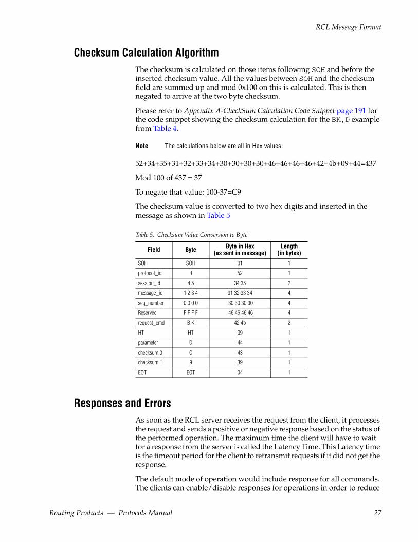
Checksum Calculation AlgorithmThe checksum is calculated on those items following SOH and before the inserted checksum value. All the values between SOH and the checksum field are summed up and mod 0x100 on this is calculated. This is then negated to arrive at the two byte checksum.
Please refer to Appendix A-CheckSum Calculation Code Snippet page 191 for the code snippet showing the checksum calculation for the BK,D example from Table 4.
Note The calculations below are all in Hex values.
52+34+35+31+32+33+34+30+30+30+30+46+46+46+46+42+4b+09+44=437
Mod 100 of 437 = 37
To negate that value: 100-37=C9
The checksum value is converted to two hex digits and inserted in the message as shown in Table 5
Table 5. Checksum Value Conversion to Byte
Field Byte Byte in Hex(as sent in message)
Length(in bytes)
SOH SOH 01 1
protocol_id R 52 1
session_id 4 5 34 35 2
message_id 1 2 3 4 31 32 33 34 4
seq_number 0 0 0 0 30 30 30 30 4
Reserved F F F F 46 46 46 46 4
request_cmd B K 42 4b 2
HT HT 09 1
parameter D 44 1
checksum 0 C 43 1
checksum 1 9 39 1
EOT EOT 04 1
Responses and ErrorsAs soon as the RCL server receives the request from the client, it processes the request and sends a positive or negative response based on the status of the performed operation. The maximum time the client will have to wait for a response from the server is called the Latency Time. This Latency time is the timeout period for the client to retransmit requests if it did not get the response.
The default mode of operation would include response for all commands. The clients can enable/disable responses for operations in order to reduce
Routing Products — Protocols Manual 27
Section 2 — Grass Valley Router Control Language
processing at the client end. The client can disable these responses by sending the RCL command BK,E,OFF.
In case of operations like take, protect, unprotect and salvo, positive response only indicates that the operation request has been passed onto the lower layers in the system. It does not indicate successful completion of the operation. The only way to find out if the operation has been successfully carried out is to query the status back on the specific entity on which the operation was performed. In case of clients who have subscribed for status changes on the entity, the change will be asynchronously notified.
Level 4 Error
The RCL level 4 error message is an RCL message with the following data. The header and trailer information is the same as any other RCL message.
<SOH><protocol_id><session_id><message_id><seq_number> <Reserved><Data><checksum><EOT>
Where <Data> is of the form ER<,error_code><,request_cmd>
ER The two ASCII characters ‘ER’
<,error_code> Two digit ASCII code defining the error detected at Level 4. Level 4 error codes are two digit hex num-bers, and are transmitted as two ASCII bytes, most significant byte first. “ER,00” signifies that the request was successfully executed and is not an error.
<,request_cmd> The two-letter request command which this message corresponds to.
[,data] Optional printable ASCII character providing addi-tional information about the error. In many cases, this data will be one of the parameters of the failed command (e.g., the incorrect dest_name). The datum delimiter is <HT> Horizontal Tab (0x09), and precedes each datum, including the first. (Examples show <HT> as comma.) A trailing <HT> following the last datum is sent to facilitate parsing by the client. Incoming control messages are buff-ered to maximize throughput.
Message Size and SequenceMessage size can grow quite large, both for commands and responses. For example, the TA (Request Take) command could grow large, depending on
28 Routing Products — Protocols Manual
RCL Message Format
the number of sources and levels specified. Long commands and responses may need to be segmented and sent in a sequence of messages rather than in one large message.
The seq_number indicates the sequence of this packet in the context of the whole message.
If <seq_flag = ASCII ‘0000’>, this is the last segment.
Many messages fit in a single packet. For these messages also, the sequence number is set to ‘0000’.
Messages are sent with entries intact, so each message makes complete sense on its own. Messages are not arbitrarily broken up without regard to data boundaries.
Level BitmapA level_bitmap is a 32 bit quantity where each bit represents the presence (=1) or absence (=0) of a particular level for that command or response. The least significant bit (right-most) represents Level #0. The most significant bit (left-most) represents Level #31. The QN,L command allows the user to find out the Level Names configured in the system.
The following example shows how level bitmap is constructed for a given set of levels.
Assume that a particular operation is to be performed on levels 0, 2, 3, 4, 5, 6, and 10. This information is rendered onto a 32 bit quantity as shown below.
Level Bitmap = 0000 0000 0000 0000 0000 0100 0111 1101 (Binary)
The equivalent hex message is shown below
Level Bitmap (Hex) = 0x 0000047D
These 8 hex digits are then converted to ASCII (=’0’,...’9’, ‘A’,...’F’) and sent with the most significant byte first. The hex digits ‘A’...’F’ can be sent as upper or lower case (‘a’...’f’).
Level Bitmap (Sent in ASCII) = 30 30 30 30 30 34 37 44
Area BitmapAn area_bitmap is a 64 bit quantity where each bit represents the presence (=1) or absence (=0) of a particular area for that command or response. The least significant bit (right-most) represents area index #0; the most signifi-cant bit (left-most) represents area index #63. The QN,A command allows the user to find out the Area Names configured in the system.
Routing Products — Protocols Manual 29

Section 2 — Grass Valley Router Control Language
-32)
-0)
The following example shows how an area bitmap is constructed for a given set of areas.
Assume that a particular operation is to be performed on areas 8, 13, 19, 24, 25, 28, and 32. This information is rendered onto a 64 bit quantity as shown:
Area Bitmap = 0000 0000 0000 0000 0000 0000 0000 0001 (Bits 63
(Binary) 0001 0011 0000 1000 0010 0001 0000 0000 (Bits 31
The equivalent hex message is:
Area Bitmap = 0x 00000001 13082100 (Hex)
These 8 hex digits are then converted to ASCII (=’0’,...’9’, ‘A’,...’F’) and sent with the most significant byte first. The hex digits ‘A’...’F’ can be sent as upper or lower case (‘a’...’f’).
Area Bitmap = 30 30 30 30 30 30 30 31 31 33 30 38 32 31 30 30 (Sent in ASCII)
Error CodesRCL server may return Level 2 NAK errors or Level 4 errors in case of request failures.
Level 2 NAK ErrorsNegative Acknowledgement (NAK) is generated due to communication related failures to a serial (RS-232 or RS-422 interface) client. These errors are not present for the Ethernet RCL interface.
An example of a Level 2 error is a Time Out Error. Time out interval begins upon reception of an SOH and is halted at the reception of an EOT. Time out interval is one (1) second for data rates from 2400 to 38.4k Baud.
For slower rates, time out is calculated as:
Time out (in seconds) = 2400/data rate.
For example, at 300 Baud, time out = 8 seconds (2400/300 = 8).
Level 2 (NAK) Error Code Descriptions
The following codes are sent with NAKs from the Router to the RCL client. The client is also responsible for sending NAKs to the Router when appro-
30 Routing Products — Protocols Manual
Error Codes
priate. However, if specific errors are reported with an external device’s NAK, they should be defined as:
<NAK> <error_code> <EOT>
<error code> is defined as a Hexadecimal number 71 - 79 (Table 6).
Table 6. RCL Protocol Level 2 NAK Error Codes
DecimalValue
HexadecimalValue Meaning Description
113 71 Buffer Size Exceeded The number of characters received since the last detected SOH is greater than the maximum RCL mes-sage length.
114 72 Buffer Not Available Input buffer full.
115 73 Reserved
116 74 Chip Level Error Error detected by UART such as parity error.
117 75 Checksum Error Packet had a bad checksum. Low Level errors such as framing, overrun, etc., are reported as checksum errors.
118 76 Time Out ErrorTime out interval is begun upon the reception of an SOH, and is halted at the reception of an EOT. Time out interval is one (1) second for data rates from 2400 to 38.4k Baud. For slower rates, time out is equal to 2400/data rate = time out in seconds. For example, at 300 Baud, time out = 8 seconds (2400/300 = 8).
119 77 Missing SOH EOT is detected without a preceding SOH.
120 78 Missing EOT No EOT detected in message.
121 79 Reserved
Level 4 ErrorsRCL Level 4 Errors occur when the commands are parsed and processed. Refer to page 195 for a list of Level 4 Error Codes.
A client can retrieve an explanation of the numeric error code at run time by using either the All Level 4 Errors or the Specific Level 4 Errors retrieval method.
All Level 4 Errors Retrieval
The client can request a list of all Level 4 error codes and definitions using the command QE.
The Router will respond with separate messages, each containing an error code and a description. Copy or print the error listing so that the explana-tions are at hand when error codes are received.
Specific Level 4 Errors Retrieval
Use the QE command with specific error code parameters.
Routing Products — Protocols Manual 31

Section 2 — Grass Valley Router Control Language
RCL Features
Synchronizing Requests and ResponsesMessage and session IDs are provided to facilitate the clients, to match RCL requests with the responses that are obtained from the server.
The client has to generate a message ID for every request it sends to the server. The client can use the message ID to match the response with request in a particular session. The RCL server copies the message ID (received as part of the request) onto the response. This mechanism makes it possible to associate the responses with the requests that triggered them, even in case of multiple responses. It must be noted here that message ID’s may wraparound in a session. Message IDs can range from 1 - to - 65535. This large range ensures that there will be no ambiguity in the response matching due to wraparound of message IDs. Message ID with value 0 is reserved for server use. The server will use this when it has to send error response and has not been able to extract a valid message ID. Notifications sent as part of subscription response will have its own sequence of message IDs with respect to a session.
Each RCL session is identified uniquely by a session ID. This session ID will be provided by the RCL server during the session initialization phase as described in the RCL connect mechanism. The client will have to use this session ID for any further request to the server. The server will copy the same as part of the response. Session ID value 0 is reserved. The RCL client will use this when it issues a RC. Since the session ID is given back to the client as part of response to RC, the client will need to use this default value for RC command.
Multiple Area SupportAreas create hierarchies within the control system and make it easier to group sources and destinations in a large system. Once an area is defined the sources and destinations in the area are identified using fully qualified names and indices. A source or destination name is said to be fully quali-fied if it is prefixed by “area name:”. Similarly source or destination indices need to be prefixed with “area index:” to make them fully qualified. Some RCL commands also take an optional parameter called Area Bitmap to specify a set of areas on which a particular request is intended for. Please refer to the Area Bitmap on page 29.
Subscription SupportSubscription is a mechanism through which RCL clients can register for notifications regarding configuration and status information. Whenever
32 Routing Products — Protocols Manual
RCL Features
these parameters change, the client is notified asynchronously by the RCL server. RCL facilities for subscription can be described in terms of the fol-lowing categories.
• Status change subscriptions
• Configuration change subscriptions
The subscription sequence and the commands used for this are introduced below. The command syntax and response is described in Client Subscrip-tion Message Descriptions on page 81. The way these commands (and their parameters) are used is explained in Subscription Commands Usage on page 83.
• The client after establishing connection with the server can subscribe for any of the information. The Subscribe (SB) command should be used for this support and is described in SB – Subscribe on page 81. Once the subscription request is received, the server confirms the subscrip-tion registration by issuing an ER,00 command. If the subscription request fails, an appropriate ER,nn message is generated. (Where nn is the two-digit error code sent back by the server identifying the cause of this failure.)
• The client can at any point decide to unsubscribe for a particular request that it had subscribed earlier. The Unsubscribe (UB) command should be used for this and is described in UB – Unsubscribe Request on page 81. When an unsubscribe request is received the server confirms the un-subscription by issuing an ER,00 command. If the unsubscribe request fails, an appropriate ER,nn message is generated. (Where nn is the two-digit error code sent back by the server identifying the cause of this failure.)
• The server sends an asynchronous notification (NY) to the client when-ever the subscribed status/configuration information changes are reported in the system.
The RCL server retains the subscriptions for each client till the client is con-nected. However, if a refresh rate is configured for the RCL client through the RCL Client Configuration screen of the OUI, then the subscriptions are retained only as long as the RCL Client refreshes the connection within the refresh timeout period specified. A refresh rate of zero means that the sub-scriptions are retained as long as the client remains connected. The sub-scriptions for all the clients are dropped in case of server reboot. In this case, RCL server will send a command called RCL Announce (RN) to the con-nected clients indicating that the client should resend the subscriptions to continue receiving the notifications.
Routing Products — Protocols Manual 33
Section 2 — Grass Valley Router Control Language
Exclusion Set SupportThe mechanism of exclusion sets (area, destination and level exclusion sets) can be applied to RCL clients. The exclusion sets to be used by any RCL client is configured at the system level (outside the scope of RCL). Any des-tination, area or level that is excluded for a particular RCL client is not visible to it through any operation. For example, when a client queries for the list of destinations, those destinations that are excluded are not returned.
Whenever the exclusion set changes, if the client has subscribed for notifi-cation, the client is informed about the change and needs to reinitialize its operational set of sources and destinations. These are intimated as config-uration change notification. The BK,F flags described in Table 12 will also be set to reflect the changes in the configured names applicable to the client due to changed exclusion sets. The clients can choose to poll it at any point to know what has changed and get the information accordingly.
Refreshing and Maintaining ProtectsIf an automation client protects particular destinations on the Router, the client is responsible for refreshing those protects periodically or the pro-tects will be dropped by the RCL Server.
The refresh interval can be disabled (= 0), or set ≤ 255 seconds. If any Level 4 command is not received within this periodicity, the RCL Server decides that the external device is no longer active and sends a device-delete message to the system. As a result, all protects (and Subscriptions) cur-rently held by this automation client are dropped.
The refresh interval can be set from the client config screen of the OUI. The BK, with no parameters, has no side effects and can be used to keep protects refreshed in the absence of other Level 4 command activity. Level 2 ACKs from the external automation clients do not refresh the protects.
Protects issued by a client are also dropped when the RCL Server loses the connection with the client. In case of serial clients, if the connection is not closed gracefully (using RD command) protects remain till the next connect request from the same client. These are cleared during the next RCL connect (using RC command) from the client.
34 Routing Products — Protocols Manual

RCL Features
The configuration flags on the user interface with respect to protect func-tion are:
Maintain protect persistence
When this flag is set, any protects performed by the client will be maintained across sessions of the same client. If this is not set, protects that a client has issued will be dropped when connection is lost with the client or when the client fails to refresh the pro-tects within the configured time interval.
Protect Override When this flag is set for a client, the client can over-ride the protect that had been performed on a desti-nation by a different control point and modify the destination status. For example if client A has pro-tected destination Mydest, another client B with the protect override set can perform a take onto the same destination.
Routing Products — Protocols Manual 35

Section 2 — Grass Valley Router Control Language
RCL Message Categories
Client Originated MessagesThe RCL Protocol messages originating from a client are in Table 7.
Table 7. Client Originated Messages
Command DescriptionExpectedServer
Response
AS - Assign Source (page 39) Assign a source to destination ER, 00
BK - Background Activities (page 40) Query system configuration and flags KB
CA - Change Alias (page 42) Change the source or destination alias name ER, 00
CH - Request Chop (page 43) Initiates chopping between specified sources. ER, 00
CM - Commit Alias Changes (page 44) Commit the source or destination alias changes to network ER, 00
DA - De-Assign Source (page 45) De-assign a source from a destination ER, 00
GA - Get Alias Name (page 45) Get the source or destination alias name with configuration information AG
GT – Get Current VITC Time (page 46) Get the current VITC time from the server in HHMMSSFF format as ASCII charac-ters. TG
PI - Protect by Index (page 47) Protects a specified destination index. ER,00
PR - Protect (page 47) Protects a specific destination from other control points ER, 00
QA- Query Machine Assignment Status (page 48) Query machine assignment status AQ
QB - Query Alarm Definitions (page 48) Query the list of supported alarms. BQ
QC - Query Combined Destination Status (page 50) Queries source status on combined levels of the destination. The combined levels are interpreted with respect to the first level on which the destination is present. The status returned back will have the source taken to the destination on the first level on which the destination is present. This will also specify the other levels on this source has been taken to.
CQ
QD - Query Destination Status (page 51) Queries sources assigned to destinations by destination name. DQ
QE - Query Error Definition (page 53) Queries text describing a particular error code. EQ
QH - Query Alarm Status (page 53) Query the alarm status HQ
QI - Query Destination Status on a Specific Level by Index (page 55)
Queries sources assigned to destinations by Destination index and Level Index. IQ
QJ - Query Destination Status by Index (page 55) Queries sources assigned to destinations by Destination Index for all levels. JQ
QK - Query Destination Status by Index with Tie Lines Used (page 57)
Query the destination status by destination index for all levels with tie line infor-mation KQ
QM - Query Monitor Status (page 58) Query monitor status for specified monitor MQ
Qm- Query Monitors Status with Level Information (page 59)
Query monitor status along with level information mQ
QN - Query Names (page 64) Checks names associated with Sources, Destinations, Levels, Salvos, Areas or TieLines. NQ
QP - Query Salvo Details along with Protect information (page 59)
Query salvo details along with protect information PQ
QR - Query Room Details (page 60) Query the included destinations, assigned tie lines and linked rooms for specified room RQ
Qs - Query Salvo Element with Operation Type (page 61) Query salvo elements information with operation type. sQ
QT - Query Date & Time (page 62) Query system date and time information ST
QU - Query Audio Attributes (page 62) Query the audio attributes of a destination on audio levels. UQ
36 Routing Products — Protocols Manual
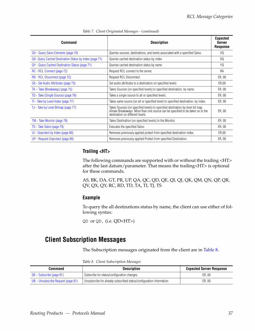
RCL Message Categories
Trailing <HT>
The following commands are supported with or without the trailing <HT> after the last datum/parameter. That means the trailing<HT> is optional for these commands.
AS, BK, DA, GT, PR, UP, QA, QC, QD, QE, QI, QJ, QK, QM, QN, QP, QR, QV, QX, QY, RC, RD, TD, TA, TI, TJ, TS
Example
To query the all destinations status by name, the client can use either of fol-lowing syntax:
QD or QD, (i.e. QD<HT>)
Client Subscription MessagesThe Subscription messages originated from the client are in Table 8.
Table 8. Client Subscription Messages
Command Description Expected Server Response
SB – Subscribe (page 81) Subscribe for status/configuration changes. ER, 00
UB – Unsubscribe Request (page 81) Unsubscribe for already subscribed status/configuration information ER, 00
QV - Query Salvo Elements (page 70) Queries sources, destinations, and levels associated with a specified Salvo. VQ
QX- Query Cached Destination Status by Index (page 71) Queries cached destination status by index XQ
QY - Query Cached Destination Status (page 71) Queries cached destination status by name YQ
RC - RCL Connect (page 72) Request RCL connect to the server. RA
RD - RCL Disconnect (page 72) Request RCL Disconnect. ER, 00
SA - Set Audio Attributes (page 73) Set audio attributes to a destination on specified levels ER,00
TA – Take (Breakaway) (page 75) Takes Sources (on specified levels) to specified destination, by name. ER, 00
TD - Take (Single Source) (page 76) Takes a single source to all or specified levels. ER, 00
TI - Take by Level Index (page 77) Takes same source (on all or specified level) to specified destination, by index. ER, 00
TJ - Take by Level Bitmap (page 77) Takes Sources (on specified levels) to specified destination by level bit map. Allows Breakaways. More than one source can be specified to be taken on to the destination on different levels.
ER, 00
TM - Take Monitor (page 78) Takes Destination (on specified levels) to the Monitor. ER, 00
TS - Take Salvo (page 79) Executes the specified Salvo. ER, 00
UI - Unprotect by Index (page 80) Removes previously applied protect from specified destination index. ER,00
UP - Request Unprotect (page 80) Removes previously applied Protect from specified Destination. ER, 00
Table 7. Client Originated Messages - (continued)
Command DescriptionExpectedServer
Response
Routing Products — Protocols Manual 37

Section 2 — Grass Valley Router Control Language
Server Originated MessagesThe RCL Protocol messages originated from the server are in Table 9.
Table 9. Server Originated Messages
Command DescriptionExpected
ClientResponse
NY – Notification (page 82) An asynchronous Notification sent whenever the subscribed status/configuration information changes ER, 00
RD - RCL Disconnect (page 83) Request RCL Disconnect. ER, 00
RN - RCL Announce (page 83) Server announce at start up to facilitate clients to refresh subscription requests. None.
RCL Message SpecificationsThe following specifications apply to all the RCL message commands.
Note Leading zeros are used if necessary so as to keep the area index length to 2 digits and destination/source index length to four digits.
fullqual_dest_name Specifies the fully qualified destination name. This is of the form area_name:destination_name.
Example, for a destination called GRAFIX in area NEWS, the fullqual_dest_name is NEWS:GRAFIX.
fullqual_src_name Specifies the fully qualified source name. This is of the form area_name:source_name.
Example, for a source called VTR2 in area SPORTS, the fullqual_src_name is SPORTS:VTR2.
fullqual_dest_index Specifies the fully qualified destination index. This is of the form area_index:destination_index.
38 Routing Products — Protocols Manual
Client Originated Message Descriptions
Example, for a destination with index 127 in area with index 2, the fullqual_dest_index is 02:007F. (Use the hexadecimal values for index 127 which is 00F7 and index 2 which is 02.)
fullqual_src_index Specifies the fully qualified source index. This is of the form area_index:source_index.
Example, for a source with index 64 in area with index 1, the fullqual_dest_index is 01:0040. (Use the hexadecimal values for index 64 which is 0040 and index1 which is 01.)
Every RCL Client may configure a default area through the client configu-ration screen of the OUI. If the field ‘area_name:’/ ‘area_index:’ is omitted in the fully qualified name, then the default configured area is used by the RCL Server to qualify the Source/Destination name/index.
time_stamp – VITC Time stamp to be provided by the clients for determin-istic operations. The time stamp is specified as part of the commands in HHMMSSFF format.
In case of non time stamped operations this field can be left blank. The time stamp field is used to specify the VITC time at which the operation (take, chop or protect) should be performed on the router. The operation will be carried out exactly on the specified frame. This time should at least be 6 frames more than the time at which the command is received by the RCL Server. Thus the client should take into account the transit time (Via Ethernet or serial medium) while setting this time stamp value. There is also an upper limit on the time that can be specified by the client. The time specified should not be more than 100 frames from the time at which the RCL Server receives the request.
Client Originated Message Descriptions
AS - Assign SourceThe AS command facilitates to assign one or more sources to a specific des-tination. The command shall accept sources and destinations from the same area only.
Routing Products — Protocols Manual 39

Section 2 — Grass Valley Router Control Language
CommandAS,fullqual_dest_name,nbr_srcs[,fullqual_src_name1… fullqual_src_nameN]
Response
The AS Command will get an ER,00 response on success and an ER,nn (nn>0) on failure indicating the reason of failure.
BK - Background ActivitiesThe BK command can be sent to query system configuration and flags
CommandBK[,parameter [,mask]]
One parameter can be specified per BK call. Each parameter consists of a single, case sensitive character, defined in Table 10.
Table 10. BK Command Parameters
Parameter Description
A Clears the flags associated with the QA command. After BK,A is sent, the next QA command will result in the server sending the assignment sta-tus for all the destinations.
N Return device name.
R Return software revision number.
T Return software title with version.
t Return protocol title with version.
F Queries the configuration flags. Refer to Table 12 for the meaning of these flags.
f Clears the configuration flags specified in the mask. Refer to Table 12 for bit definition of the mask.
D Clears the flags associated with the QD command. After BK,D is sent, the next QD command will result in the server sending all destination statuses.
P Queries the client specific configuration parameters specified on the graphical user interface.
E Returns whether to send the positive responses for operations. The client can also use this command to set/stop the positive responses for oper-ations by sending BK,E,ON or BK,E,OFF respectively.
d Returns the name of the client specified on the graphical user interface.
2 This command is used by the serial client to ensure that the RCL server is running. The server will respond back with a level 2 acknowledgement. This command is for the serial interface only.
U Clears the flags associated with the QU command. After BK,U is sent, the next QU command will result in the server sending all destinations attributes statuses.
H Clears the flags associated with the QH command. After BK,H is sent, the next QH command will result in the server sending all alarms status.
No parameter, no side effects. Can be used to refresh Protects and Subscriptions
40 Routing Products — Protocols Manual
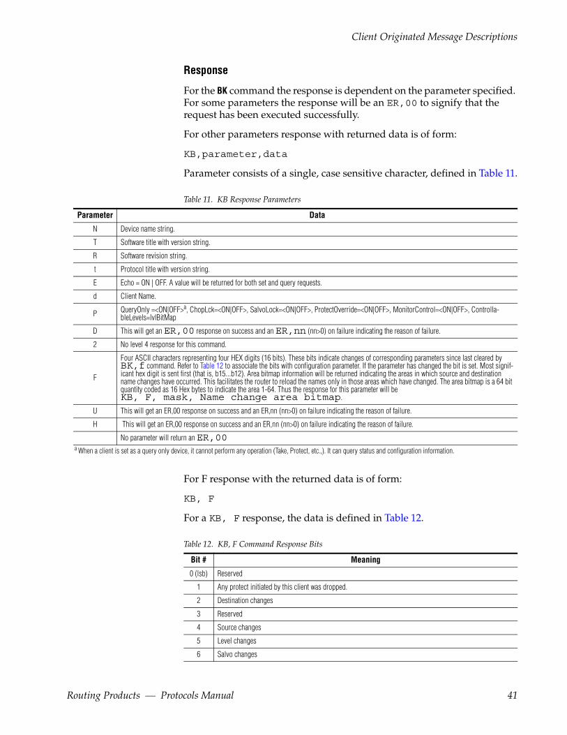
Client Originated Message Descriptions
Response
For the BK command the response is dependent on the parameter specified. For some parameters the response will be an ER,00 to signify that the request has been executed successfully.
For other parameters response with returned data is of form:
KB,parameter,data
Parameter consists of a single, case sensitive character, defined in Table 11.
Table 11. KB Response Parameters
Parameter Data
N Device name string.
T Software title with version string.
R Software revision string.
t Protocol title with version string.
E Echo = ON | OFF. A value will be returned for both set and query requests.
d Client Name.
P QueryOnly =<ON|OFF>a
a When a client is set as a query only device, it cannot perform any operation (Take, Protect, etc.,). It can query status and configuration information.
, ChopLck=<ON|OFF>, SalvoLock=<ON|OFF>, ProtectOverride=<ON|OFF>, MonitorControl=<ON|OFF>, Controlla-bleLevels=lvlBitMap
D This will get an ER,00 response on success and an ER,nn (nn>0) on failure indicating the reason of failure.
2 No level 4 response for this command.
F
Four ASCII characters representing four HEX digits (16 bits). These bits indicate changes of corresponding parameters since last cleared by BK,f command. Refer to Table 12 to associate the bits with configuration parameter. If the parameter has changed the bit is set. Most signif-icant hex digit is sent first (that is, b15...b12). Area bitmap information will be returned indicating the areas in which source and destination name changes have occurred. This facilitates the router to reload the names only in those areas which have changed. The area bitmap is a 64 bit quantity coded as 16 Hex bytes to indicate the area 1-64. Thus the response for this parameter will be KB, F, mask, Name change area bitmap.
U This will get an ER,00 response on success and an ER,nn (nn>0) on failure indicating the reason of failure.
H This will get an ER,00 response on success and an ER,nn (nn>0) on failure indicating the reason of failure.
No parameter will return an ER,00
For F response with the returned data is of form:
KB, F
For a KB, F response, the data is defined in Table 12.
Table 12. KB, F Command Response Bits
Bit # Meaning
0 (lsb) Reserved
1 Any protect initiated by this client was dropped.
2 Destination changes
3 Reserved
4 Source changes
5 Level changes
6 Salvo changes
Routing Products — Protocols Manual 41

Section 2 — Grass Valley Router Control Language
Example of the Use of Flag Bits
The user queries RCL using BK,F. They receive a reply with parameter bit #4 set to indicate that there has been a change (addition, or modification, or deletion) to the system source name table. The server will also send the source change area bit map (as part of the KB,F response) indicating the areas on which the source information has changed. The client should now issue a QN,S, source_area_bitmap command to get the new source information. The source change area bit map returned with KB,F can be used by the client as part of the QN,S command. The client next uses the BK,f, mask (where mask bit #4 = 1) command to clear bit #4 from the mask. The client again queries using BK,F. The reply shows that bit #4 = 0, indicating that the source name list just downloaded is current.
Do not confuse the flags discussed with the f & F options with those dis-cussed with the D option. The QD command allows the user to download incremental changes in the Destination Status tables. The D option of the BK command clears the bit arrays that keep track of these incremental changes. This re-synchronizes the router data base (for Destination Status) if the external device resets.
CA - Change AliasChange the source or destination aliases. Changing the source \ destina-tion alias name is a two-step process. The RCL client can send the request to change the source \ destination alias of multiple sources \ destinations using the command CA. However these changes are not committed and broadcast to the network immediately. The client needs to send the RCL command CM to commit and broadcast the alias name changes.
Table 13. CA Parameters
Parameter Meaning
SA Source Alias
DA Destination Alias
7 Reserved
8 Area changes
9 Client Name changes
10 - 14 Reserved
15 Reserved
f, mask This will get an ER,00 response on success and an ER,nn (nn>0) on failure indicating the reason of failure.
Table 12. KB, F Command Response Bits - (continued)
Bit # Meaning
42 Routing Products — Protocols Manual
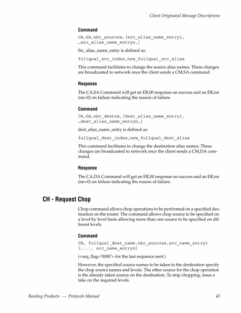
Client Originated Message Descriptions
CommandCA,SA,nbr_sources,[src_alias_name_entry1, …src_alias_name_entryn,]
Src_alias_name_entry is defined as:
fullqual_src_index,new_fullqual_src_alias
This command facilitates to change the source alias names. These changes are broadcasted to network once the client sends a CM,SA command.
Response
The CA,SA Command will get an ER,00 response on success and an ER,nn (nn>0) on failure indicating the reason of failure.
CommandCA,DA,nbr_destns,[dest_alias_name_entry1, …dest_alias_name_entryn,]
dest_alias_name_entry is defined as:
fullqual_dest_index,new_fullqual_dest_alias
This command facilitates to change the destination alias names. These changes are broadcasted to network once the client sends a CM,DA com-mand.
Response
The CA,DA Command will get an ER,00 response on success and an ER,nn (nn>0) on failure indicating the reason of failure.
CH - Request ChopChop command allows chop operations to be performed on a specified des-tination on the router. The command allows chop source to be specified on a level by level basis allowing more than one source to be specified on dif-ferent levels.
CommandCH, fullqual_dest_name,nbr_sources,src_name_entry1 [,..., src_name_entryn]
(<seq_flag=’0000’> for the last sequence sent.)
However, the specified source names to be taken to the destination specify the chop source names and levels. The other source for the chop operation is the already taken source on the destination. To stop chopping, issue a take on the required levels.
Routing Products — Protocols Manual 43

Section 2 — Grass Valley Router Control Language
To specify a chop operation, first Take sources on levels to the destination, then Chop to the same destination with the chop sources on the required levels.
Response
This will get an ER,00 response on success and an ER,nn (nn>0) on failure, indicating the reason of failure.
dest_name Destination to be taken to.
nbr_sources Number of following entries (must be at least one).
src_name_entryn is defined as:
fullqual_src_name,level_bitmap
Example
The following command will chop a source named VTR_W_2 in area NEWS on levels with indices 2 and 3 and source VTR_M_2 in area NEWS on level index 1 to the destination VTR_B_1 in area NEWS.
CH,NEWS: VTR_B_1,2,NEWS: VTR_W_2,0000000C, NEWS: VTR_M_2,00000002
CM - Commit Alias ChangesCommit the source or destination alias changes allowing the broadcast of alias changes onto the network.
Table 14. CM Parameters
Parameter Meaning
SA Source Alias
DA Destination Alias
CommandCM,SA
Commit the source alias changes and broadcast the same onto the network.
Response
The CM,SA Command will get an ER,00 response on success and an ER,nn (nn>0) on failure indicating the reason of failure.
44 Routing Products — Protocols Manual
Client Originated Message Descriptions
Command CM,DA
Commit the destination alias changes and broadcast the same onto the net-work.
Response
The CM,DA Command will get an ER,00 response on success and an ER,nn (nn>0) on failure indicating the reason of failure.
DA - De-Assign SourceThe DA command facilitates to de-assign one or more sources from a spe-cific destination. The command shall accept sources and destinations from the same area only.
CommandDA,fullqual_dest_name,nbr_srcs[,fullqual_src_name1… fullqual_src_nameN]
Response
The DA Command will get an ER,00 response on success and an ER,nn (nn>0) on failure indicating the reason of failure.
GA - Get Alias NameThis command shall return the alias name for source or destination based on parameter along with source or destination configuration information.
Table 15. GA Parameters
Parameter Meaning
SN Source Name
SI Source Index
DN Destination Name
DI Destination Index
CommandGA,SN,fullqual_source_name
This command shall return the source alias name along with source infor-mation for the specified source (by Name).
Routing Products — Protocols Manual 45
Section 2 — Grass Valley Router Control Language
ResponseAG,SN,fullqual_src_name,fullqual_src_index, TieLine_Type,Level_Bitmap ,fullqual_src_alias
CommandGA,SI,fullqual_source_index
This command shall return the source alias name along with source infor-mation for the specified source (by Index).
ResponseAG,SI,fullqual_src_name,fullqual_src_index, TieLine_Type,Level_Bitmap ,fullqual_src_alias
CommandGA,DN,fullqual_dest_name
This command shall return the destination alias name along with destina-tion information for the specified destination (by Name).
ResponseAG,DN,fullqual_dest_name,fullqual_dest_index, TieLine_Type,Level_Bitm ap,fullqual_dest_alias
CommandGA,DI,fullqual_dest_index
This command shall return the destination alias name along with destina-tion information for the specified destination (by Index).
ResponseAG,DI,fullqual_dest_name,fullqual_dest_index, TieLine_Type,Level_Bitmap,fullqual_dest_alias
GT – Get Current VITC TimeGet the current VITC time from the server in HHMMSSFF format as ASCII characters
CommandGT
46 Routing Products — Protocols Manual

Client Originated Message Descriptions
ResponseTG, HHMMSSFF
HH = Hours 00 … 23
MM = Minutes 00 … 59
SS = Seconds 00 … 59
FF = Frames 00 … 30 for NTSC 00 … 25 for PAL
PI - Protect by IndexProtect command allows the specified destination index to be protected from any source changes on the specified level. The level bitmap is an optional parameter which if not specified results in an all level protect.
CommandPI,fullqual_dest_index[,level_bitmap]
Response
This will get an ER,00 response on success and an ER,nn (nn>0) on failure indicating the reason of failure.
Example
To protect a destination at index 0x0000 in area index 0x02 on the fourth and fifth levels only, the command is as shown below:
PI,02:0000 ,00000018
PR - ProtectProtect command allows the specified destination to be protected from any source changes on the specified level. The command requires a level_bitmap to be specified on which protect should be performed.
CommandPR,fullqual_dest_name,level_bitmap
Routing Products — Protocols Manual 47

Section 2 — Grass Valley Router Control Language
Response
This will get an ER,00 response on success and an ER,nn (nn>0) on failure indicating the reason of failure.
Example
To protect a destination named PDR2 in area POSTPRD on levels with indices 3 and 4 the client should issue the following command
PR,POSTPRD:PDR2,00000018
QA- Query Machine Assignment StatusQuery the current assignments on a specific destination or for all the desti-nations configured in system.
CommandQA
The assignment status is returned for all the destinations for which assign-ment have changed since the last time status was sent. The BK,A command can be sent before this request to force return of all destination assignment status.
CommandQA,fullqual_dest_name
The assignment status will be returned only for the requested Destination.
QB - Query Alarm DefinitionsThe command allows a client to query the supported alarm definitions. Alarm definitions are not the same for all devices. For example, some hard-ware devices support AC power alarm and some will not.
The QB command can have different command syntaxes.
CommandQB
The definitions for all supported alarms are returned. The response can result in a sequence of messages for each of many alarms.
Command QB[,<alarm ID>]
48 Routing Products — Protocols Manual
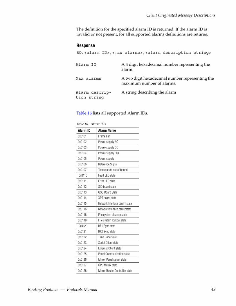
Client Originated Message Descriptions
The definition for the specified alarm ID is returned. If the alarm ID is invalid or not present, for all supported alarms definitions are returns.
ResponseBQ,<alarm ID>,<max alarms>,<alarm description string>
Alarm ID A 4 digit hexadecimal number representing the alarm.
Max alarms A two digit hexadecimal number representing the maximum number of alarms.
Alarm descrip-tion string
A string describing the alarm
Table 16 lists all supported Alarm IDs.
Table 16. Alarm IDs
Alarm ID Alarm Name
0x0101 Frame Fan
0x0102 Power-supply AC
0x0103 Power-supply DC
0x0104 Power-supply Fan
0x0105 Power-supply
0x0106 Reference Signal
0x0107 Temperature out of bound
0x0110 Fault LED state
0x0111 Error LED state
0x0112 SIO board state
0x0113 GSC Board State
0x0114 XPT board state
0x0115 Network Interface card 1 state
0x0116 Network Interface card 2state
0x0118 File system cleanup state
0x0119 File system lockout state
0x0120 RF1 Sync state
0x0121 RF2 Sync state
0x0122 Time Code state
0x0123 Serial Client state
0x0124 Ethernet Client state
0x0125 Panel Communication state
0x0126 Mirror Panel server state
0x0127 CPL Matrix state
0x0128 Mirror Router Controller state
Routing Products — Protocols Manual 49

Section 2 — Grass Valley Router Control Language
QC - Query Combined Destination StatusQuery the status on combined levels of the destination. The combined levels is interpreted with respect to the first level on which the destination is present. The status returned back will have the source taken to the desti-nation on the first level on which the destination is present. This will also specify information of the other levels on which this source has been taken to.
Command
The QC command can have different command syntaxes.
QC In this case, destination status is returned for all destinations for which status has changed since the last time status was sent. Destination status is returned for all levels (for the changed as well as unchanged levels) which have status. The BK,D command can be sent before this request to force return of all destination status.
QC[,area_bitmap:] In this case the destination status is returned for all destinations in the areas specified by the area bitmap for which status has changed since the last time status was sent to the client.
QC[,fullqual_dest_name]
In this case the status for the requested destination will be returned
Response
CQ,fullqual_dest_name,dst_level_bitmap [,src_name_entry1]
(<seq_flag=’0000’> for the last sequence sent.)
dst_level_bitmap Describes the levels configured for destination.
0x0129 Router Engine state
0x0130 Watchdog Action
Table 16. Alarm IDs
Alarm ID Alarm Name
50 Routing Products — Protocols Manual

Client Originated Message Descriptions
src_name_entry1 is defined as:
<‘N’|’P’>,<‘N’|’C’>, fullqual_src_name,level_bitmap, [prot_device_name], [fullqual_chop_src_name]
Parameters for this response are in Table 17.
Table 17. QC Response Parameters
Parameter Meaning
’N’ |’P’ Not-protected or Protected
’N’ | ‘C’ Not-chopping or Chopping
fullqual_src_name The source currently taken to the destination on the first level on which the destination is present.
level_bitmap Describes the levels of that destination which the source is on
prot_device_name The device currently holding the protect. If the destination is not protected, or the device name is unknown, the field is left blank.
fullqual_chop_src_name The name of the source chopping to this destination. The fully qualified chop source name will be returned as "Chopping".
If there is no source currently on the first level defined for the destination, the fullqual_src_name part of the src_name_entry will be blank in the response.
If the query is made for all the areas or all the destinations in a given area, the response will contain only those destination whose status has changed since the last query. If there are no destination status changes since the last query, the response will be a blank CQ. That is, no destination status will accompany the CQ.
QC (with no dest_name specified) is one of several commands whose response can be more than one message sequence. QC with no parameter can result in a sequence of messages for each of many destinations.
Example
To query the combined status of the destination PDR2 in area POSTPRD the following command syntax should be used.
QC,POSTPRD:PDR2
QD - Query Destination StatusQuery the destination status. This query returns status of the requested destination including the sources that have been taken to the destination along with the associated levels for the sources.
Routing Products — Protocols Manual 51

Section 2 — Grass Valley Router Control Language
Command
QD can have different command syntaxes.
QD In this case, destination status is returned for all destinations for which status has changed since the last time status was sent. Destination status is returned for all levels (for the changed as well as unchanged levels), which have status. The BK,D command can be sent before this request to force return of all destina-tion status.
QD[,fullqual_dest_name] In this case the status for the requested destination will be returned
QD[,area_bitmap:] In this case the destination status infor-mation is returned for all destinations in the areas specified by the area bitmap for which status has changed since the last time status was sent to the client.
ResponseDQ, fullqual_dest_name,nbr_sources[,src_name_entry1,...,src_name_entryn]
(<seq_flag=’0000’> for the last sequence sent.)
nbr_sources Number of sources on that destination which are being reported in this message sequence. If there are no sources on this destination at any of its levels, nbr_sources = 0 will be returned.
src_name_entryn is defined as:
<‘N’|’P’>,<‘N’|’C’>, fullqual_src_name,level_bitmap,[prot_device_name], [fullqual_chop_src_name]
Data for this response is identical to the QC command response described previously.
The fully qualified chop source name will be returned as "Chopping
If there are no sources currently on some of the levels defined for the desti-nation, no information is reported for those levels.
If the query is made for all the areas or all the destinations in a given area, the response will contain only those destination whose status has changed
52 Routing Products — Protocols Manual
Client Originated Message Descriptions
since the last query. If there are no destination status changes since the last query, the response will be a blank DQ. That is, no destinations status will accompany the DQ.
QD (with no dest_name specified) is one of several commands whose response can be more than one message sequence. QD with no parameter can result in a sequence of messages for each of many destinations.
Example
Suppose the index of area INGEST is 1 and index of POSTPROD is 5, then the corresponding area bitmap will be 0x0000000000000022
To query the status of all the destinations in areas INGEST and POSTPROD, the following command syntax should be used.
QD, 0000000000000022:
QE - Query Error DefinitionError messages returned by the server are identified by a two byte code. The QE command allows the user to retrieve the text describing Level 4 error codes. Level 2 error codes (associated with NAKs) are described in Level 2 (NAK) Error Code Descriptions on page 30.
CommandQE,[error_code]
error_code A 2 hex digit error code (to be sent in ASCII format)
Response
If the error_code is specified along the query, the description for that error_code is returned. Else, the description for all the error codes are returned.
EQ,error_code,error_definition_string
(<seq_flag=’0000’> for the last sequence sent.)
QH - Query Alarm StatusThe QH command queries for the alarm status.
CommandQH
Routing Products — Protocols Manual 53
Section 2 — Grass Valley Router Control Language
The alarm status is returned for all alarms for which status has changed since the last time status was sent. The alarm status contains the faulty and active status. The BK, H command can be sent before this query to force a return of all the alarm status.
ResponseHQ, Nbr_entries,alarm_entry1,….alarm_entryN.
Nbr_entries indicates the number of alarm entries present in response.
Alarm_entry is defined as: AlarmID, AlarmStateID, AlarmParameter
where
Alarm ID is a 4 digit hexadecimal number representing the alarm
AlarmStateID is a single digit value.1 represents a faulty state and 0 repre-sents no faulty state.
AlarmParameter is a string representing the module generating the alarm
Example
If the first fan in the frame is faulty, the response will be as shown below
HQ,01, 0101 ,1,1
CommandQH,AC
Query active alarm status for faults only.
ResponseHQ,AC,Nbr_entries,alarm_entry1,….alarm_entryN.
Nbr_entries indicates the number of alarm entries present in the response.
Alarm_entry is defined as: AlarmID, AlarmStateID, AlarmParameter
Alarm ID is a 4 digit hexadecimal number representing the alarm
AlarmStateID is a single digit value.1 represents a faulty state and 0 repre-sents no faulty state.
AlarmParameter is a string representing the module generating the alarm
Example
If the first fan is faulty and the second power supply is faulty, the response will be as shown below:
54 Routing Products — Protocols Manual

Client Originated Message Descriptions
HQ,AC,02,0101,0,1,0102,1,1
QI - Query Destination Status on a Specific Level by Index Query the destination status on a specific level using the destination index. This query returns the source that has been taken to the destination on the specified level. Both the destination and level are specified using indices.
CommandQI, fullqual_dest_index,lvlIndex
ResponseIQ, fullqual_dest_index,lvlIndex,<‘N’|‘P’>,<‘N’|‘C’>, fullqual_src_index, [fullqual_chop-SrcIndex]
All indexes (dstIndex, lvlIndex, srcIndex) are zero–based hex num-bers. These indexes refer to the logical index for each entity, not to the phys-ical port number. However, the system can be configured so that port numbers are identical to index numbers. There is no disconnect index number, all indexes refer to configured entities. Valid indexes and their association with specific names can be determined using the commands: QN, ID; QN, IS; QN, L; QN, IA.
The source index contains specific values for the "Undef","No_xpt", "Parked" and "No_Mtrx". Refer the table Table 19 on page 57.
The fully qualified chop source index will be returned as "0xFFFA".
Example
Suppose the index of POSTPROD is 3, and the index of PROFILE1 is 399. Then the corresponding fullqual_dest_index is 03:018F. Suppose the level index of video is 0.
To query the status of destination PROFILE1 in area POSTPROD, on video level the following command syntax should be used.
QI,03:018F,00
QJ - Query Destination Status by Index Query the destination status by index. This query returns the sources that have been taken to the destination along with the levels on which the source is associated. This command is the index equivalent QD.
Routing Products — Protocols Manual 55
Section 2 — Grass Valley Router Control Language
Command
QJ can have different command syntaxes.
QJ In this case, destination status is returned for all destinations for which status has changed since the last time status was sent. Destination status is returned for all levels (for the changed as well as unchanged levels), which have status. The BK,D command can be sent before this request to force return of all destination status.
QJ[,fullqual_dest_index] In this case the status for the requested destination will be returned
QJ[,area_bitmap:] In this case the destination status is returned for all destinations in the areas specified by the area bitmap for which status has changed since the last time status was sent to the client.
ResponseJQ, fullqual_dest_index,nbr_sources [,src_name_entry1,..., src_name_entryn]
(<seq_flag=’0000’> for the last sequence sent for a particular destination status.)
nbr_sources Number of sources on that destination which are being reported in this message sequence. If there are no sources on this destination at any of its levels, nbr_sources = 0 will be returned.
src_name_entryn is defined as:
<‘N’|’P’>,<‘N’|’C’>,fullqual_src_index, level_bitmap,[prot_device_name], [fullqual_chop_src_index]
Parameters for this response are in Table 18.
Table 18. QJ Command Response Parameters
Parameter Meaning
’N’ |’P’ Not-protected or Protected
’N’ | ‘C’ Not-chopping or Chopping
56 Routing Products — Protocols Manual
Client Originated Message Descriptions
All indexes (dstIndex, lvlIndex, srcIndex) are zero–based hex num-bers. These indexes refer to the logical index for each entity, not to the phys-ical port number. However, the system can be configured so that port numbers are identical to index numbers. There is no disconnect index number, all indexes refer to configured entities. Valid indexes and their association with specific names can be determined using the commands: QN, ID; QN, IS; QN, L; QN, IA.
If there are no sources currently on some of the levels defined for the desti-nation, no information is reported for those levels.
If the query is made for all the areas or all the destinations in a given area, the response will contain only those destination whose status has changed since the last query. If there are no destination status changes since the last query, the response will be a blank JQ. That is, no destinations status will accompany the JQ.
Example
To query the status of all the destinations in all the areas, the following command syntax should be used.
QJ
QK - Query Destination Status by Index with Tie Lines UsedQuery the destination status along with the tie lines used. This query shall return the sources that have been taken to the destination along with the tie lines (if any) used and the levels on which the Source is associated.
QK can have the different command syntaxes.
fullqual_src_index The source (in the area specified by area index :) currently taken to the destination. Refer the Table Table 19 for specific source indices for "Undef","No_xpt" ,"Parked" and "No_Mtrx"
level_bitmap Describes the levels of that destination for which the source is on.
prot_device_name The device currently holding the protect. If the destination is not protected, or the device name is unknown, the field is left blank.
fullqual_chop_src_index The index of the source (along with the source area) chopping to this destination. The fully qualified chop source index will be returned as "0xFFFA”.
Table 19. Source Indices
Source Index Meaning
0XFFFE Undef
0XFFFD No_Xpt
0XFFFC Parked
0XFFFB No_Mtrx
Table 18. QJ Command Response Parameters - (continued)
Parameter Meaning
Routing Products — Protocols Manual 57
Section 2 — Grass Valley Router Control Language
Command QK
The destination status along with the tie lines (if any) used is returned for all destinations for which status has changed since the last time status was sent. Destination status is returned for all levels (for the changed as well as unchanged levels) which have status. The BK,D command can be sent before this request to force return of all destinations status.
Command QK,area_bitmap:
The destination status along with the tie lines (if any) used is returned for all destinations in the areas specified by the area bitmap for which status has changed since the last time status was sent to the client.
CommandQK,Fullqual_dest_index
The status for the requested destination status along with the tie lines (if any) used will be returned.
Response
KQ,fullqual_dest_index,nbr_sources[,src_index_entry1…,src_index_entryN]
src_index_entryn is defined as:
<'N'|'P'>,<'N'|'C'>,nbr_tielines,fullqual_src_index, level_bitmap,[device_name],[fullqual_chop_src_index] [,tie_line_name1…,tie_line_nameN]
The source index contains specific values for the "Undef","No_xpt", "Parked" and "No_Mtrx" Refer the table Table 19 on page 57.
The fully qualified chop source index will be returned as "0xFFFA".
QM - Query Monitor StatusQuery the destination that has been taken to a specific monitor (by name).
CommandQM,fullqual_mon_name
fullqual_mon_name: The fully qualified monitor name of the form area_name:monitor_name.
58 Routing Products — Protocols Manual
Client Originated Message Descriptions
ResponseMQ,fullqual_mon_name,mon_type,fullqual_type_name
Where
fullqual_mon_name: The Name of the configured monitor.
mon_type : 'S' = Source, 'D' = Destination.
fullqual_type_name: The fully qualified Source or Destination Name of the form area_name:dest_name (or area_name:src_name) that has been taken to the monitor. This parameter shall be interpreted as source or destination name based on the mon_type parameter.
Qm- Query Monitors Status with Level Information
CommandQm,Fullqual_Monitor_Name
ResponsemQ,fullqual_mon_name,mon_type,Number_of__Entries, [,type_name_Entry1… type_name_EntryN]
fullqual_mon_name A configured monitor name.
mon_type The type of monitor: ('S' Source or 'D' Destination)
Number_of_Entries The number of entries in the response.
Type_name_Entry Defined as: fully_qualified_type_name, level_bitmap
Fully_qualified_ type_name
The fully qualified source or destination name.
QP - Query Salvo Details along with Protect informationQuery the salvo details along with the protect information.
Command QP,SalvoName
Routing Products — Protocols Manual 59
Section 2 — Grass Valley Router Control Language
ResponsePQ,SalvoName,Version,Creator,<'U'|'N'>,<'L'|'N'>, LockText,nbr_entries [,entry1…,entryN]
Table 20. Definitions
SalvoName Name of the salvo whose details are sent back.
Version Salvo version. Maximum can be 8 Hex digits
Creator IP address of the salvo creator of the form "10.255.104.87:.
'U'|'N' Pre-unlock option set or not set.
'L'|'N' Post-lock option set or not set.
LockText String indicating the text that will be used for locking the destinations.
Nbr_entries Number of elements in the salvo.
EntryN is defined as follows:
fullqual_dest_name,fullqual_src_name,level_bitmap
QR - Query Room Details
Command QR,[Parameter], room_name
This command shall return the room details based on parameter type.
Table 21. QR Parameters
Parameter Meaning
D Destination Names
T Tie Line Names
L Linked Room Names
Command QR,D,room_name
This command shall return the list of destinations belongs to room_name.
ResponseRQ,D,\room_name,nbr_destinations[,fullqual_dest_name1,…fullqual_dest_nameN]
Command QR,T,room_name
This command shall return the list of tie lines belongs to room_name.
60 Routing Products — Protocols Manual
Client Originated Message Descriptions
Response RQ,T,\room_name,nbr_tieLines[,tie_line_name1, …tie_line_nameN]
CommandQR,L,room_name
This command shall return the list of linked rooms to room_name.
ResponseRQ,L,\room_name,nbr_linked_rooms[,room_name1, …troom_nameN]
Qs - Query Salvo Element with Operation Type
Command Qs,N,SalvoName
This command allows the RCL client to query the salvo elements informa-tion along with the operation type.
ResponsesQ,N,SalvoName,Version,Creator, <'U'|'N'>,<'L'|'N'>,LockText,nbr_entries [,salvo_element_entry1…,salvo_element_entryN]
Salvo_element_entry is defined as:
Type_of_Element,Fully_qualified_destination/Fully_qualified_monitor_name,fully_quallified_source/fully_qualified_destination_name/attribute_name,level_bitmap
Where:
Type_of_Element is 'DN' for destination, 'DM' for destination monitor, and 'AA' for Audio Attributes. The type will be blank if the type is unknown.
Attribute_name represents the audio attribute acronym for the attribute applied on the specified level bitmap. If more than one attribute is applied, all the attribute acronym names will be listed with the delimiter as a semi-colon (";").
If the attributes Stereo, Mute, Invert left and, Invert right are applied, the attribute name will be ST; IL; IR; MT
Routing Products — Protocols Manual 61
Section 2 — Grass Valley Router Control Language
The audio attribute acronym will be blank for all non applicable levels. (like for example a video level)
Table 22. Audio attributes Acronyms
Audio Attribute Name Acronyms used by RCL Server to send clients
Stereo ST
Sum SM
Swap SW
Left Only LO
Right Only RO
Invert Left IL
Invert Right IR
Mute MT
QT - Query Date & Time
CommandQT
ResponseST,yyyymmddhhmmss
hh is 00...23
QU - Query Audio Attributes This command allows a client to query the audio attributes for destinations. The attribute status will be return for applicable levels (i.e. audio levels)
Table 23. QU Parameters
Parameter Meaning
N By Name
I By Index
Command QU,N
The audio attributes status for all destinations will be returned for which status has changed since the last status was sent to the client.
Command QU,N,area_bitmap:
62 Routing Products — Protocols Manual
Client Originated Message Descriptions
The audio attributes status will be returned for all destinations in the areas specified by the area bitmap for which status has changed since the last time status was sent to the client.
Command QU,N,fqual_dst_name
The audio attribute status for specified destination will be sent to client.
Response UQ,N, fqual_dst_name, nbr_entries,attribute_entry1,.. attribute_entryN
nbr_entries:- Number of attribute parameters on this destination.
Attribute_entry is defined as: attribute_parameter, levelbitmap
Where:
attribute_parameter is a two digits hexadecimal value and the values are as mentioned in Table 28 on page 73.
The response for the QU,N and QU,N,area_bitmap: commands can result in multiple response messages to client.
CommandQU,I
The audio attributes status will return for all destinations for which status has changed since the last status was sent to the client
CommandQU,I,area_bitmap:
The destination audio attributes status will return for all destinations in the areas specified by the area bitmap for which status has changed since the last time status was sent to the client.
CommandQU,I,fqual_dst_index
The audio attribute status for specified destination will be sent to client.
ResponseUQ,I,fqual_dst_index, nbr_entries, attribute_entry1, attribute_entryN
nbr_entries:- Number of attribute parameters on this destination.
Attribute_entry is defined as: attribute_paramter, levelbitmap
Routing Products — Protocols Manual 63
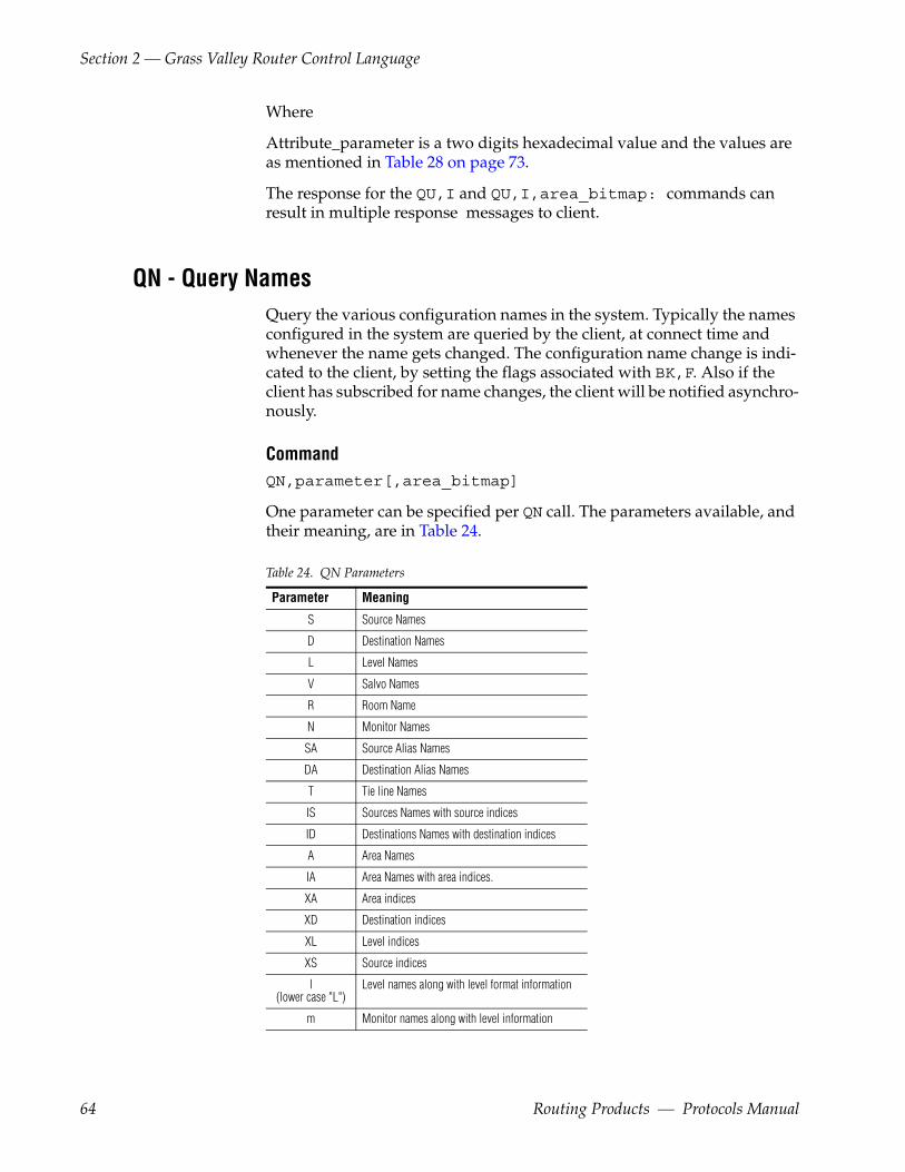
Section 2 — Grass Valley Router Control Language
Where
Attribute_parameter is a two digits hexadecimal value and the values are as mentioned in Table 28 on page 73.
The response for the QU,I and QU,I,area_bitmap: commands can result in multiple response messages to client.
QN - Query NamesQuery the various configuration names in the system. Typically the names configured in the system are queried by the client, at connect time and whenever the name gets changed. The configuration name change is indi-cated to the client, by setting the flags associated with BK,F. Also if the client has subscribed for name changes, the client will be notified asynchro-nously.
CommandQN,parameter[,area_bitmap]
One parameter can be specified per QN call. The parameters available, and their meaning, are in Table 24.
Table 24. QN Parameters
Parameter Meaning
S Source Names
D Destination Names
L Level Names
V Salvo Names
R Room Name
N Monitor Names
SA Source Alias Names
DA Destination Alias Names
T Tie line Names
IS Sources Names with source indices
ID Destinations Names with destination indices
A Area Names
IA Area Names with area indices.
XA Area indices
XD Destination indices
XL Level indices
XS Source indices
l(lower case "L")
Level names along with level format information
m Monitor names along with level information
64 Routing Products — Protocols Manual
Client Originated Message Descriptions
The optional area bitmap can be specified only for the parameters S/IS and D/ID. This area bitmap specifies the areas on which the client requests the names from the server. When the area bitmap parameter is not specified the source or destination names will be returned from all the areas that are present in the network. In case of large systems the number of areas may be significant and the client may be operating only on one or couple of areas. The area bitmap will specify the areas from where the names should be retrieved and returned to the client.
Response SNQ,S,nbr_sources[,src_name_entry1,...,src_name_entryn]
src_name_entryn is defined as:
fullqual_src_name,<‘N’|’T’>,level_bitmap
<‘N’|’T’> Indicates No-TieLine or Tieline related
Response DNQ,D,nbr_destns [,dest_name_entry1,...,dest_name_entryn]
dest_name_entryn is defined as:
fullqual_dest_name,<‘N’|’T’>,level_bitmap
<‘N’|’T’> Indicates No-TieLine or Tieline related
Response LNQ,L,nbr_levels[,lvl_name_entry1,...,lvl_name_entryn]
lvl_name_entryn is defined as:
lvl_name,lvl_number,< ‘R’ | ‘N’ >
lvl_number A hex ASCII number from 00 to 1f (representing levels 00 to 31 decimal)
‘R’ | ‘N’ Indicates that the level is Restricted or Not Restricted with respect to assignments
Response VNQ,V,nbr_salvos[,salvo_name1,...,salvo_namen]
Routing Products — Protocols Manual 65

Section 2 — Grass Valley Router Control Language
Response ISNQ,IS,nbr_sources [,IS_src_name_entry1,...,IS_src_name_entryn]
IS_src_name_entryn is defined as:
fullqual_src_name,fullqual_src_index,<‘N’|‘T’>, level_bitmap
<‘N’|’T’> No-tieline or Tieline Related
Response IDNQ,ID,nbr_destns [,ID_dest_name_entry1,..., ID_dest_name_entryn]
ID_dest_name_entryn is defined as:
fullqual_dest_name,fullqual_dest_index,<‘N’|‘T’>, level_bitmap
<‘N’|’T’> No-tieline or Tieline Related
Response ANQ,A,nbr_areas[,area_name1,...,area_namen]
Response IANQ,IA,nbr_areas [,area_name_entry1,...,area_name_entryn]
area_name_entryn is defined as:
area_name, area_index
CommandQN, R,[room name]
This command shall return the list of available room names along with room type. When the room_name is specified, this command shall return the details only for the specific room.
Response RNQ,R,nbr_rooms[,room_name_entry1,…room_name_entryN]
Where:
nbr_rooms: The number of rooms configured.
66 Routing Products — Protocols Manual

Client Originated Message Descriptions
room_name_entry is defined as room_name,room_index,room_type.
room_type can be S/C/A. Where S - Studio, C - Cubicle, A - standalone.
CommandQN,N
This command shall return the list of monitor names.
Response NNQ,N,nbr_monitors[,fullqual_mon_name1, …fullqual_mon_nameN]
Where:
nbr_monitors: The number of monitors configured.
fullqual_mon_name: The Name of the configured monitor. The fullqual_mon_name will be of the form area_name:monitor_name.
Example: A monitor named Mon1 in area NewsRm will be returned as NewsRm:Mon1.
Command QN,T[,tieline_name]
This command shall return the list of available tie line names along with type. When the tieline_name is specified, this command shall return the details only for the requested tie line as specified by the tieline_name.
Response NQ,T,nbr_tielines[,tie_line_name_entry1, …tie_line_name_entryN]
nbr_tielines: The number of tie lines configured in the system.
tie_line_name_entry is defined as tie_line_name, tie_line_type, tie_line_parameter
tie_line_type: can be F/R/X/A/M/U. Where F - Floating, R - Reserved, X - Fixed, A - Assignable, M-Room, U-Undefined
Routing Products — Protocols Manual 67

Section 2 — Grass Valley Router Control Language
Depending on the tie line type the tie_line_parameter can be one of the fol-lowing
Table 25.
Tie Line Type Tile Line Parameter
Reserved(R) Fully qualified destination name
Fixed(X) Fully qualified source name
Room(M) Room name
Floating(F),Assign-able(A),Undefined(U)
Blank
Command QN,SA
This query shall return source alias names.
Response SANQ,SA,nbr_sources[,SA_src_alias_name_entry1,…, SA_src_alias_name_entryN]
SA_src_alias_name_entry is defined as
fullqual_src_name,fullqual_src_index,TieLine_Type, Level_Bitmap ,fullqual_src_alias
Command QN,DA
This query shall return destination alias names.
Response DANQ,DA,nbr_destns[,DA_dest_alias_name_entry1,…, DA_dest_alias_name_entryN]
DA_dest_alias_name_entry is defined as:
fullqual_dest_name,fullqual_dest_index,TieLine_Type, Level_Bitmap,fullqual_dest_alias
For all responses <seq_flag=’0000’> for the last sequence sent.
Example
Suppose a client is interested in areas NEWSROOM and INGEST. The area index of NEWSROOM is 22 and that of INGEST is 2.
To query the source names (with indices) in the above areas the client needs to issue following command:
QN,IS,0000000000400004
68 Routing Products — Protocols Manual

Client Originated Message Descriptions
To query the destinations in all the areas the client can issue the command:
QN,D
Response XANQ, XA, No_entries, areaIndex1,…,areaIndexN
No_entries The numbers of available areas count.
Response XDNQ, XD, No_entries, dest_index_entry1… dest_index_entryN
No_entries: The numbers of available destinations count.
Dest_index_entry
fquall_dest_index, Tie_flag, dest_levelbitmap
Response XS NQ, XS, No_entries, src_index_entry1….,src_index_entryN
No_entries The numbers of available sources count.
src_index_ entry
fquall_src_index,Tie_flag, src_levelbitmap
Response XLNQ, XL, No_entries, levelIndex1,…,levelIndexN
No_entries The numbers of available level.
Response I (small "L")NQ,l,Number_of_entries, level_name_entry1,…,level_name_entryN.
Number_of_entries the number of levels in the system.
Level_name_entry defined as: level_name,level_index,level_medium_type,level_format_type
Routing Products — Protocols Manual 69

Section 2 — Grass Valley Router Control Language
Response m NQ,m,nbr_monitors[,Mon_name_Entry1,… Mon_name_EntryN],
Nbr_monitors The number of monitors present in system.
Mon_name_Entry Defined as: fquall_monitor_name, fquall_monitor_index,level_bitmap.
QV - Query Salvo ElementsQuery the salvo elements which make up the salvo. The salvo is specified by name.
CommandQV,salvo_name
Level_medium_type A 4 digital hexadecimal value.
Level_format_type A single character value. These variables can have values shown in Table 26.
Table 26. Level Format Type
Level Format NameLevel Medium
Type Value (Hexadecimal)
Level Format Type
Digital Video 0001 D
Digital Audio 0004 G
Analog Audio Stereo 0004 S
Analog Audio Left 0002 A
Analog Audio Right 0002 B
Composite 0001 V
Component 0001 C
Timecode 0008 T
Data 0010 R
Assignable Data 0040 N
Embedded data (Video+Audio) 0005 E
Multi Data 0080 M
Unknown 0000 ?
Any 0020 *
Others 0020 O
70 Routing Products — Protocols Manual

Client Originated Message Descriptions
ResponseVQ,salvo_name,nbr_entries[,entry1,...,entryn]
(<seq_flag=’0000’> for the last sequence sent.)
entryn is defined as follows:
fullqual_dest_name, fullqual_src_name,level_bitmap
Example
To query the salvo elements that comprise a salvo named RCLSVO1 the client needs to send
QV,RCLSVO1
QX- Query Cached Destination Status by IndexThe Clients communicating to a Redundant Encore system can send a QX command to query the cached destination status changes by index that was stored during the redundancy switchover. By sending this request the clients can obtain the cached destination status by index for a specified window of time during which the switch over happened instead of que-rying all the destination status (using QJ) which is time and network inten-sive. The cached destination status is stored in Encore for 20 seconds assuming that the client connects to the mirroring partner with in that duration.
Response
Response token will be XQ and the rest of the packet structure shall remain the same as for the existing RCL response JQ
QY - Query Cached Destination Status The Clients communicating to a Redundant Encore system can send a QY command to query the cached destination status changes that were stored during the redundancy switchover. By sending this request clients can obtain the cached destination status for a specified window of time during which the switch over happened instead of querying all the destination status (using QD) which is time and network intensive. The cached desti-nation status is stored in Encore for 20 seconds assuming that the client con-nects to the mirror pair with in that duration.
Response
Response token will be YQ and the rest of the packet structure shall remain the same as for the existing RCL response DQ
Routing Products — Protocols Manual 71

Section 2 — Grass Valley Router Control Language
RC - RCL ConnectRequest RCL connect to the RCL server.
CommandRC
The RCL server on getting a RC request from a client will check the validity of the client and accept the client request. A unique session_id is generated for the connection. Then the server responds back intimating the connec-tion acceptance by sending the following response.
ResponseRA, session_id
session_id The unique session_id created for this connection by the server. 2 Hex digits with values from 0-0xFF.
If the client reissues a RC, the session will be reinitialized. All the subscrip-tions made so far and the state information will be lost.If the client is not configured in the user interface, the connection will be closed without any response.
RD - RCL DisconnectRequest RCL disconnect.
CommandRD
Response
This will get an ER,00 response on success and an ER,nn (nn>0) on failure indicating the reason of failure.
This specifies the RCL disconnect request for the current session. Either the client or the server can send this. The end that receives disconnect request will respond back with an ER, 00 and terminate the session. The client will send this when it wants to close the session. For graceful disconnect the client should send RD before closing the socket or serial port.
72 Routing Products — Protocols Manual
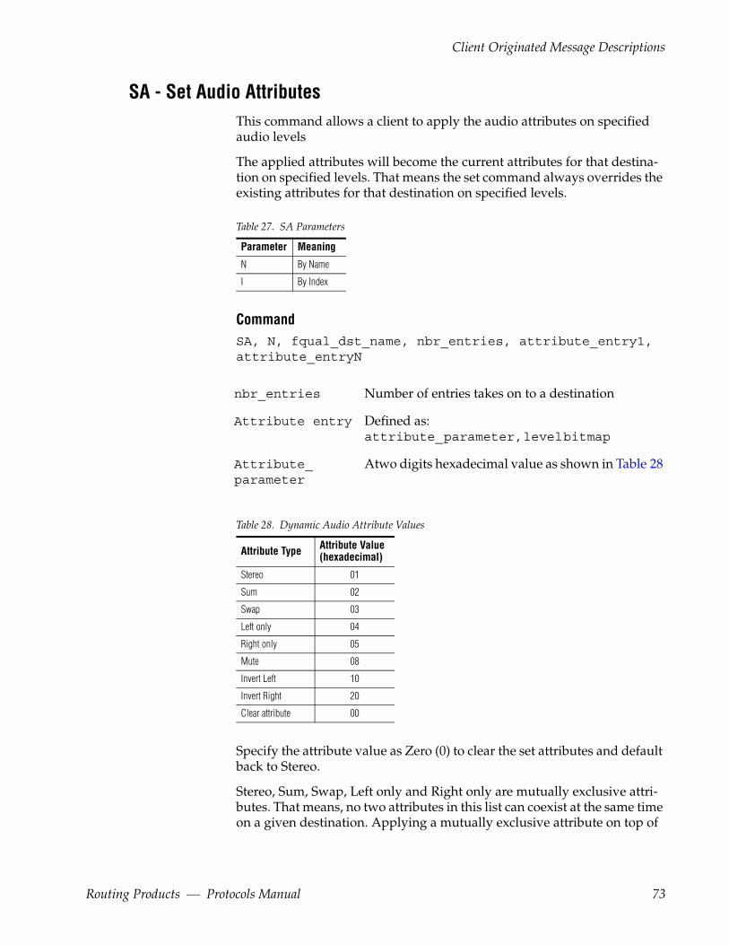
Client Originated Message Descriptions
SA - Set Audio Attributes This command allows a client to apply the audio attributes on specified audio levels
The applied attributes will become the current attributes for that destina-tion on specified levels. That means the set command always overrides the existing attributes for that destination on specified levels.
Table 27. SA Parameters
Parameter Meaning
N By Name
I By Index
CommandSA, N, fqual_dst_name, nbr_entries, attribute_entry1, attribute_entryN
nbr_entries Number of entries takes on to a destination
Attribute entry Defined as: attribute_ parameter, level bitmap
Attribute_ parameter
Atwo digits hexadecimal value as shown in Table 28
Table 28. Dynamic Audio Attribute Values
Attribute Type Attribute Value(hexadecimal)
Stereo 01
Sum 02
Swap 03
Left only 04
Right only 05
Mute 08
Invert Left 10
Invert Right 20
Clear attribute 00
Specify the attribute value as Zero (0) to clear the set attributes and default back to Stereo.
Stereo, Sum, Swap, Left only and Right only are mutually exclusive attri-butes. That means, no two attributes in this list can coexist at the same time on a given destination. Applying a mutually exclusive attribute on top of
Routing Products — Protocols Manual 73
Section 2 — Grass Valley Router Control Language
an existing mutually exclusive attribute will remove the previous attribute and retain only the current one.
Mute, Invert left, Invert Right are non-mutually exclusive attributes. That means, the attributes in this list can coexist at the same time on a given des-tination.
A given destination can have one mutually exclusive attribute and up to three non-mutually exclusive attributes at the same time.
The attribute parameter is used by the set attribute, get attribute and attri-bute change notification commands. This parameter will be referred as 'attribute_parameter' henceforth.
Response
This command will get an ER,00 response on success and an ER,nn (nn>0) on failure indicating the reason of failure.
Example
To apply the attributes "Swap" ,"Invert Left" and "Mute" on the destination DST1 in area INGEST on the level indices 2, 3 and 4 the following syntax can be used:
SA,N, INGEST:DST1,01,1b,0000000e
Here the attribute parameter is 0x1b ( 3(swap)+8(mute)+16(invert left) = 27 = 0x1b)
Command
SA,I, fqual_dst_index, nbr_entries ,attribute_entry1,… attribute_entryN
nbr_entries Number of entries takes on to a destination.
Attribute entry
defined as: attribute_parameter, level bitmap
Response
This command will get an ER,00 response on success and an ER,nn (nn>0) on failure indicating the reason of failure.
Example
To apply the attributes "Sum" ,"Invert Left" and "Invert Right " on the des-tination index 0x0000 (DST1) in area index 2 (INGEST) on the level indices 2, 3 and 6, the following syntax can be used:
SA,N, 01:0000,01,32,00000026
74 Routing Products — Protocols Manual

Client Originated Message Descriptions
Here the attribute parameter is 0x32 (2(sum) + 16(invert left) + 32(invert right) = 50 = 0x32).
TA – Take (Breakaway)Take the sources on the specified levels to the destination by name. TA facil-itates performing breakaway takes in a single request by name. The client can specify individual sources along with the levelbitmap information to take different sources on different levels. VITC time stamp can also be pro-vided to perform deterministic switching.
CommandTA,time_stamp,fullqual_dest_name,nbr_sources, src_name_entry1[,..., src_name_entryn]
(<seq_flag=’0000’> for the last sequence sent.)
time_stamp Time at which the take will be performed.
fullqual_dest_name Destination to be taken to.
nbr_sources Number of following entries (must be at least one).
src_name_entry is defined as:
fullqual_src_name,level_bitmap
Response
This will get an ER,00 response on success and an ER,nn (nn>0) on failure indicating the reason of failure.
Example
The example shows how to perform a breakaway take of the following sources on the levels specified to destination MON1 in area MIXROOM.
Source - MAINCAM Level index – 3
Source - ANCCAM Level index - 2
Source – FEED Level index – 1
All the above sources are in area MIXROOM.
TA,, MIXROOM:MON1,3, MIXROOM:MAINCAM,00000008, MIXROOM:ANCCAM,00000004, MIXROOM:FEED,00000002
Routing Products — Protocols Manual 75
Section 2 — Grass Valley Router Control Language
The above take was non time stamped and thus the timestamp field is blank. However the separator needs to be sent as part of the message.
Note Separators are horizontal tabs ([HT]) represented by the comma (,) char-acter. In the example, the comma after the TA, represents the horizontal tab for the blank time_stamp field. For more information on notation see Command and Message Description Notation on page 18.
TD - Take (Single Source)Take the source on the specified levels to the destination by name. The level information can be omitted from this command thus allowing to perform an All Level take. VITC time stamp can also be provided to perform deter-ministic switching.
CommandTD,time_stamp, fullqual_dest_name,src_name_entry
time_stamp Time at which the take will be performed.
fullqual_dest_name Destination to be taken to
src_name_entry is defined as:
fullqual_src_name[,levelbitmap]
With no level bitmap specified, the source will be taken to all levels of the destination.
Response
This will get an ER,00 response on success and an ER,nn (nn>0) on failure indicating the reason of failure.
Example
To take the sources FEED1 in area INGEST on the level indices 2,3and 4 to the destination VW3 in area POSTPROD the following syntax is used:
TD,,POSTPROD:VW3,INGEST:FEED1,0000001C
The above take will need a tie-line to have been defined in the system between areas INGEST and POSTPROD.
76 Routing Products — Protocols Manual

Client Originated Message Descriptions
TI - Take by Level IndexTake the source on the specified levels to the destination by index. The level information can be omitted from this command thus allowing to perform an all level Take. VITC time stamp can also be provided to perform deter-ministic switching. In this command the source, destination and level should be specified using their indexes.
CommandTI,time_stamp, fullqual_destIndex, fullqual_srcIndex [,levelIndex]
time_stamp Time at which the take will be performed.
All indexes (dstIndex, lvlIndex, srcIndex) are zero–based hex. These indexes refer to the logical index for each entity, not to the physical port number. However, the system can be configured so that port numbers are identical to index numbers. There is no disconnect index number, all indexes refer to configured entities. Valid indexes and their association with specific names can be determined by using the commands: QN, L; QN, ID; QN, IS.
Response
This will get an ER,00 response on success and an ER,nn (nn>0) on failure indicating the reason of failure.
Example
To take the source FEED1 with index 3 in area INGEST whose index is 5 on all levels to the destination VW3 (index 1) in the same area the following syntax is used:
TI,,05:0001,05:0003
TJ - Take by Level BitmapTake the sources on the specified levels to the destination by index. TJ facil-itates performing breakaway takes in a single request by index. The client can specify individual sources along with the levelbitmap information to take different sources on different levels. VITC time stamp can also be pro-vided to perform deterministic switching.
CommandTJ,time_stamp, fullqual_dest_index,nbr_sources, src_name_entry1[,..., src_name_entryn]
Routing Products — Protocols Manual 77

Section 2 — Grass Valley Router Control Language
(<seq_flag=’0000’> for the last sequence sent.)
time_stamp Time at which the take will be performed.
fullqual_dest_index Destination to be taken to
nbr_sources Number of following entries (must be at least one)
src_name_entryn is defined as:
fullqual_src_index,level_bitmap
All indexes (dstIndex, lvlIndex, srcIndex) are zero–based hex num-bers. These indexes refer to the logical index for each entity, not to the phys-ical port number. However, the system can be configured so that port numbers are identical to index numbers. There is no disconnect index number. All indexes refer to configured entities. Valid indexes and their association with specific names can be determined by using the commands: QN, L; QN, ID; QN, IS.
Response
This will get an ER,00 response on success and an ER,nn (nn>0) on failure indicating the reason of failure.
Example
To perform a timed take at 16 hours, 23 minutes, 10 seconds and 15 th frame of the source FEED1(index 3) in area INGEST (index 5) on the levels 0 and 1 to the destination VW3 (index 1) in the same area the following syntax is used:
TJ,16231015,1,05:0001,05:0003,00000003
TM - Take MonitorTake the source or destination as specified by mon_type to monitor on specified levels.
The level bitmap is an optional parameter which if not specified results in an all level monitor take.
78 Routing Products — Protocols Manual

Client Originated Message Descriptions
CommandTM, fullqual_type_name[,mon_type, fullqual_mon_name[,level bitmap] ]
Fullqual_type_name
Defined as: fullyqual_src_name or fullqual_dst_name
mon_type 'S' is Source, 'D' is Destination
Fullqual_mon_name
Configured monitor name or default monitor name.
Response
The Command will get an ER,00 response on success and an ER,nn (nn>0) on failure indicating the reason of failure.
Example
To take the destination DST1 in area INGEST on 3rd and 5th levels of monitor MON1 (same area) the following syntax is used:
TM,INGEST:DST1,D,INGEST:MON1,00000014
TS - Take SalvoExecute the salvo specified by the salvo_name. VITC time stamp can also be provided to perform deterministic switching.
CommandTS,time_stamp,salvo_name
time_stamp Time at which the take will be performed.
salvo_name Salvo name
Response
This will get an ER,00 response on success and an ER,nn (nn>0) on failure indicating the reason of failure.
Example
To perform a Salvo take of a salvo name RCLSVO1 the following command syntax should be used:
Routing Products — Protocols Manual 79

Section 2 — Grass Valley Router Control Language
TS,,RCLSVO1
10.Add the UI command description after "TS- Take Salvo " description in protocol manual (on page number 65 of revision number 071-0201-07.pdf)
UI - Unprotect by IndexUnprotect command allows the protect on the specified destination to be removed on the specified level. The levelbitmap is an optional parameter which if not provided will result in an unprotect on all levels.
CommandUI,fullqual_dest_index[,level_bitmap]
Response
This command will get an ER,00 response on success and an ER,nn (nn>0) on failure indicating the reason of failure.
UP - Request UnprotectUnprotect command allows the protect on the specified destination to be removed on the specified level. The command requires a level_bitmap to be specified on which unprotect should be performed. The format of the Unprotect command is shown below.
CommandUP,fullqual_dest_name,level_bitmap
Response
This will get an ER,00 response on success and an ER,nn (nn>0) on failure indicating the reason of failure.
Example
To Unprotect a destination named PDR2 in area POSTPRD on levels with indices 3 and 4 the client should issue the following command:
UP,POSTPRD:PDR2,00000018
80 Routing Products — Protocols Manual

Client Subscription Message Descriptions
Client Subscription Message Descriptions
SB – SubscribeSubscribe request for status/configuration change information. The spe-cific information for which the client subscribes is decided based on the subscription type and parameters sent as part of the SB command.
CommandSB[, subscription_type[,parameters]]
The subscription type specifies the status or particular configuration ele-ment. Refer to Table 29 for the list of available subscription type acronyms. If no subscription type is specified in the SB command, then a global sub-scription for all supported events is done. The parameters for any subscrip-tion command depend on the subscription type and are explained in the Subscription Commands Usage on page 83.
Note Using the SB command without any parameters is not recommended. Instead, use the "SB,SL" or "SB,SL,D" commands. Without parameters, more than one delete notification will be received by the RCL client. Though this should not cause problems, it may lead to additional processing by the client.
Response
Subscription request will get an ER,00 response on success and an ER,nn (nn>0) on failure indicating the reason of failure.
UB – Unsubscribe Request Unsubscribe request for already subscribed status/configuration change information. The specific information for which the client un-subscribes is decided based on the subscription type and parameters sent as part of the UB command.
CommandUB[, subscription_type[,parameters]]
The subscription type specifies the status or particular configuration ele-ment. Refer to Table 29 for the list of available subscription type acronyms. If no subscription type is specified in the UB command, then a global un-subscription for all subscribed events is done. The parameters for any unsubscribe command depend on the subscription type that needs to be unsubscribed and are explained in the Subscription Commands Usage on page 83.
Routing Products — Protocols Manual 81
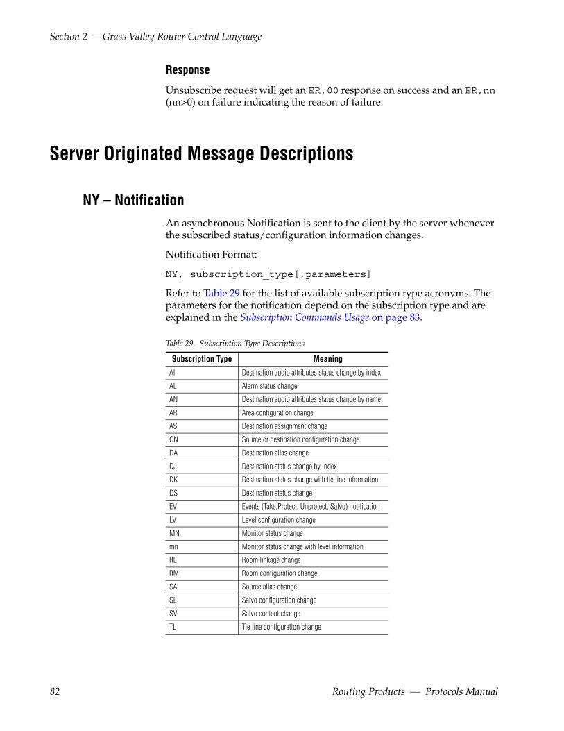
Section 2 — Grass Valley Router Control Language
Response
Unsubscribe request will get an ER,00 response on success and an ER,nn (nn>0) on failure indicating the reason of failure.
Server Originated Message Descriptions
NY – NotificationAn asynchronous Notification is sent to the client by the server whenever the subscribed status/configuration information changes.
Notification Format:
NY, subscription_type[,parameters]
Refer to Table 29 for the list of available subscription type acronyms. The parameters for the notification depend on the subscription type and are explained in the Subscription Commands Usage on page 83.
Table 29. Subscription Type Descriptions
Subscription Type Meaning
AI Destination audio attributes status change by index
AL Alarm status change
AN Destination audio attributes status change by name
AR Area configuration change
AS Destination assignment change
CN Source or destination configuration change
DA Destination alias change
DJ Destination status change by index
DK Destination status change with tie line information
DS Destination status change
EV Events (Take,Protect, Unprotect, Salvo) notification
LV Level configuration change
MN Monitor status change
mn Monitor status change with level information
RL Room linkage change
RM Room configuration change
SA Source alias change
SL Salvo configuration change
SV Salvo content change
TL Tie line configuration change
82 Routing Products — Protocols Manual

Subscription Commands Usage
RD - RCL DisconnectRequest RCL disconnect.
CommandRD
Response
This will get an ER,00 response on success and an ER,nn (nn>0) on failure indicating the reason of failure.
This specifies the RCL disconnect request for the current session. Either the client or the server can send this. The end that receives disconnect request will respond back with an ER, 00 and terminate the session. The client will send this when it wants to close the session. For graceful disconnect the client should send RD before closing the socket or serial port.
RN - RCL AnnounceThe RCL server during start up will send a command called RCL Announce (RN) to all the connected clients indicating that the server has just started up.
CommandRN
Response
None
Subscription Commands UsageThis section describes the usage of the subscribe (SB),unsubscribe (UB) and the notification (NY) commands. These commands are described with respect to the following types of subscription
• Status Change Subscriptions on page 84
• Configuration Change Subscriptions on page 88
Routing Products — Protocols Manual 83
Section 2 — Grass Valley Router Control Language
Status Change SubscriptionsA RCL client can subscribe for destination status of one or a group of des-tinations. Whenever the status of a destination changes, all the clients that have subscribed for that destination status receive a notification.
Subscribe for Status Change
Subscribe command for destination status could be used in the following formats.
CommandSB, DS
The client receives notifications, whenever the status of any destination in any area changes.
CommandSB, DS, area index
The client receives notifications, whenever the status of any destination in the area specified by the area index changes.
Example
To subscribe for destination status changes in area POSTPRD (index 2) the client should issue the following command: SB,DS,02.
SB, DS, fullqual_dest_name
The client receives notification only if the status of the specified destination changes.
Unsubscribe for Status Change
Unsubscribe command for destination status could be used in the fol-lowing formats.
CommandUB, DS
Unsubscribe destination status change notifications for all destinations in all areas
CommandUB, DS, area index
Unsubscribe destination status change notifications in the area specified by the area index
84 Routing Products — Protocols Manual
Subscription Commands Usage
CommandUB, DS, fullqual_dest_name
Unsubscribe the specified destination change notification.
Example
To unsubscribe for destination status changes for destination VW3 in area POSTPRD, the client should issue the following command: UB,DS,POSTPRD:VW3
Illegal Subscribe and Unsubscribe Combinations
Do not use these subscribe and unsubscribe combinations:
SB,DS and UB,DS, fullqual_dest_name orSB,DS, area bitmap and UB,DS, fullqual_dest_name
In these cases an appropriate error will be sent back to the client.
Notification for Status Change
Whenever the status for a destination changes, all RCL clients that have subscribed for that destination’s status receive notifications in the fol-lowing format.
NY, DS, fullqual_dest_name, nbr_sources [,src_name_entry1,..., src_name_entryn]
src_name_entryN is defined as
<‘N’|’P’>,<‘N’|’C’>, fullqual_src_name,level_bitmap, [prot_device_name], [fullqual_chopsrc_name]
The fully qualified chop source name will be returned as "Chopping".
Note The notification format is similar to the DQ response.
Destination Status Change By Index A RCL client can subscribe for destination status change of one or a group of destinations. Whenever the status of destination changes, all the clients that have subscribed for that destination status change receives a notifica-tion.
Subscribe for Status Change
Subscribe command for destination status change can be used in the fol-lowing formats.
Routing Products — Protocols Manual 85

Section 2 — Grass Valley Router Control Language
CommandSB, DJ
The client receives notifications, whenever the status of any destination changes.
Command SB,DJ,area_index:
The client receives notifications, whenever the destination status of any destination in the area specified by the area index changes.
Specifying a colon ':' after the area index is necessary.
CommandSB, DJ, fullqual_dest_Index
The client receives notification, whenever the destination status is changed for specified destination index.
Command SB, DJ, Destination Range
Destination Range
Defined as: fullqual_dest_index1, fullqual_dest_indexN
The client will receive a notification, when the status is changed for any of the the destinations in the range of the fully qualified destination index 1 and fully qualified destination index N. The range must be from a single area and cannot span multiple areas. In addition, the range has to be in the ascending order of indices.
Response
This commands will get an ER,00 response on success and an ER,nn (nn>0) on failure indicating the reason of failure.
Example
To subscribe for destination status change for destinations "0000" to "0008" in area index 0x02, the client should issue the following command
SB, DJ, 02:0000, 02:0008
The client receives notification, whenever the destination status is changed for the destination indices 0000, 0001, 0002,0003,0004,0005,0006,0007,0008
86 Routing Products — Protocols Manual

Subscription Commands Usage
Notification for Destination Status Change
Whenever the destination status is changed all RCL clients that have sub-scribed for the same will receive notifications in the following format.
NY, DJ, fullqual_dest_index, nbr_sources, src_name_entry1….src_name_entryN.
Nbr_sources Number of sources on that destination which are being reported in this message sequence.
Src_name_entry is defined as”
<'N'/'P'>,<'N'/'C'>, fullqual_src_index,level_bitmap, [protect_device_name], [fullqual_chop_src_index]
The fully qualified chop source index will be returned as "0xFFFA".
This notification is similar to QJ response.
Unsubscribe for Status Change
Unsubscribe command for destination status change notifications can be used in the following formats.
CommandUB, DJ
Unsubscribe for destination status change notifications for all destinations.
CommandUB,DJ,area_index:
Unsubscribe for destination status change notifications for all destinations in the area specified by the area index.
A colon ":" at the end of the command is necessary.
CommandUB, DJ, fullqual_dest_index
Unsubscribe for status change notifications only for the specified destina-tion.
Command UB, DJ, fullqual_dest_index1, fullqual_dest_indexN
Routing Products — Protocols Manual 87

Section 2 — Grass Valley Router Control Language
Unsubscribe for status change notifications for the specified destination range.
Response
This command will get an ER,00 response on success and an ER,nn (nn>0) on failure indicating the reason of failure.
Example
To unsubscribe for status change notification for a destination range "0000" to "0008" on area index 0x02, the following command can be used:
UB, DJ, 02:0000,02:0008
Configuration Change SubscriptionsA RCL client can subscribe for changes in the configuration of the system. The configuration changes that can be subscribed for are described along with their command format in this section.
Subscribe for Configuration Change
Subscribe command for Configuration change could be used in the fol-lowing formats.
CommandSB, CN [, area index]
Subscribe to get notified, when destination or source configuration changes in the router. When the optional area index is specified, the server will send notification for changes only in the specified area.
CommandSB, LV
Subscribe to get notified, when level configuration changes.
CommandSB, SL
Subscribe for salvo configuration changes.
CommandSB, AR
Subscribe for area configuration changes.
88 Routing Products — Protocols Manual
Subscription Commands Usage
CommandSB, SV
Subscribe for content changes of any salvo.
Example
To Subscribe for source and destination configuration changes in areas POSTPRD (index 4) and EDITROOM (index 2), the client should issue the following commands:
SB,CN,04SB,CN,02
Unsubscribe for Configuration Change
The previously subscribed configuration change subscriptions can be unsubscribed using the Unsubscribe command syntaxes shown below.
CommandUB, CN [, area index]
Unsubscribe the source and destination configuration change subscription. The client can choose to unsubscribe only in specific area by specifying the area index.
CommandUB, LV
Unsubscribe level configuration change subscription.
CommandUB, SL
Unsubscribe salvo configuration change subscription.
CommandUB, AR
Unsubscribe area configuration change subscription.
CommandSB, SV
Unsubscribe the previously subscribed salvo content change subscription.
Routing Products — Protocols Manual 89
Section 2 — Grass Valley Router Control Language
Notification for Configuration Change
Whenever a configuration change occurs in the system, all the RCL clients that have subscribed for that configuration change receive a notification from the RCL server with the subscription type specifying the element which has changed. In case of source and destination name changes, the clients also receive additional area bitmaps specifying the areas in which the names have changed.
NY, subscription_type [, area index]
subscription_type One of the subscription types specified in Table 29 (Except DS and SV).
Area index Specified only if the subscription type is CN. The area index indicates the area on which the desti-nation or source configuration has changed.
Upon receiving this notification, the client has to invoke specific commands to refresh the changed configuration.
Example
If the client receives a notification with the subscription_type as SL, then the client should issue a QN, V to reload the fresh salvo names from the system.
In case of salvo content change subscriptions, whenever the content of a salvo changes, the following notification is sent to all clients that have sub-scribed for that change.
CommandNY, SV, salvo name
When a client receives such a notification, the client has to send a salvo status query (QV) for the notified salvos to refresh their contents.
Assignment Change SubscriptionA RCL client can subscribe for assignment changes of one or a group of des-tinations. When the assignments are changed in the system all the sub-scribed clients receive notification about the assignment change.
Subscribe for Assignment Status Change
Subscribe for assignment status change can be used in the following for-mats.
90 Routing Products — Protocols Manual
Subscription Commands Usage
CommandSB,AS
The client receives notifications, whenever the assignment status of any destination in any area changes.
CommandSB,AS,area index
The client receives notifications, whenever the assignment status of any destination in the area specified by the area index changes.
CommandSB,AS,fullqual_dest_name
The client receives notifications, whenever the assignment status of the destination represented by fullqual_dest_name changes.
Example
To subscribe for assignment status changes (by index) in area POSTPRD (index 2) the client should issue the following command:
SB,AS,02
Response
The SB,AS command will get an ER,00 response on success and an ER,nn(nn>0) on failure indicating the reason of failure.
Notification for Assignment Change
Whenever the assignments for a destination changed, all RCL clients that have subscribed for the same receive notifications in the following format.
NY,AS,fullqual_dest_name,nbr_sources[,fullqual_src_name1…fullqual_src_nameN]
Unsubscribe Assignment Status change
The Unsubscribe Assignment status change command can be used in the following formats.
CommandUB,AS
Unsubscribe assignment status change notifications for all destinations in all areas
Routing Products — Protocols Manual 91
Section 2 — Grass Valley Router Control Language
CommandUB,AS,area index
Unsubscribe assignment status change notifications in the area specified by the area index
CommandUB,AS,fullqual_dest_name
Unsubscribe the assignment change notification for destination specified by fullqual_dest_name.
Example
To unsubscribe the assignment status changes for destination VTR1 in area POSTPRD, the client should issue the following command:
UB,AS,POSTPRD:VTR1
Response
The UB,AS Command will get an ER,00 response on success and an ER,nn (nn>0) on failure indicating the reason of failure.
Destination Status Change Subscription (by Index w/ Tie-line Info)A RCL client can subscribe for destination status change by index along with tie line information for one or a group of destinations. This lets the client know of changes in tie line usage as well. When the destination status changes for a subscribed destination, the RCL Server shall notifies the sub-scribed clients with the information on the latest status for that destination.
Subscribe for Destination Status Change (By Index w/ Tie-line Info)
Subscribe for destination status change (By Index w/ Tie-line Info) can be used in the following formats.
CommandSB,DK
The client receives notifications, whenever the status of any destination in any area changes along with the tie line information.
CommandSB,DK,area index
92 Routing Products — Protocols Manual
Subscription Commands Usage
The client receives notifications, whenever the status of any destination in the area specified by the area index changes along with the tie line informa-tion.
CommandSB,DK,fullqual_dest_name
The client receives notifications, whenever the status of the destination rep-resented by fullqual_dest_name changes along with the tie line informa-tion.
Response
The SB,DK Command will get an ER,00 response on success and an ER,nn(nn>0) on failure indicating the reason of failure.
Notification for Destination Status Change by Index w/ Tie-line Info
Whenever the destination status changes, all RCL clients that have sub-scribed for the same receive notifications in the following format.
NY,DK,fullqual_dest_index,nbr_sources[,lsrc_index_entry1…,src_index_entryN]
src_index_entryn is defined as:
<'N'|'P'>,<'N'|'C'>,nbr_tielines,fullqual_src_index, level_bitmap,[device_name],[fullqual_chop_src_index] [,tie_line_name1…,tie_line_nameN]
Whenever the destination status changes, all RCL clients that have sub-scribed for the same receive notifications in the following format.
NY,DK,fullqual_dest_index,nbr_sources [,lsrc_index_entry1…,src_index_entryN]
src_index_entryn is defined as:
<'N'|'P'>,<'N'|'C'>,nbr_tielines,fullqual_src_index,level_bitmap, [device_name],[fullqual_chop_src_index][,tie_line_name1…, tie_line_nameN]
The source index contains specific values for the "Undef","No_xpt", "Parked" and "No_Mtrx" Refer the table Table 19 on page 57.
The fully qualified chop source index will be returned as "0xFFFA".
Un-Subscribe Destination Status Change by Index w/ Tie-line Info
Unsubscribe for destination status change (By Index w/ Tie-line Info) can be used in the following formats.
Routing Products — Protocols Manual 93
Section 2 — Grass Valley Router Control Language
CommandUB,DK
Unsubscribe status change notifications by index along with the tie line information for all destinations in all areas.
CommandUB,DK,area index
Unsubscribe status change notifications by index along with the tie line information in the area specified by the area index.
CommandUB,DK,fullqual_dest_name
Unsubscribe the specific status change notification by index along with the tie line information for destination fullqual_dest_name.
Response
The UB,DK Command will get an ER,00 response on success and an ER,nn(nn>0) on failure indicating the reason of failure.
Monitor Status Change SubscriptionA RCL client can subscribe for monitor status change. Whenever the monitor status is changed all the clients that have subscribed for that receive a notification
Subscribe for Monitor Status Change
Subscribe for monitor status change notification can have the following formats
CommandSB,MN
The client receives notifications, whenever the status of any monitor in any area changes.
CommandSB,MN,area index
The client receives notifications, whenever the status of any monitor in the area specified by the area index changes.
94 Routing Products — Protocols Manual

Subscription Commands Usage
CommandSB,MN,fullqual_mon_name
The client receives notifications, whenever the status of the monitor repre-sented by fullqual_mon_name changes.
Example
To subscribe for monitor status changes in area POSTPRD (index 2) the client should issue the following command: SB,MN,02.
Response
SB,MN Command will get an ER,00 response on success and an ER,nn (nn>0) on failure indicating the reason of failure.
Notification for Monitor Status Change
Whenever the status for a monitor changed, all RCL clients that have sub-scribed for that monitor's status receives notifications in the following format.
NY,MN,fullqual_mon_name,mon_type,fullqual_type_name
Unsubscribe Monitor Status Change
Unsubscribe for monitor status change notification can have the following formats
CommandUB,MN
Unsubscribe monitor status change notifications for all monitors in all areas
CommandUB,MN,area index
Unsubscribe monitor status change notifications in the area specified by the area index
CommandUB,MN,fullqual_mon_name
Unsubscribe the specific monitor change notification for monitor with name fullqual_mon_name.
Routing Products — Protocols Manual 95
Section 2 — Grass Valley Router Control Language
Example
To unsubscribe the monitor status changes for monitor Mon3 in area POSTPRD, the client should issue the following command:
UB,MN,POSTPRD:Mon3
Response
UB,MN Command will get an ER,00 response on success and an ER,nn (nn>0) on failure indicating the reason of failure.
Monitor Status Change with Level InformationA RCL client can subscribe for monitor status change. Whenever the monitor status is changed all the clients that have subscribed for that receive a notification with level information.
Subscription for Monitor status Change with Levels
CommandSB,mn
The client receives notifications, whenever the status of any monitor in any area changes.
Response
This command will get an ER,00 response on success and an ER,nn (nn>0) on failure indicating the reason of failure.
Notification for Monitor Status Change
Whenever the any monitor status is changed, all RCL clients that have sub-scribed for it to be notified of the change and notification will be in the fol-lowing format.
NY,mn,fullqual_mon_name,mon_type,number_of_entries [,type_name_entry1… type_name_entryN
fullqual_mon_name configured monitor name.
mon_type 'S' is Source , 'D' is Destination.
number_of_entries Defined as the number of entries in response.
96 Routing Products — Protocols Manual

Subscription Commands Usage
type_name_entry is defined as:
fully_qualified_type_name,level_bitmap
fully_qualified_type_name a fullyqualified source/destination name based on the mon_type.
Unsubscription for Monitor Status Change
CommandUB,mn
Unsubscribe for monitor status change notification for all monitor.
Response
This command will get an ER,00 response on success and an ER,nn (nn>0) on failure indicating the reason of failure.
Tie-line Configuration Change SubscriptionA client can subscribe for tie line configuration changes. When the tie line configuration is changed in the system all the subscribed clients receive notification of the change.
Subscribe for Tie-line Configuration Change
Command SB,TL
Response
SBB,TL will get an ER,00 response on success and an ER,nn (nn>0) on failure indicating the reason of failure.
Notification for Tie-Line Configuration Change
RCL Server shall provide notification as described below when the Tie line configuration change occurs
NY,TM
Unsubscribe Tie-Line Configuration Changes
Unsubscribe for tie line configuration change notifications.
Routing Products — Protocols Manual 97
Section 2 — Grass Valley Router Control Language
Command UB,TL
Response
UB,TL will get an ER,00 response on success and an ER,nn (nn>0) on failure indicating the reason of failure.
Source Alias Change SubscriptionA RCL client can subscribe for source alias name change. Whenever the source alias name is changed all the clients that have subscribed for that alias change receive a notification.
Subscribe for Source Alias Change
Subscribe for source alias change notification can have the following for-mats.
CommandSB,SA
The client receives notifications, whenever any source alias in any area changes.
CommandSB,SA,area_index
The client receives notifications, whenever any source alias in the area spec-ified by the area index changes.
Example
To subscribe for source alias changes in area POSTPRD (index 2) the client should issue the following command: SB,SA,02.
Response
The SB,SA will get an ER,00 response on success and an ER,nn (nn>0) on failure indicating the reason of failure.
Notification for Source Alias Change
Whenever the source alias is changed, all RCL clients that have subscribed to be notified of the change shall receive notifications in the following
NY,SA,area_index
98 Routing Products — Protocols Manual

Subscription Commands Usage
area_index - Specifies the area (by index) where the source alias changes have been effected.
Unsubscribe Source Alias Change
Unsubscribe for source alias change notification can have the following for-mats.
CommandUB,SA
Unsubscribe alias change notification for all source alias in all areas.
CommandUB,SA,area_index
Unsubscribe alias change notifications for all source alias changes in the area specified by the area_index.
Example
To unsubscribe the notifications when the source alias changes for source alias change in area POSTPRD (index 03), the client should issue the fol-lowing command: UB,SA,03.
Response
The UB,SA Command will get an ER,00 response on success and an ER,nn(nn>0) on failure indicating the reason of failure.
Destination Alias Change SubscriptionA RCL client can subscribe for destination alias name change. Whenever the destination alias name is changed all the clients that have subscribed for that alias change receive a notification.
Subscribe for Destination Alias Change
Subscribe for destination alias change notification can have the following formats.
CommandSB,DA
The client receives notifications, whenever any destination alias in any area changes.
Routing Products — Protocols Manual 99

Section 2 — Grass Valley Router Control Language
CommandSB,DA,area_index
The client receives notifications, whenever any destination alias in the area specified by the area index changes.
Example
To subscribe for destination alias changes in area POSTPRD (index 2) the client should issue the following command: SB,DA,02.
Response
The SB,DA command will get an ER,00 response on success and an ER,nn (nn>0) on failure indicating the reason of failure.
Notification for Destination Alias Change
Whenever the destination alias is changed, all RCL clients that have sub-scribed to be notified of the change shall receive notifications in the fol-lowing
NY,DA,area_index
Where
area_index - Specifies the area (by index) where the destination alias changes have been effected.
Unsubscribe Destination Alias Change
Unsubscribe for destination alias change notification can have the fol-lowing formats.
CommandUB,DA
Unsubscribe alias change notification for all destination alias in all areas.
CommandUB,DA,area_index
Unsubscribe alias change notifications for all destination alias changes in the area specified by the area_index.
Example
To unsubscribe the notifications when the destination alias changes for des-tination alias change in area POSTPRD (index 03), the client should issue the following command: UB,DA,03.
100 Routing Products — Protocols Manual
Subscription Commands Usage
Response
The UB,DA Command will get an ER,00 response on success and an ER,nn(nn>0) on failure indicating the reason of failure.
Room Configuration Changes SubscriptionA RCL client can subscribe for room configuration changes. When the room configuration in the system is changed all the subscribed clients receive notification about the change.
Subscribe for Room Configuration Change
CommandSB,RM
Response
SB,RM will get an ER,00 response on success and an ER,nn (nn>0) on failure indicating the reason of failure.
Notification for Room Configuration Changes
Whenever the room configuration is changed all RCL clients that have sub-scribed for the same receive notifications in the following format.
NY,RM
Unsubscribe Room Configuration Changes
Unsubscribe for room configuration change notifications.
Command UB,RM
Response
UB,RM will get an ER,00 response on success and an ER,nn (nn>0) on failure indicating the reason of failure.
Room Linkage Changes SubscriptionA client can subscribe for room linkage changes. When the room linkage in the system is changed all the subscribed clients receive noti-fication about the change.
Routing Products — Protocols Manual 101
Section 2 — Grass Valley Router Control Language
Subscribe for Room Linkage Change
Command SB,RL.
Response
SB,RL will get an ER,00 response on success and an ER,nn (nn>0) on failure indicating the reason of failure.
Notification for Room Linkage Change
Whenever the room linkage changes all RCL clients that have subscribed for the same receive notifications in the following format.
NY,RL,stu_room_name,nbr_linked_cub_rooms [,cub_room_name1,…tcub_room_nameN]
Table 30. Parameter Descriptions
stu_room_name Name of the studio room whose linkage has changed.
nbr_cub_rooms Number of cubicle rooms linked to the studio room named stu_room_name.
cub_room_nameN Name of the N th cubicle room linked to studio.
Unsubscribe Room Linkage Changes
Unsubscribe for room linkage change notifications.
Command UB,RL
Response
UB,RL will get an ER,00 response on success and an ER,nn (nn>0) on failure indicating the reason of failure.
Attribute Status Change Subscription by IndexA RCL client can subscribe for attribute status change by index for one or a group of destinations. Whenever the destination attribute status changes, all the clients that have subscribed for this destination status receive a noti-fication.
102 Routing Products — Protocols Manual
Subscription Commands Usage
Subscribe for Attribute Status Change
Subscribe for destination attribute status change notification can have the following formats.
Command SB,AI
The client receives notifications, whenever any audio attribute changes for any destination.
Command SB,AI,area_index:
The client receives notifications, whenever any audio attribute changes for destination in the area specified by the area index changes.
A colon ":" at the end of the command is necessary.
Command SB,AI,fqual_dst_index
The client receives notifications, whenever any audio attribute changes for specified destination.
Response
These commands will get an ER,00 response on success and an ER,nn (nn>0) on failure indicating the reason of failure.
Example
To subscribe for audio attributes changes in area POSTPRD (index 2) the client should issue the following
SB,AI,02
Notification for Attribute Change by Index
Whenever the attributes changes for a destination, all RCL clients that have subscribed for that receive attribute change notification in the following format . The notification contains attributes status on all applicable levels.
NY,AI, fqual_dst_index, nbr_entries,attribute_entry1,.. attribute_entryN
nbr_entries Number of attribute parameters on this destination.
Attribute_entry Defined as: attribute_paramter, levelbitmap
Routing Products — Protocols Manual 103

Section 2 — Grass Valley Router Control Language
Unsubscribe for Attribute Status Change
Unsubscribe command for destination attribute change could be used in the following formats.
Command UB,AI
The client receives notifications, whenever any audio attribute changes for destinations in any area.
Command UB,AI,area_index:
The client receives notifications, whenever any audio attribute changes for destination in the area specified by the area index changes.
A colon ":" at the end of the command is necessary.
Command UB,AI,fqual_dst_index
The client receives notifications, whenever any audio attribute changes for specified destination.
Response
This commands will get an ER,00 response on success and an ER,nn (nn>0) on failure indicating the reason of failure.
Example
To subscribe for audio attributes changes in area POSTPRD (index 2) the client should issue the following command
UB,AI,02.
Attribute Status Change Subscription by NameA RCL client can subscribe for attribute status change by name for one or a group of destinations. Whenever the destination attribute status changes, all the clients that have subscribed for this destination status receive a noti-fication.
Subscribe for Attribute Status Change
The subscribe command for destination attribute status change has the fol-lowing formats.
104 Routing Products — Protocols Manual
Subscription Commands Usage
Command SB,AN
The client receives notifications, whenever audio attribute changes for any destination.
Command SB,AN,area_index:
The client receives notifications, whenever any audio attribute changes for destination in the area specified by the area index.
A colon ":" at the end of the command is necessary.
Command SB,AN,fqual_dst_name
The client receives notifications, whenever any audio attribute changes for specified destination.
Response
This commands will get an ER,00 response on success and an ER,nn (nn>0) on failure indicating the reason of failure.
Example
To subscribe for audio attributes changes in area POSTPRD (index 2) the client should issue the following command:
SB,AN,02
Notification for Attribute Change by Name
Whenever the attributes changes for a destination, all RCL clients that have subscribed for that receive attribute change notification in the following format. The notification contains attributes status on all applicable levels.
NY,AN, fqual_dst_name, nbr_entries,attribute_entry1,.. attribute_entryN
nbr_entries Number of attribute parameters on this destination.
Attribute_entry Defined as attribute_paramter, levelbitmap
Unsubscribe for Attribute Status Change
Unsubscribe command for destination attribute change could be used in the following formats.
Routing Products — Protocols Manual 105

Section 2 — Grass Valley Router Control Language
Command UB,AN
Unsubscribe attribute change notification for all destinations.
Command UB,AN,area_index:
Unsubscribe attribute change notifications for destinations in the area spec-ified by the area index.
A colon ":" at the end of the command is necessary.
Command UB,AN,fqual_dst_name
Unsubscribe attribute change notification for destination specified by des-tination index.
Response
This commands will get an ER,00 response on success and an ER,nn (nn>0) on failure indicating the reason of failure.
Example
To unsubscribe the notifications when the attribute changes for destina-tions in area POSTPRD (index 03), the client should issue the following command:
UB,AN,03
Alarm Status ChangeA RCL client can subscribe for alarm status changes of one or group of alarms. Whenever the alarm status changes in the system all the subscribed clients receive notification about the alarm status change.
Subscribe for Alarm Status Change
Subscribe for alarm status change can be used in the following formats.
CommandSB,AL
The client receives notification, whenever the alarm status of any alarm changes.
106 Routing Products — Protocols Manual
Subscription Commands Usage
CommandSB, AL,AlarmID
The client receives notification only when the status of the specified alarm changes.
CommandSB, AL,AlarmIDX, AlarmIDY
The client receives notification, when the status of the specified alarm changes between AlarmIDX to AlarmIDY status. Here the range should be specified in ascending order of indices only.
Note If the one or more alarm indices are out of range in specified alarm range, the RCL Server will return an appropriate error instead of performing the sub-scription for the valid once.
Response
This commands will get an ER,00 response on success and an ER,nn (nn>0) on failure indicating the reason of failure.
Example
To subscribe for alarm status change for alarm id from 0x0101 to 0x0107, the client should issue the following command:
SB,AL,0101,0107
Notification for Alarm Status Change
Whenever the status changes for an alarm, all NP clients that have sub-scribed for the same will receive notifications in the following format.
NY, AL, Nbr_entries, alarm_entry1,….,alarm_entryN.
Nbr_entries Number of alarms
Alarm_entry Defined as: alarmID, alarmStateID, alarm Parameter
Unsubscribe for Alarm Status Change
Unsubscribe for alarm status change can be used in the following formats.
CommandUB,AL
Unsubscribe for alarm status change notification for all alarms.
Routing Products — Protocols Manual 107
Section 2 — Grass Valley Router Control Language
CommandUB, AL,AlarmID
Unsubscribe for specified alarms status change notification.
Command UB, AL,AlarmID1, AlarmIDN
Unsubscribe for range of alarms status change notification. Here the range should be specified in ascending order of indices only
Response
This commands will get an ER,00 response on success and an ER,nn (nn>0) on failure indicating the reason of failure
Subscription for EventsA RCL client can subscribe for the Take, Salvo, Protect and Unprotect oper-ations. Whenever the Take/Salvo/Protect/Unprotect operation is per-formed all RCL clients that have subscribed for the same will receive notification.
Command SB,EV
The client receives notifications, whenever the Take/Salvo/Protect/Unprotect happens.
Notification for Events
Whenever the Take/Salvo/Protect/Unprotect operations are performed all RCL/NP clients that have subscribed for the same will receive notifica-tions in the following format:
NY,EV,timestamp, name of the initiating control device, operation_type, operation_parameters
Timestamp Operation requested time. The time format is: DDMONYYYY HH:MM: SS.FF (example: 16Jan2005 21:21:18.02). If the client connected to WIN32 CPS system the "FF" filed shows as "00" always.
Name of the initiating control device
The name of the device initiating the operation. In case, the device does not have name the IP address of the device will be used. The IP address will be sent as a string in dot notation.
108 Routing Products — Protocols Manual
Subscription Commands Usage
Response
This command will get an ER,00 response on success and an ER,nn (nn>0) on failure indicating the reason of failure.
Unsubscribe for Events
Command UB,EV
Unsubscribe for Events Notifications
Response
This command will get an ER,00 response on success and an ER,nn (nn>0) on failure indicating the reason of failure.
Operation_type The operation types can be "Take" or "Salvo" or "Pro-tect" or "Unprotect"
Operation_parameters
This parameter will have different arguments based on the event. For example:
Take operation parameters are: destination index ,source index and level bitmap. (The level bitmap will be shown as 0xFFFFFFFF if the take happened on all the configured levels of the des-tination. )
The salvo operation parameter is: name of the salvo.
The protect/unprotect operation parameters are: destination index and level bitmap.
Routing Products — Protocols Manual 109

Section 2 — Grass Valley Router Control Language
110 Routing Products — Protocols Manual

Section 3Series 7000 Native Protocol
IntroductionThe Series 7000 Routing System can be controlled by an external, serially communicating device such as a personal computer or an automation system. The Native Protocol described is intended to facilitate computer control of the Series 7000. A dumb terminal is not a practical Series 7000 controller.
Commands and error responses are terse and character efficient to maxi-mize throughput. All message bytes are from the ASCII character set (print-able and control characters). This provides the ability to easily log information traveling through the duplex control ports.
Command and Message Description NotationFor the command parameter descriptions in this section, lower case param-eters must be replaced by user specified information, while upper case parameters must be literally supplied.
Upper case parameters fall into two categories: printable ASCII characters, where they are supplied as shown, and ASCII control characters, where the text shown translates into a hex equivalent.
Notation symbols used in the format descriptions are shown in Table 31.
Table 31. Notation symbols
Symbol Meaning
... A continued sequence.
| Or
[] Optional parameters
< > Choices, or ASCII control characters, or for clarity.
, Comma designates horizontal tab <HT>, the data separator.
For the sake of readability, spaces may be shown in the descriptions where none exist in the protocol definition.
Routing Products — Protocols Manual 111
Section 3 — Series 7000 Native Protocol
Interface RequirementsIn order to control a Series 7000 system using Native Protocol, both the Series 7000 and the external device must be properly equipped.
Communication with the Series 7000 system is via either an RS-232 or RS-422 interface, or via an Ethernet interface.
RS-232 or 422 CommunicationSeries 7000 systems with a stand alone control frame must be equipped with a Communications Interface (CIF) module and an RS-232/422 Inter-face board.
Series 7000 compact frames require an Asynchronous Mezzanine (Amezi) in the upper mezzanine position. The use of Native Protocol via a SLIP con-nection to a compact router is not recommended or supported. While it is possible, the slow SLIP communications link is likely to cause problems with the client application. Performance would be degraded even further if either the GUI or VSD were operated concurrently. These programs would probably fail because of communications timeouts.
Default Series 7000 communication settings are:
• RS-232 Protocol
• 9600 Baud
• 8 Data Bits
• 1 Stop Bit
• No Parity
The external device controlling the Series 7000 must be equipped with an RS-232 or RS-422 Serial Port capable of 300, 600, 1.2k, 2.4k, 9.6k, 19.2k, or 38.4k Baud communication rates.
Pinouts and cable diagrams for creating RS-232 or RS-422 connections are available as part of the Installation instructions in Grass Valley Series 7000 product manuals.
Ethernet CommunicationEach Series 7000 stand alone control frame is equipped with an Ethernet port. Use of 10base2 Ethernet, 50 Ohm coax, tees, and terminations is rec-ommended. The network should be closed, for use only by the Series 7000 system. Configurations that are connected to larger, open networks, are not supported.
112 Routing Products — Protocols Manual

Basic Native Protocol Description
Each device on the network must be assigned a unique IP address and name. This includes each Series 7000 MCPU, both primary and backup, plus each PC or other computer. Refer to the Grass Valley Series 7000 product manuals for a discussion on interconnection and addressing using Ethernet. Also review the instructions for Ethernet interface hardware in your computer manuals. It may be necessary to consult an expert in the field of Ethernet network installation.
To use the Native Protocol Ethernet interface, user-supplied software must be created to send and receive Native Protocol messages according to the protocol specifications in this document. The programmer writing software for this application must be skilled in the use of serial communications pro-tocols, and the use of TCP/IP stream sockets. Knowledge of Ethernet net-working and system administration is also required to install and configure software.
Series 7000 compact systems do not support Ethernet. External control using Native Protocol control is accomplished via an RS-232 or RS-422 interface.
Basic Native Protocol DescriptionThe levels of the Series 7000 Native Protocol are defined in Table 32:
Table 32. Protocol Levels
Level Description
Level 1 Physical (e.g. RS-232, RS-422, Ethernet)
Level 2 Data Link (e.g. checksums, ACK/NAK)
Level 3 Supervisory (e.g. flow control, message buffering)
Level 4 Application
The following discussions assume that Levels 1, 2, 3, and 4 will be similarly implemented on each end of the communication link.
Because of significant differences in all but level 4 messages, the RS-232/RS-422 and Ethernet descriptions are presented separately.
RS-232 and RS-422 Description
Level 1 • RS-232 or RS-422 (Default = RS-232).
• Baud rate - 300, 600, 1.2k, 2.4k, 9.6k, 19.2k, or 38.4k (Default = 9.6k)
Routing Products — Protocols Manual 113

Section 3 — Series 7000 Native Protocol
Level 2• 1 stop bit
• 8 data bits
• No parity
Level 2 adds the <SOH> character and the protocol_id to the message byte stream. It calculates the message checksum and appends it to the mes-sage. It then adds the <EOT> character, and transmits the message. Level 2 double buffers output.
The receiving end buffers input, verifies the <SOH>, protocol_id, and <EOT> bytes, and verifies the checksum. If the message is successfully received, it notifies Level 3 of its availability.
Level 2 ACK/NAK
When a message is successfully received, an ACK (0x06) message is returned to the sender. ACKs are returned immediately, with no field delay. ACKs are not encapsulated in <SOH>,<checksum>, or <EOT>. “If the sender does not receive an ACK within 500-1000 milliseconds after the message is sent, the message is re-transmitted for a total of thirty (30) attempts. The Router end of the protocol will always attempt to transmit exactly thirty (30) times. However, the external device may choose fewer attempts, or simply keep transmitting the same message until it is finally acknowledged.”
If an error occurs during reception of a message, a NAK (0x15) followed by an error code descriptor is returned to the sender. NAKs are returned imme-diately, with no field delay. NAKs and Level 2 error codes are not preceded by an <SOH> or verified with a <checksum>. However an <EOT> trails the NAK message, as follows:
<NAK> <ErrorCodeHI> <ErrorCodeLO> <EOT>
The error code is a two digit hex number, expressed in ASCII.
The sender can attempt to re-transmit. However, the sender should not attempt transmission of a new or repeated message until an ACK or NAK is received, or until an appropriate time-out occurs. If a NAK with an error code indicating buffer not available is received, the sender should delay before attempting a re-transmission.
When the external device returns NAKs to the Series 7000, they must be in the format described above (with error code and EOT).
See Level 2 (NAK) Error Code Descriptions on page 128 for specific error information.
114 Routing Products — Protocols Manual

Basic Native Protocol Description
Level 3
Level 3 copies input messages from Level 2 buffers into its own buffers (up to “n” buffers). By marking the Level 2 buffers as available, it effectively accomplishes flow control (assuming the sender delays long enough before attempting to re-transmit the message, and the receiver gets a buffer cleared out in time). Should buffers become full, Level 2 will return the required <NAK> <buffer not available error> <EOT>, for every message attempted while this buffer (or queue) full condition remains. Again, a delay between transmitted messages should be invoked when this error condition is reported to the sender.
Level 3 passes incoming data buffers up to the appropriate Level 4 protocol handler one at a time. Level 3 appends the Series 7000 internal header to the front of the Native Protocol message before delivering to Level 4.
Level 3 receives output messages from Level 4, one at a time, and buffers them for output to Level 2. Level 3 strips the Series 7000 internal header from the message, only passing on to Level 2 the properly formatted Native Protocol message. Messages are passed to Level 2 one at a time. Level 2 cal-culates the checksum and transmits.
Level 3 Error Recovery
Thirty (30) consecutive transmit retries of a message will be attempted. Should the packet not be accepted by the receiving side within that count, an error will be sent by the sending side to the MCPU resident Redundancy Task for appropriate action. Appropriate action could be a switch over to the redundant Interface Card if redundant pairs are involved, or an Inter-face reset in stand-alone configurations.
In both transmit and receive cases, the retry count is reset to zero on any respective ACK.
See Error Codes on page 127 for specific error information.
Level 4
Level 4 of Native Protocol parses the content of the messages, and accesses the Series 7000 to either return the information requested, or to perform the requested action.
See Native Protocol Messages on page 131 for a detailed listing of all Level 4 messages.
Routing Products — Protocols Manual 115
Section 3 — Series 7000 Native Protocol
Ethernet Description
Level 1 Description • 10 Base 2 Ethernet
• Closed network strongly recommended (dedicated to Series 7000)
Levels 2, 3, and 4 Description
Stream sockets use TCP (Transmission Control Protocol), which is a stream oriented protocol. These sockets (sometimes referred to as Berkeley sockets) treat communications as a continuous stream of characters and are connection oriented. Therefore, a connection must be opened and main-tained for the duration of the communications. Stream sockets are sup-ported for many different host environments and operating systems.
To Initiate Communications:
A computer or other host device using Native Protocol must originate com-munications with the MCPU. The computer is a client, and the MCPU is the server.
1. Create a stream socket on the client.
Linger options should be set as required for the application. Linger on with a timeout of zero is a good starting point.
2. Connect the socket to the IP address of the desired MCPU, on port 12345.
When the connect succeeds, the MCPU will report an NPi device added on the system diagnostic console (if device event logging is enabled).
Note If there are redundant MCPUs, each MCPU must have its own unique IP address and name. However, only the active (primary) MCPU can communi-cate; it does not connect to the backup MCPU. If an MCPU switchover occurs, communications will be lost with the previously active MCPU, and it will be necessary to reconnect with the newly active MCPU. One approach is to create two sockets and attempt to connect to both MCPUs; the active (pri-mary) connections will succeed, and the backup will not.
3. End the connection from the client by closing the socket.
This will be detected by the MCPU, which will report the NPi device deleted on the system diagnostic console (if device event logging is enabled).
The user-supplied software should be designed to be able to recognize the SIGPIPE (broken pipe) interrupt or its equivalent. This will allow detection
116 Routing Products — Protocols Manual
Basic Native Protocol Description
if the connection is terminated by the MCPU. Otherwise, systems may not detect termination until a message is sent.
At the MCPU system diagnostic console, Native Protocol devices which are connected via Ethernet are referred to as NPi devices (Native Protocol/Internet). System diagnostic commands in Table 33 may be used:
Table 33. System Diagnostic Commands
Command Meaning
ls anpi lists Active NPi devices
pr cnpi “NPI1” displays NPI configuration
ls inet lists active NPi and RNC devices
By default, an NPi device name is constructed for listing purposes which consists of the last two IP address digits. For NPi devices to have names, the HOSTS table in the MCPU flash file system must contain the correct name/IP address relationships. (Refer to the configuration instructions in Grass Valley product manuals for more information on the HOSTS file).
Data Link and Supervisory Control
Unlike Native Protocol via Amezi, the TCP/IP communications layers used with Ethernet are responsible for the end-to-end error-free transport of messages. This means that messages sent and received via stream sockets are guaranteed to arrive in order and error-free, as long as the con-nection between the client and server is maintained.
In Native Protocol via an Amezi, Levels 2 and 3 are responsible for the error-free transport of messages. Since data transport is managed transpar-ently for TCP/IP stream sockets, the ACK/NAK protocol is not used for Ethernet communications. The user-supplied software must not generate or expect ACKs or NAKs for message transactions. Level 2 error messages will not be generated.
Since the TCP stream connection is error-free, message format and checksum errors are generally a result of a programming error and not a communications error. The user-supplied program should be able to prevent these errors.
Sending Messages
While connected, Native Protocol Level 4 messages may be sent from the client by writing to the stream socket. Each message sent must be properly constructed as documented for Native Protocol messages; each message must begin with a SOH, end with an EOT, and the transmitted checksum must be correct. The user-supplied software must check for errors returned by the socket’s write function call to ensure that the entire message was accepted and transmitted correctly.
Routing Products — Protocols Manual 117
Section 3 — Series 7000 Native Protocol
All Native Protocol Level 4 messages and responses are available to an Ethernet client. However, since the Level 2 ACK/NAK is not used the BK,2 command will be ignored (no response is generated).
If a message is not sent for a period of time which exceeds the timeout con-figured or set for this connection, then the server (MCPU) will close the connection, and communications will be terminated. If a nonzero timeout is set, the user-supplied software must ensure that a message (any mes-sage) is sent periodically. The timeout value may be set by the user-sup-plied software program by transmitting a BK,I command. If the timeout is not set with a BK,I command, then the default value configured in the CFGD NATIVE PROTOCOL INET dialog box REFRESH RATE in the GUI will be used.
The rate at which messages are sent to the MCPU should be regulated to prevent overrunning the Native Protocol processing task in the MCPU application. If too many messages are sent too quickly the message buffers in the MCPU will fill, which will block the call to the socket’s write func-tion. To avoid this, wait until a Level 4 response is received from a previous command message before sending another. This ensures that the MCPU processing task has time to service all devices. Turn on the command echo option, either as the default in the CFGD NATIVE PROTOCOL INET dialog box in the GUI, or by using the BK,E,ON command message.
One possible source of problems is in the checksum verification. Message checksums as defined for Level 2 must be calculated and included with all messages. The MCPU server interface will discard any message with a checksum error, and a Level 2 error message will not be returned. Since TCP/IP guarantees an error-free message, the checksum cannot be cor-rupted during transmission. However, if the user-supplied software incor-rectly calculates the checksum, the message will not be processed by the MCPU.
With stream sockets, it is the responsibility of the user-supplied software to correctly handle byte ordering and padding for multi-byte values. How-ever, since all Native Protocol messages comprise single byte values (ASCII characters), byte ordering is not a problem as long as the correct message format is followed.
Receiving Messages
Native Protocol Level 4 responses are received by the client by reading from the connected stream socket. Each message is formatted as docu-mented, beginning with a SOH character and ending with an EOT character.
When reading a TCP/IP stream socket, data is presented error-free and in the order sent. However, there is no built-in method for identifying the boundaries of messages; it is up to the user-supplied software to look for the beginning SOH and ending EOT. Be aware that most stream socket implementations may deliver message fragments when the read function call is made. The user-supplied software must be designed to buffer received messages until a complete message is received.
118 Routing Products — Protocols Manual
Message Formats
Response messages will be received for all command messages sent which specify that return information. A Level 4 acknowledgment response may optionally be returned for messages which do not automatically return a response. Refer to the CmdEcho option in the Cfgd Native Protocol Inet dialog box in the GUI, or the BK,E,ON command message.
Note The default CmdEcho option setting in the GUI applies to all Ethernet Native Protocol devices, but the BK,E command applies to each device indepen-dently.
Message FormatsCommands received by the 7000 through any control port configured for Native Protocol are formatted as follows.
Request Command Message Format <SOH> <protocol_id> <seq_flag> <request_cmd> [,parameter(s)] <checksum> <EOT>
<SOH> ASCII Start of Header character (0x01)
<protocol_id> One printable ASCII character. ‘N’ identifies the Native Protocol.
<seq_flag> ASCII ‘0’ if this is the last (or only) message in this sequence. Any other ASCII character indicates that there are more messages coming to complete the data portion of the <request_cmd>.
<request_cmd> Two printable ASCII characters.
[,parameter(s)] Optional parameters (printable ASCII characters) (max 108 bytes). The parameter delimiter is <HT> Horizontal Tab (0x09), and precedes each parameter, including the first. (Note that in the examples a comma is used to signify <HT>.) A trailing <HT> following the last parameter is optional for mes-sages sent to the 7000 by the external device. The trailing <HT> should not be specified for some com-mands after the last datum. See Trailing <HT> on page 132
Routing Products — Protocols Manual 119

Section 3 — Series 7000 Native Protocol
Response Command Message FormatFor RS-232/RS-422 interfaces, all received commands are acknowledged with an ACK or NAK by Level 2. These do not exist with the Ethernet inter-nace. In both interfaces some commands have a Level 4 response, described below.
<SOH> <protocol_id> <seq_flag> <response_cmd> <,data> <checksum> <EOT>
<checksum> Negative sum mod 256 of all previous byte values (not including <SOH>). The one byte checksum is broken into two hex digits, converted to ASCII rep-resentation of those two digits, and sent as two ASCII characters. The most significant hex digit is sent first.
<EOT> ASCII End of Transmission (0x04)
<SOH> ASCII Start of Header character (0x01)
<protocol_id> One printable ASCII character. “N” identifies Native Protocol.
<seq_flag> ASCII ‘0’ if this is the last (or only) message in this sequence. Any other ASCII character indicates that there are more messages coming to complete the data portion of the <response_cmd>.
<response_cmd> Two printable ASCII characters, different from the “request_cmd”. This difference identifies bus direc-tionality, resolving any ambiguities about the meaning of the data (or parameters) within the com-mand.
<,data> The requested information in printable ASCII (max 108 bytes). The datum delimiter is <HT> Horizontal Tab (0x09), and precedes each datum, including the first. (Examples show <HT> as comma.) A trailing <HT> following the last datum is always sent to facilitate message parsing by the external device.
<checksum> Negative sum mod 256 of all previous byte values (not including <SOH>). The one byte checksum is broken into two hex digits, converted to ASCII rep-resentation, and sent as two ASCII characters. The most significant hex digit is sent first.
120 Routing Products — Protocols Manual
Message Formats
Level 4 responses occur as soon as the incoming command is processed, with no field delay.
Level 4 Response Message (ACK Level 4) FormatSome applications may require that control operations be successfully com-pleted before another command is sent. This requires an acknowledgment from Level 4. This acknowledgment assures the external controller that the command has been sent on to the MCPU, but not that the MCPU has com-pleted execution of the command. The acknowledgment will be one of three possible responses:
• Expected response containing data.
• An error response. See Error Codes on page 127 for specific information.
• If neither of the above occurs, Level 4 will return an error response with error number = ØØ (i.e., “no error occurred.”)
<SOH> <protocol_id> <seq_flag> <ER,00> <,request_cmd,> <checksum> <EOT>
<EOT> ASCII End of Transmission (0x04)
<SOH> ASCII Start of Header character (0x01)
<protocol_id> One printable ASCII character. “N” identifies Native Protocol.
<seq_flag> ASCII ‘0’ if this is the last (or only) message in this sequence. Any other ASCII character indicates that there are more messages coming to complete the data portion of the <response_cmd>.
<ER,00> ASCII Error 00
<,request_cmd,> The two-letter designation of the offending com-mand. If the error response originates from the RS-232/422 Interface card, this will be exactly the command sent by the external device. However, if the error response originates at the MCPU, there is no way to correlate the response with the requesting command — in this case the returned <request_cmd> = MC.
Routing Products — Protocols Manual 121

Section 3 — Series 7000 Native Protocol
These responses occur as soon as the incoming command is processed, with no field delay. Level 4 error response can be enabled or disabled from the Graphic User Interface, or by using the KB,E command.
Level 4 Error Message FormatThe format for error messages originating at Level 4 returned to controlling devices through any control port configured for Native Protocol is as fol-lows.
<SOH> <protocol_id> <seq_flag=’0’> <ER> <,error_code> <,request_cmd> [,data] <checksum> <EOT>
<checksum> Negative sum mod 256 of all previous byte values (not including <SOH>). The one byte checksum is broken into two hex digits, converted to ASCII representation, and sent as two ASCII characters. The most significant hex digit is sent first.
<EOT> ASCII End of Transmission (0x04)
<SOH> ASCII Start of Header character (0x01)
<protocol_id> One printable ASCII character. “N” identifies Native Protocol.
<ER> The two ASCII characters ‘ER’
<,error_code> Unique two digit ASCII code defining the error detected at Level 4. Level 4 error codes are two digit hex numbers, and are transmitted as two ASCII bytes, most significant first. Leading 0’s are sent. “ER,00” is reserved for Level 4 Acknowledg-ment Format, and is not really an error.
<,request_cmd> The two-letter designation of the offending com-mand. If the error response originates from the RS-232/422 Interface card, this will be exactly the command sent by the external device. However, if the error response originates at the MCPU, there is no way to correlate the response with the requesting command — in this case the returned <request_cmd> = MC.
122 Routing Products — Protocols Manual
Message Formats
These responses occur as soon as the incoming command is processed, with no field delay.
Message Sizes and SequencesMessage sizes can grow quite large, both for commands and responses. For example, the TA (Request Take) command could grow large, depending on the number of sources and levels specified. Long commands and responses may need to be segmented and sent in a sequence of messages rather than in one large message. For this reason, seq_flag was added to the Level 4 protocol.
• If a message is received with <seq_flag = any ASCII printable char-acter not equal to ‘0’>, there are more segments to come.
• If <seq_flag = ASCII ‘0’>, this is the last (or only) segment.
Some messages are not candidates for sequencing. These messages have their sequence flags set = to ASCII ‘0’ (<seq_flag = ‘0’>). Messages that are sequencing candidates are not necessarily sent sequenced. Message sequencing occurs only if the size of the message exceeds the buffer size specified by the Native Protocol (see Message Buffer Sizes below). For
[,data] Optional printable ASCII information providing additional information about the error. In many cases, this data will be one of the parameters of the failed command (e.g., the incorrect dest_name). The datum delimiter is <HT> Horizontal Tab (0x09), and precedes each datum, including the first. (Examples show <HT> as comma.) A trailing <HT> following the last datum is sent to facilitate parsing by the external device. Incoming control messages are buffered to maximize throughput. If Level 4 Acknowledgment is not active, error mes-sages may not be synchronous with control mes-sages, i.e., an error message may relate to a command sent several commands back. By pro-viding the name of the offending command, along with the offending parameter, the error should be identifiable.
<checksum> Negative sum mod 256 of all previous byte values (not including <SOH>). The one byte checksum is broken into two hex digits, converted to ASCII representation of those two digits, and sent as two ASCII characters. The leftmost hex digit is sent first.
<EOT> ASCII End of Transmission (0x04)
Routing Products — Protocols Manual 123
Section 3 — Series 7000 Native Protocol
example, the TA command specifies the nbr_sources in the data portion of the message. If the total number of sources = 1, only one sequence will be sent. However, if the total number of sources = 10 it may be necessary to split up the total message into several messages. Each of the sequenced messages has nbr_sources set such that the byte count is smaller than the buffer size. For example, four sequences may have to be sent in order to describe all 10 sources, with nbr_sources = 4, 2, 3, and 1.
Messages are sent with entries intact, so each message makes complete sense on its own. Messages are not arbitrarily broken up without regard to data boundaries.
In the command and response descriptions in this section, <sec_flag> is only indicated when it can be a value other than ‘0’.
Message Buffer SizesEvery message has a fixed length header, a variable length body, and a fixed length trailer. The message format and number of bytes in each element is shown in Table 34.
Table 34. Message Element Sizes
Header (fixed size = 5) (variable size) Trailer (fixed size = 3)
Element <SOH> <protocol_id> <seq_flag> <req_cmd | resp_cmd> <body> <checksum> <EOT>
Size 1 1 1 2 <108 max> 2 1
The maximum message buffer size is 116 (decimal) bytes, including header and trailer. The total number of header + trailer bytes = 8. Max <body> size = 108 bytes. The number of bytes in the message body varies from command (or response) to command (or response). For a given command or response, some are always the same number of bytes and others contain a variable amount of information.
Checksum Calculation AlgorithmThe BK,I command is used in the example below:
Table 35. Checksum Calculation Table
Byte Description ByteByte in Hex (as sent in message)
SOH SOH 01
ProtId N 4e
SeqNbr 0 30
ReqCmd B, K 42, 4b
HT HT 09
124 Routing Products — Protocols Manual

Message Formats
The checksum is calculated on those items following SOH and before the inserted checksum value. The calculation is the negative sum mod 0x100 of those values.
Note The calculations below are all in Hex values.
4e+30+42+4b+09+49=15d
Mod 100 of 15d = 5d
To negate that value: 100-5d=A3
The A3 checksum value is converted to two hex digits and inserted in the message as shown in Table 36.
Table 36. Checksum Value Conversion to Byte
Byte Description Byte Byte in Hex
SOH SOH 01
ProtID N 4e
SeqNbr 0 30
ReqCmd B, K 42, fb
HT HT 09
Param I 49
Chksum0 A 41
Chksum1 3 33
EOT EOT 04
Param I 49
Cksum 0 TBD TBD
Cksum1 TBD TBD
EOT EOT 04
Table 35. Checksum Calculation Table
Byte Description ByteByte in Hex (as sent in message)
Routing Products — Protocols Manual 125

Section 3 — Series 7000 Native Protocol
Naming Conventions (_name)Names of devices appear in the command descriptions (examples include src_name, dest_name). The following conventions apply to device names:
• Names must be from 1 to 8 printable ASCII characters.
ASCII characters ? and * are excluded, and must not be used. The Series 7000 does not truncate a name longer than eight characters, but declares it an invalid name in its error response.
• Names are case sensitive.
If all upper case letters are used in a in a name, NODE_CON for example, the system will acknowledge the name, Node_Con, as invalid or as a different object because the case of the letters do not match.
• Spaces in names are discouraged.
Use an underscore instead of a space, to avoid confusion and keep all characters visible. For example, use VTR_17 rather than VTR 17.
Parameter Quantity (nbr_)Various parameters describing quantities appear in the command descrip-tions (examples include nbr_entries, nbr_sources). These are the ASCII representation of hex quantities, transmitted with the most signifi-cant digit first. Normally, only the number of characters necessary to express the size of the number are sent. These are not fixed size fields.
Level BitmapIn the descriptions, level_bitmap appears frequently. A level_bitmap is a 32 bit quantity where each bit represents the presence (=1) or absence (=0) of a particular level for that command or response. The least significant bit (right-most) represents Level #0; the most significant bit (left-most) repre-sents Level #31. The QN,L command allows the user to find out the Level Names for each of the bits. We are using level_bitmap instead of level_names in our commands and responses because it significantly reduces the message buffer sizes needed for the protocol. A 32-bit level_bitmap is translated into an equivalent representation of 8 hex digits (= 0,...9,A,...F). These 8 hex digits are then converted to ASCII (=’0’,...’9’, ‘A’,...’F’) and sent with the most significant byte first. The hex digits ‘A’...’F’ can be sent as upper or lower case (‘a’...’f’).
For example, the 8-character ASCII message 0000047d translates into the following bitmap rendering:
0000 0000 0000 0000 0000 0100 0111 1101
126 Routing Products — Protocols Manual
Error Codes
Checking for level presence or absence from 0 through 31 (right to left), this bit map indicates that levels 0, 2, 3, 4, 5, 6, and 10 are present in this command or response.
Refreshing ProtectsIf a native protocol control port protects particular destinations on the Series 7000, the port is responsible for refreshing those protects periodically or the protects will be dropped by the Series 7000.
The refresh interval can be disabled (=0), or set ≤ 255 seconds. If a Level 4 command (any Level 4 command) is not received with at least this period-icity, the native protocol port decides that the external device is no longer active and sends a device-delete message to the system. As a result, all pro-tects currently held by this native protocol port are dropped.
Refer to the BK,I command description which allows the device to query and set the refresh interval. This can also be set from the Graphic User Inter-face. The BK, with no parameters, has no side effects and can be used to keep protects refreshed in the absence of other Level 4 command activity.
Level 2 ACKs from the external native protocol device do not reset the timeout counter.
Error CodesThree sources of error codes may be returned to the external device as a result of a command transmitted to the Series 7000 System:
• Level 2 NAK errors
• Level 4 Errors
• Level 4 MCPU Errors.
Level 2 NAK ErrorsNegative Acknowledgement (NAK) related error codes are generated by Native Protocol Level 2 using the RS-232,RS-422 interface. These errors are not present for the Ethernet Native Protocol interface.
An example of a Level 2 error is a Time Out Error. Time out interval begins upon reception of an SOH and is halted at the reception of an EOT. Time out interval is one (1) second for data rates from 2400 to 38.4k Baud. For slower rates, time out is equal to 2400/data rate = time out in seconds. For example, at 300 Baud, time out = 8 seconds (2400/300 = 8).
Routing Products — Protocols Manual 127

Section 3 — Series 7000 Native Protocol
Level 2 (NAK) Error Code Descriptions
The following codes are sent with NAK’s from the 7000 to the external device. The external device is also responsible for NAKing the 7000 when appropriate, but does not have to rigidly adhere to sending these error codes. However, if specific errors are reported with an external device’s NAK, they should be defined as:
<NAK> <error_code> <EOT>
<error code> is defined as a Hexadecimal number 71 - 79 (Table 37).
Table 37. Native Protocol Level 2 NAK Error Codes
DecimalValue
HexValue Meaning Description
113 71 Buffer Size Exceeded The number of characters received since the last detected SOH is greater than the maximum Native Proto-col message length.
114 72 Buffer Not Available No buffer within the input queue was empty and able to store the incoming message. Buffer not available is only reported after an otherwise good message is received.
115 73 Undefined Undefined
116 74 Chip Level Error Parity, overrun, etc. Error detected by UART. This error is currently not sent by the 7000. However, the exter-nal device may use this code to report a NAK to the 7000.
117 75 Checksum Error Packet had a bad checksum. Low Level errors such as framing, overrun, etc., are reported as checksum errors.
118 76 Time Out ErrorTime out interval is begun upon the reception of an SOH, and is halted at the reception of an EOT. Time out interval is one 1) second for data rates from 2400 to 38.4k Baud. For slower rates, time out is equal to 2400/data rate = time out in seconds. For example, at 300 Baud, time out = 8 seconds (2400/300 = 8).
119 77 Missing SOH No SOH detected in message. Results when EOT is detected without a preceding SOH.
120 78 Missing EOT
No EOT detected in message. Results when two SOHs are detected without an EOT between. For this to occur, the receiver would have to miss the EOT of the first message and the sender would have to send the second message either without receiving a proper acknowledgment for the first packet, or receiving an erro-neous ACKnowledge for the packet whose EOT went undetected. This is an unlikely error. Most probably, when an EOT is missed by a receiver, a time out will occur within the receiver while it is waiting for the rest of the packet (and therefore, the missed EOT).
121 79 Amezi On Hold The Amezi that is processing Native Protocol requests has been placed on hold, and is not currently accept-ing any messages. This is usually only encountered in a system configured for redundant Amezis with ded-icated data lines to each, and is a signal to the external controller to attempt to re-send a message to the other Amezi.
Native Protocol Level 4 ErrorsNative Protocol Level 4 Errors can occur when the command is parsed. Examples of error are: unknown command, unknown destination name. Errors of this type are returned to the external device in ER,nn responses, described elsewhere in this document.
Error codes of this type are documented in the responses to the QE com-mand. They can also be interpreted from the System Diagnostic terminal with the command: npPrintErrRec 0xhh, where hh is the hex error code. See Appendix B-Router Control Language Error Codes.
Retrieve an explanation of the numeric error code in one of the following three ways:
128 Routing Products — Protocols Manual

Error Codes
Level 4 Error Explanation Retrieval Method 1
Program the controller to request a list of all Level 4 error codes and defini-tions using the command string:
<SOH> N Ø Q E E C <EOT>
The 7000 will respond with separate messages, each containing an error code and a description. Each message must be acknowledged before the next message will be transmitted. To acknowledge a message enter <ACK>.
Copy or print the error listing so that the explanations are at hand when error codes are received.
Level 4 Error Explanation Retrieval Method 2
Use the QE command with specific error code parameters.
Level 4 Error Explanation Retrieval Method 3
From the Series 7000 System Diagnostic Terminal, type:
npPrintErrRec ØXhh
(replace hh with the hex error code you are inquiring about)
For more information on using the Diagnostic Terminal to examine error messages, refer to the Grass Valley Series 7000 product manuals.
If the system is reporting Level 4 error messages resulting from take com-mands, check the Cfgd Native Protocol Inet menu item in the GUI. If the system is trying to control a level that is not enabled in the list of Controllable Levels, an error message will be generated.
MCPU Level 4 Directed Response Error MessagesCertain Native Protocol commands (for example, TA Request Take) are reformatted by Level 4 and passed on to the MCPU for execution. Errors may be generated at this level by the MCPU. Error messages are generated within the MCPU, and returned to the device. When an error occurs, it is sent from the MCPU to Native Protocol level, where it is reformatted into an ER,01 response to the external device. These messages are identified by unique numbers different from those used by Amezi Level 4 error mes-sages.
The error codes returned with these errors are identified by the MC com-mand, as described in Level 4 Error Message Format on page 122. Error mes-sages generated by the MCPU are sent to the Amezi via a Directed Response Message. Such messages will be passed on to the external device, as described below. Hex value 01 is the Level 4 error code allocated to Directed Response errors. Associated with each Directed Response
Routing Products — Protocols Manual 129
Section 3 — Series 7000 Native Protocol
message is a secondary code, which defines the error detected by the MCPU, and which defines the content of the rest of the message. This code and its associated data are passed on to the external device.
The format of this message to the external device is as follows (actual text may differ from that shown):
<response_cmd=”ER”> <error_code=0x01> <request_cmd=”MC”> <data_1=secondary_code_text_descr>
The secondary code is prefixed with a two-digit decimal number that facil-itates rapid parsing by the external device (Table 38).
Table 38. Secondary Code
Secondary_Code Additional Parameters Returned
10 bus_protect dst_name, level_bitmap
20 src_exclusion src_name, dst_name
21 prot_denied dst_name, level_bitmap
22 unprot_denied dst_name, level_bitmap
23 prot_status dst_name, level_bitmap
25 salvo_exclusion TBD
39 no_xpt src_name, dst_name, level_bitmap
31 no_levels src_name, dst_name
33 no_assign none
32 tieline_busy none
40 other_error TBD
130 Routing Products — Protocols Manual

Native Protocol Messages
Native Protocol Messages
Available Two Letter CommandsNative Protocol two letter interface commands with brief descriptions are shown in Table 39.
Table 39. Two Letter Interface Commands
Command Meaning Description
AS Machine Assign Assigns a machine (router input) to control by a specified destination.
BK Background Activities Used without parameters to synchronize communications. Used to periodically refresh Protects. Used as a diagnostic tool.
CH Request Chop Initiates chopping between specified sources.
CT Request Clear Destination Tielines
Removes Tieline in Use status if the specified destination is being fed by a tieline.
DA Machine De–Assign Removes a machine (router input) from control by a specified destination.
PI Protect by index Protects a specified destination index from other control points.
PR Request Protect Protects a specific destination from having its source changed.
QA Query Machine Assignment Status
Checks machine assignment status changes.
QB Query Alarm Definitions Lists supported alarms information.
QC Query Combined Destina-tion Status
Returns source status on combined levels of the destination.
QD & Qd Query Destination Status Checks sources assigned to destinations by destination name.
QE Query Error Definition Retrieves text describing a particular error code.
QH Query Alarm Status Returns alarms status.
QI & Qi Query Destination Status by Index (Response Type 1)
Checks sources assigned to destinations by specific Destination and Level Index.
QJ & Qj Query Destination Status by Index (Response Type 2)
Checks sources assigned to destinations by Destination Index for all levels.
QL & Ql Query Destination Status with TieLine Info
Checks sources assigned to destinations by destination name, includes TieLine Information.
QN Query Names Checks names associated with Sources, Destinations, Levels, Salvos, Rooms, or TieLines.
QT Query Date and Time Checks system date and time information.
QV Query Salvo Status Checks sources, destinations, and levels associated with a specified Salvo (Timed Salvo info is not available).
ST Request Set Date and Time Sets system date and time information.
TA Request Take Takes Sources (on specified levels) to specified destination, by name rather than index.
TD Request Take Destination Takes same source to all or specified levels.
TI Request Take Index with Level Index
Takes Source (on specified level) to specified destination, by index rather than name.
TJ Request Take Index with Level Bit Map
Takes Sources (on specified levels) to specified destination by index rather than name. Allows Break-aways.
TM Request Take Monitor Desti-nation
Takes Sources (on specified levels) to the Monitor Destination.
TS Request Take Salvo Executes the specified Salvo.
UI Unprotect by index Removes previously applied Protect from specified Destination index.
UP Request UnProtect Removes Protect from specified Destination.
Routing Products — Protocols Manual 131

Section 3 — Series 7000 Native Protocol
Trailing <HT>
The following two letter commands are supported with or without the trailing <HT> after the last datum/parameter. This means the trailing<HT> is optional for these commands:
AS,BK,CT,DA,PR,QA,QC,QD,Qd,QE,QI,Qi,QJ,Qj,QN,QT,QV,TD,TI,TA,TJ,TS,UP
Example
To query the all destinations status by index, the client can use either of the following syntax:
QJ or QJ, (i.e. QJ<HT>)
Client Subscription Messages
Subscription messages originated from the client are shown in Table 40.
Table 40. Client Subscription Messages
Command Description Expected Server Response
SB- Subscription Subscribe for status changes ER,00
UB- Unsubscription Unsubscribe for already subscribed status information ER,00
Server Originated Messages
NP Protocol messages originated from the server are shown in Table 41.
Table 41. Server Originated Messages
Command Description Expected Client Response
NY-Notification An asynchronous notification sent whenever the sub-scribed status changes
None
AS - Machine Assign
CommandAS,dest_name,src_name
Response
(None)
132 Routing Products — Protocols Manual
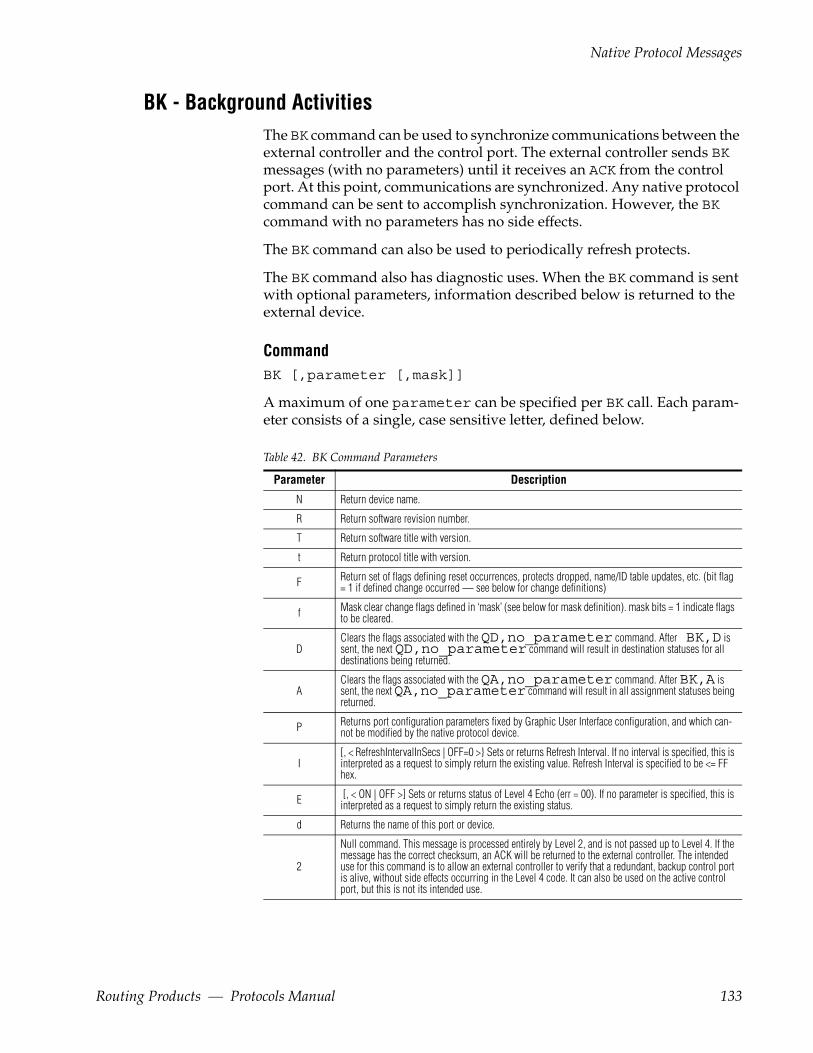
Native Protocol Messages
BK - Background ActivitiesThe BK command can be used to synchronize communications between the external controller and the control port. The external controller sends BK messages (with no parameters) until it receives an ACK from the control port. At this point, communications are synchronized. Any native protocol command can be sent to accomplish synchronization. However, the BK command with no parameters has no side effects.
The BK command can also be used to periodically refresh protects.
The BK command also has diagnostic uses. When the BK command is sent with optional parameters, information described below is returned to the external device.
CommandBK [,parameter [,mask]]
A maximum of one parameter can be specified per BK call. Each param-eter consists of a single, case sensitive letter, defined below.
Table 42. BK Command Parameters
Parameter Description
N Return device name.
R Return software revision number.
T Return software title with version.
t Return protocol title with version.
F Return set of flags defining reset occurrences, protects dropped, name/ID table updates, etc. (bit flag = 1 if defined change occurred — see below for change definitions)
f Mask clear change flags defined in ‘mask’ (see below for mask definition). mask bits = 1 indicate flags to be cleared.
DClears the flags associated with the QD,no_parameter command. After BK,D is sent, the next QD,no_parameter command will result in destination statuses for all destinations being returned.
AClears the flags associated with the QA,no_parameter command. After BK,A is sent, the next QA,no_parameter command will result in all assignment statuses being returned.
P Returns port configuration parameters fixed by Graphic User Interface configuration, and which can-not be modified by the native protocol device.
I [, < RefreshIntervalInSecs | OFF=0 >} Sets or returns Refresh Interval. If no interval is specified, this is interpreted as a request to simply return the existing value. Refresh Interval is specified to be <= FF hex.
E [, < ON | OFF >] Sets or returns status of Level 4 Echo (err = 00). If no parameter is specified, this is interpreted as a request to simply return the existing status.
d Returns the name of this port or device.
2
Null command. This message is processed entirely by Level 2, and is not passed up to Level 4. If the message has the correct checksum, an ACK will be returned to the external controller. The intended use for this command is to allow an external controller to verify that a redundant, backup control port is alive, without side effects occurring in the Level 4 code. It can also be used on the active control port, but this is not its intended use.
Routing Products — Protocols Manual 133

Section 3 — Series 7000 Native Protocol
Response
(No response if no returned data.)
Response with returned data is:
KB,parameter,data
parameter consists of a single, case sensitive letter, defined in Table 43:
Table 43. KB Response Parameters
Parameter Data
N Device name string.
R Software revision string.
T Software title with version string.
t Protocol title with version string.
I Refresh_Interval_in_Seconds. If = 0, refresh is not enabled. A value will be returned for both set and query requests (see I in Table 42).
E Echo = ON | OFF. A value will be returned for both set and query requests (see E in Table 42).
d Device_Name
P PnlLck=<ON|OFF>, ChopLck=<ON|OFF>, SlvLck=<ON|OFF>, ProtOvrd=<ON|OFF>, MonCtl=<ON|OFF>, CtlblLvls=lvlBitMap
D none
A none
2 none
F Four ASCII characters representing four HEX digits (16 bits), with bits flagging changes since flags last cleared by f parameter. Most significant hex digit is sent first (that is, b15...b12). See Table 44.
KB, F Response
For a KB, F response, the data is defined in Table 44:
Table 44. KB Command Response Bits
Bit # Meaning
0 (lsb) Reset has occurred. When reset occurs, this bit is set =1; all other flag bits are also set = 1.
1 any protects initiated by this control port were dropped.
2 destination changes
3 tieline changes
4 source changes
5 level changes
6 salvo changes
7 room changes
8 - 14 (Reserved. Always returned = 1 unless user has cleared these bits.)
15 Redundant switchover event occurred.
f, mask (none)
Here is an example of the use of BIT flags for parameters = f or F.
134 Routing Products — Protocols Manual
Native Protocol Messages
The user queries Native Protocol using BK,F — and receives a reply with parameter bit #4 set to indicate that there has been a change (addition, mod-ification, deletion) to the system source name table. The user next uses the BK,f, mask (where mask bit #4 = 1) command to clear bit #4 from the mask. The next QN,S command results in all source names being downloaded to the user. The user again queries using BK,F. The reply shows that bit #4 = 0, indicating that the source name list just downloaded is current.
Do not confuse flags discussed with f & F options with those discussed with D & A options. The QD and QA commands allow the user to download incremental changes in Destination and Assignment Status tables. The D and A options of the BK command allow the bit arrays that keep track of these incremental changes to be cleared. This allows re-synchronizing with the 7000 data base (for Destination & Assignment Status) if, for some reason, the external device resets.
Using a server timeout value (configured Refresh Rate or BK,I command) of zero is not recommended. If a connection is broken or a client crashes, the MCPU may not close the socket for a long period of time.
CH - Request Chop
Command
The format of the Chop command is identical to that of the TA Request Take command.
CH,dest_name,nbr_sources,src_name_entry1, [..., src_name_entryn]
However, the specified source names to be taken to the destination actually specify the chop source names and levels. This command results in chop-ping with the already established destination status.
To specify a chop operation, first Take sources and levels to a destination, then Chop to the same destination with the chop sources and levels.
Response
(none)
Command
(<seq_flag=’0’> for the last sequence sent.)
dest_name Destination to be taken to
nbr_sources Number of following entries (must be at least one)
Routing Products — Protocols Manual 135
Section 3 — Series 7000 Native Protocol
src_name_entryn is defined as:
src_name,level_bitmap
Response
(none)
CT - Clear Tielines
CommandCT,dest_name
Response
(none)
DA - Machine De-assign
CommandDA,dest_name,src_name
Response
(none)
PI - Protect by IndexProtect command allows the specified destination index to be protected from any source changes on the specified level from other control points. The levelbitmap is an optional parameter if not provided it protects on all levels.
CommandPI,dest_index[,level_bitmap]
Response
This will get an ER,00 response on success and an ER,nn (nn>0) on failure indicating the reason of failure.
136 Routing Products — Protocols Manual
Native Protocol Messages
Example
To protect a destination index 0x0000 (ex:-PDR1) in area index 0x02 on fourth and fifth levels, the client should issue the following command (here it is assumed the client is configured in area index 2):
PI,0000,00000018
PR - Request Protect
CommandPR,dest_name,level_bitmap
Response
No direct response, but a successful PR command will return a Directed Response Message = prot_status from the MCPU, which in turn results in a message to the external device ER, error_code = 01, echoed command = MC.
QA - Query Machine Assignment Status
CommandQA[,dest_name]
dest_name This can be either:
-An ASCII name of up to 8 characters. In this case the assignment status for a single destination will be returned, or
-Blank. If so, assignment status is returned for all desti-nations for which assignment has changed since the last time information was sent. Destination assignment information is returned for all levels (for the changed as well as unchanged levels) to which a machine is assigned. The BK,A command can be used to force return of all destination assignments.
ResponseAQ,dest_name,nbr_sources[,src_name1,...,src_namen]
Routing Products — Protocols Manual 137
Section 3 — Series 7000 Native Protocol
(<seq_flag=’0’> for the last sequence sent.)
nbr_sources Number of sources assigned to that destination which are being reported in this message sequence. If there are no sources assigned to this destination, nbr_sources = 0 will be returned.
QA (with no dest_name specified) is one of several commands whose response can consist of more than one message sequence. QA with no parameter can result in a sequence of messages for each of many destina-tions. To help the external device determine that a particular message sequence is the very last such sequence, it will be followed by a Level 4 Echo (ER,ØØ), if that Port Configuration Feature is enabled. QA (with a dest_name specified) is not followed by a Level 4 Echo.
QB - Query Alarm DefinitionsThis command allows a client to query the supported alarm definitions. Alarm definitions are not the same for all devices. E.g. some hardware sup-ports AC power alarm, some will not.
Command
The QB command can have different command syntaxes.
QB
The definitions for all supported alarms are return. The response can result in a sequence of messages for each of many alarms. To help the external device determine that a particular message sequence is the last sequence, it is followed by a Level 4 Echo (ER,ØØ).
QB[,<alarm ID>]
The definition for specified alarm is returned. If alarm ID is not present, for all supported alarms definitions are returns. In this case the end of response can be followed by a Level 4 Echo (ER,ØØ).
ResponseBQ,<alarm ID>,<max alarms>,<alarm description string>
Alarm ID Alarm ID is 4 digit hexadecimal number.
Max alarms Maximum number of device alarms, it is two digit hexadecimal number
138 Routing Products — Protocols Manual

Native Protocol Messages
QC - Query Combined Destination StatusQuery the status on combined levels of the destination. The combined levels is interpreted with respect to the first level on which the destination is present. The status returned will have the source taken to the destination on the first level on which the destination is present. This will also specify information of the other levels on which this source has been taken to.
CommandQC[,dest_name]
dest_name This can be either: - An ASCII name of up to 8 characters. In this case the status information for a single destination will be returned, or - Blank. If so, destination status information is returned for all destinations for which status has changed since the last time status information was sent. Destination status information is returned for all levels (for the changed as well as unchanged levels) which have status. The BK,D command can be used to force return of all destination status.
If there are no sources currently on some of the levels defined for the desti-nation, no information is reported for those levels.
ResponseCQ,dst_name,dst_level_bitmap[,src_name_entry1]
(<seq_flag=’0’> for the last sequence sent.)
dst_level_bitmap Describes the levels configured for destination. For source connected to first level dst_level_bitmap=0 will be returned if no source is connected.
src_name_entry1 is defined as:
<‘N’|’P’>,<‘N’|’C’>,srcm_name,level_bitmap, [device_name], [chop_src_name]
Alarm description string
a string describing of the alarm
Routing Products — Protocols Manual 139

Section 3 — Series 7000 Native Protocol
Parameters for this response are explained in Table 45.
Table 45. QC Response Parameters
Parameter Meaning
’N’ |’P’ Not-protected or Protected
’N’ | ‘C’ Not-chopping or Chopping
src_name One of the sources currently taken to the destination
level_bitmap Describes the levels of that destination which the source is on
device_name The device currently holding the protect. If the destination is not protected, or the device name is unknown, the field is left blank.
chop_src_name The name of the source chopping to this destination. The chop source name will be returned as "Chopping".
QC (with no dest_name specified) is one of several commands whose response can be more than one message sequence. QC with no parameter can result in a sequence of messages for each of many destinations. To help the external device determine that a particular message sequence is the last sequence, it is followed by a Level 4 Echo (ER,ØØ), if that Port Configura-tion Feature is enabled. QC (with a specified dest_name) is not followed by a Level 4 echo.
QD - Query Destination Status
CommandQD[,dest_name]
dest_name This can be either: - An ASCII name of up to 8 characters. In this case the status information for a single destination will be returned, or - Blank. If so, destination status information is returned for all destinations for which status has changed since the last time status information was sent. Destination status information is returned for all levels (for the changed as well as unchanged levels) which have status. The BK,D command can be used to force return of all destination status.
If there are no sources currently on some of the levels defined for the desti-nation, no information is reported for those levels.
ResponseDQ,dest_name,nbr_sources[,src_name_entry1,..., src_name_entryn]
140 Routing Products — Protocols Manual
Native Protocol Messages
(<seq_flag=’0’> for the last sequence sent.)
nbr_sources Number of sources on that destination which are being reported in this message sequence. If there are no sources on this destination at any of its levels, nbr_sources = 0 will be returned.
src_name_entryn is defined as:
<‘N’|’P’>,<‘N’|’C’>,src_name,level_bitmap, [device_name], [chop_src_name]
The chop source name will be returned as "Chopping".
Data for this response is identical to the QC command response described previously.
QD (with no dest_name specified) is one of several commands whose response can be more than one message sequence. QD with no parameter can result in a sequence of messages for each of many destinations. To help the external device determine that a particular message sequence is the last sequence, it is followed by a Level 4 Echo (ER,ØØ), if that Port Configura-tion Feature is enabled. QD (with a specified dest_name) is not followed by a Level 4 echo.
Qd - Query Destination Status
Command
The Qd command is the same format as the QD command:
Qd[,dest_name]
Response
The response to the Qd command is similar to that of the QD command, with the following differences:
• The response Command is dQ.
• The src_name returned will be NO_XPT if that condition applies to the particular set of crosspoints being reported.
Routing Products — Protocols Manual 141
Section 3 — Series 7000 Native Protocol
QE - Query Error DefinitionError messages returned through the controller channels are terse and identified by a two byte code. This command allows the user to retrieve the text describing Level 4 error codes. Level 2 error codes (associated with NAKs) are documented elsewhere.
This facility was provided so that error code interpretation could be deter-mined by the on-line controlling device, without having to look up codes in possibly outdated documentation. Error code definitions can always be determined in the latest software release.
CommandQE,error_code
error_code This can be either: - Any 2 hex digit (represented by ASCII) error code received in an ER,nn message in response to a command sent to the Amezi, or - Blank. In this case, error definition information will be returned for all error codes.
ResponseEQ,error_code,error_definition_string
(<seq_flag=’0’> for the last sequence sent.)
QH - Query Alarm StatusThe QH command facilitates to query the alarm status.
Command QH
The alarms status is returned for all alarms for which status has changed since the last time status was sent. The alarm status contains the faulty and active status. The BK, H command can send before this request to force return of all alarm's status.
QH,AB
Query absent signals alarm status. The alarms status is returned for all alarms for which signal (input/output) alarm status is faulty.
QH,AC
Query active alarm status. The alarms status is returned for all alarms except signal alarms on which alarm status is faulty.
142 Routing Products — Protocols Manual

Native Protocol Messages
ResponseHQ,Nbr_entries,alarm_entry1,….,alarm_entryN
Nbr_entries is indicates the number of alarm entries present in response.
Alarm_entry is defined as:
alarmID,alarmStateID,alarmParameter
In case of QH,AB command response the "alarm Parameter" shall contain the combination of level bitmap and connection number of input/output.
Example for QH,AB Response
The first and second sources are taken to the destination’s fourth and fifth levels. If the input signal is removed on the first two connector numbers (on two levels) , the response is shown below:
<SOH>N1HQ,AB,04,0108,1,00000003:0000,0108,1,00000003:0001,0109,1,00000003:0003,0109,1,00000003:0004,CH<EOT>
Example for QH,AC Response
If the first fan is faulty and second power supply is faulty, the response is shown below:
<SOH>N1HQ,AC,02,0101,1,0,0102,1,1,CH<EOT>
QI - Query Destination Status By Index
CommandQI,destIndex,lvlIndex
destIndex and lvlIndex are always required
ResponseIQ,destIndex,lvlIndex,<‘N’|‘P’>,<‘N’|‘C’>,srcIndex, [chop-SrcIndex]
This command allows access to destination information by using the desti-nation index vs. the destination name. Similarly, information is returned by index reference vs. name. The returned indexes will always be four ASCII hex characters with leading zeros as needed.
All indexes (dstIndex, lvlIndex, srcIndex) are zero–based hex num-bers. These indexes refer to the logical index for each entity, not to the phys-ical port number. However, the system can be configured so that port numbers are identical to index numbers. There is no disconnect index number, all indexes refer to configured entities. Valid indexes and their
Routing Products — Protocols Manual 143

Section 3 — Series 7000 Native Protocol
association with specific names can be determined using the commands: QN, ID; QN, IS; QN, L.
The chop source index will be returned as "0xFFFA".
Qi - Query Destination Status By Index
Command
The Qi command is the same format as the QI command.
Qi,destIndex,lvlIndex
Response
The response to the Qi command is similar to that of the QI command, with the following differences:
• The Response Command is iQ.
• The srcIndex returned will be 0xfffe if an error condition applies to the crosspoint being reported.
QJ - Query Destination Status By Index
CommandQJ[,dest_index]
The dest_index field may be left blank. If so, destination status is returned for all destinations for which status has changed since the last status information was sent. Destination status information is returned for all levels (changed or unchanged) which have status. The BK,D command can be used to force return of all destination status.
If there are no sources currently on some of the levels defined for the desti-nation, no information is reported for those levels.
ResponseJQ,dest_index,nbr_sources[,src_name_entry1,..., src_name_entryn]
144 Routing Products — Protocols Manual
Native Protocol Messages
(<seq_flag=’0’> for the last sequence sent for a particular destination status.)
nbr_sources Number of sources on that destination which are being reported in this message sequence. If there are no sources on this destination at any of its levels, nbr_sources = 0 will be returned.
src_name_entryn is defined as:
<‘N’|’P’>,<‘N’|’C’>,src_index,level_bitmap, [device_name], [chop_src_index]
Parameters for this response are explained in Table 46.
Table 46. QJ Command Response Parameters
Parameter Meaning
’N’ |’P’ Not-protected or Protected
’N’ | ‘C’ Not-chopping or Chopping
src_index One of the sources currently taken to the destination
level_bitmap Describes the levels of that destination which the source is on
device_name The device currently holding the protect. If the destination is not protected, or the device name is unknown, the field is left blank.
chop_src_name The name of the source chopping to this destination
chop_src_index The index of the source chopping to this destination. The chop source index will be indicated as "0xFFFA".
Returned indexes will always be four ASCII hex characters with leading zeroes as needed. All indexes (dstIndex, lvlIndex, srcIndex) are zero-based hex numbers. These indexes refer to the logical index for each entity, not to the physical port number. However, the system can be config-ured so that port and index numbers are identical. There is no disconnect index number; all indexes refer to configured entities. Valid indexes and specific name associations can be determined using the commands: QN, ID; QN,IS; QN,L.
The response to QJ (with no dest_index specified) can be more than one message sequence. QJ with no parameter can result in a sequence of mes-sages for each of many destinations. To help the external device determine that a particular message sequence is the last, it is followed by a Level 4 Echo (ER,ØØ), if that Port Configuration Feature is enabled. QJ (with a specified dest_index) is not followed by a Level 4 echo.
Routing Products — Protocols Manual 145

Section 3 — Series 7000 Native Protocol
Qj - Query Destination Status By Index
Command
The Qj command is the same format as the QJ command.
Qj[,dest_index]
Response
The response to the Qj command is similar to that of the QJ command, with the following differences:
• The Response Command is jQ.
• The srcIndex returned will be 0xfffe if that condition applies to the particular set of crosspoints being reported.
QL - Query Destination Status With Tieline Info
Command
Allows access to destination information, with possible tie-line information attached. The format of the request is the same as for the QD command.
QL[,dest_name]
dest_name This can be either: - An ASCII name of up to 8 characters. In this case the status information for a single destination will be returned (seq_flag = 0), or - Blank. If so, destination status information is returned for all destinations for which status has changed since the last time status was sent. Destination status informa-tion is returned for all levels (for changed as well as unchanged levels) which have status. The BK,D command can be used to force the return of all destina-tion status.
If there are no sources currently on some of the levels defined for the desti-nation, no information is reported for those levels.
ResponseLQ,dest_name,nbr_sources[,src_name_entry1,..., src_name_entryn]
146 Routing Products — Protocols Manual
Native Protocol Messages
(<seq_flag=’0’> for the last particular destination status report.)
nbr_sources Number of sources on that destination which are being reported in this message sequence. If there are no sources on this destination at any of its levels, nbr_sources = 0 will be returned.
src_name_entryn is defined as:
<‘N’|’P’>,<‘N’|’C’>,<‘N’|’S’>,<‘N’|’C’>, src_name, level_bitmap,[device_name],[chop_src_name], [downstreamSrcName],[downstreamChopSrcName]
Data for this response is explained in Table 47.
Table 47. LQ src_name_entry1 Description
Parameter Meaning
’N’ | ’P’ Not-protected or Protected
’N’ | ‘C’ Not-chopping or Chopping
’N’ | ’S’ No downstream source name or downstream source name exists
’N’ | ‘C’ No downstream chop source name or downstream chop source name exists
src_name One of the sources currently taken to the destination
level_bitmap Describes the levels of that destination which the source is on
device_name The device currently holding the protect. If the destination is not protected, or the device name is unknown, the field is left blank.
chop_src_name Name of the source chopping to this destination
downstreamSrcName Name of the downstream source, if any
downstreamChopSrcName Name of the downstream chopping source, if any
QL (with no dest_name specified) is one of several commands whose response can be more than one message sequence. QL with no parameter can result in a sequence of messages for each of many destinations. To help the external device determine that a particular message sequence is the very last such sequence, it will be followed by a Level 4 Echo (ER,ØØ), if that Port Configuration Feature is enabled. QL (with a specified dest_name) is not followed by a Level 4 echo.
Ql - Query Destination Status With Tieline Info
Command
The Ql command is the same format as the QL command.
Ql[,dest_name]
Routing Products — Protocols Manual 147

Section 3 — Series 7000 Native Protocol
Response
The response to the Ql command is similar to that of the QL command, with the following differences:
• The Response Command is lQ.
• The src_name returned will be NO_XPT if that condition applies to the particular set of crosspoints being reported.
148 Routing Products — Protocols Manual
Native Protocol Messages
QN - Query Names
CommandQN,parameter
One parameter can be specified per QN call. The parameters available, and their meaning, are listed in Table 48.
Table 48. QN Parameters
Parameter Meaning
S Source
D Destination
L Level
V Salvo
R Room
T Tie line
M
Y
IS Sources with source indexes
ID Destinations with destination indexes
XD Destination indices
XL Level indices
XS Source indices
S ResponseNQ,S,nbr_sources[,src_name_entry1,...,src_name_entryn]
(<seq_flag=’0’> for the last sequence sent.)
src_name_entryn is defined as:
src_name,<‘N’|’T’>,level_bitmap
<‘N’|’T’> Indicates No-TieLine or Tieline related
D ResponseNQ,D,nbr_destns[,dest_name_entry1,..., dest_name_entryn]
(<seq_flag=’0’> for the last sequence sent.)
dest_name_entryn is defined as:
Routing Products — Protocols Manual 149
Section 3 — Series 7000 Native Protocol
dest_name,<‘N’|’T’>,level_bitmap
<‘N’|’T’> Indicates No-TieLine or Tieline related
L ResponseNQ,L,nbr_levels[,lvl_name_entry1,...,lvl_name_entryn]
(<seq_flag=’0’> for the last sequence sent.)
lvl_name_entryn is defined as:
lvl_name,lvl_number,< ‘R’ | ‘N’ >
lvl_number A hex ASCII number from 00 to 1f (representing levels 00 to 31 decimal)
‘R’ | ‘N’ Specifies that this level is Restricted or Not with respect to assignments
V ResponseNQ,V,nbr_salvos[,salvo_name1,...,salvo_namen]
(<seq_flag=’0’> for the last sequence sent.)
R ResponseNQ,R,roomName,<‘1’|’2’|’3’>,nbrDestNames [,destName1,..., destNamen]
<‘1’|’2’|’3> Indicates the Room Class Type
There is one message returned per room Name.
nbrDestNames Value is <= 8.
The information for each room Name fits within one message buffer.
(<seq_flag=’0’> for the last sequence sent.)
T ResponseNQ,T,nbr_tieLines[,tieLine_entry1,...,tieLine_entryn]
(<seq_flag=’0’> for the last sequence sent.)
tieLine_entryn is defined as:
150 Routing Products — Protocols Manual

Native Protocol Messages
tieLineName,<‘N’|’R’>,beginDstName, upstreamLvlName,endSrName, downstreamLvlName
<‘N’|’R’> indicates Not-reserved or Reserved
M ResponseNQ,M,nbr_tieline_entries[,tieline_entry1,..., tieline_entryn]
(<seq_flag=’0’> for the last sequence sent.)
tieline_entry is defined as:
tieline_Name,<'N'|'R'>,tlTypeName,beginDstName, endSrcName
Y ResponseNQ,Y,nbr_tltype_entries[,tltype_entry1,..., tltype_entryn]
(<seq_flag=’0’> for the last sequence sent.)
tltype_entryn is defined as:
tltype_name,lvlbitmap
lvlbitmap includes the EndLevels in this entry, and for each consecutive 1 in the EndLevels bitmap (least significant bit first), a lvlbitmap of the BeginLevels that feed this endLevel. If there are many EndLevels in the tieline type, it may take more than one tltype_entry to send them all.
IS ResponseNQ,S,nbr_sources[,src_name_entry1,...,src_name_entryn]
(<seq_flag=’0’> for the last sequence sent.)
src_name_entryn is defined as:
src_name,src_index,<‘N’|‘T’>,level_bitmap
<‘N’|’T’> No-tieline or Tieline Related
src_index Four digit ASCII hex # with leading Ø’s
ID ResponseNQ,D,nbr_destns[,dest_name_entry1,..., dest_name_entryn]
(<seq_flag=’0’> for the last sequence sent.)
Routing Products — Protocols Manual 151
Section 3 — Series 7000 Native Protocol
dest_name_entryn is defined as:
dest_name,dest_index,<‘N’|‘T’>,level_bitmap
<‘N’|’T’> No-tieline or Tieline Related
dest_index Four digit ASCII hex # with leading Ø’s
XD ResponseNQ, XD, No_entries, dest_index_entry1… dest_index_entryN
No_entrie The numbers of available destinations count.
Dest_index_entry dest_index, Tie_flag, dest_levelbitmap
XS ResponseNQ, XS, No_entries, src_index_entry1….,src_index_entryN
No_entries The numbers of available sources count.
src_index_entry src_index, Tie_flag, src_levelbitmap
XL ResponseNQ, XL, No_entries, levelIndex1,…,levelIndexN
No_entrie The numbers of available level.
QT - Query Date & Time
CommandQT
ResponseST,yyyymmddhhmmss
hh is 00...23
152 Routing Products — Protocols Manual

Native Protocol Messages
QV - Query Salvo Status
CommandQV,salvo_name
Timed salvos are not included in the QV command.
ResponseVQ,salvo_name,nbr_entries[,entry1,...,entryn]
(<seq_flag=’0’> for the last sequence sent.)
entryn is defined as follows:
dest_name,src_name,level_bitmap
ST - Request Set Date & Time
CommandST,yyyymmddhhmmss
The parameters are in ASCII (Table 49).
Table 49. Date and Time Values
Parameter Values
yyyy 1993...2999
mm 01...12
dd 01...31
hh 00...23
mm 00...59
ss 00...59
Response
(none)
TA - Request Take
CommandTA,dest_name,nbr_sources,src_name_entry1,..., src_name_entryn]
Routing Products — Protocols Manual 153
Section 3 — Series 7000 Native Protocol
(<seq_flag=’0’> for the last sequence sent.)
dest_name Destination to be taken to
nbr_sources Number of following entries (must be at least one)
src_name_entryn is defined as:
src_name,level_bitmap
Response
(none)
TD - Request Take Destination
CommandTD,dest_name,src_name_entry
(<seq_flag=’0’> for the last sequence sent.)
dest_name Destination to be taken to
src_name_entryn is defined as:
src_name[,levelbitmap]
With no level bitmap specified, the source will be taken to all levels of the destination.
Response
(none)
TI - Request Take Index With Level Index
CommandTI,destIndex,srcIndex[,levelIndex]
This command allows a Take Request to be specified using indexes vs. names. If no level Index is specified, then an all-level take occurs.
All indexes (dstIndex, lvlIndex, srcIndex) are zero–based hex num-bers. These indexes refer to the logical index for each entity, not to the phys-ical port number. However, the system can be configured so that port
154 Routing Products — Protocols Manual
Native Protocol Messages
numbers are identical to index numbers. There is no disconnect index number, all indexes refer to configured entities. Valid indexes and their association with specific names can be determined by using the commands: QN, L; QN, ID; QN, IS.
Response
(none)
TJ - Request Take Index With Level Bitmap
CommandTJ,dest_index,nbr_sources,src_name_entry1,..., src_name_entryn]
(<seq_flag=’0’> for the last sequence sent.)
dest_index Destination to be taken to
nbr_sources Number of following entries (must be at least one)
src_name_entryn is defined as:
src_index,level_bitmap
All indexes (dstIndex, lvlIndex, srcIndex) are zero–based hex num-bers. These indexes refer to the logical index for each entity, not to the phys-ical port number. However, the system can be configured so that port numbers are identical to index numbers. There is no disconnect index number. All indexes refer to configured entities. Valid indexes and their association with specific names can be determined by using the commands: QN, L; QN, ID; QN, IS.
Response
(none)
TM - Request Take Monitor Destination
CommandTM,dest_name
Response
(none)
Routing Products — Protocols Manual 155

Section 3 — Series 7000 Native Protocol
TS - Request Take Salvo
CommandTS,salvo_name
salvo_name An untimed salvo
Response
(none)
UI - Unprotect by IndexUnprotect command allows the protect on the specified destination to be removed on the specified level. The levelbitmap is an optional parameter if not provided it unprotect on all levels.
Command
UI, dest_index[,level_bitmap]
Response
This will get an ER,00 response on success and an ER,nn (nn>0) on failure indicating the reason of failure.
UP - Request Unprotect
CommandUP,dest_name,level_bitmap
Response
No direct response. However, a successful UP command will result in the return of a Directed Response Message = prot_status from the MCPU, which in turn results in a message to the external device ER, error_code = 01, echoed command = MC.
156 Routing Products — Protocols Manual
Client Subscription Message Descriptions
Client Subscription Message Descriptions
SB - SubscribeSubscribe request for status change information. The specific information for which the client subscribes is decided based on the subscription type and parameters sent as part of SB command.
Command SB, Subscription_type [, parameters]
Refer the Table 50 on page 158 for the list of available subscription type acronyms.
Response
Subscription request will get an ER,00 response on success and an ER,nn (nn>0) on failure indicating the reason of failure.
UB – Unsubscribe RequestUnsubscribe request for already subscribed status change information.
The specific information for which the client un-subscribe is decided on the subscription
Type and parameters sent as part of the UB command.
Command UB,subscription_type[,parameters]
Refer to Table 50 on page 158 for the list of available subscription type acro-nyms.
Response
Unsubscription request will get an ER,00 response on success and an ER,nn (nn>0) on failure indicating the reason of failure.
Routing Products — Protocols Manual 157

Section 3 — Series 7000 Native Protocol
Server Originated Message Descriptions
NY – NotificationAn asynchronous notification is sent to the client by the server whenever the subscribed status information changes.
Notification Format:NY, subscription_type[,parameters]
Refer to Table 50 for the list of available subscription type acronyms.
Table 50. Subscription Type Descriptionss
Subscription Type Meaning
AL Subscription for alarm status change
DJ Subscription for destination status change by index
DS Subscription for destination status change by name
EV Subscription for events (Take, Salvo, Protect, Unprotect)
Subscription/Unsubscription Commands Usage
Alarm Status ChangeA NP client can subscribe for alarm status changes of one or group of alarms. Whenever the alarm status changes in the system all the subscribed clients receive notification about the alarm status change.
Subscribe for Alarm Status Change
Subscribe for alarm status change can be used in the following fomats.
CommandSB, AL
The client receives notification, whenever the alarm status of any alarm changes.
CommandSB, AL, AlarmID
158 Routing Products — Protocols Manual

Subscription/Unsubscription Commands Usage
The client receives notification only when the status of the specified alarm changes.
CommandSB, AL, AlarmIDX, AlarmIDY
The client receives notification, when the status of the specified alarm changes between AlarmIDX to AlarmIDY status.
Here the range should be specified in ascending order of indices only.
Notification for Alarm Status Change
Whenever the status changes for an alarm, all NP clients that have sub-scribed for the same shall receive notifications in the following format.
NY, AL, Nbr_entries, alarm_entry1,….,alarm_entryN.
Nbr_entries number of alarms
Alarm_entry alarmID, alarmStateID, alarm Parameter
Unsubscribe for Alarm Status Change
Unsubscribe for alarm status change can be used in the following formats.
CommandUB, AL
Unsubscribe for alarm status change notification for all alarms.
CommandUB, AL, AlarmID
Unsubscribe for specified alarms status change notification.
CommandUB, AL, AlarmID1, AlarmIDN
Unsubscribe for range of alarms status change notification.
Here the range should be specified in ascending order of indices only
Routing Products — Protocols Manual 159
Section 3 — Series 7000 Native Protocol
Destination Status Change By IndexA NP client can subscribe for destination status change of one or a group of destinations. Whenever the status of a destination changes, all the clients that have subscribed for that Destination status receives a notification.
Subscribe for Status Change
Subscribe command for destination status change can be used in the fol-lowing formats.
CommandSB, DJ
The client receives notifications, whenever the status of any destination changes.
CommandSB, DJ, dest_Index
The client receives notification, whenever the destination status is changed for specified destination.
Command SB, DJ, dest_index1, dest_indexN
The client receives notification, whenever the destination status is changed for the destinations between the dest_index1 and dest_indexN.
Example
To subscribe for destination status change for destinations “0000” to “0008”, the client should issue the following command
SB, DJ, 0000, 0008
The client receives notification, whenever the destination status is changed for the destination indices 0000,0001,0002,0003,0004,0005,0006,0007,0008
Notification for Destination Status Change
Whenever the destination status is changed all NP clients that have sub-scribed for the same shall receive notifications in the following format.
160 Routing Products — Protocols Manual
Subscription/Unsubscription Commands Usage
NY, DJ, dest_index,nbr_sources, src_name_entry1,…,src_name_entryN.
Nbr_sources Number of sources on that destination which are being reported in this message sequence.
Src_name_entry is defined as:
<’N’/’P’>,<’N’/’C’>,src_index,level_bitmap, [device_name],[chop_src_index]
The chop source index will be returned as "0xFFFA".
Note This notification is similar to QJ response.
Unsubscribe for Status Change
Unsubscribe command for destination status change can be used in the fol-lowing formats.
Command UB, DJ
Unsubscribe for destination status change notification of any destination status change.
Command UB, DJ, dest_index
Unsubscribe for destination status change notification for specified desti-nation.
Command UB, DJ, dest_index1,dest_indexN
Unsubscribe for destination status change notification for specified desti-nation range.
Example
To unsubscribe for destination status change notification for a destination range “0000” to “0008” the client should issue the following command
UB, DJ, 0000, 0008
Routing Products — Protocols Manual 161
Section 3 — Series 7000 Native Protocol
Destination Status Change By NameA NP client can subscribe for destination status change of one or a group of destinations. Whenever the status of a destination changes, all the clients that have subscribed for that Destination status receives a notification.
Subscribe for Status Change
Subscribe command for destination status change can be used in the fol-lowing formats.
CommandSB, DS
The client receives notifications, whenever the status of any destination changes.
CommandSB, DS, dest_name
The client receives notification, whenever the destination status is changed for specified destination.
Example
To subscribe for destination status change for a destination “Dest1” the client should issue the following command
SB, DS, Dest1
Notification for Destination Status Change
Whenever the destination status is changed all NP clients that have sub-scribed for the same shall receive notifications in the following format.
NY,DS,dest_name, nbr_sources, src_name_entry1,…,src_name_entryN
Nbr_sources Number of sources on that destination which are being reported in this Message sequence.
Src_name_entry is defined as:
<’N’/’P’>,<’N’/’C’>,src_name, level_bitmap, [device_name],[chop_src_name]
The chop source name will be returned as "Chopping".
Note This notification is similar to QD response
162 Routing Products — Protocols Manual

Subscription/Unsubscription Commands Usage
Unsubscribe for Status Change
Unsubscribe command for destination status change can be used in the fol-lowing formats.
Command UB, DS
Unsubscribe for destination status change notification of any destination status change.
Command UB, DS, dest_name
Unsubscribe for destination status change notification for specified desti-nation.
Example
To unsubscribe for destination status change notification for a destination “Dest1” the client should issue the following command
UB, DS, Dest1
Subscription for EventsA NP client can subscribe for the take,Salvo,Protect and Unprotect opera-tions. Whenever the take/Salvo/Protect/Unprotect operation is per-formed all NP clients that have subscribed for the same shall receive notification.
Command SB,EV
The client receives notifications, whenever the take/Salvo/Protect/Unpro-tect happens.
Notification for Events
Whenever the take/Salvo/Protect operation is performed all RCL/NP clients that have subscribed for the same shall receive notifications in the following format:
Routing Products — Protocols Manual 163

Section 3 — Series 7000 Native Protocol
NY,EV,timestamp, name of the initiating control device, operation_type, operation_parameters
Timestamp Operation requested time. The time format is: DDMONYYYY HH:MM: SS.FF For example: 16Jan2005 21:21:18.02. If the client connected to WIN32 CPS system the "FF" field shows as "00" always.
Name of the initiat-ing control device
The name of the device initiating the opera-tion. In case, the device does not have name the IP address of the device shall be used. The IP address be sent as a string in dot notation.
Operation_type The operation types can be “Take” or ”Salvo” or ”Protect” or “Unprotect”
Operation_parameters Differ for each operation type.
The Take operation parameters are destination index ,source index and level bitmap. (The level bitmap shall be shown as 0xFFFFFFFF if the take happened on all the configured levels of the destination. )
The salvo operation parameter is name of the salvo.
The protect/unprotect operation parameter are destination index and level bitmap.
Unsubscribe for Events
Command UB,EV
Unsubscribe for events notifications.
164 Routing Products — Protocols Manual

Section 4Serial Node Controller Protocol
IntroductionThis section describes the format of the Series 7000 Serial Node Controller (SNC) RS-485 Pro-Bel SW-P-02x (extended) protocol. Some additional information about the Pro-Bel SW-P-02 standard protocol is also included.
This protocol is designed to allow an Omnibus system to control a Series 7000 Node Controller directly, using the established Pro-Bel protocol and this extension to that protocol. The extension allows larger Series 7000 mes-sages (in SSML protocol format) to be transferred to and from the Series 7000 Node Controller. Basic matrix control can be accomplished using the standard Pro-Bel 02 protocol, and so use of the Pro-Bel 02x protocol is not required but can add functionality.
SSML is a Grass Valley proprietary protocol used to communicate within the Series 7000 system via the Node Control Bus. Formatting and use of Series 7000 SSML messages communicated via Pro-Bel 02x are not dis-cussed in this document. Contact Grass Valley Customer Service if you require this information.
Physical Layer
RS-485The Serial Node Controller physical interface is RS-485. A serial cable is required to connect the Series 7000 Node Controller to the controlling device. Maximum cable length is determined by customer needs, limited only by the RS-485 standard and the customer site environmental noise.
Routing Products — Protocols Manual 165

Section 4 — Serial Node Controller Protocol
Link layer
Format TypesTwo link layer protocols are defined:
• Pro-Bel SW-P-02 as defined in Pro-Bel’s General Switcher Communica-tions Protocol, Issue 7 of May 5, 1992. This protocol type is referred to as Type 02, and
• A Pro-Bel SW-P-02x, an extension for communicating Series 7000 Node Controller message types requiring 8 bits. This protocol is referred to as Type 02x.
Link CharacteristicsCommunication is via a full-duplex RS-485 asynchronous link at:
• 8 data bits,
• 1 stop bit,
• No parity, and
• 38400 baud.
Protocol message types are sent and received in any order as needed. The two protocols are mixed on the link. It is up to the sender to choose the correct protocol type for a particular message, and up to the receiver to be able to correctly parse either message type.
Some messages transmitted to the Series 7000 Node Controller by the con-trolling device require responses. It is not necessary for the controlling device to wait for a response before transmitting further messages.
Packet Pacing
Pacing is required by the controlling device between packets transmitted to the Series 7000 Node Controller. The method of pacing is to be a delay between the last character of one packet and the first character of the suc-ceeding packet. This value is to be selected at test, but the current best esti-mate is two character times (at 38400 baud = 500 μs).
166 Routing Products — Protocols Manual
Link layer
Handshaking
There is no link layer handshaking. No acknowledgment or error response is generated by the receiver upon reception of an 02 or 02x packet at the link layer (e.g., ACK, NAK). If the receiver detects any error (checksum, unex-pected byte count, unrecognized command) then the message is ignored. If a SOM or SOMx is received in the middle of an incoming packet, all the pro-ceeding bytes of the incoming packet are discarded and a new packet is begun.
Success or failure of packet transmission can only be accomplished at the Packet Layer, either by receiving the corresponding response for messages that have responses, or by querying the Series 7000 Node Controller for the information needed for a verification (such as a crosspoint query via an Interrogate command). Refer to each message definition to determine what responses, if any, are expected.
The 02 Protocol
02 Message Format<SOM> <command> <message> <checksum>
<SOM> (1 byte) Start of message = 0x0FF
<command> (1 byte) Message type. Also defines message length.
<message> (0-n bytes) Message body.
<checksum> (1 byte) 7 bit, sum all message bytes, excluding SOM, Count and any Bit7ESCs. Then compliment the Sum and Increment the sum by value of 1. Apply mask 0x7F (or value with binary 01111111). The result is the message checksum.
Special 02 Protocol Characters
SOM (0x0FF) Signals to the receiver the start of a Type 02 message. Any incoming message is completed when the number of bytes expected are received. Any message not com-pletely received when a SOM (or SOMx) is received is simply discarded, and the new message signaled by the SOM(x) is received.
Routing Products — Protocols Manual 167
Section 4 — Serial Node Controller Protocol
The 02x Protocol
02x Message Format:<SOMx> <command> <message> <checksum>
<SOMx> (1 byte) Start of message = 0x0FE
<count> (1 byte) Message length in bytes. Only includes <mes-sage> field. Does not include <SOM>, <count>, or <checksum> fields. Also does not include any 7 bit escape (BIT7ESC == F1) bytes.
<message> (0-120 bytes) Message body. Maximum 120 bytes. Does not include any BIT7ESC bytes.
<checksum> (1 byte) 7 bit, sum all message bytes, excluding SOMx, Count and any Bit7ESCs. Then compliment the Sum and Increment the sum by value of 1. Apply mask 0x7F (or value with binary 01111111). The result is the message checksum.
Special 02x Characters
SOMx (0x0FE) Signals to the receiver the start of a TYPE 02x mes-sage. Any incoming message is completed when the number of bytes expected are received. Any message not completely received when a SOMx (or SOM) is received is simply discarded, and the new message signaled by the SOM(x) is received.
BIT7ESC (0x0F1) Signals to the receiver to set the previous byte’s most significant bit. For example, a 2 is received in byte 5, then an F1 is received in byte 6. The receiver must then set the m.s.b. of byte 5, changing byte 5’s value from 2 to 130. The F1 is then discarded and is not counted towards the COUNT field’s message byte count. Note: Series 7000/Node Controller traffic should not require an excess of data greater than 127.
168 Routing Products — Protocols Manual
Packet Layer
Packet Layer
Link MessagesThe following two messages are required to establish communications between a controlling device and a Matrix Controller or a Node Controller. Until these messages are received, the Matrix Controller or Node Con-troller it will not respond to other messages from the controlling device.
Routing Products — Protocols Manual 169

Section 4 — Serial Node Controller Protocol
MSG_SET_PRIMARY
Command
Direction: Controlling Device -> Series 7000 Node Controller
Purpose: Set the Matrix Controller or Node Controller to primary
Hexadecimal: FE 02 53 22 0B
Rate: On demand
Table 51. MSG_SET_PRIMARY Command
Length (5 Bytes) Element Description
BYTE SOMx = 0x0Fe
BYTE ByteCount = 0x002
BYTE Socket = 0x053
BYTE msg Type = 0x022
BYTE Checksum = 0x00B
Response
Direction: Series 7000 Node Controller -> Controlling Device
Purpose: Response
Hexadecimal: FE 05 2B 0E 01 00 01 45
Table 52. MSG_SET_PRIMARY Response
Length (8 Bytes) Element Description
BYTE SOMx = 0x0Fe
BYTE ByteCount = 0x05
BYTE Socket = 0x2B
BYTE msg Type = 0x0E
BYTE = 0x01
BYTE = 0x00
BYTE = 0x01
BYTE Checksum = 0x45
170 Routing Products — Protocols Manual

Packet Layer
MSG_GET_NC_HEALTH
Command
Direction: Controlling Device -> Series 7000 Node Controller
Purpose: Get the health Message from the Matrix Controller or Node Controller
Hexadecimal: FE 02 54 1A 12
Rate: On demand
Table 53. MSG_GET_NC_HEALTH Command
Length (5 Bytes) Element Description
BYTE SOMx = 0x0FE
BYTE ByteCount = 0x002
BYTE Socket = 0x054
BYTE msg Type = 0x01A
BYTE Checksum = 0x012
Response
Direction: Series 7000 Node Controller -> Controlling Device
Purpose: Response
Hexadecimal: FE 05 2B 32 00 28 02 79
Table 54. MSG_GET_NC_HEALTH Response
Length (8 Bytes) Element Description
BYTE SOMx = 0x0Fe
BYTE ByteCount = 0x05
BYTE Socket = 0x2B
BYTE msg Type = 0x32
BYTE = 0x00
BYTE = 0x28
BYTE = 0x02
BYTE Checksum = 0x79
The Type 02 Command SetFor reference, the following commands used by the standard Pro-Bel 02 protocol are included in this document. For greater detail, see the Pro-Bel
Routing Products — Protocols Manual 171

Section 4 — Serial Node Controller Protocol
General Switcher Communication Protocol, Issue 7 of May 5 1992 (Appendix 1). All values in the Type 02 commands, excepting the SOM Byte 0x0FF, are specified as decimal values.
Interrogate (1)
Direction: Controlling Device -> Series 7000 Node Controller
Purpose: Request for Destination Status
Rate: On demand
Table 55. Interrogate Command
Length (5 bytes) Element Description
Byte SOM = 0x0FF
Byte Command = 1
Byte Multiplier:Bit 7Bit 4-6
Bit 3BIT 0-2
= 0Destination number DIV 128All main router destinations.= 0= 0
Byte Destination Destination number MOD 128
Byte Checksum
Connect (2)
Direction: Controlling Device -> Series 7000 Node Controller
Purpose: Request a crosspoint connect
Rate: On demand
Table 56. Connect Command
Length (6 bytes) Element Description
BYTE SOM = 0x0FF
BYTE Command = 2
BYTE MultiplierBit 7Bit 4-6Bit 3BIT 0-2
= 0Destination number DIV 128= 0= Source number DIV 128
BYTE Destination Destination number MOD 128
BYTE Source Source number MOD 128
BYTE Checksum Calculated
172 Routing Products — Protocols Manual
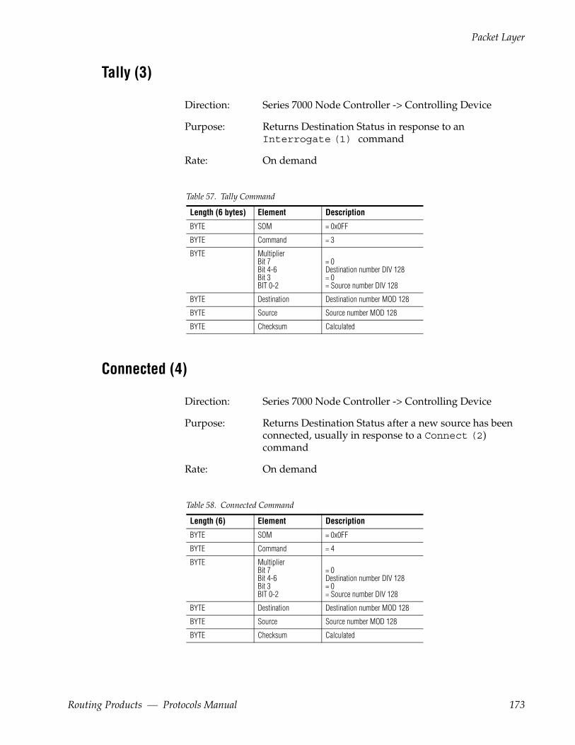
Packet Layer
Tally (3)
Direction: Series 7000 Node Controller -> Controlling Device
Purpose: Returns Destination Status in response to an Interrogate (1) command
Rate: On demand
Table 57. Tally Command
Length (6 bytes) Element Description
BYTE SOM = 0x0FF
BYTE Command = 3
BYTE MultiplierBit 7Bit 4-6Bit 3BIT 0-2
= 0Destination number DIV 128= 0= Source number DIV 128
BYTE Destination Destination number MOD 128
BYTE Source Source number MOD 128
BYTE Checksum Calculated
Connected (4)
Direction: Series 7000 Node Controller -> Controlling Device
Purpose: Returns Destination Status after a new source has been connected, usually in response to a Connect (2) command
Rate: On demand
Table 58. Connected Command
Length (6) Element Description
BYTE SOM = 0x0FF
BYTE Command = 4
BYTE MultiplierBit 7Bit 4-6Bit 3BIT 0-2
= 0Destination number DIV 128= 0= Source number DIV 128
BYTE Destination Destination number MOD 128
BYTE Source Source number MOD 128
BYTE Checksum Calculated
Routing Products — Protocols Manual 173
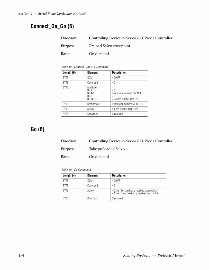
Section 4 — Serial Node Controller Protocol
Connect_On_Go (5)
Direction: Controlling Device -> Series 7000 Node Controller
Purpose: Preload Salvo crosspoint
Rate: On demand
Table 59. Connect_On_Go Command
Length (6) Element Description
BYTE SOM = 0x0FF
BYTE Command = 5
BYTE MultiplierBit 7Bit 4-6Bit 3BIT 0-2
= 0Destination number DIV 128= 0= Source number DIV 128
BYTE Destination Destination number MOD 128
BYTE Source Source number MOD 128
BYTE Checksum Calculated
Go (6)
Direction: Controlling Device -> Series 7000 Node Controller
Purpose: Take preloaded Salvo
Rate: On demand
Table 60. Go Command
Length (4) Element Description
BYTE SOM = 0x0FF
BYTE Command = 6
BYTE Action = 0 then Set previously received crosspoints= 1 then Clear previously received crosspoints
BYTE Checksum Calculated
174 Routing Products — Protocols Manual

Packet Layer
Connect_On_Go_Acknowledge (12)
Direction: Series 7000 Node Controller -> Controlling Device
Purpose: Response to a Connect_On_Go (5) command
Rate: On demand
Table 61. Connect_On_Go_Acknowledge Command
Length (6) Element Description
BYTE SOM = 0x0FF
BYTE Command = 12
BYTE MultiplierBit 7Bit 4-6Bit 3BIT 0-2
= 0Destination number DIV 128= 0= Source number DIV 128
BYTE Destination Destination number MOD 128
BYTE Source Source number MOD 128
BYTE Checksum Calculated
Go_Done (13)
Direction: Series 7000 Node Controller -> Controlling Device
Purpose: Response to a Go (6) command
Rate: On demand
Table 62. Go_Done Command
Length (4) Element Description
BYTE SOM = 0x0FF
BYTE Command = 13
BYTE Action = 0 then Set previously received crosspoints= 1 then Clear previously received crosspoints
BYTE Checksum Calculated
Routing Products — Protocols Manual 175

Section 4 — Serial Node Controller Protocol
176 Routing Products — Protocols Manual
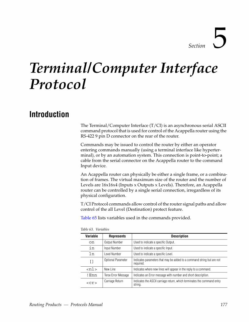
Section 5Terminal/Computer Interface Protocol
IntroductionThe Terminal/Computer Interface (T/CI) is an asynchronous serial ASCII command protocol that is used for control of the Acappella router using the RS-422 9 pin D connector on the rear of the router.
Commands may be issued to control the router by either an operator entering commands manually (using a terminal interface like hyperter-minal), or by an automation system. This connection is point-to-point; a cable from the serial connector on the Acappella router to the command Input device.
An Acappella router can physically be either a single frame, or a combina-tion of frames. The virtual maximum size of the router and the number of Levels are 16x16x4 (Inputs x Outputs x Levels). Therefore, an Acappella router can be controlled by a single serial connection, irregardless of its physical configuration.
T/CI Protocol commands allow control of the router signal paths and allow control of the all Level (Destination) protect feature.
Table 65 lists variables used in the commands provided.
Table 63. Variables
Variable Represents Description
on Output Number Used to indicate a specific Output.
in Input Number Used to indicate a specific Input.
ln Level Number Used to indicate a specific Level.
[] Optional Parameter Indicates parameters that may be added to a command string but are not required.
<nl> New Line Indicates where new lines will appear in the reply to a command.
!Enn Terse Error Message Indicates an Error message with number and short description.
<cr> Carriage Return Indicates the ASCII carriage return, which terminates the command entry string.
Routing Products — Protocols Manual 177
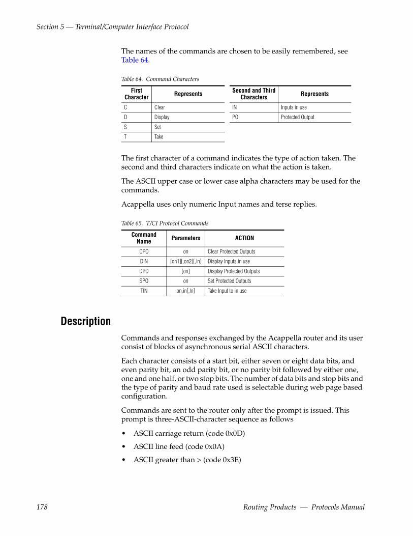
Section 5 — Terminal/Computer Interface Protocol
The names of the commands are chosen to be easily remembered, see Table 64.
Table 64. Command Characters
FirstCharacter Represents Second and Third
Characters Represents
C Clear IN Inputs in use
D Display PO Protected Output
S Set
T Take
The first character of a command indicates the type of action taken. The second and third characters indicate on what the action is taken.
The ASCII upper case or lower case alpha characters may be used for the commands.
Acappella uses only numeric Input names and terse replies.
Table 65. T/CI Protocol Commands
Command Name Parameters ACTION
CPO on Clear Protected Outputs
DIN [on1][,on2][,ln] Display Inputs in use
DPO [on] Display Protected Outputs
SPO on Set Protected Outputs
TIN on,in[,ln] Take Input to in use
DescriptionCommands and responses exchanged by the Acappella router and its user consist of blocks of asynchronous serial ASCII characters.
Each character consists of a start bit, either seven or eight data bits, and even parity bit, an odd parity bit, or no parity bit followed by either one, one and one half, or two stop bits. The number of data bits and stop bits and the type of parity and baud rate used is selectable during web page based configuration.
Commands are sent to the router only after the prompt is issued. This prompt is three-ASCII-character sequence as follows
• ASCII carriage return (code 0x0D)
• ASCII line feed (code 0x0A)
• ASCII greater than > (code 0x3E)
178 Routing Products — Protocols Manual
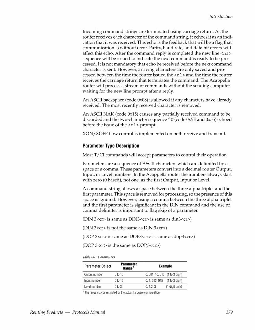
Introduction
Incoming command strings are terminated using carriage return. As the router receives each character of the command string, it echoes it as an indi-cation that it was received. This echo is the feedback that will be a flag that communication is without error. Parity, baud rate, and data bit errors will affect this echo. After the command reply is completed the new line <nl> sequence will be issued to indicate the next command is ready to be pro-cessed. It is not mandatory that echo be received before the next command character is sent. However, arriving characters are only saved and pro-cessed between the time the router issued the <nl> and the time the router receives the carriage return that terminates the command. The Acappella router will process a stream of commands without the sending computer waiting for the new line prompt after a reply.
An ASCII backspace (code 0x08) is allowed if any characters have already received. The most recently received character is removed.
An ASCII NAK (code 0x15) causes any partially received command to be discarded and the two-character sequence ̂ U (code 0x5E and 0x55) echoed before the issue of the <nl> prompt.
XON/XOFF flow control is implemented on both receive and transmit.
Parameter Type Description
Most T/CI commands will accept parameters to control their operation.
Parameters are a sequence of ASCII characters which are delimited by a space or a comma. These parameters convert into a decimal router Output, Input, or Level numbers. In the Acappella router the numbers always start with zero (0 based), not one, as the first Output, Input or Level.
A command string allows a space between the three alpha triplet and the first parameter. This space is removed for processing, so the presence of this space is ignored. However, using a comma between the three alpha triplet and the first parameter is significant in the DIN command and the use of comma delimiter is important to flag skip of a parameter.
(DIN 3<cr> is same as DIN3<cr> is same as din3<cr>)
(DIN 3<cr> is not the same as DIN,3<cr>)
(DOP 3<cr> is same as DOP3<cr> is same as dop3<cr>)
(DOP 3<cr> is the same as DOP,3<cr>)
Table 66. Parameters
Parameter Object Parameter Rangea
a The range may be restricted by the actual hardware configuration.
Output number 0 to 15 0, 001, 10, 015 (1 to 3 digit)
Input number 0 to 15 0, 1, 013, 015 (1 to 3 digit)
Level number 0 to 3 0, 1,2, 3 (1 digit only)
Example
Routing Products — Protocols Manual 179

Section 5 — Terminal/Computer Interface Protocol
Limitations• A client can send a maximum of 32 bytes per second under normal load
conditions. Clients need to be programmed to ensure that any combi-nation of commands sent does not exceed this maximum. For example, a TIN (Take) command (without level bitmap) requires 8 bytes. A DIN command requires 4 bytes. In this example two TIN commands and four DIN commands can be sent every second.
T/CI Command Descriptions
TIN
COMMANDTIN on,in[,ln]<cr>
Description Take Input.
This command modifies a signal path in the router matrix.
Both a router Output number and a router Input number are required parameters. Optionally, a control Level number may be included. If the Level is omitted, the command will affect all control Levels present in the router.
This command response has two formats
• An All Level Take of Input numbers on an Output, or
• A single Level Take of an Input number on an Output.
If the optional Level parameter is omitted, the response is
<nl>nnn in0 in1 in2 in3
Where nnn is replaced by the Output number, and in0 in1 in2 in3 is replaced by the 3 digit Input number in use on each control Level for this Output. Three spaces follow each Input number.
If the Level number is included in the command, the response is
<nl>nnn in
Where again nnn is replaced by the Output number, and in is replaced by only the 3 digit Input number in use on the specified Level of this Output.
180 Routing Products — Protocols Manual

T/CI Command Descriptions
Examples
Table 67. TIN Command Examples
TIN4 2 1<cr> Command line
<nl>004 002 Response shows only Level 1 of Output 4 is taken to Input 2
<nl>> Greater than > is prompt character
tin 13 4<cr> Command line
<nl>013 004 004 004 ---
a If the indicated Output and Level have no crosspoint, the Input number is replaced by --- (3dashes).
a Response shows Levels 0, 1, and 2, of Output 13 is taken to Input 4, Level 3 has no crosspoints
<nl>> Greater than > is prompt character
Errors
Errors that can be returned using the TIN command are in Table 68.
Table 68. Error Codes for TIN Command
Error Code Explanation
!E02 !E02 - Output Number too big or Invalid Format (page 188)
!E04 !E04 - Level Number too big or Invalid Format (page 189)
!E07 !E07 - Input Number too big or Invalid Format (page 189)
!E12 !E12 - Output Number Required (page 189)
!E13 !E13 - Input Number Required (page 189)
!E75 !E75 - Output Protected from Change to a Different Input (page 189)
After issuance of any of the above error messages, the command termi-nates.
DIN
COMMANDDIN [on1][,on2][,ln]
Description Display Inputs in use.
The response to this command is the router matrix current status.
This response is in one of two forms
• An All Level status of Input numbers on an Output, or
• A single Level status of Input numbers on an Output.
Omitted (on1) will default to Output = 0.
Routing Products — Protocols Manual 181
Section 5 — Terminal/Computer Interface Protocol
Omitted (on2) will default to Output = maximum.
Omitting the Level (ln) parameter creates an All Level status.
With no Level parameter, the response will start with the selected Output in router (on1), with multiple Inputs (in0-3) indexed in the line behind the colon. The first Input number is always level0, next is level1, level2, level3.
<nl>nnn in0 in1 in2 in3<nl>nnn in0 in1 in2 in3….<nl>nnn in0 in1 in2 in3
Where nnn is replaced by the Output number, and in0 in1 in2 in3 is replaced by the 3 digit Input number in use on each control Level for this Output. Three spaces follow each Input number.
The selection of which and how many Output number lines replied are set by the choice of on1 and on2 to create the range of desired Outputs. If on1=1 and on2=3 Output lines start with 1 and end at 3. If on1 is skipped (din ,3) using a comma, the Output lines start with 0 and end at on2=3. If on1, on2, ln are missing the default is multiple lines of all Outputs and all 4 Levels per line.
If the Level number (ln) is included in the command, the response is
<nl>nn in
Where nnn is replaced by the specified Output number, and in is replaced by the 3 digit Input number in use on control Level (ln) for this specified Output.
182 Routing Products — Protocols Manual
T/CI Command Descriptions
Examples
Table 69. DIN Command Examples
din<cr> Command line omits on1,on2, and ln parameters
<nl>000 012 012 012 012 Output 0 has Input 12 on all Levels 1,2,3,4
<nl>001 014 008 008 008 Output 1 has Input 14 on Level 0, but Input 8 on Levels 1,2,3
…. Lines 002 to 014 are omitted for this example of 16 Output router
<nl>015 001 002 003 004<nl>> Greater than > is prompt character
DIN 3<cr> Command line has on1, but omits on2 and ln parameters
<nl>003 010 010 010 010<nl>>
DIN 3,4<cr> Command line has on1 and on2, but omits ln parameter
<nl>003 010 010 010 010 Output 3 is starting Output and finish at Output 4
<nl>004 011 012 013 014<nl>>
DIN,1<cr> Command line has skipped on1, has on2, and omits ln parameter
<nl>000 000 000 000 000 Output 0 is starting Output and finish at Output 1
<nl>001 001 002 003 004<nl>>
DIN,,2<cr> Command line skips on1,on2, but has ln parameter
<nl>000 013 Output 0 has Input 13 on Level 2
<nl>001 014 Output 1 has Input 14 on Level 2
….…. Lines 002 to 014 are omitted for this example of 16 Output router
<nl>015 001 Output 15 has Input 1 on Level 2
<nl>>
DIN 5,,1<cr> Command line skips on2, but has on1 and ln parameter
<nl>005 015 Output 5 has Input 15 on Level 1
<nl>>
DIN, 1,3<cr> Command line has skipped on1, has on2, and ln parameter
<nl>000 012 Output 0 has Input 12 on Level 3
<nl>001 008 Output 1 has Input 8 on Level 3
<nl>
DIN 1,2,3<cr> Command line has on1, has on2, and ln parameter
<nl>001 008 Output 1 has Input 8 on Level 3
<nl>002 002 Output 2 has Input 2 on Level 3
<nl>
Routing Products — Protocols Manual 183

Section 5 — Terminal/Computer Interface Protocol
Errors
If the indicated Output and Level have no crosspoint, the Input number is replaced by --- (3dashes).
Errors that can be returned using the TIN command are in Table 70.
Table 70. Error Codes for DIN Command
Error Code Explanation
!E02 !E02 - Output Number too big or Invalid Format (page 188)
!E04 !E04 - Level Number too big or Invalid Format (page 189)
After issuance of any of the above error messages, the command termi-nates.
DPO
COMMANDDPO [on]
Description Display Protected Outputs
The response to this command is the protect status of the router Output.
This response is in one of two forms
• If the optional Output number parameter is omitted, the response will be multiple lines, one for each Output in router, with bit per Level status in the line behind the colon.
Note This router will only protect All Levels as a monolith. Individual Levels cannot be separately protected if other Levels of this same Output are not.
Thus, abcd is always 0000 (not protected), or 1111 (protected) in the response.
<nl>nnn abcd<nl>nnn abcd….<nl>nnn abcd
Where nnn is replaced by the Output number, and abcd is replaced by the protect status on each control Level for this Output.
• If the Output number is included in the command, the response is a single line
<nl>nnn abcd
184 Routing Products — Protocols Manual

T/CI Command Descriptions
Where nnn is replaced by the specified Output number, and abcd is replaced by the protect status on each control Level for this specified Output.
The first protect status bit number is always level0, next is level1, level2, level3.
a is replaced by ASCII 0 or 1 (0=not protected, 1=protected) for Level 0.
b is replaced by ASCII 0 or 1 (0=not protected, 1=protected) for Level 1.
c is replaced by ASCII 0 or 1 (0=not protected, 1=protected) for Level 2.
d is replaced by ASCII 0 or 1 (0=not protected, 1=protected) for Level 3.
Examples
Table 71. DPO Command Examples
DPO<cr> Command line
<nl>001 0000 Shows this Output is not protected on all Levels
<nl>002 1111 Shows this Output is protected on all Levels
<nl>003 0000<nl>004 0000<nl>> Greater than > is prompt character
dpo 3<cr> Command line
<nl>003 0000 Shows this Output is not protected on all Levels
<nl>>
dpo2<cr> Command line
<nl>002 1111 Shows this Output is protected on all Levels
<nl>>
Errors
Errors that can be returned using the DPO command are in Table 72.
Table 72. Error Code for DPO Command
Error Code Explanation
!E02 !E02 - Output Number too big or Invalid Format (page 188)
After issuance of any of the above error messages, the command termi-nates.
Routing Products — Protocols Manual 185

Section 5 — Terminal/Computer Interface Protocol
SPO
CommandSPO on
Description Set Protected Outputs
This command protects the state of a router Output by preventing the change of current Input.
A router Output number must be specified. All control Levels present before the specified Output are protected.
This command response produces a single line indicating Levels of the specified Output are protected after the execution of the command.
Note This router will only protect All Levels as a monolith. Individual Levels cannot be separately protected if other Levels of this same Output are not.
Thus, abcd is always 0000 (not protected), or 1111 (protected) in the response.
<nl>nnn abcd
Where nnn is replaced by the specified Output number, and abcd is replaced by the protect status on each control Level for this specified Output.
a is replaced by ASCII 0 or 1 (0=not protected, 1=protected) for Level 0.
b is replaced by ASCII 0 or 1 (0=not protected, 1=protected) for Level 1.
c is replaced by ASCII 0 or 1 (0=not protected, 1=protected) for Level 2.
d is replaced by ASCII 0 or 1 (0=not protected, 1=protected) for Level 3.
186 Routing Products — Protocols Manual
T/CI Command Descriptions
Examples
Table 73. SPO Command Examples
SPO2<cr> Command line
<nl>002 1111 Response shows this Output number 2 is protected on all Levels
<nl>>
Errors
Errors that can be returned using the SPO command are in Table 74.
Table 74. Error Code for SPO Command
Error Code Explanation
!E02 !E02 - Output Number too big or Invalid Format (page 188)
CPO
CommandCPO on
Description Clear Protected Outputs
This command removes protect from a router Output, thus allowing the change of current Input.
A router Output number must be specified. All control Levels present for the specified Output are unprotected.
This command response produces a single line indicating Levels of the specified Output that are unprotected, or possibly still protected via some possible override, after the execution of the command.
Thus, abcd is always 0000 (not protected), or 1111 (protected) in the response.
<nl>nnn abcd
Where nnn is replaced by the specified Output number, and abcd is replaced by the protect status on each control Level for this specified Output.
The first protect status bit number is always level1, next is level2, level3, level4.
a is replaced by ASCII 0 or 1 (0=not protected, 1=protected) for Level 0.
b is replaced by ASCII 0 or 1 (0=not protected, 1=protected) for Level 1.
Routing Products — Protocols Manual 187
Section 5 — Terminal/Computer Interface Protocol
c is replaced by ASCII 0 or 1 (0=not protected, 1=protected) for Level 2.
d is replaced by ASCII 0 or 1 (0=not protected, 1=protected) for Level 3.
Examples
Table 75. CPO Command Examples
CPO2<cr> Command line
<nl>002 0000 Response shows this Output number 2 is unprotected on all Levels
<nl>>
Errors
Errors that can be returned using the SPO command are in Table 76.
Table 76. Error Code for CPO Command
Error Code Explanation
!E02 !E02 - Output Number too big or Invalid Format (page 188)
T/CI Error MessagesThese are the error messages that can be issued by the T/CI. In this T/CI version only the !Enn code is returned as an error response. Each error code is described with its meaning and possible corrective action.
!E01 - Unrecognized CommandThis code is issued if the first three characters of a command are not recog-nized as a valid T/CI triplet. This could be the result of a communications error on the serial link. Another possible cause is the incompatibility between the software versions of T/CI used in this Acappella router and the T/CI version used for the GPI in Horizon systems. Many Horizon router features like Salvos, Exclusions, and Time are not implemented in Acappella.
!E02 - Output Number too big or Invalid FormatMay be issued by TIN, DIN DPO, SPO, CPO command response. Indicates this Output number specified in the command was not recognized as a valid router Output number. Output numbers must be 1 or 2 decimal digits. T/CI is 0 based format, thus Output number zero is valid. Acappella hardware has 1 based labels on Outputs and Inputs. Note maximum valid
188 Routing Products — Protocols Manual
T/CI Error Messages
T/CI Output number for a 16 Output system is 15. To change Output 1 on Acappella, use T/CI Output number 0.
!E04 - Level Number too big or Invalid FormatMay be issued by TIN command response. Indicates this Level number specified in the command was not recognized as a valid router Level number. Level numbers must be 1 decimal digit, i.e. 0,1,2,3. T/CI is 0based format, thus Level number zero is valid.
!E07 - Input Number too big or Invalid FormatMay be issued by TIN command response. Indicates this Input number specified in the command was not recognized as a valid router Input number. Input numbers must be 1 or 2 decimal digits. T/CI is 0based format, thus Input number zero is valid. Acappella hardware has 1based labels on Outputs and Inputs. Note maximum valid T/CI Input number for a 16 Input system is 15. To change Input 1 on Acappella, use T/CI Input number 0.
!E12 - Output Number RequiredMay be issued by TIN, SPO, or CPO commands. Indicates that the Output number parameter required for this command was not found.
!E13 - Input Number RequiredMay be issued by TIN command. Indicates that the Input number param-eter required for this command was not found.
!E75 - Output Protected from Change to a Different InputMay be issued by TIN command. Indicates that the Output is protected. This is a simple Output protection that will not allow any change of Input until the protection is removed. There is nothing special about who did the protection. If the Output is protected, even the panel that caused the protect must remove the protection before any change can be made.
Routing Products — Protocols Manual 189

Section 5 — Terminal/Computer Interface Protocol
190 Routing Products — Protocols Manual

Appendix AReference Materials
CheckSum Calculation Code SnippetThis code snippet is provided as one of the ways to calculate the Checksum.
/********************************************************************************
Function : checksumCalc
Description : checksumCalc calculates the checksum for the message in the buffer pucMsgBuf
Arguments : pucMsgBuf – Buffer with the message whose checksum needs to be calculated
IMsgLen – Number of characters in the buffer pucMsgBuf
pucChkSum – Pointer to an unsigned char in which the calculated checksum will be filled in
Return type: void
**********************************************************************************/
void checksumCalc(unsigned char *pucMsgBuf, int iMsgLen, unsigned char *pucChkSum)
{
unsigned char pucTmpChar;
pucTmpChar = 0;
*pucChkSum = 0;
while(iMsgLen --)
{
pucTmpChar += * pucMsgBuf;
Routing Products — Protocols Manual 191

Appendix A — Reference Materials
pucMsgBuf++;
}
pucTmpChar = pucTmpChar % 256;
* pucChkSum = - pucTmpChar;
printf(“Check sum is %1X\n”,* pucChkSum);
}
192 Routing Products — Protocols Manual

ASCII Characters
ASCII CharactersTable 77. ASCII Character Table
Dec Hex Char Dec Hex Char Dec Hex Char Dec Hex Char
0 0 NUL 32 20 64 40 @ 96 60 `
1 1 SOH 33 21 ! 65 41 A 97 61 a
2 2 STX 34 22 “ 66 42 B 98 62 b
3 3 ETX 35 23 # 67 43 C 99 63 c
4 4 EOT 36 24 $ 68 44 D 100 64 d
5 5 ENQ 37 25 % 69 45 E 101 65 e
6 6 ACK 38 26 & 70 46 F 102 66 f
7 7 BEL 39 27 ' 71 47 G 103 67 g
8 8 BS 40 28 ( 72 48 H 104 68 h
9 9 TAB 41 29 ) 73 49 I 105 69 i
10 A LF 42 2A * 74 4A J 106 6A j
11 B VT 43 2B + 75 4B K 107 6B k
12 C FF 44 2C , 76 4C L 108 6C l
13 D CR 45 2D - 77 4D M 109 6D m
14 E SO 46 2E . 78 4E N 110 6E n
15 F SI 47 2F / 79 4F O 111 6F o
16 10 DLE 48 30 0 80 50 P 112 70 p
17 11 DC1 49 31 1 81 51 Q 113 71 q
18 12 DC2 50 32 2 82 52 R 114 72 r
19 13 DC3 51 33 3 83 53 S 115 73 s
20 14 DC4 52 34 4 84 54 T 116 74 t
21 15 NAK 53 35 5 85 55 U 117 75 u
22 16 SYN 54 36 6 86 56 V 118 76 v
23 17 ETB 55 37 7 87 57 W 119 77 w
24 18 CAN 56 38 8 88 58 X 120 78 x
25 19 EM 57 39 9 89 59 Y 121 79 y
26 1A SUB 58 3A : 90 5A Z 122 7A z
27 1B ESC 59 3B ; 91 5B [ 123 7B {
28 1C FS 60 3C < 92 5C \ 124 7C |
29 1D GS 61 3D = 93 5D ] 125 7D }
30 1E RS 62 3E > 94 5E ^ 126 7E ~
31 1F US 63 3F ? 95 5F _ 127 7F DEL
Routing Products — Protocols Manual 193

Appendix A — Reference Materials
194 Routing Products — Protocols Manual
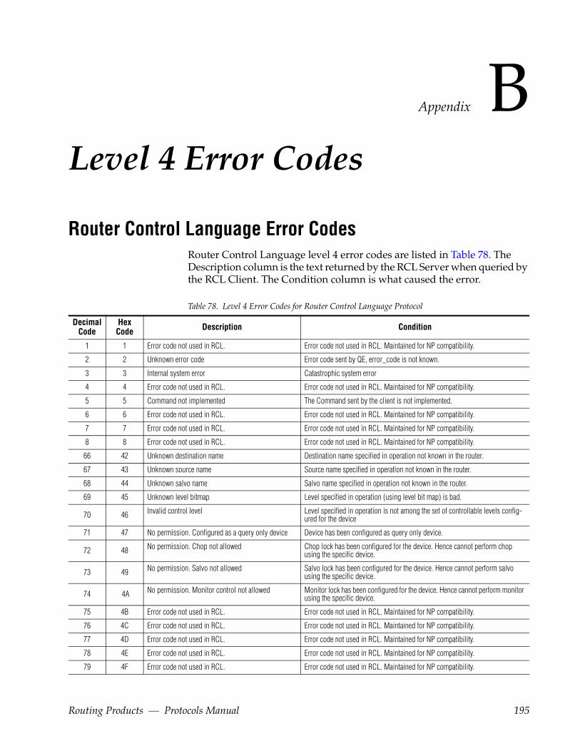
Appendix BLevel 4 Error Codes
Router Control Language Error CodesRouter Control Language level 4 error codes are listed in Table 78. The Description column is the text returned by the RCL Server when queried by the RCL Client. The Condition column is what caused the error.
Table 78. Level 4 Error Codes for Router Control Language Protocol
DecimalCode
HexCode Description Condition
1 1 Error code not used in RCL. Error code not used in RCL. Maintained for NP compatibility.
2 2 Unknown error code Error code sent by QE, error_code is not known.
3 3 Internal system error Catastrophic system error
4 4 Error code not used in RCL. Error code not used in RCL. Maintained for NP compatibility.
5 5 Command not implemented The Command sent by the client is not implemented.
6 6 Error code not used in RCL. Error code not used in RCL. Maintained for NP compatibility.
7 7 Error code not used in RCL. Error code not used in RCL. Maintained for NP compatibility.
8 8 Error code not used in RCL. Error code not used in RCL. Maintained for NP compatibility.
66 42 Unknown destination name Destination name specified in operation not known in the router.
67 43 Unknown source name Source name specified in operation not known in the router.
68 44 Unknown salvo name Salvo name specified in operation not known in the router.
69 45 Unknown level bitmap Level specified in operation (using level bit map) is bad.
70 46 Invalid control level Level specified in operation is not among the set of controllable levels config-ured for the device
71 47 No permission. Configured as a query only device Device has been configured as query only device.
72 48 No permission. Chop not allowed Chop lock has been configured for the device. Hence cannot perform chop using the specific device.
73 49 No permission. Salvo not allowed Salvo lock has been configured for the device. Hence cannot perform salvo using the specific device.
74 4A No permission. Monitor control not allowed Monitor lock has been configured for the device. Hence cannot perform monitor using the specific device.
75 4B Error code not used in RCL. Error code not used in RCL. Maintained for NP compatibility.
76 4C Error code not used in RCL. Error code not used in RCL. Maintained for NP compatibility.
77 4D Error code not used in RCL. Error code not used in RCL. Maintained for NP compatibility.
78 4E Error code not used in RCL. Error code not used in RCL. Maintained for NP compatibility.
79 4F Error code not used in RCL. Error code not used in RCL. Maintained for NP compatibility.
Routing Products — Protocols Manual 195
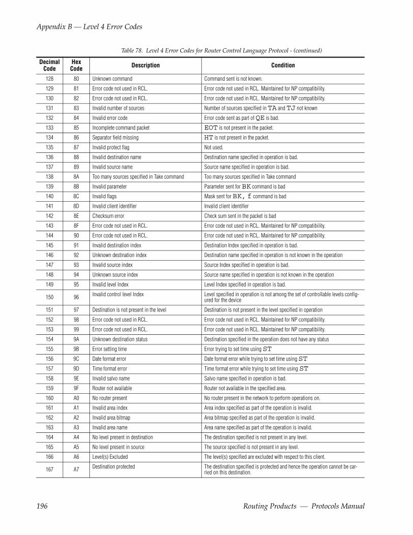
Appendix B — Level 4 Error Codes
128 80 Unknown command Command sent is not known.
129 81 Error code not used in RCL. Error code not used in RCL. Maintained for NP compatibility.
130 82 Error code not used in RCL. Error code not used in RCL. Maintained for NP compatibility.
131 83 Invalid number of sources Number of sources specified in TA and TJ not known
132 84 Invalid error code Error code sent as part of QE is bad.
133 85 Incomplete command packet EOT is not present in the packet.
134 86 Separator field missing HT is not present in the packet.
135 87 Invalid protect flag Not used.
136 88 Invalid destination name Destination name specified in operation is bad.
137 89 Invalid source name Source name specified in operation is bad.
138 8A Too many sources specified in Take command Too many sources specified in Take command
139 8B Invalid parameter Parameter sent for BK command is bad
140 8C Invalid flags Mask sent for BK, f command is bad
141 8D Invalid client identifier Invalid client identifier
142 8E Checksum error Check sum sent in the packet is bad
143 8F Error code not used in RCL. Error code not used in RCL. Maintained for NP compatibility.
144 90 Error code not used in RCL. Error code not used in RCL. Maintained for NP compatibility.
145 91 Invalid destination index Destination Index specified in operation is bad.
146 92 Unknown destination index Destination name specified in operation is not known in the operation
147 93 Invalid source index Source Index specified in operation is bad.
148 94 Unknown source index Source name specified in operation is not known in the operation
149 95 Invalid level Index Level Index specified in operation is bad.
150 96 Invalid control level Index Level specified in operation is not among the set of controllable levels config-ured for the device
151 97 Destination is not present in the level Destination is not present in the level specified in operation
152 98 Error code not used in RCL. Error code not used in RCL. Maintained for NP compatibility.
153 99 Error code not used in RCL. Error code not used in RCL. Maintained for NP compatibility.
154 9A Unknown destination status Destination specified in the operation does not have any status
155 9B Error setting time Error trying to set time using ST156 9C Date format error Date format error while trying to set time using ST157 9D Time format error Time format error while trying to set time using ST158 9E Invalid salvo name Salvo name specified in operation is bad.
159 9F Router not available Router not available in the specified area.
160 A0 No router present No router present in the network to perform operations on.
161 A1 Invalid area index Area index specified as part of the operation is invalid.
162 A2 Invalid area bitmap Area bitmap specified as part of the operation is invalid.
163 A3 Invalid area name Area name specified as part of the operation is invalid.
164 A4 No level present in destination The destination specified is not present in any level.
165 A5 No level present in source The source specified is not present in any level.
166 A6 Level(s) Excluded The level(s) specified are excluded with respect to this client.
167 A7 Destination protected The destination specified is protected and hence the operation cannot be car-ried on this destination.
Table 78. Level 4 Error Codes for Router Control Language Protocol - (continued)
DecimalCode
HexCode Description Condition
196 Routing Products — Protocols Manual
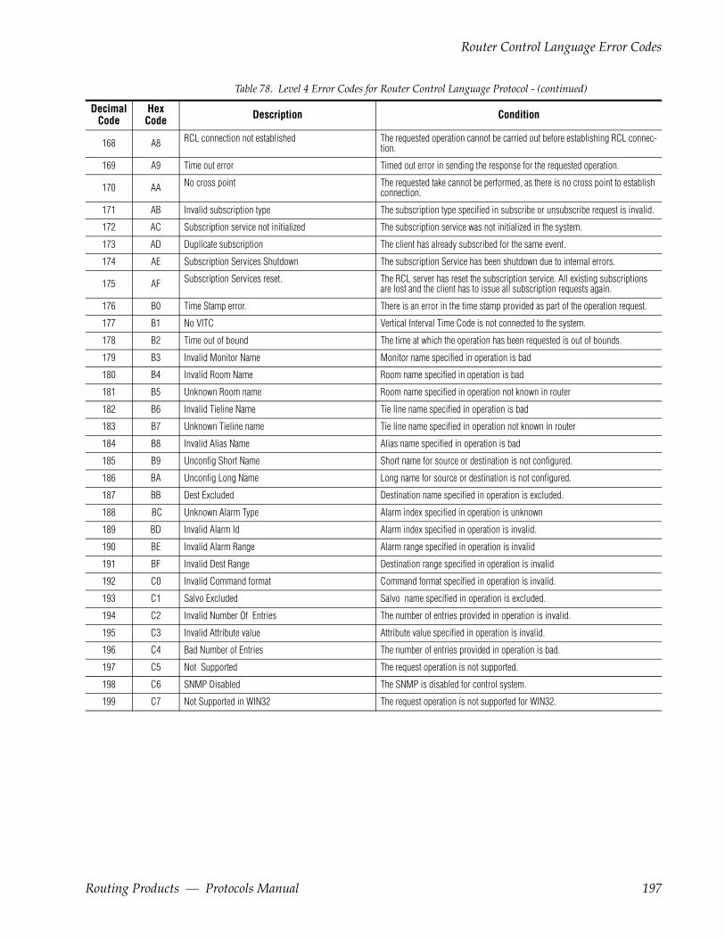
Router Control Language Error Codes
168 A8 RCL connection not established The requested operation cannot be carried out before establishing RCL connec-tion.
169 A9 Time out error Timed out error in sending the response for the requested operation.
170 AA No cross point The requested take cannot be performed, as there is no cross point to establish connection.
171 AB Invalid subscription type The subscription type specified in subscribe or unsubscribe request is invalid.
172 AC Subscription service not initialized The subscription service was not initialized in the system.
173 AD Duplicate subscription The client has already subscribed for the same event.
174 AE Subscription Services Shutdown The subscription Service has been shutdown due to internal errors.
175 AF Subscription Services reset. The RCL server has reset the subscription service. All existing subscriptions are lost and the client has to issue all subscription requests again.
176 B0 Time Stamp error. There is an error in the time stamp provided as part of the operation request.
177 B1 No VITC Vertical Interval Time Code is not connected to the system.
178 B2 Time out of bound The time at which the operation has been requested is out of bounds.
179 B3 Invalid Monitor Name Monitor name specified in operation is bad
180 B4 Invalid Room Name Room name specified in operation is bad
181 B5 Unknown Room name Room name specified in operation not known in router
182 B6 Invalid Tieline Name Tie line name specified in operation is bad
183 B7 Unknown Tieline name Tie line name specified in operation not known in router
184 B8 Invalid Alias Name Alias name specified in operation is bad
185 B9 Unconfig Short Name Short name for source or destination is not configured.
186 BA Unconfig Long Name Long name for source or destination is not configured.
187 BB Dest Excluded Destination name specified in operation is excluded.
188 BC Unknown Alarm Type Alarm index specified in operation is unknown
189 BD Invalid Alarm Id Alarm index specified in operation is invalid.
190 BE Invalid Alarm Range Alarm range specified in operation is invalid
191 BF Invalid Dest Range Destination range specified in operation is invalid
192 C0 Invalid Command format Command format specified in operation is invalid.
193 C1 Salvo Excluded Salvo name specified in operation is excluded.
194 C2 Invalid Number Of Entries The number of entries provided in operation is invalid.
195 C3 Invalid Attribute value Attribute value specified in operation is invalid.
196 C4 Bad Number of Entries The number of entries provided in operation is bad.
197 C5 Not Supported The request operation is not supported.
198 C6 SNMP Disabled The SNMP is disabled for control system.
199 C7 Not Supported in WIN32 The request operation is not supported for WIN32.
Table 78. Level 4 Error Codes for Router Control Language Protocol - (continued)
DecimalCode
HexCode Description Condition
Routing Products — Protocols Manual 197
Appendix B — Level 4 Error Codes
Native Protocol Error Codes
Table 79. Level 4 Error Codes for Native Protocols
Decimal Code
HexCode Meaning Decimal
CodeHexCode Meaning
1 1 Directed Response Error 141 8D Unknown Tag For RCL
2 2 Unknown Error Code 142 8E Chksum Lvl4 Err
3 3 System Error 143 8F Lvl4 Embedded SOH Err
4 4 System Table Error 144 90 Lvl4 Embedded EOT Err
5 5 Not Implemented 145 91 Bad Dst Index
6 6 Semaphore Create Error 146 92 Unknown Dst Index
7 7 Semaphore Give Error 147 93 Bad Src Index
8 8 Semaphore Take Error 148 94 Unknown Src Index
66 42 Unknown Dest Name 149 95 Bad Level Index
67 43 Unknown Source Name 150 96 Invalid Ctl Lvl Index
68 44 Unknown Salvo name 151 97 Level Not In Destination
69 45 Bad Level Bit Map 152 98 Rooms Not Enabled
70 46 Invalid Control Level 153 99 Room Count Is Zero
71 47 Panel Locked 154 9A No Dest Status Exists
72 48 Chop Lock 155 9B Err Trying To Set Time in MCPU
73 49 Salvo Lock 156 9C Date format error
74 4A No Monitor Control 157 9D Time format error
75 4B Send To MCPU Error 158 9E Parse Bad Salvo Name
76 4C Redirect CoProc Msgs Err 188 BC Unknown Alarm Type
77 4D Assignments Not Enabled 189 BD Invalid Alarm Id
78 4E New Net Detected, But Not Active 190 BE Invalid Alarm Range
79 4F Previously Detected Net Now Not Active 191 BF Invalid Dest Range
128 80 Unknown Command 192 C0 Invalid Command format
129 81 CL-CMD Disabled 193 C1 Salvo Excluded
130 82 Bad CL-CMD Syntax 194 C2 Invalid Number Of Entries
131 83 Bad Nbr of Sources 195 C3 Invalid Attribute value
132 84 BadError Code 196 C4 Bad Number of Entries
133 85 Parse EOT missing 197 C5 Not Supported
134 86 Parse HT missing 198 C6 SNMP Disabled
135 87 Parse Bad Protect Flag 199 C7 Not Supported in WIN32
136 88 Parse Bad Dst Name
137 89 Parse Bad Src Name
138 8A Too Many Sources
139 8B Bad Parameter
140 8C Bad Mask
Native Protocol level 4 error codes are listed in Table 79.
198 Routing Products — Protocols Manual
Index
Symbols!E01 Error Code
T/CI 188!E02 Error Code
T/CI 188!E04 Error Code
T/CI 189!E07 Error Code
T/CI 189!E12 Error Code
T/CI 189!E13 Error Code
T/CI 189!E75 Error Code
T/CI 189
AACK
NP 117RCL 23
Alarm Status ChangeNP 158
Area bitmapRCL 29
Areas RCL 32AS Command
NP 132RCL 39
BBGA Command
RCL 45Bitmap
Area RCL 29Level RCL 29
BK CommandNP 133RCL 40
Buffer Sizes
NP 124
CCA Command
RCL 42CH Command
NP 135RCL 43
ChecksumNP 118RCL 24RCL calculation algorithm 27
Client Subscription MessagesNP 132
CM CommandRCL 44
CommandAS, Assign Source
RCL 39AS, Machine Assign
NP 132BK, Background Activities
NP 133RCL 40
CA, Change AliasRCL 42
CH, Request ChopNP 135RCL 43
CM, Commit Alias ChangesRCL 44
Connect (2)SNC 172
Connect On Go (5)SNC 174
Connect_On_Go_Acknowledge (12)SNC 175
Connected (4)SNC 173
CPOT/CI 187
CT, Clear TieLine
Routing Products — Protocols Manual 199
Index
NP 136DA, De-Assign Source
RCL 45DA, Machine De-Assign
NP 136DIN
T/CI 181DPO
T/CI 184GA, Get Alias Name
RCL 45Go (6)
SNC 174Go_Done (13)
SNC 175GT, Get Current VITC Time
RCL 46Interrogate (1)
SNC 172NY, Notification
NP 158RCL 82
PI, Protect by IndexNP 136
PR, ProtectRCL 47
PR, Protect RequestNP 137
QA, Query AssignmentNP 137
QA, Query Machine Assignment StatusRCL 48
QB, Query Alarm DefinitionsNP 138RCL 48
QC, Query Combined Dest StatusNP 139RCL 50
QD, Query DestinationNP 140
Qd, Query DestinationNP 141
QD, Query Destination StatusRCL 51
QE Query ErrorsNP 142
QE, Query Error DefinitionRCL 53
QH Query Alarm StatusNP 142
QH, Query Alarm StatusRCL 53
QI, Query Destination Status on a Specific Level by Index RCL 55
QI, Query IndexNP 143
Qi, Query IndexNP 144
QJ, Query Destination Status by IndexRCL 55
QJ, Query IndexNP 144
Qj, Query IndexNP 146
QK, Query Destination Status,Index, Tie LinesRCL 57
QL, Query TieLine InfoNP 146
Ql, Query TieLine InfoNP 147
QM, Query Monitor StatusRCL 58
Qm, Query Monitors w Level InfoRCL 59
QN, Query NamesNP 149RCL 64
QP, Query Salvo Details, ProtectRCL 59
QR, Query Room DetailsRCL 60
Qs, Query Salvo Element w Op TypeRCL 61
QT, Query Date & TimeNP 152RCL 62
QU, Query Audio AttributesRCL 62
QV, Query SalvoNP 153
QX, Query Cashed Dest Status by IndexRCL 71
QY, Query Cached Dest StatusRCL 71
RC, RCL ConnectRCL 72
RD, RCL DisconnectRCL 72, 83
RN, RCL AnnounceRCL 83
200 Routing Products — Protocols Manual

Index
SA, Set Audio AttributesRCL 73
SB, SubscribeNP 157RCL 81
SPOT/CI 186
ST, Set Date & TimeNP 153
TA, Request TakeNP 153
TA, Take (Breakaway)RCL 75
Tally (3)SNC 173
TD, Request Take DestinationNP 154
TI, Request Take IndexNP 154
TI, Take by Level IndexRCL 77
TINT/CI 180, 184
TJ, Request Take IndexNP 155
TJ, Request Take MonitorNP 155
TJ, Take by Level BitmapRCL 77
TM, Take MonitorRCL 78
TS, Request Take SalvoNP 156
TS, Take SalvoRCL 79
UB, Unsubscribe RequestNP 157RCL 81
UI, Unprotect by IndexNP 156RCL 80
UP, Request Un-ProtectNP 156
UP, Request UnprotectRCL 80
Command CharactersT/CI 178
Command descriptionT/CI 178
Command EchoNP 118
Command PI, Protect by Index 47Configuration change subscriptions RCL 33, 88Connect Command
SNC 172Connect On Go Command
SNC 174Connect sequence RCL 24Connect_On_Go_Acknowledge Command
SNC 175Connected Command
SNC 173CPO Command
T/CI 187CT Command
NP 136
DDA Command
NP 136RCL 45
Destination change subscriptions RCL 85Destination Status Change By Index
NP 160Destination Status Change By Name
NP 162DIN Command
T/CI 181Disconnect RCL 25documentation online 4DPO Command
T/CI 184
EError Code T/CI
!E01 188!E02 188!E04 189!E07 189!E12 189!E13 189!E75 189
Error Format
Routing Products — Protocols Manual 201

Index
NP 122Ethernet
Level 1 NP 116Level 1 RCL 22Level 2, 3, 4 NP 116Level 2, 3, 4 RCL 22
Exclusion sets RCL 34
FFAQ database 4frequently asked questions 4
GG0_Done Command
SNC 175Go Command
SNC 174Grass Valley web site 4GT Command
RCL 46
HHandshaking SNC 167
IInterrogate Command
SNC 172IP Address
NP 113, 117RCL 19
LLevel 1 NP
Ethernet 116RS-232 113
Level 1 RCLEthernet 22RS-232 20
Level 2 NPRS-232 114
Level 2 RCLRS-232 20
Level 2, 3, 4 NPEthernet 116
Level 2, 3, 4 RCLEthernet 22
Level 3 NPRS-232 115
Level 3 RCLRS-232 21
Level 4 NPRS-232 115
Level 4 RCLRS-232 21
Level bitmapRCL 29
Level descriptionsNP 113RCL 19
limitationsT/CI commands 180
Link layer SNCType 02 166Type 02x 166
MMessage Format
NP 119RCL 25SNC type 02 167
Message ID RCL 32
NNAK
NP 117RCL 23
Native ProtocolCommand List 131Format
Error 122Request 119Response 120
Protects 127NP
Client Subscription Messages 132Level descriptions 113Server Originated Messages 132
202 Routing Products — Protocols Manual
Index
NY CommandNP 158RCL 82
Oonline documentation 4
PPacket Pacing SNC 166Parameters
T/CI 179PI Command
NP 136RCL 47
PR CommandNP 137RCL 47
ProtectsMaintaining RCL 34Refreshing RCL 34
QQA Command
NP 137RCL 48
QB CommandNP 138RCL 48
QC CommandNP 139RCL 50
QD CommandNP 140RCL 51
Qd CommandNP 141
QE CommandNP 142RCL 53
QH CommandNP 142RCL 53
QI CommandNP 143
RCL 55Qi Command
NP 144QJ Command
NP 144RCL 55
Qj CommandNP 146
QK CommandRCL 57
QL CommandNP 146
Ql CommandNP 147
QM CommandRCL 58
Qm CommandRCL 59
QN CommandNP 149RCL 64
QP CommandRCL 59
QR CommandRCL 60
Qs CommandRCL 61
QT CommandNP 152RCL 62
QU CommandRCL 62
QV CommandNP 153
QX CommandRCL 71
QY CommandRCL 71
RRC Command
RCL 72RCL
Client originated messages 36Client subscription messages 37Level descriptions 19
Routing Products — Protocols Manual 203

Index
Server originated messages 38RCL connect sequence 24RCL disconnect 25RD Command
RCL 72, 83RN Command
RCL 83RS-232
Level 1 NP 113Level 1 RCL 20Level 2 NP 114Level 2 RCL 20Level 3 NP 115Level 3 RCL 21Level 4 NP 115Level 4 RCL 21
RS-422T/CI 177
RS-485SNC 165
SSA Command
RCL 73SB Command
NP 157RCL 81
Server Originated MessagesNP 132
Session ID RCL 32SIGPIPE NP 116SNC type 02
Command set 171Special protocol characters 167
software download from web 4SOM (0x0FF) SNC 167SPO Command
T/CI 186ST Command
NP 153Status change subscriptions RCL 33, 84Subscription
Configuration change RCL 33, 88Destination status change RCL 85Status change RCL 33, 84
Subscription CommandsNP 158
Subscription for EventsNP 163
TT/CI
limitations 180TA Command
NP 153RCL 75
Tally CommandSNC 173
TCP/IP Stream SocketsNP 113RCL 19
TD CommandNP 154
TI CommandNP 154RCL 77
TimeoutNP 118
TIN CommandT/CI 180, 184
TJ CommandNP 155RCL 77
TM CommandRCL 78
TS CommandNP 156RCL 79
UUB Command
NP 157RCL 81
UI CommandNP 156RCL 80
Unsubscription CommandsNP 158
UP CommandNP 156
204 Routing Products — Protocols Manual

Index
RCL 80
VVariables
T/CI 177
Wweb site documentation 4web site FAQ database 4web site Grass Valley 4web site software download 4
Routing Products — Protocols Manual 205

Index
206 Routing Products — Protocols Manual