routine maintenance and servicing - uamjga/haynes_fiesta.pdf · the maintenance schedule for these...
TRANSCRIPT

1
1595Ford Fiesta Remake
Chapter 1Routine maintenance and servicing
Air cleaner element renewal . . . . . . . . . . . . . . . . . . . . . . . . . . . . . . . 24Automatic transmission fluid level check . . . . . . . . . . . . . . . . . . . . . 20Automatic transmission fluid renewal . . . . . . . . . . . . . . . . . . . . . . . . 26Auxiliary drivebelt check and renewal . . . . . . . . . . . . . . . . . . . . . . . . 4Bodywork, paint and exterior trim check . . . . . . . . . . . . . . . . . . . . . 18Brake check . . . . . . . . . . . . . . . . . . . . . . . . . . . . . . . . . . . . . . . . . . . 14Brake fluid renewal . . . . . . . . . . . . . . . . . . . . . . . . . . . . . . . . . . . . . . 31Coolant renewal . . . . . . . . . . . . . . . . . . . . . . . . . . . . . . . . . . . . . . . . 23Door, tailgate and bonnet check and lubrication . . . . . . . . . . . . . . . 16Driveshaft rubber gaiter and CV joint check . . . . . . . . . . . . . . . . . . . 11Emission control system check . . . . . . . . . . . . . . . . . . . . . . . . . . . . . 25Engine compartment wiring check . . . . . . . . . . . . . . . . . . . . . . . . . . 6Engine oil and filter renewal . . . . . . . . . . . . . . . . . . . . . . . . . . . . . . . 3Exhaust system check . . . . . . . . . . . . . . . . . . . . . . . . . . . . . . . . . . . 12Front wheel alignment check . . . . . . . . . . . . . . . . . . . . . . . . . . . . . . 28Fuel filter renewal . . . . . . . . . . . . . . . . . . . . . . . . . . . . . . . . . . . . . . . 30
Handbrake adjustment . . . . . . . . . . . . . . . . . . . . . . . . . . . . . . . . . . . 27Idle speed and mixture check and adjustment . . . . . . . . . . . . . . . . 9Idle speed control valve cleaning and maintenance . . . . . . . . . . . . . 22Intensive maintenance . . . . . . . . . . . . . . . . . . . . . . . . . . . . . . . . . . . 2Introduction . . . . . . . . . . . . . . . . . . . . . . . . . . . . . . . . . . . . . . . . . . . . 1Manual transmission oil level check . . . . . . . . . . . . . . . . . . . . . . . . . 8Road test . . . . . . . . . . . . . . . . . . . . . . . . . . . . . . . . . . . . . . . . . . . . . . 19Roadwheel nut tightness check . . . . . . . . . . . . . . . . . . . . . . . . . . . . 15Seat belt check . . . . . . . . . . . . . . . . . . . . . . . . . . . . . . . . . . . . . . . . . 17Spark plug renewal and HT component check . . . . . . . . . . . . . . . . . 21Steering, suspension and roadwheel check . . . . . . . . . . . . . . . . . . . 10Timing belt renewal . . . . . . . . . . . . . . . . . . . . . . . . . . . . . . . . . . . . . . 29Underbody and fuel/brake line check . . . . . . . . . . . . . . . . . . . . . . . . 13Underbonnet check for fluid leaks and hose condition . . . . . . . . . . 5Valve clearance adjustment . . . . . . . . . . . . . . . . . . . . . . . . . . . . . . . 7
1•1
Contents
Easy, suitable fornovice with littleexperience
Fairly easy, suitablefor beginner withsome experience
Fairly difficult,suitable for competentDIY mechanic
Difficult, suitable forexperienced DIYmechanic
Very difficult,suitable for expert DIYor professional
Degrees of difficulty
54321

Lubricants and fluidsRefer to end of “Weekly Checks”
Capacities
Engine oilAt oil and filter change:
HCS engines . . . . . . . . . . . . . . . . . . . . . . . . . . . . . . . . . . . . . . . . . . . . 3.25 litresCVH and PTE engines . . . . . . . . . . . . . . . . . . . . . . . . . . . . . . . . . . . . 3.50 litresZetec engines . . . . . . . . . . . . . . . . . . . . . . . . . . . . . . . . . . . . . . . . . . . 4.25 litres
Difference between dipstick minimum and maximum level notches . . . 0.5 to 1.0 litre
Cooling systemHCS engines . . . . . . . . . . . . . . . . . . . . . . . . . . . . . . . . . . . . . . . . . . . . . . 7.1 litresCVH and PTE engines . . . . . . . . . . . . . . . . . . . . . . . . . . . . . . . . . . . . . . 7.6 litresZetec engines . . . . . . . . . . . . . . . . . . . . . . . . . . . . . . . . . . . . . . . . . . . . . 7.0 litres
Fuel tank . . . . . . . . . . . . . . . . . . . . . . . . . . . . . . . . . . . . . . . . . . . . . . . . 42.0 litres
Manual transmission . . . . . . . . . . . . . . . . . . . . . . . . . . . . . . . . . . . . . . 3.1 litres
Automatic transmission . . . . . . . . . . . . . . . . . . . . . . . . . . . . . . . . . . . . 3.5 litres
EngineDirection of crankshaft rotation . . . . . . . . . . . . . . . . . . . . . . . . . . . . . . . Clockwise (seen from right-hand side of vehicle)Oil filter:
HCS, CVH and PTE engines . . . . . . . . . . . . . . . . . . . . . . . . . . . . . . . . Champion C104Zetec engines . . . . . . . . . . . . . . . . . . . . . . . . . . . . . . . . . . . . . . . . . . . Champion C148
Cooling systemCoolant protection at standard 40% antifreeze/water mixture ratio:
Slush point . . . . . . . . . . . . . . . . . . . . . . . . . . . . . . . . . . . . . . . . . . . . . -25ºC (-13ºF)Solidifying point . . . . . . . . . . . . . . . . . . . . . . . . . . . . . . . . . . . . . . . . . -30ºC (-22ºF)
Coolant specific gravity at standard 40% antifreeze/water mixture ratio and 15ºC/59ºF - with no other additives in coolant . . . . . 1.061
Fuel systemIdle speed*:
1.0, 1.1 and 1.3 litre HCS (carburettor) engines . . . . . . . . . . . . . . . . . 750 ± 50 rpm (cooling fan running)1.4 and 1.6 litre CVH (carburettor) engines:
Manual transmission . . . . . . . . . . . . . . . . . . . . . . . . . . . . . . . . . . . . 800 ± 50 rpm (cooling fan running)CTX automatic transmission . . . . . . . . . . . . . . . . . . . . . . . . . . . . . . 850 ± 50 rpm (cooling fan running)
1.6 litre CVH (EFi fuel injection) engines:Idle speed . . . . . . . . . . . . . . . . . . . . . . . . . . . . . . . . . . . . . . . . . . . . 900 ± 50 rpmBase idle speed . . . . . . . . . . . . . . . . . . . . . . . . . . . . . . . . . . . . . . . . 750 ± 50 rpm
Idle mixture CO content*:1.0, 1.1 and 1.3 litre HCS (carburettor) engines . . . . . . . . . . . . . . . . . 1.0 ± 0.5%1.4 litre CVH (carburettor) engines . . . . . . . . . . . . . . . . . . . . . . . . . . . 1.5 ± 0.25%1.6 litre CVH (carburettor) engines . . . . . . . . . . . . . . . . . . . . . . . . . . . 1.5 ± 0.5%1.6 litre CVH (fuel injection) engines:
Non turbo models . . . . . . . . . . . . . . . . . . . . . . . . . . . . . . . . . . . . . . 0.8 ± 0.25%Turbo models . . . . . . . . . . . . . . . . . . . . . . . . . . . . . . . . . . . . . . . . . 1.5 ± 0.25%
*Note: The idle speed and mixture CO content is only adjustable on the engines shown above. On all other engines, it is controlled by the enginemanagement system, and cannot be checked or adjusted without specialised test equipment.Air filter element:
1.0, 1.1 and 1.3 litre HCS engines . . . . . . . . . . . . . . . . . . . . . . . . . . . Champion W1531.4 litre CVH and PTE engines . . . . . . . . . . . . . . . . . . . . . . . . . . . . . . Champion W2261.6 litre CVH (carburettor) engines . . . . . . . . . . . . . . . . . . . . . . . . . . . Champion W2261.6 litre CVH (fuel injection) engines . . . . . . . . . . . . . . . . . . . . . . . . . . Champion U5571.6 and 1.8 litre Zetec engines . . . . . . . . . . . . . . . . . . . . . . . . . . . . . . Champion U612
Fuel filter:HCS, CVH (fuel injection) and PTE engines:
Without quick-release fuel line fittings . . . . . . . . . . . . . . . . . . . . . . Champion L204With quick-release fuel line fittings . . . . . . . . . . . . . . . . . . . . . . . . . Champion type not available
Zetec engines . . . . . . . . . . . . . . . . . . . . . . . . . . . . . . . . . . . . . . . . . . . Champion L218
1•2 Servicing Specifications
1595Ford Fiesta Remake

Ignition systemFiring order:
HCS engines . . . . . . . . . . . . . . . . . . . . . . . . . . . . . . . . . . . . . . . . . . . . 1-2-4-3 (No 1 cylinder at timing chain end of engine)All other engines . . . . . . . . . . . . . . . . . . . . . . . . . . . . . . . . . . . . . . . . . 1-3-4-2 (No 1 cylinder at timing belt end of engine)
Spark plugs*:HCS engines . . . . . . . . . . . . . . . . . . . . . . . . . . . . . . . . . . . . . . . . . . . . Champion RS9YCC or RS9YC1.4 and 1.6 litre CVH (carburettor) engines . . . . . . . . . . . . . . . . . . . . Champion RC7YCC or RC7YC1.6 litre CVH (EFi fuel injection) and PTE engines
Non-turbo models . . . . . . . . . . . . . . . . . . . . . . . . . . . . . . . . . . . . . . Champion RC7YCC4 or RC7YC4Turbo models . . . . . . . . . . . . . . . . . . . . . . . . . . . . . . . . . . . . . . . . . Champion C61YC
1.6 and 1.8 litre Zetec engines . . . . . . . . . . . . . . . . . . . . . . . . . . . . . . Champion RE7YCCElectrode gap*:
HCS engines . . . . . . . . . . . . . . . . . . . . . . . . . . . . . . . . . . . . . . . . . . . . 1.0 mm1.4 litre CVH (carburettor) engines . . . . . . . . . . . . . . . . . . . . . . . . . . . 0.8 mm1.4 litre CVH (CFi fuel injection) and PTE engine . . . . . . . . . . . . . . . . 1.0 mm1.6 litre CVH (carburettor) engines:
With Champion RC7YCC . . . . . . . . . . . . . . . . . . . . . . . . . . . . . . . . 0.8 mmWith Champion RC7YC . . . . . . . . . . . . . . . . . . . . . . . . . . . . . . . . . 0.7 mm
1.6 litre CVH (EFi fuel injection) engines:Non-turbo models . . . . . . . . . . . . . . . . . . . . . . . . . . . . . . . . . . . . . . 1.0 mmTurbo models . . . . . . . . . . . . . . . . . . . . . . . . . . . . . . . . . . . . . . . . . 0.7 mm
1.6 and 1.8 litre Zetec engines . . . . . . . . . . . . . . . . . . . . . . . . . . . . . . 1.3 mmSpark plug (HT) leads:
HCS engines . . . . . . . . . . . . . . . . . . . . . . . . . . . . . . . . . . . . . . . . . . . . Champion LS-281.4 and 1.6 litre CVH (carburettor) engines . . . . . . . . . . . . . . . . . . . . Champion LS-141.4 litre CVH (CFi fuel injection) and PTE engines . . . . . . . . . . . . . . . Champion LS-141.6 litre CVH (EFi fuel injection) engines . . . . . . . . . . . . . . . . . . . . . . . Champion LS-261.6 and 1.8 litre Zetec engines . . . . . . . . . . . . . . . . . . . . . . . . . . . . . . Champion type not available
Maximum resistance per lead . . . . . . . . . . . . . . . . . . . . . . . . . . . . . . . . 30 000 ohms* Information on spark plug types and electrode gaps is as recommended by Champion Spark Plug. Where alternative types are used, refer to theirmanufacturer’s recommendations.
Braking systemMinimum front brake pad lining thickness . . . . . . . . . . . . . . . . . . . . . . . 1.5 mmMinimum rear brake shoe lining thickness . . . . . . . . . . . . . . . . . . . . . . . 1.0 mm
TyresTyre pressures . . . . . . . . . . . . . . . . . . . . . . . . . . . . . . . . . . . . . . . . . . . . See “Weekly Checks”
Wiper bladesWindscreen . . . . . . . . . . . . . . . . . . . . . . . . . . . . . . . . . . . . . . . . . . . . . . . Champion X-4803Tailgate/rear window . . . . . . . . . . . . . . . . . . . . . . . . . . . . . . . . . . . . . . . Champion X-4103
Torque wrench settings Nm lbf ft
Auxiliary drivebelt cover fasteners . . . . . . . . . . . . . . . . . . . . . . . . . . . . . 8 6Auxiliary drivebelt adjustment:
Adjusting bolt (sliding arm) . . . . . . . . . . . . . . . . . . . . . . . . . . . . . . . . . 22 16Central (locking) bolt . . . . . . . . . . . . . . . . . . . . . . . . . . . . . . . . . . . . . . 22 16Pinion (adjuster) nut . . . . . . . . . . . . . . . . . . . . . . . . . . . . . . . . . . . . . . 12 9Alternator mounting bolts . . . . . . . . . . . . . . . . . . . . . . . . . . . . . . . . . . 24 18Tensioner pulley centre bolt (HCS engines) . . . . . . . . . . . . . . . . . . . . 20 15
Engine oil drain plug . . . . . . . . . . . . . . . . . . . . . . . . . . . . . . . . . . . . . . . . 24 18Manual transmission filler/level plug . . . . . . . . . . . . . . . . . . . . . . . . . . . . 20 15Spark plugs:
HCS engines . . . . . . . . . . . . . . . . . . . . . . . . . . . . . . . . . . . . . . . . . . . . 18 13CVH and PTE engines . . . . . . . . . . . . . . . . . . . . . . . . . . . . . . . . . . . . 24 18Zetec engines . . . . . . . . . . . . . . . . . . . . . . . . . . . . . . . . . . . . . . . . . . . 15 11
Roadwheel nuts . . . . . . . . . . . . . . . . . . . . . . . . . . . . . . . . . . . . . . . . . . . 71 to 100 52 to 74
Servicing Specifications 1•3
1
1595Ford Fiesta Remake

The maintenance schedule for thesevehicles, based on the manufacturer’srecommendations, is as described below -note that the schedule starts from thevehicle’s date of registration. These are theminimum maintenance intervals recommen-ded by the factory for Fiestas driven daily, butsubjected only to “normal” use. If you wish tokeep your vehicle in peak condition at alltimes, you may wish to perform some of theseprocedures even more often. Becausefrequent maintenance enhances theefficiency, performance and resale value ofyour vehicle, we encourage you to do so. Ifyour usage is not “normal”, shorter intervals
are also recommended - the most importantexamples of these are noted in the schedule.These shorter intervals apply particularly ifyou drive in dusty areas, tow a caravan ortrailer, sit with the engine idling or drive at lowspeeds for extended periods (ie, in heavytraffic), or drive for short distances (less than four miles) in below-freezingtemperatures.
When your vehicle is new, it should beserviced by a Ford dealer service departmentto protect the factory warranty. In manycases, the initial maintenance check is doneat no cost to the owner. Note that this firstfree service (carried out by the selling dealer
1500 miles or 3 months after delivery),although an important check for a newvehicle, is not part of the regular maintenanceschedule, and is therefore not mentionedhere.
It should be noted that for the 1992 modelyear, for all models except RS Turbo, theservice time/mileage intervals wereextended by the manufacturer to the periodsshown in this schedule. Although theseintervals can be applied retrospectively,owners of earlier vehicles may notice adiscrepancy between this schedule and theone shown in the Service Guide suppliedwith the vehicle.
1•4 Maintenance schedule
1595Ford Fiesta Remake
Every 250 miles (400 km) or weeklymm Refer to “Weekly Checks”.
Every 5000 miles (8000 km) or 6 months, whichever occurs firstNote: Frequent oil and filter changes are good for the engine. Werecommend changing the oil at the mileage specified here, or at leasttwice a year if the mileage covered is less.mm Renew the engine oil and filter (Section 3).
Every 10 000 miles (16 000 km) or12 months, whichever occurs firstCarry out all operations listed above, plus the following:mm Check the auxiliary drivebelt (Section 4).mm Check under the bonnet for fluid leaks and hose condition
(Section 5).mm Check the condition of all engine compartment wiring (Sec-
tion 6).mm Check the valve clearance adjustment - HCS engines only
(Section 7).mm Check the manual transmission oil level (Section 8).mm Check the engine idle speed and mixture - HCS and CVH
engines only, where possible (Section 9).mm Check the steering, suspension and roadwheels (Section 10).mm Check the driveshaft rubber gaiters and CV joints (Section 11).mm Check the exhaust system (Section 12).mm Check the underbody, and all fuel/brake lines (Section 13).mm Check the brake system (Section 14).mm Check the security of all roadwheel nuts (Section 15).mm Check the doors, tailgate and bonnet, and lubricate their hinges
and locks (Section 16).mm Check the seat belts (Section 17).mm Check the condition of the bodywork, paint and exterior trim
(Section 18).mm Road test (Section 19).mm Check the automatic transmission fluid level (Section 20).
Every 20 000 miles (32 000 km) ortwo years, whichever occurs firstCarry out all operations listed above, plus the following:mm Renew the spark plugs and check the condition of the HT leads
- all engines except Zetec (Section 21).mm Clean the idle speed control valve (Weber type) - CVH EFi
engines only (Section 22).
Every 30 000 miles (48 000 km) orthree years, whichever occurs firstCarry out all operations listed above, plus the following:mm Renew the coolant (Section 23).mm Renew the air cleaner filter element and check the air cleaner
temperature control system - carburettor engines only (Sec-tion 24).
mm Check the emission control systems (Section 25).mm Renew the spark plugs and check the condition of the HT leads
- Zetec engines (Section 21).mm Renew the automatic transmission fluid (Section 26).mm Check the handbrake adjustment (Section 27).mm Check the front wheel alignment (Section 28).Note: If the vehicle is used regularly in dusty or polluted conditions,the air cleaner filter element should be renewed at more frequentintervals.
Every 40 000 milesmm Renew the timing belt - CVH and PTE engines only (Section 29).
Every 60 000 milesmm Renew the timing belt - Zetec engines only (Section 29).mm Renew the fuel filter (Section 30).
Every three years (regardless of mileage)mm Renew the brake fluid (Section 31).
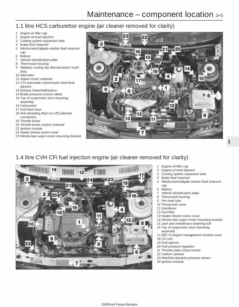
Maintenance – component location 1•5
1 Engine oil filler cap2 Engine oil level dipstick3 Cooling system expansion tank4 Brake fluid reservoir5 Windscreen/tailgate washer fluid reservoir
cap6 Battery7 Vehicle identification plate8 Thermostat housing9 Pre-heat tube10 Timing belt cover11 Distributor12 Fuel filter13 Heater blower motor cover14 Windscreen wiper motor mounting bracket15 Jack and wheelbrace retaining bolt16 Top of suspension strut mounting
assembly17 EEC IV engine management module cover18 CFi unit19 Fuel injector20 Fuel pressure regulator21 Throttle plate control motor22 Carbon canister23 Manifold absolute pressure sensor24 Ignition module
1.1 litre HCS carburettor engine (air cleaner removed for clarity)
1
1595Ford Fiesta Remake
1.4 litre CVH CFi fuel injection engine (air cleaner removed for clarity)
1 Engine oil filler cap2 Engine oil level dipstick3 Cooling system expansion tank4 Brake fluid reservoir5 Windscreen/tailgate washer fluid reservoir
cap6 Battery7 Vehicle identification plate8 Thermostat housing9 Radiator cooling fan thermal switch multi-
plug10 Alternator11 Starter motor solenoid12 CTX automatic transmission fluid level
dipstick13 Exhaust heatshield/airbox14 Brake pressure control valves15 Top of suspension strut mounting
assembly16 Carburettor17 Fuel feed hose18 Anti-dieselling (fuel-cut off) solenoid
connection19 Throttle kicker20 Throttle kicker control solenoid21 Ignition module22 Heater blower motor cover23 Windscreen wiper motor mounting bracket

1•6 Maintenance – component location1.6 litre (XR2i) CVH EFi fuel injection engine
1595Ford Fiesta Remake
1 Engine oil filler cap2 Engine oil level dipstick3 Cooling system expansion tank4 Brake fluid reservoir5 Windscreen/tailgate washer fluid reservoir
cap6 Battery7 Vehicle identification plate8 Thermostat housing9 Timing belt cover10 Top of suspension strut mounting
assembly11 Windscreen wiper motor mounting bracket12 Jack and wheelbrace retaining bolt13 Distributorless (E-DIS) ignition coil14 Fuel filter15 Air cleaner16 Air inlet duct17 Idle speed control valve18 Fuel pressure regulator19 Throttle housing20 Upper section of inlet manifold21 Intake air temperature sensor22 Fuel trap23 EEC IV engine management module cover24 Manifold absolute pressure sensor25 Ignition module
1.8 litre (XR2i) Zetec SEFi fuel injection engine
1 Engine oil filler cap2 Engine oil level dipstick3 Cooling system expansion tank4 Braking system fluid reservoir5 Windscreen/tailgate washer fluid reservoir
cap6 Battery7 VIN plate8 Thermostat housing9 Timing belt cover10 Top of suspension strut mounting
assembly11 Windscreen wiper motor mounting bracket12 Jack and wheelbrace retaining bolt13 Distributorless (E-DIS) ignition coil14 Fuel filter15 Air cleaner16 Air inlet duct17 Idle speed control valve18 Fuel pressure regulator19 Throttle housing20 Inlet manifold21 Throttle position sensor22 Fuel system pressure release/test point23 EEC IV engine management module cover24 Mass air flow sensor25 Ignition module

Maintenance – component location 1•7
1
1595Ford Fiesta Remake
Front underside view of the 1.4 litre CVH CFi fuel injection model
1 Engine oil sump2 Front suspension lower arm3 Brake caliper assembly4 Driveshaft5 Alternator6 Auxiliary drivebelt cover7 Steering rack gaiter8 Windscreen/tailgate washer pump9 Carbon canister10 Oxygen sensor11 Catalytic converter (exhaust) rubber
insulator mounting12 Catalytic converter assembly13 Underbody heatshields14 Gearchange mechanism shift rod15 Gearchange mechanism stabiliser bar
Front underside view of the 1.8 litre (XR2i) Zetec SEFi fuel injection model
1 Engine oil drain plug2 Front suspension lower arm3 Brake caliper assembly4 Driveshaft5 Alternator6 Auxiliary drivebelt cover7 Horn8 Windscreen/tailgate washer pump9 Carbon canister10 Oxygen sensor11 Front suspension crossmember12 Catalytic converter13 Underbody heat shields14 Gearchange mechanism shift rod15 Gearchange mechanism stabiliser bar

1•8 Maintenance – component location
1595Ford Fiesta Remake
Rear underside view of the 1.4 litre CVH CFi fuel injection model
1 Fuel tank2 Fuel filler pipe3 Fuel tank ventilation hose4 Twist beam rear axle assembly5 Underbody heatshields6 Exhaust rear silencer7 Exhaust rubber insulator mounting8 Load apportioning valves (on vehicles with
the anti-lock braking system)9 Handbrake cable10 Rear towing eye11 Spare wheel carrier hook (on the retaining
bolt)
Rear underside view of the Courier van model
1 Fuel tank2 Fuel filler pipe3 Fuel tank ventilation hose4 Rear axle assembly - spring torsion bars
visible5 Rear axle pivot brackets6 Rear suspension dampers7 Exhaust system rear silencer8 Braking system light-laden valve9 Handbrake cables10 Rear towing eye11 Spare wheel carrier

3 Engine oil and filter renewal 1
1 Make sure that you have all the necessarytools before you begin this procedure (seeillustration). You should also have plenty ofrags or newspapers handy, for mopping upany spills.2 To avoid any possibility of scalding, and toprotect yourself from possible skin irritantsand other harmful contaminants in usedengine oils, it is advisable to wear gloveswhen carrying out this work.
3 Access to the underside of the vehicle isgreatly improved if the vehicle can be lifted on ahoist, driven onto ramps, or supported by axlestands (see “Jacking and Vehicle Support”).
Warning: Do not work under avehicle which is supported onlyby an hydraulic or scissors-typejack, or by bricks, blocks ofwood, etc.
4 If this is your first oil change, get under thevehicle and familiarise yourself with theposition of the engine oil drain plug location inthe sump. The engine and exhaustcomponents will be warm during the actualwork, so try to anticipate any potentialproblems while the engine and accessoriesare cool.5 The oil should preferably be changed whenthe engine is still fully warmed-up to normaloperating temperature, just after a run (theneedle on the temperature gauge should be inthe “Normal” sector of the gauge); warm oiland sludge will flow out more easily. Park thevehicle on firm, level ground, apply thehandbrake firmly, then select 1st or reversegear (manual transmission) or the “P” position(automatic transmission). Open the bonnetand remove the engine oil filler cap from thecylinder head cover, then remove the oil leveldipstick from its tube (see “Weekly Checks”).6 Raise the front of the vehicle, and support itsecurely on axle stands (see “Jacking andVehicle Support”). Remove the front right-hand roadwheel to provide access to the oil
1 Introduction
This Chapter is designed to help the homemechanic maintain his/her vehicle for safety,economy, long life and peak performance.
This Chapter contains a mastermaintenance schedule, followed by Sectionsdealing specifically with each task in theschedule. Visual checks, adjustments,component renewal and other helpful itemsare included. Refer to the accompanyingillustrations of the engine compartment andthe underside of the vehicle for the locationsof the various components.
Servicing your vehicle in accordance withthe mileage/time maintenance schedule andthe following Sections will provide a plannedmaintenance programme, which should resultin a long and reliable service life. This is acomprehensive plan, so maintaining someitems but not others at the specified serviceintervals will not produce the same results.
As you service your vehicle, you willdiscover that many of the procedures can -and should - be grouped together, because ofthe particular procedure being performed, orbecause of the close proximity of twootherwise-unrelated components to oneanother. For example, if the vehicle is raisedfor any reason, the exhaust should beinspected at the same time as the suspensionand steering components.
The first step of this maintenanceprogramme is to prepare yourself before theactual work begins. Read through all the
Sections relevant to the work to be carriedout, then make a list and gather together allthe parts and tools required. If a problem isencountered, seek advice from a partsspecialist or a dealer service department.
2 Intensive maintenance
1 If, from the time the vehicle is new, theroutine maintenance schedule is followedclosely, and frequent checks are made of fluidlevels and high-wear items, as suggestedthroughout this manual, the engine will bekept in relatively good running condition, andthe need for additional work will be minimised.2 It is possible that there will be some timeswhen the engine is running poorly due to thelack of regular maintenance. This is even morelikely if a used vehicle, which has not receivedregular and frequent maintenance checks, ispurchased. In such cases, additional workmay need to be carried out, outside of theregular maintenance intervals.3 If engine wear is suspected, a compressiontest (refer to Part A, B or C of Chapter 2) willprovide valuable information regarding theoverall performance of the main internalcomponents. Such a test can be used as abasis to decide on the extent of the work tobe carried out. If, for example, a compressiontest indicates serious internal engine wear,conventional maintenance as described in thisChapter will not greatly improve theperformance of the engine, and may prove a
waste of time and money, unless extensiveoverhaul work (Chapter 2D) is carried out first.4 The following series of operations are thoseoften required to improve the performance ofa generally poor-running engine:
Primary operationsa) Clean, inspect and test the battery (See
“Weekly Checks”).b) Check all the engine-related fluids (See
“Weekly Checks”).c) Check the condition of the auxiliary
drivebelt (Section 4).d) Check and if necessary adjust the valve
clearances on HCS engines (Section 7).e) Renew the spark plugs and clean and
inspect the HT leads (Section 21).f) Check the condition of the air cleaner
filter element and renew if necessary(Section 24).
g) Check and if necessary adjust the idlespeed and mixture settings - whereapplicable (Section 9).
h) Renew the fuel filter - fuel injectionmodels (Section 30).
i) Check the condition of all hoses, andcheck for fluid leaks (Section 5).
5 If the above operations do not prove fullyeffective, carry out the following operations:
Secondary operationsAll the items listed under “Primaryoperations”, plus the following:a) Check the charging system (Chapter 5A).b) Check the ignition system (Chapter 5B).c) Check the fuel system (Chapter 4A, 4B,
4C and 4D).e) Renew the ignition HT leads (Section 21).
Maintenance procedures 1•9
3.2 These tools are required whenchanging the engine oil and filter
1
1595Ford Fiesta Remake
Every 5000 miles (8000 km) or 6 months, whichever occurs first
Frequent oil changes are thebest preventivemaintenance the homemechanic can give the
engine, because ageing oil becomesdiluted and contaminated, which leadsto premature engine wear.

filter; if the additional working clearance isrequired, remove also the auxiliary drivebeltcover.7 Being careful not to touch the hot exhaustcomponents, place the drain pan under thedrain plug, and unscrew the plug (seeillustrations). If possible, try to keep the plugpressed into the sump while unscrewing it byhand the last couple of turns.
8 Allow some time for the old oil to drain,noting that it may be necessary to repositionthe pan as the oil flow slows to a trickle.Check the condition of the plug’s sealingwasher and renew it if worn or damaged.When the oil has completely drained, wipeclean the drain plug and its threads in thesump and refit the plug, tightening it to thespecified torque wrench setting.9 Reposition the drain pan under the oil filterthen, using a suitable filter removal tool,
unscrew the oil filter from the cylinder block,oil pump or oil filter adaptor, as applicable; beprepared for some oil spillage (seeillustration). Check the old filter to make surethat the rubber sealing ring hasn’t stuck to theengine; if it has, carefully remove it. Withdrawthe filter through the wheel arch, taking careto spill as little oil as possible.10 Using a clean, lint-free rag, wipe clean thecylinder block around the filter mounting. Ifthere are no specific instructions suppliedwith it, fit a new oil filter as follows. Apply alight coating of clean engine oil to the filter’ssealing ring (see illustration). Screw the filterinto position until it seats, then tighten itthrough a further half- to three-quarters of aturn only (see illustration). Tighten the filterby hand only - do not use any tools.11 Remove the old oil and all tools fromunder the vehicle, refit the roadwheel, andlower the vehicle to the ground.12 Refill the engine with oil, using the correctgrade and type of oil, as given in “Lubricants,fluids and tyre pressures”. Pour in half thespecified quantity of oil first, then wait a fewminutes for the oil to run to the sump.Continue adding oil a small quantity at a time,until the level is up to the lower notch on the
dipstick. Adding approximately 0.5 to 1.0 litre(depending on model) will raise the level to thedipstick’s upper notch.13 Start the engine. The oil pressure warninglight will take a few seconds to go out whilethe new filter fills with oil; do not race theengine while the light is on. Run the engine fora few minutes, while checking for leaksaround the oil filter seal and the drain plug.14 Switch off the engine, and wait a fewminutes for the oil to settle in the sump oncemore. With the new oil circulated and the filternow completely full, recheck the level on thedipstick, and add more oil as necessary.15 Dispose of the used engine oil safely, withreference to “General repair procedures” inthe Reference Sections of this manual.
1•10 Every 5000 miles or 6 months
3.10b Fitting the new oil filter on the Zetec engine 3.10a Lubricate the filter’s sealing ring with clean engine oilbefore installing the filter on the engine
3.9 Removing the oil filter on the CVHengine using a strap wrench
3.7b Removing the engine oil drain plugon the Zetec engine
3.7a Engine oil drain plug location in thesump on HCS, CVH and PTE engines
1595Ford Fiesta Remake
Note: It isantisocial andillegal to dump oildown the drain.To find thelocation of yourlocal oil recyclingbank, call thisnumber free.
As the drain plug releasesfrom the threads, move itaway sharply, so the streamof oil issuing from the sumpruns into the pan, not upyour sleeve!
4 Auxiliary drivebelt check andrenewal 2
General1 The number of auxiliary drivebelts fitted andtheir type depends on engine, and on whetherthe vehicle is equipped with power steering.The drivebelt(s) are located on the right-handend of the engine and will be either of the V-belt type or the flat, multi-ribbed (or “polyvee”)type. The belt drives the alternator, waterpump and, on CVH and Zetec engines withpower steering, the power steering pumpfrom the engine’s crankshaft pulley. On HCSengines with power steering, one belt drivesthe alternator and water pump and a separatebelt drives the power steering pump.2 The good condition and proper tension ofthe auxiliary drivebelt is critical to theoperation of the engine. Because of theircomposition and the high stresses to whichthey are subjected, drivebelts stretch anddeteriorate as they get older. They must,therefore, be regularly inspected.
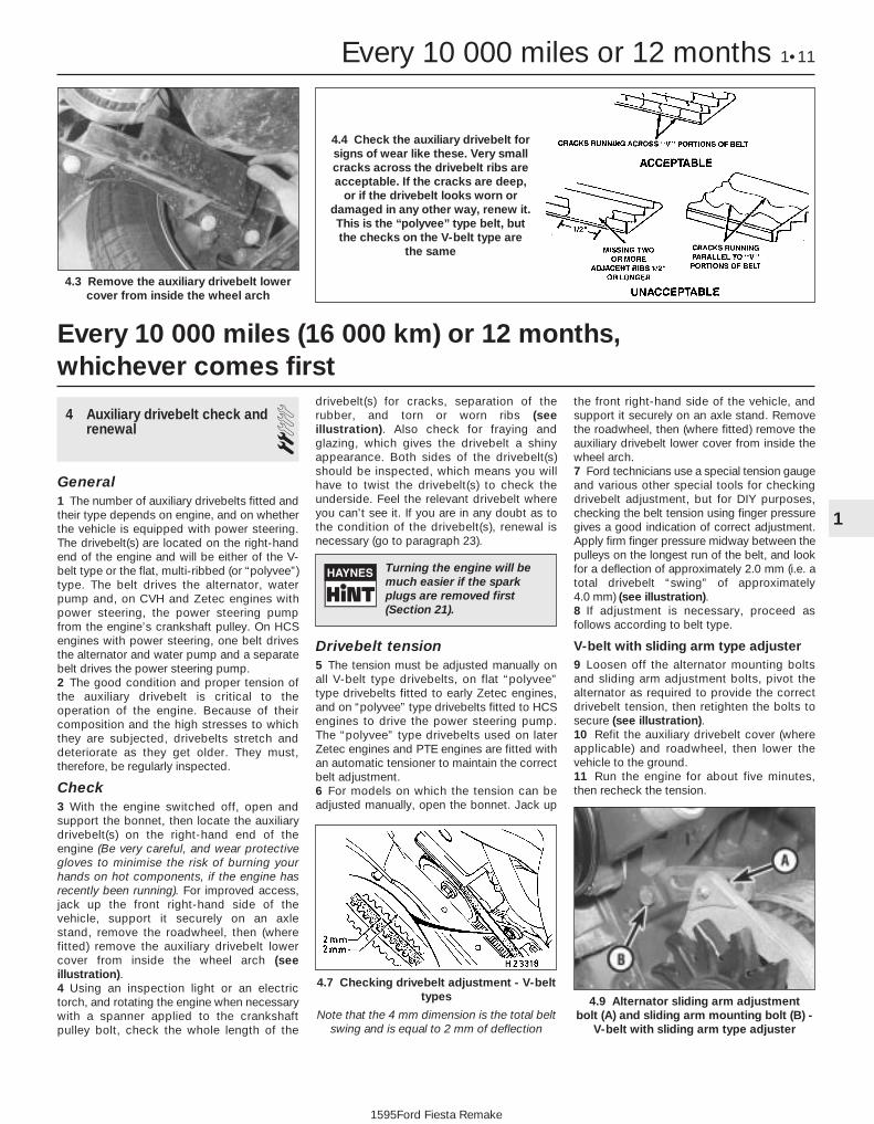
Check3 With the engine switched off, open andsupport the bonnet, then locate the auxiliarydrivebelt(s) on the right-hand end of theengine (Be very careful, and wear protectivegloves to minimise the risk of burning yourhands on hot components, if the engine hasrecently been running). For improved access,jack up the front right-hand side of thevehicle, support it securely on an axle stand, remove the roadwheel, then (wherefitted) remove the auxiliary drivebelt lowercover from inside the wheel arch (seeillustration).4 Using an inspection light or an electrictorch, and rotating the engine when necessarywith a spanner applied to the crankshaftpulley bolt, check the whole length of the
drivebelt(s) for cracks, separation of therubber, and torn or worn ribs (seeillustration). Also check for fraying andglazing, which gives the drivebelt a shinyappearance. Both sides of the drivebelt(s)should be inspected, which means you willhave to twist the drivebelt(s) to check theunderside. Feel the relevant drivebelt whereyou can’t see it. If you are in any doubt as tothe condition of the drivebelt(s), renewal isnecessary (go to paragraph 23).
Drivebelt tension5 The tension must be adjusted manually onall V-belt type drivebelts, on flat “polyvee”type drivebelts fitted to early Zetec engines,and on “polyvee” type drivebelts fitted to HCSengines to drive the power steering pump.The “polyvee” type drivebelts used on laterZetec engines and PTE engines are fitted withan automatic tensioner to maintain the correctbelt adjustment.6 For models on which the tension can beadjusted manually, open the bonnet. Jack up
the front right-hand side of the vehicle, andsupport it securely on an axle stand. Removethe roadwheel, then (where fitted) remove theauxiliary drivebelt lower cover from inside thewheel arch.7 Ford technicians use a special tension gaugeand various other special tools for checkingdrivebelt adjustment, but for DIY purposes,checking the belt tension using finger pressuregives a good indication of correct adjustment.Apply firm finger pressure midway between thepulleys on the longest run of the belt, and lookfor a deflection of approximately 2.0 mm (i.e. atotal drivebelt “swing” of approximately 4.0 mm) (see illustration).8 If adjustment is necessary, proceed asfollows according to belt type.
V-belt with sliding arm type adjuster9 Loosen off the alternator mounting boltsand sliding arm adjustment bolts, pivot thealternator as required to provide the correctdrivebelt tension, then retighten the bolts tosecure (see illustration).10 Refit the auxiliary drivebelt cover (whereapplicable) and roadwheel, then lower thevehicle to the ground.11 Run the engine for about five minutes,then recheck the tension.
Every 10 000 miles (16 000 km) or 12 months, whichever comes first
Every 10 000 miles or 12 months 1•11
4.9 Alternator sliding arm adjustment bolt (A) and sliding arm mounting bolt (B) -
V-belt with sliding arm type adjuster
4.7 Checking drivebelt adjustment - V-belttypes
Note that the 4 mm dimension is the total beltswing and is equal to 2 mm of deflection
4.3 Remove the auxiliary drivebelt lowercover from inside the wheel arch
1
1595Ford Fiesta Remake
4.4 Check the auxiliary drivebelt forsigns of wear like these. Very smallcracks across the drivebelt ribs areacceptable. If the cracks are deep,
or if the drivebelt looks worn ordamaged in any other way, renew it.This is the “polyvee” type belt, butthe checks on the V-belt type are
the same
Turning the engine will bemuch easier if the sparkplugs are removed first(Section 21).

V-belt and flat “polyvee” typedrivebelt with rack-and-pinion typeadjuster12 Loosen off the alternator mounting boltsand the adjusting arm mounting bolt. Slackenthe pinion central locking bolt, and turn thepinion nut as required to take up the tensionof the drivebelt. Hold it at the required setting,and tighten the central bolt securely to lockthe adjuster arm and set the tension (seeillustrations).13 Tighten the alternator mounting andadjusting arm bolts securely.14 Refit the auxiliary drivebelt cover (whereapplicable) and roadwheel, then lower thevehicle to the ground.15 Run the engine for about five minutes,then recheck the tension.
Flat “polyvee” type drivebelt withtensioner pulley adjuster (HCS enginepower steering pump drivebelt)16 Slacken the tensioner pulley centre boltthen turn the adjuster bolt at the base of thetensioner pulley bracket, as required, to takeup the tension of the drivebelt. When the beltdeflection is correct, tighten the adjusterpulley centre retaining bolt.17 Refit the auxiliary drivebelt cover (whereapplicable) and roadwheel, then lower thevehicle to the ground.18 Run the engine for about five minutes,then recheck the tension.
Flat “polyvee” type drivebelt withautomatic adjuster19 As mentioned above, this type of drivebeltis tensioned by an automatic tensioner;regular checks are not required, and manual“adjustment” is not possible.20 If you suspect that the drivebelt is slippingand/or running slack, or that the tensioner isotherwise faulty, it must be renewed. To dothis, remove the drivebelt as described below,then unbolt and remove the tensioner. Onfitting the new tensioner, ensure that it isaligned correctly on its mountings, andtightened to the specified torque wrenchsetting.
Renewal21 Open the bonnet. Jack up the front right-hand side of the vehicle, and support itsecurely on an axle stand. Remove theroadwheel, then remove the auxiliary drivebeltlower cover (where fitted) from inside thewheel arch.22 The routing of the drivebelt around thepulleys is dependent on the drivebelt type,and on whether power steering is fitted.Before removing the drivebelt, it’s a good ideato sketch the belt run around the pulleys; thiswill save a lot of frustration when it comes torefitting. Note that on HCS engines withpower steering, to renew the alternator/water pump drivebelt it will be necessary toremove the power steering pump drivebeltfirst.23 If the existing drivebelt is to be refitted,mark it, or note the maker’s markings on itsflat surface, so that it can be installed thesame way round.24 To renew a drivebelt with manualadjustment, slacken the belt tension fully asdescribed above, according to type. Slip thebelt off the pulleys, then fit the new belt,ensuring that it is routed correctly. If fitting aflat “polyvee” type drivebelt, arrange it on thegrooved pulleys so that it is centred in their grooves, and not overlapping their raisedsides. With the belt in position, adjust thetension as previously described.25 To renew the flat, “polyvee” type drivebeltwith automatic adjuster, reach up betweenthe body and the engine (above thecrankshaft pulley), and apply a spanner to thehexagon in the centre of the automatictensioner’s pulley. Rotate the tensioner pulleyclockwise to release its pressure on thedrivebelt, then slip the drivebelt off thecrankshaft pulley, and release the tensioneragain (see illustration). Note that on certainmodels, a self-cocking tensioner is fitted, andthat this will remain in the released position.Working from the wheel arch or enginecompartment as necessary, and noting itsrouting, slip the drivebelt off the remainingpulleys and withdraw it.26 Check all the pulleys, ensuring that theirgrooves are clean, and removing all traces of
oil and grease. Check that the tensionerworks properly, with strong spring pressurebeing felt when its pulley is rotated clockwise,and a smooth return to the limit of its travelwhen released.27 If the original drivebelt is being refitted,use the marks or notes made on removal, toensure that it is installed to run in the samedirection as it was previously. To fit thedrivebelt, arrange it on the grooved pulleys sothat it is centred in their grooves, and notoverlapping their raised sides, and is routedcorrectly. Start at the top, and work down tofinish at the crankshaft pulley; rotate thetensioner pulley clockwise, slip the drivebeltonto the crankshaft pulley, then release thetensioner again.28 Using a spanner applied to the crankshaftpulley bolt, rotate the crankshaft through atleast two full turns clockwise to settle thedrivebelt on the pulleys, then check that the drivebelt is properly installed.29 Refit the auxiliary drivebelt cover (whereapplicable) and roadwheel, then lower thevehicle to the ground.
5 Underbonnet check for fluidleaks and hose condition 1
General1 High temperatures in the enginecompartment can cause the deterioration ofthe rubber and plastic hoses used for engine,accessory and emissions systems operation.Periodic inspection should be made forcracks, loose clamps, material hardening andleaks.2 Carefully check the large top and bottomradiator hoses, along with the other smaller-diameter cooling system hoses and metalpipes; do not forget the heater hoses/pipeswhich run from the engine to the bulkhead.Inspect each hose along its entire length,replacing any that is cracked, swollen orshows signs of deterioration. Cracks maybecome more apparent if the hose is
1•12 Every 10 000 miles or 12 months
4.25 Automatic drivebelt tensioner -“polyvee” type drivebelt
Turn tensioner clockwise to release tension
4.12b When the tension is correct, holdthe adjuster nut, and tighten the centralbolt securely to lock the adjuster arm
4.12a Rack-and-pinion type auxiliarydrivebelt adjuster
A Adjuster armB Pinion (adjuster) nutC Central (locking) bolt
1595Ford Fiesta Remake

squeezed (see illustration). If you are usingnon-Ford specification antifreeze, and sohave to renew the coolant every two years orso, it’s a good idea to renew the hoses at thattime, regardless of their apparent condition.3 Make sure that all hose connections aretight. A leak in the cooling system will usuallyshow up as white- or rust-coloured depositson the areas adjoining the leak; if the springclamps that are used to secure the hoses inthis system appear to be slackening, theyshould be renewed to prevent the possibilityof leaks.4 Some other hoses are secured to theirfittings with clamps. Where clamps are used,check to be sure they haven’t lost theirtension, allowing the hose to leak. If clampsaren’t used, make sure the hose has notexpanded and/or hardened where it slips overthe fitting, allowing it to leak.5 Check all fluid reservoirs, filler caps, drainplugs and fittings etc, looking for any signsof leakage of oil, transmission and/or brakehydraulic fluid, coolant and power steeringfluid. If the vehicle is regularly parked in thesame place, close inspection of the groundunderneath it will soon show any leaks. Assoon as a leak is detected, its source mustbe traced and rectified. Where oil has beenleaking for some time, it is usually necessaryto use a steam cleaner, pressure washer orsimilar, to clean away the accumulated dirt, so that (when the engine is run again)the exact source of the leak can beidentified.
Vacuum hoses6 It’s quite common for vacuum hoses,especially those in the emissions system, to becolour-coded, or to be identified by coloured
stripes moulded into them. Various systemsrequire hoses with different wall thicknesses,collapse resistance and temperatureresistance. When renewing hoses, be sure thenew ones are made of the same material.7 Often the only effective way to check ahose is to remove it completely from thevehicle. If more than one hose is removed, besure to label the hoses and fittings to ensurecorrect installation.8 When checking vacuum hoses, be sure toinclude any plastic T-fittings in the check.Inspect the fittings for cracks, and check thehose where it fits over the fitting for distortion,which could cause leakage.9 A small piece of vacuum hose (quarter-inchinside diameter) can be used as astethoscope to detect vacuum leaks. Holdone end of the hose to your ear, and probearound vacuum hoses and fittings, listeningfor the “hissing” sound characteristic of avacuum leak.
Warning: When probing with thevacuum-hose stethoscope, bevery careful not to come intocontact with moving engine
components such as the auxiliarydrivebelt, radiator electric cooling fan, etc.
Fuel hosesWarning: There are certainprecautions which must betaken when inspecting orservicing fuel system
components. Work in a well-ventilatedarea, and do not allow open flames(cigarettes, appliance pilot lights, etc.) orbare light bulbs near the work area. Mopup any spills immediately, and do not storefuel-soaked rags where they could ignite.10 Check all fuel hoses for deterioration andchafing. Check especially for cracks in areaswhere the hose bends, and also just beforefittings, such as where a hose attaches to thefuel filter.11 High-quality fuel line, usually identified bythe word “Fluoroelastomer” printed on thehose, should be used for fuel line renewal.Never, under any circumstances, useunreinforced vacuum line, clear plastic tubingor water hose for fuel lines.12 Spring-type clamps are commonly usedon fuel lines. These clamps often lose theirtension over a period of time, and can be“sprung” during removal. Replace allspring-type clamps with screw clampswhenever a hose is replaced.
Metal lines13 Sections of metal piping are often usedfor fuel line between the fuel filter and theengine. Check carefully to be sure the pipinghas not been bent or crimped, and that crackshave not started in the line.14 If a section of metal fuel line must berenewed, only seamless steel piping shouldbe used, since copper and aluminium pipingdon’t have the strength necessary towithstand normal engine vibration.
15 Check the metal brake lines where theyenter the master cylinder and ABS hydraulicunit (if used) for cracks in the lines or loosefittings. Any sign of brake fluid leakage callsfor an immediate and thorough inspection ofthe brake system.
6 Engine compartment wiringcheck 1
1 With the vehicle parked on level ground,apply the handbrake firmly and open thebonnet. Using an inspection light or a smallelectric torch, check all visible wiring withinand beneath the engine compartment.2 What you are looking for is wiring that isobviously damaged by chafing against sharpedges, or against moving suspension/transmission components and/or the auxiliarydrivebelt, by being trapped or crushedbetween carelessly-refitted components, ormelted by being forced into contact with thehot engine castings, coolant pipes, etc. Inalmost all cases, damage of this sort iscaused in the first instance by incorrectrouting on reassembly, after previous workhas been carried out.3 Depending on the extent of the problem,damaged wiring may be repaired by rejoiningthe break or splicing-in a new length of wire,using solder to ensure a good connection,and remaking the insulation with adhesiveinsulating tape or heat-shrink tubing, asappropriate. If the damage is extensive, giventhe implications for the vehicle’s futurereliability, the best long-term answer may wellbe to renew that entire section of the loom,however expensive this may appear.4 When the actual damage has beenrepaired, ensure that the wiring loom is re-routed correctly, so that it is clear of othercomponents, and not stretched or kinked, andis secured out of harm’s way using the plasticclips, guides and ties provided.5 Check all electrical connectors, ensuringthat they are clean, securely fastened, andthat each is locked by its plastic tabs or wireclip, as appropriate. If any connector showsexternal signs of corrosion (accumulations ofwhite or green deposits, or streaks of “rust”),or if any is thought to be dirty, it must beunplugged and cleaned using electricalcontact cleaner. If the connector pins areseverely corroded, the connector must berenewed; note that this may mean the renewalof that entire section of the loom - see yourlocal Ford dealer for details.6 If the cleaner completely removes thecorrosion to leave the connector in asatisfactory condition, it would be wise topack the connector with a suitable materialwhich will exclude dirt and moisture,preventing the corrosion from occurringagain; a Ford dealer may be able torecommend a suitable product.7 Check the condition of the battery
Every 10 000 miles or 12 months 1•13
5.2 Hoses, like drivebelts, have a habit offailing at the worst possible time - toprevent the inconvenience of a blownradiator or heater hose, inspect them
carefully as shown here
1
1595Ford Fiesta Remake

connections - remake the connections orrenew the leads if a fault is found. Use thesame techniques to ensure that all earthpoints in the engine compartment providegood electrical contact through clean, metal-to-metal joints, and that all are securelyfastened. (In addition to the earth connectionat the engine lifting eye, and that from thetransmission to the body/battery, there areothers in various places, so check carefully).8 Refer to Section 21 for details of spark plug(HT) lead checks.
7 Valve clearance adjustment 2Refer to Chapter 2, Part A.
8 Manual transmission oil levelcheck 1
1 The manual transmission does not have adipstick. To check the oil level, raise thevehicle and support it securely on axle stands,making sure that the vehicle is level. On thelower front side of the transmission housing,you will see the filler/level plug. Unscrew andremove it - an Allen key or bit will probably berequired (see illustration).2 With the plug removed, check the oil level.To do this accurately, make up an oil levelcheck dipstick from a short length of weldingrod or similar material. Make a 90º bend in therod, then mark the downward leg in 5 mmincrements. The dipstick is then insertedthrough the filler plug orifice so that theunmarked leg rests flat on the plug orificethreads, with the marked leg dipped in the oil.Withdraw the dipstick and read off the level ofoil.3 The oil level must be maintained between 0and 5 mm below the lower edge of thefiller/level plug hole. Top up (if necessary),using fresh transmission oil of the specifiedtype and using a syringe, or a plastic bottleand tube. Refit and tighten the filler/level plugto the specified torque on completion.
4 The need for regular topping-up can onlybe due to a leak, which should be found andrectified without delay.5 Regular oil changing is not specified by themanufacturer’s, but the oil can be drained, ifrequired, by removing the selector shaft capnut and locking assembly.
9 Idle speed and mixturecheck and adjustment 4
General1 Many of the engines fitted to Fiesta modelsare equipped with fuel injection systems ofone sort or another which are entirelycontrolled by the engine management system.On most of these vehicles, it isn’t possible tomake any adjustments to the idle speed or themixture settings without specialist testequipment of a type usually only found at aFord dealer or fuel injection specialist.However, the very nature of these highly-sophisticated systems means they don’t goout of tune very often (if ever), so that it’s oneless maintenance operation to worry about.2 On carburettor engines and 1.6 litre EFi fuelinjection engines, certain checks andadjustments are necessary as part of theservice requirements, and these are describedbelow.
Idle speed and mixture checkand adjustment - carburettorenginesNote: Later carburettors are fitted withtamperproof mixture adjusting screws,consisting of a hexagon-shaped socket with apin in the centre. Such screws require the useof Ford service tool 23-032 to alter theirsettings; if this tool (or a suitable equivalent) isnot available, the CO level will have to bechecked, and any necessary adjustment willhave to be made, by a Ford dealer.3 Before carrying out the following checksand adjustments, ensure that the spark plugsare in good condition and correctly gapped(Section 21). To carry out the
checks/adjustments, an accurate tachometerand an exhaust gas analyser (CO meter) willbe required.4 Make sure that all electrical componentsare switched off during the followingprocedures.5 Connect a tachometer to the engine inaccordance with its manufacturer’sinstructions, and insert the probe of anexhaust gas analyser (CO meter) into theexhaust tailpipe. As previously mentioned,these items are essential in obtaining anaccurate setting. If they are not available, anapproximate check/adjustment can be madeas a temporary measure, providing they arefurther checked out as soon as is possibleusing a tachometer and a CO meter (or by aFord dealer).6 Run the engine at a fast idle speed until itreaches its normal operating temperature andthe radiator cooling fan cuts in. Turn theengine off, then disconnect the radiatorcooling fan lead at the thermostatic switchconnector. Now connect a temporary wire tothe fan switch multi-plug, as shown (seeillustration) to enable the fan to operatecontinuously during the following checks andadjustments (if this is specified). Take care tokeep clear of the fan during the followingoperations when working in the enginecompartment.7 Where fitted, disconnect the throttle kickervacuum pipe, and plug the end. To identifythe throttle kicker unit, refer to Chapter 4A.8 Check that the vehicle lighting and otherelectrical loadings (apart from the radiatorcooling fan) are switched off, then restart theengine. Increase the engine speed to 3000 rpmfor 30 seconds, and repeat this at three-minuteintervals during the check/adjustmentprocedures. This will ensure that any excessfuel is cleared from the inlet manifold.9 Ensure that the throttle is fully released, allowthe meters to stabilise for a period of 5 to 30 seconds is normally sufficient, then checkthe idle speed against that specified. If adjust-ment is necessary, turn the idle speed adjusting screw until the engine is idling at thespecified speed (see illustrations). Any checksand adjustments must be completed within 30 seconds of the meters stabilising.
1•14 Every 10 000 miles or 12 months
9.9a Idle speed adjusting screw (A) andmixture adjusting screw (B) (Weber TLM
carburettor)
9.6 Cooling fan thermostatic switch multi-plug with temporary bridging wire
connected
8.1 Manual transmission oil level/filler plug (A), and selector shaft cap nut (B)
1595Ford Fiesta Remake

10 If adjustment to the mixture is required,the tamperproof cap will need to be removedfrom the carburettor to gain access to themixture screw. To do this, first unclip the fueltrap from the side of the air cleaner unit, thenremove the air cleaner unit, ensuring that thecrankcase ventilation trap remains connected.Prise free the tamperproof cap (with the aid ofa thin-bladed screwdriver), then with thevacuum and emissions control pipesconnected to it, relocate the air cleaner unittemporarily into position.11 Turn the mixture adjustment screwclockwise to weaken the mixture, or anti-clockwise to richen it, until the COreading is as given in the Specifications. If aCO meter is not being used, weaken themixture as described, then enrich the mixture
until the maximum engine speed is obtained,consistent with even running.12 If necessary, re-adjust the idle speed thencheck the CO reading again. Repeat asnecessary until both the idle speed and COreading are correct.13 Where required by law (as in someEuropean countries), fit a new tamperproofcap to the mixture adjustment screw.14 Disconnect the tachometer and the COmeter, refit the air cleaner unit, and reconnectthe fan switch lead to complete.
Base idle speed and mixturecheck and adjustment - 1.6 litreEFi engines15 Proceed as described above inparagraphs 3 to 6 inclusive, then continue asfollows.16 Run the engine at a fast idle speed until itreaches its normal operating temperature andthe cooling fan cuts in. Check the CO contentof the exhaust, and compare it against thespecified reading. If the CO content reading isincorrect, it can be adjusted by prising freethe tamperproof cap for access to the mixtureCO adjustment screw (see illustration), andturning the screw in the required direction tosuit.17 The operational idle speed is controlled bythe EEC IV engine management module and isnot adjustable. However, if the base idlespeed is incorrect, the module will not have anaccurate datum point from which to establish
the normal operational idle speed. If idleproblems have been experienced, the baseidle speed should be checked as follows.18 Disconnect the multi-plug from the idlespeed control valve and increase the enginespeed to 2000 rpm, hold it at that speed for30 seconds, then fully release the throttle andcheck if the base idle speed registered is asspecified.19 If adjustment is necessary, prise free thetamperproof plug using a suitable smallscrewdriver to gain access to the base idlespeed adjustment screw in the throttle body.Turn the screw in the required direction toadjust the base idle speed to the specifiedamount. Turning the screw anti-clockwiseincreases the idle speed (see illustration).20 Increase the engine speed to 2000 rpmagain, hold it at that speed for 30 seconds,then fully release the throttle once more.Check and further adjust the base idle speedif required, then fit a new tamperproof pluginto position.21 Reconnect the idle speed control valvemulti-plug and check that the engine speedbriefly rises to about 900 rpm, then dropsdown to the specified normal idle speed.22 On completion, disconnect thetachometer and the CO meter, but continuerunning the engine at idle speed for a periodof about five minutes, to enable the enginemanagement module to relearn its valuesbefore switching it off.
10 Steering, suspension androadwheel check 2
Front suspension and steeringcheck1 Chock the rear wheels then jack up thefront of the car and support it on axle stands(see “Jacking and Vehicle Support”).2 Visually inspect the balljoint dust coversand the steering gear gaiters for splits, chafingor deterioration (see illustrations). Any wearof these components will cause loss of
Every 10 000 miles or 12 months 1•15
9.9d Idle speed mixture adjusting screw (A) and idle speed adjusting screw
(B) (Weber TLD carburettor)
9.9c Idle speed mixture adjusting screw (A) and idle speed adjusting screw
(B) (Weber DFTM carburettor)
9.9b Idle speed adjusting screw (A) andmixture adjusting screw (B) (Weber TLDM
carburettor)
10.2a Check the condition of the track rodend balljoint dust cover (arrowed)
9.19 Base idle speed adjustment screw(arrowed) on the 1.6 litre EFi engine
9.16 Adjusting the idle mixture CO contenton the 1.6 litre EFi engine
1
1595Ford Fiesta Remake
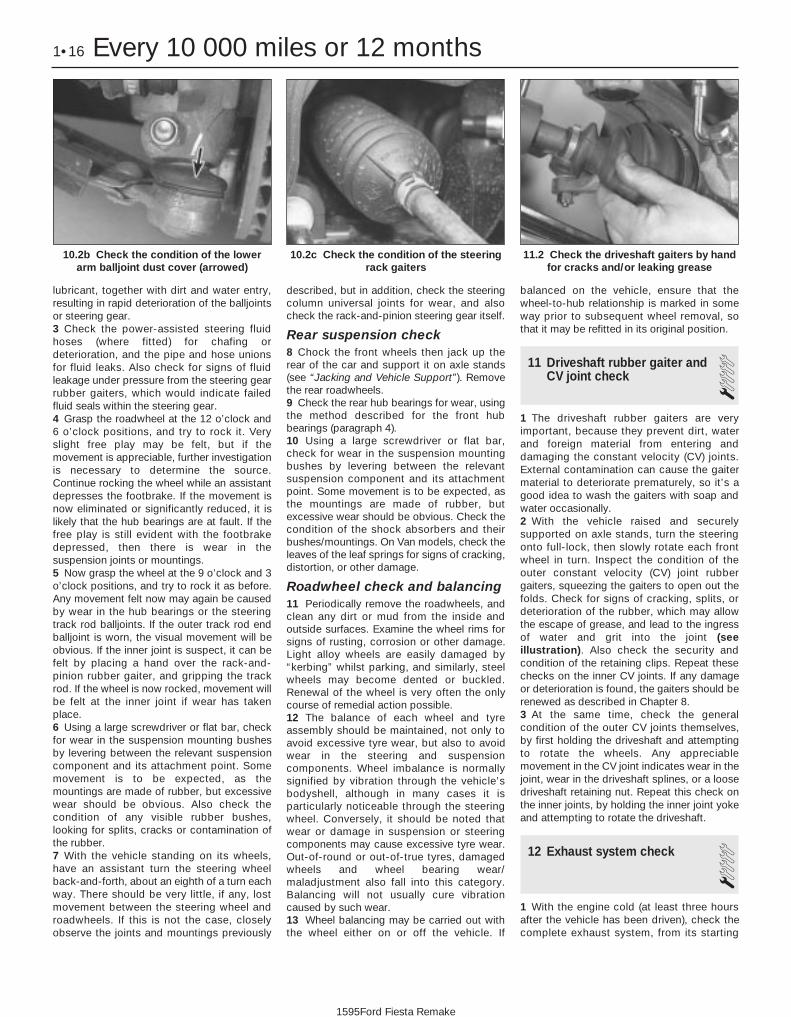
lubricant, together with dirt and water entry,resulting in rapid deterioration of the balljointsor steering gear.3 Check the power-assisted steering fluidhoses (where fitted) for chafing ordeterioration, and the pipe and hose unionsfor fluid leaks. Also check for signs of fluidleakage under pressure from the steering gearrubber gaiters, which would indicate failedfluid seals within the steering gear.4 Grasp the roadwheel at the 12 o’clock and6 o’clock positions, and try to rock it. Veryslight free play may be felt, but if themovement is appreciable, further investigationis necessary to determine the source.Continue rocking the wheel while an assistantdepresses the footbrake. If the movement isnow eliminated or significantly reduced, it islikely that the hub bearings are at fault. If thefree play is still evident with the footbrakedepressed, then there is wear in thesuspension joints or mountings.5 Now grasp the wheel at the 9 o’clock and 3o’clock positions, and try to rock it as before.Any movement felt now may again be causedby wear in the hub bearings or the steeringtrack rod balljoints. If the outer track rod endballjoint is worn, the visual movement will beobvious. If the inner joint is suspect, it can befelt by placing a hand over the rack-and-pinion rubber gaiter, and gripping the trackrod. If the wheel is now rocked, movement willbe felt at the inner joint if wear has takenplace.6 Using a large screwdriver or flat bar, checkfor wear in the suspension mounting bushesby levering between the relevant suspensioncomponent and its attachment point. Somemovement is to be expected, as themountings are made of rubber, but excessivewear should be obvious. Also check thecondition of any visible rubber bushes,looking for splits, cracks or contamination ofthe rubber.7 With the vehicle standing on its wheels,have an assistant turn the steering wheelback-and-forth, about an eighth of a turn eachway. There should be very little, if any, lostmovement between the steering wheel androadwheels. If this is not the case, closelyobserve the joints and mountings previously
described, but in addition, check the steeringcolumn universal joints for wear, and alsocheck the rack-and-pinion steering gear itself.
Rear suspension check8 Chock the front wheels then jack up therear of the car and support it on axle stands(see “Jacking and Vehicle Support”). Removethe rear roadwheels.9 Check the rear hub bearings for wear, usingthe method described for the front hubbearings (paragraph 4).10 Using a large screwdriver or flat bar,check for wear in the suspension mountingbushes by levering between the relevantsuspension component and its attachmentpoint. Some movement is to be expected, asthe mountings are made of rubber, butexcessive wear should be obvious. Check thecondition of the shock absorbers and theirbushes/mountings. On Van models, check theleaves of the leaf springs for signs of cracking,distortion, or other damage.
Roadwheel check and balancing11 Periodically remove the roadwheels, andclean any dirt or mud from the inside andoutside surfaces. Examine the wheel rims forsigns of rusting, corrosion or other damage.Light alloy wheels are easily damaged by“kerbing” whilst parking, and similarly, steelwheels may become dented or buckled.Renewal of the wheel is very often the onlycourse of remedial action possible.12 The balance of each wheel and tyreassembly should be maintained, not only toavoid excessive tyre wear, but also to avoidwear in the steering and suspensioncomponents. Wheel imbalance is normallysignified by vibration through the vehicle’sbodyshell, although in many cases it isparticularly noticeable through the steeringwheel. Conversely, it should be noted thatwear or damage in suspension or steeringcomponents may cause excessive tyre wear.Out-of-round or out-of-true tyres, damagedwheels and wheel bearing wear/maladjustment also fall into this category.Balancing will not usually cure vibrationcaused by such wear.13 Wheel balancing may be carried out withthe wheel either on or off the vehicle. If
balanced on the vehicle, ensure that thewheel-to-hub relationship is marked in someway prior to subsequent wheel removal, sothat it may be refitted in its original position.
11 Driveshaft rubber gaiter andCV joint check 1
1 The driveshaft rubber gaiters are veryimportant, because they prevent dirt, waterand foreign material from entering anddamaging the constant velocity (CV) joints.External contamination can cause the gaitermaterial to deteriorate prematurely, so it’s agood idea to wash the gaiters with soap andwater occasionally.2 With the vehicle raised and securelysupported on axle stands, turn the steeringonto full-lock, then slowly rotate each frontwheel in turn. Inspect the condition of theouter constant velocity (CV) joint rubbergaiters, squeezing the gaiters to open out thefolds. Check for signs of cracking, splits, ordeterioration of the rubber, which may allowthe escape of grease, and lead to the ingressof water and grit into the joint (seeillustration). Also check the security andcondition of the retaining clips. Repeat thesechecks on the inner CV joints. If any damageor deterioration is found, the gaiters should berenewed as described in Chapter 8.3 At the same time, check the generalcondition of the outer CV joints themselves,by first holding the driveshaft and attemptingto rotate the wheels. Any appreciablemovement in the CV joint indicates wear in thejoint, wear in the driveshaft splines, or a loosedriveshaft retaining nut. Repeat this check onthe inner joints, by holding the inner joint yokeand attempting to rotate the driveshaft.
12 Exhaust system check 11 With the engine cold (at least three hoursafter the vehicle has been driven), check thecomplete exhaust system, from its starting
1•16 Every 10 000 miles or 12 months
11.2 Check the driveshaft gaiters by handfor cracks and/or leaking grease
10.2c Check the condition of the steeringrack gaiters
10.2b Check the condition of the lowerarm balljoint dust cover (arrowed)
1595Ford Fiesta Remake

point at the engine to the end of the tailpipe.Ideally, this should be done on a hoist, whereunrestricted access is available; if a hoist isnot available, raise and support the vehicle onaxle stands.2 Check the pipes and connections forevidence of leaks, severe corrosion, ordamage. Make sure that all brackets andrubber mountings are in good condition, andtight; if any of the mountings are to berenewed, ensure that the replacements are ofthe correct type (see illustration). Leakage atany of the joints or in other parts of the systemwill usually show up as a black sooty stain inthe vicinity of the leak. Note: Exhaust sealantsshould not be used on any part of the exhaustsystem upstream of the catalytic converter -even if the sealant does not contain additivesharmful to the converter, pieces of it maybreak off and foul the element, causing localoverheating.3 At the same time, inspect the underside ofthe body for holes, corrosion, open seams,etc, which may allow exhaust gases to enterthe passenger compartment. Seal all bodyopenings with silicone or body putty.4 Rattles and other noises can often betraced to the exhaust system, especially therubber mountings. Try to move the system,silencer(s) and catalytic converter. If anycomponents can touch the body orsuspension parts, secure the exhaust systemwith new mountings.5 Check the running condition of the engineby inspecting inside the end of the tailpipe;the exhaust deposits here are an indication of the engine’s state of tune. The inside of thetailpipe should be dry, and should vary incolour from dark grey to light grey/brown; if itis black and sooty, or coated with whitedeposits, the engine is in need of a thoroughfuel system inspection.
13 Underbody and fuel/brakeline check 1
1 With the vehicle raised and supported onaxle stands or over an inspection pit,thoroughly inspect the underbody and wheelarches for signs of damage and corrosion. Inparticular, examine the bottom of the sidesills, and any concealed areas where mud cancollect. Where corrosion and rust is evident,press and tap firmly on the panel with ascrewdriver, and check for any seriouscorrosion which would necessitate repairs. Ifthe panel is not seriously corroded, cleanaway the rust, and apply a new coating ofunderseal. Refer to Chapter 11 for moredetails of body repairs.2 At the same time, inspect the PVC-coatedlower body panels for stone damage andgeneral condition.3 Inspect all of the fuel and brake lines on theunderbody for damage, rust, corrosion andleakage. Also make sure that they are
correctly supported in their clips. Whereapplicable, check the PVC coating on thelines for damage.
14 Brake check 2Note: For detailed photographs of the brakesystem, refer to Chapter 9.1 The work described in this Section shouldbe carried out at the specified intervals, orwhenever a defect is suspected in the brakingsystem. Any of the following symptoms couldindicate a potential brake system defect:a) The vehicle pulls to one side when the
brake pedal is depressed.b) The brakes make scraping or dragging
noises when applied.c) Brake pedal travel is excessive.d) The brake fluid requires repeated topping-
up.2 A thorough inspection should be made toconfirm the thickness of the linings, asfollows.
Front brakes3 Chock the rear wheels then jack up thefront of the car and support it on axle stands(see “Jacking and Vehicle Support”).4 For better access to the brake calipers,remove the wheels.5 Look through the inspection window in thecaliper, and check that the thickness of thefriction lining material on each of the pads isnot less than the recommended minimumthickness given in the Specifications. Note:Bear in mind that the lining material is normallybonded to a metal backing plate.6 If it is difficult to determine the exactthickness of the pad linings, or if you are at allconcerned about the condition of the pads,then remove them from the calipers for furtherinspection (refer to Chapter 9).7 Check the remaining brake caliper in thesame way.8 If any one of the brake pads has worn down
to, or below, the specified limit, all four padsmust be renewed as a set.9 Measure the thickness of the discs with amicrometer, if available, to make sure that theystill have service life remaining. If any disc isthinner than the specified minimum thickness,renew it (refer to Chapter 9). In any case,check the general condition of the discs. Lookfor excessive scoring and discolourationcaused by overheating. If these conditionsexist, remove the relevant disc and have itresurfaced or renewed (refer to Chapter 9).10 Before refitting the wheels and loweringthe car, check all brake lines and hoses (referto Chapter 9). In particular, check the flexiblehoses in the vicinity of the calipers, wherethey are subjected to most movement. Bendthem between the fingers (but do not actuallybend them double, or the casing may bedamaged) and check that this does not revealpreviously-hidden cracks, cuts or splits.
Rear brakes11 Chock the front wheels then jack up therear of the car and support it on axle stands(see “Jacking and Vehicle Support”).12 For better access, remove the rearwheels.13 To check the brake shoe lining thicknesswithout removing the brake drums, prise therubber plugs from the backplates, and use anelectric torch and mirror to inspect the liningsof the leading brake shoes. Check that thethickness of the lining material on the brakeshoes is not less than the recommendationgiven in the Specifications.14 If it is difficult to determine the exactthickness of the brake shoe linings, or if youare at all concerned about the condition of theshoes, then remove the rear drums for a morecomprehensive inspection (refer to Chap-ter 9).15 With the drum removed, check the shoereturn and hold-down springs for correctinstallation, and check the wheel cylinders forleakage of brake fluid. Check the frictionsurface of the brake drums for scoring anddiscoloration. If excessive, the drum shouldbe resurfaced or renewed.16 Before refitting the wheels, check allbrake lines and hoses (refer to Chapter 9). Oncompletion, apply the handbrake and checkthat the rear wheels are locked. Thehandbrake also requires periodic adjustment,and if its travel seems excessive, refer toSection 27.
15 Roadwheel nut tightnesscheck 1
1 Apply the handbrake.2 Remove the wheel covers, using the flatend of the wheelbrace supplied in the tool kit(on some models it will be necessary tounscrew the retaining bolts with a specialkey).
Every 10 000 miles or 12 months 1•17
12.2 Ensure that the exhaust systemrubber mountings replacements are of thecorrect type - their colour is a good guide.Those nearest to the catalytic converterare more heat-resistant than the others
1
1595Ford Fiesta Remake

3 Check that the roadwheel nuts are tightenedto the specified torque wrench setting.4 Refit the wheel covers.
16 Door, tailgate and bonnetcheck and lubrication 1
1 Check that the doors and tailgate/boot lidclose securely. Check that the bonnet safetycatch operates correctly. Check the operationof the door check straps.2 Lubricate the hinges, door check straps,the striker plates and the bonnet catchsparingly with a little oil or grease.
17 Seat belt check 11 Check the seat belts for satisfactoryoperation and condition. Inspect the webbingfor fraying and cuts. Check that they retractsmoothly and without binding into their reels.2 Check that the seat belt mounting bolts aretight, and if necessary tighten them to thespecified torque wrench settings as given inChapter 11.
18 Bodywork, paint and exteriortrim check 1
1 The best time to carry out this check is afterthe car has been washed so that any surfaceblemish or scratch will be clearly evident andnot hidden by a film of dirt.2 Starting at one front corner check thepaintwork all around the car, looking for minorscratches or more serious dents. Check allthe trim and make sure that it is securelyattached over its entire length.3 Check the security of all door locks, doormirrors, badges, bumpers, front grille andwheel trim. Anything found loose, or in need offurther attention should be done with referenceto the relevant Chapters of this manual.4 Rectify any problems noticed with thepaintwork or body panels as described inChapter 11.
19 Road test 1Check the operation andperformance of the brakingsystem1 Make sure that the vehicle does not pull toone side when braking, and that the wheelsdo not lock prematurely when braking hard.2 Check that there is no vibration through thesteering when braking.
3 Check that the handbrake operatescorrectly, without excessive movement of thelever, and that it holds the vehicle stationaryon a slope.4 Test the operation of the brake servo unitas follows. With the engine switched off,depress the footbrake four or five times toexhaust the vacuum, then hold the pedaldepressed. Start the engine, and there shouldbe a noticeable “give” in the brake pedal asvacuum builds up. Allow the engine to run forat least two minutes, and then switch it off. Ifthe brake pedal is depressed again, it shouldbe possible to detect a hiss from the servo asthe pedal is depressed. After about four or fiveapplications, no further hissing should beheard, and the pedal should feel considerablyfirmer.
Steering and suspension5 Check for any abnormalities in the steering,suspension, handling or road “feel”.6 Drive the vehicle, and check that there areno unusual vibrations or noises.7 Check that the steering feels positive, withno excessive sloppiness or roughness, andcheck for any suspension noises whencornering and driving over bumps.
Drivetrain8 Check the performance of the engine,transmission and driveshafts.9 Check that the engine starts correctly, bothwhen cold and when hot.10 Listen for any unusual noises from theengine and transmission.11 Make sure that the engine runs smoothlywhen idling, and that there is no hesitationwhen accelerating.12 On manual transmission models, checkthat all gears can be engaged smoothlywithout noise, and that the gear lever action isnot abnormally vague or “notchy”.13 On automatic transmission models, makesure that the drive seems smooth withoutjerks or engine speed “flare-ups”. Check thatall the gear positions can be selected with thevehicle at rest. If any problems are found, theyshould be referred to a Ford dealer.14 Listen for a metallic clicking sound fromthe front of the vehicle, as the vehicle is drivenslowly in a circle with the steering on full-lock.Carry out this check in both directions. If aclicking noise is heard, this indicates wear in adriveshaft joint, in which case renew the jointif necessary.
Clutch15 Check that the clutch pedal movessmoothly and easily through its full travel, andthat the clutch itself functions correctly, withno trace of slip or drag. If the movement isuneven or stiff in places, check that the cableis routed correctly, with no sharp turns.16 Inspect both ends of the clutch innercable, both at the transmission end and insidethe car, for signs of wear and fraying.
Instruments and electricalequipment17 Check the operation of all instrumentsand electrical equipment.18 Make sure that all instruments readcorrectly, and switch on all electrical equipmentin turn, to check that it functions properly.
20 Automatic transmission fluidlevel check 1
1 The level of the automatic transmission fluidshould be carefully maintained. Low fluid levelcan lead to slipping or loss of drive, whileoverfilling can cause foaming, loss of fluid andtransmission damage.2 The transmission fluid level should only bechecked when the transmission is hot (at itsnormal operating temperature). If the vehiclehas just been driven over 10 miles (15 miles ina cold climate), and the fluid temperature is 60to 70ºC, the transmission is hot.Caution: If the vehicle has just been drivenfor a long time at high speed or in citytraffic in hot weather, or if it has beenpulling a trailer, an accurate fluid levelreading cannot be obtained. In thesecircumstances, allow the fluid to cooldown for about 30 minutes.3 Park the vehicle on level ground, apply thehandbrake, and start the engine. While theengine is idling, depress the brake pedal andmove the selector lever through all the gearpositions three times, beginning and ending in“P”.4 Allow the engine to idle for one minute, then(with the engine still idling) remove thedipstick from its tube. Note the condition andcolour of the fluid on the dipstick.5 Wipe the fluid from the dipstick with a cleanrag, and re-insert it into the filler tube until thecap seats.6 Pull the dipstick out again, and note thefluid level. The level should be between the “MIN” and “MAX” marks. If the level is on the “MIN” mark, stop the engine, and addthe specified automatic transmission fluidthrough the dipstick tube, using a clean funnelif necessary. It is important not to introducedirt into the transmission when topping-up.7 Add the fluid a little at a time, and keepchecking the level as previously describeduntil it is correct. The difference between the“MIN” and “MAX” marks on the dipstick isapproximately 0.4 litres.8 The need for regular topping-up of thetransmission fluid indicates a leak, whichshould be found and rectified without delay.9 The condition of the fluid should also bechecked along with the level. If the fluid on thedipstick is black or a dark reddish-browncolour, or if it has a burned smell, the fluidshould be changed. If you are in doubt aboutthe condition of the fluid, purchase some newfluid, and compare the two for colour and smell.
1•18 Every 10 000 miles or 12 months
1595Ford Fiesta Remake

21 Spark plug renewal and HTcomponent check 1
Note: Spark plug renewal at this serviceinterval is only necessary on the HCS, CVHand PTE engines. On Zetec engines, therecommended interval for spark plug renewalis every 30 000 miles or three years.
Spark plug check and renewal1 It is vital for the correct running, fullperformance and proper economy of the enginethat the spark plugs perform with maximumefficiency. The most important factor in ensuringthis is that the plugs fitted are appropriate for theengine. The suitable type is given in theSpecifications Section at the beginning of thisChapter, on the Vehicle Emissions ControlInformation (VECI) label located on theunderside of the bonnet (only on models sold insome areas) or in the vehicle’s Owner’sHandbook. If the correct type is used and theengine is in good condition, the spark plugsshould not need attention between scheduledrenewal intervals. Spark plug cleaning is rarelynecessary, and should not be attempted unlessspecialised equipment is available, as damagecan easily be caused to the firing ends.2 Spark plug removal and refitting requires aspark plug socket, with an extension which canbe turned by a ratchet handle or similar. Thissocket is lined with a rubber sleeve, to protectthe porcelain insulator of the spark plug, and tohold the plug while you insert it into the sparkplug hole. You will also need a set of feelergauges, to check the spark plug electrode gap,and a torque wrench to tighten the new plugsto the specified torque (see illustration).3 To remove the spark plugs, first open thebonnet; the plugs are easily reached at thetop of the engine. Note how the spark plug(HT) leads are routed and secured by clips,and on some engines, how they’re positionedalong the channel in the cylinder head cover.To prevent the possibility of mixing up sparkplug (HT) leads, it is a good idea to try to workon one spark plug at a time.4 If the marks on the original-equipment sparkplug (HT) leads cannot be seen, mark the leads1 to 4, to correspond to the cylinder the leadserves (No 1 cylinder is at the timing belt/chainend of the engine). Pull the leads from the plugsby gripping the rubber boot, not the lead,otherwise the lead connection may be fractured.5 It is advisable to soak up any liquid in thespark plug recesses with a rag, and to removeany dirt from them using a clean brush,vacuum cleaner or compressed air beforeremoving the plugs, to prevent any dirt orwater from dropping into the cylinders.
Warning: Wear eye protectionwhen using compressed air!
6 Unscrew the spark plugs, ensuring that thesocket is kept in alignment with each plug - ifthe socket is forcibly moved to either side, theporcelain top of the plug may be broken off. Ifany undue difficulty is encountered whenunscrewing any of the spark plugs, carefullycheck the cylinder head threads and taperedsealing surfaces for signs of wear, excessivecorrosion or damage; if any of theseconditions is found, seek the advice of a Forddealer as to the best method of repair.7 As each plug is removed, examine it asfollows - this will give a good indication of thecondition of the engine. If the insulator nose iscovered with light tan to greyish-browndeposits, then the mixture is correct, and it islikely that the engine is in good condition.8 If the tip and insulator nose are coveredwith hard black-looking deposits, then this isindicative that the mixture is too rich. Shouldthe plug be black and oily, then it is likely thatthe engine is fairly worn, as well as the mixturebeing too rich.9 If the insulator nose of the spark plug is
clean and white, with no deposits, this isindicative of a weak mixture.10 If you are renewing the spark plugs,purchase the new plugs, then check each ofthem first for faults such as cracked insulatorsor damaged threads. Note also that,whenever the spark plugs are renewed as aroutine service operation, the spark plug (HT)leads should be checked as described below.11 The spark plug electrode gap is ofconsiderable importance as, if it is too large ortoo small, the size of the spark and itsefficiency will be seriously impaired. The gapshould be set to the value given in theSpecifications Section of this Chapter. Newplugs will not necessarily be set to the correctgap, so they should always be checkedbefore fitting.12 The spark plug gap is correct when thecorrect-size feeler gauge or wire gauge is afirm sliding fit between the electrodes (seeillustrations).13 To adjust the electrode gap, bend open, orclose up, the outer plug electrode until thecorrect gap is achieved (see illustration). Thecentre electrode should never be bent, as thismay crack the insulation and cause plug failure,
Every 20 000 miles (32 000 km) or two years, whichevercomes first
Every 20 000 miles or two years 1•19
21.12b Spark plug manufacturersrecommend using a wire-type gauge when
checking the gap - if the wire or feeler gaugedoes not slide between the electrodes with a
slight drag, adjustment is required
21.12a Measuring a spark plug gap with afeeler gauge
21.2 Tools required for changing sparkplugs
21.13 To change the gap, bend the outerelectrode only, and be very careful not to
crack or chip the porcelain insulatorsurrounding the centre electrode
1
1595Ford Fiesta Remake

if nothing worse. If the outer electrode is notexactly over the centre electrode, bend it gentlyto align them. Special spark plug gap adjustingtools are available from motor accessory shops,or from certain spark plug manufacturers.14 Before fitting the spark plugs, check thatthe threaded connector sleeves at the top ofthe plugs are tight, and that the plug exteriorsurfaces and threads are clean. Brownstaining on the porcelain, immediately abovethe metal body, is quite normal, and does notnecessarily indicate a “leak” between thebody and insulator.15 Apply a smear of copper-based grease oranti-seize compound to the threads of eachplug, and screw them in by hand wherepossible. Take extra care to enter the plugthreads correctly, as the cylinder head is ofaluminium alloy.
16 When each spark plug is started correctlyon its threads, screw it down until it just seatslightly, then tighten it to the specified torquewrench setting. If a torque wrench is notavailable - and this is one case where the use ofa torque wrench is strongly recommended -tighten each spark plug through no more than1/4 of a turn (CVH and PTE engines) or 1/16 of aturn (HCS and Zetec engines) after it seats. HCSand Zetec engines are fitted with taper-seatspark plugs, identifiable by not having a sealingwasher, and these in particular should NEVERbe overtightened - their tapered seats meanthey are almost impossible to remove if abused.17 Reconnect the spark plug (HT) leads intheir correct order, using a twisting motion onthe boot until it is firmly seated on the end ofthe spark plug and on the cylinder head cover.
Spark plug (HT) lead, distributorcap and rotor arm check18 The spark plug (HT) leads should bechecked whenever the plugs themselves are
renewed. Start by making a visual check ofthe leads while the engine is running. In adarkened garage (make sure there isventilation) start the engine and observe eachlead. Be careful not to come into contact withany moving engine parts. If there is a break inthe lead, you will see arcing or a small sparkat the damaged area.19 The spark plug (HT) leads should beinspected one at a time, to prevent mixing upthe firing order, which is essential for properengine operation. Each original lead should be numbered to identify its cylinder. If thenumber is illegible, a piece of tape can bemarked with the correct number, andwrapped around the lead (the leads should benumbered 1 to 4, with No 1 lead nearest thetiming belt end of the engine). The lead canthen be disconnected.20 Check inside the boot for corrosion, whichwill look like a white crusty powder. Clean thisoff as much as possible; if it is excessive, or ifcleaning leaves the metal connector too badlyeroded to be fit for further use, the lead mustbe renewed. Push the lead and boot backonto the end of the spark plug. The bootshould fit tightly onto the end of the plug - if itdoesn’t, remove the lead and use plierscarefully to crimp the metal connector insidethe boot until the fit is snug.21 Using a clean rag, wipe the entire lengthof the lead to remove built-up dirt and grease.Once the lead is clean, check for burns,cracks and other damage. Do not bend thelead sharply, because the conductor mightbreak.22 Disconnect the lead from the ignition coilby pressing together the plastic retainingcatches (where fitted) and pulling the endfitting off the coil terminal. Check for corrosionand for a tight fit. If a meter with the correctmeasuring range is available, measure theresistance of the disconnected lead from itscoil connector to its spark plug connector. Ifthe resistance recorded for any of the leadsexceeds the value specified, all the leadsshould be renewed as a set. Refit the lead tothe coil, noting that each coil terminal ismarked with its respective cylinder number,so that there is no risk of mixing up the leadsand upsetting the firing order.23 Inspect the remaining spark plug (HT)leads, ensuring that each is securely fastenedat the distributor cap or ignition coil and sparkplug when the check is complete. If any signof arcing, severe connector corrosion, burns,cracks or other damage is noticed, obtain newspark plug (HT) leads, renewing them as a set.If new spark plug leads are to be fitted,remove and refit them one at a time, to avoidmix-ups in the firing order.
24 On models with distributor ignitionsystems, refer to Chapter 5B and remove thedistributor cap then thoroughly clean it insideand out with a dry lint-free rag.25 Examine the HT lead segments inside thecap. If they appear badly burned or pittedrenew the cap. Also check the carbon brushin the centre of the cap, ensuring that it is freeto move and stands proud of its holder. Makesure that there are no sign of cracks or black“tracking” lines running down the inside of thecap, which will also mean renewal if evident. 26 Inspect the rotor arm checking it forsecurity and also for signs of deterioration asdescribed above.27 Refit the cap as described in Chapter 5Bon completion.
22 Idle speed control valvecleaning and maintenance 1
Note: The idle speed control valve may bemounted on the air cleaner, on the enginecompartment bulkhead, or on the side of the inletmanifold according to valve make and year ofmanufacture. Valves manufactured by Weber aremounted on the air cleaner and only these valvesrequire the periodic maintenance describedbelow. Bulkhead and inlet manifold mountedvalves are manufactured by Hitachi and aremaintenance free. Refer to the warning note inSection 1 of Chapter 4C before proceeding.1 Remove the valve as described in Chap-ter 4C, Section 14.2 Immerse the valve head in a suitablecontainer filled with clean petrol, and allow itto soak for approximately three minutes.3 Clean the valve bore, slots and piston withpetrol, using a suitable lint-free cloth, thengently move the piston up and down in itsbore using a small screwdriver (seeillustration). Ensure that no cloth particlesenter the bore, and do not use the slots tomove the piston.4 Rinse the valve again with clean petrol, thendry it using an air line (or other source ofcompressed air).
Warning: Wear eye protectionwhen using compressed air!
5 Clean the mating faces of the valve and theair filter housing then refit as described inChapter 4C, Section 14.
1•20 Every 20 000 miles or two years
22.3 Gently move the idle speed controlvalve piston up and down in its bore usinga small screwdriver (1.6 litre EFi engine)
1595Ford Fiesta Remake
It’s often difficult to insert spark plugsinto their holes without cross-threadingthem. To avoid this possibility, fit ashort piece of rubber hose over the endof the spark plug. The flexible hoseacts as a universal joint, to help alignthe plug with the plug hole. Should theplug begin to cross-thread, the hosewill slip on the spark plug, preventingthread damage.
If new spark plug leads are tobe fitted, remove the leadsone at a time and fit eachnew lead in exactly the sameposition as the old one.

23 Coolant renewal 1Note: If the antifreeze used is Ford’s own, thecoolant need not be renewed for the life of thevehicle. If the vehicle’s history is unknown, ifantifreeze of lesser quality is known to be inthe system, or simply if you prefer to followconventional servicing intervals, the coolantshould be changed periodically (typically,every 3 years) as described here. Refer also to“Antifreeze - notes on renewal” in thisSection.
Warning: Do not allowantifreeze to come in contactwith your skin or paintedsurfaces of the vehicle. Flush
contaminated areas immediately withplenty of water. Don’t store new coolant,or leave old coolant lying around, whereit’s accessible to children or pets - they’reattracted by its sweet smell. Ingestion ofeven a small amount of coolant can befatal! Wipe up garage-floor and drip-panspills immediately. Keep antifreezecontainers covered, and repair coolingsystem leaks as soon as they’re noticed.Warning: Never remove the expansiontank filler cap when the engine is running,or has just been switched off, as thecooling system will be hot, and theconsequent escaping steam and scaldingcoolant could cause serious injury.
Coolant drainingWarning: Wait until the engine iscold before starting thisprocedure.
1 To drain the system, first remove theexpansion tank filler cap (see “WeeklyChecks”).2 If additional working clearance is required,raise the front of the vehicle and support it
securely on axle stands (see “Jacking andVehicle Support”).3 Place a large drain tray beneath theradiator, and unscrew the radiator drain plug -you can use a small coin to do this, as theplug’s slotted for this purpose (seeillustration). Direct as much of the escapingcoolant as possible into the tray.
System flushing4 With time, the cooling system may graduallylose its efficiency, as the radiator corebecomes choked with rust, scale depositsfrom the water, and other sediment (refer alsoto “Antifreeze - notes on renewal” later in thisSection). To minimise this, as well as usingonly good-quality antifreeze and clean softwater, the system should be flushed as followswhenever any part of it is disturbed, and/orwhen the coolant is renewed.5 With the coolant drained, refit the drainplug, and refill the system with fresh water.Refit the expansion tank filler cap, start theengine and warm it up to normal operatingtemperature, then stop it and (after allowing itto cool down completely) drain the systemagain. Repeat as necessary until only cleanwater can be seen to emerge, then refill finallywith the specified coolant mixture asdescribed below.6 If only clean, soft water and good-qualityantifreeze (even if not to Ford’s specification)has been used, and the coolant has beenrenewed at the suggested intervals, the aboveprocedure will be sufficient to keep thesystem clean for a considerable length oftime. If, however, the system has beenneglected, a more thorough operation will berequired, as follows.7 First drain the coolant, then disconnect theradiator top and bottom hoses. Insert agarden hose into the top hose, and allowwater to circulate through the radiator until itruns clean from the bottom outlet.8 To flush the engine, insert the garden hoseinto the thermostat water outlet, and allowwater to circulate until it runs clear from thebottom hose. If, after a reasonable period, thewater still does not run clear, the radiatorshould be flushed with a good proprietarycleaning agent.9 In severe cases of contamination, reverse-flushing of the radiator may be necessary. Todo this, remove the radiator (Chapter 3), invertit, and insert the garden hose into the bottomoutlet. Continue flushing until clear water runsfrom the top hose outlet. A similar procedurecan be used to flush the heater matrix.10 The use of chemical cleaners should benecessary only as a last resort. Normally,regular renewal of the coolant will preventexcessive contamination of the system.
Coolant filling11 With the cooling system drained andflushed, ensure that all disturbed hose unionsare correctly secured, and that the radiatordrain plug is securely tightened. If it wasraised, lower the vehicle to the ground.12 Prepare a sufficient quantity of thespecified coolant mixture (see below); allowfor a surplus, so as to have a reserve supplyfor topping-up.13 Slowly fill the system through theexpansion tank; since the tank is the highestpoint in the system, all the air in the systemshould be displaced into the tank by the risingliquid. Slow pouring reduces the possibility ofair being trapped and forming airlocks.14 Continue filling until the coolant levelreaches the expansion tank “MAX” level line,then cover the filler opening to preventcoolant splashing out.15 Start the engine and run it at idle speed,until it has warmed-up to normal operatingtemperature and the radiator cooling fan hascut in; watch the temperature gauge to checkfor signs of overheating. If the level in theexpansion tank drops significantly, top-up tothe “MAX” level line, to minimise the amountof air circulating in the system.16 Stop the engine, allow it to cool downcompletely (overnight, if possible), thenuncover the expansion tank filler opening andtop-up the tank to the “MAX” level line. Refitthe filler cap, tightening it securely, and washoff any spilt coolant from the enginecompartment and bodywork.17 After refilling, always check carefully allcomponents of the system (but especially anyunions disturbed during draining and flushing)for signs of coolant leaks. Fresh antifreeze hasa searching action, which will rapidly exposeany weak points in the system.18 If, after draining and refilling the system,symptoms of overheating are found which didnot occur previously, then the fault is almostcertainly due to trapped air at some point inthe system, causing an airlock and restrictingthe flow of coolant; usually, the air is trappedbecause the system was refilled too quickly.In some cases, airlocks can be released bytapping or squeezing the various hoses. If theproblem persists, stop the engine and allow itto cool down completely, before unscrewingthe expansion tank filler cap or disconnectinghoses to bleed out the trapped air.
Antifreeze mixture19 If the antifreeze used is not to Ford’sspecification, it should always be renewed atthe suggested intervals (typically, every 2 or 3 years). This is necessary not only to maintainthe antifreeze properties, but also to prevent
Every 30 000 miles (48 000 km) or three years, whichevercomes first
Every 30 000 miles or three years 1•21
23.3 Drain plug location at the base of theradiator - use a coin to unscrew the plug
1
1595Ford Fiesta Remake

the corrosion which would otherwise occur as the corrosion inhibitors become progress-ively less effective. Always use an ethyleneglycol-based antifreeze which is suitable foruse in mixed-metal cooling systems.20 If the antifreeze used is to Ford’sspecification, the levels of protection it affordsare indicated in the Specifications Section ofthis Chapter. To give the recommendedstandard mixture ratio for this antifreeze, 40%(by volume) of antifreeze must be mixed with60% of clean, soft water; if you are using anyother type of antifreeze, follow itsmanufacturer’s instructions to achieve thecorrect ratio. It is best to make up slightlymore than the system’s specified capacity, sothat a supply is available for subsequenttopping-up.21 Before adding antifreeze, the coolingsystem should be completely drained,preferably flushed, and all hoses checked forcondition and security. As noted earlier, freshantifreeze will rapidly find any weaknesses inthe system.22 After filling with antifreeze, a label shouldbe attached to the expansion tank, stating thetype and concentration of antifreeze used,and the date installed. Any subsequenttopping-up should be made with the sametype and concentration of antifreeze. Iftopping-up using antifreeze to Ford’sspecification, note that a 50/50 mixture ispermissible, purely for convenience.23 Do not use engine antifreeze in thewindscreen/tailgate washer system, as it willdamage the vehicle’s paintwork. Ascreenwash additive should be added to thewasher system in its maker’s recommendedquantities.
Antifreeze - notes on renewal24 Ford state that, where antifreeze to Fordspecification ESD-M97B-49-A is used, it willlast the lifetime of the vehicle. This is subjectto it being used in the recommendedconcentration, unmixed with any other type ofantifreeze or additive, and topped-up whennecessary using only that antifreeze mixed
50/50 with clean water. If any other type ofantifreeze is added, the lifetime guarantee nolonger applies; to restore the lifetimeprotection, the system must be drained andthoroughly reverse-flushed before freshcoolant mixture is poured in.25 If the vehicle’s history (and therefore thequality of the antifreeze in it) is unknown,owners who wish to follow Ford’srecommendations are advised to drain andthoroughly reverse-flush the system beforerefilling with fresh coolant mixture. If theappropriate quality of antifreeze is used, thecoolant can then be left for the life of thevehicle.26 If any antifreeze other than Ford’s is to beused, the coolant must be renewed at regularintervals to provide an equivalent degree ofprotection; the conventional recommendationis to renew the coolant every two or threeyears.27 The above assumes the use of a mixture(in exactly the specified concentration) ofclean, soft water and of antifreeze to Ford’sspecification or equivalent. It is also assumedthat the cooling system is maintained in ascrupulously-clean condition, by ensuring thatonly clean coolant is added on topping-up,and by thorough reverse-flushing wheneverthe coolant is drained.
General cooling system checks28 The engine should be cold for the coolingsystem checks, so perform the followingprocedure before driving the vehicle, or after it has been shut off for at least threehours.29 Remove the expansion tank filler cap, andclean it thoroughly inside and out with a rag.Also clean the filler neck on the expansiontank. The presence of rust or corrosion in thefiller neck indicates that the coolant should bechanged. The coolant inside the expansiontank should be relatively clean andtransparent. If it is rust-coloured, drain andflush the system, and refill with a fresh coolantmixture.30 Carefully check the radiator hoses and
heater hoses along their entire length; renewany hose which is cracked, swollen ordeteriorated (see Section 5).31 Inspect all other cooling systemcomponents (joint faces, etc.) for leaks. A leakin the cooling system will usually show up aswhite- or rust-coloured deposits on the areaadjoining the leak. Where any problems of thisnature are found on system components,renew the component or gasket withreference to Chapter 3.32 Clean the front of the radiator with a softbrush to remove all insects, leaves, etc,embedded in the radiator fins. Be careful notto damage the radiator fins, or cut your fingerson them.
24 Air cleaner element renewal 11 The air cleaner filter element is located inthe air cleaner assembly mounted either ontop of the carburettor or CFi unit, or on theleft-hand or right-hand side of the enginecompartment at the front. Remove the aircleaner lid as follows according to type.
Carburettor and CFi fuelinjection models2 Undo the two or three retaining screws onthe top of the air cleaner lid (see illustration).3 Release the clips, and lift off the air cleanercover (see illustration).
EFi fuel injection models4 If the idle speed control valve is mounted on the air cleaner, disconnect themulti-plug and the air bypass hose from thevalve.5 Disconnect the flexible hose between theair cleaner lid and the air inlet duct orturbocharger air intake.6 Release the retaining clips and lift off the aircleaner lid (see illustration).
1•22 Every 30 000 miles or three years
24.6 On EFi fuel injection engines, releasethe retaining clips and lift off the air
cleaner lid
24.3 . . . then spring back the clips and liftof the lid
24.2 On carburettor and CFi fuel injectionengines, undo the air cleaner lid retaining
screws . . .
1595Ford Fiesta Remake

SEFi fuel injection models7 Disconnect the mass air flow sensor wiringmulti-plug (see illustration).8 Slacken the hose clip and disconnect theflexible rubber intake hose from the blackplastic air intake duct (see illustration).9 Undo the retaining screws or release theclips and lift off the air cleaner lid completewith mass air flow sensor (see illustration).
All models10 Lift out the element, and wipe out thehousing (see illustrations). Check that noforeign matter is visible, either in the air inletor in the air mass meter, as applicable.11 If carrying out a routine service, theelement must be renewed regardless of itsapparent condition. Note that on models soequipped, the small foam PCV filter in the rearright-hand corner of the air cleaner housingmust be cleaned whenever the air filterelement is renewed (see Section 25).12 If you are checking the element for anyother reason, inspect its lower surface; if it isoily or very dirty, renew the element. If it isonly moderately dusty, it can be re-used afterblowing it clean from the upper to the lowersurface with compressed air.
Warning: Wear eye protectionwhen using compressed air!Because it is a pleated-papertype filter, it cannot be washedor re-oiled. If it cannot be
cleaned satisfactorily with compressed air,discard and renew it. Caution: Never drive the vehicle with theair cleaner filter element removed.Excessive engine wear could result, andbackfiring could even cause a fire underthe bonnet.13 Refitting is the reverse of the removalprocedure. Ensure that the element and coverare securely seated, so that unfiltered aircannot enter the engine.
Air cleaner temperature controlsystem check (carburettormodels)14 In order for the engine to operateefficiently, the temperature of the air enteringthe inlet system must be controlled withincertain limits.15 The air cleaner has two sources of air, onedirect from the outside of the enginecompartment, and the other from a shroud onthe exhaust manifold. On HCS engines, awax-controlled thermostatic valve controls aflap inside the air cleaner inlet. When theambient air temperature is below apredetermined level, the flap admits airheated from the exhaust manifold shroud; asthe ambient temperature rises, the flap opensto admit more cool air from the enginecompartment until eventually it is fully open. Asimilar system is used on CVH engines,except that a vacuum actuator modifies any
opening or closing action of the temperaturesensor on the flap valve, according to the levelof the inlet manifold vacuum under runningconditions.
HCS engines16 This check must be made when theengine is cold. Detach and remove the aircleaner inlet trunking. Examine the position ofthe check valve within the duct. When theunderbonnet air temperature is below 28ºC,the valve must be open to allow hot air toenter the filter (see illustration).17 Refit the inlet trunking. Start the engineand run it until it reaches its normal operatingtemperature, then stop the engine, removethe inlet trunking and check that the valve hasclosed off the air passage from the exhaustand opened the main (cool) air inlet.18 If the flap does not operate correctly,check that it is not seized. Apart from thisthere is no adjustment possible, and the unitshould be renewed if faulty. Refit the air inlettrunking on completion.
CVH engines19 This check must be made when theengine is cold. Disconnect the main air inletduct, and visibly check that the flap to thehot-air inlet is closed (i.e. open to the passageof cold air).20 Start the engine, and check that with the
Every 30 000 miles or three years 1•23
24.9 . . . then undo the retaining screws orrelease the clips and lift off the air cleaner
lid complete with mass air flow sensor
24.8 . . . slacken the hose clip anddisconnect the intake hose from the air
intake duct . . .
24.7 On SEFi fuel injection engines,disconnect the mass air flow sensor wiring
multi-plug . . .
24.16 Air cleaner inlet and flap valve onthe HCS engine
A Main air cleaner inlet (cool air)B Warm air duct (flap open)
24.10b . . . and on EFi and SEFi fuelinjection engine models
24.10a Removing the air filter element oncarburettor engine models . . .
1
1595Ford Fiesta Remake
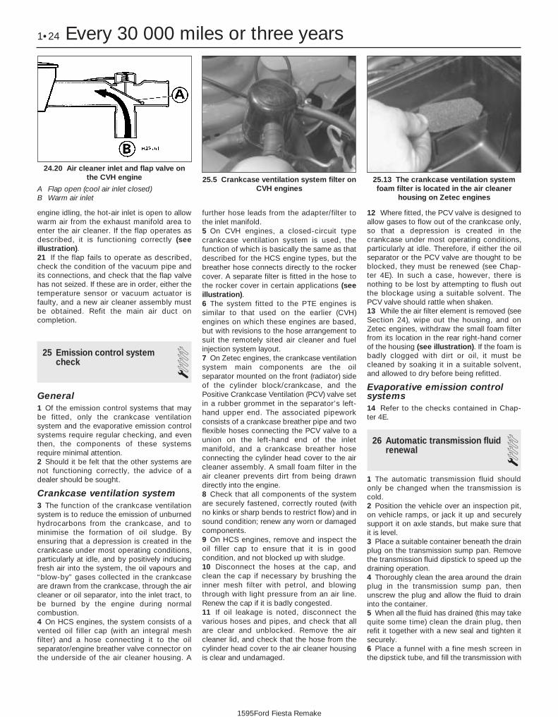
engine idling, the hot-air inlet is open to allowwarm air from the exhaust manifold area toenter the air cleaner. If the flap operates asdescribed, it is functioning correctly (seeillustration).21 If the flap fails to operate as described,check the condition of the vacuum pipe andits connections, and check that the flap valvehas not seized. If these are in order, either thetemperature sensor or vacuum actuator isfaulty, and a new air cleaner assembly mustbe obtained. Refit the main air duct oncompletion.
25 Emission control systemcheck 1
General1 Of the emission control systems that maybe fitted, only the crankcase ventilationsystem and the evaporative emission controlsystems require regular checking, and eventhen, the components of these systemsrequire minimal attention.2 Should it be felt that the other systems arenot functioning correctly, the advice of adealer should be sought.
Crankcase ventilation system3 The function of the crankcase ventilationsystem is to reduce the emission of unburnedhydrocarbons from the crankcase, and tominimise the formation of oil sludge. Byensuring that a depression is created in thecrankcase under most operating conditions,particularly at idle, and by positively inducingfresh air into the system, the oil vapours and“blow-by” gases collected in the crankcaseare drawn from the crankcase, through the aircleaner or oil separator, into the inlet tract, tobe burned by the engine during normalcombustion.4 On HCS engines, the system consists of avented oil filler cap (with an integral meshfilter) and a hose connecting it to the oilseparator/engine breather valve connector onthe underside of the air cleaner housing. A
further hose leads from the adapter/filter tothe inlet manifold.5 On CVH engines, a closed-circuit typecrankcase ventilation system is used, thefunction of which is basically the same as thatdescribed for the HCS engine types, but thebreather hose connects directly to the rockercover. A separate filter is fitted in the hose tothe rocker cover in certain applications (seeillustration).6 The system fitted to the PTE engines issimilar to that used on the earlier (CVH)engines on which these engines are based,but with revisions to the hose arrangement tosuit the remotely sited air cleaner and fuelinjection system layout.7 On Zetec engines, the crankcase ventilationsystem main components are the oilseparator mounted on the front (radiator) sideof the cylinder block/crankcase, and thePositive Crankcase Ventilation (PCV) valve setin a rubber grommet in the separator’s left-hand upper end. The associated pipeworkconsists of a crankcase breather pipe and twoflexible hoses connecting the PCV valve to aunion on the left-hand end of the inletmanifold, and a crankcase breather hoseconnecting the cylinder head cover to the aircleaner assembly. A small foam filter in the air cleaner prevents dirt from being drawndirectly into the engine.8 Check that all components of the systemare securely fastened, correctly routed (withno kinks or sharp bends to restrict flow) and insound condition; renew any worn or damagedcomponents.9 On HCS engines, remove and inspect theoil filler cap to ensure that it is in goodcondition, and not blocked up with sludge.10 Disconnect the hoses at the cap, andclean the cap if necessary by brushing theinner mesh filter with petrol, and blowingthrough with light pressure from an air line.Renew the cap if it is badly congested.11 If oil leakage is noted, disconnect thevarious hoses and pipes, and check that allare clear and unblocked. Remove the aircleaner lid, and check that the hose from thecylinder head cover to the air cleaner housingis clear and undamaged.
12 Where fitted, the PCV valve is designed toallow gases to flow out of the crankcase only,so that a depression is created in thecrankcase under most operating conditions,particularly at idle. Therefore, if either the oilseparator or the PCV valve are thought to beblocked, they must be renewed (see Chap-ter 4E). In such a case, however, there isnothing to be lost by attempting to flush outthe blockage using a suitable solvent. ThePCV valve should rattle when shaken.13 While the air filter element is removed (seeSection 24), wipe out the housing, and onZetec engines, withdraw the small foam filterfrom its location in the rear right-hand cornerof the housing (see illustration). If the foam isbadly clogged with dirt or oil, it must becleaned by soaking it in a suitable solvent,and allowed to dry before being refitted.
Evaporative emission controlsystems14 Refer to the checks contained in Chap-ter 4E.
26 Automatic transmission fluidrenewal 1
1 The automatic transmission fluid shouldonly be changed when the transmission iscold.2 Position the vehicle over an inspection pit,on vehicle ramps, or jack it up and securelysupport it on axle stands, but make sure thatit is level.3 Place a suitable container beneath the drainplug on the transmission sump pan. Removethe transmission fluid dipstick to speed up thedraining operation.4 Thoroughly clean the area around the drainplug in the transmission sump pan, thenunscrew the plug and allow the fluid to draininto the container.5 When all the fluid has drained (this may takequite some time) clean the drain plug, thenrefit it together with a new seal and tighten itsecurely.6 Place a funnel with a fine mesh screen inthe dipstick tube, and fill the transmission with
1•24 Every 30 000 miles or three years
25.13 The crankcase ventilation systemfoam filter is located in the air cleaner
housing on Zetec engines
25.5 Crankcase ventilation system filter onCVH engines
24.20 Air cleaner inlet and flap valve onthe CVH engine
A Flap open (cool air inlet closed)B Warm air inlet
1595Ford Fiesta Remake

the specified type of fluid. It is essential thatno dirt is introduced into the transmissionduring this operation.7 Depending on the extent to which the fluidwas allowed to drain, it is possible that theamount of fluid required when filling thetransmission may be more than the specifiedamount (see “Lubricants, fluids and tyrepressures”). However, due to fluid remaining inthe system, it is more likely that less than thespecified amount will be required. Add abouthalf the specified amount, then run the engineup to its normal operating temperature andcheck the level on the dipstick. When the levelapproaches the maximum mark, proceed asdetailed in Section 20 to check the level andcomplete the final topping-up as described.
27 Handbrake adjustment 31 Chock the front wheels then jack up therear of the car and support it on axle stands(see “Jacking and Vehicle Support”). Fullyrelease the handbrake.2 Check that the handbrake cables arecorrectly routed and secured by the retainingclips at the appropriate points under the vehicle.3 The handbrake is checked for adjustmentby measuring the amount of movementpossible in the handbrake adjuster plungers.These are located on the inside face of eachrear brake backplate (see illustration). The
total movement of the two plungers combinedshould be between 0.5 and 2.0 mm. If themovement measured is outside of thistolerance, the handbrake is in need ofadjustment. Adjustment is made altering theposition of the in-line cable adjuster sleeve.4 When adjustment to the handbrake isnecessary, a new adjustment sleeve lockingpin will be required, and this must thereforebe obtained before making the adjustment.5 To adjust the handbrake, first ensure that itis fully released, then firmly apply thefootbrake a few times to ensure that the rearbrake adjustment is taken up by the automaticadjusters. Extract the locking pin from the adjuster sleeve (see illustration), thenturn the sleeve to set the combined move-ment of the plungers within the tolerance
range specified (0.5 to 2.0 mm). Turn thelocking nut by hand as tight as is possible(two clicks) against the adjustment sleeve.Now grip the locknut with a suitable wrench,and turn it a further two clicks (maximum).6 Secure the adjustment by inserting the newlock pin.7 Check that the operation of the handbrakeis satisfactory, then lower the vehicle to theground, apply the handbrake and remove thechocks from the front wheels.
28 Front wheel alignment check 4Refer to Chapter 10, Section 29.
Every 30 000 miles or three years 1•25
27.5 Handbrake cable adjuster locking pin (A), locknut (B) and adjuster sleeve (C)
27.3 Handbrake adjustment plungerlocated on the inside face of each rear
brake backplate
1
1595Ford Fiesta Remake
Every 40 000 miles
29 Timing belt renewal 4Refer to Chapter 2, Part B or C as
applicable.
Every 60 000 miles
30 Fuel filter renewal 1Warning: Petrol is extremelyflammable, so extra precautionsmust be taken when working onany part of the fuel system. Do
not smoke, or allow open flames or barelight bulbs, near the work area. Also, donot work in a garage if a natural gas-typeappliance with a pilot light is present.While performing any work on the fuel
system, wear safety glasses, and have asuitable (Class B) fire extinguisher onhand. If you spill any fuel on your skin,rinse it off immediately with soap andwater.1 On fuel injection engines, an in-line fuelfilter is provided in the fuel pump outlet line.The filter is located in the engine compartmenteither below and behind the battery, or on theleft-hand side of the engine compartmentbulkhead. The renewal procedure is the samefor both locations. The filter performs a vitalrole in keeping dirt and other foreign matterout of the fuel system, and so must be
renewed at regular intervals, or whenever youhave reason to suspect that it may beclogged. It is always unpleasant workingunder a vehicle - pressure-washing or hosingclean the underbody in the filter’s vicinity willmake working conditions more tolerable, andwill reduce the risk of getting dirt into the fuelsystem.2 Depressurise the fuel system as describedin the relevant Part of Chapter 4.3 Disconnect the battery negative (earth) lead(refer to Chapter 5A, Section 1), then positiona suitable container beneath the fuel filter tocatch escaping fuel. Have a rag handy to soak
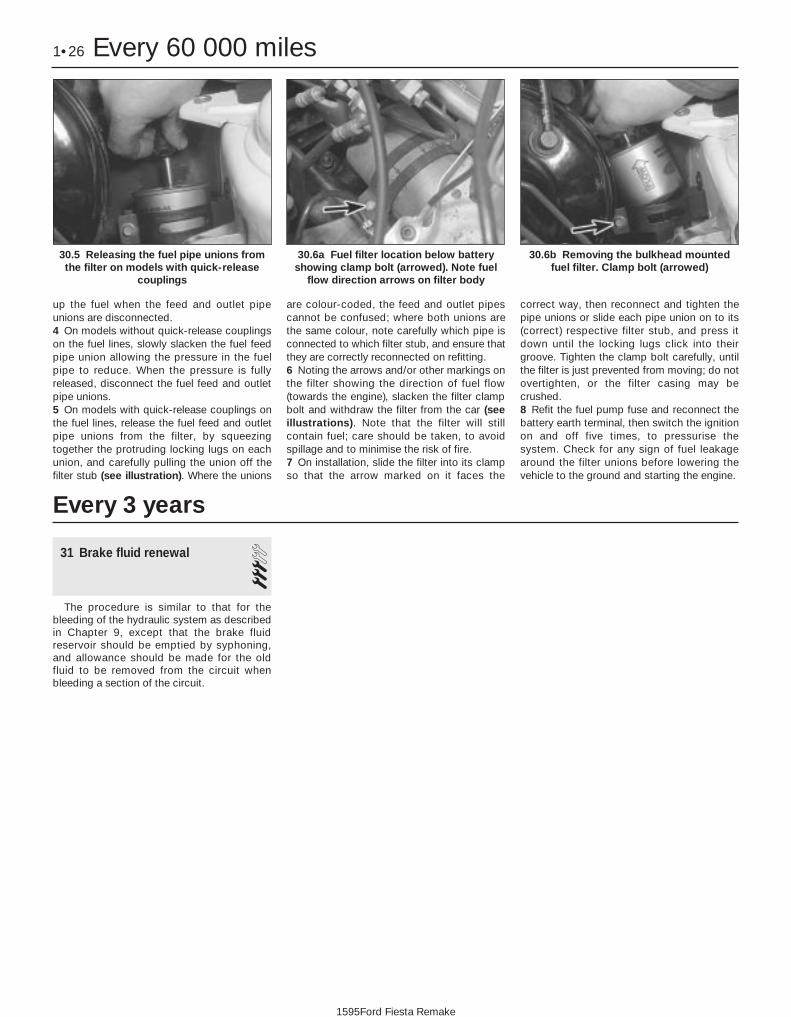
up the fuel when the feed and outlet pipeunions are disconnected.4 On models without quick-release couplingson the fuel lines, slowly slacken the fuel feedpipe union allowing the pressure in the fuelpipe to reduce. When the pressure is fullyreleased, disconnect the fuel feed and outletpipe unions.5 On models with quick-release couplings onthe fuel lines, release the fuel feed and outletpipe unions from the filter, by squeezingtogether the protruding locking lugs on eachunion, and carefully pulling the union off thefilter stub (see illustration). Where the unions
are colour-coded, the feed and outlet pipescannot be confused; where both unions arethe same colour, note carefully which pipe isconnected to which filter stub, and ensure thatthey are correctly reconnected on refitting.6 Noting the arrows and/or other markings onthe filter showing the direction of fuel flow(towards the engine), slacken the filter clampbolt and withdraw the filter from the car (seeillustrations). Note that the filter will stillcontain fuel; care should be taken, to avoidspillage and to minimise the risk of fire.7 On installation, slide the filter into its clampso that the arrow marked on it faces the
correct way, then reconnect and tighten thepipe unions or slide each pipe union on to its(correct) respective filter stub, and press itdown until the locking lugs click into theirgroove. Tighten the clamp bolt carefully, untilthe filter is just prevented from moving; do notovertighten, or the filter casing may becrushed.8 Refit the fuel pump fuse and reconnect thebattery earth terminal, then switch the ignitionon and off five times, to pressurise thesystem. Check for any sign of fuel leakagearound the filter unions before lowering thevehicle to the ground and starting the engine.
1•26 Every 60 000 miles
30.6b Removing the bulkhead mountedfuel filter. Clamp bolt (arrowed)
30.6a Fuel filter location below batteryshowing clamp bolt (arrowed). Note fuel
flow direction arrows on filter body
30.5 Releasing the fuel pipe unions fromthe filter on models with quick-release
couplings
1595Ford Fiesta Remake
Every 3 years
31 Brake fluid renewal 3The procedure is similar to that for the
bleeding of the hydraulic system as describedin Chapter 9, except that the brake fluidreservoir should be emptied by syphoning,and allowance should be made for the oldfluid to be removed from the circuit whenbleeding a section of the circuit.

2A
1595Ford Fiesta Remake
GeneralEngine type . . . . . . . . . . . . . . . . . . . . . . . . . . . . . . . . . . . . . . . . . . . . . . . Four-cylinder, in-line overhead valveEngine code:
1.0 litre carburettor models . . . . . . . . . . . . . . . . . . . . . . . . . . . . . . . . . TLB1.1 litre carburettor models . . . . . . . . . . . . . . . . . . . . . . . . . . . . . . . . . GUE or GUD1.1 litre CFi fuel injection models . . . . . . . . . . . . . . . . . . . . . . . . . . . . G6A1.3 litre carburettor models . . . . . . . . . . . . . . . . . . . . . . . . . . . . . . . . . JBC1.3 litre CFi fuel injection models . . . . . . . . . . . . . . . . . . . . . . . . . . . . J6B
Capacity:1.0 litre models . . . . . . . . . . . . . . . . . . . . . . . . . . . . . . . . . . . . . . . . . . 999 cc1.1 litre models . . . . . . . . . . . . . . . . . . . . . . . . . . . . . . . . . . . . . . . . . . 1118 cc1.3 litre models . . . . . . . . . . . . . . . . . . . . . . . . . . . . . . . . . . . . . . . . . . 1297 cc
Bore:1.0 and 1.1 litre models . . . . . . . . . . . . . . . . . . . . . . . . . . . . . . . . . . . 68.68 mm1.3 litre models . . . . . . . . . . . . . . . . . . . . . . . . . . . . . . . . . . . . . . . . . . 73.96 mm
Stroke:1.0 litre models . . . . . . . . . . . . . . . . . . . . . . . . . . . . . . . . . . . . . . . . . . 67.40 mm1.1 and 1.3 litre models . . . . . . . . . . . . . . . . . . . . . . . . . . . . . . . . . . . 75.48 mm
Compression ratio:Carburettor models . . . . . . . . . . . . . . . . . . . . . . . . . . . . . . . . . . . . . . . 9.5:1CFi fuel injection models . . . . . . . . . . . . . . . . . . . . . . . . . . . . . . . . . . . 8.8:1
Firing order . . . . . . . . . . . . . . . . . . . . . . . . . . . . . . . . . . . . . . . . . . . . . . . 1-2-4-3 (No 1 cylinder at timing chain end)Direction of crankshaft rotation . . . . . . . . . . . . . . . . . . . . . . . . . . . . . . . Clockwise (seen from right-hand side of vehicle)
ValvesValve clearance (cold):
Inlet . . . . . . . . . . . . . . . . . . . . . . . . . . . . . . . . . . . . . . . . . . . . . . . . . . . 0.20 mmExhaust . . . . . . . . . . . . . . . . . . . . . . . . . . . . . . . . . . . . . . . . . . . . . . . . 0.30 mm
Chapter 2 Part A:HCS engine in-car repair procedures
Auxiliary drivebelt check and renewal . . . . . . . . . . . . . . .See Chapter 1Compression test - description and interpretation . . . . . . . . . . . . . . 2Crankshaft oil seals - renewal . . . . . . . . . . . . . . . . . . . . . . . . . . . . . . 14Crankshaft pulley - removal and refitting . . . . . . . . . . . . . . . . . . . . . 8Cylinder head - removal and refitting . . . . . . . . . . . . . . . . . . . . . . . . 7Cylinder head rocker cover - removal and refitting . . . . . . . . . . . . . . 4Cylinder head rocker gear - removal, inspection and refitting . . . . . 6Engine oil and filter renewal . . . . . . . . . . . . . . . . . . . . . . .See Chapter 1Engine oil level check . . . . . . . . . . . . . . . . . . . . . .See “Weekly Checks”Engine/transmission mountings - inspection and renewal . . . . . . . . 15
Flywheel - removal, inspection and refitting . . . . . . . . . . . . . . . . . . . 16General information . . . . . . . . . . . . . . . . . . . . . . . . . . . . . . . . . . . . . . 1Oil pump - dismantling, inspection and reassembly . . . . . . . . . . . . . 13Oil pump - removal and refitting . . . . . . . . . . . . . . . . . . . . . . . . . . . . 12Sump - removal and refitting . . . . . . . . . . . . . . . . . . . . . . . . . . . . . . . 11Timing chain cover - removal and refitting . . . . . . . . . . . . . . . . . . . . 9Timing chain, sprockets and tensioner - removal, inspection
and refitting . . . . . . . . . . . . . . . . . . . . . . . . . . . . . . . . . . . . . . . . . . 10Top Dead Centre (TDC) for No 1 piston - locating . . . . . . . . . . . . . . 3Valve clearances - checking and adjustment . . . . . . . . . . . . . . . . . . 5
2A•1
Specifications
Contents
Easy, suitable fornovice with littleexperience
Fairly easy, suitablefor beginner withsome experience
Fairly difficult,suitable for competentDIY mechanic
Difficult, suitable forexperienced DIYmechanic
Very difficult,suitable for expert DIYor professional
Degrees of difficulty
54321

LubricationEngine oil type/specification . . . . . . . . . . . . . . . . . . . . . . . . . . . . . . . . . . See “Lubricants, fluids and tyre pressures”Engine oil capacity . . . . . . . . . . . . . . . . . . . . . . . . . . . . . . . . . . . . . . . . . See “Lubricants, fluids and tyre pressures”Oil pressure:
At idle speed . . . . . . . . . . . . . . . . . . . . . . . . . . . . . . . . . . . . . . . . . . . . 0.60 barsAt 2000 rpm . . . . . . . . . . . . . . . . . . . . . . . . . . . . . . . . . . . . . . . . . . . . 1.50 bars
Oil pump clearances:Outer rotor-to-body . . . . . . . . . . . . . . . . . . . . . . . . . . . . . . . . . . . . . . 0.14 to 0.26 mmInner rotor-to-outer rotor . . . . . . . . . . . . . . . . . . . . . . . . . . . . . . . . . . 0.051 to 0.127 mmRotor endfloat . . . . . . . . . . . . . . . . . . . . . . . . . . . . . . . . . . . . . . . . . . . 0.025 to 0.06 mm
Torque wrench settings Nm lbf ftCamshaft thrust plate bolts . . . . . . . . . . . . . . . . . . . . . . . . . . . . . . . . . . 5 4Camshaft sprocket bolt . . . . . . . . . . . . . . . . . . . . . . . . . . . . . . . . . . . . . 18 13Crankshaft pulley bolt . . . . . . . . . . . . . . . . . . . . . . . . . . . . . . . . . . . . . . . 115 85Rocker shaft pedestal bolts . . . . . . . . . . . . . . . . . . . . . . . . . . . . . . . . . . 43 32Flywheel bolts . . . . . . . . . . . . . . . . . . . . . . . . . . . . . . . . . . . . . . . . . . . . . 67 49Sump:
Stage 1 . . . . . . . . . . . . . . . . . . . . . . . . . . . . . . . . . . . . . . . . . . . . . . . . 7 5Stage 2 . . . . . . . . . . . . . . . . . . . . . . . . . . . . . . . . . . . . . . . . . . . . . . . . 9 7Stage 3 (with engine warm) . . . . . . . . . . . . . . . . . . . . . . . . . . . . . . . . 9 7
Oil pressure switch . . . . . . . . . . . . . . . . . . . . . . . . . . . . . . . . . . . . . . . . . 14 10Cylinder head bolts (may be re-used once only):
Stage 1 . . . . . . . . . . . . . . . . . . . . . . . . . . . . . . . . . . . . . . . . . . . . . . . . 30 22Stage 2 . . . . . . . . . . . . . . . . . . . . . . . . . . . . . . . . . . . . . . . . . . . . . . . . Angle-tighten a further 90ºStage 3 . . . . . . . . . . . . . . . . . . . . . . . . . . . . . . . . . . . . . . . . . . . . . . . . Angle-tighten a further 90º
Timing chain tensioner . . . . . . . . . . . . . . . . . . . . . . . . . . . . . . . . . . . . . . 8 6Timing chain cover . . . . . . . . . . . . . . . . . . . . . . . . . . . . . . . . . . . . . . . . . 9 7Crankshaft rear oil seal housing . . . . . . . . . . . . . . . . . . . . . . . . . . . . . . . 18 13Rocker cover bolts . . . . . . . . . . . . . . . . . . . . . . . . . . . . . . . . . . . . . . . . . 5 4Oil pump . . . . . . . . . . . . . . . . . . . . . . . . . . . . . . . . . . . . . . . . . . . . . . . . . 18 13Oil pump cover . . . . . . . . . . . . . . . . . . . . . . . . . . . . . . . . . . . . . . . . . . . . 9 7Engine mountings:
Engine mounting (right-hand):Bolt to body (in wheel arch) . . . . . . . . . . . . . . . . . . . . . . . . . . . . . . 41 to 58 30 to 43Nut to body (by suspension strut) . . . . . . . . . . . . . . . . . . . . . . . . . . 41 to 58 30 to 43Bracket to cylinder block . . . . . . . . . . . . . . . . . . . . . . . . . . . . . . . . 54 to 72 40 to 53Rubber insulator to bracket . . . . . . . . . . . . . . . . . . . . . . . . . . . . . . 71 to 95 52 to 70
Transmission mounting fasteners . . . . . . . . . . . . . . . . . . . . . . . . . . . . Refer to Chapter 7A or 7BNote: Refer to Part D of this Chapter for remaining torque wrench settings.
2A•2 HCS engine in-car repair procedures
1595Ford Fiesta Remake
1 General information
How to use this ChapterThis Part of Chapter 2 is devoted to repair
procedures possible while the engine is stillinstalled in the vehicle, and includes only theSpecifications relevant to those procedures.Similar information concerning the 1.4 and 1.6 litre CVH and PTE engines, and the 1.6and 1.8 litre Zetec engines, will be found inParts B and C of this Chapter respectively.Since these procedures are based on theassumption that the engine is installed in thevehicle, if the engine has been removed fromthe vehicle and mounted on a stand, some of the preliminary dismantling steps outlinedwill not apply.
Information concerning engine/transmissionremoval and refitting, and engine overhaul, canbe found in Part D of this Chapter, which alsoincludes the Specifications relevant to thoseprocedures.
Engine descriptionThe engine is an overhead valve, water-
cooled, four cylinder in-line design,designated HCS (High Compression Swirl).The engine is mounted transversely at thefront of the vehicle together with thetransmission to form a combined power unit.
The crankshaft is supported in three or fiveshell-type main bearings. The connecting rodbig-end bearings are also split shell-type, andare attached to the pistons by interference-fitgudgeon pins. Each piston is fitted with twocompression rings and one oil control ring.
The camshaft, which runs on bearingswithin the cylinder block, is chain-driven fromthe crankshaft, and operates the valves viapushrods and rocker arms. The valves areeach closed by a single valve spring, andoperate in guides integral in the cylinder head.
The oil pump is mounted externally on thecrankcase, incorporates a full-flow oil filter,and is driven by a skew gear on the camshaft.On carburettor versions, the fuel pump is alsodriven from the camshaft, via an eccentriclobe.
Repair operations possible withthe engine in the car
The following work can be carried out withthe engine in the car:a) Compression pressure - testing.b) Cylinder head rocker cover - removal
and refitting.c) Valve clearances - adjustment.d) Rocker shaft assembly - removal,
inspection and refitting.e) Cylinder head - removal and refittingf) Cylinder head and pistons -
decarbonising.g) Crankshaft pulley - removal and refitting.h) Crankshaft oil seals - renewal.i) Timing chain, sprockets and tensioner -
removal, inspection and refitting.j) Oil filter renewal.k) Oil pump - removal and refitting.l) Sump - removal and refitting.m) Flywheel - removal, inspection and
refitting.n) Engine/transmission mountings -
inspection and renewal.Note: It is possible to remove the pistons and

connecting rods (after removing the cylinderhead and sump) without removing the engine.However, this is not recommended. Work ofthis nature is more easily and thoroughlycompleted with the engine on the bench, asdescribed in Chapter 2D.
2 Compression test -description and interpretation 2
1 When engine performance is down, or ifmisfiring occurs which cannot be attributed tothe ignition or fuel systems, a compressiontest can provide diagnostic clues as to theengine’s condition. If the test is performedregularly, it can give warning of trouble beforeany other symptoms become apparent.2 The engine must be fully warmed-up tonormal operating temperature, the oil levelmust be correct and the battery must be fullycharged. The aid of an assistant will also berequired.3 On fuel injection engines, refer to Chap-ter 12 and remove the fuel pump fuse from thefusebox. Now start the engine and allow it torun until it stalls.4 Disable the ignition system bydisconnecting the multi-plug from the DIS orE-DIS ignition coil. Remove all the spark plugswith reference to Chapter 1 if necessary.5 Fit a compression tester to the No 1cylinder spark plug hole - the type of testerwhich screws into the plug thread is to bepreferred.6 Arrange for an assistant to hold theaccelerator pedal fully depressed to the floor,while at the same time cranking the engineover for several seconds on the starter motor.Observe the compression gauge reading. Thecompression will build up fairly quickly in ahealthy engine. Low compression on the firststroke, followed by gradually-increasingpressure on successive strokes, indicatesworn piston rings. A low compression on thefirst stroke which does not rise on successivestrokes, indicates leaking valves or a blownhead gasket (a cracked cylinder head couldalso be the cause). Deposits on the undersideof the valve heads can also cause lowcompression. Record the highest gaugereading obtained, then repeat the procedurefor the remaining cylinders.7 Due to the variety of testers available, andthe fluctuation in starter motor speed whencranking the engine, different readings are often obtained when carrying out the compression test. For this reason, actualcompression pressure figures are not quotedby Ford. However, the most important factoris that the compression pressures are uniformin all cylinders, and that is what this test ismainly concerned with.8 Add some engine oil (about three squirtsfrom a plunger type oil can) to each cylinderthrough the spark plug holes, and then repeatthe test.
9 If the compression increases after the oil isadded, it is indicative that the piston rings aredefinitely worn. If the compression does notincrease significantly, the leakage is occurringat the valves or the head gasket. Leakagepast the valves may be caused by burnedvalve seats and/or faces, or warped, crackedor bent valves.10 If two adjacent cylinders have equally lowcompressions, it is most likely that the headgasket has blown between them. Theappearance of coolant in the combustionchambers or on the engine oil dipstick wouldverify this condition.11 If one cylinder is about 20 percent lowerthan the other, and the engine has a slightlyrough idle, a worn lobe on the camshaft couldbe the cause.12 On completion of the checks, refit thespark plugs and reconnect the HT leads andthe ignition coil plug. Refit the fuel pump fuseto the fusebox.
3 Top Dead Centre (TDC) forNo 1 piston - locating 2
1 Top dead centre (TDC) is the highest pointof the cylinder that each piston reaches as thecrankshaft turns. Each piston reaches its TDCposition at the end of its compression stroke,and then again at the end of its exhauststroke. For the purpose of engine timing, TDCat the end of the compression stroke for No 1piston is used. On the HCS engine, No 1cylinder is at the crankshaft pulley/timingchain end of the engine. Proceed as follows.2 Ensure that the ignition is switched off.Disconnect the HT leads from the spark plugs,then unscrew and remove the plugs asdescribed in Chapter 1.3 Turn the engine over by hand (using aspanner on the crankshaft pulley) to the pointwhere the timing mark on the crankshaftpulley aligns with the TDC (0) mark or TDCreference pointer on the timing cover (seeillustration). As the pulley mark nears thetiming mark, the No 1 piston is simultaneouslyapproaching the top of its cylinder. To ensurethat it is on its compression stroke, place afinger over the No 1 cylinder plug hole, and
feel to ensure that air pressure exits from thecylinder as the piston reaches the top of itsstroke.4 A further check to ensure that the piston ison its compression stroke can be made byfirst removing the air cleaner (refer to therelevant Part of Chapter 4), then unbolting andremoving the rocker cover, so that themovement of the valves and rockers can beobserved.5 With the TDC timing marks on thecrankshaft pulley and timing cover inalignment, rock the crankshaft back and fortha few degrees each side of this position, andobserve the action of the valves and rockersfor No 1 cylinder. When No 1 piston is at theTDC firing position, the inlet and exhaust valveof No 1 cylinder will be fully closed, but thecorresponding valves of No 4 cylinder will beseen to rock open and closed.6 If the inlet and exhaust valves of No 1cylinder are seen to rock whilst those of No 4 cylinder are shut, the crankshaft willneed to be turned one full rotation to bring No 1 piston up to the top of its cylinder on thecompression stroke.7 Once No 1 cylinder has been positioned atTDC on the compression stroke, TDC for anyof the other cylinders can then be located byrotating the crankshaft clockwise (in itsnormal direction of rotation), 180º at a time,and following the firing order (seeSpecifications).
4 Cylinder head rocker cover -removal and refitting 1
Removal1 Where necessary for access, remove the aircleaner as described in the relevant Part ofChapter 4.2 Detach the HT leads from the spark plugs.Pull on the connector of each lead (not thelead itself), and note the order of fitting.3 Remove the engine oil filler cap andbreather hose (where fitted).4 Unscrew the four retaining bolts, and lift therocker cover clear of the cylinder head.Remove the gasket.
HCS engine in-car repair procedures 2A•3
3.3 Timing mark on the crankshaft pulley aligned with the TDC (0) mark on the timingcover
2A
1595Ford Fiesta Remake

Refitting5 Thoroughly clean the rocker cover, andscrape away any traces of old gasketremaining on the cover and cylinder headmating surfaces.6 Fit a new gasket to the rocker cover, thenrefit the rocker cover (see illustrations).Tighten the cover retaining bolts to thespecified torque wrench setting, in a diagonalsequence.7 Reconnect the HT leads, and refit the aircleaner as described in Chapter 4.
5 Valve clearances - checking and adjustment 2
Note: The valve clearances must be checkedand adjusted only when the engine is cold.1 The importance of having the valveclearances correctly adjusted cannot beoverstressed, as they vitally affect theperformance of the engine. If the clearancesare too big, the engine will be noisy(characteristic rattling or tapping noises) andengine efficiency will be reduced, as thevalves open too late and close too early. Amore serious problem arises if the clearancesare too small, however. If this is the case, thevalves may not close fully when the engine ishot, resulting in serious damage to the engine(eg. burnt valve seats and/or cylinder headwarping/cracking). The clearances arechecked and adjusted as follows.2 Set the engine to TDC for No 1 piston, asdescribed in Section 3.3 Remove the rocker cover as described inSection 4.4 Starting from the thermostat end of thecylinder head, the valves are numbered asfollows:
Valve No Cylinder No1 - Exhaust 12 - Inlet 13 - Exhaust 24 - Inlet 25 - Inlet 36 - Exhaust 37 - Inlet 48 - Exhaust 4
5 Adjust the valve clearances following thesequence given in the following table. Turnthe crankshaft pulley 180º (half a turn) afteradjusting each pair of valve clearances.
Valves “rocking” Valves to adjust7 and 8 1 (exhaust), 2 (inlet)5 and 6 3 (exhaust), 4 (inlet)1 and 2 8 (exhaust), 7 (inlet) 3 and 4 6 (exhaust), 5 (inlet)
6 The clearances for the inlet and exhaustvalves differ (refer to the Specifications). Use afeeler gauge of the appropriate thickness tocheck each clearance between the end of thevalve stem and the rocker arm (seeillustration). The gauge should be a firmsliding fit between the valve and rocker arm.Where adjustment is necessary, turn theadjuster bolt as required with a ring spannerto set the clearance to that specified. Theadjuster bolts are of stiff-thread type, andrequire no locking nut.7 On completion, refit the rocker cover asdescribed in Section 4.
6 Cylinder head rocker gear -removal, inspection andrefitting
2Removal1 Remove the rocker cover as described inSection 4.2 Unscrew the four retaining bolts, and lift therocker gear assembly from the cylinder head.As the assembly is withdrawn, ensure that thepushrods remain seated in their positions inthe engine.
Inspection3 To dismantle the rocker shaft assembly,extract the split pin from one end of the shaft,then withdraw the spring and plain washersfrom the shaft.4 Slide off the rocker arms, the supportpedestals and coil springs from the shaft, but
take care to keep them in their original orderof fitting (see illustration).5 Clean the respective components, andinspect them for signs of excessive wear ordamage. Check that the oil lubrication holes inthe shaft are clear.6 Check the rocker shaft and arm pads whichbear on the valve stem end faces for wear andscoring, and check each rocker arm on theshaft for excessive wear. Renew anycomponents as necessary.
Refitting7 Apply clean engine oil to the rocker shaftprior to reassembling.
2A•4 HCS engine in-car repair procedures
6.4 Rocker shaft partially dismantled forinspection
5.6 Adjusting the valve clearances4.6b Refitting the rocker cover4.6a Engage tags of rocker cover gasketinto the cut-outs in the cover
1595Ford Fiesta Remake
Turning the engine will beeasier if the spark plugs areremoved first - see Chapter 1.
If the pushrods are to be removed,keep them in the correct order of fittingby labelling them 1 to 8, starting fromthe thermostat end of the cylinderhead, or locate them in a card.

8 Reassemble in the reverse order ofdismantling. Make sure that the “flat” on therear end of the rocker shaft is to the same sideas the rocker arm adjusting screws (closest tothe thermostat end of the cylinder head whenfitted) (see illustration). This is essential forthe correct lubrication of the cylinder headcomponents.9 Refit the rocker shaft assembly. As it isfitted, ensure that the rocker adjuster screwsengage with their corresponding pushrods.10 Refit the rocker shaft retaining bolts,hand-tighten them and then tighten them tothe specified torque wrench setting. As theyare tightened, some of the rocker arms willapply pressure to the ends of the valve stems,and some of the rocker pedestals will notinitially be in contact with the cylinder head -these should pull down as the bolts aretightened to their specified torque. If for anyreason they do not, avoid the temptation toovertighten in order to pull them into position;loosen off the bolts, and check the cause ofthe problem. It may be that the rocker adjusterscrews require loosening off in order to allowthe assembly to be tightened down asrequired.11 Adjust the valve clearances as describedin Section 5.
7 Cylinder head - removal and refitting 3
RemovalNote: The following procedure describesremoval and refitting of the cylinder headcomplete with inlet and exhaust manifolds. Ifwished, the manifolds may be removed first,as described in the relevant Part of Chapter 4,and the cylinder head then removed on itsown.1 On fuel injection engines, depressurise thefuel system as described in Chapter 4, Part B.2 Disconnect the battery negative (earth) lead(refer to Chapter 5A, Section 1).3 Refer to Chapter 4A or 4B as applicableand remove the air cleaner.4 Refer to Section 4 and remove the rockercover.
5 Refer to Chapter 1 and drain the coolingsystem.6 Disconnect the hoses from the thermostathousing.7 Disconnect the heater (coolant) hoses fromthe inlet manifold and CFi unit, whereapplicable.
8 Disconnect the accelerator and chokecables as applicable (see Chapter 4A or 4B).9 Disconnect the vacuum and breather hosesfrom the carburettor/CFi unit, and inletmanifold as applicable.10 Disconnect the fuel feed and return linesat the carburettor, or at the quick-releasecouplings, then unclip the fuel hoses from theinlet manifold; use rag to soak up any spiltfuel.11 Disconnect the HT leads from the sparkplugs and the support bracket. Unscrew andremove the spark plugs.12 Disconnect the electrical leads from thetemperature gauge sender, radiator coolingfan, the engine coolant temperature sender,and the anti-run-on (anti-dieselling) valve atthe carburettor.13 Disconnect the remaining wiring multi-plugs from the engine sensors at the inletmanifold and from the oxygen sensor (wherefitted) in the exhaust manifold or downpipe.14 On vehicles equipped with a pulse-airsystem, remove the pulse-air piping and filterassembly as described in Chapter 4E.15 Chock the rear wheels then jack up thefront of the car and support it on axle stands(see “Jacking and Vehicle Support”).16 Undo the retaining nuts and bolts, anddisconnect the exhaust downpipe from themanifold. Remove the flange gasket. (Notethat both the gasket and the joint self-lockingnuts must be renewed.) To prevent theexhaust system from being strained, tie thedownpipe up using strong wire or a length ofcord to support it. Lower the vehicle.17 Undo the four retaining bolts and lift clearthe rocker gear assembly from the cylinderhead.18 Lift out the pushrods. Keep them in orderof fitting by labelling them 1 to 8, starting fromthe thermostat end of the cylinder head.Alternatively, push them through a piece ofcard in their fitted sequence.19 Progressively unscrew and loosen off thecylinder head retaining bolts in the reversesequence to that shown for tightening (seeillustration 7.27a). When they are all
loosened off, remove the bolts, then lift thecylinder head clear and remove the gasket. Ifit is stuck, tap it upwards using a hammer andblock of wood. Do not try to turn it, as it islocated by dowels; make no attemptwhatsoever to prise it free using a screwdriverinserted between the block and head faces.The gasket must always be renewed; it shouldbe noted that the cylinder head retaining boltsmay be re-used, but only once. They shouldbe marked accordingly with a punch or paintmark. If there is any doubt as to how manytimes the bolts have been used, they must berenewed.20 To dismantle/overhaul the cylinder head,refer to Part D of this Chapter. It is normal forthe cylinder head to be decarbonised and thevalves to be reground whenever the head isremoved.
Preparation for refitting21 The mating faces of the cylinder head andcylinder block must be perfectly clean beforerefitting the head. Use a hard plastic or woodscraper to remove all traces of gasket andcarbon; also clean the piston crowns. Takeparticular care during the cleaning operations,as aluminium alloy is easily damaged. Also,make sure that the carbon is not allowed toenter the oil and water passages - this isparticularly important for the lubricationsystem, as carbon could block the oil supplyto the engine’s components. Using adhesivetape and paper, seal the water, oil and boltholes in the cylinder block.
22 Check the mating surfaces of the cylinderblock and the cylinder head for nicks, deepscratches and other damage. If slight, theymay be removed carefully with a file, but ifexcessive, machining may be the onlyalternative to renewal.23 If warpage of the cylinder head gasketsurface is suspected, use a straight-edge tocheck it for distortion. Refer to Part D of thisChapter if necessary.24 Clean the threads of the cylinder headbolts or fit new ones (as applicable) and cleanout the bolt holes in the block. Screwing a boltinto an oil-filled hole can (in extreme cases)cause the block to fracture, due to thehydraulic pressure.
Refitting25 Check that the new cylinder head gasketis the same type as the original, and that the“TOP” (or “OBEN”) marking is facingupwards. Locate the new cylinder head
HCS engine in-car repair procedures 2A•5
6.8 Flat on the rocker shaft (arrowed) tosame side as rocker arm adjusting screws
2A
1595Ford Fiesta Remake
Whenever you disconnectany vacuum lines, coolant oremissions hoses, wiringconnectors and fuel lines,
always label them clearly, so that theycan be correctly reassembled. Maskingtape and/or a touch-up paint applicatorwork well for marking items. Takeinstant photos, or sketch the locationsof components and brackets.
To prevent carbon enteringthe gap between the pistonsand bores, smear a littlegrease in the gap. After
cleaning each piston, use a small brushto remove all traces of grease andcarbon from the gap, then wipe awaythe remainder with a clean rag.

gasket onto the top face of the cylinder blockand over the dowels. Ensure that it is correctlyaligned with the coolant passages andoilways (see illustration).26 Lower the cylinder head carefully intoposition, then insert the retaining bolts andhand-tighten them.27 Tightening of the cylinder head bolts mustdone in three stages, and in the correctsequence (see illustration). First tighten all ofthe bolts in the sequence shown to the Stage 1 torque setting (see illustration).When all of the bolts are tightened to theStage 1 setting, further tighten each bolt (insequence) through the Stage 2 specifiedangle of rotation. When the second stagetightening is completed on all of the bolts,further tighten them to the Stage 3 anglesetting (in sequence) to complete. Wherepossible, use an angular torque setting gaugeattachment tool for accurate tightening ofstages two and three (see illustration).28 Lubricate the pushrods with clean engineoil, and then insert them into their originallocations in the engine.29 Refit the rocker shaft assembly. As it isfitted, ensure that the rocker adjuster screwsengage with their corresponding pushrods.30 Refit the rocker shaft retaining bolts,hand-tighten them and then tighten them to the specified torque wrench setting. Asthey are tightened, some of the rocker armswill apply pressure to the ends of the valvestems, and some of the rocker pedestals willnot initially be in contact with the cylinder
head - these should pull down as the bolts aretightened. If for any reason they do not, avoidthe temptation to overtighten in order to pullthem into position; loosen off the bolts, andcheck the cause of the problem. It may bethat the rocker adjuster screws requireloosening off in order to allow the assembly tobe tightened down as required.31 Adjust the valve clearances as describedin Section 5.32 Refit the rocker cover as described inSection 4.33 The remainder of the refitting procedure isa reversal of the removal process. Tighten allfastenings to their specified torque setting(where given). Refer to the appropriate Partsof Chapter 4 for details on reconnecting thefuel and exhaust system components. Ensurethat all coolant, fuel, vacuum and electricalconnections are securely made.34 On completion, refill the cooling systemand top-up the engine oil (see Chapter 1 and“Weekly Checks”). When the engine isrestarted, check for any sign of fuel, oil and/orcoolant leakages from the various cylinderhead joints.
8 Crankshaft pulley - removal and refitting 2
Removal1 Disconnect the battery negative (earth) lead(refer to Chapter 5A, Section 1).2 Chock the rear wheels then jack up thefront of the car and support it on axle stands(see “Jacking and Vehicle Support”). Removethe right-hand front roadwheel.3 Remove the auxiliary drivebelt as describedin Chapter 1.4 Loosen off the crankshaft pulley retainingbolt. To prevent the crankshaft from turning,unbolt and remove the clutch housing coverplate. Lock the starter ring gear on theflywheel using a large screwdriver or similartool inserted through the cover plate aperture.Alternatively, remove the starter motor(Chapter 5A) and lock the ring gear throughthe starter motor aperture.
5 Fully unscrew the crankshaft pulley bolt,and withdraw the pulley from the front end ofthe crankshaft. If it does not pull off by hand,lever it free using a pair of suitable leverspositioned diagonally opposite each otherbehind the pulley.6 If required, the crankshaft front oil seal canbe renewed at this stage, as described inSection 14.
Refitting7 Refitting is a reversal of the removalprocedure ensuring that the pulley retainingbolt is tightened to the specified torquesetting.8 Refit the auxiliary drivebelt as described inChapter 1, and lower the vehicle to complete.
9 Timing chain cover - removal and refitting 2
Removal1 Remove the sump as described in Sec-tion 11.2 Remove the crankshaft pulley as describedin the previous Section.3 A combined timing cover and water pumpgasket is fitted during production; if this is stillin position, it will be necessary to drain thecooling system and remove the water pumpas described in Chapter 3. If the water pumpand/or the timing cover have been removed atany time, the single gasket used originally willhave been replaced by an individual gasketfor each component, in which case the waterpump can remain in position.4 Unscrew the retaining bolts, and carefullyprise free the timing chain cover.5 Clean the mating faces of the timing chaincover, and the engine.6 If necessary, renew the crankshaft front oilseal in the timing cover prior to refitting thecover (see Section 14).
Refitting7 Lightly lubricate the front end of thecrankshaft and the radial lip of the timingchain cover oil seal (already installed in the
2A•6 HCS engine in-car repair procedures
7.27c Cylinder head bolt tightening(Stages 2 and 3) using an angle gauge
7.27b Tightening the cylinder head bolts(Stage 1)
7.27a Cylinder head bolt tighteningsequence
7.25 Cylinder head gasket top-facemarking (“OBEN”)
1595Ford Fiesta Remake

cover). Using a new gasket, fit the timingchain cover, centring it with the aid of thecrankshaft pulley - lubricate the seal contactsurfaces beforehand. Refit and tighten theretaining bolts but, where applicable, leaveout the timing cover bolt which also securesthe water pump at this stage.8 Where applicable, refit the water pump asdescribed in Chapter 3.9 Refit the crankshaft pulley as described inthe previous Section.10 Refit the sump as described in Section 11.
10 Timing chain, sprockets andtensioner - removal,inspection and refitting
3Removal1 Remove the timing chain cover asdescribed in the previous Section.2 Remove the oil slinger from the front face ofthe crankshaft, noting its orientation (seeillustration).3 Retract the chain tensioner cam backagainst its spring pressure, then slide thechain tensioner arm from its pivot pin on thefront main bearing cap (see illustration).4 Unbolt and remove the chain tensioner.5 Bend back the lockplate tabs from thecamshaft sprocket bolts, then unscrew andremove the bolts.6 Withdraw the sprocket complete with thetiming chain.
Inspection7 Examine the teeth on the timing sprocketsfor any signs of excessive wear or damage.8 The timing chain should always be renewedduring a major engine overhaul. Slack linksand pins are indicative of a worn chain.Unless the chain is known to be relativelynew, it should be renewed.9 Examine the rubber cushion on thetensioner spring leaf. If grooved ordeteriorated, it must be renewed.
Refitting10 Commence reassembly by bolting thetiming chain tensioner into position. Checkthat the face of the tensioner cam is parallelwith the face of the cylinder block, ideallyusing a dial gauge. The maximum permissibleerror between the two measuring points is 0.2 mm. Release and turn the timing chaintensioner as required to achieve this (ifnecessary). Refer to the Specifications for thecorrect tightening torque.11 Turn the crankshaft so that the timingmark on its sprocket is directly in line with thecentre of the camshaft sprocket mountingflange.12 Engage the camshaft sprocket with thetiming chain, then engage the chain aroundthe teeth of the crankshaft sprocket. Push thecamshaft sprocket onto its mounting flange,and check that the sprocket retaining boltholes are in alignment (see illustration). Also
check that the timing marks of both sprocketsface each other. If required, turn thecamshaft/sprocket as required to achieve this.It may also be necessary to remove thecamshaft from the chain in order to repositionit in the required location in the chain to alignthe timing marks. This is a “trial and error”procedure, which must be continued until theexact alignment of the bolt holes and thetiming marks is made (see illustration).13 Insert and tighten the camshaft sprocketretaining bolts to the specified torque wrenchsetting. Bend up the tabs of the new lockplateto secure (see illustration).14 Retract the timing chain tensioner cam,and then slide the tensioner arm onto its pivotpin. Release the cam so that it bears on thearm.15 Refit the oil slinger to the front of thecrankshaft sprocket so that its convex sidefaces the sprocket.16 Refit the timing chain cover as describedin the previous Section.
11 Sump - removal and refitting 2
Removal1 Disconnect the battery negative (earth) lead(refer to Chapter 5A, Section 1).2 Refer Chapter 1 and drain the engine oil.Refit the sump drain plug.3 Undo the retaining nuts and detach theexhaust downpipe from the manifold flange.Note that the flange gasket should berenewed on reassembly. Allowing sufficientclearance for sump removal, tie the exhaustdownpipe up with a suitable length of wire orcord to prevent the system straining theinsulators. On catalytic converter-equippedvehicles, avoid straining the oxygen sensorwiring; if necessary, disconnect the sensor’smulti-plug.4 Remove the starter motor (see Chapter 5A).5 Undo the two retaining bolts and removethe clutch housing cover plate and, wherefitted, the auxiliary drivebelt lower cover frominside the right-hand wheel arch.
HCS engine in-car repair procedures 2A•7
10.12a Fit the timing chain to thecrankshaft and camshaft sprockets . . .
10.3 Chain tensioner arm removal fromthe pivot pin. Note tensioner retaining
bolts (arrowed)
10.2 Oil slinger removal from crankshaft
10.13 Bend locktabs against the camshaftretaining bolt heads to secure
10.12b . . . and check that the timingmarks on the sprockets are in alignment
2A
1595Ford Fiesta Remake

6 Undo the eighteen bolts securing the sumpto the base of the engine crankcase, thenprise free and lower the sump. If the sump isstuck tight to the engine, cut around theflange gasket with a sharp knife, then lightlytap and prise it free. Keep the sump upright asit is lowered, to prevent spillage of anyremaining oil in it. Also be prepared for oildrips from the crankcase when the sump isremoved.7 Remove any dirt and old gasket from thecontact faces of the sump and crankcase, andwash the sump out thoroughly before refitting.Check that the mating faces of the sump arenot distorted. Check that the oil pick-upstrainer is clear, cleaning it if necessary.
Refitting8 Clean the gasket location faces. Apply adab of sealing compound to the mating faceswhere the ends of each cork half-gasket areto be fitted (see illustration). Stick the newcork gaskets into position on the block face,using clean thick grease to retain them, thenlocate the new rubber gaskets into their slotsin the timing chain cover and rear oil sealcarrier. The lugs of the cork gasket halves fitunder the cut-outs in the rubber gaskets (seeillustration).9 Before offering up the sump, check that thegap between the sump and the oil baffle isbetween 2.0 and 3.8 mm (see illustration).
Do not use a dented or damaged sump, asthe indicated dimension is important forcorrect engine lubrication.10 Fit the sump into position, and fit theretaining bolts. Initially tighten them all finger-tight, then further tighten them in the sequenceshown through Stages 1 and 2, to the torquewrench settings specified (see illustration).Note that different tightening sequences arespecified for the tightening stages. Final (Stage 3) tightening is carried out after theengine has been started and warmed up.11 Refit the lower plate to the front face ofthe clutch housing and refit the auxiliarydrivebelt lower cover.12 Refit the starter motor.13 Check that the downpipe and manifoldmating faces are clean, then locate a newgasket and reconnect the exhaust downpipeto the manifold. Where applicable, use newself-locking nuts, and tighten securely.14 Check that the sump drain plug is fittedand tightened to the specified torque, thenlower the vehicle to the ground.15 Refill the engine with oil as described inChapter 1.16 Reconnect the battery, then start theengine and run it up to its normal operatingtemperature. Check that no oil leaks areevident around the sump joint.17 After the engine has warmed up forapproximately 15 minutes, switch it off.Tighten the sump bolts to the Stage 3 torquewrench setting given in the Specifications, inthe sequence shown in illustration 11.10.
12 Oil pump - removal and refitting 2
Removal1 The oil pump is externally-mounted, on therear-facing side of the crankcase.2 Chock the rear wheels then jack up thefront of the car and support it on axle stands(see “Jacking and Vehicle Support”).3 Unscrew and remove the oil filter cartridge.It should unscrew by hand, but will probablybe tight. Use a strap wrench to loosen it off, ifrequired. Catch any oil spillage in a suitablecontainer.4 Undo the three retaining bolts and withdrawthe oil pump from the engine (seeillustration).5 Clean all traces of the old gasket from themating surfaces of the pump and engine.
Refitting6 If the original oil pump has been dismantledand reassembled and is to be re-used, or if anew pump is to be fitted, it must first beprimed with engine oil prior to fitting. To dothis, turn its driveshaft and simultaneouslyinject clean engine oil into it.7 Locate a new gasket into position on thepump mounting flange, then insert the pump,engaging the drivegear as it is fitted (seeillustration). Fit the retaining bolts, andtighten to the specified torque wrench setting.
2A•8 HCS engine in-car repair procedures
12.7 Refitting the oil pump. Note the newgasket
12.4 Unscrewing the oil pump retainingbolts
11.10 Sump bolt tightening sequence -arrow indicates crankshaft pulley end of
engine
See Specifications for torque wrench settingsStage 1 - Tighten in alphabetical orderStage 2 - Tighten in numerical orderStage 3 - Tighten in alphabetical order
11.9 Sump (A) and oil baffle (B) clearancedetails
11.8b Lugs of cork gasket halves to fitunder the cut-outs in the rubber gaskets
11.8a Sump gasket fitting details at thetiming chain cover end (A) and the flywheel
end (B)
1595Ford Fiesta Remake

8 Fit a new oil filter into position on the oil pump body, as described in Chap-ter 1.9 Lower the vehicle to the ground, and top-up the engine oil as described in “WeeklyChecks”.
13 Oil pump - dismantling,inspection and reassembly 3
Dismantling1 To inspect the oil pump components forexcessive wear, undo the retaining bolts andremove the cover plate from the pump body.Remove the O-ring seal from the cover face(see illustration).2 Wipe the exterior of the pump housingclean housing.
Inspection3 Noting their orientation, extract and cleanthe rotors and the inner body of the pumphousing. Inspect them for signs of severescoring or excessive wear, which if evidentwill necessitate renewal of the completepump.4 Using feeler gauges, check the clearancesbetween the pump body and the outer rotor,the inner-to-outer rotor clearance, and theamount of rotor endfloat (see illustrations).
5 Check the drivegear for signs of excessivewear or damage.6 If the clearances measured are outside thespecified maximum clearances and/or thedrivegear is in poor condition, the completepump unit must be renewed.
Reassembly7 Refit the rotors into the pump (in theiroriginal orientation), lubricate the rotors andthe new O-ring seal with clean engine oil, andrefit the cover. Tighten the retaining bolts tothe specified torque wrench setting.
14 Crankshaft oil seals - renewal 3
Front oil seal1 Remove the crankshaft pulley as describedin Section 8.2 Using a suitable claw tool, extract the oilseal from the timing chain cover, but take carenot to damage the seal housing. As it isremoved, note the fitted orientation of the sealin the cover.3 Clean the oil seal housing in the timingchain cover. Lubricate the sealing lips of thenew seal and the crankshaft stub with cleanengine oil.4 Locate the new seal into position so that it
is squarely located on the crankshaft stub andin the housing, and is correctly orientated.Drift it into position using a large socket,another suitable tool, or the old seal, until thenew seal is flush with the edge of the timingchain cover.5 Lightly lubricate the rubbing surface of thecrankshaft pulley, then refit the pulley asdescribed in Section 8.
Rear oil seal6 Remove the flywheel as described inSection 16.7 Using a suitable claw tool, lever the sealfrom the rear seal housing (taking care not todamage the housing). As it is removed, notethe fitted orientation of the seal.8 Clean the seal housing, the crankshaft rear flange face and the flywheel matingsurface.9 One of two possible methods may be usedto insert the new oil seal, depending on thetools available.10 If Ford service tool No 21-011 is available,lubricate the crankshaft flange and the oil sealinner lip with clean engine oil. Position theseal onto the service tool (ensuring correctorientation), then press the seal into itshousing.11 If the service tool is not available, removethe engine sump (Section 11), then unscrewthe Torx-head bolts retaining the rear sealhousing in position, and remove the seal housing from the rear face of the cylinderblock. New gaskets will be required for boththe seal housing and the sump when refitting.Clean the seal housing seat and the matingsurfaces of the sump and the crankcase. To fitthe seal squarely into its housing withoutdamaging either component, place a flatblock of wood across the seal, then carefullytap the seal into position in the housing (seeillustration). Do not allow the seal to tilt as itis being fitted. Lubricate the crankshaft flangeand the oil seal inner lip with clean engine oil,then with a new gasket located on the sealhousing/crankcase face, fit the housing intoposition. Take care not damage the seal lipsas it is passed over the crankshaft rear flange
HCS engine in-car repair procedures 2A•9
13.4b Checking the inner rotor-to-outerrotor clearance
13.4a Checking the outer body-to-rotorclearance
13.1 Extract the O-ring from the groove inthe oil pump
14.11a Positioning the crankshaft rear oilseal in its housing
13.4c Checking the rotor endfloat
2A
1595Ford Fiesta Remake

(see illustration). Centralise the seal on theshaft, then insert and tighten the housingretaining bolts to the specified torque setting.Refit the sump with reference to Section 11.12 Check that the crankshaft rear flange and the flywheel mating faces are clean, thenrefit the flywheel as described in Section 16.
15 Engine/transmissionmountings - inspection andrenewal
2Inspection1 The engine/transmission mountings seldomrequire attention, but broken or deterioratedmountings should be renewed immediately, orthe added strain placed on the drivelinecomponents may cause damage or wear.2 During the check, the engine/transmissionmust be raised slightly, to remove its weightfrom the mountings.3 Chock the rear wheels then jack up thefront of the car and support it on axle stands(see “Jacking and Vehicle Support”). Positiona jack under the sump, with a large block ofwood between the jack head and the sump,then carefully raise the engine/transmissionjust enough to take the weight off themountings.4 Check the mountings to see if the rubber iscracked, hardened or separated from the
metal components. Sometimes, the rubberwill split right down the centre.5 Check for relative movement between eachmounting’s brackets and theengine/transmission or body (use a largescrewdriver or lever to attempt to move themountings). If movement is noted, lower theengine and check-tighten the mountingfasteners.
Renewal6 The engine mountings can be removed ifthe weight of the engine/transmission issupported by one of the following alternativemethods.7 Either support the weight of the assemblyfrom underneath using a jack and a suitablepiece of wood between the jack saddle andthe sump or transmission (to preventdamage), or from above by attaching a hoistto the engine. A third method is to use asuitable support bar with end pieces whichwill engage in the water channel each side ofthe bonnet lid aperture. Using an adjustable
hook and chain connected to the engine, theweight of the engine and transmission canthen be taken from the mountings.
Engine right-hand mounting8 Unscrew and remove the mounting sidebolt from under the right-hand wheel arch(see illustration).9 Unscrew and remove the mountingretaining nut and washer from the suspensionstrut cup retaining plate (see illustration).10 Undo the three bolts securing themounting unit to the cylinder block. Themounting unit and bracket can then belowered from the engine (see illustration).11 Unbolt and remove the mounting from itssupport bracket.
Transmission bearer and mountings12 Unscrew and remove the two nutssecuring the mountings (front and rear) to thetransmission bearer (see illustration).13 Support the transmission bearer, thenundo and remove the four retaining bolts fromthe floorpan, two at the front and two at the
2A•10 HCS engine in-car repair procedures
15.12 Exploded view of the transmission bearer mountings
15.10 Undo the three bolts securing themounting assembly to the cylinder block
and withdraw the mounting
15.9 Unscrew and remove the mountingretaining nut and washer from the
suspension strut cup retaining plate
15.8 Unscrew and remove the enginemounting side bolt (arrowed) from under
the wheel arch
14.11b Fitting the rear oil seal housingwith a new gasket in position on the rear
face of the cylinder block
1595Ford Fiesta Remake

rear, and lower the transmission bearer fromthe vehicle. Note plate fitment, as applicable,for reassembly.14 Unscrew the single nut securing eachmounting and its retainer to the transmissionsupport bracket, and remove. Thetransmission support brackets are fixedexternally to the transmission casing and donot need to be removed for this operation.
All mountings15 Refitting of all mountings is a reversal ofremoval. Make sure that the original sequenceof assembly of washers and plates ismaintained.16 Do not fully tighten any mounting boltsuntil they are all located. As the mountingbolts and nuts are tightened, check that themounting rubbers do not twist.
16 Flywheel - removal, inspectionand refitting 3
Refitting1 Remove the transmission as described inChapter 7A, then remove the clutch asdescribed in Chapter 6.
2 Unscrew the six retaining bolts, and removethe flywheel from the rear end flange of thecrankshaft - take care not to drop theflywheel, as it is heavy. A tool similar to thatshown in illustration 16.5 can be fitted toprevent the flywheel/crankshaft from rotatingas the bolts are removed. If on removal, theretaining bolts are found to be in poorcondition (stretched threads, etc) they mustbe renewed.
Inspection3 Inspect the starter ring gear on the flywheelfor any broken or excessively-worn teeth. Ifevident, the ring gear must be renewed; this isa task best entrusted to a Ford dealer or acompetent garage. Alternatively, obtain acomplete new flywheel.4 The clutch friction surface on the flywheelmust be carefully inspected for grooving orhairline cracks (caused by overheating). Ifthese conditions are evident, it may bepossible to have the flywheel surface-groundto renovate it, providing that the balance isnot upset. Regrinding is a task for anautomotive engineer. If surface-grinding is notpossible, the flywheel must be renewed.
Refitting5 Check that the mating faces of the flywheel
and the crankshaft are clean before refitting.Lubricate the threads of the retaining boltswith engine oil before they are screwed intoposition. Locate the flywheel onto thecrankshaft, and insert the bolts. Hand-tightenthem initially, then tighten them in aprogressive sequence to the specified torquewrench setting (see illustration).6 Refit the clutch as described in Chapter 6and the transmission as described in Chap-ter 7A.
HCS engine in-car repair procedures 2A•11
16.5 Tightening the flywheel retainingbolts to the specified torque
Note the “peg” tool (arrowed) locking the ringgear teeth to prevent the flywheel/crankshaft
from rotating
2A
1595Ford Fiesta Remake

2A•12 HCS engine in-car repair procedures
1595Ford Fiesta Remake
Notes

2B
1595Ford Fiesta Remake
GeneralEngine type . . . . . . . . . . . . . . . . . . . . . . . . . . . . . . . . . . . . . . . . . . . . . . . Four-cylinder, in-line overhead camshaftEngine code:
1.4 litre CVH engine:Carburettor models . . . . . . . . . . . . . . . . . . . . . . . . . . . . . . . . . . . . . FUF or FUGCFi fuel injection models . . . . . . . . . . . . . . . . . . . . . . . . . . . . . . . . . F6E
1.4 litre PTE engine . . . . . . . . . . . . . . . . . . . . . . . . . . . . . . . . . . . . . . . F4A1.6 litre CVH engine:
Carburettor models . . . . . . . . . . . . . . . . . . . . . . . . . . . . . . . . . . . . . LUHEFi fuel injection models . . . . . . . . . . . . . . . . . . . . . . . . . . . . . . . . . LJC or LJDTurbo models . . . . . . . . . . . . . . . . . . . . . . . . . . . . . . . . . . . . . . . . . LHA
Capacity:1.4 litre CVH and PTE engines . . . . . . . . . . . . . . . . . . . . . . . . . . . . . . 1392 cc1.6 litre CVH engine . . . . . . . . . . . . . . . . . . . . . . . . . . . . . . . . . . . . . . 1596 cc
Bore:1.4 litre CVH and PTE engines . . . . . . . . . . . . . . . . . . . . . . . . . . . . . . 77.24 mm1.6 litre CVH engine . . . . . . . . . . . . . . . . . . . . . . . . . . . . . . . . . . . . . . 79.96 mm
Stroke:1.4 litre CVH and PTE engines . . . . . . . . . . . . . . . . . . . . . . . . . . . . . . 74.30 mm1.6 litre CVH engine . . . . . . . . . . . . . . . . . . . . . . . . . . . . . . . . . . . . . . 79.52 mm
Compression ratio:1.4 litre CVH carburettor engine . . . . . . . . . . . . . . . . . . . . . . . . . . . . . 9.5:11.4 litre CVH CFi fuel injection engine . . . . . . . . . . . . . . . . . . . . . . . . 8.5:11.4 litre PTE engine . . . . . . . . . . . . . . . . . . . . . . . . . . . . . . . . . . . . . . . 9.5:11.6 litre CVH engine:
Carburettor models . . . . . . . . . . . . . . . . . . . . . . . . . . . . . . . . . . . . . 9.5:1EFi fuel injection models . . . . . . . . . . . . . . . . . . . . . . . . . . . . . . . . . 9.75:1Turbo models . . . . . . . . . . . . . . . . . . . . . . . . . . . . . . . . . . . . . . . . . 8.0:1
Firing order . . . . . . . . . . . . . . . . . . . . . . . . . . . . . . . . . . . . . . . . . . . . . . . 1-3-4-2 (No 1 cylinder at timing belt end)Direction of crankshaft rotation . . . . . . . . . . . . . . . . . . . . . . . . . . . . . . . Clockwise (seen from right-hand side of vehicle)
Chapter 2 Part B:CVH and PTE engine in-car repair procedures
Auxiliary drivebelt check and renewal . . . . . . . . . . . . . . .See Chapter 1Camshaft oil seal - renewal . . . . . . . . . . . . . . . . . . . . . . . . . . . . . . . . 10Camshaft, rocker arms and tappets - removal, inspection
and refitting . . . . . . . . . . . . . . . . . . . . . . . . . . . . . . . . . . . . . . . . . . 11Compression test - description and interpretation . . . . . . . . . . . . . . 2Crankshaft oil seals - renewal . . . . . . . . . . . . . . . . . . . . . . . . . . . . . . 16Crankshaft pulley - removal and refitting . . . . . . . . . . . . . . . . . . . . . 6Cylinder head - removal and refitting . . . . . . . . . . . . . . . . . . . . . . . . 12Cylinder head rocker cover - removal and refitting . . . . . . . . . . . . . . 4Engine oil and filter renewal . . . . . . . . . . . . . . . . . . . . . . .See Chapter 1Engine oil level check . . . . . . . . . . . . . . . . . . . . . .See “Weekly Checks”Engine/transmission mountings - renewal . . . . . . . . . . . . . . . . . . . . 17
Flywheel/driveplate - removal, inspection and refitting . . . . . . . . . . 18General information . . . . . . . . . . . . . . . . . . . . . . . . . . . . . . . . . . . . . . 1Oil pump - dismantling, inspection and reassembly . . . . . . . . . . . . . 15Oil pump - removal and refitting . . . . . . . . . . . . . . . . . . . . . . . . . . . . 14Sump - removal and refitting . . . . . . . . . . . . . . . . . . . . . . . . . . . . . . . 13Timing belt - removal, refitting and adjustment . . . . . . . . . . . . . . . . 8Timing belt covers - removal and refitting . . . . . . . . . . . . . . . . . . . . . 7Timing belt tensioner and sprockets - removal, inspection
and refitting . . . . . . . . . . . . . . . . . . . . . . . . . . . . . . . . . . . . . . . . . . 9Top Dead Centre (TDC) for No 1 piston - locating . . . . . . . . . . . . . . 3Valve clearances - general information . . . . . . . . . . . . . . . . . . . . . . . 5
2B•1
Specifications
Contents
Easy, suitable fornovice with littleexperience
Fairly easy, suitablefor beginner withsome experience
Fairly difficult,suitable for competentDIY mechanic
Difficult, suitable forexperienced DIYmechanic
Very difficult,suitable for expert DIYor professional
Degrees of difficulty
54321

Cylinder headHydraulic tappet bore inside diameter . . . . . . . . . . . . . . . . . . . . . . . . . . 22.235 to 22.265 mm
CamshaftCamshaft bearing journal diameter:
Bearing 1 . . . . . . . . . . . . . . . . . . . . . . . . . . . . . . . . . . . . . . . . . . . . . . . 44.75 mmBearing 2 . . . . . . . . . . . . . . . . . . . . . . . . . . . . . . . . . . . . . . . . . . . . . . . 45.00 mmBearing 3 . . . . . . . . . . . . . . . . . . . . . . . . . . . . . . . . . . . . . . . . . . . . . . . 45.25 mmBearing 4 . . . . . . . . . . . . . . . . . . . . . . . . . . . . . . . . . . . . . . . . . . . . . . . 45.50 mmBearing 5 . . . . . . . . . . . . . . . . . . . . . . . . . . . . . . . . . . . . . . . . . . . . . . . 45.75 mm
Camshaft bearing journal-to-cylinder head running clearance . . . . . . . 0.033 to 0.058 mmCamshaft endfloat . . . . . . . . . . . . . . . . . . . . . . . . . . . . . . . . . . . . . . . . . 0.05 to 0.13 mmCamshaft thrust plate thickness . . . . . . . . . . . . . . . . . . . . . . . . . . . . . . . 4.99 to 5.01 mm
LubricationEngine oil type/specification . . . . . . . . . . . . . . . . . . . . . . . . . . . . . . . . . . See “Lubricants, fluids and tyre pressures”Engine oil capacity . . . . . . . . . . . . . . . . . . . . . . . . . . . . . . . . . . . . . . . . . See “Lubricants, fluids and tyre pressures”Oil pressure:
Idling . . . . . . . . . . . . . . . . . . . . . . . . . . . . . . . . . . . . . . . . . . . . . . . . . . 1.0 barAt 2000 rpm . . . . . . . . . . . . . . . . . . . . . . . . . . . . . . . . . . . . . . . . . . . . 2.8 bars
Oil pump clearances:Outer rotor-to-body . . . . . . . . . . . . . . . . . . . . . . . . . . . . . . . . . . . . . . 0.060 to 0.190 mmInner rotor-to-outer rotor . . . . . . . . . . . . . . . . . . . . . . . . . . . . . . . . . . 0.05 to 0.18 mmRotor endfloat . . . . . . . . . . . . . . . . . . . . . . . . . . . . . . . . . . . . . . . . . . . 0.014 to 0.100 mm
Torque wrench settings Nm lbf ftOil pump to cylinder block . . . . . . . . . . . . . . . . . . . . . . . . . . . . . . . . . . . 19 14Oil pump cover . . . . . . . . . . . . . . . . . . . . . . . . . . . . . . . . . . . . . . . . . . . . 9 7Oil pump pick-up to cylinder block . . . . . . . . . . . . . . . . . . . . . . . . . . . . 9 7Oil pump pick-up to pump . . . . . . . . . . . . . . . . . . . . . . . . . . . . . . . . . . . 9 7Oil cooler threaded sleeve to cylinder block . . . . . . . . . . . . . . . . . . . . . 57 42Rear oil seal housing . . . . . . . . . . . . . . . . . . . . . . . . . . . . . . . . . . . . . . . 9 7Flywheel/driveplate bolts . . . . . . . . . . . . . . . . . . . . . . . . . . . . . . . . . . . . 87 64Cylinder head bolts:
Stage 1 . . . . . . . . . . . . . . . . . . . . . . . . . . . . . . . . . . . . . . . . . . . . . . . . 30 22Stage 2 . . . . . . . . . . . . . . . . . . . . . . . . . . . . . . . . . . . . . . . . . . . . . . . . 50 37Stage 3 . . . . . . . . . . . . . . . . . . . . . . . . . . . . . . . . . . . . . . . . . . . . . . . . Angle-tighten a further 90ºStage 4 . . . . . . . . . . . . . . . . . . . . . . . . . . . . . . . . . . . . . . . . . . . . . . . . Angle-tighten a further 90º
Crankshaft pulley bolt . . . . . . . . . . . . . . . . . . . . . . . . . . . . . . . . . . . . . . . 108 80Camshaft thrust plate . . . . . . . . . . . . . . . . . . . . . . . . . . . . . . . . . . . . . . . 11 8Camshaft toothed belt sprocket . . . . . . . . . . . . . . . . . . . . . . . . . . . . . . . 57 42Timing belt tensioner . . . . . . . . . . . . . . . . . . . . . . . . . . . . . . . . . . . . . . . 18 13Rocker studs in cylinder head . . . . . . . . . . . . . . . . . . . . . . . . . . . . . . . . 20 15Rocker arms . . . . . . . . . . . . . . . . . . . . . . . . . . . . . . . . . . . . . . . . . . . . . . 27 20Rocker cover . . . . . . . . . . . . . . . . . . . . . . . . . . . . . . . . . . . . . . . . . . . . . 7 5Timing belt cover . . . . . . . . . . . . . . . . . . . . . . . . . . . . . . . . . . . . . . . . . . 9 7Sump:
Stage 1 . . . . . . . . . . . . . . . . . . . . . . . . . . . . . . . . . . . . . . . . . . . . . . . . 7 5Stage 2 . . . . . . . . . . . . . . . . . . . . . . . . . . . . . . . . . . . . . . . . . . . . . . . . 7 5
Engine mountings (CVH engines):Engine mounting (right-hand):
Bolt to body (in wheel arch) . . . . . . . . . . . . . . . . . . . . . . . . . . . . . . 41 to 58 30 to 43Nut to body (by suspension strut) . . . . . . . . . . . . . . . . . . . . . . . . . . 41 to 58 30 to 43Bracket to cylinder block . . . . . . . . . . . . . . . . . . . . . . . . . . . . . . . . 54 to 72 40 to 53Rubber insulator to bracket . . . . . . . . . . . . . . . . . . . . . . . . . . . . . . 71 to 95 52 to 70
Transmission mounting fasteners . . . . . . . . . . . . . . . . . . . . . . . . . . . . Refer to Chapter 7A or 7BEngine mountings (PTE engines):
Engine mounting (right-hand):Bolt to body (in wheel arch) . . . . . . . . . . . . . . . . . . . . . . . . . . . . . . 50 37Nut to body (by suspension strut) . . . . . . . . . . . . . . . . . . . . . . . . . . 64 47
Transmission mounting fasteners . . . . . . . . . . . . . . . . . . . . . . . . . . . . Refer to Chapter 7A or 7B
Note: Refer to Part D of this Chapter for remaining torque wrench settings.
2B•2 CVH and PTE engine in-car repair procedures
1595Ford Fiesta Remake

1 General information
How to use this ChapterThis Part of Chapter 2 is devoted to repair
procedures possible while the engine is stillinstalled in the vehicle, and includes only theSpecifications relevant to those procedures.Similar information concerning the 1.3 litreHCS engine, and the 1.6 and 1.8 litre Zetecengines, will be found in Parts A and C of thisChapter respectively. Since these proceduresare based on the assumption that the engineis installed in the vehicle, if the engine hasbeen removed from the vehicle and mountedon a stand, some of the preliminarydismantling steps outlined will not apply.
Information concerning engine/transmissionremoval and refitting, and engine overhaul, canbe found in Part D of this Chapter, which alsoincludes the Specifications relevant to thoseprocedures.
Engine descriptionThe engine is a four-cylinder, in-line
overhead camshaft type, designated CVH(Compound Valve angle, Hemisphericalcombustion chamber) or PTE (Pent roof, highTorque, low Emission). The PTE engine wasintroduced for 1994 and, apart frommodifications to the cylinder head, camshaftand intake system, is virtually identical to theCVH engine it replaces. The engine ismounted transversely at the front of thevehicle together with the transmission to forma combined power unit.
The crankshaft is supported in five split-shell type main bearings within the cast-ironcrankcase. The connecting rod big-endbearings are split-shell type, and the pistonsare attached by interference-fit gudgeon pins.Each piston has two compression rings andone oil control ring.
The cylinder head is of light alloyconstruction, and supports the camshaft in fivebearings. Camshaft drive is by a toothedcomposite rubber timing belt, which is driven bya sprocket on the front end of the crankshaft.The timing belt also drives the water pump,which is mounted below the cylinder head.
Hydraulic cam followers (tappets) operate therocker arms and valves. The tappets areoperated by pressurised engine oil. When avalve closes, the oil passes through a port in thebody of the cam follower, through four groovesin the plunger and into the cylinder feedchamber. From the chamber, the oil flows to aball-type non-return valve and into the pressurechamber. The tension of the coil spring causesthe plunger to press against the valve, and soeliminates any free play. As the cam lifts thefollower, the oil pressure in the pressurechamber is increased, and the non-return valvecloses off the port feed chamber. This in turnprovides a rigid link between the cam follower,the cylinder and the plunger. These then rise as
a unit to open the valve. The cam follower-to-cylinder clearance allows the specified quantityof oil to pass from the pressure chamber, oil onlybeing allowed past the cylinder bore when thepressure is high during the moment of the valveopening. When the valve closes, the escape ofoil will produce a small clearance, and nopressure will exist in the pressure chamber. Thefeed chamber oil then flows through the non-return valve and into the pressure chamber, sothat the cam follower cylinder can be raised bythe pressure of the coil spring, eliminating freeplay until the valve is operated again.
As wear occurs between the rocker armand the valve stem, the quantity of oil thatflows into the pressure chamber will beslightly more than the quantity lost during theexpansion cycle of the cam follower.Conversely, when the cam follower iscompressed by the expansion of the valve, aslightly smaller quantity of oil will flow into thepressure chamber than was lost.
A rotor-type oil pump is mounted on thetiming cover end of the engine, and is drivenby a gear on the front end of the crankshaft. Afull-flow type oil filter is fitted, and is mountedon the side of the crankcase.
Repair operations possible withthe engine in the car
The following work can be carried out withthe engine in the car:a) Compression pressure - testing.b) Rocker cover - removal and refitting.c) Timing belt - removal, refitting and
adjustment.d) Camshaft oil seal - renewal.e) Camshaft - removal and refitting.f) Cylinder head - removal and refitting.g) Cylinder head and pistons - decarbonising.h) Crankshaft pulley - removal and refitting.i) Crankshaft oil seals - renewal.j) Oil filter renewal.k) Sump - removal and refitting.l) Flywheel - removal, inspection and refitting.m) Mountings - removal and refitting.Note: It is possible to remove the pistons andconnecting rods (after removing the cylinderhead and sump) without removing the engine.However, this is not recommended. Work ofthis nature is more easily and thoroughlycompleted with the engine on the bench, asdescribed in Chapter 2D.
2 Compression test -description and interpretation 2
Refer to Section 2 in Part A of this Chap-ter.
3 Top Dead Centre (TDC) forNo 1 piston - locating 2
1 Top dead centre (TDC) is the highest pointof the cylinder that each piston reaches as thecrankshaft turns. Each piston reaches its TDCposition at the end of its compression stroke,and then again at the end of its exhauststroke. For the purpose of engine timing, TDCon the compression stroke for No 1 piston isused. No 1 cylinder is at the timing belt end ofthe engine. Proceed as follows.2 Remove the upper timing belt cover asdescribed in Section 7.3 Chock the rear wheels then jack up thefront of the car and support it on axle stands(see “Jacking and Vehicle Support”).4 Undo the retaining bolts, and remove thecover from the underside of the crankshaftpulley.5 Fit a spanner onto the crankshaft pulley bolt,and turn the crankshaft in its normal directionof rotation (clockwise, viewed from the pulleyend) to the point where the crankshaft pulleytiming notch is aligned with the TDC (0) timingmark on the timing belt cover.
6 Although the crankshaft is now in top deadcentre alignment, with piston Nos 1 and 4 atthe top of their stroke, the No 1 piston maynot be on its compression stroke. To confirmthat it is, check that the timing pointer on thecamshaft sprocket is exactly aligned with theTDC mark on the front face of the cylinderhead (see illustrations). If the pointer is notaligned, turn the crankshaft pulley one further
CVH and PTE engine in-car repair procedures 2B•3
3.6b Camshaft sprocket timing markaligned with the TDC mark on the front
face of the cylinder head
3.6a Crankshaft pulley notch (arrowed)aligned with the TDC (0) mark on the
timing belt cover
2B
1595Ford Fiesta Remake
Turning the engine will beeasier if the spark plugs areremoved first - see Chapter 1.
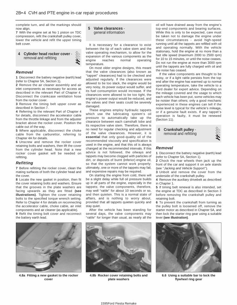
complete turn, and all the markings shouldnow align.7 With the engine set at No 1 piston on TDCcompression, refit the crankshaft pulley cover,lower the vehicle and refit the upper timingbelt cover.
4 Cylinder head rocker cover -removal and refitting 2
Removal1 Disconnect the battery negative (earth) lead(refer to Chapter 5A, Section 1).2 Remove the air cleaner assembly and airinlet components as necessary for access asdescribed in the relevant Part of Chapter 4.Disconnect the crankcase ventilation hosefrom the rocker cover.3 Remove the timing belt upper cover asdescribed in Section 7.4 Referring to the relevant Part of Chapter 4for details, disconnect the accelerator cablefrom the throttle linkage and from the adjusterbracket above the rocker cover. Position thecable out of the way.5 Where applicable, disconnect the chokecable from the carburettor, referring toChapter 4A for details.6 Unscrew and remove the rocker coverretaining bolts and washers, then lift the coverfrom the cylinder head. Note that a newrocker cover gasket will be needed onrefitting.
Refitting7 Before refitting the rocker cover, clean themating surfaces of both the cylinder head andthe cover.8 Locate the new gasket in position, then fitthe cover retaining bolts and washers. Ensurethat the grooves in the plate washers arefacing upwards as they are fitted (seeillustrations). Tighten the cover retainingbolts to the specified torque wrench setting.Refer to Chapter 4 for details on reconnectingthe accelerator cable, choke cable, air inletcomponents and air cleaner (as applicable).9 Refit the timing belt cover and reconnectthe battery earth lead.
5 Valve clearances - general information
It is necessary for a clearance to existbetween the tip of each valve stem and thevalve operating mechanism, to allow for theexpansion of the various components as theengine reaches normal operatingtemperature.
On most older engine designs, this meantthat the valve clearances (also known as“tappet” clearances) had to be checked andadjusted regularly. If the clearances wereallowed to be too slack, the engine would bevery noisy, its power output would suffer, andits fuel consumption would increase. If theclearances were allowed to be too tight, theengine’s power output would be reduced, andthe valves and their seats could be severelydamaged.
These engines employ hydraulic tappetswhich use the lubricating system’s oilpressure to automatically take up theclearance between each camshaft lobe andits respective valve stem. Therefore, there isno need for regular checking and adjustmentof the valve clearances. However, it isessential that only good-quality oil of therecommended viscosity and specification isused in the engine, and that this oil is alwayschanged at the recommended intervals. If thisadvice is not followed, the oilways andtappets may become clogged with particles ofdirt, or deposits of burnt (inferior) engine oil,so that the system cannot work properly;ultimately, one or more of the tappets may fail,and expensive repairs may be required.
On starting the engine from cold, there willbe a slight delay while full oil pressure buildsup in all parts of the engine, especially in thetappets; the valve components, therefore,may well “rattle” for about 10 seconds or so,and then quieten. This is a normal state ofaffairs, and is nothing to worry about,provided that all tappets quieten quickly andstay quiet.
After the vehicle has been standing forseveral days, the valve components may“rattle” for longer than usual, as nearly all the
oil will have drained away from the engine’stop-end components and bearing surfaces.While this is only to be expected, care mustbe taken not to damage the engine underthese circumstances - avoid high-speedrunning until all the tappets are refilled with oiland operating normally. With the vehiclestationary, hold the engine at no more than afast idle speed (maximum 2000 to 2500 rpm)for 10 to 15 minutes, or until the noise ceases.Do not run the engine at more than 3000 rpmuntil the tappets are fully charged with oil andthe noise has ceased.
If the valve components are thought to benoisy, or if a light rattle persists from the topend after the engine has warmed up to normaloperating temperature, take the vehicle to aFord dealer for expert advice. Depending onthe mileage covered and the usage to whicheach vehicle has been put, some vehicles maybe noisier than others; only a good mechanicexperienced in these engines can tell if thenoise level is typical for the vehicle’s mileage,or if a genuine fault exists. If any tappet’soperation is faulty, it must be renewed(Section 11).
6 Crankshaft pulley - removal and refitting 2
Removal1 Disconnect the battery negative (earth) lead(refer to Chapter 5A, Section 1).2 Chock the rear wheels then jack up thefront of the car and support it on axle stands(see “Jacking and Vehicle Support”).3 Unbolt and remove the cover from theunderside of the crankshaft pulley.4 Remove the auxiliary drivebelt as describedin Chapter 1.5 If timing belt renewal is also intended, setthe engine at TDC as described in Section 3before removing the crankshaft pulley andretaining bolt.6 To prevent the crankshaft from turning asthe pulley bolt is loosened off, remove thestarter motor as described in Chapter 5A, andthen lock the starter ring gear using a suitablelever (see illustration).
2B•4 CVH and PTE engine in-car repair procedures
6.6 Using a suitable bar to lock theflywheel ring gear
4.8b Rocker cover retaining bolts andplate washers
4.8a Fitting a new gasket to the rockercover
1595Ford Fiesta Remake

7 Unscrew and remove the crankshaft pulleyretaining bolt and its washer. Withdraw thepulley from the front end of the crankshaft(see illustration). If necessary, lever it freeusing a pair of diagonally-opposed leverspositioned behind the pulley.
Refitting8 Refit in the reverse order of removal. Tightenthe pulley retaining bolt to the specified torquesetting, and refer to Chapter 1 for details onrefitting the auxiliary drivebelt.9 On completion, reconnect the batterynegative lead.
7 Timing belt covers - removal and refitting 1
Removal1 Disconnect the battery negative (earth) lead(refer to Chapter 5A, Section 1).2 Where applicable, undo the two boltssecuring the power steering fluid pipe supportclips and ease the pipe away from the uppercover.3 Undo the two retaining bolts and removethe upper timing belt cover (see illustration).4 Refer to the previous Section for details,and remove the crankshaft pulley.5 Unscrew the two bolts securing the lowertiming belt cover, and remove it (seeillustration).
Refitting6 Refit in the reverse order of removal.Tighten the cover retaining bolts to thespecified torque wrench setting.7 On completion, reconnect the battery earthlead.
8 Timing belt - removal, refittingand adjustment 3
Removal1 Referring to the previous Sections fordetails, remove the rocker cover, thecrankshaft pulley and the timing belt covers.2 Check that the crankshaft is set with the No 1 piston at TDC (on its compressionstroke) before proceeding. If necessary, referto Section 3 for further details.3 To check the timing belt for correctadjustment, proceed as described inparagraph 12 below. To remove the belt,proceed as follows.4 Loosen off the two bolts securing the timingbelt tensioner. Using a large screwdriver, prisethe tensioner to one side to release the timingbelt tension. Secure the tensioner in thisposition by retightening the bolts (seeillustration).5 If the original timing belt is to be refitted,mark it for direction of travel and also theexact tooth engagement positions on all
sprockets. Slip the belt from the camshaft,water pump and crankshaft sprockets (seeillustration). Whilst the timing belt isremoved, avoid any excessive movement ofthe sprockets, otherwise the piston crownsand valves may come into contact and bedamaged.6 If the belt is being removed for reasonsother than routine renewal, check it carefullyfor any signs of uneven wear, splitting, cracks(especially at the roots of the belt teeth) orcontamination with oil or coolant. Renew thebelt if there is the slightest doubt about itscondition. As a safety measure, the belt mustbe renewed as a matter of course at theintervals given in Chapter 1; if its history isunknown, the belt should be renewedirrespective of its apparent conditionwhenever the engine is overhauled.
Refitting and adjustment7 Before refitting the belt, check that thecrankshaft is still at the TDC position, with thesmall projection on the belt sprocket frontflange aligned with the TDC mark on the oilpump housing (see illustration). Also ensurethat the camshaft sprocket is set with its TDCpointer aligned with the corresponding timingmark on the cylinder head (see illus-tration 3.6b). If necessary, adjust thesprockets slightly. As previously mentioned,avoid any excessive movement of thesprockets whilst the belt is removed.8 Engage the timing belt teeth with the teeth
CVH and PTE engine in-car repair procedures 2B•5
7.5 Lower timing belt cover removal7.3 Upper timing belt cover removal6.7 Crankshaft pulley removal
8.7 Sprocket and oil pump housing TDC marks in alignment
8.5 Timing belt removal8.4 Timing belt tensioner retaining bolts(arrowed)
2B
1595Ford Fiesta Remake

of the crankshaft sprocket, and then pull thebelt vertically upright on its right-hand run.Keep it taut, and engage it with the teeth ofthe camshaft sprocket. If the original belt isbeing refitted, check that the belt’s directionof travel is correct, and realign the belt-to-sprocket marks made during removal, toensure that the exact original engagementpositions are retained. When the belt is fullyfitted on the sprockets, check that thesprocket positions have not altered.9 Carefully manoeuvre the belt around thetensioner, and engage its teeth with the waterpump sprocket, again ensuring that the TDCpositions of the crankshaft and camshaft are not disturbed as the belt is finally located.10 Refit the lower timing belt cover, andtighten its retaining bolts to the specifiedtorque setting. Refit the crankshaft pulley, andtighten its retaining bolt to the specifiedtorque setting.11 To take up belt slack, loosen off thetensioner and move it towards the front of thecar to apply an initial tension to the belt.Secure the tensioner in this position, thenremove the flywheel ring gear locking device.12 Rotate the crankshaft through two fullrevolutions in (the normal direction of travel),returning to the TDC position (camshaftsprocket-to-cylinder head). Check that thecrankshaft pulley notch is aligned with theTDC (0) mark on the lower half of the timingbelt cover.13 Grasp the belt between the thumb andforefinger, at the midway point between thecrankshaft and camshaft sprockets on theright-hand side. If the belt tension is correct, itshould just be possible to twist the beltthrough 90º at this point (see illustration). Toadjust the belt, loosen off the tensionerretaining bolts, move the tensioner asrequired using a suitable screwdriver as alever, then retighten the retaining bolts. Rotatethe crankshaft to settle the belt, then recheck the tension. It may take two or threeattempts to get the tension correct. Oncompletion, tighten the tensioner bolts to thespecified torque wrench setting.14 It should be noted that this setting isapproximate, and the belt tension should berechecked by a Ford dealer with the special
tensioner-setting tool at the earliestopportunity.15 Refit the starter motor (refer to Chap-ter 5A).16 Refit the rocker cover (see Section 4) andthe upper timing belt cover (see Section 7).17 Refit the auxiliary drivebelt, adjust itstension as described in Chapter 1, then refitthe crankshaft pulley lower cover.18 On completion, reconnect the batteryearth lead.
9 Timing belt tensioner andsprockets - removal,inspection and refitting
3Tensioner1 Set the engine at TDC for No 1 piston oncompression as described in Section 3, thenrefer to Section 7 and remove the timing beltupper cover.2 Loosen off the two bolts securing the timingbelt tensioner. Using a large screwdriver, prisethe tensioner to one side to release the timingbelt tension.3 Remove the two tensioner bolts, andwithdraw the tensioner from behind the timingbelt.4 Check the condition of the tensioner,ensuring that it rotates smoothly on itsbearings, with no signs of roughness orexcessive free play. Renew the tensioner if indoubt about its condition.5 To refit the tensioner, first check that theengine is still positioned at TDC for No 1piston on compression, with both thecamshaft and crankshaft sprocket timingmarks correctly aligned as described inSection 3.6 Refit the tensioner, guiding it in positionaround the timing belt, and secure with thetwo bolts. Move the tensioner towards thefront of the car, to apply an initial tension tothe belt. Secure the tensioner in this position.7 Adjust the timing belt tension as describedin Section 8, paragraphs 12 to 14.8 Refit the timing belt upper cover oncompletion.
Camshaft sprocket9 Set the engine at TDC for No 1 piston oncompression as described in Section 3, thenrefer to Section 7 and remove the timing beltupper cover.10 Loosen off the two bolts securing thetiming belt tensioner. Using a largescrewdriver, prise the tensioner to one side torelease the timing belt tension. Slip the timingbelt off the camshaft sprocket.11 Pass a bar through one of the holes in thecamshaft sprocket to prevent the camshaftfrom rotating, then unscrew and remove thesprocket retaining bolt. Note that this boltmust be renewed when refitting the camshaftsprocket. Remove the sprocket, noting theWoodruff key fitted to the camshaft; if the keyis loose, remove it for safekeeping.12 Check the condition of the sprocket,inspecting carefully for any wear grooves,pitting or scoring around the teeth.13 Install the Woodruff key, then fit thecamshaft sprocket with a new retaining bolt.The threads of the bolt should be smearedwith thread-locking compound prior to fitting.Tighten the retaining bolt to the specifiedtorque wrench setting (see illustrations).14 Check that the engine is still positioned atTDC for No 1 piston on compression, withboth the camshaft and crankshaft sprockettiming marks correctly aligned as described inSection 3.15 Slip the timing belt over the camshaftsprocket, then move the tensioner towardsthe front of the car to apply an initial tension tothe belt. Secure the tensioner in this position.16 Adjust the timing belt tension asdescribed in Section 8, paragraphs 12 to 14.17 Refit the timing belt upper cover oncompletion.
Crankshaft sprocket18 Remove the timing belt as described inSection 8.19 The crankshaft sprocket can now bewithdrawn. If it is a tight fit on the crankshaft,a puller or two large screwdrivers can be usedto release its grip. Withdraw the thrustwasherand the Woodruff key from the crankshaft.20 Check the condition of the sprocket,
2B•6 CVH and PTE engine in-car repair procedures
9.13b . . . and tighten the retaining bolt tothe specified torque whilst retaining the
sprocket as shown
9.13a Refit the camshaft sprocket . . .
8.13 Checking the tension of the timingbelt
1595Ford Fiesta Remake

inspecting carefully for any wear grooves,pitting or scoring around the teeth.21 Refit the thrustwasher with its curved sidefacing outwards, followed by the Woodruffkey.22 Lubricate the oil seal and the crankshaftsprocket with engine oil, then position thesprocket on the crankshaft with its thrust facefacing outwards.23 Using the auxiliary drivebelt pulley and itsretaining bolt, draw the sprocket fully intoposition on the crankshaft. Remove thepulley.24 Refit the timing belt as described inSection 8.
10 Camshaft oil seal - renewal 31 Remove the camshaft sprocket asdescribed in the previous Section.2 The oil seal is now accessible for removal.Note its direction of fitting, then using asuitable screwdriver or a tool with a hookedend to lever and extract the seal from itshousing (but take care not to damage thehousing with the tool) (see illustration).3 Check that the housing is clean beforefitting the new seal. Lubricate the lips of theseal and the running faces of the camshaftwith clean engine oil. Carefully locate the sealover the camshaft, and drive it squarely intoposition using a suitable tube or a socket (seeillustration). An alternative method of fitting is
to draw it squarely into position using the oldsprocket bolt and a suitable distance piece.4 With the seal fully inserted in its housing,refit the camshaft sprocket as described inthe previous Section.
11 Camshaft, rocker arms andtappets - removal, inspectionand refitting
3Removal1 Disconnect the battery negative (earth) lead(refer to Chapter 5A, Section 1).2 Refer to the appropriate earlier Sections inthis Chapter, and remove the timing beltupper cover and the rocker cover.3 On carburettor models, refer to Chapter 4Aand remove the fuel pump. On models
equipped with a distributor ignition system,refer to Chapter 5B and remove the distributor.On PTE engines, refer to Chapter 4D andremove the camshaft position sensor.4 On models equipped with distributorlessignition system, detach, unbolt and removethe ignition coil, its support bracket and theinterference capacitor from the end of thecylinder head, as described in Chapter 5B.5 Undo the retaining nuts and remove theguides, rocker arms and spacer plates (seeillustrations). Keep the respectivecomponents in their original order of fitting bymarking them with a piece of numbered tape,or by using a suitable sub-divided box.6 Withdraw the hydraulic tappets, againkeeping them in their original fitted sequence.The tappets should be placed in an oil bathwhile removed (see illustrations).7 Unbolt and remove the lower cover beneath
CVH and PTE engine in-car repair procedures 2B•7
11.5a Undo the rocker arm retaining nut . . .
10.3 Using a socket to tap the camshaftoil seal into place
11.6b Store tappets in clearly-markedcontainer filled with oil to prevent oil loss
11.6a Removing a hydraulic tappet
11.5c . . . followed by the rocker arm . . .11.5b . . . withdraw the guide . . .
11.5d . . . and spacer plate
10.2 Camshaft front oil seal removal
2B
1595Ford Fiesta Remake

the crankshaft pulley, then with a spannerengaged on the crankshaft pulley bolt, turnthe crankshaft over to set the engine at TDCfor No 1 piston on compression (see Sec-tion 3).8 Remove the camshaft sprocket asdescribed in Section 9.9 Extract the camshaft oil seal as describedin Section 10.10 Before removing the camshaft and itsthrust plate, check and take note of theamount of camshaft endfloat, using a dialgauge or feeler gauges. With the camshaftendfloat measured and noted, unscrew thetwo retaining bolts and then extract thecamshaft thrust plate from its pocket at thefront end of the cylinder head (seeillustrations).11 On models with a distributorless ignition
system, at the rear end of the cylinder head,pierce the camshaft blanking plug with asuitable tool, and then lever it out of itsaperture (see illustrations).12 Withdraw the camshaft from the cylinderhead at the rear (distributor/ignition coil) end(see illustration). Take care not to damagethe bearings in the cylinder head as the shaftis withdrawn.
Inspection13 Clean and inspect the variouscomponents removed for signs of excessivewear.14 Examine the camshaft bearing journalsand lobes for damage or wear. If evident, anew camshaft will be required.15 Compare the previously-measuredcamshaft endfloat with that specified. If the
endfloat is outside of the specified tolerance,the thrust plate must be renewed.16 The camshaft bearing bore diameters inthe cylinder head should be measured andchecked against the tolerances specified. Asuitable measuring gauge will be required forthis, but if this is not available, check forexcessive movement between the camshaftjournals and the bearings. If the bearings arefound to be unacceptably worn, a newcylinder head is the only answer, as thebearings are machined directly into the head.17 It is seldom that the hydraulic tappets arebadly worn in the cylinder head bores butagain, if the bores are found to be wornbeyond an acceptable level, the cylinder headmust be renewed.18 If the contact surfaces of the cam lobesshow signs of depression or grooving, theycannot be renovated by grinding, as thehardened surface will be removed and theoverall length of the tappet(s) will be reduced.The self-adjustment point of the tappet will beexceeded as a result, so that the valveadjustment will be affected, resulting in noisyoperation. Therefore, renewal of the camshaftis the only remedy in this case.19 Inspect the rocker arm contact surfacesfor excessive wear, and renew if necessary(see illustration).
Refitting20 Refitting the camshaft and its associatedcomponents is a reversal of the removalprocedure, but note the following specialpoints.21 Lubricate the camshaft bearings, thecamshaft and the thrust plate with cleanengine oil prior to fitting them. As thecamshaft is inserted, take care not to damagethe bearings in the cylinder head. Tighten thecamshaft thrust plate retaining bolts to thespecified torque. When the thrust plate boltsare tightened, make a final check to ensurethat the camshaft endfloat is as specified.22 A new front oil seal must be fitted after thecamshaft has been installed (see previousSection for details). It will also be necessary toinsert a new blanking plug into the rear end ofthe cylinder head (where applicable). Drive itsquarely into position so that it is flush withthe head (see illustration).
2B•8 CVH and PTE engine in-car repair procedures
11.22 Driving a new blanking plug intoposition
11.19 Inspect the rocker arm contactpoints indicated for excessive wear
11.12 Withdraw the camshaft from thecylinder head
11.11b . . . and lever it out of the cylinderhead
11.11a Pierce the centre of the blankingplug . . .
11.10b . . . and lift out the camshaft thrustplate
11.10a Undo the two retaining bolts(arrowed) . . .
1595Ford Fiesta Remake

23 Refer to the procedure in Section 9 whenrefitting the camshaft sprocket.24 Refit and tension the timing belt asdescribed in Section 8.25 Lubricate the hydraulic tappets withhypoid oil before refitting them into theiroriginal locations in the cylinder head.26 Lubricate and refit the rocker arms andguides in their original sequence, use newnuts and tighten them to the specified torquesetting. It is essential, before each rocker armis installed and its nut tightened, that therespective cam follower is positioned at itslowest point (in contact with the cam basecircle). Turn the cam (using the crankshaftpulley bolt) as necessary to achieve this.27 Refit the rocker cover as described inSection 4.28 Refit the remaining components withreference to the relevant Sections in thisChapter or elsewhere in the manual.29 On completion, reconnect the batterynegative lead.
12 Cylinder head - removal and refitting 4
RemovalNote: The following procedure describesremoval and refitting of the cylinder headcomplete with inlet and exhaust manifolds. Ifwished, the manifolds may be removed first,as described in the relevant Part of Chapter 4,and the cylinder head then removed on itsown.1 On fuel-injected engines, depressurise thefuel system as described in Chapter 4B or 4C.2 Disconnect the battery negative (earth) lead(refer to Chapter 5A, Section 1).3 Refer to Chapter 1 and drain the coolingsystem.
4 Remove the rocker cover as described inSection 4.5 Disconnect the accelerator and chokecables as applicable (refer to the relevant Partof Chapter 4).6 Loosen off the retaining clips anddisconnect the upper coolant hose, theexpansion tank hose and the heater hosefrom the thermostat housing. Also disconnectthe heater hose from the inlet manifold.
7 On CFi models, disconnect the heatedcoolant hose from the injector unit.8 On EFi and SEFi models, disconnect thefollowing (see illustration):a) The MAP sensor vacuum hose from the
inlet manifold upper section (EFi models).b) The carbon canister solenoid valve
vacuum hose from the inlet manifoldupper section.
c) The oil trap vacuum hose at the “T” piececonnector.
d) The brake servo vacuum hose from theinlet manifold upper section by pressingin the clamp ring and simultaneouslypulling the hose free from the connection.
e) The coolant hose from the injectorintermediate flange and at the thermostathousing.
9 Disconnect the following fuel supply/returnhoses. Plug the hoses and connections, toprevent fuel spillage and the possible ingressof dirt.a) On carburettor models, disconnect the
fuel supply hose from the pump and thereturn hose from the carburettor.
b) On CFi models, pull free and detach thefuel return hose from the injection unitand the supply hose at the connector.
c) On EFi and SEFi models, detach the fuelsupply hose from the fuel rail or at thequick-release coupling (where fitted).Disconnect the return line from the fuelpressure regulator or at the quick-releasecoupling.
10 On CFi models, disconnect the brakeservo vacuum hose from the inlet manifold,the MAP sensor vacuum hose from thesensor, and the carbon canister connectinghose at the injection unit (see illustration).11 Noting their connections and routings,disconnect the wiring connectors or multi-plugs from the following items, whereapplicable:a) Temperature gauge sender unit.b) DIS ignition coil.c) Coolant temperature sensor.d) Cooling fan thermostatic switch.e) Carburettor.f) Radio earth lead.g) Road speed sensor.h) Fuel injector wiring loom.i) Intake air temperature sensor.12 On CFi models, detach the throttle controlmotor, throttle position sensor and injectorlead multi-plugs (see illustration).13 On models with a distributorless ignitionsystem, where still attached, disconnect theHT leads from the DIS ignition coil and thespark plugs. On models with a distributorignition system, remove the distributor asdescribed in Chapter 5B.14 Position the engine with No 1 piston atTDC on compression as described in Sec-tion 3.15 Loosen off the timing belt tensionerretaining bolts, and move the tensioner torelease the tension from the drivebelt.Support the belt, and move it clear of thecamshaft sprocket.16 Chock the rear wheels then jack up thefront of the car and support it on axle stands(see “Jacking and Vehicle Support”).17 Unscrew the retaining nuts and detachthe exhaust downpipe from the manifold.Remove the gasket; note that a new one must
CVH and PTE engine in-car repair procedures 2B•9
12.12 Wiring connections to be detachedon the 1.4 litre CFi fuel injected engine
A Coolant temperature sensorB Throttle plate control motorC Throttle position sensorD Injector
12.10 Vacuum hose to the MAP sensor (A)and the brake servo unit (B) on the 1.4 litre
CFi fuel-injected engine
12.8 Vacuum hoses and throttle cableconnections on the 1.6 litre EFi fuel
injected engine
A Hose to MAP sensorB Crankcase ventilation breather hoseC Throttle cable and clipD Oil trap hose and T-piece connectorE Hose to oil trapF Hose to carbon canister solenoid valve
2B
1595Ford Fiesta Remake
Whenever you disconnectany vacuum lines, coolant oremissions hoses, wiringconnectors and fuel lines,
always label them clearly, so that theycan be correctly reassembled. Maskingtape and/or a touch-up paint applicatorwork well for marking items. Takeinstant photos, or sketch the locationsof components and brackets.
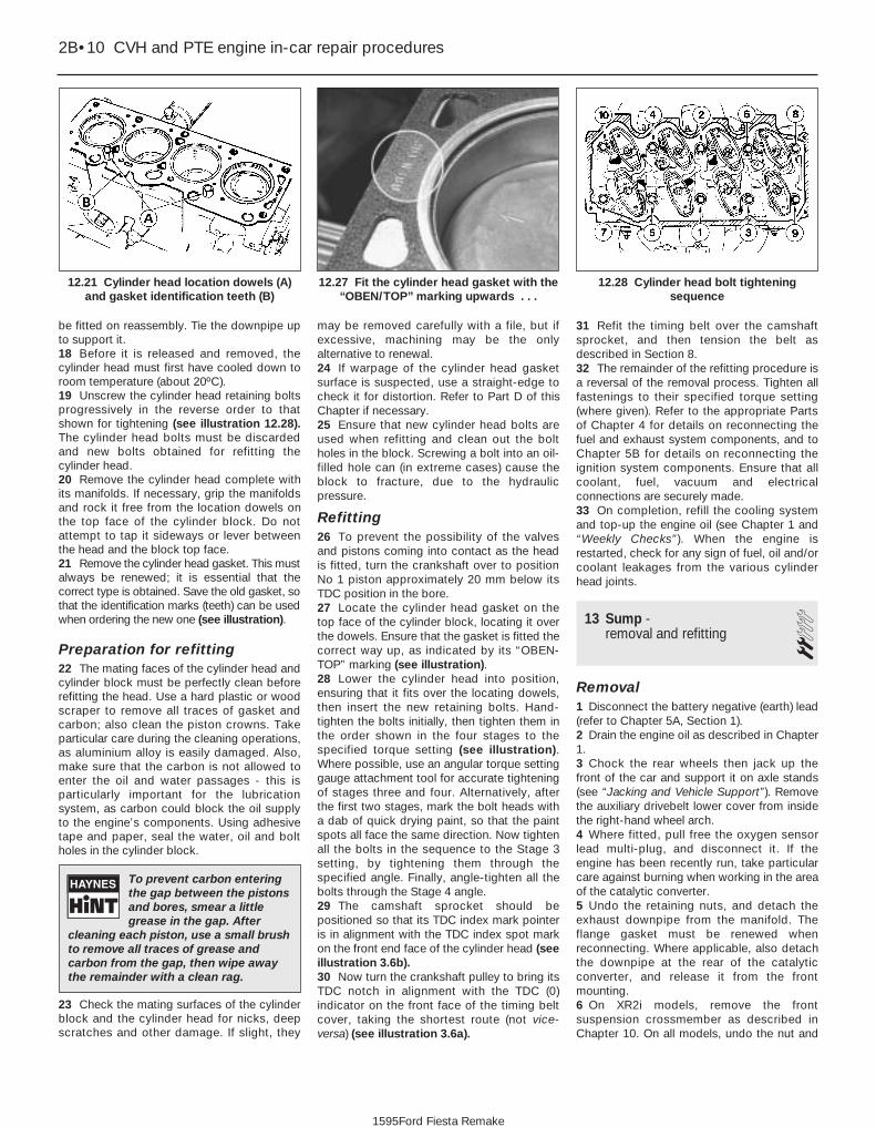
be fitted on reassembly. Tie the downpipe upto support it.18 Before it is released and removed, thecylinder head must first have cooled down toroom temperature (about 20ºC).19 Unscrew the cylinder head retaining boltsprogressively in the reverse order to thatshown for tightening (see illustration 12.28).The cylinder head bolts must be discardedand new bolts obtained for refitting thecylinder head.20 Remove the cylinder head complete withits manifolds. If necessary, grip the manifoldsand rock it free from the location dowels onthe top face of the cylinder block. Do notattempt to tap it sideways or lever betweenthe head and the block top face.21 Remove the cylinder head gasket. This mustalways be renewed; it is essential that thecorrect type is obtained. Save the old gasket, sothat the identification marks (teeth) can be usedwhen ordering the new one (see illustration).
Preparation for refitting22 The mating faces of the cylinder head andcylinder block must be perfectly clean beforerefitting the head. Use a hard plastic or woodscraper to remove all traces of gasket andcarbon; also clean the piston crowns. Takeparticular care during the cleaning operations,as aluminium alloy is easily damaged. Also,make sure that the carbon is not allowed toenter the oil and water passages - this isparticularly important for the lubricationsystem, as carbon could block the oil supplyto the engine’s components. Using adhesivetape and paper, seal the water, oil and boltholes in the cylinder block.
23 Check the mating surfaces of the cylinderblock and the cylinder head for nicks, deepscratches and other damage. If slight, they
may be removed carefully with a file, but ifexcessive, machining may be the onlyalternative to renewal.24 If warpage of the cylinder head gasketsurface is suspected, use a straight-edge tocheck it for distortion. Refer to Part D of thisChapter if necessary.25 Ensure that new cylinder head bolts areused when refitting and clean out the boltholes in the block. Screwing a bolt into an oil-filled hole can (in extreme cases) cause theblock to fracture, due to the hydraulicpressure.
Refitting26 To prevent the possibility of the valvesand pistons coming into contact as the headis fitted, turn the crankshaft over to positionNo 1 piston approximately 20 mm below itsTDC position in the bore.27 Locate the cylinder head gasket on thetop face of the cylinder block, locating it overthe dowels. Ensure that the gasket is fitted thecorrect way up, as indicated by its “OBEN-TOP” marking (see illustration).28 Lower the cylinder head into position,ensuring that it fits over the locating dowels,then insert the new retaining bolts. Hand-tighten the bolts initially, then tighten them inthe order shown in the four stages to thespecified torque setting (see illustration).Where possible, use an angular torque settinggauge attachment tool for accurate tighteningof stages three and four. Alternatively, afterthe first two stages, mark the bolt heads witha dab of quick drying paint, so that the paintspots all face the same direction. Now tightenall the bolts in the sequence to the Stage 3setting, by tightening them through thespecified angle. Finally, angle-tighten all thebolts through the Stage 4 angle.29 The camshaft sprocket should bepositioned so that its TDC index mark pointeris in alignment with the TDC index spot markon the front end face of the cylinder head (seeillustration 3.6b).30 Now turn the crankshaft pulley to bring itsTDC notch in alignment with the TDC (0)indicator on the front face of the timing beltcover, taking the shortest route (not vice-versa) (see illustration 3.6a).
31 Refit the timing belt over the camshaftsprocket, and then tension the belt asdescribed in Section 8.32 The remainder of the refitting procedure isa reversal of the removal process. Tighten allfastenings to their specified torque setting(where given). Refer to the appropriate Partsof Chapter 4 for details on reconnecting thefuel and exhaust system components, and toChapter 5B for details on reconnecting theignition system components. Ensure that allcoolant, fuel, vacuum and electricalconnections are securely made.33 On completion, refill the cooling systemand top-up the engine oil (see Chapter 1 and“Weekly Checks”). When the engine isrestarted, check for any sign of fuel, oil and/orcoolant leakages from the various cylinderhead joints.
13 Sump - removal and refitting 2
Removal1 Disconnect the battery negative (earth) lead(refer to Chapter 5A, Section 1).2 Drain the engine oil as described in Chapter1.3 Chock the rear wheels then jack up thefront of the car and support it on axle stands(see “Jacking and Vehicle Support”). Removethe auxiliary drivebelt lower cover from insidethe right-hand wheel arch.4 Where fitted, pull free the oxygen sensorlead multi-plug, and disconnect it. If theengine has been recently run, take particularcare against burning when working in the areaof the catalytic converter.5 Undo the retaining nuts, and detach theexhaust downpipe from the manifold. Theflange gasket must be renewed whenreconnecting. Where applicable, also detachthe downpipe at the rear of the catalyticconverter, and release it from the frontmounting.6 On XR2i models, remove the frontsuspension crossmember as described inChapter 10. On all models, undo the nut and
2B•10 CVH and PTE engine in-car repair procedures
12.28 Cylinder head bolt tighteningsequence
12.27 Fit the cylinder head gasket with the“OBEN/TOP” marking upwards . . .
12.21 Cylinder head location dowels (A)and gasket identification teeth (B)
1595Ford Fiesta Remake
To prevent carbon enteringthe gap between the pistonsand bores, smear a littlegrease in the gap. After
cleaning each piston, use a small brushto remove all traces of grease andcarbon from the gap, then wipe awaythe remainder with a clean rag.

bolt(s) securing the gearchange mechanismstabiliser bar/exhaust forward mountingbracket (where fitted) and ease it out of theway.7 Remove the starter motor as described inChapter 5A, then undo the retaining bolts, andremove the clutch cover plate from the frontface of the bellhousing (see illustration).8 Progressively unscrew the sump retainingbolts and remove them. Support and lowerthe sump pan, taking care not to spill any oilremaining in it as it is removed. If the sump isstuck to the base of the crankcase, prise itfree using a screwdriver, but take care not todamage the sump flange face. If it is reallystuck in position, check first that all of thebolts are removed, then cut around the sumpgasket with a sharp knife to help in freeing thejoint.9 After the sump is removed, further oil willalmost certainly continue to drip down fromwithin the crankcase, some old newspaperspositioned underneath will soak up thespillage whilst the sump is removed.10 Clean the sump of old oil and sludge,using paraffin or a suitable engine cleanersolution. Clean any traces of old gasket andsealer from the mating faces of the sump andthe crankcase.
Refitting11 Smear a suitable sealing compound ontothe junctions of the crankcase-to-oil seal
carrier at the rear and the crankcase-to-oilpump housing at the front on each side (seeillustration).12 Insert a new rubber seal in the groove inthe rear oil seal carrier and the oil pump case.As an aid to correct sump alignment whenrefitting it, screw ten M6 studs into thecylinder block, in the positions circled inillustration 13.14.13 Fit a new gasket over the studs. Fit thesump into position, ensuring that the raisedspacers sit in the gasket. Insert the bolts intothe available holes, and finger-tighten themonly at this stage. Now remove the studs andfit the remaining bolts, again finger-tight.14 Tighten the sump bolts in a progressive,numerical sequence to the specified torquewrench setting (see illustration).15 Fit the sump drain plug with a new sealingwasher, and tighten it to the specified torquewrench setting.16 Refit the clutch cover plate, the auxiliarydrivebelt lower cover, the front suspensioncrossmember, the gearchange mechanismstabiliser bar/exhaust forward mountingbracket, and the starter motor with referenceto the relevant Sections and Chapters of thismanual as applicable.17 Reconnect the exhaust downpipe asdescribed in Chapter 4E.18 On completion, lower the vehicle, and fillthe engine with oil as described in Chapter 1.Reconnect the battery negative lead.
14 Oil pump - removal and refitting 3
Removal1 Disconnect the battery negative (earth) lead(refer to Chapter 5A, Section 1).2 Remove the auxiliary drivebelt (see Chap-ter 1).3 Remove the crankshaft pulley (Section 6),the timing belt covers (Section 7), the timingbelt, crankshaft sprocket and thrustwasher(Sections 8 and 9), and the sump (Section 13).4 Unscrew the retaining nut/bolts and removethe oil pick-up pipe (see illustration).5 Unbolt and withdraw the oil pump from thefront face of the engine. Clean the oil pumpfor inspection. Refer to Section 15 for theinspection procedures. The oil seal in the oilpump housing should always be renewed(Section 16).
Refitting6 Before refitting the oil pump and theassociated fittings, clean off the respectivemating faces. A new oil pump gasket must beobtained, as well as the seals and gaskets forthe other associated components to berefitted.7 When refitting the oil pump, precautionarymeasures must be taken to avoid thepossibility of damaging the new oil seal as it isengaged over the shoulder and onto its journalon the crankshaft. Extract the Woodruff keyfrom the groove in the crankshaft, then cut athin plastic guide which will furl over andprotrude beyond the shoulder of the sealjournal on the crankshaft (see illus-tration 14.9b). This will allow the seal to rideover the step, and avoid damaging the seal lipas it is pushed into position on the crankshaft.8 If a new oil pump is being fitted or the oldpump is to be re-used after cleaning andinspection, first prime the pump by squirtingclean engine oil into it, and simultaneouslyrotating the drivegear a few times (seeillustration).
CVH and PTE engine in-car repair procedures 2B•11
13.14 Sump bolt tightening sequence
A Crankshaft pulley end of engineCircled numbers indicate locations of studsfor correct sump alignment (see text)
13.11 Sealing compound applicationpoints prior to refitting the sump
A Crankcase-to-oil pump housingB Crankcase-to-rear oil seal carrier
13.7 Removing the clutch cover plate
14.8 Prime the oil pump prior to fitting14.4 Removing the oil inlet pipe
2B
1595Ford Fiesta Remake

9 Align the pump gear flats with those on thecrankshaft, then fit the oil pump. Check thatthe sump mating faces of the oil pump andthe base of the crankcase are flush each side,then tighten the retaining bolts to thespecified torque setting. Remove theprotective guide (see illustrations).10 Refit the oil pick-up tube to the oil pump,using a new gasket and tighten to thespecified torque.11 Slide the thrustwasher onto the front endof the crankshaft, then insert the Woodruff keyinto position in the groove in the crankshaft.The key must be located with its flat edgeparallel with the line of the crankshaft, toensure that the crankshaft sprocket slidesfully into position as it is being refitted.12 Refit the sump, crankshaft sprocket, thetiming belt, timing belt cover and drivebeltpulley (as described in the appropriate earlierSections of this Chapter). Refit and adjust thedrivebelt as described in Chapter 1.13 On completion, lower the vehicle andreconnect the battery negative terminal.
15 Oil pump - dismantling,inspection and reassembly 3
Dismantling1 The oil pump fitted is a low-friction rotor-type, driven from the front end of thecrankshaft. Where a high-mileage engine is
being reconditioned, it is recommended that anew oil pump is fitted.2 To inspect the rotor assembly, first removethe pump from the engine (Section 14), thenundo the retaining screws and remove thecover plate (see illustration). Remove the O-ring seal.
Inspection3 Clean the rotors and the inside of the pumphousing, then visually inspect the variouscomponents for signs of excessive wear andscoring. Check the pump components forwear using feeler gauges in the same manneras that described in Part A of this Chapter,Section 13. Refer to the Specifications at thestart of this Chapter for specific details.
Reassembly4 When reassembling the pump, ensure thatthe inner (driving) and outer (driven) rotors arelocated with the corresponding indentedmatchmarks facing the same way (seeillustration).
16 Crankshaft oil seals -renewal 4
Front oil seal1 Disconnect the battery negative (earth) lead(refer to Chapter 5A, Section 1).2 Chock the rear wheels then jack up the
front of the car and support it on axle stands(see “Jacking and Vehicle Support”).3 Remove the auxiliary drivebelt as describedin Chapter 1.4 Remove the crankshaft pulley (Section 6),the timing belt covers (Section 7), the timingbelt (Section 8) and crankshaft sprocket,Woodruff key and thrustwasher (Section 9).5 The oil seal is now accessible for removalfrom the front face of the oil pump housing(see illustration). To withdraw the seal, ahooked tool will be required; if available, useFord special tool No 21-096. Take care not todamage the oil pump housing during removal.As it is removed, note the fitted orientation ofthe seal in its housing.6 Clean the oil pump housing and thecrankshaft stub, then lubricate the lips of thenew seal and the crankshaft front stub withclean engine oil.7 The oil seal should be drawn into positionusing the Ford special tool No 21-093A.Failing this, use a tube of suitable diameter,with the crankshaft pulley bolt and washers.Do not hammer the seal into position. Toprotect the seal lips as it is fitted onto thecrankshaft, cut a thin sheet of plastic to suitand furl it round the front of the crankshaft,over the journal shoulder.8 When the seal is fully fitted, remove thespecial tool (or fabricated tool) and withdrawthe plastic protector. Check that thecrankshaft is still at the TDC position and refitthe Woodruff key, thrustwasher and sprocket.Refit and tension the timing belt, then refit thetiming belt cover and crankshaft pulley asdescribed in the appropriate Sections earlierin this Chapter.9 Refit and adjust the auxiliary drivebelt asdescribed in Chapter 1.10 On completion, lower the vehicle andreconnect the battery.
Rear oil seal11 With the engine or transmission removedfrom the vehicle for access, remove the clutchas described in Chapter 6.12 Remove the flywheel/driveplate asdescribed in Section 18.13 If available, use Ford tool No 21-151 or asuitable clawed tool to extract the seal from
2B•12 CVH and PTE engine in-car repair procedures
16.5 Crankshaft front oil seal - seen frombelow (arrowed)
15.4 Inner and outer rotor matchmarks(arrowed)
15.2 Oil pump cover plate retainingscrews (arrowed)
14.9b With the oil pump refitted, removethe protective guide (arrowed)
14.9a Refit the oil pump
1595Ford Fiesta Remake

its housing. If the seal housing is removedfrom the rear face of the engine, the seal canbe removed as described in paragraph 18. Asit is removed, note the direction of fitting, andtake care not to damage the seal housing asthe seal is extracted.14 Clean the seal housing, the crankshaftrear flange face, and the flywheel/driveplatemating surfaces.15 One of two possible methods may beused to insert the new oil seal, depending onthe tools available.16 If Ford special service tool No 21-095 isavailable, lubricate the seal lips of the seal andits running face on the crankshaft with cleanengine oil. Position the seal (correctlyorientated) into the special tool, then draw theseal into the housing using twoflywheel/driveplate securing bolts so that theseal is against the stop.17 If the correct Ford service tool is notavailable, it will be necessary to remove the oilseal carrier housing. To do this, first removethe sump as described in Section 13, thenunscrew the seal housing retaining bolts andremove the housing from the rear face of thecrankcase.18 Drive the old seal from the housing bycarefully tapping it from its aperture using asuitable punch as shown (see illustration). Asit is removed, note the direction of fitting, andtake care not to damage the seal housing asthe seal is extracted.19 New gaskets will be required for the sealhousing and sump during reassembly. Cleanthe mating faces of the seal housing, thecrankcase and sump. Insert the new sealsquarely into its housing. To avoid damagingthe seal or the housing, place a flat piece ofwood across the face of the seal, andcarefully tap or draw the seal into place. Donot allow the seal to tilt in the housing as it isbeing fitted.20 Lubricate the running surface on thecrankshaft and the oil seal lip with cleanengine oil. Locate a new gasket onto the rearface of the crankcase, and refit the oil sealhousing and seal. To avoid damaging the lipsof the seal as it is passed over the end of thecrankshaft, cut a thin sheet of plastic to suitand furl it round the rear flange of the
crankshaft so that it protrudes, and press theseal over it. With the seal in position, withdrawthe plastic protector. Centralise the seal on theshaft, check that the housing-to-sump flangefaces are flush to the sump face on the base ofthe crankcase, then insert and tighten thehousing retaining bolts to the specified torque.21 Refit the sump with reference to Sec-tion 13.22 Refit the flywheel/driveplate as describedin Section 18.23 Refit the clutch as described in Chapter 6.24 Refit the engine or transmission, asapplicable.
17 Engine/transmissionmountings - renewal 2
1 The removal and refitting method for thetransmission bearer and mountings is asdescribed for HCS engines in Part A, Sec-tion 15. On XR2i models, it will be necessaryto remove the front suspension crossmemberfirst (refer to Chapter 10).
2 The engine right-hand mounting issignificantly different to that fitted to HCSengines, in that it is a two-piece bracket, andits removal and refitting procedure is detailedbelow.3 First of all support the engine/transmissionassembly as described in Part A, Section 15,then unscrew and remove the two nutssecuring the two halves of the mountingbracket assembly.4 Unscrew and remove the three boltssecuring the engine bracket section to thecylinder block (see illustration).5 Unscrew and remove the mountingretaining nut and washer from their locationnear the suspension strut.6 Unscrew and remove the mounting sidebolt from under the right-hand wheel arch.7 Refitting is a reversal of the removalprocedure. Make sure when refittingengine/transmission mountings, that anywashers and plates removed during thedismantling process are refitted in theiroriginal sequence. Do not fully tighten anymounting bolts until they are all located. Asthe mounting bolts and nuts are tightened,check that the mounting rubbers do not twist.
CVH and PTE engine in-car repair procedures 2B•13
17.4 Exploded view of the right-hand engine mounting16.18 Rear oil seal removal
2B
1595Ford Fiesta Remake

18 Flywheel/driveplate -removal, inspection andrefitting
3Removal1 Access to the flywheel (manual transmission)or driveplate (automatic transmission) is gainedby first removing the transmission (Chapter 7Aor B). On manual transmission models, removethe clutch (Chapter 6).2 Unscrew and remove the sixflywheel/driveplate retaining bolts, andcarefully withdraw the flywheel/driveplate
from the rear face of the crankshaft. Take carenot to drop the flywheel, as it is heavy. Notethat the retaining bolts must be renewed whenrefitting.
Inspection3 The inspection procedures for theflywheel/driveplate are the same as thosedescribed for the HCS engine in Part A of thisChapter, but note that the grinding proceduresdo not apply to automatic transmissionmodels (the driveplate cannot be reground).
Refitting4 Check that the mating faces of the
flywheel/driveplate and crankshaft are cleanbefore refitting.5 Smear the new retaining bolt threads withthread-locking compound. Fit theflywheel/driveplate into position on the rear endface of the crankshaft. Check that all of the boltholes in the flywheel/driveplate are in exactalignment with the corresponding bolt holes inthe crankshaft, then insert the new bolts andtighten them in a progressive sequence to thespecified torque wrench setting.6 Refit the clutch (manual transmissionmodels) as described in Chapter 6.7 Refit the transmission (according to type) asdescribed in Chapter 7A or B.
2B•14 CVH and PTE engine in-car repair procedures
1595Ford Fiesta Remake

2C
1595Ford Fiesta Remake
GeneralEngine type . . . . . . . . . . . . . . . . . . . . . . . . . . . . . . . . . . . . . . . . . . . . . . . Four-cylinder, in-line, double overhead camshaftsEngine code:
1.6 litre models . . . . . . . . . . . . . . . . . . . . . . . . . . . . . . . . . . . . . . . . . . L1G1.8 litre models . . . . . . . . . . . . . . . . . . . . . . . . . . . . . . . . . . . . . . . . . . RDB or RQC
Capacity:1.6 litre models . . . . . . . . . . . . . . . . . . . . . . . . . . . . . . . . . . . . . . . . . . 1597 cc1.8 litre models . . . . . . . . . . . . . . . . . . . . . . . . . . . . . . . . . . . . . . . . . . 1796 cc
Bore:1.6 litre models . . . . . . . . . . . . . . . . . . . . . . . . . . . . . . . . . . . . . . . . . . 76.0 mm1.8 litre models . . . . . . . . . . . . . . . . . . . . . . . . . . . . . . . . . . . . . . . . . . 80.6 mm
Stroke - all models . . . . . . . . . . . . . . . . . . . . . . . . . . . . . . . . . . . . . . . . . 88.0 mmCompression ratio:
1.6 litre models . . . . . . . . . . . . . . . . . . . . . . . . . . . . . . . . . . . . . . . . . . 10.3:11.8 litre models . . . . . . . . . . . . . . . . . . . . . . . . . . . . . . . . . . . . . . . . . . 10.0:1
Firing order . . . . . . . . . . . . . . . . . . . . . . . . . . . . . . . . . . . . . . . . . . . . . . . 1-3-4-2 (No 1 cylinder at timing belt end)Direction of crankshaft rotation . . . . . . . . . . . . . . . . . . . . . . . . . . . . . . . Clockwise (seen from right-hand side of vehicle)
Cylinder headHydraulic tappet bore inside diameter . . . . . . . . . . . . . . . . . . . . . . . . . . 28.395 to 28.425 mm
Camshafts and hydraulic tappetsCamshaft bearing journal diameter . . . . . . . . . . . . . . . . . . . . . . . . . . . . 25.960 to 25.980 mmCamshaft bearing journal-to-cylinder head running clearance . . . . . . . 0.020 to 0.070 mmCamshaft endfloat . . . . . . . . . . . . . . . . . . . . . . . . . . . . . . . . . . . . . . . . . 0.080 to 0.220 mm
LubricationEngine oil type/specification . . . . . . . . . . . . . . . . . . . . . . . . . . . . . . . . . . See “Lubricants, fluids and tyre pressures”Engine oil capacity . . . . . . . . . . . . . . . . . . . . . . . . . . . . . . . . . . . . . . . . . See “Lubricants, fluids and tyre pressures”Oil pressure:
Idling . . . . . . . . . . . . . . . . . . . . . . . . . . . . . . . . . . . . . . . . . . . . . . . . . . 1.3 to 2.5 barAt 4000 rpm . . . . . . . . . . . . . . . . . . . . . . . . . . . . . . . . . . . . . . . . . . . . 3.7 to 5.5 bars
Oil pump clearances . . . . . . . . . . . . . . . . . . . . . . . . . . . . . . . . . . . . . . . . Not specified
Chapter 2 Part C:Zetec engine in-car repair procedures
Auxiliary drivebelt check and renewal . . . . . . . . . . . . . . .See Chapter 1Camshaft oil seals - renewal . . . . . . . . . . . . . . . . . . . . . . . . . . . . . . . 10Camshafts and hydraulic tappets - removal, inspection
and refitting . . . . . . . . . . . . . . . . . . . . . . . . . . . . . . . . . . . . . . . . . . 11Compression test - description and interpretation . . . . . . . . . . . . . . 2Crankshaft oil seals - renewal . . . . . . . . . . . . . . . . . . . . . . . . . . . . . . 15Crankshaft pulley - removal and refitting . . . . . . . . . . . . . . . . . . . . . 6Cylinder head - removal and refitting . . . . . . . . . . . . . . . . . . . . . . . . 12Cylinder head cover - removal and refitting . . . . . . . . . . . . . . . . . . . 4Engine oil and filter renewal . . . . . . . . . . . . . . . . . . . . . . .See Chapter 1Engine oil level check . . . . . . . . . . . . . . . . . . . . . . . . .“Weekly Checks”
Engine/transmission mountings - inspection and renewal . . . . . . . . 16Flywheel/driveplate - removal, inspection and refitting . . . . . . . . . . 17General information . . . . . . . . . . . . . . . . . . . . . . . . . . . . . . . . . . . . . . 1Oil pump - removal, inspection and refitting . . . . . . . . . . . . . . . . . . . 14Sump - removal and refitting . . . . . . . . . . . . . . . . . . . . . . . . . . . . . . . 13Timing belt - removal, refitting and adjustment . . . . . . . . . . . . . . . . 8Timing belt covers - removal and refitting . . . . . . . . . . . . . . . . . . . . . 7Timing belt tensioner and sprockets - removal, inspection
and refitting . . . . . . . . . . . . . . . . . . . . . . . . . . . . . . . . . . . . . . . . . . 9Top Dead Centre (TDC) for No 1 piston - locating . . . . . . . . . . . . . . 3Valve clearances - general information . . . . . . . . . . . . . . . . . . . . . . . 5
2C•1
Specifications
Contents
Easy, suitable fornovice with littleexperience
Fairly easy, suitablefor beginner withsome experience
Fairly difficult,suitable for competentDIY mechanic
Difficult, suitable forexperienced DIYmechanic
Very difficult,suitable for expert DIYor professional
Degrees of difficulty
54321

Torque wrench settings Nm lbf ftCylinder head cover bolts:
Stage 1 . . . . . . . . . . . . . . . . . . . . . . . . . . . . . . . . . . . . . . . . . . . . . . . . 2 1.5Stage 2 . . . . . . . . . . . . . . . . . . . . . . . . . . . . . . . . . . . . . . . . . . . . . . . . 7 5
Camshaft sprocket bolts . . . . . . . . . . . . . . . . . . . . . . . . . . . . . . . . . . . . 68 50Camshaft bearing cap bolts:
Stage 1 . . . . . . . . . . . . . . . . . . . . . . . . . . . . . . . . . . . . . . . . . . . . . . . . 9 7Stage 2 . . . . . . . . . . . . . . . . . . . . . . . . . . . . . . . . . . . . . . . . . . . . . . . . 19 14
Cylinder head bolts:Stage 1 . . . . . . . . . . . . . . . . . . . . . . . . . . . . . . . . . . . . . . . . . . . . . . . . 24 18Stage 2 . . . . . . . . . . . . . . . . . . . . . . . . . . . . . . . . . . . . . . . . . . . . . . . . 45 33Stage 3 . . . . . . . . . . . . . . . . . . . . . . . . . . . . . . . . . . . . . . . . . . . . . . . . Angle-tighten a further 105º
Timing belt cover fasteners:Upper-to-middle (outer) cover bolts . . . . . . . . . . . . . . . . . . . . . . . . . . 4 3Cover-to-cylinder head or block bolts . . . . . . . . . . . . . . . . . . . . . . . . 7 5Cover studs-to-cylinder head or block . . . . . . . . . . . . . . . . . . . . . . . . 9 7
Timing belt tensioner bolt . . . . . . . . . . . . . . . . . . . . . . . . . . . . . . . . . . . . 38 28Timing belt tensioner backplate locating peg . . . . . . . . . . . . . . . . . . . . . 9 7Timing belt tensioner spring retaining pin . . . . . . . . . . . . . . . . . . . . . . . 9 7Timing belt guide pulley bolts . . . . . . . . . . . . . . . . . . . . . . . . . . . . . . . . . 38 28Water pump pulley bolts . . . . . . . . . . . . . . . . . . . . . . . . . . . . . . . . . . . . . 9 7Auxiliary drivebelt idler pulley . . . . . . . . . . . . . . . . . . . . . . . . . . . . . . . . . 47 35Front engine lifting eye bolt . . . . . . . . . . . . . . . . . . . . . . . . . . . . . . . . . . 16 12Exhaust manifold heat shield bolts:
Shield-to-cylinder head . . . . . . . . . . . . . . . . . . . . . . . . . . . . . . . . . . . 7 5Shield/dipstick tube . . . . . . . . . . . . . . . . . . . . . . . . . . . . . . . . . . . . . . 9 7Shield/coolant pipe-to-manifold . . . . . . . . . . . . . . . . . . . . . . . . . . . . . 23 17
Crankshaft pulley bolt . . . . . . . . . . . . . . . . . . . . . . . . . . . . . . . . . . . . . . . 115 85Oil pump-to-cylinder block bolts . . . . . . . . . . . . . . . . . . . . . . . . . . . . . . 10 7Oil pick-up pipe-to-pump screws . . . . . . . . . . . . . . . . . . . . . . . . . . . . . . 10 7Oil baffle/pump pick-up pipe nuts . . . . . . . . . . . . . . . . . . . . . . . . . . . . . 19 14Oil filter adapter-to-pump . . . . . . . . . . . . . . . . . . . . . . . . . . . . . . . . . . . . 22 16Oil pressure warning light switch . . . . . . . . . . . . . . . . . . . . . . . . . . . . . . 27 20Sump bolts . . . . . . . . . . . . . . . . . . . . . . . . . . . . . . . . . . . . . . . . . . . . . . . 20 15Coolant pipe-to-sump bolt . . . . . . . . . . . . . . . . . . . . . . . . . . . . . . . . . . . 9 7Flywheel/driveplate bolts . . . . . . . . . . . . . . . . . . . . . . . . . . . . . . . . . . . . 110 81Crankshaft left-hand oil seal carrier bolts . . . . . . . . . . . . . . . . . . . . . . . . 22 16Engine mountings:
Engine front right-hand mounting:Alternator mounting bracket-to-cylinder block bolts . . . . . . . . . . . 41 to 58 30 to 43Mounting bracket-to-alternator mounting bracket bolts . . . . . . . . Not available Not availableMounting through-bolt . . . . . . . . . . . . . . . . . . . . . . . . . . . . . . . . . . Not available Not availableOuter bracket-to-mounting bolts . . . . . . . . . . . . . . . . . . . . . . . . . . 58 to 79 43 to 58Inner bracket-to-body bolts . . . . . . . . . . . . . . . . . . . . . . . . . . . . . . 58 to 79 43 to 58Outer bracket-to-body bolts . . . . . . . . . . . . . . . . . . . . . . . . . . . . . . 58 to 79 43 to 58
Engine rear right-hand mounting: . . . . . . . . . . . . . . . . . . . . . . . . . . . .Bracket-to-cylinder block bolts . . . . . . . . . . . . . . . . . . . . . . . . . . . 76 to 104 56 to 77Mounting-to-(cylinder block) bracket bolts . . . . . . . . . . . . . . . . . . . 71 to 98 52 to 72Mounting-to-body bolt and nut . . . . . . . . . . . . . . . . . . . . . . . . . . . . 102 to 138 75 to 102
Transmission mounting fasteners . . . . . . . . . . . . . . . . . . . . . . . . . . . . Refer to Chapter 7A or 7BNote: Refer to Part D of this Chapter for remaining torque wrench settings.
2C•2 Zetec engine in-car repair procedures
1595Ford Fiesta Remake
1 General information
How to use this ChapterThis Part of Chapter 2 is devoted to repair
procedures possible while the engine is stillinstalled in the vehicle, and includes only theSpecifications relevant to those procedures.Similar information concerning the 1.3 litreHCS engines, and the 1.4 and 1.6 litre CVHand PTE engines, will be found in Parts A and B of this Chapter respectively. Since
these procedures are based on theassumption that the engine is installed in thevehicle, if the engine has been removed fromthe vehicle and mounted on a stand, some of the preliminary dismantling steps outlinedwill not apply.
Information concerning engine/transmissionremoval and refitting, and engine overhaul, canbe found in Part D of this Chapter, which alsoincludes the Specifications relevant to thoseprocedures.
Engine descriptionThe Zetec engine, (formerly Zeta), is of
sixteen-valve, double overhead camshaft
(DOHC), four-cylinder, in-line type, mountedtransversely at the front of the vehicle, withthe transmission on its left-hand end.
Apart from the plastic timing belt coversand the cast-iron cylinder block/crankcase, allmajor engine castings are of aluminium alloy.
The crankshaft runs in five main bearings,the centre main bearing’s upper halfincorporating thrustwashers to controlcrankshaft endfloat. The connecting rodsrotate on horizontally-split bearing shells attheir big-ends. The pistons are attached to theconnecting rods by gudgeon pins which arean interference fit in the connecting rod small-end eyes. The aluminium alloy pistons are

fitted with three piston rings: twocompression rings and an oil control ring.After manufacture, the cylinder bores andpiston skirts are measured and classified intothree grades, which must be carefullymatched together, to ensure the correctpiston/cylinder clearance; no oversizes areavailable to permit reboring.
The inlet and exhaust valves are eachclosed by coil springs; they operate in guideswhich are shrink-fitted into the cylinder head,as are the valve seat inserts.
Both camshafts are driven by the sametoothed timing belt, each operating eightvalves via self-adjusting hydraulic tappets,thus eliminating the need for routine checkingand adjustment of the valve clearances. Eachcamshaft rotates in five bearings that are line-bored directly in the cylinder head and the(bolted-on) bearing caps; this means that thebearing caps are not available separately fromthe cylinder head, and must not beinterchanged with caps from another engine.
The water pump is bolted to the right-handend of the cylinder block, inboard of thetiming belt, and is driven with the powersteering pump and alternator by a flat“polyvee”-type auxiliary drivebelt from thecrankshaft pulley.
When working on this engine, note thatTorx-type (both male and female heads) andhexagon socket (Allen head) fasteners arewidely used; a good selection of bits, with thenecessary adapters, will be required, so thatthese can be unscrewed without damage and,on reassembly, tightened to the torquewrench settings specified.
Lubrication is by means of an eccentric-rotor trochoidal pump, which is mounted onthe crankshaft right-hand end, and draws oilthrough a strainer located in the sump. Thepump forces oil through an externally-mounted full-flow cartridge-type filter - onsome versions of the engine, an oil cooler isfitted to the oil filter mounting, so that clean oilentering the engine’s galleries is cooled by themain engine cooling system.
Repair operations possible withthe engine in the car
The following work can be carried out withthe engine in the car:a) Compression pressure - testing.b) Cylinder head cover - removal and
refitting.c) Timing belt covers - removal and refitting.d) Timing belt - renewal.e) Timing belt tensioner and sprockets -
removal and refitting.f) Camshaft oil seals - renewal.g) Camshafts and hydraulic tappets -
removal and refitting.h) Cylinder head - removal and refitting.i) Cylinder head and pistons -
decarbonising.j) Sump - removal and refitting.k) Crankshaft oil seals - renewal.l) Oil pump - removal and refitting.
m) Flywheel/driveplate - removal andrefitting.
n) Engine/transmission mountings - removaland refitting.
Note: It is possible to remove the pistons andconnecting rods (after removing the cylinderhead and sump) without removing the engine.However, this is not recommended. Work ofthis nature is more easily and thoroughlycompleted with the engine on the bench, asdescribed in Chapter 2D.
2 Compression test -description and interpretation 2
Refer to Section 2 in Part A of this Chapter.
3 Top Dead Centre (TDC) forNo 1 piston - locating 2
1 Top dead centre (TDC) is the highest pointof the cylinder that each piston reaches as thecrankshaft turns. Each piston reaches its TDCposition at the end of its compression stroke,and then again at the end of its exhauststroke. For the purpose of engine timing, TDCon the compression stroke for No 1 piston isused. No 1 cylinder is at the timing belt end ofthe engine. Proceed as follows.2 Disconnect the battery negative (earth) lead(refer to Chapter 5A, Section 1).3 Chock the rear wheels then jack up thefront of the car and support it on axle stands(see “Jacking and Vehicle Support”). Removethe right-hand roadwheel.4 Remove the auxiliary drivebelt cover (seeChapter 1) to expose the crankshaft pulleyand timing marks.5 Fit a spanner onto the crankshaft pulleybolt, and turn the crankshaft in its normaldirection of rotation (clockwise, viewed fromthe pulley end).
6 Note the two pairs of notches in the innerand outer rims of the crankshaft pulley. In thenormal direction of crankshaft rotation the firstpair of notches are irrelevant to the vehiclescovered in this manual, while the second pairindicate TDC when aligned with the rear edgeof the raised mark on the sump. Rotate thecrankshaft clockwise until the second pair ofnotches align with the edge of the sump mark;use a straight edge extended out from thesump if greater accuracy is required (seeillustrations).7 Nos 1 and 4 cylinders are now at TDC, oneof them on the compression stroke. Removethe oil filler cap; if No 4 cylinder exhaust camlobe is pointing to the rear of the vehicle andslightly downwards, it is No 1 cylinder that iscorrectly positioned. If the lobe is pointinghorizontally forwards, rotate the crankshaftone full turn (360º) clockwise until the pulleynotches align again, and the lobe is pointingto the rear and slightly down. No 1 cylinderwill then be at TDC on the compressionstroke.8 Once No 1 cylinder has been positioned atTDC on the compression stroke, TDC for anyof the other cylinders can then be located byrotating the crankshaft clockwise 180º at atime and following the firing order (seeSpecifications).9 With the engine set at No 1 piston on TDCcompression, refit the drivebelt cover and theroadwheel, then lower the vehicle and refit thespark plugs.
4 Cylinder head cover -removal and refitting 1
Removal1 Disconnect the battery negative (earth) lead(refer to Chapter 5A, Section 1).2 Remove the air inlet components asnecessary for access as described in theChapter 4D.3 Disconnect the accelerator cable from thethrottle linkage as described in Chapter 4D.4 On models equipped with power steering,release the high pressure fluid pipe from the
Zetec engine in-car repair procedures 2C•3
3.6b . . . use a straight edge extended outfrom the sump (arrowed) if greater
accuracy is required
3.6a Do not use crankshaft pulley’s firstpair of notches “A” - align second pair of
notches “B” with raised rib on sump “C” . . .
2C
1595Ford Fiesta Remake
Turning the engine will beeasier if the spark plugs areremoved first - see Chapter 1.

clamp brackets and disconnect the pipe jointunion over the top of the cylinder head cover.Place absorbent rags beneath the union as itis disconnected to soak up escaping fluid andplug the open unions to prevent dirt entry andfurther fluid loss. Move the pipe(s) clear justsufficiently to allow removal of the cylinderhead cover.5 Remove the timing belt upper cover (seeSection 7).6 Disconnect the crankcase breather hosefrom the cylinder head cover union (seeillustration).7 Unplug the HT leads from the spark plugsand withdraw them, unclipping the leads fromthe cover.8 Working progressively, unscrew thecylinder head cover retaining bolts, noting thespacer sleeve and rubber seal at each, thenwithdraw the cover (see illustration).9 Discard the cover gasket; this must berenewed whenever it is disturbed. Check thatthe sealing faces are undamaged, and that therubber seal at each retaining bolt isserviceable; renew any worn or damagedseals.
Refitting10 On refitting, clean the cover and cylinderhead gasket faces carefully, then fit a newgasket to the cover, ensuring that it locatescorrectly in the cover grooves (see illustration).11 Refit the cover to the cylinder head, theninsert the rubber seal and spacer sleeve ateach bolt location (see illustration). Start all
bolts finger-tight, ensuring that the gasketremains seated in its groove.12 Working in a diagonal sequence from thecentre outwards, and in two stages (seeSpecifications), tighten the cover bolts to thespecified torque wrench setting.13 Refit the HT leads, clipping them intoplace so that they are correctly routed; each isnumbered, and can also be identified by thenumbering on its respective coil terminal.14 Reconnect the crankcase breather hose,and refit the timing belt upper cover.Reconnect and adjust the accelerator cable,then refit the air inlet components (seeChapter 4B).15 On models with power steering,reconnect the high pressure fluid pipe thenbleed the system as described in Chapter 10.
5 Valve clearances - general information
Refer to Section 5 in Part B of this Chapter.
6 Crankshaft pulley - removal and refitting 1
Removal1 Remove the auxiliary drivebelt - eitherremove the drivebelt completely, or just
secure it clear of the crankshaft pulley,depending on the work to be carried out (seeChapter 1).2 If necessary, rotate the crankshaft until thetiming marks align (see Section 3).3 The crankshaft must now be locked toprevent its rotation while the pulley bolt isunscrewed. To do this, remove the startermotor (Chapter 5A) and lock the starter ringgear teeth using a suitable screwdriver.4 It should now just be possible to reachbetween the crankshaft pulley and the bodyside member to undo and remove the pulleybolt and withdraw the pulley. However, ifadditional working clearance is needed,proceed as follows.5 If not already done, chock the rear wheelsthen jack up the front of the car and support iton axle stands (see “Jacking and VehicleSupport”). Remove the front right-handroadwheel.6 Support the weight of theengine/transmission using a trolley jack, witha wooden spacer to prevent damage to thesump.7 From above, unscrew the three boltssecuring the engine’s front right-hand (Y-shaped) mounting bracket to the alternatormounting bracket. Unfasten the engine’s rearright-hand mounting from the body byunscrewing first the single nut (and washer)immediately to the rear of the timing beltcover, then the bolt in the wheel arch8 With the engine’s right-hand mountingsunfastened from the body, lower theengine/transmission on the jack until a socketspanner can be fitted to the crankshaft pulleybolt.9 With the starter ring gear teeth locked,unscrew the crankshaft pulley bolt andwithdraw the pulley (see illustration).
Refitting10 Refitting is the reverse of the removalprocedure; ensure that the pulley’s keyway isaligned with the crankshaft’s locating key, andtighten the pulley bolt to the specified torquewrench setting. If the engine mountings weredisturbed, use the jack to adjust the height ofthe engine/transmission until the bolts (andnut, with washer) can be refitted and screwed
2C•4 Zetec engine in-car repair procedures
6.9 Unscrew pulley bolt to releasecrankshaft pulley
4.11 Ensure rubber seal is fitted to eachcover bolt spacer, as shown
4.10 Ensure gasket is located correctly incover groove
4.8 Removing cylinder head cover
1595Ford Fiesta Remake
4.6 Disconnecting crankcase breatherhose from cylinder head cover union

home by hand, then tighten them securely, tothe specified torque wrench settings, wheregiven.11 Refit the auxiliary drivebelt as described inChapter 1 on completion.
7 Timing belt covers - removal and refitting 4
Upper cover1 Unscrew the cover’s two mounting boltsand withdraw it (see illustration).2 Refitting is the reverse of the removalprocedure; ensure that the cover edgesengage correctly with each other, and note thetorque wrench setting specified for the bolts.
Middle cover3 Slacken the water pump pulley bolts.4 Remove the timing belt upper cover.5 Remove the auxiliary drivebelt (see Chap-ter 1).6 Unbolt and remove the water pump pulley.7 Unscrew the middle cover fasteners (onebolt at the front, one at the lower rear, onestud at the top rear) and withdraw the cover.8 Refitting is the reverse of the removalprocedure. Ensure that the cover edgesengage correctly with each other, and notethe torque wrench settings specified for thevarious fasteners.
Lower cover9 Slacken the water pump pulley bolts.10 Remove the crankshaft pulley (seeSection 6) then unbolt and remove the waterpump pulley.11 Unscrew the three cover securing bolts,and withdraw it (see illustration).12 Refitting is the reverse of the removalprocedure; ensure the cover edges engagecorrectly with each other, and note the torquewrench settings specified for the variousfasteners.
Inner shield13 Remove the timing belt, its tensionercomponents and the camshaft sprockets (seeSections 8 and 9).
14 The shield is secured to the cylinder headby two bolts at the top, and by two studslower down; unscrew these and withdraw theshield (see illustration).15 Refitting is the reverse of the removalprocedure; note the torque wrench settingsspecified for the various fasteners.
8 Timing belt - removal, refittingand adjustment 4
Note: To carry out this operation, a new timingbelt (where applicable), a new cylinder headcover gasket, and some special tools (see text)
will be required. If the timing belt is beingremoved for the first time since the vehicle left the factory, a tensioner spring andretaining pin must be obtained for fitting onreassembly.
Removal1 Disconnect the battery negative (earth) lead(refer to Chapter 5A, Section 1).2 Slacken the water pump pulley bolts.3 Remove the cylinder head cover (seeSection 4).4 Remove the spark plugs, covering theirholes with clean rag, to prevent dirt or otherforeign bodies from dropping in (see Chap-ter 1).5 Remove the auxiliary drivebelt (see Chap-ter 1).6 Position the engine with No 1 piston at TDCon compression as described in Section 3.7 Unbolt and remove the water pump pulleyand, where fitted, the auxiliary drivebelt idlerpulley.8 Obtain Ford service tool 21-162, orfabricate a substitute alternative from a stripof metal 5 mm thick (while the strip’sthickness is critical, its length and width arenot, but should be approximately 180 to 230 mm by 20 to 30 mm). Check that Nos 1and 4 cylinders are at TDC - No 1 on thecompression stroke - by resting this tool onthe cylinder head mating surface, and sliding
Zetec engine in-car repair procedures 2C•5
7.11 Removing timing belt lower cover -bolt locations arrowed
7.14 Timing belt inner shield fasteners(arrowed)
7.1 Timing belt and cover details 2C
1595Ford Fiesta Remake
1 Timing belt uppercover
2 Inlet camshafttoothed pulley
3 Exhaust camshafttoothed pulley
4 Timing belt5 Timing belt
tensioner6 Crankshaft toothed
pulley7 Timing belt middle
cover8 Timing belt lower
cover9 Crankshaft pulley10 Water pump pulley

it into the slot in the left-hand end of bothcamshafts (see illustration). The tool shouldslip snugly into both slots while resting on thecylinder head mating surface; if one camshaftis only slightly out of alignment, it ispermissible to use an open-ended spanner torotate the camshaft gently and carefully untilthe tool will fit.9 If both camshaft slots (they are machinedsignificantly off-centre) are below the level ofthe cylinder head mating surface, rotate thecrankshaft through one full turn clockwise andfit the tool again; it should now fit asdescribed in the previous paragraph.10 With the camshaft aligning tool remainingin place, remove the crankshaft pulley. Do notuse the locked camshafts to prevent thecrankshaft from rotating - use only the lockingmethod described in Section 6.11 Remove the timing belt lower and middlecovers (see Section 7).12 With the camshaft-aligning tool still inplace, slacken the tensioner bolt, and use anAllen key inserted into its centre to rotate thetensioner clockwise as far as possible awayfrom the belt; retighten the bolt to secure thetensioner clear of the timing belt (seeillustration).13 If the timing belt is to be re-used, usewhite paint or similar to mark its direction ofrotation, and note from the manufacturer’smarkings which way round it is fitted.Withdraw the belt. Do not rotate thecrankshaft until the timing belt is refitted.
14 If the belt is being removed for reasonsother than routine renewal, check it carefullyfor any signs of uneven wear, splitting, cracks(especially at the roots of the belt teeth) orcontamination with oil or coolant. Renew thebelt if there is the slightest doubt about itscondition. As a safety measure, the belt mustbe renewed as a matter of course at theintervals given in Chapter 1; if its history isunknown, the belt should be renewedirrespective of its apparent conditionwhenever the engine is overhauled. Similarly,check the tensioner spring (where fitted),renewing it if there is any doubt about itscondition. Check also the sprockets for signsof wear or damage, and ensure that thetensioner and guide pulleys rotate smoothlyon their bearings; renew any worn ordamaged components. If signs of oil orcoolant contamination are found, trace thesource of the leak and rectify it, then washdown the engine timing belt area and relatedcomponents, to remove all traces of oil orcoolant.
Refitting and adjustment15 On reassembly, temporarily refit thecrankshaft pulley, to check that the crankshaftis still positioned at TDC for No 1 piston oncompression, then ensure that bothcamshafts are aligned at TDC by the specialtool (paragraph 8). If the engine is beingreassembled after major dismantling, bothcamshaft sprockets should be free to rotate
on their respective camshafts; if the timingbelt alone is being renewed, both sprocketsshould still be securely fastened.16 A holding tool will be required to preventthe camshaft sprockets from rotating whiletheir bolts are slackened and retightened;either obtain Ford service tool 15-030A, orfabricate a suitable substitute (see Tool Tip).Note: Do not use the camshaft-aligning tool(whether genuine Ford or not) to preventrotation while the camshaft sprocket bolts areslackened or tightened; the risk of damage tothe camshaft concerned and to the cylinderhead is far too great. Use only a forked holdingtool applied directly to the sprockets, asdescribed.
17 If it is being fitted for the first time, screwthe timing belt tensioner spring retaining pininto the cylinder head, tightening it to thespecified torque wrench setting. Unbolt thetensioner, hook the spring on to the pin andthe tensioner backplate, then refit thetensioner, engaging its backplate on thelocating peg (see illustrations).18 In all cases, slacken the tensioner bolt (ifnecessary), and use an Allen key inserted intoits centre to rotate the tensioner as far aspossible against spring tension, then retightenthe bolt to secure the tensioner (seeillustration).
2C•6 Zetec engine in-car repair procedures
8.18 . . . then use Allen key to positiontensioner so that timing belt can be
refitted
8.17b Hook spring onto tensioner and refitas shown - engage tensioner backplate on
locating peg (arrowed) . . .
8.17a Fitting tensioner spring retaining pin
8.12 Slacken tensioner bolt, and use Allenkey to rotate tensioner away from timing
belt
8.8 Fit camshaft-aligning tool to ensureengine is locked with Nos 1 and 4 cylinders
at TDC
1595Ford Fiesta Remake
To make a camshaftsprocket holding tool, obtaintwo lengths of steel stripabout 6 mm thick by 30 mm
wide or similar, one 600 mm long, theother 200 mm long (all dimensionsapproximate). Bolt the two stripstogether to form a forked end, leavingthe bolt slack so that the shorter stripcan pivot freely. At the end of each“prong” of the fork, bend the stripsthrough 90º about 50 mm from theirends to act as the fulcrums; these willengage with the holes in thesprockets. It may be necessary togrind or cut off their sides slightly toallow them to fit the sprocket holes(see illustration 8.23).

19 Fit the timing belt; if the original is beingrefitted, ensure that the marks and notesmade on removal are followed, so that the beltis refitted the same way round, and to run inthe same direction. Starting at the crankshaftsprocket, work anti-clockwise around thecamshaft sprockets and tensioner, finishingoff at the rear guide pulley. The front run,between the crankshaft and the exhaustcamshaft sprockets, must be kept taut,without altering the position either of thecrankshaft or of the camshaft(s) - if necessary,the position of the camshaft sprockets can bealtered by rotating each on its camshaft(which remains fixed by the aligning tool).Where the sprocket is still fastened, use theholding tool described above to prevent thesprocket from rotating while its retaining boltis slackened - the sprocket can then berotated on the camshaft until the belt will slipinto place; retighten the sprocket bolt.20 When the belt is in place, slacken thetensioner bolt gently until the spring pulls thetensioner against the belt; the tensionershould be retained correctly against the timingbelt inner shield and cylinder head, but mustbe just free to respond to changes in belttension (see illustration).21 Tighten both camshaft sprocket bolts (orcheck that they are tight, as applicable) andremove the camshaft-aligning tool.Temporarily refit the crankshaft pulley, androtate the crankshaft through two full turnsclockwise to settle and tension the timing belt,returning the crankshaft to the TDC positiondescribed previously. Refit the camshaft-aligning tool; it should slip into place asdescribed in paragraph 8. If all is well,proceed to paragraph 24 below.22 If one camshaft is only just out of line, fitthe forked holding tool to its sprocket, adjustits position as required, and check that anyslack created has been taken up by thetensioner; rotate the crankshaft through twofurther turns clockwise, and refit thecamshaft-aligning tool to check that it now fitsas it should. If all is well, proceed toparagraph 24 below.23 If either camshaft is significantly out ofline, use the holding tool to prevent itssprocket from rotating while its retaining bolt
is slackened - the camshaft can then berotated (gently and carefully, using an open-ended spanner) until the camshaft-aligningtool will slip into place; take care not todisturb the relationship of the sprocket to thetiming belt. Without disturbing the sprocket’snew position on the camshaft, tighten thesprocket bolt to its specified torque wrenchsetting (see illustration). Remove thecamshaft-aligning tool, rotate the crankshaftthrough two further turns clockwise, and refitthe tool to check that it now fits as it should.24 When the timing belt has been settled atits correct tension, and the camshaft-aligningtool fits correctly when the crankshaft pulleynotches are exactly aligned, tighten thetensioner bolt to its specified torque wrenchsetting (see illustration). Fitting the forkedholding tool to the spokes of each sprocket inturn, check that the sprocket bolts aretightened to their specified torque wrenchsetting. Remove the camshaft-aligning tool,rotate the crankshaft through two further turnsclockwise, and refit the tool to make a finalcheck that it fits as it should.25 The remainder of the reassemblyprocedure is the reverse of removal, ensuringthat all fasteners are tightened to the specifiedtorque.
9 Timing belt tensioner andsprockets - removal,inspection and refitting
4TensionerNote: If the tensioner is being removed for thefirst time since the vehicle left the factory, atensioner spring and retaining pin must beobtained for fitting on reassembly.1 While it is possible to reach the tensioneronce the timing belt upper and middle coversonly have been removed, the wholeprocedure outlined below must be followed,to ensure that the valve timing is correctlyreset once the belt’s tension has beendisturbed.2 Release the tension from the timing belt asdescribed in Section 8, paragraphs 1 to 12.3 Unscrew the tensioner bolt and withdraw
the tensioner, unhooking the spring, if fitted(see illustration). Check the tensioner spring,and renew it if there is any doubt about itscondition.4 On reassembly, if it is being fitted for thefirst time, screw the timing belt tensionerspring retaining pin into the cylinder head,tightening it to the specified torque wrenchsetting. Hook the spring onto the pin and thetensioner backplate, then refit the tensioner,engaging its backplate on the locating peg.5 Use an Allen key inserted into its centre torotate the tensioner as far as possible againstspring tension, then tighten the bolt to securethe tensioner.6 Reassemble, checking the camshaftalignment (valve timing) and setting the timingbelt tension, as described in paragraphs 20 to 25 of Section 8.
Camshaft and crankshaftsprockets7 While it may be possible to remove any ofthese sprockets once the relevant belt covershave been removed, the complete timing beltremoval/refitting procedure (see Section 8)must be followed, to ensure that the valvetiming is correctly reset once the belt’stension has been disturbed.8 With the timing belt removed, the camshaftsprockets can be detached once theirretaining bolts have been unscrewed asdescribed in paragraph 16 of Section 8. Thecrankshaft sprocket can be pulled off the endof the crankshaft, once the crankshaft pulley
Zetec engine in-car repair procedures 2C•7
8.24 When setting is correct, tightentensioner bolt to specified torque wrench
setting
8.23 Using forked holding tool whilecamshaft toothed pulley bolt is tightened
8.20 Slacken tensioner bolt to give initialbelt tension
9.3 Removing timing belt tensioner
2C
1595Ford Fiesta Remake
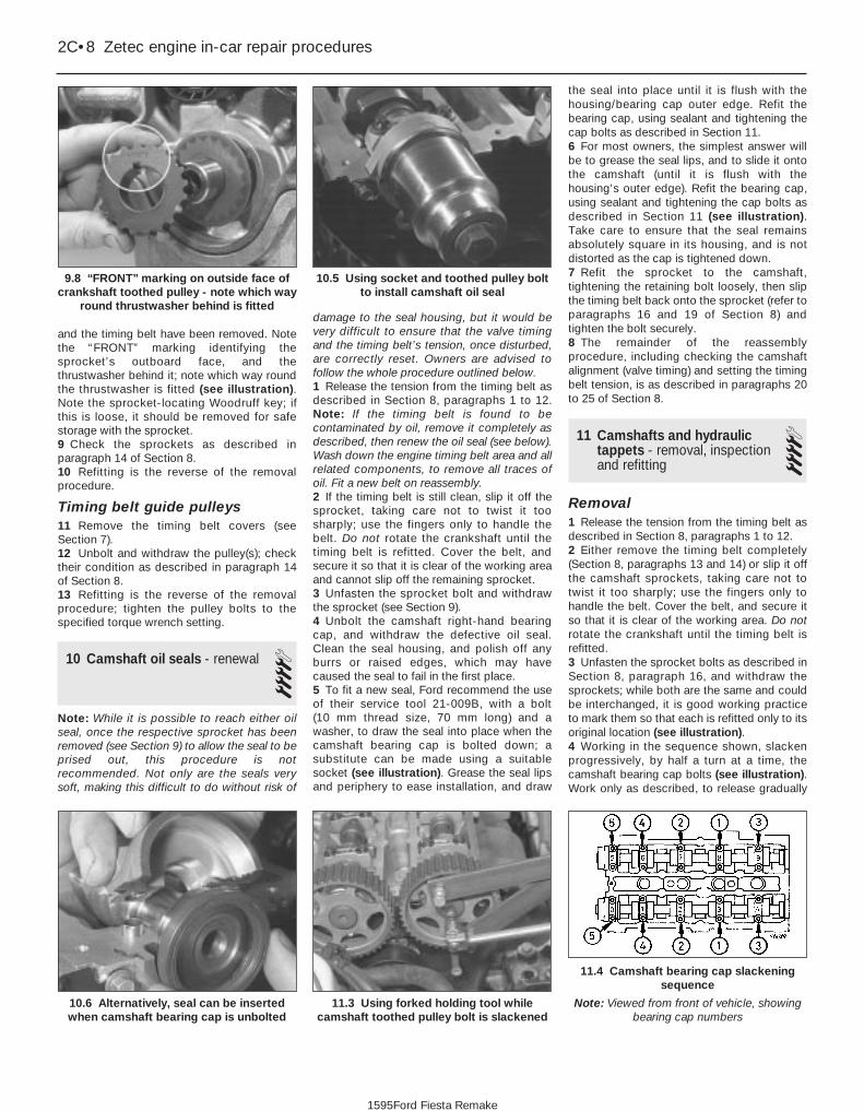
and the timing belt have been removed. Notethe “FRONT” marking identifying thesprocket’s outboard face, and thethrustwasher behind it; note which way roundthe thrustwasher is fitted (see illustration).Note the sprocket-locating Woodruff key; ifthis is loose, it should be removed for safestorage with the sprocket.9 Check the sprockets as described inparagraph 14 of Section 8.10 Refitting is the reverse of the removalprocedure.
Timing belt guide pulleys11 Remove the timing belt covers (seeSection 7).12 Unbolt and withdraw the pulley(s); checktheir condition as described in paragraph 14of Section 8.13 Refitting is the reverse of the removalprocedure; tighten the pulley bolts to thespecified torque wrench setting.
10 Camshaft oil seals - renewal 4Note: While it is possible to reach either oilseal, once the respective sprocket has beenremoved (see Section 9) to allow the seal to beprised out, this procedure is notrecommended. Not only are the seals verysoft, making this difficult to do without risk of
damage to the seal housing, but it would bevery difficult to ensure that the valve timingand the timing belt’s tension, once disturbed,are correctly reset. Owners are advised tofollow the whole procedure outlined below.1 Release the tension from the timing belt asdescribed in Section 8, paragraphs 1 to 12.Note: If the timing belt is found to becontaminated by oil, remove it completely asdescribed, then renew the oil seal (see below).Wash down the engine timing belt area and allrelated components, to remove all traces ofoil. Fit a new belt on reassembly.2 If the timing belt is still clean, slip it off thesprocket, taking care not to twist it toosharply; use the fingers only to handle thebelt. Do not rotate the crankshaft until thetiming belt is refitted. Cover the belt, andsecure it so that it is clear of the working areaand cannot slip off the remaining sprocket.3 Unfasten the sprocket bolt and withdrawthe sprocket (see Section 9).4 Unbolt the camshaft right-hand bearingcap, and withdraw the defective oil seal.Clean the seal housing, and polish off anyburrs or raised edges, which may havecaused the seal to fail in the first place.5 To fit a new seal, Ford recommend the useof their service tool 21-009B, with a bolt (10 mm thread size, 70 mm long) and awasher, to draw the seal into place when thecamshaft bearing cap is bolted down; asubstitute can be made using a suitablesocket (see illustration). Grease the seal lipsand periphery to ease installation, and draw
the seal into place until it is flush with thehousing/bearing cap outer edge. Refit thebearing cap, using sealant and tightening thecap bolts as described in Section 11.6 For most owners, the simplest answer willbe to grease the seal lips, and to slide it ontothe camshaft (until it is flush with thehousing’s outer edge). Refit the bearing cap,using sealant and tightening the cap bolts asdescribed in Section 11 (see illustration).Take care to ensure that the seal remainsabsolutely square in its housing, and is notdistorted as the cap is tightened down.7 Refit the sprocket to the camshaft,tightening the retaining bolt loosely, then slipthe timing belt back onto the sprocket (refer toparagraphs 16 and 19 of Section 8) andtighten the bolt securely.8 The remainder of the reassemblyprocedure, including checking the camshaftalignment (valve timing) and setting the timingbelt tension, is as described in paragraphs 20to 25 of Section 8.
11 Camshafts and hydraulictappets - removal, inspectionand refitting
4Removal1 Release the tension from the timing belt asdescribed in Section 8, paragraphs 1 to 12.2 Either remove the timing belt completely(Section 8, paragraphs 13 and 14) or slip it offthe camshaft sprockets, taking care not totwist it too sharply; use the fingers only tohandle the belt. Cover the belt, and secure itso that it is clear of the working area. Do notrotate the crankshaft until the timing belt isrefitted.3 Unfasten the sprocket bolts as described inSection 8, paragraph 16, and withdraw thesprockets; while both are the same and couldbe interchanged, it is good working practiceto mark them so that each is refitted only to itsoriginal location (see illustration).4 Working in the sequence shown, slackenprogressively, by half a turn at a time, thecamshaft bearing cap bolts (see illustration).Work only as described, to release gradually
2C•8 Zetec engine in-car repair procedures
11.4 Camshaft bearing cap slackeningsequence
Note: Viewed from front of vehicle, showingbearing cap numbers
11.3 Using forked holding tool whilecamshaft toothed pulley bolt is slackened
10.6 Alternatively, seal can be insertedwhen camshaft bearing cap is unbolted
10.5 Using socket and toothed pulley boltto install camshaft oil seal
9.8 “FRONT” marking on outside face ofcrankshaft toothed pulley - note which way
round thrustwasher behind is fitted
1595Ford Fiesta Remake

and evenly the pressure of the valve springson the caps.5 Withdraw the caps, noting their markingsand the presence of the locating dowels, thenremove the camshafts and withdraw their oilseals. The inlet camshaft can be identified bythe reference lobe for the camshaft positionsensor; therefore, there is no need to mark thecamshafts (see illustrations).6 Obtain sixteen small, clean containers, andnumber them 1 to 16. Using a rubber sucker,withdraw each hydraulic tappet in turn, invertit to prevent oil loss, and place it in itsrespective container, which should then befilled with clean engine oil (see illustrations).Do not interchange the hydraulic tappets, orthe rate of wear will be much increased. Donot allow them to lose oil, or they will take along time to refill on restarting the engine,resulting in incorrect valve clearances.
Inspection7 With the camshafts and hydraulic tappetsremoved, check each for signs of obviouswear (scoring, pitting etc) and for ovality, andrenew if necessary.8 Measure the outside diameter of eachtappet (see illustration) - take measurementsat the top and bottom of each tappet, then asecond set at right-angles to the first; if anymeasurement is significantly different from theothers, the tappet is tapered or oval and must
be renewed. If the necessary equipment isavailable, measure the inside diameter of thecorresponding cylinder head bore. Comparethe measurements obtained to those given in the Specifications Section of this Chapter; ifthe tappets or the cylinder head bores areexcessively worn, new tappets and/or a newcylinder head will be required.9 If the engine’s valve components havesounded noisy, particularly if the noisepersists after initial start-up from cold, there isreason to suspect a faulty hydraulic tappet.Only a good mechanic experienced in theseengines can tell whether the noise level istypical, or if renewal of one or more of thetappets is warranted. If faulty tappets arediagnosed, and the engine’s service history isunknown, it is always worth trying the effect ofrenewing the engine oil and filter (see Chap-ter 1), using only good-quality engine oil of therecommended viscosity and specification,before going to the expense of renewing anyof the tappets - refer also to the advice inSection 5 of this Chapter.10 Visually examine the camshaft lobes forscore marks, pitting, galling (wear due torubbing) and evidence of overheating (blue,discoloured areas). Look for flaking away ofthe hardened surface layer of each lobe. If anysuch signs are evident, renew the componentconcerned.
11 Examine the camshaft bearing journalsand the cylinder head bearing surfaces forsigns of obvious wear or pitting. If any suchsigns are evident, renew the componentconcerned.12 Using a micrometer, measure thediameter of each journal at several points. Ifthe diameter of any one journal is less thanthe specified value, renew the camshaft.13 To check the bearing journal runningclearance, remove the hydraulic tappets, usea suitable solvent and a clean lint-free rag toclean carefully all bearing surfaces, then refitthe camshafts and bearing caps with a strandof Plastigauge across each journal. Tightenthe bearing cap bolts to the specified torquewrench setting (do not rotate the camshafts),then remove the bearing caps and use thescale provided to measure the width of thecompressed strands. Scrape off thePlastigauge with your fingernail or the edge ofa credit card - don’t scratch or nick thejournals or bearing caps.14 If the running clearance of any bearing isfound to be worn to beyond the specifiedservice limits, fit a new camshaft and repeat the check; if the clearance is stillexcessive, the cylinder head must be renewed.15 To check camshaft endfloat, remove thehydraulic tappets, clean the bearing surfacescarefully, and refit the camshafts and bearing
Zetec engine in-car repair procedures 2C•9
11.6a Removing hydraulic tappets
11.5b Inlet camshaft has lobe for camshaft position sensor11.5a Note locating dowels when removing camshaft bearingcaps
11.8 Use a micrometer to measurediameter of hydraulic tappets
11.6b Hydraulic tappets must be stored asdescribed in text
2C
1595Ford Fiesta Remake

caps. Tighten the bearing cap bolts to thespecified torque wrench setting, thenmeasure the endfloat using a DTI (Dial TestIndicator, or dial gauge) mounted on thecylinder head so that its tip bears on thecamshaft right-hand end.16 Tap the camshaft fully towards the gauge,zero the gauge, then tap the camshaft fullyaway from the gauge, and note the gaugereading. If the endfloat measured is found tobe at or beyond the specified service limit, fita new camshaft and repeat the check; if theclearance is still excessive, the cylinder headmust be renewed.
Refitting17 On reassembly, liberally oil the cylinderhead hydraulic tappet bores and the tappets(see illustration). Note that if new tappets arebeing fitted, they must be charged with cleanengine oil before installation. Carefully refit thetappets to the cylinder head, ensuring thateach tappet is refitted to its original bore, andis the correct way up. Some care will berequired to enter the tappets squarely intotheir bores.18 Liberally oil the camshaft bearings andlobes. Ensuring that each camshaft is in itsoriginal location, refit the camshafts, locatingeach so that the slot in its left-hand end isapproximately parallel to, and just above, thecylinder head mating surface.19 Ensure that the locating dowels are
pressed firmly into their recesses, and checkthat all mating surfaces are completely clean,unmarked and free from oil. Apply a thin filmof suitable sealant (Ford recommend Loctite 518) to the mating surfaces of eachcamshaft’s right-hand bearing cap (seeillustration). Referring to paragraph 6 ofSection 10, some owners may wish to fit thenew camshaft oil seals at this stage.20 All camshaft bearing caps have a single-digit identifying number etched on them (seeillustration). The exhaust camshaft’s bearingcaps are numbered in sequence 0 to 4, theinlet’s 5 to 9; see illustration 11.21a for details.Each cap is to be fitted so that its numberedside faces outwards, to the front (exhaust) orto the rear (inlet).21 Ensuring that each cap is kept square tothe cylinder head as it is tightened down, andworking in the sequence shown, tighten thecamshaft bearing cap bolts slowly and by oneturn at a time, until each cap touches thecylinder head (see illustration). Next, goround again in the same sequence, tighteningthe bolts to the first stage torque wrenchsetting specified, then once more, tighteningthem to the second stage setting. Work onlyas described, to impose gradually and evenlythe pressure of the valve springs on the caps.Fit the camshaft-aligning tool; it should slipinto place as described in paragraph 8 ofSection 8 (see illustration).22 Wipe off all surplus sealant, so that noneis left to find its way into any oilways. Follow
the sealant manufacturer’s instructions as tothe time needed for curing; usually, at least anhour must be allowed between application ofthe sealant and starting the engine.23 If using Ford’s recommended procedure,fit new oil seals to the camshafts as describedin paragraph 5 of Section 10.24 Using the marks and notes made ondismantling to ensure that each is refitted toits original camshaft, refit the sprockets to thecamshafts, tightening the retaining boltsloosely. Slip the timing belt back onto thesprockets (refer to paragraph 19 of Section 8)and tighten the bolts securely - use the forkedholding tool described in paragraph 16 ofSection 8.25 The remainder of the reassemblyprocedure, including checking the camshaftalignment (valve timing) and setting the timingbelt tension, is as described in paragraphs 15to 25 of Section 8.
12 Cylinder head - removal and refitting 4
RemovalNote: The following text assumes that thecylinder head will be removed with both inletand exhaust manifolds attached. Thissimplifies the procedure, but makes it a bulkyand heavy assembly to handle - an enginehoist will be required, to prevent the risk ofinjury, and to prevent damage to any delicatecomponents as the assembly is removed andrefitted. If it is wished first to remove themanifolds, refer to Chapter 4D, then amendthe following procedure accordingly.1 Depressurise the fuel system (see Chap-ter 4D).2 Disconnect the battery negative (earth) lead(refer to Chapter 5A, Section 1).3 Refer to Chapter 4D and remove the airinlet components.4 Equalise the pressure in the fuel tank byremoving the filler cap, then undo the fuelfeed and return lines connecting the engine tothe chassis (see Chapter 4D). Plug or cap allopen fittings.
2C•10 Zetec engine in-car repair procedures
11.21b Fit camshaft-aligning tool to setTDC position while camshaft toothed
pulleys are refitted
11.21a Camshaft bearing cap tighteningsequence
Note: View from front of vehicle - locatebearing caps according to etched numbers,
aligned as described in text
11.20 Etched marks on camshaft bearingcaps must be arranged as shown, and face
outwards
11.19 Apply sealant to mating surface ofcamshaft right-hand bearing caps
11.17 Oil liberally when refitting hydraulictappets
1595Ford Fiesta Remake

5 Disconnect the accelerator cable from thethrottle linkage as described in Chapter 4D.Secure the cable clear of the engine/transmission.6 Remove the auxiliary drivebelt (see Chap-ter 1).7 Remove the three screws securing thewiring “rail” to the rear of the manifold.Releasing its wire clip, unplug the largeelectrical connector (next to the fuel pressureregulator) to disconnect the engine wiring fromthe main loom (see illustration). Unplug theelectrical connectors on each side of theignition coil, and the single connector frombeneath the front of the thermostat housing, todisconnect the coil and coolant temperaturegauge sender wiring (see illustration).8 Marking or labelling them as they areunplugged, disconnect the vacuum hoses asfollows:a) One from the rear of the throttle housing
(only the one hose - there is no need todisconnect the second hose running tothe fuel pressure regulator).
b) One from the union on the inlet manifold’sleft-hand end.
c) The braking system vacuum servo unithose (see Chapter 9 for details).
9 Unbolt the engine earth lead from thecylinder head lifting eye.10 Unbolt both parts of the exhaust manifoldheat shield. Either remove the dipstick andtube, or swing them out of the way.11 Unscrew the pulse-air filter housingretaining bolt, then disconnect its vacuumhose.12 Drain the cooling system (see Chapter 1).13 Disconnect all coolant hoses from thethermostat housing (see illustration).
14 Unscrew the two nuts to disconnect theexhaust system front downpipe from themanifold (Chapter 4B); disconnect the oxygensensor wiring, so that it is not strained by theweight of the exhaust system.15 Remove the timing belt and bothcamshafts (see Sections 8 and 11); if thecylinder head is to be dismantled, withdrawthe hydraulic tappets.16 Remove the timing belt inner shield (seeSection 7.17 Working in the reverse of the sequenceshown in illustration 12.28a, slacken the tencylinder head bolts progressively and by oneturn at a time; a Torx key (TX 55 size) will berequired. Remove each bolt in turn, andensure that new replacements are obtainedfor reassembly; these bolts are subjected tosevere stresses and so must be renewed,regardless of their apparent condition,whenever they are disturbed.18 Lift the cylinder head away; useassistance if possible, as it is a heavyassembly. If necessary, grip the manifoldsand rock it free from the location dowels onthe top face of the cylinder block. Do notattempt to tap it sideways or lever betweenthe head and the block top face. Remove thegasket, noting the two dowels, and discard it.
Preparation for refitting19 The mating faces of the cylinder head andcylinder block must be perfectly clean before
refitting the head. Use a hard plastic or woodscraper to remove all traces of gasket andcarbon; also clean the piston crowns. Takeparticular care during the cleaning operations,as aluminium alloy is easily damaged. Also,make sure that the carbon is not allowed toenter the oil and water passages - this isparticularly important for the lubricationsystem, as carbon could block the oil supplyto the engine’s components. Using adhesivetape and paper, seal the water, oil and boltholes in the cylinder block.
20 Check the mating surfaces of the cylinderblock and the cylinder head for nicks, deepscratches and other damage. If slight, theymay be removed carefully with a file, but ifexcessive, machining may be the onlyalternative to renewal.21 If warpage of the cylinder head gasketsurface is suspected, use a straight-edge tocheck it for distortion. Refer to Part D of thisChapter if necessary.
Refitting22 Wipe clean the mating surfaces of thecylinder head and cylinder block. Check thatthe two locating dowels are in position in thecylinder block, and that all cylinder head boltholes are free from oil.23 Position a new gasket over the dowels onthe cylinder block surface, so that the“TOP/OBEN” mark is uppermost, and with thetooth (or teeth, according to engine size)protruding from the front edge (seeillustration).24 Temporarily refit the crankshaft pulley,and rotate the crankshaft anti-clockwise sothat No 1 cylinder’s piston is lowered toapproximately 20 mm before TDC, thusavoiding any risk of valve/piston contact anddamage during reassembly.
Zetec engine in-car repair procedures 2C•11
12.13 Disconnect all coolant hoses fromthermostat housing
12.7b Unplug connectors (arrowed) todisconnect ignition coil wiring
12.7a Unplug engine wiring loomconnector alongside the inlet manifold
12.23 Ensuring protruding tooth (or teeth)“A” are at front and marking “B” is
upwards, locate new cylinder head gasketon dowels “C”
2C
1595Ford Fiesta Remake
Whenever you disconnectany vacuum lines, coolant oremissions hoses, wiringconnectors and fuel lines,
always label them clearly, so that theycan be correctly reassembled. Maskingtape and/or a touch-up paint applicatorwork well for marking items. Takeinstant photos, or sketch the locationsof components and brackets.
To prevent carbon enteringthe gap between the pistonsand bores, smear a littlegrease in the gap. After
cleaning each piston, use a small brushto remove all traces of grease andcarbon from the gap, then wipe awaythe remainder with a clean rag.

25 As the cylinder head is such a heavy andawkward assembly to refit with manifolds, it ishelpful to make up a pair of guide studs fromtwo 10 mm (thread size) studs approximately90 mm long, with a screwdriver slot cut in oneend - two old cylinder head bolts with theirheads cut off would make a good startingpoint. Screw these guide studs, screwdriverslot upwards to permit removal, into the boltholes at diagonally-opposite corners of thecylinder block surface (or into those where thelocating dowels are fitted); ensure thatapproximately 70 mm of stud protrudesabove the gasket.26 Refit the cylinder head, sliding it down theguide studs (if used) and locating it on thedowels. Unscrew the guide studs (if used)when the head is in place.27 Fit the new cylinder head bolts dry (do notoil their threads); carefully enter each into itshole and screw it in, by hand only, until finger-tight.28 Working progressively and in thesequence shown, use first a torque wrench,then an ordinary socket extension bar and anangle gauge, to tighten the cylinder head boltsin the stages given in the SpecificationsSection of this Chapter (see illustrations).Note: Once tightened correctly, following thisprocedure, the cylinder head bolts do notrequire check-tightening, and must not be re-torqued.29 Refit the hydraulic tappets (if removed),the camshafts, their oil seals and sprockets(see Sections 11, 10 and 9, as appropriate).Temporarily refit the crankshaft pulley, androtate the crankshaft clockwise to return thepulley notches to the TDC position describedin Section 3.30 Refit the earth lead to the lifting eye31 Refit the timing belt and covers, checkingthe camshaft alignment (valve timing) andsetting the timing belt tension, as described inSection 8.32 The remainder of reassembly is thereverse of the removal procedure, noting thefollowing points:a) Tighten all fasteners to the torque wrench
settings specified.b) Refill the cooling system, and top-up the
engine oil (see Chapter 1 and “WeeklyChecks”).
c) Check all disturbed joints for signs of oilor coolant leakage, once the engine hasbeen restarted and warmed-up to normaloperating temperature.
d) If the power steering hoses wheredisconnected, bleed the system asdescribed in Chapter 10 afterreconnection.
13 Sump - removal and refitting 2
RemovalNote: The full procedure outlined below mustbe followed, so that the mating surfaces canbe cleaned and prepared to achieve an oil-tight joint on reassembly, and so that thesump can be aligned correctly; depending onyour skill and experience, and the tools andfacilities available, it may be that this task canbe carried out only with the engine removedfrom the vehicle. Note that the sump gasketmust be renewed whenever it is disturbed.1 Disconnect the battery negative (earth) lead(refer to Chapter 5A, Section 1).2 Drain the engine oil, then clean and refit theengine oil drain plug, tightening it to thespecified torque wrench setting. Although notstrictly necessary as part of the dismantlingprocedure, owners are advised to remove anddiscard the oil filter, so that it can be renewedwith the oil (see Chapter 1).3 Refer to Chapter 5A and remove the startermotor.4 Remove the auxiliary drivebelt cover (seeChapter 1).5 Unplug the electrical connector(s) todisconnect the oxygen sensor.6 Unscrew the nuts to disconnect theexhaust system front downpipe from themanifold, then either unhook all the system’srubber mountings and withdraw the completeexhaust system from under the vehicle, orremove only the downpipe/catalytic converter(see Chapter 4E for details).
7 Unscrew the sump-to-transmission bolts,also any securing the engine/transmissionlower adapter plate.8 Progressively unscrew the sump retainingbolts. Break the joint by striking the sump withthe palm of the hand, then lower the sumpand withdraw it with the engine/transmissionlower adapter plate (where fitted); note thepresence of any shims between the sump andtransmission.9 Remove and discard the sump gasket; thismust be renewed as a matter of coursewhenever it is disturbed.10 While the sump is removed, take theopportunity to remove the oil pump pick-up/strainer pipe and to clean it (see Sec-tion 14).
Refitting11 On reassembly, thoroughly clean anddegrease the mating surfaces of the cylinderblock/crankcase and sump, then use a cleanrag to wipe out the sump and the engine’sinterior. If the oil pump pick-up/strainer pipewas removed, fit a new gasket and refit thepipe, tightening its screws to the specifiedtorque wrench setting. Fit the new gasket tothe sump mating surface so that the gasketfits into the sump groove (see illustration).12 If the sump is being refitted with theengine/transmission still connected and in thevehicle, proceed as follows:a) Check that the mating surfaces of the
sump, the cylinder block/crankcase and
2C•12 Zetec engine in-car repair procedures
13.11 Ensure gasket is located correctly insump groove
12.28c . . . and to Stage 3 using anglegauge
12.28b Tightening cylinder head bolts(Stages 1 and 2) using torque wrench . . .
12.28a Cylinder head bolt tighteningsequence
Note: View from rear of vehicle
1595Ford Fiesta Remake

the transmission are absolutely clean andflat. Any shims found on removal of thesump must be refitted in their originallocations.
b) Apply a thin film of suitable sealant (Fordrecommend Hylosil 102) to the junctionsof the cylinder block/crankcase with theoil pump and the crankshaft left-hand oilseal carrier. Without delay - the sumpbolts must be fully tightened within 10 to20 minutes of applying the sealant - offerup the sump and engine/transmissionlower adapter plate, and refit the bolts,tightening them lightly at first.
c) Ensuring that the engine/transmissionlower adapter plate is correctly located,firmly press the sump against thetransmission, and tighten thetransmission-to-sump (ie, engine) bolts tothe specified torque wrench setting.
d) Without disturbing the position of thesump, and working in a diagonalsequence from the centre outwards,tighten the sump bolts to the specifiedtorque wrench setting.
e) Proceed to paragraph 14.13 If the sump is being refitted with theengine and transmission separated (in or outof the vehicle), proceed as follows:a) Apply a thin film of suitable sealant (Ford
recommend Hylosil 102) to the junctionsof the cylinder block/crankcase with theoil pump and the crankshaft left-hand oil
seal carrier (see illustration). Without delay- the sump bolts must be fully tightenedwithin 10 to 20 minutes of applying thesealant - offer up the sump to the cylinderblock/crankcase, and insert the sumpbolts, tightening them lightly at first.
b) Using a suitable straight edge to checkalignment across the flat-machined facesof each, move the sump as necessary sothat its left-hand face - including anyshims found on removal - is flush withthat of the cylinder block/crankcase (seeillustration). Without disturbing theposition of the sump, and working in adiagonal sequence from the centreoutwards, tighten the sump bolts to thespecified torque wrench setting.
c) Check again that both faces are flushbefore proceeding; if necessary, unboltthe sump again, clean the matingsurfaces, and repeat the full procedure toensure that the sump is correctly aligned.
d) If it is not possible to achieve exactalignment by moving the sump, shims areavailable in thicknesses of 0.25 mm(colour-coded yellow) or 0.50 mm (colour-coded black) to eliminate the discrepancy(see illustration).
14 The remainder of reassembly is thereverse of the removal procedure, noting thefollowing points.a) Tighten all fasteners to the torque wrench
settings specified.
b) Always renew any self-locking nutsdisturbed on removal.
c) Refill the cooling system (see Chapter 1).d) Refill the engine with oil, remembering
that you are advised to fit a new filter (seeChapter 1).
e) Check for signs of oil or coolant leaksonce the engine has been restarted andwarmed-up to normal operatingtemperature.
14 Oil pump - removal,inspection and refitting 4
RemovalNote: While this task is theoretically possiblewhen the engine is in place in the vehicle, inpractice, it requires so much preliminarydismantling, and is so difficult to carry out dueto the restricted access, that owners areadvised to remove the engine from the vehiclefirst. Note, however, that the oil pumppressure relief valve can be removed with theengine in situ - see paragraph 8.1 Remove the timing belt (see Section 8).2 Withdraw the crankshaft sprocket and thethrustwasher behind it, noting which wayround the thrustwasher is fitted (see Sec-tion 9).3 Remove the sump (see Section 13).4 Undo the screws securing the oil pumppick-up/strainer pipe to the pump, thenunscrew the nut and withdraw the oil pumppick-up/strainer pipe. Discard the gasket.5 Unbolt the pump from the cylinderblock/crankcase (see illustration). Withdrawand discard the gasket, and remove thecrankshaft right-hand oil seal. Thoroughlyclean and degrease all components,particularly the mating surfaces of the pump,the sump, and the cylinder block/crankcase.
Inspection6 Unscrew the Torx screws, and remove thepump cover plate; noting any identificationmarks on the rotors, withdraw the rotors (seeillustration).
Zetec engine in-car repair procedures 2C•13
13.13c Sump-to-cylinder block/crankcasealignment shims
1 Fitting points on sump 2 Shim
13.13b Checking alignment of sump withcylinder block/crankcase
13.13a Apply sealant (arrowed) as directedwhen refitting sump
14.6 Withdrawing oil pump inner rotor14.5 Unscrew bolts (arrowed) to removeoil pump
2C
1595Ford Fiesta Remake

7 Inspect the rotors for obvious signs of wearor damage, and renew if necessary; if eitherrotor, the pump body, or its cover plate arescored or damaged, the complete oil pumpassembly must be renewed.8 The oil pressure relief valve can bedismantled, if required, without disturbing thepump. Chock the rear wheels then jack up thefront of the car and support it on axle stands(see “Jacking and Vehicle Support”). Removethe front right-hand roadwheel and auxiliarydrivebelt cover (see Chapter 1) to provideaccess to the valve.9 Unscrew the threaded plug, and recoverthe valve spring and plunger (seeillustrations). If the plug’s sealing O-ring isworn or damaged, a new one must beobtained, to be fitted on reassembly.10 Reassembly is the reverse of the
dismantling procedure; ensure the spring andvalve are refitted the correct way round, andtighten the threaded plug securely.
Refitting11 The oil pump must be primed oninstallation, by pouring clean engine oil into it,and rotating its inner rotor a few turns.12 Using grease to stick the new gasket inplace on the cylinder block/crankcase, androtating the pump’s inner rotor to align withthe flats on the crankshaft, refit the pump andinsert the bolts, tightening them lightly at first(see illustration).13 Using a suitable straight edge and feelergauges, check that the pump is both centredexactly around the crankshaft, and alignedsquarely so that its (sump) mating surface isexactly the same amount - between 0.3 and0.8 mm - below that of the cylinderblock/crankcase on each side of thecrankshaft (see illustration). Being carefulnot to disturb the gasket, move the pump intothe correct position, and tighten its bolts to the specified torque wrench setting.14 Check that the pump is correctly located;if necessary, unbolt it again, and repeat thefull procedure to ensure that the pump iscorrectly aligned.15 Fit a new crankshaft right-hand oil seal(see Section 15).16 Using grease to stick the gasket in placeon the pump, refit the pick-up/strainer pipe,tightening its screws and nut to their specifiedtorque wrench settings (see illustration).
17 The remainder of reassembly is thereverse of the removal procedure, referring tothe relevant text for details where required.
15 Crankshaft oil seals - renewal 4
Note: Don’t try to prise these seals out withoutremoving the oil pump or seal carrier - theseals are too soft, and the amount of spaceavailable is too small, for this to be possiblewithout considerable risk of damage to the sealhousing and/or the crankshaft journal. Followexactly the procedure given below.
Right-hand seal1 Remove the oil pump (see Section 14).2 Drive the oil seal out of the pump frombehind (see illustration).3 Clean the seal housing and crankshaft,polishing off any burrs or raised edges, whichmay have caused the seal to fail in the firstplace.4 Refit the oil pump (see Section 14). Greasethe lips and periphery of the new seal, to easeinstallation.5 To fit a new seal, Ford recommend the useof their service tool 21-093A, with thecrankshaft pulley bolt, to draw the seal intoplace; an alternative can be arranged using asocket of suitable size, with a washer tomatch the crankshaft pulley bolt (seeillustration).
2C•14 Zetec engine in-car repair procedures
15.5 Socket of correct size can be used toreplace Ford service tool, drawing new
seal into place as described15.2 Driving out crankshaft right-hand oil
seal14.16 Use new gasket when refitting oil
pick-up pipe to pump
14.13 Oil pump must be positionedaccurately
14.12 Use new gasket when refitting oilpump
14.9b . . . to withdraw oil pressure reliefvalve spring and plunger
14.9a Unscrew threaded plug - seenthrough right-hand wheel arch . . .
1595Ford Fiesta Remake

6 If such tools are not available, press theseal squarely into place by hand; tap it in untilit is flush with the pump housing, using a soft-faced mallet and a socket with an outsidediameter only slightly smaller than the seal’s(see illustration). This approach requiresgreat care, to ensure that the seal is fittedsquarely, without distortion or damage.7 Wash off any traces of oil. The remainder ofreassembly is the reverse of the removalprocedure, referring to the relevant text fordetails where required. Check for signs of oilleakage when the engine is restarted.
Left-hand seal8 Remove the transmission (see the relevantPart of Chapter 7).9 Where appropriate, remove the clutch(Chapter 6).10 Unbolt the flywheel/driveplate (seeSection 17).11 Remove the sump (see Section 13).12 Unbolt the oil seal carrier (seeillustration). Remove and discard its gasket.13 Supporting the carrier evenly on woodenblocks, drive the oil seal out of the carrier frombehind (see illustration).14 Clean the seal housing and crankshaft,polishing off any burrs or raised edges, whichmay have caused the seal to fail in the firstplace. Clean also the mating surfaces of thecylinder block/crankcase and carrier, using a
scraper to remove all traces of the old gasket- be careful not to scratch or damage thematerial of either - then use a suitable solventto degrease them.15 Use grease to stick the new gasket inplace on the cylinder block/crankcase, thenoffer up the carrier (see illustration).16 Using a suitable straight edge and feelergauges, check that the carrier is both centredexactly around the crankshaft, and alignedsquarely so that its (sump) mating surface isexactly the same amount - between 0.3 and0.8 mm - below that of the cylinderblock/crankcase on each side of thecrankshaft (see illustration). Being carefulnot to disturb the gasket, move the carrier intothe correct position, and tighten its bolts tothe specified torque wrench setting.17 Check that the carrier is correctly located;if necessary, unbolt it again, and repeat thefull procedure to ensure that the carrier iscorrectly aligned.18 Ford’s recommended method of sealfitting is to use service tool 21-141, with twoflywheel bolts to draw the seal into place. Ifthis is not available, make up a guide from athin sheet of plastic or similar, lubricate thelips of the new seal and the crankshaftshoulder with grease, then offer up the seal,with the guide feeding the seal’s lips over thecrankshaft shoulder (see illustration). Pressthe seal evenly into its housing by hand only,
and use a soft-faced mallet gently to tap itinto place until it is flush with the surroundinghousing.19 Wipe off any surplus oil or grease; theremainder of the reassembly procedure is thereverse of dismantling, referring to the relevanttext for details where required. Check for signsof oil leakage when the engine is restarted.
16 Engine/transmissionmountings - inspection and renewal 1
Inspection1 The engine/transmission mountings seldomrequire attention, but broken or deterioratedmountings should be renewed immediately, orthe added strain placed on the drivelinecomponents may cause damage or wear.2 During the check, the engine/transmissionmust be raised slightly, to remove its weightfrom the mountings.3 Chock the rear wheels then jack up thefront of the car and support it on axle stands(see “Jacking and Vehicle Support”). Positiona jack under the sump, with a large block ofwood between the jack head and the sump,then carefully raise the engine/transmissionjust enough to take the weight off themountings.
Zetec engine in-car repair procedures 2C•15
15.13 . . . and ensure that carrier isproperly supported when driving out usedoil seal - note notches provided in carrier
for drift
15.12 Unscrew bolts (arrowed) to removecrankshaft left-hand oil seal carrier . . .
15.6 If seal is tapped into place as shown,exercise great care to prevent seal from
being damaged or distorted
15.18 Using guide made from thin sheet ofplastic to slide oil seal lips over crankshaft
shoulder
15.16 Oil seal carrier must be positionedaccurately
15.15 Use new gasket when refitting left-hand oil seal carrier
2C
1595Ford Fiesta Remake

4 Check the mountings to see if the rubber iscracked, hardened or separated from themetal components. Sometimes, the rubberwill split right down the centre.5 Check for relative movement between eachmounting’s brackets and the engine/transmission or body (use a large screwdriveror lever to attempt to move the mountings). Ifmovement is noted, lower the engine andcheck-tighten the mounting fasteners.
Renewal6 The engine mountings can be removed ifthe weight of the engine/transmission issupported by one of the following alternativemethods.7 Either support the weight of the assemblyfrom underneath using a jack and a suitablepiece of wood between the jack saddle andthe sump or transmission (to preventdamage), or from above by attaching a hoistto the engine. A third method is to use asuitable support bar with end pieces whichwill engage in the water channel each side ofthe bonnet lid aperture. Using an adjustablehook and chain connected to the engine, theweight of the engine and transmission canthen be taken from the mountings.
Engine front right-hand mounting8 This mounting consists of a two-piecebracket bolted to the inner wing panel,connected by the bonded-rubber mountingitself to a (Y-shaped) bracket, bolted (via thealternator mounting bracket) to the cylinderblock (see illustration).9 Unscrew the three bolts securing the frontright-hand mounting bracket to the alternatormounting bracket.10 Unscrew the bolts securing the mountingbracket to the inner wing panel and chassisrail and withdraw the mounting assembly.
Engine rear right-hand mounting11 This mounting consists of the bonded-rubber mounting secured to the inner wingpanel by a (horizontal) bolt, accessible fromwithin the wheel arch, and a (vertical) stud, theretaining nut of which is accessible from theengine compartment. The mounting is boltedto a bracket, which is in turn bolted to thecylinder block.12 Unbolt the mounting from the body byunscrewing first the single nut (and washer)immediately to the rear of the timing beltcover, then the bolt in the wheel arch.13 Unbolt the mounting from the cylinderblock bracket and withdraw the mountingassembly.
Transmission bearer and mountings14 On XR2i models, remove the frontsuspension crossmember as described inChapter 10.15 Unscrew and remove the two nutssecuring the mountings (front and rear) to thetransmission bearer16 Support the transmission bearer, thenundo and remove the four retaining bolts fromthe floorpan, two at the front and two at therear, and lower the transmission bearer fromthe vehicle. Note plate fitment, as applicable,for reassembly.17 To remove the mountings from thetransmission, unscrew the upper bolt andlower stud (front mounting) or the three nuts(rear mounting) and withdraw the relevantmounting and bracket assembly from thetransmission.
All mountings18 Refitting of all mountings is a reversal ofremoval. Make sure that the original sequenceof assembly of washers and plates ismaintained.19 Do not fully tighten any mounting boltsuntil they are all located. As the mountingbolts and nuts are tightened, check that themounting rubbers do not twist.
17 Flywheel/driveplate -removal, inspection andrefitting
3Removal1 Remove the transmission (see the relevantPart of Chapter 7).2 Where appropriate, remove the clutch(Chapter 6).3 Use a centre-punch or paint to make
alignment marks on the flywheel/driveplateand crankshaft, to ensure correct alignmentduring refitting.4 Prevent the flywheel/driveplate from turningby locking the ring gear teeth, or by bolting astrap between the flywheel/driveplate and thecylinder block/crankcase. Slacken the boltsevenly until all are free.5 Remove each bolt in turn, and ensure thatnew replacements are obtained forreassembly; these bolts are subjected tosevere stresses, and so must be renewed,regardless of their apparent condition,whenever they are disturbed.6 Noting the reinforcing plate (automatictransmission models only), withdraw theflywheel/driveplate; do not drop it - it is veryheavy.
Inspection7 Clean the flywheel/driveplate to removegrease and oil. Inspect the surface for cracks,rivet grooves, burned areas and score marks.Light scoring can be removed with emerycloth. Check for cracked and broken ring gearteeth. Lay the flywheel/driveplate on a flatsurface, and use a straight edge to check forwarpage.8 Clean and inspect the mating surfaces ofthe flywheel/driveplate and the crankshaft. Ifthe crankshaft left-hand seal is leaking, renewit (see Section 15) before refitting theflywheel/driveplate.9 While the flywheel/driveplate is removed,clean carefully its inboard (right-hand) face,particularly the recesses which serve as thereference points for the crankshaft speed/position sensor. Clean the sensor’s tip, andcheck that the sensor is securely fastened.
Refitting10 On refitting, ensure that the engine/transmission adapter plate is in place (wherenecessary), then fit the flywheel/driveplate tothe crankshaft so that all bolt holes align - itwill fit only one way - check this using themarks made on removal. Do not forget thereinforcing plate (automatic transmissionmodels).11 Lock the flywheel/driveplate by themethod used on dismantling. Working in adiagonal sequence to tighten them evenly,and increasing to the final amount in two orthree stages, tighten the new bolts to thespecified torque wrench setting.12 The remainder of reassembly is thereverse of the removal procedure, referring tothe relevant text for details where required.
2C•16 Zetec engine in-car repair procedures
16.8 Engine front right-hand mounting
1595Ford Fiesta Remake

2D
1595Ford Fiesta Remake
HCS engines
Cylinder headMaximum permissible gasket surface distortion (measured overfull length) . . . . . . . . . . . . . . . . . . . . . . . . . . . . . . . . . . . . . . . . . . . . . . . . 0.15 mmValve seat angle (inlet and exhaust) . . . . . . . . . . . . . . . . . . . . . . . . . . . . 45ºValve seat width (inlet and exhaust) . . . . . . . . . . . . . . . . . . . . . . . . . . . . 1.18 to 1.75 mm**The inlet and exhaust valves have special inserts which cannot be recut using conventional tools.
Valves - general Inlet ExhaustValve length . . . . . . . . . . . . . . . . . . . . . . . . . . . . . . . . . . . . . . . . . . . . . . 103.7 to 104.4 mm 104.2 to 104.7 mmValve head diameter:
1.0 and 1.1 litre engines . . . . . . . . . . . . . . . . . . . . . . . . . . . . . . . . . . . 32.90 to 33.10 mm 28.90 to 29.10 mm1.3 litre engines . . . . . . . . . . . . . . . . . . . . . . . . . . . . . . . . . . . . . . . . . . 34.40 to 34.60 mm 28.90 to 29.10 mm
Valve stem diameter . . . . . . . . . . . . . . . . . . . . . . . . . . . . . . . . . . . . . . . . 7.0 mm 7.0 mmValve stem-to-guide clearance . . . . . . . . . . . . . . . . . . . . . . . . . . . . . . . . 0.020 to 0.069 0.046 to 0.095
Cylinder blockCylinder bore diameter:
1.0 and 1.1 litre engines:Standard class 1 (or A) . . . . . . . . . . . . . . . . . . . . . . . . . . . . . . . . . . 68.68 to 68.69 mmStandard class 2 (or B) . . . . . . . . . . . . . . . . . . . . . . . . . . . . . . . . . . 68.69 to 68.70 mmStandard class 3 (or C) . . . . . . . . . . . . . . . . . . . . . . . . . . . . . . . . . . 68.70 to 68.71 mmOversize 0.5 mm . . . . . . . . . . . . . . . . . . . . . . . . . . . . . . . . . . . . . . . 69.20 to 69.21 mmOversize 1.0 mm . . . . . . . . . . . . . . . . . . . . . . . . . . . . . . . . . . . . . . . 69.70 to 69.71 mm
1.3 litre engines:Standard class 1 . . . . . . . . . . . . . . . . . . . . . . . . . . . . . . . . . . . . . . . 73.94 to 73.95 mmStandard class 2 . . . . . . . . . . . . . . . . . . . . . . . . . . . . . . . . . . . . . . . 73.50 to 73.96 mmStandard class 3 . . . . . . . . . . . . . . . . . . . . . . . . . . . . . . . . . . . . . . . 73.96 to 73.97 mmOversize 0.5 mm . . . . . . . . . . . . . . . . . . . . . . . . . . . . . . . . . . . . . . . 74.50 to 74.51 mmOversize 1.0 mm . . . . . . . . . . . . . . . . . . . . . . . . . . . . . . . . . . . . . . . 75.00 to 75.01 mm
Chapter 2 Part D:Engine removal and overhaul procedures
Camshaft and tappets - removal, inspection and refitting (HCS engines) . . . . . . . . . . . . . . . . . . . . . . . . . . . . . . . . . . . . . . . . 10
Crankshaft - refitting and main bearing running clearance check . . . . . . . . . . . . . . . . . . . . . . . . . . . . . . . . . . . . . . . . . . . . . . . 17
Crankshaft - removal and inspection . . . . . . . . . . . . . . . . . . . . . . . . 12Cylinder block/crankcase - cleaning and inspection . . . . . . . . . . . . 13Cylinder head - dismantling . . . . . . . . . . . . . . . . . . . . . . . . . . . . . . . 7Cylinder head - reassembly . . . . . . . . . . . . . . . . . . . . . . . . . . . . . . . 9Cylinder head and valve components - cleaning and inspection . . . 8Engine - initial start-up after overhaul . . . . . . . . . . . . . . . . . . . . . . . . 19Engine - removal and refitting (HCS engines) . . . . . . . . . . . . . . . . . . 3Engine overhaul - preliminary information . . . . . . . . . . . . . . . . . . . . . 6
Engine overhaul - reassembly sequence . . . . . . . . . . . . . . . . . . . . . 15Engine/transmission removal - preparation and precautions . . . . . . 2Engine/transmission - removal and refitting (CVH and
PTE engines) . . . . . . . . . . . . . . . . . . . . . . . . . . . . . . . . . . . . . . . . . 4Engine/transmission - removal and refitting (Zetec engines) . . . . . . 5General information . . . . . . . . . . . . . . . . . . . . . . . . . . . . . . . . . . . . . . 1Main and big-end bearings - inspection . . . . . . . . . . . . . . . . . . . . . . 14Piston/connecting rod assemblies - refitting and big-end
bearing running clearance check . . . . . . . . . . . . . . . . . . . . . . . . . 18Piston/connecting rod assemblies - removal and inspection . . . . . . 11Piston rings - refitting . . . . . . . . . . . . . . . . . . . . . . . . . . . . . . . . . . . . 16
2D•1
Specifications
Contents
Easy, suitable fornovice with littleexperience
Fairly easy, suitablefor beginner withsome experience
Fairly difficult,suitable for competentDIY mechanic
Difficult, suitable forexperienced DIYmechanic
Very difficult,suitable for expert DIYor professional
Degrees of difficulty
54321

Pistons and piston ringsPiston diameter:
1.0 and 1.1 litre engines:Standard class 1 (or A) . . . . . . . . . . . . . . . . . . . . . . . . . . . . . . . . . . 68.65 to 68.66 mmStandard class 2 (or B) . . . . . . . . . . . . . . . . . . . . . . . . . . . . . . . . . . 68.66 to 68.67 mmStandard class 3 (or C) . . . . . . . . . . . . . . . . . . . . . . . . . . . . . . . . . . 68.67 to 68.68 mmStandard (service) . . . . . . . . . . . . . . . . . . . . . . . . . . . . . . . . . . . . . . 68.67 to 68.70 mmOversize 0.5 mm . . . . . . . . . . . . . . . . . . . . . . . . . . . . . . . . . . . . . . . 69.16 to 69.19 mmOversize 1.0 mm . . . . . . . . . . . . . . . . . . . . . . . . . . . . . . . . . . . . . . . 69.66 to 69.69 mm
1.3 litre engines:Standard class 1 . . . . . . . . . . . . . . . . . . . . . . . . . . . . . . . . . . . . . . . 73.91 to 73.92 mmStandard class 2 . . . . . . . . . . . . . . . . . . . . . . . . . . . . . . . . . . . . . . . 73.92 to 73.93 mmStandard class 3 . . . . . . . . . . . . . . . . . . . . . . . . . . . . . . . . . . . . . . . 73.93 to 73.94 mmOversize 0.5 mm . . . . . . . . . . . . . . . . . . . . . . . . . . . . . . . . . . . . . . . 74.46 to 74.49 mmOversize 1.0 mm . . . . . . . . . . . . . . . . . . . . . . . . . . . . . . . . . . . . . . . 74.96 to 74.99 mm
Piston-to-cylinder bore clearance . . . . . . . . . . . . . . . . . . . . . . . . . . . . . 0.015 to 0.050 mmPiston ring end gap - installed:
Top compression ring . . . . . . . . . . . . . . . . . . . . . . . . . . . . . . . . . . . . . 0.25 to 0.45 mmSecond compression ring:
1.0 and 1.1 litre engines . . . . . . . . . . . . . . . . . . . . . . . . . . . . . . . . . 0.25 to 0.45 mm1.3 litre engines . . . . . . . . . . . . . . . . . . . . . . . . . . . . . . . . . . . . . . . . 0.45 to 0.75 mm
Oil control ring . . . . . . . . . . . . . . . . . . . . . . . . . . . . . . . . . . . . . . . . . . 0.20 to 0.40 mmPiston ring-to-groove clearance:
Compression rings . . . . . . . . . . . . . . . . . . . . . . . . . . . . . . . . . . . . . . . 0.20 mm (maximum)Oil control ring . . . . . . . . . . . . . . . . . . . . . . . . . . . . . . . . . . . . . . . . . . 0.10 mm (maximum)
Ring gap position:Top compression ring . . . . . . . . . . . . . . . . . . . . . . . . . . . . . . . . . . . . . Offset 180º from oil control ring gapSecond compression ring . . . . . . . . . . . . . . . . . . . . . . . . . . . . . . . . . . Offset 90º from oil control ring gapOil control ring . . . . . . . . . . . . . . . . . . . . . . . . . . . . . . . . . . . . . . . . . . Aligned with gudgeon pin
Gudgeon pinLength:
1.0 and 1.1 litre engines . . . . . . . . . . . . . . . . . . . . . . . . . . . . . . . . . . . 58.6 to 59.4 mm1.3 litre engines . . . . . . . . . . . . . . . . . . . . . . . . . . . . . . . . . . . . . . . . . . 63.3 to 64.6 mm
Diameter:White colour code . . . . . . . . . . . . . . . . . . . . . . . . . . . . . . . . . . . . . . . . 18.026 to 18.029 mmRed colour code . . . . . . . . . . . . . . . . . . . . . . . . . . . . . . . . . . . . . . . . . 18.029 to 18.032 mmBlue colour code . . . . . . . . . . . . . . . . . . . . . . . . . . . . . . . . . . . . . . . . . 18.032 to 18.035 mmYellow colour code . . . . . . . . . . . . . . . . . . . . . . . . . . . . . . . . . . . . . . . 18.035 to 18.038 mm
Clearance in piston . . . . . . . . . . . . . . . . . . . . . . . . . . . . . . . . . . . . . . . . . 0.008 to 0.014 mmInterference fit in connecting rod . . . . . . . . . . . . . . . . . . . . . . . . . . . . . . 0.016 to 0.048 mm
Crankshaft and bearingsMain bearing journal diameter:
1.0 and 1.1 litre engines:Standard . . . . . . . . . . . . . . . . . . . . . . . . . . . . . . . . . . . . . . . . . . . . . 56.990 to 57.000 mmStandard (with yellow line) . . . . . . . . . . . . . . . . . . . . . . . . . . . . . . . 56.980 to 56.990 mm0.254 mm undersize (with green line) . . . . . . . . . . . . . . . . . . . . . . . 56.726 to 56.746 mm0.508 mm undersize (service) . . . . . . . . . . . . . . . . . . . . . . . . . . . . . 56.472 to 56.492 mm0.762 mm undersize (service) . . . . . . . . . . . . . . . . . . . . . . . . . . . . . 56.218 to 56.238 mm
1.3 litre engines:Standard . . . . . . . . . . . . . . . . . . . . . . . . . . . . . . . . . . . . . . . . . . . . . 56.980 to 57.000 mm0.254 mm undersize (with green line) . . . . . . . . . . . . . . . . . . . . . . . 56.726 to 56.746 mm0.508 mm undersize (service) . . . . . . . . . . . . . . . . . . . . . . . . . . . . . 56.472 to 56.492 mm0.762 mm undersize (service) . . . . . . . . . . . . . . . . . . . . . . . . . . . . . 56.218 to 56.238 mm
Main bearing journal-to-shell running clearance:1.0 and 1.1 litre engines . . . . . . . . . . . . . . . . . . . . . . . . . . . . . . . . . . . 0.009 to 0.046 mm1.3 litre engines . . . . . . . . . . . . . . . . . . . . . . . . . . . . . . . . . . . . . . . . . . 0.009 to 0.056 mm
Crankpin (big-end) bearing journal diameter:Standard . . . . . . . . . . . . . . . . . . . . . . . . . . . . . . . . . . . . . . . . . . . . . . . 40.99 to 41.01 mm0.254 mm undersize . . . . . . . . . . . . . . . . . . . . . . . . . . . . . . . . . . . . . . 40.74 to 40.76 mm0.508 mm undersize . . . . . . . . . . . . . . . . . . . . . . . . . . . . . . . . . . . . . . 40.49 to 40.51 mm0.762 mm undersize . . . . . . . . . . . . . . . . . . . . . . . . . . . . . . . . . . . . . . 40.24 to 40.26 mm
Crankpin (big-end) bearing journal-to-shell running clearance . . . . . . . 0.006 to 0.060 mmCrankshaft endfloat . . . . . . . . . . . . . . . . . . . . . . . . . . . . . . . . . . . . . . . . 0.100 to 0.250 mmThrustwasher thickness:
Standard . . . . . . . . . . . . . . . . . . . . . . . . . . . . . . . . . . . . . . . . . . . . . . . 2.80 to 2.85 mmOversize . . . . . . . . . . . . . . . . . . . . . . . . . . . . . . . . . . . . . . . . . . . . . . . 2.99 to 3.04 mm
2D•2 Engine removal and overhaul procedures
1595Ford Fiesta Remake

CamshaftEndfloat . . . . . . . . . . . . . . . . . . . . . . . . . . . . . . . . . . . . . . . . . . . . . . . . . . 0.02 to 0.19 mm
Torque wrench settings Nm lbf ftMain bearing cap . . . . . . . . . . . . . . . . . . . . . . . . . . . . . . . . . . . . . . . . . . 95 70*Crankpin (big-end) bearing cap bolts:
Stage 1 . . . . . . . . . . . . . . . . . . . . . . . . . . . . . . . . . . . . . . . . . . . . . . . . 4 3Stage 2 . . . . . . . . . . . . . . . . . . . . . . . . . . . . . . . . . . . . . . . . . . . . . . . . Angle-tighten a further 90º
Engine-to-transmission bolts . . . . . . . . . . . . . . . . . . . . . . . . . . . . . . . . . 41 30*New bolts must be usedNote: Refer to Part A of this Chapter for remaining torque wrench settings.
CVH and PTE engines
Cylinder headMaximum permissible gasket surface distortion (measured overfull length) . . . . . . . . . . . . . . . . . . . . . . . . . . . . . . . . . . . . . . . . . . . . . . . . 0.15 mmCamshaft bearing bore diameters in cylinder head (standard):
Bearing 1 . . . . . . . . . . . . . . . . . . . . . . . . . . . . . . . . . . . . . . . . . . . . . . . 44.783 to 44.808 mmBearing 2 . . . . . . . . . . . . . . . . . . . . . . . . . . . . . . . . . . . . . . . . . . . . . . . 45.033 to 45.058 mmBearing 3 . . . . . . . . . . . . . . . . . . . . . . . . . . . . . . . . . . . . . . . . . . . . . . . 45.283 to 45.308 mmBearing 4 . . . . . . . . . . . . . . . . . . . . . . . . . . . . . . . . . . . . . . . . . . . . . . . 45.533 to 45.558 mmBearing 5 . . . . . . . . . . . . . . . . . . . . . . . . . . . . . . . . . . . . . . . . . . . . . . . 45.783 to 45.808 mm
Camshaft bearing bore diameters in cylinder head (oversize):Bearing 1 . . . . . . . . . . . . . . . . . . . . . . . . . . . . . . . . . . . . . . . . . . . . . . . 45.188 to 45.163 mmBearing 2 . . . . . . . . . . . . . . . . . . . . . . . . . . . . . . . . . . . . . . . . . . . . . . . 45.438 to 45.413 mmBearing 3 . . . . . . . . . . . . . . . . . . . . . . . . . . . . . . . . . . . . . . . . . . . . . . . 45.668 to 45.663 mmBearing 4 . . . . . . . . . . . . . . . . . . . . . . . . . . . . . . . . . . . . . . . . . . . . . . . 45.938 to 45.913 mmBearing 5 . . . . . . . . . . . . . . . . . . . . . . . . . . . . . . . . . . . . . . . . . . . . . . . 46.188 to 46.163 mm
Valve tappet bore diameter (standard) . . . . . . . . . . . . . . . . . . . . . . . . . . 22.235 to 22.265 mmValve tappet bore diameter (oversize) . . . . . . . . . . . . . . . . . . . . . . . . . . 22.489 to 22.519 mmValve seat angle (inlet and exhaust) . . . . . . . . . . . . . . . . . . . . . . . . . . . . 44º 30’ to 45º 30’Valve seat width (inlet and exhaust) . . . . . . . . . . . . . . . . . . . . . . . . . . . . 1.75 to 2.32 mm**The cylinder head has valve seat rings on the exhaust side. These valve seats cannot be recut with conventional tools.
Valves - general Inlet ExhaustValve length:
1.4 litre engine . . . . . . . . . . . . . . . . . . . . . . . . . . . . . . . . . . . . . . . . . . 136.29 to 136.75 mm 132.97 to 133.43 mm1.6 litre engine . . . . . . . . . . . . . . . . . . . . . . . . . . . . . . . . . . . . . . . . . . 134.54 to 135.00 mm 131.57 to 132.03 mm
Valve head diameter:1.4 litre engine . . . . . . . . . . . . . . . . . . . . . . . . . . . . . . . . . . . . . . . . . . 39.90 to 40.10 mm 33.90 to 34.10 mm1.6 litre engine . . . . . . . . . . . . . . . . . . . . . . . . . . . . . . . . . . . . . . . . . . 41.90 to 42.10 mm 36.90 to 37.10 mm
Valve stem diameter (standard) . . . . . . . . . . . . . . . . . . . . . . . . . . . . . . . 8.025 to 8.043 mm 7.999 to 8.017 mmValve stem diameter (0.2 mm oversize) . . . . . . . . . . . . . . . . . . . . . . . . . 8.225 to 8.243 mm 8.199 to 8.217 mmValve stem diameter (0.4 mm oversize) . . . . . . . . . . . . . . . . . . . . . . . . . 8.425 to 8.443 mm 8.399 to 8.417 mmValve stem-to-guide clearance . . . . . . . . . . . . . . . . . . . . . . . . . . . . . . . . 0.020 to 0.063 mm 0.046 to 0.089 mm
Cylinder blockCylinder bore diameter:
1.4 litre engine:Standard 1 . . . . . . . . . . . . . . . . . . . . . . . . . . . . . . . . . . . . . . . . . . . 77.22 to 77.23 mm Standard 2 . . . . . . . . . . . . . . . . . . . . . . . . . . . . . . . . . . . . . . . . . . . 77.23 to 77.24 mmStandard 3 . . . . . . . . . . . . . . . . . . . . . . . . . . . . . . . . . . . . . . . . . . . 77.24 to 77.25 mmStandard 4 . . . . . . . . . . . . . . . . . . . . . . . . . . . . . . . . . . . . . . . . . . . 77.25 to 77.26 mmOversize A . . . . . . . . . . . . . . . . . . . . . . . . . . . . . . . . . . . . . . . . . . . . 77.51 to 77.52 mmOversize B . . . . . . . . . . . . . . . . . . . . . . . . . . . . . . . . . . . . . . . . . . . . 77.52 to 77.53 mmOversize C . . . . . . . . . . . . . . . . . . . . . . . . . . . . . . . . . . . . . . . . . . . . 77.53 to 77.54 mm
1.6 litre engine:Standard 1 . . . . . . . . . . . . . . . . . . . . . . . . . . . . . . . . . . . . . . . . . . . 79.94 to 79.95 mmStandard 2 . . . . . . . . . . . . . . . . . . . . . . . . . . . . . . . . . . . . . . . . . . . 79.95 to 79.96 mmStandard 3 . . . . . . . . . . . . . . . . . . . . . . . . . . . . . . . . . . . . . . . . . . . 79.96 to 79.97 mmStandard 4 . . . . . . . . . . . . . . . . . . . . . . . . . . . . . . . . . . . . . . . . . . . 79.97 to 79.98 mmOversize A . . . . . . . . . . . . . . . . . . . . . . . . . . . . . . . . . . . . . . . . . . . . 80.23 to 80.24 mmOversize B . . . . . . . . . . . . . . . . . . . . . . . . . . . . . . . . . . . . . . . . . . . . 80.24 to 80.25 mmOversize C . . . . . . . . . . . . . . . . . . . . . . . . . . . . . . . . . . . . . . . . . . . . 80.25 to 80.26 mm
Engine removal and overhaul procedures 2D•3
2D
1595Ford Fiesta Remake
Pistons and piston ringsPiston diameter (production):
1.4 litre engine:Standard 1 . . . . . . . . . . . . . . . . . . . . . . . . . . . . . . . . . . . . . . . . . . . 77.190 to 77.200 mm Standard 2 . . . . . . . . . . . . . . . . . . . . . . . . . . . . . . . . . . . . . . . . . . . 77.200 to 77.210 mmStandard 3 . . . . . . . . . . . . . . . . . . . . . . . . . . . . . . . . . . . . . . . . . . . 77.210 to 77.220 mmStandard 4 . . . . . . . . . . . . . . . . . . . . . . . . . . . . . . . . . . . . . . . . . . . 77.220 to 77.230 mmOversize A . . . . . . . . . . . . . . . . . . . . . . . . . . . . . . . . . . . . . . . . . . . . 77.480 to 77.490 mmOversize B . . . . . . . . . . . . . . . . . . . . . . . . . . . . . . . . . . . . . . . . . . . . 77.490 to 77.500 mmOversize C . . . . . . . . . . . . . . . . . . . . . . . . . . . . . . . . . . . . . . . . . . . . 77.500 to 77.510 mm
1.6 litre carburettor engine and turbocharged engine:Standard 1 . . . . . . . . . . . . . . . . . . . . . . . . . . . . . . . . . . . . . . . . . . . 79.910 to 79.920 mmStandard 2 . . . . . . . . . . . . . . . . . . . . . . . . . . . . . . . . . . . . . . . . . . . 79.920 to 79.930 mmStandard 3 . . . . . . . . . . . . . . . . . . . . . . . . . . . . . . . . . . . . . . . . . . . 79.930 to 79.940 mm Standard 4 . . . . . . . . . . . . . . . . . . . . . . . . . . . . . . . . . . . . . . . . . . . 79.940 to 79.950 mm Oversize A . . . . . . . . . . . . . . . . . . . . . . . . . . . . . . . . . . . . . . . . . . . . 80.200 to 80.210 mmOversize B . . . . . . . . . . . . . . . . . . . . . . . . . . . . . . . . . . . . . . . . . . . . 80.210 to 80.220 mmOversize C . . . . . . . . . . . . . . . . . . . . . . . . . . . . . . . . . . . . . . . . . . . . 80.220 to 80.230 mm
1.6 litre EFi (non-turbo) fuel injection engine:Standard 1 . . . . . . . . . . . . . . . . . . . . . . . . . . . . . . . . . . . . . . . . . . . 79.915 to 79.925 mmStandard 2 . . . . . . . . . . . . . . . . . . . . . . . . . . . . . . . . . . . . . . . . . . . 79.925 to 79.935 mm Standard 3 . . . . . . . . . . . . . . . . . . . . . . . . . . . . . . . . . . . . . . . . . . . 79.935 to 79.945 mmStandard 4 . . . . . . . . . . . . . . . . . . . . . . . . . . . . . . . . . . . . . . . . . . . 79.945 to 79.955 mmOversize A . . . . . . . . . . . . . . . . . . . . . . . . . . . . . . . . . . . . . . . . . . . . 80.205 to 80.215 mm Oversize B . . . . . . . . . . . . . . . . . . . . . . . . . . . . . . . . . . . . . . . . . . . . 80.215 to 80.225 mm Oversize C . . . . . . . . . . . . . . . . . . . . . . . . . . . . . . . . . . . . . . . . . . . . 80.225 to 80.235 mm
Piston-to-cylinder bore clearance:1.4 litre engine . . . . . . . . . . . . . . . . . . . . . . . . . . . . . . . . . . . . . . . . . . 0.020 to 0.040 mm1.6 litre carburettor engine and turbocharged engine . . . . . . . . . . . . 0.020 to 0.040 mm1.6 litre EFi (non-turbo) fuel injection engine . . . . . . . . . . . . . . . . . . . 0.015 to 0.035 mm
Piston ring end gaps - installed:Compression rings . . . . . . . . . . . . . . . . . . . . . . . . . . . . . . . . . . . . . . . 0.30 to 0.50 mmOil control rings:
1.4 litre engine . . . . . . . . . . . . . . . . . . . . . . . . . . . . . . . . . . . . . . . . . 0.40 to 1.40 mm1.6 litre carburettor engine and turbocharged engine . . . . . . . . . . 0.40 to 1.40 mm1.6 litre EFi (non-turbo) fuel injection engine . . . . . . . . . . . . . . . . . 0.25 to 0.40 mm
Gudgeon pinsLength:
1.4 litre engine . . . . . . . . . . . . . . . . . . . . . . . . . . . . . . . . . . . . . . . . . . 63.000 to 63.800 mm1.6 litre carburettor engine . . . . . . . . . . . . . . . . . . . . . . . . . . . . . . . . . 66.200 to 67.000 mm1.6 litre EFi (non-turbo) fuel injection engine . . . . . . . . . . . . . . . . . . . 63.000 to 63.800 mm1.6 litre turbocharged engine . . . . . . . . . . . . . . . . . . . . . . . . . . . . . . . 63.600 to 64.400 mm
Diameter:White colour code . . . . . . . . . . . . . . . . . . . . . . . . . . . . . . . . . . . . . . . . 20.622 to 20.625 mmRed colour code . . . . . . . . . . . . . . . . . . . . . . . . . . . . . . . . . . . . . . . . . 20.625 to 20.628 mmBlue colour code . . . . . . . . . . . . . . . . . . . . . . . . . . . . . . . . . . . . . . . . . 20.628 to 20.631 mmYellow colour code . . . . . . . . . . . . . . . . . . . . . . . . . . . . . . . . . . . . . . . 20.631 to 20.634 mm
Clearance in piston . . . . . . . . . . . . . . . . . . . . . . . . . . . . . . . . . . . . . . . . . 0.005 to 0.011 mmInterference fit in connecting rod . . . . . . . . . . . . . . . . . . . . . . . . . . . . . . 0.013 to 0.045 mm
Crankshaft and bearingsMain bearing journal diameter:
Standard . . . . . . . . . . . . . . . . . . . . . . . . . . . . . . . . . . . . . . . . . . . . . . . 57.98 to 58.00 mm0.25 mm undersize . . . . . . . . . . . . . . . . . . . . . . . . . . . . . . . . . . . . . . . 57.73 to 57.75 mm0.50 mm undersize . . . . . . . . . . . . . . . . . . . . . . . . . . . . . . . . . . . . . . . 57.48 to 57.50 mm0.75 mm undersize . . . . . . . . . . . . . . . . . . . . . . . . . . . . . . . . . . . . . . . 57.23 to 57.25 mm
Main bearing journal-to-shell running clearance . . . . . . . . . . . . . . . . . . 0.011 to 0.058 mmCrankpin (big-end) bearing journal diameter:
Standard . . . . . . . . . . . . . . . . . . . . . . . . . . . . . . . . . . . . . . . . . . . . . . . 47.89 to 47.91 mm0.25 mm undersize . . . . . . . . . . . . . . . . . . . . . . . . . . . . . . . . . . . . . . . 47.64 to 47.66 mm0.50 mm undersize . . . . . . . . . . . . . . . . . . . . . . . . . . . . . . . . . . . . . . . 47.39 to 47.41 mm0.75 mm undersize . . . . . . . . . . . . . . . . . . . . . . . . . . . . . . . . . . . . . . . 47.14 to 47.16 mm1.00 mm undersize . . . . . . . . . . . . . . . . . . . . . . . . . . . . . . . . . . . . . . . 46.89 to 46.91 mm
Crankpin (big-end) bearing journal-to-shell running clearance . . . . . . . 0.006 to 0.060 mmCrankshaft endfloat . . . . . . . . . . . . . . . . . . . . . . . . . . . . . . . . . . . . . . . . 0.09 to 0.30 mmThrustwasher thickness:
Standard . . . . . . . . . . . . . . . . . . . . . . . . . . . . . . . . . . . . . . . . . . . . . . . 2.301 to 2.351 mmOversize . . . . . . . . . . . . . . . . . . . . . . . . . . . . . . . . . . . . . . . . . . . . . . . 2.491 to 2.541 mm
2D•4 Engine removal and overhaul procedures
1595Ford Fiesta Remake

Torque wrench settings Nm lbf ftMain bearing caps . . . . . . . . . . . . . . . . . . . . . . . . . . . . . . . . . . . . . . . . . 95 70Crankpin (big-end) bearing caps . . . . . . . . . . . . . . . . . . . . . . . . . . . . . . 33 24Engine-to-transmission bolts . . . . . . . . . . . . . . . . . . . . . . . . . . . . . . . . . 41 30Note: Refer to Part B of this Chapter for remaining torque wrench settings.
Zetec engines
Cylinder headMaximum permissible gasket surface distortion . . . . . . . . . . . . . . . . . . 0.10 mmValve seat included angle . . . . . . . . . . . . . . . . . . . . . . . . . . . . . . . . . . . . 90ºValve guide bore . . . . . . . . . . . . . . . . . . . . . . . . . . . . . . . . . . . . . . . . . . . 6.060 to 6.091 mm
Valves - general Inlet ExhaustValve length . . . . . . . . . . . . . . . . . . . . . . . . . . . . . . . . . . . . . . . . . . . . . . 96.870 to 97.330 mm 96.470 to 96.930 mmValve head diameter:
1.6 litre engine . . . . . . . . . . . . . . . . . . . . . . . . . . . . . . . . . . . . . . . . . . 26.0 mm 24.5 mm1.8 litre engine . . . . . . . . . . . . . . . . . . . . . . . . . . . . . . . . . . . . . . . . . . 32.0 mm 28.0 mm
Valve stem diameter . . . . . . . . . . . . . . . . . . . . . . . . . . . . . . . . . . . . . . . . 6.028 to 6.043 mm 6.010 to 6.025 mmValve stem-to-guide clearance . . . . . . . . . . . . . . . . . . . . . . . . . . . . . . . . 0.017 to 0.064 mm 0.035 to 0.081 mm
Cylinder blockCylinder bore diameter:
1.6 litre engine:Class 1 . . . . . . . . . . . . . . . . . . . . . . . . . . . . . . . . . . . . . . . . . . . . . . 76.000 to 76.010 mmClass 2 . . . . . . . . . . . . . . . . . . . . . . . . . . . . . . . . . . . . . . . . . . . . . . 76.010 to 76.020 mm Class 3 . . . . . . . . . . . . . . . . . . . . . . . . . . . . . . . . . . . . . . . . . . . . . . 76.020 to 76.030 mm
1.8 litre engine:Class 1 . . . . . . . . . . . . . . . . . . . . . . . . . . . . . . . . . . . . . . . . . . . . . . 80.600 to 80.610 mmClass 2 . . . . . . . . . . . . . . . . . . . . . . . . . . . . . . . . . . . . . . . . . . . . . . 80.610 to 80.620 mmClass 3 . . . . . . . . . . . . . . . . . . . . . . . . . . . . . . . . . . . . . . . . . . . . . . 80.620 to 80.630 mm
Pistons and piston ringsPiston diameter
1.6 litre engine: Class 1 . . . . . . . . . . . . . . . . . . . . . . . . . . . . . . . . . . . . . . . . . . . . . . 75.975 to 75.985 mmClass 2 . . . . . . . . . . . . . . . . . . . . . . . . . . . . . . . . . . . . . . . . . . . . . . 75.985 to 75.995 mmClass 3 . . . . . . . . . . . . . . . . . . . . . . . . . . . . . . . . . . . . . . . . . . . . . . 75.995 to 76.005 mm
1.8 litre engine: Class 1 . . . . . . . . . . . . . . . . . . . . . . . . . . . . . . . . . . . . . . . . . . . . . . 80.570 to 80.580 mm Class 2 . . . . . . . . . . . . . . . . . . . . . . . . . . . . . . . . . . . . . . . . . . . . . . 80.580 to 80.590 mm Class 3 . . . . . . . . . . . . . . . . . . . . . . . . . . . . . . . . . . . . . . . . . . . . . . 80.590 to 80.600 mm
Oversizes - all engines . . . . . . . . . . . . . . . . . . . . . . . . . . . . . . . . . . . . None availablePiston-to-cylinder bore clearance . . . . . . . . . . . . . . . . . . . . . . . . . . . . . Not specifiedPiston ring end gaps - installed:
Compression rings . . . . . . . . . . . . . . . . . . . . . . . . . . . . . . . . . . . . . . . 0.30 to 0.50 mmOil control ring:
1.6 litre engine . . . . . . . . . . . . . . . . . . . . . . . . . . . . . . . . . . . . . . . . . 0.25 to 1.00 mm1.8 litre engine . . . . . . . . . . . . . . . . . . . . . . . . . . . . . . . . . . . . . . . . . 0.38 to 1.14 mm
Gudgeon pinDiameter:
White colour code/piston crown marked “A” . . . . . . . . . . . . . . . . . . . 20.622 to 20.625 mmRed colour code/piston crown marked “B” . . . . . . . . . . . . . . . . . . . . 20.625 to 20.628 mmBlue colour code/piston crown marked “C” . . . . . . . . . . . . . . . . . . . . 20.628 to 20.631 mm
Clearance in piston . . . . . . . . . . . . . . . . . . . . . . . . . . . . . . . . . . . . . . . . . 0.010 to 0.016 mmInterference fit in connecting rod . . . . . . . . . . . . . . . . . . . . . . . . . . . . . . 0.011 to 0.042 mm
Crankshaft and bearingsMain bearing journal standard diameter . . . . . . . . . . . . . . . . . . . . . . . . . 57.980 to 58.000 mmMain bearing journal-to-shell running clearance . . . . . . . . . . . . . . . . . . 0.011 to 0.058 mmMain bearing shell undersizes available . . . . . . . . . . . . . . . . . . . . . . . . . 0.02 mm, 0.25 mmCrankpin (big-end) bearing journal standard diameter . . . . . . . . . . . . . . 46.890 to 46.910 mmCrankpin (big-end) bearing journal-to-shell running clearance . . . . . . . 0.016 to 0.070 mmBig-end bearing shell undersizes available . . . . . . . . . . . . . . . . . . . . . . 0.02 mm, 0.25 mmCrankshaft endfloat . . . . . . . . . . . . . . . . . . . . . . . . . . . . . . . . . . . . . . . . 0.090 to 0.310 mm
Engine removal and overhaul procedures 2D•5
2D
1595Ford Fiesta Remake

Torque wrench settings Nm lbf ftMain bearing cap bolts and nuts . . . . . . . . . . . . . . . . . . . . . . . . . . . . . . 80 59Crankpin (big-end) bearing cap bolts:
Stage 1 . . . . . . . . . . . . . . . . . . . . . . . . . . . . . . . . . . . . . . . . . . . . . . . . 18 13Stage 2 . . . . . . . . . . . . . . . . . . . . . . . . . . . . . . . . . . . . . . . . . . . . . . . . Angle-tighten a further 90º
Piston-cooling oil jet/blanking plug Torx screws . . . . . . . . . . . . . . . . . . 9 7Cylinder block and head oilway blanking plugs:
M6 x 10 . . . . . . . . . . . . . . . . . . . . . . . . . . . . . . . . . . . . . . . . . . . . . . . . 9 7M10 x 11.5 - in block . . . . . . . . . . . . . . . . . . . . . . . . . . . . . . . . . . . . . 23 171/4 PTF plug - in block . . . . . . . . . . . . . . . . . . . . . . . . . . . . . . . . . . . . 24 18
Engine-to-transmission bolts . . . . . . . . . . . . . . . . . . . . . . . . . . . . . . . . . 41 30Note: Refer to Part C of this Chapter for remaining torque wrench settings.
2D•6 Engine removal and overhaul procedures
1595Ford Fiesta Remake
1 General information
Included in this Part of Chapter 2 are detailsof removing the engine/transmission from thecar and general overhaul procedures for thecylinder head, cylinder block/crankcase andall other engine internal components.
The information given ranges from adviceconcerning preparation for an overhaul andthe purchase of replacement parts, to detailedstep-by-step procedures covering removal,inspection, renovation and refitting of engineinternal components.
After Section 6, all instructions are basedon the assumption that the engine has beenremoved from the car. For informationconcerning in-car engine repair, as well as theremoval and refitting of those externalcomponents necessary for full overhaul, referto Part A, B or C of this Chapter (asapplicable) and to Section 6. Ignore anypreliminary dismantling operations describedin Part A, B or C that are no longer relevantonce the engine has been removed from thecar.
2 Engine/transmissionremoval - preparation andprecautions
If you have decided that an engine must beremoved for overhaul or major repair work,several preliminary steps should be taken.
Locating a suitable place to work isextremely important. Adequate work space,along with storage space for the car, will beneeded. If a workshop or garage is notavailable, at the very least, a flat, level, cleanwork surface is required.
If possible, clear some shelving close to thework area and use it to store the enginecomponents and ancillaries as they areremoved and dismantled. In this manner thecomponents stand a better chance of stayingclean and undamaged during the overhaul.Laying out components in groups togetherwith their fixing bolts, screws etc will savetime and avoid confusion when the engine isrefitted.
Clean the engine compartment andengine/transmission before beginning theremoval procedure; this will help visibility andhelp to keep tools clean.
On three of the engines covered in thismanual (CVH, PTE, and Zetec), the unit canonly be withdrawn by removing it completewith the transmission; the vehicle’s body mustbe raised and supported securely, sufficientlyhigh that the engine/transmission can beunbolted as a single unit and lowered to theground; the engine/transmission unit can thenbe withdrawn from under the vehicle andseparated. On all engines, an engine hoist orA-frame will be necessary. Make sure theequipment is rated in excess of the combinedweight of the engine and transmission.
The help of an assistant should beavailable; there are certain instances whenone person cannot safely perform all of theoperations required to remove the enginefrom the vehicle. Safety is of primaryimportance, considering the potential hazardsinvolved in this kind of operation. A secondperson should always be in attendance tooffer help in an emergency. If this is the firsttime you have removed an engine, advice andaid from someone more experienced wouldalso be beneficial.
Plan the operation ahead of time. Beforestarting work, obtain (or arrange for the hireof) all of the tools and equipment you willneed. Access to the following items will allowthe task of removing and refitting theengine/transmission to be completed safelyand with relative ease: an engine hoist - ratedin excess of the combined weight of theengine/transmission, a heavy-duty trolleyjack, complete sets of spanners and socketsas described in “Tools and working facilities”at the rear this manual, wooden blocks, andplenty of rags and cleaning solvent formopping up spilled oil, coolant and fuel. Aselection of different sized plastic storage binswill also prove useful for keeping dismantledcomponents grouped together. If any of theequipment must be hired, make sure that youarrange for it in advance, and perform all ofthe operations possible without it beforehand;this may save you time and money.
Plan on the vehicle being out of use forquite a while, especially if you intend to carryout an engine overhaul. Read through thewhole of this Section and work out a strategy
based on your own experience and the tools,time and workspace available to you. Some ofthe overhaul processes may have to becarried out by a Ford dealer or an engineeringworks - these establishments often have busyschedules, so it would be prudent to consultthem before removing or dismantling theengine, to get an idea of the amount of timerequired to carry out the work.
When removing the engine from the vehicle,be methodical about the disconnection ofexternal components. Labelling cables andhoses as they removed will greatly assist therefitting process.
Always be extremely careful when lifting theengine/transmission assembly from theengine bay. Serious injury can result fromcareless actions. If help is required, it is betterto wait until it is available rather than riskpersonal injury and/or damage to componentsby continuing alone. By planning ahead andtaking your time, a job of this nature, althoughmajor, can be accomplished successfully andwithout incident.
3 Engine - removal and refitting (HCS engines) 3
Warning: Petrol is extremelyflammable, so take extraprecautions when disconnectingany part of the fuel system.
Don’t smoke, or allow naked flames or barelight bulbs, in or near the work area, anddon’t work in a garage where a natural-gasappliance (such as a clothes dryer or waterheater) is installed. If you spill petrol onyour skin, rinse it off immediately. Have afire extinguisher rated for petrol fireshandy, and know how to use it.Note: Read through the entire Section, as wellas reading the advice in the precedingSection, before beginning this procedure. Theengine is removed separately from thetransmission and is lifted upwards and out ofthe engine compartment.
Removal1 On fuel injection engines, refer to Chap-ter 4B and depressurise the fuel system.2 Disconnect the battery negative (earth) lead(refer to Chapter 5A, Section 1).
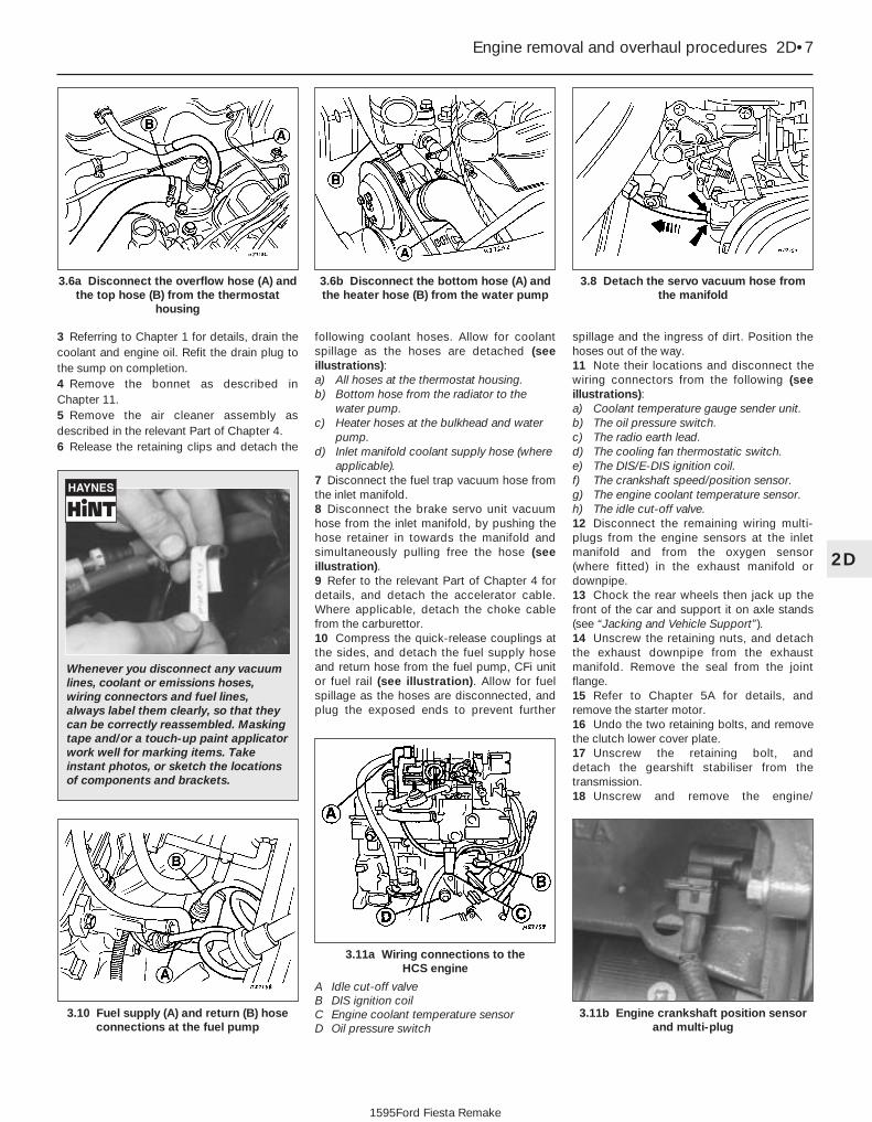
3 Referring to Chapter 1 for details, drain thecoolant and engine oil. Refit the drain plug tothe sump on completion.4 Remove the bonnet as described inChapter 11.5 Remove the air cleaner assembly asdescribed in the relevant Part of Chapter 4.6 Release the retaining clips and detach the
following coolant hoses. Allow for coolantspillage as the hoses are detached (seeillustrations):a) All hoses at the thermostat housing.b) Bottom hose from the radiator to the
water pump.c) Heater hoses at the bulkhead and water
pump.d) Inlet manifold coolant supply hose (where
applicable).7 Disconnect the fuel trap vacuum hose fromthe inlet manifold.8 Disconnect the brake servo unit vacuumhose from the inlet manifold, by pushing thehose retainer in towards the manifold andsimultaneously pulling free the hose (seeillustration).9 Refer to the relevant Part of Chapter 4 fordetails, and detach the accelerator cable.Where applicable, detach the choke cablefrom the carburettor.10 Compress the quick-release couplings atthe sides, and detach the fuel supply hoseand return hose from the fuel pump, CFi unitor fuel rail (see illustration). Allow for fuelspillage as the hoses are disconnected, andplug the exposed ends to prevent further
spillage and the ingress of dirt. Position thehoses out of the way.11 Note their locations and disconnect thewiring connectors from the following (seeillustrations):a) Coolant temperature gauge sender unit.b) The oil pressure switch.c) The radio earth lead.d) The cooling fan thermostatic switch.e) The DIS/E-DIS ignition coil.f) The crankshaft speed/position sensor.g) The engine coolant temperature sensor.h) The idle cut-off valve.12 Disconnect the remaining wiring multi-plugs from the engine sensors at the inletmanifold and from the oxygen sensor (where fitted) in the exhaust manifold ordownpipe.13 Chock the rear wheels then jack up thefront of the car and support it on axle stands(see “Jacking and Vehicle Support”).14 Unscrew the retaining nuts, and detachthe exhaust downpipe from the exhaustmanifold. Remove the seal from the jointflange.15 Refer to Chapter 5A for details, andremove the starter motor.16 Undo the two retaining bolts, and removethe clutch lower cover plate.17 Unscrew the retaining bolt, and detach the gearshift stabiliser from thetransmission.18 Unscrew and remove the engine/
Engine removal and overhaul procedures 2D•7
3.8 Detach the servo vacuum hose fromthe manifold
3.6b Disconnect the bottom hose (A) andthe heater hose (B) from the water pump
3.6a Disconnect the overflow hose (A) andthe top hose (B) from the thermostat
housing
3.11b Engine crankshaft position sensorand multi-plug
3.11a Wiring connections to the HCS engine
A Idle cut-off valveB DIS ignition coilC Engine coolant temperature sensorD Oil pressure switch
3.10 Fuel supply (A) and return (B) hoseconnections at the fuel pump
2D
1595Ford Fiesta Remake
Whenever you disconnect any vacuumlines, coolant or emissions hoses,wiring connectors and fuel lines,always label them clearly, so that theycan be correctly reassembled. Maskingtape and/or a touch-up paint applicatorwork well for marking items. Takeinstant photos, or sketch the locationsof components and brackets.

transmission flange attachment bolts (seeillustration).19 Check that the appropriate undersideattachments are disconnected and out of theway, then lower the vehicle to the ground.20 Unbolt and remove the heat shield fromthe exhaust manifold.21 Attach a suitable hoist to the engine. It ispossible to fabricate lifting eyes to connectthe hoist to the engine, but make sure thatthey are strong enough, and connect them tothe inlet and exhaust manifold at diagonally-opposite ends of the engine.22 With the hoist securely connected, takethe weight of the engine. Unscrew andremove the right-hand engine mounting sidebolt from under the right-hand wheel arch.Unscrew and remove the mounting retainingnut and washer from the suspension strut cupretaining plate, and the three bolts securingthe mounting unit to the cylinder block.23 Locate a jack under the transmission, andraise it to take the weight of the transmission.24 Unscrew and remove the remainingengine-to-transmission retaining bolts on theupper flange.25 Check around the engine to ensure that allof the relevant fixings and attachments aredisconnected and out of the way for theremoval.26 Enlist the aid of an assistant, then movethe engine sideways and away from thetransmission, whilst simultaneously raising the transmission. When the engine isseparated from the transmission, carefullyguide it up and out of the enginecompartment. Do not allow the weight of theengine to hang on the transmission input shaftat any point during the removal (or refitting) ofthe engine. When the engine sump is clear of the vehicle, swing the power unit out of theway, and lower it onto a trolley (if available).Unless a mobile hoist is being used, it will benecessary to move the vehicle rearwards andout of the way in order to allow the engine tobe lowered for removal. In this instance,ensure that the weight of the transmission iswell supported as the vehicle is moved.27 While the engine is removed, check themountings; renew them if they are worn ordamaged. Similarly, check the condition of allcoolant and vacuum hoses and pipes (see
Chapter 1); components that are normallyhidden can now be checked properly, andshould be renewed if there is any doubt at allabout their condition. Also, take theopportunity to overhaul the clutchcomponents (see Chapter 6). It is regarded bymany as good working practice to renew theclutch assembly as a matter of course,whenever major engine overhaul work iscarried out. Check also the condition of allcomponents disturbed on removal, and renewany that are damaged or worn.
Refitting28 Refitting is in general, a reversal of theremoval procedure, but the following specialpoints should be noted.29 Before coupling the engine to thetransmission, apply a thin smear of high-melting-point grease onto the transmissioninput shaft splines. If the clutch has beenremoved, ensure that the clutch disc iscentralised, and disconnect the clutch cablefrom the release lever on the transmissioncasing.30 Tighten all fixings to their recommendedtorque wrench settings.31 Check that the mating faces are clean,and fit a new exhaust downpipe-to-manifoldgasket and self-locking nuts whenreconnecting this joint.32 Ensure that all wiring connections arecorrectly and securely made.33 Remove the plugs from the fuel linesbefore reconnecting them correctly andsecurely.34 Reconnect and adjust the accelerator andchoke cables as described in the relevant Partof Chapter 4. The refitting details for the aircleaner components are also given in thatChapter.35 Renew any coolant hoses (and/orretaining clips) that are not in good condition.36 Refer to Chapter 6 for details onreconnecting the clutch cable.37 When the engine is fully refitted, checkthat the various hoses are connected, andthen top-up the engine oil and coolant levelsas described in Chapter 1 and “WeeklyChecks”.38 When engine refitting is completed, refer toSection 19 for the engine start-up procedures.
4 Engine/transmission -removal and refitting (CVH andPTE engines)
3Warning: Petrol is extremelyflammable, so take extraprecautions when disconnectingany part of the fuel system.
Don’t smoke, or allow naked flames or barelight bulbs, in or near the work area, anddon’t work in a garage where a natural-gasappliance (such as a clothes dryer or waterheater) is installed. If you spill petrol onyour skin, rinse it off immediately. Have afire extinguisher rated for petrol fireshandy, and know how to use it.Note: Read through the entire Section, as wellas reading the advice in Section 2, beforebeginning this procedure. The engine andtransmission are removed as a unit, lowered tothe ground and removed from underneath,then separated outside the vehicle.
Removal1 On all fuel injection engines, refer toChapter 4B, C or D as applicable anddepressurise the fuel system.2 Disconnect the battery negative (earth) lead(refer to Chapter 5A, Section 1).3 Referring to Chapter 1 for details, drain thecoolant and the engine oil. Refit the drain plugto the sump on completion.4 Refer to Chapter 11 for details, and removethe bonnet.5 Remove the air cleaner assembly and airinlet components as described in the relevantPart of Chapter 4.6 Release the retaining clips and detach thecoolant top hose, the heater hose and theradiator overflow hose from the thermostathousing. Disconnect the coolant hose fromthe inlet manifold, and the bottom hose fromthe water pump and/or the radiator (seeillustrations). On 1.4 litre CFi fuel injectionmodels, also disconnect the coolant hosefrom the injection unit. On EFi and SEFi fuelinjection models, detach the heater hose Y-connector. Allow for coolant spillage as thehoses are detached. On turbochargedengines, disconnect the coolant return hosefrom the turbocharger connecting pipe.
2D•8 Engine removal and overhaul procedures
4.6b Heater coolant hoses and Y-connectoron 1.6 litre EFi fuel injection models
4.6a Coolant hose connections to thethermostat (arrowed)
3.18 Engine-to-transmission flangeattachment bolts (arrowed)
1595Ford Fiesta Remake

7 Refer to the relevant Part of Chapter 4 fordetails, and disconnect the accelerator cablefrom the throttle linkage and support/adjusterbracket. Where applicable, also disconnectthe choke cable. Position the cable(s) out ofthe way.8 On carburettor models, disconnect the fuelsupply hose from the fuel pump, and thereturn hose from the carburettor.9 On CFi models, detach the fuel hose at theinjector/pressure regulator unit, and the returnline, by compressing the couplings whilstpulling the hoses free from their connections.On EFi and SEFi models, unscrew the unionnut to detach the fuel line from the fuel rail;release the retaining clip to detach the returnpipe from the pressure regulator. Plug theexposed ends of the hoses and connections,to prevent fuel spillage and the ingress of dirt.Position the hoses out of the way.10 Press the clamp ring inwards, andsimultaneously pull free the brake servo hose
from the inlet manifold. Position it out of theway.11 On CFi and EFi models, detach thevacuum hose from the MAP sensor, and thehose between the carbon canister and the fuelinjection unit (see illustration).12 Note their connections and routings, anddetach the following wiring connections,according to model (see illustrations):a) Coolant temperature sender unit.b) Oil pressure switch.c) E-DIS ignition coil unit. or distributor.d) Coolant temperature sensor.e) Cooling fan thermostatic switch.f) Carburettor.g) Earth lead (radio).h) Reversing light switch (from transmission).i) Crankshaft position sensor.j) Earth leads from the transmission and
engine.13 Disconnect the wiring at the followingadditional items specific to fuel injectionmodels only.a) Inlet air temperature sensor.b) Vehicle speed sensor.c) Throttle plate control motor (CFi
models).d) Throttle position sensor.e) Injector harness connector.f) Idle speed control valve (EFi and SEFi
models).14 Unscrew the retaining bolt and detach thebracket locating the wiring and coolant hosesabove the transmission.
15 Disconnect the speedometer drive cablefrom the transmission.16 On manual transmission models,disconnect the clutch cable from the releaselever at the transmission (see Chapter 6 fordetails). Position the cable out of the way.17 On vehicles fitted with the anti-lockbraking system, refer to Chapter 9 and releasethe left-hand modulator from its mountingbracket, without disconnecting the rigid brakepipes or return hose. Tie the modulatorsecurely to the bulkhead.18 Chock the rear wheels then jack up thefront of the car and support it on axle stands(see “Jacking and Vehicle Support”). Allowsufficient clearance under the vehicle towithdraw the engine and transmission unitsfrom under the front end.19 On XR2i models, refer to Chapter 10 andremove the front suspension crossmember.20 Where applicable on catalytic converter-equipped vehicles, release the multi-plug fromthe bracket and disconnect the wiringconnector from the oxygen sensor in theexhaust downpipe.21 Undo the three retaining bolts, detach theexhaust downpipe from the manifold, andcollect the gasket from the flange joint. Nowdisconnect the exhaust downpipe from therest of the system, and remove it from thevehicle.22 Where fitted, undo the four retaining nutsand two bolts securing the front part of theexhaust heat shield to the floor, then removethe heat shield.23 Refer to Chapter 5A and remove thealternator and starter motor. On models withpower steering, refer to Chapter 10 andremove the power steering pump.
Manual transmission models24 On 4-speed models, select 2nd gear; on5-speed models, select 4th gear, to assist incorrect adjustment of the gearchange duringreassembly. If it is likely that the gear lever willbe moved from this position before refitting,mark the relative position of the transmissionshift rod and the selector shaft beforeseparating them. Undo the clamp bolt, andthen pull free and detach the shift rod from theselector shaft (see illustration).
Engine removal and overhaul procedures 2D•9
4.12b . . . the oil pressure switch . . .4.12a Disconnect the wiring at thetemperature gauge sender unit . . .
4.11 Vacuum hose to MAP sensor (A) andbrake servo (B)
4.24 Manual transmission shift rod clampbolt (A), stabiliser-to-transmission bolt (B)
and washer (C)4.12c . . . and the crankshaft position
sensor
2D
1595Ford Fiesta Remake
Whenever you disconnectany vacuum lines, coolant oremissions hoses, wiringconnectors and fuel lines,
always label them clearly, so that theycan be correctly reassembled. Maskingtape and/or a touch-up paint applicatorwork well for marking items. Takeinstant photos, or sketch the locationsof components and brackets.

25 Unscrew the retaining bolt, and detachthe shift rod stabiliser from the transmission.As it is detached, note the washer locatedbetween the stabiliser and the transmission.Tie the stabiliser and the shift rod up out ofthe way.
Automatic transmission models26 Unclip and detach the wiring connectorfrom the starter inhibitor switch (on thetransmission housing).27 Referring to the relevant Part of Chapter 4for details, unhook the accelerator (cam plate)cable from the carburettor or fuel injection unit(as applicable) at the transmission end of the cable. Undo the retaining bolt and detach the cable sheath bracket from thetransmission. Detach the cam plate cablefrom the link.28 Undo the two nuts from the selector cablebracket which connects it to the lever on theselector shaft. Disconnect the yoke from thelever on the selector shaft and the cable fromthe lever.29 Unscrew the union nuts, and disconnectthe oil cooler feed and return pipes from thetransmission. Allow for a certain amount ofspillage, and plug the connections to preventthe ingress of dirt.
All models30 Unscrew the retaining nut and withdrawthe Torx-type clamp bolt securing the lowersuspension arm to the spindle carrier on eachside.31 Refer to Chapter 10 for details, anddetach the right-hand and left-hand track rodend balljoints from the spindle carriers.32 On vehicles fitted with the anti-lockbraking system, refer to Chapter 9 and releasethe right-hand modulator from its mountingbracket without disconnecting the rigid brakepipes or return hose. Tie the modulatorsecurely to the bulkhead. Additionally, undothe three bolts securing the modulatorbracket.33 Insert a suitable lever between the right-hand driveshaft inner joint and thetransmission housing, and prise free thedriveshaft from the transmission; be preparedfor oil spillage from the transmission casethrough the vacated driveshaft aperture. As itis being prised free, simultaneously pull theroadwheel outwards on that side, to enablethe driveshaft inboard end to separate from the transmission. Once it is free,suspend and support the driveshaft from thesteering gear, to prevent unnecessary strainbeing placed on the driveshaft joints.34 Insert a suitable plastic plug (or ifavailable, an old driveshaft joint), into thetransmission driveshaft aperture, toimmobilise the gears of the differential unit.35 Proceed as described above inparagraphs 33 and 34, and disconnect theleft-hand driveshaft from the transmission.36 Connect a suitable lift hoist and sling tothe engine, connecting to the lifting eyes.
When securely connected, take the weight ofthe engine/transmission unit so that thetension is relieved from the mountings.37 Undo the retaining bolts and nuts anddetach the right-hand engine mounting fromthe vehicle body.38 Undo the four bolts securing thetransmission bearer to the underside of thevehicle body. The transmission bearer isremoved with the engine/transmissionassembly.39 Unscrew the three retaining bolts, andremove the auxiliary drivebelt cover fromunder the crankshaft pulley.40 The engine/transmission unit should nowbe ready for removal from the vehicle. Checkthat all of the associated connections andfittings are disconnected from the engine andtransmission, and positioned out of the way.41 Enlist the aid of an assistant to helpsteady and guide the power unit downthrough the engine compartment as it isremoved. If available, position a suitableengine trolley or crawler board under theengine/transmission so that when lowered,the power unit can be withdrawn from thefront end of the vehicle, and then moved tothe area where it is to be cleaned anddismantled. On automatic transmissionmodels, particular care must be taken not todamage the transmission fluid pan (sump)during the removal and subsequent refittingprocesses.42 Carefully lower the engine andtransmission unit, ensuring that no fittingsbecome snagged. Detach the hoist andremove the power unit from under the vehicle.43 Referring to the relevant Part of Chapter 7,separate the transmission from the engine.44 While the engine/transmission is removed,check the mountings; renew them if they areworn or damaged. Similarly, check thecondition of all coolant and vacuum hosesand pipes (see Chapter 1). Components thatare normally hidden can now be checkedproperly, and should be renewed if there isany doubt at all about their condition. Wherethe vehicle is fitted with manual transmission,take the opportunity to inspect the clutchcomponents (see Chapter 6). It is regarded bymany as good working practice to renew theclutch assembly as a matter of course,whenever major engine overhaul work iscarried out. Check also the condition of allcomponents (such as the transmission oilseals) disturbed on removal, and renew anythat are damaged or worn.
Refitting45 Refitting is a reversal of removal, howevernote the following additional points:a) Refer to the applicable Chapters and
Sections as for removal.b) Fit new spring clips to the grooves in the
inboard end of the right- and left-handdriveshaft joints. Lubricate the splineswith transmission oil prior to fitting.
c) Renew the exhaust flange gasket whenreconnecting the exhaust. Ensure that allwires are routed clear of the exhaustsystem and, on catalytic convertermodels, ensure that the heat shields aresecurely and correctly fitted.
d) Ensure that all earth lead connections areclean and securely made.
e) Tighten all nuts and bolts to the specifiedtorque.
f) Fit a new oil filter, and refill the engine andtransmission with oil, with reference toChapter 1.
g) Refill the cooling system with reference toChapter 1.
h) Refit the alternator and starter motor withreference to Chapter 5A.
i) Where applicable, refit the power steeringpump with reference to Chapter 10.
46 When engine and transmission refitting iscomplete, refer to the procedures describedin Section 19 before restarting the engine.
5 Engine/transmission -removal and refitting (Zetec engines)
3Warning: Petrol is extremelyflammable, so take extraprecautions when disconnectingany part of the fuel system.
Don’t smoke, or allow naked flames orbare light bulbs, in or near the work area,and don’t work in a garage where anatural-gas appliance (such as a clothesdryer or water heater) is installed. If youspill petrol on your skin, rinse it offimmediately. Have a fire extinguisher ratedfor petrol fires handy, and know how touse it.Note: Read through the entire Section, as wellas reading the advice in Section 2, beforebeginning this procedure. The engine andtransmission are removed as a unit, lowered tothe ground and removed from underneath,then separated outside the vehicle.
Removal1 Park the vehicle on firm, level ground, applythe handbrake firmly, and slacken the nutssecuring both front roadwheels.2 Depressurise the fuel system as describedin Chapter 4D.3 Disconnect the battery negative (earth) lead(refer to Chapter 5A, Section 1).4 Place protective covers on the wings, thenremove the bonnet (see Chapter 11).5 Drain the cooling system and the engine oil(see Chapter 1).6 Remove the air inlet components and thecomplete air cleaner assembly as described inChapter 4D.7 Equalise the pressure in the fuel tank byremoving the filler cap, then release the fuelfeed and return quick-release couplings, andpull the hoses off the fuel pipes. Plug or capall open fittings.
2D•10 Engine removal and overhaul procedures
1595Ford Fiesta Remake

8 Disconnect the accelerator cable from thethrottle linkage as described in Chapter 4D.Secure the cable clear of theengine/transmission.9 Releasing its wire clip, unplug the wiringconnector from the power steering pressureswitch (where fitted), then disconnect theearth cable from the engine lifting eye. Refitthe bolt after disconnecting the cable.10 Marking or labelling all components asthey are disconnected, disconnect thevacuum hoses as follows:a) From the rear of the inlet manifold.b) The braking system vacuum servo unit
hose - from the inlet manifold (seeChapter 9 for details).
c) While you are there, trace the vacuum linefrom the pulse-air filter housing, anddisconnect it from the pulse-air solenoidvalve.
d) Secure all these hoses so that they won’tget damaged as the engine/transmissionis removed.
11 Unbolt the engine/transmission-to-body
earth lead from the transmission (seeillustration). Disconnect the speedometerdrive cable (see Chapter 12) and secure itclear of the engine/transmission.12 Disconnect the earth strap at the top ofthe engine/transmission flange, and theadjacent bolt securing the wiring harness clip.13 Where the vehicle is fitted with manualtransmission, disconnect the clutch cable (seeChapter 6).14 Marking or labelling all components asthey are disconnected, disconnect the enginewiring connectors as follows (seeillustrations):a) The multi-plug from the E-DIS ignition
coil.b) The radio interference suppressor from
the DIS ignition coil.c) The reversing light switch multi-plug.d) The engine main wiring loom multi-plug
behind the E-DIS ignition coil.e) The crankshaft speed/position sensor and
vehicle speed sensor multi-plugs.f) The oxygen sensor multi-plug.15 Unbolt the exhaust manifold heat shield,and lift it clear.16 Remove the auxiliary drivebelt (seeChapter 1).17 Marking or labelling all components asthey are disconnected and catching as muchas possible of the escaping coolant in thedrain tray, disconnect the cooling systemhoses and pipes as follows:a) The coolant hoses at the thermostat
housing.
b) The coolant hose at the metal cross pipelower connection.
c) The radiator top and bottom hoses.18 Where applicable, detach the powersteering pump pressure pipe clips, release theunions and disconnect the pump pressureand return lines. Collect the fluid in a suitable container, and plug the disconnectedunions.19 On vehicles fitted with the anti-lockbraking system, refer to Chapter 9 and releasethe left-hand modulator from its mountingbracket, without disconnecting the rigid brakepipes or return hose. Tie the modulatorsecurely to the bulkhead.20 Chock the rear wheels then jack up thefront of the car and support it on axle stands(see “Jacking and Vehicle Support”). Removethe front roadwheels.21 Refer to Chapter 5 if necessary, anddisconnect the wiring from the starter motorand alternator.22 Disconnect the oil pressure switch wiringconnector.23 On automatic transmission models,disconnect the starter inhibitor switch wiringand disconnect the selector cable (seeChapter 7B). Secure the cable clear of theengine/transmission.24 Where the vehicle is fitted with manualtransmission, disconnect the gearchangelinkage and transmission support rod from therear of the transmission - make alignmentmarks as they are disconnected (seeillustrations).
Engine removal and overhaul procedures 2D•11
5.14b . . . the radio interferencesuppressor . . .
5.14a Disconnect the wiring multi-plugfrom the ignition coil . . .
5.11 Unbolt the engine/transmission-to-body earth lead from the transmission
5.24b . . . and transmission support rod5.24a Disconnect the gearchange linkage . . .5.14c . . . and the reversing light switch
2D
1595Ford Fiesta Remake
Whenever you disconnectany vacuum lines, coolant oremissions hoses, wiringconnectors and fuel lines,
always label them clearly, so that theycan be correctly reassembled. Maskingtape and/or a touch-up paint applicatorwork well for marking items. Takeinstant photos, or sketch the locationsof components and brackets.

25 On automatic transmission models, cleanaround the unions, then disconnect the fluidpipes from the transmission. Plug theopenings in the transmission and the pipeunions after removal.26 Refer to Chapter 10 and remove the frontsuspension crossmember.27 Unscrew the nuts to disconnect theexhaust system front downpipe from themanifold. Undo the nuts securing the catalyticconverter to the rear part of the exhaustsystem, and remove the converter anddownpipe assembly.28 On vehicles fitted with the anti-lock brakingsystem, refer to Chapter 9 and release theright-hand modulator from its mountingbracket without disconnecting the rigid brakepipes or return hose. Tie the modulatorsecurely to the bulkhead. Additionally, undothe three bolts securing the modulator bracket.29 Disconnect both anti-roll bar links fromtheir respective suspension struts, and bothtrack rod end ball joints from their spindlecarriers (see Chapter 10).30 Unscrew the retaining nut and withdrawthe Torx-type clamp bolt securing the lowersuspension arm to the spindle carrier on eachside.31 Insert a suitable lever between the right-hand driveshaft inner joint and thetransmission housing, and prise free thedriveshaft from the transmission; be preparedfor oil spillage from the transmission casethrough the vacated driveshaft aperture. As itis being prised free, simultaneously pull theroadwheel outwards on that side to enable thedriveshaft inboard end to separate from thetransmission. Once it is free, suspend andsupport the driveshaft from the steering gear,to prevent unnecessary strain being placed onthe driveshaft joints.32 Insert a suitable plastic plug (or ifavailable, an old driveshaft joint), into thetransmission driveshaft aperture, toimmobilise the gears of the differential unit.33 Proceed as described above inparagraphs 31 and 32, and disconnect theleft-hand driveshaft from the transmission.34 Remove the oil filter, referring to Chapter 1if necessary.35 Connect a suitable lift hoist and sling tothe engine, connecting to the lift eyes. Whensecurely connected, take the weight of theengine/transmission unit so that the tension isrelieved from the mountings.36 Unbolt the engine rear right-handmounting from the body (one bolt in the wheelarch, one nut in the engine compartment),then unbolt the engine front right-handmounting from the alternator mountingbracket. Unbolt the transmission bearer fromthe underbody.37 The engine/transmission unit should nowbe hanging on the hoist only, with allcomponents which connect it to the rest ofthe vehicle disconnected or removed, andsecured well clear of the unit. Make a finalcheck that this is the case.
38 Lower the engine/transmission to theground, and withdraw it from under thevehicle.39 Referring to the relevant Part of Chapter 7,separate the transmission from the engine.40 While the engine/transmission is removed,check the mountings; renew them if they areworn or damaged. Similarly, check thecondition of all coolant and vacuum hosesand pipes (see Chapter 1); components thatare normally hidden can now be checkedproperly, and should be renewed if there isany doubt at all about their condition. Wherethe vehicle is fitted with manual transmission,take the opportunity to overhaul the clutchcomponents (see Chapter 6). It is regarded bymany as good working practice to renew theclutch assembly as a matter of course,whenever major engine overhaul work iscarried out. Check also the condition of allcomponents (such as the transmission oilseals) disturbed on removal, and renew anythat are damaged or worn.
Refitting41 Refitting is a reversal of removal, howevernote the following additional points:a) Refer to the applicable Chapters and
Sections as for removal.b) Fit new spring clips to the grooves in the
inboard end of the right- and left-handdriveshaft joints. Lubricate the splineswith transmission oil prior to fitting.
c) Renew the exhaust flange gaskets whenreconnecting the exhaust. Ensure that allwires are routed clear of the exhaustsystem, and that the heat shields aresecurely and correctly fitted.
d) Ensure that all earth lead connections areclean and securely made.
e) Tighten all nuts and bolts to the specifiedtorque.
f) Fit a new oil filter, and refill the engine andtransmission with oil, with reference toChapter 1.
g) Refill the cooling system with reference toChapter 1.
h) Bleed the power steering system withreference to Chapter 10.
42 When engine and transmission refitting iscomplete, refer to the procedures describedin Section 19 before restarting the engine.
6 Engine overhaul -preliminary information
It is much easier to dismantle and work onthe engine if it is mounted on a portableengine stand. These stands can often be hiredfrom a tool hire shop. Before the engine ismounted on a stand, the flywheel/driveplateshould be removed so that the stand boltscan be tightened into the end of the cylinderblock/crankcase.
If a stand is not available, it is possible todismantle the engine with it suitably
supported on a sturdy, workbench or on thefloor. Be careful not to tip or drop the enginewhen working without a stand.
If you intend to obtain a reconditionedengine, all ancillaries must be removed first, tobe transferred to the replacement engine (justas they will if you are doing a complete engineoverhaul yourself). These components includethe following:a) Alternator/power steering pump and
mounting brackets.b) DIS/E-DIS ignition coil unit (and mounting
bracket), distributor, HT leads and sparkplugs.
c) The thermostat and housing cover.d) Carburettor/fuel injection system
components.e) Inlet and exhaust manifolds.f) Oil filter.g) Fuel pump.h) Engine mountings.i) Flywheel/driveplate.j) Water pump.Note: When removing the externalcomponents from the engine, pay closeattention to details that may be helpful orimportant during refitting. Note the fittedpositions of gaskets, seals, washers, bolts andother small items.
If you are obtaining a “short” engine(cylinder block/crankcase, crankshaft, pistonsand connecting rods all assembled), then thecylinder head, timing chain/belt (together withtensioner, tensioner and idler pulleys andcovers) sump and oil pump will have to beremoved also.
If a complete overhaul is planned, theengine can be dismantled in the order givenbelow, referring to Part A, B or C of thisChapter unless otherwise stated.a) Inlet and exhaust manifolds.b) Timing chain/belt, tensioner and
sprockets.c) Cylinder head.d) Flywheel/driveplate.e) Sump.f) Oil pump.g) Pistons (with connecting rods).h) Crankshaft.i) Camshaft and tappets (HCS engines).
7 Cylinder head - dismantling 4Note: New and reconditioned cylinder headsare available from the manufacturers, and fromengine overhaul specialists. Due to the factthat some specialist tools are required for thedismantling and inspection procedures, andnew components may not be readily available,it may be more practical and economical forthe home mechanic to purchase areconditioned head, rather than to dismantle,inspect and recondition the original head.1 Remove the cylinder head as described inPart A, B or C of this Chapter (as applicable).
2D•12 Engine removal and overhaul procedures
1595Ford Fiesta Remake

2 If not already done, remove the inlet andexhaust manifolds with reference to therelevant Part of Chapter 4.3 Proceed as follows according to enginetype.
HCS engines4 Valve removal should commence with No 1valve (nearest the timing chain end).5 To remove the valve springs and valvesfrom the cylinder head, a standard valvespring compressor will required. Fit the springcompressor to the first valve and spring to beremoved. Take care not to damage the valvestem with the compressor, and do not over-compress the spring, or the valve stem maybend. When tightening the compressor, it maybe found that the spring retainer does notrelease and the collets are then difficult toremove. In this instance, remove thecompressor, then press a piece of tube (or asocket of suitable diameter) so that it does notinterfere with the removal of the collets,against the retainer’s outer rim. Tap the tube(or socket) with a hammer to unsettle thecomponents.6 Refit the compressor, and wind it in toenable the collets to be extracted (seeillustration).7 Loosen off the compressor, and remove theretainer and spring. Withdraw the valve fromthe cylinder head (see illustrations).8 Prise up and remove the valve stem seal.9 Repeat the removal procedure with each of
the remaining seven valve assemblies in turn.As they are removed, keep the individualvalves and their components together, and intheir respective order of fitting, by placingthem in a separate labelled bag (seeillustration).
CVH and PTE engines10 Remove the camshaft, rocker arms andtappets as described in Part B of this Chapter,being careful to store the hydraulic tappets asdescribed.11 Valve removal should commence with No 1 valve (nearest the timing belt end).12 Using a standard valve spring com-pressor, compress the valve spring (andupper retainer) just enough to enable the splitcollets to be released from the groove in thetop of the valve stem, then separate andextract the split collets from the valve. Do notcompress the spring any further than isnecessary, or the valve stem may bend. If thevalve spring retainer does not release from thecollets as the spring is compressed, removethe compressor, and position a piece ofsuitable tube over the end of the retainer, sothat it does not impinge on the collets. Place asmall block of wood under the valve head(with the head resting face down on theworkbench), then tap the end of the tube witha hammer. Now refit the compressor tool, andcompress the valve spring. The collets shouldrelease.13 Extract the split collets, then slowly
unscrew, release and remove the compressor.14 Withdraw the upper retainer and the valvespring from the valve stem, then remove thevalve from the underside of the cylinder head.Use a suitable screwdriver or pliers to prisefree and remove the valve stem oil seal fromthe guide (see illustration).15 Remove the lower retainer.16 Repeat the removal procedure with eachof the remaining valve assemblies in turn. Asthey are removed, keep the valves and theirassociated components together, and in theoriginally-installed order, by placing them in aseparate labelled bag (see illustration 7.9).
Zetec engines17 Remove the camshafts and hydraulictappets as described in Part C of this Chapter,being careful to store the hydraulic tappets asdescribed.18 Using a valve spring compressor,compress each valve spring in turn until thesplit collets can be removed. A special valvespring compressor will be required, to reachinto the deep wells in the cylinder headwithout risk of damaging the hydraulic tappetbores; such compressors are now widelyavailable from most good motor accessoryshops. Release the compressor, and lift offthe spring upper seat and spring.19 If, when the valve spring compressor isscrewed down, the spring upper seat refusesto free and expose the split collets, gently tapthe top of the tool, directly over the upperseat, with a light hammer. This will free theseat.20 Withdraw the valve through thecombustion chamber. If it binds in the guide(won’t pull through), push it back in, and de-burr the area around the collet groove with afine file or whetstone; take care not to markthe hydraulic tappet bores.21 Ford recommend the use of their servicetool 21-160 to extract the valve spring lowerseat/stem oil seals; while this is almostindispensable if the seals are to be removedwithout risk of damage to the cylinder head, aserviceable substitute can be made from astrong spring of suitable size. Screw on thetool or spring so that it bites into the seal, then
Engine removal and overhaul procedures 2D•13
7.7b . . . followed by the valve7.7a Remove the valve spring retainer andspring . . .
7.6 Compress the valve spring to removethe collets
7.14 Prise off the valve stem oil seal7.9 Use a labelled plastic bag to store andidentify valve components
2D
1595Ford Fiesta Remake
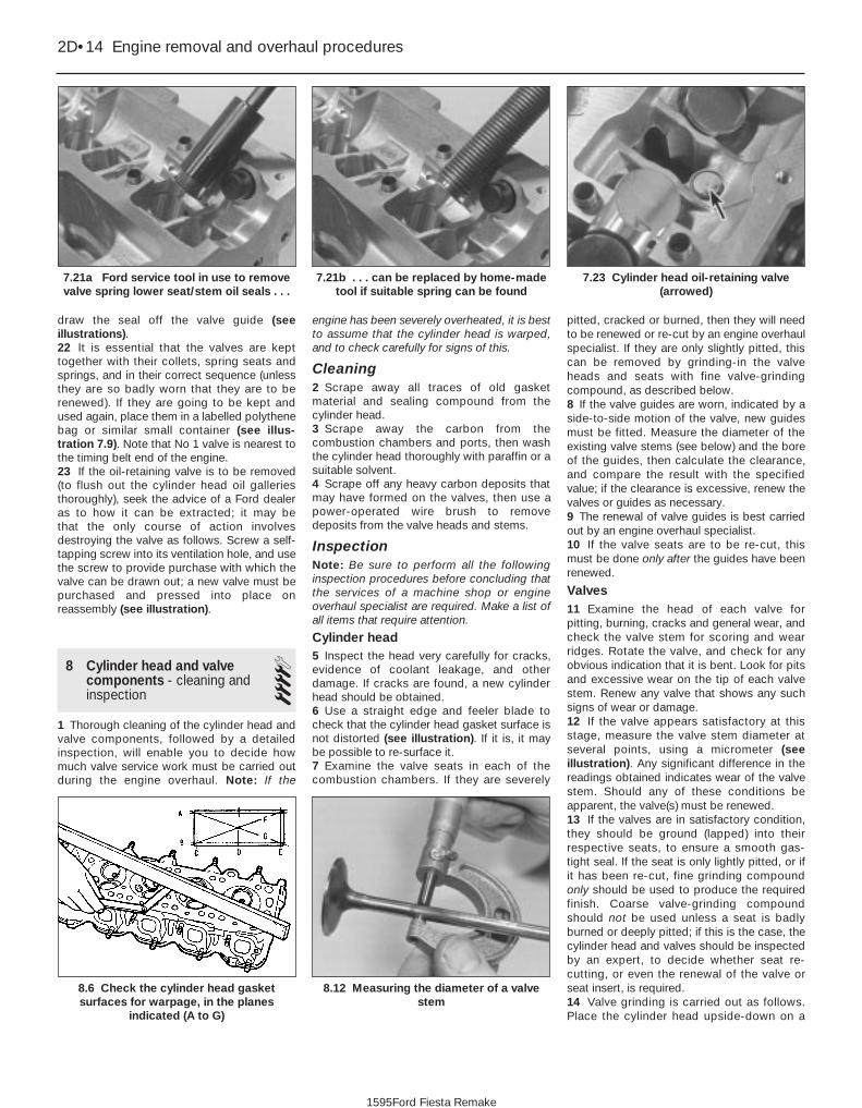
draw the seal off the valve guide (seeillustrations).22 It is essential that the valves are kepttogether with their collets, spring seats andsprings, and in their correct sequence (unlessthey are so badly worn that they are to berenewed). If they are going to be kept andused again, place them in a labelled polythenebag or similar small container (see illus-tration 7.9). Note that No 1 valve is nearest tothe timing belt end of the engine.23 If the oil-retaining valve is to be removed(to flush out the cylinder head oil galleriesthoroughly), seek the advice of a Ford dealeras to how it can be extracted; it may be that the only course of action involvesdestroying the valve as follows. Screw a self-tapping screw into its ventilation hole, and use the screw to provide purchase with which thevalve can be drawn out; a new valve must bepurchased and pressed into place onreassembly (see illustration).
8 Cylinder head and valvecomponents - cleaning andinspection
41 Thorough cleaning of the cylinder head andvalve components, followed by a detailedinspection, will enable you to decide howmuch valve service work must be carried outduring the engine overhaul. Note: If the
engine has been severely overheated, it is bestto assume that the cylinder head is warped,and to check carefully for signs of this.
Cleaning2 Scrape away all traces of old gasketmaterial and sealing compound from thecylinder head.3 Scrape away the carbon from thecombustion chambers and ports, then washthe cylinder head thoroughly with paraffin or asuitable solvent.4 Scrape off any heavy carbon deposits thatmay have formed on the valves, then use apower-operated wire brush to removedeposits from the valve heads and stems.
InspectionNote: Be sure to perform all the followinginspection procedures before concluding thatthe services of a machine shop or engineoverhaul specialist are required. Make a list ofall items that require attention.
Cylinder head5 Inspect the head very carefully for cracks,evidence of coolant leakage, and otherdamage. If cracks are found, a new cylinderhead should be obtained.6 Use a straight edge and feeler blade tocheck that the cylinder head gasket surface isnot distorted (see illustration). If it is, it maybe possible to re-surface it.7 Examine the valve seats in each of thecombustion chambers. If they are severely
pitted, cracked or burned, then they will needto be renewed or re-cut by an engine overhaulspecialist. If they are only slightly pitted, thiscan be removed by grinding-in the valveheads and seats with fine valve-grindingcompound, as described below.8 If the valve guides are worn, indicated by aside-to-side motion of the valve, new guidesmust be fitted. Measure the diameter of theexisting valve stems (see below) and the boreof the guides, then calculate the clearance,and compare the result with the specifiedvalue; if the clearance is excessive, renew thevalves or guides as necessary.9 The renewal of valve guides is best carriedout by an engine overhaul specialist.10 If the valve seats are to be re-cut, thismust be done only after the guides have beenrenewed.
Valves11 Examine the head of each valve forpitting, burning, cracks and general wear, andcheck the valve stem for scoring and wearridges. Rotate the valve, and check for anyobvious indication that it is bent. Look for pitsand excessive wear on the tip of each valvestem. Renew any valve that shows any suchsigns of wear or damage.12 If the valve appears satisfactory at thisstage, measure the valve stem diameter atseveral points, using a micrometer (seeillustration). Any significant difference in thereadings obtained indicates wear of the valvestem. Should any of these conditions beapparent, the valve(s) must be renewed.13 If the valves are in satisfactory condition,they should be ground (lapped) into theirrespective seats, to ensure a smooth gas-tight seal. If the seat is only lightly pitted, or ifit has been re-cut, fine grinding compoundonly should be used to produce the requiredfinish. Coarse valve-grinding compoundshould not be used unless a seat is badlyburned or deeply pitted; if this is the case, thecylinder head and valves should be inspectedby an expert, to decide whether seat re-cutting, or even the renewal of the valve orseat insert, is required.14 Valve grinding is carried out as follows.Place the cylinder head upside-down on a
2D•14 Engine removal and overhaul procedures
8.12 Measuring the diameter of a valvestem
8.6 Check the cylinder head gasketsurfaces for warpage, in the planes
indicated (A to G)
7.23 Cylinder head oil-retaining valve(arrowed)
7.21b . . . can be replaced by home-madetool if suitable spring can be found
7.21a Ford service tool in use to removevalve spring lower seat/stem oil seals . . .
1595Ford Fiesta Remake

bench, with a block of wood at each end togive clearance for the valve stems.15 Smear a trace of (the appropriate gradeof) valve-grinding compound on the seat face,and press a suction grinding tool onto thevalve head. With a semi-rotary action, grindthe valve head to its seat, lifting the valveoccasionally to redistribute the grindingcompound (see illustration). A light springplaced under the valve head will greatly easethis operation.16 If coarse grinding compound is beingused, work only until a dull, matt even surfaceis produced on both the valve seat and thevalve, then wipe off the used compound, andrepeat the process with fine compound. Whena smooth unbroken ring of light grey mattfinish is produced on both the valve and seat,the grinding operation is complete. Do notgrind in the valves any further than absolutelynecessary, or the seat will be prematurelysunk into the cylinder head.17 When all the valves have been ground-in,carefully wash off all traces of grindingcompound, using paraffin or a suitablesolvent, before reassembly of the cylinderhead.
Valve components18 Examine the valve springs for signs ofdamage and discolouration, and also measuretheir free length (see illustration). If possible,compare each of the existing springs with anew component.19 Stand each spring on a flat surface, andcheck it for squareness. If any of the springs
are damaged, distorted, or have lost theirtension, obtain a complete set of new springs.20 Check the spring upper seats and colletsfor obvious wear and cracks. Anyquestionable parts should be renewed, asextensive damage will occur if they fail duringengine operation. Any damaged orexcessively-worn parts must be renewed; thevalve spring lower seat/stem oil seals must berenewed as a matter of course whenever theyare disturbed.21 Check the rocker gear components andhydraulic tappets as described in earlier partsof this Chapter according to engine type.
9 Cylinder head - reassembly 41 Before reassembling the cylinder head, firstensure that it is perfectly clean, and that notraces of grinding paste are left in the head oron the valves and guides. Use compressedair, if available, to blow out all the oil holes andpassages.2 Commence reassembly of the cylinderhead by lubricating the valve stems andguides with clean engine oil.
HCS engines3 Insert the first valve into its guide. Wipe theoil from the top of the valve stem, then windsome insulation tape over the split colletlocation groove, to protect the new valve stemseal as it is fitted over the valve and into
position. As the seal is fitted, support thevalve to prevent it from falling out; push theseal down the valve, and locate it flush to thevalve guide. Press the seal down firmly andevenly using a suitable diameter tube orsocket, and take care not to distort the seal asit is located. Check that the seal spring iscorrectly located to ensure that it sealscorrectly, then remove the tape from the valvestem (see illustrations).4 Locate the valve spring and its retainer overthe valve stem, and engage the valve springcompressor. Compress the spring andretainer just enough to allow the split colletsto be inserted in the location groove in thevalve stem. Holding the collets in position,slowly release and remove the valve springcompressor.
5 Repeat the operation on the remainingvalves, ensuring that each valve is fitted in itsappropriate location.6 On completion, support the cylinder headon a suitable piece of wood, and lightly strikethe end of each valve stem in turn with aplastic- or copper-faced hammer tofractionally open the valve and seat the valvecomponents.
CVH and PTE engines7 Working on one valve at a time, fit the lowerretainer into position (see illustration).8 Check for correct orientation, then fit thenew oil seal into position over the guide. Drive
Engine removal and overhaul procedures 2D•15
9.3a Tape the end of the valve stem beforefitting the valve stem seal
8.18 Checking the valve spring free length8.15 Grinding-in a valve seat
9.7 Fit the lower retainer9.3b Press the seal into position using asuitable socket
2D
1595Ford Fiesta Remake
A little grease applied to the colletgroove will help retain them in position.

or press the seal squarely into place, using asuitable tube or socket (see illustration).9 To protect the seal lips from beingdamaged by the collet grooves in the valvestem as it is passed through the seal, wipeany oil from the stem at the top, and mask thesplit collet groove on the stem with insulatingtape. Lubricate the lips of the valve stem seal,and insert the valve (see illustration).10 Remove the tape from the groovedsection of the valve stem, then locate thespring and the upper retainer over the valve.11 Locate the valve spring compressor intoposition, and compress the spring and cupdown the valve stem so that the collet’sgroove is exposed above the upper retainer.Lightly grease the collet’s groove in the stem,(to retain the collets in position) then locatethe split collets into the groove in the stem.Slowly release and remove the valve springcompressor. As the compressor is released,ensure that the collets remain fully seated inthe groove, and the upper retainer rides upover them to secure them in position (seeillustration).12 Repeat the above operations on theremaining valves, ensuring that each valveassembly is returned to its original position, orwhere new valves have been fitted, onto theseat to which it was ground.13 When all of the valves have been fitted,support the cylinder head on a wooden block,and using a plastic or copper-faced hammer,lightly tap the end of each valve stem in turnto seat the respective valve assemblies.
14 Refit the camshaft, tappets and rockerarms to the cylinder head as described in Part B of this Chapter.
Zetec engines15 Beginning at one end of the head,lubricate and install the first valve. Applymolybdenum disulphide-based grease orclean engine oil to the valve stem, and refit thevalve. Where the original valves are being re-used, ensure that each is refitted in its originalguide. If new valves are being fitted, insertthem into the locations to which they havebeen ground.16 Fit the plastic protector supplied with newvalve spring lower seat/stem oil seals to theend of the valve stem, then put the new sealsquarely on top of the guide, and leave itthere; the action of refitting the valve springpresses the lower seat/stem oil seal into place(see illustration).17 Refit the valve spring and upper seat.18 Compress the spring with a valve springcompressor, and carefully install the collets inthe stem groove. Apply a small dab of greaseto each collet to hold it in place if necessary.Slowly release the compressor, and makesure the collets seat properly.19 When the valve is installed, place thecylinder head flat on the bench and, using ahammer and interposed block of wood, tapthe end of the valve stem gently, to settle thecomponents.20 Repeat the procedure for the remainingvalves. Be sure to return the components to
their original locations - don’t mix them up!21 Refit the hydraulic tappets as described inPart C of this Chapter.
10 Camshaft and tappets -removal, inspection andrefitting (HCS engines)
3Removal1 Refer to the applicable Sections in Part A ofthis Chapter and remove the cylinder head,timing chain and camshaft sprocket, and thesump.2 Invert the engine so that it is supported onits cylinder head face (on a clean work area).This is necessary to make all of the tappetsslide to the top of their stroke, thus allowingthe camshaft to be withdrawn. Rotate thecamshaft through a full turn, to ensure that allof the tappets slide up their bores, clear of thecamshaft.3 Before removing the camshaft, check itsendfloat using a dial gauge mounted on thefront face of the engine or feeler gauges. Pullthe camshaft fully towards the front (timingchain) end of the engine, then insert feelergauges between the camshaft sprocket flangeand the camshaft thrust plate to assess theendfloat clearance (see illustration). Thecamshaft endfloat must be as specified.4 Undo the two retaining bolts, and removethe camshaft thrust plate.5 Carefully withdraw the camshaft from thefront end of the engine (see illustration).
2D•16 Engine removal and overhaul procedures
10.5 Withdrawing the camshaft from thefront of the engine
10.3 Checking the camshaft endfloat9.16 Valve spring pressure is sufficient to
seat lower seat/stem oil seals onreassembly
9.11 Insert the split collets into the groovein the valve stem
9.9 Insert the valve into its guide9.8 Locate the seal, and tap it into positionover the guide
1595Ford Fiesta Remake

6 Extract each tappet in turn. Keep them inorder of fitting by inserting them in a card witheight holes in it, numbered 1 to 8 (from thetiming chain end of the engine). A valvegrinding suction tool will be found to be usefulfor the removal of tappets (see illustration).
Inspection7 Examine the camshaft bearing journals andlobes for damage or excessive wear. Ifevident, the camshaft must be renewed.8 Examine the camshaft bearing internalsurfaces for signs of damage or excessivewear. If evident, the bearings must berenewed by a Ford dealer.9 If not carried out on removal, check thecamshaft endfloat as described in para-graph 3. If the endfloat is exceeds thespecified tolerance, renew the thrust plate.10 It is seldom that the tappets wearexcessively in their bores, but it is likely thatafter a high mileage, the cam lobe contactsurfaces will show signs of depression orgrooving.11 Where this condition is evident, renew thetappets. Grinding out the grooves and wearmarks will reduce the thickness of the surfacehardening, and will accelerate further wear.
Refitting12 To refit the tappets and the camshaft, it isessential that the crankcase is inverted.13 Lubricate their bores and the tappets.Insert each tappet fully into its original bore inthe cylinder block.14 Lubricate the camshaft bearings,camshaft and thrust plate, then insert thecamshaft into the crankcase from the timingcase end.15 Fit the thrust plate and tighten theretaining bolts to the specified torque setting(see illustration). Check that the camshaft isable to rotate freely, and that the endfloat is asspecified.
11 Piston/connecting rodassemblies - removal andinspection
4Removal
HCS engines1 Refer to Part A of this Chapter and removethe cylinder head and sump, then remove theoil pick-up pipe and strainer.2 Temporarily refit the crankshaft pulley, sothat the crankshaft can be rotated. Check thatthe connecting rod big-end caps haveadjacent matching numbers facing towardsthe camshaft side of the engine. If no markscan be seen, make your own before disturbingany of the components, so that you can becertain of refitting each piston/connecting rodassembly the right way round, to its correct(original) bore, with the cap also the right wayround.
CVH and PTE engines3 Refer to Part B of this Chapter and removethe cylinder head and sump, then remove theoil pick-up pipe and strainer.4 Temporarily refit the crankshaft pulley, sothat the crankshaft can be rotated. Check thatthe connecting rods have identificationnumbers - these should be found on theexhaust side of the big-ends. No 1 assemblyis at the timing belt end of the engine. If nomarks can be seen, make your own beforedisturbing any of the components, so that youcan be certain of refitting each piston/connecting rod assembly the right way round,to its correct (original) bore, with the cap alsothe right way round.
Zetec engines5 Refer to Part C of this Chapter and removethe cylinder head and sump.6 Undo the screws securing the oil pumppick-up/strainer pipe to the pump, thenunscrew the four nuts, and withdraw the oilpump pick-up/strainer pipe and oil baffle (seeillustration).7 Temporarily refit the crankshaft pulley, sothat the crankshaft can be rotated. Note thateach piston/connecting rod assembly can beidentified by its cylinder number (countingfrom the timing belt end of the engine) etchedinto the flat-machined surface of both theconnecting rod and its cap. The numbers arevisible from the front (exhaust side) of theengine (see illustration). Furthermore, each
piston has an arrow stamped into its crown,pointing towards the timing belt end of theengine. If no marks can be seen, make yourown before disturbing any of the components,so that you can be certain of refitting eachpiston/connecting rod assembly the right wayround, to its correct (original) bore, with thecap also the right way round.
All engines8 Use your fingernail to feel if a ridge hasformed at the upper limit of ring travel (about aquarter-inch down from the top of eachcylinder). If carbon deposits or cylinder wearhave produced ridges, they must becompletely removed with a special tool.Follow the tool manufacturer’s instructionsprovided. Failure to remove the ridges beforeattempting to remove the piston/connectingrod assemblies may result in piston ringbreakage.9 Slacken each of the big-end bearing capbolts half a turn at a time, until they can beremoved by hand. Remove the No 1 cap andbearing shell. Don’t drop the shell out of thecap.10 Remove the upper bearing shell, and pushthe connecting rod/piston assembly outthrough the top of the engine. Use a woodenhammer handle to push on the connectingrod’s bearing recess. If resistance is felt,double-check that all of the ridge wasremoved from the cylinder.11 Repeat the procedure for the remainingcylinders.
Engine removal and overhaul procedures 2D•17
10.15 Refitting the camshaft thrust plate10.6 Tappet withdrawal using a valvegrinding tool suction cup
11.7 Each connecting rod and big-endbearing cap will have a flat-machined
surface with the cylinder number etched in it
11.6 Removing the oil baffle to provideaccess to crankshaft and bearings
2D
1595Ford Fiesta Remake

12 After removal, reassemble the big-endbearing caps and shells on their respectiveconnecting rods, and refit the bolts finger-tight. Leaving the old shells in place untilreassembly will help prevent the bearingrecesses from being accidentally nicked orgouged. New shells should be used onreassembly.
Inspection13 Before the inspection process can begin,the piston/connecting rod assemblies mustbe cleaned, and the original piston ringsremoved from the pistons.14 Carefully expand the old rings over the topof the pistons. The use of two or three old feelerblades will be helpful in preventing the ringsdropping into empty grooves (see illustration).Be careful not to scratch the piston with theends of the ring. The rings are brittle, and willsnap if they are spread too far. They are alsovery sharp - protect your hands and fingers.Note that the third ring may incorporate anexpander. Always remove the rings from the topof the piston. Keep each set of rings with itspiston if the old rings are to be re-used.15 Scrape away all traces of carbon from thetop of the piston. A hand-held wire brush (or apiece of fine emery cloth) can be used, oncethe majority of the deposits have beenscraped away.16 Remove the carbon from the ring groovesin the piston using an old ring. Break the ringin half to do this (be careful not to cut yourfingers - piston rings are sharp). Be careful toremove only the carbon deposits - do notremove any metal, and do not nick or scratchthe sides of the ring grooves.17 Once the deposits have been removed,clean the piston/connecting rod assemblywith paraffin or a suitable solvent, and drythoroughly. Make sure that the oil return holesin the ring grooves are clear.18 If the pistons and cylinder liners/bores arenot damaged or worn excessively, the originalpistons can be refitted. Normal piston wearshows up as even vertical wear on the pistonthrust surfaces, and slight looseness of thetop ring in its groove. New piston rings shouldalways be used when the engine isreassembled.
19 Carefully inspect each piston for cracksaround the skirt, around the gudgeon pinholes, and at the piston ring “lands” (betweenthe ring grooves).20 Look for scoring and scuffing on thepiston skirt, holes in the piston crown, andburned areas at the edge of the crown. If theskirt is scored or scuffed, the engine mayhave been suffering from overheating, and/orabnormal combustion which causedexcessively high operating temperatures. Thecooling and lubrication systems should bechecked thoroughly. Scorch marks on thesides of the pistons show that blow-by hasoccurred. A hole in the piston crown, orburned areas at the edge of the piston crown,indicates that abnormal combustion (pre-ignition, knocking, or detonation) has beenoccurring. If any of the above problems exist,the causes must be investigated andcorrected, or the damage will occur again.The causes may include incorrect ignitiontiming, or a carburettor or fuel injectionsystem fault.21 Corrosion of the piston, in the form ofpitting, indicates that coolant has beenleaking into the combustion chamber and/orthe crankcase. Again, the cause must becorrected, or the problem may persist in therebuilt engine.22 Check the piston-to-rod clearance bytwisting the piston and rod in oppositedirections. Any noticeable play indicatesexcessive wear, which must be corrected. Thepiston/connecting rod assemblies should betaken to a Ford dealer or enginereconditioning specialist to have the pistons,gudgeon pins and rods checked, and newcomponents fitted as required.23 Don’t attempt to separate the pistonsfrom the connecting rods (even if non-genuinereplacements are found elsewhere). This is atask for a Ford dealer or similar enginereconditioning specialist, due to the specialheating equipment, press, mandrels andsupports required to do the job. If thepiston/connecting rod assemblies do requirethis sort of work, have the connecting rodschecked for bend and twist, since only suchengine repair specialists will have the facilitiesfor this purpose.
24 Check the connecting rods for cracks andother damage. Also on CVH engines, checkthat the oilway in the base of the connectingrod is clear by probing with a piece of wire(see illustration). Temporarily remove thebig-end bearing caps and the old bearingshells, wipe clean the rod and cap bearingrecesses, and inspect them for nicks, gougesand scratches. After checking the rods,replace the old shells, slip the caps into place,and tighten the bolts finger-tight.
12 Crankshaft - removal and inspection 4
RemovalNote: The crankshaft can be removed onlyafter the engine has been removed from thevehicle. It is assumed that the transmission,flywheel/driveplate, timing belt/chain, cylinderhead, sump, oil pump pick-up/strainer, oilbaffle, oil pump, and piston/connecting rodassemblies, have already been removed. Thecrankshaft left-hand oil seal carrier/housingmust be unbolted from the cylinderblock/crankcase before proceeding withcrankshaft removal.1 Before the crankshaft is removed, checkthe endfloat. Mount a DTI (Dial Test Indicator,or dial gauge) with the stem in line with thecrankshaft and just touching the crankshaft(see illustration).2 Push the crankshaft fully away from thegauge, and zero it. Next, lever the crankshafttowards the gauge as far as possible, andcheck the reading obtained. The distance thatthe crankshaft moved is its endfloat; if it isgreater than specified, check the crankshaftthrust surfaces for wear. If no wear is evident,new thrustwashers should correct theendfloat.3 If no dial gauge is available, feeler gaugescan be used. Gently lever or push thecrankshaft all the way towards the right-handend of the engine. Slip feeler gauges betweenthe crankshaft and the main bearingincorporating the thrustwashers to determinethe clearance.
2D•18 Engine removal and overhaul procedures
12.1 Checking crankshaft endfloat with adial gauge
11.24 Check that the connecting rodoilway on CVH engines is clear
11.14 Using feeler gauge blades to removepiston rings
1595Ford Fiesta Remake

HCS engines4 Check that the main bearing caps havemarks to indicate their respective fittedpositions in the block. They also have arrowmarks pointing towards the timing chain coverend of the engine to indicate correctorientation (see illustration).5 Unscrew the retaining bolts, and removethe main bearing caps. If the caps arereluctant to separate from the block face,lightly tap them free using a plastic- orcopper-faced hammer. If the bearing shellsare likely to be used again, keep them withtheir bearing caps for safekeeping. However,unless the engine is known to be of lowmileage, it is recommended that they berenewed.6 Lift the crankshaft out from the crankcase,then extract the upper bearing shells and sidethrustwashers. Keep them with theirrespective caps for correct repositioning ifthey are to be used again.7 Remove the crankshaft oil seals from thetiming cover and the rear oil seal housing.
CVH and PTE engines8 Check that each main bearing cap isnumerically marked for position. Each capshould also have an arrow marking to indicateits direction of fitting (arrow points to thetiming belt end).9 Unscrew the retaining bolts, and removethe main bearing caps. As they are removed,keep each bearing shell with its cap (in casethey are to used again). Note that the bearingshells in the main bearing caps are plain (nogroove). It is recommended that the shells berenewed, unless the engine is known to be oflow mileage.10 Lift out the crankshaft from the crankcase.11 Remove each bearing shell in turn fromthe crankcase, and keep them in order offitting. Note that the upper shell halves aregrooved. Also remove the semi-circularthrustwasher from each side of the centralmain bearing web, and keep them in theirorder of fitting.
Zetec engines12 Check the main bearing caps, to see if
they are marked to indicate their locations(see illustration). They should be numberedconsecutively from the timing belt end of theengine - if not, mark them with number-stamping dies or a centre-punch. The capswill also have an embossed arrow pointing tothe timing belt end of the engine. Noting thedifferent fasteners (for the oil baffle nuts) usedon caps 2 and 4, slacken the cap bolts aquarter-turn at a time each, starting with theleft- and right-hand end caps and workingtoward the centre, until they can be removedby hand.13 Gently tap the caps with a soft-facedhammer, then separate them from the cylinderblock/crankcase. If necessary, use the boltsas levers to remove the caps. Try not to dropthe bearing shells if they come out with thecaps.14 Carefully lift the crankshaft out of theengine.15 Remove each bearing shell in turn fromthe cylinder block/crankcase, and keep themin order of fitting.
Inspection16 Clean the crankshaft, and dry it withcompressed air if available.
Warning: Wear eye protectionwhen using compressed air! Besure to clean the oil holes with apipe cleaner or similar probe.
17 Check the main and crankpin (big-end)bearing journals for uneven wear, scoring,pitting and cracking.18 Big-end bearing wear is accompanied bydistinct metallic knocking when the engine isrunning (particularly noticeable when theengine is pulling from low speed) and someloss of oil pressure.19 Main bearing wear is accompanied bysevere engine vibration and rumble - gettingprogressively worse as engine speedincreases - and again by loss of oil pressure.20 Check the bearing journal for roughnessby running a finger lightly over the bearingsurface. Any roughness (which will beaccompanied by obvious bearing wear)indicates that the crankshaft requiresregrinding (where possible) or renewal.
21 Remove all burrs from the crankshaft oilholes with a stone, file or scraper.22 Using a micrometer, measure thediameter of the main bearing and crankpin(big-end) journals, and compare the resultswith the Specifications at the beginning of thisChapter (see illustration).23 By measuring the diameter at a number ofpoints around each journal’s circumference,you will be able to determine whether or notthe journal is out-of-round. Take themeasurement at each end of the journal, nearthe webs, to determine if the journal istapered.24 If the crankshaft journals are damaged,tapered, out-of-round, or worn beyond thelimits specified in this Chapter, the crankshaftmust be taken to an engine overhaulspecialist, who will regrind it, and who cansupply the necessary undersize bearingshells.25 Check the oil seal journals at each end ofthe crankshaft for wear and damage. If eitherseal has worn an excessive groove in itsjournal, consult an engine overhaul specialist,who will be able to advise whether a repair ispossible, or whether a new crankshaft isnecessary.
13 Cylinder block/crankcase -cleaning and inspection 2
Cleaning1 Prior to cleaning, remove all externalcomponents and senders. On HCS engines,make sure that the camshaft and tappets areremoved before carrying out thoroughcleaning of the block. On the CVH and PTEengines, remove the engine ventilation capfrom the recess in the rear corner of thecylinder block and if still fitted, undo theretaining screw and withdraw the enginespeed sensor from the bellhousing face. OnZetec engines, unbolt the piston-cooling oiljets or blanking plugs (as applicable); notethat Ford state that the piston-cooling oil jets(where fitted) must be renewed whenever the
Engine removal and overhaul procedures 2D•19
12.22 Measure the diameter of eachcrankshaft journal at several points, to
detect taper and out-of-round conditions
12.12 Crankshaft main bearing cap arrowspoint to timing belt end of engine (A), andbearing numbers (B) are consecutive from
timing belt end
12.4 Connecting rod big-end bearing capand main bearing cap markings
2D
1595Ford Fiesta Remake

engine is dismantled for full overhaul (seeillustrations).2 Remove all oil gallery plugs (where fitted).The plugs are usually very tight - they mayhave to be drilled out, and the holes re-tapped. Use new plugs when the engine isreassembled. Drill a small hole in the centre ofeach core plug, and pull them out with a carbodywork dent puller. Caution: The core plugs (also known asfreeze or soft plugs) may be difficult orimpossible to retrieve if they are driveninto the block coolant passages.3 If any of the castings are extremely dirty, allshould be steam-cleaned.4 After the castings are returned from steam-cleaning, clean all oil holes and oil galleriesone more time. Flush all internal passageswith warm water until the water runs clear,then dry thoroughly, and apply a light film ofoil to all machined surfaces, to preventrusting. If you have access to compressed air,use it to speed the drying process, and toblow out all the oil holes and galleries.
Warning: Wear eye protectionwhen using compressed air!
5 If the castings are not very dirty, you can doan adequate cleaning job with hot soapywater (as hot as you can stand!) and a stiffbrush. Take plenty of time, and do a thoroughjob. Regardless of the cleaning method used,be sure to clean all oil holes and galleries very
thoroughly, and to dry all componentscompletely; protect the machined surfaces asdescribed above, to prevent rusting.6 All threaded holes must be clean and dry,to ensure accurate torque readings duringreassembly; now is also a good time to cleanand check the threads of all principal bolts -however, note that some, such as the cylinderhead and flywheel/driveplate bolts, are to berenewed as a matter of course whenever theyare disturbed. Run the proper-size tap intoeach of the holes, to remove rust, corrosion,thread sealant or sludge, and to restoredamaged threads (see illustration). Ifpossible, use compressed air to clear theholes of debris produced by this operation; agood alternative is to inject aerosol-appliedwater-dispersant lubricant into each hole,using the long spout usually supplied.
Warning: Wear eye protectionwhen cleaning out these holesin this way, and be sure to dryout any excess liquid left in theholes.
7 When all inspection and repair proceduresare complete (see below) and the block isready for reassembly, apply suitable sealantto the new oil gallery plugs, and insert theminto the holes in the block. Tighten themsecurely. After coating the sealing surfaces ofthe new core plugs with suitable sealant,install them in the cylinder block/crankcase.Make sure they are driven in straight and
seated properly, or leakage could result.Special tools are available for this purpose,but a large socket with an outside diameterthat will just slip into the core plug, used withan extension and hammer, will work just aswell.8 On Zetec engines, refit the blanking plugsor (new) piston-cooling oil jets (as applicable),tightening their Torx screws to the torquewrench setting specified. On all engines, refitall other external components removed,referring to the relevant Chapter of thismanual for further details where required.Refit the main bearing caps, and tighten thebolts finger-tight.9 If the engine is not going to be reassembledright away, cover it with a large plastic bag tokeep it clean; protect the machined surfacesas described above, to prevent rusting.
Inspection10 Visually check the castings for cracks andcorrosion. Look for stripped threads in thethreaded holes. If there has been any historyof internal coolant leakage, it may beworthwhile having an engine overhaulspecialist check the cylinder block/crankcasefor cracks with special equipment. If defectsare found, have them repaired, if possible, orrenew the assembly.11 Check each cylinder bore for scuffing andscoring.12 The cylinder bores must be measuredwith all the crankshaft main bearing capsbolted in place (without the crankshaft andbearing shells), and tightened to the specifiedtorque wrench settings. Measure the diameterof each cylinder at the top (just under theridge area), centre and bottom of the cylinderbore, parallel to the crankshaft axis. Next,measure each cylinder’s diameter at the samethree locations across the crankshaft axis(see illustration). Note the measurementsobtained.13 Measure the piston diameter at right-angles to the gudgeon pin axis, just above thebottom of the skirt; again, note the results(see illustration).14 If it is wished to obtain the piston-to-boreclearance, measure the bore and piston skirtas described above, and subtract the skirt
2D•20 Engine removal and overhaul procedures
13.13 Measure the piston skirt diameter atright-angles to the gudgeon pin axis, just
above the base of the skirt
13.12 Measure the diameter of eachcylinder just under the wear ridge (A), at
the centre (B) and at the bottom (C)
13.6 All bolt holes in the block should becleaned and restored with a tap
13.1b . . . but note that piston-cooling oiljets (where fitted) must be renewed
whenever engine is overhauled - Zetecengines
13.1a Unbolt blanking plugs (where fitted)to clean out oilways . . .
1595Ford Fiesta Remake

diameter from the bore measurement. If theprecision measuring tools shown are notavailable, the condition of the pistons andbores can be assessed, though not quite asaccurately, by using feeler gauges as follows.Select a feeler gauge of thickness equal to thespecified piston-to-bore clearance, and slip itinto the cylinder along with the matchingpiston. The piston must be positioned exactlyas it normally would be. The feeler gaugemust be between the piston and cylinder onone of the thrust faces (at right-angles to thegudgeon pin bore). The piston should slipthrough the cylinder (with the feeler gauge inplace) with moderate pressure; if it fallsthrough or slides through easily, the clearanceis excessive, and a new piston will berequired. If the piston binds at the lower endof the cylinder, and is loose toward the top,the cylinder is tapered. If tight spots areencountered as the piston/feeler gauge isrotated in the cylinder, the cylinder isout-of-round (oval).15 Repeat these procedures for theremaining pistons and cylinder bores.16 Compare the results with theSpecifications at the beginning of thisChapter; if any measurement is beyond thedimensions specified for that class (check thepiston crown marking to establish the class of piston fitted), or if any bore measurement issignificantly different from the others(indicating that the bore is tapered or oval),the piston or bore is excessively-worn.17 Worn pistons must be renewed; on someengines, the pistons are available as Fordreplacement parts only as part of thecomplete piston/connecting rod assembly.See a Ford dealer or engine reconditioningspecialist for advice.18 If any of the cylinder bores are badlyscuffed or scored, or if they are excessively-worn, out-of-round or tapered, the usualcourse of action would be to have the cylinderblock/crankcase rebored, and to fit new,oversized, pistons on reassembly. See a Forddealer or engine reconditioning specialist foradvice.19 If the bores are in reasonably goodcondition and not excessively-worn, then itmay only be necessary to renew the pistonrings.20 If this is the case, the bores should behoned, to allow the new rings to bed incorrectly and provide the best possible seal.Honing is an operation that will be carried outfor you by an engine reconditioning specialist.21 After all the machining operations havebeen carried out, the entire block/crankcasemust be washed very thoroughly with warmsoapy water to remove all traces of abrasivegrit produced during the machiningoperations. When completely clean, rinse itthoroughly and dry it, then lightly oil allexposed machined surfaces to preventrusting.22 The cylinder block/crankcase should nowbe completely clean and dry, with all
components checked for wear or damage,and repaired or overhauled as necessary.Refit as many ancillary components aspossible, for safekeeping. If reassembly is notto start immediately, cover the block with alarge plastic bag to keep it clean.
14 Main and big-end bearings -inspection 4
1 Even though the main and big-end bearingshells should be renewed during the engineoverhaul, the old shells should be retained forclose examination, as they may revealvaluable information about the condition ofthe engine (see illustration).2 Bearing failure occurs because of lack oflubrication, the presence of dirt or otherforeign particles, overloading the engine, andcorrosion. Regardless of the cause of bearingfailure, it must be corrected before the engineis reassembled, to prevent it from happeningagain.3 When examining the bearing shells, removethem from the cylinder block/crankcase andmain bearing caps, and from the connectingrods and the big-end bearing caps, then laythem out on a clean surface in the samegeneral position as their location in theengine. This will enable you to match anybearing problems with the correspondingcrankshaft journal. Do not touch any shell’sbearing surface with your fingers whilechecking it, or the delicate surface may bescratched.4 Dirt or other foreign matter gets into theengine in a variety of ways. It may be left inthe engine during assembly, or it may passthrough filters or the crankcase ventilationsystem. It may get into the oil, and from thereinto the bearings. Metal chips from machiningoperations and normal engine wear are oftenpresent. Abrasives are sometimes left inengine components after reconditioning,especially when parts are not thoroughlycleaned using the proper cleaning methods.Whatever the source, these foreign objectsoften end up embedded in the soft bearingmaterial, and are easily recognised. Largeparticles will not embed in the material, andwill score or gouge the shell and journal. Thebest prevention for this cause of bearingfailure is to clean all parts thoroughly, and tokeep everything spotlessly-clean duringengine assembly. Frequent and regular engineoil and filter changes are also recommended.5 Lack of lubrication (or lubricationbreakdown) has a number of inter-relatedcauses. Excessive heat (which thins the oil),overloading (which squeezes the oil from the bearing face) and oil leakage (fromexcessive bearing clearances, worn oil pumpor high engine speeds) all contribute tolubrication breakdown. Blocked oil passages,which usually are the result of misaligned oilholes in a bearing shell, will also starve a
bearing of oil, and destroy it. When lack oflubrication is the cause of bearing failure, thebearing material is wiped or extruded from theshell’s steel backing. Temperatures mayincrease to the point where the steel backingturns blue from overheating.6 Driving habits can have a definite effect onbearing life. Full-throttle, low-speed operation(labouring the engine) puts very high loads onbearings, which tends to squeeze out the oilfilm. These loads cause the shells to flex,which produces fine cracks in the bearingface (fatigue failure). Eventually, the bearingmaterial will loosen in pieces, and tear awayfrom the steel backing.7 Short-distance driving leads to corrosion ofbearings, because insufficient engine heat isproduced to drive off condensed water andcorrosive gases. These products collect in theengine oil, forming acid and sludge. As the oilis carried to the engine bearings, the acidattacks and corrodes the bearing material.8 Incorrect shell refitting during engineassembly will lead to bearing failure as well.Tight-fitting shells leave insufficient bearingrunning clearance, and will result in oilstarvation. Dirt or foreign particles trappedbehind a bearing shell result in high spots onthe bearing, which lead to failure.9 Do not touch any shell’s bearing surfacewith your fingers during reassembly; there is arisk of scratching the delicate surface, or ofdepositing particles of dirt on it.
15 Engine overhaul - reassembly sequence
1 Before reassembly begins ensure that allnew parts have been obtained and that allnecessary tools are available. Read throughthe entire procedure to familiarise yourself withthe work involved, and to ensure that all items
Engine removal and overhaul procedures 2D•21
14.1 Typical bearing failures
2D
1595Ford Fiesta Remake

necessary for reassembly of the engine are athand. In addition to all normal tools andmaterials, jointing and thread lockingcompound will be needed during enginereassembly. For general-purpose applications,it is recommended that Loctite 275 settingsealer or Hylomar PL32M non-setting sealerbe used for joints where required, and Loctite 270 for stud and bolt thread-locking.For specific applications on Zetec engines,Hylosil 102 for the cylinder block/crankcase-to-sump/oil pump/oil seal carrier joints, andLoctite 518 for the camshaft right-handbearing caps should be used. These arerecommended by, and obtained from, Forddealers. In all other cases, provided therelevant mating surfaces are clean and flat,new gaskets will be sufficient to ensure jointsare oil-tight. Do not use any kind of silicone-based sealant on any part of the fuel system orinlet manifold, and never use exhaust sealantsupstream of the catalytic converter.2 In order to save time and avoid problems,engine reassembly can be carried out in thefollowing order (as applicable).a) Engine ventilation cap (CVH and
PTE engines).b) Tappets and camshaft (HCS engines).c) Crankshaft and main bearings.d) Pistons and connecting rods.e) Oil pump.f) Sump.g) Flywheel/driveplate.h) Cylinder head.i) Timing sprockets and chain/belt.j) Engine external components.3 Ensure that everything is clean prior toreassembly. As mentioned previously, dirt andmetal particles can quickly destroy bearingsand result in major engine damage. Use cleanengine oil to lubricate during reassembly.
16 Piston rings - refitting 21 Before installing new piston rings, checkthe end gaps. Lay out each piston set with apiston/connecting rod assembly, and keep
them together as a matched set from now on.2 Insert the top compression ring into the firstcylinder, and square it up with the cylinderwalls by pushing it in with the top of thepiston. The ring should be near the bottom ofthe cylinder, at the lower limit of ring travel.3 To measure the end gap, slip feeler gaugesbetween the ends of the ring, until a gaugeequal to the gap width is found. The feelergauge should slide between the ring endswith a slight amount of drag. Compare themeasurement to the value given in theSpecifications in this Chapter; if the gap islarger or smaller than specified, double-checkto make sure you have the correct ringsbefore proceeding. If you are assessing thecondition of used rings, have the cylinderbores checked and measured by a Forddealer or similar engine reconditioningspecialist, so that you can be sure of exactlywhich component is worn, and seek advice asto the best course of action to take.4 If the end gap is still too small, it must beopened up by careful filing of the ring endsusing a fine file. If it is too large, this is not asserious, unless the specified limit is exceeded,in which case very careful checking isrequired of the dimensions of all components,as well as of the new parts.5 Repeat the procedure for each ring that willbe installed in the first cylinder, and for eachring in the remaining cylinders. Remember tokeep rings, pistons and cylinders matched up.6 Refit the piston rings as follows. Where theoriginal rings are being refitted, use the marksor notes made on removal, to ensure thateach ring is refitted to its original groove andthe same way up. New rings generally havetheir top surfaces identified by markings(often an indication of size, such as “STD”, orthe word “TOP”) - the rings must be fitted withsuch markings uppermost (see illustration).Note: Always follow the instructions printedon the ring package or box - differentmanufacturers may require differentapproaches. Do not mix up the top andsecond compression rings, as they usuallyhave different cross-sections.7 The oil control ring (lowest one on thepiston) is usually installed first. It is composedof three separate elements. Slip thespacer/expander into the groove. If ananti-rotation tang is used, make sure it isinserted into the drilled hole in the ring groove.Next, install the lower side rail. Don’t use apiston ring installation tool on the oil ring siderails, as they may be damaged. Instead, placeone end of the side rail into the groovebetween the spacer/expander and the ringland, hold it firmly in place, and slide a fingeraround the piston while pushing the rail intothe groove. Next, install the upper side rail inthe same manner.8 After the three oil ring components havebeen installed, check that both the upper andlower side rails can be turned smoothly in thering groove.9 The second compression (middle) ring is
installed next, followed by the topcompression ring - ensure their marks areuppermost, and be careful not to confusethem. Don’t expand either ring any more thannecessary to slide it over the top of the piston.10 On HCS engines, when all of the rings arefitted to each piston, arrange them so that thegaps are positioned as described in theSpecifications at the start of this Chapter.11 On the CVH and PTE engines, when all ofthe rings are fitted to each piston, arrangethem so that the gaps are spaced at 120ºintervals, with no gaps positioned above thegudgeon pin hole.12 On Zetec engines, when all the rings arefitted to each piston, space the ring gaps(including the elements of the oil control ring)uniformly around the piston at 120º intervals.
17 Crankshaft - refitting andmain bearing runningclearance check
41 It is assumed at this point that the cylinderblock/crankcase and crankshaft have beencleaned, inspected and repaired orreconditioned as necessary. Position theengine upside-down.2 Remove the main bearing cap bolts, and liftout the caps. Lay the caps out in the properorder, to ensure correct installation.3 If they’re still in place, remove the oldbearing shells from the block and the mainbearing caps. Wipe the bearing recesses ofthe block and caps with a clean, lint-freecloth. They must be kept spotlessly-clean!
Main bearing running clearancecheck
HCS engines4 Wipe clean the main bearing shell seats inthe crankcase, and clean the backs of thebearing shells. Insert the respective uppershells (dry) into position in the crankcase.Note that the upper shells have grooves inthem (the lower shells are plain, and have awider location lug). Where the old mainbearings are being refitted, ensure that theyare located in their original positions. Makesure that the tab on each bearing shell fits intothe notch in the block or cap. Caution: Don’t hammer the shells intoplace, and don’t nick or gouge the bearingfaces. No lubrication should be used atthis time.5 Place the crankshaft thrustwashers intoposition in the crankcase, so that their oilgrooves are facing outwards (away from thecentral web) (see illustration).
CVH and PTE engines6 Wipe clean the main bearing shell seats inthe crankcase, and clean the backs of thebearing shells. Insert the respective uppershells (dry) into position in the crankcase.Note that with the exception of the front mainbearing, the upper shells have grooves in
2D•22 Engine removal and overhaul procedures
16.6 Look for etched markings (“STD” -indicating a standard-sized ring - shownhere) identifying piston ring top surface
1595Ford Fiesta Remake
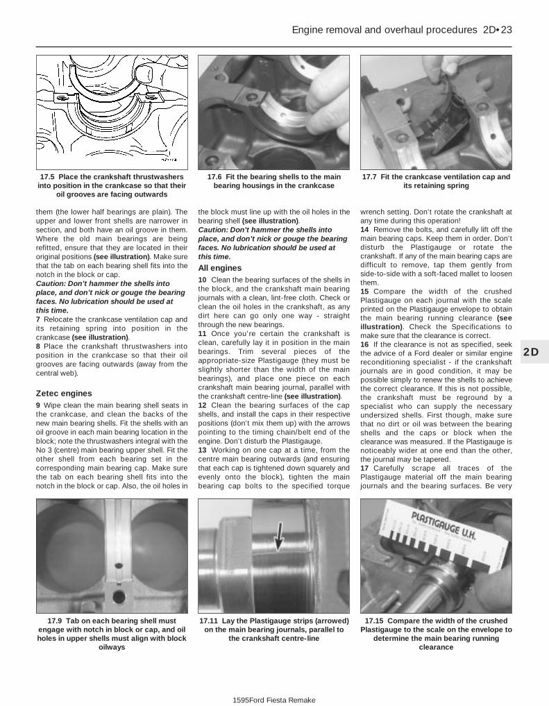
them (the lower half bearings are plain). Theupper and lower front shells are narrower insection, and both have an oil groove in them.Where the old main bearings are beingrefitted, ensure that they are located in theiroriginal positions (see illustration). Make surethat the tab on each bearing shell fits into thenotch in the block or cap. Caution: Don’t hammer the shells intoplace, and don’t nick or gouge the bearingfaces. No lubrication should be used atthis time.7 Relocate the crankcase ventilation cap andits retaining spring into position in thecrankcase (see illustration).8 Place the crankshaft thrustwashers intoposition in the crankcase so that their oilgrooves are facing outwards (away from thecentral web).
Zetec engines9 Wipe clean the main bearing shell seats inthe crankcase, and clean the backs of thenew main bearing shells. Fit the shells with anoil groove in each main bearing location in theblock; note the thrustwashers integral with theNo 3 (centre) main bearing upper shell. Fit theother shell from each bearing set in thecorresponding main bearing cap. Make surethe tab on each bearing shell fits into thenotch in the block or cap. Also, the oil holes in
the block must line up with the oil holes in thebearing shell (see illustration). Caution: Don’t hammer the shells intoplace, and don’t nick or gouge the bearingfaces. No lubrication should be used atthis time.
All engines10 Clean the bearing surfaces of the shells inthe block, and the crankshaft main bearingjournals with a clean, lint-free cloth. Check orclean the oil holes in the crankshaft, as anydirt here can go only one way - straightthrough the new bearings.11 Once you’re certain the crankshaft isclean, carefully lay it in position in the mainbearings. Trim several pieces of theappropriate-size Plastigauge (they must beslightly shorter than the width of the mainbearings), and place one piece on eachcrankshaft main bearing journal, parallel withthe crankshaft centre-line (see illustration).12 Clean the bearing surfaces of the capshells, and install the caps in their respectivepositions (don’t mix them up) with the arrowspointing to the timing chain/belt end of theengine. Don’t disturb the Plastigauge.13 Working on one cap at a time, from thecentre main bearing outwards (and ensuringthat each cap is tightened down squarely andevenly onto the block), tighten the mainbearing cap bolts to the specified torque
wrench setting. Don’t rotate the crankshaft atany time during this operation!14 Remove the bolts, and carefully lift off themain bearing caps. Keep them in order. Don’tdisturb the Plastigauge or rotate thecrankshaft. If any of the main bearing caps aredifficult to remove, tap them gently fromside-to-side with a soft-faced mallet to loosenthem.15 Compare the width of the crushedPlastigauge on each journal with the scaleprinted on the Plastigauge envelope to obtainthe main bearing running clearance (seeillustration). Check the Specifications tomake sure that the clearance is correct.16 If the clearance is not as specified, seekthe advice of a Ford dealer or similar enginereconditioning specialist - if the crankshaftjournals are in good condition, it may bepossible simply to renew the shells to achievethe correct clearance. If this is not possible,the crankshaft must be reground by aspecialist who can supply the necessaryundersized shells. First though, make surethat no dirt or oil was between the bearingshells and the caps or block when theclearance was measured. If the Plastigauge isnoticeably wider at one end than the other,the journal may be tapered.17 Carefully scrape all traces of thePlastigauge material off the main bearingjournals and the bearing surfaces. Be very
Engine removal and overhaul procedures 2D•23
17.7 Fit the crankcase ventilation cap andits retaining spring
17.6 Fit the bearing shells to the mainbearing housings in the crankcase
17.15 Compare the width of the crushedPlastigauge to the scale on the envelope to
determine the main bearing runningclearance
17.11 Lay the Plastigauge strips (arrowed)on the main bearing journals, parallel to
the crankshaft centre-line
17.9 Tab on each bearing shell mustengage with notch in block or cap, and oilholes in upper shells must align with block
oilways
2D
1595Ford Fiesta Remake
17.5 Place the crankshaft thrustwashersinto position in the crankcase so that their
oil grooves are facing outwards

careful not to scratch the bearing - use yourfingernail or the edge of a credit card.
Final crankshaft refitting18 Carefully lift the crankshaft out of theengine. Clean the bearing surfaces of theshells in the block, then apply a thin, uniformlayer of clean molybdenum disulphide-basedgrease, engine assembly lubricant, or cleanengine oil to each surface. Coat thethrustwasher surfaces as well.19 Lubricate the crankshaft oil seal journalswith molybdenum disulphide-based grease,engine assembly lubricant, or clean engine oil.20 Make sure the crankshaft journals areclean, then lay the crankshaft back in place inthe block (see illustration). Clean the bearingsurfaces of the shells in the caps, thenlubricate them. Install the caps in theirrespective positions, with the arrows pointingto the timing belt/chain end of the engine.21 Working on one cap at a time, from thecentre main bearing outwards (and ensuringthat each cap is tightened down squarely andevenly onto the block), tighten the mainbearing cap bolts to the specified torquewrench setting.22 Rotate the crankshaft a number of timesby hand, to check for any obvious binding.23 Check the crankshaft endfloat (see Sec-tion 12). It should be correct if the crankshaftthrust faces aren’t worn or damaged.24 Refit the crankshaft left-hand oil sealcarrier, and install a new seal (see Part A, B or C of this Chapter according to engine type).
18 Piston/connecting rodassemblies - refitting and big-endbearing running clearance check
4Note: On HCS engines, new big-end bearingcap retaining bolts will be required forreassembly.1 Before refitting the piston/connecting rodassemblies, the cylinder bores must beperfectly clean, the top edge of each cylindermust be chamfered, and the crankshaft mustbe in place.2 Remove the big-end bearing cap from No 1cylinder connecting rod (refer to the marksnoted or made on removal). Remove theoriginal bearing shells, and wipe the bearingrecesses of the connecting rod and cap with aclean, lint-free cloth. They must be keptspotlessly-clean!
Big-end bearing runningclearance check3 Clean the back of the new upper bearingshell, fit it to the connecting rod, then fit theother shell of the bearing set to the big-endbearing cap. Make sure that the tab on eachshell fits into the notch in the rod or caprecess (see illustration). Caution: Don’t hammer the shells intoplace, and don’t nick or gouge the bearingface. Don’t lubricate the bearing at thistime.4 It’s critically important that all matingsurfaces of the bearing components areperfectly clean and oil-free when they’reassembled.5 Position the piston ring gaps as describedin Section 16, lubricate the piston and ringswith clean engine oil, and attach a piston ringcompressor to the piston. Leave the skirtprotruding about a quarter-inch, to guide thepiston into the cylinder bore. The rings mustbe compressed until they’re flush with thepiston.6 Rotate the crankshaft until No 1 crankpin(big-end) journal is at BDC (Bottom DeadCentre), and apply a coat of engine oil to thecylinder walls.7 Arrange the No 1 piston/connecting rodassembly so that the arrow on the piston
crown points to the timing belt/chain end ofthe engine. Gently insert the assembly into theNo 1 cylinder bore, and rest the bottom edgeof the ring compressor on the engine block.8 Tap the top edge of the ring compressor tomake sure it’s contacting the block around itsentire circumference.9 Gently tap on the top of the piston with theend of a wooden hammer handle (seeillustration), while guiding the connectingrod’s big-end onto the crankpin. The pistonrings may try to pop out of the ringcompressor just before entering the cylinderbore, so keep some pressure on the ringcompressor. Work slowly, and if anyresistance is felt as the piston enters thecylinder, stop immediately. Find out what’sbinding, and fix it before proceeding. Do not,for any reason, force the piston into thecylinder - you might break a ring and/or thepiston.10 To check the big-end bearing runningclearance, cut a piece of the appropriate-sizePlastigauge slightly shorter than the width ofthe connecting rod bearing, and lay it in placeon the No 1 crankpin (big-end) journal, parallelwith the crankshaft centre-line (seeillustration 17.11).11 Clean the connecting rod-to-cap matingsurfaces, and refit the big-end bearing cap.Tighten the cap bolts evenly - on the HCS andZetec engines, first use a torque wrench totighten the bolts to the Stage 1 torque setting,then use an ordinary socket extension bar andan angle gauge to tighten the bolts furtherthrough the Stage 2 angle (see illustration).On the CVH and PTE engines, tighten thebolts progressively to the specified torque;further angle-tightening is not required onthese engines. Use a thin-wall socket, toavoid erroneous torque readings that canresult if the socket is wedged between thecap and nut. If the socket tends to wedgeitself between the nut and the cap, lift up on itslightly until it no longer contacts the cap.Don’t rotate the crankshaft at any time duringthis operation!12 Unscrew the bolts and detach the cap,being very careful not to disturb thePlastigauge.13 Compare the width of the crushed
2D•24 Engine removal and overhaul procedures
18.11 Angle-tightening the big-end boltsusing the correct tool
18.9 The piston can be driven gently intothe cylinder bore with the end of a wooden
or plastic hammer handle
18.3 Tab on each big-end bearing shellmust engage with notch in connecting rod
or cap
17.20 Refit the crankshaft after checkingbearing clearances
1595Ford Fiesta Remake

Plastigauge to the scale printed on thePlastigauge envelope, to obtain the runningclearance (see illustration 17.15). Compare itto the Specifications, to make sure theclearance is correct.14 If the clearance is not as specified, seekthe advice of a Ford dealer or similar enginereconditioning specialist - if the crankshaftjournals are in good condition it may bepossible simply to renew the shells to achievethe correct clearance. If this is not possible,the crankshaft must be reground by aspecialist, who can also supply the necessaryundersized shells. First though, make surethat no dirt or oil was trapped between thebearing shells and the connecting rod or capwhen the clearance was measured. Also,recheck the crankpin diameter. If thePlastigauge was wider at one end than theother, the crankpin journal may be tapered.15 Carefully scrape all traces of thePlastigauge material off the journal and thebearing surface. Be very careful not to scratchthe bearing - use your fingernail or the edge ofa credit card.
Final piston/connecting rodrefitting16 Make sure the bearing surfaces areperfectly clean, then apply a uniform layer ofclean molybdenum disulphide-based grease,engine assembly lubricant, or clean engine oil,to both of them. You’ll have to push the pistoninto the cylinder to expose the bearing surfaceof the shell in the connecting rod.17 Slide the connecting rod back into placeon the crankpin (big-end) journal, refit the big-end bearing cap, and then tighten the bolts asdescribed above.18 Repeat the entire procedure for theremaining piston/connecting rod assemblies.19 The important points to remember are:a) Keep the backs of the bearing shells and
the recesses of the connecting rods andcaps perfectly clean when assemblingthem.
b) Make sure you have the correctpiston/rod assembly for each cylinder -use the etched cylinder numbers toidentify the front-facing side of both therod and its cap.
c) The arrow on the piston crown must facethe timing belt/chain end of the engine.
d) Lubricate the cylinder bores with cleanengine oil.
e) Lubricate the bearing surfaces whenrefitting the big-end bearing caps after therunning clearance has been checked.
20 After all the piston/connecting rodassemblies have been properly installed,rotate the crankshaft a number of times byhand, to check for any obvious binding.21 On HCS engines, if the oil pick-up pipeand strainer was removed, this is a good timeto refit it. First clean the joint area, then coatthe area indicated with the specified activator(available from Ford dealers) (seeillustration). Wait for a period of ten minutes,then smear the shaded area with the specifiedadhesive and immediately press the inlet pipeinto position in the crankcase.
19 Engine - initial start-up afteroverhaul 1
1 With the engine refitted in the vehicle,double-check the engine oil and coolantlevels. Make a final check that everything hasbeen reconnected, and that there are no toolsor rags left in the engine compartment.2 With the spark plugs removed and theignition system disabled by unplugging theignition coil’s electrical connector, remove thefuel pump fuse (fuel injection engines) todisconnect the fuel pump (see Chapter 12).Turn the engine on the starter until the oilpressure warning light goes out.3 Refit the spark plugs, and connect all thespark plug (HT) leads (Chapter 1). Reconnectthe ignition coil. On fuel injection engines, refit
the fuel pump fuse, switch on the ignition andlisten for the fuel pump; it will run for a littlelonger than usual, due to the lack of pressurein the system.4 Start the engine, noting that this also maytake a little longer than usual, due to the fuelsystem components being empty.5 While the engine is idling, check for fuel,coolant and oil leaks. Don’t be alarmed ifthere are some odd smells and smoke fromparts getting hot and burning off oil deposits.If the hydraulic tappets (where applicable)have been disturbed, some valve gear noisemay be heard at first; this should disappear asthe oil circulates fully around the engine, andnormal pressure is restored in the tappets.6 Keep the engine idling until hot water is feltcirculating through the top hose, check that itidles reasonably smoothly and at the usualspeed, then switch it off.7 After a few minutes, recheck the oil andcoolant levels, and top-up as necessary(Chapter 1).8 If they were tightened as described, there isno need to re-tighten the cylinder head boltsonce the engine has first run after reassembly- in fact, Ford state that the bolts must not bere-tightened.9 If new components such as pistons, ringsor crankshaft bearings have been fitted, theengine must be run-in for the first 500 miles(800 km). Do not operate the engine at full-throttle, or allow it to labour in any gear duringthis period. It is recommended that the oil andfilter be changed at the end of this period.
Engine removal and overhaul procedures 2D•25
18.21 Oil inlet pipe refitting details on the HCS engine
A Area of sealant application - dimensions in mmB Edge must be parallel with engine longitudinal axis
2D
1595Ford Fiesta Remake

2D•26 Engine removal and overhaul procedures
1595Ford Fiesta Remake
Notes

3
1595Ford Fiesta Remake
CoolantMixture type . . . . . . . . . . . . . . . . . . . . . . . . . . . . . . . . . . . . . . . . . . . . . . See Chapter 1Cooling system capacity . . . . . . . . . . . . . . . . . . . . . . . . . . . . . . . . . . . . See Chapter 1
System pressurePressure test . . . . . . . . . . . . . . . . . . . . . . . . . . . . . . . . . . . . . . . . . . . . . . 1.2 bars - should hold this pressure for at least 10 seconds
Expansion tank filler capPressure rating . . . . . . . . . . . . . . . . . . . . . . . . . . . . . . . . . . . . . . . . . . . . 1.0 to 1.4 bars approximately - see cap for actual value
ThermostatStarts to open . . . . . . . . . . . . . . . . . . . . . . . . . . . . . . . . . . . . . . . . . . . . . 85ºC to 89ºC
Coolant temperature sensorResistance:
At 0ºC . . . . . . . . . . . . . . . . . . . . . . . . . . . . . . . . . . . . . . . . . . . . . . . . . 89 to 102 kilohmsAt 20ºC . . . . . . . . . . . . . . . . . . . . . . . . . . . . . . . . . . . . . . . . . . . . . . . . 35 to 40 kilohmsAt 100ºC . . . . . . . . . . . . . . . . . . . . . . . . . . . . . . . . . . . . . . . . . . . . . . . 1.9 to 2.5 kilohmsAt 120ºC . . . . . . . . . . . . . . . . . . . . . . . . . . . . . . . . . . . . . . . . . . . . . . . 1.0 to 1.4 kilohms
Chapter 3Cooling, heating and ventilation systems
Antifreeze - general information . . . . . . . . . . . . . . . . . . . . . . . . . . . . 2Auxiliary drivebelt check and renewal . . . . . . . . . . . . . . .See Chapter 1Coolant level check . . . . . . . . . . . . . . . . . . . . . . .See “Weekly Checks”Cooling system - draining . . . . . . . . . . . . . . . . . . . . . . . .See Chapter 1Cooling system - filling . . . . . . . . . . . . . . . . . . . . . . . . . .See Chapter 1Cooling system - flushing . . . . . . . . . . . . . . . . . . . . . . . .See Chapter 1Cooling system electrical switches and sensors - testing, removal
and refitting . . . . . . . . . . . . . . . . . . . . . . . . . . . . . . . . . . . . . . . . . . 6Cooling system hoses - disconnection and renewal . . . . . . . . . . . . 3General information and precautions . . . . . . . . . . . . . . . . . . . . . . . . 1
Heater/ventilation components - removal and refitting . . . . . . . . . . . 11Radiator and expansion tank - removal, inspection and refitting . . . 7Radiator electric cooling fan assembly - testing, removal and
refitting . . . . . . . . . . . . . . . . . . . . . . . . . . . . . . . . . . . . . . . . . . . . . . 5Thermostat - removal, testing and refitting . . . . . . . . . . . . . . . . . . . . 4Underbonnet check for fluid leaks and hose condition . .See Chapter 1Water pump (CVH and PTE engines) - removal and refitting . . . . . . 9Water pump (HCS engines) - removal and refitting . . . . . . . . . . . . . 8Water pump (Zetec engines) - removal and refitting . . . . . . . . . . . . . 10
3•1
Specifications
Contents
Easy, suitable fornovice with littleexperience
Fairly easy, suitablefor beginner withsome experience
Fairly difficult,suitable for competentDIY mechanic
Difficult, suitable forexperienced DIYmechanic
Very difficult,suitable for expert DIYor professional
Degrees of difficulty
54321

Torque wrench settings Nm lbf ftThermostat housing to cylinder head:
HCS engines . . . . . . . . . . . . . . . . . . . . . . . . . . . . . . . . . . . . . . . . . . . . 17 to 21 13 to 16CVH engines . . . . . . . . . . . . . . . . . . . . . . . . . . . . . . . . . . . . . . . . . . . . 9 to 12 7 to 9PTE engines . . . . . . . . . . . . . . . . . . . . . . . . . . . . . . . . . . . . . . . . . . . . 9 7Zetec engines . . . . . . . . . . . . . . . . . . . . . . . . . . . . . . . . . . . . . . . . . . . 17 to 21 13 to 16
Water outlet to thermostat housing (Zetec engines) . . . . . . . . . . . . . . . 9 to 12 7 to 9Water pump pulley . . . . . . . . . . . . . . . . . . . . . . . . . . . . . . . . . . . . . . . . . 10 7.5Water pump retaining bolts:
HCS, CVH and PTE engines . . . . . . . . . . . . . . . . . . . . . . . . . . . . . . . . 8 6Zetec engines . . . . . . . . . . . . . . . . . . . . . . . . . . . . . . . . . . . . . . . . . . . 18 13
Coolant temperature gauge sender . . . . . . . . . . . . . . . . . . . . . . . . . . . . 6 4Coolant temperature sensor:
HCS engines . . . . . . . . . . . . . . . . . . . . . . . . . . . . . . . . . . . . . . . . . . . . 23 17CVH engines:
1.4 litre models . . . . . . . . . . . . . . . . . . . . . . . . . . . . . . . . . . . . . . . . 19 141.6 litre models . . . . . . . . . . . . . . . . . . . . . . . . . . . . . . . . . . . . . . . . 15 11
PTE engines . . . . . . . . . . . . . . . . . . . . . . . . . . . . . . . . . . . . . . . . . . . . 15 11Zetec engines . . . . . . . . . . . . . . . . . . . . . . . . . . . . . . . . . . . . . . . . . . . 15 11
Radiator mounting bolts . . . . . . . . . . . . . . . . . . . . . . . . . . . . . . . . . . . . . 20 to 27 15 to 20Radiator cooling fan shroud retaining bolt . . . . . . . . . . . . . . . . . . . . . . . 3 to 5 2 to 4Radiator cooling fan motor to shroud nuts . . . . . . . . . . . . . . . . . . . . . . . 9 to 12 7 to 9Automatic transmission fluid cooling pipe connections to radiator . . . . 17 to 21 13 to 16
3•2 Cooling, heating and ventilation systems
1595Ford Fiesta Remake
1 General information andprecautions
Engine cooling systemThe cooling system is of the pressurised
type consisting of a belt-driven pump,aluminium crossflow radiator, expansion tank,electric cooling fan and a thermostat. Thesystem functions as follows. Cold coolant inthe bottom of the radiator passes through thebottom hose to the water pump, where it ispumped around the cylinder block and headpassages. After cooling the cylinder bores,combustion surfaces and valve seats, thecoolant reaches the underside of thethermostat, which is initially closed. Thecoolant passes through the heater and inlet manifold and is returned to the waterpump.
When the engine is cold, the coolantcirculates through the cylinder block, cylinderhead, heater and inlet manifold. When thecoolant reaches a predetermined tempera-ture, the thermostat opens, and the coolantthen passes through the top hose to the radiator. As the coolant circulates through the radiator, it is cooled by the inrushof air when the car is in forward motion.Airflow is supplemented by the action of theelectric cooling fan when necessary. Uponreaching the bottom of the radiator, thecoolant is now cooled, and the cycle isrepeated.
When the engine is at normal operatingtemperature, the coolant expands, and someof it is displaced into the expansion tank. Thiscoolant collects in the tank, and is returned tothe radiator when the system cools.
The electric cooling fan, mounted behindthe radiator, is controlled by a thermostatic
switch. At a predetermined coolanttemperature, the switch contacts close, thusactuating the fan.
Heating/ventilation systemThe heating system consists of a blower fan
and heater matrix (radiator) located in theheater unit, with hoses connecting the heatermatrix to the engine cooling system. Hotengine coolant is circulated through theheater matrix. Air is forced through the matrixby the three-speed fan, dispersing the heatinto the vehicle interior. Fresh air enters thevehicle through the grille slats between thewindscreen and the rear edge of the bonnet,and passes through to the heater casing.Depending on the position of the heater slidecontrols, which actuate cable-controlled flapvalves within the heater casing, the air isdistributed, either heated or unheated, via theducting to outlet vents. The main outlet ventsin the facia are adjustable. The airflow passesthrough the passenger compartment to exit atthe rear of the vehicle.
PrecautionsWarning: DO NOT attempt toremove the expansion tank fillercap, or to disturb any part of thecooling system, while it or the
engine is hot, as there is a very great riskof scalding. If the expansion tank filler capmust be removed before the engine andradiator have fully cooled down (eventhough this is not recommended) thepressure in the cooling system must firstbe released. Cover the cap with a thicklayer of cloth, to avoid scalding, and slowlyunscrew the filler cap until a hissing soundcan be heard. When the hissing hasstopped, showing that pressure isreleased, slowly unscrew the filler capfurther until it can be removed; if morehissing sounds are heard, wait until they
have stopped before unscrewing the capcompletely. At all times, keep well awayfrom the filler opening.
Warning: Do not allow antifreezeto come in contact with yourskin, or with the paintedsurfaces of the vehicle. Rinse off
spills immediately with plenty of water.Never leave antifreeze lying around in anopen container, or in a puddle in thedriveway or on the garage floor. Childrenand pets are attracted by its sweet smell,but antifreeze can be fatal if ingested.
Warning: If the engine is hot, theelectric cooling fan may startrotating even if the engine is notrunning, so be careful to keep
hands, hair and loose clothing well clearwhen working in the engine compartment.
2 Antifreeze - general information
Note: Refer to the warnings given in Section 1of this Chapter before proceeding.
The cooling system should be filled with awater/ethylene glycol-based antifreezesolution, of a strength which will preventfreezing down to at least -25ºC, or lower if thelocal climate requires it. Antifreeze alsoprovides protection against corrosion, andincreases the coolant boiling point.
The cooling system should be maintainedaccording to the schedule described inChapter 1. If antifreeze is used that is not toFord’s specification, old or contaminatedcoolant mixtures are likely to cause damage,and encourage the formation of corrosion andscale in the system. Use distilled water with theantifreeze, if available - if not, be sure to useonly soft water. Clean rainwater is suitable.

Before adding antifreeze, check all hosesand hose connections, because antifreezetends to leak through very small openings.Engines don’t normally consume coolant, so ifthe level falls regularly, find the cause andcorrect it.
The exact mixture of antifreeze-to-waterwhich you should use depends on the relativeweather conditions. The mixture shouldcontain at least 40% antifreeze, but not morethan 70%. Consult the mixture ratio chart onthe antifreeze container before addingcoolant. Hydrometers are available at mostautomotive accessory shops to test thecoolant. Use only good-quality ethylene-glycol-based antifreeze which meets thevehicle manufacturer’s specifications.
3 Cooling system hoses -disconnection and renewal 1
Note: Refer to the warnings given in Section 1of this Chapter before starting work.1 If the checks described in Chapter 1 reveala faulty hose, it must be renewed as follows.2 First drain the cooling system (see Chap-ter 1); if the antifreeze is not due for renewal,the drained coolant may be re-used, if it iscollected in a clean container.3 To disconnect any hose, use a pair of pliersto release the spring clamps (or a screwdriverto slacken screw-type clamps), then movethem along the hose clear of the union.Carefully work the hose off its stubs. Thehoses can be removed with relative easewhen new - on an older car, they may havestuck.4 If a hose proves stubborn, try to release itby rotating it on its unions before attemptingto work it off. Gently prise the end of the hosewith a blunt instrument (such as a flat-bladedscrewdriver), but do not apply too much force,and take care not to damage the pipe stubs orhoses. Note in particular that the radiator hoseunions are fragile; do not use excessive forcewhen attempting to remove the hoses.
5 When refitting a hose, first slide the clampsonto the hose, then work the hose onto itsunions.
6 Work each hose end fully onto its union,then check that the hose is settled correctlyand is properly routed. Slide each clip alongthe hose until it is behind the union flared end,before tightening it securely.7 Refill the system with coolant (see Chap-ter 1).8 Check carefully for leaks as soon aspossible after disturbing any part of thecooling system.
4 Thermostat - removal, testing and refitting 1
Note: Refer to the warnings given in Section 1of this Chapter before starting work.
Removal1 Disconnect the battery negative (earth) lead(refer to Chapter 5A, Section 1).2 Drain the cooling system (see Chapter 1).3 Refer to the relevant Part of Chapter 4 andremove the air cleaner or air inlet hoses,according to engine type as necessary, togain access to the thermostat housing.
HCS, CVH and PTE engines4 Loosen the clips, and disconnect theradiator top hose, expansion tank hose and,where applicable, the heater hose from thethermostat housing (see illustrations).
5 Disconnect the thermostatic switch wiremulti-plug from the thermostat housing.6 Unscrew the retaining bolts, and removethe thermostat housing (see illustration).7 Remove the gasket from the mating face ofthe thermostat housing, then using suitablepliers, compress the thermostat retaining clip(where applicable) and remove it from thehousing. Extract the thermostat from the housing (noting its direction of fitting) andwhere applicable, remove the O-ring seal (seeillustrations).
Zetec engines8 Disconnect the expansion tank hose and
Cooling, heating and ventilation systems 3•3
4.4b Disconnecting the expansion tanktop hose from the thermostat housing
(HCS engine). Radiator cooling fan thermalswitch (arrowed)
4.4a Thermostat housing hoseattachments on the CVH engine
4.7b Exploded view of thermostat andhousing (CVH and PTE engines)
A Sealing ring C Retaining clipB Thermostat
4.7a Removing the gasket and thermostatfrom an HCS engine
4.6 Removing the thermostat housingfrom a CVH engine
3
1595Ford Fiesta Remake
If all else fails, cut the hosewith a sharp knife, then slitit so that it can be peeled offin two pieces. Although this
may prove expensive if the hose isotherwise undamaged, it is preferableto buying a new radiator.
If the hose is stiff, use a littlesoapy water as a lubricant,or soften the hose bysoaking it in hot water. Do
not use oil or grease, which may attackthe rubber.

the radiator top hose from the thermostathousing’s water outlet (see illustration).9 Unscrew the retaining bolts, and removethe water outlet from the thermostat housing.10 Withdraw the thermostat from the housingnoting the position of the air bleed valve, andhow the thermostat is installed (which end isfacing outwards) (see illustration).
Testing
General check11 Before assuming the thermostat is toblame for a cooling system problem, checkthe coolant level, auxiliary drivebelt tensionand condition (see Chapter 1) andtemperature gauge operation.12 If the engine seems to be taking a longtime to warm up (based on heater output ortemperature gauge operation), the thermostatis probably stuck open. Renew the thermostat.13 If the engine runs hot, use your hand tocheck the temperature of the radiator tophose. If the hose isn’t hot, but the engine is,the thermostat is probably stuck closed,preventing the coolant inside the engine fromescaping to the radiator - renew thethermostat. Caution: Don’t drive the vehicle without athermostat. The lack of a thermostat willslow warm-up time. The enginemanagement system’s ECU will then stayin warm-up mode for longer thannecessary, causing emissions and fueleconomy to suffer.
14 If the radiator top hose is hot, it meansthat the coolant is flowing and the thermostatis open. Consult the “Fault finding” section atthe end of this manual to assist in tracingpossible cooling system faults.
Thermostat test15 If the thermostat remains in the openposition at room temperature, it is faulty, andmust be renewed as a matter of course.16 To test it fully, suspend the (closed)thermostat on a length of string in a containerof cold water, with a thermometer beside it;ensure that neither touches the side of thecontainer (see illustration).17 Heat the water, and check the temperatureat which the thermostat begins to open;compare this value with that specified. It’s notpossible to check the fully-open temperature,because this occurs above the boiling point ofwater at normal atmospheric pressure. If thetemperature at which the thermostat began toopen was as specified, then it is most likelythat the thermostat is working properly at alltemperatures. Remove the thermostat, andallow it to cool down; check that it closes fully.18 If the thermostat does not open and closeas described, if it sticks in either position, or ifit does not open at the specified temperature,it must be renewed.
RefittingAll models19 Refitting is a reversal of removal. Cleanthe mating surfaces carefully, and renew the
thermostat’s O-ring seal or housing gasket, asapplicable.20 On Zetec engines, ensure that thethermostat is fitted with its air bleed valveuppermost.21 Tighten the thermostat housing/wateroutlet bolts to the specified torque.22 Refill the cooling system (see Chapter 1).23 Refit the air cleaner or air inlet components,as applicable, if removed for access.24 Start the engine and allow it to reachnormal operating temperature, then check forleaks and proper thermostat operation.
5 Radiator electric cooling fanassembly - testing, removaland refitting
2Note: Refer to the warnings given in Section 1of this Chapter before starting work.
Testing1 If it is suspected that the cooling fan is notoperating when high engine temperaturewould normally require it to do so, first checkthe relevant fuses and relays (see Chapter 12).2 Detach the wiring multi-plug from thethermostatic switch, which is located either inthe thermostat housing or at the right-hand endof the radiator, next to the bottom hose (seeillustration). Using a suitable piece of wire,bridge the two connections within the plug.Switch the ignition on and check if the coolingfan operates. If the fan now operates, thethermostatic switch is at fault, and should berenewed as described in Section 6. Remove thebridging wire from the plug, and reconnect thewiring connector to complete the test.3 If the fan failed to operate in the previoustest, either the fan motor is at fault, or there isa fault in the wiring loom (see Chapter 12 fortesting details).
Removal
All models except Turbo4 Disconnect the battery negative (earth) lead(refer to Chapter 5A, Section 1).5 Detach the wiring multi-plug from the fanmotor and unclip the wiring from the retainingclips on the shroud (see illustration).
3•4 Cooling, heating and ventilation systems
5.5 Disconnecting the multi-plug from theradiator cooling fan motor
5.2 Radiator cooling fan thermostaticswitch location on CVH engine thermostat
housing
4.16 Testing the thermostat4.10 Zetec engine thermostat removal4.8 Disconnect the coolant hoses from thewater outlet on a Zetec engine
1595Ford Fiesta Remake

6 Unscrew the nut securing the cooling fanshroud to the radiator, noting the insulatingwasher arrangement, then lift the fan shroudand motor assembly from the vehicle (seeillustration).7 To separate the fan from the motor shaft,first remove its retaining clip and washer, thenwithdraw the fan (see illustration). A new clipwill be needed upon reassembly. Remove thethree nuts securing the motor to the shroudand separate the two components.
Turbo models8 Disconnect the battery negative (earth) lead(refer to Chapter 5A, Section 1).9 Undo the two retaining screws and movethe HT lead bracket clear of the working area,disconnecting the HT leads as required.10 Disconnect the fan motor wiring multi-plug and the two auxiliary lamp wiring multi-plugs. Unclip the wiring from any localretaining clips.11 Remove the front bumper as described inChapter 11.12 Undo the two lower fan shroud retainingbolts, release the shroud upper locatingtongue from the radiator and withdraw theassembly from the front of the car.13 To separate the fan from the motor shaft,pull off the fan guard from the shroud, flattenback the raised lockwasher tab, and unscrewclockwise (a left-hand thread is employed)the nut securing the fan to the motor shaft.Remove the fan then undo the three nutssecuring the motor to the shroud andseparate the two components.
Refitting
All models14 Refitting is a reversal of the removalprocedure. On non-Turbo models, ensure thatthe locating tags on the base of the shroudlocate correctly in their slots in the bodycrossmember. On Turbo models, if the fanwas removed, use a new lockwasher whenrefitting. On all models, ensure that the wiringconnections are cleanly and securely made,and locate the loom in the retaining clips.
6 Cooling system electricalswitches and sensors -testing, removal and refitting
2Note: Refer to the warnings given in Section 1of this Chapter before starting work.
Coolant temperature gaugesender
Testing1 If the coolant temperature gauge isinoperative, check the fuses first (see Chap-ter 12).2 If the gauge indicates overheating at anytime, consult the “Fault finding” section at theend of this manual, to assist in tracingpossible cooling system faults.
3 If the gauge indicates overheating shortlyafter the engine is started from cold,disconnect the temperature gauge sender’swiring multi-plug. The sender is located belowthe thermostat housing on HCS engines,adjacent to the thermostat housing on CVHand PTE engines, and on the forward-facingside of the thermostat housing on Zetecengines. If the gauge reading now drops,renew the sender. If the reading remains high,the wire to the gauge may be shorted to earth,or the gauge is faulty.4 If the gauge fails to indicate after the enginehas been warmed up (approximately 10 minutes) and the fuses are known to besound, switch off the engine. Disconnect thesender’s wiring multi-plug, and use a jumperwire to ground the connector to a clean earthpoint (bare metal) on the engine. Switch onthe ignition without starting the engine. If the gauge now indicates Hot, renew thesender.5 If the gauge still does not work, the circuitmay be open, or the gauge may be faulty. SeeChapter 12 for additional information.
Removal6 Refer to the relevant Part of Chapter 4 andremove the air cleaner or air inlet hoses,according to engine type as necessary, togain access to the sender unit.7 Drain the cooling system (see Chapter 1).8 On Zetec engines, disconnect theexpansion tank coolant hose and the radiatortop hose from the thermostat housing’s wateroutlet.9 Disconnect the wiring multi-plug from thesender unit.10 Unscrew the sender and withdraw it.
Refitting11 Clean as thoroughly as possible thesender unit location, then apply a light coat ofsealant to the sender’s threads. Screw in thesender, tighten it to the specified torque, andreconnect the wiring multi-plug.12 Reconnect the hoses, and refit anycomponents disconnected for access. Refillor top-up the cooling system (see “WeeklyChecks” or Chapter 1) and run the engine. Check for leaks and proper gaugeoperation.
Engine coolant temperaturesensor
Testing13 Disconnect the battery negative (earth)lead (see Chapter 5A, Section 1).14 Locate the coolant temperature sensor,which will be found below the inlet manifoldon HCS engines, on the side or centre of theinlet manifold on CVH and PTE engines, or ontop of the thermostat housing on Zetecengines. Once located, refer to the relevantPart of Chapter 4 and remove the air cleaneror air inlet hoses, according to engine type asnecessary, to improve access to the sensorunit.15 Disconnect the wiring multi-plug from thesensor.16 Using an ohmmeter, measure theresistance between the sensor terminals.Depending on the temperature of the sensortip, the resistance measured will vary, butshould be within the broad limits given in theSpecifications of this Chapter. If the sensor’stemperature is varied - by removing it (seebelow) and placing it in a freezer for a while, orby warming it gently - its resistance shouldalter accordingly.17 If the results obtained show the sensor tobe faulty, renew it.18 On completion, reconnect the wiringmulti-plug and refit any components removedfor access, then reconnect the battery.
Removal19 Disconnect the battery negative (earth)lead (see Chapter 5A, Section 1).20 Locate the sensor as describedpreviously, and remove any components asnecessary for access.21 Drain the cooling system (see Chapter 1).22 Disconnect the wiring multi-plug from thesensor.23 Unscrew the sensor and withdraw it.
Refitting24 Clean as thoroughly as possible thesensor location, then apply a light coat ofsealant to the sensor’s threads. Refit andtighten the sensor to the specified torque
Cooling, heating and ventilation systems 3•5
5.7 Nuts securing fan motor to shroud (A),and shroud to body crossmember locating
tags (B). Inset shows fan to motor shaftretaining clip (arrowed)
5.6 Radiator cooling fan shroud securingnut (arrowed)
3
1595Ford Fiesta Remake

wrench setting, and reconnect the multi-plug.25 Refit any components disconnected foraccess then refill the cooling system (seeChapter 1).
Radiator electric cooling fanthermostatic switch
Testing26 Refer to the procedures contained inSection 5.
Removal27 Disconnect the battery negative (earth)lead (refer to Chapter 5A, Section 1).28 Drain the cooling system (see Chapter 1).29 Disconnect the wiring multi-plug from thethermostatic switch, and then unscrew theswitch from the thermostat housing orradiator side tank, as applicable. Remove thesealing washer.
Refitting30 Refitting is a reversal of removal, but fit anew sealing washer and tighten the switchsecurely. Refill the cooling system asdescribed in Chapter 1, then reconnect thebattery.
7 Radiator and expansion tank- removal, inspection andrefitting
2Note: Refer to the warnings given in Section 1of this Chapter before starting work.
Radiator
Removal (all models except Turbo)1 Disconnect the battery negative (earth) lead(refer to Chapter 5A, Section 1).2 Drain the cooling system (see Chapter 1).3 Remove the radiator cooling fan assemblyas described in Section 5.4 Release the hose clips and disconnect thehoses from the radiator. Additionally, on
automatic transmission models, disconnectthe transmission fluid cooling pipeconnections fitting blanking plugs to preventexcessive fluid loss (see illustration).5 On Zetec engine models, disconnect thewiring multi-plug from the cooling fanthermostatic switch6 Remove the radiator securing bolts and liftthe radiator out of its locating slots in the bodycrossmember. Note rubber insulators fitted tothe locating lugs on the base of the radiator(see illustrations).7 With the radiator removed, it can beinspected for leaks and damage. If it needsrepair, have a radiator specialist or dealerservice department perform the work, asspecial techniques are required.8 Insects and dirt can be removed from theradiator with a garden hose or a soft brush.Don’t bend the cooling fins as this is done.
Removal (Turbo models)9 Disconnect the battery negative (earth) lead(refer to Chapter 5A, Section 1).10 Drain the cooling system (see Chapter 1).11 Remove the radiator cooling fan assemblyas described in Section 5.12 Release the hose clips and disconnect thehoses from the radiator.13 Disconnect the turbocharger coolant feedby slackening its clamp and pulling the hose(at the radiator rear right-hand side) off theturbocharger’s metal pipe.14 Remove the intercooler, as described inChapter 4C.15 Remove its three retaining screws, andwithdraw the exhaust manifold heat shield.
16 Lift the radiator out of its locating slots inthe body crossmember. Note rubberinsulators fitted to the locating lugs on thebase of the radiator.17 Clean and inspect the radiator withreference to paragraphs 7 and 8 above.
Refitting (all models)18 Refitting is a reversal of removal, butcheck the rubber insulators, and if necessaryrenew them. Refill the cooling system withreference to Chapter 1. On automatictransmission models check, and if necessarytop-up, the automatic transmission fluid level(Chapter 1).
Expansion tank
Removal19 Partially drain the cooling system, so thatthe coolant level drops below the expansiontank. Refer to Chapter 1 for details.20 Before disconnecting the coolant hosesfrom the expansion tank, it is advisable toclamp them just short of their connections tothe expansion tank, to prevent spillage ofcoolant and the ingress of air when they aredetached.21 Loosen off the coolant hose clips at theexpansion tank, and detach the hoses from it.If they are not clamped, secure them so thattheir ends are raised, to minimise coolantspillage.22 Remove the single bolt retaining theexpansion tank, and slide the other side of thetank free from its retaining bracket (seeillustrations).
3•6 Cooling, heating and ventilation systems
7.22b . . . and release the expansion tankfrom its retaining bracket
7.22a Remove the single bolt retaining theexpansion tank . . .
7.6b Rubber insulator on radiator locatinglug
7.6a Radiator securing bolt, insulator andwasher
7.4 Automatic transmission fluid coolingpipe connections (arrowed) at the radiator
1595Ford Fiesta Remake
If leakage is the reason forremoving the radiator, bearin mind that minor leaks canoften be cured using a
radiator sealant with the radiator insitu.

Refitting23 Refit in the reverse order of removal. Top-up the cooling system as described in“Weekly Checks”.
8 Water pump (HCS engines) -removal and refitting 2
Note: Refer to the warnings given in Section 1of this Chapter before starting work.
Removal1 Disconnect the battery negative (earth) lead(refer to Chapter 5A, Section 1).2 Drain the cooling system (see Chapter 1).3 Slacken the water pump pulley retainingbolts, then remove the auxiliary drivebelt asdescribed in Chapter 1 (see illustration).4 Remove the retaining bolts, and remove thedrivebelt pulley from the water pump.5 Loosen off the coolant hose securing clips,and disconnect the hoses from the waterpump.6 Unscrew the retaining bolts, and withdrawthe water pump from the engine (seeillustration).7 No provision is made for the repair of thewater pump; if it is noisy or defective in anyway, it must be renewed.
Refitting8 Clean all traces of gasket from the engineand the water pump mating faces. Ensure thatthe mating faces are clean and dry. Note that the water pump gasket fitted duringproduction is integral with the timing covergasket, and this will need to be cut awayusing a sharp knife, keeping as close to thetiming cover as possible.9 Refitting is a reversal of the removalprocedure. Use a new gasket, lightly smearedwith jointing compound, and tighten theretaining bolts to the specified torque.10 Refit and adjust the auxiliary drivebelt asdescribed in Chapter 1.11 Refill the cooling system as described inChapter 1, and reconnect the battery.
9 Water pump (CVH and PTEengines) - removal and refitting
4Note: Refer to the warnings given in Section 1of this Chapter before starting work.
Removal1 Disconnect the battery negative (earth) lead(refer to Chapter 5A, Section 1).2 Drain the cooling system (see Chapter 1).3 Remove the timing belt and tensioner (seeChapter 2B). If the belt is fouled with coolant,it must be renewed as a matter of course.4 Loosen off the coolant hose retaining clip,and detach the coolant hose from the waterpump.5 Unscrew and remove the four boltssecuring the water pump to the front end faceof the cylinder block, and then withdraw thepump from the vehicle (see illustration).
Refitting6 Clean the engine water pump mating faces.Ensure that the mating faces are clean anddry.7 No provision is made for the repair of thewater pump; if it is noisy or defective in anyway, it must be renewed.8 Refitting is a reversal of the removalprocedure. Tighten the retaining bolts to thespecified torque, and ensure that the coolanthose connection to the water pump issecurely made.
9 Refit the timing belt and tensioner asdescribed in Chapter 2B.10 Refill the cooling system as described inChapter 1, and reconnect the battery.
10 Water pump (Zetec engines)- removal and refitting 4
Note: Refer to the warnings given in Section 1of this Chapter before starting work.
Removal1 Disconnect the battery negative (earth) lead(refer to Chapter 5A, Section 1).2 Drain the cooling system (see Chapter 1).3 Remove the timing belt and tensioner (seeChapter 2C). If the belt is fouled with coolant,it must be renewed as a matter of course.4 Disconnect the radiator bottom hose fromthe pump union.5 Unbolt and remove the water pump (seeillustrations). If the pump is to be renewed,unbolt the timing belt guide pulleys, andtransfer them to the new pump.
Refitting6 Clean the mating surfaces carefully; thegasket must be renewed whenever it isdisturbed.7 On refitting, use grease to stick the newgasket in place, refit the pump, and tightenthe pump bolts to the specified torque.8 The remainder of refitting is a reversal of the
Cooling, heating and ventilation systems 3•7
9.5 CVH engine timing belt tensionerretaining bolts (A) and water pump
securing bolts (B)
8.6 HCS engine water pump removal8.3 HCS engine water pump pulleyretaining bolts (arrowed)
10.5b . . . and remove the Zetec enginewater pump
10.5a Unscrew the bolts (arrowed) . . .
3
1595Ford Fiesta Remake

removal procedure. Refit the timing belt andtensioner as described in Chapter 2C, notingthat a new tensioner spring and retaining pinmust be fitted if the timing belt has beenremoved for the first time. Tighten allfasteners to the specified torque, and refill thesystem with coolant as described in Chap-ter 1.
11 Heater/ventilationcomponents - removal and refitting
3Heater controls1 Disconnect the battery negative (earth) lead(refer to Chapter 5A, Section 1).2 Refer to Chapter 12 and remove the radio.3 Pull off the heater fan motor control knob,then move the air distribution andtemperature controls fully to the right. Unclipand remove the heater slide facia towards theleft-hand side of the vehicle, removing theslide control knobs only as necessary, anddisconnecting its bulbholder (bayonet type) asit is withdrawn.4 Squeeze the two release tabs together onthe heater fan motor control switch, andremove it, disconnecting its multi-plug as it iswithdrawn.5 Disconnect the heater control cables fromthe heater casing assembly by releasing theouter cable abutments and disengaging the
cable inner cores from their flap operatingmechanisms (see illustration).6 Undo the three heater control panelsecuring screws, and remove the controlpanel (with its cables attached) from behindthe facia (see illustration).7 Disconnect the heater control cables fromtheir control panel levers, as required, byreleasing their outer cable clamping coversand inner cable core securing clips (seeillustrations).8 If renewing a heater control panel, note thatthe new unit, is supplied with control cablesand assembly aids fitted (see illustration).The assembly aids ensure correct heatercontrol adjustments during fitting, and mustbe removed thereafter.
9 Refitting is a reversal of the removalprocedure, adjusting the heater control cablesto complete. The adjustment is madeautomatically by moving the heater slidecontrol levers from their left-hand stop to theirright-hand stop. When moving the controllevers, a considerable amount of resistancemay be encountered, which must beovercome.
Heater fan motor and resistorassembly10 Disconnect the battery negative (earth)lead (refer to Chapter 5A, Section 1).11 Depending on engine type, refer to therelevant Part of Chapter 4 and remove the aircleaner if necessary, to gain access to thebulkhead panel in the engine compartment.12 Remove the expansion tank as describedin Section 7.13 Undo the retaining bolt and remove thejack and wheelbrace.14 Disconnect the modules on the bulkheadpanel. Release the wiring loom and anyconnectors, cable-ties and hoses from thebulkhead panel, and remove its rubber seal.15 Remove the bulkhead panel. The panel issecured by screws, with a nut at either end(behind the panel), and is removed in twosections.16 Detach and remove the cover from theheater fan motor assembly (see illustration).17 Disconnect the wiring from the heater fan
3•8 Cooling, heating and ventilation systems
11.16 Removing the cover from the heaterfan motor assembly
11.8 Heater control panel. Assembly aids (A) fitted to heater casing flap valve
end of cables
11.7c Releasing inner cable core fromheater control lever
11.7b . . . and removing it11.7a Releasing outer cable clampingcover . . .
11.6 Heater control panel securing screws (A), and fan motor control
switch (B)
11.5 Disengaging heater control cablefrom its flap operating mechanism on the
heater casing
1595Ford Fiesta Remake

motor and resistor assembly (seeillustration).18 Undo the two nuts securing the assemblyto the bulkhead and remove it from thevehicle.19 Detach the heater fan cover, havingreleased its two retaining clips.20 Release the heater fan motor retainingstrap from underneath, using a flat-bladedscrewdriver, and remove it. Remove theresistor assembly and/or heater fan motor, asrequired (see illustrations).21 Refitting is a reversal of the removal
procedure, ensuring that the heater fan motorwires are routed under the retaining strap, butare not pinched by it.
Heater matrixNote: Refer to the warnings given in Section 1of this Chapter before starting work.22 Disconnect the battery negative (earth)lead (refer to Chapter 5A, Section 1).23 Drain the cooling system (see Chapter 1).24 Release the hose clips and disconnect thetwo heater hoses from their dual heater matrixconnector on the bulkhead, at the rear of theengine compartment. Plug the hoses toprevent excessive coolant loss, collectingspillage and any remaining coolant from theheater matrix in a suitable container.25 Undo the screws securing the heater
matrix connector to the bulkhead, and detachits cover plate and gasket (see illustration).26 Where fitted, remove the centre consoleas described in Chapter 11.27 Unclip and detach the footwell vent fromthe base of the heater casing (seeillustration).28 Unclip the lower cover from the heatercasing and remove the heater matrix, beingcareful to avoid any residual coolant spillagein the passenger compartment (seeillustrations).29 Refitting is a reversal of the removalprocedure. On completion, refill the coolingsystem as described in Chapter 1.
Heater casing assembly30 Remove the facia, as described inChapter 11.31 Remove the heater matrix, as describedpreviously in this Section.32 Disconnect the heater control cables fromthe heater casing assembly as describedpreviously in this Section.33 Disconnect the side outlet vent ductingfrom the heater casing. The side outlet ductscan be removed by undoing the screwssecuring them to the bulkhead, as required.34 Undo the two heater casing securing nutsand remove the casing from the vehicle (seeillustration).35 Refitting is a reversal of the removalprocedure, with reference to the applicableChapters and Sections of this manual.
Cooling, heating and ventilation systems 3•9
11.20b Removing the heater fan motor11.20a Releasing the heater fan motorretaining strap from the underside of the
assembly
11.17 Disconnecting the wiring from theheater fan motor and resistor assembly
(arrowed)
11.34 Heater casing securing nuts(arrowed)
11.28b Withdrawing the heater matrix
11.27 Removing the footwell vent from thebase of the heater casing
11.25 Exploded view of the heater matrixconnections
A Cover plateB GasketC Heater matrix
connector pipe
D Hose clipsE Heater hosesF Screw
11.28a Unclipping the lower heater casingcover
3
1595Ford Fiesta Remake

3•10 Cooling, heating and ventilation systems
1595Ford Fiesta Remake
Notes

4A
1595Ford Fiesta Remake
GeneralSystem type . . . . . . . . . . . . . . . . . . . . . . . . . . . . . . . . . . . . . . . . . . . . . . Rear-mounted fuel tank, mechanical fuel pump, single Weber
carburettor
CarburettorType . . . . . . . . . . . . . . . . . . . . . . . . . . . . . . . . . . . . . . . . . . . . . . . . . . . . Single or twin choke, downdraughtApplication:
1.0 litre HCS engines . . . . . . . . . . . . . . . . . . . . . . . . . . . . . . . . . . . . . Weber (1V) TLM1.1 litre HCS engines . . . . . . . . . . . . . . . . . . . . . . . . . . . . . . . . . . . . . Weber (2V) TLDM1.3 HCS engines . . . . . . . . . . . . . . . . . . . . . . . . . . . . . . . . . . . . . . . . . Weber (2V) TLDM1.4 litre CVH engines . . . . . . . . . . . . . . . . . . . . . . . . . . . . . . . . . . . . . Weber (2V) DFTM1.6 litre CVH engines . . . . . . . . . . . . . . . . . . . . . . . . . . . . . . . . . . . . . Weber (2V) TLD
Fuel gradeFuel octane requirement:
Engines without catalytic converter* . . . . . . . . . . . . . . . . . . . . . . . . . . 95 RON unleaded or 97 RON leadedEngines with catalytic converter . . . . . . . . . . . . . . . . . . . . . . . . . . . . . 95 RON unleaded (leaded fuel must not be used)
*Refer to dealer for latest recommendations
Chapter 4 Part A:Fuel system - carburettor engines
Accelerator cable (CTX automatic transmission models) - adjustment . . . . . . . . . . . . . . . . . . . . . . . . . . . . . . . . . . . . . . . . . . . 4
Accelerator cable (manual transmission models) - removal, refitting and adjustment . . . . . . . . . . . . . . . . . . . . . . . . . . . . . . . . . . . . . . . 3
Accelerator pedal - removal and refitting . . . . . . . . . . . . . . . . . . . . . 5Accelerator pump diaphragm (Weber TLM carburettor) -
removal and refitting . . . . . . . . . . . . . . . . . . . . . . . . . . . . . . . . . . . 16Air cleaner - removal and refitting . . . . . . . . . . . . . . . . . . . . . . . . . . . 2Air cleaner element renewal . . . . . . . . . . . . . . . . . . . . . .See Chapter 1Automatic choke (Weber TLD carburettor) - adjustment . . . . . . . . . 33Automatic choke (Weber TLD carburettor) - removal, inspection
and refitting . . . . . . . . . . . . . . . . . . . . . . . . . . . . . . . . . . . . . . . . . . 34Carburettor (Weber DFTM) - description . . . . . . . . . . . . . . . . . . . . . 25Carburettor (Weber DFTM) - dismantling, cleaning, inspection
and reassembly . . . . . . . . . . . . . . . . . . . . . . . . . . . . . . . . . . . . . . . 29Carburettor (Weber DFTM) - fast-idle speed adjustment . . . . . . . . . 26Carburettor (Weber DFTM) - removal and refitting . . . . . . . . . . . . . . 28Carburettor (Weber TLD) - description . . . . . . . . . . . . . . . . . . . . . . . 30Carburettor (Weber TLD) - dismantling, cleaning, inspection
and reassembly . . . . . . . . . . . . . . . . . . . . . . . . . . . . . . . . . . . . . . . 36Carburettor (Weber TLD) - fast-idle speed adjustment . . . . . . . . . . . 31Carburettor (Weber TLD) - removal and refitting . . . . . . . . . . . . . . . . 35Carburettor (Weber TLDM) - description . . . . . . . . . . . . . . . . . . . . . . 18Carburettor (Weber TLDM) - dismantling, cleaning, inspection and
reassembly . . . . . . . . . . . . . . . . . . . . . . . . . . . . . . . . . . . . . . . . . . 24Carburettor (Weber TLDM) - fast-idle speed adjustment . . . . . . . . . 19Carburettor (Weber TLDM) - removal and refitting . . . . . . . . . . . . . . 23Carburettor (Weber TLM) - description . . . . . . . . . . . . . . . . . . . . . . . 12
Carburettor (Weber TLM) - dismantling, cleaning, inspection andreassembly . . . . . . . . . . . . . . . . . . . . . . . . . . . . . . . . . . . . . . . . . . 17
Carburettor (Weber TLM) - fast-idle speed adjustment . . . . . . . . . . 13Carburettor (Weber TLM) - removal and refitting . . . . . . . . . . . . . . . 15Choke cable - removal, refitting and adjustment . . . . . . . . . . . . . . . 6Fuel gauge sender unit - removal and refitting . . . . . . . . . . . . . . . . . 9Fuel pump - testing, removal and refitting . . . . . . . . . . . . . . . . . . . . 7Fuel tank - removal, inspection and refitting . . . . . . . . . . . . . . . . . . . 8Fuel tank filler pipe - removal and refitting . . . . . . . . . . . . . . . . . . . . 11Fuel tank ventilation tube - removal and refitting . . . . . . . . . . . . . . . 10General fuel system checks . . . . . . . . . . . . . . . . . . . . . .See Chapter 1General information and precautions . . . . . . . . . . . . . . . . . . . . . . . . 1Idle speed and mixture check and adjustment . . . . . . . .See Chapter 1Inlet manifold - removal and refitting . . . . . . . . . . . . . . . . . . . . . . . . 37Needle valve and float (Weber TLD carburettor) -
removal, refitting and adjustment . . . . . . . . . . . . . . . . . . . . . . . . . 32Needle valve and float (Weber TLDM carburettor) -
removal, refitting and adjustment . . . . . . . . . . . . . . . . . . . . . . . . . 20Needle valve and float (Weber TLM carburettor) -
removal, refitting and adjustment . . . . . . . . . . . . . . . . . . . . . . . . . 14Throttle kicker control solenoid (Weber TLDM carburettor) -
removal and refitting . . . . . . . . . . . . . . . . . . . . . . . . . . . . . . . . . . . 22Throttle kicker unit (Weber DFTM carburettor) -
removal, refitting and adjustment . . . . . . . . . . . . . . . . . . . . . . . . . 27Throttle kicker unit (Weber TLDM carburettor) -
removal, refitting and adjustment . . . . . . . . . . . . . . . . . . . . . . . . . 21Underbody fuel/brake line check . . . . . . . . . . . . . . . . . . .See Chapter 1Underbonnet check for fluid leaks and hose condition . . .See Chapter 1
4A•1
Specifications
Contents
Easy, suitable fornovice with littleexperience
Fairly easy, suitablefor beginner withsome experience
Fairly difficult,suitable for competentDIY mechanic
Difficult, suitable forexperienced DIYmechanic
Very difficult,suitable for expert DIYor professional
Degrees of difficulty
54321

Fuel pumpDelivery pressure . . . . . . . . . . . . . . . . . . . . . . . . . . . . . . . . . . . . . . . . . . 0.24 to 0.38 bars
Carburettor dataWeber (1V) TLM carburettor - 1.0 litre HCS enginesIdle speed and mixture settings . . . . . . . . . . . . . . . . . . . . . . . . . . . . . . . See Chapter 1Fast-idle speed . . . . . . . . . . . . . . . . . . . . . . . . . . . . . . . . . . . . . . . . . . . . 3400 ± 100 rpmFloat height . . . . . . . . . . . . . . . . . . . . . . . . . . . . . . . . . . . . . . . . . . . . . . . 26.0 ± 1.0 mmVenturi diameter . . . . . . . . . . . . . . . . . . . . . . . . . . . . . . . . . . . . . . . . . . . 23 mmMain jet . . . . . . . . . . . . . . . . . . . . . . . . . . . . . . . . . . . . . . . . . . . . . . . . . . 110Air correction jet . . . . . . . . . . . . . . . . . . . . . . . . . . . . . . . . . . . . . . . . . . . 220Weber (2V) TLDM carburettor - 1.1 litre HCS enginesIdle speed and mixture settings . . . . . . . . . . . . . . . . . . . . . . . . . . . . . . . See Chapter 1Fast-idle speed:
Manual transmission . . . . . . . . . . . . . . . . . . . . . . . . . . . . . . . . . . . . . . 2800 rpmCTX automatic transmission . . . . . . . . . . . . . . . . . . . . . . . . . . . . . . . . 2600 rpm
Float height . . . . . . . . . . . . . . . . . . . . . . . . . . . . . . . . . . . . . . . . . . . . . . . 29.0 ± 1.0 mmThrottle kicker speed:
Manual transmission . . . . . . . . . . . . . . . . . . . . . . . . . . . . . . . . . . . . . . 1250 to 1350 rpmCTX automatic transmission . . . . . . . . . . . . . . . . . . . . . . . . . . . . . . . . 1050 to 1150 rpm
Primary SecondaryVenturi diameter . . . . . . . . . . . . . . . . . . . . . . . . . . . . . . . . . . . . . . . . . . . 26 mm 28 mmMain jet:
Manual transmission . . . . . . . . . . . . . . . . . . . . . . . . . . . . . . . . . . . . . . 92 122CTX automatic transmission . . . . . . . . . . . . . . . . . . . . . . . . . . . . . . . . 92 112
Emulsion tube . . . . . . . . . . . . . . . . . . . . . . . . . . . . . . . . . . . . . . . . . . . . . F113 F75Air correction jet . . . . . . . . . . . . . . . . . . . . . . . . . . . . . . . . . . . . . . . . . . . 195 155Weber (2V) TLDM carburettor - 1.3 litre HCS enginesIdle speed and mixture settings . . . . . . . . . . . . . . . . . . . . . . . . . . . . . . . See Chapter 1Fast-idle speed . . . . . . . . . . . . . . . . . . . . . . . . . . . . . . . . . . . . . . . . . . . . 2500 rpmFloat height . . . . . . . . . . . . . . . . . . . . . . . . . . . . . . . . . . . . . . . . . . . . . . . 29.0 ± 1.0 mmThrottle kicker speed . . . . . . . . . . . . . . . . . . . . . . . . . . . . . . . . . . . . . . . 1900 ± 100 rpm
Primary SecondaryVenturi diameter . . . . . . . . . . . . . . . . . . . . . . . . . . . . . . . . . . . . . . . . . . . 19 mm 20 mmMain jet . . . . . . . . . . . . . . . . . . . . . . . . . . . . . . . . . . . . . . . . . . . . . . . . . . 90 122Emulsion tube . . . . . . . . . . . . . . . . . . . . . . . . . . . . . . . . . . . . . . . . . . . . . F113 F75Air correction jet . . . . . . . . . . . . . . . . . . . . . . . . . . . . . . . . . . . . . . . . . . . 185 130Weber (2V) DFTM carburettor - 1.4 litre CVH enginesIdle speed and mixture settings . . . . . . . . . . . . . . . . . . . . . . . . . . . . . . . See Chapter 1Fast-idle speed . . . . . . . . . . . . . . . . . . . . . . . . . . . . . . . . . . . . . . . . . . . . 2800 ± 100 rpmChoke pull-down . . . . . . . . . . . . . . . . . . . . . . . . . . . . . . . . . . . . . . . . . . 2.7 to 3.2 mmFloat height . . . . . . . . . . . . . . . . . . . . . . . . . . . . . . . . . . . . . . . . . . . . . . . 8.0 ± 0.5 mmThrottle kicker speed:
Manual transmission . . . . . . . . . . . . . . . . . . . . . . . . . . . . . . . . . . . . . . 1300 ± 50 rpmCTX automatic transmission . . . . . . . . . . . . . . . . . . . . . . . . . . . . . . . . 1100 ± 50 rpm (in Neutral)
Primary SecondaryVenturi diameter . . . . . . . . . . . . . . . . . . . . . . . . . . . . . . . . . . . . . . . . . . . 21 mm 23 mmMain jet . . . . . . . . . . . . . . . . . . . . . . . . . . . . . . . . . . . . . . . . . . . . . . . . . . 100 125Air correction jet . . . . . . . . . . . . . . . . . . . . . . . . . . . . . . . . . . . . . . . . . . . 210 155Emulsion tube . . . . . . . . . . . . . . . . . . . . . . . . . . . . . . . . . . . . . . . . . . . . . F22 F60Idle jet . . . . . . . . . . . . . . . . . . . . . . . . . . . . . . . . . . . . . . . . . . . . . . . . . . . 42 60Weber (2V) TLD carburettor - 1.6 litre CVH enginesIdle speed and mixture settings . . . . . . . . . . . . . . . . . . . . . . . . . . . . . . . See Chapter 1Fast-idle speed . . . . . . . . . . . . . . . . . . . . . . . . . . . . . . . . . . . . . . . . . . . . 1800 ± 50 rpm (on third step of fast-idle cam)Choke pull-down . . . . . . . . . . . . . . . . . . . . . . . . . . . . . . . . . . . . . . . . . . 4.7 ± 0.5 mmFloat height . . . . . . . . . . . . . . . . . . . . . . . . . . . . . . . . . . . . . . . . . . . . . . . 29.0 ± 0.5 mm
Primary SecondaryVenturi diameter . . . . . . . . . . . . . . . . . . . . . . . . . . . . . . . . . . . . . . . . . . . 21 23Main jet . . . . . . . . . . . . . . . . . . . . . . . . . . . . . . . . . . . . . . . . . . . . . . . . . . 117 127Emulsion tube . . . . . . . . . . . . . . . . . . . . . . . . . . . . . . . . . . . . . . . . . . . . . F105 F71Air correction jet . . . . . . . . . . . . . . . . . . . . . . . . . . . . . . . . . . . . . . . . . . . 185 125
Torque wrench settings Nm lbf ftFuel pump . . . . . . . . . . . . . . . . . . . . . . . . . . . . . . . . . . . . . . . . . . . . . . . . 16 to 20 12 to 15Inlet manifold . . . . . . . . . . . . . . . . . . . . . . . . . . . . . . . . . . . . . . . . . . . . . 16 to 20 12 to 15
4A•2 Fuel system – carburettor engines
1595Ford Fiesta Remake

1 General information andprecautions
General informationThe fuel system on all models with
carburettor induction comprises a rear-mounted fuel tank, a mechanical diaphragmfuel pump, a carburettor and an air cleaner.
The fuel tank is mounted at the rear, underthe floorpan behind the rear seats. The tankhas a “ventilation-to-atmosphere system”through a combined roll-over/anti-trickle fillvalve assembly, located in the left-hand rearwheel arch. A filler neck sensing pipe, integralwith the fuel tank filler pipe, will shut off thepetrol pump filler gun when the predeterminedmaximum level of fuel is reached in the tank,so preventing spillage and wastage. Aconventional fuel level sender unit is mountedin the top face of the fuel tank.
One of two fuel pump types will be fitted,depending on the engine type. On HCSengines, the fuel pump is operated by apivoting rocker arm; one end rests on aneccentric lobe on the engine camshaft, andthe other end is attached to the fuel pumpdiaphragm. The pump fitted to the CVHengine is operated by a separate pushrod,one end rests on an eccentric lobe on theengine camshaft, and the other rests on thepump actuating rod which operates thediaphragm. Both types of mechanical pumpincorporate a nylon mesh filter, and are ofsealed type (they cannot be serviced oroverhauled).
Four different types of Weber carburettorare featured in the range, further details beinggiven in later Sections of this Chapter.
The air cleaner incorporates a “waxstat”controlled air inlet, supplying either hot airfrom a shroud mounted around the exhaustmanifold, or cool air from a duct in the front ofthe vehicle.
PrecautionsWarning: Petrol is extremelyflammable - great care must betaken when working on any part
of the fuel system. Do not smoke or allowany naked flames or uncovered light bulbsnear the work area. Note that gas powereddomestic appliances with pilot flames,such as heaters, boilers and tumbledryers, also present a fire hazard - bearthis in mind if you are working in an areawhere such appliances are present.Always keep a suitable fire extinguisherclose to the work area and familiariseyourself with its operation before startingwork. Wear eye protection when workingon fuel systems and wash off any fuel spilton bare skin immediately with soap andwater. Note that fuel vapour is just asdangerous as liquid fuel; a vessel that hasjust been emptied of liquid fuel will stillcontain vapour and can be potentiallyexplosive. Petrol is a highly dangerous andvolatile liquid, and the precautionsnecessary when handling it cannot beoverstressed.
Many of the operations described in thisChapter involve the disconnection of fuellines, which may cause an amount of fuelspillage. Before commencing work, referto the above Warning and the informationin “Safety first” at the beginning of thismanual.
When working with fuel systemcomponents, pay particular attention tocleanliness - dirt entering the fuel systemmay cause blockages which will lead topoor running.
Certain adjustment points in the fuel systemare protected by tamperproof caps, plugs orseals. In some territories, it is an offence todrive a vehicle with broken or missingtamperproof seals. Before disturbing atamperproof seal, first check that no local ornational laws will be broken by doing so, andfit a new tamperproof seal after adjustment iscomplete, where required by law. Do notbreak tamperproof seals on any vehicle whilstit is still under warranty.
Carburettors are delicate instruments, andcare must be taken not to disturb anycomponents unnecessarily. Before attemptingwork on a carburettor, ensure that the relevantspares are available; it should be noted that a
complete strip down of a carburettor isunlikely to cure a fault which is notimmediately obvious, without introducing newproblems. If persistent problems occur, it isrecommended that the services of a Forddealer or a carburettor specialist are sought.Most dealers will be able to providecarburettor rejetting and servicing facilities.Where necessary, it may be possible topurchase a reconditioned carburettor.
2 Air cleaner -removal and refitting 1
Note: Air cleaner element renewal and aircleaner temperature control system checksare described in Chapter 1.
Removal1 Disconnect the battery negative (earth) lead(refer to Chapter 5A, Section 1).2 On CVH engine models, pull free andrelease the accelerator cable from the locatingclip on the side of the air cleaner.3 Undo the two (HCS engine) or three (CVHengine) retaining screws, and partially lift theair cleaner from the carburettor so that thehose and wiring connections to the undersideof the air cleaner body are accessible (seeillustration).4 Note their connections and routings, thendetach the wiring multi-plug and hoses fromthe underside of the air cleaner (seeillustrations). On CVH engines, alsodisconnect the vacuum hose from the inletmanifold.5 Lift the air cleaner from the carburettor.6 If required, the inlet air temperature sensorcan be unscrewed and removed from thebase of the air cleaner (where fitted).
Refitting7 Refit in the reverse order of removal. Renewany hoses that are perished or cracked, andensure that all fittings are securely andcorrectly reconnected.
Fuel system – carburettor engines 4A•3
2.4b Disconnecting the intake airtemperature sensor multi-plug
(CVH engine shown)
2.4a Disconnecting the oil separator/crankcase ventilation hose from the air
cleaner (CVH engine shown)
2.3 Undoing the air cleaner retainingscrews (HCS engine shown)
4A
1595Ford Fiesta Remake

3 Accelerator cable (manualtransmission models) -removal, refitting and adjustment
1Removal1 Disconnect the battery negative (earth) lead(refer to Chapter 5A, Section 1).2 Working inside the vehicle, disconnect thecable from the top of the accelerator pedal,release the grommet and pull the cable freefrom the pedal. Withdraw the cable throughthe engine side of the bulkhead.3 Refer to Section 2 and remove the aircleaner.4 Detach the inner cable from the carburettorlinkage.5 Prise free the retaining clip, detach theouter cable from the support bracket, andremove the cable (see illustrations).
Refitting and adjustment6 To refit the cable, feed the inner cablethrough the bulkhead, and reconnect the innercable to the accelerator pedal. Note that aplastic sleeve is supplied with new cables forthe purpose of routing through the bulkheadpanel.7 Locate the grommet in the bulkhead, thenpush the outer cable into it to secure it in thebulkhead.8 Lubricate the cable grommet at thecarburettor end with a mild soapy solution,
then reconnect the cable to the carburettor.Locate the outer cable by pulling it towardsthe rocker cover.9 Have an assistant depress the acceleratorpedal fully, and hold it in this position. Theouter cable should be seen to move in itsgrommet. Refit the securing clip to thebracket, then release the accelerator pedal.10 Depress the accelerator pedal, thenrelease it and check that the throttle opensand shuts fully. Further adjust if necessarybefore refitting the air cleaner andreconnecting the battery.
4 Accelerator cable (CTXautomatic transmissionmodels) - adjustment
4The system for operating the throttle-plate
in the carburettor on CTX automatictransmission equipped vehicles is completelydifferent to that employed on manualtransmission vehicles. The cable from theaccelerator pedal leads to a linkagemechanism which is bolted to thetransmission housing. Two further cables leadfrom this linkage mechanism, one of whichoperates the throttle-plate in the carburettor.
As all three cables have to be adjusted atthe same time, and access to a Ford specialtool is required, it is recommended that a Forddealer be entrusted with cable adjustments,or renewal.
5 Accelerator pedal - removal and refitting 1
Removal1 Disconnect the battery negative (earth) lead(refer to Chapter 5A, Section 1).2 Peel back the carpet and insulation fromthe driver’s footwell to allow access to theaccelerator pedal.3 Detach the accelerator cable from the pedal(see Section 3), then release the circlip fromthe pivot shaft and remove the acceleratorpedal.
Refitting4 Refit in the reverse order of removal. Oncompletion, check the action of the pedal andthe cable to ensure that the throttle has fullunrestricted movement, and fully returnswhen released.5 Reconnect the battery negative lead.
6 Choke cable - removal,refitting and adjustment 1
Removal1 Disconnect the battery negative (earth) lead(refer to Chapter 5A, Section 1).2 Refer to Section 2 and remove the aircleaner.3 Referring to Chapter 10, Section 20, forfurther details and illustrations, remove thechoke control knob on the side of the steeringcolumn shroud by pushing in the pin locatedon the side of the knob and withdrawing.4 Detach the steering column lower shroud,disconnect the multi-plug from the chokewarning light switch/pull control assembly,and unscrew the collar securing theswitch/pull control assembly to the shroud.5 Disconnect the choke inner cable from itslocation on the carburettor choke linkage,then release the outer cable retaining clip (seeillustrations).6 Push the bulkhead panel grommet throughthe bulkhead and remove the cable.
Refitting7 Route the cable through the bulkhead thensecure the bulkhead panel grommet to itslocation.8 Reconnect the choke inner cable to itslocation on the carburettor choke linkage.9 Refit the choke warning light switch/pullcontrol assembly to the lower steering columnshroud and secure with the collar, thenreconnect the multi-plug.10 Refit and secure the lower steeringcolumn shroud, then refit the choke controlknob.11 Pull the choke control knob to the fully-onposition. Hold the choke in the fully-on
4A•4 Fuel system – carburettor engines
6.5b Choke outer cable retaining clipreleased
6.5a Disconnect the inner cable from thechoke linkage
3.5b . . . then release from its supportbracket
3.5a Remove the accelerator outer cablesecuring clip . . .
1595Ford Fiesta Remake

position at the carburettor, then secure theouter cable with its retaining clip.
Adjustment12 To check that the choke cable is correctlyadjusted, the control knob must be pulled outto the full-on position and the choke levermust be in contact with its stop. Adjust asrequired if necessary.13 Press the choke knob fully in (to the offposition), then check that the choke linkage atthe carburettor has fully returned to its offposition and the choke valve plate in thecarburettor is at a right angle (90º) to theventuri.14 Refit the air cleaner.15 Reconnect the battery, turn the ignitionon, operate the choke and check that thechoke warning light operates correctly.
7 Fuel pump - testing, removal and refitting 2
Note: Refer to the warning note in Section 1before proceeding.
Testing1 Access to the fuel pump on HCS engine
models is best gained from underneath thevehicle (see illustrations). Apply thehandbrake, then raise and support it on axlestands at the front end (see “Jacking andvehicle support”).2 The fuel pump may be tested bydisconnecting the fuel feed pipe from thecarburettor, and placing the pipe’s open endin a suitable container.3 Detach the multi-plug from the DIS ignitioncoil, or the LT lead from the negative terminalof the ignition coil, to prevent the engine fromfiring.4 Actuate the starter motor. If the fuel pumpis in good working order, regular well-definedspurts of fuel should eject from the open endof the disconnected fuel pipe.5 If this does not occur, and there is fuel inthe tank, the pump is defective and must berenewed. The fuel pump is a sealed unit, andcannot be repaired.
Removal6 Two types of mechanical fuel pump arefitted, the application depending on theengine type. Some models may also be fittedwith a fuel vapour separator (see illustration);if this is removed, its hoses should be labelledto avoid the possibility of confusion andincorrect attachment on refitting.
7 To remove the fuel pump, first disconnectthe battery negative (earth) lead (refer toChapter 5A, Section 1).8 Where applicable, remove the air cleaner toimprove access to the fuel pump (see Sec-tion 2).9 Disconnect the fuel hoses from the fuelpump, noting their respective connections forrefitting. Where quick-release couplings areused on the fuel hoses, release the protrudinglocking lugs on each union, by squeezingthem together and carefully pulling thecoupling apart. Use rag to soak up any spiltfuel. Where the unions are colour-coded, thepipes cannot be confused. Where both unionsare the same colour, note carefully which pipeis connected to which, and ensure that theyare correctly reconnected on refitting. Plugthe hoses to prevent fuel spillage and theingress of dirt.10 Unscrew and remove the retaining boltsor nuts (as applicable) and remove the fuelpump.11 Recover the gasket/spacer (seeillustration) and if required, withdraw thepump operating pushrod (CVH engines only).12 Thoroughly clean the mating faces on thepump and engine.
Refitting13 Refit in the reverse order of removal. Besure to use a new gasket, and tighten thesecuring bolts/nuts securely. Ensure that thehoses are correctly and securely reconnected.If they were originally secured with crimpedtype hose clips, discard them and fit screw type clips. Where quick-releasecouplings are fitted, press them together untilthe locking lugs snap into their groove.14 When the engine is restarted, check the pump connections for any signs of fuelleaks.
8 Fuel tank - removal,inspection and refitting 3
Note: Refer to the warning note in Section 1before proceeding.
Removal1 Run the fuel level as low as possible prior toremoving the tank.2 Disconnect the battery negative (earth) lead(refer to Chapter 5A, Section 1).3 Remove the fuel filler cap, then syphon orpump out the remaining fuel from the fuel tank(there is no drain plug). The fuel must beemptied into a suitable container for storage.4 Chock the front wheels then jack up therear of the car and support it on axle stands(see “Jacking and vehicle support”). Removethe rear roadwheels.5 Unclip and disconnect the fuel feed andreturn hoses located in front of the fuel tank,and allow any residual fuel to drain into a
Fuel system – carburettor engines 4A•5
7.6 Fuel pump and fuel vapour separatorarrangement on HCS engine (shown from
below)
7.1b Fuel pump assembly fitted to CVHengines (securing nuts arrowed)
A Fuel feed from tankB Fuel return to tankC Fuel feed to carburettor
7.1a Fuel pump location on HCS engine(shown from below)
A Fuel inlet hoseB Fuel return hose to tankC Fuel outlet hose to carburettorD Pump securing bolts
7.11 Gasket/spacer fitment on HCSengine. Note position of the lug (arrowed)
4A
1595Ford Fiesta Remake

container which can be sealed (seeillustration). Where quick-release couplingsare used on the fuel hoses, release theprotruding locking lugs on each union, bysqueezing them together and carefully pullingthe coupling apart. Note that the fuel supplyhose couplings are identified by a whitecolour band and the return hose couplings bya yellow colour band.6 Disconnect the filler neck sensing pipeconnection from the rear of the tank (seeillustration).7 Support beneath the tank to hold it inposition and remove its four securing bolts(see illustration).8 Partially lower the fuel tank and disconnectthe ventilation tube from the tank top surfaceand also disconnect the sender unit multi-plug. The filler pipe should release from itsfuel tank seal location as the tank iswithdrawn.
Inspection9 Whilst removed, the fuel tank can beinspected for damage or deterioration.Removal of the sender unit (see Section 9) willallow a partial inspection of the interior. If thetank is contaminated with sediment or water,swill it out with clean petrol. Do not under anycircumstances undertake any repairs on aleaking or damaged fuel tank; this work mustbe carried out by a professional who hasexperience in this critical and potentially-dangerous work.10 Whilst the fuel tank is removed from thevehicle, it should not be placed in an areawhere sparks or open flames could ignite thefumes coming out of the tank. Be especiallycareful inside garages where a natural-gastype appliance is located, because the pilotlight could cause an explosion.11 Check the condition of the filler pipe sealin the fuel tank, and renew it if necessary.
Refitting
All models12 Refitting is a reversal of the removalprocedure. Apply a light smear of grease to thefiller pipe seal, to ease fitting. Ensure that allconnections are securely fitted. Where quick-release fuel couplings are fitted, press them
together until the locking lugs snap into theirgroove. If evidence of contamination wasfound, do not return any previously-drainedfuel to the tank unless it is carefully filtered first.
9 Fuel gauge sender unit -removal and refitting 3
Note: Ford specify the use of their service tool23-014 (a large box spanner with projectingteeth to engage the fuel gauge sender unitretaining ring’s slots) for this task. Whilealternatives are possible, in view of the difficultyexperienced in removing and refitting thesender unit, owners are strongly advised toobtain the correct tool before starting work. Thehelp of an assistant will be required. Refer to thewarning note in Section 1 before proceeding.
Removal1 Remove the fuel tank as described inSection 8.2 Engage the special tool into the sender unitthen carefully turn the sender unit and releaseit from the top of the tank.
Refitting3 Refit the sender unit in the reverse order ofremoval. Be sure to fit a new seal, andlubricate it with a smear of grease to prevent itfrom distorting when fitting the sender unit.
10 Fuel tank ventilation tube -removal and refitting 3
Note: Refer to the warning note in Section 1before proceeding.
Removal1 The fuel tank ventilation tube runs from thetop surface of the fuel tank to the combined roll-over/anti-trickle-fill valve assembly mounted inthe left-hand rear wheelarch (see illustration).Its purpose is to eliminate any possibility ofvacuum or pressure build-up in the fuel tank.2 Disconnect the battery negative (earth) lead(refer to Chapter 5A, Section 1).3 Chock the front wheels then jack up therear of the car and support it on axle stands(see “Jacking and vehicle support”). Removethe left-hand rear roadwheel.4 Support the fuel tank from underneath on asuitable jack, using a large thick sheet ofboard to spread the weight, then undo andremove the four fuel tank securing bolts.5 Lower the fuel tank slightly in such a mannerso as to allow access to disconnect theventilation tube from the tank top surface.Ensure that the fuel tank does not foul or strainany adjacent components as it is lowered;take appropriate action, as necessary.6 Disconnect the ventilation tube from thecombined roll-over/anti-trickle-fill valve, releasethe tube from its retaining clips and remove.
Refitting7 Refitting is a reversal of the removalprocedure, ensuring that the fuel tank fillerpipe is located correctly with the tank.
11 Fuel tank filler pipe - removal and refitting 3
Note: Refer to the warning note in Section 1before proceeding.
Removal1 Remove the fuel tank as described inSection 8.
4A•6 Fuel system – carburettor engines
10.1 Combined roll-over anti-trickle-fillvalve assembly
A Tube ventilating to atmosphereB Ventilation tube from fuel tank
8.7 Fuel tank securing bolts (arrowed)8.6 Filler neck sensing pipe connection atthe rear of the fuel tank
1595Ford Fiesta Remake
8.5 Fuel feed and return pipe connections(arrowed)

2 Remove the filler cap surround (seeillustration).3 Disconnect the ventilation tube from thecombined roll-over/anti-trickle-fill valve,release the ventilation tube from its retainingclips and detach the valve from the vehicle.4 Remove the filler pipe securing bolt, thentwist and withdraw the filler pipe unit.5 Prior to refitting, check the condition of thefiller pipe seal in the fuel tank and renew ifnecessary.
Refitting6 Refitting is a reversal of the removalprocedure, but apply a light smear of greaseto the filler pipe seal to aid filler pipe entry.
12 Carburettor (Weber TLM) -description
The carburettor is of the single (fixed)venturi downdraught type, featuring a fixedsize main jet system with a mechanically-operated accelerator pump and vacuum-operated power valve to provide optimumfuelling.
A manually-operated choke system isfitted, featuring a vacuum-operated pull-downmechanism which brings the choke partiallyoff during conditions of high manifoldvacuum.
An anti-dieseling (fuel cut-off) solenoid(where fitted) prevents the possibility ofengine run-on when the ignition is switchedoff.
Idle speed and mixture adjustmentprocedures are described in Chapter 1, but itis important to note that accurate adjustmentscan only be made using the necessaryequipment.
13 Carburettor (Weber TLM) -fast-idle speed adjustment 4
Note: Before carrying out any carburettoradjustments, ensure that the spark plug gapsare set as specified, and that all electrical andvacuum connections are secure. To carry outchecks and adjustments, an accuratetachometer and an exhaust gas analyser (COmeter) will be required.1 Check the idle speed and mixture settingsare as specified (as described in Chapter 1).These must be correct beforechecking/adjusting the fast-idle speed.2 With the engine at its normal operatingtemperature, and a tachometer connected inaccordance with the manufacturer’sinstructions, remove the air cleaner (if notalready done) as described in Section 2.3 Actuate the choke by pulling its controlknob fully out, then start the engine.4 Hold the choke plate open using a 5.0 mmtwist drill held between the plate and the
venturi, and record the fast-idle speedachieved. If adjustment is necessary, turn thefast-idle adjusting screw until the specifiedspeed is obtained (see illustration).5 Re-check the fast-idle and basic idlespeeds.6 On satisfactory completion of theadjustment, stop the engine, disconnect thetachometer and CO meter then refit the aircleaner.7 Remove the bridging wire from the radiatorcooling fan thermal switch multi-plug, andreconnect the multi-plug to the thermalswitch.
14 Needle valve and float (WeberTLM carburettor) - removal,refitting and adjustment
4Note: Refer to the warning note in Section 1before proceeding. New gaskets and a washer(seal) will be required when reassembling. Atachometer and an exhaust gas analyser (COmeter) will also be required to check the idlespeed and mixture settings on completion.
Removal and refitting1 Disconnect the battery negative (earth) lead(refer to Chapter 5A, Section 1).2 Remove the air cleaner as described inSection 2.3 Clean the exterior of the carburettor, thendisconnect the fuel feed hose.4 Disconnect the choke cable and the chokevacuum hose.
5 Remove the four screws securing thecarburettor upper body (two of these screwsare Torx head type), and detach it. Note thatthe carburettor lower body is now loose on the inlet manifold.6 Tap out the float retaining pin, remove thefloat and withdraw the needle valve. Unscrewthe needle valve housing, as required, notingwasher fitment.7 Inspect the components for damage andrenew as necessary. Check the needle valvefor wear, and check the float assembly forleaks by shaking it to see if it contains petrol.Whilst accessible, clean the float chamberand jets (refer to Section 17).8 Using a new washer, refit the needle valvehousing.9 Refit the needle valve, float and retainingpin, ensuring that the tag on the float engagesbetween the ball and clip on the needle valve.10 Before refitting the carburettor upperbody, check and if necessary adjust the floatlevel as described in paragraph 15 to 18. Alsocheck the float and needle valve for full andfree movement.11 Clean the gasket contact faces (includingthe inlet manifold) then, using new gaskets forthe carburettor upper body and the inletmanifold faces, refit the carburettor upperbody and secure the carburettor assembly tothe inlet manifold.12 Reconnect the choke vacuum hose. If thefuel feed hose was originally secured with acrimped type clip, discard this and secure thefuel feed hose with a nut and screw type clip.13 Reconnect and adjust the choke cable,then refit the air cleaner.14 Reconnect the battery negative lead, startand warm up the engine then check the idlespeed and mixture settings as described inChapter 1.
Float level adjustment15 With the carburettor upper body removedas described in paragraphs 1 to 5 inclusive,proceed as follows.16 Hold the carburettor upper body in theposition shown (see illustration), ensuringthat the needle valve is shut off. Fit the newupper body gasket to the carburettor upper
Fuel system – carburettor engines 4A•7
13.4 Fast-idle speed adjusting screw(arrowed) (Weber TLM carburettor)
11.2 Removing the filler cap surround
14.16 Float level adjustment (Weber TLMcarburettor)
A Adjusting tagB Float level setting dimension
4A
1595Ford Fiesta Remake

body, then measure the distance between thegasket and the step on the float.17 If the measurement is not as specified,adjust by bending the tag on the float, then re-check.18 Refitting should be carried out inaccordance with paragraphs 11 to 14inclusive.
15 Carburettor (Weber TLM) -removal and refitting 4
Note: Refer to the warning note in Section 1before proceeding. New gaskets will berequired when reassembling. A tachometerand an exhaust gas analyser (CO meter) willalso be required to check the idle speed andmixture settings on completion.
Removal1 Disconnect the battery negative (earth) lead(refer to Chapter 5A, Section 1).2 Remove the air cleaner as described inSection 2.3 Disconnect the accelerator inner and outercable from the carburettor (Section 3).4 Disconnect the choke inner and outer cablefrom the carburettor (Section 6).5 Disconnect the fuel feed hose from thecarburettor, and plug its end to avoid spillageand prevent dirt ingress. If a crimped typehose clip is fitted, cut this free taking care toavoid damage to the hose.6 Where applicable, disconnect the electricallead from the anti-dieseling (fuel cut-off)solenoid, and all relevant carburettor vacuumpipes (having labelled them for correctsubsequent refitting).7 Remove the two Torx head screws securingthe carburettor to the inlet manifold, thenwithdraw it from the vehicle (see illustration).
Refitting8 Clean the inlet manifold and carburettorgasket mating faces.9 Refit in the reverse order of removal. Fit anew gasket, and tighten the retaining screwssecurely. Ensure that the fuel supply hoseconnection to the carburettor is securely
fitted, using a new screw type retaining clip.10 Reconnect the accelerator cable, andadjust it as described in Section 3.11 Reconnect the choke cable, and adjust itas described in Section 6.12 Refer to Section 2 and refit the air cleaner.13 When the battery is reconnected, startand warm up the engine then check the idlespeed and mixture settings as described inChapter 1.
16 Accelerator pump diaphragm(Weber TLM carburettor) -removal and refitting 4
Note: Refer to the warning note in Section 1before proceeding.
Removal1 Remove the carburettor as described inSection 15 and place it on a clean flat worksurface.2 Remove the accelerator pump coverretaining screws and detach the cover.3 Withdraw the diaphragm and spring. Checkthe diaphragm for damage, and renew ifevident.
Refitting4 Clean the carburettor and cover matingfaces.
5 Refit the spring and diaphragm to thecarburettor, aligning the diaphragm with itscover retaining screw holes. Position theactuating lever on its cam, then carefullypress the cover against the diaphragm andsecure with its retaining screws.6 Refit the carburettor as described inSection 15.
17 Carburettor (Weber TLM) -dismantling, cleaning,inspection and reassembly
4Note: Refer to the warning note in Section 1before proceeding. Check parts avail-ability before dismantling. If possible, obtainan overhaul kit containing all the relevantgaskets, seals, etc, required for reassemblyprior to dismantling the carburettor.
Dismantling1 Remove the carburettor as described inSection 15 and place it on a clean flat worksurface.2 Clean the exterior of the carburettor, thenundo the two retaining screws and lift off theupper carburettor body (see illustration).3 Remove the float and needle valve from thecarburettor upper body, as described inSection 14.4 Remove the accelerator pump components
4A•8 Fuel system – carburettor engines
17.2 Exploded view of the carburettor (Weber TLM)
15.7 Removing one of the two Torx headscrews (arrowed) securing the carburettor
to the inlet manifold (Weber TLMcarburettor)
1595Ford Fiesta Remake
A Upper bodyB Choke mechanismC Accelerator pump
assemblyD Accelerator pump
discharge tubeE Fast-idle speed
adjusting screwF Throttle housingG Idle speed adjusting
screwH Anti-dieseling (fuel
cut-off) solenoidJ Power valve assemblyK FloatL Idle mixture adjusting
screw

as described in Section 16. The power valveassembly can also be removed in a similarfashion.5 Prise free the accelerator pump dischargetube, but take care not to damage it or thecarburettor body.6 Remove the jets and emulsion tubes asrequired, making careful notes of theirrespective locations for reassembly.
Cleaning and inspection7 Soak out the fuel in the float chamber usinga clean rag; this must be safely disposed of.Clean the float chamber, jets, drillings andpassages with clean petrol. The careful use ofan air line (or footpump) is ideal to blow outthe upper and lower bodies. Never use apiece of wire for cleaning purposes.8 Examine all of the carburettor componentsfor signs of damage or wear, paying particularattention to the diaphragms, throttle spindleand plates, and needle valve. Renew alldiaphragms, sealing washers and gaskets asa matter of course.
Reassembly9 Refit the emulsion tubes and jets to theirlocations as noted during dismantling.10 Refit the accelerator pump dischargetube.11 Refit the accelerator pump and powervalve assemblies as described in Section 16.12 Refit the needle valve and the float, andadjust the float setting as described in Sec-tion 14.13 Locate a new gasket onto the matingface, then refit the carburettor upper body tothe main body. As they are reassembled, takecare not to snag the float on the carburettormain body. Fit and tighten the retainingscrews to secure.14 On completion, refit the carburettor asdescribed in Section 15.
18 Carburettor (Weber TLDM) -description
The carburettor is of twin venturi,downdraught type, featuring a fixed size mainjet system, adjustable idle system, amechanically-operated accelerator pump, anda vacuum-operated power valve. A manually-operated cold start choke is fitted, and athrottle kicker is used on certain models.
In order to comply with emission controlregulations and maintain good fuelconsumption, the main jets are calibrated tosuit the 1/4 to 3/4 throttle range. The powervalve is therefore only used to supplyadditional fuel during full-throttle conditions.
The accelerator pump is fitted to ensure asmooth transmission from the idle circuit tothe main jet system. As the accelerator pedalis depressed, a linkage moves the diaphragmwithin the accelerator pump, and a small
quantity of fuel is injected into the venturi, toprevent a momentary weak mixture andresultant engine hesitation.
The manually-operated choke features avacuum-operated pull-down mechanismwhich controls the single choke plate undercertain vacuum conditions.
On CTX automatic transmission models,the throttle kicker acts as an idle speedcompensator for when the transmission shiftlever positions R, D or L are selected. Thethrottle kicker is operated by vacuum suppliedfrom the inlet manifold. When the appropriatetransmission shift lever position is selected,the throttle kicker control solenoid allows thevacuum to pass to the throttle kicker whichmaintains the idle speed by means of adiaphragm and mechanical linkage.
On manual transmission models, thethrottle kicker (when fitted) acts as a damperby slowing down the closing action of thethrottle plate. Under deceleration, thismaintains the combustion of the air/fuelmixture entering the cylinders, thus improvingthe exhaust emission levels. A vacuumsustain valve controls the carburettor-sourcedvacuum applied to the throttle kicker unit; thisallows the vacuum slowly to decay, allowingnormal engine idling speed to be achieved.
An anti-dieseling (fuel cut-off) solenoid isfitted to prevent the possibility of the enginerunning on after the ignition is switched off.
Idle speed and mixture adjustmentprocedures are described in Chapter 1, but itis important to note that accurate adjustmentscan only be made using the necessaryequipment.
19 Carburettor (Weber TLDM) -fast-idle speed adjustment 4
Note: Before carrying out any carburettoradjustments, ensure that the spark plug gapsare set as specified, and that all electrical andvacuum connections are secure. To carry outchecks and adjustments, an accuratetachometer and an exhaust gas analyser (COmeter) will be required.1 Check the idle speed and mixture settings
are as specified (as described in Chapter 1).These must be correct beforechecking/adjusting the fast-idle speed.2 With the engine at its normal operatingtemperature, and a tachometer connected inaccordance with the manufacturer’sinstructions, switch the engine off, thenremove the air cleaner (if not already done) asdescribed in Section 2.3 Actuate the choke by pulling the controlknob fully out, then start the engine and notethe engine fast-idle speed. Compare it withthe specified speed.4 If adjustment is required, turn the fast-idleadjusting screw clockwise to decrease, oranti-clockwise to increase, the fast-idle speed(see illustration).5 Recheck the fast-idle and basic idlespeeds.6 On completion of the adjustment, stop theengine, detach the tachometer and CO meter,reconnect the radiator cooling fan lead, andrefit the air cleaner.
20 Needle valve and float (WeberTLDM carburettor) - removal,refitting and adjustment
4Note: Refer to the warning note in Section 1before proceeding. New gaskets and a washer(seal) will be required when reassembling. Atachometer and an exhaust gas analyser (COmeter) will also be required to check the idle speed and mixture settings oncompletion.
Removal and refitting1 Disconnect the battery negative (earth) lead(refer to Chapter 5A, Section 1).2 Remove the air cleaner as described inSection 2.3 Clean the exterior of the carburettor, thendisconnect the fuel supply hose and the anti-dieseling solenoid wiring.4 Disconnect the choke control cable.5 Undo and remove the six retaining screws(four of which are Torx type) and carefully liftthe carburettor upper body clear (seeillustrations).6 Invert and support the upper body of thecarburettor for access to the float and pivot.
Fuel system – carburettor engines 4A•9
19.4 Fast-idle speed adjusting screw(arrowed) (Weber TLDM carburettor)
4A
1595Ford Fiesta Remake
20.5a Remove the carburettor upper bodysecuring screws . . .
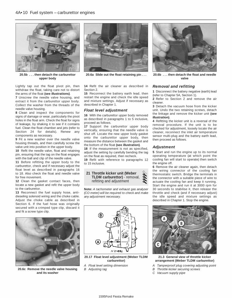
Lightly tap out the float pivot pin, thenwithdraw the float, taking care not to distortthe arms of the float (see illustrations).7 Unscrew the needle valve housing, andextract it from the carburettor upper body.Collect the washer from the threads of theneedle valve housing.8 Clean and inspect the components forsigns of damage or wear, particularly the pivotholes in the float arm. Check the float for signsof leakage, by shaking it to see if it containsfuel. Clean the float chamber and jets (refer toSection 24 for details). Renew anycomponents as necessary.9 Fit a new washer over the needle valvehousing threads, and then carefully screw thevalve unit into position in the upper body.10 Refit the needle valve, float and retainingpin, ensuring that the tag on the float engageswith the ball and clip of the needle valve.11 Before refitting the upper body to thecarburettor, check and if necessary adjust thefloat level as described in paragraphs 16 to 18. Also check the float and needle valvefor free movement.12 Clean the gasket contact faces, thenlocate a new gasket and refit the upper bodyto the carburettor.13 Reconnect the fuel supply hose, anti-dieseling solenoid wiring and the choke cable.Adjust the choke cable as described inSection 6. If the fuel hose was originallysecured with a crimped type clip, discard itand fit a screw type clip.
14 Refit the air cleaner as described inSection 2.15 Reconnect the battery earth lead, thenrestart the engine and check the idle speedand mixture settings. Adjust if necessary asdescribed in Chapter 1.
Float level adjustment16 With the carburettor upper body removedas described in paragraphs 1 to 5 inclusive,proceed as follows.17 Support the carburettor upper bodyvertically, ensuring that the needle valve isshut off. Locate the new upper body gasketonto the carburettor upper body, thenmeasure the distance between the gasket andthe bottom of the float (see illustration).18 If the measurement is not as specified,adjust the setting by carefully bending the tagon the float as required, then recheck.19 Refit with reference to paragraphs 12 to 15 inclusive.
21 Throttle kicker unit (WeberTLDM carburettor) - removal,refitting and adjustment
4Note: A tachometer and exhaust gas analyser(CO meter) will be required to check and makeany adjustment necessary.
Removal and refitting1 Disconnect the battery negative (earth) lead(refer to Chapter 5A, Section 1).2 Refer to Section 2 and remove the aircleaner.3 Detach the vacuum hose from the kickerunit. Undo the two retaining screws, detachthe linkage and remove the kicker unit (seeillustration).4 Refitting the kicker unit is a reversal of theremoval procedure. If the unit is to bechecked for adjustment, loosely locate the aircleaner, reconnect the inlet air temperaturesensor multi-plug and the battery earth lead,then proceed as follows.
Adjustment5 Start and run the engine up to its normaloperating temperature (at which point thecooling fan will start to operate) then switchthe engine off.6 Remove the air cleaner again, then detachthe wiring connector of the cooling fanthermostatic switch. Bridge the terminals inthe connector with a suitable piece of wire toactuate the cooling fan and keep it running.Start the engine and run it at 3000 rpm for 30 seconds to stabilise it, then release thethrottle and check (and if necessary adjust)the idle speed and mixture settings asdescribed in Chapter 1. Stop the engine.
4A•10 Fuel system – carburettor engines
21.3 General view of throttle kickerarrangement (Weber TLDM carburettor)
A Tamperproof plug covering adjusting pointB Throttle kicker securing screwsC Vacuum supply pipe
20.17 Float level adjustment (Weber TLDMcarburettor)
A Float level setting dimensionB Adjusting tag20.6c Remove the needle valve housing
and its washer
20.6b . . . then detach the float and needlevalve
20.6a Slide out the float retaining pin . . .20.5b . . . then detach the carburettorupper body
1595Ford Fiesta Remake

7 Detach the vacuum hose between thethrottle kicker and the inlet manifold at source(but not the vacuum supply to the ignitionmodule). Connect a new length of vacuumhose directly between the manifold and thekicker unit.8 Restart the engine and check the enginespeed. The throttle kicker should increase theengine speed above its normal idle. Check thespeed registered against the specified throttlekicker operating speed.9 If required, the throttle kicker speed can beadjusted by prising free the tamperproof plugand the adjustment screw turned asnecessary (see illustration 21.3).10 When the adjustment is complete, stopthe engine, fit a new tamperproof plug,disconnect the temporary vacuum hose(between the manifold and the kicker unit) andreconnect the original hose (between thecarburettor and the kicker unit).11 Remove the bridging wire, and reconnectthe cooling fan thermostatic switch multi-plug. Refit and secure the air cleaner, anddisconnect the tachometer and CO meter tocomplete.
22 Throttle kicker control solenoid(Weber TLDM carburettor) -removal and refitting
2Removal1 Disconnect the battery negative (earth) lead(refer to Chapter 5A, Section 1).2 Disconnect the multi-plug from the solenoid(see illustration).3 Remove both vacuum pipes, havinglabelled them for correct subsequent refitting.4 Remove the screw securing the solenoidand mounting bracket assembly to thebulkhead panel, then withdraw the assemblyfrom the vehicle.
Refitting5 Refitting is a reversal of the removalprocedure, ensuring that the locating lugsnaps into position and that the vacuum pipesare connected to their correct terminals.
23 Carburettor (Weber TLDM) -removal and refitting 4
Note: Refer to the warning note in Section 1before proceeding. New gaskets will berequired on refitting, and a tachometer and anexhaust gas analyser will be required oncompletion.
Removal1 Disconnect the battery negative (earth) lead(refer to Chapter 5A, Section 1).2 Remove the air cleaner as described inSection 2.3 Disconnect the accelerator cable from thecarburettor (Section 3). 4 Disconnect the choke cable from thecarburettor (Section 6).5 Disconnect the fuel hose from thecarburettor, and plug its end to prevent fuelspillage and the ingress of dirt. If a crimpedtype hose clip is fitted, cut it free, but takecare not to damage the hose. Crimped clipsmust be discarded and replaced with screwtype clips during refitting.6 Disconnect the wiring from the anti-dieseling solenoid.7 Unscrew and remove the four carburettor-to-manifold retaining Torx head screws, thencarefully lift the carburettor from the manifold(see illustration).
Refitting8 Clean the carburettor and manifold gasketmating faces.
9 Refit in the reverse order of removal. Fit anew gasket, and tighten the retaining screwssecurely. Ensure that the fuel supply hoseconnection to the carburettor is securely fitted, using a new screw typeretaining clip.10 Reconnect the accelerator cable, andadjust it as described in Section 3.11 Reconnect the choke cable, and adjust itas described in Section 6.12 Refer to Section 2 and refit the air cleaner.13 When the battery is reconnected, startand warm up the engine then check the idlespeed and mixture settings as described inChapter 1.
24 Carburettor (Weber TLDM) -dismantling, cleaning,inspection and reassembly
4Note: Refer to the warning note in Section 1before proceeding. Check parts avail-ability before dismantling. If possible, obtainan overhaul kit containing all the relevantgaskets, seals, etc, required for reassemblyprior to dismantling the carburettor.
Dismantling1 With the carburettor removed from thevehicle, prepare a clean, flat work surfaceprior to commencing dismantling. Thefollowing procedures may be used for partialor complete dismantling, as required.2 Clean the exterior of the carburettor, thenundo the two retaining screws and lift theupper carburettor body from the lower section(see illustration overleaf).3 Remove the float and needle valve from thecarburettor upper body, as described inSection 20.4 Unscrew and remove the anti-dieselingsolenoid from the upper body, but ensure that
Fuel system – carburettor engines 4A•11
23.7 Four Torx head screws (arrowed) secure the carburettor tothe inlet manifold (Weber TLDM carburettor)
22.2 Throttle kicker control solenoid
A Multi-plug B Vacuum pipes C Securing screw
4A
1595Ford Fiesta Remake

the seal washer is removed together with thevalve (see illustration).5 Undo the three screws securing the chokemechanism, and detach it (see illustration).6 Unscrew and remove the two air correctionjets from the underside of the upper body.Note the size and location of each, to ensurecorrect refitting.7 Invert the upper body so that the emulsiontubes can fall out of their apertures (above theair correction jets). Remove the emulsiontubes from their locations, again having notedthe size and location of each.8 Unscrew and remove the main jets, againhaving noted their fitted positions.9 Dismantle the carburettor lower (main) bodyas follows.10 Prise free the accelerator pump dischargetube, but take care not to damage it or thecarburettor body (see illustration).11 Undo the four screws securing theaccelerator pump; remove the cover, followedby the diaphragm and return spring (seeillustrations). The valve should come out onthe end of the return spring. Check that thevalve is complete and with its O-ring seal(where applicable).12 Undo the three retaining screws, andremove the power valve unit. Remove thecover and return spring, followed by thediaphragm.13 Where fitted, undo the retaining screwsand remove the throttle kicker unit from thelower (main) body.
4A•12 Fuel system – carburettor engines
24.11c . . . and the return spring and valveassembly
24.11b . . . followed by its diaphragm . . .24.11a Remove the accelerator pumpcover . . .
24.10 Carefully prising out the acceleratorpump discharge tube assembly
24.5 Undo the three screws securing thechoke mechanism (arrowed)
24.4 Withdrawing the anti-dieseling (fuelcut-off) solenoid
1595Ford Fiesta Remake
24.2 Exploded view of the carburettor (Weber TLDM)
A Anti-dieseling (fuel cut-off) solenoid
B Emulsion tubesC Air-correction jetsD Choke pull-down
diaphragm assemblyE Manual choke linkageF Needle valveG FloatH Fast-idle adjusting screwJ Idle speed adjusting
screwK Idle mixture adjusting
screwL Throttle platesM Power valve assemblyN Accelerator pump
assemblyP Throttle kicker (if fitted)Q Upper body gasketR Main jets

14 Prise free and remove the tamperproofseal, then unscrew and remove the idlemixture adjustment screw.15 Undo the retaining screws, and removethe throttle housing from the carburettor mainbody.
Cleaning and inspection16 Wash the carburettor components,drillings and passages with clean petrol, thenblow them dry using a low-pressure air line. Ahigh-pressure air line must not be applied tothe accelerator pump discharge assembly orthe pump supply valve, as they each contain arubber Vernay valve, and these can easily bedamaged under high pressure. Never use apiece of wire for cleaning purposes.17 Examine all of the carburettorcomponents for signs of damage or wear,paying particular attention to the diaphragms,throttle spindle and plates, needle valve andmixture screw; the power valve jet is adjacentto the primary main jet. Renew alldiaphragms, sealing washers and gaskets asa matter of course.
Reassembly18 Refit the throttle housing to thecarburettor main body (fitting a new gasket),and secure with its retaining screws.19 Refit the idle mixture adjustment screw.Make an initial adjustment by screwing it fullyin (but do not overtighten or screw it onto itsseat), then unscrew it two full turns.20 Where fitted, reassemble the throttlekicker, ensuring that its diaphragm lies flat,and that the relative position of the operatinglink to the kicker cover is correct.21 Fit the power valve, ensuring that itsdiaphragm lies flat and the vacuum gallery aligns with the diaphragm andhousing.22 Refit the accelerator pump. Take care notdamage the valve as it is inserted, and checkthat the O-ring seal is correctly located on theend of the valve. Check that the valve is nottrapped by the spring.23 Refit the accelerator pump discharge jet.Take care not to damage the valve and/or theO-ring seal, and ensure that they are correctlylocated.24 Commence reassembly of the upper bodyby inserting the emulsion tubes and the aircorrection jets into their respective ports (asnoted during removal).25 Screw the anti-dieseling solenoid intoposition. Ensure that the aluminium washer isfitted, and take care not to overtighten thevalve.26 Refit the needle valve and the float, andadjust the float setting as described in Sec-tion 20.27 Refit the choke control mechanism, andsecure with its three retaining screws.28 Locate a new gasket onto the matingface, then refit the carburettor upper body tothe main body. As they are reassembled, takecare not to snag the float on the carburettor
main body. Fit and tighten the retainingscrews to secure.29 On completion, refit the carburettor asdescribed in Section 23. Where applicable,check and adjust the throttle kicker setting(Section 21) after adjusting the idle speed andmixture settings.
25 Carburettor (Weber DFTM) -description
The carburettor operates in essentially thesame manner as TLDM instrument describedin Section 18, but the following featuresshould be noted.
A throttle kicker is fitted to both manualtransmission, and CTX automatic trans-mission models, the operation of the unit isdescribed in Section 18.
The secondary venturi (barrel) is vacuum-operated on manual transmission models. OnCTX automatic transmission equipped modelsit is operated sequentially.
A bleed back solenoid (if fitted) is used tocontrol the amount of fuel being delivered tothe venturi by the action of the acceleratorpump.
Idle speed and mixture adjustmentprocedures are described in Chapter 1, but itis important to note that accurate adjustmentscan only be made using the necessaryequipment.
26 Carburettor (Weber DFTM) -fast-idle speed adjustment 4
Refer to the procedure contained in Sec-tion 19, but note the following points:a) When removing the air cleaner, do not
disconnect the vacuum supply orcrankcase ventilation hoses; the aircleaner should be positioned clear of thecarburettor assembly.
b) The fast-idle adjusting screw is located on the side of the linkage (seeillustration).
27 Throttle kicker unit (WeberDFTM carburettor) - removal,refitting and adjustment 4
Refer to the procedure contained in Sec-tion 21.
28 Carburettor (Weber DFTM) -removal and refitting 4
Note: Refer to the warning note in Section 1before proceeding. New gaskets will berequired on refitting, and a tachometer and anexhaust gas analyser will be required oncompletion.
Removal1 Disconnect the battery negative (earth) lead(refer to Chapter 5A, Section 1).2 Remove the air cleaner as described inSection 2.3 Disconnect the choke cable from thecarburettor (Section 6).4 Carefully prise out the accelerator linkretaining clip, remove both securing bolts,then detach the cable and bracket assembly.Position the cable and bracket assembly clearof the carburettor.5 Disconnect the fuel feed hose at thecarburettor, and plug its end to avoid spillageand prevent dirt ingress. If a crimped typehose clip is fitted, cut this free taking care notto damage the hose.6 Disconnect all relevant vacuum pipes fromthe carburettor, having labelled them forsubsequent refitting.7 Disconnect the electrical lead from the anti-dieseling (fuel cut-off) solenoid, and the bleedback solenoid (if fitted).8 Remove the four nuts securing thecarburettor to the inlet manifold, thenwithdraw it from the vehicle.
Refitting9 Clean the carburettor and manifold gasketmating faces.10 Refit in the reverse order of removal. Fit anew gasket, and tighten the retaining screwssecurely. Ensure that the fuel supply hose connection to the carburettor is securely fitted, using a new screw typeretaining clip.11 Reconnect the choke cable, and adjust itas described in Section 6.12 Refer to Section 2 and refit the air cleaner.13 When the battery is reconnected, startand warm up the engine then check the idlespeed and mixture settings as described inChapter 1.
Fuel system – carburettor engines 4A•13
26.1 Manual choke fast-idle adjustment.Inset shows fast-idle adjusting screw
(Weber DFTM carburettor)
4A
1595Ford Fiesta Remake

29 Carburettor (Weber DFTM) -dismantling, cleaning,inspection and reassembly
4Note: Refer to the warning note in Section 1before proceeding. Check parts avail-ability before dismantling. If possible, obtainan overhaul kit containing all the relevantgaskets, seals, etc, required for reassemblyprior to dismantling the carburettor.
Dismantling1 With the carburettor removed from the
vehicle, prepare a clean, flat work surfaceprior to commencing dismantling. Thefollowing procedures may be used for partialor complete dismantling, as required.2 Clean the exterior of the carburettor anddetach all vacuum pipes (where applicable),having noted their fitted location for correctsubsequent reassembly.3 Remove the six screws securing thecarburettor upper body, and detach it.Discard the gasket (see illustration).4 Dismantle the carburettor upper body asdescribed in the following paragraphs.5 Remove the three screws securing the
choke pull-down diaphragm and detach it(see illustration).6 Unscrew the brass nut adjacent to the fuelfeed connection, and remove the fuel feedfilter.7 Tap out the float retaining pin, then detachthe float and needle valve.8 Unscrew and remove the needle valvehousing.9 Dismantle the carburettor main body asdescribed in the following paragraphs.10 Remove the main and idle jets, havingnoted the size and fitted location of each oneto ensure correct subsequent reassembly.Note that the main jets are a combinedassembly incorporating air correction jets andemulsion tubes. Carefully prise out theaccelerator pump discharge tube.11 Detach the throttle kicker and itsmounting bracket assembly.12 Remove the anti-dieseling (fuel cut-off)solenoid.13 Remove the four screws securing theaccelerator pump assembly, and dismantlethe assembly noting the fitment of itscomponents (see illustration).14 Disconnect the secondary barreldiaphragm operating rod by pulling the lowersection of rod downwards and twisting torelease it from its retaining socket. Remove itsfour cover retaining screws and dismantle theassembly (see illustration).15 Undo the three screws securing thepower valve assembly and remove itsdiaphragm (see illustration).
4A•14 Fuel system – carburettor engines
29.15 Exploded view of the power valveassembly (Weber DFTM carburettor)
A Vacuum gallery B Diaphragm
29.14 Exploded view of the secondarybarrel diaphragm assembly
A Diaphragm C Operating rodB Return spring
29.13 Accelerator pump renewal (Weber DFTM carburettor)
A Diaphragm B Housing (cover)
29.5 Choke pull-down assembly (A) andfuel feed filter housing (B) (Weber DFTM
carburettor)
29.3 Exploded view of the carburettor (Weber DFTM)
A Manual choke assemblyB Choke vacuum pull-downC Secondary idle jetD Secondary barrel
diaphragm assemblyE Idle speed adjusting
screw
F Idle mixture adjustingscrew
G Accelerator pumpassembly
H Throttle kickerJ Power valve diaphragmK Float
L Primary main jet combinedassembly
M Primary idle jetN Needle valveP Fuel feed filterQ Secondary main jet
combined assembly
1595Ford Fiesta Remake

16 Prise out the tamperproof seal coveringthe fuel mixture screw, then undo and removethe mixture screw.
Cleaning and inspection17 Wash the carburettor components,drillings and passages with clean petrol, thenblow them dry using a low-pressure air line. Ahigh-pressure air line must not be applied tothe accelerator pump discharge assembly orthe pump supply valve, as they each contain arubber Vernay valve, and these can easily bedamaged under high pressure. Never use apiece of wire for cleaning purposes.18 Examine all of the carburettorcomponents for signs of damage or wear,paying particular attention to the diaphragms,throttle spindle and plates, needle valve andmixture screw; the power valve jet is adjacentto the primary main jet. Renew alldiaphragms, sealing washers and gaskets asa matter of course.
Reassembly19 Refit the fuel mixture screw by fullywinding the screw in, then unwinding threeturns to give an approximate setting.20 Refit the power valve assembly ensuringthat the diaphragm lies flat, and that thevacuum gallery lines up correctly with thediaphragm and housing.21 Reassemble the secondary barreldiaphragm into its housing, ensuring that the diaphragm lies flat and that the vacuumgallery lines up with the diaphragm andhousing. Also, to assist with installation, donot reconnect its operating rod until the coverhas been secured.22 Refit the throttle kicker mounting bracket.23 Refit the anti-dieseling (fuel cut-off)solenoid, using a new sealing washer.24 Refit the accelerator pump assembly,ensuring that the diaphragm lies flat and is notkinked.25 Reassemble the throttle kicker, ensuringthat the diaphragm lies flat and that the
relative position of the diaphragm operatinglink to the throttle kicker cover is correct. Fullyattach the throttle kicker assembly.26 Refit the main and idle jets, makingreference to the notes taken duringdismantling to ensure correct fitted locations.27 Reassemble the carburettor upper bodyas described in the following paragraphs.28 Refit the needle valve housing (using anew washer if applicable).29 Refit the needle valve and float assembly,having ensured that the float tag locatesbelow the spring clip on the needle valve.Insert the float retaining pin to secure.30 Adjust the float level as follows. Ensuringthat a new gasket is fitted to the carburettorupper body, hold the upper body in thevertical position; the needle valve must beshut off. Measure the distance shown (seeillustration), and adjust by bending the floattag if the measurement is outside thespecification. Recheck the float leveladjustment after bending the float tag, asnecessary.31 Refit the choke pull-down diaphragm,ensuring that the diaphragm lies flat and thatthe vacuum gallery lines up correctly with thediaphragm and housing (see illustration).32 Adjust the choke pull-down as follows.Fully close the choke, then manually push thediaphragm operating rod up to its stop;measure the distance between thedowndraught side of the choke plate and theventuri, using a gauge rod or the shank of atwist drill bit (of known size). If themeasurement is outside specification, removethe tamperproof seal from the housing, andadjust the now revealed adjustment screwaccordingly. Fit a new tamperproof seal aftersuccessful adjustment.33 Refit the fuel feed filter, and secure withits brass nut and sealing washer.34 Refit the carburettor upper body to thecarburettor main body, ensuring that its newgasket seats correctly and that the float doesnot foul during assembly. Insert and tightenthe securing screws.
35 Reconnect any vacuum pipes removedduring dismantling (where applicable).36 On completion, refit the carburettor asdescribed in Section 28. Where applicable,check and adjust the throttle kicker setting(Section 27) after adjusting the idle speed andmixture settings.
30 Carburettor (Weber TLD) -description
This carburettor incorporates many of thefeatures of the TLDM type described inSection 18. The main differences are that athrottle kicker is not used, the secondaryventuri (barrel) is vacuum-operated, and that acoolant-heated automatic choke controlsystem is fitted.
The choke system is fully automatic. Whenthe engine is cold, the bi-metal spring whichcontrols the position of the choke plate is fullywound up, and holds the plate closed. As theengine warms up, the bi-metal spring isheated by the coolant and begins to unwind,thereby progressively opening the chokeplate. A vacuum-operated pull-downmechanism controls the choke plate undercertain operating conditions, and an internalfast-idle system is incorporated.
Idle speed and mixture adjustmentprocedures are described in Chapter 1, but itis important to note that accurate adjustmentscan only be made using the necessaryequipment.
31 Carburettor (Weber TLD) -fast-idle speed adjustment 4
Note: Before carrying out any carburettoradjustments, ensure that the spark plug gapsare set as specified, and that all electrical andvacuum connections are secure. To carry outchecks and adjustments, an accurate
Fuel system – carburettor engines 4A•15
29.31 Exploded view of the choke pull-down assembly (Weber DFTM carburettor)
A Housing B Diaphragm
29.30 Float level adjustment (Weber DFTMcarburettor)
A Float level setting dimensionB Adjusting tag
4A
1595Ford Fiesta Remake

tachometer and an exhaust gas analyser (COmeter) will be required.1 Check that the idle speed and mixturesettings are as specified (as described inChapter 1). These must be correct beforechecking/adjusting the fast-idle speed.2 Switch the engine off, then remove the aircleaner as described in Section 2.3 With the engine at its normal operatingtemperature and a tachometer connected inaccordance with its manufacturer’sinstructions, hold the throttle linkage partlyopen, then close the choke plate until the fast-idle adjusting screw aligns with the third(middle) step on the fast-idle cam (seeillustration). Release the throttle linkage sothat the fast-idle speed adjusting screw restson the cam. Release the choke plate. Thelinkage will hold it in the fast-idle speedsetting position, as long as the acceleratorpedal is not depressed.4 Without touching the accelerator pedal,start the engine and record the fast-idle speedachieved. If adjustment is required, turn thefast-idle speed adjusting screw until thespecified fast-idle speed is obtained.5 When the throttle linkage is opened, thechoke plate should return to its fully-openposition. If this does not happen, either the
engine is not at its normal operatingtemperature, or the automatic chokemechanism is faulty.6 Switch off the engine and disconnect thetachometer. Refit the air cleaner.
32 Needle valve and float (WeberTLD carburettor) - removal,refitting and adjustment
41 Refer to Section 20 and proceed asdescribed, noting the following difference.2 In paragraph 4, ignore the instruction todetach the choke cable (an automatic chokeis fitted to the TLD type carburettor). Instead,clamp the coolant supply and return hoseswhich lead to the automatic choke unit tominimise coolant loss, then ensure that thecooling system is not pressurised (seeChapter 1). Identify then detach both of thecoolant hoses at the automatic chokehousing. Catch any coolant spillage in asuitable container.
Warning: DO NOT attempt toremove the expansion tank fillercap, or to disturb any part of thecooling system, while it or the
engine is hot, as there is a very great riskof scalding. If the expansion tank filler capmust be removed before the engine andradiator have fully cooled down (eventhough this is not recommended) thepressure in the cooling system must firstbe released. Cover the cap with a thicklayer of cloth, to avoid scalding, and slowlyunscrew the filler cap until a hissing soundcan be heard. When the hissing hasstopped, showing that pressure isreleased, slowly unscrew the filler capfurther until it can be removed; if morehissing sounds are heard, wait until theyhave stopped before unscrewing the capcompletely. At all times, keep well awayfrom the filler opening.3 On completion, reconnect the hoses to theautomatic choke unit, and remove the clampsfrom the hoses. Check and top-up the coolantlevel on completion (see “Weekly Checks” andChapter 1).
33 Automatic choke (WeberTLD carburettor) - adjustment 3
1 Disconnect the battery negative (earth) lead(refer to Chapter 5A, Section 1).2 Remove the air cleaner as described inSection 2.3 Disconnect the coolant hoses to the chokeunit as described in paragraph 2 of theprevious Section.4 Note the position of the choke coil housingalignment marks, then undo the threeretaining screws and withdraw the automaticchoke bi-metal coil housing (see illustration).5 Remove the inner heat shield (seeillustration). To check and adjust the chokevacuum pull-down, secure the choke platelever in the closed position by fitting a rubberband, open the throttle to allow the chokeplate to fully close, then release the throttle.6 Using a screwdriver, push the operatingarm to the right against its spring, andmeasure the clearance between the loweredge of the choke plate and the venturi usinga twist drill or other suitable gauge rod (seeillustration). Where the clearance is outsidethat specified, remove the plug from thediaphragm housing, and turn the adjustingscrew (now exposed) in the required direction.7 Fit a new diaphragm housing plug andremove the rubber band.8 Refit the heat shield so that its slotted holeengages over the choke housing peg.9 Refit the bi-metal coil housing by firstconnecting the bi-metal spring to the chokelever (ensuring correct engagement), locatethe housing and hand-tighten the threeretaining screws. Rotate the housing to alignthe index line on the housing with the dotmark on the choke main body, then retightenthe retaining screws.10 Reconnect the coolant hoses withreference to paragraph 3 in the previousSection.11 Refit the air cleaner as described inSection 2.
4A•16 Fuel system – carburettor engines
33.6 Choke plate pull-down adjustment(Weber TLD carburettor)
A Twist drill C Adjusting screwB Diaphragm held fully open
33.5 Automatic choke internal heatshield(Weber TLD carburettor)
33.4 Automatic choke housing alignment(Weber TLD carburettor)
A Dot punch markB Choke housing alignment mark
1595Ford Fiesta Remake
31.3 Fast-idle speed adjustment (Weber TLD carburettor) (Housing cut
away for illustration clarity)
A Fast-idle camB Fast-idle speed adjusting screw on third
step of cam

34 Automatic choke (WeberTLD carburettor) - removal,inspection and refitting
4Note: Refer to the warning note in Section 1before proceeding. A new carburettor upperbody gasket will be required whenreassembling. On completion, a tachometerwill be required to check the fast-idle speedadjustment.
Removal1 Disconnect the battery negative (earth) lead(refer to Chapter 5A, Section 1).2 Remove the air cleaner as described inSection 2.3 To prevent excess coolant loss, clamp thecoolant supply and return hoses to theautomatic choke unit, and ensure that thecooling system is not pressurised (seeChapter 1). Identify then detach both of thecoolant hoses at the automatic chokehousing. Catch any coolant spillage in asuitable container.
Warning: DO NOT attempt toremove the expansion tank fillercap, or to disturb any part of thecooling system, while it or the
engine is hot, as there is a very great riskof scalding. If the expansion tank filler capmust be removed before the engine andradiator have fully cooled down (eventhough this is not recommended) thepressure in the cooling system must firstbe released. Cover the cap with a thicklayer of cloth, to avoid scalding, and slowlyunscrew the filler cap until a hissing soundcan be heard. When the hissing hasstopped, showing that pressure isreleased, slowly unscrew the filler capfurther until it can be removed; if morehissing sounds are heard, wait until theyhave stopped before unscrewing the capcompletely. At all times, keep well awayfrom the filler opening.4 Detach the fuel pipe and the anti-dieselingsolenoid wiring connector. Any crimped typehose clips must be replaced with a screwclamp type clips during reassembly.5 Unscrew and remove the retaining screws
(two conventional, and four Torx type), then liftthe carburettor upper body clear and remove it.6 Note the position of the choke housingalignment marks, then undo the three retainingscrews and remove the choke bi-metal coilunit. Remove the internal heat shield.7 To remove the automatic choke unit, undothe three retaining screws and detach thechoke link from the operating lever (seeillustration).8 Undo the three retaining screws to removethe vacuum diaphragm unit.9 If dismantling the choke mechanism anyfurther, note the component fitment as an aidto reassembly, but do not detach the chokespindle.
Inspection10 Clean and inspect all components forwear, damage and/or distortion. Payparticular attention to the condition of thevacuum (pull-down) diaphragm and the chokehousing O-ring. Renew any items that aredefective (or suspect).
Refitting11 Reassemble the automatic chokemechanism, making references to the notestaken during dismantling. Note that nolubricants must be used (see illustration).12 Refit the vacuum unit, making reference tothe notes taken during dismantling. Ensurethat the diaphragm is lying flat beforetightening the housing retaining screws.13 Locate the O-ring (ensuring that it iscorrectly seated), then reconnect the chokelink. Refit the automatic choke unit, and securewith the retaining screws. Check and adjustthe choke vacuum pull-down as described in the previous Section (paragraphs 5 and 6).14 Refit the inner heat shield, ensuring thatthe location peg is securely engaged in itsnotch.15 Refit the automatic choke housing and thebi-metal spring unit as described in theprevious Section (paragraph 9).16 Refit the carburettor upper body, ensuringthat a new gasket is used and that the matingsurfaces are clean. Fit the retaining screws tosecure.17 Reconnect the fuel hose to the carburettor,using new screw type hose clips to secure it.18 Reconnect the anti-dieseling solenoidwiring connector.19 Reconnect the coolant hoses to theautomatic choke unit, then check and if
necessary top-up the cooling system asdescribed in “Weekly Checks” and Chapter 1.20 Reconnect the battery negative lead, thencheck and adjust the fast-idle speed asdescribed in Section 31.21 Refit the air cleaner (Section 2).
35 Carburettor (Weber TLD) -removal and refitting 4
Note: Refer to the warning note in Section 1before proceeding. New gaskets will be requiredon refitting and a tachometer and an exhaust gasanalyser will be required on completion.
Removal1 Disconnect the battery negative (earth) lead(refer to Chapter 5A, Section 1).2 Remove the air cleaner as described inSection 2.3 Release any pressure remaining in thecooling system (see Chapter 1), and thendetach the two coolant hoses from theautomatic choke unit. Catch any coolantspillage in a suitable container. Identify eachhose for subsequent refitting, then plug theirends or position them as high as possible toprevent coolant leakage.
Warning: DO NOT attempt toremove the expansion tank fillercap, or to disturb any part of thecooling system, while it or the
engine is hot, as there is a very great risk ofscalding. If the expansion tank filler capmust be removed before the engine andradiator have fully cooled down (eventhough this is not recommended) thepressure in the cooling system must first bereleased. Cover the cap with a thick layer ofcloth, to avoid scalding, and slowly unscrewthe filler cap until a hissing sound can beheard. When the hissing has stopped,showing that pressure is released, slowlyunscrew the filler cap further until it can beremoved; if more hissing sounds are heard,wait until they have stopped beforeunscrewing the cap completely. At all times,keep well away from the filler opening.4 Disconnect the accelerator cable from thelinkage at the carburettor, as described inSection 3.5 Detach the anti-dieseling solenoid wiringconnector.6 Detach the fuel feed hose at the carburettor.
Fuel system – carburettor engines 4A•17
34.11 Exploded view of the automatic choke linkage (Weber TLD carburettor)
34.7 Automatic choke assembly (Weber TLD carburettor)
A Pull-down diaphragm housingB Securing screws
4A
1595Ford Fiesta Remake
A Operating link/fast-idle cam
B Fast-idle cam return springC Spindle sleeveD Connecting rod and lever
assemblyE Pull-down kinkF Actuating leverG Automatic choke housing

As it is detached, plug the end of the hose toprevent excessive fuel spillage and the ingressof dirt. Where a crimped type hose clip is fitted,cut it free, taking care not to damage the hose;a new screw type clip will need to be obtainedto replace the crimped clip during reassembly.7 Disconnect the relevant vacuum pipes fromthe carburettor. As they are detached, labelthem to ensure correct reassembly.8 Unscrew and remove the four Torx-typeretaining screws, and carefully lift clear thecarburettor from the inlet manifold (seeillustration). Remove the gasket.
Refitting9 Clean the carburettor and the inlet manifoldmating faces.10 Refit the carburettor in the reverse order ofremoval, ensuring that a new gasket is fitted.11 If they are perished or were damagedduring removal, renew the fuel and/or vacuumhoses.12 Reconnect the automatic choke unithoses, and then check/top-up the coolingsystem if required, as described in “WeeklyChecks” and Chapter 1.13 When the battery is reconnected, startand warm up the engine then check the idlespeed and mixture settings as described inChapter 1.
36 Carburettor (Weber TLD) -dismantling, cleaning,inspection and reassembly
4Proceed as described in Section 24, but
refer to the appropriate illustrations for theTLD carburettor (see illustrations). Thefollowing should also be observed:a) When refitting the idle mixture adjustment
screw, make the initial adjustment byscrewing it fully into position (withoutovertightening it), then unscrewing it bythree full turns.
b) Refer to Section 32 to adjust the needlevalve and float.
c) When the carburettor is reassembled andrefitted, check and adjust the idle speedand mixture settings as described inChapter 1.
37 Inlet manifold - removal and refitting 4
Note: Refer to the warning note in Section 1before proceeding.
Removal1 Drain the cooling system as described inChapter 1.2 Remove the carburettor as described in therelevant earlier Sections of this Chapter,according to carburettor type.3 Noting their locations, disconnect thecoolant, vacuum and breather hoses from themanifold.4 Disconnect the wiring multi-plugs from theengine sensors at the inlet manifold.Disconnect the radio earth lead at the inletmanifold connector.5 Undo the retaining bolts, and withdraw themanifold from the cylinder head. Remove thegasket.6 With the manifold removed, clean all tracesof the old gasket from the mating surfaces ofthe manifold and the cylinder head.
Refitting7 Refitting is the reversal of removal. Use anew gasket, and tighten the retaining bolts tothe specified torque. Refit the remainder of thecomponents with reference to the appropriateChapters of this manual. On completion, refill the cooling system as described inChapter 1.
36.1c Float level adjustment (Weber TLDcarburettor)
A Float level setting dimensionB Adjusting tag
36.1b Jet arrangement in carburettorupper body (Weber TLD carburettor)
A Primary air correction jetB Secondary air correction jetC Secondary main jetD Primary main jet
4A•18 Fuel system – carburettor engines
36.1a Exploded view of the carburettor (Weber TLD)
A Emulsion tubesB Air correction jetsC Automatic choke
assemblyD Choke pull-down
diaphragm
E Main jetsF Secondary barrel
diaphragm assemblyG Power valve diaphragmH Accelerator pump
diaphragm
J Idle mixture adjustingscrew
K Fuel feed filterL Needle valve assemblyM Anti-dieseling (fuel cut-off)
solenoid
35.8 General view of Weber TLDcarburettor
A Torx head screws securing carburettor toinlet manifold
B Standard screws securing upper body tomain body
1595Ford Fiesta Remake

4B
1595Ford Fiesta Remake
GeneralSystem type . . . . . . . . . . . . . . . . . . . . . . . . . . . . . . . . . . . . . . . . . . . . . . Central Fuel injection (CFi)Application . . . . . . . . . . . . . . . . . . . . . . . . . . . . . . . . . . . . . . . . . . . . . . . 1.1 and 1.3 litre HCS engines and 1.4 litre CVH engines
Fuel gradeFuel octane requirement . . . . . . . . . . . . . . . . . . . . . . . . . . . . . . . . . . . . . 95 RON unleaded
Fuel system dataRegulated fuel pressure - engine running at idle speed . . . . . . . . . . . . . 1.0 ± 0.1 barsHold pressure - engine stopped after 1 minute . . . . . . . . . . . . . . . . . . . 0.5 bars minimum
Torque wrench settings Nm lbf ftCFi unit-to-inlet manifold . . . . . . . . . . . . . . . . . . . . . . . . . . . . . . . . . . . . 12 to 15 9 to 11Inlet manifold . . . . . . . . . . . . . . . . . . . . . . . . . . . . . . . . . . . . . . . . . . . . . 16 to 20 12 to 15Inlet air temperature sensor . . . . . . . . . . . . . . . . . . . . . . . . . . . . . . . . . . 20 to 25 15 to 18Oxygen sensor . . . . . . . . . . . . . . . . . . . . . . . . . . . . . . . . . . . . . . . . . . . . 50 to 70 37 to 52
Chapter 4 Part B:Fuel system - central fuel injection engines
Accelerator cable - removal, refitting and adjustment . . . . . . . . . . . 5Accelerator pedal - removal and refitting . . . . . . . . . . . . . . . . . . . . . 6Air cleaner assembly and air inlet components - removal and
refitting . . . . . . . . . . . . . . . . . . . . . . . . . . . . . . . . . . . . . . . . . . . . . . 4Air cleaner element renewal . . . . . . . . . . . . . . . . . . . . . .See Chapter 1Fuel cut-off switch - removal and refitting . . . . . . . . . . . . . . . . . . . . 12Fuel filter renewal . . . . . . . . . . . . . . . . . . . . . . . . . . . . . . .See Chapter 1Fuel injection system - checking . . . . . . . . . . . . . . . . . . . . . . . . . . . . 13Fuel injection system components - removal and refitting . . . . . . . . 14Fuel lines and fittings - general information . . . . . . . . . . . . . . . . . . . 3Fuel pump/fuel gauge sender unit - removal and refitting . . . . . . . . 9
Fuel pump/fuel pressure - checking . . . . . . . . . . . . . . . . . . . . . . . . . 7Fuel system - depressurisation . . . . . . . . . . . . . . . . . . . . . . . . . . . . . 2Fuel tank - removal, inspection and refitting . . . . . . . . . . . . . . . . . . . 8Fuel tank filler pipe - removal and refitting . . . . . . . . . . . . . . . . . . . . 11Fuel tank ventilation tube - removal and refitting . . . . . . . . . . . . . . . 10General fuel system checks . . . . . . . . . . . . . . . . . . . . . .See Chapter 1General information and precautions . . . . . . . . . . . . . . . . . . . . . . . . 1Inlet manifold - removal and refitting . . . . . . . . . . . . . . . . . . . . . . . . 15Underbody fuel/brake line check . . . . . . . . . . . . . . . . . . .See Chapter 1Underbonnet check for fluid leaks and hose condition . .See Chapter 1
4B•1
Specifications
Contents
Easy, suitable fornovice with littleexperience
Fairly easy, suitablefor beginner withsome experience
Fairly difficult,suitable for competentDIY mechanic
Difficult, suitable forexperienced DIYmechanic
Very difficult,suitable for expert DIYor professional
Degrees of difficulty
54321

1 General information andprecautions
General informationThe fuel system consists of a fuel tank
(mounted under the body, beneath the rearseats), fuel hoses, an electric fuel pumpmounted in the fuel tank, and a central fuelinjection (CFi) system.
Fuel is supplied from the tank by an integralelectric fuel pump (and combined fuel gaugesender unit). The fuel is passed through an in-line filter within the engine compartment, thento the fuel injection unit. The fuel is maintainedat the required operating pressure by apressure regulator unit.
The CFi unit itself is a relatively simpledevice when compared with a conventionalcarburettor. Fuel is injected by a singlesolenoid valve (fuel injector) which is mountedcentrally on top of the unit. It is this featurewhich gives the system CFi (or Central Fuelinjection) its name (see illustration).
The injector is energised by an electricalsignal sent from the EEC IV enginemanagement module. When energised, theinjector pintle is lifted from its seat, andatomised fuel is delivered into the inletmanifold under pressure. The electricalsignals take two forms of current - a highcurrent to open the injector, and a low currentto hold it open for the duration required. Atidle speed, the injector is pulsed at everyother inlet stroke, rather than with everystroke as during normal operation.
The air-to-fuel mixture ratio is regulated bythe EEC IV module, based on inputs from thevarious engine sensors. No adjustments tothe fuel mixture are possible.
The throttle plate control motor (mountedon the side of the CFi unit) regulates the idlespeed by reacting to the signals sent by theEEC IV module. The signals are calculated bythe values and information provided from theengine sensors. When the throttle positionsensor indicates that the throttle is closed, themodule enters the idle speed mode ordashpot mode (according to engine speed).The module maintains the idle speed at a
constant value, making minor adjustments asnecessary for different loads and conditions.The base idle speed can only be adjusted by adealer or fuel injection specialist with thenecessary equipment to link up to the enginemanagement module.
To prevent the engine from running on (ordieseling) when it is switched off, the EEC IVmodule sends a signal to the throttle platecontrol motor, to fully close the throttle plateand return it to its preset position ready forrestarting. When the ignition is switched on to restart the engine, the motor repositionsthe throttle plate to the position requiredaccording to the prevailing conditions.
The EEC IV module is the heart of the entireengine management system, controlling thefuel injection, ignition and emissions controlsystems. The module receives informationfrom various sensors to determine enginetemperature, speed and load, and thequantity of air entering the engine. Thesensors also inform the module of throttleposition, inlet air temperature and exhaust gasoxygen content. All the information suppliedto the module is computed and comparedwith pre-set values stored in it’s memory, todetermine the required period of injection.
Information on crankshaft position andengine speed is generated by the distributoron pre-1990 CVH engine models, or by acrankshaft position sensor on all othermodels. The inductive head of the crankshaftposition sensor runs just above the engineflywheel and scans a series of 36 protrusionson the flywheel periphery. As the crankshaftrotates, the sensor transmits a pulse to thesystem’s ignition module every time aprotrusion passes it. There is one missingprotrusion in the flywheel periphery at a pointcorresponding to 90º BTDC. The ignitionmodule recognises the absence of a pulsefrom the crankshaft position sensor at thispoint to establish a reference mark forcrankshaft position. Similarly, the time intervalbetween absent pulses is used to determineengine speed. This information is then fed tothe EEC IV module for further processing.
Engine temperature information is suppliedby the coolant temperature sensor. Thiscomponent is an NTC (Negative TemperatureCoefficient) thermistor - that is, a semi-conductor whose electrical resistancedecreases as its temperature increases. Itprovides the EEC IV module with a constantly-varying (analogue) voltage signal,corresponding to the temperature of theengine coolant. This is used to refine thecalculations made by the module, whendetermining the correct amount of fuelrequired to achieve the ideal air/fuel mixtureratio.
Inlet air temperature information is suppliedby the inlet air temperature sensor. Thiscomponent is also an NTC thermistor - seethe previous paragraph - providing the EEC IVmodule with a signal corresponding to thetemperature of air passing into the engine.
4B•2 Fuel system - central fuel injection engines
1.3 Exploded view of the CFi unit
1 Fuel injector assembly2 Fuel pressure regulator
assembly
3 Fuel feed connector4 Intake air temperature
sensor
5 Throttle-plate controlmotor
6 Throttle position sensor7 Fuel injector wiring
1595Ford Fiesta Remake

This is used to refine the calculations made bythe module, when determining the correctamount of fuel required to achieve the idealair/fuel mixture ratio.
A throttle position sensor is mounted on theend of the throttle valve spindle, to providethe EEC IV module with a constantly-varying(analogue) voltage signal corresponding to thethrottle opening. This allows the module toregister the driver’s input when determiningthe amount of fuel required by the engine.
Road speed is monitored by the vehiclespeed sensor. This component is a Hall-effectgenerator, mounted on the transmission’sspeedometer drive. It supplies the EEC IVmodule with a series of pulses correspondingto the vehicle’s road speed, enabling themodule to control features such as the fuelshut-off on overrun.
A manifold absolute pressure sensormeasures inlet manifold vacuum, and suppliesthis information to the module for calculationof engine load at any given throttle position.
Where power steering is fitted, a pressure-operated switch is screwed into the powersteering system’s high-pressure pipe. Theswitch sends a signal to the EEC IV module toreduce engine speed should the powersteering fluid pressure become excessivelyhigh.
Certain later engines may be fitted with aheater in the inlet manifold. This is controlledby the EEC IV module to ensure that, evenbefore the effect of the coolant heatingbecomes apparent, the manifold is warmed-up. This prevents fuel droplets condensing inthe manifold, thus improving driveability andreducing exhaust emissions when the engineis cold.
The oxygen sensor in the exhaust systemprovides the EEC IV module with constantfeedback - “closed-loop” control - whichenables it to adjust the mixture to provide thebest possible conditions for the catalyticconverter to operate.
PrecautionsWarning: Petrol is extremelyflammable - great care must betaken when working on any partof the fuel system. Do not
smoke or allow any naked flames oruncovered light bulbs near the work area.Note that gas powered domesticappliances with pilot flames, such asheaters, boilers and tumble dryers, alsopresent a fire hazard - bear this in mind ifyou are working in an area where suchappliances are present. Always keep asuitable fire extinguisher close to the workarea and familiarise yourself with itsoperation before starting work. Wear eyeprotection when working on fuel systemsand wash off any fuel spilt on bare skinimmediately with soap and water. Notethat fuel vapour is just as dangerous asliquid fuel; a vessel that has just beenemptied of liquid fuel will still contain
vapour and can be potentially explosive.Petrol is a highly dangerous and volatileliquid, and the precautions necessarywhen handling it cannot be overstressed.
Many of the operations described in thisChapter involve the disconnection of fuellines, which may cause an amount of fuelspillage. Before commencing work, referto the above Warning and the informationin “Safety first” at the beginning of thismanual.
When working with fuel systemcomponents, pay particular attention tocleanliness - dirt entering the fuel systemmay cause blockages which will lead topoor running.
Note: Residual pressure will remain in the fuellines long after the vehicle was last used,when disconnecting any fuel line, it will benecessary to depressurise the fuel system asdescribed in Section 2.
2 Fuel system -depressurisation 1
Note: Refer to the warning note in Section 1before proceeding.
Warning: The followingprocedure will merely relieve thepressure in the fuel system -
remember that fuel will still be present inthe system components, and takeprecautions accordingly beforedisconnecting any of them.
1 The fuel system referred to in this Chapteris defined as the fuel tank and tank-mountedfuel pump/fuel gauge sender unit, the fuelfilter, the fuel injector, fuel pressure regulator,and the metal pipes and flexible hoses of thefuel lines between these components. Allthese contain fuel, which will be underpressure while the engine is running and/orwhile the ignition is switched on.2 The pressure will remain for some time afterthe ignition has been switched off, and mustbe relieved before any of these components isdisturbed for servicing work.3 The simplest depressurisation method is todisconnect the fuel pump electrical supply byremoving the fuel pump fuse (No 19) andstarting the engine; allow the engine to idleuntil it dies through lack of fuel pressure. Turnthe engine over once or twice on the starter toensure that all pressure is released, thenswitch off the ignition; do not forget to refit thefuse when work is complete. 4 Note that, once the fuel system has beendepressurised and drained (even partially), itwill take significantly longer to restart theengine - perhaps several seconds of cranking- before the system is refilled and pressurerestored.
3 Fuel lines and fittings -general information
Note: Refer to the warning note in Section 1before proceeding.
Disconnecting and connectingquick-release couplings1 Quick-release couplings are employed atmany of the unions in the fuel feed and returnlines.2 Before disconnecting any fuel systemcomponent, relieve the residual pressure inthe system (see Section 2), and equalise tankpressure by removing the fuel filler cap.
Warning: This procedure willmerely relieve the increasedpressure necessary for theengine to run - remember that
fuel will still be present in the systemcomponents, and take precautionsaccordingly before disconnecting any ofthem.
3 Release the protruding locking lugs on eachunion, by squeezing them together andcarefully pulling the coupling apart. Use rag tosoak up any spilt fuel. Where the unions arecolour-coded, the pipes cannot be confused.Where both unions are the same colour, notecarefully which pipe is connected to which,and ensure that they are correctlyreconnected on refitting.4 To reconnect one of these couplings, pressthem together until the locking lugs snap intotheir groove. Switch the ignition on and offfive times to pressurise the system, and checkfor any sign of fuel leakage around thedisturbed coupling before attempting to startthe engine.
Checking5 Checking procedures for the fuel lines areincluded in Chapter 1.
Component renewal6 If any damaged sections are to be renewed,use original-equipment replacement hoses orpipes, constructed from exactly the samematerial as the section being replaced. Do notinstall substitutes constructed from inferior orinappropriate material; this could cause a fuelleak or a fire.7 Before detaching or disconnecting any partof the fuel system, note the routing of allhoses and pipes, and the orientation of allclamps and clips. Replacement sections mustbe installed in exactly the same manner.8 Before disconnecting any part of the fuelsystem, be sure to relieve the fuel systempressure (see Section 2), and equalise tankpressure by removing the fuel filler cap. Alsodisconnect the battery negative (earth) lead -see Chapter 5A, Section 1. Cover the fittingbeing disconnected with a rag, to absorb anyfuel that may spray out.
Fuel system - central fuel injection engines 4B•3
4B
1595Ford Fiesta Remake
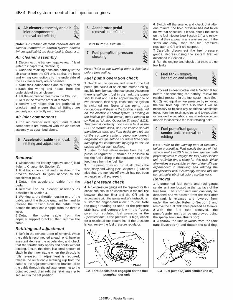
4 Air cleaner assembly and airinlet components - removal and refitting
1Note: Air cleaner element renewal and aircleaner temperature control system checks(where applicable) are described in Chapter 1.
Air cleaner assembly1 Disconnect the battery negative (earth) lead(refer to Chapter 5A, Section 1).2 Undo the retaining bolts and partially lift theair cleaner from the CFi unit, so that the hoseand wiring connections to the underside ofthe air cleaner body are accessible.3 Note their connections and routings, thendetach the wiring and hoses from theunderside of the air cleaner.4 Lift the air cleaner clear from the CFi unit.5 Refit in the reverse order of removal.6 Renew any hoses that are perished orcracked, and ensure that all fittings aresecurely and correctly reconnected.
Air inlet components7 The air cleaner inlet spout and relatedcomponents are removed with the air cleanerassembly as described above.
5 Accelerator cable - removal,refitting and adjustment 1
Removal1 Disconnect the battery negative (earth) lead(refer to Chapter 5A, Section 1).2 Fold back the carpet and insulation in thedriver’s footwell to gain access to theaccelerator pedal.3 Detach the accelerator cable from thepedal.4 Remove the air cleaner assembly asdescribed in Section 4.5 Working at the throttle housing end of thecable, pivot the throttle quadrant by hand torelease the tension from the cable, thendetach the inner cable nipple from the throttlelever.6 Detach the outer cable from theadjuster/support bracket, then remove thecable.
Refitting and adjustment7 Refit in the reverse order of removal. Whenthe cable is reconnected at each end, have anassistant depress the accelerator, and checkthat the throttle fully opens and shuts withoutbinding. Ensure that there is a small amount ofslack in the inner cable when the throttle isfully released. If adjustment is required,release the outer cable retaining clip from thecable at the adjustment/support bracket, slidethe cable through the adjuster grommet to thepoint required, then refit the retaining clip tosecure it in the set position.
6 Accelerator pedal - removal and refitting 1
Refer to Part A, Section 5.
7 Fuel pump/fuel pressure -checking 3
Note: Refer to the warning note in Section 1before proceeding.
Fuel pump operation check1 Switch on the ignition, and listen for the fuelpump (the sound of an electric motor running,audible from beneath the rear seats). Assumingthere is sufficient fuel in the tank, the pumpshould start and run for approximately one ortwo seconds, then stop, each time the ignitionis switched on. Note: If the pump runscontinuously all the time the ignition is switchedon, the electronic control system is running inthe backup (or “limp-home”) mode referred toby Ford as “Limited Operation Strategy” (LOS).This almost certainly indicates a fault in the EEC IV module itself, and the vehicle shouldtherefore be taken to a Ford dealer for a full testof the complete system, using the correctdiagnostic equipment; do not waste time or riskdamaging the components by trying to test thesystem without such facilities.2 Listen for fuel return noises from the fuelpressure regulator. It should be possible tofeel the fuel pulsing in the regulator and in thefeed hose from the fuel filter.3 If the pump does not run at all, check thefuse, relay and wiring (see Chapter 12). Checkalso that the fuel cut-off switch has not beenactivated and if so, reset it.
Fuel pressure check4 A fuel pressure gauge will be required for thischeck and should be connected in the fuel linebetween the fuel filter and the CFi unit, inaccordance with the gauge maker’s instructions.5 Start the engine and allow it to idle. Notethe gauge reading as soon as the pressurestabilises, and compare it with the figuresgiven for regulated fuel pressure in theSpecifications. If the pressure is high, checkfor a restricted fuel return line. If the pressureis low, renew the fuel pressure regulator.
6 Switch off the engine, and check that afterone minute, the hold pressure has not fallenbelow that specified. If it has, check the sealson the fuel injector (see Section 14) and renewthem if they appear in any way suspect. If theseals are okay, then the fuel pressureregulator or CFi unit are suspect.7 Carefully disconnect the fuel pressuregauge, depressurising the system first asdescribed in Section 2.8 Run the engine, and check that there are nofuel leaks.
8 Fuel tank - removal,inspection and refitting 3
Proceed as described in Part A, Section 8, butbefore disconnecting the battery, relieve theresidual pressure in the fuel system (see Sec-tion 2), and equalise tank pressure by removingthe fuel filler cap. Note also that it will benecessary to release any additional ventilationtubes from their retaining clips, and to repositionor remove the underbody heat shields on certainmodels for access to the tank retaining bolts.
9 Fuel pump/fuel gaugesender unit - removal andrefitting
3Note: Refer to the warning note in Section 1before proceeding. Ford specify the use of theirservice tool 23-026 (a large box spanner withprojecting teeth to engage the fuel pump/senderunit retaining ring’s slots) for this task. Whilealternatives are possible, in view of the difficultyexperienced in removing and refitting thepump/sender unit, it is strongly advised that thecorrect tool is obtained before starting work.
Removal1 A combined fuel pump and fuel gaugesender unit are located in the top face of thefuel tank. The combined unit can only bedetached and withdrawn from the tank afterthe tank is released and lowered from under the vehicle. Refer to Section 8 andremove the fuel tank, then proceed as follows.2 With the fuel tank removed, thepump/sender unit can be unscrewed usingthe special tool (see illustration).3 Withdraw the unit upwards from the tank(see illustration), and detach the seal ring.
9.3 Fuel pump (A) and sender unit (B)
4B•4 Fuel system - central fuel injection engines
9.2 Ford Special tool engaged on the fuelpump/sender unit
1595Ford Fiesta Remake

The seal ring must be renewed whenever thepump/sender unit is withdrawn from the tank.
Refitting4 Refit in the reverse order of removal. Lightlycoat the new unit seal ring with grease to easefitting, and ensure that the seal is notdistorted as the unit is fitted into position.Insert the unit so that the lug of the unit is inengagement with the slot in the tank aperture,then turn the unit to lock and secure.
10 Fuel tank ventilation tube -removal and refitting 3
Refer to Part A, Section 10, but note that onmodels with evaporative emission control, theventilation tube connects to the combinedroll-over/anti-trickle-fill valve assembly but,instead of venting to atmosphere, a furthertube runs the length of the vehicle to a carboncanister in the front right-hand corner of theengine compartment.
Further information on the evaporativeemission control system is contained in Part Eof this Chapter.
11 Fuel tank filler pipe - removal and refitting 3
Refer to Part A, Section 11.
12 Fuel cut-off switch -removal and refitting 2
Removal1 Disconnect the battery negative (earth) lead(refer to Chapter 5A, Section 1).2 Remove the left-hand sill scuff plate asdescribed in Chapter 11, Section 42.
3 Undo the retaining screws and withdraw thecut-off (inertia) switch and bracket assembly.As it is withdrawn, disconnect the wiring multi-plug from the switch (see illustrations).4 The switch may be separated from thebracket by removing the two securing screws.
Refitting5 Reconnect the wiring multi-plug to theswitch, ensuring that it is felt to snap securelyinto position.6 Refit the switch to the bracket then relocatethe bracket, and refit the screw to secure it.7 Reset the switch by pushing the top buttondown, then refit the sill scuff plate.8 Reconnect the battery and restart theengine to ensure that the switch has reset.
13 Fuel injection system -checking 3
Note: Refer to the warning note in Section 1before proceeding.
If a fault appears in the fuel injectionsystem, first ensure that all the system wiringconnectors are securely connected and freeof corrosion. Ensure that the fault is not due topoor maintenance; ie, check that the aircleaner filter element is clean, the spark plugsare in good condition and correctly gapped,the valve clearances are correctly adjusted(where adjustable), the cylinder compressionpressures are correct, the ignition timing iscorrect (where adjustable), and that theengine breather hoses are clear andundamaged, referring to Chapters 1, 2 and 5for further information.
If these checks fail to reveal the cause ofthe problem, the vehicle should be taken to asuitably-equipped Ford dealer for testing. Awiring block connector is incorporated in theengine management circuit, into which aspecial electronic diagnostic tester can beplugged. The tester will locate the fault quicklyand simply, alleviating the need to test all the
system components individually, which is atime-consuming operation that also carries arisk of damaging the EEC IV enginemanagement module.
14 Fuel injection systemcomponents - removal and refitting
3Note: Refer to the warning note in Section 1before proceeding.
Fuel injector1 Relieve the residual pressure in the fuelsystem (see Section 2), and equalise tankpressure by removing the fuel filler cap.
Warning: This procedure willmerely relieve the increasedpressure necessary for the engineto run - remember that fuel will
still be present in the system components,and take precautions accordingly beforedisconnecting any of them.2 Disconnect the battery negative (earth) lead(refer to Chapter 5A, Section 1).3 Refer to Section 4 and remove the aircleaner.4 Release the injector feed wiring multi-plug,and detach it from the injector (pulling on theplug - not the wire) (see illustration).
Fuel system - central fuel injection engines 4B•5
12.3b . . . and disconnect the multi-plug as it is withdrawn. Switchto bracket retaining screws (arrowed)
12.3a Remove the screw securing the inertia switch bracket . . .
14.4 Disconnect the multi-plug from theinjector
4B
1595Ford Fiesta Remake
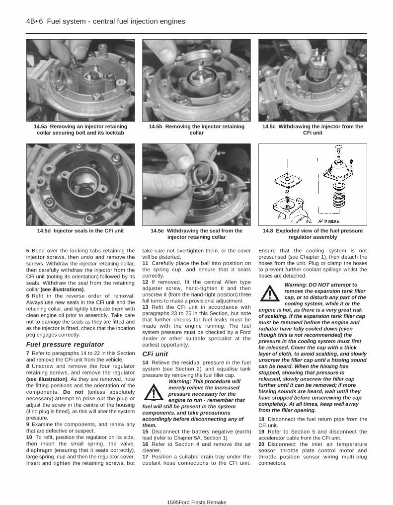
5 Bend over the locking tabs retaining theinjector screws, then undo and remove thescrews. Withdraw the injector retaining collar,then carefully withdraw the injector from theCFi unit (noting its orientation) followed by itsseals. Withdraw the seal from the retainingcollar (see illustrations).6 Refit in the reverse order of removal.Always use new seals in the CFi unit and theretaining collar, and lightly lubricate them withclean engine oil prior to assembly. Take carenot to damage the seals as they are fitted andas the injector is fitted, check that the locationpeg engages correctly.
Fuel pressure regulator7 Refer to paragraphs 14 to 22 in this Sectionand remove the CFi unit from the vehicle.8 Unscrew and remove the four regulatorretaining screws, and remove the regulator(see illustration). As they are removed, notethe fitting positions and the orientation of thecomponents. Do not (unless absolutelynecessary) attempt to prise out the plug oradjust the screw in the centre of the housing(if no plug is fitted), as this will alter the systempressure.9 Examine the components, and renew anythat are defective or suspect.10 To refit, position the regulator on its side,then insert the small spring, the valve,diaphragm (ensuring that it seats correctly),large spring, cup and then the regulator cover.Insert and tighten the retaining screws, but
take care not overtighten them, or the coverwill be distorted.11 Carefully place the ball into position onthe spring cup, and ensure that it seatscorrectly.12 If removed, fit the central Allen typeadjuster screw, hand-tighten it and thenunscrew it (from the hand-tight position) threefull turns to make a provisional adjustment.13 Refit the CFi unit in accordance withparagraphs 23 to 25 in this Section, but notethat further checks for fuel leaks must bemade with the engine running. The fuelsystem pressure must be checked by a Forddealer or other suitable specialist at theearliest opportunity.
CFi unit14 Relieve the residual pressure in the fuelsystem (see Section 2), and equalise tankpressure by removing the fuel filler cap.
Warning: This procedure willmerely relieve the increasedpressure necessary for theengine to run - remember that
fuel will still be present in the systemcomponents, and take precautionsaccordingly before disconnecting any ofthem.15 Disconnect the battery negative (earth)lead (refer to Chapter 5A, Section 1).16 Refer to Section 4 and remove the aircleaner.17 Position a suitable drain tray under thecoolant hose connections to the CFi unit.
Ensure that the cooling system is notpressurised (see Chapter 1), then detach thehoses from the unit. Plug or clamp the hosesto prevent further coolant spillage whilst thehoses are detached.
Warning: DO NOT attempt toremove the expansion tank fillercap, or to disturb any part of thecooling system, while it or the
engine is hot, as there is a very great riskof scalding. If the expansion tank filler capmust be removed before the engine andradiator have fully cooled down (eventhough this is not recommended) thepressure in the cooling system must firstbe released. Cover the cap with a thicklayer of cloth, to avoid scalding, and slowlyunscrew the filler cap until a hissing soundcan be heard. When the hissing hasstopped, showing that pressure isreleased, slowly unscrew the filler capfurther until it can be removed; if morehissing sounds are heard, wait until theyhave stopped before unscrewing the capcompletely. At all times, keep well awayfrom the filler opening.
18 Disconnect the fuel return pipe from theCFi unit.19 Refer to Section 5 and disconnect theaccelerator cable from the CFi unit.20 Disconnect the inlet air temperaturesensor, throttle plate control motor andthrottle position sensor wiring multi-plugconnectors.
4B•6 Fuel system - central fuel injection engines
14.8 Exploded view of the fuel pressureregulator assembly
14.5e Withdrawing the seal from theinjector retaining collar
14.5d Injector seals in the CFi unit
14.5c Withdrawing the injector from theCFi unit
14.5b Removing the injector retainingcollar
14.5a Removing an injector retainingcollar securing bolt and its locktab
1595Ford Fiesta Remake

21 Disconnect the vacuum hose from the CFiunit.22 Unscrew and remove the four retainingscrews, and remove the CFi unit from the inletmanifold (see illustration). Remove thegasket.23 Clean the CFi unit and the inlet manifoldmating faces.24 Refit in the reverse order of removal.Tighten the retaining bolts to the specifiedtorque wrench setting. Check and top-up thecooling system as required (see “WeeklyChecks” and Chapter 1).25 When the CFi unit is refitted, turn theignition on and off at least five times topressurise the system, and check for leaks.
Throttle plate control motor26 Disconnect the battery negative (earth)lead (refer to Chapter 5A, Section 1).27 Refer to Section 4 and remove the aircleaner.28 Detach the wiring multi-plugs from thethrottle position sensor and the throttle platecontrol motor, and release the retaining clipson the bracket (see illustrations).29 Undo and remove the motor supportbracket screws, and remove the bracketcomplete with the motor from the CFi unit(see illustration).30 Undo the motor retaining screws andremove it from the support bracket.31 Refit in the reverse order of removal, butnote the following points:
a) When refitting the motor and its supportbracket to the injector unit, the throttleposition sensor must locate on theaccelerator linkage, and the bracket mustalign with the pegs.
b) On completion, the idle speed should bechecked by a Ford dealer or fuel injectionspecialist who has the requiredequipment to link up with the EEC IVengine management module.
Fuel trap32 A fuel trap is fitted to the manifoldabsolute pressure sensor vacuum hose oncertain models.33 To remove the fuel trap, disconnect thevacuum hoses from the fuel trap and withdraw it.34 Refit in the reverse order of removal. It isimportant to ensure that the trap is correctlyorientated, with the “CARB” mark on one end
face towards the inlet manifold, and the“DIST” mark towards the MAP sensor (seeillustration).
EEC IV engine managementmoduleNote: The module is fragile. Take care not todrop it, or subject it to any other kind ofimpact. Do not subject it to extremes oftemperature, or allow it to get wet.35 Disconnect the battery negative (earth)lead (refer to Chapter 5A, Section 1).36 Unscrew and remove the two nutssecuring the module cover in the enginecompartment, then carefully draw the coveraway from its location. Unscrew the modulemulti-plug retaining bolt and disconnect themulti-plug from the module (see illustrations).37 The aid of an assistant will be required atthis stage, to support and withdraw the
Fuel system - central fuel injection engines 4B•7
14.28b Disconnecting the throttle platecontrol motor multi-plug
14.28a Release the throttle positionsensor multi-plug from its retaining clip
and disconnect it
14.22 CFi unit securing screws (arrowed)
14.36b Undoing the EEC IV enginemanagement module multi-plug retaining
bolt
14.34 Fuel trap vacuum connection markings14.29 Throttle-plate control motor and
throttle position sensor assemblymounting bracket securing screws
(arrowed)
14.36a Undoing the EEC IV enginemanagement module cover retaining nuts
(vehicle jack removed for clarity)
4B
1595Ford Fiesta Remake

module from inside the passengercompartment as its mounting bracketretaining tags are compressed and releasedfrom the engine compartment. Do not allowthe module to drop into the passengercompartment as irreparable damage is likelyto result (see illustration). The module maybe separated from its mounting bracket byundoing the securing bolts.38 Refitting is a reversal of the removalprocedure, ensuring that the modulemounting bracket retaining tags are felt tosnap into position
Crankshaft position sensor39 Refer to Chapter 5B.
Coolant temperature sensor40 Refer to Chapter 3.
Inlet air temperature sensor41 Remove the air cleaner assembly asdescribed in Section 4.42 Releasing its clip, unplug the sensor’selectrical connector, then unscrew the sensorfrom the CFi unit (see illustration).43 Refitting is the reverse of the removalprocedure. Tighten the sensor to the specifiedtorque wrench setting; if it is overtightened, itstapered thread may crack the resonator.
Throttle position sensor44 Remove the air cleaner assembly asdescribed in Section 4.45 Releasing its wire clip, unplug thesensor’s wiring connector. Remove theretaining screws, and withdraw the unit fromthe throttle plate control motor bracket (seeillustration). Do not force the sensor’s centreto rotate past its normal operating sweep; theunit will be seriously damaged.46 Refitting is the reverse of the removalprocedure, ensuring that the sensor actuatingarm is correctly located.
Vehicle speed sensor47 The sensor is mounted at the base of thespeedometer drive cable, and is removed withthe speedometer drive pinion. Refer to therelevant Section of Chapter 7A or B, asapplicable.
Manifold absolute pressuresensor48 The sensor is located near the centre ofthe engine compartment bulkhead.49 Disconnect the wiring multi-plug, anddetach the vacuum hose from the base of thesensor (see illustration).50 Undo the two retaining screws, andwithdraw the sensor from its location.
51 Refitting is the reverse of the removalprocedure.
Power steering pressure switch52 Releasing its clip, unplug the switch’selectrical connector, then unscrew the switchfrom the power steering high pressure pipe.Place a wad of rag underneath, to catch anyspilt fluid. If a sealing washer is fitted, renew itif it is worn or damaged.53 Refitting is the reverse of the removalprocedure; tighten the switch securely, thentop-up the fluid reservoir (see “WeeklyChecks”) to replace any fluid lost from thesystem, and bleed out any trapped air (seeChapter 10).
Oxygen sensorNote: The sensor is delicate, and will not workif it is dropped or knocked, if its power supplyis disrupted, or if any cleaning materials areused on it.54 Release the sensor’s electrical connectorfrom its bracket and unplug it to disconnectthe sensor (see illustration).55 Raise and support the front of the vehicleif required to remove the sensor fromunderneath (“see Jacking and vehiclesupport”). Remove the sensor heat shield thenunscrew the sensor from the exhaust systemfront downpipe; collect the sealing washer(where fitted).56 On refitting, clean the sealing washer(where fitted) and renew it if it is damaged or
4B•8 Fuel system - central fuel injection engines
14.54 Oxygen sensor (A) (shown with itsheatshield removed), and its multi-plug (B)
14.49 Manifold absolute pressure sensor location
A Securing screws B Multi-plug C Vacuum hoseArrows indicate ignition module retaining screws
14.45 Throttle position sensor retainingscrews (arrowed) (shown with throttle
plate control motor removed)
14.42 Disconnecting the intake airtemperature sensor multi-plug
1595Ford Fiesta Remake
14.37 Withdrawing the EEC IV enginemanagement module into the passenger
footwell

worn. Apply a smear of anti-seize compoundto the sensor’s threads, to prevent them fromwelding themselves to the downpipe inservice. Refit the sensor, tightening it to itsspecified torque wrench setting; a slottedsocket will be required to do this. Reconnectthe wiring, and heat shield then refit theconnector plug.
Inlet manifold heater57 The heater is located in a recess in theinlet manifold, directly underneath the CFiunit. While access is possible fromunderneath, it is preferable, depending on thetools available, to remove the completemanifold (Section 15) to reach the heater.58 Assuming the work is being carried outwithout removing the manifold, disconnectthe battery negative (earth) lead (refer toChapter 5A, Section 1).59 Chock the rear wheels then jack up thefront of the car and support it on axle stands(see “Jacking and vehicle support”).60 Disconnect the heater wiring, and extractthe circlip retaining the heater (seeillustration). Withdraw the heater.61 Refitting is the reverse of the removalprocedure. Ensure that both the heater and itscirclip are correctly located in the manifold.
Injector ballast resistor62 When fitted, this component is located onthe engine compartment bulkhead, next to themanifold absolute pressure sensor.63 Disconnect the battery negative (earth)lead (refer to Chapter 5A, Section 1).64 Disconnect the resistor wiring at its multi-plug, remove the retaining screw andwithdraw the resistor.65 Refitting is the reverse of the removalprocedure.
15 Inlet manifold - removal and refitting 3
Note: Refer to the warning note in Section 1before proceeding.
Removal1 Drain the cooling system as described inChapter 1.2 Remove the CFi unit as described inSection 14.3 Noting their locations, disconnect thecoolant, vacuum and breather hoses from themanifold.4 Disconnect the wiring multi-plugs from the
engine sensors at the inlet manifold.Disconnect the radio earth lead at the inletmanifold connector.5 Undo the retaining bolts, and withdraw themanifold from the cylinder head. Remove thegasket.6 With the manifold removed, clean all tracesof the old gasket from the mating surfaces ofthe manifold and the cylinder head.
Refitting7 Refitting is the reversal of removal. Use anew gasket, and tighten the retaining bolts tothe specified torque. Refit the remainder ofthe components with reference to theappropriate Chapters of this manual.
Fuel system - central fuel injection engines 4B•9
14.60 Inlet manifold heater components
4B
1595Ford Fiesta Remake

4B•10 Fuel system - central fuel injection engines
1595Ford Fiesta Remake
Notes

4C
1595Ford Fiesta Remake
GeneralSystem type . . . . . . . . . . . . . . . . . . . . . . . . . . . . . . . . . . . . . . . . . . . . . . Electronic Fuel injection (EFi) with turbocharger on RS Turbo modelsApplication . . . . . . . . . . . . . . . . . . . . . . . . . . . . . . . . . . . . . . . . . . . . . . . 1.6 litre CVH engines
Fuel gradeFuel octane requirement:
Engines without catalytic converter* . . . . . . . . . . . . . . . . . . . . . . . . . . 95 RON unleaded or 97 RON leadedEngines with catalytic converter . . . . . . . . . . . . . . . . . . . . . . . . . . . . . 95 RON unleaded (leaded fuel must not be used)
*Refer to dealer for latest recommendations
Fuel system dataIdle speed and mixture settings . . . . . . . . . . . . . . . . . . . . . . . . . . . . . . . See Chapter 1Fuel pump pressure - engine not running . . . . . . . . . . . . . . . . . . . . . . . 3.0 bars minimumRegulated fuel pressure - engine running at idle speed . . . . . . . . . . . . . 2.3 to 2.5 barsHold pressure - engine stopped after two minutes . . . . . . . . . . . . . . . . Not less than 0.8 bars below regulated pressure
TurbochargerType . . . . . . . . . . . . . . . . . . . . . . . . . . . . . . . . . . . . . . . . . . . . . . . . . . . . Garrett AiResearch T02Boost pressure . . . . . . . . . . . . . . . . . . . . . . . . . . . . . . . . . . . . . . . . . . . . 0.47 to 0.51 bars
Chapter 4 Part C:Fuel system - electronic fuel injection engines
Accelerator cable - removal, refitting and adjustment . . . . . . . . . . . 5Accelerator pedal - removal and refitting . . . . . . . . . . . . . . . . . . . . . 6Air cleaner assembly and air inlet components - removal and
refitting . . . . . . . . . . . . . . . . . . . . . . . . . . . . . . . . . . . . . . . . . . . . . . 4Air cleaner element renewal . . . . . . . . . . . . . . . . . . . . . .See Chapter 1Exhaust system check . . . . . . . . . . . . . . . . . . . . . . . . . . .See Chapter 1Fuel cut-off switch - removal and refitting . . . . . . . . . . . . . . . . . . . . 12Fuel filter renewal . . . . . . . . . . . . . . . . . . . . . . . . . . . . . . .See Chapter 1Fuel injection system - checking . . . . . . . . . . . . . . . . . . . . . . . . . . . . 13Fuel injection system components - removal and refitting . . . . . . . . 14Fuel lines and fittings - general information . . . . . . . . . . . . . . . . . . . 3Fuel pump/fuel gauge sender unit - removal and refitting . . . . . . . . 9Fuel pump/fuel pressure - checking . . . . . . . . . . . . . . . . . . . . . . . . . 7Fuel system - depressurisation . . . . . . . . . . . . . . . . . . . . . . . . . . . . . 2Fuel tank - removal, inspection and refitting . . . . . . . . . . . . . . . . . . . 8
Fuel tank filler pipe - removal and refitting . . . . . . . . . . . . . . . . . . . . 11Fuel tank ventilation tube - removal and refitting . . . . . . . . . . . . . . . 10General fuel system checks . . . . . . . . . . . . . . . . . . . . . .See Chapter 1General information and precautions . . . . . . . . . . . . . . . . . . . . . . . . 1Idle speed and mixture check and adjustment . . . . . . . .See Chapter 1Idle speed control valve cleaning and maintenance . . . .See Chapter 1Inlet manifold - removal and refitting . . . . . . . . . . . . . . . . . . . . . . . . 15Intercooler - removal and refitting . . . . . . . . . . . . . . . . . . . . . . . . . . . 17Turbocharger - general information and precautions . . . . . . . . . . . . 16Turbocharger - removal, examination and refitting . . . . . . . . . . . . . . 20Turbocharger boost control valve - removal and refitting . . . . . . . . . 18Turbocharger boost pressure - checking and adjustment . . . . . . . . 19Underbody fuel/brake line check . . . . . . . . . . . . . . . . . . .See Chapter 1Underbonnet check for fluid leaks and hose condition . .See Chapter 1
4C•1
Specifications
Contents
Easy, suitable fornovice with littleexperience
Fairly easy, suitablefor beginner withsome experience
Fairly difficult,suitable for competentDIY mechanic
Difficult, suitable forexperienced DIYmechanic
Very difficult,suitable for expert DIYor professional
Degrees of difficulty
54321

Torque wrench settings Nm lbf ftIdle speed control valve bolts . . . . . . . . . . . . . . . . . . . . . . . . . . . . . . . . . 4 to 5 3 to 4Fuel pressure regulator bolts . . . . . . . . . . . . . . . . . . . . . . . . . . . . . . . . . 8 to 12 6 to 9Fuel rail bolts . . . . . . . . . . . . . . . . . . . . . . . . . . . . . . . . . . . . . . . . . . . . . 20 to 26 15 to 19Inlet air temperature sensor . . . . . . . . . . . . . . . . . . . . . . . . . . . . . . . . . . 20 to 25 15 to 18Inlet manifold . . . . . . . . . . . . . . . . . . . . . . . . . . . . . . . . . . . . . . . . . . . . . 16 to 20 12 to 15Oxygen sensor . . . . . . . . . . . . . . . . . . . . . . . . . . . . . . . . . . . . . . . . . . . . 50 to 70 37 to 52Intercooler-to-radiator bolts . . . . . . . . . . . . . . . . . . . . . . . . . . . . . . . . . . 4 to 6 3 to 5Boost control valve screws . . . . . . . . . . . . . . . . . . . . . . . . . . . . . . . . . . . 2.2 to 2.7 1.5 to 2Exhaust manifold heatshield bolts . . . . . . . . . . . . . . . . . . . . . . . . . . . . . 21 to 26 16 to 19Exhaust manifold-to-engine nuts (non-Turbo models) . . . . . . . . . . . . . . 14 to 17 11 to 13Exhaust manifold-to-engine nuts (Turbo models) . . . . . . . . . . . . . . . . . 28 to 31 21 to 23Exhaust manifold-to-turbocharger bolts . . . . . . . . . . . . . . . . . . . . . . . . 20 to 28 15 to 21Turbocharger-to-exhaust downpipe nuts . . . . . . . . . . . . . . . . . . . . . . . . 35 to 47 26 to 35Turbocharger cooling pipe banjo union bolts . . . . . . . . . . . . . . . . . . . . . 22 to 29 17 to 22Turbocharger oil feed and return line couplings . . . . . . . . . . . . . . . . . . . 15 to 20 11 to 15
4C•2 Fuel system - electronic fuel injection engines
1595Ford Fiesta Remake
1 General information andprecautions
General informationThe fuel system consists of a fuel tank
(mounted under the body, beneath the rearseats), fuel hoses, an electric fuel pumpmounted in the fuel tank, and an electronicfuel injection system.
Fuel is supplied under pressure from thefuel pump to the fuel distributor rail mountedon top of the inlet manifold (see illustration).The fuel rail acts as a pressurised fuelreservoir for the fuel injectors. The electro-mechanical injectors have only “on” or “off”positions, the volume of fuel being injected to
meet the engine operating conditions beingdetermined by the length of time that theinjectors are opened. The volume of fuelrequired for one power stroke is determinedby the EEC IV engine management module,and is divided by two equal amounts. The firsthalf of the required volume is injected into thestatic air ahead of the inlet valve one completeengine revolution before the inlet valve is dueto open. After one further revolution, the inletvalve opens and the required fuel volume isinjected into the air flow being drawn into thecylinder. The fuel will therefore be consistentlyinjected to two inlet valves simultaneously at aparticular crankshaft position.
The volume of air drawn into the engine isgoverned by the air filter unit and othervariable operating factors. These variables areassessed by the EEC IV module and the
corresponding signals are produced toactuate the injectors accordingly.
The engine base idle speed can beadjusted (if required), by turning the adjusterscrew (covered by a tamperproof cap) in thethrottle housing. Provision for adjusting thefuel mixture is made by the mixture screw inthe potentiometer unit mounted on thebulkhead.
An idle speed control valve, itself controlledby the EEC-IV engine management module,stabilises the engine idle speed under allconditions by the opening of an auxiliary airpassage which bypasses the throttle. Apartfrom a base-idle speed adjustment, noadjustments to the operational idle speed canbe made.
The EEC IV module is the heart of the entireengine management system, controlling thefuel injection, ignition and emissions controlsystems. The module receives informationfrom various sensors to determine enginetemperature, speed and load, and thequantity of air entering the engine. Thesensors also inform the module of throttleposition, inlet air temperature and, on modelswith catalytic converters, exhaust gas oxygencontent. All the information supplied to themodule is computed and compared withpre-set values stored in it’s memory, todetermine the required period of injection.
Information on crankshaft position andengine speed is generated by a crankshaftposition sensor. The inductive head of thesensor runs just above the engine flywheeland scans a series of 36 protrusions on theflywheel periphery. As the crankshaft rotates, the sensor transmits a pulse to thesystem’s ignition module every time aprotrusion passes it. There is one missingprotrusion in the flywheel periphery at a pointcorresponding to 90° BTDC. The ignitionmodule recognises the absence of a pulsefrom the crankshaft position sensor at thispoint to establish a reference mark forcrankshaft position. Similarly, the time intervalbetween absent pulses is used to determineengine speed. This information is then fed tothe EEC IV module for further processing.
1.2 General view of the 1.6 litre EFi fuel injection system arrangement
1 Throttle housing2 Upper inlet manifold section3 Wiring loom connector4 Intake air temperature
sensor
5 Wiring harness ducting6 Fuel rail7 Lower section of inlet
manifold8 Cylinder head
9 Fuel injector10 Fuel pressure regulator11 Vacuum hose12 Air inlet duct

Engine temperature information is suppliedby the coolant temperature sensor. Thiscomponent is an NTC (Negative TemperatureCoefficient) thermistor - that is, a semi-conductor whose electrical resistancedecreases as its temperature increases. Itprovides the EEC IV module with a constantly-varying (analogue) voltage signal, corre-sponding to the temperature of the enginecoolant. This is used to refine the calculationsmade by the module, when determining thecorrect amount of fuel required to achieve theideal air/fuel mixture ratio.
Inlet air temperature information is suppliedby the inlet air temperature sensor. Thiscomponent is also an NTC thermistor - see theprevious paragraph - providing the module witha signal corresponding to the temperature of airpassing into the engine. This is used to refinethe calculations made by the module, whendetermining the correct amount of fuel requiredto achieve the ideal air/fuel mixture ratio.
A throttle position sensor is mounted on theend of the throttle valve spindle, to providethe EEC IV module with a constantly-varying(analogue) voltage signal corresponding to thethrottle opening. This allows the module toregister the driver’s input when determiningthe amount of fuel required by the engine.
Road speed is monitored by the vehiclespeed sensor. This component is a Hall-effectgenerator, mounted on the transmission’sspeedometer drive. It supplies the module with aseries of pulses corresponding to the vehicle’sroad speed, enabling the module to controlfeatures such as the fuel shut-off on overrun.
A manifold absolute pressure sensormeasures inlet manifold vacuum, and suppliesthis information to the EEC IV module forcalculation of engine load at any given throttleposition.
Where power steering is fitted, a pressure-operated switch is screwed into the powersteering system’s high-pressure pipe. Theswitch sends a signal to the EEC IV module toreduce engine speed should the power steeringfluid pressure become excessively high.
On models with a catalytic converter, theoxygen sensor in the exhaust system providesthe EEC IV module with constant feedback -“closed-loop” control - which enables it toadjust the mixture to provide the best possibleconditions for the catalytic converter to operate.
On turbocharged engines, control of theturbocharger boost pressure is also governedby the EEC IV module, acting through theboost control valve. This allows inlet manifolddepression to be applied to the turbochargerwastegate control.
The turbocharger consists of a turbine thatis driven by the exhaust gases, to suck airthrough the air filter and to compress it into theengine. An air-cooled intercooler, mountednext to the radiator, cools the inlet air (heatedby its passage through the turbocharger); thisincreases the density of the compressedfuel/air mixture entering the engine, thusimproving the engine’s power output.
PrecautionsWarning: Petrol is extremelyflammable - great care must betaken when working on any partof the fuel system. Do not
smoke or allow any naked flames oruncovered light bulbs near the work area.Note that gas powered domesticappliances with pilot flames, such asheaters, boilers and tumble dryers, alsopresent a fire hazard - bear this in mind ifyou are working in an area where suchappliances are present. Always keep asuitable fire extinguisher close to the workarea and familiarise yourself with itsoperation before starting work. Wear eyeprotection when working on fuel systemsand wash off any fuel spilt on bare skinimmediately with soap and water. Notethat fuel vapour is just as dangerous asliquid fuel; a vessel that has just beenemptied of liquid fuel will still containvapour and can be potentially explosive.Petrol is a highly dangerous and volatileliquid, and the precautions necessarywhen handling it cannot be overstressed.
Many of the operations described in thisChapter involve the disconnection of fuellines, which may cause an amount of fuelspillage. Before commencing work, referto the above Warning and the informationin “Safety first” at the beginning of thismanual.
When working with fuel systemcomponents, pay particular attention tocleanliness - dirt entering the fuel systemmay cause blockages which will lead topoor running.Note: Residual pressure will remain in the fuellines long after the vehicle was last used,when disconnecting any fuel line, it will benecessary to depressurise the fuel system asdescribed in Section 2.Note: Refer to Section 16 for specificprecautions relating to turbocharged engines.
2 Fuel system -depressurisation 1
Refer to Part B, Section 2.
3 Fuel lines and fittings -general information
Refer to Part B, Section 3.
4 Air cleaner assembly and airinlet components - removaland refitting
1Note: Air cleaner element renewal and aircleaner temperature control system checks(where applicable) are described in Chapter 1.
Air cleaner assembly1 Disconnect the battery negative (earth) lead(refer to Chapter 5A, Section 1).2 If the idle speed control valve is mountedon the air cleaner, disconnect the multi-plugand the air bypass hose from the valve.3 Disconnect the flexible hose between theair cleaner lid and the air inlet duct orturbocharger air inlet.4 Disconnect the crankcase breather hosefrom the front of the air cleaner housing.5 Unclip and remove the air cleaner lid, thenwithdraw the element.6 Remove the two bolts securing the forwardend of the air cleaner housing, free therearward end of the housing from its locationand carefully withdraw from the vehicle (seeillustration).7 Refitting is a reversal of the removalprocedure.
Air inlet components8 Disconnect the battery negative (earth) lead(refer to Chapter 5A, Section 1).9 If the idle speed control valve is mountedon the air cleaner, disconnect the multi-plugand the air bypass hose from the valve (seeillustration).10 Disconnect the HT leads from the sparkplugs, labelling them if necessary to avoidconfusion on refitting.
Fuel system - electronic fuel injection engines 4C•3
4.9 General view of the air inletcomponents on non-Turbo models
A Air inlet ductB Air inlet duct securing boltsC Spark plug HT lead connectorsD Air cleaner lidE Idle speed control valve multi-plugF Air bypass hose
4.6 Air cleaner housing attachments
A Bolts B Grommet
4C
1595Ford Fiesta Remake

11 On non-Turbo models, disconnect theflexible hose between the air cleaner lid andthe air inlet duct.12 On Turbo models, disconnect the idlespeed control valve air bypass hose from theair inlet duct and the flexible hose betweenthe air inlet duct and intercooler (seeillustration).13 Undo the two retaining bolts, and removethe air inlet duct from the rocker cover.14 Refitting is the reverse of the removalprocedure.
5 Accelerator cable - removal,refitting and adjustment 1
Removal1 Disconnect the battery negative (earth) lead(refer to Chapter 5A, Section 1).2 Remove the air inlet components asdescribed in Section 4.3 Fold back the carpet and insulation in thedriver’s footwell to gain access to theaccelerator pedal.4 Detach the accelerator cable from thepedal.5 Working at the throttle housing end of thecable, pivot the throttle quadrant by hand torelease the tension from the cable, thendetach the inner cable nipple from the throttlelever (see illustration).6 Detach the outer cable from theadjuster/support bracket, then remove thecable.
Refitting and adjustment7 Refit in the reverse order of removal. Whenthe cable is reconnected at each end, have an
assistant depress the accelerator, and checkthat the throttle fully opens and shuts withoutbinding. Ensure that there is a small amount ofslack in the inner cable when the throttle isfully released. If adjustment is required,release the outer cable retaining clip from thecable at the adjustment/support bracket, slidethe cable through the adjuster grommet to thepoint required, then refit the retaining clip tosecure it in the set position.
6 Accelerator pedal -removal and refitting 1
Refer to Part A, Section 5.
7 Fuel pump/fuel pressure -checking 3
Note: Refer to the warning note in Section 1before proceeding.
Fuel pump operation check1 Switch on the ignition, and listen for the fuelpump (the sound of an electric motor running,audible from beneath the rear seats). Assumingthere is sufficient fuel in the tank, the pumpshould start and run for approximately one ortwo seconds, then stop, each time the ignitionis switched on. Note: If the pump runscontinuously all the time the ignition is switchedon, the electronic control system is running inthe backup (or “limp-home”) mode referred toby Ford as “Limited Operation Strategy” (LOS).This almost certainly indicates a fault in the EEC IV module itself, and the vehicle shouldtherefore be taken to a Ford dealer for a full test
of the complete system, using the correctdiagnostic equipment; do not waste time or riskdamaging the components by trying to test thesystem without such facilities.2 Listen for fuel return noises from the fuelpressure regulator. It should be possible tofeel the fuel pulsing in the regulator and in thefeed hose from the fuel filter.3 If the pump does not run at all, check thefuse, relay and wiring (see Chapter 12). Checkalso that the fuel cut-off switch has not beenactivated and if so, reset it.
Fuel pressure check4 A fuel pressure gauge will be required forthis check and should be connected in thefuel line between the fuel filter and the fuel rail,in accordance with the gauge maker’sinstructions.5 Disconnect the wiring from the E-DISignition coil and the fuel injectors.6 Switch the ignition on and off twice, andcheck that the pump pressure is as listed inthe Specifications.7 If the pressure is not as specified, check thefuel system for leaks or damage. If the systemappears okay, renew the fuel pump.8 Reconnect the wiring to the ignition coil andfuel injectors.9 If the pump pressure was satisfactory, startthe engine and allow it to idle. Disconnect thevacuum hose at the fuel pressure regulator,and plug the hose. Note the gauge reading assoon as the pressure stabilises, and compareit with the figures given for regulated fuelpressure in the Specifications.10 If the regulated fuel pressure is not asspecified, remove the plug from the top of thefuel pressure regulator, and using a suitableAllen key, adjust the pressure regulator asnecessary.11 Switch off the engine, and check that thefuel pressure stays at the specified holdpressure for two minutes after the engine isturned off.12 Carefully disconnect the fuel pressuregauge, depressurising the system first asdescribed in Section 2. Reconnect the ignitioncoil and fuel injector wiring.13 Run the engine, and check that there areno fuel leaks.
4C•4 Fuel system - electronic fuel injection engines
5.45 Accelerator cable retentionarrangement at the throttle linkage
4.12 Air intake, turbocharger and intercooler details on Turbo models
1595Ford Fiesta Remake
1 Fresh air intake2 Air cleaner lid3 Turbocharger4 Intercooler5 Air inlet duct6 Throttle housing7 Inlet manifold8 (Hitachi-built) idle
speed control valve

8 Fuel tank - removal,inspection and refitting 3
Proceed as described in Part A, Section 8,but before disconnecting the battery, relievethe residual pressure in the fuel system (seeSection 2), and equalise tank pressure byremoving the fuel filler cap.
9 Fuel pump/fuel gaugesender unit - removal andrefitting
3Refer to Part B, Section 9.
10 Fuel tank ventilation tube -removal and refitting 3
Refer to Part A, Section 10, but note that onmodels with evaporative emission control, theventilation tube connects to the combinedroll-over/anti-trickle-fill valve assembly but,instead of venting to atmosphere, a furthertube runs the length of the vehicle to a carboncanister in the front right-hand corner of theengine compartment.
Further information on the evaporativeemission control system is contained in Part Eof this Chapter.
11 Fuel tank filler pipe - removal and refitting 3
Refer to Part A, Section 11.
12 Fuel cut-off switch - removal and refitting 1
Refer to Part B, Section 12.
13 Fuel injection system -checking 3
Refer to Part B, Section 13
14 Fuel injection systemcomponents - removal andrefitting
3Note: Refer to the warning note in Section 1before proceeding.
Fuel rail and injectorsNote: For simplicity, and to ensure that thenecessary absolute cleanliness on reassembly,the following procedure describes the removalof the fuel rail assembly, complete with theinjectors and pressure regulator, so that the injectors can be serviced individually on a
clean work surface. It is also possible to removeand refit an individual injector, once the fuelsystem has been depressurised and the batteryhas been disconnected. If this approach isfollowed, read through the completeprocedure, and work as described in therelevant paragraphs, depending on the amountof preliminary dismantling required. Be carefulnot to allow any dirt to enter the system.1 Relieve the residual pressure in the fuelsystem (see Section 2), and equalise tankpressure by removing the fuel filler cap.
Warning: This procedure willmerely relieve the increasedpressure necessary for the engineto run - remember that fuel will
still be present in the system components,and take precautions accordingly beforedisconnecting any of them.2 Disconnect the battery negative (earth) lead(refer to Chapter 5A, Section 1).3 Disconnect the HT lead connectors from thespark plugs, and release the leads from theirlocating grooves in the air inlet duct. Positionthem out of the way. On Turbo models, undo thetwo screws and remove the HT lead bracket.4 Remove the air inlet components asdescribed in Section 4.5 Unscrew the retaining nuts and the bolt,and detach the accelerator cable supportbracket at the throttle housing.6 Disconnect the wiring connector from thethrottle position sensor.7 Unscrew the four retaining bolts, andremove the throttle housing and its matingface gasket (see illustration).8 Disconnect the wiring multi-plug from theengine coolant temperature sensor and theinlet air temperature sensor.9 Disconnect the wiring multi-plugs from thefuel injectors, then undo the two retainingbolts and detach the wiring harness from thefuel rail (see illustrations).10 Unscrew the fuel supply pipe at the fuelrail. Plug the rail and pipe, to prevent furtherfuel spillage and the possible ingress of dirt.11 Disconnect the fuel return and vacuumpipes from the pressure regulator, and catchany fuel spillage in a clean cloth.12 Unscrew the fuel rail securing bolts, andcarefully withdraw the rail (complete withinjectors) from the engine (see illustrations).
Fuel system - electronic fuel injection engines 4C•5
14.9b . . . unbolt the wiring harness . . .
14.9a Disconnect the wiring multi-plugfrom each injector . . .
14.7 Throttle housing retaining boltlocations (arrowed)
4C
1595Ford Fiesta Remake
14.12a Remove the fuel rail retaining bolts . . .
14.9c . . . and remove the completeharness

13 Detach the fuel injectors from the fuel rail,then remove the upper and lower seal fromeach injector (see illustration). All seals mustbe renewed (even if only one injector is to berenewed).14 Prior to refitting the injectors, ensure thatall mating surfaces are perfectly clean.Lubricate the new injector seals with cleanengine oil to ease their assembly to theinjectors.15 Refitting is a reversal of the removalprocedure. Refer to the Specifications at thestart of this Chapter for the tightening torques.When refitting the fuel rail, ensure that theinjectors are correctly located. Ensure that themating surfaces of the throttle housing areperfectly clean before assembling.16 On completion, restart the engine andcheck the various fuel connections for anysigns of leaks.
Fuel pressure regulator17 Relieve the residual pressure in the fuelsystem (see Section 2), and equalise tankpressure by removing the fuel filler cap.
Warning: This procedure willmerely relieve the increasedpressure necessary for theengine to run - remember that
fuel will still be present in the systemcomponents, and take precautionsaccordingly before disconnecting any ofthem.18 Disconnect the battery negative (earth)lead (refer to Chapter 5A, Section 1).
19 Release the fuel return pipe securing clip,and detach the pipe from the regulator.20 Pull free the vacuum pipe from theregulator connector (see illustration).21 Unscrew the two retaining bolts andremove the regulator. Remove the old sealingring for renewal.22 Refit in the reverse order of removal.Lubricate the new seal ring with clean engine oilto ease assembly. When the regulator is refittedand the fuel and vacuum lines are reconnected,turn the ignition on and off five times (withoutcranking the engine) and check for any sign offuel leaks before restarting the engine.
Idle speed control valveNote: The idle speed control valve may bemounted on the air cleaner, on the enginecompartment bulkhead, or on the side of theinlet manifold according to valve make andyear of manufacture. Valves manufactured byWeber are mounted on the air cleaner andrequire periodic maintenance (see Chapter 1).Bulkhead and inlet manifold mounted valvesare manufactured by Hitachi and aremaintenance free.23 Disconnect the battery negative (earth)lead (refer to Chapter 5A, Section 1).24 Disconnect the valve’s wiring multiplug(see illustration).25 Where applicable disconnect the airhose(s) from the valve.26 Undo the two or four bolts (according totype), and remove the valve from the aircleaner, bulkhead or inlet manifold.
27 Refitting is a reversal of the removalprocedure. Ensure that the mating faces areclean before reassembling.28 When the valve is refitted, restart theengine and check that there are no inductionleaks. Run the engine until its normaloperating temperature is reached, and checkthat the idle speed is stable. Stop the engine,connect up a tachometer in accordance withits maker’s instructions, then restart theengine and check that the idle speed is asspecified with all electrical items (lights, heaterblower motor, etc) switched off, then on. Theidle speed should remain the same. Switch offthe electrical items, turn the engine off anddetach the tachometer to complete the test.
Throttle housing29 Disconnect the battery negative (earth)lead (refer to Chapter 5A, Section 1).30 Disconnect the ignition HT leadconnectors from the spark plugs, and releasethe leads from their locating grooves in the airinlet duct. Position them out of the way.31 Remove the air inlet components asdescribed in Section 4.32 Unscrew the retaining nuts and the bolt,and detach the accelerator cable supportbracket at the throttle housing.33 Disconnect the wiring connector from thethrottle position sensor.34 Unscrew the four retaining bolts, andremove the throttle housing and its matingface gasket (see illustration 14.7).35 Refit in the reverse order of removal.Check that the mating faces are clean, and fita new gasket.
EEC IV engine managementmoduleNote: The module is fragile. Take care not todrop it, or subject it to any other kind ofimpact. Do not subject it to extremes oftemperature, or allow it to get wet. Refer toPart B, Section 14 for illustrations of thefollowing procedure.36 Disconnect the battery negative (earth)lead (refer to Chapter 5A, Section 1).37 Unscrew and remove the two nutssecuring the module cover in the enginecompartment, then carefully draw the coveraway from its location. Unscrew the modulemulti-plug retaining bolt and disconnect the multi-plug from the module.38 The aid of an assistant will be required atthis stage, to support and withdraw themodule from inside the passengercompartment as its mounting bracket retainingtags are compressed and released from theengine compartment. Do not allow the moduleto drop into the passenger compartment asirreparable damage is likely to result. Themodule may be separated from its mountingbracket by undoing the securing bolts.39 Refitting is a reversal of the removalprocedure, ensuring that the modulemounting bracket retaining tags are felt tosnap into position
4C•6 Fuel system - electronic fuel injection engines
14.24 Disconnect the multi-plug from theidle speed control valve. Upper valve
retaining bolt (arrowed)
14.20 Fuel pressure regulator showingvacuum pipe (A) and fuel return pipe
connection (B)
14.13 Remove the seals from the injectors14.12b . . . and withdraw the fuel rail andinjectors
1595Ford Fiesta Remake

Crankshaft position sensor40 Refer to Chapter 5B.
Coolant temperature sensor41 Refer to Chapter 3.
Inlet air temperature sensor42 Remove the air inlet components asdescribed in Section 4.43 Releasing its clip, unplug the sensor’selectrical connector, then unscrew the sensorfrom the inlet manifold (see illustration).44 Refitting is the reverse of the removalprocedure.
Throttle position sensor45 Remove the air inlet components asdescribed in Section 4.46 Releasing its wire clip, unplug thesensor’s electrical connector. Remove theretaining screws, and withdraw the unit fromthe throttle housing (see illustration). Do notforce the sensor’s centre to rotate past itsnormal operating sweep; the unit will beseriously damaged.47 Refitting is the reverse of the removalprocedure, noting the following points (seeillustration):a) Ensure that the potentiometer is correctly
orientated, by locating its centre on the D-shaped throttle shaft (throttle closed), and
aligning the potentiometer body so thatthe bolts pass easily into the throttlehousing.
b) Tighten the screws evenly and securely(but do not overtighten them, or thepotentiometer body will be cracked).
Vehicle speed sensor48 The sensor is mounted at the base of thespeedometer drive cable, and is removed withthe speedometer drive pinion. Refer to therelevant Section of Chapter 7A or B, asapplicable.
Manifold absolute pressuresensor49 The sensor is located near the centre ofthe engine compartment bulkhead.50 Disconnect the wiring multi-plug, anddetach the vacuum hose from the base of thesensor.51 Undo the two retaining screws, andwithdraw the sensor from its location.52 Refitting is the reverse of the removalprocedure.
Power steering pressure switch53 Releasing its clip, unplug the switch’selectrical connector, then unscrew the switchfrom the power steering high pressure pipe.Place a wad of rag underneath, to catch any
spilt fluid. If a sealing washer is fitted, renew itif it is worn or damaged.54 Refitting is the reverse of the removalprocedure; tighten the switch securely, thentop-up the fluid reservoir (see “WeeklyChecks”) to replace any fluid lost from thesystem, and bleed out any trapped air (seeChapter 10).
Oxygen sensorNote: The sensor is delicate, and will not workif it is dropped or knocked, if its power supplyis disrupted, or if any cleaning materials areused on it.55 Release the sensor’s wiring multi-plugfrom its bracket below the starter motor, andunplug it to disconnect the sensor.56 Raise and support the front of the vehicleif required to remove the sensor fromunderneath (“see Jacking and vehiclesupport”). Remove the sensor heat shieldsthen unscrew the sensor from the exhaustsystem front downpipe; collect the sealingwasher (where fitted).57 On refitting, clean the sealing washer(where fitted) and renew it if it is damaged orworn. Apply a smear of anti-seize compoundto the sensor’s threads, to prevent them fromwelding themselves to the downpipe inservice. Refit the sensor, tightening it to itsspecified torque wrench setting; a slottedsocket will be required to do this. Reconnectthe wiring, and refit the connector plug.
Fuel mixture/CO% adjustmentpotentiometer58 The fuel mixture/CO% adjustmentpotentiometer is located on the enginecompartment bulkhead below the ignitionmodule.59 Disconnect the battery negative (earth)lead (refer to Chapter 5A, Section 1).60 Disconnect the potentiometer’s wiringmultiplug (see illustration).61 Unscrew the retaining screw and removethe potentiometer from the bulkhead.62 Refitting is the reverse of the removalprocedure.
Fuel system - electronic fuel injection engines 4C•7
14.46 Disconnect the multi-plug from thethrottle position sensor. Sensor retaining
screws (arrowed)
14.43 Disconnecting the intake airtemperature sensor multi-plug
14.60 Fuel mixture/CO% adjustment potentiometerA Securing screw B Multi-plug
14.47 General view of the throttle position sensor and its “D” shaped throttle spindle location (arrowed)
4C
1595Ford Fiesta Remake

15 Inlet manifold - removal and refitting 4
Note: Refer to the warning note in Section 1before proceeding.
Removal1 The inlet manifold is a two-piece assemblycomprising an upper and lower section boltedtogether (see illustration).2 Drain the cooling system with reference toChapter 1.3 Depressurise the fuel system as describedin Section 2.4 Disconnect the battery negative (earth) lead(refer to Chapter 5A, Section 1).5 Remove the air inlet components (Section4) and disconnect the accelerator cable fromthe throttle linkage (Section 5).6 Remove the fuel injectors and fuel rail asdescribed in Section 14.7 Noting their locations, disconnect thecoolant, vacuum and breather hoses from themanifold.8 Disconnect the wiring multi-plugs from theengine sensors at the inlet manifold.9 Undo the retaining bolts, and withdraw themanifold from the cylinder head. Note thelocation of the engine lifting bracket and earthlead, where fitted. Remove the gasket.10 With the manifold removed, clean alltraces of the old gasket from the mating
surfaces of the manifold and the cylinderhead.
Refitting11 Refitting is the reversal of removal. Use anew gasket, and tighten the retaining bolts tothe specified torque (see illustration). Refit the remainder of the components withreference to the appropriate Chapters of thismanual. Refill the cooling system asdescribed in Chapter 1 on completion.
16 Turbocharger - generalinformation and precautions
General information1 A water-cooled turbocharger is used on allTurbo models covered by this manual. Theturbocharger increases the efficiency of theengine by raising the pressure in the inletmanifold above atmospheric pressure.Instead of the air/fuel mixture being simplysucked into the cylinders it is actively forcedin.2 Energy for the operation of theturbocharger comes from the exhaust gas.The gas flows through a specially-shapedhousing (the turbine housing) and in so doingspins the turbine wheel. The turbine wheel isattached to a shaft, at the other end of whichis another vaned wheel known as the
compressor wheel. The compressor wheelspins in its own housing and compresses theinducted air on the way to the inlet manifold.3 After leaving the turbocharger, thecompressed air passes through anintercooler, which is an air-to-air heatexchanger mounted with the radiator. Herethe air gives up heat which it acquired whenbeing compressed. This temperaturereduction improves engine efficiency andreduces the risk of detonation.4 Boost pressure (the pressure in the inletmanifold) is limited by the turbochargerwastegate control, which diverts the exhaustgas away from the turbine wheel in responseto the boost control valve. The valve iscontrolled by the EEC IV engine managementmodule.5 The turbo shaft is pressure-lubricated bymeans of a feed pipe from the engine’s main oilgallery. The shaft “floats” on a cushion of oil. Adrain pipe returns the oil to the sump.6 Water cooling reduces the operatingtemperature of the turbocharger, and inparticular, the shaft bearings. Water continuesto circulate by convection after the engine hasstopped, so cooling the unit if it is hot after along run.
Precautions7 The turbocharger operates at extremelyhigh speeds and temperatures. Certainprecautions must be observed to avoidpremature failure of the turbo or injury to theoperator.a) Do not operate the turbo with any parts
exposed. Foreign objects falling onto therotating vanes could cause extensivedamage and (if ejected) personal injury.
b) Do not race the engine immediately afterstart-up, especially if it is cold. Give the oila few seconds to circulate.
c) Always allow the engine to return to idlespeed before switching it off - do not blipthe throttle and switch off, as this willleave the turbo spinning withoutlubrication.
d) Allow the engine to idle for severalminutes before switching off after a high-speed run.
e) Observe the recommended intervals foroil and filter changing, and use areputable oil of the specified quality.Neglect of oil changing, or use of inferioroil, can cause carbon formation on theturbo shaft and subsequent failure.
17 Intercooler - removal and refitting 2
Removal1 Disconnect the battery negative (earth) lead(refer to Chapter 5A, Section 1).2 Remove the flexible hose connecting theintercooler to the air inlet duct, then the pipe
4C•8 Fuel system - electronic fuel injection engines
15.1 Exploded view of the inlet manifold arrangement
1595Ford Fiesta Remake

and flexible hose connecting the turbochargerto the intercooler (see illustration 4.12). Useadhesive tape to seal the turbocharger portsagainst the entry of dirt.3 Unbolt the horn nearest the intercooler.4 Unbolt the radiator/intercooler assemblyfrom the bonnet closure panel and the bodycrossmember.5 Move the assembly as far as possibletowards the engine, and unbolt the intercoolerfrom the radiator; withdraw the intercooler.
Refitting6 Refitting is the reverse of the removalprocedure, tightening all nuts and bolts to thespecified torque settings, and not forgettingto unseal the turbocharger openings beforereconnecting the intercooler pipe and hose.
18 Turbocharger boost controlvalve - removal and refitting 2
Removal1 Disconnect the battery negative (earth) lead(refer to Chapter 5A, Section 1).2 Disconnect the control valve wiring at itsmulti-plug (see illustration).3 Marking or labelling the valve hoses so thateach can be reconnected to its original union,disconnect the hoses from the valve.4 Remove the securing screws and withdrawthe valve.
Refitting5 Refitting is the reverse of the removalprocedure; tighten the screws to the specifiedtorque setting.
19 Turbocharger boostpressure - checking andadjustment
5Accurate checking and adjustment of the
turbocharger boost pressure requires
considerable skill and experience and the useof Ford special tools and diagnostic testequipment. This work should therefore beentrusted to a Ford dealer or performanceengine specialist.
20 Turbocharger - removal,examination and refitting 3
Removal1 Disconnect the battery negative (earth) lead(refer to Chapter 5A, Section 1).2 Drain the cooling system as described inChapter 1.3 Remove the air inlet components asdescribed in Section 4.4 Disconnect the turbocharger coolant feedand return hoses by slackening the clampsand pulling the hoses off the turbocharger’smetal pipes (see illustration).5 Remove the pipe and flexible hosesconnecting the turbocharger to the air cleanerand intercooler. Use adhesive tape to seal theturbocharger ports against the entry of dirt.6 Disconnect the turbocharger oil feed andreturn pipes by unscrewing the couplings.7 Remove its three retaining screws andwithdraw the exhaust manifold heat shield.8 Disconnect the exhaust system downpipefrom the turbocharger, then disconnect thehose from the boost control valve to theturbocharger wastegate control actuator.9 Unscrew the exhaust manifold nuts, andwithdraw the manifold and turbocharger as anassembly, protecting the radiator withcardboard or similar.10 To separate the turbocharger from themanifold, flatten back the raised lockwasher
tabs and unscrew the three retaining bolts.Disconnect the turbocharger oil and coolantpipes if required. This is as far as the unit canbe dismantled; do not disturb the wastegateor its actuator and linkage.
Examination11 With the turbocharger in the vehicle,check that there are no air leaks around anypart of the air inlet components, and that theboost control valve hoses are intact andsecurely fastened.12 With the turbocharger removed, check theturbine wheels and blades (as far as possible)for signs of wear or damage. Spin the turbineand check that it rotates smoothly and easily,with no sign of roughness, free play orabnormal noise. If possible, check for axialplay (endfloat) of the shaft. Check that thewastegate, its actuator and linkage show novisible signs of wear, damage or stiffness dueto dirt and corrosion.13 If any sign of wear or damage is found,the turbocharger must be renewed.
Refitting14 Refitting is the reverse of the removalprocedure, noting the following points:a) Refit the oil and coolant pipes, tightening
the unions to the specified torquesettings.
b) Always use new lockwashers whenrefitting the turbocharger to the manifold;again, tighten the bolts to their specifiedtorque setting.
c) Protect the radiator when refitting theassembly, and always fit a new exhaustmanifold gasket.
d) Ensure that the oil feed and return pipesare absolutely clean before reconnectingthem and tightening them to the specifiedtorque setting.
e) Owners are well advised to change theengine oil and filter whenever theturbocharger is disturbed (see Chap-ter 1).
f) When reassembly is complete and thecooling system refilled (see Chapter 1),disable the ignition system bydisconnecting the E-DIS ignition coilwiring multi-plug, then turn the engineover on the starter motor until the oilpressure light goes out. This is essentialto ensure that the turbocharger oil supplyis established BEFORE the engine isstarted; do not forget to reconnect the coil before attempting to start theengine
Fuel system - electronic fuel injection engines 4C•9
20.4 Turbocharger/exhaust manifoldassembly details
A Exhaust manifold-to-turbocharger boltsB Oil pipesC Coolant pipes (metal)
4C
1595Ford Fiesta Remake
18.2 Location of turbo boost control valve(arrowed)

4C•10 Fuel system - electronic fuel injection engines
1595Ford Fiesta Remake
Notes

4D
1595Ford Fiesta Remake
GeneralSystem type . . . . . . . . . . . . . . . . . . . . . . . . . . . . . . . . . . . . . . . . . . . . . . Sequential Electronic Fuel injection (SEFi)Application . . . . . . . . . . . . . . . . . . . . . . . . . . . . . . . . . . . . . . . . . . . . . . . 1.4 litre PTE engines and 1.6 and 1.8 litre Zetec engines
Fuel gradeFuel octane requirement . . . . . . . . . . . . . . . . . . . . . . . . . . . . . . . . . . . . . 95 RON unleaded
Fuel pressureRegulated fuel pressure:*
Pressure regulator vacuum hose disconnected . . . . . . . . . . . . . . . . . 2.7 ± 0.2 barsWith engine running and pressure regulator vacuum hose
connected . . . . . . . . . . . . . . . . . . . . . . . . . . . . . . . . . . . . . . . . . . . . 2.1 ± 0.2 barsHold pressure - engine stopped after five minutes* . . . . . . . . . . . . . . . . 1.8 bars minimum*The figures quoted are specific to Zetec engines. No values are quoted by the manufacturer for PTE engines, however they are likely to be similar.
Torque wrench settings Nm lbf ftPTE enginesInlet air duct to cylinder head cover . . . . . . . . . . . . . . . . . . . . . . . . . . . . 9 7Inlet manifold to cylinder head . . . . . . . . . . . . . . . . . . . . . . . . . . . . . . . . 18 13Inlet manifold upper to lower sections . . . . . . . . . . . . . . . . . . . . . . . . . . 18 13Inlet air temperature sensor . . . . . . . . . . . . . . . . . . . . . . . . . . . . . . . . . . 15 11Fuel rail-to-lower inlet manifold . . . . . . . . . . . . . . . . . . . . . . . . . . . . . . . 23 17Camshaft position sensor . . . . . . . . . . . . . . . . . . . . . . . . . . . . . . . . . . . . 6 4Oxygen sensor . . . . . . . . . . . . . . . . . . . . . . . . . . . . . . . . . . . . . . . . . . . . 60 44
Zetec enginesThrottle housing-to-inlet manifold screws . . . . . . . . . . . . . . . . . . . . . . . 9 7Inlet manifold to cylinder head . . . . . . . . . . . . . . . . . . . . . . . . . . . . . . . . 18 13Idle speed control valve bolts . . . . . . . . . . . . . . . . . . . . . . . . . . . . . . . . . 6 4Inlet air temperature sensor . . . . . . . . . . . . . . . . . . . . . . . . . . . . . . . . . . 15 11Fuel pressure regulator bolts . . . . . . . . . . . . . . . . . . . . . . . . . . . . . . . . . 6 4Fuel injector bolts . . . . . . . . . . . . . . . . . . . . . . . . . . . . . . . . . . . . . . . . . . 6 4Fuel rail-to-inlet manifold bolts . . . . . . . . . . . . . . . . . . . . . . . . . . . . . . . . 9 7Camshaft position sensor . . . . . . . . . . . . . . . . . . . . . . . . . . . . . . . . . . . . 8 6Oxygen sensor . . . . . . . . . . . . . . . . . . . . . . . . . . . . . . . . . . . . . . . . . . . . 60 44
Chapter 4 Part D: Fuel system - sequential electronic fuel injection engines
Accelerator cable - removal, refitting and adjustment . . . . . . . . . . . 5Accelerator pedal - removal and refitting . . . . . . . . . . . . . . . . . . . . . 6Air cleaner assembly and air inlet components - removal and
refitting . . . . . . . . . . . . . . . . . . . . . . . . . . . . . . . . . . . . . . . . . . . . . . 4Air cleaner element renewal . . . . . . . . . . . . . . . . . . . . . .See Chapter 1Fuel cut-off switch - removal and refitting . . . . . . . . . . . . . . . . . . . . 12Fuel filter renewal . . . . . . . . . . . . . . . . . . . . . . . . . . . . . . .See Chapter 1Fuel injection system - checking . . . . . . . . . . . . . . . . . . . . . . . . . . . . 13Fuel injection system components - removal and refitting . . . . . . . . 14Fuel lines and fittings - general information . . . . . . . . . . . . . . . . . . . 3Fuel pump/fuel gauge sender unit - removal and refitting . . . . . . . . 9
Fuel pump/fuel pressure - checking . . . . . . . . . . . . . . . . . . . . . . . . . 7Fuel system - depressurisation . . . . . . . . . . . . . . . . . . . . . . . . . . . . . 2Fuel tank - removal, inspection and refitting . . . . . . . . . . . . . . . . . . . 8Fuel tank filler pipe - removal and refitting . . . . . . . . . . . . . . . . . . . . 11Fuel tank ventilation tube - removal and refitting . . . . . . . . . . . . . . . 10General fuel system checks . . . . . . . . . . . . . . . . . . . . . .See Chapter 1General information and precautions . . . . . . . . . . . . . . . . . . . . . . . . 1Inlet manifold - removal and refitting . . . . . . . . . . . . . . . . . . . . . . . . 15Underbody fuel/brake line check . . . . . . . . . . . . . . . . . . .See Chapter 1Underbonnet check for fluid leaks and hose condition . .See Chapter 1
4D•1
Specifications
Contents
Easy, suitable fornovice with littleexperience
Fairly easy, suitablefor beginner withsome experience
Fairly difficult,suitable for competentDIY mechanic
Difficult, suitable forexperienced DIYmechanic
Very difficult,suitable for expert DIYor professional
Degrees of difficulty
54321

1 General information andprecautions
General informationThe fuel system consists of a fuel tank(mounted under the body, beneath the rearseats), fuel hoses, an electric fuel pumpmounted in the fuel tank, and a sequentialelectronic fuel injection system.
The electric fuel pump supplies fuel underpressure to the fuel rail, which distributes fuelevenly to all injectors. A pressure regulatorcontrols the system pressure in relation toinlet tract depression. From the fuel rail, fuel isinjected into the inlet ports, just above theinlet valves, by four fuel injectors. The systemalso includes features such as the flushing offresh (ie, cold) fuel around each injector onstart-up, thus improving hot starts.
The amount of fuel supplied by the injectorsis precisely controlled by the EEC IV enginemanagement module. The module uses thesignals derived from the crankshaft positionsensor and the camshaft position sensor, totrigger each injector separately in cylinderfiring order (sequential injection), with benefitsin terms of better fuel economy and lowerexhaust emissions.
The EEC IV module is the heart of the entireengine management system, controlling thefuel injection, ignition and emissions controlsystems. The module receives informationfrom various sensors which is then computedand compared with pre-set values stored init’s memory, to determine the required periodof injection.
Information on crankshaft position andengine speed is generated by a crankshaftposition sensor. The inductive head of thesensor runs just above the engine flywheeland scans a series of 36 protrusions on theflywheel periphery. As the crankshaft rotates,the sensor transmits a pulse to the system’signition module every time a protrusionpasses it. There is one missing protrusion inthe flywheel periphery at a pointcorresponding to 90° BTDC. The ignitionmodule recognises the absence of a pulsefrom the crankshaft position sensor at thispoint to establish a reference mark forcrankshaft position. Similarly, the time intervalbetween absent pulses is used to determineengine speed. This information is then fed tothe EEC IV module for further processing.
The camshaft position sensor is located inthe cylinder head so that it registers with alobe on the camshaft. The camshaft positionsensor functions in the same way as thecrankshaft position sensor, producing a seriesof pulses; this gives the EEC IV module areference point, to enable it to determine thefiring order, and operate the injectors in theappropriate sequence.
The mass air flow sensor is based on a “hot-wire” system, sending the EEC IV module a
constantly-varying (analogue) voltage signalcorresponding to the mass of air passing intothe engine. Since air mass varies withtemperature (cold air being denser than warm),measuring air mass provides the module witha very accurate means of determining thecorrect amount of fuel required to achieve theideal air/fuel mixture ratio.
Engine temperature information is supplied bythe coolant temperature sensor. Thiscomponent is an NTC (Negative TemperatureCoefficient) thermistor - that is, a semi-conductor whose electrical resistancedecreases as its temperature increases. Itprovides the EEC IV module with a constantly-varying (analogue) voltage signal, correspondingto the temperature of the engine coolant. This isused to refine the calculations made by themodule, when determining the correct amountof fuel required to achieve the ideal air/fuelmixture ratio.
Inlet air temperature information is suppliedby the inlet air temperature sensor. Thiscomponent is also an NTC thermistor - seethe previous paragraph - providing themodule with a signal corresponding to thetemperature of air passing into the engine.This is used to refine the calculations made bythe module, when determining the correctamount of fuel required to achieve the idealair/fuel mixture ratio.
A throttle position sensor is mounted on theend of the throttle valve spindle, to providethe EEC IV module with a constantly-varying(analogue) voltage signal corresponding to thethrottle opening. This allows the module toregister the driver’s input when determiningthe amount of fuel required by the engine.
Road speed is monitored by the vehiclespeed sensor. This component is a Hall-effectgenerator, mounted on the transmission’sspeedometer drive. It supplies the modulewith a series of pulses corresponding to thevehicle’s road speed, enabling the module tocontrol features such as the fuel shut-off onoverrun.
Where power steering is fitted, a pressure-operated switch is screwed into the powersteering system’s high-pressure pipe. Theswitch sends a signal to the EEC IV module toreduce engine speed should the powersteering fluid pressure become excessivelyhigh.
The oxygen sensor in the exhaust systemprovides the module with constant feedback -“closed-loop” control - which enables it toadjust the mixture to provide the best possibleconditions for the catalytic converter tooperate.
The air inlet side of the system consists ofan air cleaner housing, the mass air flowsensor, an inlet hose and duct, and a throttlehousing.
The throttle valve inside the throttle housingis controlled by the driver, through theaccelerator pedal. As the valve opens, theamount of air that can pass through thesystem increases. As the throttle valve opens
further, the mass air flow sensor signal alters,and the EEC IV module opens each injectorfor a longer duration, to increase the amountof fuel delivered to the inlet ports.
Both the idle speed and mixture are underthe control of the EEC IV module, and cannotbe adjusted. Not only can they not beadjusted, they cannot even be checked,except with the use of special Ford diagnosticequipment.
PrecautionsWarning: Petrol is extremelyflammable - great care must betaken when working on any partof the fuel system. Do not
smoke or allow any naked flames oruncovered light bulbs near the work area.Note that gas powered domesticappliances with pilot flames, such asheaters, boilers and tumble dryers, alsopresent a fire hazard - bear this in mind ifyou are working in an area where suchappliances are present. Always keep asuitable fire extinguisher close to the workarea and familiarise yourself with itsoperation before starting work. Wear eyeprotection when working on fuel systemsand wash off any fuel spilt on bare skinimmediately with soap and water. Notethat fuel vapour is just as dangerous asliquid fuel; a vessel that has just beenemptied of liquid fuel will still containvapour and can be potentially explosive.Petrol is a highly dangerous and volatileliquid, and the precautions necessarywhen handling it cannot be overstressed.
Many of the operations described in thisChapter involve the disconnection of fuellines, which may cause an amount of fuelspillage. Before commencing work, referto the above Warning and the informationin “Safety first” at the beginning of thismanual.
When working with fuel systemcomponents, pay particular attention tocleanliness - dirt entering the fuel systemmay cause blockages which will lead topoor running.Note: Residual pressure will remain in the fuellines long after the vehicle was last used,when disconnecting any fuel line, it will benecessary to depressurise the fuel system asdescribed in Section 2.
2 Fuel system -depressurisation 1
Refer to Part B, Section 2.
3 Fuel lines and fittings -general information
Refer to Part B, Section 3.
4D•2 Fuel system - sequential electronic fuel injection engines
1595Ford Fiesta Remake

4 Air cleaner assembly and airinlet components - removaland refitting 1
Air cleaner assembly1 Disconnect the battery negative (earth) lead(refer to Chapter 5A, Section 1).2 Disconnect the mass air flow sensor wiringmulti-plug, then release the clips andwithdraw the sensor, complete with inlethose, from the air cleaner cover (seeillustrations). Carefully position the mass airflow sensor and hose assembly to one side.3 Detach the fresh air inlet duct from the aircleaner housing.4 Unscrew the air cleaner housing retainingnut, then pull the housing upwards to releasethe locating pegs from their rubber grommets.As the housing is withdrawn, detach thecrankcase breather hose (see illustration).Remove the assembly from the car.5 Refitting is the reverse of the removalprocedure. Ensure that the housing pegs seatfully in their grommets, and that the mass airflow sensor is correctly located.
Air inlet components6 On PTE engines, disconnect the HT leadsfrom the spark plugs, labelling them ifnecessary to avoid confusion on refitting.7 Slacken the hose clip, and detach the
flexible air inlet hose from the mass air flowsensor.8 On PTE engines, disconnect the ventilationhose from the inlet duct over the top of theengine.9 On PTE engines undo the two inlet ductretaining bolts; On Zetec engines , undo thetwo bolts and lift off the air inlet duct retainingstrap (see illustration). Withdraw the inletduct from the throttle housing and remove theduct and flexible hose from the engine.10 Refitting is the reverse of the removalprocedure.
5 Accelerator cable - removal,refitting and adjustment 1
Removal1 Disconnect the battery negative (earth) lead(refer to Chapter 5A, Section 1).2 Fold back the carpet and insulation in thedriver’s footwell to gain access to theaccelerator pedal.3 Detach the accelerator cable from thepedal.4 From within the engine compartment,detach the outer cable from theadjuster/support bracket by removing themetal retaining clip (see illustration).
5 Pivot the throttle quadrant by hand, detachthe inner cable nipple from the throttle leverand remove the cable.
Refitting6 Refit in the reverse order of removal. Whenthe cable is reconnected at each end, adjustthe cable as follows.
Adjustment7 Remove the outer cable metal retaining clipat the adjuster/support bracket and lubricatethe cable adjuster grommet with soapy water.8 Remove any slack by pulling the cableouter as far as possible out of the adjuster.Have an assistant depress the acceleratorpedal fully - the cable outer will move backinto the adjuster - and hold it there while theclip is refitted.9 Check that the throttle quadrant movessmoothly and easily from the fully-closed tothe fully-open position and back again as theassistant depresses and releases theaccelerator pedal. Re-adjust the cable ifrequired.
6 Accelerator pedal - removal and refitting 1
Refer to Part A, Section 5.
Fuel system - sequential electronic fuel injection engines 4D•3
4.2c . . . and withdraw the sensor4.2b . . . release the retaining clips . . .4.2a Disconnect the mass air flow sensorwiring multi-plug . . .
5.4 Detach the accelerator outer cableretaining clip (arrowed)
4.9 Unscrew the nuts (arrowed) to releasethe air intake duct on Zetec engines
4.4 Unscrew front retaining nut and lift theair cleaner housing, disconnecting the
breather hose (arrowed)
4D
1595Ford Fiesta Remake

7 Fuel pump/fuel pressure -checking 3
Note: Refer to the warning note in Section 1before proceeding.
Fuel pump operation check1 Switch on the ignition, and listen for the fuelpump (the sound of an electric motor running,audible from beneath the rear seats).Assuming there is sufficient fuel in the tank,the pump should start and run forapproximately one or two seconds, then stop,each time the ignition is switched on. Note: Ifthe pump runs continuously all the time theignition is switched on, the electronic controlsystem is running in the backup (or “limp-home”) mode referred to by Ford as “LimitedOperation Strategy” (LOS). This almostcertainly indicates a fault in the EEC IV moduleitself, and the vehicle should therefore betaken to a Ford dealer for a full test of thecomplete system, using the correct diagnosticequipment; do not waste time or riskdamaging the components by trying to testthe system without such facilities.2 Listen for fuel return noises from the fuelpressure regulator. It should be possible tofeel the fuel pulsing in the regulator and in thefeed hose from the fuel filter.3 If the pump does not run at all, check thefuse, relay and wiring (see Chapter 12). Checkalso that the fuel cut-off switch has not beenactivated and if so, reset it.
Fuel pressure check4 A fuel pressure gauge will be required forthis check and should be connected in thefuel line between the fuel filter and the fuel rail,in accordance with the gauge maker’sinstructions. On Zetec engines, a pressuregauge equipped with an adapter to suit theSchrader-type valve on the fuel rail pressuretest/release fitting (identifiable by its blueplastic cap, and located on the union of thefuel feed line and the fuel rail) will be required.If the Ford special tool 29-033 is available, thetool can be attached to the valve, and aconventional-type pressure gauge attached tothe tool.5 If using the service tool, ensure that its tapis turned fully anti-clockwise, then attach it tothe valve. Connect the pressure gauge to theservice tool. If using a fuel pressure gaugewith its own adapter, connect it in accordancewith its maker’s instructions.6 Start the engine and allow it to idle. Notethe gauge reading as soon as the pressurestabilises, and compare it with the regulatedfuel pressure figures listed in theSpecifications.a) If the pressure is high, check for a
restricted fuel return line. If the line isclear, renew the fuel pressure regulator.
b) If the pressure is low, pinch the fuel returnline. If the pressure now goes up, renew
the fuel pressure regulator. If the pressuredoes not increase, check the fuel feedline, the fuel pump and the fuel filter.
7 Detach the vacuum hose from the fuelpressure regulator; the pressure shown on thegauge should increase. Note the increase inpressure, and compare it with that listed in theSpecifications. If the pressure increase is notas specified, check the vacuum hose andpressure regulator.8 Reconnect the regulator vacuum hose, andswitch off the engine. Verify that the holdpressure stays at the specified level for fiveminutes after the engine is turned off.9 Carefully disconnect the fuel pressuregauge, depressurising the system first asdescribed in Section 2. Be sure to cover thefitting with a rag before slackening it. Mop upany spilt petrol.10 Run the engine, and check that there areno fuel leaks.
8 Fuel tank - removal,inspection and refitting 3
Proceed as described in Part A, Section 8,but before disconnecting the battery, relievethe residual pressure in the fuel system (seeSection 2), and equalise tank pressure byremoving the fuel filler cap.
9 Fuel pump/fuel gaugesender unit - removal andrefitting
3Refer to Part B, Section 9.
10 Fuel tank ventilation tube -removal and refitting 3
Refer to Part A, Section 10, but note thatthe ventilation tube connects to the combinedroll-over/anti-trickle-fill valve assembly but,instead of venting to atmosphere, a furthertube runs the length of the vehicle to theevaporative emission control system carbon
canister in the front right-hand corner of theengine compartment.
Further information on the evaporativeemission control system is contained in Part Eof this Chapter.
11 Fuel tank filler pipe - removal and refitting 3
Refer to Part A, Section 11.
12 Fuel cut-off switch - removal and refitting 1
Refer to Part B, Section 12.
13 Fuel injection system -checking 3
Refer to Part B, Section 13
14 Fuel injection systemcomponents - removal andrefitting
3Note: Refer to the warning note in Section 1before proceeding.
Throttle housing1 Disconnect the battery negative (earth) lead(refer to Chapter 5A, Section 1).2 Remove the air inlet components asdescribed in Section 4.3 Disconnect the accelerator cable from thethrottle linkage (see Section 5).4 Disconnect the throttle position sensormulti-plug.5 Unscrew the retaining bolts, and detach theaccelerator cable support bracket at thethrottle housing (see illustration).6 Unscrew the throttle housing-to-manifoldretaining bolts (see illustration), and unboltthe throttle housing support bracket bolts(where fitted). Remove the throttle housing
4D•4 Fuel system - sequential electronic fuel injection engines
14.6 Throttle housing retaining bolts(arrowed)
14.5 Unscrew the retaining bolts (arrowed),and detach the accelerator cable support
bracket
1595Ford Fiesta Remake

and gasket. Discard the gasket - this must berenewed whenever it is disturbed.7 Refit in the reverse order of removal. Checkthat the mating faces are clean, and fit a newgasket. Adjust the accelerator cable asdescribed in Section 5 on completion.
Fuel rail and injectorsNote: The following procedure is applicablemainly to Zetec engines; specific informationfor the PTE engine was not available at thetime of writing. However, apart from minordifferences in component attachments, bothengine types are very similar in this area. 8 Relieve the residual pressure in the fuelsystem (see Section 2), and equalise tankpressure by removing the fuel filler cap.
Warning: This procedure willmerely relieve the increasedpressure necessary for theengine to run - remember that
fuel will still be present in the systemcomponents, and take precautionsaccordingly before disconnecting any ofthem.9 Disconnect the battery negative (earth) lead- see Chapter 5A, Section 1.10 Remove the air inlet components asdescribed in Section 4.11 Disconnect the accelerator cable from thethrottle linkage (see Section 5).12 Disconnect the throttle position sensormulti-plug.13 Remove the throttle housing mountingscrews, then detach the throttle housing and
gasket from the inlet manifold. Discard thegasket - this must be renewed whenever it isdisturbed.14 Detach the crankcase breather hose fromthe cylinder head cover, and the fuel pressureregulator vacuum hose from the inletmanifold.15 Releasing the wire clips, unplug the fourfuel injector multi-plugs and the inlet airtemperature sensor multi-plug.16 Refer to Section 3 and disconnect the fuelfeed and return lines at the quick-releasecouplings, then unclip the fuel hoses from theinlet manifold; use rag to soak up any spiltfuel. Note: Do not disturb the threadedcouplings at the fuel rail unions unlessabsolutely necessary; these are sealed at thefactory. The quick-release couplings willsuffice for all normal service operations.17 Unscrew the three bolts securing the fuelrail (see illustration). Withdraw the rail,carefully prising it out of the inlet manifold,and draining any remaining fuel into a suitableclean container. Note the seals between therail noses and the manifold; these must berenewed whenever the rail is removed (seeillustration).18 Clamping the rail carefully in a vice fittedwith soft jaws, unscrew the two bolts securingeach injector, and withdraw the injectors (seeillustration). Place each in a clean, clearly-labelled storage container.19 If the injector(s) are being renewed,discard the old injector, the nose seal and theO-rings. If only the injector O-rings are being
renewed, and it is intended that the sameinjectors will be re-used, remove the old noseseal and O-rings, and discard them.20 Refitting is the reverse of the removalprocedure, noting the following points:a) Lubricate each nose seal and O-ring with
clean engine oil on installation.b) Locate each injector carefully in the fuel
rail recess, ensuring that the locating tabon the injector head fits into the slotprovided in the rail. Tighten the boltssecurely.
c) Fit a new seal to each fuel rail nose, andensure that the seals are not displaced asthe rail is refitted (see illustration).Ensure that the fuel rail is settled fully inthe manifold before tightening the bolts.
d) Ensure that the hoses and wiring arerouted correctly, and secured onreconnection by any clips or tiesprovided.
e) Adjust the accelerator cable as describedin Section 5.
f) On completion, switch the ignition on andoff five times, to activate the fuel pumpand pressurise the system, withoutcranking the engine. Check for signs offuel leaks around all disturbed unions andjoints before attempting to start theengine.
Fuel pressure regulator21 Relieve the residual pressure in the fuelsystem (see Section 2), and equalise tankpressure by removing the fuel filler cap.
Warning: This procedure willmerely relieve the increasedpressure necessary for theengine to run - remember that
fuel will still be present in the systemcomponents, and take precautionsaccordingly before disconnecting any ofthem.22 Disconnect the battery negative (earth)lead - see Chapter 5A, Section 1.23 Disconnect the vacuum hose from theregulator.24 Unscrew the two regulator retaining bolts(see illustration) then use a wad of clean ragto soak up any spilt fuel, and withdraw theregulator.
Fuel system - sequential electronic fuel injection engines 4D•5
14.18 Removing an injector from the fuelrail. Note the O-ring seals (arrowed)
14.17b Note nose seals (arrowed) betweenrail and intermediate flange
14.17a Unscrewing fuel rail mounting bolts(arrowed)
14.24 Fuel pressure regulator vacuumhose (A) and retaining bolts (B)
14.20 Fit new nose seals (arrowed) beforerefitting the fuel rail
4D
1595Ford Fiesta Remake

25 Refitting is the reverse of the removalprocedure, noting the following points:a) Renew the regulator sealing O-ring
whenever the regulator is disturbed.Lubricate the new O-ring with cleanengine oil on installation.
b) Locate the regulator carefully in the fuelrail recess, and tighten the bolts securely.
c) On completion, switch the ignition on andoff five times, to activate the fuel pumpand pressurise the system, withoutcranking the engine. Check for signs offuel leaks around all disturbed unions andjoints before attempting to start theengine.
Idle speed control valve26 Disconnect the battery negative (earth)lead (refer to Chapter 5A, Section 1).27 Disconnect the valve’s wiring multi-plug(see illustration).28 Unscrew the three retaining bolts, andwithdraw the valve from the inlet manifold.29 Refitting is the reverse of the removalprocedure, noting the following points:a) Clean the mating surfaces carefully, and
always fit a new gasket whenever thevalve is disturbed.
b) Once the wiring and battery arereconnected, start the engine and allow itto idle. When it has reached normaloperating temperature, check that the idlespeed is stable, and that no induction (air)leaks are evident. Switch on all electrical
loads (headlights, heated rear window,etc), and check that the idle speed is stillsatisfactory.
Mass air flow sensor30 Releasing its wire clip, unplug theelectrical connector from the sensor (seeillustration 4.2a).31 Release the two clips and detach thesensor from the air cleaner cover (seeillustrations 4.2b and 4.2c).32 Slacken the clamp securing the sensor tothe air inlet hose, and withdraw the sensor.33 Refitting is the reverse of the removalprocedure. Ensure that the sensor and aircleaner cover are seated correctly andsecurely fastened, so that there are no airleaks.
EEC IV engine managementmoduleNote: The module is fragile. Take care not todrop it, or subject it to any other kind ofimpact. Do not subject it to extremes oftemperature, or allow it to get wet. Refer toPart B, Section 14 for illustrations of thefollowing procedure.34 Disconnect the battery negative (earth)lead (refer to Chapter 5A, Section 1).35 Remove the cooling system expansiontank as described in Chapter 3, for access tothe module multi-plug.36 Unscrew and remove the two nutssecuring the module cover in the enginecompartment, then carefully draw the coveraway from its location. Unscrew the modulemulti-plug retaining bolt and disconnect the multi-plug from the module.37 The aid of an assistant will be required atthis stage, to support and withdraw themodule from inside the passengercompartment as its mounting bracket retainingtags are compressed and released from theengine compartment. Do not allow the moduleto drop into the passenger compartment asirreparable damage is likely to result. Themodule may be separated from its mountingbracket by undoing the securing bolts.38 Refitting is a reversal of the removalprocedure, ensuring that the modulemounting bracket retaining tags are felt to
snap into position. Refit the expansion tank asdescribed in Chapter 3 on completion.
Crankshaft position sensor39 Refer to Chapter 5B.
Camshaft position sensor40 Where applicable, release the fuel feedand return hoses from their clip. On PTEengines, detach the adjacent engine breatherhose.41 Releasing its wire clip, unplug thesensor’s wiring multi-plug. Remove theretaining screw, and withdraw the sensor fromthe cylinder head; be prepared for slight oilloss (see illustration).42 Refitting is the reverse of the removalprocedure, noting the following points:a) Apply petroleum jelly or clean engine oil
to the sensor’s sealing O-ring.b) Locate the sensor fully in the cylinder
head, and wipe off any surplus lubricantbefore securing it.
c) Tighten the screw to the specified torquewrench setting.
Coolant temperature sensor43 Refer to Chapter 3.
Inlet air temperature sensor44 Releasing its clip, unplug the sensor’selectrical connector, then unscrew the sensorfrom the inlet manifold (see illustration).45 Refitting is the reverse of the removalprocedure.
Throttle position sensor46 Releasing its wire clip, unplug thesensor’s wiring multi-plug. Remove theretaining screws, and withdraw the unit fromthe throttle housing (see illustration). Do notforce the sensor’s centre to rotate past itsnormal operating sweep; the unit will beseriously damaged.47 Refitting is the reverse of the removalprocedure, noting the following points:a) Ensure that the sensor is correctly
orientated, by locating its centre on the D-shaped throttle shaft (throttle closed), andaligning the sensor body so that the boltspass easily into the throttle housing.
4D•6 Fuel system - sequential electronic fuel injection engines
14.46 Throttle position sensor mountingscrews (arrowed)
14.44 Removing the intake air temperaturesensor from the rear of the inlet manifold
(Zetec engine shown)
14.41 Disconnecting the camshaft positionsensor wiring multi-plug (Zetec engine
shown)
14.27 Idle speed control valve wiringmulti-plug (A) and visible mounting
bolts (B)
1595Ford Fiesta Remake

b) Tighten the screws evenly and securely(but do not overtighten them, or thepotentiometer body will be cracked).
Vehicle speed sensor48 The sensor is mounted at the base of thespeedometer drive cable, and is removed withthe speedometer drive pinion. Refer to therelevant Section of Chapter 7A or B, asapplicable.
Power steering pressure switch49 Releasing its clip, unplug the switch’selectrical connector, then unscrew the switchfrom the power steering high pressure pipe.Place a wad of rag underneath, to catch anyspilt fluid. If a sealing washer is fitted, renew itif it is worn or damaged.50 Refitting is the reverse of the removalprocedure; tighten the switch securely, thentop-up the fluid reservoir (see “WeeklyChecks”) to replace any fluid lost from thesystem, and bleed out any trapped air (seeChapter 10).
Oxygen sensorNote: The sensor is delicate, and will not workif it is dropped or knocked, if its power supplyis disrupted, or if any cleaning materials areused on it.51 Raise and support the front of the vehicleif required to remove the sensor fromunderneath (“see Jacking and vehiclesupport”).52 Release the sensor’s wiring multi-plugfrom its support bracket, and unplug it todisconnect the sensor (see illustration).53 Unscrew the sensor from the exhaustsystem front downpipe; collect the sealingwasher (where fitted).54 On refitting, clean the sealing washer(where fitted) and renew it if it is damaged orworn. Apply a smear of anti-seize compoundto the sensor’s threads, to prevent them fromwelding themselves to the downpipe inservice. Refit the sensor, tightening it to itsspecified torque wrench setting; a slottedsocket will be required to do this. Reconnectthe wiring, and refit the connector plug.
15 Inlet manifold - removal and refitting 4
Note: Refer to the warning note in Section 1before proceeding.
Removal
PTE engines1 The inlet manifold is a two-piece assemblycomprising an upper and lower section boltedtogether.2 Drain the cooling system with reference toChapter 1.3 Relieve the residual pressure in the fuelsystem (see Section 2), and equalise tankpressure by removing the fuel filler cap.
Warning: This procedure willmerely relieve the increasedpressure necessary for the engineto run - remember that fuel will
still be present in the system components,and take precautions accordingly beforedisconnecting any of them.4 Disconnect the battery negative (earth) lead(refer to Chapter 5A, Section 1).5 Remove the air inlet components (Sec-tion 4) and disconnect the accelerator cablefrom the throttle linkage (Section 5).6 Remove the fuel injectors and fuel rail asdescribed in Section 14.7 Noting their locations, disconnect thecoolant, vacuum and breather hoses from themanifold.
8 Disconnect the wiring multi-plugs from theengine sensors at the inlet manifold.9 Undo the retaining bolts, and withdraw themanifold from the cylinder head. Note thelocation of the engine lifting bracket and earthlead, where fitted. Remove the gasket.10 With the manifold removed, clean alltraces of the old gasket from the matingsurfaces of the manifold and the cylinderhead.
Zetec engines11 Relieve the residual pressure in the fuelsystem (see Section 2), and equalise tankpressure by removing the fuel filler cap.
Warning: This procedure willmerely relieve the increasedpressure necessary for theengine to run - remember that
fuel will still be present in the systemcomponents, and take precautionsaccordingly before disconnecting any ofthem.12 Disconnect the battery negative (earth)lead (refer to Chapter 5A, Section 1).13 Remove the air inlet components (Sec-tion 4) and disconnect the accelerator cablefrom the throttle linkage (Section 5).14 Disconnect the crankcase breather hosefrom the cylinder head cover union.15 Unbolt the upper part of the exhaustmanifold heat shield.16 Remove the two screws securing thewiring “rail” to the top of the manifold - this issimply so that it can be moved as required toreach the manifold bolts (see illustration).
Fuel system - sequential electronic fuel injection engines 4D•7
14.52 Oxygen sensor (A) and wiring multi-plug (B) (Zetec engine shown) 15.16 Exploded view of the Zetec engine inlet manifold components
4D
1595Ford Fiesta Remake
1 Cylinder headcover
2 Heat-insulatingplate/gasket
3 Intermediateflange/fuel railassembly
4 Gasket5 Inlet manifold6 Intake air
temperaturesensor
7 Engine wiringloom
8 Bolts

Unplug the electrical connectors at thecamshaft position sensor and the coolanttemperature sensor, then unclip the wiringfrom the ignition coil bracket, and secure it tothe manifold.17 Remove the three screws securing thewiring “rail” to the rear of the manifold.Releasing its wire clip, unplug the largeelectrical connector (next to the fuel pressureregulator) to disconnect the wiring of themanifold components from the engine wiringloom.18 Marking or labelling them as they areunplugged, disconnect the vacuum hoses atthe manifold and throttle housing.19 Undo the fuel feed and return linesconnecting the engine to the chassis. Plug orcap all open fittings.
20 Unbolt the earth lead from the cylinderhead rear support plate/engine lifting eye,then unscrew the bolt securing the supportplate/lifting eye.21 Unscrew the nuts and bolts securing themanifold to the cylinder head, and withdraw it.Take care not to damage vulnerablecomponents as the manifold assembly ismanoeuvred out of the engine compartment.22 With the manifold removed, clean alltraces of the old gasket from the matingsurfaces of the manifold and the cylinder head.
Refitting
All engines23 Refitting is the reverse of the removalprocedure, noting the following points:a) Fit a new gasket, then locate the manifold
on the head and install the nuts and bolts.b) Tighten the nuts/bolts in three or four
equal steps to the specified torque,working from the centre outwards, toavoid warping the manifold.
c) Refit the remaining parts in the reverseorder of removal - tighten all fasteners tothe torque wrench settings specified(where given).
d) Where drained, refill the cooling systemas described in Chapter 1.
e) Before starting the engine, check theaccelerator cable for correct adjustmentand the throttle linkage for smoothoperation (Section 5).
f) When the engine is fully warmed-up,check for signs of fuel, inlet and/orvacuum leaks.
4D•8 Fuel system - sequential electronic fuel injection engines
1595Ford Fiesta Remake

4E
1595Ford Fiesta Remake
Torque wrench settings Nm lbf ftPulse-air system piping sleeve nuts . . . . . . . . . . . . . . . . . . . . . . . . . . . . 32 24Exhaust manifold to cylinder head:
HCS engines . . . . . . . . . . . . . . . . . . . . . . . . . . . . . . . . . . . . . . . . . . . . 23 17CVH engines (non turbocharged) . . . . . . . . . . . . . . . . . . . . . . . . . . . . 16 12CVH engines (turbocharged) . . . . . . . . . . . . . . . . . . . . . . . . . . . . . . . . 28 to 31 21 to 23PTE engines . . . . . . . . . . . . . . . . . . . . . . . . . . . . . . . . . . . . . . . . . . . . 16 12Zetec engines . . . . . . . . . . . . . . . . . . . . . . . . . . . . . . . . . . . . . . . . . . . 16 12
Chapter 4 Part E:Exhaust and emission control systems
Catalytic converter - general information and precautions . . . . . . . . 4Emission control system check . . . . . . . . . . . . . . . . . . . .See Chapter 1Evaporative emissions control system - checking and component
renewal . . . . . . . . . . . . . . . . . . . . . . . . . . . . . . . . . . . . . . . . . . . . . 6Exhaust manifold - removal and refitting . . . . . . . . . . . . . . . . . . . . . 3Exhaust system - renewal . . . . . . . . . . . . . . . . . . . . . . . . . . . . . . . . . 2
Exhaust system check . . . . . . . . . . . . . . . . . . . . . . . . . . .See Chapter 1General information . . . . . . . . . . . . . . . . . . . . . . . . . . . . . . . . . . . . . . 1Positive crankcase ventilation system - checking and component
renewal . . . . . . . . . . . . . . . . . . . . . . . . . . . . . . . . . . . . . . . . . . . . . 5Pulse-air system - checking and component renewal . . . . . . . . . . . 7Underbonnet check for fluid leaks and hose condition . .See Chapter 1
4E•1
Specifications
Contents
Easy, suitable fornovice with littleexperience
Fairly easy, suitablefor beginner withsome experience
Fairly difficult,suitable for competentDIY mechanic
Difficult, suitable forexperienced DIYmechanic
Very difficult,suitable for expert DIYor professional
Degrees of difficulty
54321
1 General information
Exhaust systemThe exhaust system is composed of an
exhaust manifold, the front downpipe andcatalytic converter (where fitted), and a mainsection incorporating two silencers. Theservice replacement exhaust system consistsof three sections: the front downpipe/catalyticconverter, the intermediate pipe and frontsilencer, and the tailpipe and rear silencer.The system is suspended throughout its entirelength by rubber mountings.
Emission control systemsTo minimise pollution of the atmosphere
from incompletely-burned and evaporatinggases, and to maintain good driveability and
fuel economy, a number of emissions controlsystems are used on these vehicles. Theyinclude the following:a) The engine management system
(comprising both fuel and ignition sub-systems) itself.
b) Positive Crankcase Ventilation (PCV)system.
c) Evaporative emissions control (EVAP)system.
d) Pulse-air (PAIR) system.e) Catalytic converter.The operation of the systems is described
in the following paragraphs.
Positive crankcase ventilation systemThe function of the crankcase ventilation
system is to reduce the emissions ofunburned hydrocarbons from the crankcase,and to minimise the formation of oil sludge. Byensuring that a depression is created in thecrankcase under most operating conditions,particularly at idle, and by positively inducing
fresh air into the system, the oil vapours and“blow-by” gases collected in the crankcaseare drawn from the crankcase, through the aircleaner or oil separator, into the inlet tract, tobe burned by the engine during normalcombustion.
On HCS engines, the system consists of avented oil filler cap (with an integral meshfilter) and a hose connecting it to a connectoron the underside of the air cleaner housing. Afurther hose leads from the adapter/filter tothe inlet manifold. Under conditions of idleand part-load, the emissions gases aredirected into the inlet manifold, and dispensedwith in the combustion process. Additional airis supplied through two small orifices next tothe mushroom valve in the air cleanerhousing, the object of which is to prevent highvacuum build-up. Under full-load conditions,when the inlet manifold vacuum is weak, themushroom valve opens, and the emissionsare directed through the air cleaner housing

into the engine induction system and thenceinto the combustion chambers. Thisarrangement eliminates any fuel mixturecontrol problems. The operating principles forthe system used on the Endura-E engine arebasically the same as just described withrevisions to the component locations andhose arrangement.
On CVH and PTE engines, a closed-circuittype crankcase ventilation system is used, thefunction of which is basically the same as thatdescribed for the HCS engine type, but thebreather hose connects directly to the rockercover. The oil filler cap incorporates aseparate filter in certain applications.
On Zetec engines, the crankcase ventilationsystem main components are the oilseparator mounted on the front (radiator) sideof the cylinder block/crankcase, and thePositive Crankcase Ventilation (PCV) valve setin a rubber grommet in the separator’s left-hand upper end. The associated pipeworkconsists of a crankcase breather pipe and twoflexible hoses connecting the PCV valve to aunion on the left-hand end of the inletmanifold, and a crankcase breather hoseconnecting the cylinder head cover to the aircleaner assembly. A small foam filter in the aircleaner prevents dirt from being drawndirectly into the engine.
Evaporative emissions control systemThis system is fitted to minimise the escape
of unburned hydrocarbons into theatmosphere. Fuel evaporative emissionscontrol systems are limited on vehiclesmeeting earlier emissions regulations;carburettor float chambers are ventedinternally, whilst fuel tanks vent to atmospherethrough a combined roll-over/anti-trickle-fillvalve. On vehicles meeting the more stringentemissions regulations, the fuel tank filler capis sealed, and a charcoal canister is used tocollect and store petrol vapours generated inthe tank when the vehicle is parked. When theengine is running, the vapours are clearedfrom the canister (under the control of theEEC IV engine management module via thecanister-purge solenoid valve) into the inlettract, to be burned by the engine duringnormal combustion.
To ensure that the engine runs correctlywhen it is cold and/or idling, and to protectthe catalytic converter from the effects of anover-rich mixture, the canister-purge solenoidvalve is not opened by the EEC IV moduleuntil the engine is fully warmed-up andrunning under part-load; the solenoid valve isthen switched on and off, to allow the storedvapour to pass into the inlet tract.
Pulse-air systemThis system consists of the pulse-air
solenoid valve, the pulse-air valve itself, thedelivery tubing, a pulse-air filter, and on somemodels, a check valve. The system injectsfiltered air directly into the exhaust ports,using the pressure variations in the exhaustgases to draw air through from the filter
housing; air will flow into the exhaust onlywhen its pressure is below atmospheric. Thepulse-air valve can allow gases to flow onlyone way, so there is no risk of hot exhaustgases flowing back into the filter.
The system’s primary function is raiseexhaust gas temperatures on start-up, thusreducing the amount of time taken for thecatalytic converter to reach operatingtemperature. Until this happens, the systemreduces emissions of unburned hydrocarbonparticles (HC) and carbon monoxide (CO) byensuring that a considerable proportion ofthese substances remaining in the exhaustgases after combustion are burned up, eitherin the manifold itself or in the catalyticconverter.
To ensure that the system does not upsetthe smooth running of the engine undernormal driving conditions, it is linked by thepulse-air solenoid valve to the EEC IV module,so that it only functions during engine warm-up, when the oxygen sensor is not influencingthe fuel/air mixture ratio.
Catalytic converterCatalytic converters have been introduced
progressively on all models in the range, tomeet the various emissions regulations.
The catalytic converter is located in theexhaust system, and operates in conjunctionwith an exhaust gas oxygen sensor to reduceexhaust gas emissions. The catalyticconverter uses precious metals (platinum andpalladium or rhodium) as catalysts to speedup the reaction between the pollutants andthe oxygen in the vehicle’s exhaust gases, COand HC being oxidised to form H2O and CO2and (in the three-way type of catalyticconverter) NOx being reduced to N2. Note:The catalytic converter is not a filter in thephysical sense; its function is to promote achemical reaction, but it is not itself affectedby that reaction.
The converter consists of an element (or“substrate”) of ceramic honeycomb, coatedwith a combination of precious metals in sucha way as to produce a vast surface area overwhich the exhaust gases must flow; the wholebeing mounted in a stainless-steel box. Asimple “oxidation” (or “two-way”) catalyticconverter can deal with CO and HC only,while a “reduction” (or “three-way”) catalyticconverter can deal with CO, HC and NOx.Three-way catalytic converters are furthersub-divided into “open-loop” (or“unregulated”) converters, which can remove50 to 70% of pollutants and “closed-loop”(also known as “controlled” or “regulated”)converters, which can remove over 90% ofpollutants.
In order for a closed-loop catalyticconverter to operate effectively, the air/fuelmixture must be very accurately controlled,and this is achieved by measuring the oxygencontent of the exhaust gas. The oxygensensor transmits information on the exhaustgas oxygen content to the EEC IV engine
management module, which adjusts theair/fuel mixture strength accordingly.
The sensor has a built-in heating elementwhich is controlled by the EEC IV module, inorder to bring the sensor’s tip to an efficientoperating temperature as rapidly as possible.The sensor’s tip is sensitive to oxygen, andsends the module a varying voltagedepending on the amount of oxygen in theexhaust gases; if the inlet air/fuel mixture istoo rich, the sensor sends a high-voltagesignal. The voltage falls as the mixtureweakens. Peak conversion efficiency of allmajor pollutants occurs if the inlet air/fuelmixture is maintained at the chemically-correct ratio for the complete combustion ofpetrol - 14.7 parts (by weight) of air to 1 partof fuel (the “stoichiometric” ratio). The sensoroutput voltage alters in a large step at thispoint, the module using the signal change asa reference point, and correcting the inletair/fuel mixture accordingly by altering the fuelinjector pulse width (injector opening time).
Removal and refitting procedures for the oxygen sensor are given in Parts B, C and D of this Chapter according to fuelsystem type.
2 Exhaust system - renewal 2Warning: Inspection and repairof exhaust system componentsshould be done only afterenough time has elapsed after
driving the vehicle to allow the systemcomponents to cool completely. Thisapplies particularly to the catalyticconverter, which runs at very hightemperatures. Also, when working underthe vehicle, make sure it is securelysupported on axle stands.
If the exhaust system components areextremely corroded or rusted together, theywill probably have to be cut from the exhaustsystem. The most convenient way ofaccomplishing this is to have a quick-fitexhaust repair specialist remove the corrodedsections. Alternatively, you can simply cut offthe old components with a hacksaw. If you dodecide to tackle the job at home, be sure towear eye protection, to protect your eyes frommetal chips, and work gloves, to protect yourhands. If the production-fit system is stillfitted, it must be cut for the service-replacement system sections to fit. The bestway of determining the correct cutting point isto obtain the new centre or rear section firstthen, with the old system removed, lay thetwo side by side on the ground. It should nowbe relatively easy to determine where the oldsystem needs to be cut, and it can be markedaccordingly. Remember to allow for theoverlap where the two sections will plugtogether.
4E•2 Exhaust and emission control systems
1595Ford Fiesta Remake
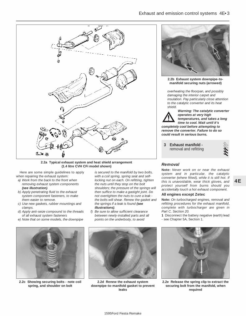
Here are some simple guidelines to applywhen repairing the exhaust system:a) Work from the back to the front when
removing exhaust system components(see illustration).
b) Apply penetrating fluid to the exhaustsystem component fasteners, to makethem easier to remove.
c) Use new gaskets, rubber mountings andclamps.
d) Apply anti-seize compound to the threadsof all exhaust system fasteners
e) Note that on some models, the downpipe
is secured to the manifold by two bolts,with a coil spring, spring seat and self-locking nut on each. On refitting, tightenthe nuts until they stop on the boltshoulders; the pressure of the springs willthen suffice to make a gastight joint. Donot overtighten the nuts to cure a leak -the bolts will shear. Renew the gasket andthe springs if a leak is found (seeillustrations).
f) Be sure to allow sufficient clearancebetween newly-installed parts and allpoints on the underbody, to avoid
overheating the floorpan, and possiblydamaging the interior carpet andinsulation. Pay particularly close attentionto the catalytic converter and its heatshield.
Warning: The catalytic converteroperates at very hightemperatures, and takes a longtime to cool. Wait until it’s
completely cool before attempting toremove the converter. Failure to do socould result in serious burns.
3 Exhaust manifold -removal and refitting 3
RemovalNote: Never work on or near the exhaustsystem and in particular, the catalyticconverter (where fitted), while it is still hot. Ifthis is unavoidable, wear thick gloves, andprotect yourself from burns should youaccidentally touch a hot exhaust component.
All engines except ZetecNote: On turbocharged engines, removal andrefitting procedures for the exhaust manifold,complete with turbocharger are given in Part C, Section 20.1 Disconnect the battery negative (earth) lead- see Chapter 5A, Section 1.
Exhaust and emission control systems 4E•3
2.2b Exhaust system downpipe-to-manifold securing nuts (arrowed)
2.2a Typical exhaust system and heat shield arrangement (1.4 litre CVH CFi model shown)
2.2e Release the spring clip to extract thesecuring bolt from the manifold, when
required
2.2d Renew the exhaust systemdownpipe-to-manifold gasket to prevent
leaks
2.2c Showing securing bolts - note coilspring, and shoulder on bolt
4E
1595Ford Fiesta Remake

2 The exhaust manifold is secured thecylinder head by studs and nuts, and issimilarly attached to the exhaust downpipe. Ashroud/heat shield is bolted to the manifold,to direct exhaust-heated air into the air inletsystem when the engine is cold. Access to theexhaust manifold retaining nuts is gained byfirst removing this shroud (see illustration).3 On vehicles equipped with a pulse-airsystem, remove the pulse-air piping asdescribed in Section 7.4 Support the exhaust downpipe on a jack orsuitable blocks, and undo the downpipe-to-manifold retaining nuts. Separate the pipefrom the manifold, and remove the gasket. Oncatalytic converter-equipped vehicles with anoxygen sensor fitted to the exhaustdownpipe, take care not to stretch the sensorwiring; if necessary, disconnect the sensor’smulti-plug.5 Undo the retaining nuts, and withdraw themanifold from the cylinder head studs.Remove the manifold gasket.
Zetec enginesNote: In addition to the new gasket and anyother parts, tools or facilities needed to carryout this operation, a new plastic guide sleevewill be required on reassembly.6 Disconnect the battery negative (earth) lead- see Chapter 5A, Section 1.7 Remove the air inlet components asdescribed in Part D of this Chapter.8 Drain the cooling system (see Chapter 1).9 Disconnect the coolant hose and thecoolant pipe/hose from the thermostathousing; secure them clear of the workingarea.10 Unbolt the exhaust manifold heat shield,and withdraw both parts of the shield (seeillustration).11 While the manifold can be removed withthe pulse-air system components attached -unbolt the filter housing and disconnect itsvacuum hose if this is to be done - it is easierto remove the pulse-air assembly first, asdescribed in Section 7.
12 Unplug the oxygen sensor electricalconnector, to avoid straining its wiring.Unscrew the nuts to disconnect the exhaustsystem front downpipe from the manifold.13 Remove the nuts and detach the manifoldand gasket (see illustration). When removingthe manifold with the engine in the vehicle,additional clearance can be obtained byunscrewing the studs from the cylinder head;a female Torx-type socket will be required.14 Always fit a new gasket on reassembly, tocarefully-cleaned components. Do notattempt to re-use the original gasket.
Inspection15 Use a scraper to remove all traces of oldgasket material and carbon deposits from themanifold and cylinder head mating surfaces.Provided both mating surfaces are clean andflat, a new gasket will be sufficient to ensurethat the joint is gastight. Do not use any kindof exhaust sealant upstream of the catalyticconverter, where fitted.16 Note that on some models, the downpipe issecured to the manifold by two bolts, with a coilspring, spring seat and self-locking nut on each.On refitting, tighten the nuts until they stop onthe bolt shoulders; the pressure of the springswill then suffice to make a gastight joint.17 Do not overtighten the nuts to cure a leak -the bolts will shear; renew the gasket and thesprings if a leak is found. The bolts themselvesare secured by spring clips to the manifold,and can be renewed easily if damaged.
Refitting18 Refitting is the reverse of the removalprocedure, noting the following points:a) Position a new gasket over the cylinder
head studs, and on Zetec engines, fit anew plastic guide sleeve to the studnearest to the thermostat housing, so thatthe manifold will be correctly located (seeillustration). Do not refit the manifoldwithout this sleeve.
b) Refit the manifold, and finger-tighten themounting nuts.
c) Working from the centre out, and in threeor four equal steps, tighten the nuts to thetorque wrench settings given in theSpecifications.
4E•4 Exhaust and emission control systems
3.18 Fit a new plastic guide sleeve to thestud (arrowed) when refitting the manifold
(Zetec engine models)
3.13 Exhaust manifold retaining nuts(Zetec engine models)
3.10 Exhaust manifold heat shield bolts(arrowed) (Zetec engine models)
3.2 Exploded view of the exhaust manifold arrangement (1.6 litre CVH EFi engine models)
1 Retaining stud2 Gasket3 Heatshield
4 Exhaust manifold5 Manifold retaining nut6 Centring hole
7 Heatshield retaining bolt8 Cylinder head
1595Ford Fiesta Remake

d) Refit the remaining parts in the reverseorder of removal. Tighten all fasteners tothe specified torque wrench settingswhere given.
e) Where drained, refill the cooling system(see Chapter 1).
f) Run the engine, and check for exhaustleaks. Check the coolant level when fullywarmed-up to normal operatingtemperature.
4 Catalytic converter - generalinformation and precautions
The catalytic converter is a reliable andsimple device, which needs no maintenancein itself, but there are some facts of which anowner should be aware if the converter is tofunction properly for its full service life.a) DO NOT use leaded petrol in a vehicle
equipped with a catalytic converter - thelead will coat the precious metals,reducing their converting efficiency, andwill eventually destroy the converter.
b) Always keep the ignition and fuel systemswell-maintained in accordance with themanufacturer’s schedule (see Chapter 1).
c) If the engine develops a misfire, do notdrive the vehicle at all (or at least as littleas possible) until the fault is cured.
d) DO NOT push - or tow-start the vehicle -this will soak the catalytic converter inunburned fuel, causing it to overheatwhen the engine does start.
e) DO NOT switch off the ignition at highengine speeds, ie do not “blip” thethrottle immediately before switching off.
f) DO NOT use fuel or engine oil additives -these may contain substances harmful tothe catalytic converter.
g) DO NOT continue to use the vehicle if theengine burns oil to the extent of leaving avisible trail of blue smoke.
h) Remember that the catalytic converteroperates at very high temperatures. DONOT, therefore, park the vehicle in dryundergrowth, over long grass or piles ofdead leaves, after a long run.
I) Remember that the catalytic converter isFRAGILE. Do not strike it with toolsduring servicing work.
j) In some cases, a sulphurous smell (likethat of rotten eggs) may be noticed fromthe exhaust. This is common to manycatalytic converter-equipped vehicles.Once the vehicle has covered a fewthousand miles, the problem shoulddisappear. Low quality fuel with a highsulphur content will exacerbate this effect.
k) The catalytic converter used on a well-maintained and well-driven vehicle shouldlast for between 50 000 and 100 000 miles. If the converter is nolonger effective, it must be renewed.
5 Positive crankcaseventilation system - checkingand component renewal
2Checking1 Checking procedures for the systemcomponents are included in Chapter 1.
Component renewal - allengines except Zetec
Air cleaner components2 See Chapter 1.
Filter/oil separator and hoses3 All the components relating to the positivecrankcase ventilation system, with theexception of the HCS engine filter/adapterlocated on the underside of the air cleaner,may be removed by simple disconnection andwithdrawal (having noted all connections forsubsequent refitting).4 The refitting of all components is a reversalof the removal procedure, ensuring that theconnections are correctly made.
Component renewal - Zetecengines
Air cleaner components5 See Chapter 1.
Positive Crankcase Ventilation (PCV)valve6 The valve is plugged into the oil separatoron Zetec engines (see illustration).
Depending on the tools available, access tothe valve may be possible once the pulse-airassembly has been removed (see Section 7).If this is not feasible, proceed as outlined inparagraph 7 below.
Oil separator7 Remove the exhaust manifold (see Sec-tion 3). The positive crankcase ventilationvalve can now be unplugged and flushed, orrenewed, as required, as described in Chap-ter 1.8 Unbolt the oil separator from the cylinderblock/crankcase, and withdraw it; remove anddiscard the gasket.9 Flush out or renew the oil separator, asrequired (see Chapter 1).10 Refitting is the reverse of the removalprocedure, but use a new gasket between theoil separator and cylinder block. Refill thecooling system (see Chapter 1). Run theengine, check for exhaust leaks, and checkthe coolant level when it is fully warmed-up.
6 Evaporative emissionscontrol system - checkingand component renewal
2Checking1 Poor idle, stalling and poor driveability canbe caused by an inoperative canister-purgesolenoid valve, a damaged canister, split orcracked hoses, or hoses connected to thewrong fittings. Check the fuel filler cap for adamaged or deformed gasket.
Exhaust and emission control systems 4E•5
5.6 Crankcase emission control system (Zetec engine models)
1 Oil separator2 Gasket3 Positive crankcase ventilation (PCV) valve
4 Cylinder block/crankcase opening5 Crankcase breather pipe and flexible
hoses
4E
1595Ford Fiesta Remake

2 Fuel loss or fuel odour can be caused byliquid fuel leaking from fuel lines, a cracked ordamaged canister, an inoperative canister-purge solenoid valve, or disconnected,misrouted, kinked or damaged vapour orcontrol hoses.3 Inspect each hose attached to the canisterfor kinks, leaks and cracks along its entirelength. Repair or renew as necessary.4 Inspect the canister. If it is cracked ordamaged, renew it. Look for fuel leaking fromthe bottom of the canister. If fuel is leaking,renew the canister, and check the hoses andhose routing.5 If the canister-purge solenoid valve isthought to be faulty, unplug its electricalconnector and disconnect its vacuum hoses.Connect a battery directly across the valveterminals. Check that air can flow through thevalve passages when the solenoid is thusenergised, and that nothing can pass whenthe solenoid is not energised.6 Further testing should be left to a dealerservice department.
Component renewal
Charcoal canister-purge solenoidvalve7 The solenoid is located at or near to thebulkhead, behind the engine on the right-handside (see illustrations). Locate the solenoid,then remove any components as necessary toimprove access.
8 Disconnect the battery negative (earth) lead(refer to Chapter 5A, Section 1), then unplugthe valve’s electrical connector. Unclip thevalve from its location, then disconnect itsvacuum hoses and withdraw it.9 Refitting is the reverse of the removalprocedure.
Charcoal canister10 Disconnect the battery negative (earth)lead (refer to Chapter 5A, Section 1).11 The canister is located in the front right-hand corner of the engine compartment.12 Disconnect the vapour pipe from the unit,and plug it to prevent the ingress of dirt (seeillustrations)13 Undo the retaining screw and withdrawthe unit upwards, releasing it from its bracket(see illustration).14 Refit in the reverse order of removal.Unplug the vapour pipe before reconnectingit, and ensure that it is clean and securelyconnected.
7 Pulse-air system - checkingand component renewal 2
Checking1 Poor idle, stalling, backfiring and poordriveability can be caused by a fault in thepulse-air system.
2 Inspect the vacuum pipe/hose for kinks,leaks and cracks along its entire length.Repair or renew as necessary.3 Inspect the filter housing and piping. Ifeither is cracked or damaged, renew it.4 If the pulse-air solenoid valve is thought tobe faulty, unplug its electrical connector anddisconnect its vacuum hoses. Connect abattery directly across the valve terminals,and check that air can flow through the valvepassages when the solenoid is thusenergised, and that nothing can pass whenthe solenoid is not energised.5 Further testing should be left to a dealerservice department.
Component renewal
Pulse-air valve, filter and housing(HCS engines)6 Disconnect the battery negative (earth) lead(refer to Chapter 5A, Section 1).7 Disconnect the vacuum hose from the rearof the pulse-air valve assembly (seeillustration).8 Undo the retaining screws, and withdrawthe air-valve, filter and housing assembly fromthe mounting bracket.9 To dismantle the filter housing, undo thefour screws and separate the top from thebase of the housing; extract the foam filter,and clean it in a suitable solvent. If any of thehousing’s components are worn or damaged,the assembly must be renewed.
4E•6 Exhaust and emission control systems
7.7 Location of pulse-air valve (arrowed)(1.3 litre HCS CFi engine models)
6.13 Undo the retaining screw andwithdraw the canister upwards, releasing
the tag (arrowed) from its bracket
6.12b Canister location and fuel vapourpipe (arrowed) (Zetec engine models)
6.12a Fuel vapour pipe (A) and canisterretaining screw (B) (1.4 litre CVH
CFi engine models)
6.7b Canister purge solenoid valve(arrowed) (Zetec engine models)
6.7a Canister purge solenoid valve (A) andmulti-plug (B) (1.4 litre CVH CFi engine
models)
1595Ford Fiesta Remake

10 Refitting is the reverse of the removalprocedure.
Pulse-air valve, filter and housing(Zetec engines)11 Disconnect the battery negative (earth)lead (refer to Chapter 5A, Section 1).12 Chock the rear wheels then jack up thefront of the car and support it on axle stands(see “Jacking and vehicle support”).13 Disconnect the vacuum hose from the base of the filter housing (see illustration).14 Remove the air cleaner air inlet componentsfor access (refer to Part D of this Chapter).15 Remove the screws securing the filterhousing to the piping, unscrew the mountingbolt, then withdraw the housing.16 To dismantle the filter housing, undo thefour screws and separate the top from thebase of the housing. Extract the foam filter,and clean it in a suitable solvent. If any of thehousing’s components are worn or damaged,the assembly must be renewed.17 Refitting is the reverse of the removalprocedure.
Pulse-air solenoid valve18 Disconnect the battery negative (earth)lead (refer to Chapter 5A, Section 1).19 Releasing its wire clip, unplug theelectrical connector, then release the valvefrom its mounting bracket. Withdraw thevalve, then label and disconnect the twovacuum hoses (see illustration).20 Refitting is the reverse of the removalprocedure; ensure that the hoses are correctlyreconnected.
Pulse-air piping (HCS engines)21 Disconnect the battery negative (earth)lead (refer to Chapter 5A, Section 1).
22 Remove the air cleaner if necessary forimproved access (refer to Part B of thisChapter).23 Disconnect the vacuum hose from thepulse-air valve.24 Unbolt and detach the air tube from itsfixing to the exhaust manifold, cylinder headand transmission, according to engine type.25 Loosen off the four nuts securing the airdelivery tubes to the cylinder head exhaustports, then carefully withdraw the deliverytubes as a unit (see illustration). Do not applyundue force to the tubes as they aredetached.26 Carefully clean the piping, particularly itsthreads and those of the manifold. Remove alltraces of corrosion, which might prevent thepipes seating properly, causing air leaks whenthe engine is restarted.27 On refitting, insert the piping carefully intothe cylinder head ports, taking care not tobend or distort it. Apply anti-seize compoundto the threads, and tighten the retaining sleeve nuts while holding each pipe firmly inits port.28 The remainder of the refitting procedure isthe reverse of removal.
Pulse-air piping (Zetec engines)29 Disconnect the battery negative (earth)lead (refer to Chapter 5A, Section 1).30 Remove the air cleaner air inletcomponents for access (refer to Part D of thisChapter).31 Unbolt the exhaust manifold heat shield;unclip the coolant hose to allow the upperpart to be withdrawn.32 Chock the rear wheels then jack up thefront of the car and support it on axle stands(see “Jacking and vehicle support”).
33 Disconnect the vacuum hose at the baseof the pulse-air filter housing.34 Unscrew the two bolts securing the pipeassembly to the support bracket and the foursleeve nuts securing the pipes into theexhaust manifold (see illustration). Removethe pipes and filter housing as an assembly,taking care not to distort them.35 Carefully clean the piping, particularly itsthreads and those of the manifold. Remove alltraces of corrosion, which might prevent thepipes seating properly, causing air leaks whenthe engine is restarted.36 On refitting, insert the piping carefully intothe cylinder head ports, taking care not to bendor distort it. Apply anti-seize compound to thethreads, and tighten the retaining sleeve nutswhile holding each pipe firmly in its port; if asuitable spanner is available, tighten the sleeve nuts to the specified torque wrenchsetting.37 The remainder of the refitting procedure isthe reverse of removal.
Exhaust and emission control systems 4E•7
7.25 Pulse-air piping sleeve nuts (3 of 4arrowed) (1.3 litre HCS CFi engine models)
7.19 Pulse-air solenoid valve location(arrowed) under ignition module
7.13 Disconnecting the vacuum hose fromthe base of the filter housing - note thehousing retaining bolts (arrowed) (Zetec
engine models)
7.34 Pulse-air piping sleeve nuts (arrowed)(Zetec engine models)
4E
1595Ford Fiesta Remake

4E•8 Exhaust and emission control systems
1595Ford Fiesta Remake
Notes

5A
1595Ford Fiesta Remake
GeneralSystem type . . . . . . . . . . . . . . . . . . . . . . . . . . . . . . . . . . . . . . . . . . . . . . 12 volt, negative earth
BatteryRating - Cold cranking/Reserve capacity . . . . . . . . . . . . . . . . . . . . . . . . 270 A/50 RC, 360 A/60 RC, 500 A/70 RC, 590 A/90 RC or
650 A/130 RCCharge condition:Poor . . . . . . . . . . . . . . . . . . . . . . . . . . . . . . . . . . . . . . . . . . . . . . . . . . . . 12.5 voltsNormal . . . . . . . . . . . . . . . . . . . . . . . . . . . . . . . . . . . . . . . . . . . . . . . . . . 12.6 voltsGood . . . . . . . . . . . . . . . . . . . . . . . . . . . . . . . . . . . . . . . . . . . . . . . . . . . . 12.7 volts
AlternatorMake/type:Bosch . . . . . . . . . . . . . . . . . . . . . . . . . . . . . . . . . . . . . . . . . . . . . . . . . . . K1-55A, K1-70A, KC-70A or KC-90AMagneti-Marelli . . . . . . . . . . . . . . . . . . . . . . . . . . . . . . . . . . . . . . . . . . . . A127/55 or 127/70Mitsubishi . . . . . . . . . . . . . . . . . . . . . . . . . . . . . . . . . . . . . . . . . . . . . . . . A5T or A002TOutput (nominal at 13.5 volts with engine speed of 6000 rpm) . . . . . . . 55, 70 or 90 ampsRegulating voltage at 4000 rpm engine speed and 3 to 7 amp load . . . 14.0 to 14.6 voltsMinimum brush length . . . . . . . . . . . . . . . . . . . . . . . . . . . . . . . . . . . . . . 5.0 mm
Starter motorMake/type:Bosch . . . . . . . . . . . . . . . . . . . . . . . . . . . . . . . . . . . . . . . . . . . . . . . . . . . DM, DW or EVMagneti-Marelli . . . . . . . . . . . . . . . . . . . . . . . . . . . . . . . . . . . . . . . . . . . . M79 or M80RNippondenso . . . . . . . . . . . . . . . . . . . . . . . . . . . . . . . . . . . . . . . . . . . . . No type numbers givenMinimum brush length:Bosch and Magneti-Marelli . . . . . . . . . . . . . . . . . . . . . . . . . . . . . . . . . . . 8.0 mmNippondenso . . . . . . . . . . . . . . . . . . . . . . . . . . . . . . . . . . . . . . . . . . . . . 9.0 mm
Torque wrench settings Nm lbf ftAlternator mounting bolts . . . . . . . . . . . . . . . . . . . . . . . . . . . . . . . . . . . . 25 18Alternator adjustment bolt . . . . . . . . . . . . . . . . . . . . . . . . . . . . . . . . . . . 12 9Alternator adjustment centre lockbolt . . . . . . . . . . . . . . . . . . . . . . . . . . 22 16Adjuster link-to-mounting bracket bolt . . . . . . . . . . . . . . . . . . . . . . . . . . 12 9Alternator pulley nut:With key . . . . . . . . . . . . . . . . . . . . . . . . . . . . . . . . . . . . . . . . . . . . . . . . . 50 37Without key . . . . . . . . . . . . . . . . . . . . . . . . . . . . . . . . . . . . . . . . . . . . . . . 60 44Starter motor mounting bolts . . . . . . . . . . . . . . . . . . . . . . . . . . . . . . . . . 35 26Starter motor support bracket bolt . . . . . . . . . . . . . . . . . . . . . . . . . . . . . 25 18
Chapter 5 Part A:Starting and charging systems
Alternator - removal and refitting . . . . . . . . . . . . . . . . . . . . . . . . . . . 6Alternator brushes and voltage regulator - renewal . . . . . . . . . . . . . 7Auxiliary drivebelt check and renewal . . . . . . . . . . . . . . .See Chapter 1Battery - removal and refitting . . . . . . . . . . . . . . . . . . . . . . . . . . . . . 4Battery - testing and charging . . . . . . . . . . . . . . . . . . . . . . . . . . . . . . 3Battery, bulbs and fuses . . . . . . . . . . . . . . . . . . .See “Weekly Checks”
Charging system - testing . . . . . . . . . . . . . . . . . . . . . . . . . . . . . . . . . 5Electrical fault finding - general information . . . . . . . . . . . . . . . . . . . 2General information, precautions and battery disconnection . . . . . . 1Starter motor - removal and refitting . . . . . . . . . . . . . . . . . . . . . . . . . 9Starter motor - testing and overhaul . . . . . . . . . . . . . . . . . . . . . . . . . 10Starting system - testing . . . . . . . . . . . . . . . . . . . . . . . . . . . . . . . . . . 8
5A•1
Specifications
Contents
Easy, suitable fornovice with littleexperience
Fairly easy, suitablefor beginner withsome experience
Fairly difficult,suitable for competentDIY mechanic
Difficult, suitable forexperienced DIYmechanic
Very difficult,suitable for expert DIYor professional
Degrees of difficulty
54321

1 General information,precautions and batterydisconnection
General informationThe engine electrical system consists
mainly of the charging and starting systems.Because of their engine-related functions,these components are covered separatelyfrom the body electrical devices such as thelights, instruments, etc (which are covered inChapter 12). Information on the ignitionsystem is covered in Part B of this Chapter.
The electrical system is of the 12-voltnegative earth type.
The battery is of the low maintenance or“maintenance-free” (sealed for life) type and ischarged by the alternator, which is belt-drivenfrom the crankshaft pulley.
The starter motor is of the pre-engagedtype incorporating an integral solenoid. Onstarting, the solenoid moves the drive pinioninto engagement with the flywheel ring gearbefore the starter motor is energised. Oncethe engine has started, a one-way clutchprevents the motor armature being driven bythe engine until the pinion disengages fromthe flywheel.
PrecautionsFurther details of the various systems are
given in the relevant Sections of this Chapter.While some repair procedures are given, theusual course of action is to renew thecomponent concerned. The owner whoseinterest extends beyond mere componentrenewal should obtain a copy of the“Automobile Electrical & Electronic SystemsManual”, available from the publishers of thismanual.
It is necessary to take extra care whenworking on the electrical system to avoiddamage to semi-conductor devices (diodesand transistors), and to avoid the risk ofpersonal injury. In addition to the precautionsgiven in “Safety first!” at the beginning of thismanual, observe the following when workingon the system:
Always remove rings, watches, etc beforeworking on the electrical system. Even withthe battery disconnected, capacitivedischarge could occur if a component’s liveterminal is earthed through a metal object.This could cause a shock or nasty burn.
Do not reverse the battery connections.Components such as the alternator, electroniccontrol units, or any other components havingsemi-conductor circuitry could be irreparablydamaged.
If the engine is being started using jumpleads and a slave battery, connect thebatteries positive-to-positive and negative-to-negative (see “Jump starting”). This alsoapplies when connecting a battery charger.
Never disconnect the battery terminals, thealternator, any electrical wiring or any test
instruments when the engine is running.Do not allow the engine to turn the
alternator when the alternator is notconnected.
Never “test” for alternator output by“flashing” the output lead to earth.
Never use an ohmmeter of the typeincorporating a hand-cranked generator forcircuit or continuity testing.Always ensure that the battery negative leadis disconnected when working on theelectrical system.
Before using electric-arc weldingequipment on the car, disconnect the battery,alternator and components such as the fuelinjection/ignition electronic control unit toprotect them from the risk of damage.
Battery disconnectionSeveral systems fitted to the vehicle require
battery power to be available at all times, eitherto ensure that their continued operation (such asthe clock) or to maintain control unit memories(such as that in the engine managementsystem’s ECU) which would be wiped if thebattery were to be disconnected. Whenever thebattery is to be disconnected therefore, first notethe following, to ensure that there are nounforeseen consequences of this action:a) First, on any vehicle with central locking, it
is a wise precaution to remove the keyfrom the ignition, and to keep it with you,so that it does not get locked in, if thecentral locking should engage accidentallywhen the battery is reconnected.
b) On cars equipped with an enginemanagement system, the system’s ECU willlose the information stored in its memory -referred to by Ford as the “KAM” (Keep-Alive Memory) - when the battery isdisconnected. This includes idling andoperating values, and any fault codesdetected - in the case of the fault codes, ifit is thought likely that the system hasdeveloped a fault for which thecorresponding code has been logged, thevehicle must be taken to a Ford dealer forthe codes to be read, using the specialdiagnostic equipment necessary for this.Whenever the battery is disconnected, theinformation relating to idle speed controland other operating values will have to bere-programmed into the unit’s memory.The ECU does this by itself, but until then,there may be surging, hesitation, erratic idleand a generally inferior level ofperformance. To allow the ECU to relearnthese values, start the engine and run it asclose to idle speed as possible until itreaches its normal operating temperature,then run it for approximately two minutes at1200 rpm. Next, drive the vehicle as far asnecessary - approximately 5 miles of varieddriving conditions is usually sufficient - tocomplete the relearning process.
c) If the battery is disconnected while thealarm system is armed or activated, thealarm will remain in the same state when
the battery is reconnected. The sameapplies to the engine immobiliser system(where fitted).
d) If a Ford “Keycode” audio unit is fitted,and the unit and/or the battery isdisconnected, the unit will not functionagain on reconnection until the correctsecurity code is entered. Details of thisprocedure, which varies according to theunit and model year, are given in the“Ford Audio Systems Operating Guide”supplied with the vehicle when new, withthe code itself being given in a “RadioPassport” and/or a “Keycode Label” atthe same time. Ensure you have thecorrect code before you disconnect thebattery. For obvious security reasons, theprocedure is not given in this manual. Ifyou do not have the code or details of thecorrect procedure, but can supply proofof ownership and a legitimate reason forwanting this information, the vehicle’sselling dealer may be able to help.
Devices known as “memory-savers” (or“code-savers”) can be used to avoid some ofthe above problems. Precise details varyaccording to the device used. Typically, it isplugged into the cigarette lighter, and isconnected by its own wires to a spare battery;the vehicle’s own battery is then disconnectedfrom the electrical system, leaving the“memory-saver” to pass sufficient current tomaintain audio unit security codes and ECUmemory values, and also to run permanently-live circuits such as the clock, all the whileisolating the battery in the event of a short-circuit occurring while work is carried out.
Warning: Some of these devicesallow a considerable amount ofcurrent to pass, which can meanthat many of the vehicle’s
systems are still operational when themain battery is disconnected. If a“memory-saver” is used, ensure that thecircuit concerned is actually “dead” beforecarrying out any work on it!
2 Electrical fault finding -general information
Refer to Chapter 12.
3 Battery -testing and charging 1
Standard and low maintenancebattery - testing1 If the vehicle covers a small annual mileage,it is worthwhile checking the specific gravityof the electrolyte every three months todetermine the state of charge of the battery.Use a hydrometer to make the check andcompare the results with the following table.
5A•2 Starting and charging systems
1595Ford Fiesta Remake

Ambient Ambient temperature temperature above below 25°C (77°F) 25°C (77°F)
Fully-charged 1.210 to 1.230 1.270 to 1.29070% charged 1.170 to 1.190 1.230 to 1.250Fully-discharged 1.050 to 1.070 1.110 to 1.130
Note that the specific gravity readingsassume an electrolyte temperature of 15°C (60°F); for every 10°C (18°F) below 15°C(60°F) subtract 0.007. For every 10°C (18°F)above 15°C (60°F) add 0.007.2 If the battery condition is suspect, firstcheck the specific gravity of electrolyte ineach cell. A variation of 0.040 or morebetween any cells indicates loss of electrolyteor deterioration of the internal plates.3 If the specific gravity variation is 0.040 ormore, the battery should be renewed. If thecell variation is satisfactory but the battery isdischarged, it should be charged asdescribed later in this Section.
Maintenance-free battery -testing4 In cases where a “sealed for life”maintenance-free battery is fitted, topping-upand testing of the electrolyte in each cell is notpossible. The condition of the battery cantherefore only be tested using a batterycondition indicator or a voltmeter.5 If testing the battery using a voltmeter,connect the voltmeter across the battery andcompare the result with those given in theSpecifications under “charge condition”. Thetest is only accurate if the battery has notbeen subjected to any kind of charge for theprevious six hours. If this is not the case,switch on the headlights for 30 seconds, thenwait four to five minutes before testing thebattery after switching off the headlights. Allother electrical circuits must be switched off,so check that the doors and tailgate are fullyshut when making the test.6 If the voltage reading is less than 12.2 volts,then the battery is discharged, whilst areading of 12.2 to 12.4 volts indicates apartially discharged condition.7 If the battery is to be charged, remove itfrom the vehicle (Section 4) and charge it asdescribed later in this Section.
Standard and low maintenancebattery - chargingNote: The following is intended as a guideonly. Always refer to the manufacturer’srecommendations (often printed on a labelattached to the battery) before charging abattery.8 Charge the battery at a rate of 3.5 to 4 amps and continue to charge the battery atthis rate until no further rise in specific gravityis noted over a four hour period.9 Alternatively, a trickle charger charging atthe rate of 1.5 amps can safely be usedovernight.10 Specially rapid “boost” charges which areclaimed to restore the power of the battery in
1 to 2 hours are not recommended, as theycan cause serious damage to the batteryplates through overheating.11 While charging the battery, note that thetemperature of the electrolyte should neverexceed 37.8°C (100°F).
Maintenance-free battery -chargingNote: The following is intended as a guideonly. Always refer to the manufacturer’srecommendations (often printed on a labelattached to the battery) before charging abattery.12 This battery type takes considerablylonger to fully recharge than the standardtype, the time taken being dependent on theextent of discharge, but it can take anythingup to three days.13 A constant voltage type charger isrequired, to be set, when connected, to 13.9to 14.9 volts with a charger current below 25 amps. Using this method, the batteryshould be usable within three hours, giving avoltage reading of 12.5 volts, but this is for a partially discharged battery and, asmentioned, full charging can takeconsiderably longer.14 If the battery is to be charged from a fullydischarged state (condition reading less than12.2 volts), have it recharged by your Forddealer or local automotive electrician, as thecharge rate is higher and constant supervisionduring charging is necessary.
4 Battery - removal and refitting 1
Note: Refer to the precautions in Section 1before starting work.
Removal1 The battery is located forward on the left-hand side of the engine compartment, on aplatform welded to the vehicle structure.2 Undo the retaining nut, then detach theearth leads from the stud of the batterynegative (earth) terminal post. This is theterminal to disconnect before working on, ordisconnecting, any electrical component onthe vehicle.3 Pivot up the plastic cover from the positiveterminal, then unscrew the positive leadretaining nut on the terminal. Detach thepositive lead from the terminal.4 Release the clamp securing the battery toits platform and remove it. Lift the batteryfrom its location, keeping it in an uprightposition to avoid the possibility of corrosiveelectrolyte spilling onto the paintwork.5 Clean the battery terminal posts, clampsand the battery casing. If the bulkhead isrusted as a result of battery acid spilling ontoit, clean it thoroughly and re-paint withreference to Chapter 1.
6 If you are renewing the battery, make surethat you get one that’s identical, with thesame dimensions, amperage rating, coldcranking rating, etc. Dispose of the old batteryin a responsible fashion. Most local authoritieshave facilities for the collection and disposalof such items - batteries contain sulphuricacid and lead, and should not be simplythrown out with the household rubbish!
Refitting7 Refitting is a reversal of removal. Smear thebattery terminals with a petroleum-based jellyprior to reconnecting. Always connect thepositive terminal clamp first and the negativeterminal clamp last.
5 Charging system - testing 2Note: Refer to the precautions in Section 1before starting work.1 If the ignition warning light fails toilluminate when the ignition is switched on,first check the alternator wiring connectionsfor security. If satisfactory, check that thewarning light bulb has not blown, and thatthe bulbholder is secure in its location in theinstrument panel. If the light still fails toilluminate, check the continuity of thewarning light feed wire from the alternator tothe bulbholder. If all is satisfactory, thealternator is at fault and should be renewedor taken to an auto-electrician for testing andrepair.2 If the ignition warning light illuminates whenthe engine is running, stop the engine andcheck that the drivebelt is correctly tensioned(see Chapter 1) and that the alternatorconnections are secure. If all is so farsatisfactory, have the alternator checked byan auto-electrician for testing and repair.3 If the alternator output is suspect eventhough the warning light functions correctly,the regulated voltage may be checked asfollows.4 Connect a voltmeter across the batteryterminals and start the engine.5 Increase the engine speed until thevoltmeter reading remains steady; the reading should be approximately 13.5 to 14.6 volts.6 Switch on as many electrical accessories(eg, the headlights, heated rear window andheater blower) as possible, and check that thealternator maintains the regulated voltage ataround 13 to 14 volts.7 If the regulated voltage is not as stated, thefault may be due to worn brushes, weak brushsprings, a faulty voltage regulator, a faultydiode, a severed phase winding or worn ordamaged slip rings. The alternator should berenewed or taken to an auto-electrician fortesting and repair.
Starting and charging systems 5A•3
5A
1595Ford Fiesta Remake
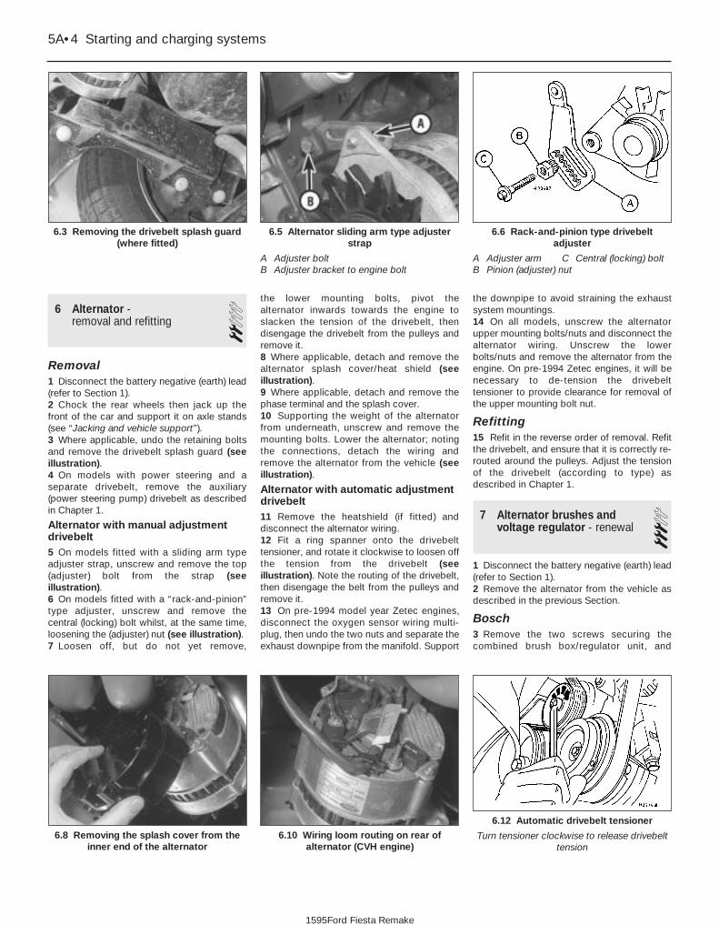
6 Alternator - removal and refitting 2
Removal1 Disconnect the battery negative (earth) lead(refer to Section 1).2 Chock the rear wheels then jack up thefront of the car and support it on axle stands(see “Jacking and vehicle support”).3 Where applicable, undo the retaining boltsand remove the drivebelt splash guard (seeillustration).4 On models with power steering and aseparate drivebelt, remove the auxiliary(power steering pump) drivebelt as describedin Chapter 1.
Alternator with manual adjustmentdrivebelt5 On models fitted with a sliding arm typeadjuster strap, unscrew and remove the top(adjuster) bolt from the strap (seeillustration).6 On models fitted with a “rack-and-pinion”type adjuster, unscrew and remove thecentral (locking) bolt whilst, at the same time,loosening the (adjuster) nut (see illustration).7 Loosen off, but do not yet remove,
the lower mounting bolts, pivot the alternator inwards towards the engine toslacken the tension of the drivebelt, thendisengage the drivebelt from the pulleys andremove it.8 Where applicable, detach and remove thealternator splash cover/heat shield (seeillustration).9 Where applicable, detach and remove thephase terminal and the splash cover.10 Supporting the weight of the alternatorfrom underneath, unscrew and remove themounting bolts. Lower the alternator; notingthe connections, detach the wiring andremove the alternator from the vehicle (seeillustration).
Alternator with automatic adjustmentdrivebelt11 Remove the heatshield (if fitted) anddisconnect the alternator wiring.12 Fit a ring spanner onto the drivebelttensioner, and rotate it clockwise to loosen offthe tension from the drivebelt (seeillustration). Note the routing of the drivebelt,then disengage the belt from the pulleys andremove it.13 On pre-1994 model year Zetec engines,disconnect the oxygen sensor wiring multi-plug, then undo the two nuts and separate theexhaust downpipe from the manifold. Support
the downpipe to avoid straining the exhaustsystem mountings.14 On all models, unscrew the alternatorupper mounting bolts/nuts and disconnect thealternator wiring. Unscrew the lowerbolts/nuts and remove the alternator from theengine. On pre-1994 Zetec engines, it will benecessary to de-tension the drivebelttensioner to provide clearance for removal ofthe upper mounting bolt nut.
Refitting15 Refit in the reverse order of removal. Refitthe drivebelt, and ensure that it is correctly re-routed around the pulleys. Adjust the tensionof the drivebelt (according to type) asdescribed in Chapter 1.
7 Alternator brushes andvoltage regulator - renewal 3
1 Disconnect the battery negative (earth) lead(refer to Section 1).2 Remove the alternator from the vehicle asdescribed in the previous Section.
Bosch3 Remove the two screws securing thecombined brush box/regulator unit, and
5A•4 Starting and charging systems
6.12 Automatic drivebelt tensioner
Turn tensioner clockwise to release drivebelttension
6.10 Wiring loom routing on rear ofalternator (CVH engine)
6.8 Removing the splash cover from theinner end of the alternator
6.6 Rack-and-pinion type drivebeltadjuster
A Adjuster arm C Central (locking) boltB Pinion (adjuster) nut
6.5 Alternator sliding arm type adjusterstrap
A Adjuster boltB Adjuster bracket to engine bolt
6.3 Removing the drivebelt splash guard(where fitted)
1595Ford Fiesta Remake

withdraw the assembly from the rear of thealternator (see illustrations).4 Check the brush lengths (see illustration).If either is less than, or close to, the minimumspecified length, renew them by unsolderingthe brush wiring connectors and withdrawingthe brushes and their springs.5 Clean the slip rings with a solvent-moistened cloth, then check for signs ofscoring, burning or severe pitting. If evident,the slip rings should be attended to by anautomobile electrician.6 Refit in the reverse order of removal.
Magneti-Marelli7 Remove the three screws securing theregulator/brush box unit on the rear face of thealternator, partially withdraw the assembly,detach the field connector, and remove theunit from the alternator (see illustrations).8 If the brushes are worn beyond theminimum allowable length specified, a newregulator and brush box unit must be fitted;the brushes are not available separately.9 Clean the slip rings with a solvent-moistenedcloth, then check for signs of scoring, burningor severe pitting. If evident, the slip rings shouldbe attended to by an automobile electrician.10 Refit in the reverse order of removal.
Mitsubishi11 Hold the pulley nut stationary using an 8 mm Allen key, unscrew the pulley nut andremove the washer (see illustration).
12 Withdraw the pulley, cooling fan, spacerand dust shield from the rotor shaft.13 Mark the relative fitted positions of the fronthousing, stator and rear housing (to ensure
correct re-alignment when reassembling).Unscrew the through-bolts and remove the fronthousing from the rotor shaft, followed by thedust seal and the thin spacer (see illustrations).
Starting and charging systems 5A•5
7.4 Measuring the brush lengths (Boschalternator)
7.3b . . . withdraw the brush box/regulatorunit (Bosch alternator)
7.11 Pulley nut removal on the Mitsubishialternator
7.13a Exploded view of the Mitsubishi A5T alternator
7.7b Disconnecting the field connector(Magneti-Marelli alternator)
7.7a Removing the regulator and brushboxassembly securing screws (Magneti-
Marelli alternator)
5A
1595Ford Fiesta Remake
7.3a Undo the retaining screw and . . .
A PulleyB FanC Thick spacerD Through-boltE Dust shieldF Drive end unitG BearingH Bearing retainerJ Dust capK Thin spacerL RotorM SealN BearingO Commutator endP Diode packR Brush boxS Stator

14 Remove the rotor from the rear housingand the stator. If difficulty is experienced, heatthe rear housing with a 200-watt solderingiron for three or four minutes.15 Unbolt the rectifier/brush box and statorassembly from the rear housing (seeillustration).16 Unsolder the stator and brush box fromthe rectifier, using the very minimum of heat.Use a pair of pliers as a heat sink to reducethe heat transference to the diodes(overheating may cause diode failure).17 Renew the brushes if they are worn downto, or beyond, the minimum specified length.Unsolder the brush wires at the pointsindicated (see illustration), then solder thenew brush leads so that the wear limit lineprojects 2 to 3 mm from the end of the holder(see illustration).18 Clean the slip rings with a solvent-moistened cloth, then check for signs ofscoring, burning or severe pitting. If evident,the slip rings should be attended to by anautomobile electrician.
19 Refit in the reverse order of removal.Insert a piece of wire through the access holein the rear housing to hold the brushes in theretracted position as the rotor is refitted (seeillustration). Do not forget to release thebrushes when assembled.
8 Starting system - testing 1Note: Refer to the precautions in Section 1before starting work.1 If the starter motor fails to operate when theignition key is turned to the appropriateposition, the following possible causes maybe to blame.a) The battery is faulty.b) The electrical connections between the
switch, solenoid, battery and startermotor are somewhere failing to pass thenecessary current from the batterythrough the starter to earth.
c) The solenoid is faulty.d) The starter motor is mechanically or
electrically defective.
2 To check the battery, switch on theheadlights. If they dim after a few seconds,this indicates that the battery is discharged -recharge (see Section 3) or renew the battery.If the headlights glow brightly, operate theignition switch and observe the lights. If theydim, then this indicates that current isreaching the starter motor, therefore the faultmust lie in the starter motor. If the lightscontinue to glow brightly (and no clickingsound can be heard from the starter motorsolenoid), this indicates that there is a fault inthe circuit or solenoid - see followingparagraphs. If the starter motor turns slowlywhen operated, but the battery is in goodcondition, then this indicates that either thestarter motor is faulty, or there is considerableresistance somewhere in the circuit.3 If a fault in the circuit is suspected,disconnect the battery leads (including theearth connection to the body), the starter/solenoid wiring and the engine/transmissionearth strap. Thoroughly clean theconnections, and reconnect the leads andwiring, then use a voltmeter or test lamp tocheck that full battery voltage is available atthe battery positive lead connection to thesolenoid, and that the earth is sound. Smearpetroleum jelly around the battery terminals toprevent corrosion - corroded connections areamongst the most frequent causes ofelectrical system faults.
5A•6 Starting and charging systems
7.19 Use a length of wire rod to holdbrushes in the retracted position when
reassembling the rotor to the housing onthe Mitsubishi alternator
7.17b Fitted position of new brush on aMitsubishi alternator
7.17a Unsoldering a brush wire on aMitsubishi alternator
7.15 Rectifier/brush box (1) and regulatorunit (3) retaining nuts on the Mitsubishialternator. Note that cap (2) covers the
regulator nut
A Pulley nutB Spring washerC PulleyD Through-boltE Retainer plate screwF Drive end housingG BearingH Bearing retaining plate
J SpacerK RotorL SpacerM Slip ring end bearingN PlugP CapQ Terminal insulatorR Slip ring end housing
S RectifierT Dust coverV RegulatorW Brush springX BrushY Regulator screwZ Stator
1595Ford Fiesta Remake
7.13b Exploded view of the AOO2T Mitsubishi alternator

4 If the battery and all connections are ingood condition, check the circuit bydisconnecting the wire from the solenoidblade terminal. Connect a voltmeter or testlamp between the wire end and a good earth(such as the battery negative terminal), andcheck that the wire is live when the ignitionswitch is turned to the “start” position. If it is,then the circuit is sound - if not the circuitwiring can be checked as described inChapter 12.5 The solenoid contacts can be checked byconnecting a voltmeter or test lamp betweenthe battery positive feed connection on thestarter side of the solenoid, and earth. Whenthe ignition switch is turned to the “start”position, there should be a reading or lightedbulb, as applicable. If there is no reading orlighted bulb, the solenoid is faulty and shouldbe renewed.6 If the circuit and solenoid are provedsound, the fault must lie in the starter motor.In this event, it may be possible to have thestarter motor overhauled by a specialist, butcheck on the cost of spares before
proceeding, as it may prove more economicalto obtain a new or exchange motor.
9 Starter motor -removal and refitting 1
Removal1 Disconnect the battery negative (earth) lead(refer to Section 1).2 Chock the rear wheels then jack up thefront of the car and support it on axle stands(see “Jacking and vehicle support”). Removethe front roadwheels.3 Undo the two retaining nuts, and removethe starter motor heat shield (where fitted).4 Prise free the cap, if fitted, then unscrew thenuts to disconnect the wiring from thestarter/solenoid terminals. Where applicable,disconnect the oxygen sensor wiring multi-plugfrom the locating bracket (see illustration).5 Unscrew and remove the starter motorretaining bolts at the transmission/clutch
housing and, where applicable, also unboltand detach the support bracket. Withdraw thestarter motor from its mounting, and remove itfrom the vehicle (see illustrations).
Refitting6 Refitting is a reversal of removal. Tightenthe retaining bolts to the specified torque.Ensure that the wiring is securely reconnectedto the starter motor (and solenoid) and isrouted clear of the exhaust downpipe.
10 Starter motor -testing and overhaul 4
If the starter motor is thought to be suspect, itshould be removed from the vehicle and takento an auto-electrician for testing. Most auto-electricians will be able to supply and fitbrushes at a reasonable cost. However, checkon the cost of repairs before proceeding as itmay prove more economical to obtain a newor exchange motor.
Starting and charging systems 5A•7
9.5b Starter motor rear support bracketand fasteners (arrowed)
9.5a Starter motor retaining bolts9.4 Disconnecting the wires from thestarter motor solenoid
5A
1595Ford Fiesta Remake

5A•8 Starting and charging systems
1595Ford Fiesta Remake
Notes

5B
1595Ford Fiesta Remake
GeneralSystem type:
1.0, 1.1 and 1.3 litre HCS engines with carburettor . . . . . . . . . . . . . . Distributorless ignition system (DIS) controlled by ignition module1.1 and 1.3 litre HCS engines with CFi fuel injection . . . . . . . . . . . . . Electronic distributorless ignition system (E-DIS) with ignition module
controlled by EEC IV engine management module1.4 litre CVH engines with carburettor:
Early models . . . . . . . . . . . . . . . . . . . . . . . . . . . . . . . . . . . . . . . . . . Distributor, with integral ignition amplifier moduleLater models . . . . . . . . . . . . . . . . . . . . . . . . . . . . . . . . . . . . . . . . . . Distributorless ignition system (DIS) controlled by ignition module
1.6 litre CVH engines with carburettor . . . . . . . . . . . . . . . . . . . . . . . . Distributor, with integral ignition amplifier module1.4 litre CVH engines with CFi fuel injection:
Pre-September 1990 models . . . . . . . . . . . . . . . . . . . . . . . . . . . . . Distributor, with ignition module, controlled by EEC IV enginemanagement module
September 1990 models onward . . . . . . . . . . . . . . . . . . . . . . . . . . Electronic distributorless ignition system (E-DIS) with ignition modulecontrolled by EEC IV engine management module
1.6 litre CVH engines with EFi fuel injection, and all PTE and Zetecengines . . . . . . . . . . . . . . . . . . . . . . . . . . . . . . . . . . . . . . . . . . . . . . . . Electronic distributorless ignition system (E-DIS) with ignition module
controlled by EEC IV engine management moduleFiring order:
HCS engines . . . . . . . . . . . . . . . . . . . . . . . . . . . . . . . . . . . . . . . . . . . . 1-2-4-3All other engines . . . . . . . . . . . . . . . . . . . . . . . . . . . . . . . . . . . . . . . . . 1-3-4-2
Location of No 1 cylinder . . . . . . . . . . . . . . . . . . . . . . . . . . . . . . . . . . . . Crankshaft pulley end
Ignition coilAll engines with distributor ignition systems:
Output . . . . . . . . . . . . . . . . . . . . . . . . . . . . . . . . . . . . . . . . . . . . . . . . . 30.0 kilovolts (minimum)Primary resistance . . . . . . . . . . . . . . . . . . . . . . . . . . . . . . . . . . . . . . . 0.72 to 0.88 ohmsSecondary resistance . . . . . . . . . . . . . . . . . . . . . . . . . . . . . . . . . . . . . 4500 to 7000 ohms
All engines with distributorless ignition systems:Output . . . . . . . . . . . . . . . . . . . . . . . . . . . . . . . . . . . . . . . . . . . . . . . . . 37.0 kilovolts (minimum)Primary resistance (measured at coil tower) . . . . . . . . . . . . . . . . . . . . 0.5 to 1.0 ohm
DistributorMake:
1.4 and 1.6 litre carburettor models . . . . . . . . . . . . . . . . . . . . . . . . . . Lucas1.4 litre CFi fuel injection models (pre-September 1990) . . . . . . . . . . Bosch
Direction of rotor arm rotation . . . . . . . . . . . . . . . . . . . . . . . . . . . . . . . . Anti-clockwise (viewed from cap)Automatic advance method:
1.4 and 1.6 litre carburettor models . . . . . . . . . . . . . . . . . . . . . . . . . . Mechanical and vacuum1.4 litre CFi fuel injection models (pre-September 1990) . . . . . . . . . . Totally controlled by EEC IV engine management module
Heat sink compound for ignition amplifier module (Lucas distributor) . . Ford part number 81 SF-12103-AA
Chapter 5 Part B:Ignition system
Crankshaft position sensor - removal and refitting . . . . . . . . . . . . . . 6Distributor cap and rotor arm - removal and refitting . . . . . . . . . . . . 7Distributor vacuum diaphragm unit - renewal . . . . . . . . . . . . . . . . . . 9Distributor - removal and refitting . . . . . . . . . . . . . . . . . . . . . . . . . . . 8General information and precautions . . . . . . . . . . . . . . . . . . . . . . . . 1Ignition coil - checking, removal and refitting . . . . . . . . . . . . . . . . . . 3
Ignition module - removal and refitting . . . . . . . . . . . . . . . . . . . . . . . 5Ignition system - testing . . . . . . . . . . . . . . . . . . . . . . . . . . . . . . . . . . 2Ignition timing - checking and adjustment . . . . . . . . . . . . . . . . . . . . 10Ignition amplifier module (distributor ignition systems) -
removal and refitting . . . . . . . . . . . . . . . . . . . . . . . . . . . . . . . . . . . 4Spark plug renewal . . . . . . . . . . . . . . . . . . . . . . . . . . . . .See Chapter 1
5B•1
Specifications
Contents
Easy, suitable fornovice with littleexperience
Fairly easy, suitablefor beginner withsome experience
Fairly difficult,suitable for competentDIY mechanic
Difficult, suitable forexperienced DIYmechanic
Very difficult,suitable for expert DIYor professional
Degrees of difficulty
54321

Ignition timing1.4 and 1.6 litre carburettor models with distributor:
For use with 4-star leaded petrol (97 RON) . . . . . . . . . . . . . . . . . . . . 12° BTDC at idle speed (vacuum pipe disconnected and plugged)For use with unleaded petrol (95 or 98 RON) . . . . . . . . . . . . . . . . . . . 8° BTDC at idle speed (vacuum pipe disconnected and plugged)
1.4 litre CFi fuel injection models with distributor (pre-Sept 1990) . . . . 10° BTDC at idle speed (set using STAR test equipment - refer to text)All other models . . . . . . . . . . . . . . . . . . . . . . . . . . . . . . . . . . . . . . . . . . . Totally controlled by ignition module or EEC IV engine management
module
Spark plugs . . . . . . . . . . . . . . . . . . . . . . . . . . . . . . . . . . . . . . . . . . . See Chapter 1 Specifications
Torque wrench settings Nm lbf ftCrankshaft position sensor (all engines except Zetec) . . . . . . . . . . . . . . 3 to 4 2 to 3Crankshaft position sensor to bracket (Zetec engines) . . . . . . . . . . . . . 7 to 9 5 to 7Crankshaft position sensor bracket to engine (Zetec engines) . . . . . . . 18 to 23 13 to 17DIS/E-DIS ignition coil to bracket . . . . . . . . . . . . . . . . . . . . . . . . . . . . . . 5 to 7 4 to 5DIS/E-DIS ignition coil bracket to engine (all engines except Zetec) . . . 9 to 12 7 to 9DIS/E-DIS ignition coil bracket to engine (Zetec engines) . . . . . . . . . . . 18 to 23 13 to 17
5B•2 Ignition system
1595Ford Fiesta Remake
1 General information andprecautions
General informationThe ignition system is responsible for
igniting the air/fuel mixture in each cylinder, atthe correct moment in relation to enginespeed and load, as the electrical sparkgenerated jumps the spark plug gap.
The ignition system is based on feeding lowtension (LT) voltage from the battery to theignition coil where it is converted to hightension (HT) voltage. The high tension voltageis powerful enough to jump the spark pluggap in the cylinders many times a secondunder high compression pressures, providingthat the system is in good condition.
A number of different ignition systems havebeen fitted to Fiesta models depending on theyear of manufacture, type of fuel system fittedand the emission level that the vehicle hasbeen designed to meet. Broadly speaking thesystems can be sub-divided into twocategories - distributor ignition systems anddistributorless ignition systems.
One version of the distributor ignitionsystem is fitted to all CVH engines withcarburettors. A second (more sophisticated)version is fitted to pre-September 1990 CVHengines with CFi fuel injection.
Distributorless ignition systems are fitted toall HCS, PTE and Zetec engines, and to allCVH engines with fuel injection except pre-September 1990 CFi versions.
Distributor ignition systems (CVHengines with carburettor)
The ignition system is divided into twocircuits; low tension (primary) and hightension (secondary). The low tension circuitconsists of the battery, ignition switch, coilprimary windings, ignition amplifier moduleand the signal generating system inside the
distributor. The signal generating systemcomprises the trigger coil, trigger wheel,stator, permanent magnet and trigger coil toignition amplifier module connector. The hightension circuit consists of the coil secondarywindings, the HT lead from the coil to thedistributor cap, the distributor cap, the rotorarm, the HT leads from the distributor cap tothe spark plugs and the spark plugsthemselves.
When the system is in operation, lowtension voltage is changed in the coil into hightension voltage by the action of the electronicamplifier module in conjunction with the signalgenerating system. Any change in themagnetic field force (flux), created by themovement of the trigger wheel relative to themagnet, induces a voltage in the trigger coil.This voltage is passed to the ignition amplifiermodule which switches off the ignition coilprimary circuit. This results in the collapse ofthe magnetic field in the coil which generates the high tension voltage. The hightension voltage is then fed, via the coil HTlead and the carbon brush in the centre of thedistributor cap, to the rotor arm. The voltagepasses across to the appropriate metalsegment in the cap and via the spark plug HTlead to the spark plug where it finally jumpsthe spark plug gap to earth.
The distributor is driven by an offset drivedog locating to a correspondingly offset slotin the end of the camshaft.
The ignition advance is a function of thedistributor and is controlled both mechanicallyand by a vacuum operated system. Themechanical governor mechanism consists oftwo weights which move out from thedistributor shaft as the engine speed rises dueto centrifugal force. As they move outwards,they rotate the trigger wheel relative to thedistributor shaft and so advance the spark.The weights are held in position by two lightsprings and it is the tension of the springswhich is largely responsible for correct sparkadvancement.
The vacuum control consists of adiaphragm, one side of which is connectedvia a small bore hose to the carburettor orthrottle housing, and the other side to thedistributor. Depression in the inlet manifoldand/or carburettor, which varies with enginespeed and throttle position, causes thediaphragm to move, so moving the stator andadvancing or retarding the spark. A finedegree of control is achieved by a spring inthe diaphragm assembly.
Additionally, one or more vacuum valvemay be incorporated in the vacuum linebetween the inlet manifold or carburettor andthe distributor. The function of these is tocontrol the vacuum felt at the distributor andto prevent fuel entering along the vacuum line(as applicable).
Distributor ignition systems (pre-September 1990 CVH engines withCFi fuel injection)
The ignition system is divided into twocircuits; low tension (primary) and hightension (secondary). The low tension circuitconsists of the battery, ignition switch, ignitionmodule, ballast resistor, coil primary windingsand “Hall effect” distributor. The high tensioncircuit consists of the coil secondarywindings, coil-to-distributor cap HT lead,distributor cap, rotor arm, spark plug HT leadsand spark plugs. The system is under theoverall control of the EEC IV enginemanagement module which also controls thefuel injection and emission control equipment.
When the system is in operation thedistributor supplies the EEC IV module with acrankshaft position reference signal to enablean initial ignition timing setting to beestablished. This signal is generated bymeans of a trigger vane attached to thedistributor shaft and which rotates in the gapbetween a permanent magnet and a sensor.The trigger vane has four cut-outs, one foreach cylinder. When one of the trigger vanecut-outs is in line with the sensor, magnetic

flux can pass between the magnet and thesensor. When a trigger vane segment is in linewith the sensor, the magnetic flux is divertedthrough the trigger vane, away from thesensor. The sensor detects the change inmagnetic flux and sends an impulse to theEEC IV module. Additional data is receivedfrom the engine coolant temperature sensor,manifold absolute pressure sensor, inlet airtemperature sensor, throttle position sensorand vehicle speed sensor. Using thisinformation the EEC IV module calculates theoptimum ignition advance setting andswitches off the low tension circuit via theignition module. This results in the collapse ofthe magnetic field in the coil which generatesthe high tension voltage. The high tensionvoltage is then fed, via the coil HT lead andthe carbon brush in the centre of thedistributor cap, to the rotor arm. The voltagepasses across to the appropriate metalsegment in the cap and via the spark plug HTlead to the spark plug where it finally jumpsthe spark plug gap to earth. It can be seenthat the ignition module functions basically asa high current switch by controlling the lowtension supply to the ignition coil primarywindings.
In the event of failure of a sensor, the EEC IV module will substitute a preset valuefor that input to allow the system to continueto function. In the event of failure of the EEC IV module, a “limited operation strategy”(LOS) function allows the vehicle to be driven,albeit at reduced power and efficiency. TheEEC IV module also has a “keep alivememory” (KAM) function which stores idle anddrive values and codes which can be used toindicate any system fault which may occur.
Distributorless ignition systemsThe main ignition system components
include the ignition switch, the battery, thecrankshaft speed/position sensor, the ignitionmodule, the coil, the primary (low tension/LT)and secondary (high tension/HT) wiringcircuits, and the spark plugs.
The system used on carburettor models istermed DIS (Distributorless Ignition System),and on fuel injection models E-DIS, (ElectronicDistributorless Ignition System). The primarydifference between the two is that the DISsystem is an independent ignition controlsystem while the E-DIS system operates inconjunction with the EEC IV enginemanagement module which also controls thefuel injection and emission control systems.
With both systems, the main functions ofthe distributor are replaced by a computerisedignition module and a coil unit. The coil unitcombines a double-ended pair of coils - eachtime a coil receives an ignition signal, twosparks are produced, at each end of thesecondary windings. One spark goes to acylinder on compression stroke and the othergoes to the corresponding cylinder on itsexhaust stroke. The first will give the correct
power stroke, but the second spark will haveno effect (a “wasted spark”), occurring as itdoes during exhaust conditions.
The ignition signal is generated by acrankshaft position sensor which scans aseries of 36 protrusions on the periphery ofthe engine flywheel. The inductive head of thecrankshaft position sensor runs just above theflywheel periphery and as the crankshaftrotates, the sensor transmits a pulse to theignition module every time a protrusionpasses it. There is one missing protrusion inthe flywheel periphery at a pointcorresponding to 90° BTDC. The ignitionmodule recognises the absence of a pulsefrom the crankshaft position sensor at thispoint to establish a reference mark forcrankshaft position. Similarly, the time intervalbetween absent pulses is used to determineengine speed.
On carburettor engines, the ignition modulereceives signals provided by informationsensors which monitor various enginefunctions (such as crankshaft position,coolant temperature, inlet air temperature,inlet manifold vacuum etc). This informationallows the ignition module to generate theoptimum ignition timing setting under alloperating conditions.
On fuel injection engines, the ignitionmodule operates in conjunction with the EEC IV engine management module, andtogether with the various additionalinformation sensors and emission controlcomponents, provides total control of the fueland ignition systems to form a completeengine management package.
The information contained in this Chapterconcentrates on the ignition-relatedcomponents of the engine managementsystem. Information covering the fuel, exhaustand emission control components can befound in the applicable Parts of Chapter 4.
PrecautionsWhen working on the ignition system, take
the following precautions:a) Do not keep the ignition switch on for
more than 10 seconds if the engine willnot start.
b) If a separate tachometer is ever requiredfor servicing work, consult a dealerservice department before buying atachometer for use with this vehicle -some tachometers may be incompatiblewith these types of ignition systems - andalways connect it in accordance with theequipment manufacturer’s instructions.
c) Never connect the ignition coil terminalsto earth. This could result in damage tothe coil and/or the ignition module.
d) Do not disconnect the battery when theengine is running.
e) Make sure that the ignition module isproperly earthed.
f) Refer to the warning at the beginning ofthe next Section concerning HT voltage.
2 Ignition system - testing 2Warning: Voltages produced byan electronic ignition system areconsiderably higher than thoseproduced by conventional
ignition systems. Extreme care must betaken when working on the system withthe ignition switched on. Persons withsurgically-implanted cardiac pacemakerdevices should keep well clear of theignition circuits, components and testequipment.
Note: Refer to the precautions given inSection 1 of Part A of this Chapter beforestarting work. Always switch off the ignitionbefore disconnecting or connecting anycomponent and when using a multi-meter tocheck resistances.
1 If the engine turns over but won’t start,disconnect the (HT) lead from any spark plug,and attach it to a calibrated tester (available atmost automotive accessory shops). Connectthe clip on the tester to a good earth - a boltor metal bracket on the engine. If you’reunable to obtain a calibrated ignition tester,have the check carried out by a Ford dealerservice department or similar. Any other formof testing (such as jumping a spark from theend of an HT lead to earth) is notrecommended, because of the risk ofpersonal injury, or of damage to the ignitionmodule.2 Crank the engine, and watch the end of thetester to see if bright blue, well-defined sparksoccur.3 If sparks occur, sufficient voltage isreaching the plug to fire it. Repeat the check at the remaining plugs, to ensure that all leads are sound and that the coil is serviceable. However, the plugs themselves may be fouled or faulty, soremove and check them as described inChapter 1.4 If no sparks or intermittent sparks occur,the spark plug lead(s) may be defective. Also,on distributor systems, there may beproblems with the rotor arm or distributor cap- check all these components as described inChapter 1.5 If there’s still no spark, check the coil’selectrical connector (where applicable), tomake sure it’s clean and tight. Check for fullbattery voltage to the coil at the connector’scentre terminal. Check the coil itself (seeSection 3). Make any necessary repairs, thenrepeat the check again.6 The remainder of the system checks shouldbe left to a dealer service department or other qualified repair facility, as there is achance that the ignition module may be damaged if tests are not performedproperly.
Ignition system 5B•3
5B
1595Ford Fiesta Remake

3 Ignition coil - checking,removal and refitting 2
Distributor ignition systems
Checking1 Accurate checking of the coil outputrequires the use of special test equipment andshould be left to a dealer or suitably equippedautomotive electrician. It is however possibleto check the primary and secondary windingresistance using an ohmmeter as follows.2 Disconnect the battery negative (earth) lead(refer to Part A, Section 1).3 Remove the vehicle jack from its storageposition by unscrewing its retainer. Theignition coil is mounted below.4 To check the primary resistance (with allleads disconnected if the coil is fitted),connect the ohmmeter across the coil positiveand negative terminals. The resistance shouldbe as given in the Specifications at thebeginning of this Chapter.5 To check the secondary resistance (with allleads disconnected if the coil is fitted),connect one lead from the ohmmeter to thecoil negative terminal, and the other lead tothe centre HT terminal. Again the resistanceshould be as given in the Specifications.6 If any of the measured values varysignificantly from the figures given in theSpecifications, the coil should be renewed.7 If a new coil is to be fitted, ensure that it isof the correct type. The appropriate Fordsupplied ignition coil is identified by a redlabel, and will be one of three different makes,all of which are fully interchangeable. Boschand Femsa coils are fitted with protectiveplastic covers, and Polmot coils are fitted withan internal fusible link. Note that contactbreaker ignition coils are not interchangeablewith the required breakerless type and couldcause ignition module failure if used.
Removal8 If not already done, remove the vehicle jack
from its storage position by unscrewing itsretainer. The ignition coil is mounted below.9 Disconnect the battery negative (earth) lead(refer to Part A, Section 1).10 Disconnect the HT lead and the lowtension (LT) connections from the ignition coil.Note that the LT connections on the ignitioncoil are of different sizes. As an aid to refittingthe positive (+) terminal is larger than thenegative (-) terminal (see illustration).11 Remove the two screws or bolts securingthe coil mounting bracket to the inner wingpanel, and withdraw the coil and mountingbracket assembly.
Refitting12 Refitting is a reversal of the removalprocedure, ensuring correct LT lead polarity.
Distributorless ignition systems
CheckingNote: The ignition coil is located on the rearfacing side of the cylinder block on HCSengines; on the left-hand end of the cylinderhead on CVH, PTE and Zetec engines.13 Having checked that full battery voltage isavailable at the centre terminal of the coil’selectrical connector (see Section 2),disconnect the battery negative (earth) lead(refer to Part A, Section 1).14 Unplug the coil’s electrical connector, ifnot already disconnected.15 Using an ohmmeter, measure theresistance of the coil’s primary windings,connecting the meter between the coil’sterminal pins as follows. Measure first fromone outer pin to the centre pin, then from theother outer pin to the centre. Compare thereadings with the coil primary resistance listedin the Specifications.16 Disconnect the spark plug (HT) leads -note their connections or label them carefully,as described in Chapter 1. Use the meter tocheck that there is continuity between eachpair of (HT) lead terminals; Nos 1 and 4terminals are connected by their secondarywinding, as are Nos 2 and 3. Now switch to
the highest resistance scale, and check thatthere is no continuity between either pair ofterminals and the other - ie, there should beinfinite resistance between terminals 1 and 2,or 4 and 3 - and between any terminal andearth.17 If either of the above tests yield resistancevalues outside the specified amount, orresults other than those described, renew thecoil. Any further testing should be left to adealer service department or other qualifiedrepair facility.
RemovalNote: The ignition coil is located on the rearfacing side of the cylinder block on HCSengines; on the left-hand end of the cylinderhead on CVH, PTE and Zetec engines.18 Disconnect the battery negative (earth)lead (refer to Part A, Section 1).19 Disconnect the coil main electricalconnector and (where fitted) the electricalconnector to the suppressor.20 The coil can be removed with the HTleads left attached, in which case disconnectthe leads from their respective spark plugsand from the location clips in the rocker coveror air inlet duct (as applicable). If preferred,the HT leads can be disconnected from thecoil. First check that both the ignition HTleads and their fitted positions are clearlymarked numerically to ensure correct refitting.Spot mark them accordingly if necessary,using quick-drying paint.21 If disconnecting the leads from the sparkplugs, pull them free by gripping on theconnector, not the lead. To detach the leadsfrom the ignition coil, compress the retainingarms of each lead connector at the coil, anddetach each lead in turn (see illustration).22 Unscrew the Torx-type retaining screws,and remove the coil from its mounting on theengine (see illustration).
Refitting23 Refitting is the reverse of the removalprocedure. Ensure that the spark plug (HT)leads are correctly reconnected, and tightenthe coil screws securely.
5B•4 Ignition system
3.22 Distributorless ignition system ignitioncoil and mounting bracket removal (HCS
engine shown)
3.21 Removing an HT lead from thedistributorless ignition system ignition coil.
Note the corresponding markings on theignition coil and HT lead (arrowed)
3.10 Ignition coil fitted to distributorignition systems
A Retaining boltsB LT connectionsC HT lead to distributor cap
1595Ford Fiesta Remake

4 Ignition amplifier module(distributor ignition systems)- removal and refitting
2Note: The ignition amplifier module is onlyfitted to carburettor engine models.
Removal1 Disconnect the battery negative (earth) lead(refer to Part A, Section 1).2 Remove the distributor, as described inSection 8.3 With the distributor on the workbench,remove both screws securing the module tothe distributor body, then slide the modulefrom its trigger coil connector and remove it.4 Check that the rubber grommet isserviceable. If it is not, it must be renewed butensure that the correct type is obtained.
Refitting5 Apply heat sink compound (seeSpecifications) to the module metal face,ensuring a good earth. This is an essentialpart of the procedure, protecting the moduleelectronic circuitry from excessive heat build-up and subsequent malfunction.6 Slide the module into its trigger coilconnector and secure with both screws.7 Refit the distributor in accordance withSection 8, then reconnect the battery.
5 Ignition module - removal and refitting 1
Note: Various designs of ignition module maybe fitted depending on ignition system type.Although the units may differ in appearancefrom the those shown in the accompanyingillustrations, the procedures described beloware applicable to all types.
Removal1 The ignition module is located on theengine compartment bulkhead.2 Disconnect the battery negative (earth) lead(refer to Part A, Section 1).3 Where applicable, detach the vacuum hosefrom the module (see illustration).4 According to type, either compress thelocktab securing the wiring multi-plug inposition, or where applicable, undo theretaining bolt, then withdraw the plug from themodule (see illustrations).5 Undo the retaining screws, and remove the module from the bulkhead (seeillustration).
Refitting6 Refitting is the reverse of the removalprocedure.
6 Crankshaft position sensor -removal and refitting 2
Removal1 Disconnect the battery negative (earth) lead(refer to Part A, Section 1).2 Chock the rear wheels then jack up thefront of the car and support it on axle stands(see “Jacking and vehicle support”).3 If working on the Zetec engine, remove thestarter motor as described in Part A of thisChapter.4 Compress the retaining clip and pull freethe wiring multi-plug connector from thesensor unit, but take care to pull on theconnector, not the lead (see illustration).5 Undo the Torx-type retaining screw, andwithdraw the sensor from its location in thecylinder block bellhousing flange.
Refitting6 Refitting is the reversal of removal.
7 Distributor cap and rotorarm - removal and refitting 1
Removal1 Disconnect the battery negative (earth) lead(refer to Part A, Section 1).2 Disconnect the coil HT lead from the centreof the distributor cap and the spark plug HTleads from the spark plugs, having identifiedthem for subsequent refitting. Pull on theconnectors, not the leads. Release the leadsfrom any cable clips or ties.3 On carburettor models, unclip thesuppressor shield (where fitted), remove thedistributor cap securing screws and detachthe cap.4 On CFi fuel injection models, disconnectthe distributor multi-plug for better access tothe rear cap securing clip. Release thedistributor cap securing clips by levering witha screwdriver, withdraw the cap assembly
Ignition system 5B•5
5.4b Undoing the ignition module multi-plug securing bolt
5.4a Disconnecting the ignition modulemulti-plug
5.3 Disconnecting the vacuum pipe fromthe ignition module
6.4 Crankshaft position sensor removal
A Retaining screw B Multi-plug
5.5 Ignition module location on bulkheadpanel. Note retaining screws (arrowed)
5B
1595Ford Fiesta Remake

and separate the suppressor shield from thecap (see illustrations).5 Withdraw the rotor arm from the distributorshaft.6 Before refitting, wipe clean the distributorcap and leads and carry out a carefulinspection as described in Chapter 1.
Refitting7 Refitting is a reversal of the removalprocedure, ensuring that the HT leads aresecurely connected and in the correct order.
8 Distributor -removal and refitting 2
Note: On pre-September 1990 CVH engineswith CFi fuel injection, unless the originaldistributor is to be refitted to the originalcylinder head, it will be necessary to take thevehicle to a Ford dealer for accurateadjustment of the ignition timing after refitting.
Removal1 Disconnect the battery negative (earth) lead(refer to Part A, Section 1).2 If the original distributor is to be refitted tothe original cylinder head, check that thepunch marks on the cylinder head anddistributor body are aligned before removingthe distributor (see illustration). If no marksare present, make your own using a punch or
small file to ensure correct alignment uponsubsequent refitting.3 Refer to Section 7 and remove thedistributor cap.4 On carburettor equipped CVH engines,disconnect the vacuum pipe from thedistributor vacuum diaphragm unit.5 Disconnect the wiring multi-plug from thedistributor.6 Remove the clamp bolts securing thedistributor in position and slide it out (seeillustration).7 Prior to refitting, check the condition of thedistributor oil seal and renew it if necessary.
Refitting
CVH engines with carburettor8 Position the distributor so that its offsetdrive is engaged with the slot in the end of thecamshaft, then loosely insert the two clampbolts.9 Where both original punch marks arepresent, on the cylinder head and distributorbody, rotate the distributor body until thepunch marks are aligned before fullytightening the clamp bolts.10 If one or both of the punch marks aremissing (due to component renewal), turn thebody of the distributor so that the clamp boltsare centrally located in their slots then fullytighten the bolts.11 Refit the rotor arm (if removed), distributorcap, suppressor shield (as applicable) and HT
leads, making reference to Section 7, thenreconnect the wiring multi-plug and vacuumpipe.12 Reconnect the battery negative lead.13 If one or both of the punch marks aremissing after component renewal, check theignition timing, as described in Section 10,and adjust as necessary. This will not berequired where the original punch marks havebeen re-aligned.
Pre-September 1990 CVH engineswith CFi fuel injection14 Position the distributor so that its offsetdrive is engaged with the slot in the end of thecamshaft, then loosely insert the two clampbolts.15 Where both original punch marks arepresent, on the cylinder head and distributorbody, rotate the distributor body until thepunch marks are aligned then fully tighten theclamp bolts.16 If one or both of the punch marks aremissing (due to component renewal), rotatethe distributor body until the centre linethrough the distributor multi-plug connector isat 40° to the vertical (see illustration), beforefully tightening the distributor clamp bolts.This will give an approximate (static) ignitiontiming setting to enable starting of the engine
5B•6 Ignition system
8.16 Distributor orientation when re-fittingif alignment punch marks are missing (Pre-September 1990 CVH engines with CFi fuel
injection)
A Direction of rotationB Centre line through distributor connector
(40º to vertical)8.6 Removing the distributor from the
cylinder head8.2 Distributor alignment punch marks
(arrowed)
7.4c Withdrawing the distributor cap andsuppressor shield assembly
7.4b Releasing one of the distributor capsecuring clips by carefully levering with a
screwdriver
7.4a Disconnecting the distributor multi-plug
1595Ford Fiesta Remake

after the remaining components have beenrefitted and the relevant connections made.17 Refit the rotor arm (if removed), distributorcap, suppressor shield (as applicable) and HTleads, making reference to Section 7, thenreconnect the wiring multi-plug.18 Reconnect the battery negative lead.19 If one or both of the punch marks aremissing after component renewal, the vehiclewill need to be taken to a Ford dealer foraccurate ignition timing checking and, ifnecessary, adjustment. This can only becarried out with the EEC IV enginemanagement module in “self-test” mode and connected to the Ford specialised testequipment (see Section 10, paragraph 19).
9 Distributor vacuumdiaphragm unit - renewal 2
Note: Check parts availability beforeproceeding with this operation.1 Remove the distributor, as described inSection 8.2 With the distributor on the workbench,remove the ignition amplifier module (seeSection 4) and the distributor cap and rotorarm (if not already done).3 Remove the three screws securing the
distributor body halves and separate theassembly (see illustration).4 Lift out the plastic spacer ring from theupper distributor body half (see illustration).5 Remove the trigger coil to ignition amplifiermodule connector and seal, having notedwhich way the connector fits for subsequentreassembly (see illustration).6 Lift out the trigger coil, before careful not todamage it or its connectors as it is withdrawn.7 Remove the stator securing circlip and theupper shim followed by the stator and thelower shim (see illustration).8 Undo the vacuum diaphragm unit securingscrew and detach the unit.9 This is the limit of dismantling that can beundertaken on these distributors. Should thedistributor be worn or unserviceable in anyother respect, renewal of the complete unitwill be necessary.10 Reassembling is a reversal of thedismantling procedure. During reassembly,ensure that the pin on the vacuum diaphragmunit arm engaged in the stator as the stator isrefitted, and fit the plastic spacer ring so thatits cut-out aligns with the trigger coil toignition amplifier module connector.Additionally, after the distributor body halves’securing screws have been tightened, ensurethat the distributor shaft turns easily. Refit theignition amplifier module in accordance withSection 4.
10 Ignition timing - checking and adjustment 2
Distributorless ignition systems1 The ignition timing is controlled entirely bythe ignition module (acting in conjunction withthe EEC IV engine management module onfuel injection engines), and can only bechecked and adjusted when the system isconnected to Ford diagnostic equipment.2 If the timing is thought to be incorrect, thiscan only be due to a fault in the ignitionmodule or engine management systemcomponents and the vehicle should be takento a Ford dealer for full testing and faultdiagnosis.
Distributor ignition systems (CVHengines with carburettor)Note: When an engine is timed in production,marks are punched into the cylinder head andthe distributor body flange to indicate thecorrect timing position of the distributor (seeillustration 8.2). Therefore, under normalcircumstances, ignition timing adjustment willonly be necessary if the initial setting has beendisturbed. An ignition timing setting for usewith unleaded petrol (95 RON) is given in theSpecifications3 Where the original punch marks are presenton the cylinder head and the distributor bodyflange, correct ignition timing can be set, asnecessary, by turning the body of thedistributor to align the marks before re-tightening the distributor clamp bolts.4 If, due to component renewal, one or bothof the original punch marks is missing, thefollowing procedure must be carried out.5 Turn the distributor body so that the clampbolts are located centrally in their slots thentighten the clamp bolts.6 Increase the contrast of the notch in thecrankshaft pulley and the appropriate mark onthe timing cover scale (refer to Specifications)by applying a dab of quick-drying white paint(see illustration).7 Connect a stroboscopic timing light in
Ignition system 5B•7
9.5 Trigger coil to ignition amplifiermodule connector (A) and seal
9.4 Remove the plastic spacer ring (A)9.3 Distributor body halves separated(ignition amplifier module also shown)
10.6 Crankshaft pulley timing notch(arrowed) and timing marks on the timing
cover scale
9.7 Stator and shim details
A Circlip C StatorB Upper shim D Lower shim
5B
1595Ford Fiesta Remake

accordance with the manufacturer’sinstructions.8 Start the engine, bring it up to normaloperating temperature and allow it to idle.9 Disconnect the vacuum pipe from thedistributor and fit blanking plugs.10 If the timing light is now directed at theengine timing marks, the pulley notch willappear to be stationary and opposite thespecified mark on the scale. If the marks arenot in alignment, release the distributor clampbolts slightly and turn the distributor body inwhichever direction is necessary to align thepulley notch to the appropriate scale mark.Tighten the clamp bolts fully when the settingis correct.11 Using a suitable punch, re-mark thecylinder head and/or the distributor flange toindicate the new distributor timing position forany future repair operations.12 The operation of the centrifugal advanceweights in the distributor can be checked byincreasing the engine speed with the timinglight pointing at the engine timing marks andobserving that the pulley notch advances fromits initial position.13 To check the vacuum advance, run theengine at a fast idle speed and reconnect the
vacuum pipe. The pulley notch should againadvance.14 Stop the engine, disconnect thetachometer and timing light and reconnect thevacuum pipe. Refit the timing aperture cover.15 If the timing notch did not appear to moveduring the centrifugal advance check, a faultin the distributor centrifugal advancemechanism is indicated. No increasedmovement of the notch during the vacuumadvance check indicate a punctureddiaphragm in the vacuum unit, or a leak in thevacuum line.16 On completion of the adjustments andchecks, switch the engine off, disconnect thetiming light and ensure that the distributorvacuum pipe is securely connected.
Distributor ignition systems (pre-September 1990 CVH engines withCFi fuel injection)Note: When an engine is timed in productionit is set, using a microwave timing system, toan accuracy of within half a degree. Unless itis essential, do not remove the distributor oralter the ignition timing. If no distributor timingposition punch marks are present on thecylinder head and distributor body flange,
make your own before disturbing the setting(see illustration 8.2).17 The method of obtaining correct ignitiontiming, with both original punch markspresent, is described in paragraph 3 above.18 If (due to component renewal) one or bothof the punch marks is missing, anapproximate ignition timing setting can beobtained to enable starting of the engine byfollowing the instruction given in Section 8,paragraph 16.19 Accurate ignition timing adjustment canonly be carried out using specialisedequipment - this is a task for your Ford dealeror other suitably equipped specialist. Thereason for this is that the EEC IV enginemanagement module has to “lock” its internalignition advance compensations and its idlespeed control whilst the timing is set. The“locking” of the EEC IV module is performedin “self-test” mode when connected to theFord STAR test (Self-Test Automatic Readout)equipment, which is also used to access faultcodes stored in the module memory andanalyse the performance of the systemcomponents. New punch marks should bemade after accurate timing has been carriedout, as necessary.
5B•8 Ignition system
1595Ford Fiesta Remake

9
1595Ford Fiesta Remake
Front brakesType . . . . . . . . . . . . . . . . . . . . . . . . . . . . . . . . . . . . . . . . . . . . . . . . . . . . Solid or ventilated disc, with single-piston sliding calipersDisc diameter . . . . . . . . . . . . . . . . . . . . . . . . . . . . . . . . . . . . . . . . . . . . . 240.0 mmDisc thickness:
Solid disc . . . . . . . . . . . . . . . . . . . . . . . . . . . . . . . . . . . . . . . . . . . . . . 10.0 mmVentilated disc . . . . . . . . . . . . . . . . . . . . . . . . . . . . . . . . . . . . . . . . . . 20.0 mm
Minimum disc thickness:Solid disc . . . . . . . . . . . . . . . . . . . . . . . . . . . . . . . . . . . . . . . . . . . . . . 8.0 mmVentilated disc . . . . . . . . . . . . . . . . . . . . . . . . . . . . . . . . . . . . . . . . . . 18.0 mm
Maximum disc run-out (disc fitted) . . . . . . . . . . . . . . . . . . . . . . . . . . . . . 0.1 mmMinimum brake pad thickness . . . . . . . . . . . . . . . . . . . . . . . . . . . . . . . . 1.5 mm
Rear brakesType . . . . . . . . . . . . . . . . . . . . . . . . . . . . . . . . . . . . . . . . . . . . . . . . . . . . Drum with leading and trailing shoes and automatic adjustersNominal drum diameter:
All except XR2i and ABS equipped models . . . . . . . . . . . . . . . . . . . . 180 mmXR2i and ABS equipped models . . . . . . . . . . . . . . . . . . . . . . . . . . . . 203 mm
Maximum drum diameter . . . . . . . . . . . . . . . . . . . . . . . . . . . . . . . . . . . . 1.0 mm above nominal diameterWheel cylinder bore diameter:
All except XR2i and ABS equipped models . . . . . . . . . . . . . . . . . . . . 17.5 mmXR2i models with conventional braking system . . . . . . . . . . . . . . . . . 19.0 mmAll ABS equipped models . . . . . . . . . . . . . . . . . . . . . . . . . . . . . . . . . . 22.0 mm
Minimum brake shoe lining thickness . . . . . . . . . . . . . . . . . . . . . . . . . . 1.0 mm
Chapter 9Braking system
ABS modulator drivebelt check . . . . . . . . . . . . . . . . . . . .See Chapter 1Anti-lock braking system (ABS) - general information . . . . . . . . . . . 23Anti-lock braking system (ABS) components - removal and refitting . . 24Brake check . . . . . . . . . . . . . . . . . . . . . . . . . . . . . . . . . . .See Chapter 1Brake fluid level check . . . . . . . . . . . . . . . . . . . . .See “Weekly Checks”Brake fluid renewal . . . . . . . . . . . . . . . . . . . . . . . . . . . . .See Chapter 1Brake pedal - removal and refitting . . . . . . . . . . . . . . . . . . . . . . . . . . 10Brake pedal-to-servo cross-link - removal and refitting . . . . . . . . . . 11Brake pressure control valves - removal and refitting . . . . . . . . . . . 20Front brake caliper - removal, overhaul and refitting . . . . . . . . . . . . 3Front brake disc - inspection, removal and refitting . . . . . . . . . . . . . 4Front brake pads - renewal . . . . . . . . . . . . . . . . . . . . . . . . . . . . . . . . 2General information . . . . . . . . . . . . . . . . . . . . . . . . . . . . . . . . . . . . . . 1Handbrake adjustment . . . . . . . . . . . . . . . . . . . . . . . . . .See Chapter 1Handbrake lever - removal and refitting . . . . . . . . . . . . . . . . . . . . . . 17Handbrake primary cable - removal and refitting . . . . . . . . . . . . . . . 18
Handbrake rear cable - removal and refitting . . . . . . . . . . . . . . . . . . 19Hydraulic pipes and hoses - renewal . . . . . . . . . . . . . . . . . . . . . . . . 12Hydraulic system - bleeding (anti-lock braking system) . . . . . . . . . . 14Hydraulic system - bleeding (conventional braking system) . . . . . . . 13Light-laden valve (Courier models) - adjustment . . . . . . . . . . . . . . . 22Light-laden valve (Courier models) - removal and refitting . . . . . . . . 21Load-apportioning valve (ABS models) - adjustment . . . . . . . . . . . . 25Load-apportioning valve (ABS models) - removal and refitting . . . . 26Master cylinder - removal, overhaul and refitting . . . . . . . . . . . . . . . 9Rear brake backplate - removal and refitting . . . . . . . . . . . . . . . . . . 8Rear brake drum - removal, inspection and refitting . . . . . . . . . . . . . 5Rear brake shoes - renewal . . . . . . . . . . . . . . . . . . . . . . . . . . . . . . . 6Rear wheel cylinder - removal, overhaul and refitting . . . . . . . . . . . . 7Vacuum servo unit - testing, removal and refitting . . . . . . . . . . . . . . 15Vacuum servo unit vacuum hose and non-return valve - removal,
testing and refitting . . . . . . . . . . . . . . . . . . . . . . . . . . . . . . . . . . . . 16
9•1
Specifications
Contents
Easy, suitable fornovice with littleexperience
Fairly easy, suitablefor beginner withsome experience
Fairly difficult,suitable for competentDIY mechanic
Difficult, suitable forexperienced DIYmechanic
Very difficult,suitable for expert DIYor professional
Degrees of difficulty
54321

1 General information
The braking system is of the diagonallysplit, dual-circuit hydraulic type, with servoassistance to the front disc brakes and reardrum brakes. The dual-circuit hydraulicsystem is a safety feature - in the event of amalfunction somewhere in one of thehydraulic circuits, the other circuit continuesto operate, providing at least some brakingeffort. Under normal circumstances, bothbrake circuits operate in unison, to provideefficient braking.
The master cylinder (and the vacuum servounit to which it is bolted) is located on the left-hand side of the bulkhead in the enginecompartment. On all right-hand drive variants,they are jointly operated via a transversecross-link from the brake pedal.
Brake pressure control valves are fitted in-line to each rear brake circuit, their functionbeing to regulate the braking force available ateach rear wheel, reducing the possibility ofthe rear wheels locking up under heavybraking. Courier models also have a “light-laden” valve incorporated into the rear brakingcircuits for the same reason.
The front brake discs are of the ventilatedtype on XR2i and ABS-equipped models, withsolid discs fitted on all other models. The frontbrake calipers are of single sliding piston typemounted on the front spindle carriers eachside.
Each rear brake shoe assembly is operatedby a twin-piston wheel cylinder. The leadingbrake shoe in each brake unit has a thickerlining than the trailing shoe, so that they wearproportionally. To take up the brakeadjustment as the linings wear, each rearbrake assembly incorporates an automaticadjuster mechanism.
The cable-operated handbrake acts onboth rear brakes, to provide an independentmeans of brake operation.
An anti-lock braking system (ABS) isavailable on some models, and has many ofthe components in common with the
conventional braking system. Further detailson ABS can be found later in this Chapter.Note: When servicing any part of the system,work carefully and methodically; also observescrupulous cleanliness when overhauling anypart of the hydraulic system. Always renewcomponents (in axle sets, where applicable) ifin doubt about their condition, and use onlygenuine Ford replacement parts, or at leastthose of known good quality. Note thewarnings given in “Safety first” and at relevantpoints in this Chapter concerning the dangersof asbestos dust and hydraulic fluid.
2 Front brake pads - renewal 2Warning: Disc brake pads MUSTbe renewed on both frontwheels at the same time -NEVER renew the pads on only
one wheel, as uneven braking may result.The front brake calipers will be of Bendixor Teves manufacture, and if they or theircomponent parts require renewal, ensurethat the correct type is fitted. Dust createdby wear of the pads may contain asbestos,which is a health hazard. Never blow it outwith compressed air, and do not inhale anyof it. DO NOT use petroleum-basedsolvents to clean brake parts - use brakecleaner or methylated spirit only. DO NOT
allow any brake fluid, oil or grease tocontact the brake pads or disc. Also referto the warning in Section 13 concerningthe dangers of hydraulic fluid.1 Chock the rear wheels then jack up thefront of the car and support it on axle stands(see “Jacking and Vehicle Support”). Removethe front roadwheels.2 Hold the caliper support spring with a pairof pliers, and prise it out of its location in thecaliper housing using a screwdriver (seeillustration).3 Prise free the blanking plugs from thecaliper upper and lower mounting bolts.Unscrew the bolts, then withdraw the caliperfrom the anchor bracket (see illustrations).Suitably support the caliper to avoid strainingthe brake hose.
Torque wrench settings Nm lbf ftMaster cylinder to servo . . . . . . . . . . . . . . . . . . . . . . . . . . . . . . . . . . . . . 20 to 25 15 to 18Servo to mounting bracket . . . . . . . . . . . . . . . . . . . . . . . . . . . . . . . . . . . 35 to 45 26 to 33Pedal-to-servo cross-link brackets to bulkhead . . . . . . . . . . . . . . . . . . 20 to 25 15 to 18Rear drum/hub to axle flange bolts* . . . . . . . . . . . . . . . . . . . . . . . . . . . . 56 to 76 41 to 56Caliper-to-spindle carrier (anchor bracket) bolts . . . . . . . . . . . . . . . . . . 50 to 66 37 to 49Caliper piston housing retaining bolts . . . . . . . . . . . . . . . . . . . . . . . . . . 20 to 25 15 to 18Load-apportioning valves to bracket . . . . . . . . . . . . . . . . . . . . . . . . . . . 20 to 25 15 to 18Load-apportioning valve bracket to vehicle . . . . . . . . . . . . . . . . . . . . . . 21 to 28 15 to 21Load-apportioning valve adjustment screw . . . . . . . . . . . . . . . . . . . . . . 12 to 16 9 to 12Load-apportioning valve-to-axle beam link rod nut . . . . . . . . . . . . . . . . 21 to 28 15 to 21Modulator pivot and adjusting clamp bolts . . . . . . . . . . . . . . . . . . . . . . 22 to 28 16 to 21Modulator drivebelt cover . . . . . . . . . . . . . . . . . . . . . . . . . . . . . . . . . . . . 8 to 12 6 to 9Roadwheel nuts . . . . . . . . . . . . . . . . . . . . . . . . . . . . . . . . . . . . . . . . . . . 70 to 110 52 to 74*Applies to all models except Courier. No figures are quoted by the manufacturers for Courier models.
9•2 Braking system
2.3b . . . unscrew the bolts then withdrawthe caliper from the anchor bracket
2.3a Remove the rubber blanking plugs foraccess to the caliper mounting bolts . . .
2.2 Prise out the caliper support springwith a screwdriver
1595Ford Fiesta Remake

4 Withdraw the pads from the caliper pistonhousing or anchor bracket. The outer pad willnormally remain in position in the anchorbracket, but the inner pad will stay attached tothe piston in the caliper, and may need to becarefully prised free. If the old pads are to berefitted, ensure that they are identified so thatthey can be returned to their originalpositions.5 Brush the dust and dirt from the caliper andpiston, but do not inhale it, as it is a healthhazard. Inspect the dust cover around thepiston for damage and for evidence of fluidleaks, which if found will necessitate caliperoverhaul as described in Section 3.6 If new brake pads are to be fitted, thecaliper piston will need to be pushed backinto its housing, to allow for the extra padthickness - use a C-clamp to do this. Notethat, as the piston is pressed back into thebore, it will displace the fluid in the system,causing the fluid level in the brake mastercylinder reservoir to rise and possiblyoverflow. To avoid this possibility, a smallquantity of fluid should be removed from thereservoir. If any brake fluid is spilt onto thebodywork, hoses or adjacent components inthe engine compartment, wipe it clean withoutdelay.
7 Prior to refitting, check that the pads andthe disc are clean. Where new pads are to beinstalled, peel the protective backing paperfrom them. If the old pads are to be refitted,ensure that they are correctly located asnoted during their removal.8 Locate the inner and outer brake pad intoposition in the caliper. Relocate the caliperinto position on the anchor bracket, and insertthe mounting bolts.9 Tighten the mounting bolts to the specifiedtorque, and refit the blanking plugs. Relocatethe caliper support spring.10 Repeat the procedure on the oppositefront brake.
11 Before lowering the vehicle, check thatthe fluid level in the brake master cylinderreservoir is up to the “Maximum level” mark,and top-up with the specified fluid type ifrequired (see “Weekly Checks”). Depress thebrake pedal a few times to position the padsagainst the disc, then recheck the fluid level inthe reservoir and further top-up if necessary.12 Refit the roadwheels, then lower thevehicle to the ground. Tighten the roadwheelretaining nuts to the specified torque.13 To allow the new brake pads to bed-inand reach full efficiency, a running-in period ofapproximately 100 miles or so should beobserved before hard use and heavy braking.
3 Front brake caliper - removal,overhaul and refitting 4
Note: Before starting work, refer to thewarning at the beginning of Section 13concerning the dangers of hydraulic fluid, andto the warning at the beginning of Section 2concerning the dangers of asbestos dust.
Removal1 Chock the rear wheels then jack up thefront of the car and support it on axle stands(see “Jacking and Vehicle Support”). Removethe front roadwheels.2 Fit a brake hose clamp to the flexible brakehose leading to the front brake caliper. Thiswill minimise brake fluid loss duringsubsequent operations.3 Loosen by half a turn, the union on thecaliper end of the flexible brake hose.4 Remove the front brake pads as describedin Section 2.5 Support the caliper in one hand, andprevent the brake hose from turning with aspanner in the other hand. Unscrew thecaliper from the hose, making sure that thehose is not twisted unduly or strained (seeillustration). Once the caliper is detached,cover or plug the open hydraulic unions tokeep them clean.6 If required, the caliper anchor bracket canbe unbolted and removed from the spindlecarrier (see illustration).
Overhaul7 With the caliper on the bench, wipe away alltraces of dust and dirt, but avoid inhaling thedust, as it is a health hazard.8 Remove the piston from its bore byapplying low air pressure (from a foot pump,for example) into the caliper hydraulic fluidhose port. In the event of a high-pressure airhose being used, keep the pressure as low aspossible, to enable the piston to be extracted,but to avoid the piston being ejected tooquickly and being damaged. Position asuitable piece of wood between the caliperframe and the piston to prevent thispossibility. Any fluid remaining in the caliperwill probably be ejected with the piston.9 Using a suitable hooked tool, carefully extractthe dust cover from its groove in the piston and the seal from its groove in the caliper bore,but take care not to scratch or damage thepiston and/or the bore in the caliper.10 Clean all the parts in methylated spirit orclean brake fluid, and wipe dry using a cleanlint-free cloth (see illustration). Inspect thepiston and caliper bore for signs of damage,scuffing or corrosion. If these conditions areevident, renew the caliper body assembly.11 If the components are in satisfactorycondition, a repair kit which includes a newseal and dust cover must be obtained.12 Lubricate the piston bore in the caliperand the seal with clean brake fluid. Carefullyfit the seal in the caliper bore, using fingersonly (no tools) to manipulate it into position inits groove. When in position, check that it isnot distorted or twisted.13 Locate the dust cover over the piston sothat its inner diameter is engaged in the pistongroove. Smear the area behind the pistongroove with the special lubricating greasesupplied in the repair kit, then insert the pistoninto the caliper. Push the piston into position inthe bore, and simultaneously press the dustcover into the piston housing so that it is seatedcorrectly. Take particular care not to distort ordamage the seal or cover as they are fitted.
Refitting14 If the anchor bracket was removed, fit itinto position on the spindle carrier, and tightenthe retaining bolts to the specified torque.
Braking system 9•3
3.10 Brake caliper and piston components
A Dust cover C PistonB Piston seal D Brake caliper
3.6 Undoing a brake caliper anchorbracket bolt
3.5 Hold the brake hose with a spannerand unscrew the caliper from the hose
9
1595Ford Fiesta Remake
An ideal way to remove fluidfrom the master cylinderreservoir is to use a cleansyringe or an old poultrybaster.

15 Unplug the hydraulic hose, and check thatthe unions are clean. Reconnect the caliper tothe hose so that the hose is not twisted orstrained. The hose union connection can befully tightened when the caliper is refitted.16 Refit the brake pads as described inSection 2.17 The brake hydraulic hose can now be fullytightened. When secured, turn the steeringfrom lock-to-lock to ensure that the hosedoes not foul on the wheel housing orsuspension components.18 Bleed the brake hydraulic system asdescribed in Section 13 or 14 according totype. Providing suitable precautions weretaken to minimise loss of fluid, it should onlybe necessary to bleed the relevant frontbrake.19 Refit the roadwheel, lower the vehicle tothe ground, then tighten the wheel nuts to thespecified torque.
4 Front brake disc - inspection,removal and refitting 2
Note: Before starting work, refer to thewarning at the beginning of Section 2concerning the dangers of asbestos dust.
InspectionNote: If a disc requires renewal, BOTH frontdiscs should be renewed or reground at thesame time to ensure even and consistentbraking. New brake pads should also be fitted.1 Chock the rear wheels then jack up thefront of the car and support it on axle stands(see “Jacking and Vehicle Support”). Removethe appropriate front roadwheel.2 Temporarily refit two of the wheel nuts todiagonally-opposite studs, with the flat sidesof the nuts against the disc. Tighten the nutsprogressively, to hold the disc firmly.3 Scrape any corrosion from the disc. Rotatethe disc, and examine it for deep scoring,grooving or cracks. Using a micrometer,measure the thickness of the disc in severalplaces. Light wear and scoring is normal, butif excessive, the disc should be removed, andeither reground by a specialist, or renewed. If
regrinding is undertaken, at least the minimumthickness must be maintained. Obviously, ifthe disc is cracked, it must be renewed.4 Using a dial gauge, check that the disc run-out, measured at a point 10.0 mm from theouter edge of the disc, does not exceed thelimit given in the Specifications. To do this, fixthe measuring equipment, and rotate the disc,noting the variation in measurement as thedisc is rotated (see illustration). Thedifference between the minimum andmaximum measurements recorded is the discrun-out.
5 If the run-out is greater than the specifiedamount, check for variations of the discthickness as follows. Mark the disc at eightpositions 45° apart, then using a micrometer,measure the disc thickness at the eightpositions, 15.0 mm in from the outer edge. Ifthe variation between the minimum andmaximum readings is greater than thespecified amount, the disc should berenewed.
Removal6 Remove the caliper and its anchor bracketwith reference to Section 3, but do notdisconnect the hydraulic brake hose.Suspend the caliper assembly from the frontsuspension coil spring, taking care to avoidstraining the brake hose.7 Remove the wheel nuts which weretemporarily refitted in paragraph 2.8 Unscrew the screw securing the disc to thehub, and withdraw the disc (seeillustrations). If it is tight, lightly tap its rearface with a hide or plastic mallet.
Refitting9 Refit the disc in a reversal of the removalsequence. If new discs are being fitted, first
remove their protective coating. Ensurecomplete cleanliness of the hub and discmating faces and tighten the screw securely.10 Refit the caliper/anchor bracket withreference to Section 3.11 Refit the roadwheel, lower the vehicle tothe ground, and tighten the wheel nuts to thespecified torque.
5 Rear brake drum - removal,inspection and refitting 2
Note: Before starting work, refer to thewarning at the beginning of Section 6concerning the dangers of asbestos dust.
Removal1 Chock the front wheels then jack up therear of the car and support it on axle stands(see “Jacking and Vehicle Support”). Removethe appropriate rear roadwheel, and releasethe handbrake.2 Undo the four bolts securing the drum/huband stub axle assembly to the rear axleflange, then withdraw the drum/hub from theaxle. If the brake drum is stuck on the shoes,remove the rubber access plug from the rearof the brake backplate, and release theautomatic brake adjuster by levering therelease catch on the adjuster pawl through thebackplate (see illustration).3 With the brake drum removed, brush orwipe the dust from the drum, brake shoes,
9•4 Braking system
5.2 Removing the rubber access plug fromthe rear of the brake backplate
4.8b . . . and remove the disc from the hub4.8a Extract the brake disc securingscrew . . .
4.4 Checking brake disc run-out using adial gauge
1595Ford Fiesta Remake
If a dial gauge is notavailable, check the run-outby positioning a fixedpointer near the outer edge,
in contact with the disc face. Rotatethe disc and measure the maximumdisplacement of the pointer with feelerblades.

wheel cylinder and backplate. Take great carenot to inhale the dust, as it may containasbestos.4 If required, remove the hub from the drumas described in Chapter 10.
InspectionNote: If a brake drum requires renewal, BOTHrear drums should be renewed at the sametime to ensure even and consistent braking. New brake shoes should also befitted.5 Clean the inside surfaces of the brake drumand hub, then examine the internal surface ofthe brake drum for signs of scoring or cracks.If any deterioration of the friction surface isevident, renewal of the drum is necessary. Todetach the hub from the drum, refer toChapter 10.
Refitting6 Check that the automatic brake adjuster isfully retracted, then refit the drum/hub to theaxle. Tighten the retaining bolts to thespecified torque.7 With the brake drum refitted, refit theroadwheel. Fully depress the brake pedalseveral times, to actuate the rear brakeadjuster and take up the adjustment. Checkthat the rear wheels spin freely when thebrakes are released, then apply thehandbrake, lower the vehicle and tighten thewheel nuts to the specified torque.
6 Rear brake shoes - renewal 2Warning: Drum brake shoesMUST be renewed on both rearwheels at the same time -NEVER renew the shoes on only
one wheel, as uneven braking may result.Also, the dust created by wear of theshoes may contain asbestos, which is ahealth hazard. Never blow it out withcompressed air, and don’t inhale any of it.An approved filtering mask should be wornwhen working on the brakes. DO NOT usepetroleum-based solvents to clean brakeparts - use brake cleaner or methylatedspirit only.1 Remove the rear brake drum with referenceto Section 5.2 Note the fitted positions of the springs andthe adjuster strut.3 Depress the cups holding the brake shoesin position and rotate them through 90° torelease them from the locking pins (seeillustration). Carefully remove the cups andsprings, then withdraw the locking pins fromthe rear of the brake backplate.4 Lift the shoes from their lower pivot andremove the lower pull-off spring (seeillustration). Note that on some models anti-rattle shims may be fitted between the brakeshoe and the lower pivot (see illustration). If
fitted, remove the shims and store themsafely.5 With the shoe assembly pulled away fromthe wheel cylinder, disengage the handbrakecable from its operating lever on the trailingshoe (see illustration).6 Remove the upper pull-off spring, notingthe method of location.7 Release the automatic brake adjuster camand pawl, then remove the adjuster strutwhich is held in position by spring tension(see illustrations).8 Using a screwdriver, lever off the spring clipsecuring the handbrake operating lever to thetrailing shoe and separate the assembly (seeillustration).
Braking system 9•5
6.4b Arrangement of brake shoe anti-rattle shims - where fitted
A Shims C Lower pull-off springB Lower pivot D Brake shoes
6.5 Disengage the handbrake cable fromits operating lever on the trailing shoe
6.4a Detach the lower pull-off spring6.3 Depress and turn the cups securingthe brake shoes
6.8 Lever off the spring clip securing thehandbrake operating lever to the trailing
shoe
6.7b Detach the adjuster strut6.7a Release the automatic brake adjustercam and pawl
9
1595Ford Fiesta Remake

9 Detach the automatic brake adjuster cam in a similar manner to that described in the previous paragraph, noting itsorientation.10 Clean the adjuster strut and its associatedcomponents.11 Clean the backplate, then apply a littlehigh-melting-point grease to the shoe contactpoints on the backplate and the lower anchorplate (see illustration). On models soequipped, refit the anti-rattle shims to thebrake shoe lower pivot on the backplateensuring that they are securely located.12 Fit the handbrake operating lever to thetrailing shoe, using a new spring clip.13 Fit the automatic brake adjuster cam tothe leading shoe, using a new spring clip.14 Apply a small amount of high-melting-point grease to the automatic brake adjustercam and pawl contact faces, and where the cam and handbrake operating leversweep across their respective brake shoes.Do not over-apply, as this may result in liningcontamination in use - a thin smear willsuffice. Take care not to allow any grease tocontact the brake linings.15 Fit the adjuster strut to the trailing shoe,securing with its spring, then connect the freeend of the strut to the automatic brakeadjuster cam. Fit the upper pull-off springbetween the tops of the two brake shoes.16 Reconnect the handbrake cable to itsoperating lever.17 Position the brake shoes onto thebackplate so that their upper leading edgesrest against the wheel cylinder pistons, andtheir lower leading edges engage either sideof the lower pivot. Fit the lower pull-off springinto its locating slots at the bottom end ofeach brake shoe.18 Insert the brake shoe locking pins throughthe rear of the backplate, then relocate thesprings and cups. Depress and turn the cupsthrough 90° to secure.19 Check that the brake shoes and theirassociated components are correctly refitted,then refit the brake drum with reference toSection 5.20 Repeat the procedure on the remainingrear brake.
7 Rear wheel cylinder -removal, overhaul and refitting 3
Note: Before starting work, refer to thewarning at the beginning of Section 13concerning the dangers of hydraulic fluid.
Removal1 Remove the brake drum as described inSection 5.2 Using a suitable hose clamp, isolate therelevant rear brake unit by clamping itsflexible brake hose.3 Disconnect the brake pipe at the wheelcylinder union, and fit a blanking plug to thebrake pipe to prevent dirt ingress.4 On all models except Courier, drill out thepop-rivets securing the brake backplate to theaxle flange, and withdraw the backplateassembly with the brake shoes in situ. Notethat it is not possible to remove the backplatecompletely as the handbrake cable will still beattached to the brake shoes.5 Expand the brake shoes by pulling theirtops away from the wheel cylinder. Theautomatic brake adjuster will hold the shoesclear of the wheel cylinder for ease ofremoval.6 Remove the single bolt securing the wheelcylinder to the brake backplate, and withdrawthe wheel cylinder (see illustration).
Overhaul7 Clean any heavy dirt or grease depositsfrom the external surfaces of the wheelcylinder, then pull off the dust-excludingcovers (see illustration).8 The pistons and seals will probably shakeout. If they do not, apply air pressure from afoot-operated tyre pump to the brake pipeconnection to eject them.9 Examine the surfaces of the pistons and thecylinder bores for scoring or signs of metal-to-metal rubbing. If evident, renew the completecylinder assembly.10 If the cylinder is to be renewed, note that
three sizes are used across the Fiesta range,dependent on specification. Ensure that thenew cylinder obtained is of the correct size tomaintain the rear braking balance.11 Where the pistons and cylinder bores arein good condition, discard the rubber seals and dust excluders and obtain a repairkit.12 Any cleaning of the components shouldbe done using clean hydraulic fluid ormethylated spirit - nothing else.13 Reassemble by dipping the first piston inclean hydraulic fluid, then manipulate its sealinto position using fingers only. Ensure thatthe seal is fitted correctly with its raised lipfacing away from the brake shoe bearing faceof the piston.14 Insert the first piston into the wheelcylinder from the opposite end of the cylinderbody. With it located in position, fit a dust-excluding cover to it.15 Fit the seal to the second piston, asdescribed in paragraph 13, then insert thespring to the wheel cylinder, followed by thesecond piston. Take care not to damage thelip of the seal when fitting to the wheelcylinder - additional lubrication with cleanhydraulic fluid and a slight twisting action may help. Once again, only fingers should beused.16 Fit the dust excluding cover to the secondpiston.
Refitting17 Refitting is the reverse sequence toremoval. When refitting the backplate, locateit in position and temporarily insert thehub/drum retaining bolts to ensure correctalignment. Now secure the brake backplateusing new pop rivets. Release the automaticbrake adjuster so that the brake shoes arebrought into contact with the wheel cylinder,before refitting the hub/drum assembly asdescribed in Section 5.18 On completion, bleed the brake hydraulicsystem as described in Section 13 or 14 (asapplicable).
9•6 Braking system
7 .7 Exploded view of rear wheel cylindercomponents
A Dust cap E PistonB Bleed screw F SealC Wheel cylinder G SpringD Dust-excluding cover
7.6 Rear view of brake backplate
A Wheel cylinder-to-brake backplateretaining bolt
B Wheel cylinder brake pipe connectionC Bleed screw
6.11 Brake shoe contact points on brakebackplate (arrowed)
1595Ford Fiesta Remake

8 Rear brake backplate -removal and refitting 3
Removal1 Remove the brake drum/hub assembly asdescribed in Section 5.2 Remove the rear brake shoes as describedin Section 6.3 Compress the three retaining lugs, andrelease the handbrake cable from thebackplate by pushing it back through theplate (see illustration).4 Using a suitable hose clamp, isolate therelevant rear brake unit by clamping itsflexible brake hose.5 Disconnect the brake pipe at the wheelcylinder union, and fit blanking plugs toprevent dirt ingress.6 Drill out the pop-rivets securing thebackplate to the rear axle, and remove thebackplate (see illustration).7 Remove the single bolt securing the wheelcylinder to the brake carrier plate, andwithdraw the wheel cylinder.8 If required, remove the handbrakeadjustment plunger from the backplate bygently prising the spring off, over the plungerabutment, then withdraw the plunger from thebrake shoe side (see illustration). Remove theplunger collar from the rear of the backplate.
Refitting9 Locate the wheel cylinder in positionandsecurely tighten the retaining bolt.
10 If removed, refit the handbrakeadjustment plunger to the backplate.11 Place the backplate in position andtemporarily insert the hub/drum retainingbolts to ensure correct alignment. Now securethe brake backplate using new pop rivets12 Refit the handbrake cable, and ensurethat the retaining lugs are secure.13 Connect the brake pipe to the wheelcylinder and remove the brake hose clamp.14 Refit the rear brake shoes as described inSection 6.15 Refit the brake drum/hub as described inSection 5.16 On completion, bleed the brake hydraulicsystem as described in Section 13 or 14 (asapplicable).
9 Master cylinder - removal,overhaul and refitting 3
Note: Before starting work, refer to thewarning at the beginning of Section 13concerning the dangers of hydraulic fluid.
Removal1 Disconnect the wiring multi-plug from thefluid level warning indicator in the reservoirfiller cap, then remove the filler cap from thereservoir. Note that the filler cap must not beinverted. The brake fluid should now beremoved from the reservoir.2 Identify each brake pipe and its connectionto the master cylinder. Unscrew the fluid pipe
to master cylinder union nuts and disconnectthe pipes. On models equipped with anti-lockbrakes, disconnect the modulator returnhoses from the brake fluid reservoir, collectingfluid spillage from the hoses in a suitable tray(see illustration). The modulator return hoseunions should be disconnected by firstpushing the hose into the reservoir, thenretaining the collar against the reservoir bodywhilst withdrawing the hose. Note that themodulator return hoses are colour coded - theleft-hand modulator has a black return hoseand connector, and should be fitted to theforward section of the reservoir, whilst theright-hand modulator has a grey return hoseand connector, and should be fitted to therear section of the reservoir.3 Unscrew the mounting nuts and withdrawthe master cylinder from the servo unit.
Overhaul4 With the master cylinder removed, emptyany remaining fluid from it, and clean itexternally.5 Withdraw the brake fluid reservoir from thetop of the master cylinder by pulling androcking it free from its retaining seals (seeillustration).6 Extract the reservoir seals from the top faceof the master cylinder (see illustration).
Braking system 9•7
8.8 Handbrake adjustment plunger
A Plunger B Spring C Collar
8.6 Drilling out a pop-rivet securing thebrake backplate to the axle flange
8.3 Compress the retaining lugs (arrowed),and release the handbrake cable from the
backplate
9.5 Removing the brake fluid reservoirfrom its seals in the master cylinder
9.2 Modulator return hose connections atthe brake fluid reservoir
A Return hoses B Collars
9
1595Ford Fiesta Remake
9.6 Brake fluid reservoir seal
An ideal way to remove fluidfrom the master cylinderreservoir is to use a cleansyringe or an old poultrybaster.
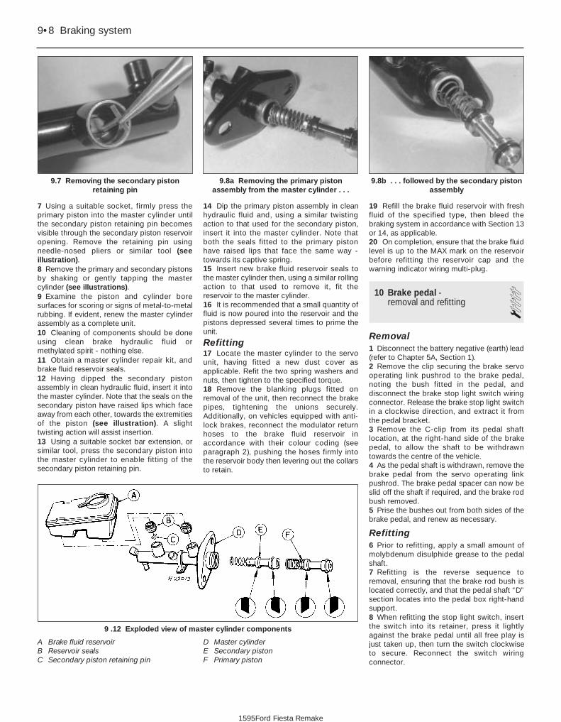
7 Using a suitable socket, firmly press theprimary piston into the master cylinder untilthe secondary piston retaining pin becomesvisible through the secondary piston reservoiropening. Remove the retaining pin usingneedle-nosed pliers or similar tool (seeillustration).8 Remove the primary and secondary pistonsby shaking or gently tapping the mastercylinder (see illustrations).9 Examine the piston and cylinder boresurfaces for scoring or signs of metal-to-metalrubbing. If evident, renew the master cylinderassembly as a complete unit.10 Cleaning of components should be doneusing clean brake hydraulic fluid ormethylated spirit - nothing else.11 Obtain a master cylinder repair kit, andbrake fluid reservoir seals.12 Having dipped the secondary pistonassembly in clean hydraulic fluid, insert it intothe master cylinder. Note that the seals on thesecondary piston have raised lips which faceaway from each other, towards the extremitiesof the piston (see illustration). A slighttwisting action will assist insertion.13 Using a suitable socket bar extension, orsimilar tool, press the secondary piston intothe master cylinder to enable fitting of thesecondary piston retaining pin.
14 Dip the primary piston assembly in cleanhydraulic fluid and, using a similar twistingaction to that used for the secondary piston,insert it into the master cylinder. Note thatboth the seals fitted to the primary pistonhave raised lips that face the same way -towards its captive spring.15 Insert new brake fluid reservoir seals tothe master cylinder then, using a similar rollingaction to that used to remove it, fit thereservoir to the master cylinder.16 It is recommended that a small quantity offluid is now poured into the reservoir and thepistons depressed several times to prime theunit.
Refitting17 Locate the master cylinder to the servounit, having fitted a new dust cover asapplicable. Refit the two spring washers andnuts, then tighten to the specified torque.18 Remove the blanking plugs fitted onremoval of the unit, then reconnect the brakepipes, tightening the unions securely.Additionally, on vehicles equipped with anti-lock brakes, reconnect the modulator returnhoses to the brake fluid reservoir inaccordance with their colour coding (seeparagraph 2), pushing the hoses firmly intothe reservoir body then levering out the collarsto retain.
19 Refill the brake fluid reservoir with freshfluid of the specified type, then bleed thebraking system in accordance with Section 13or 14, as applicable.20 On completion, ensure that the brake fluidlevel is up to the MAX mark on the reservoirbefore refitting the reservoir cap and thewarning indicator wiring multi-plug.
10 Brake pedal - removal and refitting 1
Removal1 Disconnect the battery negative (earth) lead(refer to Chapter 5A, Section 1).2 Remove the clip securing the brake servooperating link pushrod to the brake pedal,noting the bush fitted in the pedal, anddisconnect the brake stop light switch wiringconnector. Release the brake stop light switchin a clockwise direction, and extract it fromthe pedal bracket.3 Remove the C-clip from its pedal shaftlocation, at the right-hand side of the brakepedal, to allow the shaft to be withdrawntowards the centre of the vehicle.4 As the pedal shaft is withdrawn, remove thebrake pedal from the servo operating linkpushrod. The brake pedal spacer can now beslid off the shaft if required, and the brake rodbush removed.5 Prise the bushes out from both sides of thebrake pedal, and renew as necessary.
Refitting6 Prior to refitting, apply a small amount ofmolybdenum disulphide grease to the pedalshaft.7 Refitting is the reverse sequence toremoval, ensuring that the brake rod bush islocated correctly, and that the pedal shaft “D”section locates into the pedal box right-handsupport.8 When refitting the stop light switch, insertthe switch into its retainer, press it lightlyagainst the brake pedal until all free play isjust taken up, then turn the switch clockwiseto secure. Reconnect the switch wiringconnector.
9•8 Braking system
9 .12 Exploded view of master cylinder components
A Brake fluid reservoirB Reservoir sealsC Secondary piston retaining pin
D Master cylinderE Secondary pistonF Primary piston
9.8b . . . followed by the secondary pistonassembly
9.8a Removing the primary pistonassembly from the master cylinder . . .
9.7 Removing the secondary pistonretaining pin
1595Ford Fiesta Remake

11 Brake pedal-to-servo cross-link - removal and refitting 3
Removal1 Disconnect the battery negative (earth) lead(refer to Chapter 5A, Section 1).2 Disconnect the cross link pushrod from itsbrake pedal location by removing the retainingclip on the brake pedal, noting the bush fittedin the pedal.3 Disconnect the wiring multi-plug from thefluid level warning indicator in the mastercylinder reservoir filler cap, then remove thefiller cap. Note that the filler cap must not beinverted. The brake fluid should now beremoved from the reservoir.
4 Identify each brake pipe and its connectionto the master cylinder. Unscrew the fluid pipeto master cylinder union nuts and disconnectthe pipes. On models equipped with anti-lockbrakes, disconnect the modulator returnhoses from the brake fluid reservoir, collectingfluid spillage from the hoses in a suitable tray.The modulator return hose unions should bedisconnected by first pushing the hose intothe reservoir, then retaining the collar againstthe reservoir body whilst withdrawing thehose. Note that the modulator return hosesare colour coded - the left-hand modulatorhas a black return hose and connector, andshould be fitted to the forward section of thereservoir, whilst the right-hand modulator hasa grey return hose and connector, and shouldbe fitted to the rear section of the reservoir.5 Disconnect the vacuum hose from theservo unit by carefully levering between thehose connector and the servo housing collarwith a screwdriver.6 Lift up the flap of sound insulation on the
bulkhead, in the passenger side footwell, toexpose the servo mounting bracket retainingnuts, and remove them (see illustration).7 Remove the four nuts securing the servounit to its mounting bracket assembly.8 Pull the servo/master cylinder assemblyforward and remove the inner servo supportbracket.9 Remove the spring clip and clevis pinsecuring the servo actuating rod to the crosslink, then lift out the servo/master cylinderassembly.10 Remove the two nuts on the right-handside of the pedal box assembly to free thecross link right-hand support bracket, thenwithdraw the link from the vehicle (seeillustration).
Refitting11 Refitting is the reverse procedure toremoval, ensuring that the brake pedalpushrod grommet is seated correctly in thebulkhead and that the pushrod itself locatesthrough the brake pedal before securing theservo operating link support brackets. Ensurecorrect location of the pushrod bush in thebrake pedal.12 Bleed the complete brake hydraulicsystem in accordance with Section 13 or 14(as applicable).
12 Hydraulic pipes and hoses -renewal 2
Note: Before starting work, refer to thewarning at the beginning of Section 13concerning the dangers of hydraulic fluid.1 If any pipe or hose is to be renewed,minimise hydraulic fluid loss by disconnectingthe wiring multi-plug from the fluid levelwarning indicator in the master cylinderreservoir filler cap, then remove the filler cap.Note that the filler cap must not be inverted.Place a piece of plastic film over the reservoirand seal it with an elastic band. Alternatively,flexible hoses can be sealed, if required, usinga proprietary brake hose clamp; metal brake
pipe unions can be plugged (if care is takennot to allow dirt into the system) or cappedimmediately they are disconnected. Place awad of rag under any union that is to bedisconnected, to catch any spilt fluid.2 If a flexible hose is to be disconnected,unscrew the brake pipe union nut beforeremoving the spring clip which secures thehose to its mounting (see illustration). Wherethe other end of the hose is connecteddirectly to the brake caliper, disconnect it byunscrewing it from its tapped hole.3 To unscrew the union nuts, it is preferable toobtain a brake pipe spanner of the correct size;these are available from most large motoraccessory shops. Failing this, a close-fittingopen-ended spanner will be required, though ifthe nuts are tight or corroded, their flats may berounded-off if the spanner slips. In such a case,a self-locking wrench is often the only way tounscrew a stubborn union, but it follows thatthe pipe and the damaged nuts must berenewed on reassembly. Always clean a unionand surrounding area before disconnecting it. Ifdisconnecting a component with more thanone union, make a careful note of theconnections before disturbing any of them.4 If a brake pipe is to be renewed, it can beobtained, cut to length and with the unionnuts and end flares in place, from Forddealers. All that is then necessary is to bend itto shape, following the line of the original,before fitting it to the car. Alternatively, mostmotor accessory shops can make up brakepipes from kits, but this requires very carefulmeasurement of the original, to ensure thatthe replacement is of the correct length. Thesafest answer is usually to take the original tothe shop as a pattern.5 Before refitting, blow through the new pipeor hose with dry compressed air. Do notovertighten the union nuts. It is not necessaryto exercise brute force to obtain a sound joint.6 If flexible rubber hoses are renewed, ensurethat the pipes and hoses are correctly routed,with no kinks or twists, and that they aresecured in the clips or brackets provided.7 After fitting, bleed the hydraulic system asdescribed in Section 13 or 14 (as applicable),wash off any spilt fluid, and check carefully forfluid leaks.
Braking system 9•9
12.2 Prising out a spring retaining clipfrom a rigid pipe/flexible hose support
bracket11.10 Exploded view of brake pedal-to-
servo cross link and its retaining brackets11.6 Servo mounting bracket retaining
nuts
A Inner section retaining nutsB Outer section retaining nuts
9
1595Ford Fiesta Remake
An ideal way to remove fluidfrom the master cylinderreservoir is to use a cleansyringe or an old poultrybaster.

13 Hydraulic system - bleeding(conventional braking system) 3
Note: For vehicles equipped with an anti-lockbraking system, refer to Section 14.
Warning: Hydraulic fluid ispoisonous; wash offimmediately and thoroughly inthe case of skin contact, and
seek immediate medical advice if any fluidis swallowed or gets into the eyes. Certaintypes of hydraulic fluid are inflammable,and may ignite when allowed into contactwith hot components; when servicing anyhydraulic system, it is safest to assumethat the fluid IS inflammable, and to takeprecautions against the risk of fire asthough it is petrol that is being handled.Hydraulic fluid is also an effective paintstripper, and will attack plastics; if any isspilt, it should be washed off immediately,using copious quantities of clean water.Finally, it is hygroscopic (it absorbsmoisture from the air). The more moistureis absorbed by the fluid, the lower itsboiling point becomes, leading to adangerous loss of braking under hard use.Old fluid may be contaminated and unfitfor further use. When topping-up orrenewing the fluid, always use therecommended type, and ensure that itcomes from a freshly-opened sealedcontainer.1 The correct operation of any hydraulicsystem is only possible after removing all airfrom the components and circuit; and this isachieved by bleeding the system.2 During the bleeding procedure, add onlyclean, unused hydraulic fluid of therecommended type; never re-use fluid thathas already been bled from the system.Ensure that sufficient fluid is available beforestarting work.3 If there is any possibility of incorrect fluidbeing already in the system, the brakecomponents and circuit must be flushedcompletely with uncontaminated, correctfluid, and new seals should be fittedthroughout the system.4 If hydraulic fluid has been lost from thesystem, or air has entered because of a leak,ensure that the fault is cured beforeproceeding further.5 Park the vehicle on level ground, and applythe handbrake. Switch off the engine, then(where applicable) depress the brake pedalseveral times to dissipate the vacuum fromthe servo unit. Note: When bleeding thesystem, the vehicle must maintain a levelattitude, ie not tilted in any manner, to ensurethat air is not trapped within the pressurecontrol valves. During certain operations inthis manual, instructions are given to bleed thebrake hydraulic system with the front or therear of the vehicle raised. In such cases raisethe rest of the vehicle so that it maintains a
level attitude, but only if it is safe to do so. If itis not possible to achieve this safely, completethe remainder of the operation and bleed thebrake hydraulic system with the vehicle on itswheels.6 Check that all pipes and hoses are secure,unions tight and bleed screws closed.Remove the dust caps (where applicable), andclean any dirt from around the bleed screws.7 Disconnect the wiring multi-plug from thefluid level warning indicator in the mastercylinder reservoir filler cap, then remove thefiller cap. Note that the filler cap must not beinverted. Top-up the reservoir with thespecified fluid to the “Maximum” level (see“Weekly Checks”). Remember to maintain thefluid level at least above the “Minimum” levelline throughout the procedure, otherwisethere is a risk of further air entering thesystem.8 There are a number of one-man, do-it-yourself brake bleeding kits currently availablefrom motor accessory shops. It isrecommended that one of these kits is usedwhenever possible, as they greatly simplifythe bleeding operation, and also reduce therisk of expelled air and fluid being drawn backinto the system. If such a kit is not available,the basic (two-man) method must be used,which is described in detail below.9 If a kit is to be used, prepare the vehicle asdescribed previously, and follow the kitmanufacturer’s instructions, as the proceduremay vary slightly according to the type beingused; generally, they are as outlined below inthe relevant sub-section.10 Whichever method is used, the samesequence must be followed (paragraphs 11and 12) to ensure the removal of all air fromthe system.
Bleeding sequence11 If the system has been only partiallydisconnected, and suitable precautions weretaken to minimise fluid loss, it should benecessary to bleed only that part of thesystem (ie the primary or secondary circuit).12 If the complete system is to be bled, thenit is suggested that you work in the followingsequence:a) Right-hand front wheel.b) Left-hand rear wheel.c) Left-hand front wheel.d) Right-hand rear wheel.
Bleeding - basic (two-man)method13 Collect a clean glass jar, a suitable lengthof plastic or rubber tubing which is a tight fitover the bleed screw, and a ring spanner to fitthe screw. The help of an assistant will also berequired.14 Remove the dust cap from the first screwin the sequence (if not already done). Fit asuitable spanner and tube to the screw, placethe other end of the tube in the jar, and pour insufficient fluid to cover the end of the tube.15 Ensure that the master cylinder reservoir
fluid level is maintained at least above the“Minimum” level throughout the procedure.16 Have the assistant fully depress the brakepedal several times to build up pressure, thenmaintain it down on the final downstroke.17 While pedal pressure is maintained,unscrew the bleed screw (approximately oneturn) and allow the compressed fluid and air toflow into the jar. The assistant should maintainpedal pressure, following the pedal down tothe floor if necessary, and should not release the pedal until instructed to do so.When the flow stops, tighten the bleed screwagain. Have the assistant release the pedalslowly, and recheck the reservoir fluid level.18 Repeat the steps given in paragraphs 16and 17 until the fluid emerging from the bleedscrew is free from air bubbles. If the mastercylinder has been drained and refilled, and airis being bled from the first screw in thesequence, allow at least five seconds betweencycles for the master cylinder passages to refill.19 When no more air bubbles appear, tightenthe bleed screw securely, remove the tubeand spanner, and refit the dust cap (whereapplicable). Do not overtighten the bleedscrew.20 Repeat the procedure on the remainingscrews in the sequence, until all air isremoved from the system and the brake pedalfeels firm again.
Bleeding - using a one-wayvalve kit21 As their name implies, these kits consist ofa length of tubing with a one-way valve fitted,to prevent expelled air and fluid being drawnback into the system; some kits include atranslucent container, which can be positionedso that the air bubbles can be more easilyseen flowing from the end of the tube.22 The kit is connected to the bleed screw,which is then opened (see illustration). Theuser returns to the driver’s seat, depressesthe brake pedal with a smooth, steady stroke,and slowly releases it; this is repeated untilthe expelled fluid is clear of air bubbles.23 Note that these kits simplify work somuch that it is easy to forget the mastercylinder reservoir fluid level; ensure that this ismaintained at least above the “Minimum” levelat all times.
9•10 Braking system
13.22 Bleeding the hydraulic system usinga one-way valve kit
1595Ford Fiesta Remake
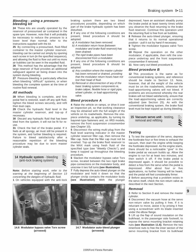
Bleeding - using a pressure-bleeding kit24 These kits are usually operated by thereservoir of pressurised air contained in thespare tyre. However, note that it will probablybe necessary to reduce the pressure to alower level than normal; refer to theinstructions supplied with the kit.25 By connecting a pressurised, fluid-filledcontainer to the master cylinder reservoir,bleeding can be carried out simply by openingeach screw in turn (in the specified sequence),and allowing the fluid to flow out until no moreair bubbles can be seen in the expelled fluid.26 This method has the advantage that thelarge reservoir of fluid provides an additionalsafeguard against air being drawn into thesystem during bleeding.27 Pressure-bleeding is particularly effectivewhen bleeding “difficult” systems, or whenbleeding the complete system at the time ofroutine fluid renewal.
All methods28 When bleeding is complete, and firmpedal feel is restored, wash off any spilt fluid,tighten the bleed screws securely, and refittheir dust caps.29 Check the hydraulic fluid level in themaster cylinder reservoir, and top-up ifnecessary.30 Discard any hydraulic fluid that has beenbled from the system; it will not be fit for re-use.31 Check the feel of the brake pedal. If itfeels at all spongy, air must still be present inthe system, and further bleeding is required.Failure to bleed satisfactorily after areasonable repetition of the bleedingprocedure may be due to worn mastercylinder seals.
14 Hydraulic system - bleeding(anti-lock braking system) 3
Note: Before starting work, refer to thewarning at the beginning of Section 13concerning the dangers of hydraulic fluid.1 On vehicles equipped with the anti-lock
braking system there are two bleedprocedures possible, depending on whichpart of the brake hydraulic system has beendisturbed.2 If any one of the following conditions arepresent, bleed procedure A should beadopted: a) A modulator has been removed.b) A modulator return hose (between
modulator and brake fluid reservoir) hasbeen drained.
c) The rigid brake pipes have beendisconnected from a modulator.
3 If any one of the following conditions arepresent, bleed procedure B should beadopted: a) Any condition where the master cylinder
has been removed or drained, providingthat the modulator return hoses have notlost their head of fluid.
b) Removal or disconnection of any of thebasic braking system components ie,brake caliper, flexible hose or rigid pipe,wheel cylinder, or load-apportioningvalve.
Bleed procedure A4 Raise the vehicle on ramps, or drive it overan inspection pit, so that working clearancemay be obtained with the full weight of thevehicle on its roadwheels. Remove the one-piece undertray, as applicable, by turning itsbayonet-type fasteners and, on XR2i models,remove the front suspension crossmember(see Chapter 10).5 Disconnect the wiring multi-plug from thefluid level warning indicator in the mastercylinder reservoir filler cap, then remove thefiller cap. Note that the filler cap must not beinverted. Top-up the brake fluid reservoir tothe MAX mark using fresh fluid of thespecified type (see “Weekly Checks”), andkeep it topped up throughout the bleedingprocedure.6 Slacken the modulator bypass valve Torxscrew, located between the two rigid brakepipe connections on the modulator body, andunscrew it two full turns (see illustration).7 Fully depress the auto-bleed plunger on themodulator and hold it down so that theplunger circlip contacts the modulator body(see illustration). With the plunger
depressed, have an assistant steadily pumpthe brake pedal at least twenty times whilstyou observe the fluid returning to the brakefluid reservoir. Continue this operation untilthe returning fluid is free from air bubbles.8 Release the auto-bleed plunger, ensuringthat it returns to its normal operationalposition - pull it out by hand if necessary.9 Tighten the modulator bypass valve Torxscrew.10 Repeat the operation on the othermodulator, if applicable, then refit the one-piece undertray and the front suspensioncrossmember if removed.11 Now carry out bleed procedure B.
Bleed procedure B12 This procedure is the same as forconventional braking systems, and referenceshould be made to Section 13. Note,however, that all the weight of the vehiclemust be on the roadwheels, otherwise theload-apportioning valves will not bleed. Ifproblems are encountered whereby the rearbrakes will not bleed satisfactorily, ensure thatthe load-apportioning valves are correctlyadjusted (see Section 25). As with theconventional braking system, the brake fluidlevel must be kept topped up during bleeding.
15 Vacuum servo unit - testing,removal and refitting 3
Testing1 To test the operation of the servo, depressthe footbrake four or five times to exhaust thevacuum, then start the engine while keepingthe footbrake depressed. As the engine starts,there should be a noticeable “give” in thebrake pedal as vacuum builds up. Allow theengine to run for at least two minutes, andthen switch it off. If the brake pedal isdepressed again, it should be possible todetect a hiss from the servo when the pedal isdepressed. After about four or fiveapplications, no further hissing will be heard,and the pedal will feel considerably firmer.2 Before assuming that a problem exists inthe servo itself, check the non-return valve asdescribed in the next Section.
Removal3 Refer to Section 9 and remove the mastercylinder.4 Disconnect the vacuum hose at the servonon-return valve by pulling it free. If it isreluctant to move, assist it by prising it freeusing a screwdriver with its blade insertedunder the elbow flange.5 Lift up the flap of sound insulation on thebulkhead, in the passenger side footwell, toexpose the servo mounting bracket retainingnuts (see illustration 11.6). Remove the twoinnermost nuts to free the inner section of theservo mounting bracket from its bulkhead
Braking system 9•11
14.7 Modulator auto-bleed plunger(arrowed)
14.6 Modulator bypass valve Torx screw(arrowed)
9
1595Ford Fiesta Remake

location. Slacken the other two nuts orremove them, as necessary.6 Remove the four nuts securing the servounit to its mounting bracket assembly, thenpull the servo forward to remove the innerservo support bracket (see illustration).7 Remove the spring clip and clevis pinsecuring the servo pushrod to the cross link,then lift out the servo unit (see illustration).8 Note that the servo unit cannot bedismantled for repair or overhaul and, if faulty,must be renewed.
Refitting9 Refitting is a reversal of removal. Refer toSection 9 for details of refitting the mastercylinder.
16 Vacuum servo unit vacuumhose and non-return valve -removal, testing and refitting
1Removal1 Depress the brake pedal three or four timesto exhaust any remaining vacuum from theservo unit.2 Carefully pull free and detach the servovacuum hose from the servo unit. If the hoseis reluctant to move, prise it free with the aidof a screwdriver, inserting its blade under theflange of the elbow.3 Detach the vacuum hose from its inletmanifold connection. Depending on the fixing,undo the union nut and withdraw the hose, orpress the hose and its retaining collarinwards, then holding the collar in, withdrawthe hose.4 If the hose or the fixings are damaged or inpoor condition, they must be renewed.
Non-return valve testing5 Examine the non-return valve for damageand signs of deterioration, and renew it ifnecessary. The valve may be tested byblowing through its connecting hoses in both directions. It should only be possible to blow from the servo end to the manifoldend.
Refitting6 Refitting is a reversal of removal. If fitting anew non-return valve, ensure that it is fittedthe correct way round.
17 Handbrake lever - removal and refitting 1
Removal1 Disconnect the battery negative (earth) lead(refer to Chapter 5A, Section 1), then chockthe wheels to secure the vehicle.2 Undo the bolts securing the front seats tothe floorpan, and remove both seats from thevehicle (see Chapter 11). Move the seats ontheir slide mechanisms to expose themounting bolts, as necessary.3 Remove the screws securing the rear seatcushion, then raise the cushion to obtainaccess to the carpet retaining screws.Remove the carpet retaining screws.4 Undo the bolt securing the seat belt clips tothe centre of the floorpan, then remove theclip assembly.5 Remove the seat belt lower anchor bracketbolt from its location at the base of the B-pillarbehind the driver’s seat.6 Remove the screws securing the sill scuffplate to the driver’s side of the vehicle, thencarefully pull the sill scuff plate away from itslocation so that the carpet is released.
7 Fold the carpet forwards, at the same timecarefully easing it out from under the sill scuffplate. Lift the carpet over the handbrake lever.8 Lift out the noise insulation for access tothe lever mounting bolts and the primarycable fixing.9 Fully release the handbrake lever, thenremove the handbrake primary cable clevispin securing clip (see illustration). Remove the clevis pin and withdraw theprimary cable from the handbrake leverassembly.10 Remove the cover (see illustration), thendisconnect the handbrake warning lightswitch wiring connection, and undo the twoscrews securing the switch to the handbrakelever assembly.11 Undo the handbrake lever mounting bolts,then withdraw the handbrake lever assemblyfrom the vehicle.
Refitting12 Refitting is the reverse procedure toremoval, ensuring that the handbrake warninglight wiring is routed away from the leverratchet. The loom should be secured to thefloorpan with tape.13 Check the handbrake adjustment asdescribed in Chapter 1 to complete.
18 Handbrake primary cable -removal and refitting 1
Removal1 Release the primary cable from thehandbrake lever, as described in the previousSection.2 Chock the front wheels then jack up therear of the car and support it on axle stands(see “Jacking and Vehicle Support”).3 Where applicable, detach the exhaustsystem and remove the heat shields from theunderside floorpan to allow access to theprimary cable connections underneath thevehicle (see Chapter 4E).4 Release the spring clip securing the pin,and extract the equaliser/cable pin. Detach
9•12 Braking system
17.10 Removing the cover from thehandbrake warning light switch
17.9 Removing the handbrake primarycable clevis pin securing clip
15.7 Spring clip (A) and clevis pin (B)securing servo pushrod to the cross link
15.6 Nuts securing servo unit to itsmounting bracket assembly (arrowed)
1595Ford Fiesta Remake

the equaliser from the primary cable (seeillustration).5 Remove the primary cable guide by driftingit out rearwards, through the floorpan, fromthe inside of the vehicle.
Refitting6 Refit in the reverse order of removal. Ensurethat the cable guide is secured in the floorpan,and lubricate the pivot pin with a liberalamount of high-melting-point grease.7 Refit the exhaust system and heat shieldswith reference to Chapter 4E (where applicable).8 Refer to Chapter 1 for details, and adjustthe handbrake as required before lowering thevehicle to the ground.
19 Handbrake rear cable -removal and refitting 2
Removal1 Chock the front wheels then jack up therear of the car and support it on axle stands(see “Jacking and Vehicle Support”). Fullyrelease the handbrake lever and remove therear roadwheels.2 Refer to the previous Section for details,and disconnect the handbrake primary cablefrom the equaliser.3 Disconnect the handbrake cable from itsadjuster body location and its fixed body
location (see illustration), then remove it fromits retaining clips.4 Remove the rear brake drum(s) and brakeshoes as described in Sections 5 and 6respectively.5 Compress the handbrake cable retainerlugs and release the cable from the backplate,then pull the cable through. Release the cablefrom the underbody fixings, and remove it from the vehicle.
Refitting6 Refitting is a reversal of the removalprocedure. Refer to Sections 6 and 5respectively for details on the refitting of thebrake shoes and drums.7 When the cable is fully refitted (but beforelowering the vehicle rear wheels to theground) check and adjust the handbrake asdescribed in Chapter 1.
20 Brake pressure controlvalves - removal and refitting 3
Note: Before starting work, refer to thewarning at the beginning of Section 13concerning the dangers of hydraulic fluid.
Removal1 The pressure control valves are located inthe engine compartment, fixed to the left-hand inner wing panel or screwed directly intothe master cylinder fluid outlet ports (seeillustrations).2 Minimise hydraulic fluid loss bydisconnecting the wiring multi-plug from the
fluid level warning indicator in the mastercylinder reservoir filler cap, then remove thefiller cap. Note that the filler cap must not beinverted. Place a piece of plastic film over thereservoir and seal it with an elastic band.Detach the rigid brake pipes from the valves.As the pipes are disconnected, tape over theexposed ends, or fit plugs, to prevent theingress of dirt and excessive fluid loss.3 To remove the inner wing panel mountedassembly, remove the two screws securingthe valve assembly mounting bracket to theinner wing panel, and withdraw the valveassembly from the vehicle. To remove thevalves from the bracket, slide free theretaining clips and detach the valve(s).4 To remove the master cylinder mountedvalves, unscrew them from the mastercylinder body.
Refitting5 Refitting is a reversal of the removalprocedure.6 On completion, bleed the completehydraulic system as described in Section 13.
21 Light-laden valve (Couriermodels) - removal andrefitting
3Note: Before starting work, refer to thewarning at the beginning of Section 13concerning the dangers of hydraulic fluid.
Removal1 For this operation, the vehicle must beraised for access underneath at the rear, butmust still be resting on its wheels. Suitableramps (or an inspection pit) will therefore berequired. If positioning the vehicle on a pair oframps, chock the front roadwheels.2 Minimise hydraulic fluid loss bydisconnecting the wiring multi-plug from thefluid level warning indicator in the mastercylinder reservoir filler cap, then remove thefiller cap. Note that the filler cap must not beinverted. Place a piece of plastic film over thereservoir and seal it with an elastic band.3 Disconnect the four brake pipes from thevalve, and drain any escaping fluid into asuitable container for disposal (seeillustration). Due to its location, care will be
Braking system 9•13
19.3 Handbrake rear cable fixed bodylocation
18.4 Handbrake equaliser yokearrangement
A Clevis pin securing clipB Clevis pinC Equaliser yokeD Primary cable guide
21.3 Hydraulic pipe and linkageattachments at the light-laden valve
20.1b Pressure control valves and pipeconnections at the master cylinder - later
models20.1a Pressure control valves located on
left-hand inner wing panel
9
1595Ford Fiesta Remake

needed not to spill the fluid onto the hands -wear suitable protective gloves. Plug or capthe disconnected pipes and valve openings,to prevent dirt ingress and further fluid loss.4 Unbolt the valve from its mounting bracket,unhook the linkage from the rear axle, thenwithdraw the valve (see illustration). Theintermediate bracket may be unbolted ifrequired.
Refitting5 Refitting is the reverse of the removalprocedure; adjust the valve as described inSection 22, then bleed the complete hydraulicsystem as described in Section 13. Check theoperation of the brakes before taking thevehicle out on the road.
22 Light-laden valve (Couriermodels) - adjustment 2
Note: To adjust the valve accurately, thevehicle must be at a known rear axle loading -owners who cannot determine the loadingwith sufficient accuracy must have this checkmade by a Ford dealer or similar expert.1 For this operation, the vehicle must beraised for access underneath at the rear, butmust be standing on its wheels. Suitableramps (or an inspection pit) will therefore berequired. If positioning the vehicle on a pair oframps, chock the front roadwheels.2 Measure the distance between the innerradius of the linkage’s hooked end and thefirst shoulder (see illustration). If thedimension is not as specified for the axleloading, adjustment is required.3 To adjust the setting, slacken the locknuton the valve linkage, move the rod until thesetting is correct, then tighten the locknutsecurely (see illustration). Check theoperation of the brakes before taking thevehicle out on the road.
23 Anti-lock braking system(ABS) - general information
A mechanically-driven, two-channel anti-lock braking system is available as a factory-fitted option on certain model variants withinthe Fiesta range.
The system comprises four maincomponents; two modulators, one for eachbrake circuit, and two rear axle load-apportioning valves, again, one for each brakecircuit. Apart from the additional hydraulicpiping, the remainder of the braking system isthe same as for conventional models.
The modulators are located in the enginecompartment with one mounted on each sideof the transmission, directly above thedriveshaft inner constant velocity joints. Eachmodulator contains a shaft which actuates aflywheel by means of a ball and ramp clutch.
A rubber toothed belt is used to drive themodulator shaft from the driveshaft innerconstant velocity joint.
During driving and under normal brakingthe modulator shaft and the flywheel rotatetogether and at the same speed through theengagement of a ball and ramp clutch. In thiscondition hydraulic pressure from the mastercylinder passes to the modulators and then toeach brake in the conventional way. In theevent of a front wheel locking the modulatorshaft rotation will be less than that of theflywheel and the flywheel will overrun the balland ramp clutch. This causes the flywheel toslide on the modulator shaft, move inward andoperate a lever which in turn opens a dumpvalve. Hydraulic pressure to the locked brakeis released via a de-boost piston allowing thewheel to once again revolve. Fluid passedthrough the dump valve is returned to themaster cylinder reservoir via the modulatorreturn hoses. At the same time hydraulicpressure from the master cylinder causes apump piston to contact an eccentric cam onthe modulator shaft. The flywheel is thendecelerated at a controlled rate by theflywheel friction clutch. When the speed of themodulator shaft and flywheel are once againequal the dump valve closes and the cyclerepeats. This complete operation takes placemany times a second until the vehicle stops orthe brakes are released.
The load-apportioning valves are mountedon a common bracket attached to the rearbody, just above the rear axle twist beamlocation, and are actuated by linkagesattached to the axle beam. The valvesregulate hydraulic pressure to the rear brakes,in accordance with vehicle load and attitude,so that the braking force available at the rearbrakes will always be lower than that availableat the front.
A belt-break warning switch is fitted to thecover which surrounds each modulatordrivebelt. The switch contains an arm which isin contact with the drivebelt at all times. If thebelt should break, or if the adjustment of the belt is too slack, the arm will move outclosing the switch contacts and informing thedriver via an instrument panel warning light.
24 Anti-lock braking system(ABS) components - removaland refitting
3ModulatorNote: Before starting work, refer to thewarning at the beginning of Section 13concerning the dangers of hydraulic fluid.1 Disconnect the battery negative (earth) lead(refer to Chapter 5A, Section 1).2 Minimise hydraulic fluid loss bydisconnecting the wiring multi-plug from thefluid level warning indicator in the mastercylinder reservoir filler cap, then remove thefiller cap. Note that the filler cap must not beinverted. Place a piece of plastic film over thereservoir and seal it with an elastic band.3 Disconnect the modulator return hosesfrom the master cylinder reservoir, collectingany fluid spillage from the hoses in a suitabletray. The modulator return hose unions shouldbe disconnected by first pushing the hose into the reservoir, then retaining the collaragainst the reservoir body whilst withdrawingthe hose. Note that the hoses are colourcoded - the left-hand modulator has a blackreturn hose and connector, and should befitted to the forward section of the reservoir,whilst the right-hand modulator has a greyreturn hose and connector, and should befitted to the rear section of the reservoir.
9•14 Braking system
22.3 Light-laden valve linkage adjustmentlocknut (arrowed)
22.2 Light-laden valve adjustment details
With rear axle load at 400 kg, “X” should be 147 mm
With rear axle load at 850 kg, “X” should be 166 mm
21.4 Light-laden valve mounting bolts(arrowed)
1595Ford Fiesta Remake

Right-hand side4 Chock the rear wheels then jack up thefront of the car and support it on axle stands(see “Jacking and Vehicle Support”).5 Remove the one-piece undertray wherefitted, by turning the bayonet type fasteners,and on XR2i models, remove the frontsuspension crossmember (see Chapter 10).6 From underneath, remove the belt-breakswitch from the right-hand drivebelt cover bysqueezing its release lever towards the mainbody of the switch (see illustration), thencarefully withdraw, ensuring that the beltcontact arm does not catch on the drivebeltcover.7 Remove the two bolts securing themodulator drivebelt cover to the modulatormounting bracket, and withdraw the cover(see illustration).8 Disconnect the rigid brake pipes from themodulator, fitting blanking plugs to preventexcessive fluid loss and dirt ingress.9 Remove the modulator pivot bolt andadjuster bolt (see illustration), then slip thedrivebelt from its pulley, and withdraw themodulator unit from the vehicle. Ensure thatthe modulator return hose does not becomekinked as the modulator unit is withdrawn.10 Disconnect the modulator return hosefrom the modulator unit, and fit a blankingplug to prevent dirt ingress. Allow for residualfluid spillage as the hose is disconnected.11 If a new modulator is to be fitted, note thatthese units are not interchangeable from sideto side, and the correct replacement must beobtained. The modulator units are colour-coded, and must be fitted with the arrows ontop of the casings pointing towards the frontof the vehicle.12 To refit, first connect the modulator returnhose to the return outlet on the modulatorunit.13 Locate the modulator unit to its bracketand fit the pivot bolt, having applied a thinsmear of anti-seize compound to the bolt, butdo not fully tighten at this stage. Take care notto damage the modulator return hose as it ismanoeuvred into position.14 Fit the drivebelt to its modulator pulleylocation, ensuring that it sits correctly over the
driveshaft pulley, then refit the adjuster boltbut do not fully tighten at this stage.15 Adjust the tension of the drivebelt bymoving the modulator unit, until a beltdeflection of 5.0 mm is obtained under firmfinger pressure. Check this using a ruler at apoint midway between the two pulleys.16 With the drivebelt tensioned correctly,tighten the pivot and adjuster bolts to thespecified torque. Re-check the tension of thedrivebelt after tightening the bolts.17 Reconnect the rigid brake pipes to themodulator, tightening the unions securely.18 Refit the modulator drivebelt cover to themodulator mounting bracket, and secure withits two retaining bolts.19 Refit the belt-break switch to themodulator drivebelt cover, taking care not todamage the belt contact arm as it passesthrough the cover.20 Reconnect the modulator return hose bypushing the hose firmly into its brake fluidreservoir location, then lever out the collar toretain it.21 Refit the front suspension crossmemberand the one-piece undertray, as applicable.22 Lower the vehicle to the ground.23 Top-up the brake fluid reservoir usingfresh fluid of the specified type (see “Weeklychecks”), then bleed the brake hydraulicsystem in accordance with Section 14. Refitthe reservoir filler cap and warning indicatorwiring multi-plug on completion.24 Reconnect the battery negative lead.
Left-hand side25 Repeat the procedures given inparagraphs 1 to 3.26 Chock the rear wheels then jack up thefront of the car and support it on axle stands(see “Jacking and Vehicle Support”). Removethe front roadwheels.27 Remove the one-piece undertray wherefitted, by turning the bayonet type fasteners,and on XR2i models, remove the frontsuspension crossmember (see Chapter 10).28 Remove the belt-break switch from theleft-hand drivebelt cover in a similar manner tothat described in paragraph 6, this time fromthe engine compartment.
29 Remove the two bolts securing themodulator drivebelt cover to the modulatormounting bracket, then ease the lower portionof the cover over the driveshaft taking carenot to damage the driveshaft CV joint gaiter.Withdraw the cover through the enginecompartment, manoeuvring it to clearobstructions.30 Disconnect the rigid brake pipes from themodulator, fitting blanking plugs to preventexcessive fluid loss and dirt ingress.31 Slacken the modulator pivot and adjusterbolts, then swing the modulator downwardsto release the drivebelt tension before slippingthe drivebelt from its modulator pulleylocation.32 Remove the modulator pivot and adjusterbolts, withdraw the modulator upwardsthrough the engine compartment. Ensure thatthe modulator return hose does not becomekinked as the modulator unit is withdrawn.33 Disconnect the modulator return hosefrom the modulator unit, and fit a blankingplug to prevent dirt ingress. Allow for residualfluid spillage as the hose is disconnected.34 If a new modulator is to be fitted, note thatthese units are not interchangeable from sideto side, and the correct replacement must beobtained. The modulator units are colour-coded, and must be fitted with the arrows ontop of the casings pointing towards the frontof the vehicle.35 To refit, first connect the modulator returnhose to the return outlet on the modulatorunit.36 Locate the modulator unit to its mountingbracket and fit the pivot bolt, having applied athin smear of anti-seize compound to the bolt,but do not fully tighten at this stage. Take carenot to damage the modulator return hose as itis manoeuvred into position.37 Fit the drivebelt to its modulator pulleylocation, ensuring that it sits correctly over thedriveshaft pulley, then refit the adjuster boltbut do not fully tighten at this stage.38 Adjust the tension of the drivebelt bymoving the modulator unit, until a beltdeflection of 5.0 mm is obtained under firmfinger pressure. Check this using a ruler at apoint midway between the two pulleys.
Braking system 9•15
24.9 Modulator pivot bolt (A) and adjusterbolt (B)
24.7 Modulator drivebelt cover tomounting bracket securing bolts (arrowed)
24.6 Belt-break switch in drivebelt cover
A Main switch body B Release lever
9
1595Ford Fiesta Remake

39 With the drivebelt tensioned correctly,tighten the pivot and adjuster bolts to thespecified torque. Re-check the tension of thedrivebelt after tightening the bolts.40 Reconnect the rigid brake pipes to themodulator, tightening the unions to seal thesystem.41 Refit the modulator drivebelt cover andsecure with its two retaining bolts. Take carenot to damage the driveshaft CV joint gaiter asthe cover is eased into position.42 Refit the belt-break switch to themodulator drivebelt cover, taking care not todamage the belt contact arm as it passesthrough the cover.43 Reconnect the modulator return hose bypushing the hose firmly into its brake fluidreservoir location, then lever out the collar toretain it.44 Refit the front suspension crossmemberand the one-piece undertray, as applicable.45 Refit the roadwheels, then remove theaxle stands and lower the vehicle to theground. Tighten the wheel nuts to thespecified torque.46 Top-up the brake fluid reservoir usingfresh fluid of the specified type (see “Weeklychecks”), then bleed the brake hydraulicsystem in accordance with Section 14. Refitthe reservoir filler cap and the warningindicator wiring multi-plug on completion.47 Reconnect the battery negative lead.
Modulator drivebelt48 Disconnect the battery negative (earth)lead (refer to Chapter 5A, Section 1).49 Chock the rear wheels then jack up thefront of the car and support it on axle stands(see “Jacking and Vehicle Support”). Removethe relevant front roadwheel.50 Remove the one-piece undertray wherefitted, by turning its bayonet-type fasteners,and on XR2i models, remove the frontsuspension crossmember (see Chapter 10).51 Remove the belt-break switch from therelevant drivebelt cover, then remove thedrivebelt cover, as described in the previoussub-Section.52 Slacken the modulator pivot and adjusterbolts to release drivebelt tension, then slip thedrivebelt from the modulator.53 Remove the track rod end balljoint fromthe steering arm on the spindle carrier (seeChapter 10).54 Disconnect the anti-roll bar connectinglink (where applicable) and release the brakehose from their locations on the suspensionstrut.55 Remove the pinch bolt and nut securingthe lower suspension arm balljoint to thespindle carrier, and separate the balljoint fromthe spindle carrier assembly.56 To release the driveshaft inner CV jointfrom the differential, have an assistant pull thespindle carrier away from the centre of thevehicle whilst you insert a lever between theinner CV joint and the transmission casing,then firmly strike the lever with the flat of the
hand, but be careful not to damage adjacentcomponents. Make provision for escapingtransmission oil, if possible plugging theopening to prevent excessive loss. Do notallow the CV joints to bend more than 20°from the horizontal or internal damage mayoccur. If both driveshafts are to be removed,immobilise the differential by inserting an oldjoint or suitable shaft, before the otherdriveshaft is removed.57 Slide the drivebelt off the driveshaft.58 Remove the snap-ring from the groove inthe splines of the inner CV joint. This snap-ring must be renewed every time thedriveshaft is withdrawn from the differential.59 With the drivebelt removed, closelyexamine the condition of the belt over itsentire length. Renew the belt if any cracks arenoticed in the fabric at the roots of the teeth, ifthere is any abrasion of the fabric facingmaterial, or if there are any tears starting fromthe edge of the belt.60 If, since the drivebelts were last renewed,a vehicle has covered more than 30 000 miles(48 000 km) or a period of more than twoyears has elapsed, the drivebelts should berenewed as a matter of course.61 Prior to refitting the drivebelt, thoroughlyclean its CV joint pulley location.62 Fit the drivebelt over the driveshaft then,with a new snap-ring fitted to the inner CVjoint splines, lubricate the splines withtransmission oil. Remove the temporary plugand insert the inner CV joint to itstransmission casing location. Press againstthe spindle carrier so that the snap-ringengages fully to hold the CV joint splines inthe differential.63 Refitting is now a reversal of the removalprocedure, tensioning the drivebelt asdescribed in the previous sub-Section. Ensurethat the pinch-bolt securing the lowersuspension arm balljoint to the spindle carrierlocates in the annular groove on the balljointspindle. Secure the track rod and balljoint,using a new split pin. Tighten the suspensioncomponents to their specified torque (seeChapter 10).64 Check the level of the transmission oil,and top-up as required (see Chapter 1).
Modulator belt-break switch65 Modulator belt-break switches are fittedto each of the two drivebelt covers, and clipinto position. To remove, gently squeeze theprotruding lever on the switch towards themain switch body and lift out, ensuring thatthe belt contact arm does not catch on thedrivebelt cover.
25 Load-apportioning valve(ABS models) - adjustment 3
1 Before attempting to adjust the load-apportioning valves, the vehicle must be at itskerb weight, ie with approximately half a tankof fuel and carrying no load. Note that aspecial setting tool will be required to adjustthe valves - this can be fabricated, to thedimensions shown (see illustration).2 Raise the vehicle on ramps or drive it overan inspection pit, so that working clearance isobtained with the full weight of the vehicleresting on its roadwheels. Remove the sparewheel and its carrier.3 To check adjustment, insert the load-apportioning valve setting tool into the nylonsleeve without pre-loading the valve. If unableto insert the tool, carry out the followingadjustment procedure.4 Slacken the operating link adjustment fixingscrew then insert the setting tool into thenylon sleeve, applying light pressure to theoperating link upper arm, so that the settingtool fully locates. With the setting tool justresting up against the adjustment post,tighten the operating link adjustment fixingscrew to the specified torque (seeillustration).5 Repeat the procedure on the other valve.6 Refit the spare wheel on completion.
26 Load-apportioning valve(ABS models) - removal andrefitting
31 Minimise hydraulic fluid loss bydisconnecting the wiring multi-plug from thefluid level warning indicator in the master
9•16 Braking system
25.4 Load-apportioning valve adjustment
A Setting toolB Operating link adjustment fixing screwC Adjustment post
25.1 Load-apportioning valve adjustmenttool (dimensions given in mm)
1595Ford Fiesta Remake

cylinder reservoir filler cap, then remove thefiller cap. Note that the filler cap must not beinverted. Place a piece of plastic film over thereservoir and seal it with an elastic band.2 Raise the vehicle on ramps, or drive it overan inspection pit, so that working clearancemay be obtained with the full weight of thevehicle on its roadwheels.3 Remove the spare wheel and its carrier foraccess to the load-apportioning valves (seeillustration).4 Disconnect the load-apportioning valveoperating links from the rear axle twist beam,by undoing the nuts securing them.5 Disconnect the rigid brake pipes from theload-apportioning valves, and fit blanking plugsto prevent dirt ingress. Make provision forescaping fluid as the pipes are disconnected.
6 Remove the bolts securing the valveassembly mounting bracket to the vehicle body, then carefully lower from thevehicle.7 The valves can now be individually removedfrom the mounting bracket, as required, byundoing the fixings securing them from theother side of the bracket.8 Refitting is the reverse sequence toremoval, adjusting the load-apportioningvalves, as described in the previous Section,before refitting the spare wheel. When fitting anew valve, the plastic tie must be cut offbefore attempting any adjustment, and thesetting tool must be used as described in theprevious Section.9 Bleed the brake hydraulic system inaccordance with Section 14.
Braking system 9•17
26.3 General view of load-apportioningvalve arrangement (spare wheel and
carrier removed for access)
9
1595Ford Fiesta Remake

9•18 Braking system
1595Ford Fiesta Remake
Notes

10
1595Ford Fiesta Remake
Wheel alignment and steering anglesFront wheel toe setting:
Pre-1990 models:Tolerance allowed before resetting required . . . . . . . . . . . . . . . . . 3.0 mm toe-out to 3.0 mm toe-in (0°30’ toe-out to 0°30’ toe-in)Adjustment setting (if required) . . . . . . . . . . . . . . . . . . . . . . . . . . . . Parallel ± 1.0 mm (0° ± 0°10’)
1990 models onward:All models except Turbo:
Tolerance allowed before resetting required . . . . . . . . . . . . . . . . 4.5 mm toe-out to 0.5 mm toe-in (0°45’ toe-out to 0°05’ toe-in)Adjustment setting (if required) . . . . . . . . . . . . . . . . . . . . . . . . . . 2.0 mm toe-out ± 1.0 mm (0°20’ toe-out ± 0°10’)
Turbo models:Tolerance allowed before resetting required . . . . . . . . . . . . . . . . 4.0 mm toe-out to parallel (0°40’ toe-out to 0°0’)Adjustment setting (if required) . . . . . . . . . . . . . . . . . . . . . . . . . . 2.0 mm toe-out ± 1.0 mm (0°20’ toe-out ± 0°10’)
Chapter 10Suspension and steering
Auxiliary drivebelt check and renewal . . . . . . . . . . . . . . .See Chapter 1Front hub bearings - renewal . . . . . . . . . . . . . . . . . . . . . . . . . . . . . . 3Front spindle carrier - removal and refitting . . . . . . . . . . . . . . . . . . . 2Front suspension anti-roll bar - removal and refitting . . . . . . . . . . . . 6Front suspension crossmember - removal and refitting . . . . . . . . . . 7Front suspension lower arm - removal and refitting . . . . . . . . . . . . . 8Front suspension strut - dismantling, examination and reassembly . . 5Front suspension strut - removal and refitting . . . . . . . . . . . . . . . . . 4General information . . . . . . . . . . . . . . . . . . . . . . . . . . . . . . . . . . . . . . 1Power steering fluid cooler - removal and refitting . . . . . . . . . . . . . . 26Power steering fluid level check . . . . . . . . . . . . .See “Weekly Checks”Power steering hydraulic system - bleeding . . . . . . . . . . . . . . . . . . . 27Power steering pump - removal and refitting . . . . . . . . . . . . . . . . . . 25Rear axle (all models except Courier) - removal and refitting . . . . . . 12Rear axle pivot bushes (all models except Courier) - renewal . . . . . 13Rear hub bearings - renewal . . . . . . . . . . . . . . . . . . . . . . . . . . . . . . . 9Rear shock absorber (Courier models) - removal, examination
and refitting . . . . . . . . . . . . . . . . . . . . . . . . . . . . . . . . . . . . . . . . . . 16
Rear strut (all models except Courier) - dismantling, examinationand reassembly . . . . . . . . . . . . . . . . . . . . . . . . . . . . . . . . . . . . . . . 11
Rear strut (all models except Courier) - removal and refitting . . . . . 10Rear suspension anti-roll bar (all models except Courier) -
removal and refitting . . . . . . . . . . . . . . . . . . . . . . . . . . . . . . . . . . . 14Rear suspension assembly (Courier models) - removal and refitting . . 17Rear suspension components (Courier models) - general . . . . . . . . 15Rear suspension ride height (Courier models) - adjustment . . . . . . . 18Steering column (manual steering) - removal and refitting . . . . . . . . 20Steering column (power steering) - removal and refitting . . . . . . . . . 21Steering gear (manual steering) - removal and refitting . . . . . . . . . . 23Steering gear (power steering) - removal and refitting . . . . . . . . . . . 24Steering gear rubber gaiters - renewal . . . . . . . . . . . . . . . . . . . . . . . 22Steering wheel - removal and refitting . . . . . . . . . . . . . . . . . . . . . . . 19Suspension and steering check . . . . . . . . . . . . . . . . . . .See Chapter 1Track rod end balljoint - removal and refitting . . . . . . . . . . . . . . . . . 28Tyre condition and pressure checks . . . . . . . . . .See “Weekly Checks”Wheel alignment and steering angles - general information . . . . . . . 29
10•1
Specifications
Contents
Easy, suitable fornovice with littleexperience
Fairly easy, suitablefor beginner withsome experience
Fairly difficult,suitable for competentDIY mechanic
Difficult, suitable forexperienced DIYmechanic
Very difficult,suitable for expert DIYor professional
Degrees of difficulty
54321
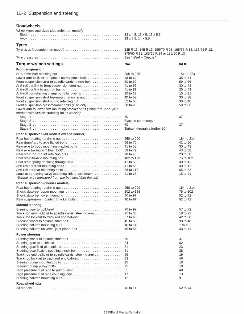
RoadwheelsWheel types and sizes (dependent on model):
Steel . . . . . . . . . . . . . . . . . . . . . . . . . . . . . . . . . . . . . . . . . . . . . . . . . . 13 x 4.5, 13 x 5, 13 x 5.5Alloy . . . . . . . . . . . . . . . . . . . . . . . . . . . . . . . . . . . . . . . . . . . . . . . . . . 13 x 5.5, 14 x 5.5
TyresTyre sizes (dependent on model) . . . . . . . . . . . . . . . . . . . . . . . . . . . . . . 135 R 13, 145 R 13, 155/70 R 13, 165/55 R 13, 165/65 R 13,
175/60 R 13, 185/55 R 14 or 185/60 R 13Tyre pressures . . . . . . . . . . . . . . . . . . . . . . . . . . . . . . . . . . . . . . . . . . . . See “Weekly Checks”
Torque wrench settings Nm lbf ft
Front suspensionHub/driveshaft retaining nut . . . . . . . . . . . . . . . . . . . . . . . . . . . . . . . . . . 205 to 235 151 to 173Lower arm balljoint-to-spindle carrier pinch bolt . . . . . . . . . . . . . . . . . . 48 to 60 35 to 44Front suspension strut to spindle carrier pinch-bolt . . . . . . . . . . . . . . . 80 to 90 59 to 66Anti-roll bar link to front suspension strut nut . . . . . . . . . . . . . . . . . . . . 41 to 58 30 to 43Anti-roll bar link to anti-roll bar nut . . . . . . . . . . . . . . . . . . . . . . . . . . . . . 41 to 58 30 to 43Anti-roll bar retaining clamp bolts to lower arm . . . . . . . . . . . . . . . . . . . 20 to 28 15 to 21Front suspension strut top-mount retaining nut . . . . . . . . . . . . . . . . . . . 40 to 52 30 to 38Front suspension strut spring retaining nut . . . . . . . . . . . . . . . . . . . . . . 52 to 65 38 to 48Front suspension crossmember bolts (XR2i only) . . . . . . . . . . . . . . . . . 80 to 90 59 to 66Lower arm to lower arm mounting bracket bolts (using torque-to-yieldmethod with vehicle standing on its wheels):
Stage 1 . . . . . . . . . . . . . . . . . . . . . . . . . . . . . . . . . . . . . . . . . . . . . . . . 50 37Stage 2 . . . . . . . . . . . . . . . . . . . . . . . . . . . . . . . . . . . . . . . . . . . . . . . . Slacken completelyStage 3 . . . . . . . . . . . . . . . . . . . . . . . . . . . . . . . . . . . . . . . . . . . . . . . . 50 37Stage 4 . . . . . . . . . . . . . . . . . . . . . . . . . . . . . . . . . . . . . . . . . . . . . . . . Tighten through a further 90°
Rear suspension (all models except Courier)Rear hub bearing retaining nut . . . . . . . . . . . . . . . . . . . . . . . . . . . . . . . . 250 to 290 184 to 214Rear drum/hub to axle flange bolts . . . . . . . . . . . . . . . . . . . . . . . . . . . . 56 to 76 41 to 56Rear axle to body mounting bracket bolts . . . . . . . . . . . . . . . . . . . . . . . 41 to 58 30 to 43Rear axle trailing arm bush bolt* . . . . . . . . . . . . . . . . . . . . . . . . . . . . . . . 58 to 79 43 to 58Rear strut top-mount retaining nuts . . . . . . . . . . . . . . . . . . . . . . . . . . . . 28 to 40 20 to 30Rear strut-to-axle mounting bolt . . . . . . . . . . . . . . . . . . . . . . . . . . . . . . 102 to 138 75 to 102Rear strut spring retaining through-bolt . . . . . . . . . . . . . . . . . . . . . . . . . 41 to 58 30 to 42Anti-roll bar front mounting bolts . . . . . . . . . . . . . . . . . . . . . . . . . . . . . . 41 to 58 30 to 42Anti-roll bar rear mounting bolts . . . . . . . . . . . . . . . . . . . . . . . . . . . . . . . 88 to 113 65 to 83Load-apportioning valve operating link to axle beam . . . . . . . . . . . . . . 21 to 28 15 to 21*Torque to be measured from the bolt head (not the nut)
Rear suspension (Courier models)Rear hub bearing retaining nut . . . . . . . . . . . . . . . . . . . . . . . . . . . . . . . . 250 to 290 184 to 214Shock absorber upper mounting . . . . . . . . . . . . . . . . . . . . . . . . . . . . . . 102 to 138 75 to 102Shock absorber lower mounting . . . . . . . . . . . . . . . . . . . . . . . . . . . . . . 70 to 97 52 to 72Rear suspension mounting bracket bolts . . . . . . . . . . . . . . . . . . . . . . . . 70 to 97 52 to 72
Manual steeringSteering gear to bulkhead . . . . . . . . . . . . . . . . . . . . . . . . . . . . . . . . . . . 70 to 97 57 to 72Track rod end balljoint to spindle carrier steering arm . . . . . . . . . . . . . . 25 to 30 18 to 22Track rod locknut to track rod end balljoint . . . . . . . . . . . . . . . . . . . . . . 57 to 68 42 to 50Steering wheel to column shaft bolt . . . . . . . . . . . . . . . . . . . . . . . . . . . . 45 to 55 33 to 40Steering column mounting nuts . . . . . . . . . . . . . . . . . . . . . . . . . . . . . . . 10 to 14 7 to 10Steering column universal joint pinch-bolt . . . . . . . . . . . . . . . . . . . . . . . 45 to 56 33 to 41
Power steeringSteering wheel to column shaft bolt . . . . . . . . . . . . . . . . . . . . . . . . . . . . 50 37Steering gear to bulkhead . . . . . . . . . . . . . . . . . . . . . . . . . . . . . . . . . . . 84 62Steering gear fluid pipe unions . . . . . . . . . . . . . . . . . . . . . . . . . . . . . . . . 31 23Steering gear flexible coupling pinch-bolt . . . . . . . . . . . . . . . . . . . . . . . 51 38Track rod end balljoint to spindle carrier steering arm . . . . . . . . . . . . . . 26 19Track rod locknut to track rod end balljoint . . . . . . . . . . . . . . . . . . . . . . 63 46Steering pump mounting bolts . . . . . . . . . . . . . . . . . . . . . . . . . . . . . . . . 25 18Steering pump pulley bolts . . . . . . . . . . . . . . . . . . . . . . . . . . . . . . . . . . . 25 18High pressure fluid pipe to pump union . . . . . . . . . . . . . . . . . . . . . . . . . 65 48High pressure fluid pipe coupling joint . . . . . . . . . . . . . . . . . . . . . . . . . . 17 13Steering column mounting nuts . . . . . . . . . . . . . . . . . . . . . . . . . . . . . . . 12 9
Roadwheel nutsAll models . . . . . . . . . . . . . . . . . . . . . . . . . . . . . . . . . . . . . . . . . . . . . . . . 70 to 110 52 to 74
10•2 Suspension and steering
1595Ford Fiesta Remake

1 General information
The front suspension is of independenttype, achieved by the use of MacPhersonstruts (see illustration). The struts, whichincorporate coil springs and integral shockabsorbers, are located at their uppermountings by rubber insulators and securedto the inner wing panels by cup seatmountings and locknuts. The lower end ofeach strut is bolted to the top of a cast spindlecarrier. The spindle carriers house non-adjustable hub bearings as a variation of aproven design. The lower mountings of thespindle carriers are attached, via balljoints, toa pressed-steel lower arm assembly. Thelower arm assembly consists of two sections.The lower arm mounting bracket is boltedsecurely to the underside of the vehicle, andhas a locating peg and unique outer fixing boltto ensure correct location. The A-shapedlower arm is attached to its mounting bracketby double vertical bushes and controls bothlateral and fore and aft movement of the frontwheels. The balljoints connecting the lowermountings of the spindle carriers to the lower arms are riveted to the lower arms, andare not available as separate service items. Ananti-roll bar is fitted to high specificationmodels and, additionally on the XR2i, a frontsuspension crossmember is fitted.
On all models except Courier, the rearsuspension is semi-independent, with aninverted V-section beam welded betweentubular trailing arms (see illustration). Thisinverted V-section beam allows a limitedtorsional flexibility, giving each rear wheel acertain degree of independent movement,whilst maintaining optimum track and wheelcamber control. This type of arrangement iscalled a “twist beam” rear axle. The axle isattached to the body by rubber void bushes,through brackets bolted to the underside ofthe vehicle. Each bracket has a conicallocating peg to ensure accurate alignment ofthe axle assembly. The rear suspension struts,which are similar to the MacPherson strutsused at the front, are mounted at their upperends by nut and captive bolt fixings throughthe suspension turrets in the luggagecompartment. At their lower ends, the strutsare attached, close to the wheels, by boltspassed through the trailing arms and lowerstrut integral bushes. The rear wheelhub/brake drum unit and spindle on each sideform an assembly which can be unbolted fromthe axle without disturbing the hub bearings.An anti-roll bar is fitted to the rear suspensionon certain later models.
Courier models are fitted with a modifiedversion of the twist beam rear axle, usinglinked torsion bars as springs and to provideanti-roll stabilisation (see illustration).Separate shock absorbers are fitted to controlsuspension movement.
Suspension and steering 10•3
1.1 General view of front suspension components
1.3 General view of rear suspension components (Courier models)
1.2 General view of rear suspension components (all models except Courier)
10
1595Ford Fiesta Remake
A Anti-roll barB Anti-roll bar connecting linkC Anti-roll bar suspension strut bracketD Anti-roll bar bush and clamp bracketE Coil spring and suspension strut
assemblyF Spindle carrierG Lower suspension armH Lower suspension arm mounting bracketI Front suspension (bracing) crossmember
(XR2i only)
A Twist beam rear axleB Coil spring and
suspension strutassembly
C Mounting bracketD Void bushE Brake drum, wheel
hub and spindleassembly
A Pivot bracketsB Rear axleC Rear (anti-roll) torsion barsD Connecting linkE Front (spring) torsion bars

On all models, the steering is ofconventional rack-and-pinion type,incorporating a safety system of convolutedcolumn tube and double universally-jointedlower steering shaft links.
The steering column tube is supported at itsupper end by bracketry, and at its lower end bya nylon support bush. The steering shaft issupported within the column tube by twosupport bearings, one at either end of the tube.
The steering rack assembly is located onthe bulkhead. Steering input is transmitted,via the steering shaft, to the pinion whichmeshes with the teeth on the rack.
The pinion transferring the steering inputmoves the rack within its housing tube,withdrawing and extending the track rodsattached to either end of the rack by balljoints.This movement is transferred, by balljoints inthe track rod ends, to the steering arms on the
spindle carriers which direct the roadwheels.From the 1994 model year onwards, power
steering is available as standard or optionalequipment on certain models.
2 Front spindle carrier -removal and refitting 3
RemovalNote: A new hub/driveshaft retaining nut willbe required for refitting.1 Remove the wheel trim from the frontroadwheel on the side concerned, then usinga small pin punch, peen back the lockingportion of the front hub/driveshaft nut. Loosenoff the nut about half-a-turn.2 Loosen off the front roadwheel retainingnuts on the side concerned.3 Chock the rear wheels then jack up thefront of the car and support it on axle stands(see “Jacking and Vehicle Support”). Removethe appropriate roadwheel, and unscrew andremove the hub/driveshaft retaining nut andwasher.4 Unscrew the retaining bolt and detach thebrake hose and its locating bracket from thesuspension strut (see illustration).5 Undo the two retaining bolts, and removethe brake caliper and anchor bracket from thespindle carrier. Support the caliper bysuspending it from above, to prevent thehydraulic hose from being strained or distorted.
6 Remove the single screw securing thebrake disc to the hub, and slide the disc offthe wheel studs.7 On pre-June 1990 models, fabricate ahome-made bracket to secure the wheel huband brake disc to the spindle carrier (seeillustration). Retain the bracket at one endwith a wheel nut and at the other end with abrake caliper retaining bolt. This will preventthe hub and disc from becoming detachedfrom the spindle carrier (with possible damageto the hub bearings) when the driveshaft isremoved. On later models the hub is aninterference fit in the bearing inner races andis unlikely to become detached. 8 Where an anti-roll bar is fitted, undo the nutsecuring the connecting link to thesuspension strut bracket, and separate thelink from the strut bracket.9 Detach the track rod end balljoint from thesteering arm on the side concerned asdescribed in Section 28.10 Remove the pinch-bolt securing thespindle carrier to the suspension strut (seeillustration).11 Remove the Torx-head pinch-bolt and nutsecuring the lower suspension arm balljoint tothe spindle carrier. Prise open the joint using alarge screwdriver and detach the balljoint fromthe spindle carrier unit (see illustrations).12 Using a small crowbar with a thin tip, or astout screwdriver as an alternative, lever thespindle carrier slot to separate the spindlecarrier from the suspension strut (seeillustration). Lower the spindle carrier slightly
10•4 Suspension and steering
2.12 Separate the spindle carrier from thestrut
2.11c . . . and detach the lower armballjoint from the spindle carrier
2.11b . . . prise open the joint . . .
2.11a Remove the lower arm-to-spindlecarrier pinch bolt and nut . . .
2.10 Remove the suspension strut-to-spindle carrier pinch bolt
2.7 Securing the hub to the spindle carrierusing a home-made bracket
2.4 Disconnect the brake hose from thefront suspension strut
1595Ford Fiesta Remake

(tapping it down with a soft-faced mallet ifnecessary) and carefully pull it off thedriveshaft, having supported the driveshaft toprevent damage to the CV joints - thedriveshaft must not be bent at an anglegreater than 20° from the horizontal. If thedriveshaft is tight in the hub, lightly tap itsouter end with a soft-faced hammer, or use aconventional puller and spacer to free it.Remove the dust sleeve from the inner rimgroove of the spindle carrier.
Refitting13 Fit the dust sleeve to its groove, thenlocate the spindle carrier over the driveshaft.Draw the driveshaft CV joint through the hubusing the old retaining nut and washer.14 Lever the spindle carrier slot open andrefit the spindle carrier to the suspensionstrut. Remove the lever, refit the pinch-boltand tighten it to the specified torque.15 Fit a new hub/driveshaft nut and washer,and tighten the nut as much possible at thisstage. As the nut is being tightened, rotate thehub to ensure that the bearings seat correctly.16 Refit the track rod end balljoint to thesteering arm on the spindle carrier, tighten thenut to the specified torque and insert a newsplit-pin to secure.17 Reconnect the lower suspension armballjoint to the spindle carrier, refit the pinch-bolt and nut, and tighten to the specifiedtorque. Note that the bolt must locate in theannular groove on the ballstud (seeillustration).18 Remove the bracket securing the hub tothe spindle carrier (where applicable), refit thebrake disc and tighten the single screwsecuring the disc to the hub.19 Refit the brake caliper and anchor bracketto the spindle carrier, tightening the bolts tothe specified torque (see Chapter 9).20 Refit the bolt securing the brake hosebracket to the front suspension strut.21 Where an anti-roll bar is fitted, refit theconnecting link to the suspension strutbracket.22 Refit the roadwheel, lower the vehicle tothe ground, then tighten the hub nut to thespecified torque. Using a pin punch, stake-
lock the nut in the groove in the end of theaxle stub.23 Tighten the roadwheel nuts to thespecified torque setting.
3 Front hub bearings - renewal 4
Note: The front hub bearings should only beremoved from the spindle carrier if they are tobe renewed. The removal procedure rendersthe bearings unserviceable, and they must notbe re-used. Prior to dismantling, it should benoted that a hub/bearing puller and anassortment of metal tubes of variousdiameters (and preferably, a press) will berequired. Unless these tools are available, therenewal of the hub bearings will have to beentrusted to a Ford garage. Under nocircumstances attempt to tap the hubbearings into position, as this will render themunserviceable.
Pre-June 1990 models1 Remove the spindle carrier from the vehicleas described in Section 2.2 Remove the home-made bracket used toretain the hub in place and slide the hub out ofthe spindle carrier assembly.3 Securely support the spindle carrier in avice with its inner face uppermost.4 Using a suitable punch, tap the outerbearing outer race at diametrically-opposedpoints and remove the bearing assembly fromthe spindle carrier (see illustration). Do notallow the bearing to tilt during its withdrawalfrom the housing, or it will jam and possiblydamage the surface of the bore. Any burrs leftin a bearing bore will prevent the new bearingfrom seating correctly.5 Turn the spindle carrier over and removethe inner bearing assembly in the same way.6 Thoroughly clean the bearing bore and hub,then secure the spindle carrier in the vice in anupright position.7 Press the new outer bearing assembly intothe spindle carrier using a length of metal tubeof diameter slightly less than the outer race.
Do not apply any pressure to the inner race.Alternatively, a long threaded rod or bolt, a nutand large flat washers may be used to drawthe bearing into position (see illustration).Once the bearing has been installed, take carenot to dislodge the inner race and seal.8 Using the same method as for the outerbearing, draw in the new inner bearingassembly from the other side of the spindlecarrier. Again, take care not to dislodge theinner race and seal once the bearing is inposition.9 Support the inner bearing inner race on alength of metal tube, and draw the hub fullyinto the bearings using the same toolingarrangement as before. It may even bepossible to insert the hub using firm handpressure only, but make sure that the innerbearing inner race is well supported.10 Fit the home-made bracket to secure thehub into the spindle carrier, dismantling theservice tools or equivalent as necessary.Ensure that the hub and spindle carrier do notbecome separated at any time, as this willdisplace the bearings seals and lead topremature bearing failure.11 The assembly can now be refitted to thevehicle, as described in the previous Section.
June 1990 models onwardNote: On these later models, the bearing’sinner races are an interference fit on the hub.During removal of the hub from the spindlecarrier, the outer bearing inner race will remainin position on the hub and a knife-edgedbearing puller will be required to remove it.12 Remove the spindle carrier from thevehicle as described in Section 2.13 The hub must now be removed from thebearing inner races. It is preferable to use apress to do this, but it is possible to drive outthe hub using a length of metal tube ofsuitable diameter.14 Part of the inner race will remain on thehub, and this should be removed using aknife-edged puller.15 Securely support the spindle carrier in avice with its inner face uppermost.
Suspension and steering 10•5
3.7 Using home-made tools to fit the outerbearing assembly to the spindle carrier
A Steel tubeB Spindle carrierC Bearing
D Steel tubeE Flat washerF Threaded bolt
3.4 Using a punch to remove the hubbearing outer race from the spindle carrier
2.17 Lower suspension arm balljointshowing annular groove (arrowed)
10
1595Ford Fiesta Remake

16 Using a suitable punch, tap the outerbearing outer race at diametrically-opposedpoints and remove the bearing assembly fromthe spindle carrier. Do not allow the bearing totilt during its withdrawal from the housing, or itwill jam and possibly damage the surface ofthe bore. Any burrs left in a bearing bore willprevent the new bearing from seatingcorrectly.17 Turn the spindle carrier over and removethe inner bearing assembly in the same way.18 Thoroughly clean the bearing bore andhub, then secure the spindle carrier in the vicein an upright position.19 Draw the new outer bearing assembly intothe spindle carrier using a length of metal tubeof diameter slightly less than the outer race.Do not apply any pressure to the inner race.Alternatively, a long threaded rod or bolt, a nutand large flat washers may be used to drawthe bearing into position (see illustration 3.7).Once the bearing has been installed, take carenot to dislodge the inner race and seal.20 Using the same method as for the outerbearing, draw in the new inner bearingassembly from the other side of the spindlecarrier. Again, take care not to dislodge theinner race and seal once the bearing is inposition.21 Using the same tooling arrangement asbefore, and with the metal tube or washerscontacting the inner bearing inner race, drawthe hub fully into the bearings. Alternatively, ifa press is available, support the hub facedown on the press bed and using a metal tubein contact with the inner bearing inner race,press the spindle carrier onto the hub.22 Check that the hub spins freely in thebearings, then refit the spindle carrier asdescribed in Section 2.
4 Front suspension strut -removal and refitting 3
Removal1 Chock the rear wheels then jack up thefront of the car and support it on axle stands(see “Jacking and Vehicle Support”). Removethe appropriate front roadwheel.2 Open and support the bonnet. Prise freethe protective cap from the suspension struttop-mount retaining nut, then slacken the nut,but do not remove it at this stage (seeillustrations). Hold the strut piston rod withan Allen key to prevent the rod from turning asthe nut is slackened.3 Detach the front brake hose from thesupport bracket on the strut.4 Where applicable, unbolt and detach theanti-roll bar connecting link from the strutbracket.5 Undo the two bolts securing the front brakecaliper anchor bracket to the spindle carrier.Slide the caliper assembly, complete withbrake pads off the disc and spindle carrierand suspend the caliper within the wheelarchwith a length of strong wire, to prevent theflexible brake hose from straining.6 Unscrew and remove the strut-to-spindlecarrier pinch-bolt.7 Prise open the spindle carrier-to-strut jointusing a stout screwdriver, and separate thecarrier from the strut. Tap the carrierdownwards using a soft-faced hammer torelease it from the strut if necessary. Once thetwo components are separated, support thelower suspension arm to avoid straining theCV joints.
8 Support the weight of the strut underneath,and unscrew the previously slackened top-mount retaining nut and lift off the upper cupseat mounting. Lower the strut and remove itfrom under the wheel arch.
Refitting9 Locate the strut through the wheel arch andrefit the upper cup seat mounting and top-mount retaining nut. Do not tighten the nut atthis stage.10 Apply leverage to the spindle carrier slotso that the spindle carrier can be refitted tothe base of the suspension strut. Refit thesuspension strut to spindle carrier pinch-boltand tighten to the specified torque.11 Tighten the suspension strut top-mountretaining nut to the specified torque, using anAllen key to prevent the piston rod fromrotating. The final torque will have to beapplied without the use of the Allen key unlessa suitable open-ended torque wrench adapteris available. Refit the cap over the nut.12 Refit the brake caliper assembly to thespindle carrier, and tighten the caliper anchorbracket bolts to the specified torque (seeChapter 9).13 Refit the bolt to secure the brake hosebracket to the suspension strut, and fullytighten.14 Remove the support from under the lowersuspension arm.15 Reconnect the anti-roll bar connectinglink to the strut bracket, where applicable,tightening the nut to the specified torque.16 Refit the roadwheel, remove the axlestands and lower the vehicle to the ground.17 Tighten the roadwheel nuts according tothe specified torque.
5 Front suspension strut -dismantling, examination andreassembly
4Warning: Before attempting todismantle the suspension strut,a suitable tool to hold the coilspring in compression must be
obtained. Adjustable coil springcompressors which can be positivelysecured to the spring coils are readilyavailable, and are recommended for thisoperation. Any attempt to dismantle thestrut without such a tool is likely to resultin damage or personal injury.
Dismantling1 With the strut removed from the vehicle,clean away all external dirt, then mount itupright in a vice.2 Fit the spring compressor tool (ensuringthat it is fully engaged) and compress the coilspring until all tension is relieved from theupper mounting (see illustration).3 Remove the spring retaining nut, thenwithdraw the lower cup seat mounting, thrust
10•6 Suspension and steering
5.2 Typical pair of coil spring compressors in use
4.2b Slackening the front suspension struttop-mount retaining nut whilst preventing
the piston rod from turning
4.2a Removing cap from front suspensionstrut top-mount retaining nut
1595Ford Fiesta Remake

bearing, upper spring seat, gaiter and bump-stop from the piston rod (seeillustration).4 The suspension strut and coil spring maynow be separated. If a new suspension strutis to be fitted there is no need to release thecoil spring from compression, but if a new coilspring is to be fitted, release the compressorsgently until the spring is in its released state,then remove it.
Examination5 With the strut assembly now completelydismantled, examine the mountingcomponents for wear, damage ordeformation. Renew any of the componentsas necessary.6 Examine the strut for signs of fluid leakage.Check the strut piston for signs of pittingalong its entire length, and check the strutbody for signs of damage or corrosion. Testthe operation of the strut, holding it in anupright position, by moving the piston througha full stroke, and then through short strokes of50 to 100 mm. In both cases, the resistancefelt should be smooth and continuous. If theresistance is jerky, or uneven, or if there is anyvisible sign of wear or damage to the strut,renewal is necessary.
Reassembly7 If a new spring is to be fitted, engage the
compressors as during removal, andcompress the spring sufficiently to enablesuspension strut reassembly.8 Reunite the spring and suspension strut,and refit the bump-stop gaiter, spring seat,thrust bearing and lower cup seat mounting,renewing components as necessary. Refit thespring retaining nut and tighten to thespecified torque.9 Carefully release the spring tension,ensuring that the spring locates correctly intoits upper and lower spring seats (seeillustration).10 Remove the spring compressors.11 The rubber insulator fitted to the top of theinner wing is a simple push fit, and is easilyreplaceable. Ensure when replacing this, that the lip sits evenly around the locatinghole.
6 Front suspension anti-rollbar - removal and refitting 2
Removal1 Chock the rear wheels then jack up thefront of the car and support it on axle stands(see “Jacking and Vehicle Support”). Removethe front roadwheels.2 Remove the one-piece undertray wherefitted, by turning its bayonet-type fasteners,and on XR2i models, remove the front
suspension crossmember as described inSection 7.3 Undo the nut securing the upper end of theanti-roll bar connecting link to the suspensionstrut bracket, and disconnect the link (seeillustration).4 Undo the nut securing the lower end of theconnecting link to the anti-roll bar, andremove the link.5 Remove the two bolts securing the anti-rollbar brackets to each lower suspension armmounting bracket (see illustration), removethe anti-roll bar brackets and withdraw theanti-roll bar from the vehicle.6 The rubber bushes locating the anti-roll barcan be removed by sliding them off over thelink connections.
Refitting7 Refitting is a reversal of the removalprocedure, tightening the retaining nuts to thespecified torque settings.
7 Front suspensioncrossmember - removal and refitting 2
Note: The front suspension crossmember isonly fitted to XR2i models.
Removal1 Chock the rear wheels then jack up thefront of the car and support it on axle stands(see “Jacking and Vehicle Support”). Removethe front roadwheels.2 Remove the one-piece undertray wherefitted, by turning its bayonet-type fasteners.3 The crossmember, which serves as anadditional bracing component, is locatedbetween the lower suspension arm mountingbrackets, and is secured to these brackets byfour bolts. To remove it, simply undo the fourbolts and lower it from the vehicle.
Refitting4 Refitting is the reverse sequence toremoval, ensuring that the bolts are tightenedto the specified torque.
Suspension and steering 10•7
5.9 Correct spring location in its lowerseat
5.3 Exploded view of front suspension strut assembly
6.5 Anti-roll bar bracket and mountingbolts
6.3 Anti-roll bar connecting link-to-strutconnection
10
1595Ford Fiesta Remake
A Suspension strutB Coil springC Bump-stopD GaiterE Upper spring seatF Thrust bearingG Lower cup seat
mounting

8 Front suspension lower arm- removal and refitting 3
Removal1 Chock the rear wheels then jack up thefront of the car and support it on axle stands(see “Jacking and Vehicle Support”). Removethe appropriate front roadwheel.2 Remove the one-piece undertray (wherefitted), by turning its bayonet-type fasteners.3 If lower arm mounting brackets are to beremoved on XR2i models, remove the frontsuspension crossmember as described in theprevious Section.4 Unscrew and remove the lower armballjoint-to-spindle carrier pinch-bolt. Prisethe joint open using a large flat-bladed tool,and detach the balljoint from the spindlecarrier. Take care not to damage the balljointseal during the separation procedures.5 Where an anti-roll bar is fitted, undo the twobolts and remove the clamp bracket.6 To remove the lower arm from its mountingbracket, undo the two bolts that pass throughthe vertical bushes, remove the bolts and pull the arm clear (see illustration). Note thatnew bolts will be required for refitting.7 The lower arm mounting brackets are each
retained by five bolts. To remove a mountingbracket, undo the five bolts and lower it fromthe vehicle.8 If the balljoint and/or the inboard mountingbushes are found to be in poor condition, thecomplete suspension arm must be renewed.The suspension arm must also be renewed ifit has suffered structural damage.
Refitting9 Insert the lower arm into its mountingbracket and fit the two bolts that pass throughthe vertical bushes finger tight only at thisstage.10 Fit the lower arm mounting bracket to thevehicle, ensuring that the locating dowel iscorrectly located in its recess. One of the fivebolts securing the mounting bracket has alocating shoulder and a larger threaddiameter, and this should be fitted first toensure correct alignment of the mountingbracket to the vehicle (see illustration). Refitthe other four bolts and tighten all five to thespecified torque.11 Refit the anti-roll bar bracket and frontsuspension crossmember, as applicable, inaccordance with the relevant Sections of thisChapter.12 Locate the lower suspension arm balljointinto the spindle carrier assembly then fit andtighten the pinch-bolt and nut to the specifiedtorque. Note that the bolt must locate to
the annular groove on the balljoint spindle.13 Refit the roadwheel, remove the axlestands and lower the vehicle to the ground.14 Tighten the wheel nuts to the specifiedtorque.15 Tighten the lower arm-to-lower armmounting bracket bolts, that pass through thevertical bushes, by the torque-to-yield methodas follows. Note that the weight of the vehiclemust be on the roadwheels for theseprocedures and new bolts must be used.Tighten the bolts to the Stage 1 torque settinggiven in the Specifications, then back off tozero torque (Stage 2). Retighten to the Stage 3 torque setting, then tighten furtherthrough the angle specified for Stage 4, usingan angle-tightening gauge. It is vitallyimportant that these procedures are followedand that the bolts are not subjected to furtherrotation which could result in them failing. Thetorque-to-yield method must be followedevery time that these bolts are disturbed.16 Raise the front of the vehicle again andsupport it securely on axle stands to refit theone-piece undertray (where applicable).
9 Rear hub bearings - renewal 3
1 Chock the front wheels then jack up therear of the car and support it on axle stands(see “Jacking and Vehicle Support”). Removethe appropriate rear roadwheel.2 Check that the handbrake is released, thenremove the rubber blanking plug from theinside face of the brake backplate, reachthrough with a suitable screwdriver, andrelease the automatic brake adjuster bylevering the catch from the pawl.3 Prise free the outer grease cap from thecentre of the hub (see illustration). The capwill be deformed during its removal, and willneed to be renewed when the hub is refitted.4 Unscrew and remove the hub nut, but notethat the hub nut threads are “handed”according to side - right-hand to right, left-hand to left (see illustration). A left-handthread unscrews in a clockwise direction.5 Withdraw the brake drum/hub from thespindle of the rear stub axle (see illustration).
10•8 Suspension and steering
9.5 Slide off the wheel hub/brake drumunit
9.4 Undoing the hub bearing retaining nut9.3 Removing the outer grease cap fromthe hub centre
8.10 Lower suspension arm and mountingbracket arrangement
A Arm-to-mounting bracket boltsB Special “shouldered” locating boltC Mounting bracket retaining bolts8.6 Lower suspension arm arrangement in
its mounting bracket
1595Ford Fiesta Remake
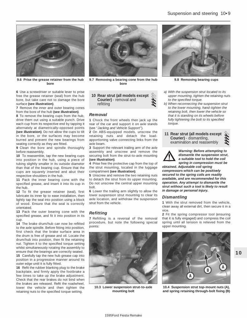
6 Use a screwdriver or suitable lever to prisefree the grease retainer (seal) from the hubbore, but take care not to damage the boresurface (see illustration).7 Remove the inner and outer bearing conesfrom the bore of the hub (see illustration).8 To remove the bearing cups from the hub,drive them out using a suitable punch. Driveeach cup from its respective end by tapping italternately at diametrically-opposed points(see illustration). Do not allow the cups to tiltin the bore, or the surfaces may becomeburred and prevent the new bearings fromseating correctly as they are fitted.9 Clean the bore and spindle thoroughlybefore reassembly.10 To reassemble, tap the new bearing cupsinto position in the hub, using a piece oftubing slightly smaller in its outside diameterthan that of the bearing cup. Ensure that thecups are squarely inserted and abut theirrespective shoulders in the hub.11 Pack the inner bearing cone with thespecified grease, and insert it into its cup inthe hub.12 To fit the grease retainer (seal), firstlubricate its inner lip to ease installation, thenlightly tap the seal into position using a blockof wood. Ensure that the seal is correctlyorientated.13 Pack the outer bearing cone with thespecified grease, and fit it into position in itscup.14 The brake drum/hub can now be refittedto the axle spindle. Before fitting into position,first check that the brake surface area in the drum is free of grease and oil. Locate thedrum/hub into position, then fit the retainingnut. Tighten it to the specified torque settingwhilst simultaneously rotating the assembly toensure that the bearings are correctly seated.15 Carefully tap the new hub grease cap intoposition in a progressive manner around itsouter edge until it is fully fitted.16 Refit the rubber blanking plug to the brakebackplate, and firmly apply the footbrake afew times to take up the brake adjustment.Check that the rear brakes do not bind whenthe brakes are released. Refit the roadwheel,lower the vehicle and then tighten theretaining nuts to the specified torque setting.
10 Rear strut (all models exceptCourier) - removal andrefitting
3Removal1 Chock the front wheels then jack up therear of the car and support it on axle stands(see “Jacking and Vehicle Support”).2 On ABS-equipped models, unscrew theretaining nuts and detach the load-apportioning valve connecting links from theaxle beam.3 Support the relevant trailing arm of the axleassembly and unscrew and remove thesecuring bolt from the strut-to-axle mounting(see illustration).4 Prise free the protective cap from the top ofthe strut mounting, located in the luggagecompartment (see illustration).5 Unscrew and remove the two retaining nutsto detach the strut from its upper mounting.Do not unscrew the central upper mountingbolt.6 Lower the trailing arm slightly to allow thelower suspension strut mounting to clear itsaxle location, and withdraw the suspensionstrut from the vehicle.
Refitting7 Refitting is a reversal of the removalprocedure, but note the following specialpoints:
a) With the suspension strut located to itsupper mounting, tighten the retaining nutsto the specified torque.
b) When reconnecting the suspension strutto the lower mounting, hand-tighten theretaining bolt, then lower the vehicle sothat it is standing on its wheels beforefully tightening the bolt to its specifiedtorque.
11 Rear strut (all models exceptCourier) - dismantling,examination and reassembly
4Warning: Before attempting todismantle the suspension strut,a suitable tool to hold the coilspring in compression must be
obtained. Adjustable coil springcompressors which can be positivelysecured to the spring coils are readilyavailable, and are recommended for thisoperation. Any attempt to dismantle thestrut without such a tool is likely to resultin damage or personal injury.
Dismantling1 With the strut removed from the vehicle,clean away all external dirt, then secure it in avice.2 Fit the spring compressor tool (ensuringthat it is fully engaged) and compress the coilspring until all tension is relieved from theupper mounting.
Suspension and steering 10•9
9.8 Removing bearing cups9.7 Removing a bearing cone from the hubbore
9.6 Prise the grease retainer from the hubbore
10.4 Suspension strut top-mount nuts (A),and spring retaining through-bolt fixing (B)
10.3 Lower suspension strut-to-axlemounting bolt
10
1595Ford Fiesta Remake

3 Unscrew and remove the upper mountingthrough-bolt and nut.4 Withdraw the upper mounting cup and thespring seat.5 The suspension strut and coil spring can nowbe separated. If the coil spring or strut is to berenewed, the original coil spring must bereleased from the compressor. If it is to be re-used, the coil spring can be left in compression.
Examination6 With the strut assembly now completelydismantled, examine the mountingcomponents for wear, damage or deformation.Renew any of the components as necessary.7 Examine the strut for signs of fluid leakage.Check the strut piston for signs of pittingalong its entire length, and check the strutbody for signs of damage or deterioration ofthe mountings. Test the operation of the strut,holding it in an upright position, by moving thepiston through a full stroke, and then throughshort strokes of 50 to 100 mm. In both cases,the resistance felt should be smooth andcontinuous. If the resistance is jerky, oruneven, or if there is any visible sign of wearor damage to the strut, renewal is necessary.
Reassembly8 Reassembly is a reversal of the dismantlingprocedure but note the following points:a) When the spring is located over the
suspension strut, the spring seat, cup andthrough-bolt fitted, tighten the retainingbolt to the specified torque.
b) When reassembled, check that the upperand lower spring tails are correctlyengaged with their spring seats beforeremoving the spring compressor.
12 Rear axle (all models exceptCourier) - removal and refitting
3Removal1 Chock the front wheels then jack up therear of the car and support it on axle stands(see “Jacking and Vehicle Support”). Removethe rear roadwheels.2 Refer to Chapter 9 for details, and disconnectthe handbrake cable equaliser from the primarycable. Remove the handbrake rear cable fromits adjuster and its fixed body locations.3 Disconnect the rear brake flexible hydraulicbrake hoses from their rigid line connections.Clamp the hoses before disconnecting them,to minimise the fluid loss and air entry into thehydraulic system (see Chapter 9 for details).4 On ABS-equipped models, undo theretaining nuts and detach the ABS load-apportioning valve operating links from theaxle beam. Do not remove the load-apportioning valve (see Chapter 9).5 Locate suitable jacks or axle stands underthe axle beam to support its weight (not to liftit), then unscrew the four mounting bracketbolts each side.
6 Unscrew and remove the strut-to-axlemounting bolt each side.7 Check that all associated fittings are clear,then lower the axle and remove it from underthe vehicle.8 If the twist beam axle has been damaged, itmust be renewed. Refer to Chapter 9 fordetails on removing the rear brakes from theaxle. To remove the front mounting/pivotbrackets from the axle, unscrew the pivot bolt.
Refitting9 Refitting is a reversal of the removalprocedure, but note the following:a) Reconnect the axle at the front floor
mountings first, and tighten the retainingbolts to the specified torque.
b) Reconnect the axle to the suspensionstruts, but do not fully retighten the securingbolts until after the vehicle is lowered to theground and is standing on its wheels.
c) Ensure that all brake fluid line connectionsare clean before reconnecting them. Referto the appropriate Sections in Chapter 9for specific details on reconnecting thebrake lines, bleeding the brake hydraulicsystem, and for reconnecting thehandbrake cable and its adjustment.
d) When the vehicle is lowered and is standingon its wheels, tighten the suspensionfastenings to their specified torque settings.
13 Rear axle pivot bushes (allmodels except Courier) -renewal
3Note: Two different types of pivot busheshave been fitted during the course of Fiestaproduction. It is understood that once stocksof the early type are exhausted, only the lattertype will be supplied by Ford parts dealers. Ifrenewing pivot bushes on a pre-April 1990model, and only the later type bushes areavailable, fit the new bushes as describedfrom paragraph 15 onward.
Pre-April 1990 models1 Chock the front wheels then jack up therear of the car and support it on axle stands(see “Jacking and Vehicle Support”).
2 Position a suitable support (preferablyadjustable) under the axle twist beam so thatit is capable of carrying the weight of the axle(not the weight of the vehicle).3 On ABS-equipped models, undo theretaining nuts and detach the ABS load-apportioning valve operating links from theaxle beam. Do not remove the load-apportioning valve (see Chapter 9).4 Unscrew the nuts, withdraw the pivot bolts,then lower the rear axle so that the bushes areclear of their mounting brackets (seeillustration). Take care not to allow the brakepipes to become distorted and stretched - ifnecessary, disconnect the hydraulic lines (seeChapter 9 for details).5 Undo the four body mounting bracket boltsand remove the brackets.6 Using a soft-faced hammer and a suitablepunch or drift, drive the bushes from theirlocations, taking care not to raise any burrs onthe trailing arm eyes.7 To fit the new bushes, obtain a steel tube ofa diameter slightly less than that of the bushlocation in the axle, various flat washers and along bolt and nut.8 Place the new bush in position in its axlelocation with the bush collar nearest to theouter edge of the vehicle. The bush must beinstalled with its voids positioned as shown(see illustration). Using the steel tube,washers, long bolt and nut, draw the bushinwards towards the centre of the vehicle (seeillustration). Care should be taken to avoiddamage to the bush and to obtain correct
10•10 Suspension and steering
13.8b Fitting pivot bush with its collar(arrowed) towards the outer edge of the
vehicle
13.8a Correct pivot bush positioning intrailing arm
A Left-hand side B Right-hand side
13.4 Pivot bush bolt (A) and bodymounting bracket bolts (B)
1595Ford Fiesta Remake

positioning of the voids. Install the bush onthe other side in the same way.9 With the new bushes in position, refit thebody mounting brackets loosely to the trailingarms - do not fully tighten the pivot bolts atthis stage. Final tightening is carried out withthe vehicle standing on its roadwheels.10 Raise the axle assembly so that theconical locating pegs on the body mountingbrackets engage in their body locations. Refitthe body mounting bracket bolts and tightento the specified torque.11 On ABS equipped models, reconnect theload-apportioning valve operating links to therear axle beam12 If the flexible brake hoses weredisconnected during this operation, reconnectthem and bleed the brake hydraulic system(see Chapter 9).13 Lower the vehicle to the ground.14 Fully tighten the bush pivot bolt nuts tothe specified torque.
April 1990 models onward15 As mentioned in the note at the start ofthis Section, all later models are fitted withrevised bushes which use 12 mm (thread size)pivot bolts. If the later type bushes are to befitted to a pre-April 1990 model, twocorresponding bolts and nuts must beobtained at the same time, and either thebody mounting brackets must be replaced bythe corresponding modified items, or theholes in the original brackets must be openedout (to 12.5 mm) to suit the new bolts.16 Carry out the operations described inparagraphs 1 to 4 above.17 Using a steel tube of suitable diameter,various flat washers and a long bolt and nut,draw the bush out of its location in the axletrailing arm.18 Clean the bush eye in the trailing arm;lubricate it, and the new bush, with a soapysolution (washing-up liquid, for example) priorto installation.19 Locate the new bush in position, togetherwith the steel tube, washers, bolt and nut asused for removal. Ensure that the bush flangeis positioned on the outside, then draw thebush fully into position so that its lip isengaged (see illustration).20 Raise the axle to reposition the bush pin
bores in line with the bolt holes in themounting brackets, then insert the pivot bolts.Screw the retaining nuts into position on thepivot bolts, but do not fully tighten them atthis stage.21 Carry out the operations described inparagraphs 11 to 14 above.
14 Rear suspension anti-roll bar(all models except Courier) -removal and refitting
2Removal1 Chock the front wheels then jack up therear of the car and support it on axle stands(see “Jacking and Vehicle Support”).2 Undo the front clamp bolt from each end ofthe bar, then support the bar and undo therear bolt at each end; withdraw the bar (seeillustration).3 Prise open the clamps to release the rubberbushes, if required. Fit the new bushes usingsoapy water as a lubricant.
Refitting4 On refitting, offer up the bar and align firstthe front clamp on each side, refitting thebolts loosely.5 Align and refit the rear clamp on each side;again, tighten the bolts only loosely.
6 Lower the vehicle to the ground, rock it tosettle the suspension, then tighten the clampbolts to the specified torque settings.
15 Rear suspensioncomponents (Couriermodels) - general
Although it is possible to remove the rearsuspension torsion bars and stabiliser barindependently of the complete rear axleassembly, it is essential to have certainspecial tools available to complete the worksuccessfully.
Due to the complexity of the tasks, and therequirement for special tools to accurately setthe suspension geometry and vehicle rideheight on refitting, the removal and refitting ofindividual rear suspension components isconsidered to be beyond the scope of DIYwork and should be entrusted to a Forddealer.
Procedures for removal and refitting of therear shock absorbers, and the complete rearsuspension assembly are given in Sections 16and 17 respectively.
16 Rear shock absorber(Courier models) - removal,examination and refitting
1Removal1 Chock the front wheels then jack up therear of the car and support it on axle stands(see “Jacking and Vehicle Support”).2 Support the relevant trailing arm of thesuspension assembly and unscrew the uppermounting bolt and nut, followed by the lowerbolt. Withdraw the shock absorber from underthe vehicle (see illustrations).
Examination3 Examine the shock absorber body for signsof fluid leakage or damage and check the
Suspension and steering 10•11
14.2 Rear suspension anti-roll bar
1 Rear suspension strut2 Anti-roll bar3 Inset showing (front) mounting clamp
13.19 Pivot bush renewal (April 1990models onwards) - correct engagement of
bush lip on rear axle
A New bush, installed correctlyB New bush, installed incorrectly
16.2b . . . and lower mounting on Couriermodels
16.2a Removing a shock absorber uppermounting . . .
10
1595Ford Fiesta Remake

mountings for signs of wear. Test theoperation of the unit, holding it in an uprightposition, by moving the piston through a fullstroke, and then through short strokes of 50to 100 mm. In both cases, the resistance feltshould be smooth and continuous. If theresistance is jerky, or uneven, or if there is anyvisible sign of wear or damage, the shockabsorber should be renewed. Note that ifeither unit is to be renewed, it is good practiceto renew both together as a matched pair.
Refitting4 Locate the unit in position and refit themounting bolts and nut. Do not fully tightenthe mountings at this stage.5 Lower the vehicle to the ground and rock itto settle the suspension. Raise the vehicleagain, as necessary, until the shock absorberis at an angle of 50° ± 5° to the horizontal.With the shock absorber in this position,tighten the upper and lower mountings to thespecified torque.
17 Rear suspension assembly(Courier models) - removal and refitting
3Removal1 Chock the front wheels then jack up therear of the car and support it on axle stands(see “Jacking and Vehicle Support”). Removethe rear roadwheels.2 Refer to Chapter 9 for details, anddisconnect the handbrake cable equaliserfrom the primary cable. Remove thehandbrake rear cable from its adjuster and itsfixed body locations. Release the exhaustsystem mountings as necessary to allow thehandbrake cable to be withdrawn over therear of the exhaust.3 Disconnect the rear brake flexible hydraulicbrake hoses from their rigid line connections(see illustration). Clamp the hoses beforedisconnecting them, to minimise the fluid lossand air entry into the hydraulic system (seeChapter 9 for details).4 Detach the light-laden valve linkage fromthe bracket on the suspension assembly.
5 Locate suitable jacks under the suspensionassembly to support its weight (not to lift it).6 Unscrew the shock absorber lowermounting bolts on each side.7 Unscrew the two mounting bracket boltseach side (see illustration), check that allassociated fittings are clear, then lower thesuspension assembly and remove it fromunder the vehicle.
Refitting8 Refitting is a reversal of the removalprocedure, but note the following:a) Refit the front mounting brackets first,
and tighten the retaining bolts to thespecified torque.
b) Reconnect the shock absorber lowermountings, but do not fully retighten thesecuring bolts until after the vehicle islowered to the ground and is standing onits wheels.
c) Ensure that all brake fluid line connectionsare clean before reconnecting them. Referto the appropriate Sections in Chapter 9for specific details on reconnecting thebrake lines, bleeding the brake hydraulicsystem, adjusting the light laden valve,and reconnecting and adjusting thehandbrake cable.
d) Once the vehicle is standing on itswheels, raise it again, as necessary, untilthe shock absorbers are at an angle of50° ± 5° to the horizontal. With the shockabsorbers in this position, tighten thelower mountings to the specified torque.
18 Rear suspension ride height(Courier models) - adjustment 4
Checking of the ride height requires the useof Ford special tools to accurately compressthe suspension to a pre-determined value.Further special tools are then required toreposition the torsion bars to the new setting.
This operation should be entrusted to aFord dealer, as it is not possible to carry outthe procedure accurately without the use of the appropriate tools.
19 Steering wheel - removal and refitting 2
Removal
Models without air bag1 Drive the vehicle in a straight line onto alevel surface, so that the roadwheels arepointing straight ahead.2 Carefully prise the motif from the centre ofthe steering wheel (see illustration).3 Mark the relative positions of the steeringwheel and steering column shaft.4 Unscrew the retaining bolt from the centreof the steering wheel, then insert the ignitionkey and turn it to position “I”. Grip the wheeleach side, then pull and withdraw it from thecolumn shaft.
Models with air bagWarning: Handle the air bag withextreme care as a precautionagainst personal injury, andalways hold it with the cover
facing away from your body. If in doubtconcerning any proposed work involvingthe air bag or its control circuitry, consult aFord dealer or other qualified specialist.5 Disconnect the battery negative (earth) lead(refer to Chapter 5A, Section 1).
Warning: Before proceeding,wait a minimum of 15 minutes,as a precaution againstaccidental firing of the air bag.
This period ensures that any stored energyin the back-up capacitor is dissipated.6 Undo the screws, and remove the steeringcolumn lower shroud.7 Undo the two external screws and the twointernal screws and remove the steeringcolumn upper shroud.
10•12 Suspension and steering
19.2 Removing the motif from the steeringwheel
17.7 Courier rear suspension pivotbrackets locate on dowels in underbody
17.3 Brake hose and rigid pipe connectionon Courier rear suspension assembly
1595Ford Fiesta Remake
If the wheel is tight, tap it upnear the centre, using thepalm of your hand, or twist itfrom side to side, whilst
pulling upwards to release it from theshaft splines.

8 Turn the steering wheel as necessary sothat one of the air bag module retaining boltsbecomes accessible from the rear of thesteering wheel. Undo the bolt, then turn the steering wheel again until the second boltis accessible. Undo this bolt also.9 Withdraw the air bag module from thesteering wheel far enough to access thewiring multi-plug. Some force may be neededto free the module from the additional steeringwheel spoke retainers.10 Disconnect the multi-plug from the rear ofthe module, and remove the module from thevehicle.
Warning: Position the air bagmodule in a safe place, with themechanism facing downwardsas a precaution againstaccidental operation.
11 Release the wiring harness from the sideof the steering column and disconnect the airbag module wiring multi-plug (yellow lead).12 Where applicable, undo the single screwand withdraw the Passive Anti-Theft System(PATS) transceiver from the ignitionswitch/steering lock barrel (see illustration).13 Turn the steering wheel so that theroadwheels are in the straight-ahead position,then remove the ignition key to lock thesteering.14 Unscrew the retaining bolt from the centreof the steering wheel, then insert the ignition
key and turn it to position “I”. Grip the steeringwheel each side, then pull and withdraw itfrom the column shaft.
Refitting
All models15 Refit in the reverse order of removal.Make sure that the wheel is centralised, asnoted on removal and turn the ignition key sothat it is in position “I” (steering unlocked).Tighten the retaining bolt to the specifiedtorque setting.
20 Steering column (manualsteering) - removal and refitting
3Removal
Models without air bag1 Disconnect the battery negative (earth) lead(refer to Chapter 5A, Section 1).2 Remove the manual choke control knob,where fitted, by depressing the lug securing it,and pulling it from its shaft (see illustration).The lug is found on the side of the controlknob shank.3 Remove the lower steering column shroudby undoing its four retaining screws, thendetach the choke warning light switch/pullcontrol assembly from the lower shroud byunscrewing its retaining collar (bayonet-type
fixing), using a suitable tool to locate in thecollar recesses (see illustration).4 Remove the two screws securing the uppersteering column shroud from above, and thetwo screws securing it from below, the latteraccessible only with the lower shroudremoved.5 Disconnect the wiring multi-plugs from thesteering column multi-function switchassembly, then remove the single screwsecuring the multi-function switch assemblyto the steering column lock housing. Thisretaining screw is located directly forward ofthe hazard warning light switch (seeillustration). Remove the multi-functionswitch assembly.6 Disconnect the ignition switch wiring multi-plug connector and remove the loom platefrom its location on the left-hand side of thesteering column (see illustration).7 Unclip the bonnet release cable abutmentfrom its location in the steering column lockhousing, then detach the cable from thebonnet release lever by aligning the cablecore with the slot on the release lever andwithdrawing it through that slot. Detach thespring from the release lever arms, thendisengage the arms from the steering columnlock housing and remove the bonnet releaselever (see illustration).
Suspension and steering 10•13
20.3 Removing the manual choke controlassembly retaining collar
20.2 Manual choke control knob and itslocating lug (arrowed)
19.12 Undo the screw (arrowed) andwithdraw the Passive Anti-Theft System
(PATS) transceiver from the ignitionswitch/steering lock barrel
20.7 Bonnet release lever and cable
A Bonnet release cable abutmentB Bonnet release cable slot on release leverC Bonnet release lever return springD Steering column to mounting bracket
retaining nuts
20.6 Removing ignition loom plate fromsteering column lock housing (steering
wheel removed for clarity)
20.5 Steering column multi-functionswitch retaining screw (arrowed) (steering
wheel removed for clarity)
10
1595Ford Fiesta Remake
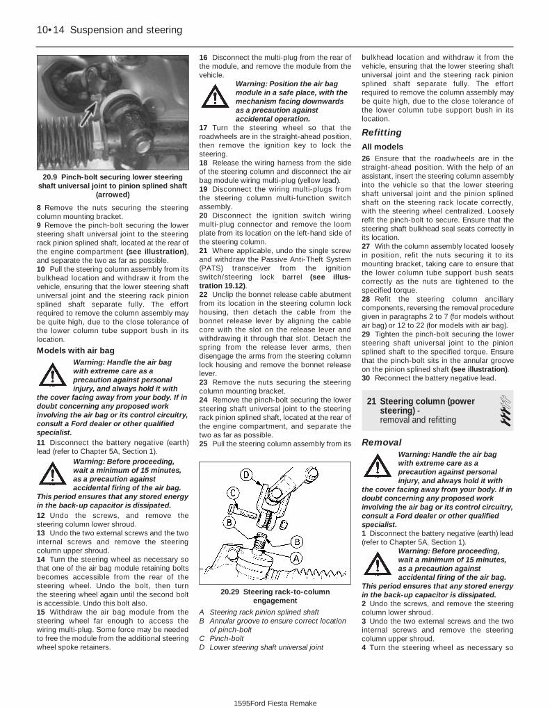
8 Remove the nuts securing the steeringcolumn mounting bracket.9 Remove the pinch-bolt securing the lowersteering shaft universal joint to the steeringrack pinion splined shaft, located at the rear ofthe engine compartment (see illustration),and separate the two as far as possible.10 Pull the steering column assembly from itsbulkhead location and withdraw it from thevehicle, ensuring that the lower steering shaftuniversal joint and the steering rack pinionsplined shaft separate fully. The effortrequired to remove the column assembly maybe quite high, due to the close tolerance ofthe lower column tube support bush in itslocation.
Models with air bagWarning: Handle the air bagwith extreme care as aprecaution against personalinjury, and always hold it with
the cover facing away from your body. If indoubt concerning any proposed workinvolving the air bag or its control circuitry,consult a Ford dealer or other qualifiedspecialist.11 Disconnect the battery negative (earth)lead (refer to Chapter 5A, Section 1).
Warning: Before proceeding,wait a minimum of 15 minutes,as a precaution againstaccidental firing of the air bag.
This period ensures that any stored energyin the back-up capacitor is dissipated.12 Undo the screws, and remove thesteering column lower shroud.13 Undo the two external screws and the twointernal screws and remove the steeringcolumn upper shroud.14 Turn the steering wheel as necessary sothat one of the air bag module retaining boltsbecomes accessible from the rear of thesteering wheel. Undo the bolt, then turn the steering wheel again until the second boltis accessible. Undo this bolt also.15 Withdraw the air bag module from thesteering wheel far enough to access thewiring multi-plug. Some force may be neededto free the module from the additional steeringwheel spoke retainers.
16 Disconnect the multi-plug from the rear ofthe module, and remove the module from thevehicle.
Warning: Position the air bagmodule in a safe place, with themechanism facing downwardsas a precaution againstaccidental operation.
17 Turn the steering wheel so that theroadwheels are in the straight-ahead position,then remove the ignition key to lock thesteering.18 Release the wiring harness from the sideof the steering column and disconnect the airbag module wiring multi-plug (yellow lead).19 Disconnect the wiring multi-plugs fromthe steering column multi-function switchassembly.20 Disconnect the ignition switch wiringmulti-plug connector and remove the loomplate from its location on the left-hand side ofthe steering column.21 Where applicable, undo the single screwand withdraw the Passive Anti-Theft System(PATS) transceiver from the ignitionswitch/steering lock barrel (see illus-tration 19.12).22 Unclip the bonnet release cable abutmentfrom its location in the steering column lockhousing, then detach the cable from thebonnet release lever by aligning the cablecore with the slot on the release lever andwithdrawing it through that slot. Detach thespring from the release lever arms, thendisengage the arms from the steering columnlock housing and remove the bonnet releaselever.23 Remove the nuts securing the steeringcolumn mounting bracket.24 Remove the pinch-bolt securing the lowersteering shaft universal joint to the steeringrack pinion splined shaft, located at the rear ofthe engine compartment, and separate thetwo as far as possible.25 Pull the steering column assembly from its
bulkhead location and withdraw it from thevehicle, ensuring that the lower steering shaftuniversal joint and the steering rack pinionsplined shaft separate fully. The effortrequired to remove the column assembly maybe quite high, due to the close tolerance ofthe lower column tube support bush in itslocation.
Refitting
All models26 Ensure that the roadwheels are in thestraight-ahead position. With the help of anassistant, insert the steering column assemblyinto the vehicle so that the lower steeringshaft universal joint and the pinion splinedshaft on the steering rack locate correctly,with the steering wheel centralized. Looselyrefit the pinch-bolt to secure. Ensure that thesteering shaft bulkhead seal seats correctly inits location.27 With the column assembly located looselyin position, refit the nuts securing it to itsmounting bracket, taking care to ensure thatthe lower column tube support bush seatscorrectly as the nuts are tightened to thespecified torque.28 Refit the steering column ancillarycomponents, reversing the removal proceduregiven in paragraphs 2 to 7 (for models withoutair bag) or 12 to 22 (for models with air bag).29 Tighten the pinch-bolt securing the lowersteering shaft universal joint to the pinionsplined shaft to the specified torque. Ensurethat the pinch-bolt sits in the annular grooveon the pinion splined shaft (see illustration).30 Reconnect the battery negative lead.
21 Steering column (powersteering) - removal and refitting
3Removal
Warning: Handle the air bagwith extreme care as aprecaution against personalinjury, and always hold it with
the cover facing away from your body. If indoubt concerning any proposed workinvolving the air bag or its control circuitry,consult a Ford dealer or other qualifiedspecialist.1 Disconnect the battery negative (earth) lead(refer to Chapter 5A, Section 1).
Warning: Before proceeding,wait a minimum of 15 minutes,as a precaution againstaccidental firing of the air bag.
This period ensures that any stored energyin the back-up capacitor is dissipated.2 Undo the screws, and remove the steeringcolumn lower shroud.3 Undo the two external screws and the twointernal screws and remove the steeringcolumn upper shroud.4 Turn the steering wheel as necessary so
10•14 Suspension and steering
20.29 Steering rack-to-columnengagement
A Steering rack pinion splined shaftB Annular groove to ensure correct location
of pinch-boltC Pinch-boltD Lower steering shaft universal joint
20.9 Pinch-bolt securing lower steeringshaft universal joint to pinion splined shaft
(arrowed)
1595Ford Fiesta Remake

that one of the air bag module retaining boltsbecomes accessible from the rear of thesteering wheel. Undo the bolt, then turn the steering wheel again until the second boltis accessible. Undo this bolt also.5 Withdraw the air bag module from thesteering wheel far enough to access thewiring multi-plug. Some force may be neededto free the module from the additional steeringwheel spoke retainers.6 Disconnect the multi-plug from the rear ofthe module, and remove the module from thevehicle.
Warning: Position the air bagmodule in a safe place, with themechanism facing downwardsas a precaution againstaccidental operation.
7 Turn the steering wheel so that theroadwheels are in the straight-ahead position,then remove the ignition key to lock thesteering.8 Release the wiring harness from the side ofthe steering column and disconnect the airbag module wiring multi-plug (yellow lead).9 Disconnect the wiring multi-plugs from thesteering column multi-function switchassembly.10 Disconnect the ignition switch wiringmulti-plug connector and remove the loomplate from its location on the left-hand side ofthe steering column.11 Undo the single screw and withdraw thePassive Anti-Theft System (PATS) transceiverfrom the ignition switch/steering lock barrel(see illustration 19.12).12 Unclip the bonnet release cable abutmentfrom its location in the steering column lockhousing, then detach the cable from thebonnet release lever by aligning the cablecore with the slot on the release lever andwithdrawing it through that slot. Detach thespring from the release lever arms, thendisengage the arms from the steering columnlock housing and remove the bonnet releaselever.13 Remove the C-clip at the base of thesteering column shaft, below the universaljoint.14 Remove the nuts securing the steeringcolumn mounting bracket.15 Pull the steering column assembly from itsbulkhead location and withdraw it from thevehicle, ensuring that the steering columnshaft and flexible coupling separate fully.
Refitting16 Ensure that the roadwheels are in thestraight-ahead position and the steeringcolumn is locked. With the help of anassistant, insert the steering column assemblyinto the vehicle so that the steering columnshaft engages with the flexible coupling.17 Refit the steering column shaft C-clip.18 With the column assembly located looselyin position, refit and tighten the nuts securingit to its mounting bracket.19 Refit the steering column ancillary
components, reversing the removal proceduregiven in paragraphs 2 to 12.20 Reconnect the battery negative lead.
22 Steering gear rubber gaiters- renewal 3
1 Remove the track rod end balljoint asdescribed in Section 28.2 Remove the one-piece undertray wherefitted, by turning its bayonet-type fasteners,and on XR2i models, remove the frontsuspension crossmember as described inSection 7.3 Count the number of exposed threadsvisible, from the end of the track rod to thetrack rod end balljoint locknut, and record thisfigure. Now unscrew the locknut from thetrack rod.4 Release the clip(s), and slide the gaiter offthe rack-and-pinion housing and track rod.5 Scrape off all grease from the old gaiter,and apply to the track rod inner joint. Wipeclean the seating areas on the rack-and-pinion housing and track rod.6 Slide the new gaiter onto the housing andtrack rod, and secure with the retaining clips.Ensure that the narrow neck locates correctlyin the track rod groove.7 Screw the track rod end balljoint locknutback onto the track rod until the same numberof threads, as counted on removal, are visible.8 Refit the track rod end balljoint asdescribed in Section 28.9 Refit the front suspension crossmemberand one-piece undertray, as applicable.
23 Steering gear (manual steering) - removal and refitting
3Removal1 Disconnect the battery negative (earth) lead(refer to Chapter 5A, Section 1).2 Chock the rear wheels then jack up thefront of the car and support it on axle stands(see “Jacking and Vehicle Support”). Removethe front roadwheels.3 Remove the one-piece undertray wherefitted, by turning its bayonet-type fasteners,and on XR2i models, remove the frontsuspension crossmember as described inSection 7.4 Remove the pinch-bolt securing the pinionsplined shaft to the lower steering shaftuniversal joints, located at the rear of theengine compartment.5 Separate the track rod end balljoints fromthe steering arms, as described in Section 28.6 Remove the lower brake servo supportbracket bolt.7 Remove the other bolt securing the steeringrack assembly to the bulkhead, then withdrawit from the right-hand side of the vehicle,
taking care to disengage the pinion splinedshaft from the lower steering shaft universaljoint as the assembly is moved.
Refitting8 Centralize the rack and steering wheel, thenengage the pinion splined shaft to the lowersteering shaft universal joint.9 Refit the steering rack assembly mountingbolts to the bulkhead and tighten to thespecified torque, ensuring that the servosupport bracket is correctly held.10 Refit the pinion splined shaft-to-lowersteering shaft universal joint pinch-bolt andnut and tighten to the specified torque,ensuring that the pinch-bolt locates to theannular groove as the pinion splined shaft.11 Refit the track rod end balljoints to thesteering arms, as detailed in Section 28. Aslong as the track rod end-to-track rod relativepositions have not been disturbed, it will notbe necessary to reset the front wheelalignment.12 Refit the front suspension crossmemberand one-piece undertray, as applicable.13 Refit the roadwheels, then lower thevehicle to the ground. Tighten the roadwheelnuts to the specified torque with the vehicleon its wheels.
24 Steering gear (power steering) - removal and refitting
4Removal1 Disconnect the battery negative (earth) lead(refer to Chapter 5A, Section 1).2 Chock the rear wheels then jack up thefront of the car and support it on axle stands(see “Jacking and Vehicle Support”). Removethe front roadwheels.3 Remove the one-piece undertray wherefitted, by turning its bayonet-type fasteners,and on XR2i models, remove the frontsuspension crossmember as described inSection 7.4 Remove the pinch-bolt securing the pinionsplined shaft to the lower steering shaftflexible coupling, located at the rear of theengine compartment.5 Undo the retaining screws, and detach theclips securing the power steering hydraulicpressure pipes to the steering gear.6 Position a suitable container under thehydraulic pipe connections to the steeringgear. Unscrew the pipe unions, then detachthe pipes from the valve body. Withdraw thepipes from the steering gear, and drain thehydraulic fluid into the container.7 Plug the exposed ends of the hydraulic lineconnections, to prevent the ingress of dirt andfurther fluid loss. Note that new O-ring sealswill be needed for the pressure and returnhose connections when reconnecting.8 Slacken the upper bolts securing thesteering gear support brackets. On left-hand
Suspension and steering 10•15
10
1595Ford Fiesta Remake

drive models, remove the brace from the studon the left-hand side of the steering gear.9 Undo the two bolts securing the supportbrackets to the steering gear and move thebrackets and swing the brackets clear.10 Unhook the steering gear from theapertures in the bulkhead and remove theassembly from the right-hand wheel arch.Ensure that the pressure check valve does notfall out of the pressure port in the valve bodyas the steering gear is removed.
Refitting11 Centralize the steering gear and steeringwheel, then engage the pinion splined shaft tothe lower steering shaft flexible coupling.12 Hook the steering gear into the aperturesin the bulkhead then align the supportbrackets and refit the two bolts. Tighten thesupport bracket upper bolts and supportbracket-to-steering gear bolts to the specifiedtorque.13 On left-hand drive models, refit the braceto the stud on the left-hand side of thesteering gear.14 Fit new O-ring seals to the pressure andreturn hoses, then reconnect the hydrauliclines to the steering gear. Secure the pipeswith the retaining clips.15 Refit the pinion splined shaft-to-lowersteering shaft flexible coupling pinch-bolt andnut and tighten to the specified torque.16 Refit the track rod end balljoints to thesteering arms, as detailed in Section 28. Aslong as the track rod end-to-track rod relativepositions have not been disturbed, it will notbe necessary to reset the front wheelalignment.17 Refit the front suspension crossmemberand one-piece undertray, as applicable.18 Refit the roadwheels, then lower thevehicle to the ground. Tighten the roadwheelnuts with the vehicle on its wheels to thespecified torque.19 On completion, bleed the power steeringhydraulic system as described in Section 27.Check for any signs of fluid leakage from thesystem hoses and connections.
25 Power steering pump -removal and refitting 4
Removal
HCS engine models1 Disconnect the battery negative (earth) lead(refer to Chapter 5A, Section 1).2 Chock the rear wheels then jack up thefront of the car and support it on axle stands(see “Jacking and Vehicle Support”). Removethe front roadwheel.3 Remove the auxiliary drivebelt as describedin Chapter 1.4 Insert a 9 mm Allen key into the centre ofthe pump drive spindle to prevent it from
turning, then unscrew and remove the threepump pulley retaining bolts. Withdraw thepulley from the pump.5 Position a suitable container beneath thepower steering pump, then unscrew and detachthe fluid high pressure pipe and fluid returnhose from the pump. As they are detached fromthe pump, allow the fluid to drain from the pipeand hose (and the pump) into the container.Plug the exposed ends of the pipe, hose andthe pump connections, to prevent the ingress ofdirt and excessive fluid loss.6 Unscrew the four retaining bolts (three fromthe front and one from the rear) and withdrawthe pump from the vehicle.
PTE engine models7 Disconnect the battery negative (earth) lead(refer to Chapter 5A, Section 1).8 Refer to the relevant Part of Chapter 4 andremove the air cleaner assembly and air inletcomponents as necessary for access to thepump.9 Chock the rear wheels then jack up thefront of the car and support it on axle stands(see “Jacking and Vehicle Support”). Removethe front roadwheel.10 Refer to Chapter 1 and drain the coolingsystem.11 Refer to Chapter 1 and remove theauxiliary drivebelt.12 Insert a 9 mm Allen key into the centre ofthe pump drive spindle to prevent it fromturning, then unscrew and remove the threepump pulley retaining bolts. Refit theroadwheel, lower the vehicle and withdraw thepump pulley from above.13 Disconnect the cooling system hoses asnecessary to gain access to the powersteering pump.14 Disconnect the pressure switch multi-plugfrom the pressure switch located in the fluidhigh pressure pipe.15 Position a suitable container beneath thepower steering pump, then disconnect thehigh pressure pipe at the union located partway along the pipe. Allow the fluid to drainfrom the pipe into the container.16 Disconnect the high pressure pipe clampbracket and the fluid return hose from thepump. Allow the fluid to drain into thecontainer then plug the exposed ends of thepipe, hose and the pump connections, toprevent the ingress of dirt and excessive fluidloss.17 Unscrew the pump mounting bolt locatedat the rear of the pump and remove the pipeclamp bracket.18 Unscrew the three pump mounting boltslocated at the front of the pump and removethe pump, complete with high pressure pipe,from the vehicle.19 If required, the high pressure pipe can beremoved from the pump after unscrewing theunion nut.
Zetec engine modelsNote: For this operation, the engine will needto be supported from above to allow removal
of the right-hand engine mounting, and also toallow the vehicle to be raised for workunderneath, and lowered for work from above.A proprietary engine support bar (or home-made alternative) fitted in the front wing drainchannel each side is ideal for this purpose, butcare must be taken not to damage the wingsor their paintwork.20 Disconnect the battery negative (earth)lead (refer to Chapter 5A, Section 1).21 Suitably support the right-hand side of theengine (see the note at the beginning of thissub-Section) so that all the load is removedfrom the engine mounting.22 Remove the right-hand engine mountingas described in Chapter 2C.23 Refer to Chapter 1 and drain the coolingsystem.24 Chock the rear wheels then jack up thefront of the car and support it on axle stands(see “Jacking and Vehicle Support”). Removethe front roadwheel.25 Undo the retaining screws, and removethe drivebelt lower guard from the underbody.26 Refer to Chapter 11 and remove the wheelarch liner.27 Refer to Chapter 1 and remove theauxiliary drivebelt.28 Insert a 9 mm Allen key into the centre ofthe pump drive spindle to prevent it fromturning, then unscrew and remove the threepump pulley retaining bolts. Refit theroadwheel, lower the vehicle and withdraw thepump pulley from above.29 Refer to Chapter 12 and remove the right-hand headlight unit.30 Refit the roadwheel and lower the vehicleto the ground.31 Position a suitable container beneath thepower steering fluid reservoir, then disconnectthe fluid return hose from the reservoir. Allowthe fluid to drain from the hose and reservoirinto the container.32 Plug the exposed ends of the hose andthe reservoir, to prevent the ingress of dirt andexcessive fluid loss.33 Remove the high pressure pipe clampbrackets from the engine then disconnect thehigh pressure pipe at the union located overthe camshaft cover. Place absorbent ragsunder the union as it is disconnected tocollect any escaping fluid. Plug thedisconnected pipe ends to prevent theingress of dirt and excessive fluid loss.34 Disconnect the cooling system hoses asnecessary to gain access to the powersteering pump.35 Unscrew the two pump mounting boltslocated at the rear of the pump.36 Unscrew the two pump mounting boltslocated at the front of the pump and removethe pump, complete with high pressure pipeand fluid return hose, upwards and out of theengine compartment.37 If required, the high pressure pipe andfluid return hose can be removed from thepump after unscrewing the union nut orslackening the hose clip as applicable.
10•16 Suspension and steering
1595Ford Fiesta Remake

Refitting
All models38 Refitting is a reversal of removal, bearingin mind the following points:a) Tighten all nuts and bolts to the specified
torque. Remove the plugs from thedisconnected pipes, hoses and unionsand ensure that the pipes are locatedcorrectly so that they do not foul anysurrounding components.
b) Refit the auxiliary drivebelt as described inChapter 1.
c) Where drained, refill the cooling systemas described in Chapter 1.
d) Refit or reconnect any additionalcomponents removed for access asdescribed in the relevant Sections andChapters of this manual.
e) On completion, bleed the power steeringhydraulic system as described in Section27. Check for any signs of fluid leakagefrom the system hoses and connections.
26 Power steering fluid cooler -removal and refitting 2
Removal1 Disconnect the battery negative (earth) lead(refer to Chapter 5A, Section 1).2 Position a suitable container beneath thepower steering fluid cooler hose connections,then disconnect the hoses at the quick-fitcouplings on the fluid cooler. Allow the fluid todrain from the hose and reservoir into thecontainer.3 Plug the exposed ends of the hose and thereservoir, to prevent the ingress of dirt andexcessive fluid loss.4 Refer to Chapter 11 and remove the bonnetlock assembly and the front bumper.5 Undo the bolts securing the cooler sidesupport bracket and the bonnet lock stay, andremove the fluid cooler and bonnet lock stayas an assembly.6 Undo the two bolts and remove the stayfrom the fluid cooler.
Refitting7 Refitting is a reversal of removal. Oncompletion, bleed the power steeringhydraulic system as described in Section 27.
27 Power steering hydraulicsystem - bleeding 2
1 Following any operation in which the powersteering fluid lines have been disconnected,the power steering system must be bled toremove any trapped air.2 With the front wheel in the straight-aheadposition, check the power steering fluid levelin the reservoir and, if low, top-up with fresh
fluid to the “MAX” or “MAX COLD” level mark.Pour the fluid slowly to prevent air bubblesforming, and use only the specified fluid (referto “Lubricants, fluids and tyre pressures”).3 Start the engine and allow it to idle. Checkthe hoses and connections for leaks.4 Stop the engine and recheck the fluid level.Add more, if necessary, up to the “MAX” or“MAX COLD” level mark.5 Start the engine again, allow it to idle, thenbleed the system by slowly moving thesteering from lock-to-lock several times. Thisshould purge the system of all internal air.However, if air remains in the system(indicated by the steering operation being verynoisy), leave the vehicle overnight and repeatthe procedure again the next day.6 If air still remains in the system, it may benecessary to resort to the Ford method ofbleeding, which uses a vacuum pump and amodified reservoir filler cap to which the pumpcan be connected. Turn the steering to theright until it is near the stop, then fit thevacuum pump to the fluid reservoir, and apply0.51 bars of vacuum. Maintain the vacuum fora minimum of 5 minutes, then repeat the procedure with the steering turned to theleft.7 Keep the fluid level topped-up throughoutthe bleeding procedure; note that the fluidtemperature increases, the level will rise.8 On completion, switch the engine off, andreturn the wheels to the straight-aheadposition.
28 Track rod end balljoint -removal and refitting 2
Removal1 Chock the rear wheels then jack up thefront of the car and support it on axle stands(see “Jacking and Vehicle Support”). Removethe appropriate front roadwheel.2 Using a suitable spanner, slacken the trackrod end balljoint locknut on the track rod by aquarter of a turn only (see illustration). Hold
the balljoint stationary with another spannerengaged with the flats at its inner end toprevent it from turning.3 Extract the split pin, then loosen off theretaining nut. If the balljoint is to be renewed,the nut can be fully removed. If the existingballjoint is to be reconnected, the nut shouldbe slackened off a couple of turns only at first,and left in position to protect the joint threadsas the joint is separated from the spindlecarrier. To release the tapered shank of thejoint from the spindle carrier, use a balljointseparator tool as shown (see illustration). Ifthe joint is to be re-used, take care not todamage the rubber dust cover when using aseparator tool.4 Unscrew the balljoint from the track rod,counting the number of turns necessary toremove it.
Refitting5 Screw the balljoint into the track rod thenumber of turns noted during removal until theballjoint just contacts the locknut. Now tightenthe locknut while holding the balljoint.6 Engage the shank of the balljoint with thespindle carrier arm, and refit the retaining nut.Tighten the nut to the specified torque andsecure with a new split pin.7 Refit the roadwheel, and lower the vehicleto the ground.8 Finally, have the front wheel toe settingchecked (see Section 29).
29 Wheel alignment andsteering angles - generalinformation
4General1 A car’s steering and suspension geometryis defined in four basic settings - all anglesare expressed in degrees (toe settings arealso expressed as a measurement); therelevant settings are camber, castor, steeringaxis inclination, and toe-setting. With theexception of front wheel toe-setting, none ofthese settings are adjustable.
Suspension and steering 10•17
28.3 Balljoint separator tool in position.Note that the nut should be left loosely inposition to protect the thread for re-use
28.2 Track rod end balljoint showing thelocknut (A) retaining flats (B) and the
balljoint-to-spindle carrier arm retainingnut and split pin (C)
10
1595Ford Fiesta Remake

Front wheel toe setting -checking and adjustment2 Due to the special measuring equipmentnecessary to accurately check the wheelalignment, and the skill required to use itproperly, checking and adjustment is best leftto a Ford dealer or similar expert. Note thatmost tyre-fitting shops now possesssophisticated checking equipment. Thefollowing is provided as a guide, should theowner decide to carry out a DIY check.3 The front wheel toe setting is checked bymeasuring the distance between the front andrear inside edges of the roadwheel rims.Proprietary toe measurement gauges areavailable from motor accessory shops.Adjustment is made by screwing the trackrods in or out of their track rod end balljoints,to alter the effective length of the track rodassemblies.4 For accurate checking, the vehicle mustbe at the kerb weight, ie unladen and with afull tank of fuel.5 Before starting work, check the tyrepressures and tread wear, the condition of thehub bearings, the steering wheel free play,and the condition of the front suspensioncomponents (see Chapter 1). Correct anyfaults found.6 Park the vehicle on level ground, check thatthe front roadwheels are in the straight-aheadposition, then rock the rear and front ends to
settle the suspension. Release the handbrake,and roll the vehicle backwards 1 metre, thenforwards again, to relieve any stresses in thesteering and suspension components.7 Measure the distance between the frontedges of the wheel rims and the rear edges ofthe rims. Subtract the smallest measurementfrom the largest, and check that the result iswithin the specified range.8 If adjustment is necessary, apply thehandbrake, then jack up the front of thevehicle and support it securely on axle stands(see “Jacking and Vehicle Support”). Turn thesteering wheel onto full-left lock, and recordthe number of exposed threads on the right-hand track rod. Now turn the steering ontofull-right lock, and record the number ofthreads on the left-hand side. If there are thesame number of threads visible on both sides,then subsequent adjustment should be madeequally on both sides. If there are morethreads visible on one side than the other, itwill be necessary to compensate for thisduring adjustment. Note: It is most importantthat after adjustment, the same number ofthreads are visible on each track rod.9 First clean the track rod end; if they arecorroded, apply penetrating fluid beforestarting adjustment. Release the rubber gaiteroutboard clips (where necessary), and peelback the gaiter; apply a smear of grease tothe inside of the gaiter, so that both are free,
and will not be twisted or strained as theirrespective track rods are rotated.10 Use a straight-edge and a scriber orsimilar to mark the relationship of each trackrod to its track rod end balljoint, then, holdingeach track rod in turn, unscrew its locknutfully.11 Alter the length of the track rods, bearingin mind the note made in paragraph 8. Screwthem into or out of the track rod end balljoints,rotating the track rods using a self-gripwrench. Shortening the track rods (screwingthem into their track rod end balljoints) willreduce toe-in/increase toe-out.12 When the setting is correct, hold the trackrods and securely tighten the track rod endballjoint locknuts. Count the exposed threadsto check the length of both track rods. If theyare not the same, then the adjustment has notbeen made equally, and problems will beencountered with tyre scrubbing in turns;also, the steering wheel spokes will no longerbe horizontal when the wheels are in thestraight-ahead position.13 If the track rod lengths are the same, lowerthe vehicle to the ground and re-check the toe setting; re-adjust if necessary. When thesetting is correct, securely tighten the track rodend balljoint locknuts. Ensure that the rubbergaiters are seated correctly, and are nottwisted or strained, and secure them in positionwith new retaining clips (where necessary).
10•18 Suspension and steering
1595Ford Fiesta Remake

11
1595Ford Fiesta Remake
Torque wrench settings Nm lbf ftFront seat slide mechanism-to-floor mounting bolts . . . . . . . . . . . . . . . 25 to 32 18 to 24Rear seat backrest hinge to backrest . . . . . . . . . . . . . . . . . . . . . . . . . . . 3.7 to 4.6 2.7 to 3.4Rear seat backrest hinge to body . . . . . . . . . . . . . . . . . . . . . . . . . . . . . 21 to 25 15 to 18Rear seat belt anchors and stalks to body . . . . . . . . . . . . . . . . . . . . . . . 25 to 45 18 to 34Rear seat belt retractor assembly to body . . . . . . . . . . . . . . . . . . . . . . . 25 to 45 18 to 34Front seat belt stalks to floorpan . . . . . . . . . . . . . . . . . . . . . . . . . . . . . . 25 to 45 18 to 34Front seat belt lower anchor bolt to body . . . . . . . . . . . . . . . . . . . . . . . 25 to 45 18 to 34Front seat belt lower anchor slide bar bolt to body . . . . . . . . . . . . . . . . 25 to 45 18 to 34Front seat belt retractor to B-pillar bolt . . . . . . . . . . . . . . . . . . . . . . . . . 25 to 45 18 to 34Front seat belt upper anchor bolt to B-pillar (non-adjustable type) . . . . 25 to 45 18 to 34Front seat belt upper anchor adjuster plate-to-B-pillar bolts . . . . . . . . . 19 to 28 14 to 22Front seat belt upper anchor bolt to adjuster slide . . . . . . . . . . . . . . . . 25 to 45 18 to 34Bonnet hinge-to-bonnet bolts . . . . . . . . . . . . . . . . . . . . . . . . . . . . . . . . 8.5 to 12 6.5 to 9Bonnet latch retaining bolts . . . . . . . . . . . . . . . . . . . . . . . . . . . . . . . . . . 8 to 12 6 to 9Tailgate hinge-to-tailgate bolts . . . . . . . . . . . . . . . . . . . . . . . . . . . . . . . . 8.5 to 12 6.5 to 9Tailgate latch retaining bolts . . . . . . . . . . . . . . . . . . . . . . . . . . . . . . . . . . 8 to 12 6 to 9Rear door lower hinge cap bolts . . . . . . . . . . . . . . . . . . . . . . . . . . . . . . 8.5 to 12 6.5 to 9Rear door latch retaining bolts . . . . . . . . . . . . . . . . . . . . . . . . . . . . . . . . 8.5 to 12 6.5 to 9Front and rear bumper retaining nuts . . . . . . . . . . . . . . . . . . . . . . . . . . . 8 to 12 6 to 9
Chapter 11Bodywork and fittings
Body adhesive emblems - renewal . . . . . . . . . . . . . . . . . . . . . . . . . . 9Body trim mouldings - removal and refitting . . . . . . . . . . . . . . . . . . . 10Bodywork, paint and exterior trim check . . . . . . . . . . . .See Chapter 1Bonnet - removal, refitting and adjustment . . . . . . . . . . . . . . . . . . . . 6Bonnet latch - adjustment . . . . . . . . . . . . . . . . . . . . . . . . . . . . . . . . . 8Bonnet release mechanism - removal and refitting . . . . . . . . . . . . . 7Bumper and rear quarter mouldings - renewal . . . . . . . . . . . . . . . . . 17Bumpers - removal and refitting . . . . . . . . . . . . . . . . . . . . . . . . . . . . 16Centre console - removal and refitting . . . . . . . . . . . . . . . . . . . . . . . 45Door aperture weatherstrip - removal and refitting . . . . . . . . . . . . . . 11Door window glass - removal and refitting . . . . . . . . . . . . . . . . . . . . 32Door window regulator - removal and refitting . . . . . . . . . . . . . . . . . 31Door, tailgate and bonnet check and lubrication . . . . . .See Chapter 1Exterior mirror and glass - removal and refitting . . . . . . . . . . . . . . . . 18Facia - removal and refitting . . . . . . . . . . . . . . . . . . . . . . . . . . . . . . . 46Front seat and slide assembly - removal and refitting . . . . . . . . . . . 39Full-length sunroof - general information . . . . . . . . . . . . . . . . . . . . . 38General information . . . . . . . . . . . . . . . . . . . . . . . . . . . . . . . . . . . . . . 1Interior mirror - removal and refitting . . . . . . . . . . . . . . . . . . . . . . . . 19Interior trim panels - removal and refitting . . . . . . . . . . . . . . . . . . . . 42Maintenance - bodywork and underframe . . . . . . . . . . . . . . . . . . . . 2Maintenance - upholstery and carpets . . . . . . . . . . . . . . . . . . . . . . . 3Major body damage - repair . . . . . . . . . . . . . . . . . . . . . . . . . . . . . . . 5Minor body damage - repair . . . . . . . . . . . . . . . . . . . . . . . . . . . . . . . 4Parcel shelf support/loudspeaker housing - removal and refitting . . 43
Passenger grab handle - removal and refitting . . . . . . . . . . . . . . . . . 44Rear door inner trim panels (Courier models) - removal and refitting . . 29Rear door lock, catches and handles (Courier models) -
removal and refitting . . . . . . . . . . . . . . . . . . . . . . . . . . . . . . . . . . . 30Rear doors (Courier models) - removal and refitting . . . . . . . . . . . . . 28Rear seat - removal and refitting . . . . . . . . . . . . . . . . . . . . . . . . . . . . 40Seat belt check . . . . . . . . . . . . . . . . . . . . . . . . . . . . . . . .See Chapter 1Seat belts - removal and refitting . . . . . . . . . . . . . . . . . . . . . . . . . . . 41Side door inner trim panel - removal and refitting . . . . . . . . . . . . . . . 21Side door lock, lock cylinder and handles - removal and refitting . . 22Side doors - removal and refitting . . . . . . . . . . . . . . . . . . . . . . . . . . . 20Side window glass - removal and refitting . . . . . . . . . . . . . . . . . . . . 33Sill extension moulding - removal and refitting . . . . . . . . . . . . . . . . . 12Sunroof panel - removal and refitting . . . . . . . . . . . . . . . . . . . . . . . . 35Sunroof panel seal - renewal . . . . . . . . . . . . . . . . . . . . . . . . . . . . . . . 36Sunroof weatherseal - removal and refitting . . . . . . . . . . . . . . . . . . . 37Tailgate - removal and refitting . . . . . . . . . . . . . . . . . . . . . . . . . . . . . 24Tailgate inner trim panel - removal and refitting . . . . . . . . . . . . . . . . 26Tailgate lock components - removal and refitting . . . . . . . . . . . . . . . 27Tailgate spoiler - removal and refitting . . . . . . . . . . . . . . . . . . . . . . . 25Tailgate support strut - removal and refitting . . . . . . . . . . . . . . . . . . 23Wheelarch liners - removal and refitting . . . . . . . . . . . . . . . . . . . . . . 13Wheelarch mouldings - removal and refitting . . . . . . . . . . . . . . . . . . 14Wind deflector/radiator grille slat - removal and refitting . . . . . . . . . 15Windscreen and tailgate window glass - removal and refitting . . . . 34
11•1
Specifications
Contents
Easy, suitable fornovice with littleexperience
Fairly easy, suitablefor beginner withsome experience
Fairly difficult,suitable for competentDIY mechanic
Difficult, suitable forexperienced DIYmechanic
Very difficult,suitable for expert DIYor professional
Degrees of difficulty
54321

1 General information
The bodyshell and underframe on allmodels is of all-steel welded construction,incorporating progressive crumple zones atthe front and rear, and a rigid centre safetycell. The body styles available include three-door, five-door, Van and Courierconfigurations.
A multi-stage anti-corrosion process isapplied to all new vehicles. This includes zincphosphating on some panels, the injection ofwax into boxed sections, and a wax and PVCcoating applied to the underbody for itsprotection.
Inertia reel seat belts are fitted to allmodels, and from the 1994 model yearonwards, the front seat belt stalks aremounted on automatic mechanical tensioners(also known as “grabbers”). In the event of aserious front impact, a spring mass sensorreleases a coil spring which pulls the stalkbuckle downwards and tensions the seat belt.It is not possible to reset the tensioner oncefired, and it must therefore be renewed.
Central locking is a standard or optionalfitment on all models. Where double-locking isalso fitted, the lock mechanism isdisconnected (when the system is in use) fromthe interior door handles, making it impossibleto open any of the doors or the tailgate frominside the vehicle. This means that, even if athief should break a side window, it will not bepossible to open the door using the interiorhandle.
2 Maintenance -bodywork and underframe 1
The general condition of a vehicle’sbodywork is the one thing that significantlyaffects its value. Maintenance is easy, butneeds to be regular. Neglect, particularly afterminor damage, can lead quickly to furtherdeterioration and costly repair bills. It isimportant also to keep watch on those partsof the vehicle not immediately visible, forinstance the underside, inside all the wheelarches, and the lower part of the enginecompartment.
The basic maintenance routine for thebodywork is washing - preferably with a lot ofwater, from a hose. This will remove all theloose solids which may have stuck to thevehicle. It is important to flush these off insuch a way as to prevent grit from scratchingthe finish. The wheel arches and underframeneed washing in the same way, to remove anyaccumulated mud, which will retain moistureand tend to encourage rust. Oddly enough,the best time to clean the underframe andwheel arches is in wet weather, when the mudis thoroughly wet and soft. In very wet
weather, the underframe is usually cleaned oflarge accumulations automatically, and this isa good time for inspection.
Periodically, except on vehicles with a wax-based underbody protective coating, it is agood idea to have the whole of theunderframe of the vehicle steam-cleaned,engine compartment included, so that athorough inspection can be carried out to seewhat minor repairs and renovations arenecessary. Steam-cleaning is available atmany garages, and is necessary for theremoval of the accumulation of oily grime,which sometimes is allowed to become thickin certain areas. If steam-cleaning facilities arenot available, there are some excellent greasesolvents available which can be brush-applied; the dirt can then be simply hosed off.Note that these methods should not be usedon vehicles with wax-based underbodyprotective coating, or the coating will beremoved. Such vehicles should be inspectedannually, preferably just prior to Winter, whenthe underbody should be washed down, andany damage to the wax coating repaired.Ideally, a completely fresh coat should beapplied. It would also be worth consideringthe use of such wax-based protection forinjection into door panels, sills, box sections,etc, as an additional safeguard against rustdamage, where such protection is notprovided by the vehicle manufacturer.
After washing paintwork, wipe off with achamois leather to give an unspotted clearfinish. A coat of clear protective wax polishwill give added protection against chemicalpollutants in the air. If the paintwork sheenhas dulled or oxidised, use a cleaner/polishercombination to restore the brilliance of theshine. This requires a little effort, but suchdulling is usually caused because regularwashing has been neglected. Care needs tobe taken with metallic paintwork, as specialnon-abrasive cleaner/polisher is required toavoid damage to the finish. Always check thatthe door and ventilator opening drain holesand pipes are completely clear, so that watercan be drained out. Brightwork should betreated in the same way as paintwork.Windscreens and windows can be kept clearof the smeary film which often appears, by theuse of proprietary glass cleaner. Never useany form of wax or other body or chromiumpolish on glass.
3 Maintenance -upholstery and carpets 1
Mats and carpets should be brushed orvacuum-cleaned regularly, to keep them freeof grit. If they are badly stained, remove themfrom the vehicle for scrubbing or sponging,and make quite sure they are dry beforerefitting. Seats and interior trim panels can bekept clean by wiping with a damp cloth. If theydo become stained (which can be more
apparent on light-coloured upholstery), use alittle liquid detergent and a soft nail brush toscour the grime out of the grain of thematerial. Do not forget to keep the headliningclean in the same way as the upholstery.When using liquid cleaners inside the vehicle,do not over-wet the surfaces being cleaned.Excessive damp could get into the seams andpadded interior, causing stains, offensiveodours or even rot.Note: If the inside of the vehicle gets wetaccidentally, it is worthwhile taking sometrouble to dry it out properly, particularlywhere carpets are involved.
Warning: Do not leave oil orelectric heaters inside thevehicle for this purpose.
4 Minor body damage -repair 3
Repairs of minor scratches inbodywork
If the scratch is very superficial, and doesnot penetrate to the metal of the bodywork,repair is very simple. Lightly rub the area ofthe scratch with a paintwork renovator, or avery fine cutting paste, to remove loose paintfrom the scratch, and to clear the surroundingbodywork of wax polish. Rinse the area withclean water.
Apply touch-up paint to the scratch using afine paint brush; continue to apply fine layersof paint until the surface of the paint in thescratch is level with the surroundingpaintwork. Allow the new paint at least twoweeks to harden, then blend it into thesurrounding paintwork by rubbing the scratcharea with a paintwork renovator or a very finecutting paste. Finally, apply wax polish.
Where the scratch has penetrated rightthrough to the metal of the bodywork, causingthe metal to rust, a different repair techniqueis required. Remove any loose rust from thebottom of the scratch with a penknife, thenapply rust-inhibiting paint to prevent theformation of rust in the future. Using a rubberor nylon applicator, fill the scratch withbodystopper paste. If required, this paste canbe mixed with cellulose thinners to provide avery thin paste which is ideal for filling narrowscratches. Before the stopper-paste in thescratch hardens, wrap a piece of smoothcotton rag around the top of a finger. Dip thefinger in cellulose thinners, and quickly sweepit across the surface of the stopper-paste inthe scratch; this will ensure that the surface of the stopper-paste is slightly hollowed. Thescratch can now be painted over as describedearlier in this Section.
Repairs of dents in bodyworkWhen deep denting of the vehicle’s
bodywork has taken place, the first task is topull the dent out, until the affected bodywork
11•2 Bodywork and fittings
1595Ford Fiesta Remake

almost attains its original shape. There is littlepoint in trying to restore the original shapecompletely, as the metal in the damaged areawill have stretched on impact, and cannot bereshaped fully to its original contour. It isbetter to bring the level of the dent up to apoint which is about 3 mm below the level ofthe surrounding bodywork. In cases where thedent is very shallow anyway, it is not worthtrying to pull it out at all. If the underside of thedent is accessible, it can be hammered outgently from behind, using a mallet with awooden or plastic head. Whilst doing this,hold a suitable block of wood firmly againstthe outside of the panel, to absorb the impactfrom the hammer blows and thus prevent alarge area of the bodywork from being“belled-out”.
Should the dent be in a section of thebodywork which has a double skin, or someother factor making it inaccessible frombehind, a different technique is called for. Drillseveral small holes through the metal insidethe area - particularly in the deeper section.Then screw long self-tapping screws into theholes, just sufficiently for them to gain a goodpurchase in the metal. Now the dent can bepulled out by pulling on the protruding headsof the screws with a pair of pliers.
The next stage of the repair is the removalof the paint from the damaged area, and froman inch or so of the surrounding “sound”bodywork. This is accomplished most easilyby using a wire brush or abrasive pad on apower drill, although it can be done just aseffectively by hand, using sheets of abrasivepaper. To complete the preparation for filling,score the surface of the bare metal with ascrewdriver or the tang of a file, oralternatively, drill small holes in the affectedarea. This will provide a really good “key” forthe filler paste.
To complete the repair, see the Section onfilling and respraying.
Repairs of rust holes or gashesin bodywork
Remove all paint from the affected area,and from an inch or so of the surrounding“sound” bodywork, using an abrasive pad or awire brush on a power drill. If these are notavailable, a few sheets of abrasive paper willdo the job most effectively. With the paintremoved, you will be able to judge the severityof the corrosion, and therefore decidewhether to renew the whole panel (if this ispossible) or to repair the affected area. Newbody panels are not as expensive as mostpeople think, and it is often quicker and moresatisfactory to fit a new panel than to attemptto repair large areas of corrosion.
Remove all fittings from the affected area,except those which will act as a guide to theoriginal shape of the damaged bodywork (egheadlight shells etc). Then, using tin snips or ahacksaw blade, remove all loose metal andany other metal badly affected by corrosion.Hammer the edges of the hole inwards, in
order to create a slight depression for the fillerpaste.
Wire-brush the affected area to remove thepowdery rust from the surface of theremaining metal. Paint the affected area withrust-inhibiting paint, if the back of the rustedarea is accessible, treat this also.
Before filling can take place, it will benecessary to block the hole in some way. Thiscan be achieved by the use of aluminium orplastic mesh, or aluminium tape.
Aluminium or plastic mesh, or glass-fibrematting, is probably the best material to usefor a large hole. Cut a piece to theapproximate size and shape of the hole to befilled, then position it in the hole so that itsedges are below the level of the surroundingbodywork. It can be retained in position byseveral blobs of filler paste around itsperiphery.
Aluminium tape should be used for small orvery narrow holes. Pull a piece off the roll, trimit to the approximate size and shape required,then pull off the backing paper (if used) andstick the tape over the hole; it can beoverlapped if the thickness of one piece isinsufficient. Burnish down the edges of thetape with the handle of a screwdriver orsimilar, to ensure that the tape is securelyattached to the metal underneath.
Bodywork repairs - filling andrespraying
Before using this Section, see the Sectionson dent, deep scratch, rust holes and gashrepairs.
Many types of bodyfiller are available, butgenerally speaking, those proprietary kitswhich contain a tin of filler paste and a tube ofresin hardener are best for this type of repair.A wide, flexible plastic or nylon applicator willbe found invaluable for imparting a smoothand well-contoured finish to the surface of thefiller.
Mix up a little filler on a clean piece of cardor board - measure the hardener carefully(follow the maker’s instructions on the pack),otherwise the filler will set too rapidly or tooslowly. Using the applicator, apply the fillerpaste to the prepared area; draw theapplicator across the surface of the filler toachieve the correct contour and to level thesurface. As soon as a contour thatapproximates to the correct one is achieved,stop working the paste - if you carry on toolong, the paste will become sticky and beginto “pick-up” on the applicator. Continue toadd thin layers of filler paste at 20-minuteintervals, until the level of the filler is justproud of the surrounding bodywork.
Once the filler has hardened, the excesscan be removed using a metal plane or file.From then on, progressively-finer grades ofabrasive paper should be used, starting with a40-grade production paper, and finishing witha 400-grade wet-and-dry paper. Always wrapthe abrasive paper around a flat rubber, cork,or wooden block - otherwise the surface of
the filler will not be completely flat. During thesmoothing of the filler surface, the wet-and-dry paper should be periodically rinsed inwater. This will ensure that a very smoothfinish is imparted to the filler at the final stage.
At this stage, the “dent” should besurrounded by a ring of bare metal, which inturn should be encircled by the finely“feathered” edge of the good paintwork.Rinse the repair area with clean water, until allof the dust produced by the rubbing-downoperation has gone.
Spray the whole area with a light coat ofprimer - this will show up any imperfections inthe surface of the filler. Repair theseimperfections with fresh filler paste orbodystopper, and once more smooth thesurface with abrasive paper. Repeat thisspray-and-repair procedure until you aresatisfied that the surface of the filler, and thefeathered edge of the paintwork, are perfect.Clean the repair area with clean water, andallow to dry fully.
The repair area is now ready for finalspraying. Paint spraying must be carried outin a warm, dry, windless and dust-freeatmosphere. This condition can be createdartificially if you have access to a large indoorworking area, but if you are forced to work inthe open, you will have to pick your day verycarefully. If you are working indoors, dousingthe floor in the work area with water will helpto settle the dust which would otherwise be inthe atmosphere. If the repair area is confinedto one body panel, mask off the surroundingpanels; this will help to minimise the effects ofa slight mis-match in paint colours. Bodyworkfittings (eg chrome strips, door handles etc)will also need to be masked off. Use genuinemasking tape, and several thicknesses ofnewspaper, for the masking operations.
Before commencing to spray, agitate theaerosol can thoroughly, then spray a test area(an old tin, or similar) until the technique ismastered. Cover the repair area with a thickcoat of primer; the thickness should be builtup using several thin layers of paint, ratherthan one thick one. Using 400-grade wet-and-dry paper, rub down the surface of the primeruntil it is really smooth. While doing this, thework area should be thoroughly doused withwater, and the wet-and-dry paper periodicallyrinsed in water. Allow to dry before sprayingon more paint.
Spray on the top coat, again building up thethickness by using several thin layers of paint.Start spraying at one edge of the repair area,and then, using a side-to-side motion, workuntil the whole repair area and about 2 inchesof the surrounding original paintwork iscovered. Remove all masking material 10 to
Bodywork and fittings 11•3
11
1595Ford Fiesta Remake
If bodystopper is used, it canbe mixed with cellulosethinners to form a really thinpaste which is ideal forfilling small holes.

7.3a Removing the bonnet release latch
15 minutes after spraying on the final coat ofpaint.
Allow the new paint at least two weeks toharden, then, using a paintwork renovator, ora very fine cutting paste, blend the edges ofthe paint into the existing paintwork. Finally,apply wax polish.
Plastic componentsWith the use of more and more plastic body
components by the vehicle manufacturers (egbumpers. spoilers, and in some cases majorbody panels), rectification of more seriousdamage to such items has become a matterof either entrusting repair work to a specialistin this field, or renewing completecomponents. Repair of such damage by theDIY owner is not really feasible, owing to thecost of the equipment and materials requiredfor effecting such repairs. The basic techniqueinvolves making a groove along the line of thecrack in the plastic, using a rotary burr in apower drill. The damaged part is then weldedback together, using a hot-air gun to heat upand fuse a plastic filler rod into the groove.Any excess plastic is then removed, and thearea rubbed down to a smooth finish. It isimportant that a filler rod of the correct plasticis used, as body components can be made ofa variety of different types (eg polycarbonate,ABS, polypropylene).
Damage of a less serious nature (abrasions,minor cracks etc) can be repaired by the DIYowner using a two-part epoxy filler repairmaterial. Once mixed in equal proportions,this is used in similar fashion to the bodyworkfiller used on metal panels. The filler is usuallycured in twenty to thirty minutes, ready forsanding and painting.
If the owner is renewing a completecomponent himself, or if he has repaired itwith epoxy filler, he will be left with theproblem of finding a suitable paint for finishingwhich is compatible with the type of plasticused. At one time, the use of a universal paintwas not possible, owing to the complex rangeof plastics encountered in body componentapplications. Standard paints, generallyspeaking, will not bond to plastic or rubbersatisfactorily. However, it is now possible toobtain a plastic body parts finishing kit whichconsists of a pre-primer treatment, a primer
and coloured top coat. Full instructions arenormally supplied with a kit, but basically, themethod of use is to first apply the pre-primerto the component concerned, and allow it todry for up to 30 minutes. Then the primer isapplied, and left to dry for about an hourbefore finally applying the special-colouredtop coat. The result is a correctly-colouredcomponent, where the paint will flex with theplastic or rubber, a property that standardpaint does not normally possess.
5 Major body damage -repair 5
Where serious damage has occurred, orlarge areas need renewal due to neglect, itmeans that complete new panels will needwelding-in, and this is best left toprofessionals. If the damage is due to impact,it will also be necessary to check completelythe alignment of the bodyshell, and this canonly be carried out accurately by a Forddealer, using special jigs. If the body is leftmisaligned, it is primarily dangerous, as thecar will not handle properly; secondly, unevenstresses will be imposed on the steering,suspension and possibly transmission,causing abnormal wear, or complete failure,particularly to such items as the tyres.
6 Bonnet - removal, refitting and adjustment 1
Removal1 Raise the bonnet and support it on its stay.2 Using a felt tip marker pen or similar, markaround the hinge positions on the bonnet.3 Cut the windscreen washer jet hose in theengine compartment, or release it from its one-way valve (if already fitted), then release the hosefrom the bonnet hinge clip (see illustration).4 With the aid of an assistant, support thebonnet assembly and remove the four boltssecuring it to its hinges. Remove the bonnetassembly, taking care to disengage the staybefore the bonnet is moved.
Refitting and adjustment5 To refit, first align the marks made on thebonnet with the hinges, then refit and fullytighten the four securing bolts. Support thebonnet on its stay.6 Refit the windscreen washer jet hose intothe bonnet hinge clip, and join it up using aone-way (non-return) valve, having ensuredcorrect routing. Ensure that the valve isinstalled the correct way round, allowing flowto the jets but resisting return flow back to thereservoir.7 Close the bonnet and ensure that there isan equal gap at each side, between thebonnet and the wings, and that it sits flush inrelation to its surrounding panels.8 The bonnet should close smoothly andpositively with no excessive pressure beingapplied. If this is not the case, adjustment willbe necessary.9 To adjust the bonnet closure, adjustablebump stops are fitted to the closure panel(see illustration). These may be raised orlowered by screwing in or out, as necessary.The bonnet latch may also be adjusted, asrequired, and this is covered in Section 8 ofthis Chapter.
7 Bonnet release mechanism -removal and refitting 1
Removal1 Remove the screws securing the lowersteering column shroud to its location and,where applicable, detach the choke warninglight switch/pull control assembly, from it.2 Operate the bonnet release lever then raiseand support the bonnet. If the release cable isbroken, it will be necessary to detach thelatch from its body location by undoing thethree latch retaining screws through the gapbetween the leading edge of the bonnet andthe radiator grille slot.3 With the bonnet open, remove the threescrews securing the latch to the body.Disengage the release cable from the latch(see illustrations).
11•4 Bodywork and fittings
6.9 Altering the setting of a bonnet closurebump stop
6.3 Windscreen washer jet hose in enginecompartment
A Hose located to bonnet hinge clipB Position of cut
1595Ford Fiesta Remake

4 Pull the latch end of the cable into theengine compartment, noting cable routing andclips fitted. Remove the cable from its clips.5 Detach the cable from its release lever onthe steering column, by aligning the cablecore with the slot on the release lever andwithdrawing the end fixing. Detach the cablefrom its outer core abutment on the steeringcolumn lock housing.6 Unclip the cable from its pedal boxlocation, then detach the bulkhead grommetand pass the cable through into the enginecompartment. Withdraw the cable from thevehicle.7 The release lever on the steering columnmay be removed, if required, by unhookingthe spring from its retaining arms, thendisengaging its retaining arms from thesteering column lock housing.
Refitting8 Refit the release lever, if removed, byreversing the method of removal.9 To install the release cable, first pass thelatch end of the cable down the right-handside of the steering column, through itsbulkhead location, and out into the enginecompartment.10 Fit the cable to its clip on the pedal boxassembly, then reconnect the cable to therelease lever and the steering column lockhousing abutment by reversing the method ofremoval.11 Where applicable, refit the choke warninglight switch/pull control assembly, to the lower
steering column shroud, by reversing themethod of removal. Refit the shroud.12 Seat the release cable grommet into thebulkhead.13 Route and secure the release cable in theengine compartment.14 Reconnect the release cable to the latch,then refit the latch to the body, setting thelatch at its maximum height position, andtightening only the bottom retaining screw.15 Adjust the latch for flush bonnet closure inaccordance with Section 8.
8 Bonnet latch - adjustment 11 To adjust the bonnet latch, remove the twoupper latch retaining screws, then with thelatch raised to its maximum height positionand secured with the lower retaining screw,close the bonnet.2 Slacken the lower latch retaining screw,through the gap between the leading edge ofthe bonnet and the radiator grille slot, then set the bonnet so it sits flush with itssurrounding panels - it may be necessary toadjust the height of the bump stops (seeSection 6) if they have been moved in anyway, or if fitting a new bonnet.3 With the desired bonnet closure obtained,fully tighten the lower latch retaining screw,then open the bonnet and refit the two upperlatch retaining screws, tightening to thespecified torque.
9 Body adhesive emblems -renewal 1
1 Using a length of strong thin diameter cord(fishing line is ideal), break the adhesive bondbetween the emblem and the panel.2 Thoroughly clean all traces of the oldadhesive from the emblem location, usingmethylated spirit, taking all normal safetyprecautions. Allow the emblem location todry.3 Gently heat the new emblem until it is warmto the touch.
4 Peel the protective backing paper from theemblem then, taking care not to touch theadhesive, position the emblem on the panel.Maintain hand pressure evenly for at leastthirty seconds to ensure a good bond.
10 Body trim mouldings -removal and refitting 1
Roof drip rail moulding (allmodels except Courier)Removal1 Remove the drip rail moulding by gentlyraising the forward end from its retainingflange, taking care not to bend or kink it, thencarefully pull it off the retaining flange (seeillustration).
Refitting2 To refit the drip rail moulding, first align therear of the moulding to the roof panel edge bythe tailgate, then, using the flat palm of thehand, gently tap the moulding down.3 If fitting the Ford roof rack, the drip railmouldings on both sides must be removedand replaced by a ten-piece moulding kit,available from Ford dealerships.
Roof drip rail moulding (Couriermodels)Removal4 These are released by lifting and grippingthe moulding’s inboard edge, then by rotating the whole length of the mouldingtowards the outside of the vehicle to release itfrom its outboard lip.
Refitting5 Refitting is the reverse of the removalprocedure; ensure that the moulding’soutboard edge is seated securely in its lipbefore pressing the inboard edge firmly intoplace.
Door side mouldingRemoval6 Apply masking tape, as an alignment guideand to protect the paintwork, just above andjust below the moulding to be renewed.7 Using a length of strong thin diameter cord(fishing line is ideal), break the bond betweenthe moulding and the panel, and remove themoulding (see illustration).Refitting8 Thoroughly clean the moulding location ofany trace of old adhesive, using methylatedspirit, taking all normal safety precautions.Allow the moulding location to dry.9 Continue to proceed using a similartechnique to that described in Section 9taking care to align the moulding correctly.10 To improve the adhesive bond, applypressure over the whole length of themoulding using a roller.11 Remove the masking tape carefully.
Bodywork and fittings 11•5
7.3b Bonnet release cable attachments atthe latch
A Outer cable attachmentB Inner cable attachment
10.7 Removing a door side moulding
A Masking tape C Nylon cord (fishing line)B Moulding10.1 Removing a roof drip rail moulding
11
1595Ford Fiesta Remake

Door belt weatherseal moulding
Removal12 Remove the exterior mirror, as describedin Section 18 then, using a screwdriver,carefully prise up the moulding and remove it(see illustration). Do not bend or kink themoulding, as this will permanently deform it.
Refitting13 To refit, align the moulding to its rearwardlocation (latch end of the door), then carefullytap it into position by hand.14 Refit the mirror as described in Sec-tion 18.
11 Door aperture weatherstrip -removal and refitting 1
Removal1 To remove, pull the weatherstrip off thedoor aperture flange, starting with one end ofthe joint and working around to the other end.
Refitting2 To refit, roughly align the weatherstrip jointso that it lies in the centre of the bottom (sillpanel) flange.3 Loop the weatherstrip into the corners ofthe door aperture (see illustration).4 With all the corners roughly in position,work around the aperture from one end of theweatherstrip, pressing the seal fully home.
Ensure that it follows the contours of thecorners without wrinkling, and that it sits overany interior trim edgings.5 Seal the weatherstrip joint with a littlecaulking compound applied to the bodyflange, to prevent water entering by capillaryaction.6 Check that the door closes properly,without excessive effort being required. If thedoor requires excessive effort to close, the door striker plate may be adjusted asnecessary.
12 Sill extension moulding -removal and refitting 2
Removal1 Open the door and prise out the fourretaining studs from the upper surface of themoulding.2 From underneath, drill out the five securingrivets then remove the moulding from thevehicle.
Refitting3 To refit, first align the moulding to itslocation, centring it between the twowheelarch mouldings, then refit the fourretaining studs to secure.4 Insert the rivets to secure the mouldingfrom underneath.
13 Wheelarch liners - removal and refitting 1
Removal1 Chock the rear wheels then jack up thefront of the car and support it on axle stands(see “Jacking and vehicle support”). Removethe relevant front roadwheel.2 Release the fasteners securing thewheelarch liner in position (see illustration),then remove the liner from the vehicle,manoeuvring it to clear obstructions asnecessary.
Refitting3 Refitting is a reversal of the removalprocedure, tightening the roadwheel nuts tothe specified torque (see Chapter 10).
14 Wheelarch mouldings -removal and refitting 2
Front
Removal1 Remove the wheelarch liner, as describedin Section 13.2 From underneath the wheelarch, removethe four fixing nuts securing the upper part ofthe moulding.3 Remove the plastic stud from the loweredge of the wheelarch flange.4 Remove the forward jacking position coverfrom the sill extension moulding, by pullingthe lower section of the cover, then using asuitably-sized drill, remove the rivet securing the rear edge of the wheelarchmoulding.5 Carefully detach the wheelarch mouldingfrom the vehicle, sliding its rear out fromunder the sill extension moulding.
Refitting6 Refitting is a reversal of the removalprocedure, adjusting alignment as necessarybefore riveting the rear of the moulding.
Rear
Removal7 Remove the sill extension moulding, asdescribed in Section 12.8 Drill out the rivet securing the forward endof the wheelarch moulding (see illustration).9 Remove the plastic stud from the loweredge of the wheelarch flange.10 From underneath the wheelarch, removethe four fixing nuts securing the upper part ofthe moulding.11 Carefully pull the wheelarch mouldingaway from the body, disengage it from theclamp, and remove.
11•6 Bodywork and fittings
14.8 Rear wheelarch moulding fixings(clamp cutaway arrowed)
13.2 Front wheelarch liner fixings
A Locating lug at top of wheelarch
11.3 Loop the weatherstrip into the dooraperture
10.12 Removing a door belt weathersealmoulding
1595Ford Fiesta Remake

Refitting12 To refit, engage the wheelarch mouldinginto the clamp, align the moulding studs withtheir wheelarch locations, then position themoulding onto the wheelarch. Refit the fourfixing nuts to secure the upper part of themoulding, but do not fully tighten.13 Refit the plastic stud, but do not fullytighten.14 Offer the sill extension moulding to itslocation, centring it between the front and rearwheelarches to check the rear wheelarchmoulding alignment. Adjust the alignment asnecessary.15 With the rear wheelarch mouldingalignment correct, fully tighten the fixing nutsand the plastic stud.16 Insert the rivet to secure the forward endof the moulding.17 Refit the sill extension moulding, asdescribed in Section 12.
15 Wind deflector/radiator grilleslat - removal and refitting 1
Removal1 The radiator grille slat is secured to the frontbumper by three clips. To remove it, simplyslide the clips rearwards to release them, thenwithdraw the grille slat from its bumperlocating holes.2 If fitting a radiator grille slat to a service
replacement bumper, two 8.0 mm diameterholes will need to be drilled to accommodatethe grille slat end fixings and, in addition, a12.0 mm square central hole must also bemade (see illustration).
Refitting3 Refitting is a reversal of the removalprocedure.
16 Bumpers - removal and refitting 2
Front bumper
Removal1 Open the bonnet and disconnect theauxiliary light multi-plugs, as applicable.2 Remove the bumper retaining screws fromthe leading edge of the wheelarch flanges,then ease the bumper away from itswheelarch location (see illustration).3 Remove the bumper retaining nuts from thereverse side of the body panel beneath theheadlights (see illustration) then, with thehelp of an assistant, remove the bumperassembly from the vehicle.
Refitting4 To refit, (again with assistance) position thebumper onto its panel, ensuring that theretaining studs pass through their body
locations, and that its ends align to thewheelarches.5 Loosely refit the bumper retaining nuts andthe bumper-to-wheelarch retaining screws.6 Ensuring that the bumper is level, and thatan even gap is maintained between it andsurrounding body panels, tighten the retainingnuts to the specified torque.7 Tighten the bumper to wheelarch retainingscrews.8 Refit the auxiliary light multi-plugs, asapplicable.9 The alignment of light units requires the useof optical beam setting equipment so, whereapplicable, entrust this task to a Ford dealer.
Rear bumper (all models exceptCourier)
Removal10 Using a screwdriver or similar tool, priseup the number plate light unit from the rear bumper, being careful not to damage thebumper. Disconnect the bulbholder andremove from the bumper.11 Remove the bumper-to-wheelarchretaining screws as necessary (seeillustration).12 Open the tailgate then, using a suitably-sized socket, remove the bumper retainingnuts located inside the luggage compartment(see illustration).13 Carefully remove the bumper from itslocation.
Refitting14 To refit, first align the bumper to thevehicle body, ensuring that the ends engagecorrectly at the wheelarches and the securingstuds enter through the body panel.15 Refit the bumper-to-wheelarch inner rimretaining screws, as applicable.16 Refit the bumper retaining nuts, tighteningto the specified torque.17 Reconnect the number plate lightbulbholder, then refit the light unit to thebumper.
Rear bumper (Courier models)
Removal18 Unscrew the two screws securing eachbumper end moulding to its respective wheel
Bodywork and fittings 11•7
16.2 Front bumper-to-wheelarch retainingscrews (arrowed)
15.2 Radiator grille slot fixing holesrequired on service replacement bumpers
(dimensions given in mm - see text)
16.12 Rear bumper retaining nut locations(arrowed)
16.11 Rear bumper-to-wheelarch retainingscrews (arrowed)
16.3 Front bumper retaining nut location
11
1595Ford Fiesta Remake

arch, then remove the two bolts securing eachbumper mounting bracket to the rearunderside of the vehicle (see illustration).Withdraw the bumper.19 The mounting brackets can be unbolted, ifrequired, from the bumper. The endmouldings can be unclipped for renewalseparately (see illustrations).
Refitting20 Refitting is the reverse of the removalprocedure.
17 Bumper and rear quartermouldings - renewal 2
Bumper mouldings1 With the bumper removed as described inSection 16, place it on a clean flat surface,then remove the clips from the mouldingends.2 Prise up and remove the old moulding fromits bumper recess.3 Remove all trace of old adhesive from thebumper recess, using methylated spirit, takingall normal safety precautions. Allow the recessto dry.4 If fitting a new moulding to a servicereplacement bumper, slots must be cut intothe bumper to accommodate the mouldingend fixings (see illustration).5 Apply adhesive primer (available from Forddealers) to the recess, and allow it to dry.6 Gently heat the moulding until it is warm tothe touch, then insert the first moulding endclip into the bumper and press the mouldingto its recess, secured with its moulding end,peeling the protective backing paper off as itis applied.7 Apply the moulding smoothly and carefullyacross the bumper, rolling into its recess
using a plastic roller or similar tool, then, whenthe other end is reached, secure with theother moulding end and clip.
Rear quarter mouldings (Couriermodels)8 Remove the rear bumper as described inSection 16.9 Each moulding is secured by two screws atits forward edge, in the wheel arch, and by asingle screw at the rear (see illustrations).Remove the screws and withdraw themoulding, unclipping it at its front end.10 Refitting is the reverse of the removalprocedure.
18 Exterior mirror and glass -removal and refitting 1
Mirror glass
Removal1 Insert a thin flat-headed screwdriver behindthe mirror glass, at the upper outermostcorner, then carefully lever the glass assemblyforward to disconnect the outer pivot (seeillustration).
11•8 Bodywork and fittings
18.1 Removing the door mirror glass fromthe mirror housing
17.9b . . . and at rear of vehicle17.9a Courier rear quarter mouldingmounting screws (arrowed) in wheel
arch . . .
17.4 Bumper moulding slot required onservice replacement bumpers (dimensions
given in mm)
16.19b . . . Courier rear bumper endmoulding unclipped
16.19a Courier rear bumper removed,showing mounting bracket retaining nut
and end moulding clips . . .
16.18 Courier rear bumper mountingscrews (arrowed) at wheel arch - note alsobumper mounting bracket bolts (arrowed)
visible under rear of vehicle
1595Ford Fiesta Remake

2 Disengage the inner pivot then, using ascrewdriver, disconnect the operating link toallow the glass assembly to be withdrawn(see illustration).
Refitting3 To refit, first reconnect the operating linkand engage the inner pivot.4 Align the outer pivot in the mirror housing,then push the glass assembly carefully intoposition so that the outer pivot engages fully.
Mirror assembly
Removal5 Remove the door inner trim panel asdescribed in Section 21.6 Remove the door mirror operating knob bylifting its retaining clip, using a smallscrewdriver, then pulling it from its shaft (seeillustration).7 Remove the mirror trim retaining screw,then ease the mirror trim out from its forwardlug location and slide it out towards the rear ofthe vehicle, to clear its rearward fixings (seeillustration).8 Remove the three mirror retaining screws,and manoeuvre the mirror from the door (seeillustration).
Refitting9 Refitting is the reverse sequence toremoval.
19 Interior mirror - removal and refitting 1
Removal1 Using a length of strong thin cord or fishingline, break the adhesive bond between themirror base and the windscreen, then removethe mirror from the vehicle.2 During installation, it is important to notethat the mirror base, windscreen black patchand the adhesive patch should not betouched, other than for cleaning, or theadhesive bond may be adversely affected.3 Remove all traces of old adhesive from themirror base, using a lint-free cloth andmethylated spirit, taking all normal safetyprecautions. Allow the mirror base to dry.4 Clean the windscreen black patch in asimilar manner.
Refitting5 Note that, before installing the mirror, the
vehicle should have been in an ambienttemperature of approximately 20ºC for at leastan hour.6 With the contact surfaces scrupulouslyclean, remove the protective tape from oneside of the adhesive patch and press firmlyinto contact with the mirror base.7 Note that when fitting a mirror to a newwindscreen, the protective tape must beremoved from the windscreen black patch.8 Warm the mirror base and adhesive patchfor about thirty seconds, to a temperature of50 to 70ºC.9 Remove the protective tape from the otherside of the adhesive patch on the mirror base,then align the mirror base and windscreenblack patch accurately, and firmly press themirror base into position. Hold the mirror basefirmly in position for at least two minutes.10 Wait at least thirty minutes beforeadjusting the mirror.
20 Side doors -removal and refitting 2
Removal1 Open the door and detach the dooraperture weatherseal from around the hingearea.2 Remove the screw securing the door checkarm to the body.3 Squeeze the ears together on the electricalmulti-plug and withdraw it from its bodylocation on the A-pillar, as applicable.Disconnect the multi-plug.4 Using a screwdriver, remove the door hingepin retaining clips from the top of both hinges,by levering them off.5 Ford dealers use a special tool for removingdoor hinge pins. If this is not available, it ispossible to fabricate an alternative. Engage
Bodywork and fittings 11•9
18.6 Lift the retaining clip, then pull the door mirror operatingknob from its shaft
18.2 Mirror glass connections within mirror housing
A Inner pivot B Operating link C Outer pivot
18.8 Removing the three mirror retainingscrews (arrowed)
18.7 Removing the mirror trim retainingscrew
11
1595Ford Fiesta Remake
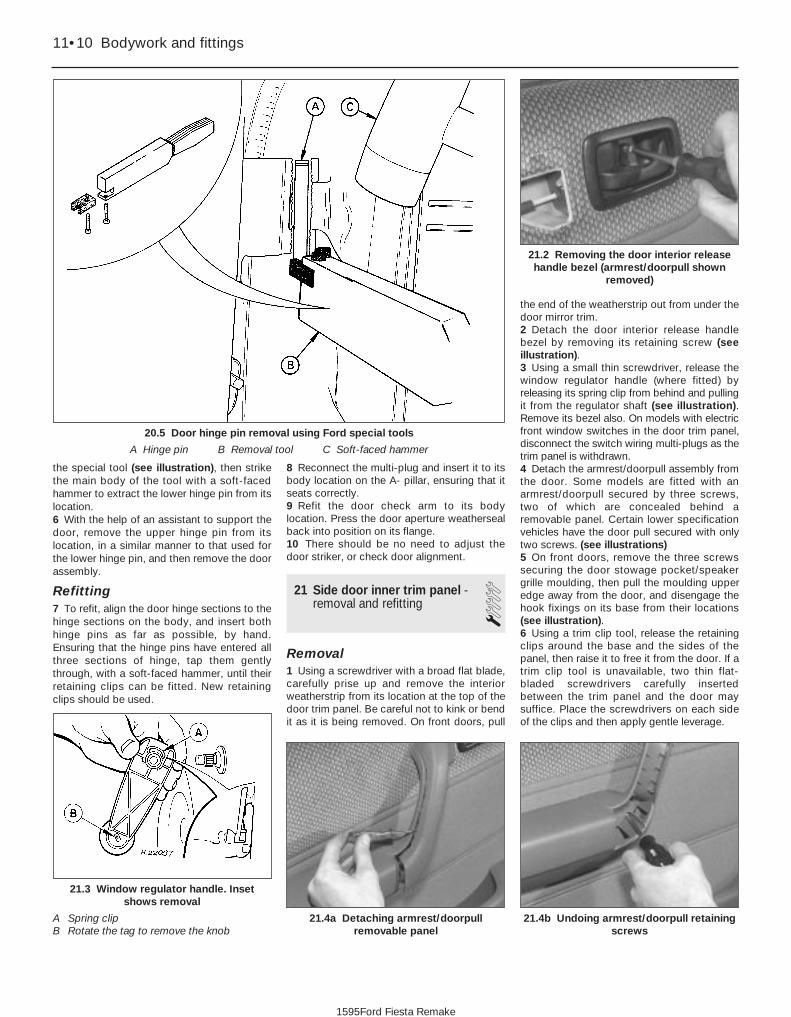
the special tool (see illustration), then strikethe main body of the tool with a soft-facedhammer to extract the lower hinge pin from itslocation.6 With the help of an assistant to support thedoor, remove the upper hinge pin from itslocation, in a similar manner to that used forthe lower hinge pin, and then remove the doorassembly.
Refitting7 To refit, align the door hinge sections to thehinge sections on the body, and insert bothhinge pins as far as possible, by hand.Ensuring that the hinge pins have entered allthree sections of hinge, tap them gentlythrough, with a soft-faced hammer, until theirretaining clips can be fitted. New retainingclips should be used.
8 Reconnect the multi-plug and insert it to itsbody location on the A- pillar, ensuring that itseats correctly.9 Refit the door check arm to its bodylocation. Press the door aperture weathersealback into position on its flange.10 There should be no need to adjust thedoor striker, or check door alignment.
21 Side door inner trim panel -removal and refitting 1
Removal1 Using a screwdriver with a broad flat blade,carefully prise up and remove the interiorweatherstrip from its location at the top of thedoor trim panel. Be careful not to kink or bendit as it is being removed. On front doors, pull
the end of the weatherstrip out from under thedoor mirror trim.2 Detach the door interior release handlebezel by removing its retaining screw (seeillustration).3 Using a small thin screwdriver, release thewindow regulator handle (where fitted) byreleasing its spring clip from behind and pullingit from the regulator shaft (see illustration).Remove its bezel also. On models with electricfront window switches in the door trim panel,disconnect the switch wiring multi-plugs as thetrim panel is withdrawn.4 Detach the armrest/doorpull assembly fromthe door. Some models are fitted with anarmrest/doorpull secured by three screws,two of which are concealed behind aremovable panel. Certain lower specificationvehicles have the door pull secured with onlytwo screws. (see illustrations)5 On front doors, remove the three screwssecuring the door stowage pocket/speakergrille moulding, then pull the moulding upperedge away from the door, and disengage thehook fixings on its base from their locations(see illustration).6 Using a trim clip tool, release the retainingclips around the base and the sides of thepanel, then raise it to free it from the door. If atrim clip tool is unavailable, two thin flat-bladed screwdrivers carefully insertedbetween the trim panel and the door maysuffice. Place the screwdrivers on each sideof the clips and then apply gentle leverage.
11•10 Bodywork and fittings
21.4b Undoing armrest/doorpull retainingscrews
21.4a Detaching armrest/doorpullremovable panel
21.3 Window regulator handle. Insetshows removal
A Spring clipB Rotate the tag to remove the knob
21.2 Removing the door interior releasehandle bezel (armrest/doorpull shown
removed)
1595Ford Fiesta Remake
20.5 Door hinge pin removal using Ford special tools
A Hinge pin B Removal tool C Soft-faced hammer

Refitting7 To refit, first align the trim panel to the door,secure its upper edge into its hook fastenings,then press into position to engage the trimclips. Where electric window switches arefitted, reconnect the switch wiring multi-plugsbefore fitting the panel.8 If necessary, refit the clip to the windowregulator handle, then refit the handle to theregulator shaft by pushing it on. The clipshould engage positively, in the annulargroove on the shaft.9 Refit the door stowage pocket/speakergrille moulding, armrest/doorpull and doorinterior release handle bezel, as applicable, byreversing the method of removal.10 Refit the interior weatherstrip to itslocation, tapping it down into position, beingcareful not to bend or kink it. On front doors, itwill be necessary to slide its forward edgeunder the door mirror trim before tapping intoposition.
22 Side door lock, lock cylinderand handles - removal andrefitting 2
Exterior handle
Removal1 Remove the door inner trim panel, asdescribed in Section 21.2 Locally detach the PVC sheet from the doorto allow access into the door cavity. Do nottear the sheet; cut closely around the clips, asrequired.3 Disconnect the handle operating rod fromthe latch assembly, by twisting the clip andwithdrawing the rod, as applicable.4 Remove the two screws securing thehandle then, from the outside, withdraw the handle and rod, guiding the rod outthrough the door skin as necessary (seeillustrations). The handle and rod may bedisconnected as required.
Refitting5 Refitting is a reversal of the removalprocedure. On completion, re-secure the PVCsheet then refit the inner trim panel asdescribed in Section 21.
Door lock barrel
Removal6 Remove the door inner trim panel, asdescribed in Section 21.7 Locally detach the PVC sheet from the doorto allow access into the door cavity. Do nottear the sheet; cut closely around the clips, asrequired.8 Drill out the rivets securing the door glassguide above the lock barrel, and remove it.9 Disconnect the lock barrel operating rodfrom the latch assembly, by twisting the clipand withdrawing the rod.10 Release the lock barrel retaining clip bywithdrawing it upwards, then from theoutside, withdraw the lock barrel and rod,guiding the rod out through the door skin. Thelock barrel and rod may be disconnected asrequired.
Refitting11 Refitting is a reversal of the removalprocedure. Ensure that the lock barrel gasketis located correctly between the lock barrelouter surround and the door skin, and that the
door glass guide is riveted securely. Checkthat the window operates smoothly andcorrectly, by temporarily refitting the regulatorhandle or operating the electric windowmotor.12 On completion, re-secure the PVC sheetthen refit the inner trim panel as described inSection 21.
Door latch and interior releasehandle
Removal13 Remove the door inner trim panel, asdescribed in Section 21.14 Locally detach the PVC sheet from thedoor to allow access into the door cavity. Donot tear the sheet; cut closely around theclips, as required.15 On rear doors fitted with central locking,undo the two screws securing the rod guardand remove it (see illustration).16 Disconnect the operating rods from thelatch assembly as necessary. On rear doorswith central locking, disconnect and releasethe motor loom multi-plug assembly, andwithdraw the motor side of the loom back intothe door cavity. Undo the three screwssecuring the motor assembly, disengage itsoperating rod and remove it from the vehicle(see illustration).
Bodywork and fittings 11•11
22.4b Removing the door exterior handle,guiding its operating rod out through the
door skin (front door)
22.4a Door exterior handle and lock barrelsecuring arrangements (front door)
A Handle screw locationsB Lock barrel retaining clip
21.5 Disengaging the hook fixings on thebase of the door stowage pocket/speaker
grille moulding
22.16 Central locking motor retainingscrews (A), and loom multi-plug
assembly (B) on rear door
22.15 Rod guard securing screws(arrowed) on rear doors with central
locking only
11
1595Ford Fiesta Remake

17 On front doors, vehicles fitted with centrallocking have a latch with an integral motor. Ifcentral locking is fitted, prise up and twist therearward clips securing the motor loom to thedoor, to free the loom, disconnect the multi-plugs and withdraw the loom (motor side)back into the door cavity.18 Remove the interior release handlesurround, then prise up the forward end of thehandle unit. Release the handle from itsrearward location by sliding it forward todisengage the hooks (see illustration).19 Detach the door interior release cablefrom its retaining clips on the door panel.20 Remove the latch securing screws fromthe upper rear edge of the door, and with-draw the latch and interior release mechanismfrom the vehicle (see illustration).21 Remove the cable cover from the latchassembly, then detach the cable from thelatch.22 Peel the sponge pad from the reverse sideof the interior release handle, and remove theouter cable from its abutment in the body ofthe handle. Remove the inner cable core byaligning the core with the slot by its end fixing,then slide the end fixing out.
Refitting23 Refitting is a reversal of the removalprocedure. On completion, re-secure the PVCsheet then refit the inner trim panel asdescribed in Section 21.
23 Tailgate support strut -removal and refitting 1
Removal1 Open the tailgate and support it securely,using a length of timber, or have an assistanthold it open.2 Detach the support strut by raising theretaining clip and pulling the strut away fromits ball stud fixing on the tailgate. Do not raisethe clip more than 4.0 mm, or the supportstrut will be damaged.3 Repeat the operation on the other end ofthe support strut.
Refitting4 To refit, align the thicker (cylinder) end ofthe support strut to the ball stud fixing on thetailgate, then push until it snaps intoengagement.5 Repeat the operation with the thinner(piston) end of the support strut to the ballstud fixing on the body.
24 Tailgate -removal and refitting 1
Removal1 Open the tailgate and mark around thehinge positions on the tailgate panel itself.2 Remove the central blanking plug from theupper portion of the tailgate to expose thewasher jet, and disconnect the washer hosefrom the jet base, as applicable. Free thewasher hose grommet and withdraw the hosefrom the tailgate.3 Disconnect the support strut from thetailgate, as described in Section 23.4 With the aid of an assistant, undo the fourbolts securing the tailgate to the vehicle bodyand remove the tailgate.
Refitting5 To refit, align the hinges on the body withthe marks made on the tailgate panel, thenrefit and tighten the four bolts to secure. Refitthe support strut as described in Section 23.6 The remainder of the refitting operation is areversal of the removal procedure.7 Close the tailgate and check the alignment.Adjust as necessary to obtain an even gapbetween the tailgate and all adjacent panels.
25 Tailgate spoiler - removal and refitting 2
Removal1 Drill out the rivets securing the outer edgesof the spoiler to the tailgate.
2 Open the tailgate and remove the fourblanking plugs covering the spoiler retainingnuts. Undo the nuts and remove the spoiler.
Refitting3 To refit, first align the spoiler mountingstuds to their tailgate fixing holes, then rivetthe outer edges of the spoiler to the tailgate.4 Refit the four retaining nuts and tighten tothe specified torque.5 Refit the blanking plugs.
26 Tailgate inner trim panel -removal and refitting 1
Removal1 Open the tailgate then, using a screwdriver,remove the seven plastic retaining screwsfrom the trim panel.2 Remove the square plastic clip from thetrim panel.3 Disengage the clips from the panel edgenearest the window, and manoeuvre the panelto release the hooks on the other panel edge.Withdraw the trim panel from the vehicle.
Refitting4 Refitting is a reversal of removal.
27 Tailgate lock components -removal and refitting 2
Note: For vehicles equipped with remotetailgate release, removal and refittingprocedures for the tailgate remote releasemotor are contained in Chapter 12.
Removal1 Remove the tailgate inner trim panel asdescribed in Section 26.2 Remove the two Torx screws securing thetailgate latch, then pull it down, disconnect itsoperating rod and remove the latch from thevehicle (see illustration).3 Remove the bolt securing the lock barrel
11•12 Bodywork and fittings
27.2 Tailgate latch and its Torx securingscrews (arrowed)
22.20 Removing the latch securing screws(arrowed)
22.18 Detaching the interior door releasehandle
1595Ford Fiesta Remake

retainer to the tailgate, then withdraw theretainer (see illustration).4 Remove the lock assembly from the tailgateby partially withdrawing the lock, twisting it sothat the lock rod can be removed, then fullywithdrawing.
Refitting5 To refit, first ensure that the lock gasket isin position, then partially insert the lock intothe tailgate and reconnect the lock rod. Fullyinsert the lock and refit its retainer andsecuring bolt.6 Using an electrician’s thin screwdriver,prise up the lever on the latch and fit the lockrod to it, ensuring that it fully engages.7 Align the latch with its location and refit itstwo securing screws.8 Check for correct lock operation beforerefitting the tailgate interior trim panel asdescribed in Section 26.
28 Rear doors (Courier models)- removal and refitting 1
Removal1 Open the door and disconnect the wiringleading to it; all connectors are accessiblefrom the openings inside the door frame.
2 Unclip the door check arm, and unscrewthe bottom hinge’s cap securing bolt (seeillustration).3 Lift the door off its hinges and withdraw it.
Refitting4 Refitting is the reverse of the removalprocedure; apply grease to the hinge pins,and tighten the cap bolt securely.5 The door hinges can be unbolted from thedoor and frame; either remove the door first,or support it carefully and remove the hingewith it in place.
29 Rear door inner trim panels(Courier models) - removal and refitting 1
Removal1 Remove the interior handle bezel bypushing it away from the door’s hinges until itcan be withdrawn.2 Using either a trim clip releasing tool or ascrewdriver with a broad flat blade, andprotecting the paintwork and trim with a layerof rag, extract the clips securing the panel andwithdraw it.
Refitting3 Refitting is the reverse of the removalprocedure.
30 Rear door lock, catches andhandles (Courier models) -removal and refitting
1Interior handle
Removal1 Remove the inner trim panel, as describedin Section 29.2 Remove its four retaining screws, andwithdraw the complete latch assembly (seeillustrations).3 Disconnect the link rod and remove thesingle retaining screw to withdraw the interiorhandle.
Refitting4 Refitting is the reverse of the removalprocedure.
Exterior handle and lockassembly
Removal5 Remove the inner trim panel, as describedin Section 29.6 Remove its four retaining screws, andwithdraw the complete latch assembly.7 Using pliers, rotate the exterior handlelocking ring anti-clockwise to release it, thenwithdraw the handle with the inner and outergaskets (see illustrations).8 The lock assembly is secured by a circlip tothe handle.
Bodywork and fittings 11•13
30.2a Courier rear door latch assemblyretaining screws (arrowed)
28.2 Unscrewing the bottom hinge’s capsecuring bolt on Courier rear door
27.3 Tailgate lock retention arrangement
A Lock barrel retainer securing boltB Lock barrel retainer
30.7b . . . to release Courier rear doorexterior handle
30.7a Release locking ring and withdrawgaskets . . .
30.2b Latch assembly released -disconnect cables to withdraw
11
1595Ford Fiesta Remake

Refitting9 Refitting is the reverse of the removalprocedure.
Upper and lower door catches
Removal10 Remove the inner trim panel, as describedin Section 29.11 Remove its four retaining screws, andwithdraw the complete latch assembly.Disconnect the upper and lower catch cables
from the latch assembly operatingmechanism.12 Unbolt the catch and withdraw it from thedoor (see illustration). If the cables areavailable separately (seek the advice of a Forddealer) they can be disconnected from eachcatch by releasing the retaining clip.
Refitting13 Refitting is the reverse of the removalprocedure; check the adjustment of the catchbefore finally tightening the bolts.14 The striker plates can be adjusted on theirslotted mounting bolt locations, if required.
31 Door window regulator -removal and refitting 3
Manual front regulator
Removal1 Remove the door inner trim panel, asdescribed in Section 21.2 Locally detach the PVC sheet from the doorto allow access into the door cavity. Do not
tear the sheet; cut closely around the clips, asrequired.3 Remove the door window glass, asdescribed in Section 32.4 Drill the heads off the regulator securingrivets and manoeuvre the regulator assemblyfrom the door (see illustration). Lay theregulator body in the bottom of the door, thenwithdraw the gear mechanism and cablefollowed by the rigid “pillar”.
Refitting5 Refit the regulator by reversing the methodof removal, ensuring that it is securely rivetedto the door.6 Refit the door window glass, as describedin Section 32.7 Re-secure the PVC sheet then refit the doorinner trim panel as described in Section 21.
Electric front regulator
RemovalNote: For motor removal and refittingprocedure, refer to Chapter 12.8 Remove the door inner trim panel, asdescribed in Section 21.9 Locally detach the PVC sheet from the doorto allow access into the door cavity. Do nottear the sheet; cut closely around the clips, asrequired.10 Remove the door window glass, asdescribed in Section 32.11 Disconnect the multi-plug on the regulatormotor body, and remove the three nutssecuring the motor/winding mechanismsection of the assembly to the door.12 Drill the heads off the regulator securingrivets and manoeuvre the regulator assemblyfrom the door. Lay the regulator body in thebottom of the door, then withdraw the gearmechanism and cable followed by the rigid“pillar”.
Refitting13 To refit, first position the regulatorassembly in the door, and refit the three nutssecuring the motor/winding mechanismsection.14 Re-rivet the pillar section of the regulatorassembly securely to door.15 Reconnect the multi-plug to the regulatormotor body.16 Refit the door window glass, as describedin Section 32.17 Re-secure the PVC sheet then refit thedoor inner trim panel as described in Sec-tion 21.
Rear regulator
Removal18 Remove the door inner trim panel, asdescribed in Section 21.19 Locally detach the PVC sheet from thedoor to allow access into the door cavity. Donot tear the sheet; cut closely around theclips, as required.20 Drill the heads off the four regulatorsecuring rivets, and remove the two lower
11•14 Bodywork and fittings
31.4 Window regulator assembly (manual, front)
30.12 Courier rear door lower catchremoval
1595Ford Fiesta Remake
A Window glass liftingchannel
B Regulator assemblyC RivetsD Screws

window glass guide securing screws (seeillustration).21 Support the window glass then, havingpushed the regulator into the door cavity,disconnect the regulator arm from it. Removethe regulator assembly.
Refitting22 Refitting is a reversal of the removalprocedure, ensuring that the window regulatoris securely riveted to the door. Check theoperation of the window regulator, bytemporarily refitting the regulator handle and,if necessary, adjust the window glass guide toensure that the window glass does not stickor judder.23 Re-secure the PVC sheet then refit thedoor inner trim panel as described in Sec-tion 21.
32 Door window glass - removal and refitting 3
Front side door glass
Removal1 Remove the door inner trim panel, asdescribed in Section 21.2 Locally detach the PVC sheet from the doorto allow access into the door cavity. Do nottear the sheet; cut closely around the clips, asrequired.3 Remove the door belt weathersealmoulding as described in Section 10.4 Remove the two screws securing thewindow glass lifting channel to the regulatorassembly, through either their upper or loweraccess holes. Support the glass as the screwsare removed.5 Remove the window glass by tilting itforwards towards the hinge end of the door,then withdraw it towards the latch end.
Refitting6 To refit, position the window glass into thedoor by reversing the method of removal.7 Loosely refit the two screws to hold thewindow glass lifting channel to the regulator
assembly, but do not tighten them at thisstage.8 Raise the window glass fully, then tightenthe retaining screws through their upperaccess holes. This ensures correct positioningof the window glass in its aperture.9 Refit the door belt weatherseal moulding asdescribed in Section 10.10 Re-secure the PVC sheet then refit thedoor inner trim panel as described in Sec-tion 21.
Rear side door sliding glass
Removal11 Remove the door window regulator, asdescribed in Section 31, then fully lower thewindow glass into the door.12 Remove the door belt weathersealmouldings in a similar manner to thatdescribed in Section 10.13 Remove the remaining two window glassguide securing screws from their location atthe top of the door, and disengage the top of the guide.14 Manoeuvre the fixed rear quarter windowglass forwards and out from its location, alongwith the window glass guide. Lift out theplastic strip.15 Manoeuvre the door window glass up andout of the door, from the exterior side of thedoor.
Refitting16 Refitting is a reversal of the removalprocedure, ensuring that the fixed rear quarterwindow seats correctly in its location, and thatthe window glass guide holds the windowglass correctly (refer to Section 31).
Rear side door fixed quarterglass17 The fixed rear quarter window glass isremoved and refitted in conjunction with therear side door sliding glass describedpreviously in this Section.
Rear door glass (Couriermodels)18 The rear door window glass on Couriermodels is removed and refitted using thesame technique as for the fixed side windowglass described in Section 33.
33 Side window glass - removal and refitting 3
Fixed side window glassRemoval1 The lip of the weatherseal surrounding thewindow glass must be released from the topand sides of the body aperture flange, using asuitable tool, before exerting pressure fromthe inside of the vehicle to remove the glass.Any surrounding interior trim should beremoved. It is important that an assistant
helps and holds the glass from the outside asit is pressed out from the inside.2 With the assembly removed from thevehicle, detach the weatherseal from thewindow glass.3 If the weatherseal is to be re-used it shouldbe cleaned. Do not use petrol, white spirit orother similar substances, as they may causerapid rubber deterioration. Ensure that theglass groove in the weatherseal is free fromany sealant or glass fragments.4 Ensure that the body aperture flange is freefrom any sealant also.
Refitting5 Commence refitting by attaching theweatherseal to the window glass, ensuringthat it is seated correctly.6 Insert a length of nylon or terylene cord intothe body aperture flange groove of theweatherseal, so that the cord ends emerge atthe top centre of the window, and overlap byapproximately 150.0 mm.7 Offer the assembly to the body aperture,and engage the lower lips of the weathersealover the body aperture flange. Ensure that theengagement of the weatherseal lips is nothampered in any way, and that the cord endsare protruding inside the vehicle.8 With an assistant applying a gentle evenpressure on the window glass from theoutside, pull one end of the cord at right-angles to the glass. This will pull the inner lipof the weatherseal over the body apertureflange.9 When the cord has been pulled halfwayaround the aperture, repeat the procedurewith the other end of the cord. The cordshould release when the window glass is fullyfitted.10 Refit any disturbed interior trim asnecessary.
Hinged side window glassRemoval11 With an assistant standing outside readyto take the window, unscrew the single screwsecuring each hinge, then open the windowand unscrew the two screws securing thecatch to the body. Withdraw the window.12 The weatherstrip can now be removedand refitted, if required.
Refitting13 To refit the window, have your assistantstand outside and offer up the window so thatboth hinge leaves enter their sockets, thenloosely refit the catch securing screws. Refitthe hinge securing screws, then adjust thecatch position to ensure that the window isclamped evenly on to the weatherstrip overthe whole mating surface when the catch isfastened. Tighten all screws securely.
Sliding side window and glassRemoval14 To remove the complete sliding windowassembly on Courier Kombi models requiresspecial cutting equipment and supplies of
Bodywork and fittings 11•15
31.20 Regulator retaining rivets (A) andlower window glass guide securing
screws (B) on rear door
11
1595Ford Fiesta Remake

suitable adhesive; it is recommended that thistask be left to a Ford dealer or similar expert.15 To remove the window glass, remove theirretaining screws and withdraw the lockassemblies, slide the front glass as far to therear as possible, then prise up and withdrawthe front glass guide; it will be necessary topull the last part of the guide from under theglass.16 Withdraw the vertical seal and twosupport blocks from between the two glasses,slide the seal to the front of the frame, andwithdraw it. Slide each glass in turn to the front of the frame and withdraw it, then prise up and withdraw the rear glassguide.
Refitting17 On refitting, check that the glass guidesare undamaged; renew them if necessary.Ensure that the lock assemblies are removedfrom both glasses.18 Press the rear glass guide into place. Refitfirst the rear glass, fitting it to the front of theframe and sliding it to the rear, then the frontglass, in the same way.19 To refit the vertical seal, sandwich itbetween two strips of thin sheet metal andinstall it, with its support blocks, first in thefront part of the frame, then push it into place.This will require some effort as the glass isreached, due to the distortion caused by thelocation notch on the block. When the seal isfully in place, withdraw the metal strips, andcheck that the seal’s lips have not folded backon themselves.20 When refitting the front glass guide, locateit first around the frame’s detent catch, thenslide it under the glass using soapy water as alubricant.21 Refit the lock assemblies, clean theglasses, and check the operation of thewindows and locks.
34 Windscreen and tailgatewindow glass - removal and refitting
4Note: The DIY mechanic is advised to leavewindscreen/tailgate window glass removaland refitting to an expert. For those with thenecessary tools and equipment, the following paragraphs are a guide to theprocedure.
Removal1 Remove the windscreen/tailgate wiper armsas described in Chapter 12.2 If removing the windscreen, remove both A-pillar trims, and release the front of theheadlining by removing the sun visors andcourtesy light. If a heated windscreen is fitted,disconnect its electrical contacts at thewindscreen. If removing the tailgate windowglass, disconnect the wiring to the heatingelement.
3 As a precautionary measure to preventdamage to the paintwork, cover thesurrounding bodywork with an old blanket orsimilar.4 Using a suitable tool, release theweatherseal from the top and sides of thebody aperture flange before exerting pressurefrom the inside of the vehicle to remove theassembly. It is strongly advised that anassistant outside the vehicle is ready toreceive the glass as it is pushed out.5 With the assembly removed from thevehicle, detach the weatherseal from thewindscreen/tailgate glass.
Refitting6 With reference to the procedures describedfor the fixed side window glass in Section 33,clean the weatherseal, then refit inaccordance with the rest of that Section.7 Any trim and equipment removed duringpreparation should now be refitted.
35 Sunroof panel - removal and refitting 1
Removal1 Open the sunroof fully using the handwheel.2 Detach the sunroof from its rearwardmounting point by pressing in the red lockingbar on the handwheel, then raise it andremove.
Refitting3 To refit, engage the hinges in theirlocations, in the forward edge of the sunroofopening, then lower the sunroof. Allow thehandwheel to click into its safety lock.4 Check that the safety lock mechanismretains the panel securely.5 Close the sunroof fully using thehandwheel.
36 Sunroof panel seal - renewal 1
1 Remove the sunroof panel, as described inSection 35, then lay the panel on a soft cloth.2 Remove the two hinge plate assembliesfrom the panel by undoing the hinge plateretaining screws.3 Pull the seal from the panel edge, noting theposition of its join.4 Starting from the position of the originaljoin, press the seal into position, ensuring thatit sits evenly right around. Adjust as necessaryso that the ends butt tightly together.5 Refit the two hinge plate assemblies to thepanel.6 Refit the sunroof panel, as described inSection 35.
37 Sunroof weatherseal -removal and refitting 1
Removal1 Remove the sunroof panel, as described inSection 35.2 Starting from the joint on the rearwardopening edge, pull the seal up and remove.
Refitting3 Refitting is a reversal of the removalprocedure, ensuring that the weathersealdoes not deform at the corners, or split at thejoint.
38 Full-length sunroof - general information
1 The full-length sunroof is electrically-operated, the operating system consisting ofthe motor and the roof-mounted switch. Thecircuit is fed via fuses 18 and 28 from theignition switch; switch illumination is via fuse 6.2 All components are mounted in the roof ofthe passenger compartment, above theheadlining at the front of the vehicle.3 To open the sunroof, press the switchlightly on the upper side; to close it, checkfirst that the opening is completelyunobstructed, and press the switch on thelower side.4 Maintenance is confined to checking forfreedom of action and a snug fit when shut.Check that the seals are in good cleancondition and not scratched or damaged.5 Owners must note the following to ensurethat the maximum trouble-free life from thisfeature:a) It is normal for the motor to slow down as
the sunroof approaches full opening.b) If the sunroof stops before it is fully
opened in cold weather, this may be dueto the material being too hard to foldcorrectly; do not force the sunroof open ifthis is suspected.
c) If the material does not fold correctly onopening at any time, close the sunroofagain, correct the folds by hand, and tryagain.
d) Never open or close the sunroof with thevehicle travelling at more than 70 mph(120 km/h), and never allow passengers totravel standing up or with any part of theirbodies in the opening.
e) Ensure that any collected water, snow orice is removed from the sunroof beforeopening it. Check that the deflector isclear of water, particularly after washingthe vehicle; sponge it dry if necessary.
f) Never place heavy objects on the sunroofor its surrounds.
g) The sunroof should be cleaned frequently
11•16 Bodywork and fittings
1595Ford Fiesta Remake

to avoid the material being stained by dirt.Use a sponge, soft brush or soft cloth anda neutral detergent, rinsing with a gentleflow of clean water from directly aboveuntil all traces of dirt and detergent areremoved. Never use a high-pressure jet,pressure washer or similar, and do notaim the jet from a hose at the joints of thesunroof with the body (or water will enterthe passenger compartment). Never usealcohol, petrol, thinners or similarproducts to clean the material.
h) If the vehicle is parked in heavy rain, or if itis parked outside for long periods, aproprietary car cover or tarpaulin shouldbe used to protect the roof and body. Donot leave the sunroof open for longperiods; the material will stiffen in its folds,with a consequent risk of tearing when thesunroof is eventually operated again.
6 If the system fails with the sunroof open, itcan be closed in emergency by switching offthe ignition, prising out the access plug infront of the switch, and using the crankprovided to rotate the motor shaft clockwiseuntil the roof is closed.7 If the switch is thought to be at fault, it canbe removed after first disconnecting thebattery negative (earth) lead (refer to Chap-ter 5, Section 1) ; the switch can then beeased from its housing until the wires can bedisconnected. Refitting is the reverse of theremoval procedure.8 If any other failure or problem isencountered, the general inaccessibility of thesystem’s components means that servicingand fault-finding is beyond the capabilities ofmost owners; the vehicle should be taken to aFord dealer for attention.
39 Front seat and slideassembly - removal and refitting
1Removal
Warning: On vehicles fitted withmechanical seat belt pre-tensioning stalks, be carefulwhen handling the seat, as the
tensioning device (“grabber”) contains apowerful spring, which could cause injuryif released in an uncontrolled fashion. Thetensioning mechanism should beimmobilised by inserting a safety “transitclip” available from Ford parts stockists.You are strongly advised to seek theadvice of a Ford dealer as to the correctuse of the “transit clip” and the safetyimplications before proceeding.1 On pre-1994 models, slide the seat fullyrearwards to expose the two front slideassembly to floorpan bolts. Remove all fourbolts securing the slides to the floorpan, andremove the seat from the vehicle.2 On later models, pull off the trim cover fromthe outer slide.
3 On vehicles fitted with mechanical seat beltpre-tensioning stalks, fit the safety “transitclip”.4 Slide the seat fully rearwards, remove theinner slide trim cover then unscrew andremove the front slide assembly to floorpanbolts.5 Now slide the seat fully forward, andunscrew the rear slide securing bolts eachside. Lift the seat and remove it from thevehicle.
Refitting6 Position the seat in the vehicle, and alignthe slide assemblies with their mounting boltlocations in the floorpan. Refit the frontsecuring bolts first, followed by the rear securing bolts, to ensure that the seatruns smoothly in its slide mechanism. Tightenthe bolts to the specified torque. On latermodels, remove the “transit clip” (whereapplicable) and refit the trim covers.
40 Rear seat - removal and refitting 1
Backrest and catchRemoval1 To remove the backrest, release thebackrest catch/catches, then fold thebackrest forwards.2 Remove the hinge-to-backrest securingscrews, then remove the backrest (seeillustration).3 The hinges may be removed at this stage ifrequired, by undoing the hinge-to-bodysecuring screws.4 If desired, the rear seat backrest catch maybe removed by removing the catch retainingbolts (see illustration).
Refitting5 If removed, refit the backrest catch andsecure with the retaining bolts.6 To install the backrest, align the hinges tothe body and backrest, then loosely refit thesecuring screws.
7 Fold the backrest into its upright positionand engage the backrest catch/catches.Adjust the alignment of the components then,when correct, tighten the securing screws totheir specified torques.8 Check for correct catch engagement.
Cushion
Removal9 To remove the cushion, remove the threescrews securing the forward edge of the seatcushion to the raised floorpan section.10 Push down and back on the cushion, todisengage the hook and catch on the rearunderside of the seat.11 Remove the seat from the vehicle afterguiding the seat belt clips through the slits inthe seat cushion.
Refitting12 Refitting the cushion is a reversal of theremoval procedure.
Seat assembly (Courier Kombimodels)
Removal13 The seats are secured by two bolts ateach forward hinge, visible once the seat hasbeen folded forwards. Unbolt the hinges andwithdraw the seat assembly.
Refitting14 Refitting is the reverse of the removalprocedure.
41 Seat belts - removal and refitting 3
Removal
Front seat belt (five-door models)1 Remove the cover from the upper anchorposition and remove the anchor bolt.2 Remove the lower anchor bolt from itslocation on the floor by the base of the B-pillar. Prevent the retractor unit from reeling intoo great a quantity of seat belt by attaching aclothes peg, or similar item, to the seat belt.
Bodywork and fittings 11•17
40.4 Rear seat backrest catch retainingbolts (arrowed)
40.2 Rear seat hinge arrangement
A Hinge-to-backrest screw locationsB Hinge-to-body screw locations (removed
after backrest detached)
11
1595Ford Fiesta Remake

3 Remove the B-pillar trim and sill scuff plateas described in Section 42.4 Remove the bolt (two bolts on later models)securing the seat belt retractor unit to itslocation in the base of the B-pillar (seeillustration), then remove the retractor unitand the seat belt from the vehicle.
Front seat belt (three-door models)5 Remove the rear quarter trim panel, asdescribed in Section 42.6 Undo the bolt securing the seat beltretractor unit to its location, then remove theretractor unit and seat belt from the vehicle.
Front seat belt (Van models)7 Remove the cover from the upper anchorposition and remove the anchor bolt.8 Undo the bolt securing the retractor unitand integral lower anchor position, thenremove the retractor unit and seat belt fromthe vehicle.
Front seat belt stalkWarning: On vehicles fitted withmechanical seat belt pre-tensioners, any work on the seatbelt stalk should be entrusted to
a Ford dealer. The following procedure istherefore only applicable to models with
conventional seat belt stalks which DONOT incorporate any form of pre-tensioning device. 9 Remove the bolt securing the seat belt stalkassembly to the floor, between the two frontseats, noting the arrangement of washers andspacers (see illustration). Remove the stalkassembly from the vehicle.
Front seat belt height adjuster Note: If a height adjuster mechanism is notfitted, it is possible to lower the upper anchorposition from its production setting, byremoving the plug from the lower adjusterplate hole and bolting the anchor into this (seeillustration 41.13). The plug can then be fittedto the production setting hole.10 Remove the height adjuster knob bycarefully inserting a small screwdriver into theaperture on the underside of the knob, andgently levering it off.11 Remove the anchor cover, again using ascrewdriver, then remove the anchor bolt andanchor (see illustration).12 Remove the door aperture weatherseal(s)around the B-pillar location, then remove theB-pillar trim, as described in Section 42.13 Remove the bolts securing the adjusterplate to the B-pillar, noting washer fitment,
then remove the adjuster plate from thevehicle (see illustration).
Rear seat belts14 Remove the rear seat cushion, asdescribed in Section 40, then also remove theparcel shelf.15 Undo the bolt securing each seat beltbuckle assembly to its body location (seeillustration), and remove the buckleassemblies from the vehicle, as required.16 Prevent the retractor units from reeling intoo much seat belt by attaching a clothes pegor similar item to the belt, close to theretractor unit.17 Detach the seat belt lower anchor byremoving its retaining bolt.18 Remove the upper anchor bolt cover andundo the bolt securing the anchor to itslocation. Detach the anchor, noting anyspacer fitment.19 On vehicles fitted with a parcel shelf,remove the seat belt guide from the parcelshelf support/rear loudspeaker housing, thenpass the seat belt through it.20 On vehicles without a parcel shelf asstandard, remove the trim panel covering theseat belt retractor unit, where fitted, byundoing its retaining screws. Remove the seatbelt guide from the trim panel, then pass theseat belt through it.21 Remove the bolt securing the seat beltretractor unit to its body location, thenwithdraw the retractor unit and the seat beltfrom the vehicle.
Refitting22 Refitting is a reversal of the removalprocedure, noting the following points. Ensurethat the tag on the retractor unit engages in itsbody location and, in the case of the rear seatbelts, that it does not trap the wiring loombetween itself and the body. Having fitted theupper anchor to its location, ensure that it canrotate freely. The stalk assembly anchor(s)must engage to the anti-rotation floorpin(s)and, when refitting a rear centre lapbelt/buckle assembly, the lap belt must befitted to lie on the right-hand side of thevehicle. Tighten all bolts to their specifiedtorque.
11•18 Bodywork and fittings
41.15 Rear seat belt and buckle securingarrangements (rear seat cushion removed)
A Seat belt lower anchor retaining boltsB Centre lap belt/single buckle assembly
securing boltC Dual buckle assembly securing bolt
41.13 Seat belt upper anchor position(fixed and adjustable)
A Adjuster plate securing boltB Anchor bolt position (production setting)C Lower setting for fixed type (if required)
41.11 Removing a seat belt upper anchorcover
41.9 Front seat belt stalk assembly
A BoltB Anti-rotation plateC Stalk
D Metal washersE Paper washerF Floorpin
41.4 Seat belt retractor unit location inbase of B-pillar (five-door models)
A Retractor unit locating tagB Retractor unit securing bolt
1595Ford Fiesta Remake

42 Interior trim panels - removal and refitting 2
A-pillar trim
Removal1 Remove the securing screw from the trimpanel, located near to the windscreen topcorner (see illustration).2 Detach the door aperture weatherseal fromaround the trim panel, then pull the trim panelfrom the pillar.
Refitting3 To refit, align the trim fixing lugs to the pillarand press into position. Refit the securingscrew then push the door apertureweatherseal back onto its flange.
B-pillar trim
Removal4 Remove the front seat belt height adjusterknob, as applicable, by inserting a smallscrewdriver into the aperture on the undersideof the knob and levering it off.5 Remove the upper seat belt anchor boltcover, and remove the bolt, as required.6 Open the doors and detach the dooraperture weatherstrip from the area aroundthe B-pillar trim.
7 Remove the securing screws and detachthe trim.
Refitting8 Refitting is the reverse sequence toremoval, tightening the seat belt anchor boltto the specified torque. Ensure that theanchor is free to rotate.
C-pillar trim
Removal9 Open the tailgate, then detach theloudspeaker from its location bydisconnecting its multi-plug connection,removing its two retaining screws andunhinging it.10 Detach the tailgate weatherstrip from itsflange, around the trim panel.11 Remove the parcel shelf, then slacken theparcel shelf support/rear loudspeaker housingretaining screws, and remove the single screwfrom the base of the C-pillar trim (seeillustration).12 Remove the upper seat belt anchor boltcover, and remove the bolt and anchor, notingany spacer fitment.13 Remove the screw(s) from the top of theC-pillar trim, then remove the trim from thevehicle.
Refitting14 To refit, position the base of the trim
behind the parcel shelf support/rearloudspeaker housing, then loosely refit theupper and lower securing screws.15 Refit the seat belt anchor, bolt, andspacer, as applicable, tightening the bolt tothe specified torque. Refit the anchor boltcover, and ensure that the anchor is free torotate.16 Tighten the trim and parcel shelfsupport/rear loudspeaker housing screws,then refit the parcel shelf.17 Refit the loudspeaker by reversing themethod of removal, then press the tailgateweatherstrip back into place.
Sill scuff plate
Removal18 Remove the front seat adjacent to thescuff plate to be removed (see Section 39).19 Detach the door aperture weatherstrip(s)from around the scuff plate location.20 Remove the B-pillar trim, as applicable.21 Remove the lower seat belt anchor bolt onfive-door models, and detach the anchor fromits location.22 On three-door models, remove the boltsecuring the forward end of the seat belt slidebar, then manoeuvre the slide bar to free itfrom its rear location.23 Remove the plastic screws securing thesill scuff plate, then slip the seat belt throughits slot on five-door models, and remove thesill scuff plate from the vehicle (seeillustration). Should the soft plastic screwsround off during attempts to remove them,force an electrician’s thin screwdriver into thebody of the screw and try again, fitting a newscrew upon reassembly.
Refitting24 Refitting is a reversal of the removalprocedure, tightening the seat belt anchorbolts to the specified torque.
Rear quarter trim panel
Removal25 Detach the door aperture weatherstripfrom around the trim location.26 Remove the rear seat cushion, asdescribed in Section 40.27 Remove the screw from the upper rearcorner of the trim panel.28 Remove the plastic stud from the lowerrear corner of the trim panel.29 Detach the seat belt slide bar by removingthe bolt from its forward end thenmanoeuvring it to free it from its rear location(see illustration). Remove the seat belt fromthe slide bar.30 Release the trim clips from the front andtop edges of the panel using a trim clip tool.This may be achieved by carefully insertingtwo thin flat-bladed screwdrivers between thepanel and the body - one each side of the clipbeing released, and applying gentle leverage,if a trim clip tool is not available.
Bodywork and fittings 11•19
42.11 C-pillar trim fixings
A Screw locationsB Parcel shelf support/rear loudspeaker
housing location
42.1 A-pillar trim retaining screw (A),heated windscreen live wire (B) and heated
windscreen earth wire (C)
42.29 Seat belt lower slide bar anchorarrangement (three-door models)
A Bush location B Anchor bolt
42.23 B-pillar trim being removed toexpose seat belt removal/refitting slot in
sill scuff plate (arrowed)
11
1595Ford Fiesta Remake

31 Remove the seat belt upper anchor boltcover and undo the bolt.32 Carefully prise up the seat belt guide fromits trim panel location, and remove it from theseat belt. Allow the seat belt to retract throughthe trim panel, clamping a clothes peg, orsimilar item, onto its end to prevent it beingfully wound into the retractor.33 Manoeuvre the trim panel out from underthe scuff plate, slackening or removing therearward scuff plate retaining screws ifnecessary.
Refitting34 Engage the trim panel under the scuffplate, and refit and tighten the scuff plateretaining screws as necessary.35 Pull the seat belt through the trim panel,refit the guide and press the panel onto thebody to re-engage the trim clips.36 Refit the upper seat belt anchor,tightening the bolt to the specified torque, andrefit its cover. Ensure that the anchor is free torotate.37 Refit the plastic stud and the screw to thelower and upper rear corners of the trim,respectively.38 Refit the seat belt to the slide bar, thenrefit the slide bar by reversing the method ofremoval. Ensure that the seat belt is nottwisted as it is located on the slide bar, andthat the bolt is tightened to the specifiedtorque.39 Refit the rear seat cushion by reversingthe method of removal.40 Press the door aperture weatherstrip backinto position.
Load compartment trim panels(Courier models)Removal41 Using either a trim clip releasing tool or ascrewdriver with a broad flat blade, andprotecting the paintwork and trim with a layerof rag, extract the clips securing the panel andwithdraw it.
Refitting42 Refitting is the reverse of the removalprocedure.
43 Parcel shelf support/loudspeaker housing -removal and refitting
3Removal1 Remove the rear seat belt and retractor unitfrom the appropriate side of the vehicle, asdescribed in Section 41.2 Disconnect the luggage compartment(courtesy) light, where fitted, by prising thelight assembly from its location using a thinflat-bladed screwdriver, then twist thebulbholder anti-clockwise to remove.3 Detach the loudspeaker, where fitted, byremoving its retaining screws, disengaging itslocating tags and disconnecting its multi-plug.
4 Fold the seat backrest forward. Remove theparcel shelf support/rear loudspeaker housingretaining screws, then manoeuvre it out fromunder the quarter panel trim as necessary, toclear the seat backrest catch striker pin.
Refitting5 Refitting is a reversal of the removalprocedure.
44 Passenger grab handle -removal and refitting 1
Removal1 Carefully prise up the trim flaps on eitherend of the handle to expose the two mountingscrews.2 Undo the mounting screws and remove thegrab handle.
Refitting3 Refitting is the reverse procedure toremoval.
45 Centre console - removal and refitting 1
Removal1 Disconnect the battery negative (earth) lead(refer to Chapter 5A, Section 1).2 Carefully prise up the console switches, asnecessary, using a flat-bladed screwdriver,then disconnect their multi-plugs.3 Unscrew the gear lever knob, then raise thegaiter from its location and lift it off over thegear lever (see illustration). A similar methodis also used to remove the selector cover onautomatic transmission equipped vehicles.4 Undo the four screws securing the centreconsole to the floor pan (see illustration). Onautomatic transmission equipped models,ensure that the bulb assembly does notrestrict centre console removal. Remove thecentre console.
Refitting5 Refitting is a reversal of the removalprocedure, ensuring that the gaiter (orselector cover) locates correctly to the centreconsole (as applicable).
46 Facia - removal and refitting 4
RemovalWarning: On vehicles fitted witha passenger’s air bag, seek theadvice of a Ford dealer
concerning safety implications whenremoving the facia assembly.1 Disconnect the battery negative (earth) lead(refer to Chapter 5A, Section 1).2 Remove the upper and lower steeringcolumn shrouds, and the steering wheel asdescribed in Chapter 10.3 Remove the two screws securing theinstrument cluster bezel from its underside,and carefully detach the bezel (see Chap-ter 12).4 Disconnect the steering column multi-function switch assembly and remove itssingle retaining screw. Remove the assembly.5 Disconnect the ignition loom multi-plug onthe steering column.6 Disconnect the brake pedal stop-lightswitch loom connection.7 Disconnect the speedometer cable at thetransmission casing, to allow easier removalof the instrument cluster.8 Remove the four screws securing theinstrument cluster to its location, thencarefully pull it out to allow access to thespeedometer cable and multi-plugconnections. Disconnect the speedometercable and multi-plug, then remove theinstrument cluster from the vehicle (seeChapter 12).9 Remove the radio assembly andloudspeaker balance control, where fitted (seeChapter 12).10 Remove the centre console, where fitted,as described in Section 45.11 Pull the heater fan motor control knob off,
11•20 Bodywork and fittings
45.4 Centre console securing screws(arrowed)
45.3 Removing the gear lever gaiter fromthe centre console
1595Ford Fiesta Remake

then move the air distribution andtemperature controls fully to the right. Unclipand remove the heater slide facia towards theleft-hand side of the vehicle, removing theslide control knobs only as necessary, anddisconnecting its bulbholder (bayonet type) asit is withdrawn.12 Remove the ashtray, then undo the threescrews from the base of the centre panel (seeillustration). Detach the centre panel,disconnecting the cigarette lighterconnections as it is withdrawn.13 Squeeze the two release tabs together onthe heater fan motor control switch, andremove it, disconnecting its multi-plug as it iswithdrawn. Remove the three heater controlpanel securing screws (see Chapter 3).14 Remove the switches from the centrepanel and disconnect their multi-plugs.15 Using a thin flat-bladed screwdriver, prisethe clock from its location and disconnect itsmulti-plug, as applicable.16 Remove the fusebox lid, then remove thetwo retaining screws and detach the fuseboxfrom the facia.
17 Disconnect the earth strap on the right-hand side of the steering column mountingbracket, by removing its securing bolt, andremove any cable-ties fitted.18 Open both front doors and disconnect themulti-plugs in the A-pillars, where fitted, bysqueezing their ears and withdrawing.19 Detach the door aperture weatherstripsfrom the A-pillar and along the base of thedoor aperture, on both front doors.20 Remove both front door courtesy lightswitches, disconnecting their loomconnections as they are withdrawn.21 Remove the sill scuff plate retainingscrews on both sides of the vehicle.22 Release the wiring loom from its securingclips, under the sill scuff plates.23 Remove the right-hand adjustable sidevent from the facia by carefully prising it out,using a thin flat-bladed screwdriver, thenrelease the wiring loom loop from its faciaretaining clip through the resultant opening(see illustration).24 Prise up the cover obscuring the centralfacia retaining screw, using a thin flat-bladed
screwdriver then remove the seven faciaretaining screws (see illustration).25 Gently ease the facia from its location,having ensured that all wires are clear tomove, then remove the cable-ties securingthe loom to the facia. Ensure that the loom isfree, then remove the facia from the vehicle.The aid of an assistant, at this stage, isrecommended.
Refitting26 Refitting is a reversal of the removalprocedure, noting the following points. Securethe wiring loom loop to its clip and cable-tiebefore refitting the facia retaining screws,tightening its cable-tie, along with the rest,when the viewing loom connections havebeen pulled out through their relevant faciaopenings. New cable-ties should be used.Ensure that the multi-plugs seat correctly intheir A-pillar locations. When refitting theinstrument cluster, ensure that the tape markon the speedometer cable is positioned at thebulkhead grommet (as applicable).
Bodywork and fittings 11•21
46.24 Facia retaining screw locations(arrowed)
46.23 Wiring loom loop securingarrangements on reverse side of facia
A Retaining clip B Cable tie
46.12 Facia centre panel retaining screws(arrowed)
11
1595Ford Fiesta Remake

11•22 Bodywork and fittings
1595Ford Fiesta Remake
Notes
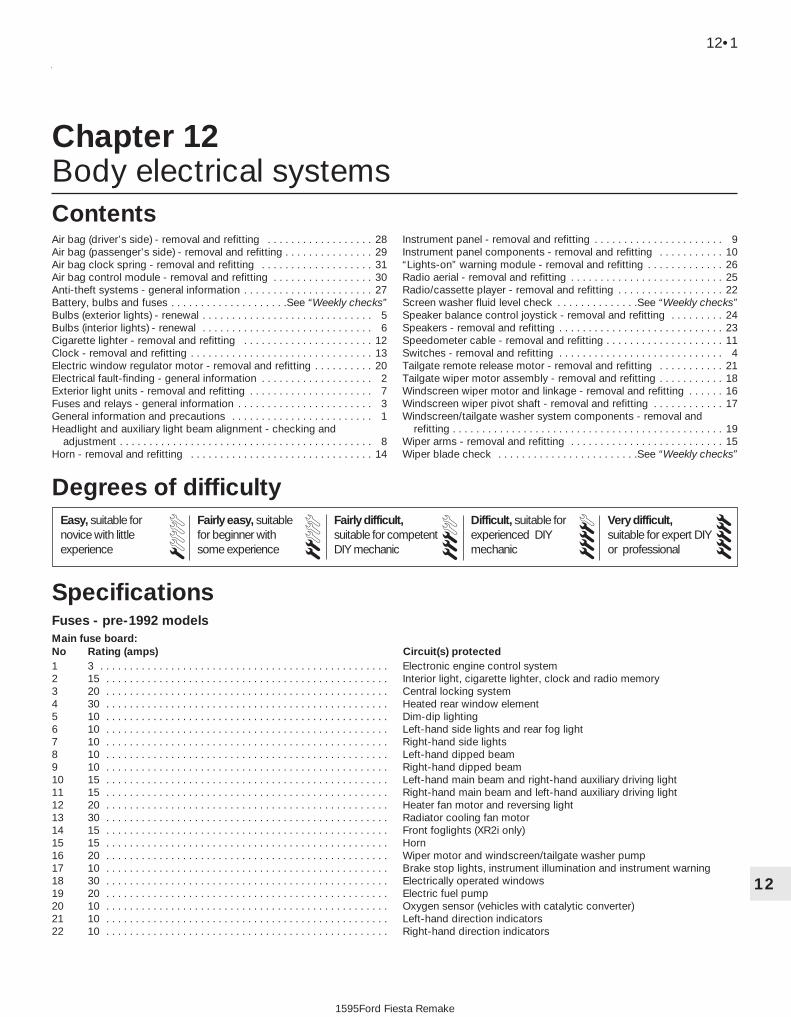
12
1595Ford Fiesta Remake
Fuses - pre-1992 modelsMain fuse board:No Rating (amps) Circuit(s) protected1 3 . . . . . . . . . . . . . . . . . . . . . . . . . . . . . . . . . . . . . . . . . . . . . . . . . Electronic engine control system2 15 . . . . . . . . . . . . . . . . . . . . . . . . . . . . . . . . . . . . . . . . . . . . . . . . Interior light, cigarette lighter, clock and radio memory3 20 . . . . . . . . . . . . . . . . . . . . . . . . . . . . . . . . . . . . . . . . . . . . . . . . Central locking system4 30 . . . . . . . . . . . . . . . . . . . . . . . . . . . . . . . . . . . . . . . . . . . . . . . . Heated rear window element5 10 . . . . . . . . . . . . . . . . . . . . . . . . . . . . . . . . . . . . . . . . . . . . . . . . Dim-dip lighting6 10 . . . . . . . . . . . . . . . . . . . . . . . . . . . . . . . . . . . . . . . . . . . . . . . . Left-hand side lights and rear fog light7 10 . . . . . . . . . . . . . . . . . . . . . . . . . . . . . . . . . . . . . . . . . . . . . . . . Right-hand side lights8 10 . . . . . . . . . . . . . . . . . . . . . . . . . . . . . . . . . . . . . . . . . . . . . . . . Left-hand dipped beam9 10 . . . . . . . . . . . . . . . . . . . . . . . . . . . . . . . . . . . . . . . . . . . . . . . . Right-hand dipped beam10 15 . . . . . . . . . . . . . . . . . . . . . . . . . . . . . . . . . . . . . . . . . . . . . . . . Left-hand main beam and right-hand auxiliary driving light11 15 . . . . . . . . . . . . . . . . . . . . . . . . . . . . . . . . . . . . . . . . . . . . . . . . Right-hand main beam and left-hand auxiliary driving light12 20 . . . . . . . . . . . . . . . . . . . . . . . . . . . . . . . . . . . . . . . . . . . . . . . . Heater fan motor and reversing light13 30 . . . . . . . . . . . . . . . . . . . . . . . . . . . . . . . . . . . . . . . . . . . . . . . . Radiator cooling fan motor14 15 . . . . . . . . . . . . . . . . . . . . . . . . . . . . . . . . . . . . . . . . . . . . . . . . Front foglights (XR2i only)15 15 . . . . . . . . . . . . . . . . . . . . . . . . . . . . . . . . . . . . . . . . . . . . . . . . Horn16 20 . . . . . . . . . . . . . . . . . . . . . . . . . . . . . . . . . . . . . . . . . . . . . . . . Wiper motor and windscreen/tailgate washer pump17 10 . . . . . . . . . . . . . . . . . . . . . . . . . . . . . . . . . . . . . . . . . . . . . . . . Brake stop lights, instrument illumination and instrument warning18 30 . . . . . . . . . . . . . . . . . . . . . . . . . . . . . . . . . . . . . . . . . . . . . . . . Electrically operated windows19 20 . . . . . . . . . . . . . . . . . . . . . . . . . . . . . . . . . . . . . . . . . . . . . . . . Electric fuel pump20 10 . . . . . . . . . . . . . . . . . . . . . . . . . . . . . . . . . . . . . . . . . . . . . . . . Oxygen sensor (vehicles with catalytic converter)21 10 . . . . . . . . . . . . . . . . . . . . . . . . . . . . . . . . . . . . . . . . . . . . . . . . Left-hand direction indicators22 10 . . . . . . . . . . . . . . . . . . . . . . . . . . . . . . . . . . . . . . . . . . . . . . . . Right-hand direction indicators
Chapter 12Body electrical systems
Air bag (driver’s side) - removal and refitting . . . . . . . . . . . . . . . . . . 28Air bag (passenger’s side) - removal and refitting . . . . . . . . . . . . . . . 29Air bag clock spring - removal and refitting . . . . . . . . . . . . . . . . . . . 31Air bag control module - removal and refitting . . . . . . . . . . . . . . . . . 30Anti-theft systems - general information . . . . . . . . . . . . . . . . . . . . . . 27Battery, bulbs and fuses . . . . . . . . . . . . . . . . . . . .See “Weekly checks”Bulbs (exterior lights) - renewal . . . . . . . . . . . . . . . . . . . . . . . . . . . . . 5Bulbs (interior lights) - renewal . . . . . . . . . . . . . . . . . . . . . . . . . . . . . 6Cigarette lighter - removal and refitting . . . . . . . . . . . . . . . . . . . . . . 12Clock - removal and refitting . . . . . . . . . . . . . . . . . . . . . . . . . . . . . . . 13Electric window regulator motor - removal and refitting . . . . . . . . . . 20Electrical fault-finding - general information . . . . . . . . . . . . . . . . . . . 2Exterior light units - removal and refitting . . . . . . . . . . . . . . . . . . . . . 7Fuses and relays - general information . . . . . . . . . . . . . . . . . . . . . . . 3General information and precautions . . . . . . . . . . . . . . . . . . . . . . . . 1Headlight and auxiliary light beam alignment - checking and
adjustment . . . . . . . . . . . . . . . . . . . . . . . . . . . . . . . . . . . . . . . . . . . 8Horn - removal and refitting . . . . . . . . . . . . . . . . . . . . . . . . . . . . . . . 14
Instrument panel - removal and refitting . . . . . . . . . . . . . . . . . . . . . . 9Instrument panel components - removal and refitting . . . . . . . . . . . 10“Lights-on” warning module - removal and refitting . . . . . . . . . . . . . 26Radio aerial - removal and refitting . . . . . . . . . . . . . . . . . . . . . . . . . . 25Radio/cassette player - removal and refitting . . . . . . . . . . . . . . . . . . 22Screen washer fluid level check . . . . . . . . . . . . . .See “Weekly checks”Speaker balance control joystick - removal and refitting . . . . . . . . . 24Speakers - removal and refitting . . . . . . . . . . . . . . . . . . . . . . . . . . . . 23Speedometer cable - removal and refitting . . . . . . . . . . . . . . . . . . . . 11Switches - removal and refitting . . . . . . . . . . . . . . . . . . . . . . . . . . . . 4Tailgate remote release motor - removal and refitting . . . . . . . . . . . 21Tailgate wiper motor assembly - removal and refitting . . . . . . . . . . . 18Windscreen wiper motor and linkage - removal and refitting . . . . . . 16Windscreen wiper pivot shaft - removal and refitting . . . . . . . . . . . . 17Windscreen/tailgate washer system components - removal and
refitting . . . . . . . . . . . . . . . . . . . . . . . . . . . . . . . . . . . . . . . . . . . . . . 19Wiper arms - removal and refitting . . . . . . . . . . . . . . . . . . . . . . . . . . 15Wiper blade check . . . . . . . . . . . . . . . . . . . . . . . .See “Weekly checks”
12•1
Specifications
Contents
Easy, suitable fornovice with littleexperience
Fairly easy, suitablefor beginner withsome experience
Fairly difficult,suitable for competentDIY mechanic
Difficult, suitable forexperienced DIYmechanic
Very difficult,suitable for expert DIYor professional
Degrees of difficulty
54321

Additional fuses behind main fuse board:
No Rating (amps) Circuit(s) protected23 - . . . . . . . . . . . . . . . . . . . . . . . . . . . . . . . . . . . . . . . . . . . . . . . . . Unused24/25 10 . . . . . . . . . . . . . . . . . . . . . . . . . . . . . . . . . . . . . . . . . . . . . . . . Rear fog lights26 15 . . . . . . . . . . . . . . . . . . . . . . . . . . . . . . . . . . . . . . . . . . . . . . . . Tailgate remote release27/28 30 . . . . . . . . . . . . . . . . . . . . . . . . . . . . . . . . . . . . . . . . . . . . . . . . Heated windscreen
Fuses - 1992 models onwardMain fuse board:Fuses 1 to 22 . . . . . . . . . . . . . . . . . . . . . . . . . . . . . . . . . . . . . . . . . . . . . Unchanged from pre-1992 modelsAdditional fuses behind main fuse board:No Rating (amps) Circuit(s) protected23* - . . . . . . . . . . . . . . . . . . . . . . . . . . . . . . . . . . . . . . . . . . . . . . . . . . Unused23** 10 . . . . . . . . . . . . . . . . . . . . . . . . . . . . . . . . . . . . . . . . . . . . . . . . Rear fog lights24* - . . . . . . . . . . . . . . . . . . . . . . . . . . . . . . . . . . . . . . . . . . . . . . . . . . Unused24** 10 . . . . . . . . . . . . . . . . . . . . . . . . . . . . . . . . . . . . . . . . . . . . . . . . Rear fog lights25 15 . . . . . . . . . . . . . . . . . . . . . . . . . . . . . . . . . . . . . . . . . . . . . . . . Tailgate remote release, anti-theft warning system26 30 . . . . . . . . . . . . . . . . . . . . . . . . . . . . . . . . . . . . . . . . . . . . . . . . Heated windscreen27 30 . . . . . . . . . . . . . . . . . . . . . . . . . . . . . . . . . . . . . . . . . . . . . . . . Heated windscreen28* 20 . . . . . . . . . . . . . . . . . . . . . . . . . . . . . . . . . . . . . . . . . . . . . . . . Full-length sunroof28** 30 . . . . . . . . . . . . . . . . . . . . . . . . . . . . . . . . . . . . . . . . . . . . . . . . Automatic transmission starter inhibitor29 10 . . . . . . . . . . . . . . . . . . . . . . . . . . . . . . . . . . . . . . . . . . . . . . . . Air bag* Pre-1994 models** 1994 models onward
Relays (pre-1992 models)Note: Relay locations and circuits controlled are liable to change from year to year. Consult a Ford dealer, for specific information.No Circuit(s) controlledI . . . . . . . . . . . . . . . . . . . . . . . . . . . . . . . . . . . . . . . . . . . . . . . . . . Heated rear windowII . . . . . . . . . . . . . . . . . . . . . . . . . . . . . . . . . . . . . . . . . . . . . . . . . . Windscreen wiper delayIII . . . . . . . . . . . . . . . . . . . . . . . . . . . . . . . . . . . . . . . . . . . . . . . . . . CFi (fuel injection) delay relayIV . . . . . . . . . . . . . . . . . . . . . . . . . . . . . . . . . . . . . . . . . . . . . . . . . . Not used on UK modelsV . . . . . . . . . . . . . . . . . . . . . . . . . . . . . . . . . . . . . . . . . . . . . . . . . . Ignition switchVI . . . . . . . . . . . . . . . . . . . . . . . . . . . . . . . . . . . . . . . . . . . . . . . . . . Automatic transmission starter inhibitor/electric fuel pump (bridge
fitted to carburettor engines without automatic transmission)VII . . . . . . . . . . . . . . . . . . . . . . . . . . . . . . . . . . . . . . . . . . . . . . . . . . Headlight main beamVIII . . . . . . . . . . . . . . . . . . . . . . . . . . . . . . . . . . . . . . . . . . . . . . . . . . Dim-dip lightingIX . . . . . . . . . . . . . . . . . . . . . . . . . . . . . . . . . . . . . . . . . . . . . . . . . . Not used on UK modelsX . . . . . . . . . . . . . . . . . . . . . . . . . . . . . . . . . . . . . . . . . . . . . . . . . . Not used on UK modelsXI . . . . . . . . . . . . . . . . . . . . . . . . . . . . . . . . . . . . . . . . . . . . . . . . . . Heated windscreenXII . . . . . . . . . . . . . . . . . . . . . . . . . . . . . . . . . . . . . . . . . . . . . . . . . . Anti-lock braking systemA . . . . . . . . . . . . . . . . . . . . . . . . . . . . . . . . . . . . . . . . . . . . . . . . . . Idle speed control (automatic transmission) two-tone horn (where fitted)B . . . . . . . . . . . . . . . . . . . . . . . . . . . . . . . . . . . . . . . . . . . . . . . . . . Not used on UK modelsC . . . . . . . . . . . . . . . . . . . . . . . . . . . . . . . . . . . . . . . . . . . . . . . . . . Front foglights (XR2i)D . . . . . . . . . . . . . . . . . . . . . . . . . . . . . . . . . . . . . . . . . . . . . . . . . . Headlight dipped beamE . . . . . . . . . . . . . . . . . . . . . . . . . . . . . . . . . . . . . . . . . . . . . . . . . . Dim-dip lighting
Relays (1992 models onward)Note: Relay locations and circuits controlled are liable to change from year to year. Consult a Ford dealer, for specific information.No Circuit(s) controlledI . . . . . . . . . . . . . . . . . . . . . . . . . . . . . . . . . . . . . . . . . . . . . . . . . . Heated rear windowII . . . . . . . . . . . . . . . . . . . . . . . . . . . . . . . . . . . . . . . . . . . . . . . . . . Windscreen wiper delayIII . . . . . . . . . . . . . . . . . . . . . . . . . . . . . . . . . . . . . . . . . . . . . . . . . . CFi delay relay or EFi supply relay (fuel injection)IV . . . . . . . . . . . . . . . . . . . . . . . . . . . . . . . . . . . . . . . . . . . . . . . . . . Not used on UK modelsV . . . . . . . . . . . . . . . . . . . . . . . . . . . . . . . . . . . . . . . . . . . . . . . . . . Ignition switchVI . . . . . . . . . . . . . . . . . . . . . . . . . . . . . . . . . . . . . . . . . . . . . . . . . . Automatic transmission starter inhibitor, anti-theft warning systemVII . . . . . . . . . . . . . . . . . . . . . . . . . . . . . . . . . . . . . . . . . . . . . . . . . . Headlight main beamVIII . . . . . . . . . . . . . . . . . . . . . . . . . . . . . . . . . . . . . . . . . . . . . . . . . . Anti-lock braking system and/or dim-dip lightingIX . . . . . . . . . . . . . . . . . . . . . . . . . . . . . . . . . . . . . . . . . . . . . . . . . . Not used on UK modelsX . . . . . . . . . . . . . . . . . . . . . . . . . . . . . . . . . . . . . . . . . . . . . . . . . . Not used on UK modelsXI . . . . . . . . . . . . . . . . . . . . . . . . . . . . . . . . . . . . . . . . . . . . . . . . . . Heated windscreenXII . . . . . . . . . . . . . . . . . . . . . . . . . . . . . . . . . . . . . . . . . . . . . . . . . . Anti-lock braking systemA . . . . . . . . . . . . . . . . . . . . . . . . . . . . . . . . . . . . . . . . . . . . . . . . . . Idle speed control (automatic transmission) or two-tone horn (where fitted)B . . . . . . . . . . . . . . . . . . . . . . . . . . . . . . . . . . . . . . . . . . . . . . . . . . Fuel pumpC . . . . . . . . . . . . . . . . . . . . . . . . . . . . . . . . . . . . . . . . . . . . . . . . . . Front foglights (XR2i, RS Turbo and RS 1800)D . . . . . . . . . . . . . . . . . . . . . . . . . . . . . . . . . . . . . . . . . . . . . . . . . . Headlight dipped beamE . . . . . . . . . . . . . . . . . . . . . . . . . . . . . . . . . . . . . . . . . . . . . . . . . . Dim-dip lightingF . . . . . . . . . . . . . . . . . . . . . . . . . . . . . . . . . . . . . . . . . . . . . . . . . . Not used on UK models
12•2 Body electrical systems
1595Ford Fiesta Remake

Bulbs WattageHeadlight (halogen) . . . . . . . . . . . . . . . . . . . . . . . . . . . . . . . . . . . . . . . . . H4, 60/55Sidelight (front) . . . . . . . . . . . . . . . . . . . . . . . . . . . . . . . . . . . . . . . . . . . . 5Direction indicators (main) . . . . . . . . . . . . . . . . . . . . . . . . . . . . . . . . . . . 21Side direction indicator repeaters . . . . . . . . . . . . . . . . . . . . . . . . . . . . . . 5Auxiliary driving and foglights (S and XR2i) . . . . . . . . . . . . . . . . . . . . . . H3, 55Stop/tail light . . . . . . . . . . . . . . . . . . . . . . . . . . . . . . . . . . . . . . . . . . . . . . 21/5Rear foglight . . . . . . . . . . . . . . . . . . . . . . . . . . . . . . . . . . . . . . . . . . . . . . 21Reversing light . . . . . . . . . . . . . . . . . . . . . . . . . . . . . . . . . . . . . . . . . . . . 21Number plate light . . . . . . . . . . . . . . . . . . . . . . . . . . . . . . . . . . . . . . . . . 10Interior light . . . . . . . . . . . . . . . . . . . . . . . . . . . . . . . . . . . . . . . . . . . . . . . 10Luggage compartment light . . . . . . . . . . . . . . . . . . . . . . . . . . . . . . . . . . 5Instrument warning lights . . . . . . . . . . . . . . . . . . . . . . . . . . . . . . . . . . . . 1.3 or 2.6Panel illumination . . . . . . . . . . . . . . . . . . . . . . . . . . . . . . . . . . . . . . . . . . 1.3 or 2.6Cigarette lighter illumination . . . . . . . . . . . . . . . . . . . . . . . . . . . . . . . . . . 1.4Automatic transmission selector illumination . . . . . . . . . . . . . . . . . . . . . 2
LubricantsGrease for windscreen wiper linkage and pivots . . . . . . . . . . . . . . . . . . To Ford specification SAM-1C-911-A
Torque wrench settings Nm lbf ftWiper motor to bracket . . . . . . . . . . . . . . . . . . . . . . . . . . . . . . . . . . . . . . 8 to 9 6 to 7Wiper motor bracket to bulkhead/tailgate . . . . . . . . . . . . . . . . . . . . . . . 6 to 8 4 to 6Windscreen wiper crank to driving shaft nut . . . . . . . . . . . . . . . . . . . . . 22 to 24 16 to 18Windscreen/tailgate wiper arm retaining nut . . . . . . . . . . . . . . . . . . . . . 17 to 18 12 to 13Windscreen wiper pivot shaft nut . . . . . . . . . . . . . . . . . . . . . . . . . . . . . . 9 to 12 7 to 9Windscreen/tailgate washer reservoir securing bolts . . . . . . . . . . . . . . . 2.5 to 3.5 2 to 3Headlight retaining bolt . . . . . . . . . . . . . . . . . . . . . . . . . . . . . . . . . . . . . 5.4 to 7.0 4 to 5Tail light securing nuts . . . . . . . . . . . . . . . . . . . . . . . . . . . . . . . . . . . . . . 1.5 to 2.5 1 to 2Auxiliary light retaining nut (S models) . . . . . . . . . . . . . . . . . . . . . . . . . . 6.8 to 9.2 5 to 7Horn bracket retaining bolt . . . . . . . . . . . . . . . . . . . . . . . . . . . . . . . . . . . 24 to 33 18 to 24Starter inhibitor switch . . . . . . . . . . . . . . . . . . . . . . . . . . . . . . . . . . . . . . 9 to 14 7 to 10
Body electrical systems 12•3
12
1595Ford Fiesta Remake
1 General information andprecautions
General informationThe electrical system is of 12-volt negative
earth type. Power for the lights and allelectrical accessories is supplied by alead/acid battery, which is charged by theengine-driven alternator.
This Chapter covers repair and serviceprocedures for the various electricalcomponents not associated with the engine.Information on the battery, ignition system,alternator, and starter motor can be found inChapter 5A and B.
All models from 1994 onwards are fittedwith a driver’s air bag, which is designed toprevent serious chest and head injuries to thedriver during an accident. A similar bag for thefront seat passenger is also available. Thecombined sensor and electronics for the airbag is located next to the steering columninside the vehicle, and contains a back-upcapacitor, crash sensor, decelerometer,safety sensor, integrated circuit andmicroprocessor. The air bag is inflated by agas generator, which forces the bag out of the
module cover in the centre of the steeringwheel. A “clock spring” ensures that a goodelectrical connection is maintained with the airbag at all times - as the steering wheel isturned in each direction, the spring winds andunwinds.
An anti-theft alarm system is available onlater models, and is triggered if the vehicle isbroken into through the doors, bonnet, ortailgate. The alarm will also be triggered if theignition or audio equipment is tampered with.Additionally, from the 1994 model yearonwards, a Passive Anti-Theft System (PATS)is fitted. This system, (which worksindependently of the standard alarm) preventsthe engine from being started unless aspecific code, programmed into the ignitionkey, is recognised by the PATS transceiver.
PrecautionsWarning: Before carrying outany work on the electricalsystem, read through theprecautions given in “Safety
first!” at the beginning of this manual andin Chapter 5A, Section 1.Caution: Prior to working on anycomponent in the electrical system, thebattery negative lead should first bedisconnected, to prevent the possibility of
electrical short-circuits and/or fires. If aradio/cassette player with anti-theftsecurity code is fitted, refer to theinformation given in the reference sectionsof this manual before disconnecting thebattery.
2 Electrical fault-finding -general information 2
Note: Refer to the precautions given in“Safety first!” and in Section 1 of this Chapterbefore starting work. The following tests relateto testing of the main electrical circuits, andshould not be used to test delicate electroniccircuits (such as engine managementsystems), particularly where an electroniccontrol unit is used. Also refer to theprecautions given in Chapter 5A, Section 1.
General1 A typical electrical circuit consists of anelectrical component, any switches, relays,motors, fuses, fusible links or circuit breakersrelated to that component, and the wiring andconnectors which link the component to boththe battery and the chassis. To help topinpoint a problem in an electrical circuit,

wiring diagrams are included at the end of thismanual.2 Before attempting to diagnose an electricalfault, first study the appropriate wiringdiagram, to obtain a complete understandingof the components included in the particularcircuit concerned. The possible sources of afault can be narrowed down by noting if othercomponents related to the circuit areoperating properly. If several components orcircuits fail at one time, the problem is likely tobe related to a shared fuse or earthconnection.3 Electrical problems usually stem fromsimple causes, such as loose or corrodedconnections, a faulty earth connection, ablown fuse, a melted fusible link, or a faultyrelay (refer to Section 3 for details of testingrelays). Visually inspect the condition of allfuses, wires and connections in a problemcircuit before testing the components. Usethe wiring diagrams to determine whichterminal connections will need to be checkedin order to pinpoint the trouble-spot.4 The basic tools required for electrical fault-finding include a circuit tester or voltmeter (a12-volt bulb with a set of test leads can alsobe used for certain tests); an ohmmeter (tomeasure resistance and check for continuity);a battery and set of test leads; and a jumperwire, preferably with a circuit breaker or fuseincorporated, which can be used to bypasssuspect wires or electrical components.Before attempting to locate a problem withtest instruments, use the wiring diagram todetermine where to make the connections.
Warning: Under nocircumstances may livemeasuring instruments such asohmmeters, voltmeters or a bulb
and test leads be used to test any of theair bag circuitry or components. Anytesting in these areas must be left to aFord dealer as there is a danger ofactivating the system if the correctprocedures are not followed.
5 To find the source of an intermittent wiringfault (usually due to a poor or dirtyconnection, or damaged wiring insulation), a“wiggle” test can be performed on the wiring.This involves wiggling the wiring by hand tosee if the fault occurs as the wiring is moved.It should be possible to narrow down thesource of the fault to a particular section ofwiring. This method of testing can be used inconjunction with any of the tests described inthe following sub-Sections.6 Apart from problems due to poorconnections, two basic types of fault canoccur in an electrical circuit - open-circuit, orshort-circuit.7 Open-circuit faults are caused by a breaksomewhere in the circuit, which preventscurrent from flowing. An open-circuit fault willprevent a component from working.8 Short-circuit faults are caused by a “short”somewhere in the circuit, which allows the
current flowing in the circuit to “escape” alongan alternative route, usually to earth. Short-circuit faults are normally caused by abreakdown in wiring insulation, which allows afeed wire to touch either another wire, or anearthed component such as the bodyshell. Ashort-circuit fault will normally cause therelevant circuit fuse to blow.
Finding an open-circuit9 To check for an open-circuit, connect onelead of a circuit tester or the negative lead of avoltmeter either to the battery negativeterminal or to a known good earth.10 Connect the other lead to a connector inthe circuit being tested, preferably nearest tothe battery or fuse. At this point, batteryvoltage should be present, unless the leadfrom the battery or the fuse itself is faulty(bearing in mind that some circuits are liveonly when the ignition switch is moved to aparticular position).11 Switch on the circuit, then connect thetester lead to the connector nearest the circuitswitch on the component side.12 If voltage is present (indicated either bythe tester bulb lighting or a voltmeter reading,as applicable), this means that the section ofthe circuit between the relevant connectorand the switch is problem-free.13 Continue to check the remainder of thecircuit in the same fashion.14 When a point is reached at which novoltage is present, the problem must liebetween that point and the previous test pointwith voltage. Most problems can be traced toa broken, corroded or loose connection.
Finding a short-circuit15 To check for a short-circuit, firstdisconnect the load(s) from the circuit (loadsare the components which draw current froma circuit, such as bulbs, motors, heatingelements, etc).16 Remove the relevant fuse from the circuit,and connect a circuit tester or voltmeter to thefuse connections.17 Switch on the circuit, bearing in mind thatsome circuits are live only when the ignitionswitch is moved to a particular position.18 If voltage is present (indicated either bythe tester bulb lighting or a voltmeter reading,as applicable), this means that there is ashort-circuit.19 If no voltage is present during this test,but the fuse still blows with the load(s)reconnected, this indicates an internal fault inthe load(s).
Finding an earth fault20 The battery negative terminal isconnected to “earth” - the metal of theengine/transmission and the vehicle body -and many systems are wired so that they onlyreceive a positive feed, the current returningvia the metal of the car body. This means thatthe component mounting and the body formpart of that circuit. Loose or corroded
mountings can therefore cause a range ofelectrical faults, ranging from total failure of acircuit, to a puzzling partial failure. Inparticular, lights may shine dimly (especiallywhen another circuit sharing the same earthpoint is in operation), motors (eg wipermotors or the radiator cooling fan motor) mayrun slowly, and the operation of one circuitmay have an apparently-unrelated effect onanother. Note that on many vehicles, earthstraps are used between certaincomponents, such as the engine/transmission and the body, usually wherethere is no metal-to-metal contact betweencomponents, due to flexible rubbermountings, etc.21 To check whether a component isproperly earthed, disconnect the battery (referto Chapter 5A, Section 1) and connect onelead of an ohmmeter to a known good earthpoint. Connect the other lead to the wire orearth connection being tested. The resistancereading should be zero; if not, check theconnection as follows.22 If an earth connection is thought to befaulty, dismantle the connection, and cleanboth the bodyshell and the wire terminal (orthe component earth connection matingsurface) back to bare metal. Be careful toremove all traces of dirt and corrosion, thenuse a knife to trim away any paint, so that aclean metal-to-metal joint is made. Onreassembly, tighten the joint fastenerssecurely; if a wire terminal is being refitted,use serrated washers between the terminaland the bodyshell, to ensure a clean andsecure connection. When the connection isremade, prevent the onset of corrosion in thefuture by applying a coat of petroleum jelly orsilicone-based grease, or by spraying on (atregular intervals) a proprietary ignition sealeror a water-dispersant lubricant.
3 Fuses and relays - general information
Note: It is important to note that the ignitionswitch and the appropriate electrical circuitmust always be switched off before any of thefuses (or relays) are removed and renewed.1 The main fuse and relay board is locatedbelow the facia panel to the right of thesteering wheel. The fuses can be inspectedand if necessary renewed, by removing thehinged access cover. The remainingadditional fuses and relays (depending onmodel) may be accessed by removing the twofuse board retaining screws, releasing theretaining lugs on either side of the main fuseplate and withdrawing the fuse/relay boarddownwards into the driver’s footwell. Eachfuse location is numbered - refer to the fusechart in the Specifications at the start of thisChapter to check which circuits are protectedby each fuse. Plastic tweezers are attached to
12•4 Body electrical systems
1595Ford Fiesta Remake
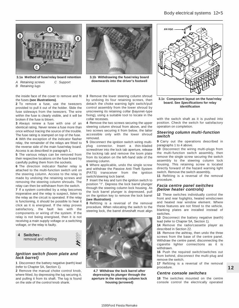
the inside face of the cover to remove and fitthe fuses (see illustrations).2 To remove a fuse, use the tweezersprovided to pull it out of the holder. Slide thefuse sideways from the tweezers. The wirewithin the fuse is clearly visible, and it will bebroken if the fuse is blown.3 Always renew a fuse with one of anidentical rating. Never renew a fuse more thanonce without tracing the source of the trouble.The fuse rating is stamped on top of the fuse.4 With the exception of the indicator flasherrelay, the remainder of the relays are fitted tothe reverse side of the main fuse/relay board.Access is as described in paragraph 1.5 The various relays can be removed fromtheir respective locations on the fuse board bycarefully pulling them from the sockets.6 The direction indicator flasher relay isattached to the multi-function switch unit onthe steering column. Access to the relay ismade by undoing the retaining screws andremoving the steering column shrouds. Therelay can then be withdrawn from the switch.7 If a system controlled by a relay becomesinoperative and the relay is suspect, listen tothe relay as the circuit is operated. If the relayis functioning, it should be possible to hear itclick as it is energised. If the relay provessatisfactory, the fault lies with thecomponents or wiring of the system. If therelay is not being energised, then it is notreceiving a main supply voltage or a switchingvoltage, or the relay is faulty.
4 Switches - removal and refitting 2
Ignition switch (loom plate andlock barrel)1 Disconnect the battery negative (earth) lead(refer to Chapter 5A, Section 1).2 Remove the manual choke control knob,where fitted, by depressing the lug securing it,and pulling it from its shaft. The lug is foundon the side of the control knob shank.
3 Remove the lower steering column shroudby undoing its four retaining screws, thendetach the choke warning light switch/pullcontrol assembly from the lower shroud byunscrewing its retaining collar (bayonet-typefixing), using a suitable tool to locate in thecollar recesses.4 Remove the two screws securing the uppersteering column shroud from above, and thetwo screws securing it from below, the latteraccessible only with the lower shroudremoved.5 Disconnect the ignition switch wiring multi-plug connector. Insert a thin-bladedscrewdriver into the lock tab aperture, releasethe locking tab and remove the loom platefrom its location on the left-hand side of thesteering column.6 Where applicable, undo the single screwand withdraw the Passive Anti-Theft System(PATS) transceiver from the ignitionswitch/steering lock barrel.7 Insert the key and turn the ignition switch toposition ”I”. Depress the lock barrel plungerthrough the steering column lock housing. Asthe lock barrel plunger is depressed, pull on the ignition key to remove the lock barrel(see illustration).8 Refitting is a reversal of the removalprocedure. When relocating the switch to thesteering lock, the barrel driveshaft must align
with the switch shaft as it is pushed intoposition. Check the switch for satisfactoryoperation on completion.
Steering column multi-functionswitch9 Carry out the operations described inparagraphs 1 to 4 above.10 Disconnect the wiring multi-plugs fromthe multi-function switch assembly, thenremove the single screw securing the switchassembly to the steering column lockhousing. This retaining screw is locateddirectly forward of the hazard warning lightswitch. Remove the switch assembly.11 Refitting is a reversal of the removalprocedure.
Facia centre panel switches(below heater controls)12 These switches individually control thefront and rear foglights, heated windscreenand heated rear window element. Wherethese features are not fitted to the vehicle,blanking plates are installed instead ofswitches.13 Disconnect the battery negative (earth)lead (refer to Chapter 5A, Section 1).14 Remove the radio/cassette player asdescribed in Section 22.15 Remove the ashtray, then undo the threescrews from the base of the centre panel.Withdraw the centre panel, disconnecting thecigarette lighter connections as it iswithdrawn.16 Push the required switch/switches outfrom behind, disconnect the multi-plug andremove the switch.17 Refitting is a reversal of the removalprocedure.
Centre console switches18 The switches mounted on the centreconsole control the electrically operated
Body electrical systems 12•5
3.1c Component layout on the fuse/relayboard. See Specifications for relay
identification
3.1b Withdrawing the fuse/relay boarddownwards into the driver’s footwell
3.1a Method of fuse/relay board retention
A Retaining screws C SupportB Retaining lugs
4.7 Withdraw the lock barrel afterdepressing its plunger through the
aperture in the steering column lockhousing (arrowed)
12
1595Ford Fiesta Remake

windows (early models) and the tailgateremote release mechanism, where fitted.19 Disconnect the battery negative (earth)lead (refer to Chapter 5A, Section 1).20 To remove a switch, carefully prise it fromits location using a thin flat-bladedscrewdriver, then disconnect the multi-plug(see illustrations).21 To refit, connect the multi-plug then pushhome to secure.
Heater fan motor control switch22 Disconnect the battery negative (earth)lead (refer to Chapter 5A, Section 1).23 Pull the heater fan motor control knob off,then move the air distribution andtemperature controls fully to the right. Unclipand remove the heater slide facia towards theleft-hand side of the vehicle, removing theslide control knobs only as necessary, anddisconnecting its bulbholder (bayonet type) asit is withdrawn (see illustration).24 Squeeze the two release tabs together onthe heater fan motor control switch, andremove it, disconnecting its multi-plug as it iswithdrawn.25 Refit by reversing the removal procedure.
Brake stop-light switch26 The brake stop-light switch is attached tothe brake pedal mounting bracket.27 Detach the wiring multi-plug from theswitch, then twist the switch through a quarterof a turn (90º) anticlockwise and withdraw itfrom the bracket.
28 Insert the switch into its retainer, press itlightly against the brake pedal until all freeplay is just taken up, then turn the switchclockwise to secure. Reconnect the switchwiring connector and the battery.
Handbrake warning light switch29 Push the carpet mounding down asnecessary to gain access to the switch,located on the handbrake lever.30 Remove the cover, then disconnect thewarning light switch wiring multi-plug (seeillustration). Undo the two screws securingthe switch to the handbrake lever assemblyand remove the switch.31 Refit by reversing the removal procedure.
Low brake fluid level warninglight switch32 This is incorporated into the brake fluidreservoir cap, and senses fluid level in thereservoir. It cannot be renewed separatelyfrom the cap.33 To remove, disconnect the warningindicator loom multi-plug and unscrew thereservoir cap.34 Refit by reversing the removal procedure.
Courtesy light switches35 Disconnect the battery negative (earth)lead (refer to Chapter 5A, Section 1).36 With the door open, undo the retainingscrew and withdraw the switch from the doorpillar. Pull out the wiring slightly, and tie a
piece of string to it, so that it can be retrievedif it drops down into the door pillar.37 Disconnect the wiring from the switch.38 Refitting is a reversal of removal.
Reversing light switch39 Refer to Chapter 7A, Section 6.
Starter inhibitor switch(automatic transmission)40 Disconnect the battery negative (earth)lead (refer to Chapter 5A, Section 1).41 The starter inhibitor switch is located onthe transmission housing, and prevents theengine from being started with the selectorlever in any position except “P” or “N”.Access to the switch is gained after raisingand supporting the vehicle at the front end onaxle stands (see “Jacking and vehiclesupport”).42 Detach the switch multi-plug, thenunscrew and remove the switch from thetransmission, together with its O-ring. As theswitch is removed, catch any fluid spillage in asuitable container, and plug the switchaperture in the transmission to prevent anyfurther loss.43 Refitting is a reversal of the removalprocedure. Use a new O-ring, and tighten theswitch securely. Ensure that the wiringconnection is securely made. On completion,check and if necessary top-up the automatictransmission fluid (see Chapter 1) then checkthat the engine only starts when the selectoris in the “P” or “N” position.
Luggage area contact plate44 Disconnect the battery negative (earth)lead (refer to Chapter 5A, Section 1).45 Open the tailgate and release the contactplate side retaining clips using a thin-bladedscrewdriver. Push the contact plate from itslocation in the body.46 Disconnect the wiring multi-plug andremove the plate (see illustration).47 Refit in the reverse order of removal.
Luggage area contact switch48 Disconnect the battery negative (earth)lead (refer to Chapter 5A, Section 1).49 Open the tailgate and remove its innertrim panel (see Chapter 11).
12•6 Body electrical systems
4.46 Withdrawing the luggage areacontact plate for access to disconnect the
multi-plug
4.30 Removing the cover from thehandbrake warning light switch
4.23 Heater fan motor control switchremoval
4.20b . . . then disconnect its multiplugand remove the switch
4.20a Prise the centre console switch upfrom its location . . .
1595Ford Fiesta Remake

50 Undo the two screws securing the contactswitch and withdraw it from its tailgatelocation.51 Unclip and disconnect the switch multi-plug, and disconnect the earth wiring.Remove the switch.52 Refit in the reverse order of removal.Make sure that the pins and their contacts areclean. On completion, check the operation ofthe rear wipers, courtesy light, heated rearwindow and the tailgate release/centrallocking system.
Electric window switches (1992 models onward)53 On later models the electric windowswitches are located in the upper surfaces ofthe door stowage pockets. Removal andrefitting is the same as for the earlier centreconsole mounted switches describedpreviously in this Section.
5 Bulbs (exterior lights) -renewal 1
Note: Ensure that all exterior lights areswitched off before disconnecting the wiringconnectors to any exterior light bulbs. Notethat if a bulb fails, and has just been in use, itwill still be extremely hot, particularly in thecase of a headlight bulb.
Headlight1 From within the engine compartment,disconnect the multi-plug from the back of theheadlight.2 Remove the rubber bulb protective cap,then unlock the bulb retaining spring clip orretaining ring (according to type) andwithdraw the bulb (see illustrations).
Caution: Take care not to touch the bulbglass with your fingers - if accidentallytouched, clean the bulb with methylatedspirit.
3 Refitting is a reversal of the removalprocedure.
Front sidelight4 The bulbholder is located on the side of theheadlight unit, and is removed by twistinganti-clockwise and withdrawing from withinthe engine compartment.5 Withdraw the push-fit bulb from its holder.6 Refitting is a reversal of the removalprocedure.
Front direction indicator7 Remove the direction indicator light unit byreleasing the retaining spring from its bodylocation, then pulling the light assemblyforwards. Disconnect its multi-plug as it iswithdrawn.8 Turn the bulbholder anti-clockwise andremove it (see illustration). The bulb is abayonet type fitting in its holder.9 Refitting is a reversal of the removalprocedure.
Front direction indicator siderepeater10 Remove the appropriate front wheel archliner as described in Chapter 11.11 Remove the appropriate sill scuff plate asdescribed in Chapter 11, and release the clipsecuring the insulation to the panel forward ofthe lower A-pillar.12 Disconnect the supply lead connector and
the earth lead, then release their grommetfrom its panel location.13 From outside the vehicle, twist the lightassembly to release it, then withdraw it and itsleads (see illustration).14 Refitting is a reversal of the removalprocedure, ensuring that the grommet isseated correctly in its panel location.
Auxiliary lights
S models15 Undo the screw at the base of the light,then withdraw the lens and reflector assemblyfrom the light housing.16 Disconnect the wiring then release thebulb retainer and remove the bulb.17 Refitting is a reversal of the removalprocedure.
XR2i models18 Remove the auxiliary light assembly fromits bumper location, as described in Section 7.19 Release the bulb retainer, then remove thebulb (see illustration).20 Refitting is a reversal of the removalprocedure.
Rear light cluster (all modelsexcept Courier)21 Access to the rear light cluster bulbholderis gained from the luggage compartment.Disconnect the multi-plug from thebulbholder, then press the retaining lugs on
Body electrical systems 12•7
5.2b . . . then unlock the headlight bulbretaining spring and withdraw the bulb
5.2a Remove the protective cap . . .
5.19 Releasing the auxiliary light bulbretainer (XR2i models)
5.13 Removing the direction indicator siderepeater bulbholder assembly
5.8 Remove the front direction indicatorlight bulbholder by turning it anti-
clockwise
A Light unit C Multi-plugB Bulbholder D Retaining spring
12
1595Ford Fiesta Remake

the bulbholder together and remove it (seeillustrations).22 All bulbs are of bayonet type fitting.23 Refitting is a reversal of the removalprocedure.
Rear light cluster (Couriermodels)24 Working inside the load compartment,unscrew the two black plastic nuts securingthe light cluster assembly. Withdraw theassembly to the outside of the vehicle,disconnecting the wiring from the bulbholder(see illustrations).25 All bulbs are of bayonet type fitting.26 Refitting is a reversal of the removalprocedure.
Number plate lights27 Insert a thin flat-bladed screwdriverbetween the light assembly and the bumper,and carefully prise the light out. Use a rag, ora piece of card, between the screwdriver andthe bumper, to prevent damage to thebumper.28 Detach the connections on the undersideof the light assembly.29 Release the tab securing the light cover tothe bulbholder, and remove the cover (seeillustration).30 The bulb is a bayonet type fitting in itsholder.31 Refitting is a reversal of the removalprocedure.
6 Bulbs (interior lights) -renewal 2
Instrument panel illuminationand warning lights1 Refer to Section 10.
Automatic transmission selectorillumination2 Using a thin flat-bladed screwdriver, priseup the selector cover and remove it.3 Pull the bulb assembly to release it from theselector lever, then remove its cover. The bulbis a bayonet fit in its holder (see illustrations).4 Refitting is a reversal of the removalprocedure.
Hazard warning switch5 The hazard warning light switch, an integralpart of the steering column multi-functionswitch assembly, has a bulb cover which pullsoff. The bulb is removed by pulling it from itslocation.6 Refitting is a reversal of the removalprocedure.
Clock illumination7 Carefully prise the clock out of its facialocation, as described in Section 13.8 Twist the bulbholder and withdraw it fromthe rear of the clock (see illustration). Note
12•8 Body electrical systems
6.8 Withdrawing the clock illuminationbulb and its integral holder from the rear of
the clock
6.3b . . . followed by the (bayonet fitting)bulb
6.3a Remove the selector illumination bulbcover . . .
5.29 Release the number plate lightsecuring tab (arrowed) and separate the
bulbholder and light cover
5.24b . . . then withdraw the assembly tothe outside of the vehicle
5.24a On Courier models, unscrew the twoblack plastic nuts securing the rear light
cluster assembly . . .
5.21b . . . then having pressed its retaininglugs, withdraw the bulbholder for access
to the bulbs
5.21a Disconnect the ear light clustermulti-plug from the bulbholder . . .
1595Ford Fiesta Remake

that the bulb and bulbholder cannot beseparated - they are replaced as an assembly.9 Refitting is a reversal of the removalprocedure.
Cigarette lighter illumination10 Remove the cigarette lighter, as describedin Section 12.11 Pull the bulbholder from its location in theilluminated surround, then pull the bulb out ofthe bulbholder.12 Refitting is a reversal of the removalprocedure.
Heater facia illumination13 Pull the heater fan motor control knob off,then move the air distribution andtemperature controls fully to the right. Unclipand remove the heater slide facia towards theleft-hand side of the vehicle, removing theslide control knobs only as necessary, anddisconnecting its bulbholder (bayonet type) asit is withdrawn (see illustration).14 The bulb is removed by pulling it from itsbulbholder.15 Refitting is a reversal of the removalprocedure.
Interior (courtesy) light16 Insert a thin flat-bladed screwdriver intothe slot in the light assembly, and carefullylever it out of its aperture. The bulb is abayonet fit (see illustrations).17 Refit the bulb by reversing the method of
removal, then insert the switch end of the lightto the aperture, pivot the light upwards andpush home to secure.
Luggage compartment(courtesy) light18 Carefully prise the luggage compartment(courtesy) light assembly out of its location,using a thin flat-bladed screwdriver. Twist thebulbholder anti-clockwise to remove.19 The bulb is removed by pulling it from itsbulbholder.20 Refitting is a reversal of the removalprocedure.
7 Exterior light units - removal and refitting 2
1 Disconnect the battery negative (earth) lead(refer to Chapter 5A, Section 1), beforeremoving any of the light units.
Headlight2 Disconnect the multi-plug from the back ofthe headlights (see illustration).3 Twist the sidelight bulb holder to release,then withdraw it.4 Remove the headlight securing bolt anddepress the headlight retaining spring, toallow the headlight assembly to be hinged
forwards and out of its location (seeillustration).5 Refitting is a reversal of the removalprocedure, ensuring that the lower headlightmounting guide is inserted correctly, and thatthe retaining spring engages fully (seeillustration).6 On completion, check the headlight beamalignment as described in Section 8.
Front direction indicator7 To remove, release the indicator lightretaining spring from its body location, thenpull the light assembly forwards anddisconnect its multi-plug as it is withdrawn(see illustrations).
Body electrical systems 12•9
6.16b Interior (courtesy) light pivoted foraccess to the bulb
7.2 Disconnecting the multi-plug from theback of the headlight
6.16a Releasing the interior (courtesy)light from its location
6.13 Heater fan illumination arrangement
7.7a Release the front direction indicatorlight retaining spring from its body
location . . .
7.5 Refitting the headlight. Mountingguides (A) to fit to panel (B)
7.4 Headlight retaining bolt (A), andretaining spring arrangement (B)
12
1595Ford Fiesta Remake

8 Refitting is a reversal of the removalprocedure.
Front direction indicator siderepeater9 Remove the appropriate front wheel archliner as described in Chapter 11.10 Remove the appropriate sill scuff plate asdescribed in Chapter 11, and release the clipsecuring the insulation to the panel forward ofthe lower A-pillar.11 Disconnect the supply lead connector andthe earth lead, then release their grommetfrom its panel location.12 From outside the vehicle, twist the lightassembly to release it, then withdraw it and itsleads.13 Refitting is a reversal of the removalprocedure, ensuring that the grommet isseated correctly in its panel location.
Rear light cluster14 Disconnect the multi-plug from thebulbholder, then press the retaining lugs onthe bulbholder together and remove it (seeillustration).
15 Unscrew the four nuts securing the lightunit, then remove the unit and its seal.16 Refitting is a reversal of the removalprocedure. Tighten the light unit securing nutsto their specified torque.
Number plate light17 Insert a thin flat-bladed screwdriverbetween the light assembly and the bumper,and carefully prise the light out. Use a rag, ora piece of card, between the screwdriver andthe bumper, to prevent damage to thebumper.18 Detach the connections on the undersideof the light assembly.19 Refitting is a reversal of the removalprocedure.
Auxiliary lights
S models20 Disconnect the battery negative (earth)lead (refer to Chapter 5A, Section 1).21 Disconnect the light wiring multi-plug thenunscrew its retaining nut, withdraw the boltand remove the light unit (see illustration).
22 Refitting is a reversal of the removalprocedure, tightening the retaining nut to thespecified torque. On completion, check theauxiliary light beam alignment as described inSection 8.
XR2i models23 Disconnect the battery negative (earth)lead (refer to Chapter 5A, Section 1).24 Undo the four Torx retaining screwssecuring the relevant dual light assembly to itsbumper location. Note that the retaining andadjusting screws are captive within the lightassembly - they cannot be removed from the assembly (see illustration).25 Withdraw the light assembly from itslocation, then remove the caps protecting thebulbs and disconnect the wiring.26 If required, the lights may be removedindividually from their housing at this stage.Each light is secured to its housing unit by acombination of two types of clips - foglightretention differs from driving light retention.27 The adjusting/retaining clips are removedby undoing the adjustment screws on thefront of the housing unit, then turning the clipsusing pliers or similar tool, beforewithdrawing. To remove a retaining-only clip,lift the lug on the side of the clip using ascrewdriver, then turn the clip using pliers orsimilar tool, before withdrawing.28 Refitting is a reversal of the removalprocedure. On completion, check the auxiliarylight beam alignment as described in Section 8.
8 Headlight and auxiliary lightbeam alignment - checkingand adjustment
21 Accurate adjustment of the headlight andauxiliary light beams is only possible usingoptical beam-setting equipment, and this
12•10 Body electrical systems
7.24 Auxiliary light assembly (XR2i models) - left-hand unit shown
A Light assembly retainingscrews
B Fog light vertical adjustmentscrew
C Driving light vertical adjustmentscrew
D Driving light horizontaladjustment screw
E Bulb protective capsF Fog light bulb connectorG Bulb earth leadsH Driving light bulb connector
7.21 Auxiliary light fixture (S models)
A Bracket retaining nuts C Auxiliary light multi-plugB Auxiliary light retaining nut
7.14 Press the retaining lugs on the rearlight cluster bulbholder together (broken
arrows) to release the bulbholder
7.7b . . . then pull the light unit out toenable the multi-plug (arrowed) to be
disconnected
1595Ford Fiesta Remake

work should therefore be carried out by aFord dealer or service station with thenecessary facilities.2 Temporary adjustment can be made whenthe headlight has been removed and refitted,or to compensate for normal adjustmentwhenever a heavy load is being carried. Turnthe adjustment screws at the rear of theheadlight unit to make the adjustment (seeillustration).3 Before making any adjustments to theheadlight settings, it is important that the tyrepressures are correct, and that the vehicle isstanding on level ground. Bounce the front ofthe vehicle a few times to settle thesuspension. Ideally, somebody of normal sizeshould sit in the driver’s seat during theadjustment, and the vehicle should have a fulltank of fuel.4 S model auxiliary lights are adjusted byslackening the light retaining nuts andswivelling the light assemblies (seeillustration 7.21). Tighten the nuts uponcompletion.5 XR2i model auxiliary lights are individuallyadjustable within their housings, provisionbeing made for both vertical and horizontaladjustment of the driving lights, and vertical
adjustment only of the foglights. Adjustment ismade via Torx-head captive screws on thefront of the housings (see illustration 7.24).6 Whenever temporary adjustments aremade, the settings must be reset as soon aspossible once the vehicle is in normal use.
9 Instrument panel - removal and refitting 2
Removal1 Disconnect the battery negative (earth) lead(refer to Chapter 5A, Section 1).2 Disconnect the speedometer cable at thetransmission casing (see Section 11).3 Remove the two screws securing theinstrument panel bezel from its underside.Remove the bezel.4 Remove the four screws securing theinstrument panel to its location, then carefullypull it out to allow access to the speedometercable and multi-plug connections. Disconnectthe speedometer cable and multi-plug, thenremove the instrument panel from the vehicle(see illustrations).
Refitting5 Refitting is a reversal of removal. Oncompletion check the function of all electricalcomponents.
10 Instrument panelcomponents - removal and refitting 1
Removal1 Remove the instrument panel as describedin Section 9.
Panel illumination and warning lightbulbs2 All bulbholders are a bayonet fit, requiring a“twist and withdraw” removal technique (seeillustration). Bulbs cannot be removed fromtheir holders -they are renewed complete.
Printed circuit3 Insert a thin flat-bladed screwdriver into themulti-plug retainer and carefully unclip it,having noted its orientation (see illustration).4 Remove all panel illumination and warninglight bulbholders.5 Using a suitable tool (a trim clip removaltool is ideal), carefully prise the printed circuitoff its instrument terminals, and release it fromits retainers before removing.
Speedometer6 Remove the two bulbholders on the top ofthe panel assembly, and release their strip ofprinted circuit from its retainers, so that theinstrument panel halves may be separated.7 Separate the panel halves by releasing the
Body electrical systems 12•11
9.4b Disconnect the speedometer cablefrom the rear of the instrument cluster . . .
9.4a Instrument cluster securing screws(arrowed)
8.2 Exploded view of the headlight unit
A Sidelight bulb holderB Sidelight bulbC Headlight bulb retainerD Headlight bulbE Bulb protective capF Horizontal adjustment screwG Vertical adjustment screw
10.3 Unclipping the multi-plug retainerfrom the rear of the instrument cluster
10.2 Removing a bulbholder from the rearof the instrument cluster (bayonet type
fitting)
9.4c . . . then disconnect the multi-plug
12
1595Ford Fiesta Remake

retaining tags, taking care to avoid damagingor losing the warning light graphic strips (seeillustration).8 Remove its two Torx-head retainingscrews, then detach and withdraw thespeedometer from the front of the assembly.
Tachometer9 Carry out the procedure given inparagraphs 6 and 7.10 Carefully prise the printed circuit from thetachometer terminals, using a similar methodto that described in paragraph 5, releasing itfrom its retainers as necessary.11 Remove its two Torx-head retainingscrews, then unclip and withdraw thetachometer from the front of the assembly.
Fuel and temperature gaugeassembly12 Removal and refitting procedures aresimilar in method to those for the tachometer,but only one Torx-head screw retains theassembly.
Refitting13 Refitting is a reversal of removal.
11 Speedometer cable - removal and refitting 2
Removal1 Remove the instrument panel as describedin Section 9.2 Unscrew the speedometer cable from thepinion/speed sensor on the transmission (seeillustration).3 Release the cable-ties and retaining clips inthe engine compartment, and withdraw thecable grommet from the bulkhead.
4 Note the cable routing for use whenrefitting. Pull the speedometer cable throughinto the engine compartment, and remove itfrom the car.
Refitting5 Refitting is the reversal of removal. Ensurethat the cable is routed as noted beforeremoval, secured with the relevant clips andcable-ties, and that the grommet is properlylocated in the bulkhead.
12 Cigarette lighter - removal and refitting 1
Removal1 Disconnect the battery negative (earth) lead(refer to Chapter 5A, Section 1).2 Remove the cigarette lighter element(heated section).3 Carefully prise the element barrel out fromthe illuminated surround, disconnecting itsmulti-plug as it is withdrawn.4 Hinge the illuminated surround outcarefully, removing its bulb feed connector asit is withdrawn.
Refitting5 Refitting is a reversal of the removalprocedure.
13 Clock - removal and refitting 1
Removal1 Disconnect the battery negative (earth) lead(refer to Chapter 5A, Section 1).2 Using a thin flat-bladed screwdriver,carefully prise the clock out of the facia (seeillustration). Use a piece of card or similar toprevent damage to the facia. Withdraw theclock so that its multi-plug may bedisconnected, then remove it from the vehicle.
Refitting3 Refitting is a reversal of removal. Reset theclock on completion.
14 Horn - removal and refitting 1
Removal1 The horn is mounted forward on the left-hand side of the engine compartment, nearthe battery.2 Disconnect the battery negative (earth) lead(refer to Chapter 5A, Section 1).3 Remove the wiring loom connection fromthe horn(s).4 Both single and dual horns are mounted toa bracket which is secured to the bodyworkby a single bolt. Remove the bolt andwithdraw the horn(s) and bracket from thevehicle. The horn(s) may be separated fromthe bracket, as required, by removing theretaining nut(s).
Refitting5 Refitting is a reversal of removal.
15 Wiper arms - removal and refitting 1
Removal1 With the wiper(s) “parked” (ie in the normalat-rest position), mark the positions of theblade(s) on the screen, using a wax crayon orstrips of masking tape.2 Lift up the plastic cap from the bottom ofthe wiper arm, and loosen the nut one or twoturns.3 Lift the wiper arm, and release it from thetaper on the spindle by moving it from side toside.4 Completely remove the nut and washer,then withdraw the wiper arm from the spindle.
Refitting5 Refitting is a reversal of the removalprocedure. Make sure that the arm is fitted inthe previously-noted position.
12•12 Body electrical systems
13.2 Carefully prise the clock out of thefacia
11.2 Detaching the speedometer cable atthe transmission casing
10.7 Rear view of instrument cluster
A Retaining tagsB Multi-plug retainerC Speedometer cable connectionD Speedometer gauge retaining screwsE Tachometer terminals (obscured by
protective pad)F Tachometer gauge retaining screwsG Fuel and temperature gauge assembly
terminalsH Fuel and temperature gauge assembly
retaining screw
1595Ford Fiesta Remake

16 Windscreen wiper motor andlinkage - removal and refitting 2
Removal
Wiper motor1 Operate the wiper motor, then switch it offso that it returns to its rest position.2 Disconnect the battery negative (earth) lead(refer to Chapter 5A, Section 1).3 Dependent on model, disconnect andremove the air cleaner components asnecessary to allow access to remove thebulkhead panel.4 Remove the cooling system expansion tankas described in Chapter 3.5 Release the wiring loom, any connectors,cable-ties and hoses from the right-hand halfof the bulkhead panel, then remove its rubberseal.6 The right-hand half of the bulkhead panel issecured by screws and a single nut. The nut islocated behind the panel at the bonnet hingeend. Release the right-hand half of the paneland, having ensured that it is free to move,remove it (see illustrations).7 Unscrew the nut from the driving shaft, andpull the crank off the driving shaft taper (seeillustration).8 Undo the three wiper motor retaining bolts
and withdraw the motor assembly (seeillustrations). Remove the motor cover, thendisconnect the multi-plug and remove themotor from the vehicle.
Linkage9 Pull the rubber seal off the bulkhead panel.10 Bring the windscreen wiper linkage to anaccessible position, using the ignition switchas a means of stopping the wiper motorreturning to the parked position.11 Disconnect the battery negative (earth)lead (refer to Chapter 5A, Section 1).12 Prise the linkages off their ball pivots asrequired, using a suitably-sized open-endedspanner. The crank has a dual (verticallystacked) ball pivot with a bellows separatingthe two linkages (see illustrations).13 If the running faces of the ball pivots aredamaged, the pivot shaft(s) or crank must berenewed.
Refitting
Wiper motor14 Refitting is a reversal of the removalprocedure, tightening all nuts and bolts to thespecified torque. Refit the expansion tank asdescribed in Chapter 3.
Linkage15 Prior to refitting, grease the ball pivotsockets on the linkages, then locate them ontheir appropriate ball pivots and press into
position using a suitably-sized socket. Thebellows between the two linkages on thecrank must also be greased using thespecified lubricant. Refit the bulkhead panelrubber seal on completion.
17 Windscreen wiper pivotshaft - removal and refitting 2
Removal1 Remove the windscreen wiper arms asdescribed in Section 15.
Body electrical systems 12•13
16.7 Unscrew the nut from the wipermotor driving shaft
16.6b . . . then disengage the right-handhalf of the panel from under its single
retaining nut (left-hand shown)
16.6a Remove all retaining screws fromthe right-hand half of the bulkhead panel
(upper centre screw shown) . . .
16.12b Windscreen wiper motor bracketwith linkage and motor. Inset shows
bellows arrangement (A)
16.8a With the crank removed from thedriving shaft taper, undo the three wiper
motor retaining bolts (arrowed)
16.12a Windscreen wiper linkage
A Removal B Refitting
16.8b . . . and withdraw the wiper motorassembly
12
1595Ford Fiesta Remake

2 Carry out the procedure detailed in Sec-tion 16, paragraphs 2 to 6.3 Remove the collars from the pivot shafts,unscrew the pivot shaft securing nuts andremove the washers and outer rubber bushes(see illustration).4 Undo the two wiper motor bracket securingbolts and remove the bracket assembly fromthe vehicle, disconnecting the multi-plug from the motor as the assembly is withdrawn(see illustration).5 Remove the inner rubber bush from thepivot shaft being renewed, and disconnect itslinkage as described in paragraph 12 of theprevious Section.6 Remove the circlip, washers, shims and O-ring, keeping them in order for refitting, andwithdraw the pivot shaft from the wiper motorbracket assembly.
Refitting7 Refitting is a reversal of the removalprocedure, greasing the pivot shaft with thespecified lubricant before inserting it to itslocation. Refer to paragraph 15 in the previousSection before refitting the linkage. Referencemust also be made to the Specifications fordetails of tightening torques.8 Refit the windscreen wiper arms inaccordance with Section 15. Refit theexpansion tank as described in Chapter 3.
18 Tailgate wiper motorassembly - removal and refitting
1Removal1 Operate the wiper, then switch it off so thatit returns to its rest position. Note that thewiper motor will only operate with the tailgateshut, as the spring-tensioned connector pinsmust be in contact with the contact plates.2 Disconnect the battery negative (earth) lead(refer to Chapter 5A, Section 1).3 Remove the wiper arm with reference toSection 15.
4 Remove the tailgate trim panel asdescribed in Chapter 11.5 Disconnect the wiper motor multi-plug andearth lead, then undo the three bolts securingthe wiper motor bracket, and remove theassembly from the vehicle (see illustration).6 The wiper motor may be separated from itsbracket by undoing the three mounting boltssecuring it. Note washer/spacer and rubberinsulator fitment.
Refitting7 Refitting is a reversal of the removalprocedure, ensuring that the wiper motorshaft locates through its collar on the exteriorpanel surface. Tighten all bolts to theirspecified torque.
19 Windscreen/tailgate washersystem components -removal and refitting
1Removal
Washer pump1 Chock the rear wheels then jack up the
front of the car and support it on axle stands(see “Jacking and vehicle support”).2 Withdraw the washer pump from thereservoir, collecting the fluid in a suitablecontainer as the pump is removed. Note theseal fitment (see illustration).3 Having noted hose fitment to pumpconnectors, remove the multi-plug and hoses,then remove the pump from the vehicle.4 Examine the pump seal. If it is perished orotherwise damaged, it should be replaced.
Reservoir5 Disconnect the battery negative (earth) lead(refer to Chapter 5A, Section 1).6 Chock the rear wheels then jack up thefront of the car and support it on axle stands(see “Jacking and vehicle support”). Removethe left-hand front roadwheel.7 Remove the wheelarch liner as described inChapter 11.8 Withdraw the windscreen/tailgate washerpump from the reservoir with its hoses andmulti-plug attached, collecting the fluid in asuitable container. Note the seal fitment.9 Release the hoses and wiring from thereservoir guide and remove the three reservoirsecuring bolts (see illustration). Remove thereservoir.
12•14 Body electrical systems
19.9 Windscreen/tailgate washer reservoirsecuring bolts (arrowed)
A In engine compartmentB In wheelarch (wheelarch liner removed)
19.2 Exploded view of windscreen/tailgatewasher reservoir and pump components
A CapB FilterC ReservoirD Washer pumpE Pump seal
F Tailgate washerhose
G Windscreenwasher hose(marked withadhesive tape)
18.5 Tailgate wiper motor
A Wiper motor bracket retaining boltsB Wiper motor and tailgate “contact fingers”
multi- plugsC Earth connection
17.4 Removing the wiper motor bracketand linkage assembly (wiper motor
removed)
17.3 Windscreen wiper pivot shaft fixture
A CollarB Pivot shaft securing nutC WasherD Outer rubber bushE Inner rubber bush
1595Ford Fiesta Remake

Windscreen washer jets and hoses10 Disconnect the battery negative (earth)lead (refer to Chapter 5A, Section 1).11 With the bonnet raised and supported onits stay, release the fasteners securing itsinsulation panel (where fitted). Remove theinsulation panel.12 Carefully press in the retaining lugs on thewasher jets using a flat-bladed screwdriver,then raise the washer jets from the exteriorsurface of the bonnet and separate them fromtheir hoses13 The windscreen washer jet hose may havebeen fitted with a one-way (non-return) valve.If this is the case, the main hose run sectionscan be removed from either side of the valveas required.14 Chock the rear wheels then jack up thefront of the car and support it on axle stands(see “Jacking and vehicle support”).15 Disconnect the windscreen washer hose(marked with adhesive tape) from the washerpump (see illustration 19.2). Withdraw thehose from the reservoir guide, and into theengine compartment.16 Release the hose from its clips in theengine compartment, including the bonnethinge clip, release the hose grommet from thebonnet (where fitted) and withdraw the hosesfrom the bonnet (see illustration).
Tailgate washer jet and hose17 Disconnect the battery negative (earth)lead (refer to Chapter 5A, Section 1).18 On XR2i models, remove the tailgatespoiler as described in Chapter 11.19 Remove the central blanking plug fromthe upper interior surface of the tailgate, toexpose the washer jet base.20 Depress the washer jet retaining lug usinga flat-bladed screwdriver, then push thewasher jet out through the panel. From theoutside, fully withdraw the washer jet anddisconnect it from its hose. Note washer jetseal fitment.21 Remove the left-hand sun visor.22 Remove the left-hand A-pillar trim asdescribed in Chapter 11.
23 Release the left-hand side of theheadlining by removing the retainingclips/grab handles/coat hooks, as applicable.24 In the engine compartment, disconnectthe tailgate washer hose from its valve. Theforward hose run may be removed, if required,in a manner similar to that described inparagraphs 15 and 16 above, releasing it fromits clips in the engine compartment.25 Remove the tailgate washer hosegrommet, then withdraw the hose through thebulkhead into the passenger compartment.26 Release the hose from its A-pillar and roofframe locations. Release the grommet (hoseprotector) from its tailgate and body locations,and withdraw the hose from the vehicle.
Refitting27 Refitting is a reversal of removal. Alwaysrenew the pump-to-reservoir seal washer, andensure that all connections are securelymade. When reconnecting the pump hoses,ensure that the hose marked with tape isconnected to the correspondingly markedconnection on the pump.28 On completion, top-up the washerreservoir (“see Weekly checks”) and checkthat the operation of the washers issatisfactory. If necessary, adjust thewindscreen washer jets by inserting a pin intothe centre of the jet and directing the flow atthe top part of the windscreen.
20 Electric window regulatormotor - removal and refitting 3
Removal1 Remove the window regulator from thevehicle, as described in Chapter 11.2 To remove the motor from the regulatormechanism, undo and remove the two Torxhead bolts securing it, then carefully separateby unscrewing (see illustration).
Refitting3 Carefully screw the motor shaft into theregulator mechanism.4 Temporarily connect the multi-plug, switch
on the ignition and activate the motor, toengage and pull the motor fully into theregulator mechanism.5 Ensure that the multi-plug connection islocated on top of the motor (as if the windowregulator is in position in the door), beforesecuring the motor to the regulatormechanism with its two Torx-head bolts.6 Switch off the ignition and disconnect themulti-plug.7 Refit the window regulator to the vehicle, inaccordance with Chapter 11.
21 Tailgate remote releasemotor - removal and refitting 2
Removal1 Disconnect the battery negative (earth) lead(refer to Chapter 5A, Section 1).2 Remove the tailgate inner trim panel asdescribed in Chapter 11.3 Remove the two motor securing screws,then twist the operating rod retaining clip andwithdraw the operating rod from it.4 Disconnect the wiring and remove themotor assembly.5 The motor may be separated from itsbracket by removing two further screws.
Refitting6 Refitting is a reversal of the removalprocedure.
22 Radio/cassette player -removal and refitting 3
Removal1 Disconnect the battery negative (earth) lead(refer to Chapter 5A, Section 1).2 Unscrew the four hexagonal head securingpins from the corners of the unit with an Allenkey (see illustration).3 In order to release the radio retaining clips,two U-shaped rods must be inserted into thespecial holes on each side of the radio (see
Body electrical systems 12•15
19.16 Routing of washer hoses in theengine compartment
A Windscreen washer hoseB Tailgate washer hoseC Tailgate washer hose one-way valve
22.2 Unscrewing the securing pins fromthe radio/cassette player
20.2 Electrically operated window motor-securing bolts (A), and multi-plug
connection (B)
12
1595Ford Fiesta Remake

illustration). If possible, it is preferable toobtain purpose-made rods from an audiospecialist, as these have cut-outs which snapfirmly into the clips so that the radio can bepulled out. Pull the unit squarely from itsaperture, or it may jam.4 With the radio/cassette sufficientlywithdrawn, disconnect the feed, earth, aerialand speaker leads.5 Remove the tools from the unit by gentlywiggling and pulling.
Refitting6 Refitting is a reversal of removal. When theleads are reconnected to the rear of the unit,press it into position to the point where theretaining clips are felt to engage. Reactivatethe unit in accordance with the code and theinstructions given in the Ford Audio OperatingManual supplied with the vehicle.
23 Speakers - removal and refitting 3
Removal1 Disconnect the battery negative (earth) lead(refer to Chapter 5A, Section 1).Front speaker2 Remove the side door inner trim panel asdescribed in Chapter 11.3 Remove the four screws securing thespeaker assembly to the door and withdraw
the speaker from the door. Disconnect itsmulti-plug as it is withdrawn (see illustration).
Rear speaker4 The rear speakers are suspended beneaththe parcel shelf supports and are secured inposition by locating tags and screws.5 Remove the securing screws then lower thespeaker, disengaging its locating tags fromthe parcel shelf support (see illustrations).Disconnect its multi-plug as it is withdrawn.
Refitting6 Refitting is a reversal of the removalprocedure.
24 Speaker balance controljoystick - removal and refitting 1
Removal1 Disconnect the battery negative (earth) lead(refer to Chapter 5A, Section 1).2 Using a thin flat-bladed screwdriver, carefullyprise the joystick assembly out of the facia. Usea piece of card or similar to prevent damage tothe facia. Withdraw the assembly so that itsmulti-plug may be disconnected, then remove itfrom the vehicle (see illustration).
Refitting3 To refit, first connect its multi-plug thenpush home to secure.4 Reconnect the battery negative lead.
25 Radio aerial - removal and refitting 2
Note: The roof-mounted aerial mast sectionshould be removed prior to using anautomatic carwash. This is achieved byunscrewing it from the aerial base.
Removal1 Disconnect the battery negative (earth) lead(refer to Chapter 5A, Section 1).2 Unscrew the aerial mast section, thenremove the base section as follows. Insert athin flat-bladed screwdriver into the slot in theinterior (courtesy) light assembly and carefullylever the assembly out.3 Through the resultant opening, the aerialbase securing screw is accessible. Removethe screw and detach the aerial base from theroof of the vehicle, having noted the aeriallead fitment.
Refitting4 Refitting is a reversal of the removalprocedure, ensuring that the aerial base sitssquarely on the roof. Insert the switch end ofthe light assembly to its aperture first, thenpivot the light upwards and push home tosecure.
26 “Lights-on” warning module- removal and refitting 1
RemovalThe “lights-on” warning feature is fitted to
certain models from 1993 onwards. Thewarning module, which resembles an ordinaryrelay, is located behind the facia, between thesteering column and radio/cassette player. Itcan be removed by reaching up behind thefacia and unclipping it from its mounting.
RefittingRefitting is a reversal of removal.
12•16 Body electrical systems
24.2 Carefully prise the speaker balancecontrol joystick from its location
23.5b . . . then disengage the locating tags (A) from their location on the parcel
shelf support (B)
23.5a Remove the rear speaker securingscrews . . .
23.3 Remove the screws securing thespeaker assembly to the front door
22.3 Radio/cassette player extractor tool
1595Ford Fiesta Remake

27 Anti-theft systems - general information
Anti-theft alarm system1 This system provides an added form ofvehicle security. When the system isactivated, the alarm will sound if the vehicle isbroken into through any one of the doors, thebonnet, or tailgate. The alarm will also betriggered if the ignition system is turned on orthe radio/cassette disconnected whilst thesystem is activated.2 This system is activated/de-activatedwhenever one of the front doors islocked/unlocked by the key. The systemoperates on all doors, the bonnet and tailgatewhenever each door is individually locked (or,in the case of central locking, when the centrallocking is engaged). In addition, theignition/starting system is also immobilisedwhen the system is activated.3 A further security feature included is thateven though the battery may be disconnectedwhilst the system is activated, the alarmactivation continues as soon as the battery isreconnected. Because of this feature, it isimportant to ensure that the system is de-activated before disconnecting the battery atany time, such as when working on thevehicle.4 The system incorporates a diagnostic modeto enable Ford technicians to quickly identifyany faults in the system. In the event of asystem malfunction, any testing orcomponent removal and refitting should beentrusted to a Ford dealer.
Passive Anti-Theft System(PATS)5 From 1994 model year onwards, a PassiveAnti-Theft System (PATS) is fitted. Thissystem, (which works independently of thestandard alarm system) is a vehicleimmobiliser which prevents the engine frombeing started unless a specific code,programmed into the ignition key, isrecognised by the PATS transceiver.6 The PATS transceiver, fitted around theignition switch, decodes a signal from theignition key as the key is turned from position“O” to position “II”. If the coded signalmatches that stored in the memory of thePATS module, the engine will start. If thesignal is not recognised, the engine will crankon the starter but will not fire.
28 Air bag (driver’s side) -removal and refitting 4
Warning: Handle the air bagwith extreme care as aprecaution against personalinjury, and always hold it with
the cover facing away from your body. If indoubt concerning any proposed workinvolving the air bag or its control circuitry,consult a Ford dealer or other qualifiedspecialist.
Removal1 Disconnect the battery negative (earth) lead(refer to Chapter 5A, Section 1).
Warning: Before proceeding,wait a minimum of 15 minutes,as a precaution againstaccidental firing of the air bag.
This period ensures that any stored energyin the back-up capacitor is dissipated.2 Undo the screws, and remove the steeringcolumn lower shroud.3 Undo the two external screws and the twointernal screws and remove the steeringcolumn upper shroud.4 Turn the steering wheel as necessary sothat one of the air bag module retaining boltsbecomes accessible from the rear of thesteering wheel. Undo the bolt, then turn thesteering wheel again until the second bolt isaccessible. Undo this bolt also.5 Withdraw the air bag module from thesteering wheel far enough to access thewiring multi-plug. Some force may be neededto free the module from the additional steeringwheel spoke retainers.6 Disconnect the multi-plug from the rear ofthe module, and remove the module from thevehicle.
Warning: Position the air bagmodule in a safe place, with themechanism facing downwardsas a precaution againstaccidental operation.
Warning: Do not attempt toopen or repair the air bag unit,or apply any electrical current toit. Do not use any air bag which
is visibly damaged or which has beentampered with.
Refitting7 Refitting is a reversal of the removalprocedure.
29 Air bag (passenger’s side) -removal and refitting 4
Warning: Handle the air bagwith extreme care as aprecaution against personalinjury, and always hold it with
the cover facing away from your body. If indoubt concerning any proposed workinvolving the air bag or its control circuitry,consult a Ford dealer or other qualifiedspecialist.
Removal1 Disconnect the battery negative (earth) lead(refer to Chapter 5A, Section 1).
Warning: Before proceeding,wait a minimum of 15 minutes,as a precaution againstaccidental firing of the air bag.
This period ensures that any stored energyin the back-up capacitor is dissipated.2 Remove the facia as described in Chap-ter 11.3 Undo the air bag module retaining nuts andremove the unit from the facia.
Warning: Position the air bagmodule in a safe place, with themechanism facing downwardsas a precaution againstaccidental operation.
Warning: Do not attempt toopen or repair the air bag unit,or apply any electrical current toit. Do not use any air bag which
is visibly damaged or which has beentampered with.
Refitting4 Refitting is a reversal of the removalprocedure.
30 Air bag control module -removal and refitting 4
Removal1 Disconnect the battery negative (earth) lead(refer to Chapter 5A, Section 1).
Warning: Before proceeding,wait a minimum of 15 minutes,as a precaution againstaccidental firing of the air bag
unit. This period ensures that any storedenergy in the back-up capacitor isdissipated.2 Remove the module access cover from therear of the glovebox.3 Press the module wiring multi-plug lockingtag upwards then pivot the retaining strapover and disconnect the multi-plug.4 Remove the facia as described in Chap-ter 11.5 Undo the three retaining bolts and removethe module from its location.
Refitting6 Refitting is a reversal of the removalprocedure.
31 Air bag clock spring -removal and refitting 4
Removal1 Remove the steering wheel as described inChapter 10.2 Undo the three retaining screws, andremove the clock spring from the steeringwheel. As the unit is withdrawn, note whichaperture in the steering wheel the air bag
Body electrical systems 12•17
12
1595Ford Fiesta Remake

wiring passes through, as an aid toreassembly.
Refitting3 Position the clock spring on the steeringwheel, routing the wiring as noted on removal,and secure with the retaining screws.4 The clock spring must now be centred asfollows.5 Depress the locking pin, and rotate theclock spring outer rotor fully anti-clockwiseuntil it is tight (see illustration).6 Now turn the outer rotor approximately 3.75 turns clockwise, then release the lockingpin. Ensure that the locking pin engages whenit is released.7 Check that the relative position of thedirection indicator cancelling cam to the cableconnector on the clock spring assembly is asshown (see illustration 31.5).8 Refit the steering wheel as described inChapter 10.
12•18 Body electrical systems
31.5 Centring the air bag clock spring. Depress locking pin (A) and rotate outer rotor (B)anti-clockwise (“X” indicates relative position of the direction indicator cancelling cam to
the cable connector - see text)
1595Ford Fiesta Remake

Wiring diagrams 12•19
Notes, internal connection details, and key to symbols
12
1595Ford Fiesta Remake

12•20W
iring diagram
s
Diagram 1: Starting, charging, cooling fan, ABS, warning lamps and gauges
1595Ford Fiesta R
emake

Wiring d
iagrams 12•21Diagram 1a: Ignition system – carburettor models
12
1595Ford Fiesta R
emake

12•22W
iring diagram
s
Diagram 1b: Ignition system – fuel-injected models
1595Ford Fiesta R
emake

Wiring d
iagrams 12•23Diagram 1c: Typical 1.1/1.3/1.4 CFi fuel injection
12
1595Ford Fiesta R
emake

12•24W
iring diagram
s
Diagram 1d: 1.6 EFi fuel injection (including RS Turbo)
1595Ford Fiesta R
emake

Wiring d
iagrams 12•25Diagram 1e: DOHC 16-valve fuel injection
12
1595Ford Fiesta R
emake
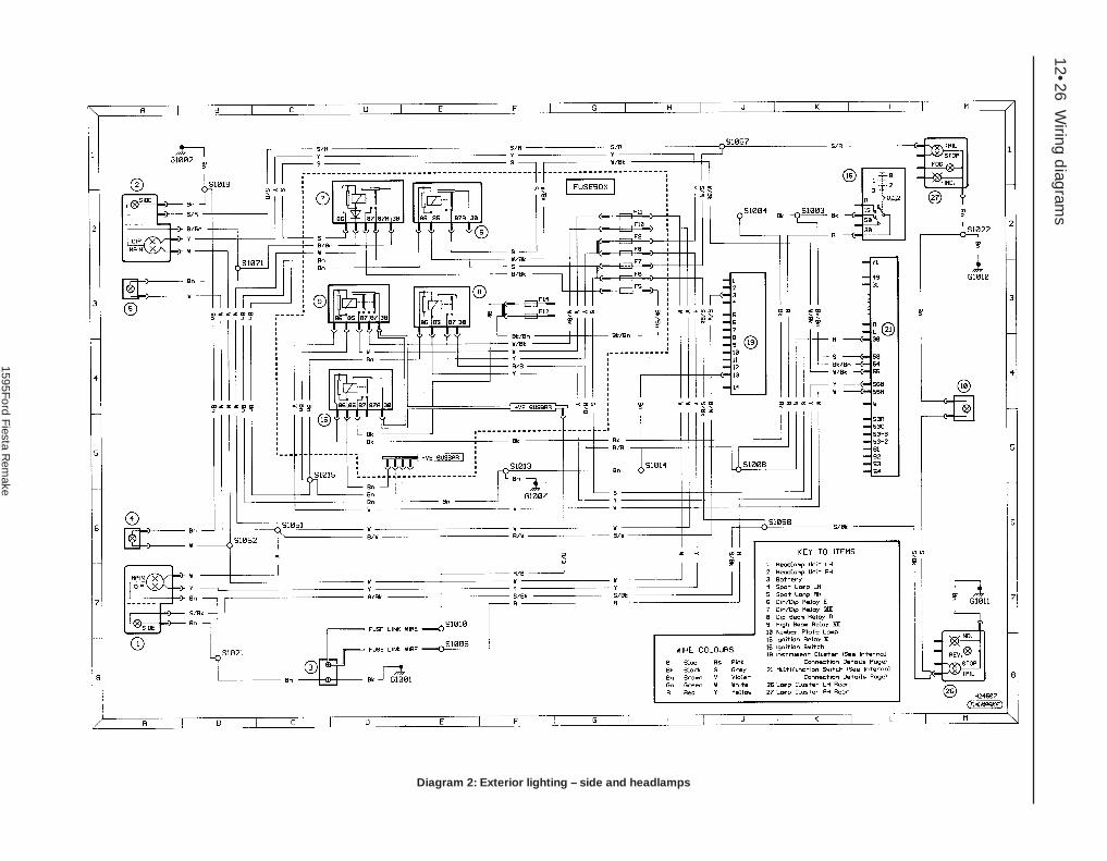
12•26W
iring diagram
s
Diagram 2: Exterior lighting – side and headlamps
1595Ford Fiesta R
emake

Wiring d
iagrams 12•27Diagram 2a: Exterior lighting – stop, reversing, fog and direction indicator lamps
12
1595Ford Fiesta R
emake

12•28W
iring diagram
s
Diagram 2b: Interior lighting, lights-on warning buzzer, clock and cigar lighter
1595Ford Fiesta R
emake

Wiring d
iagrams 12•29Diagram 3: Ancillary circuits – horn (except XR2i/RS models), heater blower and heated front /rear screens
12
1595Ford Fiesta R
emake

12•30W
iring diagram
s
Diagram 3a: Ancillary circuits – horn (R2i and RS models) and wash/wipe
1595Ford Fiesta R
emake

Wiring d
iagrams 12•31Diagram 3b: Ancillary circuits – central locking, electric windows and tailgate release (up to 1992)
12
1595Ford Fiesta R
emake

12•32W
iring diagram
s
Diagram 3c: Ancillary circuits – central locking, electric windows and tailgate release (1992-on)
1595Ford Fiesta R
emake

Wiring d
iagrams 12•33Diagram 4: In-car entertainment
12
1595Ford Fiesta R
emake

1595 Ford Fiesta Remake
REF
Dimensions and weightsNote: All figures are approximate, and may vary according to model. Refer to manufacturer’s data for exact figures.
DimensionsOverall length:
3/5 door hatchback models . . . . . . . . . . . . . . . . . . . . . . . . . . . . . . . . 3743 mmXR2i, RS Turbo and RS 1800 models . . . . . . . . . . . . . . . . . . . . . . . . . 3801 mmCourier models . . . . . . . . . . . . . . . . . . . . . . . . . . . . . . . . . . . . . . . . . . 4052 mm
Width (excluding mirrors): 3/5 door hatchback models . . . . . . . . . . . . . . . . . . . . . . . . . . . . . . . . 1606 mmXR2i, RS Turbo and RS 1800 models . . . . . . . . . . . . . . . . . . . . . . . . . 1630 mmCourier models . . . . . . . . . . . . . . . . . . . . . . . . . . . . . . . . . . . . . . . . . . 1650 mm
Overall height: 3/5 door hatchback models . . . . . . . . . . . . . . . . . . . . . . . . . . . . . . . . 1376 mmXR2i, RS Turbo and RS 1800 models . . . . . . . . . . . . . . . . . . . . . . . . . 1365 mmCourier models . . . . . . . . . . . . . . . . . . . . . . . . . . . . . . . . . . . . . . . . . . 1812 mm
Wheelbase:Courier models . . . . . . . . . . . . . . . . . . . . . . . . . . . . . . . . . . . . . . . . . . 2700 mmAll other models . . . . . . . . . . . . . . . . . . . . . . . . . . . . . . . . . . . . . . . . . 2446 mm
Front track: 3/5 door hatchback models . . . . . . . . . . . . . . . . . . . . . . . . . . . . . . . . 1392 mmXR2i, RS Turbo and RS 1800 models . . . . . . . . . . . . . . . . . . . . . . . . . 1406 mmCourier models . . . . . . . . . . . . . . . . . . . . . . . . . . . . . . . . . . . . . . . . . . 1392 mm
Rear track: 3/5 door hatchback models . . . . . . . . . . . . . . . . . . . . . . . . . . . . . . . . 1384 mmXR2i, RS Turbo and RS 1800 models . . . . . . . . . . . . . . . . . . . . . . . . . 1376 mmCourier models . . . . . . . . . . . . . . . . . . . . . . . . . . . . . . . . . . . . . . . . . . 1395 mm
Dimensions and weights . . . . . . . . . . . . . . . .REF•1Vehicle identification . . . . . . . . . . . . . . . . . . .REF•3General repair procedures . . . . . . . . . . . . . .REF•4Jacking and vehicle support . . . . . . . . . . . . .REF•5Buying spare parts . . . . . . . . . . . . . . . . . . . .REF•5Radio/cassette unit anti-theft system . . . . .REF•5
Conversion factors . . . . . . . . . . . . . . . . . . . .REF•6Tools and working facilities . . . . . . . . . . . . . .REF•7MOT test checks . . . . . . . . . . . . . . . . . . . . .REF•10Fault finding . . . . . . . . . . . . . . . . . . . . . . . .REF•14Glossary of technical terms . . . . . . . . . . . .REF•22Index . . . . . . . . . . . . . . . . . . . . . . . . . . . . . .REF•27
Reference REF•1

1595 Ford Fiesta Remake
REF•2 Conversion factorsWeightsKerb weight*:
3-door hatchback:1.0 litre models . . . . . . . . . . . . . . . . . . . . . . . . . . . . . . . . . . . . . . . . 770 to 780 kg1.1 litre models . . . . . . . . . . . . . . . . . . . . . . . . . . . . . . . . . . . . . . . . 785 to 850 kg1.3 litre models . . . . . . . . . . . . . . . . . . . . . . . . . . . . . . . . . . . . . . . . 825 to 870 kg1.4 litre models . . . . . . . . . . . . . . . . . . . . . . . . . . . . . . . . . . . . . . . . 920 to 940 kg1.6 litre models . . . . . . . . . . . . . . . . . . . . . . . . . . . . . . . . . . . . . . . . 990 to 1010 kgXR2i (1.6 litre) models . . . . . . . . . . . . . . . . . . . . . . . . . . . . . . . . . . . 890 to 910 kgXR2i (1.8 litre) models . . . . . . . . . . . . . . . . . . . . . . . . . . . . . . . . . . . 955 to 974 kgRS Turbo models . . . . . . . . . . . . . . . . . . . . . . . . . . . . . . . . . . . . . . 910 to 930 kgRS 1800 models . . . . . . . . . . . . . . . . . . . . . . . . . . . . . . . . . . . . . . . 954 to 965 kg
5-door hatchback:1.0 litre models . . . . . . . . . . . . . . . . . . . . . . . . . . . . . . . . . . . . . . . . 795 to 810 kg 1.1 litre models . . . . . . . . . . . . . . . . . . . . . . . . . . . . . . . . . . . . . . . . 810 to 845 kg1.3 litre models . . . . . . . . . . . . . . . . . . . . . . . . . . . . . . . . . . . . . . . . 845 to 870 kg1.4 litre models . . . . . . . . . . . . . . . . . . . . . . . . . . . . . . . . . . . . . . . . 840 to 870 kg1.6 litre models . . . . . . . . . . . . . . . . . . . . . . . . . . . . . . . . . . . . . . . . 980 to 1029 kg
Vans:1.0 litre models . . . . . . . . . . . . . . . . . . . . . . . . . . . . . . . . . . . . . . . . 775 kg1.1 litre models . . . . . . . . . . . . . . . . . . . . . . . . . . . . . . . . . . . . . . . . 775 to 790 kg1.3 litre models . . . . . . . . . . . . . . . . . . . . . . . . . . . . . . . . . . . . . . . . 795 kgCourier models . . . . . . . . . . . . . . . . . . . . . . . . . . . . . . . . . . . . . . . . 920 kg
Payload:1.0 litre Van models . . . . . . . . . . . . . . . . . . . . . . . . . . . . . . . . . . . . 310 to 335 kg1.1 litre Van models . . . . . . . . . . . . . . . . . . . . . . . . . . . . . . . . . . . . 310 to 335 kg1.3 litre Van models . . . . . . . . . . . . . . . . . . . . . . . . . . . . . . . . . . . . 330 kgCourier models . . . . . . . . . . . . . . . . . . . . . . . . . . . . . . . . . . . . . . . . 515 to 525 kg
Maximum roof rack load . . . . . . . . . . . . . . . . . . . . . . . . . . . . . . . . . . . 75 kgMaximum towing weight . . . . . . . . . . . . . . . . . . . . . . . . . . . . . . . . . . . Refer to your Ford dealer for weights and legal requirements
concerning anticipated gradients and altitudes.*Exact kerb weight varies depending on model - refer to VIN plate for details

1595 Ford Fiesta Remake
Modifications are a continuing andunpublicised process in vehicle manufacture,quite apart from major model changes. Spareparts manuals and lists are compiled upon anumerical basis, the individual vehicle identi-fication numbers being essential to correctidentification of the component concerned.
When ordering spare parts, always give asmuch information as possible. Quote the
vehicle model, year of manufacture, body andengine numbers as appropriate.
The vehicle identification plate is located onthe top of the front crossmember in theengine compartment (see illustration). Inaddition to many other details, it carries theVehicle Identification Number (VIN), maximumvehicle weight information, and codes forinterior trim and body colours.
The Vehicle Identification Number (VIN) isgiven on the vehicle identification plate (seeillustration). It is also located in a recess inthe floor to the right-hand side of the driver’sseat, access being gained after lifting theaperture cover. On later models, the numberis also stamped on a metal tag fixed to theleft-hand side of the facia, which can be readthrough the windscreen.
The body number and paint code numbersare located on the vehicle identification plate.
The engine number location is dependenton the engine type. On the HCS engines, it isstamped on the front left-hand side of thecylinder block towards the transmission(facing the radiator) (see illustration). On theCVH and PTE engines, the location of theengine number is dependent on theequipment fitted, but is on the exhaust side ofthe engine, facing either towards the timingbelt end or the transmission end (seeillustration). On the Zetec engines, thenumber can be found on the forward-facingside of the cylinder block, level with the startermotor, or on the cylinder head just above thethermostat housing (see illustration).
Buying spare parts REF•3
REF
Vehicle identification
Vehicle identification plate
HCS engine identification numberslocation
A Engine code (side or upper face)B Serial number
CVH and PTE engine identification numberlocation is on (A) the right-hand side or (B)the left-hand side, according to model and
equipment
Zetec engine identification number onforward-facing side of cylinder block levelwith the starter motor (A), or on cylinderhead just above thermostat housing (B)

1595 Ford Fiesta Remake
REF•4 General repair proceduresWhenever servicing, repair or overhaul work
is carried out on the car or its components,observe the following procedures andinstructions. This will assist in carrying out theoperation efficiently and to a professionalstandard of workmanship.
Joint mating faces and gasketsWhen separating components at their
mating faces, never insert screwdrivers orsimilar implements into the joint between thefaces in order to prise them apart. This cancause severe damage which results in oilleaks, coolant leaks, etc upon reassembly.Separation is usually achieved by tappingalong the joint with a soft-faced hammer inorder to break the seal. However, note thatthis method may not be suitable wheredowels are used for component location.
Where a gasket is used between the matingfaces of two components, a new one must befitted on reassembly; fit it dry unless otherwisestated in the repair procedure. Make sure thatthe mating faces are clean and dry, with alltraces of old gasket removed. When cleaning ajoint face, use a tool which is unlikely to scoreor damage the face, and remove any burrs ornicks with an oilstone or fine file.
Make sure that tapped holes are cleanedwith a pipe cleaner, and keep them free ofjointing compound, if this is being used,unless specifically instructed otherwise.
Ensure that all orifices, channels or pipesare clear, and blow through them, preferablyusing compressed air.
Oil sealsOil seals can be removed by levering them
out with a wide flat-bladed screwdriver orsimilar implement. Alternatively, a number ofself-tapping screws may be screwed into theseal, and these used as a purchase for pliers orsome similar device in order to pull the seal free.
Whenever an oil seal is removed from itsworking location, either individually or as partof an assembly, it should be renewed.
The very fine sealing lip of the seal is easilydamaged, and will not seal if the surface itcontacts is not completely clean and free fromscratches, nicks or grooves. If the originalsealing surface of the component cannot berestored, and the manufacturer has not madeprovision for slight relocation of the sealrelative to the sealing surface, the componentshould be renewed.
Protect the lips of the seal from any surfacewhich may damage them in the course offitting. Use tape or a conical sleeve wherepossible. Lubricate the seal lips with oil beforefitting and, on dual-lipped seals, fill the spacebetween the lips with grease.
Unless otherwise stated, oil seals must befitted with their sealing lips toward thelubricant to be sealed.
Use a tubular drift or block of wood of theappropriate size to install the seal and, if theseal housing is shouldered, drive the sealdown to the shoulder. If the seal housing is
unshouldered, the seal should be fitted withits face flush with the housing top face (unlessotherwise instructed).
Screw threads and fasteningsSeized nuts, bolts and screws are quite a
common occurrence where corrosion has setin, and the use of penetrating oil or releasingfluid will often overcome this problem if theoffending item is soaked for a while beforeattempting to release it. The use of an impactdriver may also provide a means of releasingsuch stubborn fastening devices, when usedin conjunction with the appropriatescrewdriver bit or socket. If none of thesemethods works, it may be necessary to resortto the careful application of heat, or the use ofa hacksaw or nut splitter device.
Studs are usually removed by locking twonuts together on the threaded part, and thenusing a spanner on the lower nut to unscrewthe stud. Studs or bolts which have broken offbelow the surface of the component in whichthey are mounted can sometimes be removedusing a stud extractor. Always ensure that ablind tapped hole is completely free from oil,grease, water or other fluid before installingthe bolt or stud. Failure to do this could causethe housing to crack due to the hydraulicaction of the bolt or stud as it is screwed in.
When tightening a castellated nut to accepta split pin, tighten the nut to the specifiedtorque, where applicable, and then tightenfurther to the next split pin hole. Never slackenthe nut to align the split pin hole, unless statedin the repair procedure.
When checking or retightening a nut or boltto a specified torque setting, slacken the nutor bolt by a quarter of a turn, and thenretighten to the specified setting. However,this should not be attempted where angulartightening has been used.
For some screw fastenings, notablycylinder head bolts or nuts, torque wrenchsettings are no longer specified for the latterstages of tightening, “angle-tightening” beingcalled up instead. Typically, a fairly low torquewrench setting will be applied to thebolts/nuts in the correct sequence, followedby one or more stages of tightening throughspecified angles.
Locknuts, locktabs and washersAny fastening which will rotate against a
component or housing during tighteningshould always have a washer between it andthe relevant component or housing.
Spring or split washers should always berenewed when they are used to lock a criticalcomponent such as a big-end bearingretaining bolt or nut. Locktabs which arefolded over to retain a nut or bolt shouldalways be renewed.
Self-locking nuts can be re-used in non-critical areas, providing resistance can be feltwhen the locking portion passes over the boltor stud thread. However, it should be notedthat self-locking stiffnuts tend to lose their
effectiveness after long periods of use, andshould then be renewed as a matter of course.
Split pins must always be replaced withnew ones of the correct size for the hole.
When thread-locking compound is foundon the threads of a fastener which is to be re-used, it should be cleaned off with a wirebrush and solvent, and fresh compoundapplied on reassembly.
Special toolsSome repair procedures in this manual
entail the use of special tools such as a press,two or three-legged pullers, spring com-pressors, etc. Wherever possible, suitablereadily-available alternatives to the manu-facturer’s special tools are described, and areshown in use. In some instances, where noalternative is possible, it has been necessaryto resort to the use of a manufacturer’s tool,and this has been done for reasons of safetyas well as the efficient completion of the repairoperation. Unless you are highly-skilled andhave a thorough understanding of theprocedures described, never attempt tobypass the use of any special tool when theprocedure described specifies its use. Notonly is there a very great risk of personalinjury, but expensive damage could becaused to the components involved.
Environmental considerationsWhen disposing of used engine oil, brake
fluid, antifreeze, etc, give due consideration toany detrimental environmental effects. Do not,for instance, pour any of the above liquidsdown drains into the general sewage system,or onto the ground to soak away. Many localcouncil refuse tips provide a facility for wasteoil disposal, as do some garages. If none ofthese facilities are available, consult your localEnvironmental Health Department, or theNational Rivers Authority, for further advice.
With the universal tightening-up of legis-lation regarding the emission of environmen-tally-harmful substances from motor vehicles,most vehicles have tamperproof devices fittedto the main adjustment points of the fuelsystem. These devices are primarily designedto prevent unqualified persons from adjustingthe fuel/air mixture, with the chance of aconsequent increase in toxic emissions. Ifsuch devices are found during servicing oroverhaul, they should, wherever possible, berenewed or refitted in accordance with themanufacturer’s requirements or currentlegislation.
Note: It isantisocial andillegal to dumpoil down thedrain. To findthe location ofyour local oilrecyclingbank, call thisnumber free.

1595 Ford Fiesta Remake
The jack supplied with the vehicle tool kitshould only be used for changing theroadwheels - see “Wheel changing” at thefront of this manual. When jacking up thevehicle to carry out repair or maintenancetasks, a pillar or trolley type jack of suitablelifting capacity must be used, supplementedwith axle stands positioned only beneath theappropriate points under the vehicle (seeillustration). Note that the vehicle must neverbe jacked up at the rear under the axle beam.
The maximum kerb weight of the vehicle mustnot be exceeded when jacking and supportingthe vehicle. Do not under any circumstancesjack up the rear of the vehicle under the rear axle.Never work under, around or near a raisedvehicle unless it is adequately supported in atleast two places with axle stands.
The radio/cassette unit fitted as standard oroptional equipment may be equipped with abuilt-in security code, to deter thieves. If thepower source to the unit is cut, the anti-theftsystem will activate. Even if the power sourceis immediately reconnected, the radio/cassette unit will not function until the correct
security code has been entered. Therefore,if you do not know the correct security
code for the radio/cassette unit do notdisconnect either of the battery terminals, orremove the radio/cassette unit from thevehicle.
To enter the correct security code, follow
the instructions provided with theradio/cassette player or vehicle handbook.
If an incorrect code is entered, the unit willbecome locked, and cannot be operated.
If this happens, or if the security code is lostor forgotten, seek the advice of your Forddealer.
Jacking and vehicle support REF•5
REF
Radio/cassette unit anti-theft system - precaution
Underside view of the vehicle showing the jacking point locations
A Jacking points for trolley jack(always use a suitable blockof wood to protect thevehicle body)
B Axle stand positionsC Jacking points for owner jack
and wheel-free hoist
Buying spare partsSpare parts are available from many
sources, including maker’s appointedgarages, accessory shops, and motor factors.To be sure of obtaining the correct parts, itwill sometimes be necessary to quote thevehicle identification number. If possible, itcan also be useful to take the old parts alongfor positive identification. Items such asstarter motors and alternators may beavailable under a service exchange scheme -any parts returned should always be clean.
Our advice regarding spare part sources isas follows.
Officially-appointed garagesThis is the best source of parts which are
peculiar to your car, and which are nototherwise generally available (eg badges,interior trim, certain body panels, etc). It isalso the only place at which you should buyparts if the vehicle is still under warranty.
Accessory shopsThese are very good places to buy
materials and components needed for themaintenance of your car (oil, air and fuelfilters, spark plugs, light bulbs, drivebelts, oilsand greases, brake pads, touch-up paint, etc).Components of this nature sold by areputable shop are of the same standard asthose used by the car manufacturer.
Besides components, these shops also selltools and general accessories, usually haveconvenient opening hours, charge lowerprices, and can often be found not far fromhome. Some accessory shops have partscounters where the components needed foralmost any repair job can be purchased orordered.
Motor factorsGood factors will stock all the more
important components which wear outcomparatively quickly, and can sometimessupply individual components needed for theoverhaul of a larger assembly (eg brake sealsand hydraulic parts, bearing shells, pistons,valves, alternator brushes). They may alsohandle work such as cylinder block reboring,crankshaft regrinding and balancing, etc.
Tyre and exhaust specialistsThese outlets may be independent, or
members of a local or national chain. Theyfrequently offer competitive prices whencompared with a main dealer or local garage,but it will pay to obtain several quotes beforemaking a decision. When researching prices,also ask what “extras” may be added - forinstance, fitting a new valve and balancing thewheel are both commonly charged on top ofthe price of a new tyre.
Other sourcesBeware of parts or materials obtained from
market stalls, car boot sales or similar outlets.Such items are not invariably sub-standard,but there is little chance of compensation ifthey do prove unsatisfactory. In the case ofsafety-critical components such as brakepads, there is the risk not only of financial lossbut also of an accident causing injury ordeath.
Second-hand components or assembliesobtained from a car breaker can be a goodbuy in some circumstances, but this sort ofpurchase is best made by the experiencedDIY mechanic.
Buying spare parts

REF•6 Conversion Factors
1595 Ford Fiesta Remake
Length (distance)Inches (in) x 25.4 = Millimetres (mm) x 0.0394 = Inches (in)Feet (ft) x 0.305 = Metres (m) x 3.281 = Feet (ft)Miles x 1.609 = Kilometres (km) x 0.621 = Miles
Volume (capacity)Cubic inches (cu in; in3) x 16.387 = Cubic centimetres (cc; cm3) x 0.061 = Cubic inches (cu in; in3)Imperial pints (Imp pt) x 0.568 = Litres (l) x 1.76 = Imperial pints (Imp pt)Imperial quarts (Imp qt) x 1.137 = Litres (l) x 0.88 = Imperial quarts (Imp qt)Imperial quarts (Imp qt) x 1.201 = US quarts (US qt) x 0.833 = Imperial quarts (Imp qt)US quarts (US qt) x 0.946 = Litres (l) x 1.057 = US quarts (US qt)Imperial gallons (Imp gal) x 4.546 = Litres (l) x 0.22 = Imperial gallons (Imp gal)Imperial gallons (Imp gal) x 1.201 = US gallons (US gal) x 0.833 = Imperial gallons (Imp gal)US gallons (US gal) x 3.785 = Litres (l) x 0.264 = US gallons (US gal)
Mass (weight)Ounces (oz) x 28.35 = Grams (g) x 0.035 = Ounces (oz)Pounds (lb) x 0.454 = Kilograms (kg) x 2.205 = Pounds (lb)
ForceOunces-force (ozf; oz) x 0.278 = Newtons (N) x 3.6 = Ounces-force (ozf; oz)Pounds-force (lbf; lb) x 4.448 = Newtons (N) x 0.225 = Pounds-force (lbf; lb)Newtons (N) x 0.1 = Kilograms-force (kgf; kg) x 9.81 = Newtons (N)
PressurePounds-force per square inch x 0.070 = Kilograms-force per square x 14.223 = Pounds-force per square inch(psi; lbf/in2; lb/in2) centimetre (kgf/cm2; kg/cm2) (psi; lbf/in2; lb/in2)Pounds-force per square inch x 0.068 = Atmospheres (atm) x 14.696 = Pounds-force per square inch(psi; lbf/in2; lb/in2) (psi; lbf/in2; lb/in2)Pounds-force per square inch x 0.069 = Bars x 14.5 = Pounds-force per square inch(psi; lbf/in2; lb/in2) (psi; lbf/in2; lb/in2)Pounds-force per square inch x 6.895 = Kilopascals (kPa) x 0.145 = Pounds-force per square inch(psi; lbf/in2; lb/in2) (psi; lbf/in2; lb/in2)Kilopascals (kPa) x 0.01 = Kilograms-force per square x 98.1 = Kilopascals (kPa)
centimetre (kgf/cm2; kg/cm2)Millibar (mbar) x 100 = Pascals (Pa) x 0.01 = Millibar (mbar)Millibar (mbar) x 0.0145 = Pounds-force per square inch x 68.947 = Millibar (mbar)
(psi; lbf/in2; lb/in2)Millibar (mbar) x 0.75 = Millimetres of mercury (mmHg) x 1.333 = Millibar (mbar)Millibar (mbar) x 0.401 = Inches of water (inH2O) x 2.491 = Millibar (mbar)Millimetres of mercury (mmHg) x 0.535 = Inches of water (inH2O) x 1.868 = Millimetres of mercury (mmHg)Inches of water (inH2O) x 0.036 = Pounds-force per square inch x 27.68 = Inches of water (inH2O)
(psi; lbf/in2; lb/in2)
Torque (moment of force)Pounds-force inches x 1.152 = Kilograms-force centimetre x 0.868 = Pounds-force inches(lbf in; lb in) (kgf cm; kg cm) (lbf in; lb in)Pounds-force inches x 0.113 = Newton metres (Nm) x 8.85 = Pounds-force inches(lbf in; lb in) (lbf in; lb in)Pounds-force inches x 0.083 = Pounds-force feet (lbf ft; lb ft) x 12 = Pounds-force inches(lbf in; lb in) (lbf in; lb in)Pounds-force feet (lbf ft; lb ft) x 0.138 = Kilograms-force metres x 7.233 = Pounds-force feet (lbf ft; lb ft)
(kgf m; kg m)Pounds-force feet (lbf ft; lb ft) x 1.356 = Newton metres (Nm) x 0.738 = Pounds-force feet (lbf ft; lb ft)Newton metres (Nm) x 0.102 = Kilograms-force metres x 9.804 = Newton metres (Nm)
(kgf m; kg m)
PowerHorsepower (hp) x 745.7 = Watts (W) x 0.0013 = Horsepower (hp)
Velocity (speed)Miles per hour (miles/hr; mph) x 1.609 = Kilometres per hour (km/hr; kph) x 0.621 = Miles per hour (miles/hr; mph)
Fuel consumption*Miles per gallon (mpg) x 0.354 = Kilometres per litre (km/l) x 2.825 = Miles per gallon (mpg)
TemperatureDegrees Fahrenheit = (°C x 1.8) + 32 Degrees Celsius (Degrees Centigrade; °C) = (°F - 32) x 0.56
* It is common practice to convert from miles per gallon (mpg) to litres/100 kilometres (l/100km), where mpg x l/100 km = 282

IntroductionA selection of good tools is a fundamental
requirement for anyone contemplating themaintenance and repair of a motor vehicle.For the owner who does not possess any,their purchase will prove a considerableexpense, offsetting some of the savings madeby doing-it-yourself. However, provided thatthe tools purchased meet the relevant nationalsafety standards and are of good quality, theywill last for many years and prove anextremely worthwhile investment.
To help the average owner to decide whichtools are needed to carry out the various tasksdetailed in this manual, we have compiledthree lists of tools under the followingheadings: Maintenance and minor repair,Repair and overhaul, and Special. Newcomersto practical mechanics should start off withthe Maintenance and minor repair tool kit, andconfine themselves to the simpler jobs aroundthe vehicle. Then, as confidence andexperience grow, more difficult tasks can beundertaken, with extra tools being purchasedas, and when, they are needed. In this way, aMaintenance and minor repair tool kit can bebuilt up into a Repair and overhaul tool kit overa considerable period of time, without anymajor cash outlays. The experienced do-it-yourselfer will have a tool kit good enough formost repair and overhaul procedures, and willadd tools from the Special category when it isfelt that the expense is justified by the amountof use to which these tools will be put.
Maintenance and minor repair tool kit
The tools given in this list should beconsidered as a minimum requirement ifroutine maintenance, servicing and minorrepair operations are to be undertaken. Werecommend the purchase of combinationspanners (ring one end, open-ended theother); although more expensive than open-ended ones, they do give the advantages ofboth types of spanner.M Combination spanners: 8, 9, 10, 11, 12, 13,
14, 15, 16, 17, 19, 21, 22, 24 & 26 mmM Adjustable spanner - 35 mm jaw (approx)M Engine sump/gearbox drain plug key
(where applicable)M Set of feeler gaugesM Spark plug spanner (with rubber insert)M Spark plug gap adjustment toolM Brake bleed nipple spannerM Screwdrivers: Flat blade and cross blade –
approx 100 mm long x 6 mm diaM Combination pliersM Hacksaw (junior)M Tyre pumpM Tyre pressure gaugeM Grease gunM Oil canM Oil filter removal toolM Fine emery clothM Wire brush (small)M Funnel (medium size)
Repair and overhaul tool kitThese tools are virtually essential for
anyone undertaking any major repairs to amotor vehicle, and are additional to thosegiven in the Maintenance and minor repair list.Included in this list is a comprehensive set ofsockets. Although these are expensive, theywill be found invaluable as they are soversatile - particularly if various drives areincluded in the set. We recommend the half-inch square-drive type, as this can be usedwith most proprietary torque wrenches. If youcannot afford a socket set, even boughtpiecemeal, then inexpensive tubular boxspanners are a useful alternative.
The tools in this list will occasionally needto be supplemented by tools from the Speciallist:M Sockets (or box spanners) to cover range in
previous list (including Torx sockets)M Reversible ratchet drive (for use with
sockets) (see illustration)M Extension piece, 250 mm (for use with
sockets)M Universal joint (for use with sockets)M Torque wrench (for use with sockets)M Self-locking gripsM Ball pein hammerM Soft-faced mallet (plastic/aluminium or
rubber)M Screwdrivers:
Flat blade - long & sturdy, short (chubby), and narrow (electrician’s) typesCross blade - Long & sturdy, and short(chubby) types
M Pliers:Long-nosedSide cutters (electrician’s)Circlip (internal and external)
M Cold chisel - 25 mmM ScriberM ScraperM Centre-punchM Pin punchM HacksawM Brake hose clampM Brake bleeding kitM Selection of twist drills
M Steel rule/straight-edgeM Allen keys (inc. splined/Torx type) (see
illustrations)M Selection of filesM Wire brushM Axle standsM Jack (strong trolley or hydraulic type)M Light with extension lead
Special toolsThe tools in this list are those which are not
used regularly, are expensive to buy, or whichneed to be used in accordance with theirmanufacturers’ instructions. Unless relativelydifficult mechanical jobs are undertakenfrequently, it will not be economic to buymany of these tools. Where this is the case,you could consider clubbing together withfriends (or joining a motorists’ club) to make ajoint purchase, or borrowing the tools againsta deposit from a local garage or tool hirespecialist. It is worth noting that many of thelarger DIY superstores now carry a largerange of special tools for hire at modest rates.
The following list contains only those toolsand instruments freely available to the public,and not those special tools produced by thevehicle manufacturer specifically for its dealernetwork. You will find occasional referencesto these manufacturers’ special tools in thetext of this manual. Generally, an alternativemethod of doing the job without the vehiclemanufacturers’ special tool is given. However,sometimes there is no alternative to usingthem. Where this is the case and the relevanttool cannot be bought or borrowed, you willhave to entrust the work to a franchisedgarage.M Valve spring compressor (see illustration)M Valve grinding toolM Piston ring compressor (see illustration)M Piston ring removal/installation tool (see
illustration)M Cylinder bore hone (see illustration)M Balljoint separatorM Coil spring compressors (where applicable)M Two/three-legged hub and bearing puller
(see illustration)
Sockets and reversible ratchet drive Spline bit set
Tools and working facilities REF•7
REF
1595 Ford Fiesta Remake

Spline key set Valve spring compressor Piston ring compressor
Compression testing gauge Clutch plate alignment set Brake shoe steady spring cup removal tool
Piston ring removal/installation tool Cylinder bore hone Three-legged hub and bearing puller
Micrometer set Vernier calipers Dial test indicator and magnetic stand
1595 Ford Fiesta Remake
REF•8 Tools and working facilities

M Impact screwdriverM Micrometer and/or vernier calipers (see
illustrations)M Dial gauge (see illustration)M Universal electrical multi-meterM Cylinder compression gauge
(see illustration)M Clutch plate alignment set (see
illustration)M Brake shoe steady spring cup removal tool
(see illustration)M Bush and bearing removal/installation set
(see illustration)M Stud extractors (see illustration)M Tap and die set (see illustration)M Lifting tackleM Trolley jack
Buying toolsFor practically all tools, a tool factor is the
best source, since he will have a verycomprehensive range compared with theaverage garage or accessory shop. Havingsaid that, accessory shops often offerexcellent quality tools at discount prices, so itpays to shop around.
Remember, you don’t have to buy the mostexpensive items on the shelf, but it is alwaysadvisable to steer clear of the very cheaptools. There are plenty of good tools around at
reasonable prices, but always aim topurchase items which meet the relevantnational safety standards. If in doubt, ask theproprietor or manager of the shop for advicebefore making a purchase.
Care and maintenance of toolsHaving purchased a reasonable tool kit, it is
necessary to keep the tools in a clean andserviceable condition. After use, always wipeoff any dirt, grease and metal particles using aclean, dry cloth, before putting the tools away.Never leave them lying around after they havebeen used. A simple tool rack on the garageor workshop wall for items such asscrewdrivers and pliers is a good idea. Storeall normal spanners and sockets in a metalbox. Any measuring instruments, gauges,meters, etc, must be carefully stored wherethey cannot be damaged or become rusty.
Take a little care when tools are used.Hammer heads inevitably become marked,and screwdrivers lose the keen edge on theirblades from time to time. A little timelyattention with emery cloth or a file will soonrestore items like this to a good serviceablefinish.
Working facilitiesNot to be forgotten when discussing tools
is the workshop itself. If anything more thanroutine maintenance is to be carried out,some form of suitable working area becomesessential.
It is appreciated that many an owner-mechanic is forced by circumstances toremove an engine or similar item without thebenefit of a garage or workshop. Having donethis, any repairs should always be done underthe cover of a roof.
Wherever possible, any dismantling shouldbe done on a clean, flat workbench or table ata suitable working height.
Any workbench needs a vice; one with ajaw opening of 100 mm is suitable for mostjobs. As mentioned previously, some cleandry storage space is also required for tools, aswell as for any lubricants, cleaning fluids,touch-up paints and so on, which becomenecessary.
Another item which may be required, andwhich has a much more general usage, is anelectric drill with a chuck capacity of at least 8mm. This, together with a good range of twistdrills, is virtually essential for fittingaccessories.
Last, but not least, always keep a supply ofold newspapers and clean, lint-free ragsavailable, and try to keep any working area asclean as possible.
Bush and bearing removal/installation set Stud extractor set Tap and die set
1595 Ford Fiesta Remake
Tools and working facilities REF•9
REF

1595 Ford Fiesta Remake
REF•10 MOT test checksThis is a guide to getting your vehicle through the MOT test.
Obviously it will not be possible to examine the vehicle to the samestandard as the professional MOT tester. However, working throughthe following checks will enable you to identify any problem areasbefore submitting the vehicle for the test.
Where a testable component is in borderline condition, the testerhas discretion in deciding whether to pass or fail it. The basis of suchdiscretion is whether the tester would be happy for a close relative orfriend to use the vehicle with the component in that condition. If thevehicle presented is clean and evidently well cared for, the tester maybe more inclined to pass a borderline component than if the vehicle isscruffy and apparently neglected.
It has only been possible to summarise the test requirements here,based on the regulations in force at the time of printing. Test standardsare becoming increasingly stringent, although there are someexemptions for older vehicles. For full details obtain a copy of the Haynespublication Pass the MOT! (available from stockists of Haynes manuals).
An assistant will be needed to help carry out some of these checks.
The checks have been sub-divided into four categories, as follows:
HandbrakeM Test the operation of the handbrake.Excessive travel (too many clicks) indicatesincorrect brake or cable adjustment.M Check that the handbrake cannot bereleased by tapping the lever sideways. Checkthe security of the lever mountings.
FootbrakeM Depress the brake pedal and check that itdoes not creep down to the floor, indicating amaster cylinder fault. Release the pedal, waita few seconds, then depress it again. If thepedal travels nearly to the floor before firmresistance is felt, brake adjustment or repair isnecessary. If the pedal feels spongy, there isair in the hydraulic system which must beremoved by bleeding.
M Check that the brake pedal is secure and ingood condition. Check also for signs of fluidleaks on the pedal, floor or carpets, whichwould indicate failed seals in the brake mastercylinder.M Check the servo unit (when applicable) byoperating the brake pedal several times, thenkeeping the pedal depressed and starting theengine. As the engine starts, the pedal willmove down slightly. If not, the vacuum hose orthe servo itself may be faulty.
Steering wheel and column M Examine the steering wheel for fractures orlooseness of the hub, spokes or rim. M Move the steering wheel from side to sideand then up and down. Check that the steering wheel is not loose on the column,indicating wear or a loose retaining nut.Continue moving the steering wheel as before,but also turn it slightly from left to right. M Check that the steering wheel is not looseon the column, and that there is no abnormal
movement of the steering wheel, indicatingwear in the column support bearings or couplings.
Windscreen and mirrors M The windscreen must be free of cracks orother significant damage within the driver’sfield of view. (Small stone chips areacceptable.) Rear view mirrors must besecure, intact, and capable of being adjusted.
1Checks carried outFROM THE DRIVER’S SEAT
1Checks carried outFROM THE DRIVER’SSEAT
2Checks carried outWITH THE VEHICLEON THE GROUND
3Checks carried outWITH THE VEHICLERAISED AND THEWHEELS FREE TOTURN
4Checks carried out onYOUR VEHICLE’SEXHAUST EMISSIONSYSTEM

1595 Ford Fiesta Remake
MOT test checks REF•11
REF
Seat belts and seats Note: The following checks are applicable toall seat belts, front and rear.
M Examine the webbing of all the belts(including rear belts if fitted) for cuts, seriousfraying or deterioration. Fasten and unfasteneach belt to check the buckles. If applicable,check the retracting mechanism. Check thesecurity of all seat belt mountings accessiblefrom inside the vehicle.M The front seats themselves must besecurely attached and the backrests mustlock in the upright position.
Doors M Both front doors must be able to be openedand closed from outside and inside, and mustlatch securely when closed.
Vehicle identificationM Number plates must be in good condition,secure and legible, with letters and numberscorrectly spaced – spacing at (A) should betwice that at (B).
M The VIN plate and/or homologation platemust be legible.
Electrical equipmentM Switch on the ignition and check the operation of the horn.M Check the windscreen washers and wipers,examining the wiper blades; renew damagedor perished blades. Also check the operationof the stop-lights.
M Check the operation of the sidelights andnumber plate lights. The lenses and reflectorsmust be secure, clean and undamaged. M Check the operation and alignment of theheadlights. The headlight reflectors must notbe tarnished and the lenses must beundamaged.M Switch on the ignition and check the operation of the direction indicators (includingthe instrument panel tell-tale) and the hazardwarning lights. Operation of the sidelights andstop-lights must not affect the indicators - if itdoes, the cause is usually a bad earth at therear light cluster.M Check the operation of the rear foglight(s),including the warning light on the instrumentpanel or in the switch.
FootbrakeM Examine the master cylinder, brake pipesand servo unit for leaks, loose mountings, corrosion or other damage.
M The fluid reservoir must be secure and thefluid level must be between the upper (A) andlower (B) markings.
M Inspect both front brake flexible hoses forcracks or deterioration of the rubber. Turn thesteering from lock to lock, and ensure that thehoses do not contact the wheel, tyre, or anypart of the steering or suspension mechanism.With the brake pedal firmly depressed, checkthe hoses for bulges or leaks under pressure.
Steering and suspensionM Have your assistant turn the steering wheelfrom side to side slightly, up to the point wherethe steering gear just begins to transmit thismovement to the roadwheels. Check forexcessive free play between the steeringwheel and the steering gear, indicating wear orinsecurity of the steering column joints, thecolumn-to-steering gear coupling, or thesteering gear itself.M Have your assistant turn the steering wheelmore vigorously in each direction, so that theroadwheels just begin to turn. As this is done,examine all the steering joints, linkages,fittings and attachments. Renew anycomponent that shows signs of wear or damage. On vehicles with power steering,check the security and condition of the steering pump, drivebelt and hoses.M Check that the vehicle is standing level,and at approximately the correct ride height.
Shock absorbersM Depress each corner of the vehicle in turn,then release it. The vehicle should rise andthen settle in its normal position. If the vehiclecontinues to rise and fall, the shock absorberis defective. A shock absorber which hasseized will also cause the vehicle to fail.
2Checks carried outWITH THE VEHICLE ON THEGROUND

1595 Ford Fiesta Remake
REF•12 MOT test checksExhaust systemM Start the engine. With your assistant holding a rag over the tailpipe, check theentire system for leaks. Repair or renewleaking sections.
Jack up the front and rear of the vehicle,and securely support it on axle stands.Position the stands clear of the suspensionassemblies. Ensure that the wheels areclear of the ground and that the steeringcan be turned from lock to lock.
Steering mechanism M Have your assistant turn the steering fromlock to lock. Check that the steering turnssmoothly, and that no part of the steeringmechanism, including a wheel or tyre, foulsany brake hose or pipe or any part of the bodystructure.M Examine the steering rack rubber gaitersfor damage or insecurity of the retaining clips.If power steering is fitted, check for signs ofdamage or leakage of the fluid hoses, pipes orconnections. Also check for excessivestiffness or binding of the steering, a missingsplit pin or locking device, or severe corrosionof the body structure within 30 cm of anysteering component attachment point.
Front and rear suspension andwheel bearings M Starting at the front right-hand side, graspthe roadwheel at the 3 o’clock and 9 o’clockpositions and shake it vigorously. Check forfree play or insecurity at the wheel bearings,suspension balljoints, or suspension mount-ings, pivots and attachments.M Now grasp the wheel at the 12 o’clock and6 o’clock positions and repeat the previousinspection. Spin the wheel, and check forroughness or tightness of the front wheelbearing.
M If excess free play is suspected at acomponent pivot point, this can be confirmedby using a large screwdriver or similar tool andlevering between the mounting and thecomponent attachment. This will confirmwhether the wear is in the pivot bush, itsretaining bolt, or in the mounting itself (the boltholes can often become elongated).
M Carry out all the above checks at the otherfront wheel, and then at both rear wheels.
Springs and shock absorbers M Examine the suspension struts (whenapplicable) for serious fluid leakage, corrosion,or damage to the casing. Also check thesecurity of the mounting points.M If coil springs are fitted, check that thespring ends locate in their seats, and that thespring is not corroded, cracked or broken.M If leaf springs are fitted, check that allleaves are intact, that the axle is securelyattached to each spring, and that there is nodeterioration of the spring eye mountings,bushes, and shackles.
M The same general checks apply to vehiclesfitted with other suspension types, such astorsion bars, hydraulic displacer units, etc.Ensure that all mountings and attachments aresecure, that there are no signs of excessivewear, corrosion or damage, and (on hydraulictypes) that there are no fluid leaks or damagedpipes.M Inspect the shock absorbers for signs ofserious fluid leakage. Check for wear of themounting bushes or attachments, or damageto the body of the unit.
Driveshafts(fwd vehicles only)M Rotate each front wheel in turn and inspectthe constant velocity joint gaiters for splits ordamage. Also check that each driveshaft isstraight and undamaged.
Braking system M If possible without dismantling, checkbrake pad wear and disc condition. Ensurethat the friction lining material has not wornexcessively, (A) and that the discs are notfractured, pitted, scored or badly worn (B).
M Examine all the rigid brake pipesunderneath the vehicle, and the flexiblehose(s) at the rear. Look for corrosion, chafingor insecurity of the pipes, and for signs ofbulging under pressure, chafing, splits ordeterioration of the flexible hoses.M Look for signs of fluid leaks at the brakecalipers or on the brake backplates. Repair orrenew leaking components.M Slowly spin each wheel, while yourassistant depresses and releases thefootbrake. Ensure that each brake is operatingand does not bind when the pedal is released.
3Checks carried outWITH THE VEHICLE RAISEDAND THE WHEELS FREE TOTURN

1595 Ford Fiesta Remake
MOT test checks REF•13
REF
M Examine the handbrake mechanism,checking for frayed or broken cables,excessive corrosion, or wear or insecurity ofthe linkage. Check that the mechanism workson each relevant wheel, and releases fully,without binding.M It is not possible to test brake efficiencywithout special equipment, but a road test canbe carried out later to check that the vehiclepulls up in a straight line.
Fuel and exhaust systemsM Inspect the fuel tank (including the fillercap), fuel pipes, hoses and unions. Allcomponents must be secure and free fromleaks.M Examine the exhaust system over its entirelength, checking for any damaged, broken ormissing mountings, security of the retainingclamps and rust or corrosion.
Wheels and tyres M Examine the sidewalls and tread area ofeach tyre in turn. Check for cuts, tears, lumps,bulges, separation of the tread, and exposureof the ply or cord due to wear or damage.Check that the tyre bead is correctly seatedon the wheel rim, that the valve is sound and
properly seated, and that the wheel is notdistorted or damaged. M Check that the tyres are of the correct sizefor the vehicle, that they are of the same sizeand type on each axle, and that the pressuresare correct.M Check the tyre tread depth. The legalminimum at the time of writing is 1.6 mm overat least three-quarters of the tread width.Abnormal tread wear may indicate incorrectfront wheel alignment.
Body corrosionM Check the condition of the entire vehiclestructure for signs of corrosion in load-bearingareas. (These include chassis box sections,side sills, cross-members, pillars, and allsuspension, steering, braking system andseat belt mountings and anchorages.) Anycorrosion which has seriously reduced thethickness of a load-bearing area is likely tocause the vehicle to fail. In this caseprofessional repairs are likely to be needed.M Damage or corrosion which causes sharpor otherwise dangerous edges to be exposedwill also cause the vehicle to fail.
Petrol modelsM Have the engine at normal operatingtemperature, and make sure that it is in goodtune (ignition system in good order, air filterelement clean, etc).M Before any measurements are carried out,raise the engine speed to around 2500 rpm,and hold it at this speed for 20 seconds. Allow
the engine speed to return to idle, and watchfor smoke emissions from the exhausttailpipe. If the idle speed is obviously muchtoo high, or if dense blue or clearly-visibleblack smoke comes from the tailpipe for morethan 5 seconds, the vehicle will fail. As a ruleof thumb, blue smoke signifies oil being burnt(engine wear) while black smoke signifiesunburnt fuel (dirty air cleaner element, or othercarburettor or fuel system fault).M An exhaust gas analyser capable ofmeasuring carbon monoxide (CO) andhydrocarbons (HC) is now needed. If such aninstrument cannot be hired or borrowed, alocal garage may agree to perform the checkfor a small fee.
CO emissions (mixture)M At the time of writing, the maximum COlevel at idle is 3.5% for vehicles first used afterAugust 1986 and 4.5% for older vehicles.From January 1996 a much tighter limit(around 0.5%) applies to catalyst-equippedvehicles first used from August 1992. If theCO level cannot be reduced far enough topass the test (and the fuel and ignitionsystems are otherwise in good condition) thenthe carburettor is badly worn, or there is someproblem in the fuel injection system orcatalytic converter (as applicable).
HC emissionsM With the CO emissions within limits, HCemissions must be no more than 1200 ppm(parts per million). If the vehicle fails this testat idle, it can be re-tested at around 2000 rpm;if the HC level is then 1200 ppm or less, thiscounts as a pass.M Excessive HC emissions can be caused byoil being burnt, but they are more likely to bedue to unburnt fuel.
Diesel modelsM The only emission test applicable to Dieselengines is the measuring of exhaust smokedensity. The test involves accelerating theengine several times to its maximumunloaded speed.
Note: It is of the utmost importance that theengine timing belt is in good condition beforethe test is carried out.
M Excessive smoke can be caused by a dirtyair cleaner element. Otherwise, professionaladvice may be needed to find the cause.
4Checks carried out onYOUR VEHICLE’S EXHAUSTEMISSION SYSTEM

The vehicle owner who does his or her ownmaintenance according to the recommendedservice schedules should not have to use thissection of the manual very often. Moderncomponent reliability is such that, providedthose items subject to wear or deteriorationare inspected or renewed at the specifiedintervals, sudden failure is comparatively rare.Faults do not usually just happen as a result ofsudden failure, but develop over a period oftime. Major mechanical failures in particular
are usually preceded by characteristicsymptoms over hundreds or even thousandsof miles. Those components which dooccasionally fail without warning are oftensmall and easily carried in the vehicle.
With any fault-finding, the first step is todecide where to begin investigations.Sometimes this is obvious, but on otheroccasions, a little detective work will benecessary. The owner who makes half adozen haphazard adjustments or
replacements may be successful in curing afault (or its symptoms), but will be none thewiser if the fault recurs, and ultimately mayhave spent more time and money than wasnecessary. A calm and logical approach willbe found to be more satisfactory in the longrun. Always take into account any warningsigns or abnormalities that may have beennoticed in the period preceding the fault -power loss, high or low gauge readings,unusual smells, etc - and remember that
Enginemm Engine backfiresmm Engine difficult to start when coldmm Engine difficult to start when hotmm Engine fails to rotate when attempting to startmm Engine hesitates on accelerationmm Engine idles erraticallymm Engine lacks powermm Engine misfires at idle speedmm Engine misfires throughout the driving speed rangemm Engine noisesmm Engine rotates, but will not startmm Engine runs-on after switching offmm Engine stallsmm Engine starts, but stops immediatelymm Oil pressure warning light illuminated with engine runningmm Starter motor noisy or excessively-rough in engagement
Cooling systemmm Corrosionmm External coolant leakagemm Internal coolant leakagemm Overcoolingmm Overheating
Fuel and exhaust systemsmm Excessive fuel consumptionmm Excessive noise or fumes from exhaust systemmm Fuel leakage and/or fuel odour
Clutchmm Clutch fails to disengage (unable to select gears)mm Clutch slips (engine speed increases, with no increase in vehicle
speed)mm Judder as clutch is engagedmm Noise when depressing or releasing clutch pedalmm Pedal travels to floor - no pressure or very little resistance
Manual transmissionmm Jumps out of gearmm Lubricant leaksmm Noisy in neutral with engine runningmm Noisy in one particular gearmm Vibration
Automatic transmissionmm Engine will not start in any gear, or starts in gears other than Park
or Neutralmm Fluid leakagemm General gear selection problemsmm Transmission fluid brown, or has burned smellmm Transmission slips, shifts roughly, is noisy, or has no drive in
forward or reverse gearsmm Transmission will not downshift (kickdown) with accelerator fully
depressed
Driveshaftsmm Clicking or knocking noise on turns (at slow speed on full-lock)mm Vibration when accelerating or decelerating
Braking systemmm Brake pedal feels spongy when depressedmm Brakes bindingmm Excessive brake pedal effort required to stop vehiclemm Excessive brake pedal travelmm Judder felt through brake pedal or steering wheel when brakingmm Noise (grinding or high-pitched squeal) when brakes appliedmm Rear wheels locking under normal brakingmm Vehicle pulls to one side under braking
Suspension and steering systemsmm Excessive pitching and/or rolling around corners, or during
brakingmm Excessive play in steeringmm Excessively-stiff steeringmm Lack of power assistancemm Tyre wear excessivemm Vehicle pulls to one sidemm Wandering or general instabilitymm Wheel wobble and vibration
Electrical systemmm Battery will not hold a charge for more than a few daysmm Electric windows inoperative, or unsatisfactory in operationmm Horn inoperative, or unsatisfactory in operationmm Ignition warning light fails to come onmm Ignition warning light remains illuminated with engine runningmm Instrument readings inaccurate or erraticmm Lights inoperativemm Windscreen/tailgate washers inoperative, or unsatisfactory in
operationmm Windscreen/tailgate wipers inoperative, or unsatisfactory in
operation
REF•14 Fault finding
1595 Ford Fiesta Remake
Introduction

1595 Ford Fiesta Remake
failure of components such as fuses or sparkplugs may only be pointers to someunderlying fault.
The pages which follow provide an easyreference guide to the more commonproblems which may occur during theoperation of the vehicle. These problems andtheir possible causes are grouped underheadings denoting various components orsystems, such as Engine, Cooling system,etc. The Chapter and/or Section which dealswith the problem is also shown in brackets.Whatever the fault, certain basic principlesapply. These are as follows:
Verify the fault. This is simply a matter ofbeing sure that you know what the symptoms
are before starting work. This is particularlyimportant if you are investigating a fault forsomeone else, who may not have described itvery accurately.
Don’t overlook the obvious. For example, ifthe vehicle won’t start, is there petrol in thetank? (Don’t take anyone else’s word on thisparticular point, and don’t trust the fuel gaugeeither!) If an electrical fault is indicated, lookfor loose or broken wires before digging outthe test gear.
Cure the disease, not the symptom.Substituting a flat battery with a fully-chargedone will get you off the hard shoulder, but ifthe underlying cause is not attended to, thenew battery will go the same way. Similarly,
changing oil-fouled spark plugs for a new setwill get you moving again, but remember thatthe reason for the fouling (if it wasn’t simply anincorrect grade of plug) will have to beestablished and corrected.
Don’t take anything for granted. Particularly,don’t forget that a “new” component mayitself be defective (especially if it’s beenrattling around in the boot for months), anddon’t leave components out of a faultdiagnosis sequence just because they arenew or recently fitted. When you do finallydiagnose a difficult fault, you’ll probablyrealise that all the evidence was there fromthe start.
Fault finding REF•15
REF
Engine
Engine fails to rotate when attempting to startmm Battery terminal connections loose or corroded (Chapter 5A).mm Battery discharged or faulty (Chapter 5A).mm Broken, loose or disconnected wiring in the starting circuit
(Chapter 5A).mm Defective starter solenoid or switch (Chapter 5A).mm Defective starter motor (Chapter 5A).mm Flywheel ring gear or starter pinion teeth loose or broken
(Chapters 2A, 2B, 2C or 5A).mm Engine earth strap broken or disconnected (Chapter 5A).mm Automatic transmission not in Park/Neutral position, or starter
inhibitor switch faulty (Chapter 7B).
Engine rotates, but will not startmm Fuel tank empty.mm Battery discharged (engine rotates slowly) (Chapter 5A).mm Battery terminal connections loose or corroded (Chapter 5A).mm Ignition components damp or damaged (Chapters 1 and 5B).mm Broken, loose or disconnected wiring in the ignition circuit
(Chapters 1 and 5B).mm Worn, faulty or incorrectly-gapped spark plugs (Chapter 1).mm Major mechanical failure (eg camshaft drive) (Chapters 2A, 2B
or 2C).
Engine difficult to start when coldmm Battery discharged (Chapter 5A).mm Battery terminal connections loose or corroded (Chapter 5A).mm Worn, faulty or incorrectly-gapped spark plugs (Chapter 1).mm Other ignition system fault (Chapters 1 and 5B).mm Engine management system fault (Chapters 1, 4A, 4B, 4C, 4D, 4E
or 5B).mm Low cylinder compressions (Chapters 2A, 2B or 2C).
Engine difficult to start when hotmm Air filter element dirty or clogged (Chapter 1).mm Engine management system fault (Chapters 1, 4A, 4B, 4C, 4D, 4E
or 5B).mm Low cylinder compressions (Chapters 2A, 2B or 2C).mm Faulty hydraulic tappet(s) (Chapters 2B or 2C).
Starter motor noisy or excessively-rough inengagementmm Flywheel ring gear or starter pinion teeth loose or broken
(Chapters 2A, 2B, 2C or 5A).mm Starter motor mounting bolts loose or missing (Chapter 5A).mm Starter motor internal components worn or damaged (Chapter 5A).
Engine starts but stops immediatelymm Loose or faulty electrical connections in the ignition circuit
(Chapters 1 and 5B).mm Engine management system fault (Chapters 1, 4A, 4B, 4C, 4D, 4E
or 5B).mm Vacuum leak at the inlet manifold (Chapters 1, 4A, 4B, 4C, 4D or 4E).
Engine idles erraticallymm Engine management system fault (Chapters 1, 4A, 4B, 4C, 4D, 4E
or 5B).mm Air filter element clogged (Chapter 1).mm Vacuum leak at the inlet manifold or associated hoses (Chap-
ters 1, 4A, 4B, 4C, 4D or 4E).mm Worn, faulty or incorrectly-gapped spark plugs (Chapter 1).mm Incorrect valve clearances (Chapter 2A).mm Faulty hydraulic tappet(s) (Chapters 2B or 2C).mm Uneven or low cylinder compressions (Chapters 2A, 2B or 2C).mm Camshaft lobes worn (Chapters 2A, 2B or 2C).mm Timing chain and sprockets worn (Chapter 2A).mm Timing belt incorrectly-tensioned (Chapters 2B or 2C).
Engine misfires at idle speedmm Worn, faulty or incorrectly-gapped spark plugs (Chapter 1).mm Faulty spark plug HT leads (Chapter 1).mm Engine management system fault (Chapters 1, 4A, 4B, 4C, 4D, 4E
or 5B).mm Vacuum leak at the inlet manifold or associated hoses (Chap-
ters 1, 4A, 4B, 4C, 4D or 4E).mm Incorrect valve clearances (Chapter 2A).mm Faulty hydraulic tappet(s) (Chapters 2B or 2C).mm Uneven or low cylinder compressions (Chapters 2A, 2B and 2C).mm Disconnected, leaking or perished crankcase ventilation hoses
(Chapters 1 and 4E).
Engine misfires throughout the driving speed rangemm Fuel filter choked (Chapter 1).mm Fuel pump faulty or delivery pressure low (Chapters 4A, 4B, 4C or 4D).mm Fuel tank vent blocked or fuel pipes restricted (Chapters 4A, 4B,
4C, 4D or 4E).mm Vacuum leak at the inlet manifold or associated hoses (Chap-
ters 1, 4A, 4B, 4C, 4D or 4E).mm Worn, faulty or incorrectly-gapped spark plugs (Chapter 1).mm Faulty spark plug HT leads (Chapter 1).mm Faulty ignition coil (Chapter 5B).mm Engine management system fault (Chapters 1, 4A, 4B, 4C, 4D, 4E
or 5B).mm Uneven or low cylinder compressions (Chapters 2A, 2B or 2C).

1595 Ford Fiesta Remake
REF•16 Fault finding
Cooling systemOverheatingmm Insufficient coolant in system (Chapter 1).mm Thermostat faulty (Chapter 3).mm Radiator core blocked or grille restricted (Chapter 3).mm Radiator electric cooling fan(s) or coolant temperature sensor
faulty Chapter 3).mm Engine management system fault (Chapters 1, 4A, 4B, 4C, 4D, 4E
or 5B).mm Pressure cap faulty (Chapter 3).mm Auxiliary drivebelt worn or slipping (Chapter 1).mm Inaccurate coolant temperature gauge sender (Chapter 3).mm Airlock in cooling system (Chapter 1).
Overcoolingmm Thermostat faulty (Chapter 3).mm Inaccurate coolant temperature gauge sender (Chapter 3).
External coolant leakagemm Deteriorated or damaged hoses or hose clips (Chapter 1).mm Radiator core or heater matrix leaking (Chapter 3).mm Pressure cap faulty (Chapter 3).mm Water pump seal leaking (Chapter 3).mm Boiling due to overheating (Chapter 3).mm Core plug leaking (Chapter 2D).
Internal coolant leakagemm Leaking cylinder head gasket (Chapters 2A, 2B or 2C).mm Cracked cylinder head or cylinder bore (Chapter 2D).
Corrosionmm Infrequent draining and flushing (Chapter 1).mm Incorrect antifreeze mixture, or inappropriate antifreeze type
(Chapters 1 and 3).
Engine (continued)Engine hesitates on accelerationmm Worn, faulty or incorrectly-gapped spark plugs (Chapter 1).mm Engine management system fault (Chapters 1, 4A, 4B, 4C, 4D, 4E
or 5B).mm Vacuum leak at the inlet manifold or associated hoses (Chap-
ters 1, 4A, 4B, 4C, 4D, 4E or 5B).
Engine stallsmm Engine management system fault (Chapters 1, 4A, 4B, 4C, 4D, 4E,
or 5B).mm Vacuum leak at the inlet manifold or associated hoses (Chap-
ters 1, 4A, 4B, 4C, 4D or 4E).mm Fuel filter choked (Chapter 1).mm Fuel pump faulty or delivery pressure low (Chapters 4A, 4B, 4C
or 4D).mm Fuel tank vent blocked or fuel pipes restricted (Chapters 4A, 4B,
4C. 4D or 4E).
Engine lacks powermm Engine management system fault (Chapters 1, 4A, 4B, 4C, 4D, 4E
or 5B).mm Timing chain or belt incorrectly fitted or incorrectly tensioned
(Chapters 2A, 2B or 2C).mm Fuel filter choked (Chapter 1).mm Fuel pump faulty or delivery pressure low (Chapters 4A, 4B, 4C
or 4D).mm Uneven or low cylinder compressions (Chapters 2A, 2B or 2C).mm Worn, faulty or incorrectly-gapped spark plugs (Chapter 1).mm Vacuum leak at the inlet manifold or associated hoses (Chap-
ters 1, 4A, 4B, 4C, 4D or 4E).mm Brakes binding (Chapters 1 and 9).mm Clutch slipping (Chapter 6).mm Automatic transmission fluid level incorrect (Chapter 1).
Oil pressure warning light illuminated with enginerunningmm Low oil level or incorrect oil grade (Chapter 1).mm Faulty oil pressure warning light switch (Chapters 2A, 2B or 2C).mm Worn engine bearings and/or oil pump (Chapters 2A, 2B, 2C
or 2D).mm High engine operating temperature (Chapter 3).mm Oil pressure relief valve defective (Chapters 2A, 2B or 2C).mm Oil pick-up strainer clogged (Chapters 2A, 2B or 2C).
Engine backfiresmm Engine management system fault (Chapters 1, 4A, 4B, 4C, 4D, 4E
or 5B).mm Timing chain or belt incorrectly fitted or incorrectly tensioned
(Chapters 2A, 2B or 2C).mm Vacuum leak at the inlet manifold or associated hoses (Chap-
ters 1, 4A, 4B, 4C, 4D or 4E).
Engine runs-on after switching offmm Idle speed excessively high (Chapters 4A, 4B, 4C or 4D).mm Engine management system fault (Chapters 1, 4A, 4B, 4C, 4D, 4E
or 5B).mm Excessive carbon build-up in engine (Chapters 2A, 2B or 2C).mm High engine operating temperature (Chapter 3).
Engine noisesPre-ignition (pinking) or knocking during acceleration orunder loadmm Incorrect grade of fuel (Chapters 4A, 4B, 4C or 4D).mm Vacuum leak at the inlet manifold or associated hoses (Chap-
ters 1, 4A, 4B, 4C, 4D or 4E).mm Excessive carbon build-up in engine (Chapters 2A, 2B or 2C).
Whistling or wheezing noisesmm Leaking inlet manifold gasket (Chapters 4A, 4B, 4C, 4D).mm Leaking exhaust manifold gasket or downpipe-to-manifold joint
(Chapter 4E).mm Leaking vacuum hose (Chapters 1, 4A, 4B, 4C, 4D, 4E or 9).mm Blowing cylinder head gasket (Chapters 2A, 2B or 2C).
Tapping or rattling noisesmm Incorrect valve clearance adjustment (Chapter 2A).mm Faulty hydraulic tappet(s) (Chapters 2B or 2C).mm Worn valve gear or camshaft (Chapters 2A, 2B, 2C or 2D).mm Worn timing chain, belt or tensioner (Chapters 2A, 2B or 2C).mm Ancillary component fault (water pump, alternator, etc) (Chapters 3
and 5A).
Knocking or thumping noisesmm Worn big-end bearings (regular heavy knocking, perhaps less
under load) Chapter 2D).mm Worn main bearings (rumbling and knocking, perhaps worsening
under load) Chapter 2D).mm Piston slap (most noticeable when cold) (Chapter 2D).mm Ancillary component fault (water pump, alternator, etc) (Chapters 3
and 5A).

1595 Ford Fiesta Remake
Fault finding REF•17
REF
Fuel and exhaust systemsExcessive fuel consumptionmm Unsympathetic driving style, or adverse conditions.mm Air filter element dirty or clogged (Chapter 1).mm Engine management system fault (Chapters 1, 4A, 4B, 4C, 4D, 4E
or 5B).mm Tyres under-inflated (“Weekly Checks”).
Fuel leakage and/or fuel odourmm Damaged or corroded fuel tank, pipes or connections (Chapter 1).mm Charcoal canister and/or connecting pipes leaking (Chapters 1
and 4E).
Excessive noise or fumes from exhaust systemmm Leaking exhaust system or manifold joints (Chapters 1 or 4E).mm Leaking, corroded or damaged silencers or pipe (Chapters 1 or 4E).mm Broken mountings, causing body or suspension contact (Chap-
ters 1 or 4E).
ClutchPedal travels to floor - no pressure or very littleresistancemm Broken clutch cable (Chapter 6).mm Faulty clutch automatic adjuster (Chapter 6).mm Broken clutch release bearing or fork (Chapter 6).mm Broken diaphragm spring in clutch pressure plate (Chapter 6).
Clutch fails to disengage (unable to select gears)mm Faulty clutch automatic adjuster (Chapter 6).mm Clutch disc sticking on transmission input shaft splines (Chapter 6).mm Clutch disc sticking to flywheel or pressure plate (Chapter 6).mm Faulty pressure plate assembly (Chapter 6).mm Clutch release mechanism worn or incorrectly assembled (Chapter 6).
Clutch slips (engine speed increases, with noincrease in vehicle speed)mm Faulty clutch automatic adjuster (Chapter 6).mm Clutch disc linings excessively worn (Chapter 6).mm Clutch disc linings contaminated with oil or grease (Chapter 6).mm Faulty pressure plate or weak diaphragm spring (Chapter 6).
Judder as clutch is engagedmm Clutch disc linings contaminated with oil or grease (Chapter 6).mm Clutch disc linings excessively worn (Chapter 6).mm Clutch cable sticking or frayed (Chapter 6).mm Faulty or distorted pressure plate or diaphragm spring (Chapter 6).mm Worn or loose engine/transmission mountings (Chapters 2A, 2B
or 2C).mm Clutch disc hub or transmission input shaft splines worn (Chap-
ter 6).
Noise when depressing or releasing clutch pedalmm Worn clutch release bearing (Chapter 6).mm Worn or dry clutch pedal bushes (Chapter 6).mm Faulty pressure plate assembly (Chapter 6).mm Pressure plate diaphragm spring broken (Chapter 6).mm Broken clutch disc cushioning springs (Chapter 6).
Manual transmissionNoisy in neutral with engine runningmm Input shaft bearings worn (noise apparent with clutch pedal
released, but not when depressed) (Chapter 7A).*mm Clutch release bearing worn (noise apparent with clutch pedal
depressed, possibly less when released) (Chapter 6).
Noisy in one particular gearmm Worn, damaged or chipped gear teeth (Chapter 7A).*
Difficulty engaging gearsmm Clutch fault (Chapter 6).mm Worn or damaged gear linkage (Chapter 7A).mm Incorrectly-adjusted gear linkage (Chapter 7A).mm Worn synchroniser assemblies (Chapter 7A).*
Vibrationmm Lack of oil (Chapter 1).mm Worn bearings (Chapter 7A).*
Jumps out of gearmm Worn or damaged gear linkage (Chapter 7A).mm Incorrectly-adjusted gear linkage (Chapter 7A).mm Worn synchroniser assemblies (Chapter 7A).*mm Worn selector forks (Chapter 7A).*
Lubricant leaksmm Leaking differential side gear oil seal (Chapter 7A).mm Leaking housing joint (Chapter 7A).*mm Leaking input shaft oil seal (Chapter 7A).*mm Leaking selector shaft oil seal (Chapter 7A).mm Leaking speedometer drive pinion O-ring (Chapter 7A).
* Although the corrective action necessary to remedy the symptomsdescribed is beyond the scope of the home mechanic, the aboveinformation should be helpful in isolating the cause of the condition, so that the owner can communicate clearly with a professionalmechanic.

1595 Ford Fiesta Remake
REF•18 Fault finding
Braking systemNote: Before assuming that a brake problem exists, make sure that thetyres are in good condition and correctly inflated, that the front wheelalignment is correct, and that the vehicle is not loaded with weight in anunequal manner. Apart from checking the condition of all pipe andhose connections, any faults occurring on the Anti-lock Braking System(ABS) should be referred to a Ford dealer for diagnosis.
Vehicle pulls to one side under brakingmm Worn, defective, damaged or contaminated front or rear brake
pads/shoes on one side (Chapter 1).mm Seized or partially-seized front or rear brake caliper/wheel cylinder
piston (Chapter 9).mm A mixture of brake pad/shoe lining materials fitted between sides
Chapter 1).mm Brake caliper mounting bolts loose (Chapter 9).mm Rear brake backplate mounting bolts loose (Chapter 9).mm Worn or damaged steering or suspension components (Chap-
ter 10).
Noise (grinding or high-pitched squeal) whenbrakes appliedmm Brake pad or shoe friction lining material worn down to metal
backing Chapter 1).mm Excessive corrosion of brake disc or drum (may be apparent after
the vehicle has been standing for some time) (Chapter 1).
Excessive brake pedal travelmm Inoperative rear brake self-adjust mechanism (Chapter 9).mm Faulty master cylinder (Chapter 9).mm Air in hydraulic system (Chapter 9).
Rear wheels locking under normal brakingmm Rear brake shoe linings contaminated (Chapter 1).mm Faulty brake pressure regulator (Chapter 9).
Brake pedal feels spongy when depressedmm Air in hydraulic system (Chapter 9).mm Deteriorated flexible rubber brake hoses (Chapter 9).mm Master cylinder mounting nuts loose (Chapter 9).mm Faulty master cylinder (Chapter 9).
Excessive brake pedal effort required to stopvehiclemm Faulty vacuum servo unit (Chapter 9).mm Disconnected, damaged or insecure brake servo vacuum hose
(Chapter 9).mm Primary or secondary hydraulic circuit failure (Chapter 9).mm Seized brake caliper or wheel cylinder piston(s) (Chapter 9).mm Brake pads or brake shoes incorrectly fitted (Chapter 9).mm Incorrect grade of brake pads or brake shoes fitted (Chapter 1).mm Brake pads or brake shoe linings contaminated (Chapter 1).
Judder felt through brake pedal or steering wheelwhen brakingmm Excessive run-out or distortion of front discs or rear drums
Chapter 9).mm Brake pad or brake shoe linings worn (Chapter 1).mm Brake caliper or rear brake backplate mounting bolts loose
(Chapter 9).mm Wear in suspension or steering components or mountings
(Chapter 10).
Brakes bindingmm Seized brake caliper or wheel cylinder piston(s) (Chapter 9).mm Faulty handbrake mechanism (Chapter 9).mm Faulty master cylinder (Chapter 9).
Automatic transmissionNote: Due to the complexity of the automatic transmission, it is difficultfor the home mechanic to properly diagnose and service this unit. Forproblems other than the following, the vehicle should be taken to adealer service department or automatic transmission specialist.
Fluid leakagemm Automatic transmission fluid is usually deep red in colour. Fluid
leaks should not be confused with engine oil, which can easily beblown onto the transmission by airflow.
mm To determine the source of a leak, first remove all built-up dirt andgrime from the transmission housing and surrounding areas, usinga degreasing agent, or by steam-cleaning. Drive the vehicle at lowspeed, so airflow will not blow the leak far from its source. Raiseand support the vehicle, and determine where the leak is comingfrom. The following are common areas of leakage:
a) Transmission fluid sump (Chapters 1 and 7B).b) Dipstick tube (Chapters 1 and 7B).c) Transmission-to-fluid cooler pipes/unions (Chapter 7B).d) Speedometer drive pinion O-ring.e) Differential output fluid seals (Chapter 7B).
Transmission fluid brown, or has burned smellmm Transmission fluid level low, or fluid in need of renewal (Chapter 1).
Engine will not start in any gear, or starts in gearsother than Park or Neutralmm Starter inhibitor switch faulty (Chapter 7B).mm Incorrect selector cable adjustment (Chapter 7B).
General gear selection problemsmm Chapter 7B deals with checking and adjusting the selector cable
on automatic transmissions. The following are common problemswhich may be caused by a poorly-adjusted cable:
a) Engine starting in gears other than Park or Neutral.b) Indicator on gear selector lever pointing to a gear other than the
one actually being used.c) Vehicle moves when in Park or Neutral.d) Poor gear shift quality or erratic gear changes.
Refer to Chapter 7B for the selector cable adjustment procedure.
Transmission will not downshift (kickdown) withaccelerator pedal fully depressedmm Low transmission fluid level (Chapter 1).mm Incorrect selector cable adjustment (Chapter 7B).mm Engine management system fault (Chapters 1, 4A, 4B, 4C, 4D, 4E
or 5B).
Transmission slips, is noisy, or has no drive inforward or reverse gearsmm There are many probable causes for the above problems, but the
home mechanic should be concerned with only one possibility -fluid level. Before taking the vehicle to a dealer or transmissionspecialist, check the fluid level and condition of the fluid asdescribed in Chapter 1. Correct the fluid level as necessary, orchange the fluid if needed. If the problem persists, professionalhelp will be necessary.

1595 Ford Fiesta Remake
Fault finding REF•19
REF
Suspension and steering systemsNote: Before diagnosing suspension or steering faults, be sure that thetrouble is not due to incorrect tyre pressures, mixtures of tyre types, orbinding brakes.
Vehicle pulls to one sidemm Faulty or damaged tyre (“Weekly Checks”).mm Excessive wear in suspension or steering components (Chap-
ter 10).mm Incorrect front wheel alignment (Chapter 10).mm Accident damage to steering or suspension components (Chap-
ter 10).
Wheel wobble and vibrationmm Front roadwheels out of balance (vibration felt mainly through the
steering wheel) (Chapter 1).mm Rear roadwheels out of balance (vibration felt throughout the
vehicle) Chapter 1).mm Roadwheels damaged or distorted (Chapter 1).mm Faulty or damaged tyre (“Weekly Checks”).mm Worn steering or suspension joints, bushes or components
(Chapter 10).mm Roadwheel nuts loose (Chapter 1).mm Wear in driveshaft joint, or loose driveshaft nut (vibration worst
when under load) (Chapter 8).
Excessive pitching and/or rolling around corners,or during brakingmm Defective shock absorbers (Chapter 10).mm Broken or weak coil spring and/or suspension component
(Chapter 10).mm Worn or damaged anti-roll bar or mountings (Chapter 10).
Wandering or general instabilitymm Incorrect front wheel alignment (Chapter 10).mm Worn steering or suspension joints, bushes or components
(Chapter 10).mm Tyres out of balance (“Weekly Checks”).mm Faulty or damaged tyre (“Weekly Checks”).mm Roadwheel nuts loose (Chapter 1).mm Defective shock absorbers (Chapter 10).
Excessively-stiff steeringmm Lack of steering gear lubricant (Chapter 10).mm Seized track-rod end balljoint or suspension balljoint (Chapter 10).mm Broken or slipping auxiliary drivebelt (Chapter 1).mm Incorrect front wheel alignment (Chapter 10).mm Steering rack or column bent or damaged (Chapter 10).
Excessive play in steeringmm Worn steering column universal joint(s) or flexible coupling
(Chapter 10).mm Worn steering track-rod end balljoints (Chapter 10).mm Worn rack-and-pinion steering gear (Chapter 10).mm Worn steering or suspension joints, bushes or components
(Chapter 10).
Lack of power assistancemm Broken or slipping auxiliary drivebelt (Chapter 1).mm Incorrect power steering fluid level (Chapter 1).mm Restriction in power steering fluid hoses (Chapter 10).mm Faulty power steering pump (Chapter 10).mm Faulty rack-and-pinion steering gear (Chapter 10).
Tyre wear excessiveTyres worn on inside or outside edgesmm Tyres under-inflated (wear on both edges) (“Weekly Checks”).mm Incorrect camber or castor angles (wear on one edge only)
(Chapter 10).mm Worn steering or suspension joints, bushes or components
(Chapter 10).mm Excessively-hard cornering.mm Accident damage.
Tyre treads exhibit feathered edgesmm Incorrect toe setting (Chapter 10).
Tyres worn in centre of treadmm Tyres over-inflated (“Weekly Checks”).
Tyres worn on inside and outside edgesmm Tyres under-inflated (“Weekly Checks”).
Tyres worn unevenlymm Tyres out of balance (“Weekly Checks”).mm Excessive wheel or tyre run-out (Chapter 1).mm Worn shock absorbers (Chapter 10).mm Faulty tyre (“Weekly Checks”).
DriveshaftsClicking or knocking noise on turns (at slow speedon full-lock)mm Lack of constant velocity joint lubricant (Chapter 8).mm Worn outer constant velocity joint (Chapter 8).
Vibration when accelerating or deceleratingmm Worn inner constant velocity joint (Chapter 8).mm Bent or distorted driveshaft (Chapter 8).

1595 Ford Fiesta Remake
REF•20 Fault finding
Electrical systemNote: For problems associated with the starting system, refer to thefaults listed under “Engine” earlier in this Section.
Battery will not hold a charge for more than a fewdaysmm Battery defective internally (Chapter 5A).mm Battery terminal connections loose or corroded (Chapter 5A).mm Auxiliary drivebelt worn or incorrectly-adjusted (Chapter 1).mm Alternator not charging at correct output (Chapter 5A).mm Alternator or voltage regulator faulty (Chapter 5A).mm Short-circuit causing continual battery drain (Chapters 5A and 12).
Ignition (no-charge) warning light remainsilluminated with engine runningmm Auxiliary drivebelt broken, worn, or incorrectly-adjusted (Chap-
ter 1).mm Alternator brushes worn, sticking, or dirty (Chapter 5A).mm Alternator brush springs weak or broken (Chapter 5A).mm Internal fault in alternator or voltage regulator (Chapter 5A).mm Broken, disconnected, or loose wiring in charging circuit (Chap-
ter 5A).
Ignition (no-charge) warning light fails to come onmm Warning light bulb blown (Chapter 12).mm Broken, disconnected, or loose wiring in warning light circuit
(Chapters 5A and 12).mm Alternator faulty (Chapter 5A).
Lights inoperativemm Bulb blown (Chapter 12).mm Corrosion of bulb or bulbholder contacts (Chapter 12).mm Blown fuse (Chapter 12).mm Faulty relay (Chapter 12).mm Broken, loose, or disconnected wiring (Chapter 12).mm Faulty switch (Chapter 12).
Instrument readings inaccurate or erratic
Instrument readings increase with engine speedmm Faulty voltage regulator (Chapter 12).
Fuel or temperature gauges give no readingmm Faulty gauge sender unit (Chapters 3 or 4A, 4B, 4C, or 4D).mm Wiring open-circuit (Chapter 12).mm Faulty gauge (Chapter 12).
Fuel or temperature gauges give continuous maximumreadingmm Faulty gauge sender unit (Chapters 3 or 4A, 4B, 4C, or 4D).mm Wiring short-circuit (Chapter 12).mm Faulty gauge (Chapter 12).
Horn inoperative, or unsatisfactory in operation
Horn fails to operatemm Blown fuse (Chapter 12).mm Cable or cable connections loose, broken or disconnected
(Chapter 12).mm Faulty horn (Chapter 12).
Horn emits intermittent or unsatisfactory soundmm Cable connections loose (Chapter 12).mm Horn mountings loose (Chapter 12).mm Faulty horn (Chapter 12).
Horn operates all the timemm Horn push either earthed or stuck down (Chapter 12).mm Horn cable to horn push earthed (Chapter 12).
Windscreen/tailgate wipers inoperative orunsatisfactory in operation
Wipers fail to operate, or operate very slowlymm Wiper blades stuck to screen, or linkage seized or binding
(Chapter 12).mm Blown fuse (Chapter 12).mm Cable or cable connections loose, broken or disconnected
(Chapter 12).mm Faulty relay (Chapter 12).mm Faulty wiper motor (Chapter 12).
Wiper blades sweep over too large or too small an area ofthe glassmm Wiper arms incorrectly-positioned on spindles (Chapter 1).mm Excessive wear of wiper linkage (Chapter 1).mm Wiper motor or linkage mountings loose or insecure (Chapter 12).
Wiper blades fail to clean the glass effectivelymm Wiper blade rubbers worn or perished (“Weekly Checks”).mm Wiper arm tension springs broken, or arm pivots seized (Chap-
ter 1).mm Insufficient windscreen washer additive to adequately remove
road film (“Weekly Checks”).
Windscreen/tailgate washers inoperative, orunsatisfactory in operation
One or more washer jets inoperativemm Blocked washer jet (“Weekly Checks” or Chapter 1).mm Disconnected, kinked or restricted fluid hose (Chapter 1).mm Insufficient fluid in washer reservoir (“Weekly Checks”).
Washer pump fails to operatemm Broken or disconnected wiring or connections (Chapter 12).mm Blown fuse (Chapter 12).mm Faulty washer switch (Chapter 12).mm Faulty washer pump (Chapter 12).
Washer pump runs for some time before fluid is emittedfrom jetsmm Faulty one-way valve in fluid supply hose (Chapter 12).
Electric windows inoperative, or unsatisfactory inoperation
Window glass will only move in one directionmm Faulty switch (Chapter 12).
Window glass slow to movemm Incorrectly-adjusted door glass guide channels (Chapter 11).mm Regulator seized or damaged, or in need of lubrication (Chapter
11).mm Door internal components or trim fouling regulator (Chapter 11).mm Faulty motor (Chapter 12).
Window glass fails to movemm Incorrectly-adjusted door glass guide channels (Chapter 11).mm Blown fuse (Chapter 12).mm Faulty relay (Chapter 12).mm Broken or disconnected wiring or connections (Chapter 12).mm Faulty motor (Chapter 12).

Fault finding REF•21
REF
1595 Ford Fiesta Remake
Notes

1595 Ford Fiesta Remake
REF•22 Glossary of technical terms
AABS (Anti-lock brake system) A system,usually electronically controlled, that sensesincipient wheel lockup during braking andrelieves hydraulic pressure at wheels that areabout to skid.Air bag An inflatable bag hidden in thesteering wheel (driver’s side) or the dash orglovebox (passenger side). In a head-oncollision, the bags inflate, preventing thedriver and front passenger from being thrownforward into the steering wheel or windscreen.Air cleaner A metal or plastic housing,containing a filter element, which removesdust and dirt from the air being drawn into theengine.Air filter element The actual filter in an aircleaner system, usually manufactured frompleated paper and requiring renewal at regularintervals.
Allen key A hexagonal wrench which fits intoa recessed hexagonal hole.Alligator clip A long-nosed spring-loadedmetal clip with meshing teeth. Used to maketemporary electrical connections.Alternator A component in the electricalsystem which converts mechanical energyfrom a drivebelt into electrical energy tocharge the battery and to operate the startingsystem, ignition system and electricalaccessories.
Ampere (amp) A unit of measurement for theflow of electric current. One amp is theamount of current produced by one voltacting through a resistance of one ohm.Anaerobic sealer A substance used toprevent bolts and screws from loosening.Anaerobic means that it does not requireoxygen for activation. The Loctite brand iswidely used.Antifreeze A substance (usually ethyleneglycol) mixed with water, and added to avehicle’s cooling system, to prevent freezingof the coolant in winter. Antifreeze alsocontains chemicals to inhibit corrosion andthe formation of rust and other deposits that
would tend to clog the radiator and coolantpassages and reduce cooling efficiency.Anti-seize compound A coating thatreduces the risk of seizing on fasteners thatare subjected to high temperatures, such asexhaust manifold bolts and nuts.
Asbestos A natural fibrous mineral with greatheat resistance, commonly used in thecomposition of brake friction materials.Asbestos is a health hazard and the dustcreated by brake systems should never beinhaled or ingested.Axle A shaft on which a wheel revolves, orwhich revolves with a wheel. Also, a solidbeam that connects the two wheels at oneend of the vehicle. An axle which alsotransmits power to the wheels is known as alive axle.
Axleshaft A single rotating shaft, on eitherside of the differential, which delivers powerfrom the final drive assembly to the drivewheels. Also called a driveshaft or a halfshaft.
BBall bearing An anti-friction bearingconsisting of a hardened inner and outer racewith hardened steel balls between two races.
Bearing The curved surface on a shaft or in abore, or the part assembled into either, thatpermits relative motion between them withminimum wear and friction.Big-end bearing The bearing in the end ofthe connecting rod that’s attached to thecrankshaft.Bleed nipple A valve on a brake wheelcylinder, caliper or other hydraulic componentthat is opened to purge the hydraulic systemof air. Also called a bleed screw.
Brake bleeding Procedure for removing airfrom lines of a hydraulic brake system.Brake disc The component of a disc brakethat rotates with the wheels.Brake drum The component of a drum brakethat rotates with the wheels.Brake linings The friction material whichcontacts the brake disc or drum to retard thevehicle’s speed. The linings are bonded orriveted to the brake pads or shoes.Brake pads The replaceable friction padsthat pinch the brake disc when the brakes areapplied. Brake pads consist of a frictionmaterial bonded or riveted to a rigid backingplate.Brake shoe The crescent-shaped carrier towhich the brake linings are mounted andwhich forces the lining against the rotatingdrum during braking.Braking systems For more information onbraking systems, consult the HaynesAutomotive Brake Manual.Breaker bar A long socket wrench handleproviding greater leverage.Bulkhead The insulated partition betweenthe engine and the passenger compartment.
CCaliper The non-rotating part of a disc-brakeassembly that straddles the disc and carriesthe brake pads. The caliper also contains thehydraulic components that cause the pads topinch the disc when the brakes are applied. Acaliper is also a measuring tool that can be setto measure inside or outside dimensions of anobject.
Brake bleeding
Bearing
Axle assembly
Anti-seize compound
Alternator (exploded view)
Air filter

1595 Ford Fiesta Remake
Glossary of technical terms REF•23
REF
Camshaft A rotating shaft on which a seriesof cam lobes operate the valve mechanisms.The camshaft may be driven by gears, bysprockets and chain or by sprockets and abelt.Canister A container in an evaporativeemission control system; contains activatedcharcoal granules to trap vapours from thefuel system.
Carburettor A device which mixes fuel withair in the proper proportions to provide adesired power output from a spark ignitioninternal combustion engine.
Castellated Resembling the parapets alongthe top of a castle wall. For example, acastellated balljoint stud nut.
Castor In wheel alignment, the backward orforward tilt of the steering axis. Castor ispositive when the steering axis is inclinedrearward at the top.
Catalytic converter A silencer-like device inthe exhaust system which converts certainpollutants in the exhaust gases into lessharmful substances.
Circlip A ring-shaped clip used to preventendwise movement of cylindrical parts andshafts. An internal circlip is installed in agroove in a housing; an external circlip fits intoa groove on the outside of a cylindrical piecesuch as a shaft.Clearance The amount of space betweentwo parts. For example, between a piston anda cylinder, between a bearing and a journal,etc.Coil spring A spiral of elastic steel found invarious sizes throughout a vehicle, forexample as a springing medium in thesuspension and in the valve train.Compression Reduction in volume, andincrease in pressure and temperature, of agas, caused by squeezing it into a smallerspace.Compression ratio The relationship betweencylinder volume when the piston is at topdead centre and cylinder volume when thepiston is at bottom dead centre.Constant velocity (CV) joint A type ofuniversal joint that cancels out vibrationscaused by driving power being transmittedthrough an angle.Core plug A disc or cup-shaped metal deviceinserted in a hole in a casting through whichcore was removed when the casting wasformed. Also known as a freeze plug orexpansion plug. Crankcase The lower part of the engineblock in which the crankshaft rotates.Crankshaft The main rotating member, orshaft, running the length of the crankcase,with offset “throws” to which the connectingrods are attached.
Crocodile clip See Alligator clip
DDiagnostic code Code numbers obtained byaccessing the diagnostic mode of an enginemanagement computer. This code can beused to determine the area in the systemwhere a malfunction may be located.Disc brake A brake design incorporating arotating disc onto which brake pads aresqueezed. The resulting friction converts theenergy of a moving vehicle into heat.Double-overhead cam (DOHC) An enginethat uses two overhead camshafts, usuallyone for the intake valves and one for theexhaust valves.Drivebelt(s) The belt(s) used to driveaccessories such as the alternator, waterpump, power steering pump, air conditioningcompressor, etc. off the crankshaft pulley.
Driveshaft Any shaft used to transmitmotion. Commonly used when referring to theaxleshafts on a front wheel drive vehicle.
Drum brake A type of brake using a drum-shaped metal cylinder attached to the innersurface of the wheel. When the brake pedal ispressed, curved brake shoes with frictionlinings press against the inside of the drum toslow or stop the vehicle.
Castellated nut
Catalytic converter
Crankshaft assembly
Carburettor
Canister
Drum brake assembly
Accessory drivebelts
Driveshaft
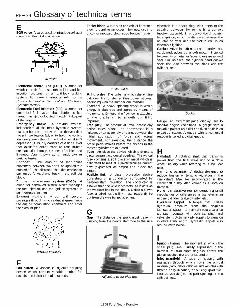
1595 Ford Fiesta Remake
REF•24 Glossary of technical terms
EEGR valve A valve used to introduce exhaustgases into the intake air stream.
Electronic control unit (ECU) A computerwhich controls (for instance) ignition and fuelinjection systems, or an anti-lock brakingsystem. For more information refer to theHaynes Automotive Electrical and ElectronicSystems Manual.Electronic Fuel Injection (EFI) A computercontrolled fuel system that distributes fuelthrough an injector located in each intake portof the engine.Emergency brake A braking system,independent of the main hydraulic system,that can be used to slow or stop the vehicle ifthe primary brakes fail, or to hold the vehiclestationary even though the brake pedal isn’tdepressed. It usually consists of a hand leverthat actuates either front or rear brakesmechanically through a series of cables andlinkages. Also known as a handbrake orparking brake.Endfloat The amount of lengthwisemovement between two parts. As applied to acrankshaft, the distance that the crankshaftcan move forward and back in the cylinderblock.Engine management system (EMS) Acomputer controlled system which managesthe fuel injection and the ignition systems inan integrated fashion.Exhaust manifold A part with severalpassages through which exhaust gases leavethe engine combustion chambers and enterthe exhaust pipe.
FFan clutch A viscous (fluid) drive couplingdevice which permits variable engine fanspeeds in relation to engine speeds.
Feeler blade A thin strip or blade of hardenedsteel, ground to an exact thickness, used tocheck or measure clearances between parts.
Firing order The order in which the enginecylinders fire, or deliver their power strokes,beginning with the number one cylinder.Flywheel A heavy spinning wheel in whichenergy is absorbed and stored by means ofmomentum. On cars, the flywheel is attachedto the crankshaft to smooth out firingimpulses.Free play The amount of travel before anyaction takes place. The “looseness” in alinkage, or an assembly of parts, between theinitial application of force and actualmovement. For example, the distance thebrake pedal moves before the pistons in themaster cylinder are actuated.Fuse An electrical device which protects acircuit against accidental overload. The typicalfuse contains a soft piece of metal which iscalibrated to melt at a predetermined currentflow (expressed as amps) and break thecircuit.Fusible link A circuit protection deviceconsisting of a conductor surrounded byheat-resistant insulation. The conductor issmaller than the wire it protects, so it acts asthe weakest link in the circuit. Unlike a blownfuse, a failed fusible link must frequently becut from the wire for replacement.
GGap The distance the spark must travel injumping from the centre electrode to the side
electrode in a spark plug. Also refers to thespacing between the points in a contactbreaker assembly in a conventional points-type ignition, or to the distance between thereluctor or rotor and the pickup coil in anelectronic ignition.Gasket Any thin, soft material - usually cork,cardboard, asbestos or soft metal - installedbetween two metal surfaces to ensure a goodseal. For instance, the cylinder head gasketseals the joint between the block and thecylinder head.
Gauge An instrument panel display used tomonitor engine conditions. A gauge with amovable pointer on a dial or a fixed scale is ananalogue gauge. A gauge with a numericalreadout is called a digital gauge.
HHalfshaft A rotating shaft that transmitspower from the final drive unit to a drivewheel, usually when referring to a live rearaxle.Harmonic balancer A device designed toreduce torsion or twisting vibration in thecrankshaft. May be incorporated in thecrankshaft pulley. Also known as a vibrationdamper.Hone An abrasive tool for correcting smallirregularities or differences in diameter in anengine cylinder, brake cylinder, etc.Hydraulic tappet A tappet that utiliseshydraulic pressure from the engine’slubrication system to maintain zero clearance(constant contact with both camshaft andvalve stem). Automatically adjusts to variationin valve stem length. Hydraulic tappets alsoreduce valve noise.
IIgnition timing The moment at which thespark plug fires, usually expressed in thenumber of crankshaft degrees before thepiston reaches the top of its stroke.Inlet manifold A tube or housing withpassages through which flows the air-fuelmixture (carburettor vehicles and vehicles withthrottle body injection) or air only (port fuel-injected vehicles) to the port openings in thecylinder head.
Exhaust manifold
Feeler blade
Adjusting spark plug gap
Gasket
EGR valve

1595 Ford Fiesta Remake
Glossary of technical terms REF•25
REF
JJump start Starting the engine of a vehiclewith a discharged or weak battery byattaching jump leads from the weak battery toa charged or helper battery.
LLoad Sensing Proportioning Valve (LSPV) Abrake hydraulic system control valve thatworks like a proportioning valve, but alsotakes into consideration the amount of weightcarried by the rear axle.Locknut A nut used to lock an adjustmentnut, or other threaded component, in place.For example, a locknut is employed to keepthe adjusting nut on the rocker arm inposition.Lockwasher A form of washer designed toprevent an attaching nut from working loose.
MMacPherson strut A type of frontsuspension system devised by EarleMacPherson at Ford of England. In its originalform, a simple lateral link with the anti-roll barcreates the lower control arm. A long strut - anintegral coil spring and shock absorber - ismounted between the body and the steeringknuckle. Many modern so-called MacPhersonstrut systems use a conventional lower A-armand don’t rely on the anti-roll bar for location.Multimeter An electrical test instrument withthe capability to measure voltage, current andresistance.
NNOx Oxides of Nitrogen. A common toxicpollutant emitted by petrol and diesel enginesat higher temperatures.
OOhm The unit of electrical resistance. Onevolt applied to a resistance of one ohm willproduce a current of one amp.Ohmmeter An instrument for measuringelectrical resistance.O-ring A type of sealing ring made of aspecial rubber-like material; in use, the O-ringis compressed into a groove to provide thesealing action.
Overhead cam (ohc) engine An engine withthe camshaft(s) located on top of the cylinderhead(s).Overhead valve (ohv) engine An engine withthe valves located in the cylinder head, butwith the camshaft located in the engine block.Oxygen sensor A device installed in theengine exhaust manifold, which senses theoxygen content in the exhaust and convertsthis information into an electric current. Alsocalled a Lambda sensor.
PPhillips screw A type of screw head having across instead of a slot for a correspondingtype of screwdriver.Plastigage A thin strip of plastic thread,available in different sizes, used for measuringclearances. For example, a strip of Plastigageis laid across a bearing journal. The parts areassembled and dismantled; the width of thecrushed strip indicates the clearance betweenjournal and bearing.
Propeller shaft The long hollow tube withuniversal joints at both ends that carriespower from the transmission to the differentialon front-engined rear wheel drive vehicles.Proportioning valve A hydraulic controlvalve which limits the amount of pressure tothe rear brakes during panic stops to preventwheel lock-up.
RRack-and-pinion steering A steering systemwith a pinion gear on the end of the steeringshaft that mates with a rack (think of a gearedwheel opened up and laid flat). When thesteering wheel is turned, the pinion turns,moving the rack to the left or right. Thismovement is transmitted through the trackrods to the steering arms at the wheels.Radiator A liquid-to-air heat transfer devicedesigned to reduce the temperature of thecoolant in an internal combustion enginecooling system. Refrigerant Any substance used as a heattransfer agent in an air-conditioning system.R-12 has been the principle refrigerant formany years; recently, however, manufacturershave begun using R-134a, a non-CFCsubstance that is considered less harmful to
the ozone in the upper atmosphere.Rocker arm A lever arm that rocks on a shaftor pivots on a stud. In an overhead valveengine, the rocker arm converts the upwardmovement of the pushrod into a downwardmovement to open a valve.Rotor In a distributor, the rotating deviceinside the cap that connects the centreelectrode and the outer terminals as it turns,distributing the high voltage from the coilsecondary winding to the proper spark plug.Also, that part of an alternator which rotatesinside the stator. Also, the rotating assemblyof a turbocharger, including the compressorwheel, shaft and turbine wheel.Runout The amount of wobble (in-and-outmovement) of a gear or wheel as it’s rotated.The amount a shaft rotates “out-of-true.” Theout-of-round condition of a rotating part.
SSealant A liquid or paste used to preventleakage at a joint. Sometimes used inconjunction with a gasket.Sealed beam lamp An older headlight designwhich integrates the reflector, lens andfilaments into a hermetically-sealed one-pieceunit. When a filament burns out or the lenscracks, the entire unit is simply replaced.Serpentine drivebelt A single, long, wideaccessory drivebelt that’s used on somenewer vehicles to drive all the accessories,instead of a series of smaller, shorter belts.Serpentine drivebelts are usually tensioned byan automatic tensioner.
Shim Thin spacer, commonly used to adjustthe clearance or relative positions betweentwo parts. For example, shims inserted into orunder bucket tappets control valveclearances. Clearance is adjusted bychanging the thickness of the shim.Slide hammer A special puller that screwsinto or hooks onto a component such as ashaft or bearing; a heavy sliding handle on theshaft bottoms against the end of the shaft toknock the component free.Sprocket A tooth or projection on theperiphery of a wheel, shaped to engage with achain or drivebelt. Commonly used to refer tothe sprocket wheel itself.Starter inhibitor switch On vehicles with anO-ring
Serpentine drivebelt
Plastigage

1595 Ford Fiesta Remake
REF•26 Glossary of technical termsautomatic transmission, a switch thatprevents starting if the vehicle is not in Neutralor Park.Strut See MacPherson strut.
TTappet A cylindrical component whichtransmits motion from the cam to the valvestem, either directly or via a pushrod androcker arm. Also called a cam follower.Thermostat A heat-controlled valve thatregulates the flow of coolant between thecylinder block and the radiator, so maintainingoptimum engine operating temperature. Athermostat is also used in some air cleaners inwhich the temperature is regulated.Thrust bearing The bearing in the clutchassembly that is moved in to the release leversby clutch pedal action to disengage theclutch. Also referred to as a release bearing.Timing belt A toothed belt which drives thecamshaft. Serious engine damage may resultif it breaks in service.Timing chain A chain which drives thecamshaft.Toe-in The amount the front wheels arecloser together at the front than at the rear. Onrear wheel drive vehicles, a slight amount oftoe-in is usually specified to keep the frontwheels running parallel on the road byoffsetting other forces that tend to spread thewheels apart.Toe-out The amount the front wheels arecloser together at the rear than at the front. On
front wheel drive vehicles, a slight amount oftoe-out is usually specified.Tools For full information on choosing andusing tools, refer to the Haynes AutomotiveTools Manual.Tracer A stripe of a second colour applied toa wire insulator to distinguish that wire fromanother one with the same colour insulator.Tune-up A process of accurate and carefuladjustments and parts replacement to obtainthe best possible engine performance.Turbocharger A centrifugal device, driven byexhaust gases, that pressurises the intake air.Normally used to increase the power outputfrom a given engine displacement, but canalso be used primarily to reduce exhaustemissions (as on VW’s “Umwelt” Dieselengine).
UUniversal joint or U-joint A double-pivotedconnection for transmitting power from adriving to a driven shaft through an angle. A U-joint consists of two Y-shaped yokes and across-shaped member called the spider.
VValve A device through which the flow ofliquid, gas, vacuum, or loose material in bulkmay be started, stopped, or regulated by amovable part that opens, shuts, or partially
obstructs one or more ports or passageways.A valve is also the movable part of such adevice.Valve clearance The clearance between thevalve tip (the end of the valve stem) and therocker arm or tappet. The valve clearance ismeasured when the valve is closed.Vernier caliper A precision measuringinstrument that measures inside and outsidedimensions. Not quite as accurate as amicrometer, but more convenient.Viscosity The thickness of a liquid or itsresistance to flow.Volt A unit for expressing electrical “pressure”in a circuit. One volt that will produce a currentof one ampere through a resistance of oneohm.
WWelding Various processes used to join metalitems by heating the areas to be joined to amolten state and fusing them together. Formore information refer to the HaynesAutomotive Welding Manual.Wiring diagram A drawing portraying thecomponents and wires in a vehicle’s electricalsystem, using standardised symbols. Formore information refer to the HaynesAutomotive Electrical and Electronic SystemsManual.

1595 Ford Fiesta Remake
Index REF•27
REF
Note: References throughout this index relate to Chapter•page number
AAccelerator cable - 4A•4, 4B•4, 4C•4, 4D•3Accelerator pedal - 4A•4, 4B•4, 4C•4, 4D•3Accelerator pump - 4A•8Acknowledgements - 0•4Aerial - 12•16Air bags - 0•5, 12•17Air cleaner - 1•22, 1•23, 4A•3, 4B•4, 4C•3,
4D•3, 4E•5Air temperature control system - 1•23,
4B•8, 4C•7, 4D•6Alarm system - 12•17, REF•5Alternator - 5A•4Anti-lock braking system (ABS) - 9•11,
9•14, 9•16Anti-roll bar - 10•7, 10•11Anti-theft alarm system - 12•17, REF•5Antifreeze - 0•12, 0•17, 1•21, 1•22, 3•2Asbestos - 0•5ATF - 0•17, 1•18, 1•24Automatic choke - 4A•16, 4A•17Automatic transmission - 2A•10, 2B•13,
2C•15, 2D•6, 2D•8, 2D•10, 7B•1 et seq,12•6, 12•8
Automatic transmission fault finding -REF•18
Automatic transmission fluid - 0•17, 1•18,1•24
Auxiliary lights - 12•7, 12•10Axle - 10•10
BBackfire - REF•16Backrest - 11•17Ballast resistor - 4B•9Balljoint - 10•17Battery - 0•5, 0•14, 5A•2, 5A•3Battery fault - REF•20Big-end bearings - 2D•21, 2D•24Bleeding braking system - 9•10, 9•11Bleeding power steering - 10•17Body electrical systems - 1•18, 12•1 et seq,
REF•11Body electrical system fault finding - 5A•2,
12•3, REF•20Bodywork and fittings - 1•18, 11•1 et seq,
REF•13Bonnet - 1•18, 11•4, 11•5Boot - 1•16Boots - 8•3, 8•4, 10•15Brake fluid - 0•13, 0•17, 1•26, 12•6Braking system - 1•17, 9•1 et seq, 12•6,
REF•10, REF•11, REF•12Braking system fault finding - REF•18
Bulbs - 0•16, 12•7, 12•8Bumpers - 11•7, 11•8Burning - 0•5Buying spare parts - REF•5
CCables - 4A•4, 4B•4, 4C•4, 4D•3, 6•1, 7B•2,
9•12, 9•13, 12•12Calipers - 9•3Camshaft - 2B•6, 2B•7, 2C•7, 2C•8, 2D•16Camshaft position sensor - 4D•6Carburettor - 4A•7, 4A•8, 4A•9, 4A•11,
4A•13, 4A•14, 4A•15, 4A•17, 4A•18Carpets - 11•2Cassette player - 12•15, REF•5Catalytic converter - 4E•2, 4E•5Centre console - 11•20, 12•5Charcoal canister - 4E•6Charging system - 5A•3Choke - 4A•4, 4A•16, 4A•17Cigarette lighter - 12•9, 12•12Clock - 12•8, 12•12Clutch - 1•18, 6•1 et seqClutch fault finding - REF•17Coil - 5B•4Compression test - 2A•3, 2B•3, 2C•3Connecting rods - 2D•17, 2D•24, 2D•25Console - 11•20, 12•5Contents - 0•2Conversion factors - REF•6Coolant - 0•12, 0•17, 1•21, 1•22, 3•2Coolant pump - 3•7Coolant temperature sensor - 4B•8, 4C•7,
4D•6Cooling, heating and ventilation systems -
3•1 et seqCooling system fault finding - REF•16Courtesy light - 12•6, 12•9Crankcase - 2D•19Crankcase ventilation system - 1•24Crankshaft - 2A•6, 2A•9, 2B•4, 2B•6,
2B•12, 2C•4, 2C•7, 2C•14, 2D•18,2D•22, 2D•24
Crankshaft position sensor - 4B•8, 4C•7,4D•6, 5B•5
Crossmember - 10•7Crushing - 0•5Cushion - 11•17CV joint - 1•16, 8•3, 8•4CVH and PTE engine in-car repair
procedures - 2B•1 et seqCylinder block - 2D•19Cylinder head - 2A•4, 2A•5, 2B•4, 2B•9,
2C•3, 2C•10, 2D•12, 2D•14, 2D•15
DDents in bodywork - 11•2Depressurising fuel system - 4B•3, 4C•3,
4D•2Differential - 7A•3, 7B•3Dimensions - REF•1Direction indicators - 12•7, 12•9, 12•10Discs - 9•4Distributor - 1•20, 5B•5, 5B•6, 5B•7Doors - 1•18, 11•6, 11•9, 11•10,,11•11,
11•13, 11•14, 11•15, REF•11Drip rail moulding - 11•5Drivebelt - 1•11Driveplate - 2B•14, 2C•16Driveshafts - 1•16, 8•1 et seq, REF•12Driveshafts fault finding - REF•19Drivetrain - 1•18Drums - 9•4
EEarth fault - 12•4EEC IV engine management module - 4C•6Electric shock - 0•5Electric windows - 11•14, 12•7, 12•15,
REF•20Emblems - 11•5Emission control system - 1•24, 4E•1Engine fault finding - REF•15, REF•16,
REF•18Engine oil - 0•12, 0•17, 1•9Engine removal and overhaul procedures -
2D•1 et seqEnvironmental considerations - REF•4Evaporative emission control systems -
1•24, 4E•2, 4E•5Exhaust and emission control systems -
4E•1 et seqExhaust emission checks - REF•13Exhaust manifold - 4E•3Exhaust system - 1•16, 4E•1, 4E•2, REF•5,
REF•12Exhaust system fault - REF•17Expansion tank - 3•6
FFacia - 11•20, 12•5Fan - 3•4Fast-idle speed adjustment - 4A•13, 4A•15,
4A•9, 4A•7Fault finding - REF•14 et seqFault finding - automatic transmission -
REF•18Fault finding - braking system - REF•18

Fault finding - clutch - REF•17Fault finding - cooling system - REF•16Fault finding - driveshafts - REF•19Fault finding - electrical system - 5A•2,
12•3, REF•20Fault finding - engine - REF•15, REF•16,
REF•18Fault finding - fuel and exhaust systems -
REF•17Fault finding - manual transmission -
REF•17Fault finding - suspension and steering
systems - REF•19Filling - 11•3Filter, air - 1•22, 1•23, 4A•3, 4B•4, 4C•3,
4D•3, 4E•5Filter, oil - 1•9Filter, fuel - 1•25Fire - 0•5Float - 4A•7, 4A•9, 4A•16Fluid seals - 7B•3Fluids - 0•17Flywheel - 2A•11, 2B•14, 2C•16Fuel consumption high - REF•17Fuel cut-off switch - 4B•5, 4C•5, 4D•4Fuel filler pipe - 4A•6, 4B•5, 4C•5, 4D•4Fuel filter - 1•25Fuel gauge - 4A•6, 4B•4, 4C•5, 4D•4, 12•12Fuel gauge fault - REF•20Fuel hoses - 1•13Fuel injectors - 4B•5, 4C•5, 4D•5Fuel lines - 1•17, 4B•3, 4C•3, 4D•2Fuel pressure check - 4C•4Fuel pressure regulator - 4B•6, 4C•6, 4D•5Fuel pump - 4A•5, 4B•4, 4C•4, 4C•5, 4D•4Fuel rail - 4C•5, 4D•5Fuel system - carburettor engines - 4A•1 et
seqFuel system - central fuel injection engines
- 4B•1 et seqFuel system - electronic fuel injection
engines - 4C•1 et seqFuel system - sequential electronic fuel
injection engines - 4D•1 et seqFuel and exhaust systems - REF•13Fuel and exhaust systems fault finding -
REF•17Fuel tank - 4A•5, 4A•6, 4B•4, 4B•5, 4C•5,
4D•4Fuel trap - 4B•7Fume or gas intoxication - 0•5Fuses - 0•16, 12•4
GGaiters - 1•16, 8•3, 8•4, 10•15Gashes in bodywork - 11•3Gaskets - REF•4Gear lever - 7A•2Gear selection problems - REF•18Gear selector - 7B•2Gearbox oil - 0•17, 1•14Gearbox - See Manual gearboxGearchange linkage - 7A•2Gearchange selector - 7A•3Glossary of technical terms - REF•22 et seqGrab handle - 11•20
HHandbrake - 1•25, 9•12, 9•13, 12•6,
REF•10Handles - 11•11, 11•13, 11•20Hazard warning switch - 12•8HC emissions - REF•13HCS engine in-car repair procedures -
2A•1 et seqHeadlight - 12•7, 12•9, 12•10Heater - 3•2, 3•8, 12•6, 12•9Horn - 12•12Horn fault - REF•20HT lead - 1•20Hub bearings - 10•5, 10•8, REF•12Hydraulic pipes and hoses - 9•9Hydraulic tappets - 2C•8Hydrofluoric acid - 0•5
IIdle speed - 1•14, 1•15, 1•20, 4C•6Idle speed control valve - 4D•6Idling fault - REF•15Ignition amplifier - 5B•5Ignition switch - 12•5Ignition system - 5B•1 et seqIgnition fault - REF•20Ignition timing - 5B•7Indicators - 12•7, 12•9, 12•10Injector ballast resistor - 4B•9Injectors - 4C•5, 4D•5Inlet manifold - 4A•18, 4B•9, 4C•8, 4D•7Instruments - 1•18, 12•8, 12•11Instrument fault - REF•20Intercooler - 4C•8Interior light - 12•6, 12•9
JJacking and vehicle support - REF•5Joint mating faces - REF•4Joystick - 12•16Jump starting - 0•7
LLeaks - 0•9, 1•12, REF•16, REF•17, REF•18,
REF•20Light-laden valve - 9•13, 9•14Lighter - 12•9, 12•12Lights-on warning module - 12•16Load compartment - 11•20Load-apportioning valve - 9•16Locknuts, locktabs and washers - REF•4Locks - 11•11, 11•12, 11•13, 12•5Loudspeaker housing - 11•20Lower arm - 10•8Lubricants - 0•17Luggage area - 12•6, 12•9
MMain bearings - 2D•21, 2D•22Manifold absolute pressure sensor - 4B•8,
4C•7
Manifolds - 4A•18, 4B•9, 4C•8, 4D•7, 4E•3Manual gearbox Manual transmission - 2A•10, 2B•13,
2C•15, 2D•6, 2D•8, 2D•10, 7A•1 et seqManual transmission fault finding - REF•17Manual transmission oil - 0•17, 1•14Mass air flow sensor - 4D•6Master cylinder - 9•7Minor scratches in bodywork - 11•2Mirrors - 11•8, 11•9, REF•10Misfire - REF•15Mixture - 1•14, 1•15, 4C•7, REF•13Modulator - 9•16MOT test checks - REF•10 et seqMountings - 2A•10, 2B•13, 2C•15
NNeedle valve - 4A•7, 4A•9, 4A•16Number plate light - 12•8, 12•10
OOil filter - 1•9Oil pressure fault - REF•16Oil pump - 2A•8, 2A•9, 2B•11, 2B•12,
2C•13Oil seals - 2A•9, 2B•7, 2B•12, 2C•8, 2C•14,
7A•3, 7B•3, REF•4Oil separator - 4E•5Oil, engine - 0•12, 0•17, 1•9Oil, manual transmission - 0•17, 1•14Open-circuit - 12•4Overcooling - REF•16Overheating - REF•16Oxygen sensor - 4B•8, 4C•7, 4D•7
PPads - 9•2Paint - 1•18Parcel shelf - 11•20Parking light - 12•7Passive Anti-Theft System (PATS) - 12•17Pedals - 4A•4, 4B•4, 4C•4, 4D•3, 6•2, 9•8,
9•9Pinking - REF•16Piston rings - 2D•22Pistons - 2D•17, 2D•24, 2D•25Plastic components - 11•4Poisonous or irritant substances - 0•5Positive crankcase ventilation system -
4E•1, 4E•5Power steering - 10•14, 10•15, 10•16,
10•17Power steering fluid - 0•13, 0•17Power steering pressure switch - 4B•8,
4C•7, 4D•7Pre-ignition - REF•16Printed circuit - 12•11Pulse-air system - 4E•2, 4E•6, 4E•7
QQuarter mouldings - 11•8
REF•28 Index
1595 Ford Fiesta Remake

RRadiator - 3•6Radiator fan - 3•4Radiator grille - 11•7Radio - 12•15, REF•5Rear axle - 10•10Rear light cluster - 12•7, 12•8, 12•10Regulator (window) - 11•14Relays - 12•4Release bearing - 6•4Repair procedures - REF•4Respraying - 11•3Reversing light - 7A•4, 12•6Ride height - 10•12Road test - 1•18Roadside repairs - 0•6 et seqRoadwheels - 1•15, 1•16, 1•17Rocker arms - 2B•7Rocker cover - 2B•4Rocker gear - 2A•4Roof drip rail moulding - 11•5Rotor arm - 1•20, 5B•5Routine maintenance and servicing - 1•1
et seqRoutine maintenance - bodywork and
underframe - 11•2Routine maintenance - upholstery and
carpets - 11•2Rubber boots - 1•16, 8•3, 8•4, 10•15Rust holes in bodywork - 11•3
SSafety first - 0•5Scalding - 0•5Screw threads and fastenings - REF•4Seat belts - 1•18, 11•17, REF•11Seats - 11•17, REF•11Selector - 7B•2, 12•8Servo - 9•9, 9•11, 9•12Shock absorbers - 10•11, REF•11, REF•12Shoes - 9•5Short-circuit - 12•4Sidelight - 12•7Sill moulding - 11•6Sill scuff plate - 11•19Spark plug - 1•19Speakers - 12•16
Speedometer - 7A•3, 7B•3, 12•11, 12•12Spoiler - 11•12Springs - REF•12Starter inhibitor switch - 7B•4, 12•6Starter motor - 5A•7Starter motor fault - REF•15Starting and charging systems - 5A•1 et
seqSteering - See Suspension and steeringStop-light switch - 12•6Struts - 10•6, 10•9Sump - 2A•7, 2B•10, 2C•12Sunroof - 11•16Suspension and steering - 1•15, 1•18, 10•1
et seq, 12•5, REF•10, REF•11, REF•12Suspension and steering fault finding -
REF•19Switches - 3•5, 4B•5, 4B•8, 4C•5, 4C•7,
4D•4, 4D•7, 7A•4, 7B•4, 9•16, 12•5
TTachometer - 12•12Tailgate - 1•18, 11•12, 11•16, 12•15, 2B•7,
2C•8, 2D•16Temperature gauge - 3•5, 12•12Temperature gauge fault - REF•20Thermostat - 3•3Throttle housing - 4C•6, 4D•4Throttle kicker unit - 4A•10, 4A•11,
4A•13Throttle plate control motor - 4B•7Throttle position sensor - 4B•8, 4C•7,
4D•6Timing - 5B•7Timing belt - 1•25, 2B•5, 2B•6, 2C•5, 2C•7Timing chain - 2A•6, 2A•7Tools - REF•4, REF•7, REF•9Top Dead Centre (TDC) for No 1 piston -
2A•3, 2B•3, 2C•3Towing - 0•9Track rod end - 10•17Trim - 1•18Trim panels - 11•5, 11•6, 11•8, 11•10,
11•12, 11•13, 11•19, 11•20Turbocharger - 4C•8, 4C•9Tyres - 0•15, REF•5, REF•13Tyre fault - REF•19Tyre pressures - 0•18
UUnderbody - 1•17Underframe - 11•2Upholstery - 11•2
VVacuum hoses - 1•13Vacuum servo - 9•9, 9•11, 9•12Valve clearance - 1•14, 2A•4, 2B•4, 2C•4Valves - 2D•14, 2D•15Vehicle identification - REF•3, REF•11Vehicle speed sensor - 4B•8, 4C•7, 4D•7Vehicle support - REF•5Ventilation components - 3•2, 3•8Voltage regulator - 5A•4
WWarning lights - 12•8, 12•11Washer system - 0•14, 12•14, 12•15Washers fault - REF•20Water pump - 3•7Weatherseal - 11•6, 11•16Weekly checks - 0•10 et seqWeights - REF•2Wheel alignment - 1•25, 10•17Wheel bearings - 10•5, 10•8, REF•12Wheel changing - 0•8Wheel cylinders - 9•6Wheelarch liners - 11•6Wheels - REF•13Wheels locking - REF•18Wind deflector - 11•7Windows - 11•14, 11•15, 12•7, 12•15,
REF•20Windscreen - 11•16, REF•10Wipers - 0•16, 12•12, 12•13, 12•14Wipers fault - REF•20Wiring check - 1•13Wiring diagrams - 12•19 et seqWorking facilities - REF•9
ZZetec engine in-car repair procedures -
2C•1 et seq
Index REF•29
REF
1595 Ford Fiesta Remake

1595 Ford Fiesta Remake
Left blank formanual listing
pages

1595 Ford Fiesta Remake
REF
Left blank formanual listing
pages

1595 Ford Fiesta Remake
Almost every car you’ve ever loved, loathed or desired is gathered under one roof at the Haynes MotorMuseum. Over 300 immaculately presented cars and motorbikes represent every aspect of our motoring
heritage, from elegant reminders of bygone days, such as the superb Model J Duesenberg to curiosities likethe bug-eyed BMW Isetta. There are also many old friends and flames. Perhaps you remember the 1959 Ford
Popular that you did your courting in? The magnificent ‘Red Collection’ is a spectacle of classic sports carsincluding AC, Alfa Romeo, Austin Healey, Ferrari, Lamborghini, Maserati, MG, Riley, Porsche and Triumph.
A Perfect Day OutEach and every vehicle at the Haynes Motor Museum has played its part in the history and culture of
Motoring. Today, they make a wonderful spectacle and a great day out for all the family. Bring the kids, bringMum and Dad, but above all bring your camera to capture those golden memories for ever. You will also find
an impressive array of motoring memorabilia, a comfortable 70 seat video cinema and one of the mostextensive transport book shops in Britain. The Pit Stop Cafe serves everything from a cup of tea to
wholesome, home-made meals or, if you prefer, you can enjoy the large picnic area nestled in the beautifulrural surroundings of Somerset.
The Museum is situated on the A359 Yeovil to Frome road at Sparkford, just off the A303 in Somerset. It is about 40 miles south of Bristol, and 25 minutes drive from the M5 intersection at Taunton.
Open 9.30am - 5.30pm (10.00am - 4.00pm Winter) 7 days a week, except Christmas Day, Boxing Day and New Years DaySpecial rates available for schools, coach parties and outings Charitable Trust No. 292048
>John Haynes O.B.E.,
Founder andChairman of the
museum at the wheelof a Haynes Light 12.
<Graham Hill’s LolaCosworth Formula 1car next to a 1934Riley Sports.
<The Model J DuesenbergDerham Tourster. Only eight of thesemagnificent cars wereever built – this is theonly example to be foundoutside the UnitedStates of America
Preserving Our Motoring Heritage