router / shaper - best woodworking tools€¦ · for the router/shaper warning: failure to follow...
TRANSCRIPT

INS
TRU
CTIO
NM
AN
UA
LRouter / Shaper
(Model SH100)
PART NO. 905582 - 05-15-02Copyright © 2002 Delta Machinery
ESPAÑOL: PÁGINA 19To learn more about DELTA MACHINERY visit our website at: www.deltamachinery.com.For Parts, Service, Warranty or other Assistance,
please call 1-800-223-7278 (In Canada call 1-800-463-3582).

2
GENERAL SAFETY RULESWoodworking can be dangerous if safe and proper operating procedures are not followed. As with all machinery, thereare certain hazards involved with the operation of the product. Using the machine with respect and caution willconsiderably lessen the possibility of personal injury. However, if normal safety precautions are overlooked or ignored,personal injury to the operator may result. Safety equipment such as guards, push sticks, hold-downs, featherboards,goggles, dust masks and hearing protection can reduce your potential for injury. But even the best guard won’t makeup for poor judgment, carelessness or inattention. Always use common sense and exercise caution in the workshop.If a procedure feels dangerous, don’t try it. Figure out an alternative procedure that feels safer. REMEMBER: Yourpersonal safety is your responsibility.
This machine was designed for certain applications only. Delta Machinery strongly recommends that this machine notbe modified and/or used for any application other than that for which it was designed. If you have any questions relativeto a particular application, DO NOT use the machine until you have first contacted Delta to determine if it can or shouldbe performed on the product.
Technical Service ManagerDelta Machinery4825 Highway 45 NorthJackson, TN 38305
(IN CANADA: 505 SOUTHGATE DRIVE, GUELPH, ONTARIO N1H 6M7)
WARNING: FAILURE TO FOLLOW THESE RULES MAY RESULT IN SERIOUS PERSONAL INJURY
1. FOR YOUR OWN SAFETY, READ INSTRUCTIONMANUAL BEFORE OPERATING THE TOOL. Learn thetool’s application and limitations as well as the specifichazards peculiar to it.
2. KEEP GUARDS IN PLACE and in working order.3. ALWAYS WEAR EYE PROTECTION. Wear safety
glasses. Everyday eyeglasses only have impact resistantlenses; they are not safety glasses. Also use face or dustmask if cutting operation is dusty. These safety glassesmust conform to ANSI Z87.1 requirements. NOTE:Approved glasses have Z87 printed or stamped on them.
4. REMOVE ADJUSTING KEYS AND WRENCHES. Formhabit of checking to see that keys and adjusting wrenchesare removed from tool before turning it “on”.
5. KEEP WORK AREA CLEAN. Cluttered areas andbenches invite accidents.
6. DON’T USE IN DANGEROUS ENVIRONMENT. Don’tuse power tools in damp or wet locations, or expose themto rain. Keep work area well-lighted.
7. KEEP CHILDREN AND VISITORS AWAY. All childrenand visitors should be kept a safe distance from work area.
8. MAKE WORKSHOP CHILDPROOF – with padlocks,master switches, or by removing starter keys.
9. DON’T FORCE TOOL. It will do the job better and besafer at the rate for which it was designed.10. USE RIGHT TOOL. Don’t force tool or attachment todo a job for which it was not designed.11. WEAR PROPER APPAREL. No loose clothing, gloves,neckties, rings, bracelets, or other jewelry to get caught inmoving parts. Nonslip footwear is recommended. Wearprotective hair covering to contain long hair.12. SECURE WORK. Use clamps or a vise to hold workwhen practical. It’s safer than using your hand and freesboth hands to operate tool.13. DON’T OVERREACH . Keep proper footing andbalance at all times.14. MAINTAIN TOOLS IN TOP CONDITION. Keep toolssharp and clean for best and safest performance. Followinstructions for lubricating and changing accessories.15. DISCONNECT TOOLS before servicing and whenchanging accessories such as blades, bits, cutters, etc.16. USE RECOMMENDED ACCESSORIES. The use ofaccessories and attachments not recommended by Deltamay cause hazards or risk of injury to persons.17. REDUCE THE RISK OF UNINTENTIONAL STARTING.Make sure switch is in “OFF” position before plugging inpower cord. In the event of a power failure, move switchto the “OFF” position.
18. NEVER STAND ON TOOL. Serious injury could occur ifthe tool is tipped or if the cutting tool is accidentallycontacted.19. CHECK DAMAGED PARTS. Before further use of thetool, a guard or other part that is damaged should becarefully checked to ensure that it will operate properly andperform its intended function – check for alignment ofmoving parts, binding of moving parts, breakage of parts,mounting, and any other conditions that may affect itsoperation. A guard or other part that is damaged should beproperly repaired or replaced.20. DIRECTION OF FEED. Feed work into a blade orcutter against the direction of rotation of the blade or cutteronly.21. NEVER LEAVE TOOL RUNNING UNATTENDED.TURN POWER OFF. Don’t leave tool until it comes to acomplete stop.22. STAY ALERT, WATCH WHAT YOU ARE DOING, ANDUSE COMMON SENSE WHEN OPERATING A POWERTOOL. DO NOT USE TOOL WHILE TIRED OR UNDERTHE INFLUENCE OF DRUGS, ALCOHOL, ORMEDICATION. A moment of inattention while operatingpower tools may result in serious personal injury.23. MAKE SURE TOOL IS DISCONNECTED FROMPOWER SUPPLY whi le motor is be ing mounted,connected or reconnected.24. THE DUST GENERATED by certain woods and woodproducts can be injurious to your health. Always operatemachinery in well ventilated areas and provide for properdust removal. Use wood dust collection systems wheneverpossible.25. WARNING: SOME DUST CREATED BYPOWER SANDING, SAWING, GRINDING, DRILLING,AND OTHER CONSTRUCTION ACTIVITIES containschemicals known to cause cancer, birth defects or otherreproductive harm. Some examples of these chemicalsare:· lead from lead-based paints,· crystalline silica from bricks and cement and other
masonry products, and· arsenic and chromium from chemically-treated lumber. Your risk from these exposures varies, depending on howoften you do this type of work. To reduce your exposureto these chemicals: work in a well ventilated area, andwork with approved safety equipment, such as thosedust masks that are specially designed to filter outmicroscopic particles.
SAVE THESE INSTRUCTIONS. Refer to them often and use them to instruct others.

3
ADDITIONAL SAFETY RULES FORFOR THE ROUTER/SHAPER
WARNING: FAILURE TO FOLLOW THESE RULES MAY RESULT IN SERIOUS PERSONAL INJURY
Fig. B
21. USE A HEAVY WORKPIECE when shaping withstarting pin and collar(s). DO NOT SHAPE a short,light workpiece against the collar(s) (Figs. D and E).
Fig. D
Fig. E
Fig. F
SUFFICIENTBEARING SURFACE
CUTTERCOLLAR
RIGHT
CUTTER
COLLARRIGHT
CUTTERCOLLAR
WRONG
CUTTERCOLLAR WORK
TABLE
22. POSITION THE CUTTER below the collar(s) whenshaping with starting pin and collar(s) (Fig. F).
1. DO NOT OPERATE THIS MACHINE UNTIL it isassembled and installed according to theinstructions.
2. OBTAIN ADVICE from your supervisor, instructor,or another qualified person if you are not familiarwith the operation of this machine.
3. FOLLOW ALL WIRING CODES and recommendedelectrical connections.
4. NEVER turn the machine “ON” before clearing thetable of all objects (tools, scraps of wood, etc.).
5. AVOID awkward hand positions. A sudden slipcould allow the hand to contact the cutter.
6. KEEP hands away from cutter.7. NEVER START THE MACHINE with the workpiece
contacting the cutter.8. NEVER reach under the table while the machine is
running.9. KEEP cutters sharp and free from rust and pitch.10. NEVER ADJUST THE FENCE while the machine is
running.11. ADJUST THE FENCE HALVES so that the cutter
opening is never more than is required to clear thecutter.
12. LOCK THE FENCE HARDWARE after making fenceadjustments.
13. PROPERLY SECURE THE CUTTERS beforestarting the machine.
14. DO NOT perform any operation freehand. Use thefence for straight shaping, the miter gauge for edgeshaping, and the starting pin and rub collars forcurve shaping.
15. KEEP THE FRONT MOTOR ACCESS PANELCLOSED while operating the machine.
16. USE GUARDS provided with the machine.17. DO NOT feed a workpiece that is warped, contains
knots, or is embedded with foreign objects, (nails,staples, etc.).
18. NEVER run the workpiece between the fence andthe cutter.
19. USE A MITER GAUGE and a clamp attachmentwhen edge shaping work less than 3" wide. Removethe fence during this operation.
20. PROVIDE SUFFICIENT BEARING surface whenshaping with a starting pin and collar(s) (Figs. B andC).
24. NEVER PERFORM LAYOUT, assembly, or set-upwork on the table while the machine is running.
25. TURN THE MACHINE “OFF” AND DISCONNECTTHE MACHINE from the power source beforeinstalling or removing accessories, before adjustingor changing set-ups, or when making repairs.
26. TURN THE MACHINE “OFF”, disconnect themachine from the power source, and clean thetable/work area before leaving the machine. LOCKTHE SWITCH IN THE “OFF” POSITION to preventunauthorized use.
27. ADDITIONAL INFORMATION regarding the safeand proper operation of this machine is availablefrom the Power Tool Institute, 1300 SummerAvenue, Cleveland, OH 44115-2851. Information isalso available from the National Safety Council,1121 Spring Lake Drive, Itasca, IL 60143-3201.Please refer to the American National StandardsInstitute ANSI 01.1 Safety Requirements forWoodworking Machines and the U.S. Departmentof Labor OSHA 1910.213 Regulations.
Fig. G
CUTTER ROTATION
FEED
Fig. C
INSUFFICIENTBEARING SURFACE
CUTTER
COLLAR
WRONG
23. FEED WORKPIECE against cutter rotation (Fig. G).
SAVE THESE INSTRUCTIONS.
Refer to them often
and use them to instruct others.

4
POWER CONNECTIONSA separate electrical circuit should be used for your machines. This circuit should not be less than #12 wire and shouldbe protected with a 20 Amp time lag fuse. If an extension cord is used, use only 3-wire extension cords which have 3-prong grounding type plugs and matching receptacle which will accept the machine’s plug. Before connecting themotor to the power line, make sure the switch is in the “OFF” position and be sure that the electric current is of thesame characteristics as indicated on the machine. All line connections should make good contact. Running on lowvoltage will damage the motor.
WARNING: DO NOT EXPOSE THE MACHINE TO RAIN OR OPERATE THE MACHINE IN DAMP LOCATIONS.
MOTOR SPECIFICATIONSYour machine is wired for 120 volt, 60 HZ alternating current. Before connecting the machine to the power source,make sure the switch is in the “OFF” position.
GROUNDING INSTRUCTIONSWARNING: THIS MACHINE MUST BE GROUNDED WHILE IN USE TO PROTECT THE OPERATOR FROMELECTRIC SHOCK.
Fig. A Fig. B
GROUNDED OUTLET BOX
CURRENTCARRYING
PRONGS
GROUNDING BLADEIS LONGEST OF THE 3 BLADES
GROUNDED OUTLET BOX
GROUNDINGMEANS
ADAPTER
2. Grounded, cord-connected machines intended for useon a supply circuit having a nominal rating less than 150volts:
If the machine is intended for use on a circuit that has anoutlet that looks like the one illustrated in Fig. A, themachine will have a grounding plug that looks like the plugillustrated in Fig. A. A temporary adapter, which looks likethe adapter illustrated in Fig. B, may be used to connectthis plug to a matching 2-conductor receptacle as shownin Fig. B if a properly grounded outlet is not available. Thetemporary adapter should be used only until a properlygrounded outlet can be installed by a qualified electrician.The green-colored rigid ear, lug, and the like, extendingfrom the adapter must be connected to a permanentground such as a properly grounded outlet box. Wheneverthe adapter is used, it must be held in place with a metalscrew.
NOTE: In Canada, the use of a temporary adapter is notpermitted by the Canadian Electric Code.
WARNING: IN ALL CASES, MAKE CERTAIN THE RECEPTACLE IN QUESTION IS PROPERLY
GROUNDED. IF YOU ARE NOT SURE HAVE AQUALIFIED ELECTRICIAN CHECK THE RECEPTACLE.
1. All grounded, cord-connected machines:
In the event of a malfunction or breakdown, groundingprovides a path of least resistance for electric current toreduce the risk of electric shock. This machine isequipped with an electric cord having an equipment-grounding conductor and a grounding plug. The plug mustbe plugged into a matching outlet that is properly installedand grounded in accordance with all local codes andordinances.
Do not modify the plug provided - if it will not fit the outlet,have the proper outlet installed by a qualified electrician.
Improper connection of the equipment-groundingconductor can result in risk of electric shock. Theconductor with insulation having an outer surface that isgreen with or without yellow stripes is the equipment-grounding conductor. If repair or replacement of theelectric cord or plug is necessary, do not connect theequipment-grounding conductor to a live terminal.
Check with a qualified electrician or service personnel ifthe grounding inst ruct ions are not complete lyunderstood, or if in doubt as to whether the machine isproperly grounded.
Use only 3-wire extension cords that have 3-pronggrounding type plugs and matching 3-conductorreceptacles that accept the machine’s plug, as shown inFig. A.
Repair or replace damaged or worn cord immediately.

Use proper extension cords. Make sure your extension cord is in good condition and is a 3-wire extension cord whichhas a 3-prong grounding type plug and matching receptacle which will accept the machine’s plug. When using anextension cord, be sure to use one heavy enough to carry the current of the machine. An undersized cord will cause adrop in line voltage, resulting in loss of power and overheating. Fig. D, shows the correct gauge to use depending onthe cord length. If in doubt, use the next heavier gauge. The smaller the gauge number, the heavier the cord.
EXTENSION CORDS
OPERATING INSTRUCTIONSFOREWORD
Delta ShopMaster Model SH100 Router / Shaper is an economical alternative to the production wood shaper. The Router/ Shaper has a powerful, 9 amp, induction-type, ball bearing motor for long-lasting trouble free operation. The Router /Shaper also has a thermal overload protection which prevents motor overload.
UNPACKING AND CLEANINGCarefully unpack the machine and all loose items from the shipping container(s). Remove the protective coating fromall unpainted surfaces. This coating may be removed with a soft cloth moistened with kerosene (do not use acetone,gasoline or lacquer thinner for this purpose). After cleaning, cover the unpainted surfaces with a good quality householdfloor paste wax.
NOTICE: THE MANUAL COVER PHOTO ILLUSTRATES THE CURRENTPRODUCTION MODEL. ALL OTHER ILLUSTRATIONS ARE REPRESENTATIVE
ONLY AND MAY NOT DEPICT THE ACTUAL COLOR, LABELING ORACCESSORIES AND MAY BE INTENDED TO ILLUSTRATE TECHNIQUE ONLY.
5
Fig. D
MINIMUM GAUGE EXTENSION CORDRECOMMENDED SIZES FOR USE WITH STATIONARY ELECTRIC MACHINES
Ampere Total Length Gauge ofRating Volts of Cord in Feet Extension Cord
0-6 120 up to 25 18 AWG0-6 120 25-50 16 AWG0-6 120 50-100 16 AWG0-6 120 100-150 14 AWG
6-10 120 up to 25 18 AWG6-10 120 25-50 16 AWG6-10 120 50-100 14 AWG6-10 120 100-150 12 AWG
10-12 120 up to 25 16 AWG10-12 120 25-50 16 AWG10-12 120 50-100 14 AWG10-12 120 100-150 12 AWG
12-16 120 up to 25 14 AWG12-16 120 25-50 12 AWG12-16 120 GREATER THAN 50 FEET NOT RECOMMENDED

6
ROUTER / SHAPER PARTS
Fig. 2
1. Router / Shaper2. 1¼" Open End Arbor Wrench3. Collet Wrench4. 3mm Hex wrench5. Left Hand Fence Body6. Right Hand Fence Assembly7. Spindle Knob8. Fence Knob (2)9. Cutter Guard Bracket10. Template Guide Insert11. Wooden Fence (2)12. 1/2" Collet with Nut13. 1/4" Adapter
14. Foot (4)15. Pin16. Overhead Cutter Guard17. Dust Chute18. Dust Hood19. 3/8-16x1½" Pan Head Screw (2)20. 5/16-18x1¼" Carriage Head Bot (2)21. M6x1x10mm Cheese Head Screw (2)22. M5x.8x10mm Cheese Head Screw (2)23. M4x.7x8mm Cheese Head Screw (2)24. M6x1x8mm Set Screw (1)25. 3/8-16 Hex Nut (2)26. 5/16" Flat Washer (2)
1
2 3
4
5
67 8
9
10
11
12 13
14 15
16
17
18
19
20
21
22
23
24
25
26
7
ASSEMBLYWARNING: FOR YOUR OWN SAFETY, DO NOT CONNECT THE MACHINE TO THE POWER SOURCE UNTIL
THE MACHINE IS COMPLETELY ASSEMBLED. DO NOT OPERATE THIS MACHINE UNTIL YOU READ ANDUNDERSTAND THE ENTIRE INSTRUCTION MANUAL
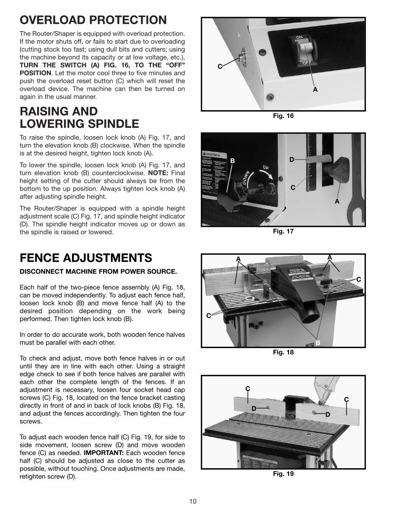
OVERHEAD CUTTER GUARDBRACKETAssemble the overhead cutter guard holding bracket (A)Fig. 6, to the rear of the Router/Shaper and fasten withthe two M6x10mm cheese head screws (B).
Fig. 6
AB B
Fig. 5
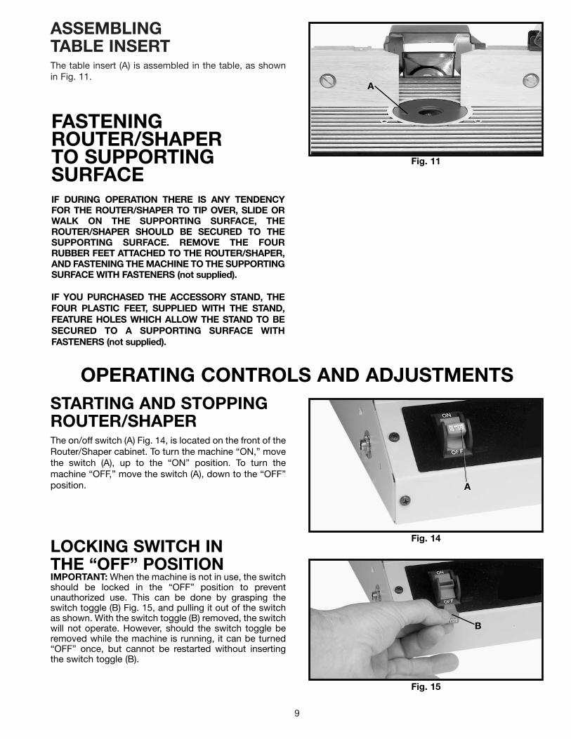
SPINDLE RAISING ANDLOWERING HANDLE1. Assemble handle (A) Fig. 5, to shaft (B) making surethe flat on inside of handle lines up with flat on shaft.
2. Fasten handle (A) Fig. 5, to shaft using a M6x1x8mmset screw (C), with the 3mm hex wrench supplied.
AB
C
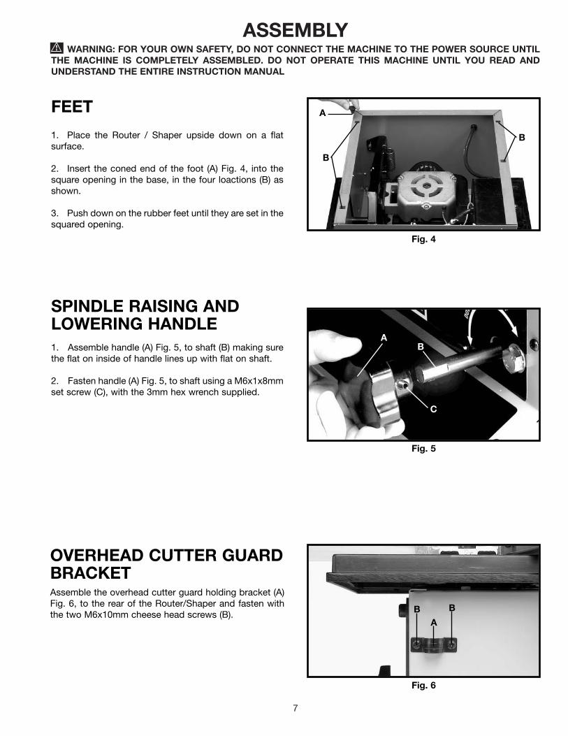
FEET
1. Place the Router / Shaper upside down on a flatsurface.
2. Insert the coned end of the foot (A) Fig. 4, into thesquare opening in the base, in the four loactions (B) asshown.
3. Push down on the rubber feet until they are set in thesquared opening.
Fig. 4
A
B
B

8
Fig. 10
P
S
A
H
FENCE ASSEMBLY ANDDUST CHUTETwo fence halves are supplied as standard equipmentwith the Router/Shaper. To assemble and install thefence assembly, proceed as follows:
1. NOTE: The fence body with the see-thru cutterguard (R) Fig. 7, assembled to it, is to be assembled tothe right hand side of the table, when facing the front ofthe machine. (Note: Fig. 7 is shown from the rear ofthe machine for clarity.) Place keyed bottom portion ofthe left hand fence body (A) Fig. 7, in table slot (B). Inserta 5/16-18x1-1/4" carriage head bolt (C) up throughbottom of table slot (B), place a 5/16" flat washer on boltand secure with fence knob (D).
2. Place back of wooden fence (E) Fig. 7, against frontof fence body (A), as shown. Line up hole in woodenfence (E) with slot (F) in fence body (A) and fastenwooden fence (E) to fence body by inserting a 3/8-16x1-1/2" screw through hole in wooden fence and hole infence body thread a 3/8-16 hex nut (G) onto the 3/8-16x1-1/2" screw.
3. Assemble the right hand fence assembly (T) Fig. 7,to the table in the same manner.
4. If you will be connecting your Router/Shaper to adust collection system, assemble the dust chute (H) Fig.8, to the rear of the table by fastening bottom lip (M) ofdust chute to sheet metal plate (N) using two M4x8mmcheese head screws (J). IMPORTANT: Make certain theslot (K) in dust chute fits snugly around table lip (L). Alsomake certain lip (M) of dust chute, is underneath sheetmetal plate (N). NOTE: If a dust collection system is notgoing to be used, do not attach the dust chute.
5. Fig. 9, illustrates the dust chute (H) assembled to thetable.
6. Place dust hood (P) Figs. 9 and 10, over dust chute(H) and fasten dust hood to back of fence body (A) usingtwo M5x10mm sheet metal screws (S), as shown in Fig.10. NOTE: Dust hood (P) should always be used. Dustchute (H) is used only with a dust collection system.
Fig. 7
Fig. 8
Fig. 9
R
T
E F
A
CBD
KM J
NH
H
PA
G
9
ASSEMBLINGTABLE INSERTThe table insert (A) is assembled in the table, as shownin Fig. 11.
Fig. 11
FASTENINGROUTER/SHAPERTO SUPPORTINGSURFACEIF DURING OPERATION THERE IS ANY TENDENCYFOR THE ROUTER/SHAPER TO TIP OVER, SLIDE ORWALK ON THE SUPPORTING SURFACE, THEROUTER/SHAPER SHOULD BE SECURED TO THESUPPORTING SURFACE. REMOVE THE FOURRUBBER FEET ATTACHED TO THE ROUTER/SHAPER,AND FASTENING THE MACHINE TO THE SUPPORTINGSURFACE WITH FASTENERS (not supplied).
IF YOU PURCHASED THE ACCESSORY STAND, THEFOUR PLASTIC FEET, SUPPLIED WITH THE STAND,FEATURE HOLES WHICH ALLOW THE STAND TO BESECURED TO A SUPPORTING SURFACE WITHFASTENERS (not supplied).
A
OPERATING CONTROLS AND ADJUSTMENTSSTARTING AND STOPPINGROUTER/SHAPERThe on/off switch (A) Fig. 14, is located on the front of theRouter/Shaper cabinet. To turn the machine “ON,” movethe switch (A), up to the “ON” position. To turn themachine “OFF,” move the switch (A), down to the “OFF”position.
LOCKING SWITCH INTHE “OFF” POSITIONIMPORTANT: When the machine is not in use, the switchshould be locked in the “OFF” position to preventunauthorized use. This can be done by grasping theswitch toggle (B) Fig. 15, and pulling it out of the switchas shown. With the switch toggle (B) removed, the switchwill not operate. However, should the switch toggle beremoved while the machine is running, it can be turned“OFF” once, but cannot be restarted without insertingthe switch toggle (B).
Fig. 14
Fig. 15
A
B
10
OVERLOAD PROTECTIONThe Router/Shaper is equipped with overload protection.If the motor shuts off, or fails to start due to overloading(cutting stock too fast; using dull bits and cutters; usingthe machine beyond its capacity or at low voltage, etc.),TURN THE SWITCH (A) FIG. 16, TO THE “OFF”POSITION. Let the motor cool three to five minutes andpush the overload reset button (C) which will reset theoverload device. The machine can then be turned onagain in the usual manner.
RAISING ANDLOWERING SPINDLETo raise the spindle, loosen lock knob (A) Fig. 17, andturn the elevation knob (B) clockwise. When the spindleis at the desired height, tighten lock knob (A).
To lower the spindle, loosen lock knob (A) Fig. 17, andturn elevation knob (B) counterclockwise. NOTE: Finalheight setting of the cutter should always be from thebottom to the up position. Always tighten lock knob (A)after adjusting spindle height.
The Router/Shaper is equipped with a spindle heightadjustment scale (C) Fig. 17, and spindle height indicator(D). The spindle height indicator moves up or down asthe spindle is raised or lowered.
Fig. 16
Fig. 17
A
C
FENCE ADJUSTMENTSDISCONNECT MACHINE FROM POWER SOURCE.
Each half of the two-piece fence assembly (A) Fig. 18,can be moved independently. To adjust each fence half,loosen lock knob (B) and move fence half (A) to thedesired position depending on the work beingperformed. Then tighten lock knob (B).
In order to do accurate work, both wooden fence halvesmust be parallel with each other.
To check and adjust, move both fence halves in or outuntil they are in line with each other. Using a straightedge check to see if both fence halves are parallel witheach other the complete length of the fences. If anadjustment is necessary, loosen four socket head capscrews (C) Fig. 18, located on the fence bracket castingdirectly in front of and in back of lock knobs (B) Fig. 18,and adjust the fences accordingly. Then tighten the fourscrews.
To adjust each wooden fence half (C) Fig. 19, for side toside movement, loosen screw (D) and move woodenfence (C) as needed. IMPORTANT: Each wooden fencehalf (C) should be adjusted as close to the cutter aspossible, without touching. Once adjustments are made,retighten screw (D).
Fig. 18
Fig. 19
A A
B
DD
C
C
A
B
C
D
C
C

11
Fig. 20
Fig. 21
A
A
Fig. 22
A
B
Fig. 23
CA
B
SEE-THRU CUTTER GUARDThe see-through cutter guard (A) Fig. 20, should alwaysbe used when using the fence to guide the work. Theguard (A) raises as the workpiece is pushed along thefence and lowers at the completion of the cut.
The guard (A) can be moved up and out of the way asshown in Fig. 21, when changing bits and cutters.
WRENCH STORAGEThe Router/Shaper is supplied with two wrenches (A)Fig. 22. When not in use, the wrenches (A) can be storedsafely out of the way on the two hooks (B) located on theright side of the cabinet, as shown in Fig. 22.
ADJUSTING SPINDLE 90DEGREES (LEFT AND RIGHT)TO THE TABLEThe spindle has been aligned at the factory so it is 90degrees, left and right, to the table surface and furtheradjustment should not be necessary. However, roughhandling during shipment or repair or replacement ofcertain components might disturb this setting. To checkand adjust the spindle 90 degrees (left and right) to thetable surface, proceed as follows:
1. DISCONNECT MACHINE FROM POWER SOURCE.
2. Tighten the spindle height lock knob.
3. Insert a “straight” section of 1/2-inch diameter metalrod, (A) Fig. 23, which is at least 6 inches in length, intorouter collet (B) and tighten collet (B) as you would arouter bit.
4. Using a square (C) Fig. 23, either on the right or theleft side of the table, place one end of the square againstthe metal rod (A) as shown. Check to see if metal rod (A)is 90 degrees (left and right) to the table surface. If anadjustment is necessary, proceed as follows:

12
5. Loosen adjustment bolt (D) Fig. 24, andcorresponding bolt at the rear of the machine (notshown.).
6. Carefully move the spindle height lock knob (E) Fig.24, up or down until the metal rod (A) is 90 degrees tothe table surface. Then tighten adjustment bolts (D)which were loosened in STEP 5.
Fig. 24
A
E
D
Fig. 25
Fig. 26
E
E CA
B
A
G
F
ADJUSTING TABLE 90DEGREES (FRONT ANDBACK) TO THE SPINDLEThe table has been adjusted at the factory so the tablesurface is 90 degrees, front and back, to the spindle andfurther adjustment should not be necessary. However,rough handling during shipment or repair or replacementof certain components might disturb this setting. Tocheck and adjust the table surface 90 degrees (front andback) to the spindle, proceed as follows:
1. DISCONNECT MACHINE FROM POWER SOURCE.
2. Tighten the spindle height lock knob.
3. Insert a “straight” section of 1/2 inch diameter metalrod (A) Fig. 25, which is at least 6 inches in length, intorouter collet (B), and tighten collet (B) as you would arouter bit.
4. Using a square (C) Fig. 25, either on the front or rearof the table, place one end of the square against themetal rod (A) as shown. Check to see if the table surfaceis 90 degrees to metal rod (A) (front to back). If anadjustment is necessary, proceed as follows:
5. Loosen two screws (E) Fig. 25, that fasten the rear ofthe table to the cabinet.
6. Rotate leveling nut (F) Fig. 26, which is located at therear of the machine and under the tablecounterclockwise as far it it will go up into the table.
7. Rotate leveling nut (G) Fig. 26, right or left until tablesurface (front and back) is 90 degrees to metal rod (A).
8. Turn leveling nut (F) Fig. 26, clockwise until it justcontacts top of cabinet.
9. Tighten two screws that were loosened in STEP 5.

13
Fig. 27
Fig. 28
Fig. 29
Fig. 30
A
D C
H
EFG
A
B
B
A
A
KB
INSTALLING ROUTER BITS1. DISCONNECT MACHINE FROM POWER SOURCE.2. Raise spindle to the maximum height and tightenlock knob.3. This machine is supplied with a 1/2 inch collet (A)Fig. 27, that accepts 1/2 inch shank router bits. A 1/4inch adapter sleeve (B) Fig. 28, is also furnished thatallows you to use 1/4 inch shank router bits.4. Insert 1/2 inch collet (A) Fig. 27, into spindleassembly (C) and hand tighten nut (D). If you are using1/4 inch shank router bits, insert 1/4 inch adapter sleeve(B) Fig. 28, into 1/2 inch collet (A), making certain slot (K)in adapter sleeve (B) is aligned with the slot in 1/2 inchcollet (A). NOTE: This is important for maximumclamping of the router bit in the spindle.5. Clean and insert shank of router bit (E) Fig. 29, intocollet (A) or adapter sleeve until it bottoms, then backout router bit approximately 1/16 inch.6. Place wrench (F) Fig. 29, on flats of spindleassembly to keep spindle from turning during router bitinstallation.NOTE: Spindle wrench (F) Fig. 29, features a roundprotrusion on one side that makes installation easier.With the open end of wrench (F) Fig. 29, on the flats ofthe spindle, rotate the wrench until the protrusion slidesinto the miter gage slot (G) as shown. Place the otherwrench (H) on flats of the collet and turn wrenchclockwise to tighten router bit in spindle assembly.CAUTION: Table ridges may be sharp. To avoidpersonal injury, we suggest that wrenches (F) and (H)supplied with your machine be used when installingand removing router bits.
STARTING PINA starting pin (A) Fig. 30, is supplied with yourRouter/Shaper and is used to support the workpiece atthe start of the cut when using the Router/Shaperwithout the fence. The starting pin can be inserted intoeither one of the two holes (B) provided in the table.

14
INSTALLING OVERHEADCUTTER GUARDAn overhead cutter guard, shown in Fig. 31, is suppliedas standard equipment with your Router/Shaper andshould always be used for operations that require thefence to be removed. To install the overhead cutterguard, proceed as follows:
1. DISCONNECT MACHINE FROM POWER SOURCE.
2. Remove the fence assembly from the table.
3. Insert rod (A) Fig. 31, of overhead cutter guardthrough hole in rear of table, as shown, and into bracket(C). NOTE: It may be necessary to loosen bracket (C) inorder to insert rod (A). Adjust the height of the overheadguard (D) until the rim of the guard (D) lays flat on theworkpiece and tighten two screws, both of which areshown at (E) Fig. 31. The guard raises as the workpiecemoves against the cutter, and lowers at the completionof the cut.
Fig. 31
Fig. 32
Fig. 33
Fig. 35
D
AC
EE
A
A
B
E E
A
B
D
Fig. 34
B
ACC
INSTALLING ACCESSORYSHAPER SPINDLEAn optional 1/2” shaper cutter spindle that accommo-dates 1/2” bore shaper cutters is available for use withyour Router/Shaper and can be installed as follows:
1. DISCONNECT MACHINE FROM POWER SOURCE.
2. Raise spindle as far as it will go and lock spindleheight lock knob.
3. Assemble collet (A) Fig. 32.
4. Insert accessory shaper spindle (B) Fig. 33, intocollet (A). Tighten shaper spindle (B) Fig. 34, in collet (A)using wrenches supplied (C).
5. Fig. 35, illustrates the shaper spindle (B) and shapercutter (D) installed in the collet (A). After installing shapercutter, fences (E) Fig. 35, should be moved as close aspossible to the cutter (D) without touching. IMPORTANT:Always use table insert whenever possible.

15
OPERATIONThe following is an example of the setting-up and operational procedures when using the fence, collars andstarting pin. Please review this information carefully before turning on the power to avoid damage to themachine or personal injury. WARNING: The use of accessories and attachments not recommended by Delta mayresult in risk of injuries.
ROUTING OR SHAPINGWHEN USING THE FENCEAS A GUIDEUsing the fence is the safest and most satisfactorymethod of shaping and routing and this method shouldalways be used when the work permits. Almost allstraight work can be shaped using the fence as follows:
1. For average work, where a portion of the originaledge of the work is not touched by the cutter, both thefront and rear fences are in a straight line, as shown inFig. 36.
2. When the operation removes the entire edge of thework, e.g., in jointing or making a full bead, the shapededge will not be supported by the rear fence when bothfences are in line, as shown in Fig. 37. In this case, thework should be advanced to the position shown in Fig.37 and stopped. Then turn the machine off.
3. The rear fence should then be advanced to contactthe work, as shown in Fig. 38. The rear fence will then bein line with the cutting circle.
Fig. 36
Fig. 37
Fig. 38
ROUTING OR SHAPING WITH COLLARS AND STARTING PINWhen using collars and starting pin, the following rules must always be followed for good work and safety in operation.
Fig. 39
Fig. 40
1. Collars MUST be smooth and free of all gum orother substances.2. The edge of the work to be shaped MUST besmooth, as any irregularity in the surface which ridesagainst the collar will be duplicated on the moldedsurface.3. A portion of the edge of the work MUST remain un-touched by the cutters in order that the collar will havesufficient bearing surface. Fig. 39, illustrates the wrongway for the operation while Fig. 40 illustrates the rightway.
DEPTH OF CUT
CUTTINGCIRCLE
FEED
FRONT FENCEREAR FENCE
NO SUPPORT
WORK
CUTTER
COLLARNOT SUFFICIENTBEARING SURFACE
WRONG
CUTTER
COLLARSUFFICIENTBEARING SURFACE
RIGHT
4. The work MUST be fairly heavy in proportion to thecut being made as shown in Fig. 41. Under NOcircumstances should short work of light body beshaped against the collars as shown in Fig. 42.
5. When shaping or routing with collars and startingpin, the overhead guard, supplied with the machine,should always be used.
Fig. 41
Fig. 42
RIGHTCUTTER
COLLAR
WRONG CUTTER
COLLAR

16
POSITION OF COLLARS1. The collars may be used in any of the following po-sitions: above, below or between two cutters.
2. When the collar is used below the cutter, as shownin Fig. 43, the progress of the cut can be observed at alltimes. However, any accidental lifting of the work willgouge the wood and ruin the workpiece.
3. When the collar is used above the cutter as shownin Fig. 44, the cut cannot be seen, yet this method offerssome advantage in that the cut is not affected by slightvariations in the thickness of the stock. Also accidentallifting of the work will not gouge the workpiece.
4. The collar between cutters method, as shown inFig. 45, has both the advantages and disadvantages ofthe first two methods and is frequently used where bothedges of the work are to be shaped.
STARTING PINCAUTION: MAKE SURE BIT HAS A COLLAR WHENWORKING WITH A STARTNING PIN.
1. Your machine is supplied with a tapered starting pinwhich is used as a support when starting the cut. Thestarting pin is placed in one of the two tapered holes inthe table.
2. The work should be placed in the first position usingthe guide pin as a support, as shown in Fig. 46. Thenswing the work into the cutter as shown in the secondposition. The work will now be supported by the collarand starting pin as shown in Fig. 46.
3. After the cut has been started, the work is swungfree of the starting pin, and rides only against the collaras shown in the third position Fig. 47. ALWAYS FEEDAGAINST THE ROTATION OF THE CUTTER.
IMPORTANT: If the work would be advanced to thecutter without the side support of the starting pin, itwould invariably be kicked back.
Fig. 43
Fig. 44
Fig. 45
Fig. 46
Fig. 47
CUTTERCOLLAR WORK
TABLE
COLLARCUTTER
WORK
TABLE
CUTTER
CUTTER
COLLAR WORKTABLE
STARTING PIN
CUTTING CIRCLE
COLLAR
WORK
1st POSITION
2nd POSITION
COLLAR
STARTING PIN
2nd POSITION
3rd POSITION
CUTTING CIRCLEWORK

17
NOTES

Two Year Limited WarrantyDelta will repair or replace, at its expense and at its option, any Delta machine, machine part, or machine accessory whichin normal use has proven to be defective in workmanship or material, provided that the customer returns the productprepaid to a Delta factory service center or authorized service station with proof of purchase of the product within twoyears and provides Delta with reasonable opportunity to verify the alleged defect by inspection. Delta may require thatelectric motors be returned prepaid to a motor manufacturer’s authorized station for inspection and repair or replacement.Delta will not be responsible for any asserted defect which has resulted from normal wear, misuse, abuse or repair oralteration made or specifically authorized by anyone other than an authorized Delta service facility or representative. Underno circumstances will Delta be liable for incidental or consequential damages resulting from defective products. Thiswarranty is Delta’s sole warranty and sets forth the customer’s exclusive remedy, with respect to defective products; allother warranties, express or implied, whether of merchantability, fitness for purpose, or otherwise, are expresslydisclaimed by Delta.
Printed in U.S.A.
PARTS, SERVICE OR WARRANTY ASSISTANCEAll Delta Machines and accessories are manufactured to high quality standards and are serviced by a networkof Porter-Cable • Delta Factory Service Centers and Delta Authorized Service Stations. To obtain additionalinformation regarding your Delta quality product or to obtain parts, service, warranty assistance, or the locationof the nearest service outlet, please call 1-800-223-7278 (In Canada call 1-800-463-3582).
ACCESSORIESA complete line of accessories is available from your Delta Supplier, Porter-Cable • Delta Factory Service Centers,and Delta Authorized Service Stations. Please visit our Web Site www.deltamachinery.com for a catalog orfor the name of your nearest supplier.
WARNING: Since accessories other than those offered by Delta have not been tested with this product, use of such accessories could be hazardous. For safest operation, only Delta recommended accessories should be used with this product.
18