rotordynamic instability high-performance …hideo3.on.coocan.jp/docs/nasa cp 3026.pdfnasa...
TRANSCRIPT

NASA Conference Publication 3026
Rotordynamic Instability
Problems in High-Performance
Turbomachinery 1988
Proceedings of a workshop sponsored by the Texas A&M University, College Station,
Texas, the U.S. Army Research Office, Durham, North Carolina, the Aeropropulsion Laboratory, Wright-Patterson Air Force Base, Ohio, and the NASA Lewis Research Center, Cleveland, Ohio,
and held at Texas A&M University College Station, Texas
May 16-18, 1988
1\11\51\ National Aeronautics
and Space Administration
Scientific and Technical Information Division
1989

INFLUENCE OF IMPELLER AND DIFFUSER GEOMETRIES ON THE LATERAL
FLUID FORCES OF WHIRLING CENTRIFUGAL IMPELLER
Hideo Ohashi University of Tokyo
Tokyo 113, Japan
Aki ra Sakurai Kobe Stee I , Ltd. Kobe 651 , Japan
Jiro Nishihama Asahi Glass Co.
Yokohama 221, Japan
Lateral fluid forces on two-dimensional centrifugal impellers, which whirl on a circular orbit in a vane less diffuser, were reported at the 3rd Workshop in 1984. Experiments were further conducted for the cases in which a three-dimensional centrifugal impeller, a model of the boiler feed pump, whirls in vaneless and vaned diffusers. The influence of the clearance configuration between the casing and front shroud of the impeller was also investigated.
The result indicated that the fluid dynamic interaction between the impeller and the guide vanes induces quite strong fluctuating fluid forces to the impeller, but nevertheless its influence on radial and tangential force components averaged over a whirling orbit is relatively small.
INTRODUCTION
The lateral fluid forces acting on two-dimensional (2-D) centrifugal impellers, which whirl on a circular orbit in a vaneless diffuser, were studied experimentally as well as theoretically at the authors' laboratory, and the results were reported at the 1st and 3rd Workshops in 1980 and 1984 [refs. 1 and 2). The results were later summarized and published in references 3 and 4.
The apparatus for forced whirling motion was then replaced by a newly designed one [ref. 5], and the studies were further conducted for a three-dimensional (3-D) impeller (model of a prototype boiler feed pump) installed in vaneless and vaned diffusers.
From these experiments the following results are summarized in the present paper: (1) Comparison of lateral fluid forces on 2-D and 3-D impellers in a vaneless diffuser. ( 2) Comparison of lateral fluid forces on the 3-D impeller in vaneless and vaned diffusers. (3) Comparison of lateral fluid forces on the 3-D impeller for various clearance configurations between the casing and frpnt shroud. (4) Fluid forces induced by impeller/guid:~ vane interaction.
Similar experimental studies on whirling impeller forces have been conducted at California Institute of Technology, Sulzer Brothers, Ltd., and Mitsubishi Heavy
285

Industries, Ltd. A 3-D impeller installed in a volute casing was tested for forced orbital motion at the CalTech facility [refs. 6 and 7]. The results indicated that the tangential force became excitatory at a low whirl speed ratio, i.e., at high supercritical speed, regardless of the pump discharge.
A model impeller of the boiler feed pump was tested at the Sulzer facility, where the test impeller was forced to a unidirectional oscillatory motion [refs .. 8 and 9]. The results were qualitatively similar to those obtained at CalTech, but the forces induced by impeller oscillation were considerably larger than those obtained at CalTech and at our laboratory. This difference could be attributed to the fact that the test impeller at Sulzer was a precise scale model of a real configuration, and thus the clearance between the impeller and the surrounding casing was kept as small as possible to reduce the disk friction loss. This situation resulted in a large restrictive force for any impeller motion in the casing.
Mitsubishi built a new whirling test facility for circular orbital motion and tested a 2-D impeller in a volute casing [ref. 10]. The results indicated a quantitative tendency similar to those of CalTech and ours, and tangential force became excitatory at a low whirl speed ratio regardless of pump discharge.
The 2-D and 3-D impellers tested in our laboratory indicated less instability. The whirl excitation was observed only when the impeller operated at partial discharge [refs. 4 and 5].
The test data obtained by the above mentioned four facilities are compared briefly in Appendix A. A qualitative explanation on the nature of fluid forces on a whirling impeller in a vaneless diffuser is given in Appendix B.
TEST FACILITY
The test facility is virtually a single-stage, vertical shaft, centrifugal pump. The overall test setup, which has been fundamentally unchanged since the start of this study, is illustrated in figure 1. The new apparatus for forced whirling motion is illustrated in figures 2 and 3. The section views of figures 4 and 5 describe how the test impeller is installed in the casing for the 2-D and 3-D impellers. The experiments on 2-D impellers were done principally to compare them with theory, while those on the 3-D impeller were done to obtain impeller data for practical applications. The specifications of the test impellers and diffusers are listed in tables 1 and 2.
In the previous test facility, the main pump shaft was driven by a constant speed induction motor ( 530 rpm), while the whirl shaft was driven by a variable speed DC motor, so that the ratio of whirl speed Q to rotational speed w, Q/w, could be arbitrarily adjusted and kept constant. However, this made it impossible to keep the phase relation between whirl and rotation angles, el and 8z (see fig. 6}, in a prescribed way.
To improve this situation, the DC motor for whirling motion was replaced by an AC servo motor. After counting signals from encoders attached to the pump shaft (1500 ppr) and whirl shaft (3000 ppr), proper pulse series are fed to the controller of the servo motor, which keeps the whirl angle el in a prescribed relation to the rotation angle 82. At Q;w = l/2, for example, the impeller rotates twice and returns exactly to the same position relative to the guide vanes while the whirl shaft rotates once. By introducing this equipment, the impeller/guide vane interaction, where sensitivity varies according to the relative position between the impeller and the guide vanes, can be measured with a better resolution.
286
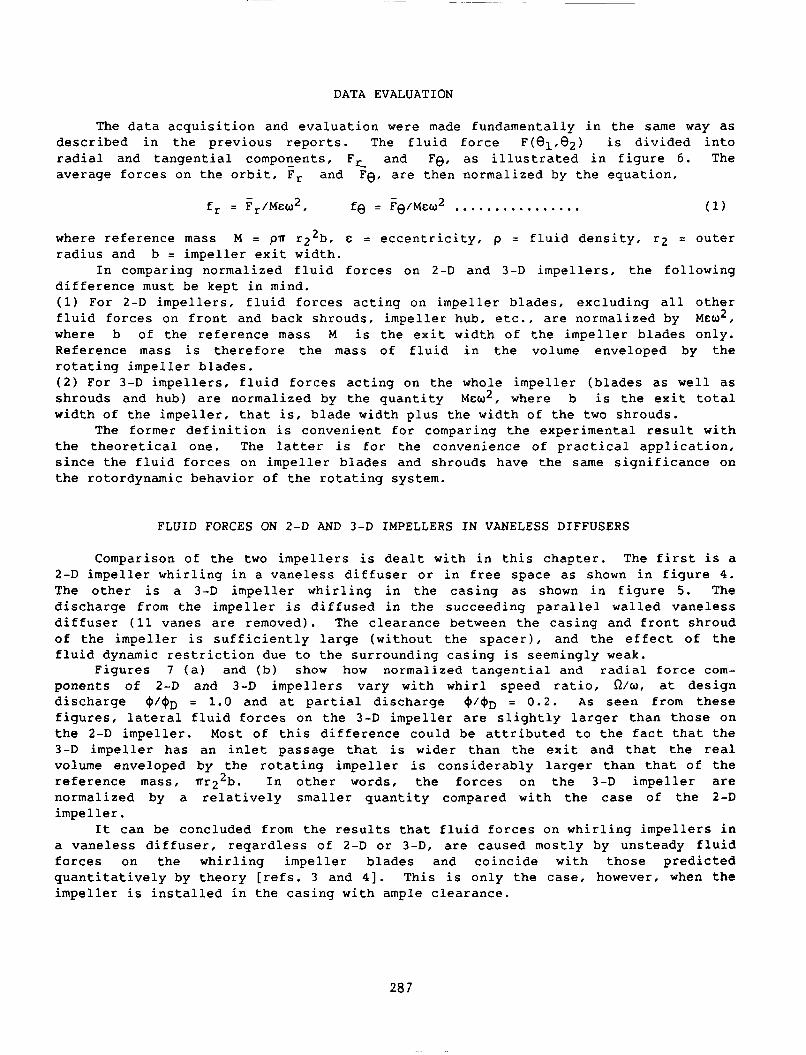
DATA EVALUATION
The data acquisition and evaluation were made fundamentally in the same way as described in the previous reports. The fluid force F(e1 ,e2 ) is divided into radial and tangential compor_:ents, F r_ and Fe, as illustrated in figure 6. The average forces on the orbit, Fr and Fe, are then normalized by the equation,
- 2 fe = Fe/ME:W ............... . (1)
where reference mass M = prr r22b, E: = eccentricity, p = fluid density, r2 = outer radius and b = impeller exit width.
In comparing normalized fluid forces on 2-D and 3-D impellers, the following difference must be kept in mind. (1) For 2-D impellers, fluid forces acting on impeller blades, excluding all other fluid forces on front and back shrouds, impeller hub, etc., are normalized by ME:w2, where b of the reference mass M is the exit width of the impeller blades only. Reference mass is therefore the mass of fluid in the volume enveloped by the rotating impeller blades. (2) For 3-D impellers, fluid forces acting on the whole impeller (blades as well as shrouds and hub) are normalized by the quantity Mew2, where b is the exit total width of the impeller, that is, blade width plus the width of the two shrouds.
The former definition is convenient for comparing the experimental result with the theoretical one. The latter is for the convenience of practical application, since the fluid forces on impeller blades and shrouds have the same significance on the rotordynamic behavior of the rotating system.
FLUID FORCES ON 2-D AND 3-D IMPELLERS IN VANELESS DIFFUSERS
Comparison of the two impellers is dealt with in this chapter. The first is a 2-D impeller whirling in a vaneless diffuser or in free space as shown in figure 4. The other is a 3-D impeller whirling in the casing as shown in figure 5. The discharge from the impeller is diffused in the succeeding parallel walled vaneless diffuser (11 vanes are removed). The clearance between the casing and front shroud of the impeller is sufficiently large (without the spacer), and the effect of the fluid dynamic restriction due to the surrounding casing is seemingly weak.
Figures 7 (a) and (b) show how normalized tangential and radial force components of 2-D and 3-D impellers vary with whirl speed ratio, O!w, at design discharge ~/cj)D = 1. 0 and at partial discharge ~~~D = 0. 2. As seen from these figures, lateral fluid forces on the 3-D impeller are slightly larger than those on the 2-D impeller. Most of this difference could be attributed to the fact that the 3-D impeller has an inlet passage that is wider than the exit and that the real volume enveloped by the rotating impeller is considerably larger than that of the reference mass, rrr 22b. In other words, the forces on the 3-D impeller are normalized by a relatively smaller quantity compared with the case of the 2-D impeller.
It can be concluded from the results that fluid forces on whirling impellers in a vaneless diffuser, reqardless of 2-D or 3-D, are caused mostly by unsteady fluid forces on the whirling impeller blades and coincide with those predicted quantitatively by theory [refs. 3 and 4]. This is only the case, however, when the impeller is installed in the casing with ample clearance.
287

FLUID FORCES ON 3-D IMPELLER IN VANELESS AND VANED DIFFUSERS
In this chapter the influence of the interaction between the impeller blades and guide vanes on the whirling fluid forces is dealt with. A 3-D test impeller was installed in the casing as shown in figure 5. The eleven guide vanes attached between the two parallel walls (see fig. 10) are removable, and whirling tests were conducted for cases with and without guide vanes. The mean radial clearance between the impeller outer periphery and the guide vane inner periphery is 5 mm. When the impeller whirls with eccentricity & = 1.5 mm, the clearance varies between 3.5 and 6.5 mm. Every time a trailing edge of an impeller blade passes in the vicinity of a leading edge of a guide vane, a fluid dynamic interaction takes place, and the blade receives an impulsive force. The impeller/guide vane interaction can be understood as the sum of these individual impulses. The clearance between the casing and front shroud is kept wide (without a spacer) throughout this test series.
Figures 8 (a) and (b) show the comparison at design discharge ~~~D = 1.0 and at partial discharge ~~~D = 0.2. It is obvious that the fluid forces on an impeller in a vaned diffuser are about 50q,o larger than those on an impeller in a vaneless diffuser. It should be noted that the pressure rise in a vaned diffuser is also larger by about 15 to 20qo at the same discharge. The general qualitative tendencies of both cases are essentially the same. As described in the latter chapter, impeller/guide vane interaction generates quite large fluctuating fluid forces on the whirling impeller; however, its influence on fluid forces averaged over an orbit remains relatively small.
As seen in figure 8 (b), both tangential and radial components indicate a local increase at around O!w = 0.1 to 0. 2 at partial discharge. These phenomena are hardly seen near design discharge and are considered as characteristics of partial discharge. The real reason is still unknown. The coupling of the whirling motion with the rotating stall in the diffuser, which is usually 10 to 20<l-o of rotational speed, can be considered as a possible cause.
INFLUENCE OF CLEARANCE BETWEEN CASING AND FRONT SHROUD
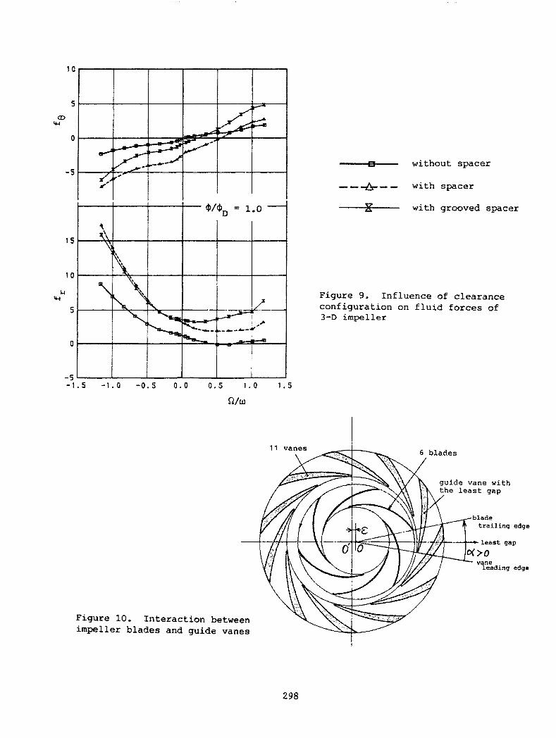
The influence of clearance between the casing and front shroud of the impeller on whirling fluid forces is dealt with in this chapter. Tests were conducted for a 3-D impeller in three cases: (a) without a spacer (original layout); (b) with a spacer, Cl = 2.7 mm, C2 = 3.0 mm (see fig. 5); (c) 24 radial grooves with 10 mm width and 5 mm depth are added to the spacer surface facing the front shroud. Other conditions are the same as those of case (b).
The result obtained at design discharge is summarized in figure 9. As the clearance between the casing and impeller shroud gets smaller and thus the restrictive effect of the fluid contained in the narrow space becomes greater, the fluid forces on the front shroud of the whirling impeller increase. This results in the increase of the radial component and the decrease of the tangential one. Narrower clearance between the impeller and casing leads obviously to the expansion of the whirl excitation range at positive whirl.
The grooves on the spacer surface, which are expected to brake the rotation of fluid in the clearance, resulted in the increase of the tangential component in the positive direction, thus reducing the range of whirl excitation at positive whirl.
288

IMPELLER/GUIDE VANE INTERACTION
The fluid forces on the whirling impeller are a function of both the whirl angle 81 and rotation angle 82. As understood from figure 10, which illustrates the relative disposition of 6 impeller blades and 11 guide vanes, the fluid force at a location of whirl orbit is different according to the relative angular position of the impeller to the guide vanes. Since six impeller blades are equally located on the periphery, the rotational condition becomes identical after every rotation of 60°.
Figure 11 illustrates how fluid force on the whirling impeller varies on the orbit because of the impeller/guide vane interaction. The measurement was done at Olw = 1 and at four discharge conditions: that is, q,;q,D = 1.4, 1.0, 0.6, and 0 (shut off). At 0/w = 1 the trailing edge of a specific impeller blade with the narrowest gap passes successively near the leading edges of the 11 guide vanes during one rotation. This is the reason why 11 distinct interactions can be observed during an orbit. As seen from the figures the interaction becomes obviously weaker as the flow rate decreases. At partial discharge the separation in the impeller and diffuser causes large random fluctuations of flow, and it applies a strong masking effect on the blade interaction.
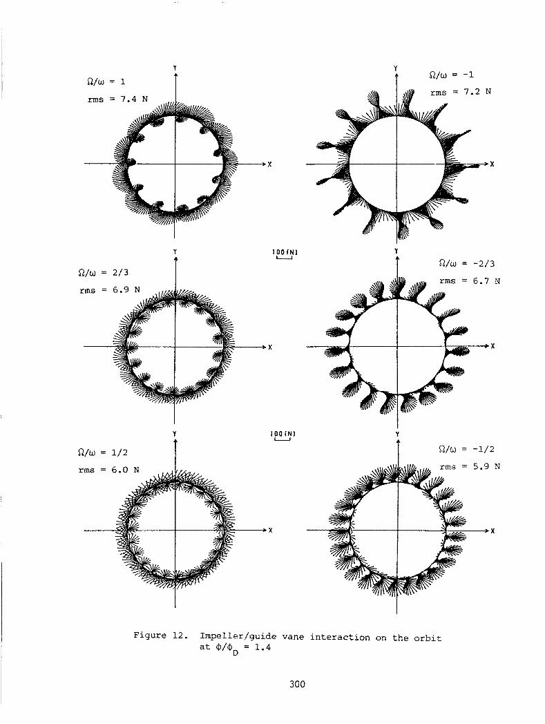
Figure 12 illustrates fluid force vectors on the orbit for various whirl speed ratios, O!w = 2/3, 1/2, -2/3, and -1. The figures are for the over-discharge condition, q,;q,D = 1.4, where the interaction takes place most distinctly. The frequency of periodicity on the orbit varies with the whirl speed ratio and can be explained by tracing the mode of the impeller/guide vane encounter near the minimum gap region.
The impeller/guide vane interaction takes place at every encounter of moving blade and stationary vane, however, the resultant fluid force on the whole impeller is predominantly induced by the blade interaction to a specific guide vane, which is located closest to the least gap point. As illustrated in figure 10, we chose the guide vane with the least gap and the blade closest to the vane. The angle a is then defined as the angle difference between the trailing edge of the blade and the leading edge of the vane. All interaction data at q,;q,D = 1.4 are then replotted against this angle a for three whirl speed ratios, 0/w = 1.0, 1/2, and 1/6, as shown in figure 13, where the tangential and radial components indicate the deviation from the average values on the orbit. This figure suggests that the interactions at various whirl speed ratios are almost identical in nature and are primarily controlled by the local geometric condition near the minimum gap point.
It should be noted again that the interaction, though it appears quite distinctly, is only a local event and has a relatively small effect on the fluid force averaged over the orbit.
Fluid forces on whirling various configurations of the summarized as follows:
CONCLUSIONS
centrifugal impellers are studied experimentally for impeller and diffuser. The results obtained are
(l) Comparison of fluid forces on 2-D and 3-D impellers whirling in a vaneless diffuser indicated no significant difference. ( 2) Fluid forces on a 3-D impeller whirling in a vaned diffuser were about 50'\ larger than those in a vaneless diffuser, partly due to the interaction between the impeller blades and guide vanes and partly to the increased pressure rise. (3) The fluid forces acting on the front shroud of the whirling impeller are affected by the clearance configuration between the casing and shroud. The smaller
289
the clearance, the bigger the fluid forces on the whirling shroud. Grooves cut on the spacer surface facing the shroud do augment the damping effect at positive whirl. (4) Impeller/guide vane interaction generates strong fluctuating fluid forces on the impeller. The effect of this strong interaction on fluid force characteristics is relatively mild as stated above, because high-frequency fluctuations are smoothed out during the averaging process.
lateral fluid force normalized fluid force reference mass whirl angle rotation angle
SYMBOLS
flow coefficient whirl and rotational frequency
subscript D : design (shock-free entry) r, e : radial and tangential
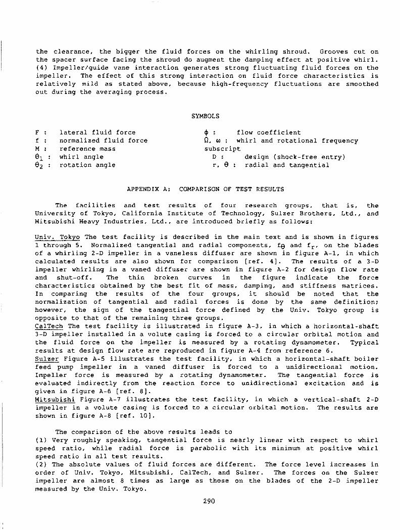
APPENDIX A: COMPARISON OF TEST RESULTS
The facilities and test results of four research groups, that is, the University of Tokyo, California Institute of Technology, Sulzer Brothers, Ltd., and Mitsubishi Heavy Industries, Ltd., are introduced briefly as follows:
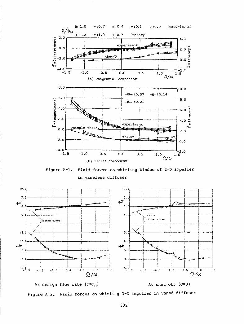
Univ. Tokyo The test facility is described in the main text and is shown in figures 1 through 5. Normalized tangential and radial components, f9 and fr, on the blades of a whirling 2-D impeller in a vaneless diffuser are shown in figure A-1, in which calculated results are also shown for comparison [ref. 4]. The results of a 3-D impeller whirling in a vaned diffuser are shown in figure A-2 for design flow rate and shut-off. The thin broken curves in the figure indicate the force characteristics obtained by the best fit of mass, damping, and stiffness matrices. In comparing the results of the four groups, it should be noted that the normalization of tangential and radial forces is done by the same definition; however, the sign of the tangential force defined by the Univ. Tokyo group is opposite to that of the remaining three groups. CalTech The test facility is illustrated in figure A-3, in which a horizontal-shaft 3-D impeller installed in a volute casing is forced to a circular orbital motion and the fluid force on the impeller is measured by a rotating dynamometer. Typical results at design flow rate are reproduced in figure A-4 from reference 6. Sulzer Figure A-5 illustrates the test facility, in which a horizontal-shaft boiler feed pump impeller in a vaned diffuser is forced to a unidirectional motion. Impeller force is measured by a rotating dynamometer. The tangential force is evaluated indirectly from the reaction force to unidirectional excitation and is given in figure A-6 [ref. 8]. Mitsubishi Figure A-7 illustrates the test facility, in which a vertical-shaft 2-D impeller in a volute casing is forced to a circular orbital motion. The results are shown in figure A-8 [ref. 10].
The comparison of the above results leads to ( 1} Very roughly speaking, tangential force is nearly linear with respect to whirl speed ratio, while radial force is parabolic with its minimum at positive whirl speed ratio in all test results. (2} The absolute values of fluid forces are different. The force level increases in order of Univ. Tokyo, MitsubishL CalTech, and Sulzer. The forces on the Sulzer impeller are almost 8 times as large as those on the blades of the 2-D impeller measured by the Univ. Tokyo.
290
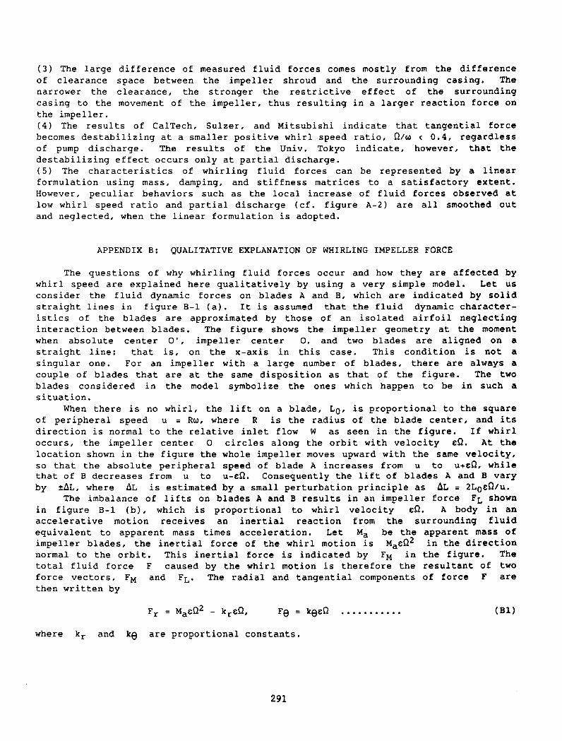
( 3) The large of clearance narrower the casing to the the impeller.
difference of measured fluid forces comes mostly from the difference space between the impeller shroud and the surrounding casing. The clearance, the stronger the restrictive effect of the surrounding movement of the impeller, thus resulting in a larger reaction force on
( 4) The results of Cal Tech, Sulzer, and Mi tsubishi indicate that tangential force becomes destabilizing at a smaller positive whirl speed ratio, Olw < 0.4, regardless of pump discharge. The results of the Univ. Tokyo indicate, however, that the destabilizing effect occurs only at partial discharge. ( 5) The characteristics of whirling fluid forces can be represented by a linear formulation using mass, damping, and stiffness matrices to a satisfactory extent. However, peculiar behaviors such as the local increase of fluid forces observed at low whirl speed ratio and partial discharge (cf. figure A-2) are all smoothed out and neglected, when the linear formulation is adopted.
APPENDIX B: QUALITATIVE EXPLANATION OF WHIRLING IMPELLER FORCE
The questions of why whirling fluid forces occur and how they are affected by whirl speed are explained here qualitatively by using a very simple model. Let us consider the fluid dynamic forces on blades A and B, which are indicated by solid straight lines in figure B-1 (a). It is assumed that the fluid dynamic characteristics of the blades are approximated by those of an isolated airfoil neglecting interaction between blades. The figure shows the impeller geometry at the moment when absolute center 0', impeller center 0, and two blades are aligned on a straight line: that is, on the x-axis in this case. This condition is not a singular one. For an impeller with a large number of blades, there are always a couple of blades that are at the same disposition as that of the figure. The two blades considered in the model symbolize the ones which happen to be in such a situation.
When there is no whirl, the lift on a blade, Lo, is proportional to the square of peripheral speed u = Rw, where R is the radius of the blade center, and its direction is normal to the relative inlet flow W as seen in the figure. If whirl occurs, the impeller center 0 circles along the orbit with velocity t:O. At the location shown in the figure the whole impeller moves upward with the same velocity, so that the absolute peripheral speed of blade A increases from u to U+t:O, while that of B decreases from u to u-t:O. Consequently the lift of blades A and B vary by ~~L, where ~L is estimated by a small perturbation principle as ~L = 2Lot:O/u.
The imbalance of lifts on blades A and B results in an impeller force FL shown in figure B-1 (b), which is proportional to whirl velocity eO. A body in an accelerative motion receives an inertial reaction from the surrounding fluid equivalent to apparent mass times acceleration. Let Ma be the apparent mass of impeller blades, the inertial force of the whirl motion is Mat:02 in the direction normal to the orbit. This inertial force is indicated by FM in the figure. The total fluid force F caused by the whirl motion is therefore the resultant of two force vectors, FM and FL. The radial and tangential components of force F are then written by
(Bl)
where kr and ke are proportional constants.
291
The force characteristics predicted by the above modelling are illustrated in figure B-2 by solid curves. The measured characteristics indicated by thin broken curves are generally similar in shape but do not necessarily cross the origin as solid curves do. Radial and tangential forces at zero whirl speed ratio correspond to direct and cross stiffness, respectively. The above analysis, though it is quite simple and qualitative, suggests the mechanism of whirling fluid force and also its relation to the whirl speed.
As seen from figure B-1 (a), the absolute center 0', which represents the center of suction pipe and thus the location of source Q, changes its relative position to impeller blades during whirl. This induces a source-oriented perturbation on the blades and results in a corresponding unsteady fluid force. This effect has only a secondary significance as compared to the primary effect due to whirl speed-oriented perturbation, however, it constitutes a part of the discrepancy between the model and reality.
REFERENCES
l. Shoji, H. and Ohashi, H., "Fluid Forces on Rotating Centrifugal Impeller with Whirling Motion," NASA CP-2133, 1980, pp. 317 328.
2. Ohashi, H. and Shoji, H., "Lateral Fluid Forces Acting on a Whirling Centrifugal Impeller in Vaneless and Vaned Diffuser," NASA CP-2338, 1984, pp. 109-122.
3. Shoji, H. and Ohashi, H., "Lateral Fluid Forces on Whirling Centrifugal Impeller: Theory," Journal of Fluids Engineering, Vol. 109, 1987, pp. 94-99.
4. Shoji, H. and Ohashi, H., "Lateral Fluid Forces on Whirling Centrifugal Impeller: Experiment in a Vaneless Diffuser," Journal of Fluids Engineering, Vol. 109, 1987, pp. 100-106.
5. Ohashi, H., Hatanaka, R. and Sakurai, A., "Fluid Force Testing Machine for Whirling Centrifugal Impeller," Proc., Intern. Conf. on Rotordynamics, JSME/IFToMM, Sept. 1986, Tokyo, pp. 643-648.
6. Jery, B., Acosta, A.J., Brennen, C.E. and Caughey, T.K., "Hydrodynamic Impeller Stiffness, Damping and Inertia in the Rotordynamics of Centrifugal Flow Pumps," NASA CP-2338, 1984, pp. 137 160.
7. Chamie, D.S., Acosta, A.J., Brennen, C.E. and Caughey, T.K., "Experimental Measurements of Hydrodynamic Radial Forces and Stiffness Matrices for a Centrifugal Pump-Impeller," ASME Journal of Fluids Engineering, Vol. 107, No. 3, 1985, pp. 307-315.
8. Bo11eter, U. and Wyss, A., "Measurement of Hydrodynamic Interaction Matrices of Boiler Feed Pump Impellers," ASME 85-DET-148, 1985.
9. Pace, S.E., Florjancic, S. and Bolleter, U., "Rotordynamic Developments for High Speed Multistage Pumps," Proc., 3rd Intern. Pump symposium, Texas, May 1986, pp. 45-54.
10. Yoshida, Y. and Tsujimoto, Y., "Experimental Study of Fluid Forces on a Centrifugal Impeller Rotating and Whirling in a Volute Casing," JSME, Paper 87-1266A, March 1988 (in Japanese).
292
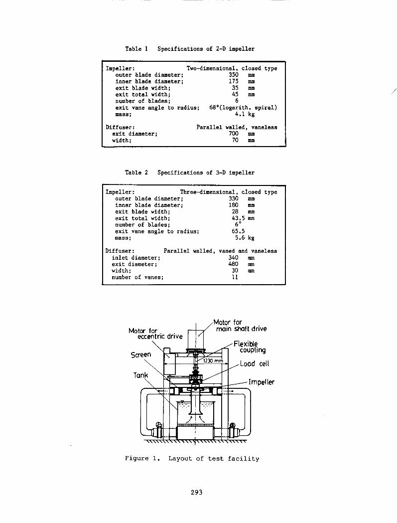
Table 1 Specifications of 2-D impeller
Impeller: Two-dimensional, closed type 350 mm 175 mm 35 mm 45 mm
6
outer blade diameter; inner blade diameter; exit blade width; exit total width; number of blades; exit vane angle to radius; 68°(logarith. spiral)
4.1 kg mass;
Diffuser: exit diameter; width;
Parallel walled, vaneless 700 mm 70 mm
Table 2 Specifications of 3-D impeller
Impeller: Three-dimensional, closed type outer blade diameter; 330 mm inner blade diameter; 180 mm exit blade width; 28 mm exit total width; 43.5 mm number of blades; 6° exit vane angle to radius; 65.5 mass; 5.6 kg
Diffuser: Parallel walled, inlet diameter; exit diameter; width; number of vanes;
vaned and vaneless 340 mm 480 mm
30 mm n
Motor for Motor for
eccentric drive
Screen
main shaft drive
Flexible coupling
Load cell
Figure 1. Layout of test facility
293
/

eccentric drive 110ter shaft
II!Oeller
pul!ll Shaft
eccentric sleeve c inner> eccentric sleeve <outer>
aux. shaft
pulley
Figure 3. Layout of whirling apparatus
294
Figure 2. Cross section of
whirling apparatus

Figure 4. Casing configuration of 2-D impeller
face seal
Figure 5. Casing configuration of 3-D impeller
y
whirl orbit
Figure 6. Coordinate system and force components
295

't-ell>
.. 'f.c
't-ell>
.. 'f.c
10.0
5.0
~ o.o
F-- IT
-s.o (a) 9 I 9p = 1.0
15.0
10.0
5.0 ' -..... ~ -..... ~ ~ -:..... 0.0
-1.0 -o.s 0.0 0.5 1. (! 1.5
10.0 -·-
5.0
o.o ~- --
':P""
-5.0
(b) 9 I 9I> = 0. 2 15.0
10.0
5.0
0.0
~ '~ ~ -......... ~
_ ....... , A --
-5.0
-1.5 -1.0 -o.s 0.0 0. 5 1.0 1.5
Figure h Normalized fluid forces on 2-D and 3-D impellers in vaneless diffuser
296
0
3-D impeller
--b--2-D impeller

I 0. 0
5.0 ,...cr.
- __ ,..;-::;;; ~ 0.0 _...,_ .... -
~ --5.0
(a) tP I tP'D = 1. 0 IS. 0
'0. 0 ... .....
5.0
0.0
~ ~ ~~ ~ ~ ..... "" .....
~
-s.o -1.5 -1.0 -o.s 0.0 0. s 1.0 1.5
10.0
s.o .... Cl>
0.0 ..... ~ ._.., --
.... -~ ~---~
-5.0
(b) l> = 0 2
15.0
10.0 ... .....
5.0
... ~
~ ...... .... """-...... ~ ..... .....
0.0 """"'" _.....
-5.0
-1.5 -1.0 -0.5 0.0 0.5 1.0 1.5
Figure 8. Normalized fluid forces on 3-D impeller in vaneless and vaned diffuser
297
0
vaned diffuser
--A--vaneless diffuser
1 0
5
~ ~
~ -.
~ ~~_..~ ........ ............
~ t-__ ..,.,
~ lo- ..
0
-5
~~~D = 1.0-
" ~\ ~
15
L\. ~ \ / __ ~
'
' ~ -...._ - ~.~ 1----
1"" .... ___ _..,._.,._"'!" " ~ ...;.......,
I
I 0
5
0
-5 -1.5 -1.0 -0.5 0. 0 0.5 1.0
Q/w
1.5
Figure 10. Interaction between impeller blades and guide vanes
298
a without spacer
---l!s--- with spacer
X with grooved spacer
Figure 9. Influence of clearance configuration on fluid forces of 3-D impeller
trailing edge
vane leading edge

50 1Nl 1.---1
y
y
Q>/Q>D = 1. 4
rms = 7.4 N
)(
$/$0
= 0.2
rms = 62 N
y
y
y
Figure 11. Impe11er/guide vane interaction on the orbit at s-2/w = 1
299
1
QJw = 2/3
rms =
ri'2/w =
rms
y
y
y
IOOfNJ L.--1
lOO INI L.--1
y QJw = -1
y
ri'2/w :: -2/3
rms = 6.7 N
0./w = -1/2
5.9 N
Figure 12. Impeller/guide vane interaction on the orbit at <P/4>
0 = 1.4
300

OhHL-----~----~~~----~-----4
-2
-4-
---- n;w = 1/2
-·-n;w = 1/6
r~-:'l_ ·~ '
~ '\ 0~~~----~~+-~~----~~~
-2
0
angle difference a
Figure 13. Force fluctuation plotted against angle a
301
$/ 4>sr l.'!l : 1. 0
+ :1.3 2.0 ...,
c w E ·;::: o.o Cl) 0. >< ~-2.0 (I)
'H -4,0
-1.5
!
I
........-....--• 1
-1.0
&:0.7 X :0.4 (!) :0.1
y :1.0 .,. :0.7 (theory) j
e~eriment ! I
"' I I ; theory
] I -0.5 o.o 0.5
(a) Tangential component
x:O.O
I .£
!
I
(experiment)
~ 4.0
2 .o t' g .r:
0.0 ~ (I)
'H -2.0
1.0 1. 5 0/£1.1
s.or-----;-----,------.----~------~--~ 10.0
..., r:: Cl)
-£1- ±0.07 --:fi-±0.14
""*- ±0.21
·t 4.0 1---~~~--------l'--------·----.~~ w 0.
~ 2.or------~~~~~-----+----+-----:
experiment ~..
'H o.o
(b) Radial component
8.0
6. 0 t' 0 Cl) .r:
4.0 ~
~ 2.0
0.0
Figure A-1. Fluid forces on whirling blades of 2-D impeller
in vaneless diffuser
I 0. Or---r----r----.-----.---.--..........., l I 1 I
I 0. 0
I I
s.or--~l----~----1---~--~--~
~ lt-~:kl:;=;=k=i~~~~~~~~~=~~·=-~-~-~ 0.0
-.c.:..,. ! . -5 • 0 ""'... 1
I
I "Lf.. f I ~- >tted c~rve
15.0 V/: I "·~! i
I
I I
I
0 !
I ! .~ 0
5.
0.
-·~ I 0 I
~. I ~ f 1 t ted ;curve
-5.
OV! I
~ I
I 'L i
15.
I 0. 0
<+= 5.
0.
0
0 I I~ ~-
-5. 0 I I -1. 5 -1. 0 -0.5 0.0
I
I !
1 I
i
i I
0.5
I I ' ! :
I !
i .
.A.
1. 0
S2/w
At design flow rate (Q=Q0 ) At shut-off (Q=O)
Figure A-2. Fluid forces on whirling 3-D impeller in vaned diffuser
302
-
1.5

IUQ
VOLUI! R 110 WIGS
Figure A-3. Test facility of CalTech
Figure A-4. Fluid forces on whirling 3-D impeller in volute casing
303

Figure A-5. Test facility of Sulzer
EF'RIITASK 1 1 llO~'IlALIZEC• RADIAL FORI£ Frt J
50. ' ....... I ~ ~~ ..... V .............
I
'" V j:
F '-~'! ~ . ~-V / 0 v~ )
LOi~ E:':C IT AT 10!1 / EtiERGY RAIIGE J i/ -50.
-1.25 ORBIT FREQ.IROTATinG FREQ. 1.25
EF'RI!TASK 1 IWRilALIZED TAIIGEIITIAL FORCE Ft~ 20.
-20. -I. 25 ORBIT FREQ.IROTATinG FREQ.
Figure A-6. Fluid force on whirling BFP impeller in vaned diffuser
304

flexible coupling
eccentric sleeve
main drive shaft
imp a lie r
suction
(Cuing A)
Theory ... )(.,_ ~h::0.017
Fn• --l::J-- ~ =0.0!51 --o-- ; =0.065
• c: LL.
-2~----~------~----~----~2
~----~~--~----~----~-2 -1.0 -0.!5 0 0.5 1.0
(t)
Q
• tC
drive shaft
timing belt
pu 11 e y
wh l r 1 shaf~
pulley
Figure A-7. Test facility
of Mitsubishi
Figure A-8. Fluid forces on whirling 2-D impeller in volute casing
305

u+e:n
~ ;/ ro
u-oG.~-t' ~·'
\
..,.,....
Figure B-1 (a) Flow model
\ \ \
\
'
F r
direct stiffness (negative) -
keen Fe
/I F
Figure B-1 (b) Force vectors
..,.,... ,< real data
linear '·
cross stiffness (positive)
Figure B-2 Fluid forces on whirling impeller by simple model
306
1\U\51\ Report Documentation Page National Aeronautics and Space Administration
1. Report No. 2. Government Accession No. 3. Recipient's Catalog No.
NASA CP-3026
4. Title and Subtitle 5. Report Date
Rotordynamic Instability Problems in High-Performance February 1989 Turbomachinery-1988
6. Performing Organization Code
553-13-00
7. Author(s) 8. Performing Organization Report No.
E-4227
1 0. Work Unit No.
9. Performing Organization Name and Address 11. Contract or Grant No.
National Aeronautics and Space Administration Lewis Research Center Cleveland, Ohio 44135-3191 13. Type of Report and Period Covered
12. Sponsoring Agency Name and Address Conference Publication
National Aeronautics and Space Administration 14. Sponsoring Agency Code Washington, D.C. 20546-0001
! 15. Supplementary Notes
The workshop was sponsored by Texas A&M University, College Station, Texas; the U.S. Army Research Office, Durham, North Carolina; the Aeropropulsion Laboratory, Wright-Patterson Air Force Base, Ohio; and NASA Lewis Research Center, and held at Texas A&M University on May 16-18, 1988.
! 16. Abstract
I The first rotordynamics workshop proceedings (NASA CP-2133, 1980) emphasized a feeling of uncertainty in predicting the stability of characteristics of high-performance turbomachinery. In the second workshop
I proceedings (NASA CP-2250, 1982) these uncertainties were reduced through programs established to systematically resolve problems, with emphasis on experimental validation of the forces that influence rotordynamics. In the third proceedings (NASA CP-2338, 1984) many programs for predicting or measuring forces and force coefficients in high-performance turbomachinery produced results. Data became available for designing new machines with enhanced stability characteristics or for upgrading existing machines. In the fourth proceedings (NASA CP-2443, 1986) there emerged trend toward a more unified view of rotordynamic instability problems and several encouraging new analytical developments. The present workshop supports the continuing trend toward a unified view with several new developments in the design and manufacture of new turbomachineries with enhanced stability characteristics along with new data and associated numerical/theoretical results. The intent of the workshop and this proceedings is to provide a continuing impetus for an understanding and resolution of these problems.
17. Key Words (Suggested by Author(s)) 18. Distribution Statement
Rotordynamics Unclassified- Unlimited Turbo machinery Subject Category 37 Instability
19. Security Classif. (of this report) 20. Security Classif. (of this page) 21. No of pages 22. Price•
Unclassified Unclassified 459 A20
NASA FORM 1626 OCT 86 *For sale by the National Technical Information Service, Springfield, Virginia 22161