rotodex catalogue v 1.2 - motion technique turret can be made to index round between stopping...
TRANSCRIPT


- 2 - © Copyright 2012. All rights reserved.

- 3 - © Copyright 2012. All rights reserved.

- 4 - © Copyright 2012. All rights reserved.
About Indexing & Indexers
Indexing is the repetitive movement of a
mechanical element, from an initial position
(starting from a rest position also known as dwell)
to a new position. In other words, it can also be
defined as the process of starting and stopping
the motion in precise intervals at precise
locations. Indexing is applied generally to either
linear or rotary applications.
Cam Driven Indexers convert constant rotary
motion at the input shaft into intermittent rotary
motion at the output shaft.
This motion is achieved by the combination of the
Cam, driven generally by a motor and reducer, and a Turret attached to the output shaft which
contains the cam followers. The whole assembly is generally enclosed in an oil filled box known
as Housing.
As the cam rotates, followers on the follower wheel are guided through a path dictated by the
shape of the cam. During specific portion of the input rotation, the cam confines the followers
(and therefore, the output) to a rigid, stationary position called Dwell. During the remainder of
the camshaft rotation, the cam geometry causes the followers to move and the output to
rotate. This movement is called an Index.
The turret can be made to Index round between stopping positions or oscillate between two
stops. The cam can be stopped and restarted when the turret is at rest to extend cycle times. As
the cam is rotated at a constant speed, the output stops and starts (i.e. dwells and indexes) in a
repetitive pattern.
When turrets are required to index first one way then the other, the mechanism is called as an
‘Oscillator’.
GLOBOIDAL CAM INDEXERS & OSCILLATORS
ROTARY TABLE INDEXERS
PARALLEL CAM INDEXERS & OSCILLATORS

- 5 - © Copyright 2012. All rights reserved.
GLOBOIDAL CAM INDEXERS & OSCILLATORS - RS/RF Series
These series of indexers are robust, versatile units suitable for a wide variety of applications and
basically comprise of two elements, the Globoidal cam and radially equispaced cam followers
called Turret. Available as Shaft output (RS) and Flange output (RF), in many sizes to meet a
wide variety of speed, load and space requirements.
• Centre distance : 45 to 250mm
• Number of stops : 2 to 36
• Index angle : 90º to 330º
• Oscillation angle : 1º to 180º
• Accuracy : ±30 Arc seconds
• Optional centre thru-hole in flange version
Ordering code
RS80-6-180R/UW-3B
RS/RF : Shaft type indexer / Flange type indexer
80 : Centre distance
6 : No. of stops
180 : Index angle
R : Cam handing (fig. 1)
UW : Mounting hole face
3 : Shaft projection (fig. 2)
B : Mounting position (fig. 3)
Fig. 1 Cam handing
Fig. 2 Shaft Projection
Fig. 3 Mounting position

- 6 - © Copyright 2012. All rights reserved.
Dimension drawing - RS Series (RS45 to RS83)
Type A B C D E F G H J J1 K K1 L M MA MB MC
RS45 45 45 130 80 160 90 108 45 70 70 10 10 110 16h6 5P9 13 35
RS60 60 55 170 95 190 120 138 60 86 96 12 12 146 20h6 6P9 16.5 35
RS70 70 65 195 115 230 130 148 65 100 100 15 15 165 25h6 8P9 21 40
RS83 83 65.5 222 115 230 160 166 72 110 110 15 25 192 30h6 8P9 26 50
Type N NA NB NC P Q R S T U X Y Z AB AC
RS45 14h6 5P9 11 30 42 40 34 35 45 90 20 65 17 M8 15
RS60 16h6 5P9 13 35 42 40 38 40 55 110 25 75 20 M8 15
RS70 20h6 6P9 16.5 45 52 50 48 50 65 130 35 90 25 M10 15
RS83 20h6 6P9 16.5 36 64 60 40 45 70 140 35 80 25 M12 20

- 7 - © Copyright 2012. All rights reserved.
Dimension drawing - RS Series (RS80 to RS250)
Type A B C D E F G H J K L M MA MB MC N NA NB
RS80 80 80 240 140 280 170 85 130 20 20 200 30h6 8P9 26 50 25h6 8P9 21
RS100 100 95 290 160 320 200 100 140 30 30 230 35h6 10P9 30 75 25h6 8P9 21
RS110 110 100 310 175 350 220 110 190 15 40 230 35h6 10P9 30 80 30h6 8P9 26
RS125 125 110 335 195 390 230 115 170 30 30 275 42h6 12P9 37 80 30h6 8P9 26
RS140 140 130 400 215 430 260 130 200 30 30 340 45h6 14P9 39.5 80 40h6 12P9 35
RS150 150 140 430 245 490 280 140 220 30 30 370 50h6 14P9 44.5 85 40h6 12P9 35
RS180 180 160 500 275 550 350 175 270 40 40 420 60h6 18P9 53 100 50h6 14P9 44.5
RS200 200 190 580 315 630 380 190 290 45 45 490 70h6 20P9 62.5 135 65h6 18P9 58
RS250 250 230 710 365 730 480 240 420 30 65 580 100h6 28P9 90 140 80h6 22P9 71
Type NC P Q R S T U X Y AB AC BD BF BH BJ BK BL AD AE
RS80 50 62 57 57 60 80 160 35 30 M10 20 20 120 20 120 20 200 20 200
RS100 55 85 80 58 60 100 200 40 30 M12 25 30 140 30 140 15 260 15 260
RS110 65 90 85 70 75 100 200 40 35 M12 25 35 130 15 170 20 270 20 270
RS125 70 110 105 78 80 115 230 50 35 M12 25 30 170 30 170 30 275 15 305
RS140 75 90 85 80 85 130 260 50 45 M16 25 30 200 30 200 30 340 30 340
RS150 90 105 100 100 105 140 280 55 45 M16 25 30 220 30 220 30 370 30 370
RS180 100 110 105 110 115 160 320 70 55 M16 30 40 240 25 270 40 420 40 420
RS200 110 145 140 120 125 190 380 85 70 M20 35 45 290 45 290 45 490 45 490
RS250 110 165 150 130 135 230 460 110 85 M20 35 55 350 30 400 40 630 40 630

- 8 - © Copyright 2012. All rights reserved.
Dimension drawing - RF Series
Type A B C D E F G H J K L M N NA NB NC P Q R
RF45 45 45 130 80 160 90 45 70 10 10 110 25h6 14h6 5P9 11 30 30 20 34
RF60 60 55 170 95 190 120 60 96 12 12 146 30h6 16h6 5P9 13 35 20 10 38
RF70 70 65 195 115 230 130 65 100 15 15 165 35h6 20h6 6P9 16.5 45 20 10 48
RF80 80 80 240 140 280 170 85 130 20 20 200 45h6 25h6 8P9 21 45 25 10 50
RF83 83 65.5 222 112 224 160 72.5 110 25 15 192 40h6 20h6 6P9 16.5 36 25 15 40
RF100 100 95 290 160 320 200 100 140 30 30 230 50h6 25h6 8P9 21 55 30 10 58
RF110 110 100 310 175 350 220 110 190 15 40 230 60h6 30h6 8P9 26 65 31 10 70
RF125 125 110 335 195 390 230 115 170 30 30 275 60h6 30h6 8P9 26 70 35 10 78
RF140 140 130 400 215 430 260 130 200 30 30 340 80h6 40h6 12P9 35 75 35 10 80
RF150 150 140 430 245 490 280 140 220 30 30 370 80h6 40h6 12P9 35 90 35 10 100
RF180 180 160 500 275 550 350 175 270 40 40 420 90h6 50h6 14P9 44.5 100 40 10 110
RF200 200 190 580 315 630 380 190 290 45 45 490 110h6 65h6 18P9 58 110 45 10 120
RF250 250 230 710 365 730 480 240 420 30 65 580 130h6 80h6 22P9 71 110 45 15 130
Type S T U X Y Z AB AC BD BF BH BJ BK BL AD AE AF AG AH
RF45 35 45 90 55 85h7 17 M8 15 10 70 10 70 10 110 10 110 M5 10 40
RF60 40 55 110 60 85h7 20 M8 15 12 86 12 86 12 146 12 146 M6 10 45
RF70 50 65 130 75 110h7 25 M10 15 15 100 15 100 15 165 15 165 M8 20 55
RF80 60 80 160 90 125h7 30 M10 20 20 120 20 120 20 200 20 200 M8 18 65
RF83 42 70 140 85 115h7 25 M12 25 15 110 15 110 15 192 15 192 M10 20 65
RF100 60 100 200 110 150h7 30 M12 25 30 140 30 140 30 230 15 260 M10 20 80
RF110 75 100 200 120 160h7 35 M12 25 35 130 15 170 20 270 20 270 M12 25 90
RF125 80 115 230 140 175h7 35 M12 25 30 170 30 170 30 275 15 305 M12 25 110
RF140 85 130 260 150 190h7 45 M16 25 30 200 30 200 30 340 30 340 M12 25 110
RF150 105 140 280 150 190h7 45 M16 25 30 220 30 220 30 370 30 370 M12 25 110
RF180 115 160 320 200 250h7 55 M16 30 40 240 25 270 40 420 40 420 M16 30 150
RF200 125 190 380 220 310h7 70 M20 35 45 290 45 290 45 490 45 490 M16 30 170
RF250 135 230 460 300 380h7 85 M20 35 55 350 30 400 40 630 40 630 M16 30 220

- 9 - © Copyright 2012. All rights reserved.
ROTARY TABLE INDEXERS - RX Series
The RX series adopts the same mechanism as in RS/RF series but the larger turret diameter is
more suited for high number of stops indexing applications. The RX series is ideal for rotary dial
applications with features including large output mounting surface & large centre thru-hole.
• Centre distance : 80 to 250mm
• Number of stops : 2 to 32
• Index angle : 90º to 330º
• Accuracy : ±30 Arc seconds
Ordering code
RX110-12-270L/W-3B
RX : Rotary table indexer
110 : Centre distance
12 : No. of stops
270 : Index angle
L : Cam handing (fig. 4)
W : Mounting hole face
3 : Shaft projection (fig. 5)
B : Mounting position (fig. 6)
Fig. 4 Cam handing
Fig. 5 Shaft Projection
Fig. 6 Mounting position
- 10 - © Copyright 2012. All rights reserved.
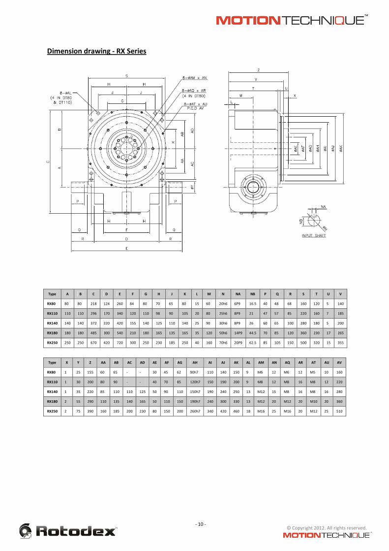
Dimension drawing - RX Series
Type A B C D E F G H J K L M N NA NB P Q R S T U V
RX80 80 80 218 124 260 84 80 70 65 80 15 60 20h6 6P9 16.5 40 48 68 160 120 5 140
RX110 110 110 296 170 340 120 110 98 90 105 20 80 25h6 8P9 21 47 57 85 220 160 7 185
RX140 140 140 372 220 420 155 140 125 110 140 25 90 30h6 8P9 26 60 65 100 280 180 5 200
RX180 180 180 485 300 540 210 180 165 135 165 35 120 50h6 14P9 44.5 70 85 120 360 230 17 265
RX250 250 250 670 420 720 300 250 230 185 250 40 160 70h6 20P9 62.5 85 105 150 500 320 15 355
Type X Y Z AA AB AC AD AE AF AG AH AI AJ AK AL AM AN AQ AR AT AU AV
RX80 1 25 155 60 65 - - 30 45 62 90h7 110 140 150 9 M6 12 M6 12 M5 10 160
RX110 1 30 200 80 90 - - 40 70 85 120h7 150 190 200 9 M8 12 M8 16 M8 12 220
RX140 1 35 220 85 110 110 125 50 90 110 150h7 190 240 250 13 M12 15 M8 16 M8 16 280
RX180 2 55 290 110 135 140 165 50 110 150 190h7 240 300 330 13 M12 20 M12 20 M10 20 360
RX250 2 75 390 160 185 200 230 80 150 200 260h7 340 420 460 18 M16 25 M16 20 M12 25 510

- 11 - © Copyright 2012. All rights reserved.
PARALLEL CAM INDEXERS & OSCILLATORS - RP Series
The RP series is the Parallel Indexer and Oscillator series comprising of conjugate disc cams with
turret having yoke mounted cam followers. This series incorporates parallel input and output
shafts and is most often used for low number of stops and conveyor applications.
• Centre distance : 50 to 200mm
• Number of stops : 1 to 8
• Index angle : 90º to 330º
• Accuracy : ±60 Arc seconds
Ordering code
RP100-3-120/1.8-EF-6
RP : Parallel shaft indexer
100 : Centre distance
3 : No. of stops
120 : Index angle
1.8 : Input shaft projection . Output shaft projection (fig.7)
EF : Mounting hole face
6 : Mounting position (fig. 8)
Fig. 7 Shaft projection
Fig. 8 Mounting position

- 12 - © Copyright 2012. All rights reserved.
Dimension drawing - RP Series
Type A B C D E F G H J K L M MA MB N NA NB
RP50 50 50 155 110 55 45 90 15 125 8 94 16h6 5P9 13 16h6 5P9 13
RP65 65 60 190 130 65 55 110 20 150 10 110 20h6 6P9 16.5 20h6 6P9 16.5
RP80 80 70 230 160 80 60 120 25 180 10 140 25h6 8P9 21 25h6 8P9 21
RP100 100 85 285 200 100 70 140 30 225 15 170 30h6 8P9 26 30h6 8P9 26
RP125 125 105 350 240 120 85 170 35 280 20 200 35h6 10P9 30 30h6 8P9 26
RP160 160 135 450 310 155 100 200 45 360 20 270 45h6 14P9 39.5 45h6 14P9 39.5
RP200 200 165 555 390 195 120 240 55 445 25 340 60h6 18P9 53 50h6 14P9 44.5
RP250 250 200 690 480 240 140 280 75 540 30 420 70h6 20P9 62.5 55h6 16P9 49
Type P Q R S T U V X Y Z AB AC BD BF BH BJ
RP50 35 38 40 10 135 10 70 20 20 7 M6 10 10 70 8 94
RP65 35 42 45 10 170 10 90 25 25 9 M8 15 20 70 10 110
RP80 45 50 55 12 206 12 96 30 30 11 M10 20 25 70 10 140
RP100 52 60 65 15 255 15 110 35 35 11 M10 20 30 80 15 170
RP125 52 60 65 20 310 20 130 40 35 14 M12 20 35 100 20 200
RP160 70 80 85 30 390 20 160 50 50 14 M12 20 35 130 20 270
RP200 90 110 115 35 485 25 190 65 55 18 M16 30 45 150 25 340
RP250 110 130 135 50 590 25 230 75 60 22 M20 35 50 180 30 420

- 13 - © Copyright 2012. All rights reserved.
Dial-Plate Application Data Sheet

- 14 - © Copyright 2012. All rights reserved.
Conveyor Application Data Sheet

- 15 - © Copyright 2012. All rights reserved.
Contact Us:
Motion Technique (India) Pvt. Ltd.
Plot # 375-B, 1st
Floor, Soparkar Ind. Compound,
Road # 15, Behind Josts Engg. Co.,
Wagle Industrial Area, Thane (W), M.S. – 400 604, India
Tel. # +91 22 3291 5388 / +91 22 2580 1243
Fax.# +91 22 25804395
e-mail: [email protected]
Website: www.motiontechnique.com

- 16 - © Copyright 2012. All rights reserved.