rotating mirrors for high energy laser i/i … · o-ri28 728 high-speed scan rotating ... a high...
TRANSCRIPT

O-Ri28 728 HIGH-SPEED SCAN ROTATING MIRRORS FOR HIGH ENERGY LASER i/iSYSTEMS(U) FOREIGN TECHNOLOGY DIV WRIGHT-PATTERSON AFBOH S HU 22 SEP 82 FTD-ID(RS)T-8774-82
UNCLASSIFIED F/G 28/5 N
mE0EE1hhhEl'.
Eli ,,., , 2, 1111 IIIII1.0 M Li I .- g2
III '-M. m II_ ... " -I
* .__12.011.1
lIla &6IH I.I [:" ,,, i7i.
Ls 1.60*o L.0
MICROCOPY RESOLUTION4 TEST CHART
MICROCOPY RESOLUTION TEST CHART . NATIONAL BUREAU Of STANDARDS-1963-ANATIONAL BUREAU OF STANDARDS-1963-A
1 1.0 EM128 LNA.1 J 132136
111.11.4 Q
"III-
MICROCOPY RESOLUTION TEST CHART-. NATIONAL BUREAU OF STANDARDS-1963-A r
1111I 1I1I1 1.1"
//
MICROCOPY RESOLUTION TEST CHART MICROCOPY RESOLUTION lEST CHAAT
NATIONAL BUREAU Of" SrANDARDS-1963-A NAIOAL BfEUOF .1'iOl-|l-

FTD-ID(RS )T-0774-82
FOREIGN TECHNOLOGY DIVISION
A W-6
HIGH-SpEED SCAN ROTATING MIRRORS FOR HIGHENERGY LASER SYSTEMS
by
7, Hu Shaoyi
82. 1022109

FTD -LD(RS)T-0774-82
II
EDITED TRANSLATION
FTD-ID(RS)T-0774-82 22 September 1982
MICROFICHE NR: FTD-82-C-001253
HIGH-SPEED SCAN ROTATING MIRRORS FOR HIGHENERGY LASER SYSTEMS
By: )u Shaoyi
English pages: 13
Source: Jiguang, Vol. 7, Nr. 12, 1980, pp. 27-31; 26
Country of origin: ChinaTranslated by: LEO KANNER ASSOCIATES
F33657-81-D-0264Requester: FTD/TQTDApproved for public release; distribution unlimited.
ie.
THIS TRANSLATION IS A RENDITION OF THE ORIGI.
MAL FOREIGN TEXT WITHOUT ANY ANALYTICAL OR
EDITORIAL COMMENT. STATEMENTS OR THEORIES PREPARED BY:ADVOCATED OR IMPLIED ARE THOSE OF THE SOURCEAND DO NOT NECESSARILY REFLECT THE POSITION TRANSLATION DIVISIONOR OPINION OF THE FOREIGN TECHNOLOGY DI- FOREIGN TECHNOLOGY DIVISIONVISION. WP.APB. OHIO.
FTD -ID(RS)T-0774-82 Date 22 Sep 19 82
p.7

GRAPHICS DISCLAIMER
All figures, graphics, tables, equations, etc. mergedinto this translation were extracted from the bestquality copy available.
.F0
* ,-.;; -
GN W
,Fo
HIGH-SPEED SCAN ROTATING MIRRORS FOR HIGH ENERGY LASER SYSTEMS
Hu Shaoyi
Shanghai Institute of Optics and Fine Mechanics, Chinese Academy of Sciences
Submitted 19 November 1979
Two types of periodic scan rotating mirrors used in highenergy laser systems are introduced. Both rotating mirrorsare driven by air turbines: one of then is supported by ahydrostatic gas bearing while the other is supported by threeholding whels centerlessly. In this paper their design,fabrication and experimental results are described.
When a high brightness laser beam passes through a series of magnifiers in
a high energy Nd glass laser device, there are local temperature differences in
the working medium due to the uneven laser energy field; these temperature dif-
* ferences lead to differences in thermal deformation, diffusion, deterioration of
,.* laser be=n orientation, and lowering of laser brightness.
It is proven to be effective by using the scan light beam method in order
to reduce as inch as possible the effect on light beam orientation by diffusion
phenomenon. The concept of the method is to artificially disturb the light bean
direction in the working medium in order to reduce differences of thermal deforma-tion in the local zones. The key to success and failure of the experiment is the
requirement of a large-diameter, high r.p.m. and high stability scan rotating1
. %--- --- --- o. - -, - .... - -%-.. - ... . ... : -,o- . ,.°-,. -. . o~- -. -, . -,-.**."

mirror, which is to scan, in a certain form, the laser beau entering the magnifier
series; in addition, the wider laser bean as the output from the magnifier series
is again restored by the rotating mirror to a slender light beam as the output.
The schematic diagram of the working principle is shown in Fig. 1. According to
different cross sections of the magnifier, there are also two kinds of shapes
*for the rotating mirror: (1) Ring-shaped scan rotating mirror (for use in rod-
shaped amplifier) and (2) Matrix-shaped scan rotating mirror, an umbrella-shaped
rotating mirror (for use in sheet-shaped magnifier). The structural designs of
these two kinds of rotating mirrors are described in the following:
(2 N
(3)"--.'. (,) *l,*t*5MalifJM lt~
(3) *4
Fig. 1. Schematic diagram oflight channels (N1 and M2 are
reflective mirrors): (a) Ring-shaped scan rotating mirror used
,. for rod-shaped magnifier; (b)Matrix-shaped scan rotating mirrorused for sheet-shaped magnifier.Key: (1) Rod-shaped magnifierseries; C2) Output; (3) Rotatingmirror; (4) From oscillator; (5)Sheet-shaped magnifier series.
qp
2

I. Ring-shaped Scan Rotating Mirror
* Fig. l(a) shows this kind of rotating mirror, which scans the light beam ina ring shape. The working principle of the rotating mirror is similar to theconventional twisting mirror; that is, the normal of the mirror surface formsan angle with the rotating axis. When the mirror blade rotates around its axis,the incident light beam with a certain incident angle displays a conic-shapescanning its light axis after the light beam was reflected from the mirror surface.It differs from the twisting mirror in that the ring-shaped light beam following
magnification should again pass through the back surface B of the same rotating
mirror for restoration. In order to require that the light beam scans at high
speed and restores without distortion to a laser beam as output, a very high degreeof parallelism is required between mirror surfaces A and B. In addition, there
should be a very high stability between these two mirror surfaces during high-
speed rotation. This stability requirement can be met only by making these two
mirror surfaces as both sides of a single mirror plate and the parallelism (lessthan or equal to 5"1 of allowance for deviation from the parallelism) while using
a super-precision optical processing technique. Some degree of difficulty is
brought to the design of the mechanical structure in requiring both sides of a
mirror plate to be useful with a relatively large light aperture of #SO am andvery high rotating speed n.50,O00",40,O0O r.p.m. (corresponding to more than S scansin 10 milliseconds). First, the problem of selecting a bearing should be solved.
Under the conditions of relatively large shaft neck (D60 mm) and very high rotating
speed (D&)2,000,000), the conventional roller bearing and slide bearing (oil-filmbearing) are obviously not satisfactory for this purpose. Only the hydrostatic
* gas bearing is the most Ideal because the bearing has characteristics of low
friction, good stability, and long service life. The author selected the hydro-
static gas bearing for this kind of rotating mirror. Next In order of importance
iselection of power to operate the experimental devicet. To suit this purpose,
tepower device should have a compact structure, short starting time, and high
mrror. Fiue2 shows the structural diagram of the ring-shaped scan rotating
3

NM (a)
(m d)
.m (g)
fi.e (h)
Fig. 2. Structural diagram of 40,000r.p.m. high-speed rotating mirror.Key: (a) Silencer; (b) Shield winding;(c) Bearing; Cd) Rotating shaft; (e)Mirror sleeve; (f) Mirror plate; (g)Pressure winding; (h) Blade wheel; Ci)Outer shell.
1. Design of hydrostatic gas bearing
(1) Determination of bearing parameters: based on the diameter of the light
beam to be scanned, the outer diameter, *66 -, of the mirror frame is adopted as
the neck diameter of the rotating shaft; the overall length of the bearing is
L70 m; and a double-row (six holes evenly distributed in each row) capillary
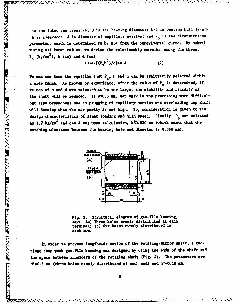
nozzle arrangement is selected for the bearing, as shown in Fig. 3. From the
well-known gas-film bearing calculation formula,
In the equation, R is the air constant; U is the absolute viscosity of air; Cd
is the exhaust coefficient, generally at 0.9; Ts is the absolute temperature; K
is the value of specific heat of the gas; g is the gravitational acceleration; Ps
4
:1T
is the inlet gas pressure; D is the bearing diameter; L/2 is bearing half length;
h is clearance, d is diameter of capillary nozzles; and F is the dimensionless
parameter, which is determined to be 0.4 from the experimental curve. By substi-
tuting all known values, we derive the relationship equation among the three:2
Ps (kg/cm), h (cm) and d (cm)
1034. [(P h)/d]-O.4 (2)
We can see from the equation that Ps, h and d can be arbitrarily selected within
a wide range. As proven by experience, after the value of Ps is determined, if
values of h and d are selected to be too large, the stability and rigidity of
the shaft will be reduced. If d<0.3 m, not only is the processing more difficult
but also breakdowns due to plugging of capillary nozzles and overloading cap shaft
will develop when the air purity is not high. So, consideration is given to the
design characteristics of light loading and high speed. Finally, Ps was selected
as 1.7 kg/ca2 and d=0.4 -m; upon calculation, h0.030 m (which means that the
matching clearance between the bearing hole and diameter is 0.060 mm).
.$
ey (a)Td
(b)
terminal; (b) Six holes evenly distributed ineach row.
the space between shoulders of the rotating shaft (Fig. 3). The parameters are
d'-0.S me (three holes evenly distributed at each end) and h=0.10 sm.
S
*-7

(2) Selection of materials: A two-layer structure is used for the bearing.
The outer-sleeve is made of aluminum bronze ZQA19-4, which is high in strength and
has desirable anti-corrosion characteristics. The material for the inner sleeve
is the electrochemical graphite DM4, which has the characteristics of good anti-
sticking viscosity and grinding resistance. The material is, by itself, a good
solid lubricant, since it can prevent those undesirable phenomena of sticking
to the shaft and rough scratching on the surface of the shaft neck due to occasional
*,} collision abrasion during starting or high-speed rotation of the mirror.
The material for the rotating shaft is stainless steel 4Crl3; the surface
hardness should be HR£kS5 after heat treatment. The outer circle of the shaft
should be precisely ground to over VlO; the clearance between the shaft hole
diameter and the shaft is 0.060+0. 005-
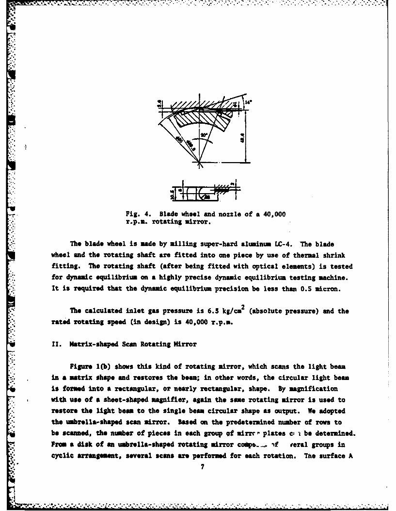
2. Design of blade wheel of air turbine
A remodeled impact type turbine blade wheel is selected because of the simplic-
ity in the manufacturing technique of the blade wheel and under conditions allowing
*- proper reduction of efficiency to some extent. The main characteristic of the
blade wheel is that the position of the nozzle is perpendicular to the main rotating
shaft, as shown in Fig. 4. The parameters of the blade wheel can be designed
and determined by the use of the classical calculation forula for impact type blade
wheels (the calculation is omitted here). Finally, the parameters of the blade
wheel are determined as follows:
Assuming that the diameter of the nozzle ring (D=90 a) and blade-wheel
diameter Do=89.9 s; blade number Z=18 and O-20 e , then the maximum height of the
blade: ho (Do/2) (1-cos e)%2.6 a.
The distance (between the nozzle and the shaft line of rotation) H-(D 0/2)-(h/2)=.43.6 m. The tangent angle (between the nozzle central-line and the wheel circus-
ference) C I n (2/D )%14".
We assume that the blade width =10.S m, are radius R=6 mm, B n2 mm, nozzle
diameter dal ma, and nozzle number n=6.
*,. 6
2
. . -. ...
•. - . . J
Fig. 4. Blade wheel and nozzle of a 40,000r.p.m. rotating mirror.
The blade wheel is made by milling super-hard aluminum LC-4. The blade
wheel and the rotating shaft are fitted into one piece by use of thermal shrink
fitting. The rotating shaft (after being fitted with optical elements) is tested
for dynamic equilibrium on a highly precise dynamic equilibrium testing machine.
It is required that the dynamic equilibrium precision be less than 0.5 micron.
The calculated inlet gas pressure is 6.3 kg/cm2 (absolute pressure) and the
rated rotating speed (in design) is 40,000 r.p.m.
II. Matrix-shaped Scan Rotating Mirror
Figure I(b) shows this kind of rotating mirror, which scans the light beam
in a matrix shape and restores the beam; in other words, the circular light beam
is formed into a rectangular, or nearly rectangular, shape. By magnification
Swith use of a sheet-shaped magnifier, again the same rotating mirror is used to
restore the light beam to the single beam circular shape as output. We adopted
the umbrella-shaped scan mirror. Based on the predetermined number of rows to
be scanned, the number of pieces in each group of mirrr" plates ci a be determined.
From a disk of an umbrella-shaped rotating mirror cop.._. -f veral groups in
cyclic arrangement, several scans are performed for each rotation. Tne surface A
7

of the mirror is the scan mirror surface, and the surface B is the restored mirror
surface. The working principle of the scan (see Fig. 5) and main parameters of
the mirror plate are determined as follows:
0 -- the included angle between the normal of the reflecting surface of the
mirror plate, and the shaft line of the scan mirror rotation;
a-- the scan angle (scan field angle) a(h/l* ). h is the height of themaxlast working medium; P. is the distance from the last piece of working mediummaxto the scan mirror. V 1 +( and
Y __ the field angle (y=CB/R)) between the scan mirror center to the mirror-
plate thickness. B is the width of the mirror plate and R is the radius of the
* scan mirror.
0
Fig. 5. uiagram showing the scan principleof the umbrella-shaped rotating mirror.Key: *)Rotating shaft of scan mirror.
The value of 0 can be determined by the relationship of the three. When thescan mirror is turned by an angle y Cin radians), it is required that the lightbeam scan an angle a(in radians); that is, the mirror surface deflects (1/2)m
* radians. The relationship of the three is:
din M2
In he quaion 00is the value of 0 of the reflective mirror corresponding to
the central line. If the scan is conducted on several rows, it is required
that two adjacent light beams can be separated when the scan light beam reaches
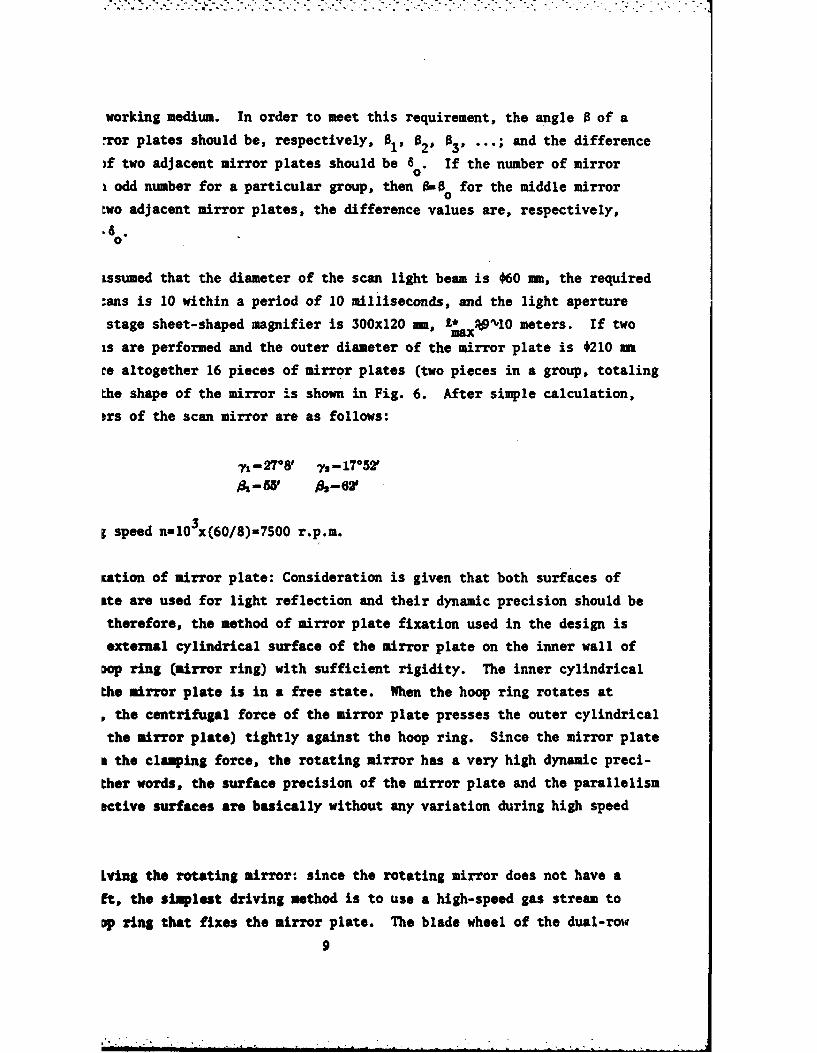
working medium. In order to meet this requirement, the angle B of a
rror plates should be, respectively, 01, 82, 83, ... ; and the difference
)f two adjacent mirror plates should be 8 . If the number of mirroro
i odd number for a particular group, then 0BB for the middle mirror
:wo adjacent mirror plates, the difference values are, respectively,• .
.60
ssumed that the diameter of the scan light beam is 060 mm, the required
:ans is 10 within a period of 10 milliseconds, and the light aperture
stage sheet-shaped magnifier is 300x120 m, LZa* 9 'l0 meters. If two
is are performed and the outer diameter of the mirror plate is 0210 m
re altogether 16 pieces of mirror plates (two pieces in a group, totaling
the shape of the mirror is shown in Fig. 6. After simple calculation,
trs of the scan mirror are as follows:
7- 27 08 ys- 17 *52 '6-55, 0-621
g speed nlO 3x(60/8)=7500 r.p.m.
Kation of mirror plate: Consideration is given that both surfaces of
ite are used for light reflection and their dynamic precision should be
therefore, the method of mirror plate fixation used in the design is
external cylindrical surface of the mirror plate on the inner wall of
Dop ring (mirror ring) with sufficient rigidity. The inner cylindrical
the mirror plate is in a free state. When the hoop ring rotates at
the centrifugal force of the mirror plate presses the outer cylindrical
the mirror plate) tightly against the hoop ring. Since the mirror plate
a the clasping force, the rotating mirror has a very high dynamic preci-
ther words, the surface precision of the mirror plate and the parallelism
ective surfaces are basically without any variation during high speed
Lying the rotating mirror: since the rotating mirror does not have a
Et, the simplest driving method is to use a high-speed gas stream to
Dp ring that fixes the mirror plate. The blade wheel of the dual-row
9
pneumatic turbine made of hard aluminum is connected to the hoop ring in a
single piece by use of thermal shrink fitting. The blade wheel is driven by
compressed air from the nozzle. The design method of the dual-row blade wheel
and nozzle is basically the same as the design of the pneumatic rotating mirror
mentioned above.
* C '
• i
175' 1'z
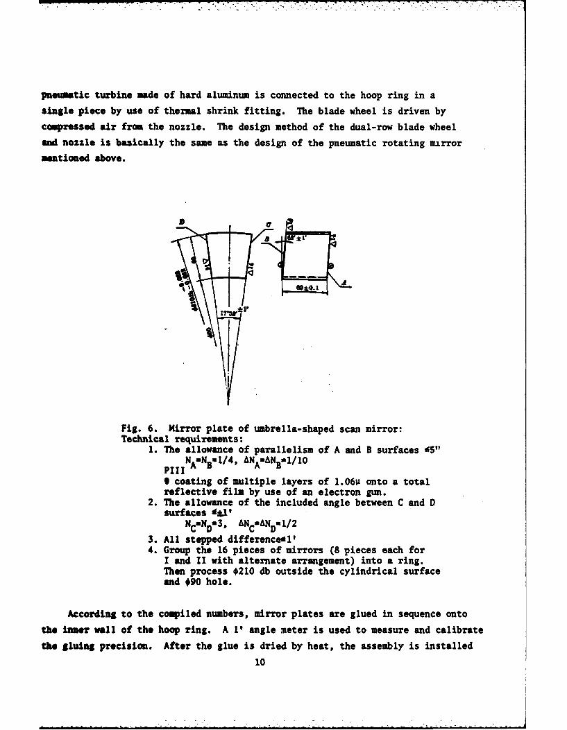
Fig. 6. irror plate of umbrella-shaped scan mirror:Technical requirements:
1. The allowance of parallelism of A and B surfaces £5"Pii NAuNB1/ 4, ANA"ANB"0/10
9 coating of multiple layers of 1.060 onto a totalreflective film by use of an electron gun.
2. The allowance of the included angle between C and Dsurfaces '*1'
Nc=ND=$. ANcuANDU1/2
3. All stepped differenceil'4. Group the 16 pieces of mirrors (8 pieces each for
I and II with alternate arrangement) into a ring.Then process *210 db outside the cylindrical surfaceand *90 hole.
According to the compiled numbers, mirror plates are glued in sequence onto
the iroer wall of the hoop ring. A 1? angle meter is used to measure and calibrate
the gluing precision. After the glue is dried by heat, the assembly is installed
10
on a special clamping fixture and dynamic equilibrium of the entire rotating
mirror ring (including blade wheel) is calibrated; the required precision for
dynamic equilibrium is less than I micron.
(C) Support of the rotating mirror: A support wheel props the outer cylindri-
cal surfa ce of the high-speed rotating mirror ring to solve difficulties due to
the core-less shaft. The ratio between the diameter of the outer surface of the
hoop ring and the diameter of the support wheel is 2:1. Four C100 ball bearings
are used as props to the support wheel; the shaft of the ball bearing uses atomized
oil as a lubricant. The processing precisions of support wheel, hoop ring and
support seat can ensure the dynamic precision and stability of the high-speed
* rotating mirror. Two conical surfaces of the pressure wheel are used to restrain
* the axial-direction motion of the rotating mirror.
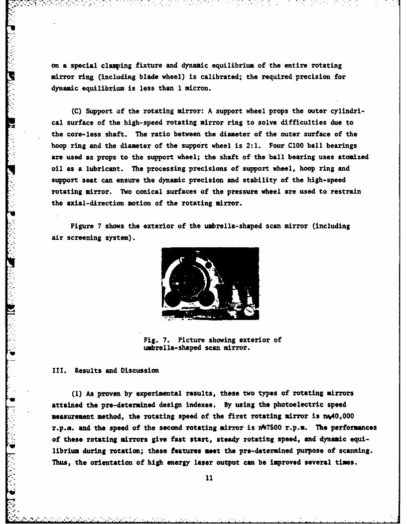
Figure 7 shows the exterior of the umbrella-shaped scan mirror (including
air screening system).
Fig. 7. Picture showing exterior of* umbrella-shaped scan mirror.
Ill. Results and Discussion
(1) As proven by experimental results, these two types of rotating mirrors
attained the pre-determined design indexes. By using the photoelectric speed
* measurement method, the rotating speed of the first rotating mirror is n%40,000
r.p.m. and the speed of the second rotating mirror is A%7SOO r.p.m. The performances
of these rotating mirrors give fast start, steady rotating speed, and dynamic equi-
V librium during rotation; these features meet the pre-determined purpose of scanning.
Thus, the orientation of high energy laser output can be improved several times.
(2) The method of fixation of the mirror plate onto the umbrella-shaped
rotating mirror is rational. During high-speed rotation, the mirror plates are
only acted on by centrifugal force without appreciable deformation. The shearingand equal-thickness interference methods in experiments make dynamic and static
measurements for the same mirror plate for comparison; the results prove that
the wedge-shaped and surface type deformations are within the desirable allowance
range. The effect of the scan and restoration of rotating mirror is satisfactory.
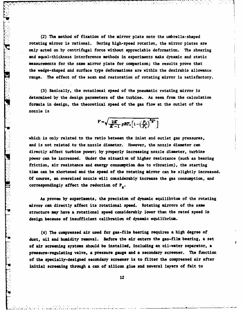
(3) Basically, the rotational speed of the pneumatic rotating mirror is
determined by the design parameters of the turbine. As seen from the calculation
formula in design, the theoretical speed of the gas flow at the outlet of the
nozzle is
which is only related to the ratio between the inlet and outlet gas pressures,
and is not related to the nozzle diameter. However, the nozzle diameter can
directly affect turbine power; by properly increasing nozzle diameter, turbine
power can be increased. Under the situati-)n of higher resistance (such as bearing
friction, air resistance and energy consumption due to vibration), the starting
time can be shortened and the speed of the rotating mirror can be slightly increased.
Of course, an oversized nozzle will considerably increase the gas consumption, and
correspondingly affect the reduction of P .
As proven by experiments, the precision of dynamic equilibrium of the rotating
mirror can directly affect its rotational speed. Rotating mirrors of the sameU structure may have a rotational speed considerably lower than the rated speed in
* design because of insufficient calibration of dynamic equilibrium.
(4) The compressed air used for gas-film bearing requires a high degree ofU dust, oil and humidity removal. Before the air enters the gas-film bearing, a set
of air screening systems should be installed, including an oil-water separator, apressure-regulating valve, a pressure gauge and a secondary screener. The function
of the specially-designed secondary screener is to filter the compressed air after
U initial screening through a can of silicon glue and several layers of felt to
12
further remove tiny dust particles and water vapor in the air. The silicon glue
and felt should be periodically dried and discarded.
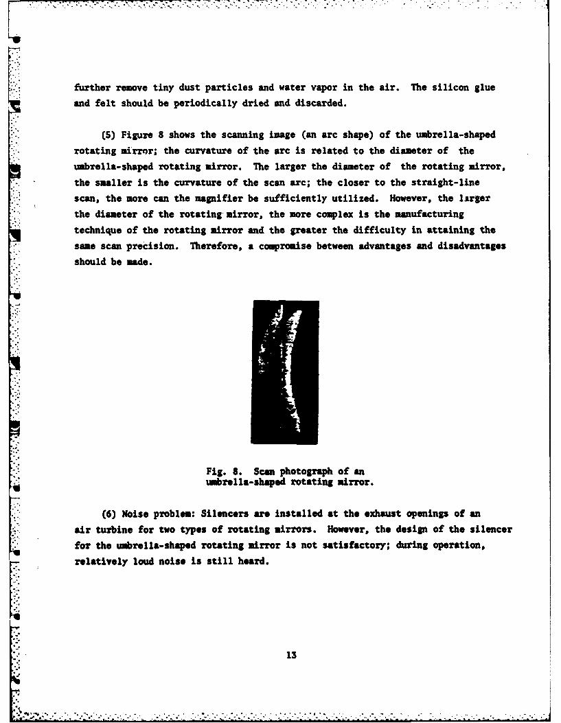
(5) Figure 8 shows the scanning image (an arc shape) of the umbrella-shaped
rotating mirror; the curvature of the arc is related to the diameter of the
umbrella-shaped rotating mirror. The larger the diameter of the rotating mirror,
the smaller is the curvature of the scan arc; the closer to the straight-line
scan, the more can the magnifier be sufficiently utilized. However, the larger
the diameter of the rotating-mirror, the more complex is the manufacturing
technique of the rotating mirror and the greater the difficulty in attaining thesame scan precision. Therefore, a compromise between advantages and disadvantages
should be made.
Fig. 8. Scan photograph of anumbrella-shaped rotating mirror.
(6) Noise problem: Silencers are installed at the exhaust openings of an
air turbine for two types of rotating mirrors. However, the design of the silencer
for the umrella-shaped rotating mirror is not satisfactory; during operation,
relatively loud noise is still heard.
13