rotary microfilter media evaluation - savannah river site
TRANSCRIPT

This document was prepared in conjunction with work accomplished under Contract No. DE-AC09-96SR18500 with the U. S. Department of Energy.
DISCLAIMER This report was prepared as an account of work sponsored by an agency of the United States Government. Neither the United States Government nor any agency thereof, nor any of their employees, nor any of their contractors, subcontractors or their employees, makes any warranty, express or implied, or assumes any legal liability or responsibility for the accuracy, completeness, or any third party's use or the results of such use of any information, apparatus, product, or process disclosed, or represents that its use would not infringe privately owned rights. Reference herein to any specific commercial product, process, or service by trade name, trademark, manufacturer, or otherwise, does not necessarily constitute or imply its endorsement, recommendation, or favoring by the United States Government or any agency thereof or its contractors or subcontractors. The views and opinions of authors expressed herein do not necessarily state or reflect those of the United States Government or any agency thereof.

WSRC-TR-2005-00205 Rev. 0
Rotary Microfilter Media Evaluation
Michael R. Poirier, David T. Herman, and Samuel D. Fink
April 20, 2005

2 WSRC-TR-2005-00205 Rev. 0
ABSTRACT Savannah River National Laboratory (SRNL) received funding from DOE EM-21, Office of Cleanup Technologies, to develop the rotary microfilter for high level radioactive service. One aspect of this project evaluated alternative filter media to select one for the 2nd generation rotary microfilter being procured as a prefilter to a small column ion exchange process. The authors conducted screening tests on a variety of filter media and pore sizes using a stirred cell followed by pilot-scale testing on a more limited number of filter media and pore sizes with a three disk rotary microfilter. These tests used 5.6 molar sodium supernate, and sludge plus monosodium titanate (MST) solids. The conclusions from this work follow.
• The 0.1 µ nominal TruMem® ceramic and the Pall PMM M050 (0.5 µ nominal) stainless steel filter media produced the highest flux in rotary filter testing.
• The Pall PMM M050 media produced the highest flux of the stainless steel media tested in rotary filter testing.
• The Pall PMM M050 media met filtrate quality requirements for the rotary filter. • The 0.1 µ TruMem® and 0.1 µ Pall PMM media met filtrate quality requirements as well. • The Pall PMM M050 media produced comparable flux to the 0.1 µ TruMem® media, and
proved more durable and easier to weld. Based on these test results, the authors recommend Pall PMM M050 filter media for the 2nd generation rotary microfilter. INTRODUCTION The Savannah River Site (SRS) is developing processes to treat radioactive waste. The first step of many of these processes is MST addition to sorb strontium and select actinides followed by filtration to remove the MST and entrained sludge solids. The filtrate may receive additional treatment to remove cesium. Crossflow microfiltration is the baseline process for removing the sludge and MST in these processes. SRNL researchers identified and tested the rotary microfilter as an alternative to the crossflow filters.1,2,3,4 The testing showed significant improvement in filter flux with the rotary microfilter over the baseline crossflow filter (i.e., 2.5 – 6.5 X during the scoping tests, up to 10 X in the actual waste tests, and approximately 2 X in the pilot-scale tests). SRNL received funding from DOE EM-21, Office of Cleanup Technologies, to develop the rotary microfilter for high level radioactive service. The work focused on evaluating alternative rotary microfilter vendors; redesigning the equipment for radioactive service; engineering studies to evaluate the risks; determining downstream impacts, costs and benefits of deploying this technology; performing actual waste and pilot-scale testing of the technology; and evaluating alternative filter media.
3 WSRC-TR-2005-00205 Rev. 0
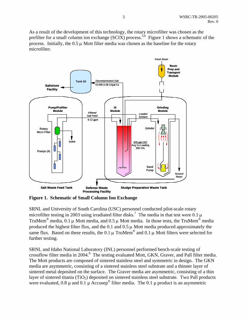
As a result of the development of this technology, the rotary microfilter was chosen as the prefilter for a small column ion exchange (SCIX) process.5,6 Figure 1 shows a schematic of the process. Initially, the 0.5 µ Mott filter media was chosen as the baseline for the rotary microfilter.
Salt Waste Feed Tank Sludge Preparation Waste Tank
Ground Resin
Grinding Module
Sand Pump
IX Module
Loaded Sorbent
Filtered Salt Feed
Solids
Rotary Micro Filter
Pumps (4)
Pump/PrefilterModule
Grinder
Resin Prep and Transport
Module
Fresh Resin
Decontaminated SaltTank 50
Defense Waste Processing Facility
SaltstoneFacility
<0.005-0.08 Ci/gal Cs
6-12 gpm
375 gal CSTAvg Cs Loading
300 Ci/L
Figure 1. Schematic of Small Column Ion Exchange SRNL and University of South Carolina (USC) personnel conducted pilot-scale rotary microfilter testing in 2003 using irradiated filter disks.7 The media in that test were 0.1 µ TruMem® media, 0.1 µ Mott media, and 0.5 µ Mott media. In those tests, the TruMem® media produced the highest filter flux, and the 0.1 and 0.5 µ Mott media produced approximately the same flux. Based on these results, the 0.1 µ TruMem® and 0.1 µ Mott filters were selected for further testing. SRNL and Idaho National Laboratory (INL) personnel performed bench-scale testing of crossflow filter media in 2004.8 The testing evaluated Mott, GKN, Graver, and Pall filter media. The Mott products are composed of sintered stainless steel and symmetric in design. The GKN media are asymmetric, consisting of a sintered stainless steel substrate and a thinner layer of sintered metal deposited on the surface. The Graver media are asymmetric, consisting of a thin layer of sintered titania (TiO2) deposited on sintered stainless steel substrate. Two Pall products were evaluated, 0.8 µ and 0.1 µ Accusep® filter media. The 0.1 µ product is an asymmetric

4 WSRC-TR-2005-00205 Rev. 0
membrane comprised of a sintered zirconia (ZrO2) layer on a sintered stainless steel support. The 0.8 µ product is symmetric and comprised of sintered stainless steel. The testing showed the Pall Accusep® and Graver media produced higher flux than Mott and GKN media with simulated SRS waste. Graver filter media are not available in flat sheets, which are required for fabrication of the filter disks in the rotary filter. The Accusep® media is not available in flat sheets, but Pall PMM media is made by similar process and is available in flat sheets. The authors decided to evaluate Pall PMM media with the rotary microfilter.
SRNL and USC personnel conducted pilot-scale testing with welded disks in 2004.9 This testing evaluated three manufacturers of media: TruMem®, Mott, and Pall (PMM media). The TruMem® filter disks have a 185 µ thick stainless steel substrate and a thin (15 µ) nanopowder coating of ceramic (TiO2) bonded to the substrate. The ceramic coating has a smooth surface that resists fouling which occurs with conventional "depth" type ceramic membranes. The TruMem® media is the baseline for SpinTek rotary filters. The Mott filters are fabricated by sintering stainless steel powder to produce porous membranes. The Mott media are 0.028” thick. The Pall PMM media is a thin, sintered matrix of stainless steel powder within the pore structure of stainless steel wire mesh. The PMM media are 0.006” thick. Since the Pall media produced higher flux than Mott media, the Mott media was removed from consideration with the rotary microfilter. This study evaluated different filter media in the rotary microfilter to select the optimum filter media for the two 25-disk units currently being procured. This testing evaluated and tested TruMem® ceramic media, Pall PMM stainless steel media, and Pall PSS stainless steel media. The Pall PSS media are fabricated by sintering a stainless steel powder. The media are 0.045” thick. We evaluated these media to determine whether a different fabrication process would produce media better suited for our application. The criteria for the rotary filter disks follow:
• Filter flux 0.1 – 0.3 gpm/ft2 • Filtrate turbidity < 5 – 10 NTU • Good filter reliability/durability
TESTING Stirred-Cell Dead-End Filter Testing We used a stirred-cell dead-end filter as a screening tool to evaluate a large number of filter media and pore sizes in a shorter time and at lower cost than performing pilot-scale testing with each.10 Previous SRNL testing showed dead-end filters, like the stirred cell, produce good qualitative indication of how material filters in a crossflow filter.11 Personnel conducted the stirred cell (see Figure 2) tests as follows. They prepared samples of feed solution and stirred them with a magnetic stirrer. Some feed solutions contained only supernate, while others contained supernate, sludge, and MST. They then poured the solution (~35 mL) into the stirred cell. They agitated the cell contents, pressurized the cell (10 - 30 psi), and measured the filtrate volume as a function of time. They analyzed filtrate samples for turbidity with a Orbeco-Hellige turbidity meter.

5 WSRC-TR-2005-00205 Rev. 0
In tests with sludge and MST, personnel filtered multiple batches of feed with the same filter disk to measure changes in filtration rate and filtrate turbidity filtrate volume.
Stirrer
Graduations
Filtermedia
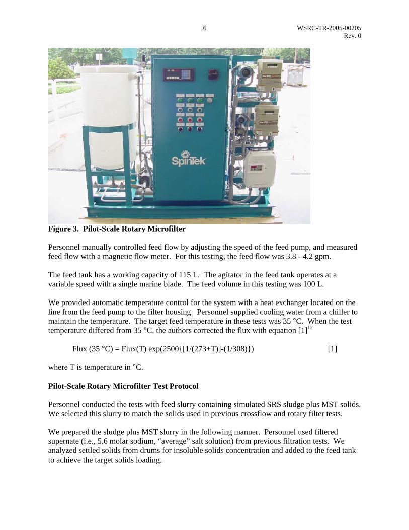
Figure 2. Stirred-Cell Dead-End Filter Unit Pilot-Scale Rotary Microfilter Equipment The pilot-scale rotary microfilter unit (SpinTek) is a Model ST-II-3, Laboratory Test Unit with up to three membrane disks for a maximum of 3 ft2 active membrane area (see Figure 3). The disks spin inside a pressurized vessel with spoked turbulence promoters above and below each disk. Personnel can manually adjust the speed of the disk rotation between 500 and 1400 rpm. Increasing the rotational speed increases the shear forces at the surface of the disk. For this test, the disk rotational speed was 1170 ± 20 rpm. A valve on the concentrate exit automatically controls the pressure inside the filter housing to an operator entered set point. This pressure provides the transmembrane pressure required to force filtrate through the filter membranes. For the purpose of this test, the pressure was 40 psi. The feed slurry flows across the surface of the filter disks. A differential pressure drives the supernate through the filter membrane and into the center of the disks. The filtrate moves to the center of the disk and flows through the hollow shaft holding the disks. Personnel measured filtrate flow with a magnetic flow meter.
6 WSRC-TR-2005-00205 Rev. 0
Figure 3. Pilot-Scale Rotary Microfilter Personnel manually controlled feed flow by adjusting the speed of the feed pump, and measured feed flow with a magnetic flow meter. For this testing, the feed flow was 3.8 - 4.2 gpm. The feed tank has a working capacity of 115 L. The agitator in the feed tank operates at a variable speed with a single marine blade. The feed volume in this testing was 100 L. We provided automatic temperature control for the system with a heat exchanger located on the line from the feed pump to the filter housing. Personnel supplied cooling water from a chiller to maintain the temperature. The target feed temperature in these tests was 35 °C. When the test temperature differed from 35 °C, the authors corrected the flux with equation [1]12 Flux (35 °C) = Flux(T) exp(2500{[1/(273+T)]-(1/308)}) [1] where T is temperature in °C. Pilot-Scale Rotary Microfilter Test Protocol Personnel conducted the tests with feed slurry containing simulated SRS sludge plus MST solids. We selected this slurry to match the solids used in previous crossflow and rotary filter tests. We prepared the sludge plus MST slurry in the following manner. Personnel used filtered supernate (i.e., 5.6 molar sodium, “average” salt solution) from previous filtration tests. We analyzed settled solids from drums for insoluble solids concentration and added to the feed tank to achieve the target solids loading.

7 WSRC-TR-2005-00205 Rev. 0
Once the feed tank contained the desired slurry, personnel started the rotary microfilter and circulated the feed for the selected time, measuring the feed slurry temperature, the feed flow rate, the feed pressure, the filtrate flow rate, and the rotor speed. They periodically collected filtrate samples and analyzed them for solid particles by measuring turbidity. Table 1 shows the feed slurries and filter media tested. Table 1. Feed Slurries for Pilot-Scale Rotary Microfilter Tests Filtera Feed Solids (wt %) Run Time (h) 0.1 µ TruMem® 0.05 5 0.1 µ TruMem® 0.1 15 0.1 µ TruMem® 0.29 5 0.1 µ TruMem® 1.29 23 0.1 µ Pall PMM 0.29 9 0.5 µ Pall PMM 0.1 5 0.5 µ Pall PMM 0.29 8 0.5 µ Pall PMM 1.29 8 0.5 µ Pall PMM 4.5 8 0.5 µ Pall PMM 7.5 8 0.5 µ Pall PMM 12.5 8 1.0 µ Pall PMM 0.06 4 1.0 µ Pall PMM 0.29 4 1.0 µ Pall PMM 1.29 4 1.0 µ Pall PMM 4.5 4 a pore sizes are nominal RESULTS Stirred-Cell Dead-End Filter Tests SRNL personnel performed screening tests using a stirred cell10 to evaluate a variety of filter media and pore sizes and select one for additional pilot-scale rotary filter tests. The following media were selected for stirred cell testing: Pall PMM, Pall PSS, TruMem®, and Mott. Researchers obtained samples of these media types in various pore sizes ranging from 0.1 µ to 2.0 µ nominal for testing. They conducted some limited testing with TruMem® and Mott media for comparison. Figure 4 shows the stirred cell filtration rates with the different media using 5.6 molar sodium supernate. Since the feed did not contain solid particles, the filtration rate is only a function of transmembrane pressure and filter media resistance. Each media is represented by a different color/pattern, and the multiple bars for a given media are from replicate runs. The Pall PMM media produced higher flux than the Pall PSS media. One likely cause of the result is the PMM media being thinner (0.006’ versus 0.045”). The increased thickness increases the resistance of the filter media. The different manufacturing process could contribute

8 WSRC-TR-2005-00205 Rev. 0
as well. Filter flux increased with increasing pore size which agrees with filtration theory.13 Not much difference is observed between the 1.5 µ Pall PMM, the 2.0 µ Pall PMM, and the control containing no filter media. In these tests the resistance of the stirred cell and tubing is much greater than the resistance of the filter media, and controls the filtration rate. Because of these results and the PMM media being easier to work with and weld, future testing focused on that media.
0
2
4
6
8
10
Non
e0.
1 Pa
ll0.
1 Pa
ll0.
1 Pa
ll0.
1 Pa
ll0.
5 Pa
ll0.
5 Pa
ll0.
5 Pa
ll0.
5 Pa
ll1.
0 Pa
ll1.
0 Pa
ll1.
0 Pa
ll1.
5 Pa
ll1.
5 Pa
ll2.
0 Pa
ll2.
0 Pa
ll2.
0 Pa
llPS
S 05
PSS
05PS
S 09
PSS
09PS
S F
PSS
FPS
S H
PSS
H
F
lux
(gpm
/ft2)
Figure 4. Stirred-Cell Dead-End FilterTest Results with Supernate. Figure 5 shows the results from stirred cell tests using 5.6 molar sodium supernate solution and 0.05 wt % sludge and MST solids. These tests were conducted at 10 psi pressure, so the filtrate rate would be slow enough to measure accurately. The decrease in filtrate rate with batch results from filter fouling and filter cake buildup. This phenomenon also leads to the decrease in filtrate turbidity observed with batch number. The 0.5, 1.0, and 1.5 µ Pall PMM media produced approximately the same flux, which was higher than the flux of the 2.0 µ media. This result differs from the testing with supernate. The low flux observed with the 2.0 µ media is likely a result of particles less than 2 µ penetrating into the pores and increasing the resistance of the filter media. The low flux observed with the 0.1 µ media likely results from its resistance being much larger than the resistance of the 0.5, 1.0, and 1.5 µ Pall PMM media. With the 0.5, 1.0, and 1.5 µ Pall PMM media, the cake resistance is much larger than the filter media resistance and controls the filtration rate.

9 WSRC-TR-2005-00205 Rev. 0
0.00
0.25
0.50
0.75
1.00
1.25
0 1 2 3 4 5
Batch
F
lux
(gpm
/ft2)
0.1 Pall PMM
0.5 Pall PMM1.0 Pall PMM1.5 Pall PMM2.0 Pall PMM
Figure 5. Stirred-Cell Dead-End Filter Flux using 0.05 wt % slurry with TMP of 10 psi using Pall PMM Media. Figure 6 shows the results from stirred cell tests using 5.6 molar sodium supernate solution and 0.05 wt % sludge plus MST solids. These tests were conducted at 30 psi pressure. The 0.5, 1.0, and 1.5 µ Pall PMM media produced approximately the same flux, which exceeded the flux of the 2.0 µ media. The 0.1 µ Mott and 0.1 µ TruMem® media produced the lowest flux.
0.00
0.25
0.50
0.75
1.00
1.25
0 1 2 3 4 5
Batch
F
lux
(gpm
/ft2)
0.1 Pall PMM0.1 TruMem0.1 Mott0.5 Pall PMM1.0 Pall PMM1.5 Pall PMM2.0 Pall PMM
Figure 6. Stirred-Cell Dead-End Filter Flux using 0.05 wt % slurry with TMP of 30 psi. Figure 7 shows the turbidity of the filtrate samples in the test conducted at 10 psi pressure with 5.6 molar sodium salt solution and 0.05 wt % solids. Turbidity of the Batch 1 filtrate varied

10 WSRC-TR-2005-00205 Rev. 0
between 50 and 200 NTU. The turbidity of filtrate from subsequent batches was much less due to buildup of a filter cake and accumulation of solid particles in the filter pores.
0.1
1.0
10.0
100.0
1000.0
0.0 0.5 1.0 1.5 2.0 2.5Pore Size (µ)
Tur
bidi
ty (N
TU)
Batch 1
Batch 2
Batch 3
Batch 4
Figure 7. Stirred-Cell Filtrate Turbidity with Pall PMM Media using 0.05 wt % slurry and 10 psi TMP. Figure 8 shows the turbidity of the filtrate samples in the test conducted at 30 psi pressure with 5.6 molar sodium salt solution and 0.05 wt % solids. The results at 30 psi are similar for the Pall PMM media. The Trumem® media filtrate produced the lowest turbidity.
0.1
1.0
10.0
100.0
1000.0
T
urbi
dity
(NT
U)
Batch 1
Batch 2
Batch 3
Batch 4
0.1 µ PallPMM
0.5 µ PallPMM
1.0 µ PallPMM
1.5 µ PallPMM
2.0 µ PallPMM
0.1 µMott
0.1 µΤruMem®
Figure 8. Stirred-Cell Filtrate Turbidity using 0.05 wt % slurry with TMP of 30 psi.
11 WSRC-TR-2005-00205 Rev. 0
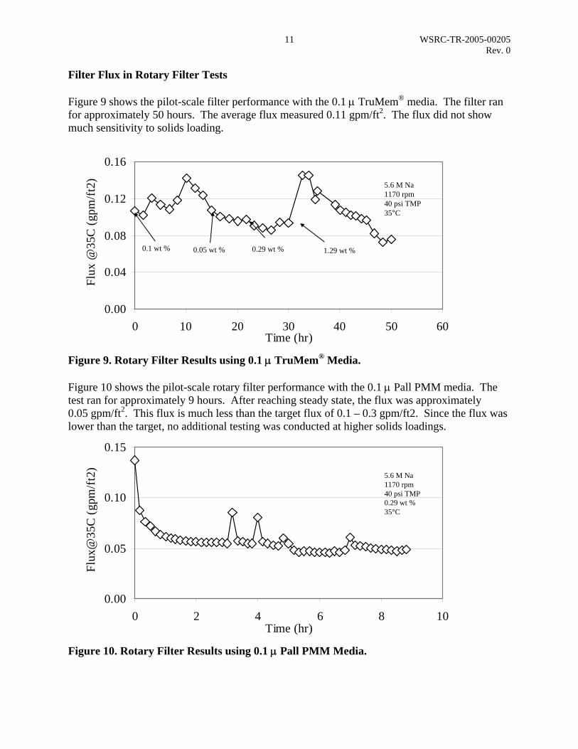
Filter Flux in Rotary Filter Tests Figure 9 shows the pilot-scale filter performance with the 0.1 µ TruMem® media. The filter ran for approximately 50 hours. The average flux measured 0.11 gpm/ft2. The flux did not show much sensitivity to solids loading.
0.00
0.04
0.08
0.12
0.16
0 10 20 30 40 50 60Time (hr)
Fl
ux @
35C
(gpm
/ft2)
5.6 M Na1170 rpm40 psi TMP35°C
0.1 wt % 0.05 wt % 0.29 wt % 1.29 wt %
Figure 9. Rotary Filter Results using 0.1 µ TruMem® Media. Figure 10 shows the pilot-scale rotary filter performance with the 0.1 µ Pall PMM media. The test ran for approximately 9 hours. After reaching steady state, the flux was approximately 0.05 gpm/ft2. This flux is much less than the target flux of 0.1 – 0.3 gpm/ft2. Since the flux was lower than the target, no additional testing was conducted at higher solids loadings.
0.00
0.05
0.10
0.15
0 2 4 6 8 10Time (hr)
Fl
ux@
35C
(gpm
/ft2)
5.6 M Na1170 rpm40 psi TMP0.29 wt %35°C
Figure 10. Rotary Filter Results using 0.1 µ Pall PMM Media.
12 WSRC-TR-2005-00205 Rev. 0
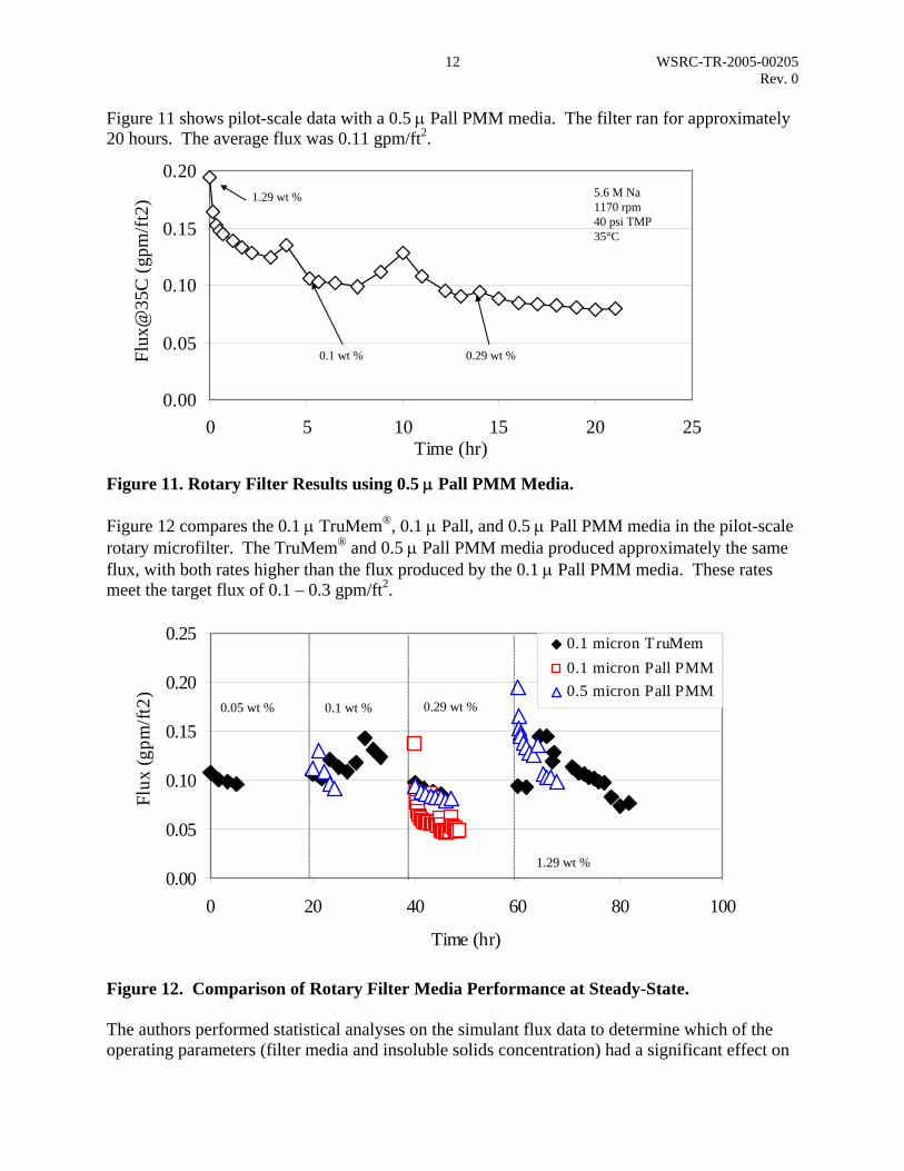
Figure 11 shows pilot-scale data with a 0.5 µ Pall PMM media. The filter ran for approximately 20 hours. The average flux was 0.11 gpm/ft2.
0.00
0.05
0.10
0.15
0.20
0 5 10 15 20 25Time (hr)
Fl
ux@
35C
(gpm
/ft2)
5.6 M Na1170 rpm40 psi TMP35°C
1.29 wt %
0.1 wt % 0.29 wt %
Figure 11. Rotary Filter Results using 0.5 µ Pall PMM Media. Figure 12 compares the 0.1 µ TruMem®, 0.1 µ Pall, and 0.5 µ Pall PMM media in the pilot-scale rotary microfilter. The TruMem® and 0.5 µ Pall PMM media produced approximately the same flux, with both rates higher than the flux produced by the 0.1 µ Pall PMM media. These rates meet the target flux of 0.1 – 0.3 gpm/ft2.
0.00
0.05
0.10
0.15
0.20
0.25
0 20 40 60 80 100
Time (hr)
Fl
ux (g
pm/ft
2)
0.1 micron TruMem0.1 micron Pall PMM0.5 micron Pall PMM
0.05 wt % 0.1 wt % 0.29 wt %
1.29 wt %
Figure 12. Comparison of Rotary Filter Media Performance at Steady-State. The authors performed statistical analyses on the simulant flux data to determine which of the operating parameters (filter media and insoluble solids concentration) had a significant effect on

13 WSRC-TR-2005-00205 Rev. 0
filter flux. The analyses were performed (with JMP® software) by developing a model to calculate the flux as a function of filter media and insoluble solids The analysis of variance table (see Table 2) shows the basic statistical calculations for a linear model. Since the authors conducted 111 tests and one degree of freedom is used to calculate the mean, 110 degrees of freedom are available to calculate the variance. Since the model contains four terms, it uses 3 degrees of freedom. The remaining 107 degrees of freedom were used to calculate the error. The JMP software calculated the variance in the flux due to the model and the variance in the flux due to random error. Each variance was divided by the number of degrees of freedom, and the ratio of the mean variances was calculated to produce an F ratio. The software calculated the probability of obtaining a greater F value by chance alone. If the probability is less than 0.05, the model contains at least one significant regression factor (with 95% confidence). Table 2. Statistical Analysis of Pilot-Scale Rotary Filter Data Comparison of 0.1 µ TruMem®, 0.1 µ Pall PMM, and 0.5 µ Pall PMM Media Observations (or Sum Wgts) 111Analysis of Variance Source DF Sum of Squares Mean Square F RatioModel 3 0.0759 0.025317 98.4Error 107 0.0275 0.000257 Prob > FC. Total 110 0.1034 <.0001Effect Tests Source Nparm DF Sum of Squares F Ratio Prob > FMedia 2 2 0.04914 95.6 <.0001TIS 1 1 0.00167 6.5 0.0120Media Least Squares Means Table Level Mean0.1 µ TruMem 0.1060.1 µ Pall PMM 0.0560.5 µ Pall PMM 0.109 Comparison of 0.1 µ TruMem® and 0.5 µ Pall PMM Media Observations (or Sum Wgts) 58Analysis of Variance Source DF Sum of Squares Mean Square F RatioModel 2 0.00179 0.000894 2.18Error 55 0.02258 0.000411 Prob > FC. Total 57 0.02437 0.123Effect Tests Source Nparm DF Sum of Squares F Ratio Prob > FMedia 1 1 0.0000728 0.177 0.675TIS 1 1 0.0016796 4.091 0.048Media Least Squares Means Table Level Mean0.1 µ TruMem 0.1060.5 µ Pall PMM 0.109

14 WSRC-TR-2005-00205 Rev. 0
The effects test table shows the results of tests conducted to determine whether the individual effects are zero. Continuous effects have one parameter, and nominal effects have one less parameter than the number of levels. Ordinarily the degrees of freedom and the number of parameters are the same. The sum of squares is the variance due to the effect in the model. The F ratio is the ratio of the mean square for the effect divided by the mean square for the error. Prob > F is the probability that the null hypothesis is true (i.e., the variance measured is due to random error). Values less than 0.05 indicate the effect is statistically significant (with 95% confidence). Table 2 shows the statistical analysis of the pilot-scale filter data. The analysis shows that the 0.1 µ TruMem® and 0.5 µ Pall PMM media produce the same filter flux, which is greater than the flux produced by the 0.1 µ Pall PMM media. Since the Prob > F is close to 0.05, the filter flux is not a strong function of solids loading. Since higher flux would increase the throughput of the SCIX process, the authors performed an additional test with the Pall PMM M100 media (1.0 µ nominal). Figures 13 - 15 show pilot-scale results with 0.1 µ TruMem® media, 0.1 µ Pall PMM media, 0.5 µ Pall PMM media, and 1.0 µ Pall PMM media at 0.06 wt %. The plot also shows data collected with the 0.1 µ TruMem® and 0.1 µ Pall PMM media at the University of South Carolina.8 The 0.5 µ Pall PMM media and the 0.1 µ TruMem® media produced the highest flux at all solids loadings.
0.00
0.04
0.08
0.12
0.16
0 2 4 6 8 10
Time (hr)
Fl
ux (g
pm/ft
2)
0.1 micron Pall-USC0.1 micron TruMem-USC0.1 micron TruMem-ACTL0.5 micron Pall-ACTL1.0 micron Pall-ACTL
0.06 wt %
Figure 13. Comparison of Media in 3-Disk Rotary Filter at 0.06 wt %.

15 WSRC-TR-2005-00205 Rev. 0
0.00
0.04
0.08
0.12
0.16
0 2 4 6 8 10Time (hr)
Fl
ux (g
pm/ft
2)
0.1 micron Pall-USC0.1 micron TruMem-USC0.1 micron Pall-ACTL0.1 micron TruMem-ACTL0.5 micron Pall-ACTL1.0 micron Pall-ACTL
0.29 wt %
Figure 14. Comparison of Media in 3-Disk Rotary Filter at 0.29 wt %.
0.00
0.04
0.08
0.12
0.16
0 2 4 6 8 10Time (hr)
Fl
ux (g
pm/ft
2)
0.1 micron Pall-USC0.1 micron TruMem-USC0.1 micron TruMem-ACTL0.5 micron Pall-ACTL1.0 micron Pall-ACTL
1.29 wt %
Figure 15. Comparison of Media in 3-Disk Rotary Filter at 1.29 wt %. The TruMem® media produced higher flux in the current tests than in previous tests conducted at the University of South Carolina. The reason for the difference is that the media in the University of South Carolina test had previously been used, and the media in the current test was new. The 0.1 µ Pall PMM media produced approximately the same flux in the current tests as in the previous tests. The media was new in both tests. Table 3 shows the statistical analysis of the pilot-scale filter data. The analysis shows that the 0.1 µ TruMem® and 0.5 µ Pall PMM media produce higher flux than the 0.1 or 1.0 µ Pall PMM media. Since the Prob > F is > 0.05, the filter flux is not a function of solids loading.
16 WSRC-TR-2005-00205 Rev. 0
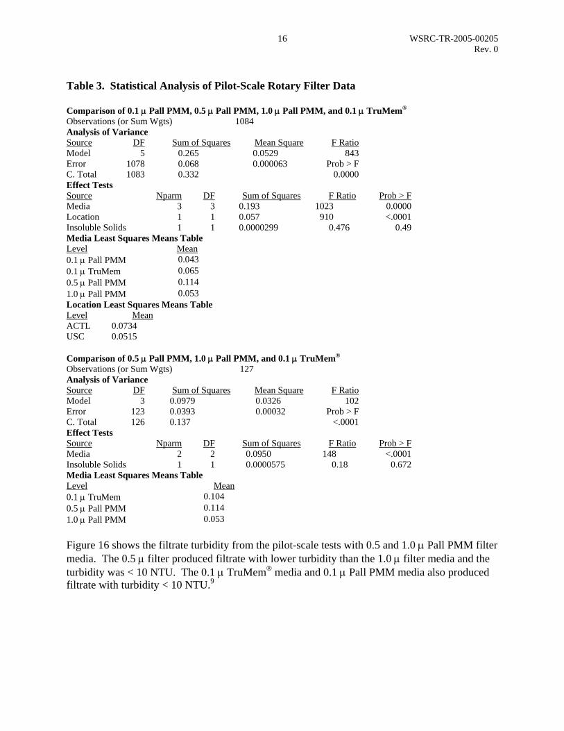
Table 3. Statistical Analysis of Pilot-Scale Rotary Filter Data Comparison of 0.1 µ Pall PMM, 0.5 µ Pall PMM, 1.0 µ Pall PMM, and 0.1 µ TruMem®
Observations (or Sum Wgts) 1084Analysis of Variance Source DF Sum of Squares Mean Square F RatioModel 5 0.265 0.0529 843Error 1078 0.068 0.000063 Prob > FC. Total 1083 0.332 0.0000Effect Tests Source Nparm DF Sum of Squares F Ratio Prob > F Media 3 3 0.193 1023 0.0000 Location 1 1 0.057 910 <.0001 Insoluble Solids 1 1 0.0000299 0.476 0.49 Media Least Squares Means Table Level Mean 0.1 µ Pall PMM 0.043 0.1 µ TruMem 0.065 0.5 µ Pall PMM 0.114 1.0 µ Pall PMM 0.053 Location Least Squares Means Table Level Mean ACTL 0.0734 USC 0.0515 Comparison of 0.5 µ Pall PMM, 1.0 µ Pall PMM, and 0.1 µ TruMem® Observations (or Sum Wgts) 127Analysis of Variance Source DF Sum of Squares Mean Square F RatioModel 3 0.0979 0.0326 102Error 123 0.0393 0.00032 Prob > FC. Total 126 0.137 <.0001Effect Tests Source Nparm DF Sum of Squares F Ratio Prob > F Media 2 2 0.0950 148 <.0001 Insoluble Solids 1 1 0.0000575 0.18 0.672 Media Least Squares Means Table Level Mean 0.1 µ TruMem 0.104 0.5 µ Pall PMM 0.114 1.0 µ Pall PMM 0.053 Figure 16 shows the filtrate turbidity from the pilot-scale tests with 0.5 and 1.0 µ Pall PMM filter media. The 0.5 µ filter produced filtrate with lower turbidity than the 1.0 µ filter media and the turbidity was < 10 NTU. The 0.1 µ TruMem® media and 0.1 µ Pall PMM media also produced filtrate with turbidity < 10 NTU.9

17 WSRC-TR-2005-00205 Rev. 0
0.1
1
10
100
1000
0 5 10 15 20 25Sample Number
T
urbi
dity
(NTU
) 0.5 micron
1.0 micron
system opened to inspect disks
Figure 16. Comparison of 0.5 and 1.0 µ Media Turbidity in 3-Disk Rotary Filter. Reliability A determining factor in the media selection is the anticipated durability. The Pall PMM media is recommended over the TruMem® even though the TruMem® consistently produced higher flux rates at the same pore size. This recommendation is based on two instances of tearing in the TruMem® media. The first occurrence was during a back-pressure test on the welded filter disks. Disks fabricated using the Pall PMM media and the TruMem® media were subject to a pressure internal to the disk as part of a potential accident scenario. The tests resulted in a deformation of the Pall PMM media but the integrity of the disk and media were maintained. The TruMem® media tore in three places from the center of the disk towards the outer edge. The second incident was a small tear in the TruMem® media during operation in the rotary filter. Examination of the damage indicated that a piece of material worked under the membrane and pushed through during operation. The damage was discovered after unusually high turbidity results persisted. Researchers stopped the testing, inspected the disks and discovered the damage. No feed breakthrough due to a compromise of media integrity occurred in any pilot-scale rotary filter testing with the Pall PMM media. Personnel involved in welding the rotary filter disks indicated that the Pall PMM media was easier to weld than the Mott or TruMem® media.
18 WSRC-TR-2005-00205 Rev. 0
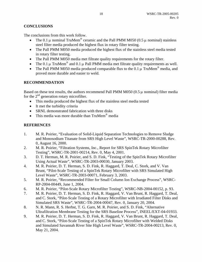
CONCLUSIONS The conclusions from this work follow.
• The 0.1 µ nominal TruMem® ceramic and the Pall PMM M050 (0.5 µ nominal) stainless steel filter media produced the highest flux in rotary filter testing.
• The Pall PMM M050 media produced the highest flux of the stainless steel media tested in rotary filter testing.
• The Pall PMM M050 media met filtrate quality requirements for the rotary filter. • The 0.1 µ TruMem® and 0.1 µ Pall PMM media met filtrate quality requirements as well. • The Pall PMM M050 media produced comparable flux to the 0.1 µ TruMem® media, and
proved more durable and easier to weld. RECOMMENDATION Based on these test results, the authors recommend Pall PMM M050 (0.5 µ nominal) filter media for the 2nd generation rotary microfilter.
• This media produced the highest flux of the stainless steel media tested • It met the turbidity criteria • SRNL demonstrated fabrication with three disks • This media was more durable than TruMem® media
REFERENCES 1. M. R. Poirier, “Evaluation of Solid-Liquid Separation Technologies to Remove Sludge
and Monosodium Titanate from SRS High Level Waste”, WSRC-TR-2000-00288, Rev. 0, August 16, 2000.
2. M. R. Poirier, “Filtration Systems, Inc., Report for SRS SpinTek Rotary Microfilter Testing”, WSRC-TR-2001-00214, Rev. 0, May 4, 2001.
3. D. T. Herman, M. R. Poirier, and S. D. Fink, “Testing of the SpinTek Rotary Microfilter Using Actual Waste”, WSRC-TR-2003-00030, January 2003.
4. M. R. Poirier, D. T. Herman, S. D. Fink, R. Haggard, T. Deal, C. Stork, and V. Van Brunt, “Pilot-Scale Testing of a SpinTek Rotary Microfilter with SRS Simulated High Level Waste”, WSRC-TR-2003-00071, February 3, 2003.
5. M. R. Poirier, “Recommended Filter for Small Column Ion Exchange Process”, WSRC-RP-2004-00449, June 1, 2004.
6. M. R. Poirier, “Pilot-Scale Rotary Microfilter Testing”, WSRC-NB-2004-00152, p. 93. 7. M. R. Poirier, D. T. Herman, S. D. Fink, R. Haggard, V. Van Brunt, R. Haggard, T. Deal,
and C. Stork, “Pilot-Scale Testing of a Rotary Microfilter with Irradiated Filter Disks and Simulated SRS Waste”, WSRC-TR-2004-00047, Rev. 0, January 20, 2004.
8. N. R. Mann, R. S. Herbst, T. G. Garn, M. R. Poirier, and S. D. Fink, “Alternative Ultrafiltration Membrane Testing for the SRS Baseline Process”, INEEL/EXT-04-01933.
9. M. R. Poirier, D. T. Herman, S. D. Fink, R. Haggard, V. Van Brunt, R. Haggard, T. Deal, and C. Stork, “Pilot-Scale Testing of a SpinTek Rotary Microfilter with Welded Disks and Simulated Savannah River Site High Level Waste”, WSRC-TR-2004-00213, Rev. 0, May 21, 2004.

19 WSRC-TR-2005-00205 Rev. 0
10. M. R. Poirier and D. T. Hobbs, “Filterability of Monosodium Titanate Supplied by Blue Grass Chemical Specialties”, WSRC-TR-2004-00214, April 13, 2004.
11. M. R. Poirier, “Improving the Filtration of Sludge/Monosodium Titanate Slurries by the Addition of Flocculants”, WSRC-TR-2001-00175, March 27, 2001.
12. T. G. Garn, N. R. Mann, R. S. Herbst, and T. A. Todd, “Experimental Comparison of Mott, GKN, Pall, and Graver Ultrafiltration Membranes using Envelope A (AN-105) and Envelope D (AZ-101) Hanford Simulants,” INEEL/EXT-03-00887, July 2003.
13. M. C. Porter, Ed., Handbook of Industrial Membrane Technology, Park Ridge: Noyes, 1990, p. 77.


Distribution WSRC-TR-2005-00205, Rev 0
R. A. Adams 241-162H, Rm. 4 (E) D. B. Little 703-H, Rm. 3 (E) J. W. Barber 704-2H, Rm. 197 (E) S. R. Loflin 773-41A, Rm. 223 (E) J. L. Barnes 704-S, Rm. 19 (E) N. P. Malik 704-26F, Rm. 11 (E) M. J. Barnes 773-A, Rm. B-132 (E) J. C. Marra 773-42A, Rm. 173 (E) W. M. Barnes 704-56H, Rm. 164 (E) D. J. Martin 703-H, Rm. 84 (E) S. M. Blanco 766-H. Rm. 2434 (E) K. B. Martin 773-42A, Rm. 14 (E) L. R. Bragg 766-H, Rm. 2434 (E) C. J. Martino 735-11A, Rm. 121 (E) T. E. Britt 742-4G, Rm. 3 (E) H. L. Bui 742-4G, Rm. 3 (E) G. J. Matis 766-H, Rm. 1066F (E) S. G. Campbell 703-H, Rm. 107 (E) D. Maxwell 766-H, Rm. 2231 (E) L. Carey 766-H, Rm. 2005A (E) D. J. McCabe 73-42-A, Rm. 153 (E) J. T. Carter 703-H, Rm 122 (E) J. W. McCullough 766-H, Rm. 2411 (E) W. D. Clark 766-H, Rm. 2412 (E) L. T. McGuire 766-H, Rm. 2441 (E) S. L. Clifford 766-H, Rm. 2443 (E) M. S. Miller 772-7B, Rm. 6 (E) J. J. Connelly 773-41A, Rm. 231 (E) C. A. Nash 773-42A, Rm. 182 (E) D. T. Conrad 766-H, Rm. 2007 (E) L. M. Nelson 773-43A, Rm. 222 (E) D. R. Cox 730-2B, Rm. 118 (E) M. A. Norato 704-27S, Rm. 6 (E) A. D. Cozzi 773-43A, Rm. 218 (E) M. R. Norton 66-H, Rm. 2002 (E) C. L. Crawford 773-41A, Rm. 180 (E) J. E. Occhipinti 704-S, Rm. 18 (E) D. A. Crowley 773-A, Rm. A-262 (E) L. D. Olson 703-H, Rm. 5 (E) N. R. Davis 766-H, Rm. 1006 (E) L. M. Papouchado 773-A, Rm. A-263 (P) W. B. Dean 766-H, Rm. 2243 (E) T. B. Peters 773-42A, Rm. 128 (E) V. G. Dickert 703-H, Rm. 4 (E) J. A. Pike 703-H, Rm. 99 (E) C. L. Donahue 241-162H, Rm. 6 (E) M. R. Poirier 773-42A, Rm. 123 (E) M. D. Drumm 766-H, Rm. 2050 (E) S. H. Reboul 703-H, Rm. 84 (E) M. C. Duff 773-43A, Rm. 217 (E) T. R. Reynolds 704-S, Rm. 65 (E) C. R. Dyer 766-H, Rm. 2426 (E) M.A. Rios-Armstrong 766-H, Rm 2054 (E) R. E. Eibling 999-W, Rm. 335 (E) S. J. Robertson 766-H, Rm. 2500 (P) G. N. Eide 241-121H, Rm. 6 (E) B. C. Rogers 766-H, Rm. 2008 (E) H. H. Elder 703-H, Rm. 95 (E) R. A. Runnels 766-H, Rm. 2011 (E) S. D. Fink 773-A, Rm. B-112 (E, P) P. J. Ryan 704-61S, Rm. 6 (E) F. F. Fondeur 773-A, Rm. B-124 (E) E. Saldivar 766-H, Rm. 2004 (E) R. C. Fowler 703-H, Rm. 98 (E) S. C. Shah 766-H, Rm. 2037 (E) L. M. Fox 703-H, Rm. 3 (E) D. C. Sherburne 704-S, Rm. 18 (E) M.W. Geeting 766-H, Rm. 2035 (E) T. J. Spears 766-H, Rm. 2015 (E) B. A. Gifford 766-H, Rm. 1066D (E) R. H. Spires 766-H, Rm. 2003 (E) A. P. Giordano 703-H, Rm 79 (E) M. E. Stallings 773-A, Rm. B-117 (E) J. C. Griffin 773-A, rm. A-231 (E) W. E. Stevens 773-A, Rm. A-261 (E) B. A. Hamm 766-H, Rm. 2237 (E) S. J. Strohmeier 766-H, Rm. 2022 (E) H. D. Harmon 766-H, Rm. 2014 (P) S. G. Subosits 766-H, Rm. 2052 (E) K. D. Harp 755-H, Rm. 1066B (E) P. C. Suggs 766-H, Rm. 2436 (E) E. W. Harrison 766-H, Rm. 2034 (E) G. A. Taylor 703-H, Rm. 96 (E) K. A. Hauer 703-H, Rm. 11 (E) S. A. Thomas 766-H, Rm. 2016 (E) D. T. Herman 735-11A, Rm. 104 (E) P. J. Valenti 730-4B, Rm. 2062 (E) P. J. Hill 766-H, Rm. 1066C (E) W. B. Van-Pelt 704-S, Rm. 16 (E) R. N. Hinds 766-H, Rm. 2430 (E) D. D. Walker 773-A, Rm. B-124 (E) D. T. Hobbs 773-A, Rm. B-117 (E) A. O. Waring 766-H, Rm. 2423 (E) E. W. Holtzscheiter 773-A, Rm. A-230 (E) F. A. Washburn 766-H, Rm. 2054 (E) C. M. Jantzen 773-A, Rm. B-104 (E) V. B. Wheeler 766-H, Rm. 2438 (E) R. T. Jones 766-H, Rm. 2463 (E) G. G. Wicks 773-A, Rm. B-129 (E) E. T. Ketusky 703-H, Rm. 83 (E ) W. R. Wilmarth 773-42A, Rm. 171 (E) D. P. Lambert 773-A, Rm. B-132 (E) G. C. Whinship 766-H, Rm. 2024 (E) C. A. Lanigan 766-H, Rm. 2440B (E) LWP File 773-42A (E, P) C. A. Langton 773-43A, Rm. 219 (E) STI 703-43A (E) (P 3 copies) T. T. Le 766-H, Rm. 2237 (E) R. K. Leugemors 766-H, (E) *Our standard distribution format is electronic unless otherwise requested (E) Electronic (P) Paper Mail