rotary machining
TRANSCRIPT

8/3/2019 Rotary Machining
http://slidepdf.com/reader/full/rotary-machining 1/9
OverviewThis project is set up for Rotary Machining a mesh 3D part. In this
demo we will show you how to take one of the created ArtCAM
parts from the 2006 User Group and unwrap the STL mesh file into
an ArtCAM file. This will allow you to use ArtCAM to wrap the
part in order to create a rotary toolpath.
Importing the Mesh for Unwrapping
1. Open an ArtCAM file 24 X 5
2. Zero the part in the middle of the White Model Area (this
is very important for unwrapping)
3. Once ArtCAM opens a new project navigate to help Pull
Down Menu4. Choose Import-3D Model for Unwrapping
• See figure 1 for reference on the Import 3D Model for
Unwrapping location.
Rotary Machining
85042189.doc 1

8/3/2019 Rotary Machining
http://slidepdf.com/reader/full/rotary-machining 2/9
Figure 1
5. Select the Ball and Claw.stl file from the Rotary folder from the prep folder and click Open
6. Click Center in the Paste 3D Model window
Change the Z Position to be -2.0” and click Apply
7. From the 3D Model Unwrapping window (left Assistant
Window)
Set the Unwrapping Cylinder Diameter to be 0.75
Set the Border Width to be 0.75
Click Create New Model
• Use Figure 2 as a guide to set up this mesh for
Unwrapping.
• Remember to not click Paste from the Paste 3D Model
window as this will only Paste the Mesh into ArtCAM
and not allow you to Unwrap it.
85042189.doc 2
8/3/2019 Rotary Machining
http://slidepdf.com/reader/full/rotary-machining 3/9
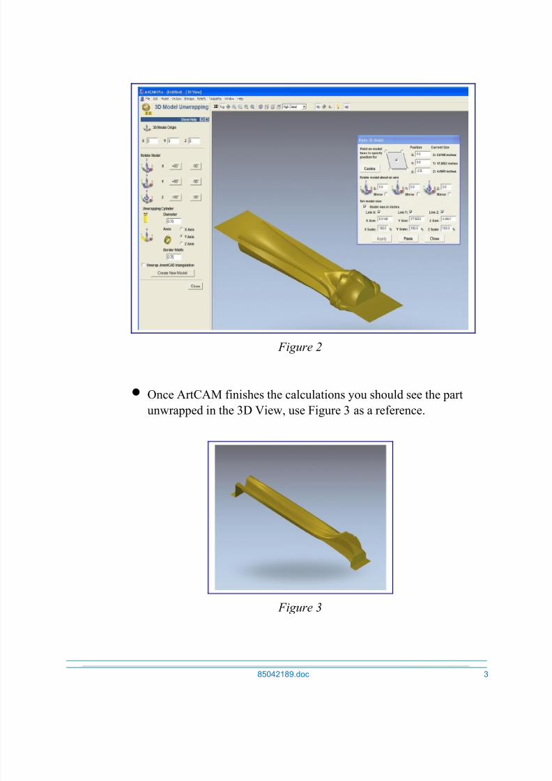
Figure 2
• Once ArtCAM finishes the calculations you should see the part
unwrapped in the 3D View, use Figure 3 as a reference.
Figure 3
85042189.doc 3

8/3/2019 Rotary Machining
http://slidepdf.com/reader/full/rotary-machining 4/9
8. Next, to view the part wrapped (as it was imported) we
need to navigate to the Relief Pull Down menu
9. Extend the relief Pull Down menu and choose Create
Ring
10.The Create Ring window will appear, select Wrap X andOK
• Once the part has been wrapped, it will appear in the
3D View. Use Figure 4 as a reference. Notice the
Inner Diameter that we have set to 0.75”.
Figure 4
• When viewing this part we can see that this part in
particular would not be the best part to apply a rotary
axis toolpath to. The reason being is we lost all thedetail from the side claws from the original part.
11.Close this ArtCAM file
12.Open a new ArtCAM file 24 X 5
13.Zero the part in the middle of the White Model Area (this
is very important for unwrapping)
85042189.doc 4

8/3/2019 Rotary Machining
http://slidepdf.com/reader/full/rotary-machining 5/9
14.Once ArtCAM opens a new project navigate to help Pull
Down Menu
15.Choose Import-3D Model for Unwrapping
16.Select the CabrioleLeg.stl file from the Rotary folder and
click Open
17.Click Center in the Paste 3D Model window
Change the Z Position to be -2.25” and click Apply
18.From the 3D Model Unwrapping window (left Assistant
Window)
Set the Unwrapping Cylinder Diameter to be 0.75
Set the Border Width to be 0.75
Click Create New Model
• At this point ArtCAM will calculate the Unwrapping
calculations and create a new ArtCAM file with this
mesh unwrapped. See Figure 5.
Figure 5
19.Next, to view the part wrapped (as it was imported) we
need to navigate to the Relief Pull Down menu
85042189.doc 5
8/3/2019 Rotary Machining
http://slidepdf.com/reader/full/rotary-machining 6/9
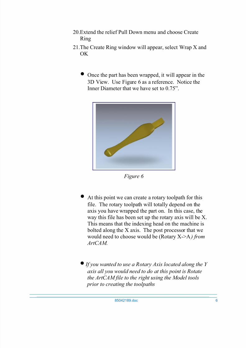
20.Extend the relief Pull Down menu and choose Create
Ring
21.The Create Ring window will appear, select Wrap X and
OK
• Once the part has been wrapped, it will appear in the
3D View. Use Figure 6 as a reference. Notice the
Inner Diameter that we have set to 0.75”.
Figure 6
• At this point we can create a rotary toolpath for this
file. The rotary toolpath will totally depend on the
axis you have wrapped the part on. In this case, the
way this file has been set up the rotary axis will be X.
This means that the indexing head on the machine is
bolted along the X axis. The post processor that we
would need to choose would be (Rotary X->A ) from
ArtCAM.
• If you wanted to use a Rotary Axis located along the Y
axis all you would need to do at this point is Rotatethe ArtCAM file to the right using the Model tools
prior to creating the toolpaths
85042189.doc 6

8/3/2019 Rotary Machining
http://slidepdf.com/reader/full/rotary-machining 7/9
85042189.doc 7

8/3/2019 Rotary Machining
http://slidepdf.com/reader/full/rotary-machining 8/9
Machining the Rotary Part
• ArtCAM rotary toolpaths are created when the ArtCAM Relief is wrapped in either the X or Y axis.
1. Open the Toolpath window and choose Machine Relief
2. From the 2D View Select the Vector Outline of the
cabriole leg.
3. From the Toolpath window choose the Machine Relief
toolpath strategy
4. Set the toolpath up as follows:
Area to Machine = Whole Model
Strategy = Raster 90 degrees
Machine Safe Z = 0.25”
Tool = 0.25” Ballnose Endmill (Set tool parameters as
desired)
Do not set the Material (Rotary tools do not use the
Material Thickness)
Calculate Now and Close
• Figure 7 shows the created rotary toolpath.
85042189.doc 8

8/3/2019 Rotary Machining
http://slidepdf.com/reader/full/rotary-machining 9/9
Figure 7
5. Save the toolpath out of ArtCAM with a Rotary Toolpath
Postprocessor
6. Click Save Toolpaths and choose Rotary X->B
Figure 8
• Included on the ArtCAM User Group DVD for 2006 is
a Rotary Axis Machining tutorial showing how to set
up an ArtCAM file for Rotary Machining from scratch. This includes an ArtCAM relief file and
explains how to set up the file for machining.
85042189.doc 9