rosewood court geotechnical report pdf - redmond.gov
TRANSCRIPT

GEOTECHNICAL REPORT
Rosewood Court 10428 and 10612 – 134th Avenue NE
Redmond, Washington
Project No. T-8143
Prepared for:
D. R. Horton Kirkland, Washington
May 1, 2019 5th Revision April 7, 2020

May 1, 2019 5th Revision April 7, 2020
Project No. T-8143
Ms. Raelyn Hulquist D.R. Horton 11241 Slater Avenue NE, Suite 200 Kirkland, Washington 98033
Subject: Geotechnical Report Rosewood Court 10428 and 10612 – 134th Avenue NE Redmond, Washington
Dear Ms. Hulquist:
As requested, we have conducted a geotechnical engineering study for the subject project. The attached report presents our findings and recommendations for the geotechnical aspects of project design and construction.
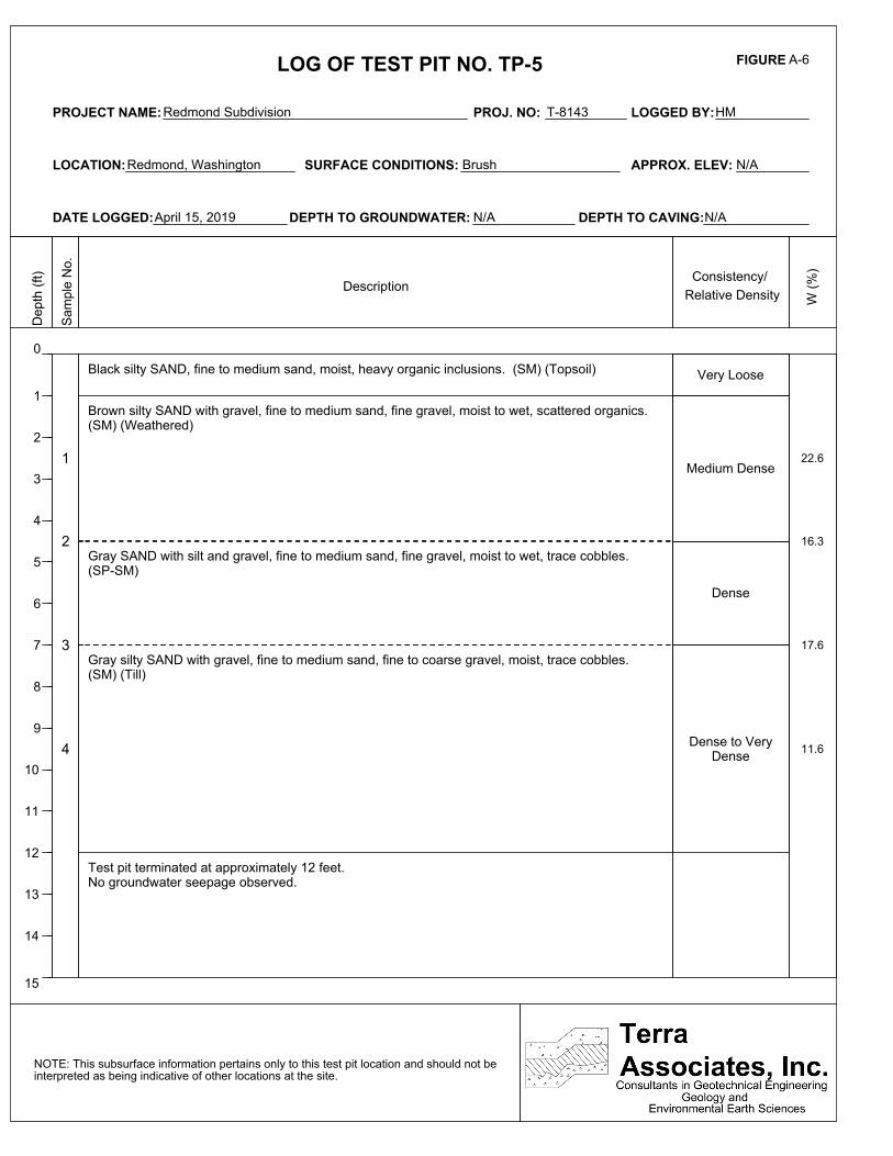
Our field exploration indicates that the soil observed in the test pits generally consist of approximately 11 to 18 inches of topsoil overlying 3 to 4.5 feet of medium dense to dense silty sand with gravel (weathered till) overlying dense to very dense silty sand with gravel (unweathered till) to the termination of the test pits. There were two exceptions to this general condition. At Test Pits TP-6 and TP-13, we observed approximately one to one- and one-half feet of loose to medium dense organic fill material overlying the native soils. At Test Pits TP-1 and TP-5, we observed an approximately two-foot layer of medium dense to dense sand with silt and gravel between the upper silty sand with gravel and lower silty sand with gravel at a depth of about four- and one-half feet.
The upper soil conditions observed in the test borings are generally consistent with those observed in the test pits. The very dense unweathered glacial till material is present to approximately 43 feet below current site grades. Underlying the unweathered glacial till is advance outwash which is composed of layers of very dense to hard sand, silty sand, and silt to the termination of the test borings.
Minor groundwater seepage was observed in 7 of the 15 test pits at depths ranging from 4 to 7 feet below existing site grades and the groundwater was also observed in both of the test borings between 78 and 88 feet below current site grades.
12220 113th Avenue NE, Ste. 130, Kirkland, Washington 98034 Phone (425) 821‐7777 • Fax (425) 821‐4334


TABLE OF CONTENTS
Page No.
1.0 Project Description ........................................................................................................... 1 2.0 Scope of Work ................................................................................................................. 1 3.0 Site Conditions ................................................................................................................. 2 3.1 Surface ................................................................................................................ 2 3.2 Subsurface ........................................................................................................... 2 3.3 Groundwater ....................................................................................................... 3 3.4 Geologic Hazards ................................................................................................ 3 3.4.1 Erosion Hazard Areas ................................................................................ 3 3.4.2 Landslide Hazard Areas ............................................................................. 4
3.4.3 Seismic Hazard Areas ................................................................................ 5 3.5 Seismic Design Parameters ................................................................................. 6
4.0 Discussion and Recommendations ................................................................................... 6 4.1 General ................................................................................................................ 6 4.2 Site Preparation and Grading .............................................................................. 6
4.3 Relative Slope Stability ....................................................................................... 7 4.4 Excavations ......................................................................................................... 8 4.5 Foundation Support ............................................................................................. 9 4.6 Floor Slab-on-Grade ......................................................................................... 10
4.7 Stormwater Facilities ........................................................................................ 10 4.8 Infiltration Feasibility ....................................................................................... 11
4.9 Drainage ............................................................................................................ 12 4.10 Utilities .............................................................................................................. 12
4.11 Pavement ........................................................................................................... 12 5.0 Additional Services ........................................................................................................ 13 6.0 Limitations ..................................................................................................................... 13
Figures
Vicinity Map ......................................................................................................................... Figure 1 Exploration Location Plan..................................................................................................... Figure 2
Typical Wall Drainage Detail ............................................................................................... Figure 3
Appendices
Field Exploration and Laboratory Testing ....................................................................... Appendix A Slope Stability Results...................................................................................................... Appendix B

Geotechnical Report Rosewood Court
10428 and 10612 – 134th Avenue NE Redmond, Washington
1.0 PROJECT DESCRIPTION
The project consists of developing the approximately 10.5-acre site with 51 residential building lots, stormwater facilities, associated access, and utilities. Based on the grading plans prepared by LDC, dated April 3, 2020, cuts and fills to achieve building lot and roadway elevations will range from one to five feet. Site stormwater will be collected and directed to a below-grade stormwater detention vault located in the southeast portion of the site. There are two discharge points for the site stormwater. One is at the top of the steep slope on the eastern side of the property and the other is near the toe of the steep slope in the southeastern portion of the site. These points are to allow the water to follow the natural drainage paths.
The structures constructed on the lots are expected to be two- to three-story wood-frame buildings, with main floors framed over a crawlspace with attached garages constructed at grade. Foundation loads should be relatively light, in the range of 4 to 6 kips per foot for bearing walls and 50 to 75 kips for isolated columns.
The recommendations in the following sections of this report are based on the design discussed above. If actual features vary or changes are made, we should review the plans in order to modify our recommendations, as required. We should review final design drawings and specifications to verify that our recommendations have been properly interpreted and incorporated into the project design.
2.0 SCOPE OF WORK
Our work was completed in accordance with our authorized proposal, dated January 8, 2019. Accordingly, on April 8, 9, and 15, 2019, we observed soil and groundwater conditions at 2 test borings drilled to a maximum depth of approximately 101 feet below existing site grades and 15 test pits excavated to depths of approximately 9 to 13 feet below existing site grades. Using this data along with laboratory testing, we performed analyses to develop geotechnical recommendations for project design and construction. Specifically, this report addresses the following:
Soil and groundwater conditions.
Geologic Hazards per the Redmond Zoning Code (RZC).
Seismic design parameters per the 2018 International Building Code (IBC).
Site preparation and grading.
Relative slope stability.
Excavations

May 1, 2019 5th Revision April 7, 2020
Project No. T-8143
Page No. 2
Foundation support.
Floor slab-on-grade support.
Stormwater facilities.
Infiltration feasibility.
Drainage
Utilities
Pavement
It should be noted that recommendations outlined in this report regarding drainage are associated with soil strength, design earth pressures, erosion, and stability. Design and performance issues with respect to moisture as it relates to the structure environment are beyond Terra Associates’ purview. A building envelope specialist or contractor should be consulted to address these issues, as needed.
3.0 SITE CONDITIONS
3.1 Surface
The project site consists of 3 tax parcels totaling approximately 10.5 acres located at 10428 and 10612 – 134th Avenue NE in Redmond, Washington. The approximate site location is shown on Figure 1.
The site is currently undeveloped and predominately covered with brush, grass, and weeds. There are pockets of mature trees in the northwest, southwest, and east-central portions of the site. Site topography is generally flat, with a slight slope from west to east that transitions to a steep slope near the eastern and a portion of the northern property line. The site has an overall relief of approximately 15 feet. The off-site steep slopes have an overall relief of approximately 230 feet. The eastern 100 feet of the site is within a Puget Sound Energy (PSE) easement that includes overhead power lines.
3.2 Subsurface
In general, the soil conditions at the site consisted of approximately 11 to 18 inches of topsoil overlying 3 to 4.5 feet of medium dense to dense silty sand with gravel (weathered till) overlying dense to very dense silty sand with gravel (unweathered till) to the termination of the test pits. There were two exceptions to this general condition. At Test Pits TP-6 and TP-13, we observed approximately one to one- and one-half feet of loose to medium dense organic fill material overlying the native soils. At Test Pits TP-1 and TP-5, we observed an approximately two-foot layer of medium dense to dense sand with silt and gravel between the upper silty sand with gravel and lower silty sand with gravel at a depth of about four- and one-half feet.

May 1, 2019 5th Revision April 7, 2020
Project No. T-8143
Page No. 3
The upper soil conditions observed in the test borings are generally consistent with those observed in the test pits. The very dense, unweathered glacial till material is present to approximately 43 feet below current site grades. Underlying the unweathered glacial till is advance outwash, which is composed of layers of very dense to hard sand, silty sand, and silt to the termination of the test borings.
The Geologic Map of the Kirkland Quadrangle, Washington by J.P. Minard (1983), shows the site soils mapped as Till (Qvt). The native soils observed in the test pits and test borings are generally consistent with this mapped description.
The preceding discussion is intended to be a general review of the soil conditions encountered. For more detailed descriptions, please refer to the Test Pit and Test Boring Logs in Appendix A.
3.3 Groundwater
We observed minor groundwater seepage in 7 of the 15 test pits at depths ranging from 4 to 7 feet below existing site grades. The groundwater seepage was primarily observed near the contact between the upper weathered till material and lower unweathered till material. This occurs as a result of rainfall that infiltrates through the upper weathered soil zone and becomes perched on the underlying dense till. The till has a relatively low permeability that impedes the continued downward migration of the infiltrated rainfall. As a result, groundwater seepage will develop and tend to flow laterally along the contact. Locally, such seepage is referred to as interflow.
We would expect fluctuations in groundwater levels on a seasonal and annual basis. Typically, groundwater will reach maximum levels during the wet winter months. Based on the time of year of our exploration, the groundwater levels observed at the site likely represent near seasonal high groundwater levels.
Groundwater was also observed in both test borings between 78 and 88 feet below current site grades. Based on the groundwater observed and our experience in the area, we expect that the groundwater observed is a part of the deep regional groundwater table for the area.
3.4 Geologic Hazards
3.4.1 Erosion Hazard Areas
Section 21.64.060A.1.a of the Redmond Zoning Code (RZC) defines an erosion hazard area as “lands or areas underlain by soils identified by the U.S. Department of Agriculture Soil Conservation Service (SCS) as having “severe” or “very severe” rill and inter-rill erosion hazards. This includes, but is not limited to, the following group of soils when they occur on slopes of 15 percent or greater: Alderwood-Kitsap (AkF), Alderwood gravelly sandy loam (AgD), Kitsap silt loam (KpD), Everett (EvD), and Indianola (InD).”
The soils observed on-site are predominately classified as Alderwood gravelly sandy loam, 0 to 8 percent slopes and Alderwood gravelly sandy loam, 8 to 15 percent slopes with the eastern slopes classified as Alderwood gravelly sandy loam, 15 to 30 percent slopes by the United States Department of Agriculture Natural Resources Conservation Service (NRCS). With the existing slope gradients on-site, these soils will have a slight to moderate potential for erosion when exposed. Therefore, in our opinion, the proposed development area is not an erosion hazard as defined by the RZC.

May 1, 2019 5th Revision April 7, 2020
Project No. T-8143
Page No. 4
The soils on the eastern slope will have a severe to very severe potential for erosion when exposed. Therefore, the eastern slope would be considered an erosion hazard area as defined by the RZC.
Implementation of temporary and permanent Best Management Practices (BMPs) for preventing and controlling erosion will be required and will mitigate the erosion hazard during construction on the eastern slopes. As a minimum, we recommend implementing the following erosion and sediment control BMPs prior to, during, and immediately following construction activities at the site.
Prevention
Limit site clearing and grading activities to the relatively dry months (typically May through September).
Limit disturbance to areas where construction is imminent.
Locate temporary stockpiles of excavated soils no closer than ten feet from the crest of the slope.
Provide temporary cover for cut slopes and soil stockpiles during period of inactivity. Temporary cover may consist of durable plastic sheeting that is securely anchored to the ground surface or straw mulch.
Establish permanent cover over exposed areas that will not be disturbed for a period of 30 days or more by seeding, in conjunction with a mulch cover or appropriate hydroseeding.
Containment
Install a silt fence along site margins and downslope of areas that will be disturbed. The silt fence should be in place before clearing and grading is initiated.
Intercept surface water flow and route the flow away from the slope to a stabilized discharge point. Surface water must not discharge at the top or onto the face of steep slope.
Provide on-site sediment retention for collected runoff.
The contractor should perform daily review and maintenance of all erosion and sedimentation control measures at the site.
3.4.2 Landslide Hazard Areas
Section 21.64.060A.1.b of the Redmond Zoning Code (RZC) defines landslide hazard area as “areas potentially subject to significant or severe risk of landslides based on a combination of geologic, topographic, and hydrogeologic factors. They include areas susceptible because of any combination of bedrock, soil, slope, slope aspect, structure, hydrology, or other factors. They are areas of the landscape that are at a high risk of failure or that presently exhibit downslope movement of soil and/or rocks and that are separated from the underlying stationary part of the slope by a definite plane of separation. The plane of separation may be thick or thin and may be composed of multiple failure zones depending on local conditions, including soil type, slope gradient, and groundwater regime. Landslide hazard areas include:
i. Areas of historic failures, such as:
A. Areas designated as quaternary slumps or landslides on maps published by the United States Geologic Survey (USGS).

May 1, 2019 5th Revision April 7, 2020
Project No. T-8143
Page No. 5
B. Those areas designated by the United States Department of Agriculture (USDA) Soil Conservation Service (SCS) as having a “severe” limitation for building site development.
ii. Areas containing a combination of slopes steeper than 15 percent, springs or groundwater seepage, and hillsides intersecting geologic contacts with a relatively permeable sediment overlying a relatively impermeable sediment or bedrock.
iii. Areas that have shown movement during the Holocene epoch (from 10,000 years ago to the present) or which are underlain or covered by mass wastage debris of that epoch.
iv. Slopes that are parallel or subparallel to planes of weakness in subsurface materials.
v. Slopes having gradients steeper than 80 percent subject to rockfall during seismic shaking.
vi. Areas potentially unstable as a result of rapid stream incision, stream bank erosion, and undercutting by wave action.
vii. Any area with a slope 40 percent or steeper with a vertical relief of 10 feet or more.”
There are 3 predominately off-site slopes that are over 40 percent with more than 10 feet of vertical relief which meet the above criteria for a landslide hazard area. While these three areas are predominately off-site there are two small sections in the northeast and southeast portions of the site that extend onto the project site. As such, the building lots adjacent these slopes would be required to have a 50-foot buffer along with a 15-foot building setback from the crest of the slope. We have completed some subsurface explorations adjacent the slopes and slope reconnaissance’s to determine if the buffer could be reduced. During our work, we observed very dense glacially consolidated soils near the surface and no evidence of slope erosion, movement, tension cracks, or previous landslides. Based on the conditions observed in the field, it is our opinion that the slopes are stable in their current condition and the buffer could be reduced to 15 feet with a 10-foot building setback.
3.4.3 Seismic Hazard Areas
Section 21.64.060A.1.c of the Redmond Zoning Code (RZC) defines seismic hazard as “lands subject to severe risk of damage as a result of earthquake-induced ground shaking, slope failure, settlement, soil liquefaction, or surface faulting.”
Liquefaction is a phenomenon where there is a reduction or complete loss of soil strength due to an increase in water pressure induced by vibrations. Liquefaction mainly affects geologically recent deposits of fine-grained sand that is below the groundwater table. Soils of this nature derive their strength from intergranular friction. The generated water pressure or pore pressure essentially separates the soil grains and eliminates this intergranular friction; thus, eliminating the soil’s strength.
Based on the soil and groundwater conditions we observed at the site, it is our opinion that the risk for damage resulting from soil liquefication or subsidence during a severe seismic event is negligible. Therefore, in our opinion, unusual seismic hazard areas do not exist at the site, and design in accordance with local building codes for determining seismic forces would adequately mitigate impacts associated with ground shaking.

May 1, 2019 5th Revision April 7, 2020
Project No. T-8143
Page No. 6
3.5 Seismic Design Parameters
Based on soil conditions noted in the subsurface explorations and our knowledge of the area geology, per Chapter 16 of the 2018 International Building Code (IBC), site class “C” should be used in structural design.
4.0 DISCUSSION AND RECOMMENDATIONS
4.1 General
Based on our study, there are no geotechnical considerations that would preclude development of the site, as currently planned. The structures can be supported on conventional spread footings bearing on competent inorganic native soils or on structural fill placed and compacted above the native soils. Pavement and floor slabs can be similarly supported.
The loose to medium dense organic fill material observed in Test Pits TP-6 and TP-13 would not be suitable for support of building elements and will need to be removed from below all building elements with grade restored using new structural fill. The lateral extent of the overexcavation and restoration will need to be determined in the field during grading.
Also, we observed an approximately 6-inch-thick concrete slab in Test Pit TP-14. The contractor should be prepared to remove this slab during the clearing and grubbing phase of the project. The lateral extent of the slab was unclear in the field as the site had been well grown over with blackberries and brush.
Most of the soils encountered at the site contain a significant amount of soil fines and will be difficult to compact as structural fill when too wet. The ability to use native soil from site excavations as structural fill will depend on its moisture content and the prevailing weather conditions at the time of construction. If grading activities will take place during winter, the owner should be prepared to import free-drainage granular material for use as structural fill and backfill.
The following sections provide detailed recommendations regarding the preceding issues and other geotechnical design and construction considerations. These recommendations should be incorporated into the final design drawings and construction specifications.
4.2 Site Preparation and Grading
To prepare the site for construction, all vegetation and organic surface soils should be stripped and removed from below the building lots and roadway areas. Surface stripping depths of approximately 11 to 18 inches should be expected to remove the organic surficial soils. Soil containing organic material will not be suitable for use as structural fill but may be used for limited depths in nonstructural areas. Demolition of the existing concrete slab observed in Test Pit TP-14 should include complete removal of the slab.
As noted above, excavation depths between one to one- and one-half feet will likely be required in the vicinity of Test Pits TP-6 and TP-13 to remove unsuitable soils. The lateral extent of the overexcavation will need to be determined in the field during grading.

May 1, 2019 5th Revision April 7, 2020
Project No. T-8143
Page No. 7
Once stripping operations are complete, cut and fill operations can be initiated to establish desired grades. Prior to placing fill, all exposed bearing surfaces should be observed by a representative of Terra Associates, Inc. to verify soil conditions are as expected and suitable for support of building foundations and pavement elements or placement of structural fill. Our representative may request proofrolling the exposed surface with a heavy rubber-tired vehicle to determine if any isolated soft and yielding areas are present. If unsuitable yielding areas are observed, they should be cut to firm bearing soil and filled to grade with structural fill. If depth of excavation to remove unstable soils is excessive, use of geotextile fabric such as Mirafi 500X or equivalent in conjunction with structural fill can be considered in order to limit the depth of removal. Our experience has shown that, in general, a minimum of 18 inches of a clean, granular structural fill placed and compacted over the geotextile fabric should establish a stable bearing surface.
Our study indicates that the site soils contain a sufficient percentage of fine, silt size particles that will make them difficult to compact as structural fill if they are too wet or too dry. The ability to use the existing fill and native soils as structural fill will depend on their moisture content and the prevailing weather conditions when site grading activities take place. If wet soils are encountered, the contractor will need to dry the soils by aeration during dry weather conditions. Alternatively, the use of an additive such as Portland cement or lime to stabilize the soil moisture can be considered. If the soil is amended, additional Best Management Practices (BMPs) addressing the potential for elevated pH levels will need to be included in the Storm Water Pollution Prevention Program (SWPPP) prepared with the Temporary Erosion and Sedimentation Control (TESC) plan.
If grading activities are planned during the wet winter months, or if they are initiated during the summer and extend into fall and winter, the owner should be prepared to import wet weather structural fill. For this purpose, we recommend importing a granular soil that meets the following grading requirements:
U.S. Sieve Size Percent Passing 6 inches 100
No. 4 75 maximum No. 200 5 maximum*
* Based on the 3/4-inch fraction.
Prior to use, Terra Associates, Inc. should examine and test all materials imported to the site for use as structural fill.
Structural fill should be placed in uniform loose layers not exceeding 12 inches and compacted to a minimum of 95 percent of the soil’s maximum dry density, as determined by American Society for Testing and Materials (ASTM) Test Designation D-698 (Standard Proctor). The moisture content of the soil at the time of compaction should be within two percent of its optimum, as determined by this ASTM standard. In nonstructural areas, the degree of compaction can be reduced to 90 percent.
4.3 Relative Slope Stability
Part of our investigation was to determine if the preferred discharge point for the site stormwater at the top of the off-site steep slope on the eastern side of the property line would impact this slope. In order to determine the impact, we have completed a slope stability analysis. The analysis was performed at a location designated as Cross Section A-A’ using the computer program Slide 2018. The approximate cross section location is shown on Figure 2.

May 1, 2019 5th Revision April 7, 2020
Project No. T-8143
Page No. 8
Our analysis considered both static and the pseudostatic (seismic) conditions. A horizontal acceleration of 0.25g was used in the pseudostatic analysis to simulate slope performance under earthquake loading. This acceleration is 1/2 of the sites’ Peak Ground Acceleration (PGA).
Based on our field exploration, laboratory testing, and previous experience with similar soil types, we chose the following parameters for our analysis:
Table 1 – Slope Stability Analysis Soil Parameters
Soil Type Unit Weight (pcf) Friction Angle
(Degrees) Cohesion (psf)
Medium dense to very dense silty SAND with gravel
(weathered till) 125 34 0
Very dense silty SAND with gravel (unweathered till)
125 38 25
Very dense SAND with gravel (advance outwash)
125 40 0
Hard SILT with sand 110 33 200
The results of our slope stability analysis, as shown by the lowest safety factors for each condition, are presented in the following table:
Table 2 – Slope Stability Analysis Results
Based on our analysis, the proposed project meets the engineering standards for slope stability for the cross-section location. Therefore, it is our opinion that the site stormwater can be discharged at the top of the off-site steep slope to allow the water to follow the natural drainage path. The results of our analysis are attached in Appendix B.
4.4 Excavations
All excavations at the site associated with confined spaces, such as utility trenches, must be completed in accordance with local, state, and federal requirements. Based on regulations outlined in the Washington Industrial Safety and Health Act (WISHA), the upper fill and medium dense soils would be classified as Type C soil. The deeper dense to very dense soils would be classified as Type A soil.
Cross Section Minimum Safety Factors
Existing Conditions Post Construction
A-A’ 2.87
(Seismic FS = 1.49) 1.64
(Seismic FS = 1.45)

May 1, 2019 5th Revision April 7, 2020
Project No. T-8143
Page No. 9
Accordingly, temporary excavations in Type C soils should have their slopes laid back at an inclination of 1.5:1 (Horizontal:Vertical) or flatter, from the toe to the crest of the slope. For Type A soils, side slopes can be laid back at a slope inclination of 0.75:1 or flatter. For temporary excavation slopes less than 8 feet in height in Type A soils, the lower 3.5 feet can be cut to a vertical condition, with a 0.75:1 slope graded above. For temporary excavation slopes greater than 8 feet in height up to a maximum height of 12 feet, the slope above the 3.5 feet vertical portion will need to be laid back at a minimum slope inclination of 1:1. No vertical cut with a backslope immediately above is allowed for excavation depths that exceed 12 feet. In this case, a four-foot vertical cut with an equivalent horizontal bench to the cut slope toe is required. All exposed temporary slope faces that will remain open for an extended period of time should be covered with a durable reinforced plastic membrane during construction to prevent slope raveling and rutting during periods of precipitation.
Groundwater seepage should be anticipated within excavations during the wet winter season. We anticipate that the volume of water and rate of flow into the excavation will be relatively minor and are not expected to impact the stability of the excavations when completed, as described. Conventional sump pumping procedures, along with a system of collection trenches, if necessary, should be capable of maintaining a relatively dry excavation for construction purposes.
The above information is provided solely for the benefit of the owner and other design consultants and should not be construed to imply that Terra Associates, Inc. assumes responsibility for job site safety. It is understood that job site safety is the sole responsibility of the project general contractor.
4.5 Foundation Support
The buildings may be supported on conventional isolated or continuous footing foundations bearing on competent native soils or structural fills placed above competent soils. Foundation subgrades should be prepared as recommended in Section 4.2 of this report. Perimeter foundations exposed to the weather should be at a minimum depth of 18 inches below final exterior grades. Interior foundations can be constructed at any convenient depth below the floor slab.
As noted above, the existing fill material observed in Test Pits TP-6 and TP-13 will need to be removed below building foundations. A representative of Terra Associates, Inc. should observe the building foundation subgrade prior to construction to ensure the existing fill material has been removed.
We recommend designing foundations supported on competent material for a net allowable bearing capacity of 2,500 pounds per square foot (psf). For short-term loads, such as wind and seismic, a one-third increase in this allowable capacity can be used in design. With the anticipated loads and this bearing stress applied, building settlements should be less than one-inch total and one-half inch differential.
For designing foundations to resist lateral loads, a base friction coefficient of 0.35 can be used. Passive earth pressures acting on the side of the footing and buried portion of the foundation stem wall can also be considered. We recommend calculating this lateral resistance using an equivalent fluid weight of 350 pcf. We recommend not including the upper 12 inches of soil in this computation because they can be affected by weather or disturbed by future grading activity. This value assumes the foundation will be constructed neat against competent native soil or backfilled with structural fill as described in Section 4.2 of this report. The values recommended include a safety factor of 1.5.

May 1, 2019 5th Revision April 7, 2020
Project No. T-8143
Page No. 10
4.6 Floor Slab-on-Grade
Slab-on-grade floors may be supported on a subgrade as recommended in Section 4.2. Immediately below the floor slab, we recommend placing a four-inch thick capillary break layer composed of clean, coarse sand or fine gravel that has less than 3 percent passing the No. 200 sieve. This material will reduce the potential for upward capillary movement of water through the underlying soil and subsequent wetting of the floor slab.
The capillary break layer will not prevent moisture intrusion through the slab caused by water vapor transmission. Where moisture by vapor transmission is undesirable, such as covered floor areas, a common practice is to place a durable plastic membrane on the capillary break layer and then cover the membrane with a layer of clean sand or fine gravel to protect it from damage during construction, and to aid in uniform curing of the concrete slab. It should be noted that if the sand or gravel layer overlying the membrane is saturated prior to pouring the slab, it will not be effective in assisting uniform curing of the slab and can actually serve as a water supply for moisture bleeding through the slab, potentially affecting floor coverings. Therefore, in our opinion, covering the membrane with a layer of sand or gravel should be avoided if floor slab construction occurs during the wet winter months and the layer cannot be effectively drained. We recommend floor designers and contractors refer to the current American Concrete Institute (ACI) Manual of Concrete Practice for further information regarding vapor barrier installation below slab-on-grade floors.
4.7 Stormwater Facilities
Drainage plans were not available at the time of this report; however, we anticipate that stormwater will be directed to either a detention vault or detention pond before being released in a controlled manner to the drainage basin.
Detention Vault
If development stormwater will be collected and routed to a detention vault, we expect that the bottom of the excavation for the vault would expose native, dense soils observed three to four feet below current site grades. Vault foundations supported by these native soils may be designed for an allowable bearing capacity of 5,000 psf, provided that the foundation subgrade is at least 5 feet below current site grades.
It is possible that the excavation for construction of the detention vault may intercept seasonal perched groundwater. However, we expect that the volume of groundwater that might find its way into the excavation as seepage will likely be minor. We expect that conventional dewatering procedures, consisting of routing seepage along trenches to a sump, will provide for relatively dry working conditions.
The magnitude of earth pressures developing on below-grade walls will depend on the quality and compaction of the wall backfill. We recommend placing and compacting wall backfill as structural fill, as described in Section 4.2 of this report. To prevent overstressing the walls during backfilling, heavy construction machinery should not be operated within five feet of the back of the wall. Wall backfill in this zone should be compacted with hand-operated equipment. To prevent hydrostatic pressure development, wall drainage must also be installed. A typical wall drainage detail is shown on Figure 3.

May 1, 2019 5th Revision April 7, 2020
Project No. T-8143
Page No. 11
With wall backfill placed and compacted as recommended and drainage properly installed, we recommend designing unrestrained walls for an active earth pressure equivalent to a fluid weighing 35 pounds per cubic foot (pcf). For restrained walls, an additional uniform load of 100 psf should be added to the 35 pcf. To account for typical traffic surcharge loading, the walls can be designed for an additional imaginary height of two feet (two-foot soil surcharge). For evaluation of wall performance under seismic loading, a uniform pressure equivalent to 8H psf, where H is the height of the below-grade portion of the wall, should be applied in addition to the static lateral earth pressure. These values assume a horizontal backfill condition and that no other surcharge loading, sloping embankments, or adjacent buildings will act on the wall. If such conditions exist, then the imposed loading must be included in the wall design. Friction at the base of foundations and passive earth pressure will provide resistance to these lateral loads. Values for these parameters are provided in Section 4.5 of this report.
If it is not possible to discharge collected water at the footing invert elevation, the invert elevation of the wall drainpipe could be set equivalent to the outfall invert. For any portion of the wall that falls below the invert elevation of the wall drain, an earth pressure equivalent to a fluid weighing 85 pcf should be used.
Detention Pond
If fill berms will be constructed, the berm locations should be stripped of topsoil, duff, and soils containing organic material prior to the placement of fill. The fill berms should be constructed by placing structural fill in accordance with recommendations outlined in Section 4.2 of this report. Material used to construct pond berms should consist of predominately granular soils with a maximum size of 3 inches and a minimum of 20 percent fines. Terra Associates, Inc. should examine and test all on-site or imported materials proposed for use as berm fill prior to their use.
Because of exposure to fluctuating stored water levels and wave action, soils exposed on the interior side slopes of the ponds may be subject to some risk of periodic shallow instability or sloughing. Establishing interior slopes at a 3:1 gradient will significantly reduce or eliminate this potential. Exterior berm slopes and interior slopes above the maximum water surface should be graded to a finished inclination no steeper than 2:1. Finished slope faces should be thoroughly compacted and vegetated to guard against erosion.
We should review the stormwater plans when they are completed and revise our recommendations, if required.
4.8 Infiltration Feasibility
Based on our study, it is our opinion that subsurface conditions are generally not favorable for infiltration of site stormwater. The native soils observed at the site contain a high percentage of soil fines that would impede any downward migration of site stormwater. Even low impact development (LID) techniques would likely fill up and overtop during rain events and cause minor local flooding. Based on these soil conditions, it is our opinion that infiltration at the site is infeasible and the stormwater should be managed using conventional system.

May 1, 2019 5th Revision April 7, 2020
Project No. T-8143
Page No. 12
4.9 Drainage
Surface
Final exterior grades should promote free and positive drainage away from the site at all times. Water must not be allowed to pond or collect adjacent to foundations or within the immediate building areas. We recommend providing a positive drainage gradient away from the building perimeters. If this gradient cannot be provided, surface water should be collected adjacent to the structures and disposed to appropriate storm facilities.
Subsurface
We recommend installing a continuous drain along the outside lower edge of the perimeter building foundations. The drains can be laid to grade at an invert elevation equivalent to the bottom of footing grade. The drains can consist of 4-inch diameter perforated PVC pipe that is enveloped in washed ½- to ¾-inch gravel-sized drainage aggregate. The aggregate should extend six inches above and to the sides of the pipe. The foundation drains and roof downspouts should be tightlined separately to an approved point of controlled discharge. All drains should be provided with cleanouts at easily accessible locations. These cleanouts should be serviced at least once each year.
4.10 Utilities
Utility pipes should be bedded and backfilled in accordance with American Public Works Association (APWA) or local jurisdictional requirements. At minimum, trench backfill should be placed and compacted as structural fill as described in Section 4.2 of this report. As noted, soils excavated on-site should generally be suitable for use as backfill material during dry weather. However, the site soils are fine-grained and moisture sensitive. Therefore, moisture conditioning may be necessary to facilitate proper compaction. If utility construction takes place during the winter, it may be necessary to import suitable wet weather fill for utility trench backfilling.
Buried Discharge Pipe
In addition to the eastern discharge point, the project also proposes placing a buried pipe down a separate portion of the steep slope in the southeast corner of the site. The discharge point of this buried pipe is near the toe of the steep slope in a flat bench that then transitions to a mild slope. The pipe would be buried in a trench and would be secured at the top with a concrete anchor and along the pipeline with pipe anchors to hold the pipe to the hillside. Based on our study, it is our opinion that the proposal is suitable for the site conditions and with properly designed anchors and discharge point there will be little to no impact on the hillside.
4.11 Pavement
Pavement subgrade should be prepared as described in the Section 4.2 of this report. Regardless of the degree of relative compaction achieved, the subgrade must be firm and relatively unyielding before paving. The subgrade should be proofrolled with heavy rubber-tire construction equipment such as a loaded 10-yard dump truck to verify this condition.

May 1, 2019 5th Revision April 7, 2020
Project No. T-8143
Page No. 13
The pavement design section is dependent upon the supporting capability of the subgrade soils and the traffic conditions to which it will be subjected. For residential access, with traffic consisting mainly of light passenger vehicles with only occasional heavy traffic, and with a stable subgrade prepared as recommended, we recommend the following pavement sections:
Two inches of hot mix asphalt (HMA) over four inches of crushed rock base (CRB)
Full depth three and one-half inches of HMA over prepared subgrade
The paving materials used should conform to the Washington State Department of Transportation (WSDOT) specifications for ½-inch class HMA and CRB.
Long-term pavement performance will depend on surface drainage. A poorly-drained pavement section will be subject to premature failure as a result of surface water infiltrating into the subgrade soils and reducing their supporting capability. For optimum pavement performance, we recommend surface drainage gradients of at least two percent. Some degree of longitudinal and transverse cracking of the pavement surface should be expected over time. Regular maintenance should be planned to seal cracks when they occur.
5.0 ADDITIONAL SERVICES
Terra Associates, Inc. should review the final design drawings and specifications in order to verify that earthwork and foundation recommendations have been properly interpreted and implemented in project design. We should also provide geotechnical service during construction to observe compliance with our design concepts, specifications, and recommendations. This will allow for design changes if subsurface conditions differ from those anticipated prior to the start of construction.
6.0 LIMITATIONS
We prepared this report in accordance with generally accepted geotechnical engineering practices. No other warranty, expressed or implied, is made. This report is the copyrighted property of Terra Associates, Inc. and is intended for specific application to the Rosewood Court project in Redmond, Washington. This report is for the exclusive use of D.R. Horton and their authorized representatives.
The analyses and recommendations present in this report are based on data obtained from the subsurface explorations completed on-site. Variations in soil conditions can occur, the nature and extent of which may not become evident until construction. If variations appear evident, Terra Associates, Inc. should be requested to reevaluate the recommendations in this report prior to proceeding with construction.

© 2019 Microsoft Corporation © 2019 HERE
SITE
Environmental Earth Sciences
Terra
Associates, Inc.
Consultants in Geotechnical Engineering
Geology and
Figure 1
0 1000 2000
APPROXIMATE SCALE IN FEET
REFERENCE: https://www.bing.com/maps ACCESSED 4/30/19
Proj.No. T-8143 Date: APR 2020
VICINITY MAP ROSEWOOD COURT
REDMOND, WASHINGTON

B-2
B-1
A
A'
TP-1TP-2
TP-3
TP-4
TP-5
TP-9
TP-10
TP-15
TP-8
TP-6
TP-7
TP-11
TP-12
TP-13
TP-14
REFERENCE:
REFERENCE ONLY AND SHOULD NOT BE USED FOR
DESIGN OR CONSTRUCTION PURPOSES.
DIMENSIONS ARE APPROXIMATE. IT IS INTENDED FOR
NOTE:
THIS SITE PLAN IS SCHEMATIC. ALL LOCATIONS AND
Consultants in Geotechnical Engineering
Terra
Associates, Inc.
Geology and
Environmental Earth Sciences
Figure 2
LEGEND:
0 120 240
APPROXIMATE SCALE IN FEET
APPROXIMATE BORING LOCATION
SITE PLAN PROVIDED BY KING COUNTY iMAP.
Proj.No. T-8143 Date: APR 2020
EXPLORATION LOCATION PLAN ROSEWOOD COURT
REDMOND, WASHINGTON
APPROXIMATE CROSS SECTION LOCATION
APPROXIMATE TEST PIT LOCATION
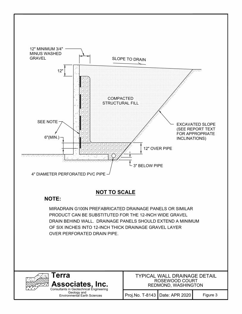
12"
COMPACTED
STRUCTURAL FILL
EXCAVATED SLOPE
(SEE REPORT TEXT
FOR APPROPRIATE
INCLINATIONS)
SLOPE TO DRAIN
12" MINIMUM 3/4"
MINUS WASHED
GRAVEL
3" BELOW PIPE
12" OVER PIPE
4" DIAMETER PERFORATED PVC PIPE
SEE NOTE
6"(MIN.)
NOT TO SCALE
NOTE:
MIRADRAIN G100N PREFABRICATED DRAINAGE PANELS OR SIMILAR
PRODUCT CAN BE SUBSTITUTED FOR THE 12-INCH WIDE GRAVEL
DRAIN BEHIND WALL. DRAINAGE PANELS SHOULD EXTEND A MINIMUM
OF SIX INCHES INTO 12-INCH THICK DRAINAGE GRAVEL LAYER
OVER PERFORATED DRAIN PIPE.
Environmental Earth Sciences
Terra
Associates, Inc.
Consultants in Geotechnical Engineering
Geology and
Figure 3Proj.No. T-8143 Date: APR 2020
TYPICAL WALL DRAINAGE DETAIL ROSEWOOD COURT
REDMOND, WASHINGTON

Project No. T-8143
APPENDIX A FIELD EXPLORATION AND LABORATORY TESTING
Rosewood Court Redmond, Washington
On April 8, 9, and 15, 2019, we completed our site exploration by observing soil and groundwater conditions at 15 test pits and 2 test borings. The test pits were excavated using a trackhoe to a maximum depth of about 13 feet below existing site grades and the test borings drilled to a depth of 101 feet below current site grades. Test pit and test boring locations were determined in the field by measurements from existing site features. The approximate locations of the test pits and the test borings are shown on the attached Exploration Location Plan, Figure 2. The Test Pit and Test Boring Logs are attached as Figures A-2 through A-18.
A geotechnical engineer from our office conducted the field exploration. Our representative classified the soil conditions encountered, maintained a log of each test pit, obtained representative soil samples, and recorded water levels observed during excavation. During drilling, soil samples were obtained in general accordance with ASTM Test Designation D-1586. Using this procedure, a 2-inch (outside diameter) split barrel sampler is driven into the ground 18 inches using a 140-pound hammer free falling a height of 30 inches.chase The number of blows required to drive the sampler 12 inches after an initial 6-inch set is referred to as the Standard Penetration Resistance value or N value. This is an index related to the consistency of cohesive soils and relative density of cohesionless materials. N values obtained for each sampling interval are recorded on the Test Boring Logs, Figures A-17 and A-18. All soil samples were visually classified in accordance with the Unified Soil Classification System (USCS) described on Figure A-1.
Representative soil samples obtained from the test pits and test borings were placed in closed containers and taken to our laboratory for further examination and testing. The moisture content of each sample was measured and is reported on the individual Test Pit and Test Boring Logs. Grain size analyses were performed on selected samples. The results of the analysis are shown on Figures A-19 and A-20.

Environmental Earth Sciences
Terra
Associates, Inc.
Consultants in Geotechnical Engineering
Geology and
MAJOR DIVISIONS
LETTER
SYMBOL
TYPICAL DESCRIPTION
GRAVELS
More than 50%
of coarse fraction
is larger than No.
4 sieve
Clean
Gravels (less
than 5%
fines)
GW
Well-graded gravels, gravel-sand mixtures, little or no fines.
GP
Poorly-graded gravels, gravel-sand mixtures, little or no fines.
Gravels with
fines
GM
Silty gravels, gravel-sand-silt mixtures, non-plastic fines.
GC
Clayey gravels, gravel-sand-clay mixtures, plastic fines.
SANDS
More than 50%
of coarse fraction
is smaller than
No. 4 sieve
Clean Sands
(less than
5% fines)
SW
Well-graded sands, sands with gravel, little or no fines.
SP
Poorly-graded sands, sands with gravel, little or no fines.
Sands with
fines
SM
Silty sands, sand-silt mixtures, non-plastic fines.
SC
Clayey sands, sand-clay mixtures, plastic fines.
SILTS AND CLAYS
Liquid Limit is less than 50%
ML
Inorganic silts, rock flour, clayey silts with slight plasticity.
CL
Inorganic clays of low to medium plasticity. (Lean clay)
OL
Organic silts and organic clays of low plasticity.
SILTS AND CLAYS
Liquid Limit is greater than 50%
MH
Inorganic silts, elastic.
CH
Inorganic clays of high plasticity. (Fat clay)
OH
Organic clays of high plasticity.
HIGHLY ORGANIC SOILS PTPeat.
CO
AR
SE
G
RA
IN
ED
S
OIL
S
Mo
re
th
an
5
0%
m
ate
ria
l la
rg
er
th
an
N
o. 2
00
sie
ve
size
FIN
E G
RA
IN
ED
S
OIL
S
Mo
re
th
an
5
0%
m
ate
ria
l sm
alle
r
th
an
N
o. 2
00
sie
ve
size
DEFINITION OF TERMS AND SYMBOLS
CO
HE
SIO
NL
ES
SC
OH
ES
IV
E
Standard Penetration
Density Resistance in Blows/Foot
Very Loose 0-4
Loose 4-10
Medium Dense 10-30
Dense 30-50
Very Dense >50
Standard Penetration
Consistancy Resistance in Blows/Foot
Very Soft 0-2
Soft 2-4
Medium Stiff 4-8
Stiff 8-16
Very Stiff 16-32
Hard >32
2" OUTSIDE DIAMETER SPILT SPOON SAMPLER
2.4" INSIDE DIAMETER RING SAMPLER OR
SHELBY TUBE SAMPLER
WATER LEVEL (Date)
Tr TORVANE READINGS, tsf
Pp PENETROMETER READING, tsf
DD DRY DENSITY, pounds per cubic foot
LL LIQUID LIMIT, percent
PI PLASTIC INDEX
N STANDARD PENETRATION, blows per foot
Figure A-1Proj.No. T-8143 Date: APR 2020
UNIFIED SOIL CLASSIFICATION SYSTEM ROSEWOOD COURT
REDMOND, WASHINGTON

Sam
ple
No.
Dep
th (
ft)
PROJECT NAME: PROJ. NO: LOGGED BY:
LOCATION:
DATE LOGGED:
APPROX. ELEV:
DEPTH TO CAVING:
FIGURE
DEPTH TO GROUNDWATER:
SURFACE CONDITIONS:
DescriptionConsistency/
Relative Density W (
%)
interpreted as being indicative of other locations at the site.NOTE: This subsurface information pertains only to this test pit location and should not be
0
1
2
3
4
5
6
7
8
9
10
11
12
13
14
15
A-2
T-8143 HM
Redmond, Washington Brush
April 15, 2019
Redmond Subdivision
LOG OF TEST PIT NO. TP-1
N/A
4 Feet N/A
1
2
3
4
Black silty SAND, fine to medium sand, moist, heavy organic inclusions. (SM) (Topsoil)
Brown silty SAND with gravel, fine to medium sand, fine gravel, moist to wet, scattered organics.(SM) (Weathered Till)
Gray SAND with silt and gravel, fine to medium sand, fine gravel, moist to wet. (SP-SM)
Gray silty SAND with gravel, fine to medium sand, fine gravel, moist to wet, trace cobbles.(SM) (Till)
Test pit terminated at approximately 11.5 feet.Minor groundwater seepage observed at approximately 4 feet.
Very Loose
Medium Dense
Dense
30.8
16.8
17.8
18

Sam
ple
No.
Dep
th (
ft)
PROJECT NAME: PROJ. NO: LOGGED BY:
LOCATION:
DATE LOGGED:
APPROX. ELEV:
DEPTH TO CAVING:
FIGURE
DEPTH TO GROUNDWATER:
SURFACE CONDITIONS:
DescriptionConsistency/
Relative Density W (
%)
interpreted as being indicative of other locations at the site.NOTE: This subsurface information pertains only to this test pit location and should not be
0
1
2
3
4
5
6
7
8
9
10
A-3
T-8143 HM
Redmond, Washington Brush
April 15, 2019
Redmond Subdivision
LOG OF TEST PIT NO. TP-2
N/A
N/A N/A
1
2
3
(11 inches of topsoil)Brown silty SAND with gravel, fine to medium sand, fine gravel, moist to wet, scattered tree roots,trace cobbles. (SM) (Weathered Till)
Gray silty SAND with gravel, fine to coarse sand, fine to coarse gravel, moist, trace cobbles.(SM) (Till)
*Boulder observed at 6.5 feet.
Test pit terminated at approximately 9 feet.No groundwater seepage observed.
Medium Dense
Dense to VeryDense
18.8
12.6
10.5

Sam
ple
No.
Dep
th (
ft)
PROJECT NAME: PROJ. NO: LOGGED BY:
LOCATION:
DATE LOGGED:
APPROX. ELEV:
DEPTH TO CAVING:
FIGURE
DEPTH TO GROUNDWATER:
SURFACE CONDITIONS:
DescriptionConsistency/
Relative Density W (
%)
interpreted as being indicative of other locations at the site.NOTE: This subsurface information pertains only to this test pit location and should not be
0
1
2
3
4
5
6
7
8
9
10
11
12
13
14
15
A-4
T-8143 HM
Redmond, Washington Brush
April 15, 2019
Redmond Subdivision
LOG OF TEST PIT NO. TP-3
N/A
N/A N/A
1
2
3
Black silty SAND, fine to medium sand, moist, heavy organic inclusions. (SM) (Topsoil)
Brown silty SAND with gravel, fine to medium sand, fine gravel, moist, scattered organics.(SM) (Weathered Till)
Gray silty SAND with gravel, fine to medium sand, fine to coarse gravel, moist, trace cobbles.(SM) (Till)
Test pit terminated at approximately 10 feet.No groundwater seepage observed.
Very Loose
Medium Dense
Dense to VeryDense
15.5
11
8.4

Sam
ple
No.
Dep
th (
ft)
PROJECT NAME: PROJ. NO: LOGGED BY:
LOCATION:
DATE LOGGED:
APPROX. ELEV:
DEPTH TO CAVING:
FIGURE
DEPTH TO GROUNDWATER:
SURFACE CONDITIONS:
DescriptionConsistency/
Relative Density W (
%)
interpreted as being indicative of other locations at the site.NOTE: This subsurface information pertains only to this test pit location and should not be
0
1
2
3
4
5
6
7
8
9
10
11
12
13
14
15
A-5
T-8143 HM
Redmond, Washington Brush
April 15, 2019
Redmond Subdivision
LOG OF TEST PIT NO. TP-4
N/A
5.5 Feet N/A
1
2
3
Black silty SAND, fine to medium sand, moist, heavy organic inclusions. (SM) (Topsoil)
Tan-brown silty SAND with gravel, fine to medium sand, fine to coarse gravel, moist to wet,scattered rootlets. (SM) (Weathered Till)
Gray silty SAND with gravel, fine to medium sand, fine to coarse gravel, moist, trace cobbles.(SM) (Till)
Test pit terminated at approximately 10.5 feet.Minor groundwater seepage observed at 5.5 feet.
Very Loose
Medium Dense
Dense to VeryDense
16.9
16.6
10.9
Sam
ple
No.
Dep
th (
ft)
PROJECT NAME: PROJ. NO: LOGGED BY:
LOCATION:
DATE LOGGED:
APPROX. ELEV:
DEPTH TO CAVING:
FIGURE
DEPTH TO GROUNDWATER:
SURFACE CONDITIONS:
DescriptionConsistency/
Relative Density W (
%)
interpreted as being indicative of other locations at the site.NOTE: This subsurface information pertains only to this test pit location and should not be
0
1
2
3
4
5
6
7
8
9
10
11
12
13
14
15
A-6
T-8143 HM
Redmond, Washington Brush
April 15, 2019
Redmond Subdivision
LOG OF TEST PIT NO. TP-5
N/A
N/A N/A
1
2
3
4
Black silty SAND, fine to medium sand, moist, heavy organic inclusions. (SM) (Topsoil)
Brown silty SAND with gravel, fine to medium sand, fine gravel, moist to wet, scattered organics.(SM) (Weathered)
Gray SAND with silt and gravel, fine to medium sand, fine gravel, moist to wet, trace cobbles.(SP-SM)
Gray silty SAND with gravel, fine to medium sand, fine to coarse gravel, moist, trace cobbles.(SM) (Till)
Test pit terminated at approximately 12 feet.No groundwater seepage observed.
Very Loose
Medium Dense
Dense
Dense to VeryDense
22.6
16.3
17.6
11.6

Sam
ple
No.
Dep
th (
ft)
PROJECT NAME: PROJ. NO: LOGGED BY:
LOCATION:
DATE LOGGED:
APPROX. ELEV:
DEPTH TO CAVING:
FIGURE
DEPTH TO GROUNDWATER:
SURFACE CONDITIONS:
DescriptionConsistency/
Relative Density W (
%)
interpreted as being indicative of other locations at the site.NOTE: This subsurface information pertains only to this test pit location and should not be
0
1
2
3
4
5
6
7
8
9
10
11
12
13
14
15
A-7
T-8143 HM
Redmond, Washington Brush
April 15, 2019
Redmond Subdivision
LOG OF TEST PIT NO. TP-6
N/A
N/A N/A
1
2
3
Black silty SAND, fine to medium sand, moist, heavy organic inclusions. (SM) (Topsoil)
Fill: Brown silty SAND with gravel, fine to medium sand, fine gravel, moist, scattered organics,wood and plastic debris. (SM)
Tan-brown silty SAND with gravel, fine to medium sand, fine gravel, moist. (SM) (Weathered Till)
Gray silty SAND with gravel, fine to medium sand, fine gravel, moist, trace cobbles. (SM) (Till)
Test pit terminated at approximately 10.5 feet.No groundwater seepage observed.
Very Loose
Loose to MediumDense
Medium Dense
Dense
33.3
11.7
16.1

Sam
ple
No.
Dep
th (
ft)
PROJECT NAME: PROJ. NO: LOGGED BY:
LOCATION:
DATE LOGGED:
APPROX. ELEV:
DEPTH TO CAVING:
FIGURE
DEPTH TO GROUNDWATER:
SURFACE CONDITIONS:
DescriptionConsistency/
Relative Density W (
%)
interpreted as being indicative of other locations at the site.NOTE: This subsurface information pertains only to this test pit location and should not be
0
1
2
3
4
5
6
7
8
9
10
11
12
13
14
15
A-8
T-8143 HM
Redmond, Washington Brush
April 15, 2019
Redmond Subdivision
LOG OF TEST PIT NO. TP-7
N/A
N/A N/A
1
2
3
4
Black silty SAND, fine to medium sand, moist, heavy organic inclusions. (SM) (Topsoil)
Brown silty SAND with gravel, fine to medium sand, fine gravel, moist to wet, scattered organics.(SM) (Weathered Till)
Gray silty SAND with gravel, fine to medium sand, fine to coarse gravel, moist, trace cobbles.(SM) (Till)
Test pit terminated at approximately 11 feet.No groundwater seepage observed.
Very Loose
Medium Dense
Dense to VeryDense
27
18.4
17.9
16.8

Sam
ple
No.
Dep
th (
ft)
PROJECT NAME: PROJ. NO: LOGGED BY:
LOCATION:
DATE LOGGED:
APPROX. ELEV:
DEPTH TO CAVING:
FIGURE
DEPTH TO GROUNDWATER:
SURFACE CONDITIONS:
DescriptionConsistency/
Relative Density W (
%)
interpreted as being indicative of other locations at the site.NOTE: This subsurface information pertains only to this test pit location and should not be
0
1
2
3
4
5
6
7
8
9
10
11
12
13
14
15
A-9
T-8143 HM
Redmond, Washington Brush
April 15, 2019
Redmond Subdivision
LOG OF TEST PIT NO. TP-8
N/A
N/A N/A
1
2
3
Black silty SAND, fine to medium sand, moist, heavy organic inclusions. (SM) (Topsoil)
Tan-brown silty SAND with gravel, fine to medium sand, fine gravel, moist to wet, scatteredorganics. (SM) (Weathered Till)
Gray silty SAND with gravel, fine to medium sand, fine to coarse gravel, moist, trace cobbles.(SM) (Till)
Test pit terminated at approximately 9.5 feet.No groundwater seepage observed.
Very Loose
Medium Dense
Dense to VeryDense
22
10.2
10.8

Sam
ple
No.
Dep
th (
ft)
PROJECT NAME: PROJ. NO: LOGGED BY:
LOCATION:
DATE LOGGED:
APPROX. ELEV:
DEPTH TO CAVING:
FIGURE
DEPTH TO GROUNDWATER:
SURFACE CONDITIONS:
DescriptionConsistency/
Relative Density W (
%)
interpreted as being indicative of other locations at the site.NOTE: This subsurface information pertains only to this test pit location and should not be
0
1
2
3
4
5
6
7
8
9
10
11
12
13
14
15
A-10
T-8143 HM
Redmond, Washington Brush
April 15, 2019
Redmond Subdivision
LOG OF TEST PIT NO. TP-9
N/A
7 Feet N/A
1
2
3
4
Black silty SAND, fine to medium sand, moist, heavy organic inclusions. (SM) (Topsoil)
Brown silty SAND with gravel, fine to medium sand, fine gravel, moist to wet, scattered organics.(SM) (Weathered Till)
Gray silty SAND with gravel, fine to medium sand, fine to coarse gravel, moist, trace cobbles.(SM) (Till)
Test pit terminated at approximately 13 feet.Minor groundwater seepage observed at approximately 7 feet.
Very Loose
Medium Dense
Dense to VeryDense
25.7
15.6
13
11.8

Sam
ple
No.
Dep
th (
ft)
PROJECT NAME: PROJ. NO: LOGGED BY:
LOCATION:
DATE LOGGED:
APPROX. ELEV:
DEPTH TO CAVING:
FIGURE
DEPTH TO GROUNDWATER:
SURFACE CONDITIONS:
DescriptionConsistency/
Relative Density W (
%)
interpreted as being indicative of other locations at the site.NOTE: This subsurface information pertains only to this test pit location and should not be
0
1
2
3
4
5
6
7
8
9
10
11
12
13
14
15
A-11
T-8143 HM
Redmond, Washington Brush
April 15, 2019
Redmond Subdivision
LOG OF TEST PIT NO. TP-10
N/A
5 Feet N/A
1
2
3
Black silty SAND, fine to medium sand, moist, heavy organic inclusions. (SM) (Topsoil)
Brown silty SAND with gravel, fine to medium sand, fine gravel, moist, scattered organics.(SM) (Weathered Till)
*Boulder observed at 3 feet.
Gray silty SAND with gravel, fine to medium sand, fine to coarse gravel, moist, trace cobbles.(SM) (Till)
Test pit terminated at approximately 9.5 feet.Minor groundwater seepage observed at approximately 5 feet.
Very Loose
Medium Dense
Dense to VeryDense
11.6
9.4
9.1

Sam
ple
No.
Dep
th (
ft)
PROJECT NAME: PROJ. NO: LOGGED BY:
LOCATION:
DATE LOGGED:
APPROX. ELEV:
DEPTH TO CAVING:
FIGURE
DEPTH TO GROUNDWATER:
SURFACE CONDITIONS:
DescriptionConsistency/
Relative Density W (
%)
interpreted as being indicative of other locations at the site.NOTE: This subsurface information pertains only to this test pit location and should not be
0
1
2
3
4
5
6
7
8
9
10
A-12
T-8143 HM
Redmond, Washington Brush
April 15, 2019
Redmond Subdivision
LOG OF TEST PIT NO. TP-11
N/A
N/A N/A
1
2
3
Black silty SAND, fine to medium sand, moist, heavy organic inclusions. (SM) (Topsoil)
Tan-brown silty SAND with gravel, fine to medium sand, fine to coarse gravel, moist, trace cobbles.(SM) (Weathered Till)
Gray silty SAND with gravel, fine to medium sand, fine to coarse gravel, moist, trace cobbles.(SM) (Till)
Test pit terminated at approximately 8.5 feet.No groundwater seepage observed.
Very Loose
Medium Denseto Dense
Very Dense
17.6
11.7
11.3

Sam
ple
No.
Dep
th (
ft)
PROJECT NAME: PROJ. NO: LOGGED BY:
LOCATION:
DATE LOGGED:
APPROX. ELEV:
DEPTH TO CAVING:
FIGURE
DEPTH TO GROUNDWATER:
SURFACE CONDITIONS:
DescriptionConsistency/
Relative Density W (
%)
interpreted as being indicative of other locations at the site.NOTE: This subsurface information pertains only to this test pit location and should not be
0
1
2
3
4
5
6
7
8
9
10
11
12
13
14
15
A-13
T-8143 HM
Redmond, Washington Brush
April 15, 2019
Redmond Subdivision
LOG OF TEST PIT NO. TP-12
N/A
4 Feet N/A
1
2
3
Black silty SAND, fine to medium sand, moist, heavy organic inclusions. (SM) (Topsoil)
Brown silty SAND with gravel, fine to medium sand, fine gravel, moist, wet, scattered organics.(SM) (Weathered Till)
Gray silty SAND with gravel, fine to coarse sand, fine gravel, moist, trace cobbles. (SM) (Till)
Test pit terminated at approximately 9.5 feet.Minor groundwater seepage observed at approximately 4 feet.
Very Loose
Medium Dense
Dense
22.8
17.8
10.8

Sam
ple
No.
Dep
th (
ft)
PROJECT NAME: PROJ. NO: LOGGED BY:
LOCATION:
DATE LOGGED:
APPROX. ELEV:
DEPTH TO CAVING:
FIGURE
DEPTH TO GROUNDWATER:
SURFACE CONDITIONS:
DescriptionConsistency/
Relative Density W (
%)
interpreted as being indicative of other locations at the site.NOTE: This subsurface information pertains only to this test pit location and should not be
0
1
2
3
4
5
6
7
8
9
10
11
12
13
14
15
A-14
T-8143 HM
Redmond, Washington Brush
April 15, 2019
Redmond Subdivision
LOG OF TEST PIT NO. TP-13
N/A
5.5 Feet N/A
1
2
3
Black silty SAND, fine to medium sand, moist, heavy organic inclusions. (SM) (Topsoil)
Fill: Brown silty SAND with gravel, fine to medium sand, fine gravel, moist, wood and plastic debris,brick, scattered organics. (SM)
Brown silty SAND with gravel, fine to medium dense, fine gravel, moist. (SM) (Weathered Till)
*Boulder observed at 4.5 feet.
Gray silty SAND with gravel, fine to coarse sand, fine gravel, moist, trace cobbles. (SM) (Till)
Test pit terminated at approximately 9.5 feet.Minor groundwater seepage observed at approximately 5.5 feet.
Very Loose
Loose to MediumDense
Medium Dense
Dense
27.3
19.3
10.2

Sam
ple
No.
Dep
th (
ft)
PROJECT NAME: PROJ. NO: LOGGED BY:
LOCATION:
DATE LOGGED:
APPROX. ELEV:
DEPTH TO CAVING:
FIGURE
DEPTH TO GROUNDWATER:
SURFACE CONDITIONS:
DescriptionConsistency/
Relative Density W (
%)
interpreted as being indicative of other locations at the site.NOTE: This subsurface information pertains only to this test pit location and should not be
0
1
2
3
4
5
6
7
8
9
10
11
12
13
14
15
A-15
T-8143 HM
Redmond, Washington Brush
April 15, 2019
Redmond Subdivision
LOG OF TEST PIT NO. TP-14
N/A
N/A N/A
1
2
3
(6-inch concrete slab)Black silty SAND, fine to medium sand, moist, heavy organic inclusions. (SM) (Topsoil)
Brown silty SAND with gravel, fine to medium sand, fine gravel, moist. (SM) (Weathered Till)
Gray silty SAND with gravel, fine to medium sand, fine gravel, moist, trace cobbles. (SM) (Till)
Test pit terminated at approximately 10 feet.No groundwater seepage observed.
Very Loose
Medium Dense
Dense to VeryDense
20.1
17
11

Sam
ple
No.
Dep
th (
ft)
PROJECT NAME: PROJ. NO: LOGGED BY:
LOCATION:
DATE LOGGED:
APPROX. ELEV:
DEPTH TO CAVING:
FIGURE
DEPTH TO GROUNDWATER:
SURFACE CONDITIONS:
DescriptionConsistency/
Relative Density W (
%)
interpreted as being indicative of other locations at the site.NOTE: This subsurface information pertains only to this test pit location and should not be
0
1
2
3
4
5
6
7
8
9
10
A-16
T-8143 HM
Redmond, Washington Brush
April 15, 2019
Redmond Subdivision
LOG OF TEST PIT NO. TP-15
N/A
4 Feet N/A
1
2
3
Black silty SAND, fine to medium sand, moist, heavy organic inclusions. (SM) (Topsoil)
Brown silty SAND with gravel, fine to medium sand, fine to coarse gravel, moist, trace cobbles.(SM) (Weathered Till)
Gray silty SAND with gravel, fine to medium sand, fine to coarse gravel, moist, trace cobbles.(SM) (Till)
*Boulder observed at 5.5 feet.
Test pit terminated at approximately 9 feet.Minor groundwater seepage observed at approximately 4 feet
Very Loose
Medium Dense
Dense to VeryDense
23.6
15.9
9

Figure No.
Project: Project No:
Logged By:Driller:
Location: Approx. Elev:
Client:
Relative Density
Consistency/Soil Description
SPT (N)
Blows/foot
10 30 50
Date Drilled:
Depth to Groundwater:
Sam
ple
Inte
rval
Dep
th (
ft)
Moi
stur
eC
onte
nt (
%)
pertains only to this boring location and should not be interpeted as being indicative ofNOTE: This borehole log has been prepared for geotechnical purposes. This information
other areas of the site
0
5
10
15
20
25
30
A-17LOG OF BORING NO. B-1
Redmond Subdivision T-8143 April 8, 2019
KRBoreTechD.R. Horton
Redmond, Washington N/A78 Feet
27
71
50/5"
73
100
50/4"
50/5"
Medium Dense
Very Dense
Brown-gray silty SAND with gravel, fine to medium sand, fine gravel,moist. (SM) (Weathered Till)
Brown-gray silty SAND with gravel, fine to medium sand, fine gravel,moist. (SM) (Till)
*At 10 feet increasing gravel content, moderately cemented.
*See Next Page
7.5
9.8
8.3
12.1
11.8
10.8
7.5

Figure No.
Project: Project No:
Logged By:Driller:
Location: Approx. Elev:
Client:
Relative Density
Consistency/Soil Description
SPT (N)
Blows/foot
10 30 50
Date Drilled:
Depth to Groundwater:
Sam
ple
Inte
rval
Dep
th (
ft)
Moi
stur
eC
onte
nt (
%)
pertains only to this boring location and should not be interpeted as being indicative ofNOTE: This borehole log has been prepared for geotechnical purposes. This information
other areas of the site
30
35
40
45
50
55
60
A-17LOG OF BORING NO. B-1
Redmond Subdivision T-8143 April 8, 2019
KRBoreTechD.R. Horton
Redmond, Washington N/A78 Feet
50/4"
50/6"
50/5"
50/6"
50/5"
50/6"
Very Dense
Brown-gray silty SAND with gravel, fine to medium sand, fine gravel,moist. (SM) (Till)
*At 35 feet, moist to wet.
*At 40 feet, decreasing gravel content.
Gray-brown SAND with gravel, fine to medium sand, fine gravel.(SP)
Gray-brown silty SAND with gravel, fine to medium sand, moist.(SM) (Till)
Brown-gray SAND with gravel, fine to medium sand, fine gravel,moist. (SP) (Advance Outwash)
*See Next Page
12.1
10.3
3.9
11.8
5.2
2.9

Figure No.
Project: Project No:
Logged By:Driller:
Location: Approx. Elev:
Client:
Relative Density
Consistency/Soil Description
SPT (N)
Blows/foot
10 30 50
Date Drilled:
Depth to Groundwater:
Sam
ple
Inte
rval
Dep
th (
ft)
Moi
stur
eC
onte
nt (
%)
pertains only to this boring location and should not be interpeted as being indicative ofNOTE: This borehole log has been prepared for geotechnical purposes. This information
other areas of the site
60
65
70
75
80
85
90
A-17LOG OF BORING NO. B-1
Redmond Subdivision T-8143 April 8, 2019
KRBoreTechD.R. Horton
Redmond, Washington N/A78 Feet
50/4"
50/6"
50/4"
50/5"
50/5"
50/6"
Hard
Very Dense
Brown-gray SAND with gravel, fine to medium sand, fine gravel,moist. (SP) (Advance Outwash)
Brown silty SAND, fine sand, moist. (SM) (Advanced Outwash)
Brown-gray SAND, fine to medium sand, moist.(SP) (Advance Outwash)
Gray-brown silty SAND to SILT with gravel, fine sand, fine gravel,moist to wet. (SM/ML)
*At 80 feet observed wet seam.
Brown-gray mottled SILT with sand, fine sand, non-plastic, wet. (ML)
*See Next Page
14.2
5.5
15.5
20.7
23.8
26.126.1

Figure No.
Project: Project No:
Logged By:Driller:
Location: Approx. Elev:
Client:
Relative Density
Consistency/Soil Description
SPT (N)
Blows/foot
10 30 50
Date Drilled:
Depth to Groundwater:
Sam
ple
Inte
rval
Dep
th (
ft)
Moi
stur
eC
onte
nt (
%)
pertains only to this boring location and should not be interpeted as being indicative ofNOTE: This borehole log has been prepared for geotechnical purposes. This information
other areas of the site
90
95
100
105
110
115
120
A-17LOG OF BORING NO. B-1
Redmond Subdivision T-8143 April 8, 2019
KRBoreTechD.R. Horton
Redmond, Washington N/A78 Feet
128
50/4"
Very Dense
Hard
HardBrown-gray mottled SILT with SAND, fine sand, non-plastic, wet.(ML)
Brown-gray SAND, medium sand, moist to wet. (SP)
Brown-gray SILT with sand, fine sand, non-plastic, wet. (ML)
Boring terminated at approximately 101 feet.Groundwater observed at 78 feet.
21.1
26.5

Figure No.
Project: Project No:
Logged By:Driller:
Location: Approx. Elev:
Client:
Relative Density
Consistency/Soil Description
SPT (N)
Blows/foot
10 30 50
Date Drilled:
Depth to Groundwater:
Sam
ple
Inte
rval
Dep
th (
ft)
Moi
stur
eC
onte
nt (
%)
pertains only to this boring location and should not be interpeted as being indicative ofNOTE: This borehole log has been prepared for geotechnical purposes. This information
other areas of the site
0
5
10
15
20
25
30
A-18LOG OF BORING NO. B-2
Redmond Subdivision T-8143 April 9, 2019
KRBoreTechD.R. Horton
Redmond, Washington N/A88 Feet
65
55
50/5"
50/6"
50/4"
50/4"
50/5"
Very Dense
Medium Dense
Very Dense
Dark brown silty SAND to SILT, fine sand, moist, roots and woodpieces. (SM/ML)
Brown-gray silty SAND with gravel, fine to medium sand, fine gravel,moist to wet, mottled. (SM) (Weathered Till)
Brown to brown-gray silty SAND with gravel, fine to medium sand,fine gravel, moist, mottled. (SM) (Till)
*Soil is not mottled.
Gray-brown SAND with silt and gravel, fine to medium sand, moist towet. (SP-SM) *See Next Page
37.1
9.2
10.1
7.5
10.8
9.3
11.1

Figure No.
Project: Project No:
Logged By:Driller:
Location: Approx. Elev:
Client:
Relative Density
Consistency/Soil Description
SPT (N)
Blows/foot
10 30 50
Date Drilled:
Depth to Groundwater:
Sam
ple
Inte
rval
Dep
th (
ft)
Moi
stur
eC
onte
nt (
%)
pertains only to this boring location and should not be interpeted as being indicative ofNOTE: This borehole log has been prepared for geotechnical purposes. This information
other areas of the site
30
35
40
45
50
55
60
A-18LOG OF BORING NO. B-2
Redmond Subdivision T-8143 April 9, 2019
KRBoreTechD.R. Horton
Redmond, Washington N/A88 Feet
50/6"
50/5"
50/6"
50/5"
50/4"
50/3"
Very Dense
Gray-brown SAND with silt and gravel, fine to medium sand, moist towet. (SP-SM)
Gray-brown silty SAND with gravel, fine to medium sand, fine gravel,moist. (SM) (Till)
Gray-brown SAND, fine to medium sand, moist, trace gravel.(SP) (Advance Outwash)
Gray to brown silty SAND, fine sand, moist.(SM) (Advance Outwash)
Brown-gray SAND with gravel, fine to medium sand, fine gravel,moist. (SP) (Advance Outwash)
Brown-gray silty SAND with gravel, fine sand, fine gravel, moist.(SM) (Advance Outwash) *See Next Page
8.9
9.8
8
16.3
6.7
11.2

Figure No.
Project: Project No:
Logged By:Driller:
Location: Approx. Elev:
Client:
Relative Density
Consistency/Soil Description
SPT (N)
Blows/foot
10 30 50
Date Drilled:
Depth to Groundwater:
Sam
ple
Inte
rval
Dep
th (
ft)
Moi
stur
eC
onte
nt (
%)
pertains only to this boring location and should not be interpeted as being indicative ofNOTE: This borehole log has been prepared for geotechnical purposes. This information
other areas of the site
60
65
70
75
80
85
90
A-18LOG OF BORING NO. B-2
Redmond Subdivision T-8143 April 9, 2019
KRBoreTechD.R. Horton
Redmond, Washington N/A88 Feet
50/4"
50/5"
50/4"
50/5"
50/4"
50/4"
Hard
Very Dense
Very Dense
Brown-gray silty SAND with gravel, fine sand, fine gravel, moist.(SM) (Advance Outwash)
Brown to gray SAND with silt, fine to medium sand, moist. (SP-SM)(Advance Outwash)
Brown to gray SAND with gravel, fine to medium sand, fine gravel,moist. (SP) (Advance Outwash)
Brown SILT with sand and gravel, fine sand, fine gravel, non-plastic,moist. (ML)
*At 85 feet observed some gravel.
Gray-brown silty SAND, fine to medium sand, moist, mottled. (SM)*See Next Page
10.5
5.5
9.2
15.6
21.9
21.921.9

Figure No.
Project: Project No:
Logged By:Driller:
Location: Approx. Elev:
Client:
Relative Density
Consistency/Soil Description
SPT (N)
Blows/foot
10 30 50
Date Drilled:
Depth to Groundwater:
Sam
ple
Inte
rval
Dep
th (
ft)
Moi
stur
eC
onte
nt (
%)
pertains only to this boring location and should not be interpeted as being indicative ofNOTE: This borehole log has been prepared for geotechnical purposes. This information
other areas of the site
90
95
100
105
110
115
120
A-18LOG OF BORING NO. B-2
Redmond Subdivision T-8143 April 9, 2019
KRBoreTechD.R. Horton
Redmond, Washington N/A88 Feet
50/5"
50/4"
Very Dense
Gray-brown silty SAND, fine to medium sand, moist, mottled. (SM)
Brown-gray SAND with silt and gravel, fine to coarse sand, finegravel, wet. (SP-SM)
Brown-gray SAND, medium sand, wet, trace silt. (SP)
Boring terminated at 101 feet.Groundwater observed at 88 feet.
16.2
21.3


