rosette tracker: an open source image analysis … tracker: an open source image analysis tool for...
TRANSCRIPT

Breakthrough Technologies
Rosette Tracker: An Open Source Image Analysis Tool forAutomatic Quantification of Genotype Effects1[C][W]
Jonas De Vylder2, Filip Vandenbussche2*, Yuming Hu, Wilfried Philips, and Dominique Van Der Straeten
Department of Telecommunications and Information Processing (J.D.V., W.P.) and Department of Physiology(F.V., Y.H., D.V.D.S.), Ghent University, 9000 Ghent, Belgium
Image analysis of Arabidopsis (Arabidopsis thaliana) rosettes is an important nondestructive method for studying plant growth.Some work on automatic rosette measurement using image analysis has been proposed in the past but is generally restricted tobe used only in combination with specific high-throughput monitoring systems. We introduce Rosette Tracker, a new opensource image analysis tool for evaluation of plant-shoot phenotypes. This tool is not constrained by one specific monitoringsystem, can be adapted to different low-budget imaging setups, and requires minimal user input. In contrast with previouslydescribed monitoring tools, Rosette Tracker allows us to simultaneously quantify plant growth, photosynthesis, and leaftemperature-related parameters through the analysis of visual, chlorophyll fluorescence, and/or thermal infrared time-lapsesequences. Freely available, Rosette Tracker facilitates the rapid understanding of Arabidopsis genotype effects.
Integration of tools for simultaneous measurementof plant growth and physiological parameters is apromising way to rapidly screen for specific traits.Remote analysis with minimal handling is essential toavoid growth disturbance. For instance, fluorescenceimaging can provide information on chlorophyll con-tent without the need for pigment extraction, and atthe same time, can be used for size estimations ofgreen plants (Jansen et al., 2009). Also, thermal imagescan be used to evaluate relative transpiration differ-ences without having to measure stomatal conduc-tance.
Analysis of plant size or growth is frequently per-formed by destructive techniques that involve theharvesting of whole plants or plant parts at regulartime points. This often requires extensive growth roomor greenhouse space. In recent years, a number ofmethods for systematically tracking plant growth havebeen developed. For growth analysis of the primaryroot or hypocotyl, Root Trace (French et al., 2009) andHypoTrace (Wang et al., 2009) were developed primar-ily for the Arabidopsis (Arabidopsis thaliana) community.
For analysis of rosette growth, a number of tools havebeen developed (Leister et al., 1999; Jansen et al., 2009;Arvidsson et al., 2011). However, the threshold forimplementation is high because the software is tunedfor specific hardware, restricting its accessibility forsmaller labs. Hardware for large-scale screening isusually based on cameras steered into position with arobot (Walter et al., 2007; Jansen et al., 2009; Arvidssonet al., 2011). Therefore, because many labs do not havethe means to invest in such a system, phenotypic anal-ysis of plant growth is still frequently done manually.Plants are either weighed (destructive), scanned (de-structive), or photographed, followed by manual anal-ysis using image annotation software (nondestructive).These methods are time consuming and call for low-budget, user-friendly alternatives.
Several computer vision-based methods have beenproposed to measure and analyze leaf growth in a non-destructive way. We summarize some of these methodsbelow:
“Semiautomatic image analysis” (Jaffe et al., 1985;Guyer et al., 1986; Leister et al., 1999) has been pro-posed to automatically analyze plant growth. Thismethod requires the user to select either a set of train-ing pixels or to manually tweak an intensity thresholdto get robust measurements. The methods are ableto detect plant rosettes on a clear background, butare hampered by a nonuniform background, e.g. soil(Guyer et al., 1986). This restriction can be solved byilluminating the plants with IR (infrared) light.
“Motion-based methods” (Barron and Liptay, 1994;Barron and Liptay, 1997; Schmundt et al., 1998;Aboelela et al., 2005) exploit information from mul-tiple time frames. These methods show accurate re-sults for high quality images of isolated leaves, butare of course restricted to time-lapse sequences. A
1 This work was supported by funds from the Institute for thePromotion of Innovation by Science and Technology in Flanders (toJ.D.V.). D.V.D.S. and F.V. gratefully acknowledge financial supportfrom the Research Foundation – Flanders (G.0298.09, B/12637/01)and Ghent University. F.V. is a postdoctoral researcher of the Re-search Foundation – Flanders.
2 These authors contributed equally to the article.* Corresponding author; e-mail [email protected] author responsible for distribution of materials integral to the
findings presented in this article in accordance with the policy de-scribed in the Instructions for Authors (www.plantphysiol.org) is: Jo-nas De Vylder ([email protected]).
[C] Some figures in this article are displayed in color online but inblack and white in the print edition.
[W] The online version of this article contains Web-only data.www.plantphysiol.org/cgi/doi/10.1104/pp.112.202762
Plant Physiology�, November 2012, Vol. 160, pp. 1149–1159, www.plantphysiol.org � 2012 American Society of Plant Biologists. All Rights Reserved. 1149 www.plantphysiol.orgon July 3, 2018 - Published by Downloaded from
Copyright © 2012 American Society of Plant Biologists. All rights reserved.

major drawback of these “optical flow” approachesis that they have difficulties with regions, which arepartially occluded during a specific time frame.
“Vegetation segmentation” (Shimizu and Heins, 1995;Onyango and Marchant, 2001, 2003; Clément andVigouroux, 2003) represents a group of algorithmsspecifically developed for crop segmentation, i.e. au-tomatically delineating a crop from the soil in animage. These methods only require a visual (VIS)image of a plant in its natural growing environment.Thus, these tools can be used to measure plant growthover time. The vegetation segmentation methods areinvariant to light conditions and independent of thecamera system and crop size. Unfortunately, theyrely on the assumption that the images are bimodal,i.e. the images consist of two types of pixels: pixelsbelonging to a plant or pixels corresponding to soil.The methods will fail if the image contains othertypes of pixels, e.g. corresponding to a tray, moss,cloth, etc. Although these methods are interesting forspecific applications, they are too restrictive for a ge-neric growth analysis system. Moreover, none ofthese methods have an implementation publiclyavailable.
“Growscreen, Growscreen Fluoro, and Lemnagrid”(Walter et al., 2007, 2009; Arvidsson et al., 2011) com-bines image analysis with specific plant monitoringsystems, e.g. the imaging-pulse amplitude-modulatedfluorometer or the ScanalyzerHTS from Lemnatec. Allthree systems provide a wide range of measurementssuch as area, relative growth rate, and compactness.With Growscreen Fluoro, it is also possible to analyzechlorophyll fluorescence images. The downside ofthese frameworks is that they only work in combina-tion with specific monitoring systems. A change oftray, camera, focus, lighting conditions, etc. needs acomplete resetting of parameters, e.g. thresholds usedfor the segmentation of rosettes in the work ofArvidsson et al. (2011) are hard-coded, i.e. they arenot dynamically calculated, instead they have to bemanually set, which is tedious and error-prone be-cause there are no guidelines on how to set specificparameters. Another important disadvantage is thatneither Growscreen, Growscreen Fluoro, nor Lemna-grid is publicly available.
“Montpellier RIO Imaging Cell Image Analyzer”(Baecker, 2007) is a general purpose image analysisImageJ plug-in. It is controlled by a visual scriptingsystem, which is easier to use than regular scripting orprogramming languages, but less user-friendly than aspecialized program with a graphical user interface.However, it is only able to analyze images with asingle rosette in a VIS image, which is obviously agreat disadvantage when large numbers of plantsare to be analyzed without an automated/robotized
image capturing. MRI Cell Image Analyzer can mea-sure the rosette area over time. All parameters aretrained for a specific dataset and should be adjustedfor time-lapse sequences capturedwith a different cam-era system, or with different lighting conditions. Thesystem is open source, and thus can be adapted tothe needs of the user. Both ImageJ and the plug-inare freely available.
“Virtual Leaf” (Merks et al., 2011) is a cell-based com-puter modeling framework for plant tissue morpho-genesis, providing a means to analyze the functionof developmental genes in the context of the bio-physics of growth and patterning. This frameworkbuilds a model by alternating between making ex-perimental observations and refining the model. Thenecessary processing of experiments into quantita-tive observations, however, is lacking in this work.
“Leaf GUI (for graphical user interface) and Limani”(Dhondt et al., 2012; Price et al., 2011) both providea framework for extensive analysis of leaf vein andareole measurements. This image analysis frameworkrequires a high-resolution, high-magnification imageof an isolated, cleared leaf. Thus, this method is inva-sive and does not allow the measuring of the same leafover time. The framework provides a detailed analysisof the fine structures of a leaf but does not give anyinformation about the global leaf or plant growth.
This list is not exhaustive. For a more in-depthoverview of image analysis algorithms, we refer toShamir et al. (2010) and Russ (2011).
With the image analysis software proposed in thispaper, we attempt to combine the strong points of theprevious methods, while resolving major drawbacks.The software tool is able to detect multiple rosettes inan image without assuming bimodal images, i.e. theimages can contain parts that are neither soil nor plants,and it does not require the use of a specific monitoringsystem with fixed lighting conditions, trays, resolution,etc. Specific parameters (e.g. the scale or number ofplants in the field of view) might have to be tuned tocope with time-lapse sequences captured with differentsystems, but these parameters are straightforward andcan easily be adjusted with a few mouse clicks usinga simple graphical user interface. The software toolprovides a wide range of rosette parameter mea-surements, i.e. area, compactness, average intensity,maximum diameter, stockiness, and relative growthrate. Apart from analyzing regular color images (VISimages) and/or chlorophyll fluorescence images, theproposed software tool is also able to measure av-erage rosette intensity in thermal IR images. To thebest of our knowledge, this is the first image analysistool proposed in literature offering all of these fea-tures.
Although several image analysis tools have beenproposed in the past, a robust measurement tool
1150 Plant Physiol. Vol. 160, 2012
De Vylder et al.
www.plantphysiol.orgon July 3, 2018 - Published by Downloaded from Copyright © 2012 American Society of Plant Biologists. All rights reserved.
independent of the monitoring system has not beenreported yet. We have developed such a freeware toolto analyze time-lapse sequences of Arabidopsis ro-settes. In this work, we elaborate on the most impor-tant components of the proposed tool, called RosetteTracker. The first part of the next section will explainhow rosettes are detected in different image modalities.This will provide some technical insight in how RosetteTracker works. Although this technical knowledge isnot necessary to use the software tool, it helps to obtaina view on how the tool functions and to identify thecause of occasional failure. Next, practical issues, suchas which measurements the tool can handle and whatthe requirements are for good time-lapse sequences,will be discussed. Finally, as an example, two plant-growth experiments are analyzed using Rosette Trackerto illustrate its versatility and usefulness.
RESULTS AND DISCUSSION
In the following section, we elaborate on the five dif-ferent components of our image analysis system. Thesekey components consist of (1) calibration of the system,(2) segmentation methods for VIS and chlorophyll fluo-rescence images, (3) rosette detection, (4) registration ofVIS images with IR images, and (5) the set of measure-ments provided for plant growth analysis. Our proposedimage analysis tool, Rosette Tracker, is implemented inthe programming language Java 1.6.2 and can be used asa plug-in for ImageJ. The combination with ImageJ al-lows us to extend the proposed analysis tools with extrafunctionality and measurements available in ImageJ(Abràmoff et al., 2004). Both a compiled plug-in and thesource code are freely available (http://telin.ugent.be/~jdvylder/RosetteTracker/).
Calibration
The conversion of pixels to physical measurementunits, such as millimeters, is necessary to analyze mea-surements like rosette diameter or area. Rosette Trackerhas two main options to calculate the actual scale inmillimeters. The first option assumes that the actualscale is known and allows the user to enter the ratio ofpixels to millimeters in a textbox. If the actual scale isnot known in advance, as is often the case, RosetteTracker provides an easy-to-use graphical tool to set thescale. The user can click on two points in the imagebetween which the real distance is known, for examplethe two corners of a tray. Alternatively, the user cancapture an image that includes a ruler. Based on thedistance in the image (in pixels) and the distance in re-ality (in millimeters), the software tool can approximatethe resolution. To get a good estimation, however, it isimportant that both control points and all rosettes lienearly in the same focal plane, such that they are ap-proximately at the same distance from the camera.
If the user does not set a scale, all distance and areameasurements will be expressed in pixels. Althoughthis does not result in absolute measurements, it allows
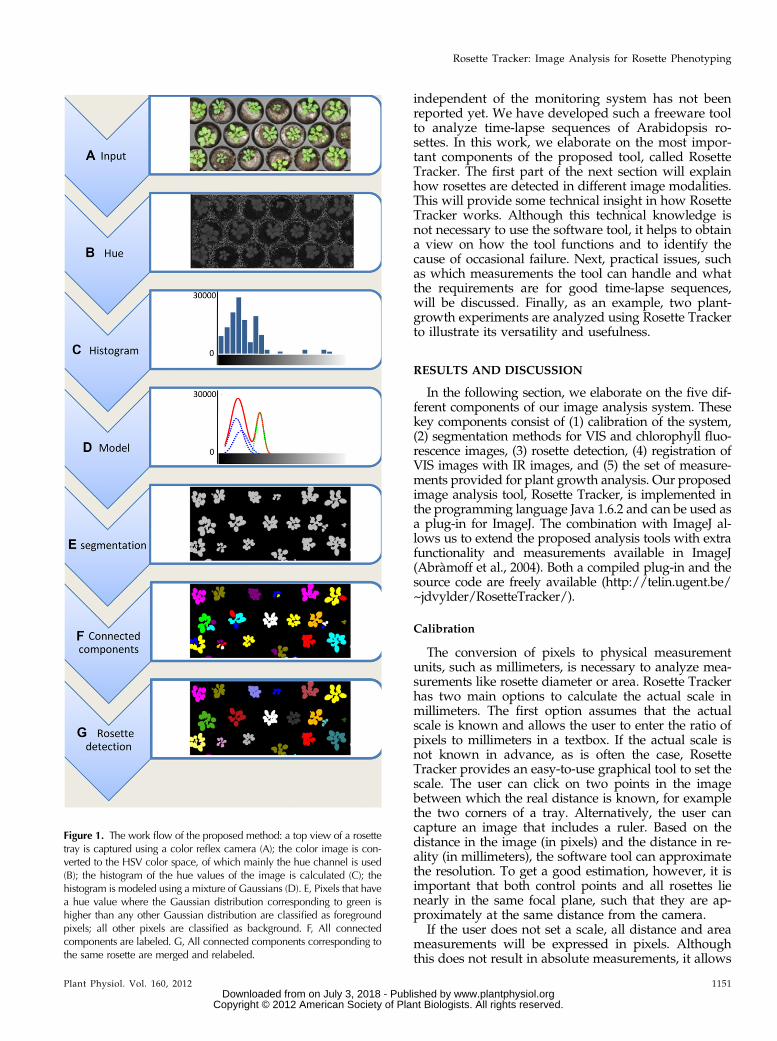
Figure 1. The work flow of the proposed method: a top view of a rosettetray is captured using a color reflex camera (A); the color image is con-verted to the HSV color space, of which mainly the hue channel is used(B); the histogram of the hue values of the image is calculated (C); thehistogram is modeled using a mixture of Gaussians (D). E, Pixels that havea hue value where the Gaussian distribution corresponding to green ishigher than any other Gaussian distribution are classified as foregroundpixels; all other pixels are classified as background. F, All connectedcomponents are labeled. G, All connected components corresponding tothe same rosette are merged and relabeled.
Plant Physiol. Vol. 160, 2012 1151
Rosette Tracker: Image Analysis for Rosette Phenotyping
www.plantphysiol.orgon July 3, 2018 - Published by Downloaded from Copyright © 2012 American Society of Plant Biologists. All rights reserved.
for relative comparison of plants, provided that they aremonitored with the same imaging system.
Segmentation of VIS Images
Color is probably one of the most distinct featuresfor the detection of rosettes in VIS images (Clémentand Vigouroux, 2003; Walter et al., 2007; Arvidssonet al., 2011). Many imaging systems represent colorusing three components: red, green, and blue (RGB).All possible colors that such a system can represent canbe organized as a three-dimensional (3-D) cube. Manyimage analysis tools try to find a region in this RGBcube that corresponds to the green of rosettes in animage. This is not always an easy task because thisregion can have any shape and might vary betweendifferent monitoring systems. A different approach isto first transform the RGB cube to a different repre-sentation that is more intuitive for image analysis andprocessing. An interesting color transformation reor-ders the RGB cube into the HSV (for hue, saturation,and value) cylinder (Agoston, 2005; Walter et al., 2007;Supplemental Fig. S1, A and B). In this cylinder, coloris represented by the three measurements in the name.Hue represents color tone, while saturation corre-sponds to the colors’ distance from white and value tothe luminosity (Supplemental Fig. S1). It is importantto note that the hue value is sufficiently discriminativeto define pixels corresponding to chlorophyll (fromleaf, algae, or moss), whereas the other two parame-ters, saturation and value, are less important. Thus,finding a color region corresponding to the green ofplants is now reduced to finding an interval in onedimension, i.e. the hue dimension, instead of findingan arbitrary shape in three dimensions. An example ofthe hue channel of a color image is shown in Figure 1,A and B. Note that all pixels corresponding to rosettesshow similar hue values. A detailed description anddefinition of different color space, such as RGB andHSV, has been reported previously (Agoston, 2005).
Instead of defining fixed thresholds on a colorcomponent, such as is done in Leister et al., (1999) andArvidsson et al. (2011), a more dynamic approach isnecessary for a software tool that is not coupled withany specific monitoring system. To dynamically detectplants, Clément and Vigouroux (2003) proposed thedetection of peaks in a histogram of color components.Whereas their method works in RGB space and con-strains the image to include only soil or plants, we usethe same concept but omit these constraints. First, thehistogram of the hue values of the image is calculated(Fig. 1C). The peaks or modes in this histogram gen-erally correspond to specific object types in the image,e.g. rosettes will correspond with a peak near the huevalues corresponding with green, whereas soil, trays,labels, etc., will result in different peaks. To detectthese peaks we model the histogram, h(.), with amixture of Gaussians, i.e. we approximate the histo-gram as a weighted sum of Gaussian probabilitydensity functions (Fig. 1D):
hð:Þ� ∑m
i¼1aiNðmi;si
2Þ ð1Þ
where ai represents a weighting parameter and N(mi,si2)
stands for a Gaussian probability density function withmean mi and variance si
2. An example of a descriptionusing a mixture of Gaussians can be seen in Figure 1D,where the hue histogram is approximated by the redcurve. This red curve is the sum of a set of Gaussiandistributions, shown by the green and blue dashed lines.The optimal parameters, i.e. weights, means, and vari-ances that result in the best approximation of thehistogram, can be calculated using expectation maxi-mization optimization (Bilmes, 1997). The expectationmaximization method is an iterative optimization tech-nique that alternates between two steps: an expectationstep, where the expectation of the logarithm of thelikelihood (log-likelihood) of Equation 1 is evaluatedusing the current estimates for the parameters, and amaximization step, where the parameters are optimizedto maximize the expected log-likelihood found in thefirst step. For the exact equations used in each step, werefer to Bilmes (1997).
Each Gaussian probability density function generallycorresponds with the physical appearance of differentobjects, e.g. a Gaussian probability density function forplant pixels, a Gaussian probability density functioncorresponding with tray pixels, etc. Although there canbe numerous objects, and thus Gaussians, only thedistinction between plant and other pixels is relevant.The Gaussian probability density function correspond-ing with rosette pixels is defined as the Gaussian whosemean, mj, is closest to the expected green hue (the greendashed line in Figure 1D). This expected green hue hasa default value of 60 but can easily be changed in thesoftware tool by clicking on a plant pixel. The hue valueof this selected pixel will then be considered as the ex-pected green hue. Given the mixture of Gaussians, eachpixel can be classified based on its hue value; if theprobability that the hue value belongs to a rosette ishigher than the probability that it belongs to a differentclass, and hence a different Gaussian, the pixel is clas-sified as a rosette pixel. In all other cases, the pixel isdiscarded as background.
Note that the expectation maximization algorithm isable to find the optimal parameters for the Gaussianmixture model for a fixed number of Gaussian prob-ability density functions. Predefining this number isnot an easy task because it limits the possible setups;two Gaussians only allow plant and soil pixels wherethe soil is more or less homogenous (Onyango andMarchant, 2003). To avoid predefining, Rosette Trackerstarts the segmentation method using two Gaussianprobability distribution functions and iteratively in-creases the number of Gaussians until correct segmen-tation is achieved. A segmentation result is consideredcorrect if a Gaussian is found with a mean sufficientlyclose to the expected green hue. If the absolute differ-ence between the expected hue and the mean of each
1152 Plant Physiol. Vol. 160, 2012
De Vylder et al.
www.plantphysiol.orgon July 3, 2018 - Published by Downloaded from Copyright © 2012 American Society of Plant Biologists. All rights reserved.
Gaussian is higher than a specific threshold, the num-ber of Gaussians is increased. This threshold is set to 10,assuming that the hue values of the image range from0° to 360°. Note that the hue values have a cyclic nature,i.e. a hue of 0° is equal to a hue of 360° (SupplementalFig. S1B). This wraparound, however, does not causeproblems because a hue equal to 0° corresponds to red(light with a wavelength of approximately 650 nm),which rarely occurs in images of vegetative planttissues.The method proposed above detects all green pixels;
however, this does not exclude green pixels that do notbelong to a rosette, e.g. pixels corresponding to mossor algae growing on the surface of the plant substrate.These pixels have the same hue as rosettes but aregenerally darker than rosettes. Therefore, we can ex-clude them by applying our proposed segmentationalgorithm not only in the hue channel but also in thevalue channel. A true rosette pixel is considered to be apixel that is detected as a rosette pixel both by thesegmentation of the hue and the saturation channels.
Segmentation of Chlorophyll Fluorescence Images
Although the previous segmentation method wasdeveloped for the analysis of VIS images, it can easilybe adapted to work for chlorophyll fluorescence imagesas well. Because these are grayscale images instead ofcolor images, the method is simplified in the followingway. Instead of working in the HSV color space, ahistogram is directly calculated for the chlorophyll fluo-rescence intensities. Subsequently, this histogram ismodeled using a mixture of Gaussians in the same wayas for VIS images, i.e. by iteratively increasing thenumber of Gaussians. However, the criteria to ceaseiteration are different because there is no default ex-pected chlorophyll fluorescence intensity as is the casefor a green hue. Therefore, Rosette Tracker estimatesthe expected intensity for each image independently,using the following steps:
1. Calculate a rough initial segmentation. This seg-mentation will only be used to calculate an estimateof the expected intensity, and is thus less sensitiveto small errors in the segmentation as long as theoverall statistics of the detected foreground resem-ble the real statistics. Such an initial segmentationcan be calculated using different algorithms such as:a. Supervisedpixel classificationmethods (Cristianini
and Shawe-Taylor, 2000; Rabunal and Dorado,2006), which have shown good results but re-quire large amounts of training data. This train-ing is in contrast to the goal of Rosette Tracker,which attempts to be a dynamic analysis systemwith minimal user input.
b. Pixel Clustering-based methods (Lloyd, 1982;Ester et al., 1996; Hall et al., 2009) represent anothergroup of generic intensity-based segmentation
methods. These methods have been efficientlyused for the segmentation of biological objectsbut are strongly dependent on initialization, i.e.an initial estimate of the location of clusters.
c. Threshold methods separate foreground frombackground by comparing pixel intensitieswith a threshold. If the intensity is higher thanthe threshold, the pixel is classified as foreground,otherwise as background. Rosette Tracker usesa threshold-based method because it does not re-quire training or initialization. The threshold usedby Rosette Tracker is calculated using the Auto-Threshold function provided in ImageJ. Thismethod is based on Ridler iterative thresholding(Ridler and Calvard, 1978), where a threshold isiteratively established using the average of theforeground and background class means. For amore detailed description on automatic thresholdmethods, we refer to Otsu (1979), Abràmoff et al.(2004), and Sezgin and Sankur (2004).
2. Calculate the mean intensity of all plant pixels, i.e.all pixels above the threshold.
3. Use this mean as expected chlorophyll fluorescenceintensity.
It is important to note that the expected intensitywill depend on the quality of the segmentation methodin Step 1. Tests showed that the proposed initializationmethod resulted in a good approximation of the ex-pected intensity. If this automatic initialization wouldfail, however, it is also possible to predefine the ex-pected intensity in a similar way as for VIS images, i.e.by clicking a well-chosen pixel in the chlorophyll flu-orescence image.
Rosette Detection
The proposed segmentation method only classifiespixels as corresponding with a rosette pixel or belongingto the background. However, it does not detect to whichrosette a pixel belongs. In several high-throughput sys-tems, this is achieved using prior knowledge about theplant’s location and the pot in which the rosette isgrown (Walter et al., 2007; Arvidsson et al., 2011). Thisknowledge has to be reprogrammed for each differentsetup, e.g. for different trays, different locations of pots,etc. Rosette Tracker proposes a method without thisprior knowledge, thus allowing a dynamic setup whilerequiring a minimal user input.
The output of the segmentation algorithm is repre-sented as a binary image where pixels correspondingto plants are represented by 1, and all other pixels havevalue 0 (Fig. 1E). Using a connected-component algo-rithm, this binary image can be transformed to agrayscale image where all foreground pixels, whichare connected to each other, bear the same label (ide-ally corresponding to a single rosette) whereas pixelsthat are not connected bear a different label. Two
Plant Physiol. Vol. 160, 2012 1153
Rosette Tracker: Image Analysis for Rosette Phenotyping
www.plantphysiol.orgon July 3, 2018 - Published by Downloaded from Copyright © 2012 American Society of Plant Biologists. All rights reserved.

pixels are considered to be connected whenever a pathof consecutive neighboring foreground pixels existsbetween them (Fig. 1F).
Because of shadows, it might be that a single rosetteis not recognized as such, but corresponds to multipleconnected components, each with different labels. Toovercome this, components are merged, i.e. relabeleduntil a predefined number of components remain. Thenumber of final components corresponds to the num-ber of plants visible in the image, which the user has toenter in the settings of Rosette Tracker. This relabelingis done using a clustering approach. Although severalclustering techniques will show good results (Lloyd,1982; Ester et al.; 1996; Hall et al., 2009), we propose anearest-neighbor approach for its simplicity and effi-ciency. The connected components are relabeled byiteratively applying the following steps:
1. Calculate the centroid for each connected compo-nent.
2. Calculate the distance between all centroids.3. Merge the two components that are closest to each
other.
An example of this relabeling is shown in Figure 1G.It is important that rosettes do not touch each other inthe image because this would result in one connectedcomponent corresponding to two rosettes. For a hands-on comparison of different clustering techniques, werefer to the WEKA Data Mining Software (Hall et al.,2009).
To aid the user, Rosette Tracker relabels all rosettessuch that they are ordered row by row. Vertical rowsare automatically detected in the image, based on priorinput of the number of rows. This is done usingnearest-neighbor clustering, i.e. the same clusteringmethod used for the relabeling of connected compo-nents in the rosette detection algorithm. The distancebetween rosettes, i.e. the basis for clustering rosettesinto vertical rows, is defined as the absolute differencein y coordinates of the centroid of each rosette.
Analyzing Thermal IR Images
Although the proposed segmentation method isrelatively generic, e.g. it works on color and grayscaleimages without major modifications, it will not workfor all possible image modalities. Near-IR imagesgenerally have too low of a contrast and are too noisyto obtain proper segmentation results. Instead, RosetteTracker uses the segmentation result from a VIS orchlorophyll fluorescence image to measure intensity ina thermal IR image, i.e. the segmentation result isprojected as a mask onto the IR image.
To ensure proper correspondence between the seg-ment and the rosette in the IR image, the segment firsthas to be warped, i.e. deformed in a specific way. Thishas to be done to cope with difference in scale, focus,small differences in location of the VIS and IR camera,
lens distortion, etc. This is often done based on a set oflandmarks, i.e. corresponding points that are anno-tated by the user in both VIS and IR images (Bookstein,1989; Beatson et al., 2007). The result of this warpingstrongly depends on the accuracy with which a usercan detect corresponding points in IR and VIS images.Low contrast and blur, however, hamper the accuratedetection of landmarks in IR images. Therefore, Ro-sette Tracker requires users to click on correspondingregions in both images instead of accurate landmarks.The location of these regions does not have to be asaccurate because Rosette Tracker will calculate the lo-cation that results in optimal warping. The technicaldetails about this warping method can be found in ourprevious work (De Vylder et al., 2012).
Postprocessing
Because of noise, shadows, or clutter, some pixelsmight be erroneously classified. To correct for thesesmall errors, two postprocessing steps are available:removing small holes and removing clutter. Bothmethods work on the same principle; objects/holes,which can be enclosed by a small disk, are removed.The size of this disk can be easily tuned using thesettings menu of Rosette Tracker. These postprocess-ing steps are implemented using morphological openingand closing, i.e. a succession of growing and shrinkingthe objects, or vice versa (Russ, 2011).
Measurements
Quantifying plant growth using image analysis canbe done by measurement of many different parameters(Walter et al., 2007, 2009; Arvidsson et al., 2011). Ro-sette Tracker enables a wide range of these measure-ments, which we briefly enumerate here:
“Area” expresses the area the rosette occupies (Fig.2B). This is expressed in square millimeters if RosetteTracker is properly calibrated by setting a scale; oth-erwise, it is expressed in pixels. The area is measuredin a two-dimensional image, i.e. an overhead projec-tion of a 3-D plant. However, because rosettes ofArabidopsis remain relatively flat, this is a very rea-sonable approximation of the 3-D area (Leister et al.,1999; Walter et al., 2007; Arvidsson et al., 2011).
“Diameter” corresponds with the maximal distancebetween two pixels belonging to the rosette (Fig.2C). Used in combination with area, this parametercan hint to changes in petiole length.
“Stockiness” is based on the ratio between the area of arosette and its perimeter. It is a useful measurementto detect serration of leaves (Jansen et al., 2009)Stockiness is defined as 4 3 p 3 Area/Perimeter2.This can be seen as a measure of circularity, i.e. acircular object’s stockiness is 1. Values vary between0 and 1.
1154 Plant Physiol. Vol. 160, 2012
De Vylder et al.
www.plantphysiol.orgon July 3, 2018 - Published by Downloaded from Copyright © 2012 American Society of Plant Biologists. All rights reserved.

“Relative Growth Rate” (RGR) expresses the growth ofa rosette between two consecutive frames (Blackman,1919; Walter et al., 2007; Jansen et al., 2009). RGR isdefined as 1/t 3 ln(Area2/Area1), where Area2 andArea1 correspond to the area of the rosette in the cur-rent and previous frames, respectively, whereas t rep-resents the time between the two frames.
Average rosette “intensity” is a relevant measure forchlorophyll fluorescence and IR images, which relateto photosynthesis and temperature, respectively(Wang et al., 2003; Chaerle et al., 2004, 2007).
“Compactness” expresses the ratio between the area ofthe rosette and the area enclosed by the convex hullof the rosette (Jansen et al., 2009; Arvidsson et al.,2011). The convex hull of a rosette corresponds to thecontour with the shortest perimeter possible that en-velopes the rosette. This is represented in Figure 2D,where the compactness corresponds to the whitearea over the area enclosed by the red contour.
Image Requirements
Rosette Tracker has been developed to allow robustimage analysis for a wide variety of images, with asfew assumptions of the monitoring system as possible.There are, however, some limitations a user should beaware of to obtain reliable and accurate measurements.
The most notable constraint is that rosettes should nottouch one another in the image, otherwise they will bedetected as a single rosette, and as a result, anotherrosette might be detected as two. This can be avoidedby leaving enough space between the plants whenperforming an experiment.
Rosette labels are ordered by vertical rows, wherelabel 1 is the top rosette of the utmost left row and thelast label corresponds with the bottom rosette of theutmost right row (Supplemental Document S1). Ifthe trays in the images are oriented such that therosettes do not correspond with vertical rows, we sug-gest to first rotate the images using image processingsoftware to get a logical order in rosette labels. To cor-relate the output of the analysis with the exact rosettes,it is useful to verify the labeling by looking at the seg-mentation images, which can be saved during analysis.
Although the program does not require any specificscaling, we advise careful development of experiments.High-resolution images result in accurate measure-ments but require more computational resources, e.g.memory or computational time. However, having ascale (millimeter/pixel) that is too high (i.e. too low of aresolution) will result in a loss of accuracy and, in ex-treme cases, might even result in an occasional corruptmeasurement, where a leaf is classified as belonging toa wrong rosette (Supplemental Fig. S2). Relative errorsinduced by increased scaling will depend on the size ofthe plant, with smaller plants being more prone to error.For good results, we suggest using a maximum scale of0.33/mm (resolution of 3 pixels/mm) for standardwild-type rosettes. In this way, a camera resolution of12 megapixels could yield 500 rosettes per shot.
Rosette Tracker puts no constraints on the moni-toring system used. This was tested by imaging 35Arabidopsis rosettes using three different cameras. Themeasurements showed, on average, a relative SD of5.2% (this is the SD of the measurements normalized bythe average measurement itself).
Example 1: Quantification of Rosette Growth Using VIS Images
It has been demonstrated that the rosette area isdirectly proportional to its weight (Leister et al., 1999).Although the relation is not linear for older rosettes asolder leaves can become occluded by newly formedleaves, tracking the rosette area can be a useful tool formonitoring growth.
For images in the visual range, current single-lens re-flex cameras offer a good value solution. A 12-megapixelreflex camera is suitable for the monitoring of 150(55-mm lens) to 600 rosettes (18-mm lens) in one shot,from a distance of 2 m. Images captured with wide-angle lenses, such as 18 mm, should be treated for lensdistortion prior to analysis. This can be done usingcamera calibration software such as ROS or CAMcal(Shu et al., 2003; Bader, 2012). Figure 3, A and B showa picture taken with a handheld reflex camera with a55-mm lens and the corresponding segmentation pic-ture as generated with Rosette Tracker, respectively.
Figure 2. An example of different rosette measurements on a VISimage: the actual VIS image of a rosette (A), the area detected byRosette Tracker (B), the diameter of the rosette corresponds to thelength of the red line (C), and depict the compactness of the rosette(D), i.e. the ratio of the area corresponding to the actual rosette overthe area enclosed by the convex hull, shown as a red line. [See onlinearticle for color version of this figure.]
Plant Physiol. Vol. 160, 2012 1155
Rosette Tracker: Image Analysis for Rosette Phenotyping
www.plantphysiol.orgon July 3, 2018 - Published by Downloaded from Copyright © 2012 American Society of Plant Biologists. All rights reserved.

Figure 3C shows the eventual output as a bar graph ina spreadsheet, using values generated and saved byRosette Tracker. The work flow that produced thesedata are shown in Supplemental Document S2 and il-lustrated by the supplemental video online (http://telin.ugent.be/~jdvylder/RosetteTracker/).
As stated above, time series can be analyzed in astraightforward way as well. Rosette Tracker analyzesall images in a specific file system folder and displays agraph of the measurements of different rosettes as afunction of time (see Supplemental Document S1).
These measurements were compared with manuallyannotated measurements. The ratio between the Ro-sette Tracker and the manual-based measurements wasover 0.97 on average, which is acceptable for the pur-pose of plant phenotyping based on image analysis.
Example 2: Analyzing a Composite Time-Lapse Sequence ofFluorescence and Thermal (IR) Images
Because of its ubiquitous accumulation in the shoot,fluorescence of chlorophyll can be used to determine the
projected leaf area of green rosette plants. Fluorescenceimages of rosettes, therefore, are a valuable alternativefor VIS images. IR images can be used to estimate leaftemperature. Temperature is dependent on evaporationand transpiration of the leaf, which is partly determinedby stomatal opening. Hence, IR imaging can be used tomonitor transpiration differences (Wang et al., 2003).
Using Rosette Tracker, we followed Arabidopsisecotype (Burren-0 [Bur-0], Martuba-0 [Mt-0], Rschew-4[Rsch-4], Lipowiec-0 [Lip-0], and Catania-1 [Ct-1]) andabscisic acid mutant rosettes in time, using a robotizedtime-lapse imaging system containing fluorescence andthermal cameras (Chaerle et al., 2007). It should be notedthat similar analysis based on VIS images (see Example1) instead of fluorescence images is also possible. Theoriginal image set and segmentation files, as generatedby Rosette Tracker, are available online (http://telin.ugent.be/~jdvylder/RosetteTracker/). Afterward, thesefiles were loaded into a spreadsheet and average valueswere calculated (Supplemental Document S3).
The projected leaf area data for ecotypes Bur-0, Mt-0,and Ct-1 confirm the previously observed large rosette
Figure 3. Example 1: determination of projected ro-sette area with Rosette Tracker. A, Original colorimage showing Columbia-0 plants. B, Segmentationimage produced from the color image by RosetteTracker. Centered numbers in the rosettes from theRosette Tracker image were repeated on the picture,next to the plant, for clarity. C, Graph showing theprojected rosette area per plant from A, as calculatedby Rosette Tracker. [See online article for color ver-sion of this figure.]
1156 Plant Physiol. Vol. 160, 2012
De Vylder et al.
www.plantphysiol.orgon July 3, 2018 - Published by Downloaded from Copyright © 2012 American Society of Plant Biologists. All rights reserved.
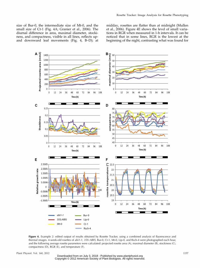
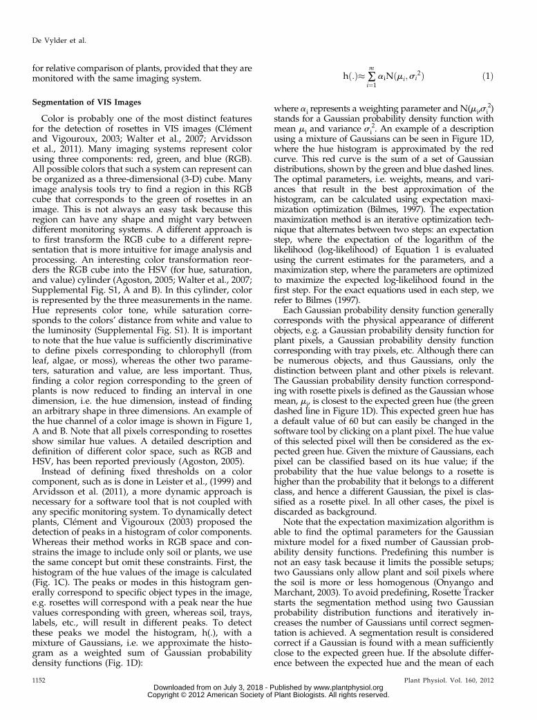
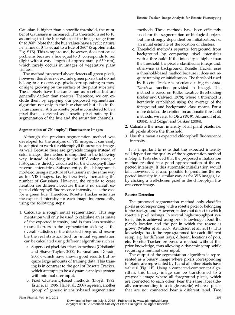
size of Bur-0, the intermediate size of Mt-0, and thesmall size of Ct-1 (Fig. 4A; Granier et al., 2006). Thediurnal difference in area, maximal diameter, stocki-ness, and compactness, visible in all lines, reflects up-and downward leaf movements (Fig. 4, B–D); at
midday, rosettes are flatter than at midnight (Mullenet al., 2006). Figure 4E shows the level of small varia-tions in RGR when measured in 1-h intervals. It can benoticed that in some lines, RGR is the lowest at thebeginning of the night, contrasting what was found for
Figure 4. Example 2: edited output of results obtained by Rosette Tracker, using a combined analysis of fluorescence andthermal images. 4-week-old rosettes of abi1-1, 35S::ABI5, Bur-0, Ct-1, Mt-0, Lip-0, and Rsch-4 were photographed each hour,and the following average rosette parameters were calculated: projected rosette area (A), maximal diameter (B), stockiness (C),compactness (D), RGR (E), and temperature (F).
Plant Physiol. Vol. 160, 2012 1157
Rosette Tracker: Image Analysis for Rosette Phenotyping
www.plantphysiol.orgon July 3, 2018 - Published by Downloaded from Copyright © 2012 American Society of Plant Biologists. All rights reserved.

circadian hypocotyl extension (Dowson-Day and Millar,1999). This readout may be influenced by the relativelymore compact appearance of the projected rosette image,which is related to the diurnal leaf movements (morehyponasty at night onset). The effect becomes evenclearer when 4-h intervals are used for determining RGR(Supplemental Fig. S3). In the 4-h interval measure-ments, there is a difference between Lip-0, with lowerRGR in the morning, and the other lines, most of whichhave a lower RGR at dusk. This can be directly related tothe leaf movements and consequent phase differencesbetween Lip-0 and the other lines regarding projectedleaf area, maximal diameter, stockiness (very clear), andcompactness (compare Fig. 4 with Supplemental Fig.S3). Optimal use of the RGR measurement tool in rela-tion to growth, therefore, is best suited for image se-quences with a 1-d interval (Supplemental Fig. S3).There it becomes apparent that during the experiment,there was an increase in RGR for the small rosettes ofLip-0, for the large rosettes of Bur-0, Mt-0, and 35S::ABI5,the RGR decreased, whereas the RGR remained, albeitwith some fluctuation, at the same level in the otherlines. Note that the first 24 h show “0” for RGR, becausethere was no available data for 24 h before the point ofmeasurement for comparison (Supplemental Fig. S3).
Analysis of IR images demonstrated that tempera-tures are lowest in abi1-1 mutants, indicating strongtranspiration (Fig. 4F). The Arabidopsis ecotypes areall warmer than abi1-1. Earlier observations haveshown similar transpiration rates for the ecotypes Bur-0,Mt-0, and Ct-1 (Granier et al., 2006). The abscisic acid-insensitive mutant abi1-1 is known to have reducedstomatal closure and should indeed appear colder inthermal images. By contrast, ABI5 does not influencewater loss from plants (Finkelstein, 1994); in this imagesequence, the values of the 35S::ABI5 are similar tothose of the wild-type ecotypes. Additionally, diurnaltemperature variation is observed, with peaks duringthe day, due to irradiation heat (Fig. 4F).
CONCLUSION
Rosette Tracker offers a user-friendly ImageJ plug-infor rapid analysis of rosette parameters. It is designedfor Arabidopsis but can work for any other rosetteplants species. The use is not limited to any specificindoor image acquisition hardware, lowering thethreshold for implementation in field experiments. Itcan be used to analyze size and temperature of singlesnapshots, including multiple rosettes and more com-plex time series with a high number of frames. Incombination with a standard to high-end camera sys-tem and modern PC, it is a powerful and affordabletool for plant growth evaluation.
MATERIALS AND METHODS
For Testing the Robustness against Different Cameras
A photograph of 34 Arabidopsis (Arabidopsis thaliana) rosettes was takenusing three different cameras: an Olympus C5050 camera, a Canon Powershot
SX110IS, and a built-in camera in an LG5000 mobile phone. The images werecaptured at a distance of 50 cm.
For Example 1
Arabidopsis Columbia-0 wild-type seeds were acquired from the Not-tingham Arabidopsis Stock Center. Plants were grown for 4 weeks in a growthroom with 22°C and 16-h/8-h light/dark cycles. Light intensity was 60 mmolm22 s21 from cool-white light tubes (Philips). A photograph was taken using aCanon 500D reflex camera with an 18- to 55-mm lens (www.Canon.com), at 55mm, from a distance of 50 cm. Image 1 used for this analysis can be found athttp://telin.ugent.be/~jdvylder/RosetteTracker.
For Example 2
Arabidopsis accessions and abi1-1 were acquired from the NottinghamArabidopsis Stock Center. 35S::ABI5 was kindly provided by J. Smalle. Plantswere grown in trays for 3 weeks in 13-h/11-h light/dark cycles in a growthroom at 21°C. Daytime photosynthetic photon flux density was 150 mmol m22
s21. Rosettes were photographed every hour by a robotized camera system(Chaerle et al., 2006). Fluorescence images were acquired with an in-house-developed fluorescence imaging system (Chaerle et al., 2004), whereas thermalimages were acquired with a FLIR-AGEMA Thermovision THV900SWTE (FlirSystems). The output files (supplemental data/online) were rearranged, andaverage values were calculated from up to eight replicate plants, dependingon the genotype (Supplemental Document S3). A compilation of all unarrangedmeasurements, photographs, and configuration files used for this example canbe downloaded from http://telin.ugent.be/~jdvylder/RosetteTracker.
Supplemental Data
The following materials are available in the online version of this article.
Supplemental Figure S1. Two possible representations of color and exam-ples of the representation of a VIS image in HSV color space.
Supplemental Figure S2. The relation between scale and error on areameasurements.
Supplemental Figure S3. Comparison of RGR results using different timeintervals.
Supplemental Document S1. Quick-start guide for new users.
Supplemental Document S2. Work flow for Example 1.
Supplemental Document S3. Measurements for Example 2.
ACKNOWLEDGMENTS
The authors wish to thank Pieter Callebert, Laury Chaerle, and XavierVanrobaeys for setup and image acquisition of the time-lapse sequence inExample 2. Supplemental Figure S1, A and B, is modified from the works ofMichael Horvath.
Received June 28, 2012; accepted August 30, 2012; published August 31, 2012.
LITERATURE CITED
Aboelela A, Liptay A, Barron JL (2005) Plant growth measurement tech-niques using near-infrared imagery. Int J Robot Autom 20: 42–49
Abràmoff MD, Magalhães PJ, Ram SJ (2004) Image processing with Im-ageJ. Biophotonics Int 11: 36–42
Agoston MK (2005) Computer Graphics and Geometric Modeling: Im-plementation and Algorithms. Springer, London
Arvidsson S, Pérez-Rodríguez P, Mueller-Roeber B (2011) A growthphenotyping pipeline for Arabidopsis thaliana integrating image anal-ysis and rosette area modeling for robust quantification of genotypeeffects. New Phytol 191: 895–907
Bader M (2012) How to calibrate a monocular camera. ROS Tutorials.http://www.ros.org/wiki/camera_calibration/Tutorials/MonocularCalibration(September 24, 2012)
1158 Plant Physiol. Vol. 160, 2012
De Vylder et al.
www.plantphysiol.orgon July 3, 2018 - Published by Downloaded from Copyright © 2012 American Society of Plant Biologists. All rights reserved.

Baecker V (2007) Automatic measurement of plant features using ImageJand MRI Cell Image Analyzer. In Workshop on Growth Phenotypingand Imaging in Plants. AGRON-OMICS, Montpellier, France, p 17
Barron JL, Liptay A (1994) Optic flow to measure minute increments inplant growth. Bioimaging 2: 57–61
Barron JL, Liptay A (1997) Measuring 3D plant growth using optical flow.Bioimaging 5: 82–86
Beatson RK, Powell MJD, Tan AM (2007) Fast evaluation of polyharmonicsplines in three dimensions. IMA J Numer Anal 27: 427–450
Bilmes JA (1997) A gentle tutorial on the EM algorithm and its applicationto parameter estimation for gaussian mixture and hidden markovmodels. ICSI-TR-97-021 Technical Report. International Computer Sci-ence Institute, Berkeley, CA
Blackman VH (1919) The compound interest law and plant growth. AnnBot (Lond) 33: 353–360
Bookstein FL (1989) Principal warps: thin-plate splines and the decompo-sition of deformations. IEEE Trans Pattern Anal Mach Intell 11: 567–585
Chaerle L, Hagenbeek D, De Bruyne E, Valcke R, Van Der Straeten D(2004) Thermal and chlorophyll-fluorescence imaging distinguish plant-pathogen interactions at an early stage. Plant Cell Physiol 45: 887–896
Chaerle L, Hagenbeek D, Van der Straeten D, Leinonen I, Jones H (2006)Monitoring and screening plant populations with thermal and chloro-phyll fluorescence imaging. Comp Biochem Physiol A Mol IntegrPhysiol 143: S143–S144
Chaerle L, Leinonen I, Jones HG, Van Der Straeten D (2007) Monitoringand screening plant populations with combined thermal and chloro-phyll fluorescence imaging. J Exp Bot 58: 773–784
Clément A, Vigouroux B (2003) Unsupervised segmentation of scenescontaining vegetation (Forsythia) and soil by hierarchical analysis of bi-dimensional histograms. Pattern Recognit Lett 24: 1951–1957
Cristianini N, Shawe-Taylor J (2000) An Introduction to Support VectorMachines: and Other Kernel-Based Learning Methods. CambridgeUniversity Press, Cambridge, UK
De Vylder J, Douterloigne K, Vandenbussche F, Van Der Straeten D,Philips W (2012) A non-rigid registration method for multispectralimaging of plants. In Sensing for Agriculture and Food Quality andSafety: Proceedings of the Society of Photo-Optical InstrumentationEngineers (SPIE). SPIE, Baltimore, MD, pp 1–8
Dhondt S, Van Haerenborgh D, Van Cauwenbergh C, Merks RMH, PhilipsW, Beemster GTS, Inzé D (2012) Quantitative analysis of venation patternsof Arabidopsis leaves by supervised image analysis. Plant J 69: 553–563
Dowson-Day MJ, Millar AJ (1999) Circadian dysfunction causes aberranthypocotyl elongation patterns in Arabidopsis. Plant J 17: 63–71
Ester M, Kriegel H-P, Sander J, Xu X (1996) A density-based algorithm fordiscovering clusters in large spatial databases with noise. In E Simoudis,J Han, UM Fayyad, eds, International Conference on Knowledge Dis-covery and Data Mining (KDD-96). The Association for the Advance-ment of Artificial Intelligence, Portland, OR, pp 226–231
Finkelstein RR (1994) Mutations at two new Arabidopsis ABA responseloci are similar to the abi3 mutations. Plant J 5: 765–771
French A, Ubeda-Tomás S, Holman TJ, Bennett MJ, Pridmore T (2009)High-throughput quantification of root growth using a novel image-analysis tool. Plant Physiol 150: 1784–1795
Granier C, Aguirrezabal L, Chenu K, Cookson SJ, Dauzat M, Hamard P,Thioux JJ, Rolland G, Bouchier-Combaud S, Lebaudy A, et al (2006)PHENOPSIS, an automated platform for reproducible phenotyping ofplant responses to soil water deficit in Arabidopsis thaliana permittedthe identification of an accession with low sensitivity to soil water def-icit. New Phytol 169: 623–635
Guyer DE, Miles GE, Schreiber MM, Mitchell OR, Vanderbilt VC (1986)Machine vision and image processing for plant identification. TransASABE 29: 1500–1507
Hall M, Frank E, Holmes G, Pfahringer B, Reutemann P, Witten IH (2009)The WEKA data mining software: an update. SIGKDD Explor 11: 10–18
Jaffe MJ, Wakefield AH, Telewski F, Gulley E, Biro R (1985) Computer-assisted image analysis of plant growth, thigmomorphogenesis andgravitropism. Plant Physiol 77: 722–730
Jansen M, Gilmer F, Biskup B, Nagel KA, Rascher U, Fischbach A, BriemS, Dreissen G, Tittmann S, Braun S, et al (2009) Simultaneous pheno-typing of leaf growth and chlorophyll fluorescence via GROWSCREENFLUORO allows detection of stress tolerance in Arabidopsis thaliana andother rosette plants. Funct Plant Biol 36: 902–914
Leister D, Varotto C, Pesaresi P, Niwergall A, Salamini F (1999) Large-scale evaluation of plant growth in Arabidopsis thaliana by non-invasive image analysis. Plant Physiol Biochem 37: 671–678
Lloyd SP (1982) Least-squares quantization in PCM. IEEE Trans Inf Theory28: 129–137
Merks RMH, Guravage M, Inzé D, Beemster GTS (2011) VirtualLeaf: anopen-source framework for cell-based modeling of plant tissue growthand development. Plant Physiol 155: 656–666
Mullen JL, Weinig C, Hangarter RP (2006) Shade avoidance and the reg-ulation of leaf inclination in Arabidopsis. Plant Cell Environ 29: 1099–1106
Onyango CM, Marchant JA (2001) Physics-based colour image segmenta-tion for scenes containing vegetation and soil. Image Vis Comput 19:523–538
Onyango CM, Marchant JA (2003) Segmentation of row crop plantsfrom weeds using colour and morphology. Comput Electron Agric39: 141–155
Otsu N (1979) A threshold selection method from gray-level histograms.IEEE Trans Syst Man Cybern 9:62–66
Price CA, Symonova O, Mileyko Y, Hilley T, Weitz JS (2011) Leaf ex-traction and analysis framework graphical user interface: segmentingand analyzing the structure of leaf veins and areoles. Plant Physiol 155:236–245
Rabunal JR, Dorado J (2006) Artificial Neural Networks in Real-Life Ap-plications. Idea Group, Hershey, PA
Ridler TW, Calvard S (1978) Picture thresholding using an iterative se-lection method. IEE Trans Syst Man Cybern 8: 630–632
Russ JC (2011) The Image Processing Handbook, Ed 6. CRC Press, BocaRaton, FL
Schmundt D, Stitt M, Jähne B, Schurr U (1998) Quantitative analysis of thelocal rates of growth of dicot leaves at a high temporal and spatialresolution, using image sequence analysis. Plant J 16: 505–514
Sezgin M, Sankur B (2004) Survey over image thresholding techniques andquantitative performance evaluation. J Electron Imaging 13: 146–165
Shamir L, Delaney JD, Orlov N, Eckley DM, Goldberg IG (2010) Patternrecognition software and techniques for biological image analysis. PLoSComput Biol 6: e1000974
Shimizu H, Heins RD (1995) Computer-vision-based system for plantgrowth analysis. Trans ASABE 38: 959–964
Shu C, Brunton A, Fiala M (2003) Automatic grid finding in calibrationpatterns using Delaunay triangulation. Technical Report. National Re-search Council, Ottawa, Canada
Walter A, Jansen M, Gilmer F, Biskup B, Nagel KA, Rascher U, Fischbach A,Briem S, Dreissen G, Tittmann S, et al (2009) Simultaneous phenotyping ofleaf growth and chlorophyll fluorescence via GROWSCREEN FLUORO al-lows detection of stress tolerance in Arabidopsis thaliana and other rosetteplants. Funct Plant Biol 36: 902–914
Walter A, Scharr H, Gilmer F, Zierer R, Nagel KA, Ernst M, Wiese A,Virnich O, Christ MM, Uhlig B, et al (2007) Dynamics of seedlinggrowth acclimation towards altered light conditions can be quantifiedvia GROWSCREEN: a setup and procedure designed for rapid opticalphenotyping of different plant species. New Phytol 174: 447–455
Plant Physiol. Vol. 160, 2012 1159
Rosette Tracker: Image Analysis for Rosette Phenotyping
www.plantphysiol.orgon July 3, 2018 - Published by Downloaded from Copyright © 2012 American Society of Plant Biologists. All rights reserved.