rosemount 485 annubar primary - fmtech annubar flow element.pdf · • sensor size 2: 6-in. to...
TRANSCRIPT
Product Data Sheet00813-0100-4809, Rev EA
Catalog 2006 - 2007The Annubar Flowmeter Series
44
Rosemount 485 Annubar Primary
SPECIFICATIONS
Performance
Performance Statement Assumptions
Measured pipe I.D.
Discharge Coefficient Factor
±0.75% of flow rate
Repeatability
±0.1%
Line Sizes
• Sensor Size 1: 2-in. to 8-in. (50 to 200 mm)
• Sensor Size 2: 6-in. to 96-in. (150 to 2400 mm)
• Sensor Size 3: 12-in. to 96-in. (300 to 2400 mm)
NOTE
Some mounting types are not available in larger line sizes.
TABLE 26. Reynolds Number and Probe Width
Sizing
Contact an Emerson Process Management representative for
assistance. A Configuration Data Sheet is required prior to order
for application verification.
Flow Turndown
10:1or better
Annubar Sensor Surface Finish
The front surface of the Annubar primary is textured for high
Reynolds number applications (typically gas and steam). The
surface texture creates a more turbulent boundary layer on the
front surface of the sensor. The increased turbulence produces a
more predictable and repeatable separation of flow at the edge of
the sensor. The appropriate surface finish will be determined for
each application by the Emerson Process Management sizing
program.
Functional
Service
• Liquid
• Gas
• Steam
Process Temperature Limits
Direct Mount Electronics
• 500 °F (260 °C)
• 750 °F (400 °C) when used with a direct mount, high
temperature 5-valve manifold (Electronics Connection
Platform code 6)
Remote Mount Electronics
• 1250 °F (677 °C) – Hastelloy Sensor Material
• 850 °F (454 °C) – Stainless Steel Sensor Material
Pressure and Temperature Limits(1)
Direct Mount Electronics
• Up to 600# ANSI (1440 psig at 100 °F (99 bar at 38 °C))
• Integral temperature measurement is not available with
Flanged mounting type greater than class 600
Remote Mount Electronics
• Up to 2500# ANSI (6000 psig at 100 °F (416 bar at 38 °C)).
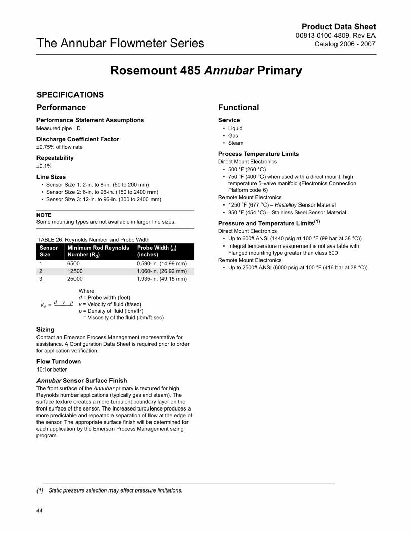
Sensor
Size
Minimum Rod Reynolds
Number (Rd)
Probe Width (d)
(inches)
1 6500 0.590-in. (14.99 mm)
2 12500 1.060-in. (26.92 mm)
3 25000 1.935-in. (49.15 mm)
Where
d = Probe width (feet)
v = Velocity of fluid (ft/sec)
p = Density of fluid (lbm/ft3)
= Viscosity of the fluid (lbm/ft-sec)
Rd
d v p
---------------------=
(1) Static pressure selection may effect pressure limitations.
Product Data Sheet00813-0100-4809, Rev EA
Catalog 2006 - 2007
45
The Annubar Flowmeter Series
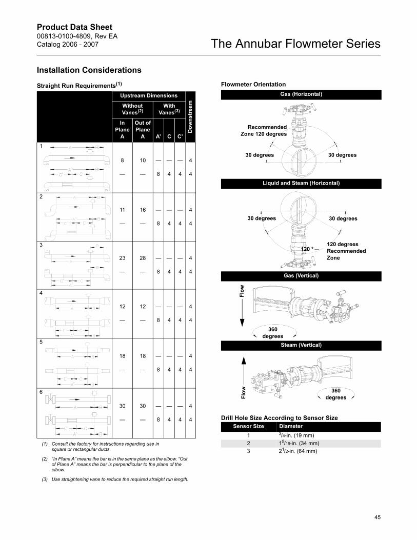
Installation Considerations
Drill Hole Size According to Sensor Size
Straight Run Requirements(1)
(1) Consult the factory for instructions regarding use in square or rectangular ducts.
Upstream Dimensions
Do
wn
str
ea
mWithout
Vanes(2)
(2) “In Plane A” means the bar is in the same plane as the elbow. “Out of Plane A” means the bar is perpendicular to the plane of the elbow.
With
Vanes(3)
(3) Use straightening vane to reduce the required straight run length.
In
Plane
A
Out of
Plane
A A’ C C’
1
8
—
10
—
—
8
—
4
—
4
4
4
2
11
—
16
—
—
8
—
4
—
4
4
4
3
23
—
28
—
—
8
—
4
—
4
4
4
4
12
—
12
—
—
8
—
4
—
4
4
4
5
18
—
18
—
—
8
—
4
—
4
4
4
6
30
—
30
—
—
8
—
4
—
4
4
4
Flowmeter Orientation
Gas (Horizontal)
Liquid and Steam (Horizontal)
Gas (Vertical)
Steam (Vertical)
Sensor Size Diameter
1 3/4-in. (19 mm)
2 15/16-in. (34 mm)
3 21/2-in. (64 mm)
30 degrees 30 degrees
Recommended
Zone 120 degrees
30 degrees 30 degrees
120 °120 degrees
Recommended
Zone
Flo
w
360
degrees
360
degreesFlo
w
Product Data Sheet00813-0100-4809, Rev EA
Catalog 2006 - 2007The Annubar Flowmeter Series
46
Physical
Temperature Measurement
Integral RTD
• 100 Ohm platinum RTD
• 4-wire RTD ( = 0.00385)
Remote RTD
• 100 Ohm platinum RTD, spring loaded with 1/2-in.
NPT nipple and union (078 series with Rosemount 644
housing)
• Remote RTD material is the same as the specified
pipe material
Thermowell
• 1/2-in. x 1/2-in NPT, 316 Stainless Steel with 1/2-in. Carbon Steel
weld couplet.
Electronic Connections1/2–14 NPT, G1/2, and M20 × 1.5 (CM20) conduit. HART interface
connections fixed to terminal block for output code A
Annubar Sensor Material
• 316 Stainless Steel
• Hastelloy 276
Annubar Type
See “Dimensional Drawings” on page 48
Pak-Lok Model (option P)
• Provided with a compression sealing mechanism rated up to
600# ANSI (1440 psig at 100 °F (99 bar at 38 °C))
• Graphite Packing (–300 to 850 °F (–184 to 454 °C))
Flanged with Opposite Side Support Model (option F)
• Provided with opposite side support, which is the same
material as the pipe and requires a second pipe penetration
• Sensor flange is the same material as the Annubar sensor and
the mounting flange is the same material as the pipe material
• Flanged mounting hardware: nuts, bolts and gaskets
(constructed from the same material as the pipe material)
• SST: (–300 to 850 °F (–184 to 454 °C))
• Hastelloy: (–300 to 1250 °F (–184 to 677 °C))
Flange–Lok Model (option L)
• Flange–Lok assembly is supplied in 316 SST material.
• Flange-Lok mounting hardware: nuts, bolts and gaskets
(constructed from the same material as the pipe material)
• –300 to 850 °F (–184 to 454 °C)
Flo-Tap Models (options G and M)
• Opposite side support is not available
• Threaded connection is not available with Sensor Size 3
• Gear Drive is not available with Sensor Size 1
• Packing gland required
• Packing Gland Material Temperature Limits
• Teflon® (PTFE): –40 to 400 °F (–40 to 204 °C)
• Graphite: –300 to 850 °F (–184 to 454 °C)
• Isolation valve included
• The isolation valve will carry the same pressure rating as the
sensor flange and mounting flange specified in the mounting
type
• Ball valves have a 300# limitation
• For threaded flo-tap models, the isolation valve NPT size is
11/4-in. (Sensor Size one) and 2-in. (Sensor Size 2).
Annubar Type Specification Chart
Instrument Connections Temperature Ranges
Option
Code Description Pa
k-L
ok(1)
(1) Available up to 600# ANSI (1440 psig at 100 °F (99 bar at 38 °C)) rating.
Fla
ng
e-L
ok
Fla
ng
e
Ma
nu
al a
nd
Ge
ar
Dri
ve
Flo
-Ta
p
T1(1) Pak-Lok Body X
Threaded connection X
A1 150# RF ANSI X X X
A3 300# RF ANSI X X X
A6 600# RF ANSI X X X
A9(2)
(2) Remote mount only.
900# RF ANSI X
AF(2) 1500# RF ANSI X
AT(2) 2500# RF ANSI X
D1 DN PN 16 X X X
D3 DN PN 40 X X X
D6 DN PN 100 X X X
R9(2) 900# RTJ Flange X
RF(2) 1500# RTJ Flange X
RT(2) 2500# RTJ Flange X
TABLE 27. Minimum / Maximum Temperature Range
Code Description Temperature
G1 Needle Valves, Carbon Steel –20 to 500 °F
(–29 to 260 °C)
G2 Needle Valves, Stainless Steel –40 to 600 °F
(–40 to 316 °C)
G3 Needle Valves, Hastelloy –40 to 600 °F
(–40 to 316 °C)
G5 OS&Y Gate Valve, Carbon Steel –20 to 775 °F
(–29 to 413 °C)
G6 OS&Y Gate Valve, Stainless Steel –40 to 850 °F
(–40 to 454 °C)
G7 OS&Y Gate Valve, Hastelloy –40 to 1250 °F
(–40 to 677 °C)
Product Data Sheet00813-0100-4809, Rev EA
Catalog 2006 - 2007
47
The Annubar Flowmeter Series
Flowmeter Installed in Flanged Pipe Spool Section
(option codes H3, H4, and H5)
• All pipe spool sections are flanged pipe sections
• The flanged pipe spool section is constructed from the same
material as the pipe
• Consult the factory for remote temperature measurement and
ANSI ratings above 600# and DIN flanges.
TABLE 28. Flanged Pipe Spool Section Schedule
ANSI Schedule
150# ANSI 40
300# ANSI 40
600# ANSI 80
TABLE 29. Flange Pipe Spool Section Length
Nominal Pipe Size Length
2-in. (50 mm) 10.52-in. (267.2 mm)
3-in. (80 mm) 11.37-in. (288.8 mm)
4-in. (100 mm) 12.74-in. (323.6 mm)
6-in. (150 mm) 14.33-in. (364.0 mm)
8-in. (200 mm) 16.58-in. (421.1 mm)
Product Data Sheet00813-0100-4809, Rev EA
Catalog 2006 - 2007The Annubar Flowmeter Series
48
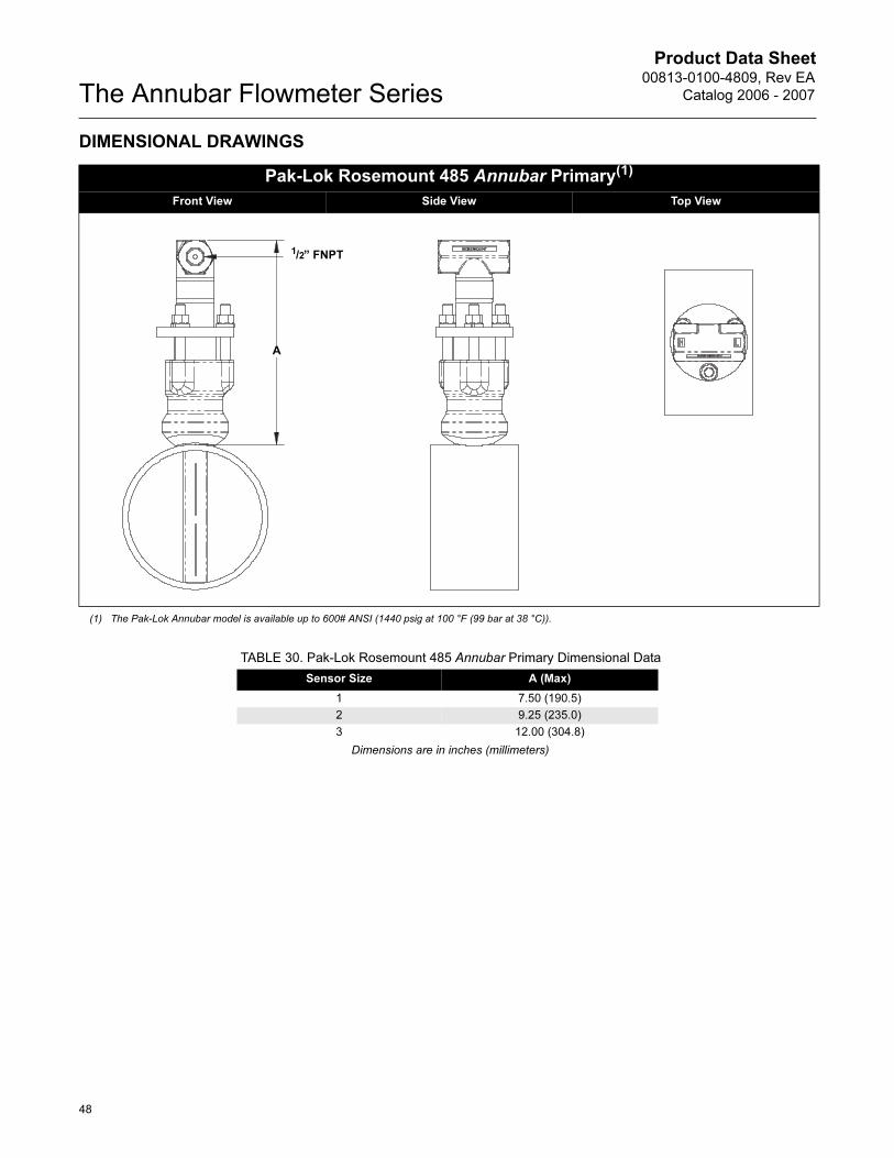
DIMENSIONAL DRAWINGS
Pak-Lok Rosemount 485 Annubar Primary(1)
Front View Side View Top View
(1) The Pak-Lok Annubar model is available up to 600# ANSI (1440 psig at 100 °F (99 bar at 38 °C)).
A
1/2” FNPT
TABLE 30. Pak-Lok Rosemount 485 Annubar Primary Dimensional Data
Sensor Size A (Max)
1 7.50 (190.5)
2 9.25 (235.0)
3 12.00 (304.8)
Dimensions are in inches (millimeters)
Product Data Sheet00813-0100-4809, Rev EA
Catalog 2006 - 2007
49
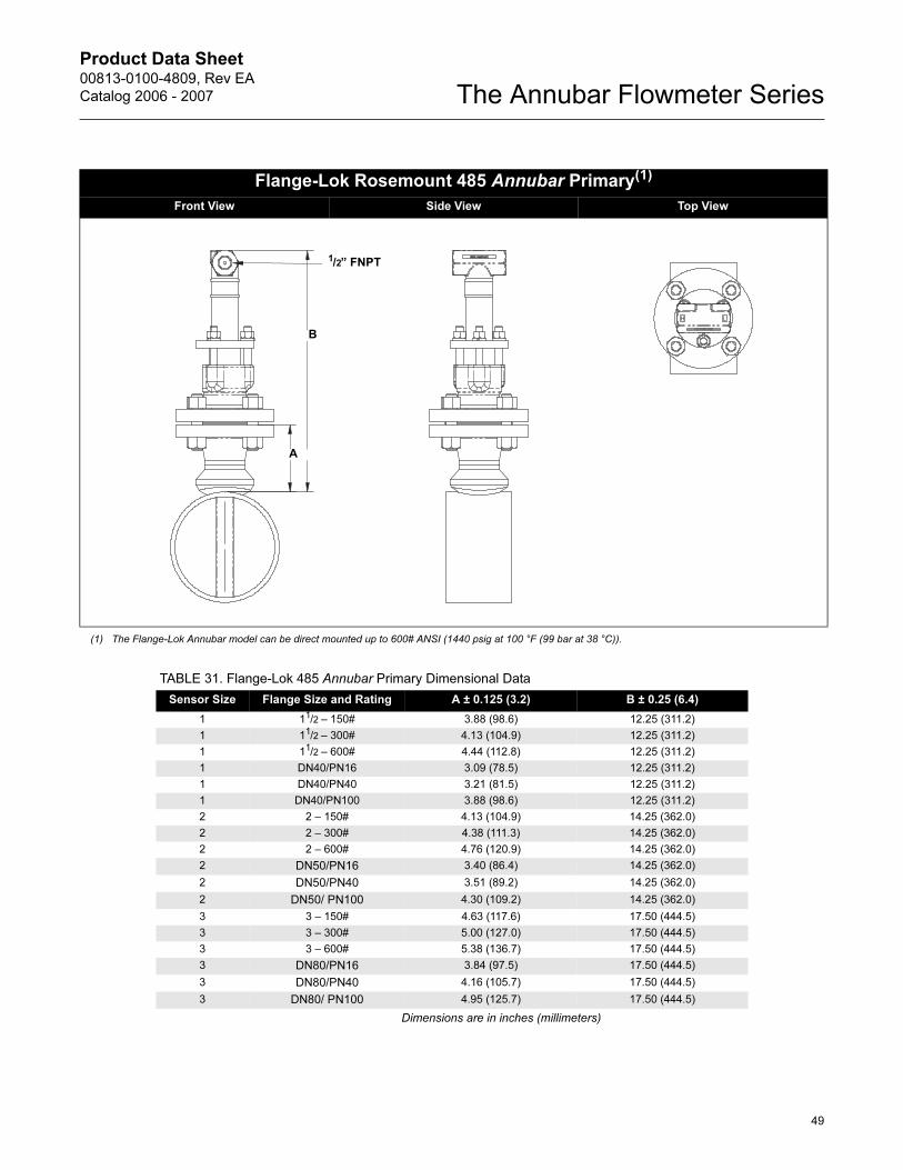
The Annubar Flowmeter Series
Flange-Lok Rosemount 485 Annubar Primary(1)
Front View Side View Top View
(1) The Flange-Lok Annubar model can be direct mounted up to 600# ANSI (1440 psig at 100 °F (99 bar at 38 °C)).
B
A
1/2” FNPT
TABLE 31. Flange-Lok 485 Annubar Primary Dimensional Data
Sensor Size Flange Size and Rating A ± 0.125 (3.2) B ± 0.25 (6.4)
1 11/2 – 150# 3.88 (98.6) 12.25 (311.2)
1 11/2 – 300# 4.13 (104.9) 12.25 (311.2)
1 11/2 – 600# 4.44 (112.8) 12.25 (311.2)
1 DN40/PN16 3.09 (78.5) 12.25 (311.2)
1 DN40/PN40 3.21 (81.5) 12.25 (311.2)
1 DN40/PN100 3.88 (98.6) 12.25 (311.2)
2 2 – 150# 4.13 (104.9) 14.25 (362.0)
2 2 – 300# 4.38 (111.3) 14.25 (362.0)
2 2 – 600# 4.76 (120.9) 14.25 (362.0)
2 DN50/PN16 3.40 (86.4) 14.25 (362.0)
2 DN50/PN40 3.51 (89.2) 14.25 (362.0)
2 DN50/ PN100 4.30 (109.2) 14.25 (362.0)
3 3 – 150# 4.63 (117.6) 17.50 (444.5)
3 3 – 300# 5.00 (127.0) 17.50 (444.5)
3 3 – 600# 5.38 (136.7) 17.50 (444.5)
3 DN80/PN16 3.84 (97.5) 17.50 (444.5)
3 DN80/PN40 4.16 (105.7) 17.50 (444.5)
3 DN80/ PN100 4.95 (125.7) 17.50 (444.5)
Dimensions are in inches (millimeters)
Product Data Sheet00813-0100-4809, Rev EA
Catalog 2006 - 2007The Annubar Flowmeter Series
50
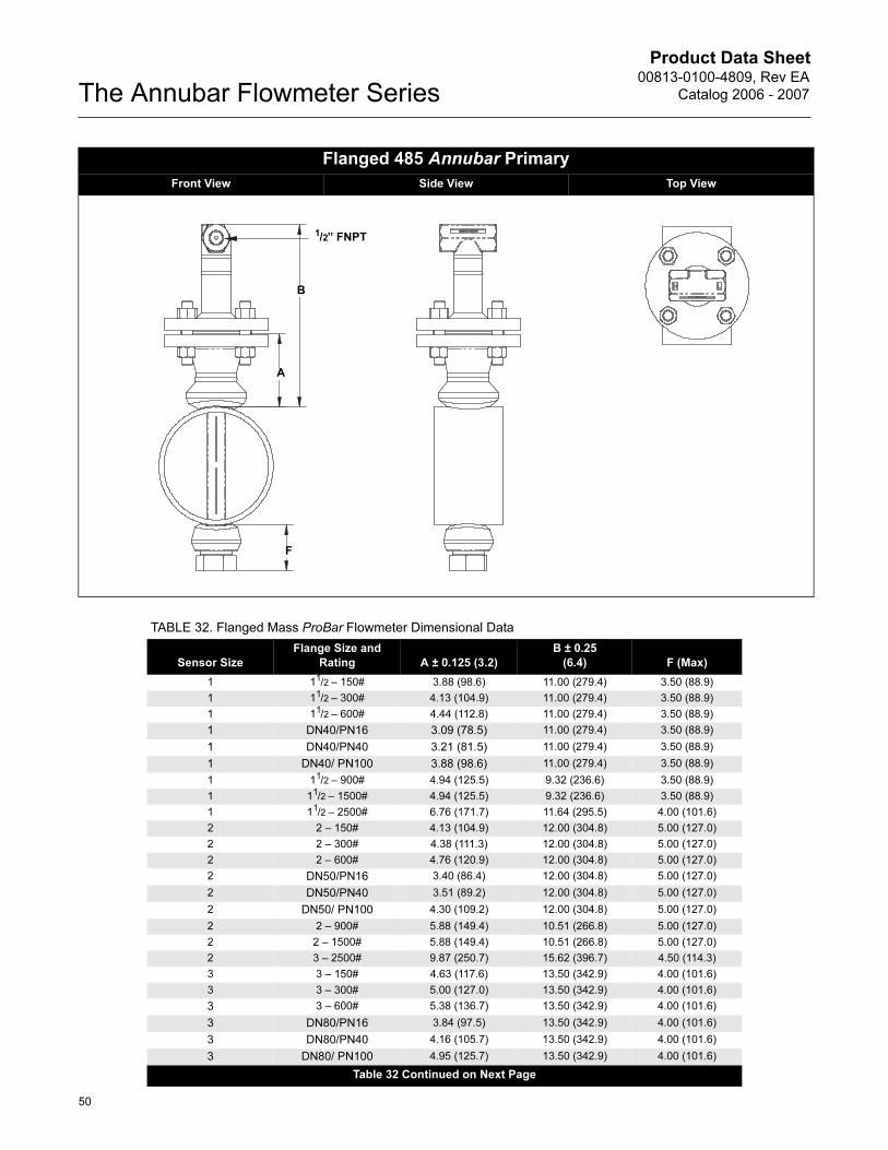
Flanged 485 Annubar Primary
Front View Side View Top View
B
A
F
1/2” FNPT
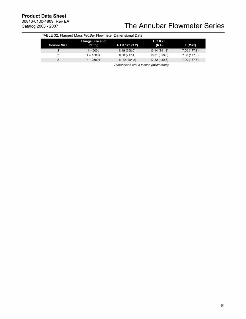
TABLE 32. Flanged Mass ProBar Flowmeter Dimensional Data
Sensor Size
Flange Size and
Rating A ± 0.125 (3.2)
B ± 0.25
(6.4) F (Max)
1 11/2 – 150# 3.88 (98.6) 11.00 (279.4) 3.50 (88.9)
1 11/2 – 300# 4.13 (104.9) 11.00 (279.4) 3.50 (88.9)
1 11/2 – 600# 4.44 (112.8) 11.00 (279.4) 3.50 (88.9)
1 DN40/PN16 3.09 (78.5) 11.00 (279.4) 3.50 (88.9)
1 DN40/PN40 3.21 (81.5) 11.00 (279.4) 3.50 (88.9)
1 DN40/ PN100 3.88 (98.6) 11.00 (279.4) 3.50 (88.9)
1 11/2 – 900# 4.94 (125.5) 9.32 (236.6) 3.50 (88.9)
1 11/2 – 1500# 4.94 (125.5) 9.32 (236.6) 3.50 (88.9)
1 11/2 – 2500# 6.76 (171.7) 11.64 (295.5) 4.00 (101.6)
2 2 – 150# 4.13 (104.9) 12.00 (304.8) 5.00 (127.0)
2 2 – 300# 4.38 (111.3) 12.00 (304.8) 5.00 (127.0)
2 2 – 600# 4.76 (120.9) 12.00 (304.8) 5.00 (127.0)
2 DN50/PN16 3.40 (86.4) 12.00 (304.8) 5.00 (127.0)
2 DN50/PN40 3.51 (89.2) 12.00 (304.8) 5.00 (127.0)
2 DN50/ PN100 4.30 (109.2) 12.00 (304.8) 5.00 (127.0)
2 2 – 900# 5.88 (149.4) 10.51 (266.8) 5.00 (127.0)
2 2 – 1500# 5.88 (149.4) 10.51 (266.8) 5.00 (127.0)
2 3 – 2500# 9.87 (250.7) 15.62 (396.7) 4.50 (114.3)
3 3 – 150# 4.63 (117.6) 13.50 (342.9) 4.00 (101.6)
3 3 – 300# 5.00 (127.0) 13.50 (342.9) 4.00 (101.6)
3 3 – 600# 5.38 (136.7) 13.50 (342.9) 4.00 (101.6)
3 DN80/PN16 3.84 (97.5) 13.50 (342.9) 4.00 (101.6)
3 DN80/PN40 4.16 (105.7) 13.50 (342.9) 4.00 (101.6)
3 DN80/ PN100 4.95 (125.7) 13.50 (342.9) 4.00 (101.6)
Table 32 Continued on Next Page
Product Data Sheet00813-0100-4809, Rev EA
Catalog 2006 - 2007
51
The Annubar Flowmeter Series
3 4 – 900# 8.19 (208.0) 13.44 (341.3) 7.00 (177.8)
3 4 – 1500# 8.56 (217.4) 13.81 (350.8) 7.00 (177.8)
3 4 – 2500# 11.19 (284.2) 17.32 (439.8) 7.00 (177.8)
Dimensions are in inches (millimeters)
TABLE 32. Flanged Mass ProBar Flowmeter Dimensional Data
Sensor Size
Flange Size and
Rating A ± 0.125 (3.2)
B ± 0.25
(6.4) F (Max)
Product Data Sheet00813-0100-4809, Rev EA
Catalog 2006 - 2007The Annubar Flowmeter Series
52
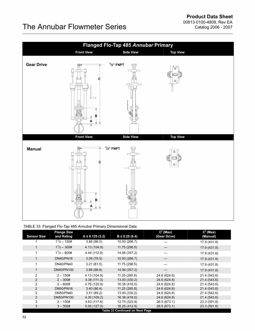
Flanged Flo-Tap 485 Annubar Primary
Front View Side View Top View
Front View Side View Top View
Gear Drive
C
B
A
1/2” FNPT
C
B
A
Manual1/2” FNPT
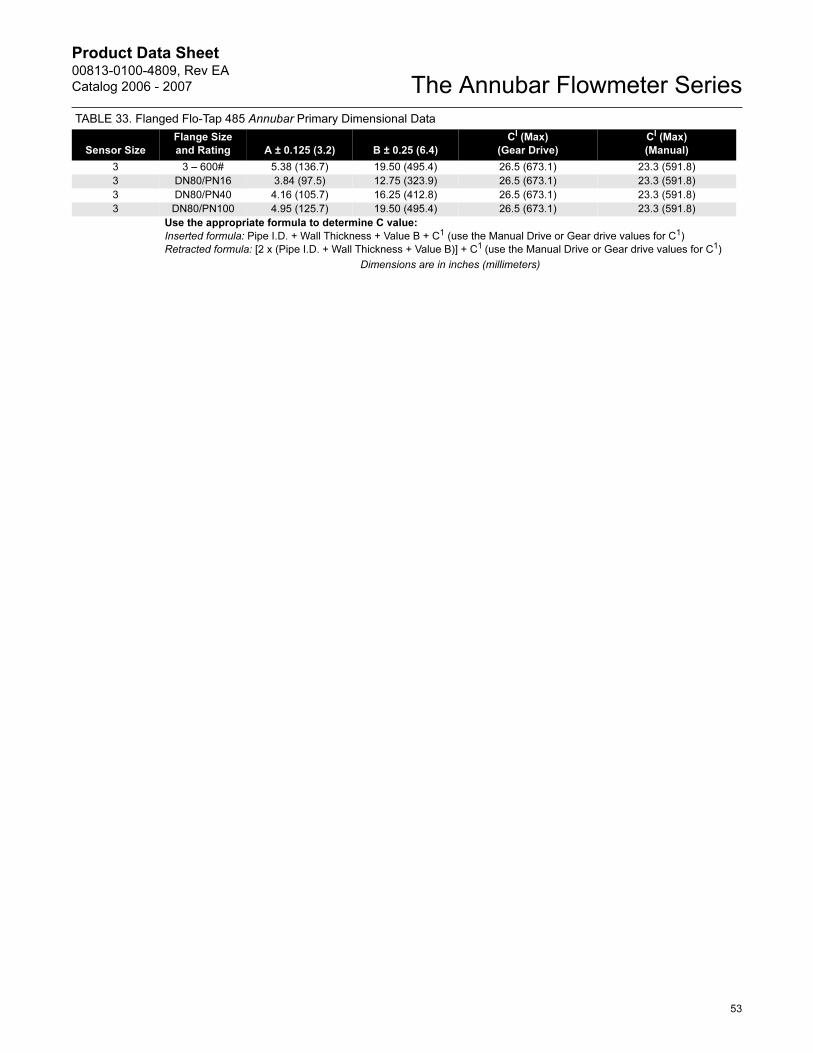
TABLE 33. Flanged Flo-Tap 485 Annubar Primary Dimensional Data
Sensor Size
Flange Size
and Rating A ± 0.125 (3.2) B ± 0.25 (6.4)
CI (Max)
(Gear Drive)
CI (Max)
(Manual)
1 11/2 – 150# 3.88 (98.5) 10.50 (266.7) — 17.9 (431.8)
1 11/2 – 300# 4.13 (104.9) 11.75 (298.5) — 17.9 (431.8)
1 11/2 – 600# 4.44 (112.8) 14.06 (357.2) — 17.9 (431.8)
1 DN40/PN16 3.09 (78.5) 10.50 (266.7) — 17.9 (431.8)
1 DN40/PN40 3.21 (81.5) 11.75 (298.5) — 17.9 (431.8)
1 DN40/PN100 3.88 (98.6) 14.06 (357.2) — 17.9 (431.8)
2 2 – 150# 4.13 (104.9) 11.25 (285.8) 24.6 (624.8) 21.4 (543.6)
2 2 – 300# 4.38 (111.3) 13.00 (330.2) 24.6 (624.8) 21.4 (543.6)
2 2 – 600# 4.76 (120.9) 16.38 (416.0) 24.6 (624.8) 21.4 (543.6)
2 DN50/PN16 3.40 (86.4) 11.25 (285.8) 24.6 (624.8) 21.4 (543.6)
2 DN50/PN40 3.51 (89.2) 13.00 (330.2) 24.6 (624.8) 21.4 (543.6)
2 DN50/PN100 4.30 (109.2) 16.38 (416.0) 24.6 (624.8) 21.4 (543.6)
3 3 – 150# 4.63 (117.6) 12.75 (323.9) 26.5 (673.1) 23.3 (591.8)
3 3 – 300# 5.00 (127.0) 16.25 (412.8) 26.5 (673.1) 23.3 (591.8)
Table 33 Continued on Next Page
Product Data Sheet00813-0100-4809, Rev EA
Catalog 2006 - 2007
53
The Annubar Flowmeter Series
3 3 – 600# 5.38 (136.7) 19.50 (495.4) 26.5 (673.1) 23.3 (591.8)
3 DN80/PN16 3.84 (97.5) 12.75 (323.9) 26.5 (673.1) 23.3 (591.8)
3 DN80/PN40 4.16 (105.7) 16.25 (412.8) 26.5 (673.1) 23.3 (591.8)
3 DN80/PN100 4.95 (125.7) 19.50 (495.4) 26.5 (673.1) 23.3 (591.8)
Use the appropriate formula to determine C value:
Inserted formula: Pipe I.D. + Wall Thickness + Value B + C1 (use the Manual Drive or Gear drive values for C1)
Retracted formula: [2 x (Pipe I.D. + Wall Thickness + Value B)] + C1 (use the Manual Drive or Gear drive values for C1)
Dimensions are in inches (millimeters)
TABLE 33. Flanged Flo-Tap 485 Annubar Primary Dimensional Data
Sensor Size
Flange Size
and Rating A ± 0.125 (3.2) B ± 0.25 (6.4)
CI (Max)
(Gear Drive)
CI (Max)
(Manual)
Product Data Sheet00813-0100-4809, Rev EA
Catalog 2006 - 2007The Annubar Flowmeter Series
54
Inserted, B Dimension = Pipe I.D. + Wall Thickness + A + BI
Retracted, B Dimension = 2 x (Pipe I.D. + Wall Thickness + A) + BI
Threaded Flo-Tap 485 Annubar Primary
Front View Side View Top View
Front View Side View Top View
TABLE 34. Threaded Flo-Tap 485 Annubar Primary Dimensional Data
Sensor Size
A ± 0.50
(12.7)
BI (Max)
(Gear Drive)
BI (Max)
(Manual)
1 6.76 (171.8) — 17.40 (442.0)
2 8.17 (207.5) 23.70 (602.0) 20.80 (528.3)
Sensor Size 3 is not available in a Threaded Flo-Tap.
Gear Drive
B
A
1/2” FNPT
B
A
Manual1/2” FNPT
Product Data Sheet00813-0100-4809, Rev EA
Catalog 2006 - 2007
55
The Annubar Flowmeter Series
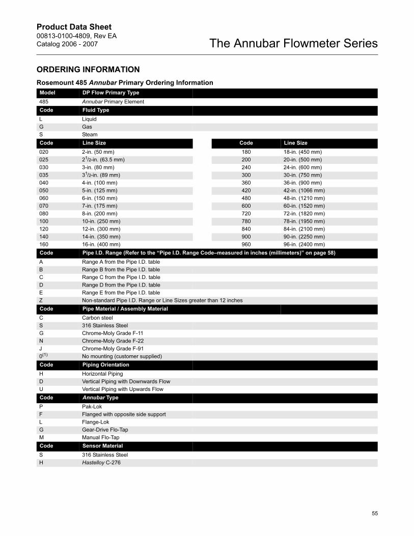
ORDERING INFORMATION
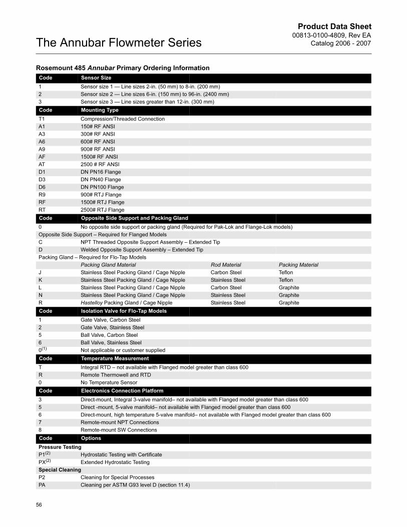
Rosemount 485 Annubar Primary Ordering Information
Model DP Flow Primary Type
485 Annubar Primary Element
Code Fluid Type
L Liquid
G Gas
S Steam
Code Line Size Code Line Size
020 2-in. (50 mm) 180 18-in. (450 mm)
025 21/2-in. (63.5 mm) 200 20-in. (500 mm)
030 3-in. (80 mm) 240 24-in. (600 mm)
035 31/2-in. (89 mm) 300 30-in. (750 mm)
040 4-in. (100 mm) 360 36-in. (900 mm)
050 5-in. (125 mm) 420 42-in. (1066 mm)
060 6-in. (150 mm) 480 48-in. (1210 mm)
070 7-in. (175 mm) 600 60-in. (1520 mm)
080 8-in. (200 mm) 720 72-in. (1820 mm)
100 10-in. (250 mm) 780 78-in. (1950 mm)
120 12-in. (300 mm) 840 84-in. (2100 mm)
140 14-in. (350 mm) 900 90-in. (2250 mm)
160 16-in. (400 mm) 960 96-in. (2400 mm)
Code Pipe I.D. Range (Refer to the “Pipe I.D. Range Code–measured in inches (millimeters)” on page 58)
A Range A from the Pipe I.D. table
B Range B from the Pipe I.D. table
C Range C from the Pipe I.D. table
D Range D from the Pipe I.D. table
E Range E from the Pipe I.D. table
Z Non-standard Pipe I.D. Range or Line Sizes greater than 12 inches
Code Pipe Material / Assembly Material
C Carbon steel
S 316 Stainless Steel
G Chrome-Moly Grade F-11
N Chrome-Moly Grade F-22
J Chrome-Moly Grade F-91
0(1) No mounting (customer supplied)
Code Piping Orientation
H Horizontal Piping
D Vertical Piping with Downwards Flow
U Vertical Piping with Upwards Flow
Code Annubar Type
P Pak-Lok
F Flanged with opposite side support
L Flange-Lok
G Gear-Drive Flo-Tap
M Manual Flo-Tap
Code Sensor Material
S 316 Stainless Steel
H Hastelloy C-276
Product Data Sheet00813-0100-4809, Rev EA
Catalog 2006 - 2007The Annubar Flowmeter Series
56
Code Sensor Size
1 Sensor size 1 — Line sizes 2-in. (50 mm) to 8-in. (200 mm)
2 Sensor size 2 — Line sizes 6-in. (150 mm) to 96-in. (2400 mm)
3 Sensor size 3 — Line sizes greater than 12-in. (300 mm)
Code Mounting Type
T1 Compression/Threaded Connection
A1 150# RF ANSI
A3 300# RF ANSI
A6 600# RF ANSI
A9 900# RF ANSI
AF 1500# RF ANSI
AT 2500 # RF ANSI
D1 DN PN16 Flange
D3 DN PN40 Flange
D6 DN PN100 Flange
R9 900# RTJ Flange
RF 1500# RTJ Flange
RT 2500# RTJ Flange
Code Opposite Side Support and Packing Gland
0 No opposite side support or packing gland (Required for Pak-Lok and Flange-Lok models)
Opposite Side Support – Required for Flanged Models
C NPT Threaded Opposite Support Assembly – Extended Tip
D Welded Opposite Support Assembly – Extended Tip
Packing Gland – Required for Flo-Tap Models
Packing Gland Material Rod Material Packing Material
J Stainless Steel Packing Gland / Cage Nipple Carbon Steel Teflon
K Stainless Steel Packing Gland / Cage Nipple Stainless Steel Teflon
L Stainless Steel Packing Gland / Cage Nipple Carbon Steel Graphite
N Stainless Steel Packing Gland / Cage Nipple Stainless Steel Graphite
R Hastelloy Packing Gland / Cage Nipple Stainless Steel Graphite
Code Isolation Valve for Flo-Tap Models
1 Gate Valve, Carbon Steel
2 Gate Valve, Stainless Steel
5 Ball Valve, Carbon Steel
6 Ball Valve, Stainless Steel
0(1) Not applicable or customer supplied
Code Temperature Measurement
T Integral RTD – not available with Flanged model greater than class 600
R Remote Thermowell and RTD
0 No Temperature Sensor
Code Electronics Connection Platform
3 Direct-mount, Integral 3-valve manifold– not available with Flanged model greater than class 600
5 Direct -mount, 5-valve manifold– not available with Flanged model greater than class 600
6 Direct-mount, high temperature 5-valve manifold– not available with Flanged model greater than class 600
7 Remote-mount NPT Connections
8 Remote-mount SW Connections
Code Options
Pressure Testing
P1(2) Hydrostatic Testing with Certificate
PX(2) Extended Hydrostatic Testing
Special Cleaning
P2 Cleaning for Special Processes
PA Cleaning per ASTM G93 level D (section 11.4)
Rosemount 485 Annubar Primary Ordering Information
Product Data Sheet00813-0100-4809, Rev EA
Catalog 2006 - 2007
57
The Annubar Flowmeter Series
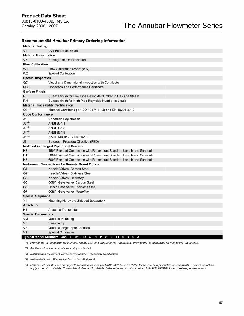
Material Testing
V1 Dye Penetrant Exam
Material Examination
V2 Radiographic Examination
Flow Calibration
W1 Flow Calibration (Average K)
WZ Special Calibration
Special Inspection
QC1 Visual and Dimensional Inspection with Certificate
QC7 Inspection and Performance Certificate
Surface Finish
RL Surface finish for Low Pipe Reynolds Number in Gas and Steam
RH Surface finish for High Pipe Reynolds Number in Liquid
Material Traceability Certification
Q8(3) Material Certificate per ISO 10474 3.1.B and EN 10204 3.1.B
Code Conformance
J1 Canadian Registration
J2(4) ANSI B31.1
J3(4) ANSI B31.3
J4(4) ANSI B31.8
J5(5) NACE MR-0175 / ISO 15156
J6 European Pressure Directive (PED)
Installed in Flanged Pipe Spool Section
H3 150# Flanged Connection with Rosemount Standard Length and Schedule
H4 300# Flanged Connection with Rosemount Standard Length and Schedule
H5 600# Flanged Connection with Rosemount Standard Length and Schedule
Instrument Connections for Remote Mount Option
G1 Needle Valves, Carbon Steel
G2 Needle Valves, Stainless Steel
G3 Needle Valves, Hastelloy
G5 OS&Y Gate Valve, Carbon Steel
G6 OS&Y Gate Valve, Stainless Steel
G7 OS&Y Gate Valve, Hastelloy
Special Shipment
Y1 Mounting Hardware Shipped Separately
Attach To
H1 Attach to Transmitter
Special Dimensions
VM Variable Mounting
VT Variable Tip
VS Variable length Spool Section
V9 Special Dimension
Typical Model Number: 485 L 060 D C H P S 2 T1 0 0 0 3
(1) Provide the “A” dimension for Flanged, Flange-Lok, and Threaded Flo-Tap models. Provide the “B” dimension for Flange Flo-Tap models.
(2) Applies to flow element only, mounting not tested.
(3) Isolation and Instrument valves not included in Traceability Certification.
(4) Not available with Electronics Connection Platform 6.
(5) Materials of Construction comply with recommendations per NACE MR0175/ISO 15156 for sour oil field production environments. Environmental limits apply to certain materials. Consult latest standard for details. Selected materials also conform to NACE MR0103 for sour refining environments.
Rosemount 485 Annubar Primary Ordering Information
Product Data Sheet00813-0100-4809, Rev EA
Catalog 2006 - 2007The Annubar Flowmeter Series
58
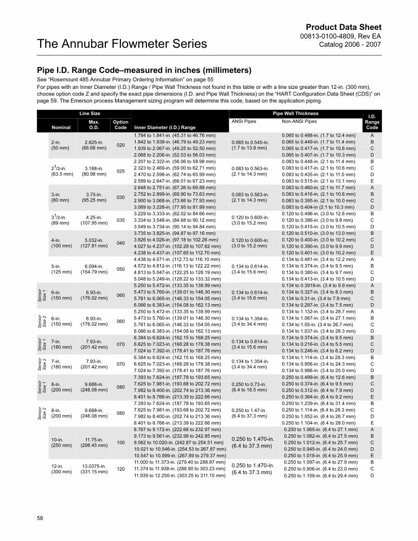
Pipe I.D. Range Code–measured in inches (millimeters)See “Rosemount 485 Annubar Primary Ordering Information” on page 55
For pipes with an Inner Diameter (I.D.) Range / Pipe Wall Thickness not found in this table or with a line size greater than 12-in. (300 mm),
choose option code Z and specify the exact pipe dimensions (I.D. and Pipe Wall Thickness) on the “HART Configuration Data Sheet (CDS)” on
page 59. The Emerson process Management sizing program will determine this code, based on the application piping.
Line Size
Inner Diameter (I.D.) Range
Pipe Wall ThicknessI.D.
Range CodeNominal
Max. O.D.
Option Code
ANSI Pipes Non-ANSI Pipes
2-in. (50 mm)
2.625-in. (66.68 mm)
020
1.784 to 1.841-in. (45.31 to 46.76 mm)
0.065 to 0.545-in. (1.7 to 13.8 mm)
0.065 to 0.488-in. (1.7 to 12.4 mm) A
1.842 to 1.938-in. (46.79 to 49.23 mm) 0.065 to 0.449-in. (1.7 to 11.4 mm) B
1.939 to 2.067-in. (49.25 to 52.50 mm) 0.065 to 0.417-in. (1.7 to 10.6 mm) C
2.068 to 2.206-in. (52.53 to 56.03 mm) 0.065 to 0.407-in. (1.7 to 10.3 mm) D
21/2-in. (63.5 mm)
3.188-in. (80.98 mm)
025
2.207 to 2.322-in. (56.06 to 58.98 mm)
0.083 to 0.563-in. (2.1 to 14.3 mm)
0.083 to 0.448-in. (2.1 to 11.4 mm) B
2.323 to 2.469-in. (59.00 to 62.71 mm) 0.083 to 0.417-in. (2.1 to 10.6 mm) C
2.470 to 2.598-in. (62.74 to 65.99 mm) 0.083 to 0.435-in. (2.1 to 11.0 mm) D
2.599 to 2.647-in. (66.01 to 67.23 mm) 0.083 to 0.515-in. (2.1 to 13.1 mm) E
3-in. (80 mm)
3.75-in. (95.25 mm)
030
2.648 to 2.751-in. (67.26 to 69.88 mm)
0.083 to 0.563-in. (2.1 to 14.3 mm)
0.083 to 0.460-in. (2.1 to 11.7 mm) A
2.752 to 2.899-in. (69.90 to 73.63 mm) 0.083 to 0.416-in. (2.1 to 10.6 mm) B
2.900 to 3.068-in. (73.66 to 77.93 mm) 0.083 to 0.395-in. (2.1 to 10.0 mm) C
3.069 to 3.228-in. (77.95 to 81.99 mm) 0.083 to 0.404-in (2.1 to 10.3 mm) D
31/2-in. (89 mm)
4.25-in. (107.95 mm)
035
3.229 to 3.333-in. (82.02 to 84.66 mm)0.120 to 0.600-in. (3.0 to 15.2 mm)
0.120 to 0.496-in. (3.0 to 12.6 mm) B
3.334 to 3.548-in. (84.68 to 90.12 mm) 0.120 to 0.386-in. (3.0 to 9.8 mm) C
3.549 to 3.734-in. (90.14 to 94.84 mm) 0.120 to 0.415-in. (3.0 to 10.5 mm) D
4-in. (100 mm)
5.032-in. (127.81 mm)
040
3.735 to 3.825-in. (94.87 to 97.16 mm)
0.120 to 0.600-in. (3.0 to 15.2 mm)
0.120 to 0.510-in. (3.0 to 13.0 mm) B
3.826 to 4.026-in. (97.18 to 102.26 mm) 0.120 to 0.400-in. (3.0 to 10.2 mm) C
4.027 to 4.237-in. (102.29 to 107.62 mm) 0.120 to 0.390-in. (3.0 to 9.9 mm) D
4.238 to 4.437-in. (107.65 to 112.70 mm) 0.120 to 0.401-in. (3.0 to 10.2 mm) E
5-in. (125 mm)
6.094-in. (154.79 mm)
050
4.438 to 4.571-in. (112.73 to 116.10 mm)
0.134 to 0.614-in. (3.4 to 15.6 mm)
0.134 to 0.481-in. (3.4 to 12.2 mm) A
4.572 to 4.812-in. (116.13 to 122.22 mm) 0.134 to 0.374-in. (3.4 to 9.5 mm) B
4.813 to 5.047-in. (122.25 to 128.19 mm) 0.134 to 0.380-in. (3.4 to 9.7 mm) C
5.048 to 5.249-in. (128.22 to 133.32 mm) 0.134 to 0.413-in. (3.4 to 10.5 mm) D
Sensor
Siz
e 1 6-in.
(150 mm)6.93-in.
(176.02 mm)060
5.250 to 5.472-in. (133.35 to 138.99 mm)
0.134 to 0.614-in. (3.4 to 15.6 mm)
0.134 to 0.3919-in. (3.4 to 9.9 mm) A
5.473 to 5.760-in. (139.01 to 146.30 mm) 0.134 to 0.327-in. (3.4 to 8.3 mm) B
5.761 to 6.065-in. (146.33 to 154.05 mm) 0.134 to 0.31-in. (3.4 to 7.9 mm) C
6.066 to 6.383-in. (154.08 to 162.13 mm) 0.134 to 0.297-in. (3.4 to 7.5 mm) D
Sensor
Siz
e 2 6-in.
(150 mm)6.93-in.
(176.02 mm)060
5.250 to 5.472-in. (133.35 to 139.99 mm)
0.134 to 1.354-in. (3.4 to 34.4 mm)
0.134 to 1.132-in. (3.4 to 28.7 mm) A
5.473 to 5.760-in. (139.01 to 146.30 mm) 0.134 to 1.067-in. (3.4 to 27.1 mm) B
5.761 to 6.065-in. (146.33 to 154.05 mm) 0.134 to 1.05-in. (3.4 to 26.7 mm) C
6.066 to 6.383-in. (154.08 to 162.13 mm) 0.134 to 1.037-in. (3.4 to 26.3 mm) D
Sensor
Siz
e 1 7-in.
(180 mm)7.93-in.
(201.42 mm)070
6.384 to 6.624-in. (162.15 to 168.25 mm)0.134 to 0.614-in. (3.4 to 15.6 mm)
0.134 to 0.374-in. (3.4 to 9.5 mm) B
6.625 to 7.023-in. (168.28 to 178.38 mm) 0.134 to 0.216-in. (3.4 to 5.5 mm) C
7.024 to 7.392-in. (178.41 to 187.76 mm) 0.134 to 0.246-in. (3.4 to 6.2 mm) D
Sensor
Siz
e 2 7-in.
(180 mm)7.93-in.
(201.42 mm)070
6.384 to 6.624-in. (162.15 to 168.25 mm)0.134 to 1.354-in. (3.4 to 34.4 mm)
0.134 to 1.114-in. (3.4 to 28.3 mm) B
6.625 to 7.023-in. (168.28 to 178.38 mm) 0.134 to 0.956-in. (3.4 to 24.3 mm) C
7.024 to 7.392-in. (178.41 to 187.76 mm) 0.134 to 0.986-in. (3.4 to 25.0 mm) D
Sensor
Siz
e 1 8-in.
(200 mm)9.688-in.
(246.08 mm)080
7.393 to 7.624-in. (187.78 to 193.65 mm)
0.250 to 0.73-in. (6.4 to 18.5 mm)
0.250 to 0.499-in. (6.4 to 12.6 mm) B
7.625 to 7.981-in. (193.68 to 202.72 mm) 0.250 to 0.374-in. (6.4 to 9.5 mm) C
7.982 to 8.400-in. (202.74 to 213.36 mm) 0.250 to 0.312-in. (6.4 to 7.9 mm) D
8.401 to 8.766-in. (213.39 to 222.66 mm) 0.250 to 0.364-in. (6.4 to 9.2 mm) E
Sensor
Siz
e 2 8-in.
(200 mm)9.688-in.
(246.08 mm)080
7.393 to 7.624-in. (187.78 to 193.65 mm)
0.250 to 1.47-in. (6.4 to 37.3 mm)
0.250 to 1.239-in. (6.4 to 31.4 mm) B
7.625 to 7.981-in. (193.68 to 202.72 mm) 0.250 to 1.114-in. (6.4 to 28.3 mm) C
7.982 to 8.400-in. (202.74 to 213.36 mm) 0.250 to 1.052-in. (6.4 to 26.7 mm) D
8.401 to 8.766-in. (213.39 to 222.66 mm) 0.250 to 1.104-in. (6.4 to 28.0 mm) E
10-in. (250 mm)
11.75-in. (298.45 mm)
100
8.767 to 9.172-in. (222.68 to 232.97 mm)
0.250 to 1.470-in.
(6.4 to 37.3 mm)
0.250 to 1.065-in. (6.4 to 27.1 mm) A
9.173 to 9.561-in. (232.99 to 242.85 mm) 0.250 to 1.082-in. (6.4 to 27.5 mm) B
9.562 to 10.020-in. (242.87 to 254.51 mm) 0.250 to 1.012-in. (6.4 to 25.7 mm) C
10.021 to 10.546-in. (254.53 to 267.87 mm) 0.250 to 0.945-in. (6.4 to 24.0 mm) D
10.547 to 10.999-in. (267.89 to 279.37 mm) 0.250 to 1.018-in. (6.4 to 25.9 mm) E
12-in. (300 mm)
13.0375-in. (331.15 mm)
120
11.000 to 11.373-in. (279.40 to 288.87 mm)0.250 to 1.470-in.
(6.4 to 37.3 mm)
0.250 to 1.097-in. (6.4 to 27.9 mm) B
11.374 to 11.938-in. (288.90 to 303.23 mm) 0.250 to 0.906-in. (6.4 to 23.0 mm) C
11.939 to 12.250-in. (303.25 to 311.15 mm) 0.250 to 1.159-in. (6.4 to 29.4 mm) D
Product Data Sheet00813-0100-4809, Rev EA
Catalog 2006 - 2007
59
The Annubar Flowmeter Series
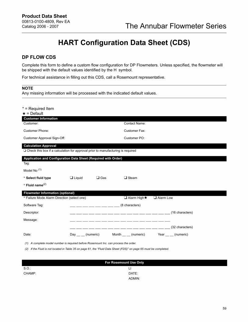
HART Configuration Data Sheet (CDS)
DP FLOW CDS
Complete this form to define a custom flow configuration for DP Flowmeters. Unless specified, the flowmeter will
be shipped with the default values identified by the H symbol.
For technical assistance in filling out this CDS, call a Rosemount representative.
NOTE
Any missing information will be processed with the indicated default values.
* = Required Item
★ = DefaultCustomer Information
Customer: Contact Name:
Customer Phone: Customer Fax:
Customer Approval Sign-Off: Customer PO:
Calculation Approval
❑ Check this box if a calculation for approval prior to manufacturing is required
Application and Configuration Data Sheet (Required with Order)
Tag:
Model No (1)
* Select fluid type ❑ Liquid ❑ Gas ❑ Steam
* Fluid name(2)
Flowmeter Information (optional)
* Failure Mode Alarm Direction (select one) ❑ Alarm High★ ❑ Alarm Low
Software Tag: ___ ___ ___ ___ ___ ___ ___ ___ (8 characters)
Descriptor: ___ ___ ___ ___ ___ ___ ___ ___ ___ ___ ___ ___ ___ ___ ___ ___ (16 characters)
Message: ___ ___ ___ ___ ___ ___ ___ ___ ___ ___ ___ ___ ___ ___ ___ ___
___ ___ ___ ___ ___ ___ ___ ___ ___ ___ ___ ___ ___ ___ ___ ___ (32 characters)
Date: Day __ __ (numeric) Month __ __ (numeric) Year __ __ (numeric)
(1) A complete model number is required before Rosemount Inc. can process the order.
(2) If the Fluid is not located in Table 35 on page 61, the “Fluid Data Sheet (FDS)” on page 65 must be completed.
For Rosemount Use Only
S.O.: LI
CHAMP: DATE:
ADMIN:
Product Data Sheet00813-0100-4809, Rev EA
Catalog 2006 - 2007The Annubar Flowmeter Series
60
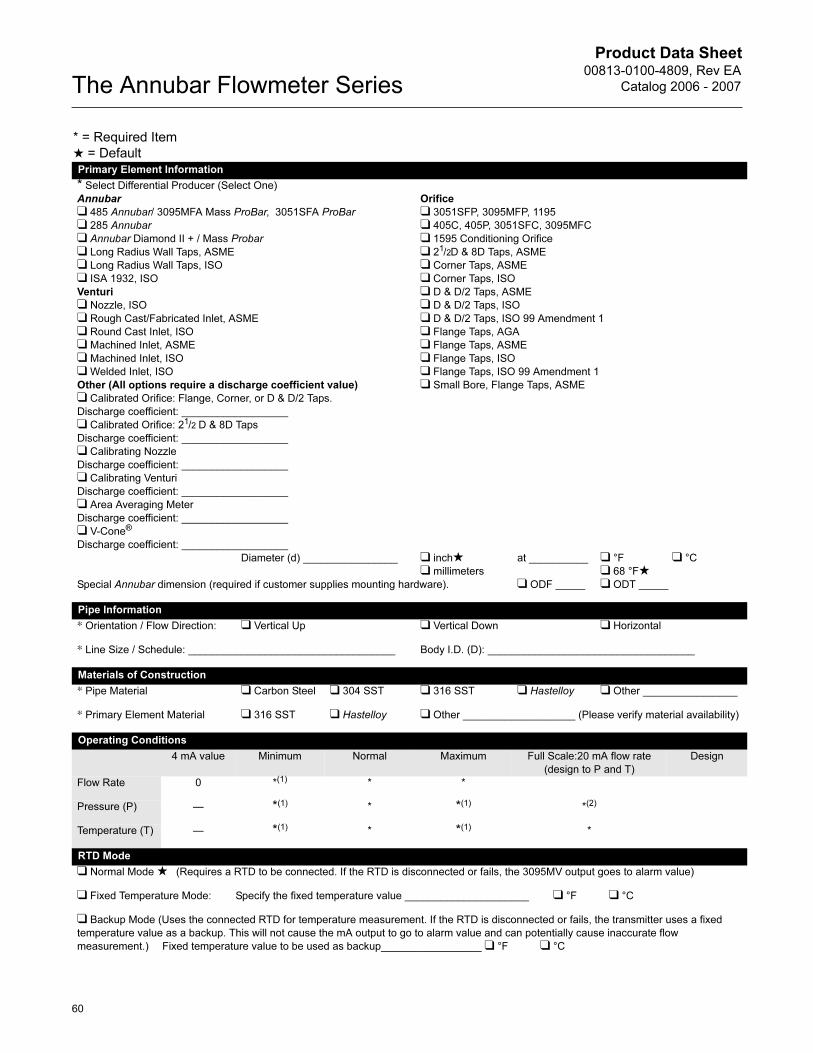
* = Required Item
★ = DefaultPrimary Element Information
* Select Differential Producer (Select One)
Annubar
❑ 485 Annubar/ 3095MFA Mass ProBar, 3051SFA ProBar
❑ 285 Annubar
❑ Annubar Diamond II + / Mass Probar
❑ Long Radius Wall Taps, ASME
❑ Long Radius Wall Taps, ISO
❑ ISA 1932, ISO
Venturi
❑ Nozzle, ISO
❑ Rough Cast/Fabricated Inlet, ASME
❑ Round Cast Inlet, ISO
❑ Machined Inlet, ASME
❑ Machined Inlet, ISO
❑ Welded Inlet, ISO
Other (All options require a discharge coefficient value)
❑ Calibrated Orifice: Flange, Corner, or D & D/2 Taps.
Discharge coefficient: __________________
❑ Calibrated Orifice: 21/2 D & 8D Taps
Discharge coefficient: __________________
❑ Calibrating Nozzle
Discharge coefficient: __________________
❑ Calibrating Venturi
Discharge coefficient: __________________
❑ Area Averaging Meter
Discharge coefficient: __________________
❑ V-Cone®
Discharge coefficient: __________________
Orifice
❑ 3051SFP, 3095MFP, 1195
❑ 405C, 405P, 3051SFC, 3095MFC
❑ 1595 Conditioning Orifice
❑ 21/2D & 8D Taps, ASME
❑ Corner Taps, ASME
❑ Corner Taps, ISO
❑ D & D/2 Taps, ASME
❑ D & D/2 Taps, ISO
❑ D & D/2 Taps, ISO 99 Amendment 1
❑ Flange Taps, AGA
❑ Flange Taps, ASME
❑ Flange Taps, ISO
❑ Flange Taps, ISO 99 Amendment 1
❑ Small Bore, Flange Taps, ASME
Diameter (d) ________________ ❑ inch★❑ millimeters
at __________ ❑ °F
❑ 68 °F★❑ °C
Special Annubar dimension (required if customer supplies mounting hardware). ❑ ODF _____ ❑ ODT _____
Pipe Information
* Orientation / Flow Direction: ❑ Vertical Up ❑ Vertical Down ❑ Horizontal
* Line Size / Schedule: ___________________________________ Body I.D. (D): ___________________________________
Materials of Construction
* Pipe Material ❑ Carbon Steel ❑ 304 SST ❑ 316 SST ❑ Hastelloy ❑ Other ________________
* Primary Element Material ❑ 316 SST ❑ Hastelloy ❑ Other ___________________ (Please verify material availability)
Operating Conditions
4 mA value Minimum Normal Maximum Full Scale:20 mA flow rate
(design to P and T)
Design
Flow Rate 0 *(1) * *
Pressure (P) — *(1) * *(1) *(2)
Temperature (T) — *(1) * *(1) *
RTD Mode
❑ Normal Mode ★ (Requires a RTD to be connected. If the RTD is disconnected or fails, the 3095MV output goes to alarm value)
❑ Fixed Temperature Mode: Specify the fixed temperature value _____________________ ❑ °F ❑ °C
❑ Backup Mode (Uses the connected RTD for temperature measurement. If the RTD is disconnected or fails, the transmitter uses a fixed
temperature value as a backup. This will not cause the mA output to go to alarm value and can potentially cause inaccurate flow
measurement.) Fixed temperature value to be used as backup_________________ ❑ °F ❑ °C
Product Data Sheet00813-0100-4809, Rev EA
Catalog 2006 - 2007
61
The Annubar Flowmeter Series
Drawing/Notes
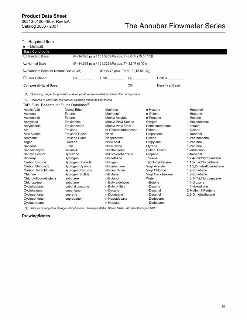
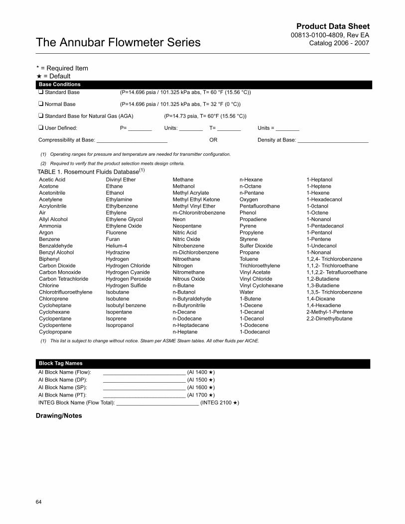
Base Conditions
❑ Standard Base (P=14.696 psia / 101.325 kPa abs, T= 60 °F (15.56 °C))
❑ Normal Base (P=14.696 psia / 101.325 kPa abs, T= 32 °F (0 °C))
❑ Standard Base for Natural Gas (AGA) (P=14.73 psia, T= 60°F (15.56 °C))
❑ User Defined: P= ________ Units: ________ T= ________ Units = ________
Compressibility at Base: ________________________ OR Density at Base: ________________________
(1) Operating ranges for pressure and temperature are needed for transmitter configuration.
(2) Required to verify that the product selection meets design criteria.
* = Required Item
★ = Default
TABLE 35. Rosemount Fluids Database(1)
Acetic Acid
Acetone
Acetonitrile
Acetylene
Acrylonitrile
Air
Allyl Alcohol
Ammonia
Argon
Benzene
Benzaldehyde
Benzyl Alcohol
Biphenyl
Carbon Dioxide
Carbon Monoxide
Carbon Tetrachloride
Chlorine
Chlorotrifluoroethylene
Chloroprene
Cycloheptane
Cyclohexane
Cyclopentane
Cyclopentene
Cyclopropane
Divinyl Ether
Ethane
Ethanol
Ethylamine
Ethylbenzene
Ethylene
Ethylene Glycol
Ethylene Oxide
Fluorene
Furan
Helium-4
Hydrazine
Hydrogen
Hydrogen Chloride
Hydrogen Cyanide
Hydrogen Peroxide
Hydrogen Sulfide
Isobutane
Isobutene
Isobutyl benzene
Isopentane
Isoprene
Isopropanol
Methane
Methanol
Methyl Acrylate
Methyl Ethyl Ketone
Methyl Vinyl Ether
m-Chloronitrobenzene
Neon
Neopentane
Nitric Acid
Nitric Oxide
Nitrobenzene
m-Dichlorobenzene
Nitroethane
Nitrogen
Nitromethane
Nitrous Oxide
n-Butane
n-Butanol
n-Butyraldehyde
n-Butyronitrile
n-Decane
n-Dodecane
n-Heptadecane
n-Heptane
n-Hexane
n-Octane
n-Pentane
Oxygen
Pentafluorothane
Phenol
Propadiene
Pyrene
Propylene
Styrene
Sulfer Dioxide
Propane
Toluene
Trichloroethylene
Vinyl Acetate
Vinyl Chloride
Vinyl Cyclohexane
Water
1-Butene
1-Decene
1-Decanal
1-Decanol
1-Dodecene
1-Dodecanol
1-Heptanol
1-Heptene
1-Hexene
1-Hexadecanol
1-0ctanol
1-Octene
1-Nonanol
1-Pentadecanol
1-Pentanol
1-Pentene
1-Undecanol
1-Nonanal
1,2,4- Trichlorobenzene
1,1,2- Trichloroethane
1,1,2,2- Tetrafluoroethane
1,2-Butadiene
1,3-Butadiene
1,3,5- Trichlorobenzene
1,4-Dioxane
1,4-Hexadiene
2-Methyl-1-Pentene
2,2-Dimethylbutane
(1) This list is subject to change without notice. Steam per ASME Steam tables. All other fluids per AlChE.
Product Data Sheet00813-0100-4809, Rev EA
Catalog 2006 - 2007The Annubar Flowmeter Series
62
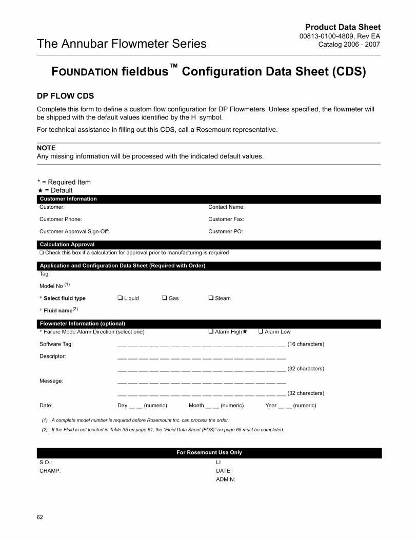
FOUNDATION fieldbus™ Configuration Data Sheet (CDS)
DP FLOW CDS
Complete this form to define a custom flow configuration for DP Flowmeters. Unless specified, the flowmeter will
be shipped with the default values identified by the H symbol.
For technical assistance in filling out this CDS, call a Rosemount representative.
NOTE
Any missing information will be processed with the indicated default values.
* = Required Item
★ = DefaultCustomer Information
Customer: Contact Name:
Customer Phone: Customer Fax:
Customer Approval Sign-Off: Customer PO:
Calculation Approval
❑ Check this box if a calculation for approval prior to manufacturing is required
Application and Configuration Data Sheet (Required with Order)
Tag:
Model No (1)
* Select fluid type ❑ Liquid ❑ Gas ❑ Steam
* Fluid name(2)
Flowmeter Information (optional)
* Failure Mode Alarm Direction (select one) ❑ Alarm High★ ❑ Alarm Low
Software Tag: ___ ___ ___ ___ ___ ___ ___ ___ ___ ___ ___ ___ ___ ___ ___ ___ (16 characters)
Descriptor: ___ ___ ___ ___ ___ ___ ___ ___ ___ ___ ___ ___ ___ ___ ___ ___
___ ___ ___ ___ ___ ___ ___ ___ ___ ___ ___ ___ ___ ___ ___ ___ (32 characters)
Message: ___ ___ ___ ___ ___ ___ ___ ___ ___ ___ ___ ___ ___ ___ ___ ___
___ ___ ___ ___ ___ ___ ___ ___ ___ ___ ___ ___ ___ ___ ___ ___ (32 characters)
Date: Day __ __ (numeric) Month __ __ (numeric) Year __ __ (numeric)
(1) A complete model number is required before Rosemount Inc. can process the order.
(2) If the Fluid is not located in Table 35 on page 61, the “Fluid Data Sheet (FDS)” on page 65 must be completed.
For Rosemount Use Only
S.O.: LI
CHAMP: DATE:
ADMIN:
Product Data Sheet00813-0100-4809, Rev EA
Catalog 2006 - 2007
63
The Annubar Flowmeter Series
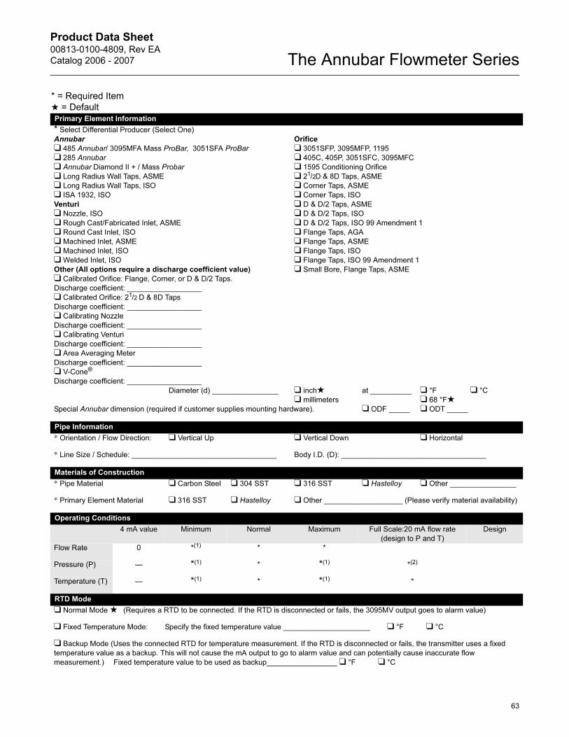
* = Required Item
★ = DefaultPrimary Element Information
* Select Differential Producer (Select One)
Annubar
❑ 485 Annubar/ 3095MFA Mass ProBar, 3051SFA ProBar
❑ 285 Annubar
❑ Annubar Diamond II + / Mass Probar
❑ Long Radius Wall Taps, ASME
❑ Long Radius Wall Taps, ISO
❑ ISA 1932, ISO
Venturi
❑ Nozzle, ISO
❑ Rough Cast/Fabricated Inlet, ASME
❑ Round Cast Inlet, ISO
❑ Machined Inlet, ASME
❑ Machined Inlet, ISO
❑ Welded Inlet, ISO
Other (All options require a discharge coefficient value)
❑ Calibrated Orifice: Flange, Corner, or D & D/2 Taps.
Discharge coefficient: __________________
❑ Calibrated Orifice: 21/2 D & 8D Taps
Discharge coefficient: __________________
❑ Calibrating Nozzle
Discharge coefficient: __________________
❑ Calibrating Venturi
Discharge coefficient: __________________
❑ Area Averaging Meter
Discharge coefficient: __________________
❑ V-Cone®
Discharge coefficient: __________________
Orifice
❑ 3051SFP, 3095MFP, 1195
❑ 405C, 405P, 3051SFC, 3095MFC
❑ 1595 Conditioning Orifice
❑ 21/2D & 8D Taps, ASME
❑ Corner Taps, ASME
❑ Corner Taps, ISO
❑ D & D/2 Taps, ASME
❑ D & D/2 Taps, ISO
❑ D & D/2 Taps, ISO 99 Amendment 1
❑ Flange Taps, AGA
❑ Flange Taps, ASME
❑ Flange Taps, ISO
❑ Flange Taps, ISO 99 Amendment 1
❑ Small Bore, Flange Taps, ASME
Diameter (d) ________________ ❑ inch★❑ millimeters
at __________ ❑ °F
❑ 68 °F★❑ °C
Special Annubar dimension (required if customer supplies mounting hardware). ❑ ODF _____ ❑ ODT _____
Pipe Information
* Orientation / Flow Direction: ❑ Vertical Up ❑ Vertical Down ❑ Horizontal
* Line Size / Schedule: ___________________________________ Body I.D. (D): ___________________________________
Materials of Construction
* Pipe Material ❑ Carbon Steel ❑ 304 SST ❑ 316 SST ❑ Hastelloy ❑ Other ________________
* Primary Element Material ❑ 316 SST ❑ Hastelloy ❑ Other ___________________ (Please verify material availability)
Operating Conditions
4 mA value Minimum Normal Maximum Full Scale:20 mA flow rate
(design to P and T)
Design
Flow Rate 0 *(1) * *
Pressure (P) — *(1) * *(1) *(2)
Temperature (T) — *(1) * *(1) *
RTD Mode
❑ Normal Mode ★ (Requires a RTD to be connected. If the RTD is disconnected or fails, the 3095MV output goes to alarm value)
❑ Fixed Temperature Mode: Specify the fixed temperature value _____________________ ❑ °F ❑ °C
❑ Backup Mode (Uses the connected RTD for temperature measurement. If the RTD is disconnected or fails, the transmitter uses a fixed
temperature value as a backup. This will not cause the mA output to go to alarm value and can potentially cause inaccurate flow
measurement.) Fixed temperature value to be used as backup_________________ ❑ °F ❑ °C
Product Data Sheet00813-0100-4809, Rev EA
Catalog 2006 - 2007The Annubar Flowmeter Series
64
Drawing/Notes
Base Conditions
❑ Standard Base (P=14.696 psia / 101.325 kPa abs, T= 60 °F (15.56 °C))
❑ Normal Base (P=14.696 psia / 101.325 kPa abs, T= 32 °F (0 °C))
❑ Standard Base for Natural Gas (AGA) (P=14.73 psia, T= 60°F (15.56 °C))
❑ User Defined: P= ________ Units: ________ T= ________ Units = ________
Compressibility at Base: ________________________ OR Density at Base: ________________________
(1) Operating ranges for pressure and temperature are needed for transmitter configuration.
(2) Required to verify that the product selection meets design criteria.
* = Required Item
★ = Default
TABLE 1. Rosemount Fluids Database(1)
Acetic Acid
Acetone
Acetonitrile
Acetylene
Acrylonitrile
Air
Allyl Alcohol
Ammonia
Argon
Benzene
Benzaldehyde
Benzyl Alcohol
Biphenyl
Carbon Dioxide
Carbon Monoxide
Carbon Tetrachloride
Chlorine
Chlorotrifluoroethylene
Chloroprene
Cycloheptane
Cyclohexane
Cyclopentane
Cyclopentene
Cyclopropane
Divinyl Ether
Ethane
Ethanol
Ethylamine
Ethylbenzene
Ethylene
Ethylene Glycol
Ethylene Oxide
Fluorene
Furan
Helium-4
Hydrazine
Hydrogen
Hydrogen Chloride
Hydrogen Cyanide
Hydrogen Peroxide
Hydrogen Sulfide
Isobutane
Isobutene
Isobutyl benzene
Isopentane
Isoprene
Isopropanol
Methane
Methanol
Methyl Acrylate
Methyl Ethyl Ketone
Methyl Vinyl Ether
m-Chloronitrobenzene
Neon
Neopentane
Nitric Acid
Nitric Oxide
Nitrobenzene
m-Dichlorobenzene
Nitroethane
Nitrogen
Nitromethane
Nitrous Oxide
n-Butane
n-Butanol
n-Butyraldehyde
n-Butyronitrile
n-Decane
n-Dodecane
n-Heptadecane
n-Heptane
n-Hexane
n-Octane
n-Pentane
Oxygen
Pentafluorothane
Phenol
Propadiene
Pyrene
Propylene
Styrene
Sulfer Dioxide
Propane
Toluene
Trichloroethylene
Vinyl Acetate
Vinyl Chloride
Vinyl Cyclohexane
Water
1-Butene
1-Decene
1-Decanal
1-Decanol
1-Dodecene
1-Dodecanol
1-Heptanol
1-Heptene
1-Hexene
1-Hexadecanol
1-0ctanol
1-Octene
1-Nonanol
1-Pentadecanol
1-Pentanol
1-Pentene
1-Undecanol
1-Nonanal
1,2,4- Trichlorobenzene
1,1,2- Trichloroethane
1,1,2,2- Tetrafluoroethane
1,2-Butadiene
1,3-Butadiene
1,3,5- Trichlorobenzene
1,4-Dioxane
1,4-Hexadiene
2-Methyl-1-Pentene
2,2-Dimethylbutane
(1) This list is subject to change without notice. Steam per ASME Steam tables. All other fluids per AlChE.
Block Tag Names
AI Block Name (Flow): ____________________________ (AI 1400 ★)
AI Block Name (DP): ____________________________ (AI 1500 ★)
AI Block Name (SP): ____________________________ (AI 1600 ★)
AI Block Name (PT): ____________________________ (AI 1700 ★)
INTEG Block Name (Flow Total): ____________________________ (INTEG 2100 ★)
Product Data Sheet00813-0100-4809, Rev EA
Catalog 2006 - 2007
65
The Annubar Flowmeter Series
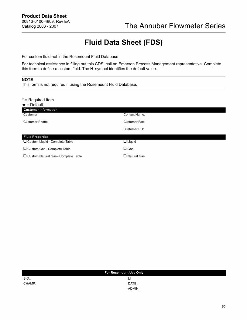
Fluid Data Sheet (FDS)
For custom fluid not in the Rosemount Fluid Database
For technical assistance in filling out this CDS, call an Emerson Process Management representative. Complete
this form to define a custom fluid. The H symbol identifies the default value.
NOTE
This form is not required if using the Rosemount Fluid Database.
* = Required Item
★ = DefaultCustomer Information
Customer: Contact Name:
Customer Phone: Customer Fax:
Customer PO:
Fluid Properties
❑ Custom Liquid– Complete Table ❑ Liquid
❑ Custom Gas– Complete Table ❑ Gas
❑ Custom Natural Gas– Complete Table ❑ Natural Gas
For Rosemount Use Only
S.O.: LI
CHAMP: DATE:
ADMIN:

Product Data Sheet00813-0100-4809, Rev EA
Catalog 2006 - 2007The Annubar Flowmeter Series
66
TABLE 36. Custom Liquid Worksheet
* = Required Item
★ = DefaultMass Liquid Density and Viscosity Information
1. Fill in the following operating temperatures
a) _________________________ min
b) _________________________ [1/3 (max - min))] + min
c) _________________________ [2/3 (max - min))] + min
d) _________________________ max
2. Transfer the values from the above section to the numbered lines below.
3. Check one Density box, then enter the values for each temperature and the standard density.
4. Check one Viscosity box, then enter values for each temperature. (At least one viscosity value is required).
Density
❑ Density in lbs/CuFt
❑ Density in kg/CuM
Viscosity
❑ Viscosity in centipoise
❑ Viscosity in lbs/ft sec
❑ Viscosity in pascal sec
Temperature Temperature
a) _____________ min a) _____________ min.
b) _____________ [1/3 (max - min))] + min b) _____________ [1/3 (max - min))] + min
c) _____________ [2/3 (max - min))] + min c) _____________ [2/3 (max - min))] + min
d) _____________ max d) _____________ max
Base density: __________________________________________________________
(at base reference conditions specified)
Volumetric Liquid Density and Viscosity Information
* Density at Flow: _________________________________________________ Units: ❑ lb/ft3 ❑ Kg/m3 ❑ Other:
OR
Specific Gravity at Flow: ____________________________________________
* Viscosity at Flow: ________________________________________________ Units: ❑ Centipoise ❑ Other:
Product Data Sheet00813-0100-4809, Rev EA
Catalog 2006 - 2007
67
The Annubar Flowmeter Series
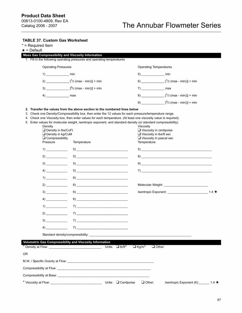
TABLE 37. Custom Gas Worksheet
* = Required Item
★ = DefaultMass Gas Compressibility and Viscosity Information
1. Fill in the following operating pressures and operating temperatures
Operating Pressures Operating Temperatures
1) _____________ min 5) _____________ min
2) _____________ [1/3 (max - min))] + min 6) _____________ [1/2 (max - min))] + min
3) _____________ [2/3 (max - min))] + min 7) _____________ max
4) _____________ max 8) _____________ [1/3 (max - min))] + min
9) _____________ [2/3 (max - min))] + min
2. Transfer the values from the above section to the numbered lines below
3. Check one Density/Compressibility box, then enter the 12 values for each pressure/temperature range.
4. Check one Viscosity box, then enter values for each temperature. (At least one viscosity value is required).
5. Enter values for molecular weight, isentropic exponent, and standard density (or standard compressibility).
Density
❑ Density in lbs/CuFt
❑ Density in kg/CuM
❑ Compressibility
Viscosity
❑ Viscosity in centipoise
❑ Viscosity in lbs/ft sec
❑ Viscosity in pascal sec
Pressure Temperature Temperature
1) ____________ 5) _____________________________ 5) ________________________________________
2) ____________ 5) _____________________________ 8) ________________________________________
3) ____________ 5) _____________________________ 9) ________________________________________
4) ____________ 5) _____________________________ 7) ________________________________________
1) ____________ 6) _____________________________
2) ____________ 6) _____________________________ Molecular Weight: _________________________
3) ____________ 6) _____________________________ Isentropic Exponent: _______________________ 1.4 ★
4) ____________ 6) _____________________________
1) ____________ 7) _____________________________
2) ____________ 7) _____________________________
3) ____________ 7) _____________________________
4) ____________ 7) _____________________________
Standard density/compressibility: __________________________________________________________
Volumetric Gas Compressibility and Viscosity Information
* Density at Flow: ______________________________ Units: ❑ lb/ft3 ❑ Kg/m3 ❑ Other:
OR
M.W. / Specific Gravity at Flow: _________________________________________________
Compressibility at Flow: _____________________________________________________
Compressibility at Base: ____________________________________________________
* Viscosity at Flow: _____________________________ Units: ❑ Centipoise ❑ Other: Isentropic Exponent (K):______ 1.4 ★
Product Data Sheet00813-0100-4809, Rev EA
Catalog 2006 - 2007The Annubar Flowmeter Series
68
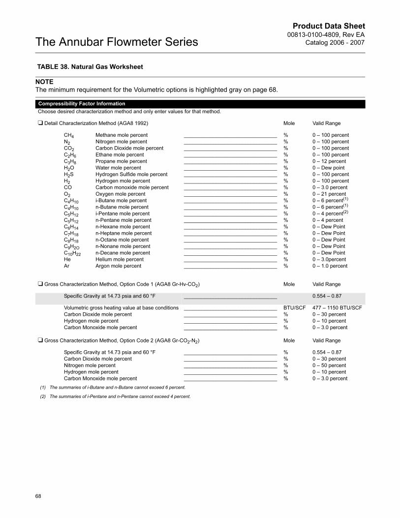
TABLE 38. Natural Gas Worksheet
NOTE
The minimum requirement for the Volumetric options is highlighted gray on page 68.
Compressibility Factor Information
Choose desired characterization method and only enter values for that method.
❑ Detail Characterization Method (AGA8 1992) Mole Valid Range
CH4
N2
CO2
C2H6
C3H8
H2O
H2S
H2
CO
O2
C4H10
C4H10
C5H12
C5H12
C6H14
C7H18
C8H18
C9H2O
C10H22
He
Ar
Methane mole percent
Nitrogen mole percent
Carbon Dioxide mole percent
Ethane mole percent
Propane mole percent
Water mole percent
Hydrogen Sulfide mole percent
Hydrogen mole percent
Carbon monoxide mole percent
Oxygen mole percent
i-Butane mole percent
n-Butane mole percent
i-Pentane mole percent
n-Pentane mole percent
n-Hexane mole percent
n-Heptane mole percent
n-Octane mole percent
n-Nonane mole percent
n-Decane mole percent
Helium mole percent
Argon mole percent
________________________________
________________________________
________________________________
________________________________
________________________________
________________________________
________________________________
________________________________
________________________________
________________________________
________________________________
________________________________
________________________________
________________________________
________________________________
________________________________
________________________________
________________________________
________________________________
________________________________
________________________________
%
%
%
%
%
%
%
%
%
%
%
%
%
%
%
%
%
%
%
%
%
0 – 100 percent
0 – 100 percent
0 – 100 percent
0 – 100 percent
0 – 12 percent
0 – Dew point
0 – 100 percent
0 – 100 percent
0 – 3.0 percent
0 – 21 percent
0 – 6 percent(1)
0 – 6 percent(1)
0 – 4 percent(2)
0 – 4 percent
0 – Dew Point
0 – Dew Point
0 – Dew Point
0 – Dew Point
0 – Dew Point
0 – 3.0percent
0 – 1.0 percent
(1) The summaries of i-Butane and n-Butane cannot exceed 6 percent.
(2) The summaries of i-Pentane and n-Pentane cannot exceed 4 percent.
❑ Gross Characterization Method, Option Code 1 (AGA8 Gr-Hv-CO2) Mole Valid Range
Specific Gravity at 14.73 psia and 60 °F ________________________________ 0.554 – 0.87
Volumetric gross heating value at base conditions
Carbon Dioxide mole percent
Hydrogen mole percent
Carbon Monoxide mole percent
________________________________
________________________________
________________________________
________________________________
BTU/SCF
%
%
%
477 – 1150 BTU/SCF
0 – 30 percent
0 – 10 percent
0 – 3.0 percent
❑ Gross Characterization Method, Option Code 2 (AGA8 Gr-CO2-N2) Mole Valid Range
Specific Gravity at 14.73 psia and 60 °F
Carbon Dioxide mole percent
Nitrogen mole percent
Hydrogen mole percent
Carbon Monoxide mole percent
________________________________
________________________________
________________________________
________________________________
________________________________
%
%
%
%
%
0.554 – 0.87
0 – 30 percent
0 – 50 percent
0 – 10 percent
0 – 3.0 percent

Product Data Sheet00813-0100-4809, Rev EA
Catalog 2006 - 2007
69
The Annubar Flowmeter Series
Rosemount, the Rosemount logotype, ProBar, Mass ProBar and Annubar are registered trademarks of Rosemount Inc. MultiVariable (MV), Coplanar, SuperModules, and Tri-Loop are trademarks of Rosemount Inc. Inconel is a trademark of International Nickel Co. Hastelloy is a registered trademark of Haynes International. HART is a registered trademark of the HART Communication Foundation. FOUNDATION is a trademark of the Fieldbus Foundation. All other marks are the property of their respective owners.
Emerson Process Management
© 2006 Rosemount Inc. All rights reserved.
¢00813-0100-4809M¤
Emerson Process Management Heath PlaceBognor RegisWest Sussex PO22 9SHEnglandT 44 (0) 1243 863121F 44 (0) 1243 867554
Emerson Process Management Asia Pacific Private Limited1 Pandan CrescentSingapore 128461T (65) 6777 8211F (65) 6777 [email protected]
Rosemount Inc.8200 Market BoulevardChanhassen, MN 55317 USAT (U.S.) 1-800-999-9307T (International) (952) 906-8888F (952) 949-7001
www.rosemount.com
Product Data Sheet00813-0100-4809, Rev EA
Catalog 2006 - 2007The Annubar Flowmeter Series