rosemount 3100 series ultrasonic level transmitters · catalog 2008 - 2009 rosemount 3100 series...
TRANSCRIPT
Product Data Sheet00813-0100-4840, Rev. AB
Catalog 2008 - 2009 Rosemount 3100 Series
Rosemount 3100 Series
Ultrasonic Level Transmitters
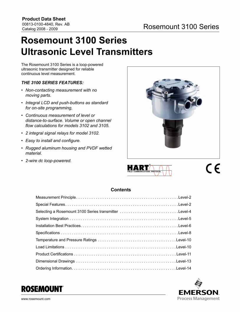
The Rosemount 3100 Series is a loop-powered ultrasonic transmitter designed for reliable continuous level measurement.THE 3100 SERIES FEATURES:
• Non-contacting measurement with no
moving parts.
• Integral LCD and push-buttons as standard
for on-site programming,
• Continuous measurement of level or
distance-to-surface. Volume or open channel
flow calculations for models 3102 and 3105.
• 2 integral signal relays for model 3102.
• Easy to install and configure.
• Rugged aluminum housing and PVDF wetted
material.
• 2-wire dc loop-powered.
Contents
Measurement Principle . . . . . . . . . . . . . . . . . . . . . . . . . . . . . . . . . . . . . . . . . . . . . . . Level-2
Special Features. . . . . . . . . . . . . . . . . . . . . . . . . . . . . . . . . . . . . . . . . . . . . . . . . . . . Level-2
Selecting a Rosemount 3100 Series transmitter . . . . . . . . . . . . . . . . . . . . . . . . . . . Level-4
www.ros
System Integration . . . . . . . . . . . . . . . . . . . . . . . . . . . . . . . . . . . . . . . . . . . . . . . . . . Level-5
Installation Best Practices. . . . . . . . . . . . . . . . . . . . . . . . . . . . . . . . . . . . . . . . . . . . . Level-6
Specifications . . . . . . . . . . . . . . . . . . . . . . . . . . . . . . . . . . . . . . . . . . . . . . . . . . . . . . Level-8
Temperature and Pressure Ratings . . . . . . . . . . . . . . . . . . . . . . . . . . . . . . . . . . . . Level-10
Load Limitations . . . . . . . . . . . . . . . . . . . . . . . . . . . . . . . . . . . . . . . . . . . . . . . . . . . Level-10
Product Certifications . . . . . . . . . . . . . . . . . . . . . . . . . . . . . . . . . . . . . . . . . . . . . . . Level-11
Dimensional Drawings . . . . . . . . . . . . . . . . . . . . . . . . . . . . . . . . . . . . . . . . . . . . . . Level-13
Ordering Information. . . . . . . . . . . . . . . . . . . . . . . . . . . . . . . . . . . . . . . . . . . . . . . . Level-14
emount.com
Product Data Sheet00813-0100-4840, Rev. AB
Catalog 2008 - 2009Rosemount 3100 Series
Reliability in a Universal Package
The Rosemount 3100 Series is a liquid level transmitter based on ultrasonic technology making it suitable for many liquid applications.
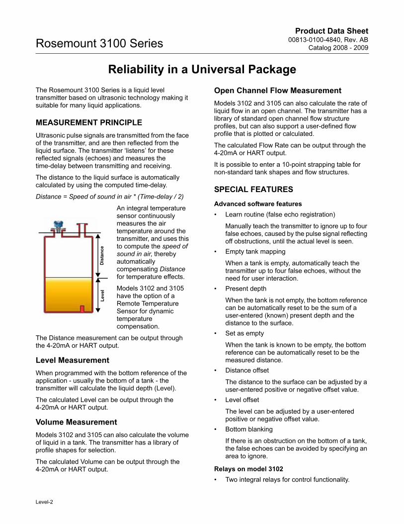
MEASUREMENT PRINCIPLE
Ultrasonic pulse signals are transmitted from the face of the transmitter, and are then reflected from the liquid surface. The transmitter ‘listens’ for these reflected signals (echoes) and measures the time-delay between transmitting and receiving.
The distance to the liquid surface is automatically calculated by using the computed time-delay.
Distance = Speed of sound in air * (Time-delay / 2)
An integral temperature sensor continuously measures the air temperature around the transmitter, and uses this to compute the speed of sound in air, thereby automatically compensating Distance for temperature effects.
Models 3102 and 3105 have the option of a Remote Temperature Sensor for dynamic temperature compensation.
The Distance measurement can be output through the 4-20mA or HART output.
Level Measurement
When programmed with the bottom reference of the application - usually the bottom of a tank - the transmitter will calculate the liquid depth (Level).
The calculated Level can be output through the 4-20mA or HART output.
Volume Measurement
Models 3102 and 3105 can also calculate the volume of liquid in a tank. The transmitter has a library of profile shapes for selection.
The calculated Volume can be output through the 4-20mA or HART output.
Open Channel Flow Measurement
Models 3102 and 3105 can also calculate the rate of liquid flow in an open channel. The transmitter has a library of standard open channel flow structure profiles, but can also support a user-defined flow profile that is plotted or calculated.
The calculated Flow Rate can be output through the 4-20mA or HART output.
It is possible to enter a 10-point strapping table for non-standard tank shapes and flow structures.
SPECIAL FEATURES
Advanced software features
• Learn routine (false echo registration)
Manually teach the transmitter to ignore up to four false echoes, caused by the pulse signal reflecting off obstructions, until the actual level is seen.
• Empty tank mapping
When a tank is empty, automatically teach the transmitter up to four false echoes, without the need for user interaction.
• Present depth
When the tank is not empty, the bottom reference can be automatically reset to be the sum of a user-entered (known) present depth and the distance to the surface.
• Set as empty
When the tank is known to be empty, the bottom reference can be automatically reset to be the measured distance.
• Distance offset
The distance to the surface can be adjusted by a user-entered positive or negative offset value.
• Level offset
The level can be adjusted by a user-entered positive or negative offset value.
• Bottom blanking
If there is an obstruction on the bottom of a tank, the false echoes can be avoided by specifying an area to ignore.
Relays on model 3102
• Two integral relays for control functionality.
Distance
Level
Level-2
Product Data Sheet00813-0100-4840, Rev. AB
Catalog 2008 - 2009 Rosemount 3100 Series
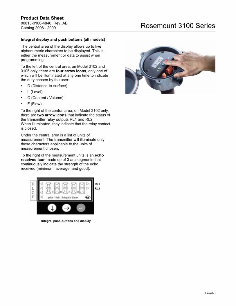
Integral display and push buttons (all models)
The central area of the display allows up to five alphanumeric characters to be displayed. This is either the measurement or data to assist when programming.
To the left of the central area, on Model 3102 and 3105 only, there are four arrow icons, only one of which will be illuminated at any one time to indicate the duty chosen by the user:
• D (Distance-to-surface)
• L (Level)
• C (Content / Volume)
• F (Flow)
To the right of the central area, on Model 3102 only, there are two arrow icons that indicate the status of the transmitter relay outputs RL1 and RL2.When illuminated, they indicate that the relay contact is closed.
Under the central area is a list of units of measurement. The transmitter will illuminate only those characters applicable to the units of measurement chosen.
To the right of the measurement units is an echo received icon made up of 3 arc segments that continuously indicate the strength of the echo received (minimum, average, and good).
Integral push-buttons and display
RL1
RL2
Level-3
Product Data Sheet00813-0100-4840, Rev. AB
Catalog 2008 - 2009Rosemount 3100 Series
Selecting a Rosemount 3100 Series transmitter
Overview of models
Choose model 3101 for simple level or distance measurements over a range of 1 - 26 ft (0.3 - 8 m), and a 4-20mA signal output.
Choose model 3102, with 2 integral relays, for level or distance measurements over a range of 1 - 36 ft (0.3 - 11 m). Also features volume and open channel flow calculations, and a 4-20mA / HART output.
Choose the Intrinsically Safe certified model 3105 for level or distance measurements over a range of 1 - 36 ft (0.3 - 11 m) in hazardous areas. Also features volume and open channel flow calculations, and a 4-20mA / HART output.
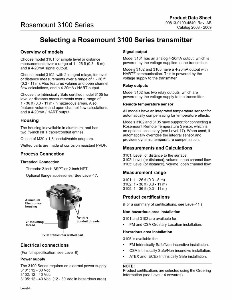
Housing
The housing is available in aluminum, and hastwo 1/2-inch NPT cable/conduit entries.
Option of M20 x 1.5 conduit/cable adaptors.
Wetted parts are made of corrosion resistant PVDF.
Process Connection
Threaded Connection
Threads: 2-inch BSPT or 2-inch NPT.
Optional flange accessories: See Level-17.
Electrical connections
(For full specification, see Level-8)
Power supply
The 3100 Series requires an external power supply:3101: 12 - 30 Vdc 3102: 12 - 40 Vdc 3105: 12 - 40 Vdc, (12 - 30 Vdc in hazardous area).
Signal output
Model 3101 has an analog 4-20mA output, which is powered by the voltage supplied to the transmitter.
Models 3102 and 3105 have a 4-20mA output with HART® communication. This is powered by the voltage supply to the transmitter.
Relay outputs
Model 3102 has two relay outputs, which are powered by the voltage supply to the transmitter.
Remote temperature sensor
All models have an integrated temperature sensor for automatically compensating for temperature effects.
Models 3102 and 3105 have support for connecting a Rosemount Remote Temperature Sensor, which is an optional accessory (see Level-17). When used, it automatically overrides the integral sensor and provides dynamic temperature compensation.
Measurements and Calculations
3101: Level, or distance to the surface.3102: Level (or distance), volume, open channel flow.3105: Level (or distance), volume, open channel flow.
Measurement range
3101: 1 - 26 ft (0.3 - 8 m)3102: 1 - 36 ft (0.3 - 11 m)3105: 1 - 36 ft (0.3 - 11 m)
Product certifications
(For a summary of certifications, see Level-11.)
Non-hazardous area installation
3101 and 3102 are available for:
• FM and CSA Ordinary Location installation.
Hazardous area installation
3105 is available for:
• FM Intrinsically Safe/Non-incendive installation.
• CSA Intrinsically Safe/Non-incendive installation.
• ATEX and IECEx Intrinsically Safe installation.
NOTE:Product certifications are selected using the Ordering Information (see Level-14 onwards).
1/2” NPT conduit threads
PVDF transmitter wetted part
2” mountingthread
AluminumElectronics housing
Level-4
Product Data Sheet00813-0100-4840, Rev. AB
Catalog 2008 - 2009 Rosemount 3100 Series
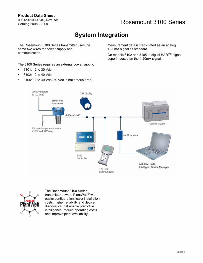
System Integration
The Rosemount 3100 Series transmitter uses the same two wires for power supply and communication.
The 3100 Series requires an external power supply:
• 3101: 12 to 30 Vdc
• 3102: 12 to 40 Vdc
• 3105: 12 to 40 Vdc (30 Vdc in hazardous area).
Measurement data is transmitted as an analog 4-20mA signal as standard.
On models 3102 and 3105, a digital HART® signal superimposed on the 4-20mA signal.
The Rosemount 3100 Series transmitter powers PlantWeb® with easier configuration, lower installation costs, higher reliability and device diagnostics that enable predictive intelligence, reduce operating costs and improve plant availability.
Level-5
Product Data Sheet00813-0100-4840, Rev. AB
Catalog 2008 - 2009Rosemount 3100 Series
Installation Best Practices
Correct location of the transmitter is essential for the reliable operation of any ultrasonic level measurement system.
NOTE:The Rosemount 3100 Series is designed to be mounted in a non-metallic fitting or flange. Please check optional PVC flange accessories on Level-17.
Mounting considerations
a) The transmitter should be mounted above the liquid surface using the 2-inch thread provided. To facilitate mounting, optional flanges are available as an accessory - see Level-17.
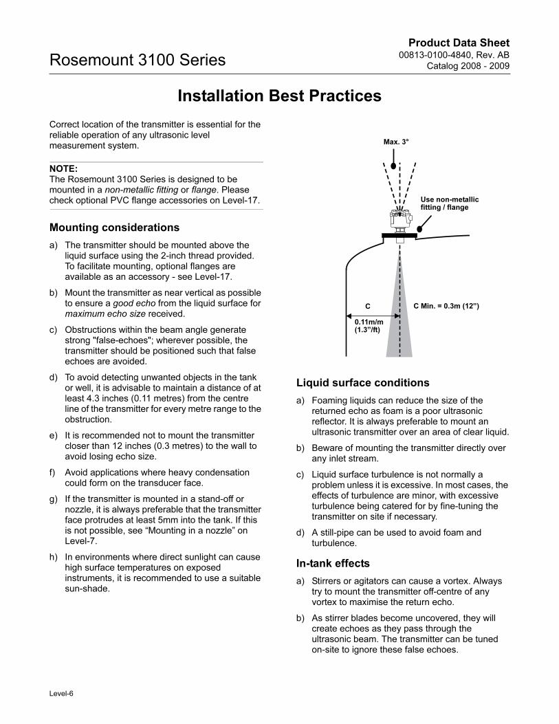
b) Mount the transmitter as near vertical as possible to ensure a good echo from the liquid surface for maximum echo size received.
c) Obstructions within the beam angle generate strong "false-echoes"; wherever possible, the transmitter should be positioned such that false echoes are avoided.
d) To avoid detecting unwanted objects in the tank or well, it is advisable to maintain a distance of at least 4.3 inches (0.11 metres) from the centre line of the transmitter for every metre range to the obstruction.
e) It is recommended not to mount the transmitter closer than 12 inches (0.3 metres) to the wall to avoid losing echo size.
f) Avoid applications where heavy condensation could form on the transducer face.
g) If the transmitter is mounted in a stand-off or nozzle, it is always preferable that the transmitter face protrudes at least 5mm into the tank. If this is not possible, see “Mounting in a nozzle” on Level-7.
h) In environments where direct sunlight can cause high surface temperatures on exposed instruments, it is recommended to use a suitable sun-shade.
Liquid surface conditions
a) Foaming liquids can reduce the size of the returned echo as foam is a poor ultrasonic reflector. It is always preferable to mount an ultrasonic transmitter over an area of clear liquid.
b) Beware of mounting the transmitter directly over any inlet stream.
c) Liquid surface turbulence is not normally a problem unless it is excessive. In most cases, the effects of turbulence are minor, with excessive turbulence being catered for by fine-tuning the transmitter on site if necessary.
d) A still-pipe can be used to avoid foam and turbulence.
In-tank effects
a) Stirrers or agitators can cause a vortex. Always try to mount the transmitter off-centre of any vortex to maximise the return echo.
b) As stirrer blades become uncovered, they will create echoes as they pass through the ultrasonic beam. The transmitter can be tuned on-site to ignore these false echoes.
Max. 3°
C
0.11m/m(1.3”/ft)
C Min. = 0.3m (12”)
Use non-metallic fitting / flange
Level-6
Product Data Sheet00813-0100-4840, Rev. AB
Catalog 2008 - 2009 Rosemount 3100 Series
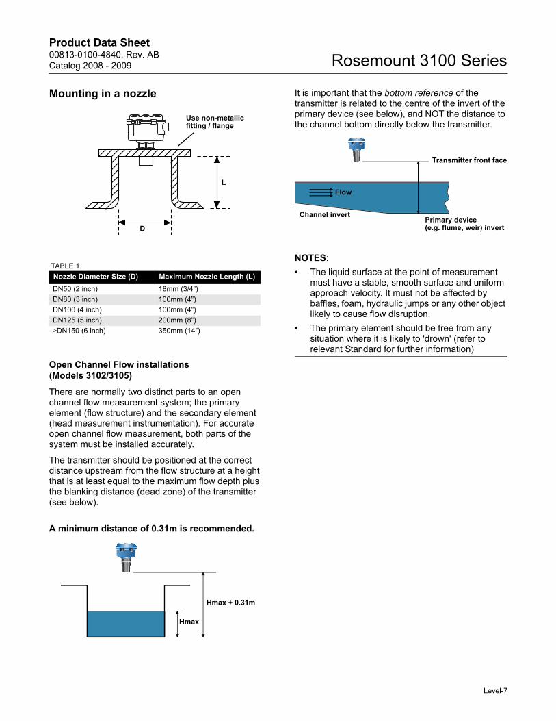
Mounting in a nozzle
TABLE 1.
Open Channel Flow installations
(Models 3102/3105)
There are normally two distinct parts to an open channel flow measurement system; the primary element (flow structure) and the secondary element (head measurement instrumentation). For accurate open channel flow measurement, both parts of the system must be installed accurately.
The transmitter should be positioned at the correct distance upstream from the flow structure at a height that is at least equal to the maximum flow depth plus the blanking distance (dead zone) of the transmitter (see below).
A minimum distance of 0.31m is recommended.
It is important that the bottom reference of the transmitter is related to the centre of the invert of the primary device (see below), and NOT the distance to the channel bottom directly below the transmitter.
NOTES:
• The liquid surface at the point of measurement must have a stable, smooth surface and uniform approach velocity. It must not be affected by baffles, foam, hydraulic jumps or any other object likely to cause flow disruption.
• The primary element should be free from any situation where it is likely to 'drown' (refer to relevant Standard for further information)
Nozzle Diameter Size (D) Maximum Nozzle Length (L)
DN50 (2 inch) 18mm (3/4”)
DN80 (3 inch) 100mm (4”)
DN100 (4 inch) 100mm (4”)
DN125 (5 inch) 200mm (8”)
≥DN150 (6 inch) 350mm (14”)
L
D
Use non-metallic fitting / flange
Hmax + 0.31m
Hmax
Transmitter front face
Flow
Primary device(e.g. flume, weir) invert
Channel invert
Level-7
Product Data Sheet00813-0100-4840, Rev. AB
Catalog 2008 - 2009Rosemount 3100 Series
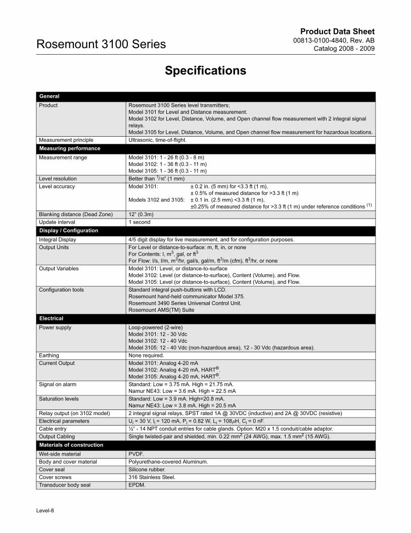
Specifications
General
Product Rosemount 3100 Series level transmitters;
Model 3101 for Level and Distance measurement.
Model 3102 for Level, Distance, Volume, and Open channel flow measurement with 2 integral signal
relays.
Model 3105 for Level, Distance, Volume, and Open channel flow measurement for hazardous locations.
Measurement principle Ultrasonic, time-of-flight.
Measuring performance
Measurement range Model 3101: 1 - 26 ft (0.3 - 8 m)
Model 3102: 1 - 36 ft (0.3 - 11 m)
Model 3105: 1 - 36 ft (0.3 - 11 m)
Level resolution Better than 1/16” (1 mm)
Level accuracy Model 3101: ± 0.2 in. (5 mm) for <3.3 ft (1 m),
± 0.5% of measured distance for >3.3 ft (1 m)
Models 3102 and 3105: ± 0.1 in. (2.5 mm) <3.3 ft (1 m),
±0.25% of measured distance for >3.3 ft (1 m) under reference conditions (1)
Blanking distance (Dead Zone) 12” (0.3m)
Update interval 1 second
Display / Configuration
Integral Display 4/5 digit display for live measurement, and for configuration purposes.
Output Units For Level or distance-to-surface: m, ft, in, or none
For Contents: l, m3, gal, or ft3
For Flow: l/s, l/m, m3/hr, gal/s, gal/m, ft3/m (cfm), ft3/hr, or none
Output Variables Model 3101: Level, or distance-to-surface
Model 3102: Level (or distance-to-surface), Content (Volume), and Flow.
Model 3105: Level (or distance-to-surface), Content (Volume), and Flow.
Configuration tools Standard integral push-buttons with LCD.
Rosemount hand-held communicator Model 375.
Rosemount 3490 Series Universal Control Unit.
Rosemount AMS(TM) Suite
Electrical
Power supply Loop-powered (2-wire)
Model 3101: 12 - 30 Vdc
Model 3102: 12 - 40 Vdc
Model 3105: 12 - 40 Vdc (non-hazardous area), 12 - 30 Vdc (hazardous area).
Earthing None required.
Current Output Model 3101: Analog 4-20 mA
Model 3102: Analog 4-20 mA, HART®.
Model 3105: Analog 4-20 mA, HART®.
Signal on alarm Standard: Low = 3.75 mA. High = 21.75 mA.
Namur NE43: Low = 3.6 mA. High = 22.5 mA
Saturation levels Standard: Low = 3.9 mA. High=20.8 mA.
Namur NE43: Low = 3.8 mA. High = 20.5 mA
Relay output (on 3102 model) 2 integral signal relays, SPST rated 1A @ 30VDC (inductive) and 2A @ 30VDC (resistive)
Electrical parameters Ui = 30 V, li = 120 mA, Pi = 0.82 W, Li = 108µH, Ci = 0 nF.
Cable entry ½” - 14 NPT conduit entries for cable glands. Option: M20 x 1.5 conduit/cable adaptor.
Output Cabling Single twisted-pair and shielded, min. 0.22 mm2 (24 AWG), max. 1.5 mm2 (15 AWG).
Materials of construction
Wet-side material PVDF.
Body and cover material Polyurethane-covered Aluminum.
Cover seal Silicone rubber.
Cover screws 316 Stainless Steel.
Transducer body seal EPDM.
Level-8
Product Data Sheet00813-0100-4840, Rev. AB
Catalog 2008 - 2009 Rosemount 3100 Series
Mechanical
Mounting thread size 2” NPT, or 2” BSP. Optional flange accessories available.
Measuring
Temperature compensation Model 3101:
Automatic Integral temperature compensation.
Model 3102:
Automatic Integral temperature compensation. Optional remote temperature sensor for dynamic
temperature compensation. (2)
Model 3105:
Automatic Integral temperature compensation. Optional remote temperature sensor for dynamic
temperature compensation. (2)
Environment
Ambient temperature Model 3101:
-4 °F to +158 °F (-20 °C to +70 °C)
Models 3102 and 3105:
-40 °F to +158 °F (-40 °C to +70 °C) (3)
Process temperature Model 3101:
-4 °F to +158 °F (-20 °C to +70 °C)
Models 3102 and 3105:
-22 °F to +158 °F (-30 °C to +70 °C)
Process pressure -4 to +44 psi (-0.25 to 3.0 bar)
Ingress protection NEMA 4X, IP 66.
Electromagnetic compatibility EN61326 (Class B)
Certifications CE-mark, FM, CSA, ATEX, or IECEx - dependent on order code.
(1) Temperature: 20°C, Pressure: 101.3 kPa (atmospheric pressure), and Relative Humidity: 65%.(2) See Level-17 for optional accessories.(3) See Level-11 onwards for approval temperature ranges.
Level-9
Product Data Sheet00813-0100-4840, Rev. AB
Catalog 2008 - 2009Rosemount 3100 Series
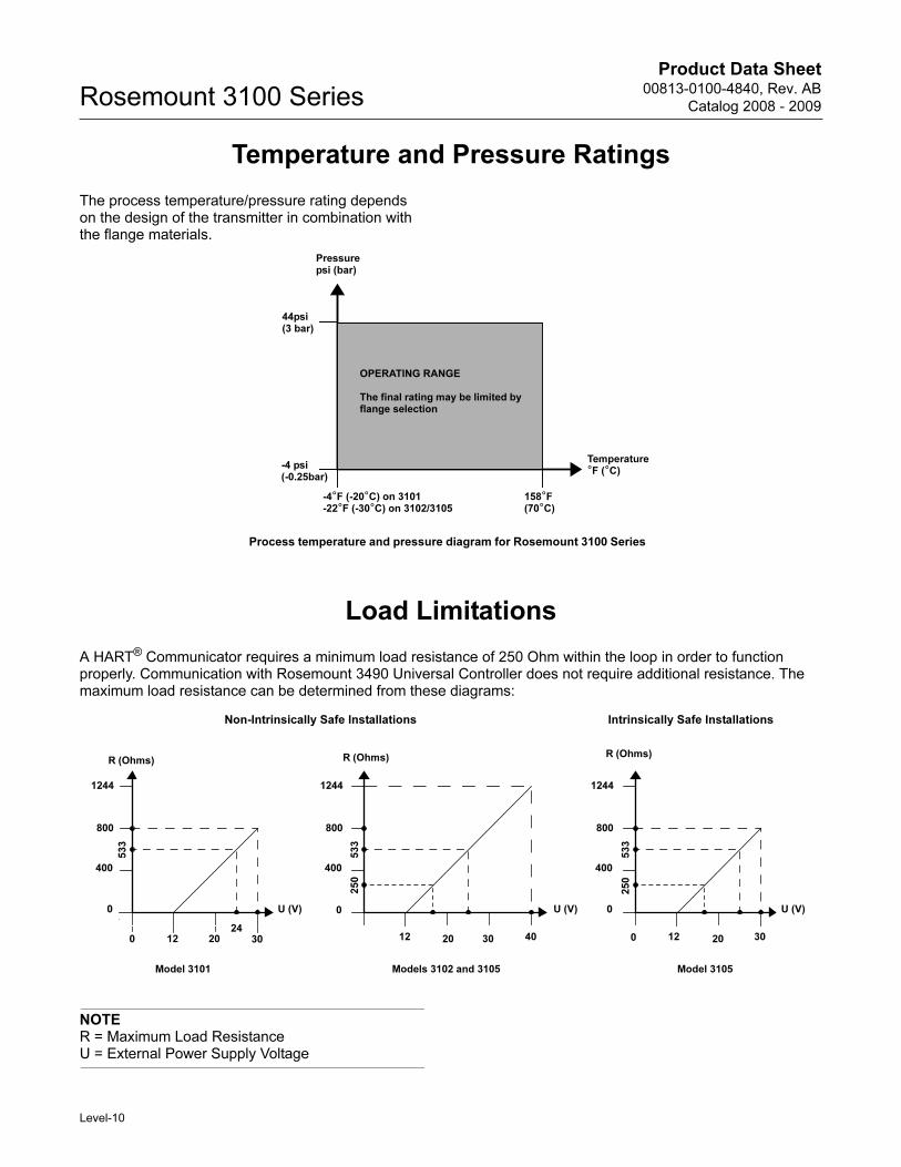
Temperature and Pressure Ratings
The process temperature/pressure rating depends on the design of the transmitter in combination with the flange materials.
Load Limitations
A HART® Communicator requires a minimum load resistance of 250 Ohm within the loop in order to function properly. Communication with Rosemount 3490 Universal Controller does not require additional resistance. The maximum load resistance can be determined from these diagrams:
NOTER = Maximum Load ResistanceU = External Power Supply Voltage
Pressurepsi (bar)
158°F (70°C)
-4°F (-20°C) on 3101-22°F (-30°C) on 3102/3105
-4 psi(-0.25bar)
44psi(3 bar)
OPERATING RANGE
The final rating may be limited by flange selection
Temperature°F (°C)
Process temperature and pressure diagram for Rosemount 3100 Series
U (V)
R (Ohms)
0
Non-Intrinsically Safe Installations Intrinsically Safe Installations
R (Ohms) R (Ohms)
U (V) U (V)
12 12 304030
1244
800
400
12 2024
533
Model 3101 Models 3102 and 3105
0
1244
800
400
0
20 30 20
1244
800
400
0
Model 3105
250
250
533
533
0
Level-10
Product Data Sheet00813-0100-4840, Rev. AB
Catalog 2008 - 2009 Rosemount 3100 Series
Product Certifications
ORDINARY LOCATION CERTIFICATION FOR FM (MODELS 3101/3102)G5 Project ID: 3024095
The transmitter has been examined and tested to determine
that the design meets basic electrical, mechanical, and fire
protection requirements by FM, a nationally recognized
testing laboratory (NRTL) as accredited by the Federal
Occupational Safety and Health Administration (OSHA).
ORDINARY LOCATION CERTIFICATION FOR CSA (MODELS 3101/3102)G6 Project ID: 1878089
The transmitter has been examined and tested to determine
that the design meets basic electrical, mechanical, and fire
protection requirements by CSA, a nationally recognized
testing laboratory as accredited by the Standards Council of
Canada (SCC).
EUROPEAN DIRECTIVE INFORMATION
The EC declaration of conformity for all applicable
European directives for this product can be found on
the Rosemount website at www.rosemount.com. A
hard copy may be obtained by contacting your local
sales office.
ATEX Directive (94/9/EC)
Complies with the ATEX Directive.
Pressure Equipment Directive (PED) (97/23/EC)
3100 Series is outside the scope of PED Directive.
Electro Magnetic Compatibility (EMC) Directive
EN61326 (Class B)
CE-mark
Complies with applicable directives
3101, 3102 (EMC)
3105 (EMC, ATEX)
HAZARDOUS LOCATIONS CERTIFICATIONS (MODEL 3105)
Factory Mutual (FM) Approvals
Factory Mutual (FM) Intrinsically Safe
Approval
I5 Project ID: 3024095
Intrinsically Safe for Class I, Div. 1, Groups A, B, C and D
Intrinsically Safe for Class I, Zone 0, AEx ia IIC
Temperature Code: T4 at +60°C, max ambient
Temperature Code: T6 at +55°C, max ambient
Control Drawing: 71097/1216
Ui = 30 V, li = 120 mA, Pi = 0.82 W, Li = 108 μH, Ci = 0 μF.
Factory Mutual (FM) Non-Incendive
Approval
I5 Project ID: 3024095
Non-Incendive for Class I, Div. 2, Groups A, B, C and D
Non-Incendive for Class I, Zone 2, AEx nA IIC
Temperature Code: T4 at +60°C, max ambient
Temperature Code: T6 at +55°C, max ambient
Control Drawing: 71097/1216
Ui = 30 V, li = 120 mA, Pi = 0.82 W, Li = 108 μH, Ci = 0 μF
Canadian Standards Association (CSA) Approvals
Canadian Standards Association (CSA)
Intrinsically Safe Approval
I6 Project ID: 07 CSA 1878089
Intrinsically Safe for Class I, Div. 1, Groups A, B, C, and D
Intrinsically Safe for Class 1, Zone 0, Ex ia IIC
Temperature Code:
T4 (Tamb -40°C to +60°C)
T6 (Tamb -40°C to +55°C)
Control Drawing: 71097/1218
Ui = 30 V, li = 120 mA, Pi = 0.82 W, Li = 108 μH, Ci = 0 μF
Canadian Standards Association (CSA)
Non-Incendive Approval
I6 Project ID: 07 CSA 1878089
Non-Incendive for Class I, Div. 2, Groups A, B, C, and D
Non-Incendive for Class I, Zone 2, Ex nL IIC
Temperature Code:
T4 (Tamb -40°C to +60°C)
T6 (Tamb -40°C to +55°C)
Control Drawing: 71097/1218
Ui = 30 V, li = 120 mA, Pi = 0.82 W, Li = 108 μH, Ci = 0 μF
Level-11
Product Data Sheet00813-0100-4840, Rev. AB
Catalog 2008 - 2009Rosemount 3100 Series
ATEX Intrinsically Safe ApprovalI1 Certificate: Sira 06ATEX2260X
Intrinsically Safe for II 1 G, EEx ia IIC
Temperature Class:
T4 (Tamb -40°C to +60°C)
T6 (Tamb -40°C to +55°C)
Ui = 30 V, li = 120 mA, Pi = 0.82 W, Li = 108 μH, Ci = 0 μF
Special conditions for safe use:
1. All transmitter models have external plastic parts, which
could present a risk of ignition due to electrostatic charge
build-up. They shall not be directly installed in any process
where its enclosure might be charged by the rapid flow of
non-conductive media.
2. All transmitter models shall only be cleaned with a damp
cloth.
3. When the transmitter housing uses aluminum alloy in its
construction, this presents a risk of ignition due to impact
and shall be taken into consideration on installation and use.
IECEx ApprovalI7 Certificate: IECEx SIR 06.0068X
Intrinsically Safe for Zone 0, Ex ia IIC
Temperature Class:
T4 (Tamb -40°C to +60°C)
T6 (Tamb -40°C to +55°C)
Ui = 30 V, li = 120 mA, Pi = 0.82 W, Li = 108 μH, Ci = 0 μF
Special conditions for safe use:
1. All transmitter models have external plastic parts, which
could present a risk of ignition due to electrostatic charge
build-up. They shall not be directly installed in any process
where its enclosure might be charged by the rapid flow of
non-conductive media.
2. All transmitter models shall only be cleaned with a cloth.
3. When the transmitter housing uses aluminum alloy in its
construction, this presents a risk of ignition due to impact
and shall be taken into consideration on installation and use.
Level-12
Product Data Sheet00813-0100-4840, Rev. AB
Catalog 2008 - 2009 Rosemount 3100 Series
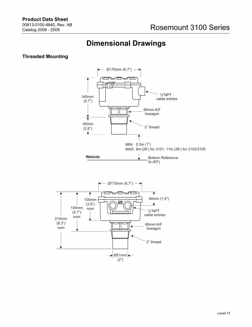
Dimensional Drawings
Threaded Mounting
210mm(8.3”)nom
145mm(5.7”)nom
100mm(3.9”)nom
48mm (1.9”)
Ø51mm(2”)
Ø170mm (6.7”)
60mm A/Fhexagon
2” thread
½”NPTcable entries
½”NPTcable entries
2” thread
Ø170mm (6.7”)
145mm(5.7”)
65mm(2.6”)
60mm A/Fhexagon
MIN: 0.3m (1’)MAX: 8m (26’) for 3101, 11m (36’) for 3102/3105
Wetside Bottom Reference(b.rEF)
Level-13
Product Data Sheet00813-0100-4840, Rev. AB
Catalog 2008 - 2009Rosemount 3100 Series
Ordering Information
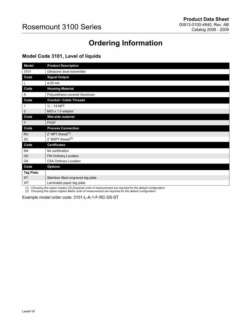
Model Code 3101, Level of liquids
Model Product Description
3101 Ultrasonic level transmitter
Code Signal Output
L 4-20 mA
Code Housing Material
A Polyurethane-covered Aluminum
Code Conduit / Cable Threads
1 ½ - 14 NPT
2 M20 x 1.5 adaptor
Code Wet-side material
F PVDF
Code Process Connection
RC 2” NPT thread(1)
(1) Choosing this option implies US (Imperial) units of measurement are required for the default configuration.
SC 2” BSPT thread(2)
(2) Choosing this option implies Metric units of measurement are required for the default configuration.
Example model order code: 3101-L-A-1-F-RC-G5-ST
Code Certificates
NA No certification
G5 FM Ordinary Location
G6 CSA Ordinary Location
Code Options
Tag Plate
ST Stainless Steel engraved tag plate
WT Laminated paper tag plate
Level-14
Product Data Sheet00813-0100-4840, Rev. AB
Catalog 2008 - 2009 Rosemount 3100 Series
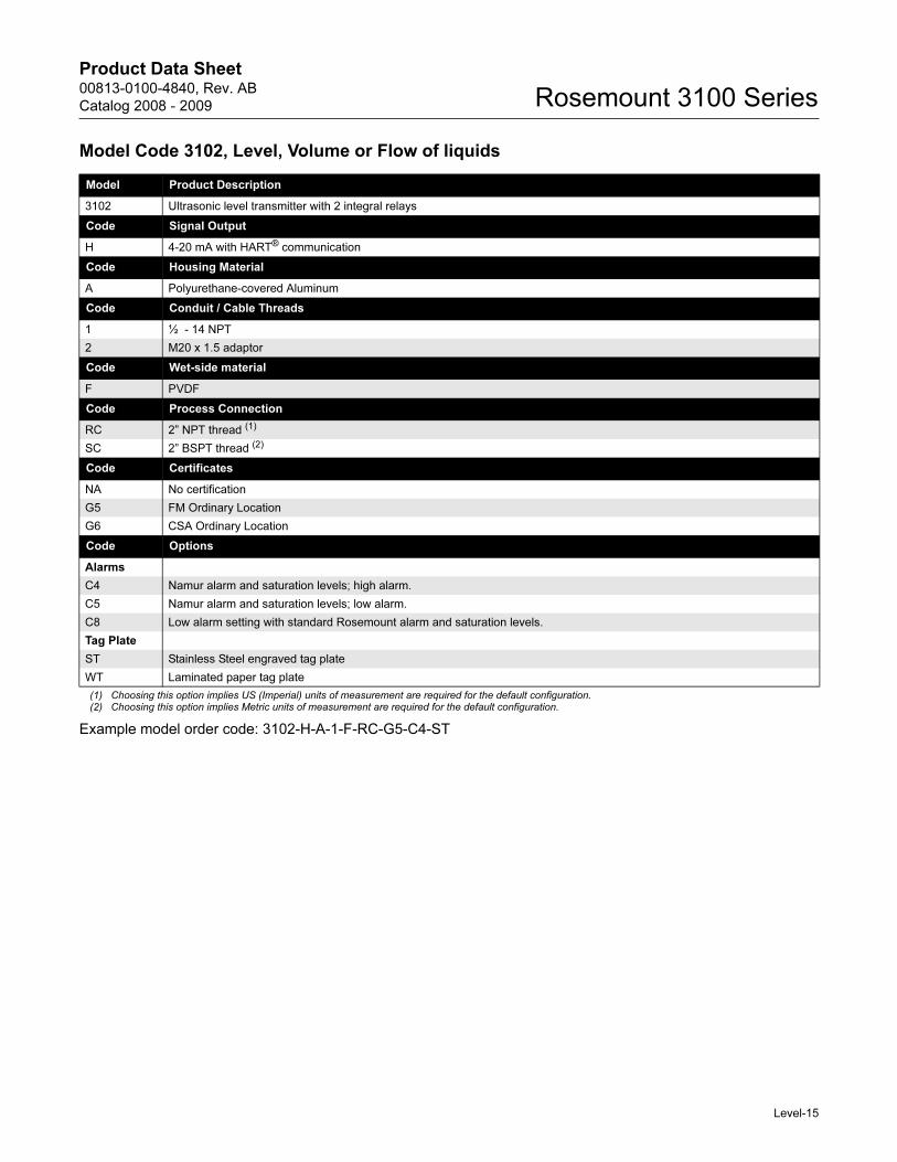
Model Code 3102, Level, Volume or Flow of liquids
Model Product Description
3102 Ultrasonic level transmitter with 2 integral relays
Code Signal Output
H 4-20 mA with HART® communication
Code Housing Material
A Polyurethane-covered Aluminum
Code Conduit / Cable Threads
1 ½ - 14 NPT
2 M20 x 1.5 adaptor
Code Wet-side material
F PVDF
Code Process Connection
RC 2” NPT thread (1)
(1) Choosing this option implies US (Imperial) units of measurement are required for the default configuration.
SC 2” BSPT thread (2)
(2) Choosing this option implies Metric units of measurement are required for the default configuration.
Example model order code: 3102-H-A-1-F-RC-G5-C4-ST
Code Certificates
NA No certification
G5 FM Ordinary Location
G6 CSA Ordinary Location
Code Options
Alarms
C4 Namur alarm and saturation levels; high alarm.
C5 Namur alarm and saturation levels; low alarm.
C8 Low alarm setting with standard Rosemount alarm and saturation levels.
Tag Plate
ST Stainless Steel engraved tag plate
WT Laminated paper tag plate
Level-15
Product Data Sheet00813-0100-4840, Rev. AB
Catalog 2008 - 2009Rosemount 3100 Series
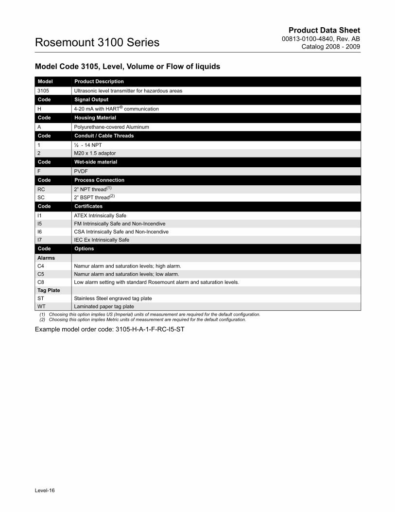
Model Code 3105, Level, Volume or Flow of liquids
Model Product Description
3105 Ultrasonic level transmitter for hazardous areas
Code Signal Output
H 4-20 mA with HART® communication
Code Housing Material
A Polyurethane-covered Aluminum
Code Conduit / Cable Threads
1 ½ - 14 NPT
2 M20 x 1.5 adaptor
Code Wet-side material
F PVDF
Code Process Connection
RC 2” NPT thread(1)
(1) Choosing this option implies US (Imperial) units of measurement are required for the default configuration.
SC 2” BSPT thread(2)
(2) Choosing this option implies Metric units of measurement are required for the default configuration.
Example model order code: 3105-H-A-1-F-RC-I5-ST
Code Certificates
I1 ATEX Intrinsically Safe
I5 FM Intrinsically Safe and Non-Incendive
I6 CSA Intrinsically Safe and Non-Incendive
I7 IEC Ex Intrinsically Safe
Code Options
Alarms
C4 Namur alarm and saturation levels; high alarm.
C5 Namur alarm and saturation levels; low alarm.
C8 Low alarm setting with standard Rosemount alarm and saturation levels.
Tag Plate
ST Stainless Steel engraved tag plate
WT Laminated paper tag plate
Level-16
Product Data Sheet00813-0100-4840, Rev. AB
Catalog 2008 - 2009 Rosemount 3100 Series
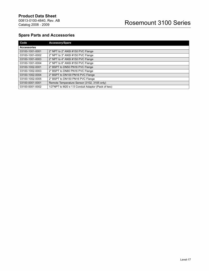
Spare Parts and Accessories
Code Accessory/Spare
Accessories
03100-1001-0001 2" NPT to 2" ANSI #150 PVC Flange
03100-1001-0002 2" NPT to 3" ANSI #150 PVC Flange
03100-1001-0003 2" NPT to 4" ANSI #150 PVC Flange
03100-1001-0004 2" NPT to 6" ANSI #150 PVC Flange
03100-1002-0001 2" BSPT to DN50 PN16 PVC Flange
03100-1002-0003 2" BSPT to DN80 PN16 PVC Flange
03100-1002-0004 2" BSPT to DN100 PN16 PVC Flange
03100-1002-0005 2" BSPT to DN150 PN16 PVC Flange
03100-0001-0001 Remote Temperature Sensor (3102, 3105 only)
03100-0001-0002 1/2"NPT to M20 x 1.5 Conduit Adaptor (Pack of two)
Level-17

Product Data Sheet00813-0100-4840, Rev. AB
Catalog 2008 - 2009Rosemount 3100 Series
NOTES:
Level-18

Product Data Sheet00813-0100-4840, Rev. AB
Catalog 2008 - 2009 Rosemount 3100 Series
NOTES:
Level-19
Product Data Sheet00809-0100-4840, Rev. AB
Catalog 2008 - 2009 Rosemount 3100 Series
The Emerson logo is a trademark and service mark of Emerson Electric Co.Rosemount and the Rosemount logotype are registered trademarks of Rosemount Inc.PlantWeb is a registered trademark of one of the Emerson Process Management group of companies.HART is a registered trademark of the HART Communication Foundation.DeltaV is a registered trademark of Emerson Process Management group of companies.All other marks are the property of their respective owners.
Standard Terms and Conditions of Sale can be found at www.rosemount.com\terms_of_sale
© 2008 Rosemount Inc. All rights reserved.
www.rosemount.com
Emerson Process Management, Rosemount Inc.
The AmericasEmerson Process Management8200 Market BoulevardChanhassen, MN 55317 USAT (U.S.) 1-800-999-9307T (International) (952) 906-8888F (952) 949-7001
Europe, Middle East & AfricaEmerson Process ManagementShared Services Ltd.Heath PlaceBognor RegisWest Sussex PO22 9SHEnglandTel 44 1243 845500Fax 44 1243 867554
Asia PacificEmerson Process ManagementSingapore Pte Ltd.1 Pandan CrescentSingapore 128461Tel 65 6777 8211Fax 65 6777 [email protected]