rooftop installation manual - sunlock installation manual_v4.4.pdf · rooftop installation manual...
TRANSCRIPT

Rooftop Installation ManualVersion 4.4 – updated April 2013
www.sunlock.com.au
Australian Made
Rooftop installation manual – Version 4.4 (updated April 2013) 2
contents
Introduction 3
safety and Installer Responsibilities 4
Handling and Installing SunLock 4
Wind and Climate Design 4
technical specifications 5
Applications 5
Features 5
Custom Design 5
Before Installing 6
Receipt of Goods 6
Tools Required for Installation 6
sunLock components 7
Designing Your Framing system 11
Determining Wind terrain category 12
Fixing Locations and Array Placement 13
Wind Region Map Australia (in accordance with As/nZs 1170.2:2011/Amdt 2:2012) 14
Installation 15
Installing L-Feet on Steel Roofs 15
Installing Tile Brackets 16
Warranty Against Defects 19
consumer Guarantees 20
contact Details 20
Maintenance and cleaning 21
References 21
certificate of compliance 21
technical Drawings 22
S1.1 22
S1.2 23
S2.1 24
S2.2 25
S3.1 26
S3.2 27
S4.1 28
S4.2 29
S5.1 30
S5.2 31

Rooftop installation manual – Version 4.4 (updated April 2013) 3
IntRoDuctIon
Thank you for choosing the SunLock solar panel roof mounting system. Made from custom-designed aluminium extrusions and components, SunLock’s streamlined design and improved frame strength greatly simplify solar panel installation.
Offering a high level of adjustability for module width and depth SunLock’s versatile design makes it suitable for a wide variety of building types and zones including residential, commercial and remote environments.
SunLock is backed by a 10-year warranty and is compliant with the AS/NZS 1170.2:2011/Amdt 2:2012 on wind actions, AS/NZS16641.1:1997 on aluminium structures, AS1720.1:2012 on timber structures, AS/NZS4600:2005 on cold-formed steel structures.
WARnInG
Indicates a potentially hazardous situation which, if not avoided, could result in death or serious injury. This symbol is not used for hazards relating to property damage unless there is also a risk of personal injury to this level.
cAutIon
Indicates a potentially hazardous situation which, if not avoided, may result in minor or moderate injury. It may also be used to draw attention to unsafe practices that may cause damage to property.

Rooftop installation manual – Version 4.4 (updated April 2013) 4
Handling and Installing sunLock
It is critically important that safety practices are observed when installing SunLock.
Do not throw or roughly handle any SunLock components.
Do not bring SunLock into contact with sharp or heavy objects.
Do not modify SunLock components in any way. The exchange of bolts, drilling of holes, bending or any other physical changes not described in standard installation procedure will void the warranty.
It is the installer’s responsibility to verify the integrity of the structure to which SunLock is fixed. Roofs or structures with rotten/rusted purlins, undersized purlins, excessively spaced purlins, or any other unsuitable substructure cannot be used with SunLock, and installation on such structures will void the warranty, and could result in death or serious injury.
Wind and climate Design
A SunLock frame installed in accordance with this installation manual is compliant with AS/NZS 1170.2:2011/Amdt 2:2012.
This manual (including the drawings) cannot cover all types of buildings and eventualities.
For buildings outside the limits stated on the drawings (maximum 10 m roof height, maximum roof pitch 30°, slopes, hills) contact a structural engineer for a custom design.
AS/NZS 1170.2:2011/Amdt 2:2012 provides guidance on determining the wind pressures applicable to your SunLock install site, taking into account roof shape and geographic location. Sufficient guidance is given in this document, but you may wish to procure a copy of these standards if your company installs Australia/New Zealand wide.
REMEMBER average wind speeds are higher for structures mounted closer to the roof perimeter zone (edge).
Make sure your installation complies with local and national building codes. Take into account relevant design parameters (wind speed, exposure and topographic factor) when determining the loading for the installation.
If alternative fasteners are used to fix the framing to the roof (assuming supplied fasteners are unsuitable for any reason), all screw fasteners must conform to corrosion resistance Class 4 Australian Standard AS3566 and be of equal or greater strength to those supplied with your SunLock order.
InstALLAtIon oF tHIs PRoDuct Is to Be PeRFoRMeD onLY BY PRoFessIonALLY tRAIneD InstALLeRs.
Any attempt by an unqualified person to install this product could result in death or serious injury.
sAFetY AnD InstALLeR ResPonsIBILItIes

Rooftop installation manual – Version 4.4 (updated April 2013) 5
custom Design
A SunLock frame can be designed to suit almost any roof and wind region, including buildings up to 200 m in height, roof pitches up to 65°, and located on slopes or hills.
For a custom design please contact either SunLock or an Australian registered structural engineer.
tecHnIcAL sPecIFIcAtIons
Applications
Commercial and residential buildings
Marine applications and remote areas
Features
6106-T6 aluminium extrusion with 210 MPa yield strength
Ripple design on rail, L-foot and tile brackets increases joint strength
Suitable for buildings up to 10 m in height
Suitable for roof slopes in the range from 5° to 30°
Inherent corrosion resistance resulting in low ongoing maintenance and an extended product life.
Complies with Australian/New Zealand Standard on Wind Actions, AS/NZS 1170.2:2011/Amdt 2:2012
Optional anodised finish (standard is mill finish)
Australian design and manufacture

Rooftop installation manual – Version 4.4 (updated April 2013) 6
BeFoRe InstALLInG
Receipt of Goods
Check that the SunLock equipment is undamaged and that the order is complete. Check for correct quantities of the following items:
Rails: slightly more than twice the length of the proposed solar array in linear metres
End clamps: a minimum of 4 per row (unless 3 rails are required) of panels (fitted at the ends)
Mid clamps: 2 for every gap between neighbouring panels, e.g. number of panels in row, minus one, multiplied by two.
L-feet or Tile Brackets: at least 2 for each panel; L-feet, roof screws and isolation washers for steel roof interfaces; tile brackets and rafter screws for tile roofs. Refer to the drawings to determine the number of fixings required.
tools Required for Installation
T-bar Allen Key or 6 mm hexagonal driver bit. If using a 6 mm driver bit, make sure the cordless power tool used for driving has a hand-tight clutch setting and a fine (soft) impact drive to prevent damage to the fragile glass panels and threads on the SunLock framing.
cAutIon
Refer to the section ‘Designing Your Framing System’ before attempting installation. Failure to correctly establish the requirements of the proposed installation site is dangerous and will void the framing warranty.
Drill or impact driver for driving roof material fixings.
Gloves for handling SunLock framing (aluminium can develop sharp corners).
For terracotta tile roof installation, an angle grinder fitted with a continuous edge diamond tipped tile-cutting blade; gloves, hearing protection, a face protection mask, and a suitably rated breathing protection mask for all people in proximity of grinding.

Rooftop installation manual – Version 4.4 (updated April 2013) 7
sunLock coMPonents
SL2R – Rails, in pairs, hold each panel row and are custom designed and Australian made 6106-T6 extruded aluminium.
Note: custom rail lengths available on request. Minimum order quantity, deposit & lead time apply.
SLJ150 – Joiners extend SunLock Rails to any length as required by the quantity or width of the solar panels.
SLLF – L-foot roof mounts secure the railing to steel roofs.
Each L-foot is supplied with a potable grade EPDM washer to prevent water ingress or galvanic corrosion with the roof material.
SLLF002 – standard, with a 75 mm roofing screw
SLLF004 – with a Tek screw
SLLF005 – with a 10 mm hole in the base
Rail lengths
For standard 808 mm wide panels
For wider 990 - 1005 mm wide panels
2600 mm 2100 mm
3410 mm 3200 mm
4200 mm

Rooftop installation manual – Version 4.4 (updated April 2013) 8
SLTB005 – Adjustable tile brackets allow adjustment of the elevation and side position of the bracket to provide a closer fit for different tile batten heights, tile profiles, and tile positions. Each tile bracket includes two 90 mm roofing screws. If attaching to hardwood of minimum joint group JD2, these can be substituted by 50 mm screws.
SLECF - Fixed end clamps are available in 35, 38, or 45 mm heights, and are simple and fast to install.
SLECF35 – 35 mm panels
SLECF38 – 38 mm panels
SLECF45 – 45 mm panels
sunLock coMPonents (contInueD)
SLEC – Adjustable End Clamps allow the easy modification of the clamp to suit almost any panel frame height. Note: Minimum of two fins must be engaged.
SLEC003 – 30 - 42 mm panels
SLEC004 – 34 - 46 mm panels
SLEC006 – 46 - 58 mm panels

Rooftop installation manual – Version 4.4 (updated April 2013) 9
sunLock coMPonents (contInueD)
SLMC – Mid clamps fit between panels and hold the panels to the rails. Two variations are available, differing only by the length of the cap screw.
SLMC024 – 30 - 40 mm panels
SLMC026 – 40 - 50 mm panels
Note: Other panel thickness accommodated by special orders.
SLEL – EarthLock system comprises the EarthLock washer (SLELW01) and the EarthLock bonding terminal (SLELBT02). This system provides earth continuity from each panel frame to the rail, allowing the quick and effective connection of the array to an earthing cable if required.
SLIMB03 – Isolator Mounting Bracket is easily attached to the SunLock rail and provides a mounting surface for the rooftop DC isolator.

Rooftop installation manual – Version 4.4 (updated April 2013) 10
sunLock coMPonents (contInueD)
SLTL – Tilt Leg kits comprise one front leg and one rear leg. The front leg is 150 mm long.
SLTL300 – 300 mm rear leg
SLTL500 – 500 mm rear leg
SLTL600 – 600 mm rear leg
SLTL700 – 700 mm rear leg
SLTL800 – 800 mm rear leg
SLCA – Channel Assembly allows tilt arrays to be correctly inclined, even if the purlins are not ideally spaced or located. The channel has outer dimensions of 41.3 x 41.3 mm and is extruded from 6061-T6 structural grade aluminium with a minimum yield strength of 240 MPa.
SLCA1500 – 1500 mm long, 2 L-feet
SLCA2000 – 2000 mm long, 2 L-feet
SLCA3000 – 3000 mm long, 2 L-feet
SLTBLA – Tile bracket landscape adaptors can be used in conjunction with a tile bracket to convert a traditional portrait solar array into landscape format.
SLDB1200 - Diagonal brace is to be used on each end of each row of the tilt array to provide bracing against side loads.

Rooftop installation manual – Version 4.4 (updated April 2013) 11
The ten drawings are as follows:
S1.1 – Tile roofs (terrain category 2)
S1.2 – Tile roofs (terrain category 3)
S2.1 – Tin roofs with steel purlins (terrain category 2)
S2.2 – Tin roofs with steel purlins (terrain category 3)
S3.1 – Tin roofs with timber battens (terrain category 2)
S3.2 – Tin roofs with timber battens (terrain category 3)
S4.1 – Tilt legs on roofs with steel purlins (terrain category 2)
S4.2 – Tilt legs on roofs with steel purlins (terrain category 3)
S5.1 – Tilt legs on roofs with timber battens (terrain category 2)
S5.2 – Tilt legs on roofs with timber battens (terrain category 3)
The installation site, roof material, roof angle, the size and quantity of solar panels and the number of module rows used will determine the dimensions, quantity and layout of framing components required for installation. This section of the installation manual can assist you to determine critical job specifications.
In most cases the SunLock frame itself (rails and clamps) is strong enough to withstand any wind load. When designing the frame, the two main points to consider are:
ensuring sufficient fixings are used to hold the SunLock frame to the roof frame
ensuring the roof frame itself is not overloaded by the extra wind load from the solar system
Ten drawings have been supplied with this installation manual, one for each roof type. Select the appropriate drawing for the installation site and follow the detailed instructions contained within it.
Note the following details:
When a panel ‘covers’ three roof battens, then three rails should be used. This ensures that the battens are not overloaded by the point loads from the L-feet. In other words, for tin roof installations where the purlin spacing is less than 750 mm, three rails should be used per row of panels.
Ensure panels are installed in accordance with the solar panel manufacturer’s installation manual. Typically, these manuals state that the clamps holding the panel to the rail must be installed in a certain region, commonly a maximum of 10-25% of the length of the panel from each end of the panel.
Design your system:
1. Select the wind terrain category
2. Select the correct drawing
3. Determine the width of the edge zone
4. Read off the maximum fixing spacing and calculate the total number of fixings required
DesIGnInG YouR FRAMInG sYsteM

Rooftop installation manual – Version 4.4 (updated April 2013) 12
DeteRMInInG WInD teRRAIn cAteGoRY
terrain category 2
Open terrain, including grassland with well scattered obstructions having heights generally from 1.5 metres to 5 metres. Examples include farmland or cleared sub-divisions with isolated trees and uncut grass.
terrain category 3
Terrain with numerous closely spaced obstructions having heights generally from 3 metres to 10 metres. Examples include typical suburban housing or light industrial areas.
Terrain Category 2 (TC2)
Terrain Category 3 (TC3)

Rooftop installation manual – Version 4.4 (updated April 2013) 13
Determining the width of the edge and intermediate zones, ‘A’
The width of the edge and and intermediate zones, ‘A’, is determined by calculating each of the following values, and then using the smallest:
0.2 x B 0.2 x D H
Determining the width of the central and end zones, ‘B/3’
The width of the central and end zones is determined by calculating the roof length and dividing this result by 3.
An exclusion zone of 200 mm must be made on the edges of the roof.
FIxInG LocAtIons AnD ARRAY PLAceMent
Solar panels can be installed anywhere on the roof, as long as sufficient fixings are used. Higher wind speeds are encountered at the edges of roofs and therefore more fixings are required in these areas.
For a flush mounted array, a roof can be divided into two zones, the central zone and the end zone. The width of these zones can be determined based on the length of the building.
For a tilted array, a roof can be divided into three zones, the internal zone, intermediate zone and the edge zone. The width of these outer zones can be determined based on the length, width and average height of the building.
If fixings are located in the intermediate, edge or end zones, then the maximum spacing to the next fixing must be reduced, as per the table in the drawings.
Flush mounted arrays:
Tilt mounted arrays:

Rooftop installation manual – Version 4.4 (updated April 2013) 14
Region A
Region C
Region D
Region B
20˚
25˚25˚
30˚27˚
30˚
50km
100km
150km
WInD ReGIon MAP AustRALIA (in accordance with As/nZs 1170.2:2011/Amdt 2:2012)
Included towns:
Region A:
Callytharra Springs
Gascoyne Junction
Green Head
Kununurra
Lord Howe Island
Morawa
Toowoomba
Wittanoom
Bourke
Region B:
Adelaide River
Atherton
Biloela
Brisbane
Christmas Island
Collinsville
Corindi
Geraldton
Ivanhoe
Kyogle
Marble Bar
Mullewa
Norfolk Island
Torres Strait Islands
Wyndham
Region C:
Borroloola
Broome
Bundaberg
Burketown
Cairns
Cocos Islands
Darwin
Derby
Karumba
Mackay
Mareeba
Millstream
Moreton
Nhulunbuy
Normanton
Rockhampton
Townsville
Region D:
Carnarvon
Exmouth
Karratha
Onslow
Port Hedland

Rooftop installation manual – Version 4.4 (updated April 2013) 15
For a steel roof with exposed fixings
1. Determine where the roof mounts will be positioned based on position of existing roof screws.
2. Do not remove existing roof screws. Instead, install on unused crest. This is because the existing screws are there to hold down the roof sheet, while the new screws are there to hold down the solar system.
3. Fix L-feet in place and fix with the upright part of the ‘L’ facing towards the ridge of the roof.
4. Secure the L-foot roof mounts with the roof screws. Use the supplied isolation washers between the base of the L-foot and the roof surface.
For a steel roof with hidden fixings (clip-type roofing)
1. Lift the sheets of steel to expose the structure beneath.
2. Using a marker, mark out the precise locations of the structure below the roofing material and clip the roof back in place.
3. Place L-feet on the markings and screw down with supplied isolation washers between the base of the foot and the roof surface.
Note: SunLock can only be attached to “406” style roof sheets.
L-foot fits to the crest
InstALLAtIon
Start any roof/structure installation by marking the fixing points at the calculated centres and spacing along the proposed length of the array (in a parallel row).
Installing L-Feet on steel Roofs:

Rooftop installation manual – Version 4.4 (updated April 2013) 16
Installing tile Brackets
Installation of the SLTB005 Adjustable Tile Bracket requires no special tools – only a 13 mm socket/spanner and the 6 mm internal hex driver/Allen key normally used for SunLock framing.
Expose the timber rafters where the SunLock Tile Brackets are to be attached by sliding or removing tiles at a suitable spacing
Loosely assemble the tile brackets ready for adjustment. Place the first tile bracket on a rafter and adjust the elevation to a low and flush fit. Use a 13 mm socket to secure the bolt assembly. Generally, the other brackets on the roof can be adjusted to the same elevation position.
Attach the tile brackets to the rafters using the supplied screws. To prevent splitting the timber, pre-drill the screw holes at an inward facing angle. This is especially important for hardwood rafters.
Move the tiles back into place. Attach the SunLock rails to the Adjustable Tile Bracket uprights, and your framing installation is nearly complete.
Tile brackets are supplied as standard with 90 mm timber roofing screws, which supply the required 80 mm embedment in softwood rafters. For hardwood rafters, the embedment can be reduced to 40 mm (i.e. use at least a 50 mm screw, or longer if you have any packers between the tile bracket and the rafter).
If the purlins are steel (e.g. cold formed galvanized c-sections), note that Tek screws cannot be used unless the purlin is at least 3 mm thick, as they do not have sufficient pull out capacity. Other options are to position a section of timber in the section and screw into the timber, or use bolts, washers and nuts.
InstALLAtIon (contInueD)

Rooftop installation manual – Version 4.4 (updated April 2013) 17
2. Connecting Rail to Roof Mounts The rail can be adjusted vertically within the roof attachment slot when bolts are loosely fastened.
3. Connecting Multiple Rails Join rail segments by inserting the rail joiner into the rail channel.
4. Connecting Multiple RailsFasten cap screws to secure.
5. Installing End Clamps Insert keylock of the end clamp into the rail channel. Using a 6 mm hex driver/Allen key, secure the first solar panel to the railing starting as close to the end of the row as possible. A minimum of 50 mm between the end of the rail and edge of the first solar panel is required.
6. Installing Mid Clamps Insert the keylock of the mid clamp into the rail channel and position the clamp against the first panel frame. Hand-tighten the screw 2-3 turns to loosely hold the clamp in position. Ensure the EarthLock washer is placed between the SunLock rail and the frame of the panel.
InstALLAtIon (contInueD)
1. Connecting Rail to Roof Mounts Connect the rail to the roof mounts by inserting the roof mount keylock into the rail channel. Make sure the ridged rail surface faces the ridged surface of roof attachments. Fasten the cap screw on the keylock 2-3 turns to loosely hold the rail in position.

Rooftop installation manual – Version 4.4 (updated April 2013) 18
7. Installing Mid Clamps Slide second panel firmly into place against the mid clamps and fasten bolts.
8. Check Alignment of the Array After fixing the first 2 panels, check that the array is straight. If there appears to be a deviation from square (e.g. if the ridge cap shows the row to be falling or rising slightly), readjust the panels until they appear square with the roof. Alternatively, measure the distance from the rail to the edge of the panel.
9. Continue Installing Mid Clamps Continue to clamp the neighbouring panels in the array to the rails.
10. Install End ClampsFinish the array row by securing the remaining two end clamps. You should have a minimum of 50 mm clearance between the edge of the last panel and the end of the rail. Tighten all bolts to secure the panels.
11. EarthLock Bonding Terminal Fasten the EarthLock Bonding Terminal directly to a SunLock rail by placing the insert key in the rail and tightening the cap screw.Note: The SLELBT02 can be connected to the top or the side of the rail.
12. Isolator mounting bracket Fasten the Isolator Mounting Bracket to the end of the SunLock rail. The DC isolator can then be fixed to this plate.
InstALLAtIon (contInueD)

Rooftop installation manual – Version 4.4 (updated April 2013) 19
WARRAntY AGAInst DeFects
Energy Matters Pty Ltd (trading as Energy Matters and Apollo Energy) (Energy Matters) is the manufacturer of the Sunlock Solar Module Mounting System (Frame).
Energy Matters warrants, on the terms set out below, that the Frame will be free from defects in materials and workmanship for a period of 10 years from the date on which the Frame is purchased from Energy Matters (Warranty against Defects).
transferability
Our Warranty against Defects is only provided to the original purchaser of the Frame from Energy Matters (Purchaser) or, where the Purchaser is an installer or builder who on-supplies the Frame to another party, to that other party (End-User). Our Warranty against Defects is not otherwise transferable.
Making a claim
If you believe that the Frame is defective and you are an End-User, you may either make a claim against the installer or builder from whom you purchased the Frame or you may make a claim against us directly.
In order to make a claim against us, you must post, fax or email us a notice, using the contact details set out below. In your notice you must provide:
details of why you believe the Frame is defective;
a copy of your invoice, receipt or any other document which provides proof of purchase;
details of any expenses you have incurred in making your claim; and
details of how we should contact you.
Within a reasonable time after receipt of your claim we will contact you to arrange a time to attend the premises at which the Frame is located.
Remedies
If we determine that the Frame is defective and the defect is not a major failure then, if possible, we will try to repair the defective Frame at the premises. If this is not possible, we will remove the defective Frame and provide a replacement Frame at our expense.
If we determine that the Frame is defective and the defect is a major failure then you have the option of rejecting the Frame and obtaining a refund from us, rejecting the Frame and obtaining a replacement Frame from us at our expense or of keeping the Frame and receiving compensation from us for the difference between the actual value of the Frame and the amount you paid for the Frame.
If we determine that the Frame is defective we will also pay the substantiated reasonable expenses incurred by you in making your claim.
Your obligations
In order to have the benefit of our Warranty against Defects:
if you are a Purchaser, you must have paid all amounts owed by you to Energy Matters in relation to the purchase of the Frame;
you must have complied with all reasonable instructions of Energy Matters (whether written or verbal) in relation to the transport, installation, care, repair and use of the Frame; and
you must not have misused, neglected, damaged or modified the Frame.
exclusions
Our Warranty against Defects does not include:
damage caused to the Frame during shipment or storage of the Frame by a party other than Energy Matters;
damage caused to the Frame during installation by a party other than Energy Matters;
damage caused by ‘Acts of God’, vermin, animals or pests or by other causes or acts outside Energy Matters’ reasonable control; or
normal wear and tear, including normal weathering.
Jurisdiction
Our Warranty against Defects is to be construed in accordance with the laws of Victoria and any disputes will be determined by the exclusive jurisdiction of the courts of Victoria.

Rooftop installation manual – Version 4.4 (updated April 2013) 20
consuMeR GuARAntees
In addition to our Warranty against Defects, the Frame also comes with guarantees that cannot be excluded under the Australian Consumer Law (Consumer Guarantees).
In the event that the Frame fails to satisfy a Consumer Guarantee, you are entitled to a replacement or refund for a major failure and compensation for any other reasonably foreseeable loss or damage. You are also entitled to have the Frame repaired or replaced if the Frame fails to be of acceptable quality and the failure does not amount to a major failure.
Please note that in addition to the rights and remedies set out in this document, you may also have other rights and remedies available to you under the law.
contAct DetAILs
Energy Matters Pty Ltd (trading as Energy Matters and Apollo Energy)
Address: Ground Floor, 359-361 City Rd, Southbank, VIC, 3006
Postal Address: PO Box 5265, South Melbourne, VIC, 3205
Sales and Service:
1300 855 484 (local call from anywhere in Australia)
International: +61 3 9697 1900
Fax: +61 3 9697 1919
Email: [email protected]

Rooftop installation manual – Version 4.4 (updated April 2013) 21
REFERENCES
CERTIFICATE OF COMPLIANCE
AS/NZS 1170.2:2011/Amdt 2:2012 on wind actions
AS/NZS16641.1:1997 on aluminium structures
AS1720.1:2012 on timber structures
AS/NZS4600:2005 on cold-formed steel structures
AS3566-2011, self-drilling screws for the building and construction industries.
MAINTENANCE AND CLEANING
6106-T6 aluminium is largely maintenance free. Only in highly polluted or marine conditions is rinsing with clean water required, during scheduled panel cleaning.

PRODUCT NAME
MANUFACTURER'S NAME
DESIGN CRITERIA
SUNLOCK SOLAR PANEL MOUNTING SYSTEM
ENERGY MATTERS PTY LTD
WIND SPEEDS AND PRESSURES ARECALCULATED IN ACCORDANCE WITHAS/NZS 1170.2: 2011 / AMDT 2:2012
IMPORTANCE LEVEL 2 ANNUAL PROBABILITY OF EXCEEDANCE 1:500 TOPOGRAPHIC MULTIPLIER M = 1.0 (FLAT) TERRAIN CATEGORY = 2; Mz,CAT = 1.0 REGION A; VR = 45 m/s REGION B; VR = 57 m/s REGION C; VR = 69 m/s
PRODUCT DESCRIPTION SOLAR PANEL SUPPORT FRAME AND FIXINGS
FOR SUNLOCK FOR 5° - 30° TILED ROOFS PORTRAIT MOUNTED PANELS SUNLOCK TILE BRACKET SLTB005
THE EXISTING ROOF CONSTRUCTION SHALLBE VERIFIED TO ENSURE ITS SUITABILITYFOR THIS PRODUCT AND THAT IT IS CAPABLEOF SUPPORTING THE ADDITIONAL LOADS.
IF THE BUILDING IS SITUATED ANYWHEREOTHER THAN ON A FLAT AREA (IE. A SLOPE,A HILL ETC) DO NOT USE THIS DRAWING.CONTACT A STRUCTURAL ENGINEER FOR ACUSTOM DESIGN.
MAXIMUM ROOF HEIGHT= 10m MINIMUM 5° ROOF PITCH MAXIMUM 30° ROOF PITCH H/B < 0.5 & H/D < 0.5 SOLAR PANELS TO BE CERTIFIED
SEPARATELY MAXIMUM SOLAR PANEL 1680mm x 1000mm FOR RAIL AND RAIL FIXING ONLY. MAX ULTIMATE UP-LIFT FORCE PER TILE
BRACKET 1.03kN TIMBER RAFTERS TO SUPPORT FRAME TO BE
JOINT GROUP J4 OR BETTER
LIMITATIONS
- TABLE VALUES FOR EQUAL PANEL CANTILEVER- IF PANEL CANTILEVERS ON EACH END OF PANEL DIFFER REDUCE TABLE VALUES BY FACTOR 1.13- PERMISSIBLE PANEL CANTILEVER 10% - 25% OF PANEL SIZE IN ACCORDANCE WITH SOLAR PANEL MANUFACTURER
840
WIND REGION A WIND REGION BLOCATION
MAXIMUM RAFTER SPACING 'S' IN mm, FOR TILED ROOFS OF PITCH 5°-30°
1010
No OF RAILS
2
3
2
3
630
710
525
590
445
370
4 920 575
CENTRALZONE
13054 815
ENDZONE
TERRAIN CATEGORY 2
WIND REGION C
425
355
300
250
390
550
NOT TO SCALE
'D''B'
'H'
AVE
RA
GE
HE
IGH
T
ROOF - INSTALLATION ZONES
H/B < 0.5H/D < 0.5
ENDZONE
ENDZONE
CENTRALZONE
'B'/3
'B'/3
'B'/3
EDGEEXCLUSIONZONE
200
200
NOT TO SCALE
SOLAR PANELSBY OTHERS
EXISTING RAFTER
SUNLOCK TILEBRACKET SLTB005
2 Ø6.3 (14G)TIMBER SCREWS,(PRE-DRILL HOLES)SCREW THREADMINIMUM 80INTO RAFTERTYPICAL
4 FIXINGS PER PANELSUNLOCK END CLAMPOR SUNLOCK MID CLAMP
SUNLOCKRAIL SL2R MAY BE PLACED ONEITHER SIDE OF BRACKET(TYPICAL)
NOT TO SCALE
EXISTING ROOFBATTEN
EXISTINGROOFTILES MAXIMUM RAFTER SPACING 'S'
AS PER TABLE
SUNLOCKRAIL SL2R
SOLAR PANELBY OTHERS
SUNLOCKMID CLAMP
SUNLOCK TILEBRACKET SLTB005
EXISTINGRAFTER
1/3 SMAX.
2 RAIL PANEL FIXING
3 RAIL PANEL FIXING
SOLAR PANELCLAMPINGPOINTS TO RAILS
EQUAL
EQUAL
SUNLOCKEND CLAMP
PANEL FIXING DETAIL 4 RAIL PANEL FIXING
SOLAR PANELCLAMPINGPOINTS TO RAILS
EQUAL
EQUAL
EQUAL
1- 2
-
SECTION 2-
100
SOLAR PANELCLAMPINGPOINTS TO RAILS
NOT TO SCALE
NOT TO SCALE
NOT TO SCALE
NOT TO SCALE
35 MIN.
14
14
SUNLOCKTILEBRACKETSLTB005
EXISTINGRAFTER
SECTION 1-
Rev. Issue / Amendment App. Date Electronic Code Signature Date
DrawnDesign
Scale at A3 Date
Job No. Drg. Amdt.
ELECTRONIC SIGNATURE:THIS DRAWING HAS BEEN ASSIGNED AN ELECTRONIC SIGNATURECODE. THE PRESENCE OF THIS CODE SIGNIFIES THAT THIS IS THECERTIFIED DRAWING ISSUED FOR CONSTRUCTION.
COPYRIGHT: THE DESIGN AND DETAILS SHOWN ON THIS DRAWING ARESPECIFIC TO THIS PROJECT ONLY AND MAY NOT BE REPRODUCED INWHOLE OR IN PART OR BE USED FOR ANY OTHER PROJECT OR PURPOSEWITHOUT THE WRITTEN CONSENT OF PARTRIDGE STRUCTURAL PTY LTD.
PARTRIDGE STRUCTURAL PTY LTD ABN 73 002 451 925
SUNLOCKMOUNTING SYSTEM AND FIXINGS
TILED ROOF 5° - 30° PITCH - TC2TIMBER ROOF STRUCTURE PORTRAIT CONFIGURATION
Client
ENERGY MATTERS PTY LTD
RH JR
N/A FEB 2013
2013S0075 S1.1 A
P1 PRELIMINARY ISSUE RH 15.02.13
P2 PRELIMINARY ISSUE RH 14.03.13
A ISSUED FOR CONSTRUCTION R.H 02.04.13

PRODUCT NAME
MANUFACTURER'S NAME
DESIGN CRITERIA
SUNLOCK SOLAR PANEL MOUNTING SYSTEM
ENERGY MATTERS PTY LTD
WIND SPEEDS AND PRESSURES ARECALCULATED IN ACCORDANCE WITHAS/NZS 1170.2: 2011 /AMDT 2:2012
IMPORTANCE LEVEL 2 ANNUAL PROBABILITY OF EXCEEDANCE 1:500 TOPOGRAPHIC MULTIPLIER M = 1.0 (FLAT) TERRAIN CATEGORY = 3; Mz,CAT = 0.83 REGION A; VR = 45 m/s REGION B; VR = 57 m/s REGION C; VR = 69 m/s
PRODUCT DESCRIPTION SOLAR PANEL SUPPORT FRAME AND FIXINGS
FOR SUNLOCK FOR 5° - 30° TILED ROOFS PORTRAIT MOUNTED PANELS SUNLOCK TILE BRACKET SLTB005
THE EXISTING ROOF CONSTRUCTION SHALLBE VERIFIED TO ENSURE ITS SUITABILITYFOR THIS PRODUCT AND THAT IT IS CAPABLEOF SUPPORTING THE ADDITIONAL LOADS.
IF THE BUILDING IS SITUATED ANYWHEREOTHER THAN ON A FLAT AREA (IE. A SLOPE,A HILL ETC) DO NOT USE THIS DRAWING.CONTACT A STRUCTURAL ENGINEER FOR ACUSTOM DESIGN.
MAXIMUM ROOF HEIGHT= 10m MINIMUM 5° ROOF PITCH MAXIMUM 30° ROOF PITCH H/B < 0.5 & H/D < 0.5 SOLAR PANELS TO BE CERTIFIED
SEPARATELY MAXIMUM SOLAR PANEL 1680mm x 1000mm FOR RAIL AND RAIL FIXING ONLY. MAX ULTIMATE UP-LIFT FORCE PER TILE
BRACKET 1.03kN TIMBER RAFTERS TO SUPPORT FRAME TO BE
JOINT GROUP J4 OR BETTER
LIMITATIONS
1220
WIND REGION A WIND REGION BLOCATION
1465
No OF RAILS
2
3
2
3
910
1035
760
860
645
535
4 1340 835
CENTRALZONE
19004 1180
ENDZONE
TERRAIN CATEGORY 3
- TABLE VALUES FOR EQUAL PANEL CANTILEVER- IF PANEL CANTILEVERS ON EACH END OF PANEL DIFFER REDUCE TABLE VALUES BY FACTOR 1.13- PERMISSIBLE PANEL CANTILEVER 10% - 25% OF PANEL SIZE IN ACCORDANCE WITH SOLAR PANEL MANUFACTURER
MAXIMUM RAFTER SPACING 'S' IN mm, FOR TILED ROOFS OF PITCH 5°-30°
WIND REGION C
615
515
435
360
565
800
NOT TO SCALE
'D''B'
'H'
AVE
RA
GE
HE
IGH
T
ROOF - INSTALLATION ZONES
H/B < 0.5H/D < 0.5
ENDZONE
ENDZONE
CENTRALZONE
'B'/3
'B'/3
'B'/3
EDGEEXCLUSIONZONE
200
200
SOLAR PANELSBY OTHERS
EXISTING RAFTER
SUNLOCK TILEBRACKET SLTB005
2 Ø6.3 (14G)TIMBER SCREWS,(PRE-DRILL HOLES)SCREW THREADMINIMUM 80INTO RAFTERTYPICAL
4 FIXINGS PER PANELSUNLOCK END CLAMPOR SUNLOCK MID CLAMP
SUNLOCKRAIL SL2R MAY BE PLACED ONEITHER SIDE OF BRACKET(TYPICAL)
NOT TO SCALE
EXISTING ROOFBATTEN
EXISTINGROOFTILES MAXIMUM RAFTER SPACING 'S'
AS PER TABLE
SUNLOCKRAIL SL2R
SOLAR PANELBY OTHERS
SUNLOCKMID CLAMP
SUNLOCK TILEBRACKET SLTB005
EXISTINGRAFTER
1/3 SMAX.
2 RAIL PANEL FIXING
3 RAIL PANEL FIXING
SOLAR PANELCLAMPINGPOINTS TO RAILS
EQUAL
EQUAL
SUNLOCKEND CLAMP
PANEL FIXING DETAIL 4 RAIL PANEL FIXING
SOLAR PANELCLAMPINGPOINTS TO RAILS
EQUAL
EQUAL
EQUAL
1- 2
-
SECTION 2-
NOT TO SCALE
SOLAR PANELCLAMPINGPOINTS TO RAILS
NOT TO SCALE
NOT TO SCALE
NOT TO SCALE
100
NOT TO SCALE
35 MIN.
14
14
SUNLOCKTILEBRACKETSLTB005
EXISTINGRAFTER
SECTION 1-
Rev. Issue / Amendment App. Date Electronic Code Signature Date
DrawnDesign
Scale at A3 Date
Job No. Drg. Amdt.
ELECTRONIC SIGNATURE:THIS DRAWING HAS BEEN ASSIGNED AN ELECTRONIC SIGNATURECODE. THE PRESENCE OF THIS CODE SIGNIFIES THAT THIS IS THECERTIFIED DRAWING ISSUED FOR CONSTRUCTION.
COPYRIGHT: THE DESIGN AND DETAILS SHOWN ON THIS DRAWING ARESPECIFIC TO THIS PROJECT ONLY AND MAY NOT BE REPRODUCED INWHOLE OR IN PART OR BE USED FOR ANY OTHER PROJECT OR PURPOSEWITHOUT THE WRITTEN CONSENT OF PARTRIDGE STRUCTURAL PTY LTD.
PARTRIDGE STRUCTURAL PTY LTD ABN 73 002 451 925
SUNLOCKMOUNTING SYSTEM AND FIXINGS
TILED ROOF 5° - 30° PITCH - TC3TIMBER ROOF STRUCTURE PORTRAIT CONFIGURATION
Client
ENERGY MATTERS PTY LTD
RH JR
N/A FEB 2013
2013S0075 S1.2 A
P1 PRELIMINARY ISSUE R.H 15.02.13
P2 PRELIMINARY ISSUE R.H 14.03.13
A ISSUED FOR CONSTRUCTION R.H 02.04.13

EXISTINGTRUSS/RAFTER
SUNLOCK L-FOOTSLLF
PANEL FIXING
SOLAR PANELCLAMPING POINTS
SOLAR PANELSBY OTHERS
SUNLOCK RAIL SL2R
Ø6.3 (14G) TIMBERSCREW 35mmMINIMUM INTOTIMBER BATTENTYPICAL
WATERPROOFSEAL BYINSTALLER
NOT TO SCALE
NOT TO SCALE
EXISTING ROOFBATTEN/ PURLIN
EXISTING METALROOF SHEETING
L-FOOT FIXING
SUNLOCKRAIL SL2R
SUNLOCK ENDCLAMP
SUNLOCK MIDCLAMP
MINIMUM OF ONESUNLOCK L-FOOTSLLF BEYONDSOLAR PANEL
SOLAR PANELBY OTHERS
SUNLOCK RAIL SL2R
MODULE CLAMPS
INTERMEDIATE RAIL OMITTEDAT 900, 1200 & 1300 CL
SOLAR MODULE BY OTHERS
SUNLOCK L-FOOTSLLF
MAX L-FOOT SPACING
REFER TO TABLE
MAX L-FOOT SPACING
REFER TO TABLE
NOT TO SCALE
MAX 1/3L-FOOTSPACING
MAX 1/3 L-FOOT SPACING
PLAN ON SOLAR PANELS
NOT TO SCALE
1-
SECTION 1-
BATTEN / RAILSPACING
BA
TTE
N /
RA
ILS
PA
CIN
G
PRODUCT NAME
MANUFACTURER'S NAME
DESIGN CRITERIA
LIMITATIONS
SUNLOCK SOLAR PANEL MOUNTING SYSTEM
ENERGY MATTERS PTY LTD
WIND SPEEDS AND PRESSURES ARECALCULATED IN ACCORDANCE WITHAS/NZS 1170.2: 2011 / AMDT 2:2012
IMPORTANCE LEVEL 2 ANNUAL PROBABILITY OF EXCEEDANCE 1:500 TOPOGRAPHIC MULTIPLIER M = 1.0 (FLAT) TERRAIN CATEGORY = 2; Mz,CAT = 1.0 REGION A; VR = 45 m/s REGION B; VR = 57 m/s REGION C; VR = 69 m/s REGION D; VR = 88 m/s
THE EXISTING ROOF CONSTRUCTION SHALLBE VERIFIED TO ENSURE ITS SUITABILITYFOR THIS PRODUCT AND THAT IT IS CAPABLEOF SUPPORTING THE ADDITIONAL LOADS.
IF THE BUILDING IS SITUATED ANYWHEREOTHER THAN ON A FLAT AREA (IE. A SLOPE,A HILL ETC) DO NOT USE THIS DRAWING.CONTACT A STRUCTURAL ENGINEER FOR ACUSTOM DESIGN.
MAXIMUM ROOF HEIGHT= 10m MINIMUM 5° ROOF PITCH MAXIMUM 30° ROOF PITCH H/B < 0.5 & H/D < 0.5 SOLAR PANELS TO BE CERTIFIED
SEPARATELY MAXIMUM SOLAR PANEL 1680mm x 1000mm FOR RAIL AND RAIL FIXING ONLY. MAX ULTIMATE UP-LIFT FORCE PER L-FOOT
1.6kN TIMBER BATTENS OR PURLINS TO SUPPORT
FRAME TO BE JOINT GROUP J4 OR BETTER
PRODUCT DESCRIPTION SOLAR PANEL SUPPORT FRAME AND FIXINGS
FOR SUNLOCK FOR 5° - 30° METAL SHEETED ROOFS PORTRAIT MOUNTED PANELS
A B
FOR SHEETED ROOFS OF PITCH 5°-30°
CBATTEN & RAILSPACING DROOF ZONE
MAXIMUM L-FOOT SPACING IN mm FOR TIMBER BATTENS/PURLINS
WIND REGIONS
1570
1305
1290
920
1140
815
805
575
770
550
545
390
475
340
335
240
CENTRALZONE
ENDZONE 900, 1200, 1300
600
900, 1200, 1300
600
TERRAIN CATEGORY 2
- TABLE VALUES FOR EQUAL PANEL CANTILEVER- IF PANEL CANTILEVERS ON EACH END OF PANEL DIFFER REDUCE TABLE VALUES BY FACTOR 1.09- PERMISSIBLE PANEL CANTILEVER 10% - 25% OF PANEL SIZE IN ACCORDANCE WITH SOLAR PANEL MANUFACTURER
NOT TO SCALE
'D''B'
'H'
AVE
RA
GE
HE
IGH
T
ROOF - INSTALLATION ZONES
H/B < 0.5H/D < 0.5
ENDZONE
ENDZONE
CENTRALZONE
'B'/3
'B'/3
'B'/3
EDGEEXCLUSIONZONE
200
200
Rev. Issue / Amendment App. Date Electronic Code Signature Date
DrawnDesign
Scale at A3 Date
Job No. Drg. Amdt.
ELECTRONIC SIGNATURE:THIS DRAWING HAS BEEN ASSIGNED AN ELECTRONIC SIGNATURECODE. THE PRESENCE OF THIS CODE SIGNIFIES THAT THIS IS THECERTIFIED DRAWING ISSUED FOR CONSTRUCTION.
COPYRIGHT: THE DESIGN AND DETAILS SHOWN ON THIS DRAWING ARESPECIFIC TO THIS PROJECT ONLY AND MAY NOT BE REPRODUCED INWHOLE OR IN PART OR BE USED FOR ANY OTHER PROJECT OR PURPOSEWITHOUT THE WRITTEN CONSENT OF PARTRIDGE STRUCTURAL PTY LTD.
PARTRIDGE STRUCTURAL PTY LTD ABN 73 002 451 925
SUNLOCKMOUNTING SYSTEM AND FIXINGS
SHEETED ROOF 5° - 30° PITCH - TC2TIMBER ROOF STRUCTURE PORTRAIT CONFIGURATION
Client
ENERGY MATTERS PTY LTD
RH JR
N/A FEB 2013
2013S0075 S2.1 A
P1 PRELIMINARY ISSUE R.H 15.02.13
P2 PRELIMINARY ISSUE R.H 14.03.13
A ISSUED FOR CONSTRUCTION R.H 02.04.13

EXISTINGTRUSS/RAFTER
SUNLOCK L-FOOTSLLF
PANEL FIXING
SOLAR PANELCLAMPING POINTS
SOLAR PANELSBY OTHERS
SUNLOCK RAIL SL2R
Ø6.3 (14G) TIMBERSCREW 35mmMINIMUM INTOTIMBER BATTENTYPICAL
WATERPROOFSEAL BYINSTALLER
NOT TO SCALE
NOT TO SCALE
EXISTING ROOFBATTEN/ PURLIN
EXISTING METALROOF SHEETING
L-FOOT FIXING
SUNLOCKRAIL SL2R
SUNLOCK ENDCLAMP
SUNLOCK MIDCLAMP
MINIMUM OF ONESUNLOCK L-FOOTSLLF BEYONDSOLAR PANEL
SOLAR PANELBY OTHERS
SUNLOCK RAIL SL2R
MODULE CLAMPS
INTERMEDIATE RAIL OMITTEDAT 900, 1200 & 1300 CL
SOLAR MODULE BY OTHERS
SUNLOCK L-FOOTSLLF
MAX L-FOOT SPACING
REFER TO TABLE
MAX L-FOOT SPACING
REFER TO TABLE
NOT TO SCALE
MAX 1/3L-FOOTSPACING
MAX 1/3 L-FOOT SPACING
PLAN ON SOLAR PANELS
NOT TO SCALE
1-
SECTION 1-
BATTEN / RAILSPACING
BA
TTE
N /
RA
ILS
PA
CIN
G
PRODUCT NAME
MANUFACTURER'S NAME
DESIGN CRITERIA
LIMITATIONS
SUNLOCK SOLAR PANEL MOUNTING SYSTEM
ENERGY MATTERS PTY LTD
WIND SPEEDS AND PRESSURES ARECALCULATED IN ACCORDANCE WITHAS/NZS 1170.2: 2011 / AMDT 2:2012
IMPORTANCE LEVEL 2 ANNUAL PROBABILITY OF EXCEEDANCE 1:500 TOPOGRAPHIC MULTIPLIER M = 1.0 (FLAT) TERRAIN CATEGORY = 3; Mz,CAT = 0.83
REGION A; VR = 45 m/s REGION B; VR = 57 m/s REGION C; VR = 69 m/s REGION D; VR = 88 m/s
THE EXISTING ROOF CONSTRUCTION SHALLBE VERIFIED TO ENSURE ITS SUITABILITYFOR THIS PRODUCT AND THAT IT IS CAPABLEOF SUPPORTING THE ADDITIONAL LOADS.
IF THE BUILDING IS SITUATED ANYWHEREOTHER THAN ON A FLAT AREA (IE. A SLOPE,A HILL ETC) DO NOT USE THIS DRAWING.CONTACT A STRUCTURAL ENGINEER FOR ACUSTOM DESIGN.
MAXIMUM ROOF HEIGHT= 10m MINIMUM 5° ROOF PITCH MAXIMUM 30° ROOF PITCH H/B < 0.5 & H/D < 0.5 SOLAR PANELS TO BE CERTIFIED
SEPARATELY MAXIMUM SOLAR PANEL 1680mm x 1000mm FOR RAIL AND RAIL FIXING ONLY. MAX ULTIMATE UP-LIFT FORCE PER L-FOOT
1.6kN TIMBER BATTENS OR PURLINS TO SUPPORT
FRAME TO BE JOINT GROUP J4 OR BETTER
PRODUCT DESCRIPTION SOLAR PANEL SUPPORT FRAME AND FIXINGS
FOR SUNLOCK FOR 5° - 30° METAL SHEETED ROOFS PORTRAIT MOUNTED PANELS
A B
FOR SHEETED ROOFS OF PITCH 5°-30°
CBATTEN & RAILSPACING DROOF ZONE
MAXIMUM L-FOOT SPACING IN mm FOR TIMBER BATTENS/PURLINS
WIND REGIONS
1775
1585
1655
1340
1655
1180
1165
830
1120
800
790
560
690
495
490
350
CENTRALZONE
ENDZONE 900, 1200, 1300
600
900, 1200, 1300
600
TERRAIN CATEGORY 3
- TABLE VALUES FOR EQUAL PANEL CANTILEVER- IF PANEL CANTILEVERS ON EACH END OF PANEL DIFFER REDUCE TABLE VALUES BY FACTOR 1.09- PERMISSIBLE PANEL CANTILEVER 10% - 25% OF PANEL SIZE IN ACCORDANCE WITH SOLAR PANEL MANUFACTURER
NOT TO SCALE
'D''B'
'H'
AVE
RA
GE
HE
IGH
T
ROOF - INSTALLATION ZONES
H/B < 0.5H/D < 0.5
ENDZONE
ENDZONE
CENTRALZONE
'B'/3
'B'/3
'B'/3
EDGEEXCLUSIONZONE
200
200
Rev. Issue / Amendment App. Date Electronic Code Signature Date
DrawnDesign
Scale at A3 Date
Job No. Drg. Amdt.
ELECTRONIC SIGNATURE:THIS DRAWING HAS BEEN ASSIGNED AN ELECTRONIC SIGNATURECODE. THE PRESENCE OF THIS CODE SIGNIFIES THAT THIS IS THECERTIFIED DRAWING ISSUED FOR CONSTRUCTION.
COPYRIGHT: THE DESIGN AND DETAILS SHOWN ON THIS DRAWING ARESPECIFIC TO THIS PROJECT ONLY AND MAY NOT BE REPRODUCED INWHOLE OR IN PART OR BE USED FOR ANY OTHER PROJECT OR PURPOSEWITHOUT THE WRITTEN CONSENT OF PARTRIDGE STRUCTURAL PTY LTD.
PARTRIDGE STRUCTURAL PTY LTD ABN 73 002 451 925
SUNLOCKMOUNTING SYSTEM AND FIXINGS
SHEETED ROOF 5° - 30° PITCH - TC3TIMBER ROOF STRUCTURE PORTRAIT CONFIGURATION
Client
ENERGY MATTERS PTY LTD
RH JR
N/A FEB 2013
2013S0075 S2.2 A
P1 PRELIMINARY ISSUE R.H 15.02.13
P2 PRELIMINARY ISSUE R.H 14.03.13
A ISSUED FOR CONSTRUCTION R.H 02.04.13

PANEL FIXING
SOLAR PANELCLAMPING POINTS
NOT TO SCALE
NOT TO SCALE
EXISTING ROOFBATTEN/ PURLIN
EXISTING METALROOF SHEETING
L-FOOT FIXING
SUNLOCKRAIL SL2R
SUNLOCK ENDCLAMP
SUNLOCK MIDCLAMP
MINIMUM OF ONESUNLOCK L-FOOTSLLF BEYONDSOLAR PANEL
SOLAR PANELBY OTHERS
SUNLOCK RAIL SL2R
MODULE CLAMPS
INTERMEDIATE RAIL OMITTEDAT 900, 1200 & 1300 CL
SOLAR MODULE BY OTHERS
SUNLOCK L-FOOTSLLF
MAX L-FOOT SPACING
REFER TO TABLE
MAX L-FOOT SPACING
REFER TO TABLE
NOT TO SCALE
MAX 1/3L-FOOTSPACING
MAX 1/3 L-FOOT SPACING
PLAN ON SOLAR PANELS
NOT TO SCALE
1-
SECTION 1-
BATTEN / RAILSPACING
BA
TTE
N /
RA
ILS
PA
CIN
G
EXISTING STEELPURLIN OR BATTEN
SUNLOCK L-FOOTSLLF
Ø6.3 (14G) SELFDRILLING SCREWTYPICAL
SOLAR PANELSBY OTHERS
WATERPROOFSEAL BYINSTALLER
SUNLOCK RAIL SL2R
100
PRODUCT NAME
MANUFACTURER'S NAME
DESIGN CRITERIA
LIMITATIONS
SUNLOCK SOLAR PANEL MOUNTING SYSTEM
ENERGY MATTERS PTY LTD
WIND SPEEDS AND PRESSURES ARECALCULATED IN ACCORDANCE WITH
AS/NZS 1170.2: 2011 AMDT 2:2012 IMPORTANCE LEVEL 2 ANNUAL PROBABILITY OF EXCEEDANCE 1:500 TOPOGRAPHIC MULTIPLIER M = 1.0 (FLAT) TERRAIN CATEGORY = 2; Mz,CAT = 1.0 REGION A; VR = 45 m/s REGION B; VR = 57 m/s REGION C; VR = 69 m/s REGION D; VR = 88 m/s
THE EXISTING ROOF CONSTRUCTION SHALLBE VERIFIED TO ENSURE ITS SUITABILITYFOR THIS PRODUCT AND THAT IT IS CAPABLEOF SUPPORTING THE ADDITIONAL LOADS.
IF THE BUILDING IS SITUATED ANYWHEREOTHER THAN ON A FLAT AREA (IE. A SLOPE,A HILL ETC) DO NOT USE THIS DRAWING.CONTACT A STRUCTURAL ENGINEER FOR ACUSTOM DESIGN.
MAXIMUM ROOF HEIGHT= 10m MINIMUM 5° ROOF PITCH MAXIMUM 30° ROOF PITCH H/B < 0.5 & H/D < 0.5 SOLAR PANELS TO BE CERTIFIED
SEPARATELY MAXIMUM SOLAR PANEL 1680mm x 1000mm FOR RAIL AND RAIL FIXING ONLY.
MAX ULTIMATE UP-LIFT FORCE PER L-FOOT1.05kN IN NON CYCLONIC REGIONS, 0.63kNIN CYCLONIC REGIONS.
MINIMUM STEEL BATTEN OR PURLINTHICKNESS 0.75mm GRADE 550
PRODUCT DESCRIPTION SOLAR PANEL SUPPORT FRAME AND FIXINGS
FOR SUNLOCK FOR 5° - 30° METAL SHEETED ROOFS PORTRAIT MOUNTED PANELS
A B
FOR SHEETED ROOFS OF PITCH 5°-30°
CBATTEN & RAILSPACING DROOF ZONE
MAXIMUM L-FOOT SPACING IN mm FOR STEEL BATTENS/PURLINS
WIND REGIONS
1200
855
845
605
745
535
525
375
305
215
215
150
185
135
130
95
CENTRALZONE
ENDZONE 900, 1200, 1300
600
900, 1200, 1300
600
TERRAIN CATEGORY 2
- TABLE VALUES FOR EQUAL PANEL CANTILEVER- IF PANEL CANTILEVERS ON EACH END OF PANEL DIFFER REDUCE TABLE VALUES BY FACTOR 1.09- PERMISSIBLE PANEL CANTILEVER 10% - 25% OF PANEL SIZE IN ACCORDANCE WITH SOLAR PANEL MANUFACTURER
NOT TO SCALE
'D''B'
'H'
AVE
RA
GE
HE
IGH
T
ROOF - INSTALLATION ZONES
H/B < 0.5H/D < 0.5
ENDZONE
ENDZONE
CENTRALZONE
'B'/3
'B'/3
'B'/3
EDGEEXCLUSIONZONE
200
200
Rev. Issue / Amendment App. Date Electronic Code Signature Date
DrawnDesign
Scale at A3 Date
Job No. Drg. Amdt.
ELECTRONIC SIGNATURE:THIS DRAWING HAS BEEN ASSIGNED AN ELECTRONIC SIGNATURECODE. THE PRESENCE OF THIS CODE SIGNIFIES THAT THIS IS THECERTIFIED DRAWING ISSUED FOR CONSTRUCTION.
COPYRIGHT: THE DESIGN AND DETAILS SHOWN ON THIS DRAWING ARESPECIFIC TO THIS PROJECT ONLY AND MAY NOT BE REPRODUCED INWHOLE OR IN PART OR BE USED FOR ANY OTHER PROJECT OR PURPOSEWITHOUT THE WRITTEN CONSENT OF PARTRIDGE STRUCTURAL PTY LTD.
PARTRIDGE STRUCTURAL PTY LTD ABN 73 002 451 925
SUNLOCKMOUNTING SYSTEM AND FIXINGS
SHEETED ROOF 5° - 30° PITCH - TC2TIMBER ROOF STRUCTURE PORTRAIT CONFIGURATION
Client
ENERGY MATTERS PTY LTD
RH JR
N/A FEB 2013
2013S0075 S3.1 A
P1 PRELIMINARY ISSUE R.H 15.02.13
P2 PRELIMINARY ISSUE R.H 14.03.13
A ISSUED FOR CONSTRUCTION R.H 02.04.13
PANEL FIXING
SOLAR PANELCLAMPING POINTS
NOT TO SCALE
NOT TO SCALE
EXISTING ROOFBATTEN/ PURLIN
EXISTING METALROOF SHEETING
L-FOOT FIXING
SUNLOCKRAIL SL2R
SUNLOCK ENDCLAMP
SUNLOCK MIDCLAMP
MINIMUM OF ONESUNLOCK L-FOOTSLLF BEYONDSOLAR PANEL
SOLAR PANELBY OTHERS
SUNLOCK RAIL SL2R
MODULE CLAMPS
INTERMEDIATE RAIL OMITTEDAT 900, 1200 & 1300 CL
SOLAR MODULE BY OTHERS
SUNLOCK L-FOOTSLLF
MAX L-FOOT SPACING
REFER TO TABLE
MAX L-FOOT SPACING
REFER TO TABLE
NOT TO SCALE
MAX 1/3L-FOOTSPACING
MAX 1/3 L-FOOT SPACING
PLAN ON SOLAR PANELS
NOT TO SCALE
1-
SECTION 1-
BATTEN / RAILSPACING
BA
TTE
N /
RA
ILS
PA
CIN
G
EXISTING STEELPURLIN OR BATTEN
SUNLOCK L-FOOTSLLF
Ø6.3 (14G) SELFDRILLING SCREWTYPICAL
SOLAR PANELSBY OTHERS
WATERPROOFSEAL BYINSTALLER
SUNLOCK RAIL SL2R
100
PRODUCT NAME
MANUFACTURER'S NAME
DESIGN CRITERIA
LIMITATIONS
SUNLOCK SOLAR PANEL MOUNTING SYSTEM
ENERGY MATTERS PTY LTD
WIND SPEEDS AND PRESSURES ARECALCULATED IN ACCORDANCE WITH
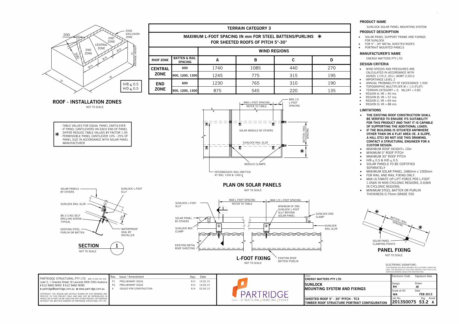
AS/NZS 1170.2: 2011 /ADMT 2:2012 IMPORTANCE LEVEL 2 ANNUAL PROBABILITY OF EXCEEDANCE 1:500 TOPOGRAPHIC MULTIPLIER M = 1.0 (FLAT) TERRAIN CATEGORY = 3; Mz,CAT = 0.83 REGION A; VR = 45 m/s REGION B; VR = 57 m/s REGION C; VR = 69 m/s REGION D; VR = 88 m/s
THE EXISTING ROOF CONSTRUCTION SHALLBE VERIFIED TO ENSURE ITS SUITABILITYFOR THIS PRODUCT AND THAT IT IS CAPABLEOF SUPPORTING THE ADDITIONAL LOADS.
IF THE BUILDING IS SITUATED ANYWHEREOTHER THAN ON A FLAT AREA (IE. A SLOPE,A HILL ETC) DO NOT USE THIS DRAWING.CONTACT A STRUCTURAL ENGINEER FOR ACUSTOM DESIGN.
MAXIMUM ROOF HEIGHT= 10m MINIMUM 5° ROOF PITCH MAXIMUM 30° ROOF PITCH H/B < 0.5 & H/D < 0.5 SOLAR PANELS TO BE CERTIFIED
SEPARATELY MAXIMUM SOLAR PANEL 1680mm x 1000mm FOR RAIL AND RAIL FIXING ONLY.
MAX ULTIMATE UP-LIFT FORCE PER L-FOOT1.05kN IN NON CYCLONIC REGIONS, 0.63kNIN CYCLONIC REGIONS.
MINIMUM STEEL BATTEN OR PURLINTHICKNESS 0.75mm GRADE 550
PRODUCT DESCRIPTION SOLAR PANEL SUPPORT FRAME AND FIXINGS
FOR SUNLOCK FOR 5° - 30° METAL SHEETED ROOFS PORTRAIT MOUNTED PANELS
A B
FOR SHEETED ROOFS OF PITCH 5°-30°
CBATTEN & RAILSPACING DROOF ZONE
MAXIMUM L-FOOT SPACING IN mm FOR STEEL BATTENS/PURLINS
WIND REGIONS
1740
1245
1230
875
1085
775
765
545
440
315
310
220
270
195
190
135
CENTRALZONE
ENDZONE 900, 1200, 1300
600
900, 1200, 1300
600
TERRAIN CATEGORY 3
- TABLE VALUES FOR EQUAL PANEL CANTILEVER- IF PANEL CANTILEVERS ON EACH END OF PANEL DIFFER REDUCE TABLE VALUES BY FACTOR 1.09- PERMISSIBLE PANEL CANTILEVER 10% - 25% OF PANEL SIZE IN ACCORDANCE WITH SOLAR PANEL MANUFACTURER
NOT TO SCALE
'D''B'
'H'
AVE
RA
GE
HE
IGH
T
ROOF - INSTALLATION ZONES
H/B < 0.5H/D < 0.5
ENDZONE
ENDZONE
CENTRALZONE
'B'/3
'B'/3
'B'/3
EDGEEXCLUSIONZONE
200
200
Rev. Issue / Amendment App. Date Electronic Code Signature Date
DrawnDesign
Scale at A3 Date
Job No. Drg. Amdt.
ELECTRONIC SIGNATURE:THIS DRAWING HAS BEEN ASSIGNED AN ELECTRONIC SIGNATURECODE. THE PRESENCE OF THIS CODE SIGNIFIES THAT THIS IS THECERTIFIED DRAWING ISSUED FOR CONSTRUCTION.
COPYRIGHT: THE DESIGN AND DETAILS SHOWN ON THIS DRAWING ARESPECIFIC TO THIS PROJECT ONLY AND MAY NOT BE REPRODUCED INWHOLE OR IN PART OR BE USED FOR ANY OTHER PROJECT OR PURPOSEWITHOUT THE WRITTEN CONSENT OF PARTRIDGE STRUCTURAL PTY LTD.
PARTRIDGE STRUCTURAL PTY LTD ABN 73 002 451 925
SUNLOCKMOUNTING SYSTEM AND FIXINGS
SHEETED ROOF 5° - 30° PITCH - TC3TIMBER ROOF STRUCTURE PORTRAIT CONFIGURATION
Client
ENERGY MATTERS PTY LTD
RH JR
N/A FEB 2013
2013S0075 S3.2 A
P1 PRELIMINARY ISSUE R.H 15.02.13
P2 PRELIMINARY ISSUE R.H 14.03.13
A ISSUED FOR CONSTRUCTION R.H 02.04.13

1-
DETAIL
EQUAL CANTILEVER 10% TO 25% OFPANEL SIZE IN ACCORDANCE WITH THESOLAR PANEL MANUFACTURER'S DETAIL
NOT TO SCALE
NOTE: SUNLOCK CHANNEL TO BE EMPLOYEDWHEN TILT ANGLE AND EXISTING PURLINSPACING DICTATE THAT REAR LEG DOES NOTCOINCIDE WITH A PURLIN
SLLF WITHØ6.3mm (14G) SELFDRILLING SCREW INTOSTEEL PURLIN/BATTEN
Ø6.3mm (14G) SELFDRILLING SCREW INTOSTEEL PURLIN/BATTEN
Ø6.3mm (14G) SELFDRILLING SCREW INTOSTEEL PURLIN/BATTEN
STEEL PURLIN/BATTEN
SUNLOCK MIDCLAMP OR ENDCLAMP
PORTRAITMOUNTED SOLARPANEL
SUNLOCK RAIL SL2R
STEEL BATTEN OR PURLIN 1300
MAX BATTEN SPACING
STEEL BATTEN OR PURLIN 1300
MAX BATTEN SPACING
ROOF SHEETING
SUNLOCK CHANNEL
EQUAL
EQUAL
SUNLOCK RAIL SL2R
SLLF WITHM8 BOLT TYPICAL
20° TO 40° TILT A
NGLE TO HORIZONTAL
WIND REGIONSHORT LEG
LONG LEGINTERNALZONE
EDGEZONE
SHORT LEG
LONG LEGZONE
SHORT LEG
LONG LEG
MAXIMUM L-FOOT SPACING IN mm FOR STEEL BATTENS/PURLINSPRODUCT NAME
MANUFACTURER'S NAME
DESIGN CRITERIA
LIMITATIONS
SUNLOCK SOLAR PANEL MOUNTING SYSTEM
ENERGY MATTERS PTY LTD
WIND SPEEDS AND PRESSURES ARECALCULATED IN ACCORDANCE WITH
AS/NZS 1170.2: 2011 IMPORTANCE LEVEL 2 ANNUAL PROBABILITY OF EXCEEDANCE 1:500 TOPOGRAPHIC MULTIPLIER M = 1.0 (FLAT) TERRAIN CATEGORY = 2; Mz,CAT = 1 REGION A; VR = 45 m/s REGION B; VR = 57 m/s REGION C; VR = 69 m/s REGION D; VR = 88 m/s
THE EXISTING ROOF CONSTRUCTION SHALLBE VERIFIED BY A SUITABLY QUALIFIEDSTRUCTURAL ENGINEER TO ENSURE THATIT CAN SUPPORT THE ADDITIONAL LOADS.
IF THE BUILDING IS SITUATED ANYWHEREOTHER THAN ON A FLAT AREA(IE. A SLOPE, A HILL ETC) DO NOT USE THISDRAWING. CONTACT A STRUCTURALENGINEER FOR A CUSTOM DESIGN.
MAXIMUM ROOF HEIGHT= 10m MAXIMUM 10° ROOF PITCH SOLAR PANELS TO BE CERTIFIED
SEPARATELY MAXIMUM SOLAR PANEL 1680mm x
1000mm MAX ULTIMATE UP-LIFT FORCE PER
FOOTING BRACKET 1.05kN IN NONCYCLONIC REGIONS, 0.63kN IN CYCLONICREGIONS.
MINIMUM STEEL BATTEN OR PURLINTHICKNESS 0.75mm GRADE 550
PRODUCT DESCRIPTION SOLAR PANEL TILTED FRAME AND FIXINGS FOR
SUNLOCK FOR 20° - 40° FRAME TILT ANGLES PORTRAIT MOUNTED PANELS
1075
655
715
435
535
325
675
410
450
275
335
205
270
165
180
110
135
85
170
105
110
70
85
50'D'
'B'
H
AVE
RA
GE
HE
IGH
T
NOT TO SCALE
'A'= MINIMUM OF 0.2 x B, 0.2 x D OR 1 x H
EDGE ZONE
INTERMEDIATEZONE
'A'
'A'2
INTERNAL ZONE
METAL SHEETED ROOF - INSTALLATION ZONES
CORNER ZONE
CORNERZONE
TERRAIN CATEGORY 2
SHORT LEG
LONG LEG
355
215
225
135
90
55
55
35
'A''A'2
'A'
'A'2
LONG LEG SPACING
DIAGONALBRACING
NOTE: PROVIDE SLDB1200 40 x 3 FLAT; ALUMINIUM DIAGONAL BRACE TOEACH END BAY
DIAGONALBRACING
NOT TO SCALE
RAIL JOINER LOCATION0.25 x LONG LEG SPACING
MAXIMUM CANTILEVER1
3 OF ADJACENT BAY
REFER TO TABLE
RAIL JOINER LOCATION0.25 x SHORT LEG SPACING
SHORT LEG SPACINGREFER TO TABLE
SUNLOCK REAR FRAMING ELEVATION
FIX FOOTING BRACKET TOCONCRETE SLAB WITH 1M10STAINLESS STEEL DYNABOLT OREQUIVALENT (WATERPROOFINGTO BUILDER'S DETAIL)
45
MIN
SCALE 1:5
70MIN
CO
NC
RE
TE E
DG
E
ALTERNATIVE CONCRETEFIXING DETAIL
Rev. Issue / Amendment App. Date Electronic Code Signature Date
DrawnDesign
Scale at A3 Date
Job No. Drg. Amdt.
ELECTRONIC SIGNATURE:THIS DRAWING HAS BEEN ASSIGNED AN ELECTRONIC SIGNATURECODE. THE PRESENCE OF THIS CODE SIGNIFIES THAT THIS IS THECERTIFIED DRAWING ISSUED FOR CONSTRUCTION.
COPYRIGHT: THE DESIGN AND DETAILS SHOWN ON THIS DRAWING ARESPECIFIC TO THIS PROJECT ONLY AND MAY NOT BE REPRODUCED INWHOLE OR IN PART OR BE USED FOR ANY OTHER PROJECT OR PURPOSEWITHOUT THE WRITTEN CONSENT OF PARTRIDGE STRUCTURAL PTY LTD.
PARTRIDGE STRUCTURAL PTY LTD ABN 73 002 451 925
SUNLOCKMOUNTING SYSTEM AND FIXINGS
SHEETED ROOF AT MAX 10° PITCH - TC2STEEL ROOF STRUCTURE PORTRAIT CONFIGURATION
Client
ENERGY MATTERS PTY LTD
RH JR
N/A FEB 2013
2013S0075 S4.1 A
P1 PRELIMINARY ISSUE R.H 15.02.13
P2 PRELIMINARY ISSUE R.H 14.03.13
A ISSUED FOR CONSTRUCTION R.H 02.04.13

EQUAL CANTILEVER 10% TO 25% OFPANEL SIZE IN ACCORDANCE WITH THESOLAR PANEL MANUFACTURER'S DETAIL
1-
DETAILNOT TO SCALE
NOTE: SUNLOCK CHANNEL TO BE EMPLOYEDWHEN TILT ANGLE AND EXISTING PURLINSPACING DICTATE THAT REAR LEG DOES NOTCOINCIDE WITH A PURLIN
SLLF WITHØ6.3mm (14G) SELFDRILLING SCREW INTOSTEEL PURLIN/BATTEN
Ø6.3mm (14G) SELFDRILLING SCREW INTOSTEEL PURLIN/BATTEN
Ø6.3mm (14G) SELFDRILLING SCREW INTOSTEEL PURLIN/BATTEN
STEEL PURLIN/BATTEN
SUNLOCK MIDCLAMP OR ENDCLAMP
PORTRAITMOUNTED SOLARPANEL
SUNLOCK RAIL SL2R
STEEL BATTEN OR PURLIN 1300MAX BATTEN SPACING
STEEL BATTEN OR PURLIN 1300MAX BATTEN SPACING
ROOF SHEETING
SUNLOCK CHANNEL
EQUAL
EQUAL
SUNLOCK RAIL SL2R
SLLF WITHM8 BOLT TYPICAL
20° TO 40° TILT A
NGLE TO HORIZONTAL
WIND REGIONSHORT LEG
LONG LEGINTERNALZONE
EDGEZONE
SHORT LEG
LONG LEGZONE
SHORT LEG
LONG LEG
1435
950
1040
635
780
475
1215
740
810
495
605
370
395
240
260
160
195
120
245
150
160
100
120
75
MAXIMUM L-FOOT SPACING IN mm FOR STEEL BATTENS/PURLINSPRODUCT NAME
MANUFACTURER'S NAME
DESIGN CRITERIA
LIMITATIONS
SUNLOCK SOLAR PANEL MOUNTING SYSTEM
ENERGY MATTERS PTY LTD
WIND SPEEDS AND PRESSURES ARECALCULATED IN ACCORDANCE WITH
AS/NZS 1170.2: 2011 IMPORTANCE LEVEL 2 ANNUAL PROBABILITY OF EXCEEDANCE 1:500 TOPOGRAPHIC MULTIPLIER M = 1.0 (FLAT) TERRAIN CATEGORY = 3; Mz,CAT = 0.83
REGION A; VR = 45 m/s REGION B; VR = 57 m/s REGION C; VR = 69 m/s REGION D; VR = 88 m/s
THE EXISTING ROOF CONSTRUCTION SHALLBE VERIFIED BY A SUITABLY QUALIFIEDSTRUCTURAL ENGINEER TO ENSURE THATIT CAN SUPPORT THE ADDITIONAL LOADS.
IF THE BUILDING IS SITUATED ANYWHEREOTHER THAN ON A FLAT AREA(IE. A SLOPE, A HILL ETC) DO NOT USE THISDRAWING. CONTACT A STRUCTURALENGINEER FOR A CUSTOM DESIGN.
MAXIMUM ROOF HEIGHT= 10m MAXIMUM 10° ROOF PITCH SOLAR PANELS TO BE CERTIFIED
SEPARATELY MAXIMUM SOLAR PANEL 1680mm x
1000mm MAX ULTIMATE UP-LIFT FORCE PER
FOOTING BRACKET 1.05kN IN NONCYCLONIC REGIONS, 0.63kN IN CYCLONICREGIONS.
MINIMUM STEEL BATTEN OR PURLINTHICKNESS 0.75mm GRADE 550
PRODUCT DESCRIPTION SOLAR PANEL TILTED FRAME AND FIXINGS FOR
SUNLOCK FOR 20° - 40° FRAME TILT ANGLES PORTRAIT MOUNTED PANELS
TERRAIN CATEGORY 3
CORNERZONE
520
315
405
245
130
80
80
50
SHORT LEG
LONG LEG
'D'
'B'
H
AVE
RA
GE
HE
IGH
T
NOT TO SCALE
'A'= MINIMUM OF 0.2 x B, 0.2 x D OR 1 x H
EDGE ZONE
INTERMEDIATEZONE
'A'
'A'2
INTERNAL ZONE
METAL SHEETED ROOF - INSTALLATION ZONES
CORNER ZONE
'A''A'2
'A'
'A'2
LONG LEG SPACING
DIAGONALBRACING
DIAGONALBRACING
NOT TO SCALE
RAIL JOINER LOCATION0.25 x LONG LEG SPACING
MAXIMUM CANTILEVER1
3 OF ADJACENT BAY
REFER TO TABLE
RAIL JOINER LOCATION0.25 x SHORT LEG SPACING
SHORT LEG SPACINGREFER TO TABLE
NOTE: PROVIDE SLDB1200 40 x 3 FLAT; ALUMINIUM DIAGONAL BRACE TOEACH END BAY
SUNLOCK REAR FRAMING ELEVATION
CO
NC
RE
TE E
DG
E
ALTERNATIVE CONCRETEFIXING DETAIL
FIX FOOTING BRACKET TOCONCRETE SLAB WITH 1M10STAINLESS STEEL DYNABOLT OREQUIVALENT (WATERPROOFINGTO BUILDER'S DETAIL)
45
MIN
70MIN
SCALE 1:5
Rev. Issue / Amendment App. Date Electronic Code Signature Date
DrawnDesign
Scale at A3 Date
Job No. Drg. Amdt.
ELECTRONIC SIGNATURE:THIS DRAWING HAS BEEN ASSIGNED AN ELECTRONIC SIGNATURECODE. THE PRESENCE OF THIS CODE SIGNIFIES THAT THIS IS THECERTIFIED DRAWING ISSUED FOR CONSTRUCTION.
COPYRIGHT: THE DESIGN AND DETAILS SHOWN ON THIS DRAWING ARESPECIFIC TO THIS PROJECT ONLY AND MAY NOT BE REPRODUCED INWHOLE OR IN PART OR BE USED FOR ANY OTHER PROJECT OR PURPOSEWITHOUT THE WRITTEN CONSENT OF PARTRIDGE STRUCTURAL PTY LTD.
PARTRIDGE STRUCTURAL PTY LTD ABN 73 002 451 925
SUNLOCKMOUNTING SYSTEM AND FIXINGS
SHEETED ROOF AT MAX 10° PITCH - TC3STEEL ROOF STRUCTURE PORTRAIT CONFIGURATION
Client
ENERGY MATTERS PTY LTD
RH JR
N/A FEB 2013
2013S0075 S4.2 A
P1 PRELIMINARY ISSUE R.H 15.02.13
P2 PRELIMINARY ISSUE R.H 14.03.13
A ISSUED FOR CONSTRUCTION R.H 02.04.13

EQUAL CANTILEVER 10% TO 25% OFPANEL SIZE IN ACCORDANCE WITH THESOLAR PANEL MANUFACTURER'S DETAIL
SUNLOCK MID CLAMPOR END CLAMP
PORTRAIT MOUNTEDSOLAR PANEL
20° TO 40° TILT A
NGLE TO HORIZONTAL
SUNLOCK RAIL SL2R
SLLF WITHM8 BOLT TYPICAL
TIMBER BATTEN OR PURLIN 1300MAX BATTEN SPACING
TIMBER BATTEN OR PURLIN 1300MAX BATTEN SPACING
TIMBER PURLIN/BATTEN ROOF SHEETING Ø6.3mm (14G) TIMBERSCREW. 35mm INTO TIMBERPURLIN/ BATTEN
SUNLOCK CHANNEL
Ø6.3mm (14G)TIMBER SCREW35mm INTOSTEEL PURLIN/BATTEN
SLLF WITHØ6.3mm (14G) TIMBER SCREW35mm INTOSTEEL PURLIN/BATTEN
SLLF WITHØ6.3mm (14G) TIMBER SCREW35mm INTOSTEEL PURLIN/BATTEN
EQUAL
EQUAL
1-
DETAILNOT TO SCALE
NOTE: SUNLOCK CHANNEL TO BEEMPLOYED WHEN TILT ANGLE ANDEXISTING PURLIN SPACING DICTATETHAT REAR LEG DOES NOT COINCIDEWITH A PURLIN
SUNLOCK RAIL SL2R
PRODUCT NAME
MANUFACTURER'S NAME
DESIGN CRITERIA
LIMITATIONS
SUNLOCK SOLAR PANEL MOUNTING SYSTEM
ENERGY MATTERS PTY LTD
WIND SPEEDS AND PRESSURES ARECALCULATED IN ACCORDANCE WITHAS/NZS 1170.2: 2011
IMPORTANCE LEVEL 2 ANNUAL PROBABILITY OF EXCEEDANCE 1:500 TOPOGRAPHIC MULTIPLIER M = 1.0 (FLAT) TERRAIN CATEGORY = 2; Mz,CAT = 1.0 REGION A; VR = 45 m/s REGION B; VR = 57 m/s REGION C; VR = 69 m/s REGION D; VR = 88 m/s
THE EXISTING ROOF CONSTRUCTION SHALLBE VERIFIED BY A SUITABLY QUALIFIEDSTRUCTURAL ENGINEER TO ENSURE THAT ITCAN SUPPORT THE ADDITIONAL LOADS.
IF THE BUILDING IS SITUATED ANYWHEREOTHER THAN ON A FLAT AREA (IE. A SLOPE, AHILL ETC) DO NOT USE THIS DRAWING.CONTACT A STRUCTURAL ENGINEER FOR ACUSTOM DESIGN.
MAXIMUM ROOF HEIGHT= 10m MAXIMUM 10° ROOF PITCH SOLAR PANELS TO BE CERTIFIED
SEPARATELY MAXIMUM SOLAR PANEL 1680mm x 1000mm MAX ULTIMATE UP-LIFT FORCE PER FOOTING
BRACKET 1.6kN TIMBER BATTENS OR PURLINS TO SUPPORT
FRAME TO BE JOINT GROUP J4 OR BETTER
PRODUCT DESCRIPTION
SOLAR PANEL TILTED FRAME AND FIXINGSFOR SUNLOCK
FOR 20° - 40° FRAME TILT ANGLES PORTRAIT MOUNTED PANELS
WIND REGIONSHORT LEG
LONG LEGINTERNALZONE
EDGEZONE
SHORT LEG
LONG LEGZONE
SHORT LEG
LONG LEG
1270
1000
1090
665
820
500
1025
625
685
415
510
310
690
420
460
280
345
210
430
260
285
175
215
130
CORNERZONE
SHORT LEG
LONG LEG
MAXIMUM L-FOOT SPACING IN mm FOR TIMBER BATTENS/PURLINS - TC 2TERRAIN CATEGORY 2
545
330
340
205
230
140
140
85
'D'
'B'
H
AVE
RA
GE
HE
IGH
T
NOT TO SCALE
'A'= MINIMUM OF 0.2 x B, 0.2 x D OR 1 x H
EDGE ZONE
INTERMEDIATEZONE
'A'
'A'2
INTERNAL ZONE
METAL SHEETED ROOF - INSTALLATION ZONES
CORNER ZONE
'A''A'2
'A'
'A'2
LONG LEG SPACING
DIAGONALBRACING
DIAGONALBRACING
RAIL JOINER LOCATION0.25 x LONG LEG SPACING
MAXIMUM CANTILEVER1
3 OF ADJACENT BAY
REFER TO TABLE
RAIL JOINER LOCATION0.25 x SHORT LEG SPACING
SHORT LEG SPACINGREFER TO TABLE
NOTE: PROVIDE SLDB1200 40 x 3 FLAT; ALUMINIUM DIAGONAL BRACE TOEACH END BAY
NOT TO SCALE
SUNLOCK REAR FRAMING ELEVATION
CO
NC
RE
TE E
DG
E
ALTERNATIVE CONCRETEFIXING DETAIL
FIX FOOTING BRACKET TOCONCRETE SLAB WITH 1M10STAINLESS STEEL DYNABOLT OREQUIVALENT (WATERPROOFINGTO BUILDER'S DETAIL)
45
MIN
70MIN
SCALE 1:5
Rev. Issue / Amendment App. Date Electronic Code Signature Date
DrawnDesign
Scale at A3 Date
Job No. Drg. Amdt.
ELECTRONIC SIGNATURE:THIS DRAWING HAS BEEN ASSIGNED AN ELECTRONIC SIGNATURECODE. THE PRESENCE OF THIS CODE SIGNIFIES THAT THIS IS THECERTIFIED DRAWING ISSUED FOR CONSTRUCTION.
COPYRIGHT: THE DESIGN AND DETAILS SHOWN ON THIS DRAWING ARESPECIFIC TO THIS PROJECT ONLY AND MAY NOT BE REPRODUCED INWHOLE OR IN PART OR BE USED FOR ANY OTHER PROJECT OR PURPOSEWITHOUT THE WRITTEN CONSENT OF PARTRIDGE STRUCTURAL PTY LTD.
PARTRIDGE STRUCTURAL PTY LTD ABN 73 002 451 925
SUNLOCKMOUNTING SYSTEM AND FIXINGS
SHEETED ROOF AT MAX 10° PITCH - TC2TIMBER ROOF STRUCTURE PORTRAIT CONFIGURATION
Client
ENERGY MATTERS PTY LTD
RH JR
N/A FEB 2013
2013S0075 S5.1 A
P1 PRELIMINARY ISSUE R.H 15.02.13
P2 PRELIMINARY ISSUE R.H 14.03.13
A ISSUED FOR CONSTRUCTION R.H 02.04.13

EQUAL CANTILEVER 10% TO 25% OFPANEL SIZE IN ACCORDANCE WITH THESOLAR PANEL MANUFACTURER'S DETAIL
SUNLOCK MID CLAMPOR END CLAMP
PORTRAIT MOUNTEDSOLAR PANEL
20° TO 40° TILT A
NGLE TO HORIZONTAL
SUNLOCK RAIL SL2R
SLLF WITHM8 BOLT TYPICAL
TIMBER BATTEN OR PURLIN 1300MAX BATTEN SPACING
TIMBER BATTEN OR PURLIN 1300MAX BATTEN SPACING
TIMBER PURLIN/BATTEN ROOF SHEETING Ø6.3mm (14G) TIMBERSCREW. 35mm INTO TIMBERPURLIN/ BATTEN
SUNLOCK CHANNEL
Ø6.3mm (14G)TIMBER SCREW35mm INTOSTEEL PURLIN/BATTEN
SLLF WITHØ6.3mm (14G) TIMBER SCREW35mm INTOSTEEL PURLIN/BATTEN
SLLF WITHØ6.3mm (14G) TIMBER SCREW35mm INTOSTEEL PURLIN/BATTEN
EQUAL
EQUAL
1-
DETAILNOT TO SCALE
NOTE: SUNLOCK CHANNEL TO BEEMPLOYED WHEN TILT ANGLE ANDEXISTING PURLIN SPACING DICTATETHAT REAR LEG DOES NOT COINCIDEWITH A PURLIN
SUNLOCK RAIL SL2R
PRODUCT NAME
MANUFACTURER'S NAME
DESIGN CRITERIA
LIMITATIONS
SUNLOCK SOLAR PANEL MOUNTING SYSTEM
ENERGY MATTERS PTY LTD
WIND SPEEDS AND PRESSURES ARECALCULATED IN ACCORDANCE WITHAS/NZS 1170.2: 2011
IMPORTANCE LEVEL 2 ANNUAL PROBABILITY OF EXCEEDANCE 1:500 TOPOGRAPHIC MULTIPLIER M = 1.0 (FLAT) TERRAIN CATEGORY = 3; Mz,CAT = 0.83 REGION A; VR = 45 m/s REGION B; VR = 57 m/s REGION C; VR = 69 m/s REGION D; VR = 88 m/s
THE EXISTING ROOF CONSTRUCTION SHALLBE VERIFIED BY A SUITABLY QUALIFIEDSTRUCTURAL ENGINEER TO ENSURE THATIT CAN SUPPORT THE ADDITIONAL LOADS.
IF THE BUILDING IS SITUATED ANYWHEREOTHER THAN ON A FLAT AREA (IE. A SLOPE,A HILL ETC) DO NOT USE THIS DRAWING.CONTACT A STRUCTURAL ENGINEER FOR ACUSTOM DESIGN.
MAXIMUM ROOF HEIGHT= 10m MAXIMUM 10° ROOF PITCH SOLAR PANELS TO BE CERTIFIED
SEPARATELY MAXIMUM SOLAR PANEL 1680mm x 1000mm MAX ULTIMATE UP-LIFT FORCE PER FOOTING
BRACKET 1.6kN TIMBER BATTENS OR PURLINS TO SUPPORT
FRAME TO BE JOINT GROUP J4 OR BETTER
PRODUCT DESCRIPTION
SOLAR PANEL TILTED FRAME AND FIXINGSFOR SUNLOCK
FOR 20° - 40° FRAME TILT ANGLES PORTRAIT MOUNTED PANELS
WIND REGIONSHORT LEG
LONG LEGINTERNALZONE
EDGEZONE
SHORT LEG
LONG LEGZONE
SHORT LEG
LONG LEG
1295
1255
970
1140
725
1410
1130
1235
750
925
565
1005
610
670
410
500
305
620
380
415
250
310
190
MAXIMUM L-FOOT SPACING IN mm FOR TIMBER BATTENS/PURLINS
1440
CORNERZONE
SHORT LEG
LONG LEG
TERRAIN CATEGORY 3
790
485
615
375
335
205
205
125
'D'
'B'
H
AVE
RA
GE
HE
IGH
T
NOT TO SCALE
'A'= MINIMUM OF 0.2 x B, 0.2 x D OR 1 x H
EDGE ZONE
INTERMEDIATEZONE
'A'
'A'2
INTERNAL ZONE
METAL SHEETED ROOF - INSTALLATION ZONES
CORNER ZONE
'A''A'2
'A'
'A'2
LONG LEG SPACING
DIAGONALBRACING
NOTE: PROVIDE SLDB1200 40 x 3 FLAT; ALUMINIUM DIAGONAL BRACE TOEACH END BAY
DIAGONALBRACING
NOT TO SCALE
RAIL JOINER LOCATION0.25 x LONG LEG SPACING
MAXIMUM CANTILEVER1
3 OF ADJACENT BAY
REFER TO TABLE
RAIL JOINER LOCATION0.25 x SHORT LEG SPACING
SHORT LEG SPACINGREFER TO TABLE
SUNLOCK REAR FRAMING ELEVATION
CO
NC
RE
TE E
DG
E
ALTERNATIVE CONCRETEFIXING DETAIL
FIX FOOTING BRACKET TOCONCRETE SLAB WITH 1M10STAINLESS STEEL DYNABOLT OREQUIVALENT (WATERPROOFINGTO BUILDER'S DETAIL)
45
MIN
70
MIN
SCALE 1:5
Rev. Issue / Amendment App. Date Electronic Code Signature Date
DrawnDesign
Scale at A3 Date
Job No. Drg. Amdt.
ELECTRONIC SIGNATURE:THIS DRAWING HAS BEEN ASSIGNED AN ELECTRONIC SIGNATURECODE. THE PRESENCE OF THIS CODE SIGNIFIES THAT THIS IS THECERTIFIED DRAWING ISSUED FOR CONSTRUCTION.
COPYRIGHT: THE DESIGN AND DETAILS SHOWN ON THIS DRAWING ARESPECIFIC TO THIS PROJECT ONLY AND MAY NOT BE REPRODUCED INWHOLE OR IN PART OR BE USED FOR ANY OTHER PROJECT OR PURPOSEWITHOUT THE WRITTEN CONSENT OF PARTRIDGE STRUCTURAL PTY LTD.
PARTRIDGE STRUCTURAL PTY LTD ABN 73 002 451 925
SUNLOCKMOUNTING SYSTEM AND FIXINGS
SHEETED ROOF AT MAX 10° PITCH - TC3TIMBER ROOF STRUCTURE PORTRAIT CONFIGURATION
Client
ENERGY MATTERS PTY LTD
RH JR
N/A FEB 2013
2013S0075 S5.2 A
P1 PRELIMINARY ISSUE R.H 15.02.13
P2 PRELIMINARY ISSUE R.H 14.03.13
A ISSUED FOR CONSTRUCTION R.H 02.04.13