romanstack the solid choice - concrete patio pavers · • advanced software is available to help...
TRANSCRIPT

The
So
lid C
hoic
ePisaStone
Pisa2
RomanPisa
StackStone
Split'nStack
RomanStack
SienaStone
VeronaStone
DuraHold
DuraHold2
®
®
PisaStone
Pisa2
RomanPisa
StackStone
Split'nStack
RomanStack
SienaStone
VeronaStone
DuraHold
DuraHold2
®
®
/ Design Manual

Pisa2® and Roman Pisa® Design Manual
RisiStoneretaining wall systems
Pisa2
WRITTEN & ILLUSTRATED BY: Robert Bowers, P.ENG
Eric Jonasson, E.I.T.Claudia Yun Kang, B.ENG
Tyler Matys, P.ENG
Mark Risi Allison Uher

Risi Stone Systems8500 Leslie Street, Suite 390Thornhill, ON L3T 7M8 Canada© 2004 by Risi Stone SystemsAll rights reserved. Published 2004Printed in Canada
Risi Stone Systems has attempted to ensure that all information contained in this guide is correct. However, there is the possibility that this guide may contain errors. Review all designs with your local sales representative prior to construction. Final determination of the suitability of any information or material is the sole responsibility of the user.
RisiStoneretaining wall systems
Toll-free: 1-800-626-WALL (9255)Fax: 905-882-4556Email: [email protected]: www.risistone.com

INTRODUCTION The Pisa2 and RomanPisa System . . . . . . . . . . . . . . . . . . . . . . . . . . . . . . . . . . . . . . . . . . . . . . . .1
Design Methodology . . . . . . . . . . . . . . . . . . . . . . . . . . . . . . . . . . . . . . . . . . . . . . . . . . . . . . . . . . . . . . . . . . . 4
Soils . . . . . . . . . . . . . . . . . . . . . . . . . . . . . . . . . . . . . . . . . . . . . . . . . . . . . . . . . . . . . . . . . . . . . . . . . . . . . . . . . . . . . . . . . . . 6
Geogrid Reinforcement . . . . . . . . . . . . . . . . . . . . . . . . . . . . . . . . . . . . . . . . . . . . . . . . . . . . . . . . . . . . . . . . 8
CONVENTIONAL SEGMENTAL RETAINING WALL DESIGN
Conventional Design Methodology . . . . . . . . . . . . . . . . . . . . . . . . . . . . . . . . . . . . . . . . . . . . . . . . 9
External Stability Calculations and Analyses . . . . . . . . . . . . . . . . . . . . . . . . . . . . . . . . . 10
REINFORCED SEGMENTAL RETAINING WALL DESIGN
Reinforced Design Methodology . . . . . . . . . . . . . . . . . . . . . . . . . . . . . . . . . . . . . . . . . . . . . . . . . 15
Hinge Height . . . . . . . . . . . . . . . . . . . . . . . . . . . . . . . . . . . . . . . . . . . . . . . . . . . . . . . . . . . . . . . . . . . . . . . . . . . . . 17
External Stability Calculations and Analyses . . . . . . . . . . . . . . . . . . . . . . . . . . . . . . . . . 18
Internal Stability Calculations and Analyses . . . . . . . . . . . . . . . . . . . . . . . . . . . . . . . . . . 19
Local Stability Calculations and Analyses . . . . . . . . . . . . . . . . . . . . . . . . . . . . . . . . . . . . . 25
SPECIAL DESIGN CONDITIONS
Other Structures . . . . . . . . . . . . . . . . . . . . . . . . . . . . . . . . . . . . . . . . . . . . . . . . . . . . . . . . . . . . . . . . . . . . . . . . 31
Terraced Walls . . . . . . . . . . . . . . . . . . . . . . . . . . . . . . . . . . . . . . . . . . . . . . . . . . . . . . . . . . . . . . . . . . . . . . . . . . 34
Water Applications . . . . . . . . . . . . . . . . . . . . . . . . . . . . . . . . . . . . . . . . . . . . . . . . . . . . . . . . . . . . . . . . . . . . 35
contentsRisiStoneretaining wall systems

Pisa2® / RomanPisa® Design Manual ©2004 Risi Stone Systems
introd
uction
RisiStoneretaining wall systems
Pisa2® / RomanPisa® Design Manual ©2004 Risi Stone Systems
intr
od
ucti
on
the Pisa2® and RomanPisa® system
For the duration of this book, “Pisa2” will be used to refer to both the Pisa2 and RomanPisa systems unless otherwise specified.
The Pisa2 system is a solid, modular concrete retaining wall system that is used to stabilize and contain earth embankments, large or small. The Pisa2 system is based on the principles and designs of the PisaStone system developed in 1970. Over the next 15 years, hundreds of successful installations were completed. During this period the requirements of designers, installers and owners were further refined and identified. These needs led to the evolution of the Pisa2 system. Today, the Pisa2 system and several other retaining wall systems licensed by Risi Stone Systems are manufactured and installed across North America and internationally.
In the Pisa2 system, the majority of the facing is constructed from a single mass-produced modular unit. Because the units are solid, they can easily be modified by scoring and splitting. Specialized units are available to help speed the installation of wall features like coping, curves, corners, lights, and audio speakers. The Pisa2 system can be constructed in two basic configurations: a Pisa2 Conventional SRW or a Pisa2 Geogrid Reinforced SRW.
There are many applications for Pisa2 retaining walls. Most examples can be divided into the two aforementioned configurations which, more or less, follow two basic uses: landscape applications and structural applications.
In landscape applications, the primary purpose of retaining walls is aesthetic in nature. Some examples of Pisa2 landscape uses are planters, driveway edging, steps, tree wells, and smaller garden retaining walls. Most landscape applications call for walls under 1.0 m (3 ft) in height, with minimal loads being applied to the wall. Consequently, most landscape walls are built as conventional SRWs.
In structural applications, the primary function of retaining walls is to provide structure and strength to steep slopes or cuts. Some common structural uses for Pisa2 retaining walls are high walls, some in excess of 7.5 m (25 ft); walls required to support parking, roads, or highways; and erosion protection along streams or lakes. In all of these cases, geosynthetic reinforcement is used.
The Pisa2 system is supported by the local maufacturers and Risi Stone Systems. Local manufacturers will make every attempt to answer your general questions and they will gladly provide customers with answers for site-spe-cific applications. Each manufacturer has access to prepared information on the Pisa2 system and has plenty of experience installing it. The RisiWall design software also helps to provide solutions for specific site designs. Unique applications often necessitate the assistance of a professional engineer. Risi Stone Systems can provide these so-lutions through its Engineering Design Assistance program. The Pisa2 system has a number of features that make the system unique. Each of these features has been developed to give a Pisa2 retaining wall the advantages of in-creased beauty, simplified installation, and greater strength. These features benefit the owner by lowering the entire cost of the retaining wall, both during installation and well into the future.
features • advantages • benefitsModular Retaining Wall SystemWall is flexible, yet retains its structural characteristics. • The wall can absorb minor movements due to frost or settlement. • Requires minimal embedment below grade.
A compacted granular base is all that is required. • Reduces the cost by not requiring an expensive structural footing.
1

Pisa2® / RomanPisa® Design Manual ©2004 Risi Stone Systems
introd
uction
RisiStoneretaining wall systems
Pisa2® / RomanPisa® Design Manual ©2004 Risi Stone Systems
intr
od
ucti
on
Solid Unit Manufactured From 35 MPA (5000 PSI) ConcreteProvides wall with greater durability. • Ensures the maximum weight of each unit because there are no voids or cores to be filled. • Less susceptible to freeze-thaw deterioration. • Less likely to be broken by handling or in transit.
Solid units are easy to split and modify. • Can easily create site-specific features using the modular units.
No hollows to be filled with gravel and compacted. • Ensures maximum resistance to overturning forces. • Saves time and money.
Tongue and Groove InterlockInterlocking mechanism molded into the units so there are no separate pins or clips. • No need to fiddle with multiple pieces; installation rates increase. • Ensures maximum shear connection between units.
Units are dry-stacked. • Lower costs because no mortar is used in the construction. • Minimal training is required to achieve excellent installation results.
Units are self-aligning and self-battering. • Once the first course is laid flat and levelled, thereis no need for continual measuring and adjusting.
Creates a continuous interlock throughout the wall face. • Makes a stronger, more damage-resistant wall.
Size and WeightThe 19 kg (45 lb) units are well-balanced, easy to handle, and have a molded finger hold. • Units can be held by a single person for quickerinstallation.
Manufacturing method ensures a uniform height for each unit. • Courses remain at fixed elevations and should not require shimming.
Split On SiteFace of units is protected before installation. • Reduces the number of rejected units on site.
Broken aggregate is revealed on the face because the concrete has longer to cure. • The aesthetic qualities are improved by the natural stone in the face. • Creates a truly craftsman-like finish.
Pisa2 with Geogrid ReinforcementAbility to construct higher walls. • Can utilize site soil to infill the geogrids, consequently lowering disposal and extra material charges. • Can use the same facia throughout a site on lower conventional SRWs and higher geogrid reinforced SRWs.
ReversaCap or PisaStone CopingProvides a choice of coping stones for various wall arrangements. • Coping can be selected to meet site requirements (based on availability).
90º Corner UnitsManufactured to speed construction. • Offers a finished appearance to the wall. • Initiates the correct running bond pattern. • Increases the strength of corners. • Saves time during installation.
2

Pisa2® / RomanPisa® Design Manual ©2004 Risi Stone Systems
introd
uction
Pisa2® / RomanPisa® Design Manual ©2004 Risi Stone Systems
intr
od
ucti
on
RisiStoneretaining wall systems
RisiLights and RisiSoundsProvide illumination for stairs or landscape accents; blend into the wall during daylight. • Units are shipped as kits available for 110V and 12V applications. • Easy to install.
Provides an audio speaker system that blends into the wall.• Units are shipped preassembled and only require connection to the audio source.• Easy to install.
Complementing AccessoriesAll the standard features for retaining walls can be supplied by the manufacturer.• Saves time during installation.• Creates a uniform, finished look for the wall.
Technical Support and Engineering Design AssistanceTechnical expertise developed over thirty years through experience and testing is available to customers.• Ensures that retaining walls are correctly designed and constructed.• Advanced software is available to help designers generate stable retaining wall structures.
3

Pisa2® / RomanPisa® Design Manual ©2004 Risi Stone Systems
introd
uction
Pisa2® / RomanPisa® Design Manual ©2004 Risi Stone Systems
intr
od
ucti
on
RisiStoneretaining wall systems design methodology
The design methodology followed by Risi Stone Systems is based on the National Concrete Masonry Design Manual for Segmental Retaining Walls, Second Edition (hereafter referred to as the NCMA Manual). These guide-lines were specifically established for concrete faced mechanically stabilized earth walls and are the most widely accepted method in use today (visit www.ncma.org).
This document outlines the National Concrete Masonry Association (NCMA) design methodology as it applies to the Pisa2 Segmental Retaining Wall System, as well as addressing some additional design issues. This methodology an-alyzes the external, internal, and local stability of both conventional and reinforced Pisa2 segmental retaining walls.
earth pressure theoryThe NCMA methodology calculates applied earth forces on conventional and reinforced soil structures using the Coulomb earth pressure theory. Refer to Section 3.4.5 of the NCMA Manual for the rationale for choosing this method of analysis and discussion of the theory’s basic assumptions.
factor of safety methodIn accordance with the NCMA guidelines, we employ the Factor of Safety method when determining the required resistance of a Pisa2 structure. The Factor of Safety method ensures that the ratio of the unfactored stabilizing forc-es to the unfactored destabilizing forces exceeds a prescribed amount. This method has been traditionally used in geotechnical engineering to provide an acceptable margin of safety.
limit states designIn recent years there has been a trend towards the use of reliability concepts in engineering1. It has been argued that the Limit States Design approach, traditionally used in structural design, should also be applied to geotechnical engineering and the design of soil structures. The point is made that the use of load factors and resistance factors better model the various sources of uncertainties involved in the design process and facilitate a greater degree of compatibility between the geotechnical and structural design codes. Although we agree with these ideas, we have chosen to maintain the current NCMA approach described above. We will follow future developments in the NCMA methodology and/or newly adopted approaches to risk and will reflect any widely accepted industry changes in future versions of the Pisa2 Design Manual.
Although the following methodology applies the traditional Factor of Safety approach, the equations provided for unfactored applied and resisting loads can still be utilized in a Limit States Design analysis if desired by applying the appropriate load and resistance factors to the calculated values.
Not included in this document are details of the calculations required to ensure GLOBAL stability of the structure. The general stability of the structure must be evaluated to ensure that the facia structure does not result in failure along slip surfaces passing beyond the boundaries of the retaining wall or partially through the infill. It is also important to asses the settlement potential of the foundation soil before construction begins. Finally, the recommendations contained in this document are restricted to the case where the ground water table is located well below the base of the reinforced soil mass. Therefore, the influence of pore water pressure is not a concern in the calculation steps outlined in the following text.
1. Canadian Geotechnical Society, Technical Committee on Foundations. Canadian Foundation Engineering Manual, Third Edition. (1992): 512.
4

Pisa2® / RomanPisa® Design Manual ©2004 Risi Stone Systems
introd
uction
Pisa2® / RomanPisa® Design Manual ©2004 Risi Stone Systems
intr
od
ucti
on
RisiStoneretaining wall systems
design assumptionsThe reinforced SRW analysis methods described are based upon the following assumptions and conditions:
1. Surcharge loads applied at the top of the wall are uniform and transient.
2. Surface and subsurface drainage is provided to prevent the development of hydrostatic pressures at the back of the wall facia and the reinforced soil zone.
3. Effective stress parameters are used for the internal friction angles of the wall infill, retained and foundation soils. The groundwater table is assumed to be well below the reinforced zone.
4. Soil unit weights are moist unit weights that include the weight of water in the soil.
5. The long-term design strength of the geogrid reinforcement has been established using appropriate factors of safety for creep reduction, construction damage, biological and chemical degradation.
6. Seismic loading is not considered.
7. Global stability has been evaluated and found to be acceptable by a qualified geotechnical engineer.
8. Foundation settlement has been evaluated and found to be acceptable by a qualified geotechnical engineer.
5

Pisa2® / RomanPisa® Design Manual ©2004 Risi Stone Systems
introd
uction
Pisa2® / RomanPisa® Design Manual ©2004 Risi Stone Systems
intr
od
ucti
on
RisiStoneretaining wall systems soils
The type of soils within and adjacent to the Pisa2 SRW will have a significant effect on the final design of the wall. From an analysis perspective, the Pisa2 methodology characterizes soils with two parameters: Internal Friction Angle and Unit Weight.
The internal friction angle of a soil is a value (in degrees) that represents the shear resistance of a soil, or, the strength of a soil. The higher the internal friction angle, the greater the shear resistance, and the lower the result-ing lateral earth pressure. Soils such as course-grained granular materials (GW, GM, GP) have high internal friction angles due to their size, shape, and orientation (usually in the range of 30° - 40°). In contrast, fine-grained soils such as silts and clays have lower internal friction angles (usually in the range of between 26° - 30°) for the same reasons. Fine-grained soils also exhibit a strength parameter known as cohesion which is a function of the water content in the soil and the electrochemical attraction between particles. For this design methodology, the cohesion term for all representative soils with the exception of the foundation soils is ignored for design. This assumption simplifies calculations and results in conservative designs.
The unit weight of the soils is the saturated unit weight. The greater the unit weight, the more pressure is exerted from both an applied and resisting perspective.
conventional wallsThere are essentially two design soil zones in a Pisa2 Conventional SRW. These are the Foundation Soil Zone, that soil supporting the wall beneath the granular footing, and the Retained Soil Zone, that soil acting on the back of the Pisa2 units and drainage layer. As discussed above, the quality (represented by the internal friction angle) of the soil in these zones will greatly influence the maximum allowable height of the conventional Pisa2 Wall. The retained and foundation soils must be either undisturbed native material or engineered fill placed and compacted to 95% SPD.
The drainage layer is a 300mm (12in) thick (minimum) layer of free-draining 19mm (3⁄4in) angular clear stone. The drainage material must be separated from the native/retained mate-rial by an approved filter fabric (completely encapsulated as shown) to prevent the migration of fines.
The footing or base of the wall should be composed of a well-graded, free-draining (max. 8% fines) granular mate-rial with a maximum particle size equal to 19mm (3⁄4in) compacted to 98% SPD. The base should extend (level) a minimum of 150mm (6in) in front and behind the Pisa2 base course. The depth of the base should be a minimum of 150mm (6in) or as required to reach competent foundation soil.
geogrid reinforced wallsThere are three design soil zones in a geogrid reinforced Pisa2 SRW. As with the conventional Pisa2 wall, the Foundation Soil Zone is that material beneath the footing and reinforced zone. The Retained Soil Zone is that ma-terial behind the reinforced zone. Finally, the Infill Soil Zone is that material compacted within the geogrid reinforced zone of the Pisa2 Wall. While the retained and foundation soils are either native materials that already exist on site or an engineered fill, the Infill Material is specifically chosen by the designer and plays a significant role in the overall design, construction, and long-term performance of the wall.
6
Retained Soil
FoundationSoil

Pisa2® / RomanPisa® Design Manual ©2004 Risi Stone Systems
introd
uction
Pisa2® / RomanPisa® Design Manual ©2004 Risi Stone Systems
intr
od
ucti
on
RisiStoneretaining wall systems
infill materialRisi Stone Systems recommends using a well-graded, free-draining (max. 8% fines), granular material to construct the reinforced zone of a Pisa2 geogrid reinforced wall. Using an imported granular infill material provides the follow-ing benefits over an approved native (fine-grained) soil:
1. Granular materials are easier to place and compact (especially in poor weather conditions).
2. Have higher permeabilities than fine-grained soils which improves overall drainage.
3. Have greater shear strength than fine-grained soils and maintain this strength under variable moisture conditions.
4. Are generally less susceptible to creep.
However, native materials that have been approved by the Design Engineer may be used in the construction of the reinforced zone. Fine-grained soils (greater than 50% fines) with low plasticity (i.e. SC, ML, CL with PI<20) may be used for infill construction. While these materials may be initially cheaper to source, other cost and performance-related considerations must be kept in mind when deciding to use them.
As fine-grained soils are not free draining, an additional clear stone drainage layer must be constructed immediately behind the facing of the wall. This drainage layer, composed of 300 mm (12 in) of free-draining 19mm (3⁄4in) angu-lar clear stone, is required to be completely encapsulated with an approved filter fabric to prevent contamination from the fine-grained infill soils. As a result, the filter fabric must be cut at each layer of geogrid and folded back (min.150 mm [6 in]) horizontally under the grid. This process is both time-consuming and increases the potential for contractor error. As well, fine-grained soils will generally require significantly more on-site monitoring by the Site Geotechnical Engineer to ensure the minimum level of quality is being consistently met throughout the structure. Finally, due lower shear strength generally means increased geogrid reinforcement requirements. All of these factors should be considered when comparing the infill options and related costs.
Imported Infill Material Native Infill Material (with drainage layer)
7

Pisa2® / RomanPisa® Design Manual ©2004 Risi Stone Systems
introd
uction
Pisa2® / RomanPisa® Design Manual ©2004 Risi Stone Systems
intr
od
ucti
on
RisiStoneretaining wall systems geogrid reinforcement
The Pisa2 Segmental Retaining Wall System can be constructed to greater heights by incorporating layers of geogrid reinforcement. The high-strength geogrid reinforcement layers integrate with the Pisa2 facing through a combination mechanical/frictional connection. The reinforcement layers combine with the Pisa2 facing and the infill soil (reinforced soil) to create a composite reinforced mass.
Although many types of geogrid reinforcement exist on the market, the Pisa2 System is only compatible with high-strength polyester geogrids. Geogrid reinforcements have two main features with regard to design.
Long Term Design Strength – This refers to the tensile capacity of the geogrid reinforcement after the necessary reduction factors have been applied to account for uncertainties in the material and environment.
Connection Capacity – This refers to the available connection capacity between the Pisa2 SRW units and the geogrid reinforcement.
long term design strengthThe Long Term Design Strength (LTDS) of a geosynthetic reinforcement is strength at limit equilibrium conditions in the soil. The LTDS is defined as the strength in the geosynthetic reinforcement at the end of the service life of a re-inforced-soil SRW, at which time all design criteria must be met for the structure to perform as intended. Polymeric reinforcements are generally durable materials that will perform for the life of the structure when properly designed. The considerations that are important in evaluating the long-term performance of the reinforcement are degradation due to physiochemical activity in the soil such as hydrolysis, oxidation, and environmental stress cracking; installa-tion damage; and the effects of high temperatures at the facing and connections of SRWs. Because of the varying polymer types, quality, additives, product geometry, and manufacturing processes, each geosynthetic is different in its resistance to aging. Each product must, therefore, be evaluated individually.
The LTDS is determined as follows:
Eq. 3-20Where:Tult = ultimate (or yield strength) from wide-width tensile strength tests (ASTM D4595 or GRI “GG1:Single Rib Geogrid Tensile Strength”), based on minimum average roll value (MARV) for the product.
RFD = Durability reduction factor. It is dependent on the susceptibility of the geosynthetic to attack by microorgan- isms, chemicals, thermal oxidations, hydrolysis, and stress cracking. The typical range is from 1.1 to 2.0.
RFID = Installation damage reduction factor. It can range from 1.05 to 3.0, depending on backfill gradation and prod- uct mass per unit weight.
RFCR = Creep reduction factor is the ratio of the ultimate strength (Tult) to the creep limit strength obtained from laboratory creep tests for each product, and can vary typically from 1.5 to 5.0.
connection capacityTo ensure accurate modelling of the connection capacity between the Pisa2 units and various different types of polyester reinforcements, Risi Stone Systems has retained the services of Bathurst, Clarabut and Associates Geotechnical Testing and NCMA Laboratory Testing to conduct full scale connection tests in accordance with NCMA standards and ASTM test procedures. This extensive connection testing program has spanned over 15 years and has yielded the necessary data to accurately characterize the specific connection capacity available between the Pisa2 SRW System and various widely available geogrid reinforcements. Connection values are included in the RisiWall Design Software.
LTDST
RF RF RFnult n
D n ID n CR n( )
( )
( ) ( ) ( )
=
8

Pisa2® / RomanPisa® Design Manual ©2004 Risi Stone Systems
RisiStoneretaining wall systems
conventio
nal
Pisa2® / RomanPisa® Design Manual ©2004 Risi Stone Systems
RisiStoneretaining wall systems
conv
enti
ona
l
conventional design methodology
Conventional Pisa2 segmental retaining walls can range in height from 0.15 m (0.5 ft) to approximately 1.0 m (3.3 ft), the upper limit depending on the types of soils being used and the loading conditions. In a conventional configura-tion, the function of the Pisa2 SRW units is to create a stable gravity structure that will resist the active earth forces generated by the retained soil and surcharge above the wall.
The following topics provide only a brief description of the theory and important assumptions used for the design of single height Pisa2 SRW.
conventional srw design methodologyThe purpose of a retaining wall is to stabilize a near-vertical soil slope. With a conventional SRW system, the mass of the solid concrete units is utilized to counteract the force of the unstable soil. The design method used calculates the forces involved in several different modes of failure. The design standards are conservative and require that the stabilizing forces exceed the destabilizing forces by a prescribed amount. This helps to account for the variability of construction, conditions not included in the design, and elements not incorporated into the analysis.
The SRW units are simply stacked on top of each other using a running bond pattern. The groove in the bottom of each unit interlocks with the tongues on the top of the two units below. This creates a strong shear connection between individual units, preventing internal sliding and bulging of the wall. The patented offset tongue and groove design also ensures the appropriate setback for each course, further increasing the wall’s stability.
Once the wall has been assembled, the retaining wall system remains flexible. This allows the wall to endure minimal settlement and deflections without experiencing failures. To ensure the flexibility of the wall, a compacted granular base is all that is required for the foundation.
A number of different potential modes of failure have been identified based on past experience. Careful study and experimentation have determined the significant forces involved in each mode of failure. This allows us to analyze a structure’s performance before it is constructed, and ensure that it will be stable.
The following methodology will determine if the structure does not meet the design standard by calculating a factor of safety for each mode of failure. All factors of safety are the ratio of the stabilizing forces to the destabilizing forces. The Factors of Safety used in this analysis are as follows:
Recommended Minimum Factors of Safety for Design of Conventional Pisa2 SRWs
Failure Mode Factor of Safety
Base Sliding 1.5
Overturning 1.5
Bearing Capacity 2.0
Internal Shear Capacity 1.5
Global Stability 1.3 – 1.5
The topics in this section represent the various modes of failure. The design of conventional segmental retaining walls is separated into two sections:
1. External, which refers to the stability of the SRW unit structure as a whole, and
2. Internal stability, which considers the stability of the individual SRW units.
9

Pisa2® / RomanPisa® Design Manual ©2004 Risi Stone Systems
RisiStoneretaining wall systems
conventio
nal
Pisa2® / RomanPisa® Design Manual ©2004 Risi Stone Systems
RisiStoneretaining wall systems
conv
enti
ona
l
external stability
There are three modes of failure which are examined for exter-nal stability.
Base SlidingLateral movement of the SRW units at the base due to in-adequate lateral shear capacity of the interface between the SRW units and supporting foundation soils.
OverturningRotation about the toe of the SRW units.
Bearing CapacityShear failure of the foundation soils resulting in the downward movement of the SRW units.
Coulomb theory is used to relate the lateral earth pressure to the vertical pressure for the active condition. A trian-gular pressure distribution is assumed for the lateral stresses in the soil due to the soil self-weight and a rectangular pressure distribution due to the contribution of any uniformly distributed surcharge. The orientation of the lateral active earth pressure is not horizontal, but is inclined at some angle (δ) measured from the inclined wall surface (ψ).
calculation of earth forcesThe inclination of the lateral earth force with respect to the back of the SRW units is assumed to be:
Eq. 3-17
with the restriction thatEq. 3-18
where
The active earth pressure can be calculated as:
Eq. 3-11
with the critical failure plane being oriented at:
Eq. 3-14
Ps
Pq
Ys
− Ψδ
He
Hemb α
Hu
Wu
ω
qβ
− Ψδ
Yq
Retained Soilγ , φ
Foundation Soilγ , φ ,
r r
f f f c
δ φi i= 23
ψ δ< i
ψ ω= + ==i
ib
b
total wall inclinationangle of inclination at bassewall batterω =
Ka =+( )
−( ) ++( ) −( )−( ) +(
cos
cos cossin sin
cos cos
2
2 1
φ ψ
ψ ψ δφ δ φ βψ δ ψ β ))
2
tantan tan tan cot tan
α φφ β φ β φ β φ ω δ ψ
−( ) =− −( ) + −( ) −( ) + +( ) + −( )1 ccot
tan tan cot
φ ψ
δ ψ φ β φ ψ
+( ) + −( ) −( ) + +( ) 1
10

Pisa2® / RomanPisa® Design Manual ©2004 Risi Stone Systems
conventio
nal
Pisa2® / RomanPisa® Design Manual ©2004 Risi Stone Systems
conv
enti
ona
l
initial calculationsThe flexible nature of the dry-stack SRW construction and the limited ability of SRW units to transmit moments is accounted for by implementing a maximum height of influence criteria. This is referred to as the hinge height. The hinge height (Hh) is related to the maximum number of SRW units that can be stacked in an isolated column at the total wall inclination (ψ) without toppling.
By utilizing the hinge height, the analysis will restrict the maximum design weight of the dry-stacked column of SRW units that can be transferred to the underlying wall units or base. By ignoring the hinge height restrictions, the magnitude of the normal pressure at shear interfaces would be overestimated and the completed analysis results could allow wall heights that will not satisfy minimum global stability requirements.
calculation of hinge heightThe hinge height can be found by calculating the moment about the heel of the wall for each successive course. The elevation where the total moment equal to zero will define the hinge height. This can be quickly calculated by:
Eq. 4-01
Eq. 4-02The effective height of the wall is the true vertical height calculated by considering the effects of inclining the base of the wall.
The total inclination of the wall is determined by summing the effective batter of the wall due to the unit course set-back and the inclination of the base of the wall.
The equation numbers listed beside most of the equations relate to the NCMA’s Design Manual for Segmental Retaining Walls, Second Edition. If you require a more detailed explanation of the equations derivation, you should consult the NCMA Manual.
base sliding analysisThe SRW units are designed to create a unified, coherent structure. This structure must have sufficient mass and width to prevent its forward movement along the base of the structure.
The factor of safety for a base sliding failure is calculated as the ratio of the resisting frictional force at the base of the wall, to the destabilizing lateral force generated by the earth pressure and applied surcharge.
Eq. 4-11
calculation of base slidingThe sliding resistance force is calculated for both the granular base and foundation soil, and conservatively utilizes the resist-ance of the weaker soil.
Eq. 4-10
Eq. 4-12
Ps
Pq
− Ψδ
He ω
qβ
− ΨδWu
Rs
Ww
H H H Hh h≤ = , else
H H i H H ie b u b= − −( ) cos tan sinψ
ψ ω= + ib
FSRPsls w
a
= ( )
R W cWs w b w u( ) tan= +[ ]µ φ
R R Rs s w s w= minimum of or '( ) ( )
R' W cWs w w u( ) tan= +φ
ω
Hu
W
H
u
h
HW G
hu u=
−( )2tanψ
11

Pisa2® / RomanPisa® Design Manual ©2004 Risi Stone Systems
conventio
nal
Pisa2® / RomanPisa® Design Manual ©2004 Risi Stone Systems
conv
enti
ona
l
The normal load for the resisting frictional force is calculated as the weight of the wall while implementing the hinge height.
Eq. 4-09The total applied destabilizing force is created by the earth pressure and surcharge.
Eq. 4-04
Both of the lateral forces generated by the earth pressure and surcharge are inclined and must resolve into horizontal and vertical components. Both of the vertical components are conservatively ignored.
Eq. 4-05
Eq. 4-06
overturning analysisThe SRW units are designed to create a unified, coherent structure. This structure must have sufficient mass and width to prevent its forward rotation about the toe of the structure.
The factor of safety for an overturning failure is calculated as the ratio of the resisting moment of the wall to the destabilizing moment generated by the earth pressure and applied surcharge, resolved about the toe of the wall.
Eq.4-14
calculation of overturningThe resisting moment is created by the weight of the wall.
Eq.4-15
The force for the resisting moment is calculated as the weight of the wall while implementing the hinge height.
Eq.4-09
The moment arm for the resisting moment is created by the effective batter of the wall and inclination of the base.
Eq.4-16
The destabilizing moment is created by the earth pressure and surcharge.
Eq.4-17
Both of the lateral forces generated by the earth pressure and surcharge are inclined and must resolve into horizontal and vertical components. Both of the vertical components are conservatively ignored.
Eq.4-05
Eq.4-06
The force due to the earth pressure is assumed to act at a point one third the effective wall height above the base.
Eq.4-07The force due to the surcharge is assumed to act at a point one half the effective wall height above the base.
Eq.4-08
Ps
Pq
Ys
− Ψδ
He
Hu
WuXwω
qβ
− Ψδ
Yq
Ww
P P Pa s q= +
FS MMot
r
o
=
M W Xr w w=
W H Ww h u u= γ
X G H Hw u h u= + −( ) 12 tanψ
M PY PYo s s q q= +
Y Hs = 13
Y Hq = 12
W H Ww h u u= γ
P K Hs a i i= −( )12
2γ δ ψcos
P q q K Hq d a i= +( ) −( )1 cos δ ψ
P K Hs a i i= −( )12
2γ δ ψcos
P q q K Hq d a i= +( ) −( )1 cos δ ψ
12

Pisa2® / RomanPisa® Design Manual ©2004 Risi Stone Systems
conventio
nal
Pisa2® / RomanPisa® Design Manual ©2004 Risi Stone Systems
conv
enti
ona
l
bearing capacity analysisThe SRW units are designed to create a unified, coherent structure. This structure must have sufficient mass distri-bution and width to prevent it from overloading the foundation soil below the structure.
The factor of safety for a bearing capacity failure is calculated as the ratio of the ultimate bearing capacity of the foundation soil to the actual load applied.
Eq.4-19
calculation of bearing capacityTo calculate the bearing capacity, the total load transmitted to the base is distributed uniformly over a portion of the footing width (B), to account for loading eccentricity (e). This is the conventional Meyerhof approach to geotechnical footing de-sign.
Eq.4-20
Nc Nγ and Nq are the typical Bearing Capacity Factors.
Eq.4-21
The vertical load from the wall is distributed over the foundation soil with an expanded area of with the side slopes at 2 vertical to 1 horizontal. The base thickness (Bt) is equal to the minimum of 0.15 m (0.5 ft) or the height of a single SRW unit.
Eq.4-18
The eccentricity is calculated by summing moments about the centre of the bottom SRW unit.
Eq.4-22
Eq.4-24
Both of the lateral forces generated by the earth pressure and surcharge are inclined and must resolve into horizon-tal and vertical components. Both of the vertical components are conservatively ignored.
Eq.4-05
Eq.4-06
The force due to the earth pressure is assumed to act at a point one third the effective wall height above the base.
Eq.4-07
The force due to the surcharge is assumed to act at a point one half the effective wall height above the base.
Eq.4-08
FS QQbcult
a
=
Ps
Pq
Ys
− Ψδ
He
Hemb
Hu
Wu
ω
qβ
− Ψδ
Yq
Bf
2e
Ww
B
Xw
Q c N B' N H Nult f c f f f emb q= + +12γ γγ
B ' B ef f= − 2
B Wf u= + 0 5.
ePY PY W e
Ws s q q w w
w
=+ −
Q WB 'aw
f
=
Y Hs = 13
Y Hq = 12
P K Hs a i i= −( )12
2γ δ ψcos
P q q K Hq d a i= +( ) −( )1 cos δ ψ
13

Pisa2® / RomanPisa® Design Manual ©2004 Risi Stone Systems
conventio
nal
Pisa2® / RomanPisa® Design Manual ©2004 Risi Stone Systems
conv
enti
ona
l
The moment arm for the resisting moment is created by the effective batter of the wall and inclination of the base.
Eq. 4-16
The force for the resisting moment is calculated as the weight of the wall while implementing the hinge height.
Eq.4-09W H Ww h u u= γ
X G H Hw u h u= + −( ) 12 tanψ
14

Pisa2® / RomanPisa® Design Manual ©2004 Risi Stone Systems
RisiStoneretaining wall systems
reinforced
Pisa2® / RomanPisa® Design Manual ©2004 Risi Stone Systems
rein
forc
ed
reinforced Pisa2® design methodology
As discussed, geogrid reinforcement is used to reinforce the soil mass behind the Pisa2 wall facia and to provide tensile resistance to lateral earth pressures at the back of the wall facia. This allows for the construction of higher modular unit retaining walls than would otherwise be possible.
The analyses for external stability of geogrid reinforced soil retaining walls are based upon conventional soil me-chanics methods for traditional retaining wall structures. The analyses for internal stability of the reinforced soil mass are based upon the “Tied-Back Wedge” method of analysis that has been recommended by Task Force 27 Joint Committee of the American Association of State Highway and Transportation Officials, the American General Contractors, and the American Road Builders Association (AASHTO/AGC/ARTBA) “Design Guidelines for Extensible Reinforcements for Mechanically Stabilized Earth Walls in Permanent Applications”. Specific formulae have also been taken from the NCMA Manual. These guidelines were specifically established for modular concrete-faced mechanically stabilized earth walls and are the most widely accepted methods in use today.
The function of geogrid is to reinforce a prism of soil infill behind the near-vertical modular Pisa2 facia units such that the reinforced soil block functions as a gravity structure to resist active earth forces due to the backfill soil retained by the wall. (Refer to discussion in Introduction – Geogrid Reinforcement)
This section describes the general theory and procedures used to design a Pisa2 geosynthetic reinforced segmen-tal retaining wall. The design equations provided are for single height structures with a uniform surcharge and infi-nite slope. More detailed analysis is required for retaining walls with a non-uniform surcharge loads or non-standard geometry (e.g. terraced walls). In all cases, it is recommended that the designer engage the services of a qualified geotechnical engineer to carry out a soils investigation and complete the final design.
The design of geogrid reinforced soil retaining walls requires analysis of the External, Internal, and Local stability of the reinforced soil mass. External stability refers to the stability of the reinforced soil mass as a whole. Internal stability considers the stability of the soil in the reinforced soil zone. Local stability considers the stability of wall facia (Pisa2 units).
The width of the reinforced soil mass must be great enough to ensure that there is an adequate factor of safety against sliding of the conventional structure along its base, overturning about the toe of the wall, and bearing ca-pacity of the foundation soils. Calculations that evaluate the adequacy of the structure with respect to these modes of failure are called External Stability calculations.
The number of layers of geogrid employed to form the reinforced soil mass must be great enough that none of the layers is overstressed beyond the long-term design tensile capacity of the geogrid. (Refer to Introduction – Geogrid Reinforcement for discussion of LTDS.) Furthermore, the length of the reinforcement must be great enough that the reinforcement does not pull out of the infill soil under the action of the lateral earth pressure generated within the reinforced soil mass. In other words, the reinforcement must have adequate anchorage length. Calculations that ensure adequate performance of the reinforcement against overstressing of the reinforcement or pullout are called Internal Stability calculations in this document.
The dry-stack method used in the construction of Pisa2 segmental retaining walls has the potential to create modes of failure that relate directly to the facing units. This includes overturning of the top unreinforced units. The shear connection in localized areas, also known as bulging, has to be considered. Finally, the capacity of the connection formed by the reinforcement clamped between modular facing units must be great enough that the reinforcement is not pulled out of the facia. The process that analyzes these modes of failure is referred to as the Local Stability calculations.
15
Pisa2® / RomanPisa® Design Manual ©2004 Risi Stone Systems
RisiStoneretaining wall systems
reinforced
Pisa2® / RomanPisa® Design Manual ©2004 Risi Stone Systems
rein
forc
ed
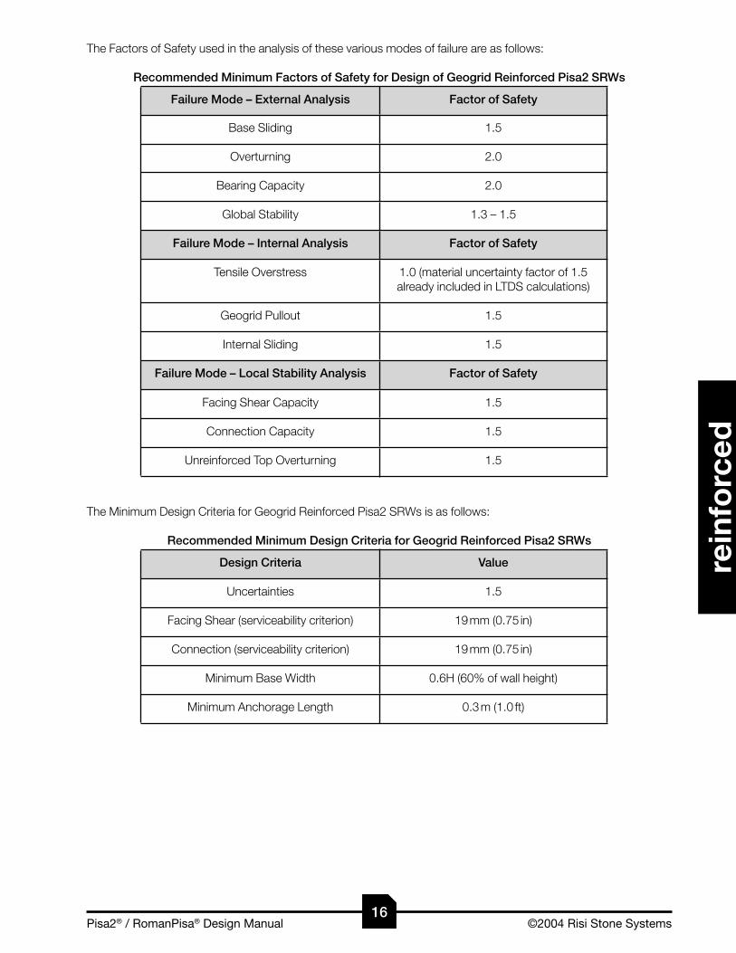
The Factors of Safety used in the analysis of these various modes of failure are as follows:
Recommended Minimum Factors of Safety for Design of Geogrid Reinforced Pisa2 SRWs
Failure Mode – External Analysis Factor of Safety
Base Sliding 1.5
Overturning 2.0
Bearing Capacity 2.0
Global Stability 1.3 – 1.5
Failure Mode – Internal Analysis Factor of Safety
Tensile Overstress 1.0 (material uncertainty factor of 1.5 already included in LTDS calculations)
Geogrid Pullout 1.5
Internal Sliding 1.5
Failure Mode – Local Stability Analysis Factor of Safety
Facing Shear Capacity 1.5
Connection Capacity 1.5
Unreinforced Top Overturning 1.5
The Minimum Design Criteria for Geogrid Reinforced Pisa2 SRWs is as follows:
Recommended Minimum Design Criteria for Geogrid Reinforced Pisa2 SRWs
Design Criteria Value
Uncertainties 1.5
Facing Shear (serviceability criterion) 19 mm (0.75 in)
Connection (serviceability criterion) 19 mm (0.75 in)
Minimum Base Width 0.6H (60% of wall height)
Minimum Anchorage Length 0.3 m (1.0 ft)
16

Pisa2® / RomanPisa® Design Manual ©2004 Risi Stone Systems
RisiStoneretaining wall systems
reinforced
Pisa2® / RomanPisa® Design Manual ©2004 Risi Stone Systems
RisiStoneretaining wall systems
rein
forc
ed
hinge height conceptThe flexible nature of the dry-stack Pisa2 SRW construction and the limited ability of units to transmit moments is accounted for by implementing a maximum height of influence criteria. This is referred to as the hinge height. The hinge height (Hh) is related to the maximum number of Pisa2 SRW units that can be stacked in an isolated column at the total wall inclination (Ψ) without toppling.
By utilizing the hinge height, the analysis will restrict the maximum design weight of the dry-stacked column of Pisa2 SRW units that can be transferred to the underlying wall units or base. By ignoring the hinge height restrictions, the magnitude of the normal pressure at shear interfaces would be overestimated and the completed analysis results could allow wall heights that will not satisfy minimum global stability requirements.
calculation of hinge heightThe hinge height can be found by calculating the moment about the heel of the wall for each successive course. The elevation where the total moment equal to zero will define the hinge height. This can be quickly calculated by:
Eq. 4-01
Eq. 4-02
The effective height of the wall is the true vertical height calculated by considering the effects of inclining the base of the wall.
The total inclination of the wall is determined by summing the effective batter of the wall due to the unit course set-back and the inclination of the base of the wall.
hinge height
ω
Hu
W
H
u
h
HW G
hu u=
−( )2tanω
H H H Hh h≤ = , else
H H i H H ie b u b= − −( ) cos tan sinω
ψ ω= + ib
17

Pisa2® / RomanPisa® Design Manual ©2004 Risi Stone Systems
RisiStoneretaining wall systems
reinforced
Pisa2® / RomanPisa® Design Manual ©2004 Risi Stone Systems
RisiStoneretaining wall systems
rein
forc
ed
external stability
There are three modes of failure which are examined for external stability of reinforced soil retaining walls.
Base SlidingLateral movement of the reinforced soil block at the base due to inadequate lateral shear capacity of the interface between the reinforced soil mass and supporting foundation soils.
OverturningRotation about the toe of the reinforced soil block.
Bearing CapacityShear failure of the foundation soils resulting in tilting, or collapse, of the reinforced soil block.
Coulomb theory is used to relate the lateral earth pressure to the vertical pressure for the active condition. A trian-gular pressure distribution is assumed for the lateral stresses in the soil due to the soil self-weight and a rectangular pressure distribution due to the contribution of any uniformly distributed surcharge. The orientation of the lateral ac-tive earth pressure is not horizontal, but is inclined at some angle (δe) measured from the inclined wall surface (Ψ).
calculation of external earth forcesThe inclination of the lateral earth force orientation with respect to the reinforced infill inclination is assumed to be:
Eq. 3-16
with the restriction that
Eq. 3-18
The external active earth pressure can be calculated as:
Eq. 3-11
with the external critical failure plane being oriented at:
Eq. 3-14
β
Hu
WH
Hemb L
u
Y
Ps
Pq
δe−Ψ δe−Ψ
e
s
Yq
q
αe
ω
Infill Soilγ , φ i i
Retained Soilγ , φ
Foundation Soilγ , φ ,
r r
f f fc
δ φ φe i r= the lessor of or
ω δ ω δ< <i e and
Ka =+( )
−( ) ++( ) −( )−( ) +(
cos
cos cossin sin
cos cos
2
2 1
φ ω
ω ω δφ δ φ βω δ ω β ))
2
tantan tan tan cot tan
α φφ β φ β φ β φ ω δ ω
−( ) =− −( ) + −( ) −( ) + +( ) + −( )1 ccot
tan tan cot
φ ω
δ ω φ β φ ω
+( ) + −( ) −( ) + +( ) 1
18

Pisa2® / RomanPisa® Design Manual ©2004 Risi Stone Systems
RisiStoneretaining wall systems
reinforced
Pisa2® / RomanPisa® Design Manual ©2004 Risi Stone Systems
rein
forc
ed
internal stability
Before beginning the internal stability calculations, an initial reinforcement layout needs to be created by determin-ing minimum geogrid requirements.
determining minimum geogrid requirementsFinal determination of the number of layers, lengths, types, and spacing of the geogrid reinforcement is an iterative process which requires analysis of the internal and local stability, and then making changes where required. To be-gin the process, it is necessary to create an initial design.
The minimum number of geogrid layers required can be calculated by dividing the total lateral load applied to the facia column by the allowable design load for the geosynthetic reinforcement.
Eq. 5-33
The next step is to position the required reinforcement layers at the maximum allowable spacing. Since the earth pressure increases with depth, the spacing be-tween layers of reinforcement will decrease near the bottom of the wall.
The total lateral load applied to the Pisa2 facia column is created by the earth pressure and surcharge.
Eq. 5-31
Both of the lateral forces generated by the earth pres-sure and surcharge are inclined and must resolve into horizontal and vertical components. Both of the vertical components are conservatively ignored.
Eq. 5-29
Eq. 5-30
The long term design strength (LTDS) of a geosynthetic reinforcement layer is calculated using the minimum aver-age roll value (MARV) for the wide-width tensile strength (ASTM D 4595) for the material. This value is then reduced to take biological and chemical durability (RFD), installation damage (RFID), and creep (RFCR) into consideration.
Eq. 3-20
The allowable tensile load that a single reinforcement layer can handle if defined as the long term design strength divided by the required factor of safety for tensile overstress.
Eq. 3-21
internal stability analysisThere are three potential modes of failure that should be considered in internal stability calculations for reinforced soil retaining walls.
β
ω
He
q
Y'
P's
P'q
δi −Ψ δi −Ψ
s
Y'q
αi
Ta(3)
Ta(2)
Ta(1)
NP'Ta H
amin
( )=
P' P' P'a H s H q H( ) ( ) ( )= +
P' K Hs H a i i( ) cos( )= −12
2γ δ ω
P' q q K Hq H l d a i( ) cos= +( ) −( )δ ω
LTDST
RF RF RFnult n
D n ID n CR n( )
( )
( ) ( ) ( )
=
TLTDSFSa n
n
to( )
( )
(min)
=
19

Pisa2® / RomanPisa® Design Manual ©2004 Risi Stone Systems
RisiStoneretaining wall systems
reinforced
Pisa2® / RomanPisa® Design Manual ©2004 Risi Stone Systems
rein
forc
ed
Soil / Geogrid PulloutThis mechanism refers to pullout of the reinforcement from within the reinforced soil mass due to inadequate an-chorage length between the soil and reinforcement layers.
Geogrid OverstressingExcessive strain, or rupture, of the geogrid due to lateral earth pressures that exceed the safe design strength of the geogrid reinforcement.
Internal SlidingGeosynthetic reinforcement layers may create preferred planes of sliding at various elevations throughout the height of the wall.
Coulomb theory is used to relate the lateral earth pressure to the vertical pressure for the active condition. A trian-gular pressure distribution is assumed for the lateral stresses in the soil due to the soil self-weight and a rectangular pressure distribution due to the contribution of any uniformly distributed surcharge. The orientation of the lateral ac-tive earth pressure is not horizontal, but is inclined at some angle (δi) measured from the inclined wall surface (Ψ).
Calculation of Internal Earth ForcesThe inclination of the lateral earth force orientation with respect to the SRW back inclination is assumed to be:
Eq. 3-17
with the restriction that,
Eq. 3-18
The internal active earth pressure can be calculated as:
Eq. 3-11
with the internal critical failure plane being oriented at:
Eq. 3-14
β
ω
HuW
H
u Y'
P's
P'q
δi −Ψ δi −Ψ
e
s
Y'q
q
αi
δ φi i= 23
ω δ ω δ< <i e and
Ka =+( )
−( ) ++( ) −( )−( ) +(
cos
cos cossin sin
cos cos
2
2 1
φ ω
ω ω δφ δ φ βω δ ω β ))
2
tantan tan tan cot tan
α φφ β φ β φ β φ ω δ ω
−( ) =− −( ) + −( ) −( ) + +( ) + −( )1 ccot
tan tan cot
φ ω
δ ω φ β φ ω
+( ) + −( ) −( ) + +( ) 1
soil / geogrid pullout While the length of the geogrid reinforcement layers is initially determined by the external stability analysis, the length of reinforcement that extends beyond the internal critical failure plane must provide adequate anchorage to prevent the pullout of the reinforcement from the soil.
The factor of safety for a soil / geogrid pullout is calculated for each layer of reinforcement as the ratio of the resist-ing soil anchorage capacity to the destabilizing lateral force generated by the earth pressure and surcharge for the contributing area of the wall.
Eq. 5-44
FS ACFpo
n
g n
=( )
20

Pisa2® / RomanPisa® Design Manual ©2004 Risi Stone Systems
reinforced
Pisa2® / RomanPisa® Design Manual ©2004 Risi Stone Systems
rein
forc
ed
Calculating Soil / Geogrid PulloutThe reinforcement layers are numbered from 1 to N starting with the bottom layer.
The anchorage capacity (AC(n)) for a given layer is the frictional resistance created between the soil and rein-forcement beyond the critical failure plane. The coef-ficient of interaction (Ci) between the geogrid and soil is obtained from pullout tests using similar soils and reinforcement. In the absence of data, it is suggested to use a value between 0.5 and 0.7.
Eq. 5-45
The anchorage length (La(n)) is the portion of the total geogrid length (L(n)) that extends past the internal critical failure plane into the stable soil mass.
Eq. 5-46
The normal force used to calculate the frictional anchorage capacity is calculated using the weight of the infill and the average depth of overburden (d(n)). The average depth of overburden extends from the reinforcement layer to the surface directly above the centre of the anchorage length.
Eq. 5-47
The effective elevation of the reinforcement is:
The tensile load (Fg(n)) developed in a reinforcement layer is calculated by integrating the horizontal component of the lateral soil pressure and surcharge over the effective height of the contributory area (Ac(n)). It is conservatively as-sumed that the tensile load is uniform over the entire length of the reinforcement.
Eq. 5-36
The contributory area (Ac(n)) for a reinforcement layer extends from the mid-point between layer n and the layer be-low it (n-1), up to the mid-point between layer n and the layer above it (n+1).
Eq. 5-39
For the bottom layer the contributory area extends to the base of the wall.
Eq. 5-37
For the top layer the contributory area extends to the top of the wall.
Eq. 5-40
To calculate the tensile load placed on a reinforcement layer, the depth of soil (D(n)) from the top of the wall, down to the mid-point of the contributory area must be determined to calculate the average lateral pressure. When there is non-uniform spacing of the reinforcement, the depth of the mid-point will vary from the effective elevation of the reinforcement (Ee(n)). For the bottom layer use:
β
ω
Hu
He
q
Ac(3)
Ac(2)
Ac(1)
D(2)
E (2)
Fg(2)
La(2)
αi
AC(2)
d(2)
La(2)/2
AC L C d qn a n i n i d i= +( )2 ( ) tanγ φ
L L W E Ea n u n i n( ) ( ) ( )tan tan= − − −( ) +90 α ω
d H EE
H Ln nn
ia n= −( ) +
− +
( )
( )( )tan
tan tanα
ω β23
E E i E H ie n n b n u b( ) ( ) ( )cos tan sin= − −( ) ω
F D q q K Ag n i n l d a c n i( ) ( ) cos= + +( ) −( )γ δ ω
A E Ec n n n( ) ( ) ( )= − + −1
2 1 1
A E Ec( ) ( ) ( )11
2 2 1= +
A H E Ec n n n( ) ( ) ( )= − + −1
2 1
21

Pisa2® / RomanPisa® Design Manual ©2004 Risi Stone Systems
reinforced
Pisa2® / RomanPisa® Design Manual ©2004 Risi Stone Systems
rein
forc
ed
Eq. 5-41For intermediate layers use:
Eq. 5-42
For the top layer use:
Eq. 5-43
D H h A A A An c c c n c n= + − − − − −−( ) ( ) ( ) ( ) ( )1 2 11
2K
D AN c N= 12 ( )
geogrid overstressGeogrid overstressing is considered to occur if the tensile forces acting in any layer of geogrid exceed the design strength of the reinforcement, causing excessive strain or rupture to occur.
The factor of safety for geogrid overstressing is calcu-lated for each layer of reinforcement as the ratio of the long term design strength to the destabilizing lateral force generated by the earth pressure and surcharge for the contributing area of the wall.
Calculating Geogrid OverstressingThe reinforcement layers are numbered from 1 to N starting with the bottom layer.
The long term design strength (LTDS) of a geosynthetic reinforcement layer is calculated using the minimum aver-age roll value (MARV) for the wide width tensile strength (ASTM D 4595) for the material. This value is then reduced to take biological and chemical durability (RFD), installation damage (RFID), and creep (RFCR) into consideration.
Eq. 3-20
The effective elevation for each reinforcement layer is:
The tensile load (Fg(n)) developed in a reinforcement layer is calculated by integrating the horizontal component of the lateral soil pressure and surcharge over the effective height of the contributory area (Ac(n)). It is conservatively as-sumed that the tensile load is uniform over the entire length of the reinforcement.
Eq. 5-36
The contributory area (Ac(n)) for a reinforcement layer extends from the mid-point between layer n and the layer be-low it (n-1), up to the mid-point between layer n and the layer above it (n+1).
Eq. 5-39For the bottom layer the contributory area extends to the base of the wall.
Eq. 5-37
β
ω
Hu
He
q
Ac(3)
Ac(2)
Ac(1)
D(1)
D(2)
D(3)
E (2)
E
E (1)
Fg(2)
αi
(3)
Fg(3)
Fg(1)
LTDST
RF RF RFnult n
D n ID n CR n( )
( )
( ) ( ) ( )
=
E E i E H ie n n b n u b( ) ( ) ( )cos tan sin= − −( ) ω
F D q q K Ag n i n l d a c n i( ) ( ) cos= + +( ) −( )γ δ ω
A E Ec n n n( ) ( ) ( )= − + −1
2 1 1
A E Ec( ) ( ) ( )11
2 2 1= +
D H h Ac 111
2= + −( ) ( )
FSLTDSFto n
n
g n( )
( )
( )
=
22

Pisa2® / RomanPisa® Design Manual ©2004 Risi Stone Systems
reinforced
Pisa2® / RomanPisa® Design Manual ©2004 Risi Stone Systems
rein
forc
ed
For the top layer the contributory area extends to the top of the wall.
Eq. 5-40
To calculate the tensile load placed on a reinforcement layer, the depth of soil (D(n)) from the top of the wall, down to the mid-point of the contributory area must be determined to calculate the average lateral pressure. When there is non-uniform spacing of the reinforcement, the depth of the mid-point will vary from the effective elevation of the reinforcement (Ee(n)). For the bottom layer use:
Eq. 5-41For intermediate layers use:
Eq. 5-42
For the top layer use:
Eq. 5-43
D H h Ac 111
2= + −( ) ( )
D H h A A A An c c c n c n= + − − − − −−( ) ( ) ( ) ( ) ( )1 2 11
2K
D AN c N= 12 ( )
internal slidingThe analysis for internal sliding is similar to external base sliding stability calculations, however, the sliding resistance is developed by shear at the unit-to-unit interface and friction along a reduced length of the reinforcement layer.
The factor of safety for a base sliding failure is calculated as the ratio of the resisting shear force and friction at the sliding surface to the destabilizing lateral force generated by the earth pressure and applied surcharge.
Eq. 5-48
Calculating Internal SlidingThe reinforcement layers are numbered from 1 to N starting with the bottom layer.
The sliding resistance over the reinforcement layer is calculated using the infill soil properties and the weight of the soils above. The coefficient of direct sliding ( Cds ) between the geogrid and soil is ob-tained from pullout tests using similar soils and reinforcement. In the absence of data, it is sug-gested to use a value between 0.7 and 0.95.
Eq. 5-49
Eq. 5-55
Eq. 5-56
The effective height of the reinforcement layers is:
The sliding surface is equal to the length of the reinforcement layer reduced by the width of the SRW unit and the position of the critical failure plane within the reinforced soil mass.
FSR' VPsl ns n u
a H n( )
( )
( , )
=+
A H E Ec n n n( ) ( ) ( )= − + −1
2 1
R' C q L W' W's n ds d n r i n r n i( ) ( ) ( , ) ( , ) tan= + +( )β β φ
W' L' H Er i n s n n I( , ) ( ) ( )= −( )γW' L L'r n i n s n( , ) ( ) ( ) tanβ βγ β= 1
2
E E i E H ie n n b n u b( ) ( ) ( )cos tan sin= − −( ) ω
Lβ
β
h
Wr(i,2)
ω
ω
HuW
H
Lu
PPq(2)
δe−Ψ δe−Ψ
W'
R'e
βr( ,2)
q
s(2)
(2)
(2)
L'∆L(2)
s(2)
Ww(2)
Vu(2)
s(2)
E (2)
αe
23

Pisa2® / RomanPisa® Design Manual ©2004 Risi Stone Systems
reinforced
Pisa2® / RomanPisa® Design Manual ©2004 Risi Stone Systems
rein
forc
ed
Eq. 5-50
The critical failure plane has the potential to propagate from a point on the reinforcement layer, up and back into the retained soil so it just intercepts the end of the reinforcement layer above. This will effectively reduce the sliding length by:
Eq. 5-48
The shear capacity (Vu(n)) is calculated based on laboratory-testing–determined parameters (au, λu) that are specific to the SRW system and the normal load (Ww(n)) above the reinforcement layer created by the column of SRW units.
Eq. 4-25
The horizontal shear capacity can be slightly increase by the required lifting action of the column of the SRW units above, if the base is inclined.
The normal load for the resisting shear force is calculated as the weight of the column of the SRW units above the interface being considered while implementing the hinge height.
Eq. 4-09Only the portion of the lateral earth force and surcharge above the nth reinforcement layer under consideration is calculated. This force is applied to a plane parallel to the facia near the back of the reinforced soil.
Eq. 5-11Both of the lateral forces generated by the earth pressure and surcharge are inclined and must resolve into horizon-tal and vertical components. Both of the vertical components are conservatively ignored.
Eq. 5-06
Eq. 5-08
L' L W Ls n u( ) ( )= − − ∆
∆LE En n
e
=−+( ) ( )
tan1
α
V a Wu u W u= + tanλ
V V W ih n u n w n b( ) ( ) ( ) sin= +
W H Ww h u u= γ
P P Pa H s H q H( ) ( ) ( )= +
P K H hs H a i e( ) cos= +( ) −( )12
2γ δ ω
P q q K H hq H d a e e( ) cos= +( ) +( ) −( )1 δ ω
V Vu n u( ) (max)≤
24

Pisa2® / RomanPisa® Design Manual ©2004 Risi Stone Systems
RisiStoneretaining wall systems
reinforced
Pisa2® / RomanPisa® Design Manual ©2004 Risi Stone Systems
rein
forc
ed
local stability
There are three potential modes of failure that should be considered for local stability calculations of reinforced soil retaining walls.Facia/Geogrid Connection CapacityPullout or rupture of the reinforcement at the frictional connection formed by the clamping action of the modular blocks on either side of the reinforcement at the facia.
Facia Shear/BulgingExcessive deformation or shear failure between successive courses of facing units.
Unreinforced HeightThe top of the retaining wall structure must be less than the maximum unreinforced height to ensure the top of the wall acts as a stable conventional retaining wall.
facia/geogrid connection capacityTo resist lateral earth pressures, the SRW units must have sufficient geogrid connection capacity to transfer the applied forces to the reinforcement layers. The connection capacity is developed by shear resistance between the reinforcement and the top and bottom of the SRW units, including the shear key.
The factor of safety for facia / geogrid connection capacity is calculated as the ratio of the maximum facia / geogrid connection capacity to the destabilizing lateral force generated by the earth pressure and surcharge for the contrib-uting area of the wall.
Calculating Facia/Geogrid Connection CapacityThe reinforcement layers are numbered from 1 to N starting with the bottom layer.
The connection capacity (Sc(n)) is calculated based on laboratory-testing–determined parameters (acs, λcs) that are specific to the SRW system and the normal load (Ww(n)) on the connection created by the column of SRW units above.
Eq. 5-59
The normal load for the resisting shear force is calculated as the weight of the column of the SRW units above.
Eq. 4-09The effective elevation for each reinforcement layer is:
The tensile load (Fg(n)) developed in a reinforcement layer is calculated by integrating the horizontal component of the lateral soil pressure and surcharge over the effective height of the contributory area (Ac(n)). It is conservatively as-sumed that the tensile load is uniform over the entire length of the reinforcement.
Eq. 5-36
FSS iFcs n
c n b
g n( )
( )
( )
cos=
β
ω
Hu
He
q
Ac(3)
Ac(2)
Ac(1)
D(1)
D(2)
D(3)
E (2)
E
E (1)
Fg(2) (3)
Fg(3)
Fg(1)
Ww(3)
Ww(2)
Ww(1)
Sc(2)
Sc(3)
Sc(1)T a Wultconn n cs w n cs( ) ( ) tan= + λ
S Sc n c( ) (max)≤
W H Ww h u u= γ
E E i E H ie n n b n u b( ) ( ) ( )cos tan sin= − −( ) ω
F D q q K Ag n i n l d a c n i( ) ( ) cos= + +( ) −( )γ δ ω
25

Pisa2® / RomanPisa® Design Manual ©2004 Risi Stone Systems
RisiStoneretaining wall systems
reinforced
Pisa2® / RomanPisa® Design Manual ©2004 Risi Stone Systems
rein
forc
ed
The contributory area (Ac(n)) for a reinforcement layer extends from the mid-point between layer n and the layer be-low it (n-1), up to the mid-point between layer n and the layer above it (n+1).
Eq. 5-39For the bottom layer the contributory area extends to the base of the wall.
Eq. 5-37For the top layer the contributory area extends to the top of the wall.
Eq. 5-40
To calculate the tensile load placed on a reinforcement layer, the depth of soil (D(n)) from the top of the wall, down to the mid-point of the contributory area must be determined to calculate the average lateral pressure. When there is non-uniform spacing of the reinforcement, the depth of the mid-point will vary from the effective elevation of the reinforcement (Ee(n)). For the bottom layer use:
Eq. 5-41
For intermediate layers use:
Eq. 5-42
For the top layer use:
Eq. 5-43
A E Ec n n n( ) ( ) ( )= − + −1
2 1 1
A E Ec( ) ( ) ( )11
2 2 1= +
A H E Ec n n n( ) ( ) ( )= − + −1
2 1
D H h A A A An c c c n c n= + − − − − −−( ) ( ) ( ) ( ) ( )1 2 11
2K
D AN c N= 12 ( )
D H h Ac 111
2= + −( ) ( )
facia/shear capacityTo resist lateral earth pressures, the SRW units must have sufficient interface shear capacity to transfer the applied forces to the SRW units below and eventually to the reinforcement and base of the structure.
The factor of safety for facia shear/bulging is calculated as the ratio of the resisting shear force at the unit to unit interface to the destabilizing lateral force generated by the earth and surcharge pressure, less the tensile loads ap-plied to the reinforcements above.
Eq. 5-61
Calculating Facia ShearThe SRW courses are numbered from 1 to M start-ing with the bottom course.
The shear capacity (Vu(m)) is calculated based on lab-oratory-testing–determined parameters (au, λu) that are specific to the SRW system and the normal load (Ww(m)) above the interface created by the column of SRW units.
Eq. 4-25
FSV
P' F Fsc nu n
a H n g n g n( )
( )
( , ) ( ) ( )
=− + +( )+ +1 2 K
β
ωω
HuW
H
Lu
P'P'q(6)
δ i −Ψ δ i −Ψ
e
q
Ww(6)
Vu(6)
s(6)
E (2)
Fg(3)
Ac(3)
Ac(2)
Ac(1)
D(2)
V a Wu u W u= + tanλ
V Vu m u( ) (max)≤
26

Pisa2® / RomanPisa® Design Manual ©2004 Risi Stone Systems
reinforced
Pisa2® / RomanPisa® Design Manual ©2004 Risi Stone Systems
rein
forc
ed
The horizontal shear capacity can be slightly increased by the required lifting action of the column of the SRW units above, if the base is inclined.
The normal load for the resisting shear force is calculated as the weight of the column of the SRW units above.
Eq. 4-09The height of the SRW units above the interface being considered is calculated while implementing the hinge height restrictions.
Only the portion of the lateral earth force and surcharge above the mth course interface under consideration is cal-culated. This force is applied to the back of the SRW units.
Eq. 5-31Both of the lateral forces generated by the earth and surcharge pressure are inclined and must resolve into horizon-tal and vertical components. Both of the vertical components are conservatively ignored.
Eq. 5-29
Eq. 5-30The reinforcement layers are numbered from 1 to N starting with the bottom layer.
The tensile load (Fg(n)) developed in a reinforcement layer is calculated by integrating the horizontal component of the lateral soil pressure and surcharge over the effective height of the contributory area (Ac(n)). It is conservatively as-sumed that the tensile load is uniform over the entire length of the reinforcement.
Eq. 5-36The contributory area (Ac(n)) for a reinforcement layer extends from the mid-point between layer n and the layer be-low it (n-1), up to the mid-point between layer n and the layer above it (n+1).
Eq. 5-39For the bottom layer the contributory area extends to the base of the wall.
Eq. 5-37For the top layer the contributory area extends to the top of the wall.
Eq. 5-40
The effective elevation for each reinforcement layer is:
To calculate the tensile load placed on a reinforcement layer, the depth of soil (D(n) ) from the top of the wall, down to the mid-point of the contributory area must be determined to calculate the average lateral pressure. When there is non-uniform spacing of the reinforcement, the depth of the mid-point will vary from the effective elevation of the reinforcement (Ee(n)). For the bottom layer use:
V V W ih m u m w m b( ) ( ) ( ) sin= +
W H Ww h u u= γ
H H mHu m Mm( ) = − = , 1K
H H H Hm h m h( ) ( )≤ = , else
H H i H Hu ie m m b m b( ) cos tan sin= − −[ ] ω
P' P' P'a H s H q H( ) ( ) ( )= +
P' K Hs H a i i( ) cos( )= −12
2γ δ ω
P' q q K Hq H l d a i( ) cos= +( ) −( )δ ω
F D q q K Ag n i n l d a c n i( ) ( ) cos= + +( ) −( )γ δ ω
A E Ec n n n( ) ( ) ( )= − + −1
2 1 1
A E Ec( ) ( ) ( )11
2 2 1= +
A H E Ec n n n( ) ( ) ( )= − + −1
2 1
E E i E H ie n n b n u b( ) ( ) ( )cos tan sin= − −( ) ω
27

Pisa2® / RomanPisa® Design Manual ©2004 Risi Stone Systems
reinforced
Pisa2® / RomanPisa® Design Manual ©2004 Risi Stone Systems
rein
forc
ed
Eq. 5-41For intermediate layers use:
Eq. 5-42For the top layer use:
Eq. 5-43
D H h A A A An c c c n c n= + − − − − −−( ) ( ) ( ) ( ) ( )1 2 11
2K
D H h Ac 111
2= + −( ) ( )
D AN c N= 12 ( )
unreinforced top overturningThe top few SRW units above the top layer of reinforcement create a conventional retaining wall structure. They must have sufficient mass to prevent their forward rotation about the toe of the bottom unit.
The factor of safety for an unreinforced height over turning failure is calculated as the ratio of the resisting moment of the wall above the top layer of reinforcement to the destabilizing moment generated by the earth pressure and applied surcharge, resolved about the toe of the SRW unit above the top layer of reinforcement.
Eq. 4-14
Calculating Unreinforced Height OverturningThe resisting moment is created by the weight of the facia.
Eq. 4-15The force for the resisting moment is calcu-lated as the weight of the wall.
Eq. 4-09The moment arm for the resisting moment is created by the effective batter of the wall and inclination of the base.
Eq. 4-16
The height of the unreinforced portion of the wall will be:
The maximum stabilizing force created by the unreinforced portion of the wall has to be restricted by the hinge height.
The destabilizing moment is created by the earth pressure and surcharge.
Eq. 4-17Both of the lateral forces generated by the earth pressure and surcharge are inclined and must resolve into horizon-tal and vertical components. Both of the vertical components are conservatively ignored.
Eq. 5-29
Eq. 5-30
The effective height of the wall is the true vertical height calculated by considering the effects of inclining the base
FS MMot
r
o
=
M W Xr w w=
W H Ww h u u= γ
X G H Hw u h u= + −( ) 12 tanω
β
Ww(m)
ωω
W
H
u
Y
P's(m)P'q(m)
δe−Ψ
(m)Xw(m)
s(m)
q
δe−Ψ
Ys(m)
Hu
H H mHu mm( ) = − = , course number below top geogrid (N)
H H H Hm h m h( ) ( )≤ = , else
M PY PYo s s q q= +
P' K Hs H a i i( ) cos( )= −12
2γ δ ω
P' q q K Hq H l d a i( ) cos= +( ) −( )δ ω
28

Pisa2® / RomanPisa® Design Manual ©2004 Risi Stone Systems
reinforced
Pisa2® / RomanPisa® Design Manual ©2004 Risi Stone Systems
RisiStoneretaining wall systems
spec
ial c
ond
itio
ns
of the wall.
The force due to the earth pressure is assumed to act at a point one third the effective wall height above the top reinforcement layer.
Eq. 4-07The force due to the surcharge is assumed to act at a point one half the effective wall height above the top rein-forcement layer.
Eq. 4-08
H H i H Hu ie m m b m b( ) cos tan sin= − −[ ] ω
Y Hs = 13
Y Hq = 12
29

Pisa2® / RomanPisa® Design Manual ©2004 Risi Stone Systems
reinforced
Pisa2® / RomanPisa® Design Manual ©2004 Risi Stone Systems
RisiStoneretaining wall systems
spec
ial c
ond
itio
ns
special conditions
Special consideration must be given to conditions that may generate additional loads on the Pisa2 segmental re-taining wall not accounted for in the standard analysis. The following section identifies some of these conditions and discusses how they can be approached. We have broadly categorized these conditions under the following headings:
• Other Structures
• Terracing
• Water Applications
30

Pisa2® / RomanPisa® Design Manual ©2004 Risi Stone Systems
RisiStoneretaining wall systems
special co
nditio
ns
Pisa2® / RomanPisa® Design Manual ©2004 Risi Stone Systems32
spec
ial c
ond
itio
ns
other structures
pedestrian handrails (non–wind-bearing)Most building codes require a pedestrian handrail to be placed behind walls that exceed 0.6 m (2.0 ft) in height. From a design perspective, the additional loads placed on the handrail must be accounted for. Local building codes usually specify the minimum height of the railing and corresponding lateral pedestrian load. Based on typical values common to most codes, and through our own experience, we have determined that it is not possible to mount a pedestrian handrail on top of a Pisa2 wall and still obtain the required design factors of safety. Instead, we recom-mend placing the handrail behind the wall, founded in equally spaced concrete foundations (sonotubes).
For conventional Pisa2 walls, the additional force generated by the concrete handrail foundation against the back of the wall normally exceeds the available resistance produced from the self weight of the blocks alone. As a result, we recommend extending the concrete sonotubes well below the base of the wall into a “socket” of undisturbed material. Essentially, the design must assume the conventional Pisa2 wall provides no additional resistance and the underlying soil is capable of carrying the moment-induced lateral load. Past projects have seen the sonotube extending a minimum of 1.2 m (4.0 ft) below the base of the wall (i.e. for a wall that is 0.6 m [2.0 ft] above grade, the total handrail foundation depth would be 1.8 m).
For geogrid-reinforced Pisa2 walls, since the allowable heights are significantly increased, the method discussed above – extending the handrail foundations below the base of the wall – is not realistic. As a result, the geogrid rein-forcement must be designed to resist the lateral loads imparted by the handrail. In a typical situation, a 1.2 m (4.0 ft) foundation depth is sufficient to distribute the applied loads into the reinforced zone of the wall. The recommended analysis involves first determining the zone of influence created by the handrail foundations and then identifying the layers of geogrid being impacted. As the handrail exists within the reinforced zone, only internal and local stability modes of failure (facia connection, tensile overstress, and anchorage capacity) are required to be checked for the additional loads.
acoustic/privacy fences (wind-bearing)Design considerations for acoustic and privacy fences are basically the same as for the pedestrian handrails dis-cussed above. The key difference in these two structures is the fact that acoustic/privacy fences are assumed to take wind loads. The effect of wind loads is significant and can dramatically influence the wall design.
For Pisa2 conventional walls, ensuring the wind loads are transferred to well below the wall (refer to above discus-sion on Pedestrian Handrails) is critical to ensuring the long-term performance of the structure. While a 1.2 m (4.0 ft) depth is normally sufficient for a “below base” depth of foundation on a handrail application, the effect of the wind loads usually demands a significantly deeper placement. It is recommended that the acoustic fence designer be consulted to determine the required depth below the base of the wall.
For Pisa2 geogrid reinforced walls, as in the pedestrian handrail analysis, the geogrid reinforcement must be de-signed to incorporate the additional wind loads. As a general rule of thumb, the greater the depth of foundation, the more geogrid layers will be engaged, and the less the force will be imparted to each layer. In the past, we have been able to successfully design geogrid reinforced Pisa2 walls to accommodate the effects of solid fences behind them with a minimum foundation depth that exceeds the height of the fence.
other commentsIt is recommended that the foundations be placed as the wall is being constructed. This allows the contractor to properly wrap the geogrid reinforcement layers around the centerline of the foundations as the wall is being constructed (Refer to the Pisa2 Installation Guide for details). In contrast to the conventional method discussed above, the foundation will be placed in an engineered fill environment (versus the “socket” of native material). As a result, the compaction of the infill material (reinforced zone) around the foundation, and the proper placement of the geogrid reinforcement is critical to ensuring the required confining pressure.
For both handrails and fences, it is also recommended that the foundation be offset a minimum of 200 mm (8 in)
31
Pisa2® / RomanPisa® Design Manual ©2004 Risi Stone Systems
RisiStoneretaining wall systems
special co
nditio
ns
Pisa2® / RomanPisa® Design Manual ©2004 Risi Stone Systems32
spec
ial c
ond
itio
ns
from the back of the coping unit. This allows a buffer zone between the blocks and the rigid concrete sonotube to absorb any localized movement. If this is not possible, at the minimum, a 25 mm (1 in) layer of expansion joint mate-rial should be placed between these two elements.
building foundationsAlthough geogrid reinforced Pisa2 walls can be designed to withstand significant additional loading, the cost impli-cations are equally significant. In most cases, where building foundations and other structures are in close proximity to the proposed wall, it is recommended that the designer first make every effort to locate these elements outside of the zone of influence. Depending on the soil conditions on site, geotechnical engineers typically use between a 1H:1V and a 10H:7V line of influence. This imaginary line extends from the outside of the foundation footprint down towards the Pisa2 wall. Generally, if the line of influence intersects the back of the reinforced zone, some additional loading must be considered from the structure in the External Stability analysis. If the line of influence intersects the facing of the wall, this additional loading must be considered in the Internal Stability Analysis as well. Standard equations for line loads and strip loads are available in most geotechnical engineering texts.
Another issue that arises when dealing with placing buildings in close proximity to a Pisa2 geogrid reinforced seg-mental retaining wall is total and differential settlement. As segmental retaining walls are flexible structures, and buildings are general considered rigid structures, care must be taken to ensure the allowable settlement tolerances are compatible.
Finally, the placement of other structures within proximity to a Pisa2 SRW highlights the need to review the global stability of the new wall/building configuration.
abutting buildings and other structuresWhen abutting a Pisa2 SRW against existing structures, consideration must be given to the potential for the end of the wall (at the interface where it abuts the other structure) to be “hung-up” on the footing/foundation of the abutting structure. If the existing building footing has been in place for a longer period of time than the Pisa2 wall, any initial settlements will have likely already occurred. At the same time, the Pisa2 wall will typically undergo small post-construction settlements. If the end of the Pisa2 wall is bearing on or close to the existing building footing, the potential then exists for differential settlement. This type of settlement is often characterized by diagonal cracks propagating from the lowest point of the wall (at the Pisa2 wall/building interface) roughly at a 45 degree angle up through the wall. Although the Pisa2 system is structurally able to absorb these settlements to some degree, the cracking will likely become an aesthetic concern. Generally, if the building footing is well below grade and the mate-rial around the footing has been well compacted, this should not be a concern. If the structure footing is within a depth less than twice the footing width (for Pisa2 a standard footing width is 0.6m), additional measures should be considered to minimize the potential for differential settlement. Possible options include a reinforced concrete base, a geosynthetic reinforced granular base, or increasing the overall depth of the granular footing.
highway guide rails and crash barriersThere are two basic types of traffic restraint systems used on most highways: Guide Rails and Crash Barriers. Both of these systems may be integrated with the Pisa2 Geogrid reinforced SRW.
Guide RailsGuide Rails are considered flexible restraint systems that are designed to re-direct the path of an errant vehicle. Normally composed of wood or steel posts connected by a continuous steel beam, guide rails are meant to absorb impact through deformation. As a result, the integration of this type of structure with a geogrid reinforced Pisa2 SRW requires that a substantial buffer zone be maintained between the back of wall (back of coping unit) and the post line. This buffer zone both protects the Pisa2 wall and allows the guide rail to deform as was intended.
Current design methodology is somewhat limited in this respect. The FHWA’s Mechanically Stabalized Earth Walls and Reinforced Soil Slopes Design and Construction Guidelines (hereafter referred to as FHWA) recommends off-setting the flexible guide rail a distance of 1.0 m (3.0 ft) from the face of the wall and applying an additional 4.4 kN/m (300 lb/ lin.ft) to the top two layers of geogrid reinforcement. Risi Stone Systems recommends offsetting the post line 1.0 m (3.0 ft) from the back of the wall. It is our assertion that the FHWA recommendation does not properly account for the fact that SRW units may have varying depths and depending on the front-to-back dimension of the

Pisa2® / RomanPisa® Design Manual ©2004 Risi Stone Systems
special co
nditio
ns
Pisa2® / RomanPisa® Design Manual ©2004 Risi Stone Systems
RisiStoneretaining wall systems
spec
ial c
ond
itio
ns
coping unit, the potential exists to place the post line almost immediately behind the wall (i.e.If the coping depth were 500 mm [20 in], as seen in Risi Stone Systems’ SienaStone SRW, the offset to the post line is limited to just 500 mm [20 in]. Through our experience, we do not feel this distance provides an adequate buffer zone both protect the wall and allow the guide rail to serve [deform] as it was intended). Based on this logic, again, we suggest the post line be offset 1.0 m (3.0 ft) from the back of the coping unit.
Crash BarriersIn contrast to guide rails, crash barriers are rigid structures intended to re-direct the path of an errant vehicle by providing an immovable barrier (no deformation). These structures are typically composed of reinforced concrete with the basic configuration consisting of a vertical parapet integrated with a large cantilevered base. This type of structure is designed to independently absorb the required crash loads (various highway codes specify a range of potential crash loads) by transferring the load into the cantilevered base. From a Pisa2 geogrid reinforced design perspective, the load is then transferred through friction along the base of the cantilever into the reinforced zone of the wall. The load is assumed to be distributed to the upper portion of the wall and carried back into the anchorage zone of the infill through the geogrid reinforcements. Refer to your local highway design code for appropriate load-ing conditions and specifications.
33

Pisa2® / RomanPisa® Design Manual ©2004 Risi Stone Systems
special co
nditio
ns
Pisa2® / RomanPisa® Design Manual ©2004 Risi Stone Systems
RisiStoneretaining wall systems
spec
ial c
ond
itio
ns
Terracing walls can provide a number of benefits when the relevant design and construction issues are properly ad-dressed. When the space is available to do so, terracing allows the designer to reduce the applied foundation loads while minimizing the height of any single wall (for aesthetic purposes) and providing additional space for planting, walkways, etc.
Similar to the way building footings may impose additional loads as discussed above, the presence of a terraced wall(s) within close proximity of a Pisa2 SRW also applies an additional surcharge. In terracing applications, these additional loads must be considered for internal, external, and global stability of the structures.
To assess the effects of an upper wall on an adjacent lower wall, the NCMA Manual provides equations to calcu-late the dead loads based on the types of soil separating the walls, the offset distance, the wall heights, and cor-responding overall widths, and any additional loading. These loads are approximate and are to be applied to the internal and external stability calculations.
Terracing highlights the need for a global stability analysis to assess the resistance of the proposed configuration to a deep-seated or global failure. This type of failure is usually defined by a circular slip plane that propagates through the underlying soils. As the identification of the critical slip surface is a iterative process, a number of software pack-ages are available that perform this analysis.
terracing – conventional pisa2 wallsFor conventional Pisa2 SRWs, it is recommended that the walls be offset so as to not impose additional loads. In most cases, offsetting the Upper Wall from the back of the coping unit of the Lower Wall by a distance exceeding the Lower Wall height allows the designer ignore any potential influence effects.
terracing – geogrid-reinforced pisa2 wallsWith respect to terracing offset distances, three basic conditions exist:
1. The Upper Wall is located within the reinforced zone of the lower wall.
2. The Upper Wall is located outside of the reinforced zone, but within a distance less than twice the lower wall height.
3. The Upper Wall is located outside of the external zone of influence (approximately twice the lower wall height).
As noted in the discussion on building footings, any of these conditions can be designed for but generally, the closer the walls are together, the more costly they will be. Generally, Upper Walls placed within the reinforced zone of the Lower Wall will apply loads both internally and externally. This may require additional layers of geogrid reinforcement (tighter spacing) and/or greater reinforcement lengths (increasing the overall width of the wall). Placement outside of this area (Zone 2) will normally only apply loads related to external stability, thereby necessitating increased geogrid lengths. Generally, it is recommended that whenever possible, terraced walls be offset by a minimum distance equal to the wall height of the Lower Wall. This practice should generally reduce the applied internal loads and re-duce costs.
terraced walls
34

Pisa2® / RomanPisa® Design Manual ©2004 Risi Stone Systems
RisiStoneretaining wall systems
special co
nditio
ns
When designing and constructing Pisa2 SRWs in applications where the groundwater level exceeds the base of wall elevations, additional issues must be taken into account.
high groundwater levelsThe NCMA Manual provides drainage strategies to prevent the infiltration of groundwater into the SRW structures. Depending on the anticipated high groundwater level, the use of blanket and chimney drains wrapped in the appro-priate filter fabric can be an effective way of channelling water flow away from the reinforced zone of the Pisa2 SRW (Refer to Section 3.3 of the NCMA Manual).
submerged conditionsIn some cases, Pisa2 geogrid-reinforced walls can be constructed as pond or channel sidewalls, along lakeshores as erosion protection, or in landscaping water features. In these applications, where the potential exists for the Pisa2 wall to be partially or completely submerged, the designer must address a few key issues before deciding whether the particular application is a good fit for the Pisa2 System.
If it is anticipated that the wall will be subject to significant ice effects either through static adhesion to the face (po-tentially causing uplift of the wall), dynamic impact loads to the face (ice flows), or severe wave action, unless these loads can be diverted away from the wall through the use of properly sized erosion protection, it is our opinion that a segmental retaining wall (including the Pisa2 System) is not recommended. Large rip-rap placed in front of the wall may protect the wall from these effects by breaking up the ice before it is able to damage the wall, and/or by absorbing wave energy.
For the design of submerged Pisa2 geogrid reinforced retaining walls, the buoyant unit weights of the materials (soils and Pisa2 facing units) must be used in the analysis. As discussed, Risi Stone Systems normally recommends the use of free-draining (less than 8% fines), well-graded granular materials as infill for the reinforced zone (see Soils). For applications where the wall may be submerged, it is recommended that the same backfill material be used, with the addition of a 300 mm (12 in) clear stone (19 mm angular clean stone wrapped with an approved filter fabric) drainage layer immediately behind the facing. This additional drainage measure places larger, gap-graded angular stone immediately behind the facing, preventing the possibility of fines washing out and/or the build-up of a temporary hydrostatic pressure at this critical location.
rapid draw-down conditionIf the water level in front of the wall is anticipated to fall at a rate that exceeds the permeability of the infill material, a condition known as “rapid draw-down” must be addressed in the analysis. In this temporary condition, sometimes referred to as a “perched” water condition, a hydrostatic differential exists between the infill material and the water level in front of the wall. Due to the hydrostatic pressure, this scenario produces extremely high forces at the face of the wall. The FHWA recommends using a 1.0 m (3.0 ft) hydrostatic differential if it is anticipated that a rapid draw-down condition will occur.
wall embedment for water applicationsThe protection of the Pisa2 footing and foundation soils is critical, particularly in water applications where the po-tential for scouring exists. The FHWA recommends a minimum 0.6 m (2.0 ft) embedment depth of SRWs in water applications. Risi Stone Systems further recommends that if a granular base is used, it should be completely wrapped in an approved filter fabric to prevent washout. Use of a concrete foundation is also an acceptable option for water applications (reinforced or unreinforced – depending on settlement requirements) as it negates the need for compacting the base in conditions where moisture content is above optimal. It should be noted that installing a concrete base does not reduce the need for proper scour protection/embedment. If scour protection is not pro-vided, the potential for washout from underneath the concrete footing is equally problematic.
In addition to wall embedment, properly sized rip-rap or other erosion protection (articulated concrete revetment systems) must be placed in front of the Pisa2 Wall to maintain the required cover over the life of the structure.
water applications
35

Since 1974, innovation has been a way of
life for Risi Stone Systems. Today, Risi Stone
Systems’ retaining walls are the products
of choice for landscape, construction and
municipal projects internationally.
The patented components, developed by
Risi Stone Systems, have been licensed
to concrete producers in major markets
throughout the world. These producers
employ the latest computer and robotic
technology in the production of the finest
modular concrete retaining wall system.
If you would like further detailed information
about Risi Stone Systems and a wide range
of retaining wall systems, visit the Risi Stone
Systems website, http://www.risistone.com.
Or call us at 1.800.626.9255
The proprietary products and designs described herein are covered under one or more of the following: US Pat. 4,815,897 • US Pat. 4,490,075 • US Pat. 5,622,456 • US Pat. 5,064,313 • US Pat. D 403,437 • US Pat. D 403,785 • US Pat. D 370,272 • Cdn. Pat. 1,182,295 • Cdn. Pat. 1,204,296 • Cdn. Pat. 2,145,344
• Cdn. Pat. 2,017,578 • Ind. Des. 83,773 • Ind. Des. 78,184. Other domestic and foreign patents and designs are pending.
RisiStoneretaining wall systems
®