romac newsletter 2003 romac - university of virginia · 2003 romac newsletter bearings & seals...
TRANSCRIPT

RO
MA
C
2 0 0 3 R O M A C N E W S L E T T E R
B E A R I N G S & S E A L S
4
R O T O R D Y N A M I C -I C S
8
F L U I D F L O W S 1 1
M A G N E T I C B E A R I N G S
1 3
S O F T W A R E H I G H L I G H T S
1 7
H E A R T P U M P 1 8
INSIDE THIS ISSUE:
Update on the
Rotating
Machinery
Stability Test Rig
Rotating Machinery and Controls Laboratory
Maximum Temperature vs Shaft Speed, Conventional and Directly Lubricated Bearings(See Maxbrg)
Above: Startup Bode Plot of Stability Test Rig
Below Right: Stability Test Rig: Updates on Page 9)
Temperature Distribtuion across Film and Pad (Film Thickness x 1000) See Maxbrg article on page 4
43
45
45
45
46
4 6
46
47
47
48
48
48
49
49
50
50
50
51
51
52
52
52
53
53
54
5455
56
56
57 58
Circumferential Direction
Rad
ialD
irec
tion
0 50 100 150 200 250 300-50
0
50
100
150
200
250
300
Ferron etal BearingTemperature ContourN=4000 rpm, W=6 kN
Pad
F ilm
Shaft Speed (rpm)
Tem
per
atu
re(C
)
0 3000 6000 9000 12000 15000 1800050
60
70
80
90
100
110
120
130
Experiment, Conv.(op), 11121 NExperiment, LEG.(op), 11121 NTEHD, Conv.(op), 11121 NTEHD, LEG (op), 11121 N

Paul Allaire, Wade Professor of Mechanical and Aerospace Engi-neering and Director of ROMAC
and Eric Maslen. The new/old ROMAC Director is Paul Allaire for the next three years. This is the first time he has been the Direc-tor since his first term in 1980 to 1983.
ANNUAL FEES AND FI-NANCIAL POSITION
Our membership fee of $16,000 per year is un-changed for next year. The total income to ROMAC is estimated at $344,000 with net income after UVA over-head (20%) of $292,000. The expenses are faculty summer salary $90,000, stu-dent support $165,000, travel $11,000, part time staff $18,000, office ex-penses $33,000, and annual meeting expenses $21,000. We are about on budget for this year. Many of this year’s expenses will be similar to last year’s ex-penses and there are other companies interested in joining ROMAC.
A former ROMAC com-pany member, Turbocare, has informed us that they are rejoining for next year. We are also discussing re-newed membership with Kingsbury, Inc.
ROMAC NEWSLET-TER/ANNUAL MEET-ING SUMMARY
Dear Romac Member:
The 23rd Annual RO-MAC Meeting was held June 2-4, 2003. To me and other ROMAC faculty members, it is pretty amazing that we have made it through 23 years. A number of companies were not able to make it to the meeting so we are sending out this newsletter to let you better know what is going on , as well as to those who were there.
ANNUAL CURRENT MEMBERSHIP AND MEETING ATTENDANCE
First, let us thank you for being long term industrial members of the Rotating Ma-chinery and Controls Indus-trial Program. We have 27 industrial members which has been reasonably stable in re-cent years following quite a few company mergers and generally tough economic times. There were 26 indus-trial attendees at the annual meeting representing 17 com-panies. There are six RO-MAC faculty members and we support about six or seven students with ROMAC funds.
The company members are: AC Compressor, Boeing, Concepts, GE Conmec, Coo-per, Curtiss-Wright, Siemens Demag, Dow Chemical, Dresser Rand, Dupont, Elliott, ExxonMobil, Framatome, Flowserve, KAPL, Kobe Steel, Mechanical Solutions, Mitsubishi, Petrobras, Pratt & Whitney, Rockwell, RMT, Rolls Royce, Solar Turbines, Hamilton Sundstrand, TCE, and Waukesha Bearings.
The ROMAC faculty members are Paul Allaire, Lloyd Barrett, Ron Flack, George Gillies, Carl Knospe,
M E S S A G E F R O M D I R E C T O R
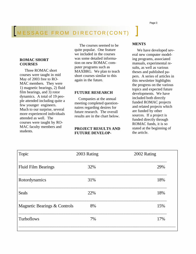
Topic 2003 Rating 2002 Rating ____________________________________________________________________________________
Fluid Film Bearings 32% 29% ____________________________________________________________________________________
Rotordynamics 31% 18% ____________________________________________________________________________________
Seals 22% 18% ____________________________________________________________________________________
Magnetic Bearings & Controls 8% 15% ____________________________________________________________________________________
Turboflows 7% 17% _________________________________________________________________________________________
ROMAC SHORT COURSES
Three ROMAC short courses were taught in mid May of 2003 free to RO-MAC members. They were 1) magnetic bearings, 2) fluid film bearings, and 3) rotor dynamics. A total of 19 peo-ple attended including quite a few younger engineers. Much to our surprise, several more experienced individuals attended as well. The courses were taught by RO-MAC faculty members and students.
The courses seemed to be quite popular. One feature we included in the courses was some detailed informa-tion on new ROMAC com-puter programs such as MAXBRG. We plan to teach short courses similar to this again in the future.
FUTURE RESEARCH
Companies at the annual meeting completed question-naires regarding desires for future research. The overall results are in the chart below.
PROJECT RESULTS AND FUTURE DEVELOP-
MENTS
We have developed sev-eral new computer model-ing programs, associated manuals, experimental re-sults, as well as various theses and published pa-pers. A series of articles in this newsletter highlights the progress on the various topics and expected future developments. We have included both directly funded ROMAC projects and related projects which are funded by other sources. If a project is funded directly through ROMAC funds, it is so stated at the beginning of the article.
Page 3
M E S S A G E F R O M D I R E C T O R ( C O N T )

Initial Values
Pad Pressure
Pad Tilt Angle
Journal Position
Film & Pad Temperature
Journal Temperature
Inlet Temperature
Deformations
Output
HD
THD
TEHD
Student: Minhui He
Advisors: Paul Allaire
Project Start Date: September 1996
Report Number: 458
Funding: ROMAC
Project Objective:
Fluid film journal bearings are widely used in rotating ma-chinery and their modeling is critical to machine design and analysis. First, the bearings’ stiffness and damping greatly affect a machine’s rotor dy-namics. Second, some bearing parameters, such as minimum film thickness and maximum temperature, are very impor-tant concerns for reliable op-eration. The objective of this project is to develop a state of the art thermo-elasto-hydrodynamic (TEHD) algo-rithm for industrial journal bearing analysis.
Many advanced methods are utilized throughout the modeling process. The pres-sure is calculated from the generalized Reynolds equation that includes radial viscosity variation. A special form of the two-dimensional energy equa-tion was developed for MAXBRG to achieve compu-tational efficiency and broad capability. The differential equations are solved by the finite element method and the turbulent effects are handled automatically. Pad temperature is calculated by a coupled film-pad approach that im-
proves numerical robustness. Pad elasticity is modeled by a two-dimensional finite element method. The deformations of journal, shell and pivot are all taken into account.
This comprehensive algo-rithm can be used to analyze directly lubricated bearings (inlet groove or spray bar) as well as conventional fixed ge-ometry and tilting pad bearings. Pressure dam bearings can also be analyzed with an adiabatic thermal model. In addition to the usual flooded lubrication condition, the bearings can be modeled under starvation, high ambient pressure or axial flow situations. Moreover, the algo-rithm allows great flexibility to suit different analytical needs. For example, a user can choose isoviscous analysis, or include either adiabatic or full thermal effects; the pads may have dif-ferent axial lengths or inlet ta-pers.
Progress in the Past Year:
The computer code MAXBRG that implements this algorithm was finished and the version 1.0 was released on July 1, 2003. Specifically in the past year, the pressure dam bearing was added in the analysis; the models for the conventional bearings under flooded condi-tion were extensively validated through comparisons with test data; the directly lubrication, starvation and other special flow models were preliminarily verified with good results; a few
corrections and updates were made according to the com-ments from users. The complete dissertation, a user’s manual and the code are now available from ROMAC.
Future Work:
Because of high demand from the ROMAC members (all companies at the meeting re-quested this), the second version is currently under development. Based on the survey at the an-nual meeting of 2003, several features will be added to MAXBRG, including hydro-static bearings, hydro-lift pocket effects, a second groove mixing model, and improved turbulence and starvation models. The new version is expected to be re-leased next summer. Mean-while, we are collecting feed-back and refining the code. Your input is very important and highly appreciated.
T E H D A N A L Y S I S O F F L U I D F I L M J O U R N A L B E A R I N G S ( C O M P U T E R C O D E M A X B R G )
Page 4 B E A R I N G S A N D S E A L S

B E A R I N G S A N D S E A L S
Student: Jie Zhou Advisors: Paul Allaire Project Start Date: Sept 2000 Funding: ROMAC Project Objectives:
LABY4 is a new gas laby-rinth seal analysis program under development. It will replace the current code LABY3. You may recall that LABY3 gives out reasonably good results for cross coupled damping dynamic coefficients but not-so-good other dynamic coefficients of stiffness and direct damping. The new key approach is to use three control volumes, following a method developed by Prof. Nordmann from Germany, to a better model the fluid stresses, forces and velocity of the flow field in the seals. Tascflow, a 3-D computational fluid flow code from AEA, is being used to determine the flow properties, such as the control volume velocity and pressures as well as suitable boundary condi-
tions to obtain a better flow de-scription for the three control volumes in each industrial laby-rinth seal configuration.
Progress in the past year:
The set of equations to de-scribe the flow in labyrinth seals has been obtained. A di-mensionless analysis of the dif-ferential equation primary flow equations and a perturbation of these equations were developed. A preliminary computer pro-gram has been written for the set of differential equations. The initial version of LABY4 works now. Before a test ver-sion to some industrial firms can be delivered, more develop-ment on the program stability and accuracy are underway to that ensure that all current avail-able experimental data sets are reasonably well modeled by the code.
At this time, we are trying to understand the flow in labyrinth seals more accurately. Our
current series of CFD simula-tions will focus on a 3D eccen-tric seal model. Some key pa-rameters used in three-control-volume method, such the ratio between the second and third control volume axial velocity, and boundary conditions such as inlet loss coefficient, exit recovery coefficient and land loss coefficient are expected to improve with detailed modeling capability from Tascflow. This will allow us to improve LABY4.
maximum testing speed from 2250 rpm to 7840 rpm. Up-dates included, overhaul of lu-brication system to handle high flow rates, sensor and load cell updates, and replacement of journal support bearings with high precision higher speed ball bearings.
Basically the test rig that was initiated about 20 years ago has reached its limits. Specifi-
Student: TBD
Advisors: Ron Flack, Lloyd Barrett, and Eric Maslen
Funding: ROMAC
Over the past years sig-nificant advances have been made on the ROMAC fluid film bearing test rig. For example, redesign work and updating of hardware and sensors led to an increase in
cally, static testing at journal speeds up to 7840 rpm has occurred (8000 rpm is the limit due to the drive timing belt) and dynamic testing is limited to 4900 rpm (due to shakers which are over heat-ing except for short tests). The maximum static load is 1000 lb f and dynamic loads are limited to 150 lb f. Fur-thermore, testing at higher speeds may be difficult due
L A B Y R I N T H G A S S E A L CO D E / P R O G R A M D E V E L O P M E N T
N E W F L U I D F I L M B E A R I N G T E S T R I G
Page 5

to structural resonances (there are several at lower speeds but have been out of the vi-cinities of testing speeds). Specifically, the stinger has resonances above 5000 cpm. The current design also re-quires the operator to be in the test cell for initial align-ment – at higher speeds this becomes a safety hazard. If the rig were to be run at higher speeds, static and dy-namic loading devices as well as load cells would have to be replaced (very expensive), the structure would have to be re-designed, and an out-of-test-cell alignment procedure would have to be developed. All of the above have forced the lab to seriously consider the next generation of test rig.
One configuration under consideration is a twin mag-netic bearing excitation sys-tem, similar to the new RO-MAC rotordynamic stability test rig and similar to the smaller scale bearing test rig at Universität Darmstadt and headed by Dr. Professor R. Nordmann. The design re-tains single bearing setup of current test rig, but the rigid mounting of fluid film bear-ing eliminates alignment con-cerns. The rig would be driven by high speed electric motor with VFD. The mag-netic “bearings” would load the test bearing both statically and dynamically. They
would act as load cells and the mo-tion sensors would be an integral part of the system. The use of these “bearings” would allow the rig to be much smaller and concise and would eliminate many of the resonances.
Design specifics would be to test bearings at least 3 in in diame-ter up to speeds of at least 12000 rpm and up to large eccentricity ratios. Tilt pad and other bearings will be tested. At this point a de-tailed optimization study is needed. Namely, the speed and or load need maximized (one cannot get both for dynamic testing). Re-quired loads and sizes of the mag-netic bearings need to be deter-mined. The specific eccentricity range needs to be set. And a full dynamic analysis of the possible rig needs to be done including static and dynamic constraints which dictates journal, bearing, and magnetic bearing diameters and masses.
A component analysis will be needed as very few of the compo-nents on the current rig will trans-fer. This will be a dedicated effort by a new graduate student, hope-fully starting in January. Included in the analyses are: Magnetic Bear-ing System (Two Magnetic Bear-ings, Lamination Stacks, Custom Controller, Computer Interface Boards), Fluid Film Bearing Sys-tem (FFB split housing, Test bear-ing, Oil seals), Drive System (High Speed Motor (~25 hp), Variable Frequency Drive, High Speed Cou-
pling), Lubrication System (Lube Oil Supply Pump, Electric Heater, Shell and Tube Counter Flow Heat Exchanger, Flow Me-ter with automatic flow control), Instrumentation (Proximity Probes, Hall Sensors, Thermo-couples, A/D Boards), Com-puters/Accessories (Magnetic Bearing Control Computer, Data Acquisition Computer).
With a project this large member interest is imperative. Input from interested members must be incorporated into any further design, in order to satisfy the current industrial demands several companies have already made suggestions. Furthermore, financial support and “donations” will be necessary. Again, several companies have already volunteered with hard-ware contributions and we will look for this to continue.
N E W F L U I D F I L M B E A R I N G T E S T R I G ( C O N T . )
“One
configuration
under
consideration is
a twin magnetic
bearing
excitation
system”
Page 6 B E A R I N G S A N D S E A L S

Student: Jack Zhou (Temporary)
Faculty: Paul Allaire
Funding: ROMAC
Rolling element bearing stiffness and damping proper-ties is a topic that many RO-MAC companies are inter-ested in. However, ROMAC faculty members have not conducted research in this area before. In our ROMAC Annual Meeting last summer, half of the companies present voted for us to conduct re-search on the topic and it is thought that a number of other companies that were not would like this work. This number of votes is about the same as several other topics such as the work on the ro-tor/bearing stability test rig and the high speed bearing rig. A preliminary assess-ment of codes such as the JB Jones code indicates that the currently available rolling element bearing codes to not meet the needs of ROMAC companies.
Paul Allaire is willing to undertake research on the topic to develop a rolling ele-ment modeling code over the next few years with suitable supporting staff. Part of the analysis involves the operat-ing conditions of the rolling
element bearings where some recent research has been found. Recent research by Bercea, Nelias, and Cavallaro [2000] in laboratories Romania and France discussed the equilibrium prob-lem of double-row rolling bear-ings. Zupan and Prebil [2001] of a university in Ankara Turkey, discussed carrying angle and carrying capacity of large single row ball bearings.
Other work is more con-cerned with stiffness and damp-ing properties with some exam-ple work obtained from the lit-erature. Dietl, Wensing, and van Nijen [2000] conducted an ex-perimental and theoretical study of damping in rolling element bearings at SKF in the Nether-lands. Wensing and van Nijen [2001] developed modeling of the stiffness and damping of roll-ing bearings. Akturk [2003] of Gazi University in Turkey deter-mined the effects of preload and number of rolling elements on angular contact ball bearing stiff-ness and how it affects rotor natural frequency. An SKF engi-neer in the US has provided Paul with a tutorial on rolling element bearings to get us started and SKF is interested in cooperating with us on better understanding of rolling element bearing prop-erties.
As this is a new area for us, we will have to work with the companies which desire this new code to determine priorities on
which bearing types and other details of the bearing analysis that need to be carried out. We hope that work in this area will bring in several new ROMAC members who need this type of analysis.
R O L L I N G E L E M E N T B E A R I N G S T I F F N E S S A N D D A M P I N G P R E D I C T I O N S
Page 7 BEARINGS AND SEALS
“Paul Allaire is willing to undertake research on the topic to develop a rolling element modeling code over the next few years….”

ROTORDYNAMICS
Student: C. Hunter Cloud
Advisors: Lloyd Barrett, Eric Maslen
Project Start Date: January 1990
Funding: ROMAC/ExxonMobil/Petrobras
Project Objectives:
With stability of turbo-machinery being a major con-cern, this project is focused on avoiding these problems in the future by conducting research in the following two areas:
A. Determining test tech-niques which are suitable for accurately measuring the sta-bility of a rotor/bearing sys-tem.
B. Examining how tilting pad bearing characteristics and common phenomena such as unbalance influence the actual stability levels and thresholds versus modeling predictions.
To investigate these issues, a test rig is being constructed which will simulate the dy-namic behavior of many types of turbomachinery such as pumps, compressors, and steam turbines. Magnetic ac-tuators will supply excitations in the form of destabilizing cross-coupled stiffness and non-synchronous forcing (sine sweep, impulse, etc). Several bearing designs will be tested with the base design being a 5 pad, load between pad bearing with L/D = 0.75, 0.3 preload, center offset rocker back piv-
ots.
Progress in the Past Year:
Test rig has achieved 10,000 rpm with bearing overall vibra-tion levels of less than 0.25 mils p-p. The data acquisition system for basic machinery measure-ments such as orbits, Bode plots and spectrums is almost fully operational. Current efforts are focused on the magnetic actuator cross-coupling and excitation control system development and
commissioning to make the rig fully operational for stability testing. Analytical efforts are focused on evaluating which system identification/modal analysis techniques are most appropriate for measuring a rotor’s stability level. In con-junction, software is being de-veloped to implement these techniques on the test rig.
R O T A T I N G M A C H I N E R Y S T A B I L I T Y T E S T R I G
Page 8 ROTORDYNAMICS
ROTORDYNAMICS
“The underlying idea is to introduce localized modifications to analytic rotordynamic models to make them match experimental data.”
Student: Qingyu(Flofish) Wang Advisor: Eric Maslen Project Start Date: January 2000 Report Number: 432, 444 Funding: ROMAC Project Objectives:
The ultimate objective of this work is to develop a reasonably automated mechanism for correct-ing engineering models of rotor-dynamic systems to better match experimental data for real ma-chines. An important feature of the approach pursued here is that it can capture dynamic effects completely missed in the model, like foundation dynamics. Thus it could be used to better model ex-isting machines. We refer to the method as model reconciliation (MR). The underlying idea is to introduce localized modifications to analytic rotordynamic models to make them match experimental data. When finally developed, the method should have the following properties:
1) It should permit extrapolation: a corrected the transfer function from one set of system inputs to one set of outputs should imply an accurate transfer function from another set of inputs to another set of outputs. This means, for in-stance, that correcting the model using data from an instrumented hammer and accelerometers would improve the prediction of response at a seal location to exci-tation at unbalance locations.
2) The method should account for uncertainties in the data, the finite frequency range of the data, engi-neering assumptions about the
model, and engineering assump-tions about where error or unmod-elled dynamics are likely to enter the model.
The work is central to any engi-neering process where some un-known machine parameter needs to be estimated from experimental data. For instance, in Hunter Cloud's work, we seek to identify bearing properties from forced re-sponse data - a process which neatly falls under the rubric of model reconciliation. Indeed, a significant question that Hunter raises is whether the extracted model should be synchronously reduced or full tilt pad coefficient - a dynamically more complex model. MR can address this ques-tion directly because it doesn't as-sume, a priori, that the bearing dynamics have any particular char-acter (K and C, for instance) but instead produces a transfer func-tion representation of the bearing dynamics. This transfer function can be interpreted either as a close fit K and C or as a more complex dynamic system (full tilt pad model).
Progress in the Past Year:
In the past year, we proposed a "robust model reconciliation" (RMR) method which incorporates the effects of the experimental uncertainty(bounded, spectrally characterized noise). We also de-veloped a method to examine the validity of the reconciliation proc-ess, which uses extra data as a ref-erence to compare with the data produced by the reconciled model.
Both simulated data and ex-perimental data have been used to demonstrate the results of the method. The error model permits the synthesis to ignore spurious features of the identi-fied model, thereby producing more reasonable results. Fi-nally, a recent development promises to greatly reduce the computational complexity of the method, resulting in a much more reliable numerical tool. The work is designed to be useful to Romac companies and we request your input in the development of the meth-ods.
M O D E L R E C O N C I L I A T I O N
Page 9 ROTORDYNAMICS

Student: Guoxin Li and Bin Huang
Advisor: Paul Allaire and Zongli Lin
Project Start Data: January 2002
Funding: ROMAC
Project Objectives:
Since the 1950s balanc-ing has been an important technology for engineers concerned with synchronous vibration problems. While the technology has im-proved over the years, there is still no efficient computer program to solve some of the basic balancing prob-lems, such as the minmax balancing problem. In many cases, the conventional least squares method of balancing is not optimum for balanc-ing high-speed flexible ro-tors. The objective of this research is to develop a new generalized approach to ro-tor balancing with a convex optimization technique. This formulation not only solves the minmax balancing prob-lem, i.e. the maximum vi-bration amplitude is mini-mized, but also allows bal-ancers to deal with various kinds of practical con-straints and data uncertainty.
Furthermore, this formulation can be extended to a unified approach in which the modal trial weight distribution is obtained by solving inequality constraints.
Progress in the Past Year:
A beta version of the new ROMAC balancing code, BALOPT, is complete. A friendly user interface using Script Editor is developed. This version of BALOPT contains the following basic functions: influence coeffi-cient estimation, run out com-pensation, weighted minmax, weighted least squares, cor-rection weight constraints and orbit constraints. The code is being tested numerically. The beta version is also being verified by some of the RO-MAC members who partici-pated in this project.
Future Work:
BALOPT will be tested both numerically and experi-mentally on the laboratory test rigs and the industrial rotors. New functions such as the robust balancing, stochas-tic influence coefficient esti-mation and unified approach with modal balancing as well as the pre-processing and post-processing functions will
be added. Different solvers will be tested, and the user interface will be enhanced. Members are encouraged to try the beta version and feed-back is needed to improve the code. The final version will be released in June 2004 be-fore the annual meeting.
B A L O P T — N E W B A L A N C I N G C O D E
Page 10 ROTORDYNAMICS
“A beta version of the new
ROMAC balancing code,
BALOPT, is complete”
FLUID FLOWS
Student: Eric Buskirk
Advisors: Eric Maslen and Ron Flack
Funding: ROMAC
Project Objectives:
This test facility has several objectives in study of high speed centrifugal compres-sors. The first is to collect bearing load data for on- and off-design conditions. This data will be used to validate and improve computational tools. Secondly, testing will investigate the sensitivity of flow instabilities to adjusting compressor parameters (tip clearance, volute size, etc). The last objective is to develop an active surge control algo-rithm to be used in industrial scale centrifugal compressors. This control scheme will modulate the tip clearance to
stabilize surge (see Surge Stabi-lization in Centrifugal Com-pressors).
The test rig will incorporate two radial active magnetic bear-ings (AMB) and one thrust AMB to constrain five degrees of freedom. The AMBs will provide a direct measurement of the bearing forces by measuring the coil currents. Later work will include mounting flux sen-sors on the pole faces to obtain more precise force measure-ments at the bearing locations. In addition, the AMB will allow active manipulation of the rotor position and, hence, impeller tip clearance.
Progress in the last year:
All design work is complete for test rig. All machine parts have been released to machine shops. The impel-
ler/volute/diffusser set, sup-plied by Kobe Steel, has been completed and tested. We have started to move equip-ment into our new test facil-ity. The machine founda-tion has been installed, as have most of the utility ser-vices. Instrumentation design for the test facility has been completed and purchase of the required transducers has been initiated. A data acqui-sition system has been speci-fied and bids are currently in evaluation. Testing is ex-pected to start by the begin-ning of 2004.
ited at low mass flow rates by the onset of surge. Magnetic bearings offer the potential for active control of flow instabili-ties, potentially mitigating the hazards associated with opera-tion near the nominal surge line. For compressors with un-shrouded impellers, this capabil-ity is highly dependent on the sensitivity of the compressor
Student: Dorsa Sanadgol
Advisors: Eric Maslen and Ron Flack
Project Start Date: Fall 2001
Funding: ROMAC
Project Objectives:
The safe range of operation in compressors is usually lim-
characteristics to blade tip clearance. If the position of the shaft can be actuated with sufficient authority and speed, the induced pressure modula-tion makes control of surge possible. Use of axial motion in centrifugal compressors distinguishes this work from related studies which have examined radial motion of
H I G H S P E E D C O M P R E S S O R T E S T F A C I L I T Y
S U R G E S T A B I L I Z A T I O N I N C E N T R I F U G A L C O M P R E S S O R S
Page 11 FLUID FLOWS

FLUID FLOWS
axial compressors. The ability to modulate the mean tip clear-ance, rather than to induce a circumferentially periodic per-turbation is a significant advan-tage of our approach. Ulti-mately, the methods developed in this project will be tested on the centrifugal compressor test stand presently under develop-ment at ROMAC.
Progress in the past year:
A one dimensional incom-pressible flow model including the effects of tip clearance variation on the compressor
characteristic has been derived. Using a proper Lyapunov func-tion a stability condition for mass flow feedback gain was also derived. Due to impracti-calities of mass flow measure-ments, subsequent research has focused on applying different estimation techniques to substi-tute pressure measurements for direct mass flow measurement. Among the nonlinear estima-tors, extended Kalman filter (EKF) method is used because of its high performance and ro-bustness. Simulation results
show that EKF is able of ac-curately estimating the true mass flow rates. These esti-mates are further used as the input to the controller. Results from simulation of this con-trol scheme show that mass flow and pressure oscillations associated with compressor surge can be quickly sup-pressed and the stable operat-ing range of the compressor can be increased significantly with reasonable control au-thority.
S U R G E S T A B I L I Z A T I O N I N C E N T R I F U G A L C O M P R E S S O R S ( C O N T . )
E F F E C T O F R E Y N O L D S N U M B E R O N P E R F O R M A N C E O F A
S M A L L C E N T R I F U G A L P U M P
els of a small centrifugal pump, which has an impeller diameter of 46 mm with a log spiral vo-lute. In the experiments, the Head-Capacity curves were de-termined for speeds between 500 and 3000 rpm and for two fluids with different viscosities. Design point Reynolds numbers ranged from 90 to 2800. Re-sults showed that lower Rey-nolds number flows did not ad-here to conventional pump af-finity laws, whereas higher Reynolds number flows scale very effectively according to traditional pump affinity laws. The numerical study consisted
of comparing the generated head and internal flow field of the pump scaled based on tra-ditional affinity laws with and without consideration of the Reynolds number. Like the experimental results, the nu-merical simulations indicate that consideration of the Rey-nolds number is necessary to insure accurate scaling in this small pump.
Students- Steven Day, Phillip Lemire
Advisors- Ron Flack, Jim McDaniel
Funding: None
Project Objective:
A study of a small centrifu-gal pump has been made to address the effectiveness of traditional pump affinity laws and the influence that viscous effects, as characterized by the Reynolds number, have on the pump performance. This was investigated both experimen-tally and numerically on mod-
Page 12 FLUID FLOWS

MAGNETIC BEARINGS
Student: Dominick Montie
Advisors: Eric Maslen and Tetsuya Iwasaki
Reports: #482, #387
Funding: None
Project objective:
Self sensing magnetic bear-ings offer the potential advan-tage of reducing hardware cost and complexity in commercial AMB systems. Experience with this technology over the past 15 years has been modest, suggesting that the achievable performance of self sensing AMB’s is likely to be poor relative to position sensed sys-tems. The goal of this project has been to develop a commer-cially feasible approach to self sensing that answers this con-cern of poor relative perform-ance.
To realize this goal, the project has explored a specific paradigm for exploiting ampli-fier induced switching ripple in the AMB coils to estimate air gap dimension. This explora-tion has followed numerous lines including electrical reali-zation as well as sensitivity to hysteresis, eddy currents, mag-netic saturation, and other sources of uncertain gain in the system. Numerous experi-ments have been conducted
including physical levitation of a rotor in self sensing AMB’s at speeds up to 60,000 RPM and simulation studies aimed at revealing details of hystere-sis sensitivity.
The main findings of this work are that the paradigm developed at ROMAC is vi-able and that sensing resolu-tion can be quite fine: on the order of 0.04 mils with high permeability stator materials. Further, rough measures of relative stability suggest that our sensing technique can yield a system with nearly as high gain margins as are real-ized with eddy current sensors.
Progress in the past year:
In the past year, a formal analysis framework for study-ing the stability robustness advantages of exploiting switching ripple was devel-oped and explored. The excit-ing conclusion of this work is the observation that self sens-ing AMB’s are not, in fact, fundamentally touchy and there is emerging technology to realize very robust systems. The bulk of the technical de-tails of the analysis and inter-pretation of the results are too cumbersome to present here in the newsletter, but the main
finding is that tolerable gain uncertainty can typically be increased by a factor of more than 10 by properly exploit-ing switching ripple. This means that, if sufficient lev-els of switching ripple are acceptable in a given AMB system, then it will be very reasonable and commercially viable to implement the sys-tem as self sensing.
P E R F O R M A N C E L I M I T A T I O N S A N D S E L F - S E N S I N G M A G N E T I C B E A R I N G S
Page 13 MAGNETIC BEARINGS

MAGNETIC BEARINGS
11
piecewise m-synthesis design the operating speed range is divided into several regions. Each controller is designed to cover a certain speed range where the gyroscopic effects are treated as uncertainties. Overall control is implemented by switching between controllers as speed varies from one region to another. A bumpless transfer scheme is implemented to guar-antee smooth transition between controllers. In the LPV design the gain scheduling problem is formulated in the context of convex semidefinite program-ming by linear matrix inequali-ties (LMIs). The LPV controller is obtained by solving the LMIs using interior point methods.
A test rig was constructed as a platform for investigating of different controllers. First, an accurate nominal model includ-ing the substructure modes was developed from physical laws and refined by experimental data. An uncertainty representa-tion and a performance criterion
were developed for the model AMB system. The influence of gyroscopic effects on the stabil-ity and performance of AMB system under a MIMO control-ler was analyzed.
Progress in the Past Year: We tested different control-lers. The results were used to validate the model and the con-trol design. Of special interest is the control of the flexible rotor modes and substructure dynam-ics. The objective is to add more damping into the flexible modes while minimize the force transmitted to the substructure. The work will be completed this year, and the results will be re-leased in ROMAC report.
C O N T R O L O F H I G H S P E E D G Y R O S C O P I C R O T O R S W I T H A M B S
Page 14 MAGNETIC BEARINGS
Student: Guoxin Li
Advisor: Paul Allaire, Zonlgi Lin
Project Start Date: January 2000
Funding: None
Project Objectives: For some rotors, such as fly-wheel rotors, gyroscopic effects are significant due to the high polar inertia as compared to bending inertia as well as the high operating speeds. Control of a strongly gyroscopic rotor over a wide speed range with magnetic bearings is a very challenging problem. Two dominant issues must be ad-dressed in the control design. First, the dynamics of the rotor vary with the operating speed; a single linear time invariant con-troller often cannot stabilize the system over the entire operating range. Second, high robustness is required to handle the uncer-tainty of the rotating system stiffness, damping and other properties. Additionally, gyro-scopic effects couple the two radial directions and the system natural frequencies are split into forward and backward modes. Advanced multi-variable robust optimal controls, H¥ and m-synthesis, provide systematic tools to achieve system robust-ness. To address the speed de-pendent dynamics, two ap-proaches are being investigated: the piecewise m-synthesis and the gain scheduled control, in particular, the linear parameter varying (LPV) approach. In
MAGNETIC BEARINGS
D Y N A M I C S A N D C O N T R O L O F N O N - L A M I N A T E D M A G N E T I C L E V I T A T I O N S Y S T E M S
the magnetization curve produced frequency re-sponses very similar to those generated from dy-namic tests on the magnetic actuator.
An analytic model for a non- laminated cylindrical magnetic actuator includ-ing eddy current effects was developed. Due to the complexity of this com-plete analytic model, a sim-plified model was given. Both the complete and the simplified models are ex-plicitly dependent on the actuator material and geo-metric properties. Thus, the influence of each of the actuator properties on its performance can be easily calculated. Comparison of the frequency responses of the two analytic models to that resulting from finite element analysis demon-strates good accuracy for a wide range of material and geometric properties. The
analytical modeling ap-proach employed is being applied to non- laminated magnetic actuators of other geometries, such as C type, to generate accurate ana-lytic models for these ac-tuators.
Page 15
Student: Lei Zhu
Advisor: Carl Knospe
Project Start Date:
July 2000
Funding: NSF
Project Objectives:
The objectives of this pro-ject are to develop control algorithms that provide stiff, high servo bandwidth, mag-netic suspension for systems with non- laminated actuators, and to quantify the perform-ance limitations for these sys-tems.
Progress in the Past Year:
Experiments for measur-ing the material properties of the magnetic alloy used to build the non- laminated mag-netic actuator have been car-ried out. The magnetization curve, and major and minor hysteresis loops for the mag-netic alloy have been plotted from the experimental data. Finite element analysis using
MAGNETIC BEARINGS
“The objectives of this project are to develop control algorithms that provide stiff, high servo bandwidth, magnetic suspension for systems with non-laminated actuators”

Student: Min Chen
Advisor: Carl Knospe
Project Start Date: Septem-ber 1999
Funding: None
Project Objectives:
High speed machining, which combined with higher spindle speed, machine feedrates and greater depth of cut, increases the metal removal rate and productiv-ity. However, this aggressive cutting operation makes “chatter” a more significant concern. Self-excited chatter adversely affects machining operations by causing tool failure, increased tool wear, and scrapped parts. Most current techniques are to al-ter machining conditions (e.g. spindle speed) to avoid the occurrence of chatter.
Active magnetic bearings (AMBs) provide a new solu-tion for chatter free high speed machining, due to its active control capability. Advanced control techniques can be designed and em-ployed in AMBs, so as to optimize the tool/ spindle dynamics catering to current cutting conditions. Com-pared to conventional ap-proaches, AMB based chat-ter control is more flexible
and can achieve greater depth of cut in machining operations.
Progress in the Past Year:
Advanced control design techniques require an accurate mathematical model of the cut-ting process. In the past year, a new experimental approach to identify the cutting dynamics was proposed. This method treats the problem as a closed-loop gray-box identification case and is based upon spectral analysis and least squares esti-mation. Active magnetic bear-ing is employed both to excite the system and to increase the tool’s damping. The key of this method is to break the inherent time delay feed back loop in machining process by limiting the observation period to less than one workpiece revolution. A relationship between cutting dynamics and depth of cut at certain machining conditions has been identified using this new method. The models built could be used to predict ma-chining stability and guide tool controller design.
Both speed-independent and speed-dependent controllers have been synthesized and im-plemented in AMB system. Speed-independent controllers optimize the tool/spindle dy-namics at the worst case cut-ting speeds, while the speed-dependent controllers optimize
the tool/spindle dynamics at one specified cutting speed. They can be used in differ-ent cutting applications.
A controller switching technique has been investi-gated and implemented in the dSPACE control board to achieve bumpless transfer between controllers. This technique can be used to select controllers automati-cally or manually according to different cutting condi-tions without affecting the current cutting operation.
M A C H I N I N G C H A T T E R C O N T R O L W I T H A C T I V E M A G N E T I C B E A R I N G
Page 16 MAGNETIC BEARINGS
A controller switching
technique has been
investigated and
implemented in the
dSPACE control board to
achieve bumpless
transfer between
controllers”
SOFTWARE HIGHLIGHTS
U TS
U TS
L O W
L O W
ES L
ES L
T im e (s e c )
Ele
men
tStr
ess
(psi
)
0 1 0 2 0
-8 0 0 0 0
-6 0 0 0 0
-4 0 0 0 0
-2 0 0 0 0
0
2 0 0 0 0
4 0 0 0 0
6 0 0 0 0
8 0 0 0 0
El e me n t 2 2 1 1 0 %
T OR P L O T3 ,M a y 0 6 , 2 0 0 3 : V e r sio n 2 .2
R u n t im e is W e d Ma y 0 7 2 1 : 4 9 :4 9 2 0 0 3
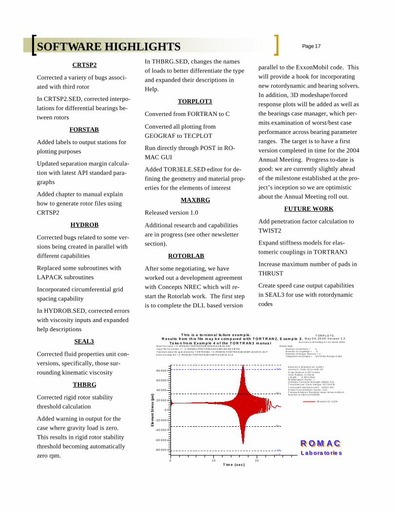
T his is a to rs ion a l fa ilure e x a m p le .R e s ul ts fr om th is file m a y b e c om p a re d w ith T O R T R AN 2 , E xa m p le 3 .
Ta ke n fro m E x a m p le 4 o f the T O R T R AN 3 m a nua lM a in f il e n a me = C : /R O M AC / TO R TR A N 3 /E XA M PL E S /E X4 . D ATI n p u t f ile f o r s e c tio n 1 = C :/ R O MA C /TO R T R AN 3 / EX A MP L ES / EX 4 .M O DT ra n s ie n t d a t a f ile (g en era t e d b y T O R TR A N3 ) = C :/ R O M AC /T O R TR A N 3 /E XA MP L E S/ E X4 . O U TE le m e n t d a ta fil e = C : /R O M AC / TO R TR A N 3 /E X AM PL E S /E X4 .E L E
G lo b a l d a ta :N u m b e r o f s ec t io n s = 1N u m b e r o f c o u p lin g s = 0N u m b e r o f to rq u e so u rc e s = 2I n te g ra t io n t e c h n iq u e = 4 t h O rd e r R u n g e -K u tt a
E le m e n t 1 (E le me n t 2 2 1 1 0 % ) :s e c ti o n 1 , n o d e 2 2 t o n o d e 2 3O u te r R a d i u s: 3 . 9 3 7 in ch e sI n n e r R a d iu s : 0 i n ch esL en g th : 6 . 8 9 in ch e sM u lt ip li ca t io n Fa c to r : 1U l ti ma t e To rs io n a l St re n g th : 9 0 8 0 0 P SIT o rsi o n a l L o w C yc le Fa ti g u e : 8 1 7 2 0 P SIT o rsi o n a l E n d u ra n c e L im it : 3 2 9 1 5 PS IS t res s C o n c e n t ra t io n Fa c to r : 3 .1 5F a ti q u e A n a ly si s: R e s id u a l me a n st re ss m e th o d .N u m b e r o f s ta r t s: 0 .4 8 2 0 6 9
R O M A CR O M A CL a b ora to rie sL a b ora to rie s
CRTSP2
Corrected a variety of bugs associ-ated with third rotor
In CRTSP2.SED, corrected interpo-lations for differential bearings be-tween rotors
FORSTAB
Added labels to output stations for plotting purposes
Updated separation margin calcula-tion with latest API standard para-graphs
Added chapter to manual explain how to generate rotor files using CRTSP2
HYDROB
Corrected bugs related to some ver-sions being created in parallel with different capabilities
Replaced some subroutines with LAPACK subroutines
Incorporated circumferential grid spacing capability
In HYDROB.SED, corrected errors with viscosity inputs and expanded help descriptions
SEAL3
Corrected fluid properties unit con-versions, specifically, those sur-rounding kinematic viscosity
THBRG
Corrected rigid rotor stability threshold calculation
Added warning in output for the case where gravity load is zero. This results in rigid rotor stability threshold becoming automatically zero rpm.
In THBRG.SED, changes the names of loads to better differentiate the type and expanded their descriptions in Help.
TORPLOT3
Converted from FORTRAN to C
Converted all plotting from GEOGRAF to TECPLOT
Run directly through POST in RO-MAC GUI
Added TOR3ELE.SED editor for de-fining the geometry and material prop-erties for the elements of interest
MAXBRG
Released version 1.0
Additional research and capabilities are in progress (see other newsletter section).
ROTORLAB
After some negotiating, we have worked out a development agreement with Concepts NREC which will re-start the Rotorlab work. The first step is to complete the DLL based version
parallel to the ExxonMobil code. This will provide a hook for incorporating new rotordynamic and bearing solvers. In addition, 3D modeshape/forced response plots will be added as well as the bearings case manager, which per-mits examination of worst/best case performance across bearing parameter ranges. The target is to have a first version completed in time for the 2004 Annual Meeting. Progress to-date is good: we are currently slightly ahead of the milestone established at the pro-ject’s inception so we are optimistic about the Annual Meeting roll out.
FUTURE WORK
Add penetration factor calculation to TWIST2
Expand stiffness models for elas-tomeric couplings in TORTRAN3
Increase maximum number of pads in THRUST
Create speed case output capabilities in SEAL3 for use with rotordynamic codes
Page 17 SOFTWARE HIGHLIGHTS

2004 Romac
Annual
Meeting
6/6/04-
6/9/04
ting as well as conven-ience to many busi-ness, shops and attrac-tions. The hotel pro-vides free shuttle to and from the Char-lottesville airport, as well as to some UVA locations.
The meeting will begin with a welcome reception on Sunday afternoon. Lunch and breaks will be pro-
Charlottesville, VA
June 6 – 9, 2004
The 2004 Annual Meeting will be held in Charlottesville, VA at the DoubleTree Hotel (www.charlottesville.doubletree.com) at a nightly rate of $60.00 sin-gle/double room plus taxes. The DoubleTree is located on 29North and offers an elegant set-
vided during the week, as well as a dinner buffet on Monday night. Registra-tion packets will be mailed out at the beginning of March. Details are also provided on our web at http://virginia.edu/romac/. Make plans now to attend the 2004 ROMAC Confer-ence!
Page 18
Students: Matthias Glauser, Sonna Patel, Amy Throck-morton, Alex Untariou, Yi Wu
Funding: National Institute of Health, Medforte Foundation
Faculty and Collaborators: Paul Allaire, Tingshu Hu, Wei Jiang, Ron Kipp (Kipp Engi-neering), Zongli Li, Scott Lim (Cardiologist), Paul Matherne (Cardiologist), Ben Peeler (Heart Surgeon), Don Olsen (Director: Utah Artificial Heart Institute), Xinwei Song, Curt Tribble (Heart Surgeon), Houston Wood
Faculty and Collaborators: Paul Allaire, Tingshu Hu, Wei Jiang, Ron Kipp (Kipp Engi-neering), Zongli Li, Scott Lim (Cardiologist), Paul Matherne (Cardiologist), Ben Peeler (Heart Surgeon), Don Olsen (Director: Utah Artificial Heart Institute), Xinwei Song, Curt Tribble (Heart Surgeon), Houston Wood
Our new prototype axial flow magnetically suspended artificial heart pump is now under construc-tion. It is intended for left ven-tricular assist in persons with con-gestive heart failure to work in par-allel with the diseased heart. It pumps at a design flow of 6 li-ter/min and produces a pressure rise of 100 mm Hg. It has dimen-sions of approximately 65 mm long by 35 mm in diameter. The axial flow pump has an inlet with 6 blades inducer, the impeller has 4 vanes and the diffuser has 3 vanes. The magnetic suspension system is composed of one permanent mag-net radial bearing, one active con-trol electromagnetic radial bearing and one permanent magnet thrust bearing. The rotor position sensors are Hall effect sensors used for both feedback to the active control bearing and flow control through estimating the pressure drop in the pump impeller.
It is expected that we will have the first few prototypes for testing in November or December of this year. A simulated cardiac test loop consisting of a pneumatic pulsatile
heart mock heart, fluid filled tubes modeling the veins and arteries, and an adjustable resis-tance to simulate states of resting (sleep), low level activity such as sitting upright, and higher level of activity such as walking. The pump will be tested for it's per-formance and reliability.
The past work on this project has been funded by the National Institute of Health over the past five years in a large grant funded through the Utah Artificial Heart Institute and UVA. A large grant application is pending with NIH for support of this project through the next five years. We expect to hear if the grant is funded early next year. We think we have a very good chance.
HEART PUMP
ANNUAL MEETING
gineering and the Department of Physics, and all but very large scale fabrication and assembly tasks can routinely be carried out in those shops. The University also maintains a well-staffed elec-tronics shop in the Department of Physics, the personnel of which are called upon as needed to assist with maintenance, repairs and calibration of our instrumentation.
Several of our most recent ac-quisitions have been in support the work on our instability and compressor test rigs. We are very grateful for the support of the in-dustrial members who have as-sisted with the equipment needs of those projects. In addition to that work, we’re also going through an assessment process aimed at defining the equipment that might be needed for the de-velopment of a high speed bear-ing test rig, and similar support from the industrial members would also be critical to seeing that project go forward.
With the changeover from 35 mm slide presentations to all elec-tronic ones, we chose this past Summer to apply to the Common-wealth of Virginia’s Equipment Trust Fund for matching funds to purchase two computer projec-tors, for use at the ROMAC An-nual Meeting and at our student seminars. As mentioned above, the Equipment Trust Fund pro-vides a 50% match against avail-able funds from sponsored re-search and other sources, thus
There are a number of mecha-nisms through which ROMAC obtains research instrumentation and other equipment for its labo-ratories. These include:
• Budgeted purchase using RO-MAC funds
• Budgeted purchase via a spon-sored research grant or contract
• Long-term loan from a mem-ber company or a national labo-ratory
• Donations of equipment from industry
• Purchase with 50% fund match via the Virginia Equip-ment Trust Fund
Equipment purchased via sponsored research contracts is typically titled to the University unless negotiated otherwise by the sponsor, and it often be-comes generally available to the whole ROMAC laboratory fol-lowing completion of the project for which it was obtained. We presently maintain a large and well-used collection of standard electronic test and measurement instruments, Bentley probes, vibration and acceleration sen-sors, and calibration devices. Our laboratory facilities include two benchtop areas that are given over to bread-boarding and circuit assembly, and we have a small in-house machine shop area as well. In addition, there are excellent shop facili-ties in both the Department of Mechanical and Aerospace En-
allowing significant leverage of our ROMAC equipment budget. We look for every opportunity to take advantage of this program for the benefit of our sponsors. Purchase requests made to it are ranked com-petitively by the University admini-stration, based on the need for each item, its cost, expected service life, etc. Several of our most generally useful instruments have been pro-cured in this way, including spec-trum analyzers, heavy duty power supplies, and so on.
It is our aim to ensure that all of the ROMAC research students al-ways have the instruments and equipment they need for their work. As in any busy enterprise, though, it sometimes happens that the most widely usefed items of test and measurement equipment are tied up on one project but nevertheless needed on another. Therefore, we do ask the member companies to keep us in mind when it comes to disposition of surplus equipment that might still have a useful service life. If you are going through any project close-downs or laboratory consolidations that might make such items available (eg., DVMs, wave-form generators, vibration sensors, oscilloscopes, etc.), please let us know. The ROMAC contact point for this is George T. Gillies, who can be reached at [email protected] or by calling (434)924-6235.
LABORATORY EQUIPMENT ACQUISITIONS

We are on the web!
www.virginia.edu/romac/
University of Virginia
Romac Lab 122 Engineer’s Way Charlottesville, VA 22904 Phone: (434)924-3292 FAX: (434) 982-2246
Special points of inter-est:
* Plans for Annual
Meeting now under
way
* Annual ROMAC Fee
unchanged for 2004
* New companies
joining Romac
* Software Highlights