roller compacted concrete manual for local government agencies
TRANSCRIPT

Roller Compacted Concrete Manual for Local Government Agencies
November 2010
TR-2-2010
Indiana LTAP Center Purdue University School of Civil Engineering Indiana LTAP Center 3000 Kent Avenue West Lafayette, Indiana 47906 Telephone: 765.494.2164 Toll Free in Indiana: 1.800.428.7639 Facsimile: 765.496.1176
This document is disseminated under the sponsorship of the Indiana LTAP Center at Purdue University in the interest of information exchange. Purdue University and the Indiana LTAP Center assume no liability for its contents or use thereof. Purdue University and the Indiana LTAP Center do not endorse products or manufacturers. Trademarks or manufacturers names may appear herein only because they are considered essential to the objective of this document. The contents of this report reflect the views of the authors, who are responsible for the facts and accuracy of the data presented herein. The contents do not necessarily reflect the official policy of Purdue University or the Indiana LTAP Center. This report does not constitute a standard, specification, or regulation.

1. Report No. TR-2-2010
21. No. of Pages: 113
22. Price: N/A
15. Supplementary Notes
17. Key Words: Roller Compacted Concrete, RCC, Roller Compacted Concrete Pavement, RCCP
18. Distribution Statement: No Restrictions
2. Government Acession No. 3. Recipient's Catalog No.
5. Report Date: November 17, 2010
6. Performing Organization Code:8. Performing Organization Report No.
4. Title and Subtitle: The Indiana Local Technical Assistance Program Roller Compacted Concrete Pavement Manual for Local Government Agencies
9. Performing Organization Name and Address: Purdue University School of Civil Engineering, Indiana Local Technical Assistance Program, 1435 Win-Hentschel Blvd., Suite B100, West Lafayette, Indiana 47906
12. Sponsoring Agency Name and Address
7. Author(s): Kyung-Joon Shin, PhD, Purdue University and Neal Carboneau, P.E., Purdue University, Indiana LTAP
Form DOT F 1700.7 (8-72)
10. Work Unit No.
11. Contract or Grant No.
13. Type of Report and Period Covered: Manual
14. Sponsoring Agency Code
Form DOT F 1700.7 (8-72) Reproduction of completed page authorized
19. Security Classif. (of this report): Unclassified
20. Security Classif. (of this page): Unclassified
16. Abstract: Interest in the use of Roller Compacted Concrete (RCC) pavement (RCCP) for local roads and streets has increased. The Indiana Local Technical Assistance Program (LTAP), which is a part of the Purdue University School of Civil Engineering, has developed this document to assist local agencies with the implementation of roller compacted concrete as a paving material. This manual is intended for those interested in planning, designing and constructing RCCP for local roads and streets. It provides design guidelines, construction guidelines, local case studies, guide specifications and paving plan guidelines.

The Indiana Local Technical Assistance Program
Roller Compacted Concrete Pavement Manual
for Local Government Agencies
November 17, 2010

The Indiana Local Technical Assistance Program
Roller Compacted Concrete Pavement Manual
for Local Government Agencies
Authors Kyung-Joon Shin, Ph.D., Purdue University
Neal Carboneau, P.E., Indiana LTAP, Purdue University
Study Advisory Committee
Mike Byers, Indiana Chapter of the American Concrete Paving Association
Phil Cornelius, Daviess County, Indiana
John Habermann, P.E., Indiana LTAP, Purdue University
Jerry Larson, Indiana Ready Mixed Concrete Association
Charles Porter, P.E., St. Joseph County, Indiana
Christopher Tull, P.E., CRT Concrete Consulting, LLC
Jason Weiss, Ph. D., Purdue University

The Indiana Local Technical Assistance Program
Roller Compacted Concrete Pavement Manual
for Local Government Agencies
Contents
Contents ......................................................................................................................................................... i
List of Tables ............................................................................................................................................... iv
List of Figures .............................................................................................................................................. iv
Executive Summary ..................................................................................................................................... vi
1. Introduction ........................................................................................................................................... 1
1.1 Overview ....................................................................................................................................... 1
1.2 Acknowledgements ....................................................................................................................... 1
2. Basic RCC Pavement Information ........................................................................................................ 3
2.1 Benefits ......................................................................................................................................... 4
2.2 Ideal Applications ......................................................................................................................... 4
2.3 Potential Limitations ..................................................................................................................... 4
3. Design Guidelines for RCC Pavement .................................................................................................. 5
3.1 General .......................................................................................................................................... 5
3.2 Design Procedures ........................................................................................................................ 5
3.3 RCC Properties ............................................................................................................................. 6
3.4 Traffic Conditions ......................................................................................................................... 7
3.4.1 Traffic ................................................................................................................................... 7
3.4.2 Traffic Volume (Average Daily Truck Traffic) .................................................................... 7
3.4.3 Traffic Category .................................................................................................................... 9
3.5 Base Conditions (Subgrade Reaction) ........................................................................................ 12
3.6 Edge Support Conditions ............................................................................................................ 13
3.7 Design Tables .............................................................................................................................. 15
i

3.8 Design of Composite Concrete Pavement System (RCCP with Asphalt Overlay) ..................... 16
3.9 Design Examples ........................................................................................................................ 16
4. Construction Guidelines for RCC Pavement ...................................................................................... 23
4.1 Selection of Paving Material ....................................................................................................... 23
4.1.1 RCCP Compared to Asphalt Pavement............................................................................... 23
4.1.2 RCCP Compared to Concrete Pavement ............................................................................. 24
4.1.3 Benefit of RCC with an Asphalt Surface Treatment ........................................................... 24
4.2 Construction Plan ........................................................................................................................ 25
4.2.1 Requirements ...................................................................................................................... 25
4.2.2 Construction Plan: An Example of a 2-Lane Paving Project .............................................. 26
4.3 Subgrade/Subbase Preparation .................................................................................................... 31
4.3.1 Proper Compaction ............................................................................................................. 31
4.3.2 Moisture Condition of Subgrade ......................................................................................... 32
4.4 Moisture Contents of the RCC Mixture ...................................................................................... 33
4.5 Transportation ............................................................................................................................. 35
4.5.1 Transportation/Transfer of RCC Mixture ........................................................................... 35
4.5.2 Cleaning of Truck ............................................................................................................... 36
4.6 Placement .................................................................................................................................... 37
4.7 Construction Joints ...................................................................................................................... 38
4.8 Compaction ................................................................................................................................. 39
4.8.1 General ................................................................................................................................ 39
4.8.2 Joint Compaction ................................................................................................................ 40
4.9 Special Consideration for Placement and Compaction ............................................................... 44
4.9.1 Inaccessible Areas ............................................................................................................... 44
4.9.2 Auxiliary Structures ............................................................................................................ 45
4.10 RCCP Thickness (Thickness Reduction During Compaction) ................................................... 45
4.11 Curing ......................................................................................................................................... 46
ii

4.12 Quality Control ........................................................................................................................... 47
4.13 Nuclear Density Measurement .................................................................................................... 48
4.14 Traffic Management .................................................................................................................... 49
5. Local Case Studies of RCC Pavements in Indiana ............................................................................. 50
5.1 General ........................................................................................................................................ 50
5.2 Benton County ............................................................................................................................ 51
5.3 Daviess County ........................................................................................................................... 54
5.4 St. Joseph County ........................................................................................................................ 57
5.5 Union County .............................................................................................................................. 61
6. References ........................................................................................................................................... 64
iii

List of Tables Table 3.1 Definition of traffic categories (after StreetPave) ......................................................................... 9
Table 3.2 Characteristics of traffic categories (ACI 325.12; ACPA 2002) .................................................. 9
Table 3.3 Modulus of subgrade reaction (k) for typical subgrade soils (after StreetPave) ......................... 13
Table 3.4 Approximate composite k (psi/in.) values according to subgrade and subbase system .............. 13
Table 3.5 Design parameters ....................................................................................................................... 15
Table 3.6 RCCP thickness design table for residential and collector areas (compacted thickness) ........... 18
Table 3.7 RCCP thickness design table for minor and major arterial areas (compacted thickness) ........... 19
Table 5.1 RCCP projects recently completed in Indiana ............................................................................ 50
Table 5.2 Benton County project description ............................................................................................. 51
Table 5.3 Daviess County project description ............................................................................................ 54
Table 5.4 St. Joseph County project description ......................................................................................... 57
Table 5.5 Union County project description ............................................................................................... 62
List of Figures
Figure 2.1 Overview of RCC construction process ...................................................................................... 3
Figure 3.1 The design process of RCCP ....................................................................................................... 6
Figure 3.2 Indiana Traffic Information from the INDOT web site ............................................................... 8
Figure 3.3 Flow chart for determination of traffic category ....................................................................... 11
Figure 3.4 Approximate interrelationships of bearing values (Middlebrooks and Bertram 1942) ............. 12
Figure 3.5 Supported edge condition .......................................................................................................... 14
Figure 3.6 Flow chart to determine edge support conditions ...................................................................... 14
Figure 3.7 Design chart for residential and collector traffic categories (compacted thickness) ................. 20
Figure 3.8 Design chart for minor arterial traffic category (compacted thickness) .................................... 21
Figure 3.9 Design chart for major arterial traffic category (compacted thickness) .................................... 22
Figure 4.1 Textures of (a) RCC, (b) traditional concrete, and (c) asphalt pavements ................................ 23
Figure 4.2 Supply rate and delivery time for dry batched RCC .................................................................. 27
Figure 4.3 Example construction plan for a 200-foot, 2-lane paving project using 1 paver ....................... 29
Figure 4.4 Example construction plan for a 400-foot, 2-lane paving project using 1 paver ....................... 30
Figure 4.5 Subgrade treatment process ....................................................................................................... 31
Figure 4.6 Typical relationship between density and water content of RCC mixture ................................ 33
Figure 4.7 Improper moisture content ......................................................................................................... 34
Figure 4.8 RCC is discharged from transit mixers into dump trucks (a) directly, (b) by conveyers, or (c)
by loaders .................................................................................................................................................... 35
iv

Figure 4.9 RCC sediment in a truck bed (circled) ...................................................................................... 36
Figure 4.10 Segregation of RCC mixtures .................................................................................................. 37
Figure 4.11 Longitudinal cracks due to late compaction of the fresh longitudinal joint ............................ 38
Figure 4.12 Compaction of (a) longitudinal fresh joint, (b) longitudinal cold joint, (c) transverse fresh
joint, and (d) transverse cold joint. ............................................................................................................. 40
Figure 4.13 Edge collapse due to improper compaction or insufficient support of the base ...................... 40
Figure 4.14 Compaction for (a) fresh longitudinal joint and (b) fresh transverse joint .............................. 41
Figure 4.15 Fresh joint construction ........................................................................................................... 41
Figure 4.16 Rolling patterns for cold construction joints ........................................................................... 42
Figure 4.17 Longitudinal cracks due to late compaction of the fresh longitudinal joint ............................ 42
Figure 4.18 2-lane pavement with a longitudinal fresh joint: (a) paving sequence and (b) rolling sequence
.................................................................................................................................................................... 43
Figure 4.19 3-lane pavement with longitudinal fresh joints: (a) paving sequence and (b) rolling sequence
.................................................................................................................................................................... 43
Figure 4.20 Placement of inaccessible area ................................................................................................ 44
Figure 4.21 Curing with white pigmented curing compound ..................................................................... 46
Figure 4.22 Raveling of RCC surface ......................................................................................................... 46
Figure 4.23 Sampling during placement ..................................................................................................... 47
Figure 4.24 Density measurements after final compaction with a nuclear gauge ....................................... 47
Figure 5.1 Aerial photograph ...................................................................................................................... 51
Figure 5.2 Benton County RCCP construction ........................................................................................... 53
Figure 5.3 Bid document for RCC mixture used in Daviess County .......................................................... 55
Figure 5.4 Daviess County RCCP construction .......................................................................................... 56
Figure 5.5 Job site location ......................................................................................................................... 58
Figure 5.6 St. Joseph County RCCP bid documents ................................................................................... 59
Figure 5.7 St. Joseph County RCCP construction ...................................................................................... 60
Figure 5.8 Aerial photograph ...................................................................................................................... 62
Figure 5.9 Union County RCCP construction ............................................................................................ 63
v

vi
Executive Summary
Interest in the use of Roller Compacted Concrete (RCC) pavement (RCCP) for local roads and
streets has increased, the Indiana Local Technical Assistance Program (LTAP), which is a part of the
Purdue University School of Civil Engineering, has developed this document to assist local agencies with
the implementation of roller compacted concrete as a paving material. It must be noted that the
information contained in this manual is not all-inclusive; referenced publications should be consulted for
additional details.
This manual is intended for those interested in planning, designing, and constructing RCCP for
local roads and streets. It provides design guidelines, construction guidelines, local case studies, guide
specifications, and paving plan guidelines:
• The design guidelines provide tables and charts which can be used to determine RCCP thickness
using parameters such as the properties of the RCCP, traffic and ground conditions as well as the
edge support condition. Simple design examples are also included which explain the usage of
these design tables and charts.
• The construction guidelines summarize the procedures that must be followed during the RCCP
construction process to achieve high quality pavements and avoid potential problems.
• The local case studies provide descriptions of a few of the RCCP projects recently completed in
Indiana. The descriptions include the contact information, construction processes, pictures, and
some comments on the challenges encountered during the RCCP construction for each project. It
should be noted that these case studies are an example of actual conditions and not a part of the
recommendations or guidelines of this manual. Opinions expressed in the case studies are those
of the speaker and not representative of the references or this document.
• The guide specifications provide guidance to local government agencies regarding the preparation
of detailed project specifications for RCCP. Special provision examples are included in the
Appendix B.
• The paving plan guidelines included in Appendix C suggest a procedure for planning the paving
process and provide information on determining the segment length and construction joint types.
A simple planning method is presented based on the equipment available and the production
anticipated.

1. Introduction
1.1 Overview
Roller compacted concrete pavement (RCCP) refers to concrete pavement that is laid and
compacted by heavy equipment in a process similar to that used for asphalt pavement. ACI
325.10R-95 defines roller compacted concrete (RCC) as a relatively stiff mixture of
aggregates, cementitious materials, and water, which is compacted by vibratory rollers.
Since its first use in the 1970s, RCC has a proven record of success in pavement
application. RCCP typically performs well under conditions of heavy wheel load and in cold
climates. The use of RCCP has increased allowing the development of cost-effective
pavements for many conventional road and street applications such as highway shoulders, low
volume roads, local streets, and industrial parking areas (ACI 325.10R). More recent
developments include the use of RCCP in the urban paving arena. Low maintenance roads,
subdivision residential streets, and arterial roadways represent the more common applications.
Other uses worthy of reference include RCC overlaid with asphalt, truck routes, highway
shoulder reconstruction and intersection approach lanes (PCA 2005).
In the state of Indiana, the interest in the use of RCCP for local roads and streets has
increased, and several local counties and cities have started constructing RCCP. Although
there are many available documents that explain the scientific and technical information about
RCCP, practical guidelines that can be used by local agencies to plan, design, and construct
the RCCP have thus far been insufficient. Therefore, this manual provides design guidelines,
construction guidelines, local case studies, guide specifications, and paving plan guidelines in
order to fill the need for practical guidelines.
1.2 Acknowledgements
This publication is the result of the literature review performed on the topics of RCCP.
Several references were used extensively in the creation of the construction guidelines and
guide specifications. The primary references used include the “Guide Specifications for
Construction of RCC Pavements” by the Portland Cement Association (PCA 2004), “ACI
325.10R-95 Report on Roller-Compacted Concrete Pavements” by the American Concrete
Institute (ACI 2001), and the “Design and Construction of Roller-Compacted Concrete
Pavements in Quebec” by the Cement Association of Canada (2005). These resources are
highly recommended for further information.
1

It should be noted that resources on roller compacted concrete vary in their guidelines
and specifications. This manual was created using these resources and the experience and
advice of the authors and study advisory committee as a conservative basis for the information
detailed herein. One component which generated much discussion was the choice to
recommend that the RCCP should be placed and compacted within 60 minutes of mixing of
the RCC which translates to the length of time the fresh joints are considered, “fresh.” In this
manual and guide specification, the time for compaction of fresh joints is specified as 60
minutes which is the same time period for the compaction of the RCCP; however, some
resources indicate the time period for fresh joint compaction can extend as long as 90 minutes.
As mentioned above, this manual details a conservative approach in an effort to achieve the
best performance from the material, but the Engineer can use his judgment based on the other
resources referenced, weather conditions, use of retarding admixtures, other pertinent factors
and experience to determine what time period would work best within the plan for the specific
project.
Funding for this manual was provided by the LTAP Advisory Board by recommendation
of the Technical Advisory Committee: David Buck (City of West Lafayette), Tom Kouns
(Boone County), Mike McBride (City of Carmel), Rob Roberts (City of Danville) and Bill
Williams (Monroe County). The manual was prepared under the auspices of the study
advisory committee whose members include Mike Byers (Indiana Chapter, ACPA), Phil
Cornelius (Daviess County), John Habermann (Indiana LTAP), Jerry Larson (Indiana Ready
Mixed Concrete Association), Charles Porter (St. Joseph County, IN), Christopher Tull (CRT
Concrete Consulting) and Jason Weiss (Purdue University). The committee would like to
acknowledge the contributions of John Habermann, Jerry Larson, Charles Porter, Christopher
Tull and Jason Weiss. It was their reviews, thoughtful discussions, suggestions for revision
and refinements that make this guide a comprehensive resource.
Special thanks are due to Tom Collins of Benton County, Phil Cornelius of Daviess
County, Wanda Hartman of Union County, Jerry Larson of the IRMCA and Chip Porter of St.
Joseph County for providing valuable information about recent RCCP projects. Also, we are
grateful to Purdue University graduate research assistants M.M. Browne and Alison Tanaka
for technical editing assistance.
The views in this report reflect those of the authors and do not necessarily represent those
of the sponsors.
2

2. Basic RCC Pavement Information
RCCP refers to concrete pavement that is installed, placed and compacted in a manner
similar to asphalt pavement, as shown in Figure 2.1. The performance of RCCP is similar to
concrete pavements in that it has high strength and durability. It can be opened to traffic faster
than conventional concrete pavements. RCCP can be a good option for rural roads, roads with
low speed traffic, and roads that need to be reopened quickly (typically in 24 hours).
(a) Transportation (b) Paving
(c) Compaction (d) Constructed RCCP
(e) RCC surface texture
Figure 2.1 Overview of RCCP construction process
3

2.1 Benefits
(a) Durability
RCCP requires low maintenance because it resists rutting and deformation under heavy
loads. RCCP resists freeze-thaw damage. For decades, RCCP has been used in cold regions
of Canada and the US and has shown excellent freeze-thaw resistance.
(b) Opening Convenience
Since RCCP is able to accept traffic shortly after installation, regular traffic flow can be
restored quickly. Light weight traffic can even be permitted during the construction process
without damaging the RCCP.
(c) Environmental Benefits
RCCP is a light gray color like typical concrete pavement. Using light-colored concrete
pavement has proven to be effective in reflecting more heat and light reducing ambient
temperature and electric lighting (Gadja and VanGeem 1997).
2.2 Ideal Applications
• Local streets, parking areas, rural roads, and industrial pavements.
• Roads with low speed traffic unless it is diamond ground or an asphalt surface treatment is
applied to increase speeds.
• Arterial streets, bus lanes and highway shoulders.
2.3 Potential Limitations
The RCCP surface may be rougher than conventional concrete pavement. RCCP is better
suited for high-speed traffic when it has been diamond-ground or a surface treatment has been
applied to improve the smoothness.
4

3. Design Guidelines for RCC Pavement1
3.1 General
All of the design methods applied to portland cement concrete pavements including the
AASHTO 1993 design procedure (AASHTO 1994), ACI Committee 325 design guides (ACI
2002), and the ACPA design guide (ACPA 2002), can be applied to the design of RCCP. The
PCA/RCC-Pave (PCA 2001) and the StreetPave (PCA 1984; ACPA 2006) computer programs
are popular design tools for RCCP because of their efficiency and simplicity. PCA/RCC-Pave
is suitable for the design of the heavy duty industrial pavements, which have simple traffic
patterns. StreetPave is suitable for the design of the pavements carrying mixed vehicle traffic.
The work of PCA (2009) and Delatte (2004) can be useful for the design of composite
pavements consisting of RCC and asphalt surfaces.
The following design guidelines were developed using the StreetPave design software
and targets non-highway and non-interstate highways. It is also well suited for low-traffic
volume roads that have an ADT less than 400.
3.2 Design Procedures
The design procedure presented in this manual, as seen in Figure 3.1, utilizes the methods
and theories outlined in StreetPave (ACPA 2006) and ACI 325.12 (ACI 2002). The following
four parameters are critical to the design process of RCCP and must be determined before
attempting to design the pavement thickness:
1. Strength and elastic modulus of the RCC
2. Traffic category and average daily truck traffic (ADTT)
3. Modulus of subgrade reaction
4. Edge support condition
Once these parameters have been determined, the appropriate RCCP thickness can be
designed using design tables or charts.
1 These design guidelines were made using several assumptions and restrictions. For more details, please see the references.
5

3.4 Est imate traff ic condit ions:Street classificat ion and traffic
3.5 Est imate base condit ions:subgrade and subbase
3.3 Assume RCC propert ies:frup=650psi, E=4378ksi
3.6 Est imate edge support:condit ion
3.7 Design the thickness of RCC pavement
Pavement Design
Figure 3.1 The design process of RCCP
3.3 RCC Properties
Concrete strength is a primary thickness design input in the pavement design procedures.
Usually, flexural strength (frup) (also called the modulus of rupture) is used in concrete
pavement design because it characterizes the strength under a type of loading that the
pavement will experience in the field. The relationship between the compressive and flexural
strengths of RCC is similar to that of conventional concrete (ACI 325.10).
Another concrete property important in pavement design is the elastic modulus (E). The
elastic modulus, or stiffness, of concrete is a measure of how much material will be deflected
under loads and strongly influences how the slab distributes loads. The RCC modulus of
elasticity may be similar to or slightly higher than that of conventional concrete with similar
cement contents (ACI 325.10).
Although these mechanical properties are dependent on many conditions such as water-
cement ratio, aggregate content, and compaction, a 650 psi of modulus of rupture can be used
for the modulus of rupture for a typical RCC mixture. The elastic modulus values that
correspond to this rupture strength vary from 3368 ksi to 4378 ksi according to the equations
applied. For design purposes, the highest modulus can be used conservatively. Therefore, a
650 psi of rupture strength and a 4378 ksi of elastic modulus were assumed as design inputs
throughout this manual.
6

3.4 Traffic Conditions
3.4.1 Traffic
The pavement design process requires some knowledge of the range and distribution of
traffic loads expected over the design period because traffic conditions determine the
characteristics of applied loads and the amount of distress on the pavement. Generally,
heavyweight vehicles such as concrete trucks, construction vehicles, and semi-trailer trucks
play a critical role in the cracking and faulting performance of concrete pavement while
lightweight vehicles such as passenger cars and pickup trucks cause almost no distress on
concrete pavement.
Since traffic conditions are not easy to estimate and predict, two parameters are used in
concrete pavement design based on comprehensive traffic studies: The first is a traffic volume,
which defines the number of vehicles driving on the pavement. The second is a traffic
category, which defines the distribution of traffic weight. Therefore, these two parameters of
traffic volume and category need to be determined.
3.4.2 Traffic Volume (Average Daily Truck Traffic)
Traffic volume is usually represented by average daily traffic (ADT) and average daily
truck traffic (ADTT). In the calculation of ADTT, light trucks with four tires such as pickup
trucks, ambulances, and delivery vehicles are not included. ADTT only includes trucks with
six or more tires. As with all concrete pavements, the heaviest axle loads tend to control
design and performance. Therefore, ADTT is used as a design parameter in this manual
The accurate estimation of the number of heavy trucks to be carried by the pavement is
very important in the pavement design. Traffic information for some of the roads in Indiana
can be found at a metropolitan planning organization in the vicinity of the road in question or
on the Indiana Department of Transportation (INDOT) website, as shown in Figure 3.2. This
website provides the ADT and commercial traffic (ADTT) of many major roads. When
detailed information is not available for a project road, ADTT needs to be estimated by
comparison with traffic on adjacent or similar roads, or by directly counting the trucks on the
road. For reference, the ADTT of the Benton County project listed in Chapter 5 was 40.
7

(a) Traffic information website (http://dotmaps.indot.in.gov/apps/trafficcounts/)
(b) ADT and commercial traffic information
Figure 3.2 Indiana Traffic Information from the INDOT web site
8

3.4.3 Traffic Category
Traffic types and loadings anticipated on a roadway over its design life represent a major
factor in pavement design. Of particular interest are the number of trucks and their axle loads
(axle type, axle weight, number of axles, axle spacing, and load footprint). Since these
parameters are not easy to estimate, traffic conditions are classified into four categories to
simplify the traffic inputs to be used for design purpose. Tables 3.1 and 3.2 describe the
characteristics of each category used in StreetPave.
Each category, from residential to major arterial, has different ranges of the maximum
values of the single and tandem axle weights, average daily traffic (ADT), average daily truck
traffic (ADTT), and a percentage of ADTT.
Table 3.1 Definition of traffic categories (after StreetPave)
Traffic Category Description
Residential Streets in subdivisions and similar residential areas that
occasionally carry a heavy vehicle (garbage trucks and buses)
Collector Streets that collect traffic from several residential subdivisions, and
that may serve buses and trucks
Arterial
Streets that serve traffic from major expressways and carry traffic
through metropolitan areas. Truck and bus routes are primarily on
these roads.
Table 3.2 Characteristics of traffic categories (ACI 325.12; ACPA 2002)
Category Traffic
ADT
ADTT Maximum axle load (kips)
Percent Per day Single Tandem
Residential 200-1000 1-2 10-50 22 36
Collector 1000-8000 3-5 50-500 26 44
Minor Arterial 4000-15000 10 300-600 30 52
Major Arterial 4000-30000 15-20 700-1500 34 60
9
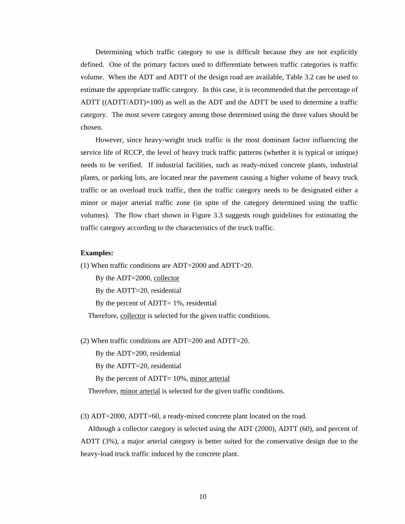
Determining which traffic category to use is difficult because they are not explicitly
defined. One of the primary factors used to differentiate between traffic categories is traffic
volume. When the ADT and ADTT of the design road are available, Table 3.2 can be used to
estimate the appropriate traffic category. In this case, it is recommended that the percentage of
ADTT ((ADTT/ADT)×100) as well as the ADT and the ADTT be used to determine a traffic
category. The most severe category among those determined using the three values should be
chosen.
However, since heavy-weight truck traffic is the most dominant factor influencing the
service life of RCCP, the level of heavy truck traffic patterns (whether it is typical or unique)
needs to be verified. If industrial facilities, such as ready-mixed concrete plants, industrial
plants, or parking lots, are located near the pavement causing a higher volume of heavy truck
traffic or an overload truck traffic, then the traffic category needs to be designated either a
minor or major arterial traffic zone (in spite of the category determined using the traffic
volumes). The flow chart shown in Figure 3.3 suggests rough guidelines for estimating the
traffic category according to the characteristics of the truck traffic.
Examples:
(1) When traffic conditions are ADT=2000 and ADTT=20.
By the ADT=2000, collector
By the ADTT=20, residential
By the percent of ADTT= 1%, residential
Therefore, collector is selected for the given traffic conditions.
(2) When traffic conditions are ADT=200 and ADTT=20.
By the ADT=200, residential
By the ADTT=20, residential
By the percent of ADTT= 10%, minor arterial
Therefore, minor arterial is selected for the given traffic conditions.
(3) ADT=2000, ADTT=60, a ready-mixed concrete plant located on the road.
Although a collector category is selected using the ADT (2000), ADTT (60), and percent of
ADTT (3%), a major arterial category is better suited for the conservative design due to the
heavy-load truck traffic induced by the concrete plant.
10

Less than 50 trucks per a day?
Collector Resident ialMinor arterialMajor arterial
no
yes
yes
no
no
no
yes
yes
Trucks = trucks with 6 or more tires.‐Heavy trucks: semi’s, concrete mixer, dump truck, fire truck, city transit bus
no
More than 10 % of t rucks
in total t raffic?
yes
yes
Frequent heavy t ruck traffic?
yes
Possible Maximum loads for single axle>26 kips
tandem axle>44 kips
Possible Maximum loads for single axle>30 kips
tandem axle>52 kips
heavy truck traffic with near or above maximum
legal loads?
Industrial area or parking lots inducing
heavy truck t raffic?
Figure 3.3 Flow chart for determination of traffic category
11

3.5 Base Conditions (Subgrade Reaction)
Since concrete pavements distribute wheel loads over the ground (subbase and subgrade), the
base supporting conditions influence the deformation and stress distribution of the RCCP.
Therefore, these conditions need to be considered as a design parameter. In concrete pavement
design, subgrade support is characterized by the modulus of subgrade reaction (k). This modulus
of subgrade reaction can be determined through a plate load test, back-calculation of deflection
data, or correlation to other readily determined soil strength parameters.
The modulus of subgrade reaction (k) can be estimated from the California Bearing Ratio
(CBR), as shown in Figure 3.4, or it can be estimated for a given type of soil using Table 3.3. It
can also be estimated for a given subgrade/subbase system using Table 3.4, which was calculated
using the StreetPave software. When detailed information for the subbase and subgrade is
unknown, the following k values may be used for a rough estimate:
Subgrade only : k=100 psi/in
Subgrade with granular subbase : k=150 psi/in
Subgrade with cement treated subbase : k=300 psi/in
3 4 5 6 7 8 9 10 15 20 25 30 40 50 60 70 80 90100
100 150 200 250 300 400 500 600 700Modulus of Subgrade Reaction – k (psi per in.)
California Bering Ratio - CBR Figure 3.4 Approximate interrelationships of bearing values (Middlebrooks and Bertram 1942)
12

Table 3.3 Modulus of subgrade reaction (k) for typical subgrade soils (after StreetPave)
Label Type of Soil Support k (psi/in) CBR
Soil A Fine-grained soils in which silt and
clay-size particles predominate Low 75 to 120 2.5 to 3.5
Soil B Sands and sand-gravel mixtures with moderate
amounts of sand and clay Medium 130 to 170 4.5 to 7.5
Soil C Sands and sand-gravel mixtures relatively free of
plastic fines High 180 to 220 8.5 to 12
Table 3.4 Approximate composite k (psi/in.) values according to subgrade and subbase system.
without
subbase
Thickness of unbound granular or
crushed stone subbase (inch)
Thickness of cement treated subbase
(inch)
4 6 9 12 4 6 9 12
Soil A 100 116 131 155 179 170 228 318 413
Soil B 150 165 183 212 241 243 318 435 557
Soil C 200 213 232 264 297 313 403 543 687
3.6 Edge Support Conditions
Maximum stress induced in the pavement by wheel loads in the pavement changes
according to the location of the wheels. When the wheels are placed at pavement edges,
greater stress occurs in the pavement than for loads placed at the pavement interior (PCA
1984). Therefore, the location of the loads relative to the pavement edges needs to be
determined.
As long as vehicle wheels remain at least two feet from the pavement edge, the edge
support condition can be met. The edge support condition can also be satisfied through the use
of concrete curbs and gutters, tied concrete shoulders, or widened lanes (which consist of
pavement markings that are placed a minimum of two feet from the pavement edge). In
commercial and industrial parking areas, pavements are usually designed with the edge
support condition because vehicle loads are placed mostly on interior slabs. Typically, the
thickness of the supported-edge pavements is 1-2 inches less than that of the unsupported-edge
pavements.
13

More than 2 ft
Figure 3.5 Supported edge condition
Wheels are placed more than 2ft away from edge?
Presence of parking lanes?
Widened lanes? (2 ft . no parking)
Unsupported edge Supported edge
yes
yes
yes
no
no
no
Figure 3.6 Flow chart to determine edge support conditions
14

3.7 Design Tables
Using the four parameters determined in the previous sections: the traffic volume
(ADTT), traffic category, subgrade reaction (k), and edge supporting condition, the required
thickness of RCCP can be determined from design tables (Tables 3.6-3.8) or charts (Figures
3.7-3.9) that have been prepared using the StreetPave software. It should be noted that the
thickness shown in the tables and charts is a finished (compacted) thickness.
In this analysis, pavements were assumed to have two lanes. Design lane distribution,
which refers to the percent of vehicles in one direction that use one lane of the roadway the
most, was assumed to be 100%. Directional distribution, which accounts for the distribution
of loads by direction, was assumed to be 50%. Traffic growth was assumed be 2% per a year.
Table 3.5 shows all of the assumed design parameters. The design charts were made by
interpolating the values in the design tables.
Table 3.5 Design parameters
Reliability
• Specified reliability : 85%
• Allowable percent cracked slabs at the end of design life :
15% for residential and collector areas
10% for minor and major arterial areas
Traffic
• Total number of lanes : 2
• Direction distribution : 50%
• Design lane distribution : 100%
• Truck traffic growth : 2% per year
RCC properties • Flexural strength (modulus of rupture, frup): 650 psi
• Modulus of elasticity (E): 4378 ksi
Design feature
• No dowel bars
• Assumed stress transfer is the same as normal concrete
pavement
It should be noted that no enhanced properties of the RCC were assumed in the design
process. Since the load transfer of the RCCP is known to be better than portland cement
concrete pavement, the thickness can be reduced if this enhanced load transfer is considered.
15

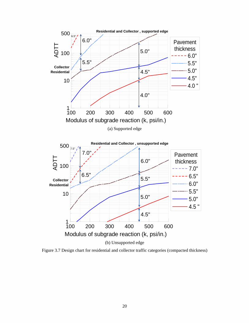
Table 3.6 and Figure 3.7 show the designed compacted pavement thickness for residential
and collector traffic areas. These thicknesses are based on an 85% reliability and a 15 %
cracked slab allowance, and can be applied to parking lots, city streets, and local roads.
For arterial traffic, Table 3.7 and Figure 3.8 and 3.9 provide the designed compaction
thickness based on an 85% reliability and a 10% cracked slabs allowance. These can be
applied to industrial sites, heavy truck parking areas, and primary truck and bus routes.
If traffic follows typical patterns so that the category can be determined using just the
ADTT instead of having to consider heavy truck traffic patterns, Table 3.8, which is a
simplified version of Tables 3.6 and 3.7, can be used to determine the RCCP thickness.
3.8 Design of Composite Concrete Pavement System (RCCP with Asphalt Overlay)
When an asphalt overlay is applied to the RCC, the load bearing capacity of the pavement
will increase. However, since asphalt is a more flexible material than concrete, the load
bearing contribution of the asphalt layer may not be significant. Dellate (2004) reports that the
effect of a thin HMA surface layer on RCC flexural stress is only 1%. Therefore, even though
the design tables and charts presented here have been made for concrete pavements, they can
also be used conservatively for composite pavements ignoring the contribution of the HMA
layer. The PCA (2009) has details of equivalent thicknesses of concrete pavement and
concrete pavements with an HMA overlay, so a more detailed design could be produced
potentially lessening the thickness of the concrete pavement when an HMA overlay is applied
should the owner want to pursue this design methodology, but as detailed above, this manual
provides a more conservative design approach.
3.9 Design Examples
(1) Given conditions:
- Traffic category: residential area
- ADTT: 15
- Subgrade reaction: 150 psi/in.
- Supported edge: yes
From Table 3.6 or Figure 3.7(a), the design thickness of the RCCP should be 5.0 inches.
16

(2) Given conditions:
- ADT: 600, ADTT: 120
- Subgrade reaction: 300 psi/in.
- Supported edge: no
The traffic category is ‘major arterial’ according to Table 3.2 because the ratio of ADTT
is 20%. Whether the exact thickness for the RCCP should be 7.5 or 8.0 inches is not easily
determined using Table 3.7. In this case, Figure 3.9(b) can help identify the more appropriate
thickness for an ADTT of 120. The design thickness should be is 8.0 inches.
(3) Given conditions:
- ADTT: 40
- Subgrade reaction: 300 psi/in.
- Ready-mixed concrete plant located adjacent to the road way.
- Supported edge: yes
A major arterial traffic category is chosen because of the ready-mixed concrete plant
adjacent to the roadway. Using Figure 3.9 (a), 6.0 inches of RCC thickness can be designed
for 40 of ADTT and 300 of subgrade reaction. This example uses the same design conditions
for the Benton County project, which will be presented in Chapter 5.
17

Table 3.6 RCCP thickness design table for residential and collector areas (compacted thickness)
Edge
support Traffic ADTT
Composite modulus of subgrade reaction (k, psi/in)
100 150 200 250 300 500 700
Yes
Residential
3 5.0 4.5 4.5 4.5 4.0 4.0 4.0
10 5.0 5.0 4.5 4.5 4.5 4.0 4.0
20 5.5 5.0 5.0 5.0 4.5 4.5 4.0
Collector
25 6.0 5.5 5.5 5.0 5.0 4.5 4.5
50 6.0 5.5 5.5 5.5 5.0 5.0 4.5
100 6.0 6.0 5.5 5.5 5.5 5.0 4.5
500 6.5 6.0 6.0 6.0 5.5 5.5 5.0
No
Residential
3 6.0 5.5 5.5 5.0 5.0 4.5 4.5
10 6.0 6.0 5.5 5.5 5.5 5.0 4.5
20 6.5 6.0 6.0 5.5 5.5 5.0 5.0
Collector
25 6.5 6.5 6.0 6.0 6.0 5.5 5.0
50 7.0 6.5 6.5 6.0 6.0 5.5 5.5
100 7.0 7.0 6.5 6.5 6.0 6.0 5.5
500 7.5 7.0 7.0 7.0 6.5 6.0 6.0
18

Table 3.7 RCCP thickness design table for minor and major arterial areas (compacted thickness)
Edge
support Traffic ADTT
Composite modulus of subgrade reaction (k, psi/in)
100 150 200 250 300 500 700
Yes
Minor
arterial
50 7.0 6.5 6.0 6.0 6.0 5.5 5.5
100 7.0 7.0 6.5 6.5 6.0 5.5 5.5
500 7.5 7.0 7.0 6.5 6.5 6.0 6.0
1000 7.5 7.5 7.0 7.0 6.5 6.5 6.0
Major
arterial
50 7.0 7.0 6.5 6.5 6.5 6.0 5.5
100 7.5 7.0 7.0 6.5 6.5 6.0 6.0
500 8.0 7.5 7.5 7.0 7.0 6.5 6.0
1000 8.0 8.0 7.5 7.5 7.0 6.5 6.5
No
Minor
arterial
50 8.0 7.5 7.5 7.0 7.0 6.5 6.0
100 8.0 8.0 7.5 7.5 7.0 6.5 6.5
500 8.5 8.0 8.0 7.5 7.5 7.0 7.0
1000 9.0 8.5 8.0 8.0 7.5 7.5 7.0
Major
arterial
50 8.5 8.0 7.5 7.5 7.5 7.0 6.5
100 8.5 8.0 8.0 7.5 7.5 7.0 6.5
500 9.0 9.0 8.5 8.0 8.0 7.5 7.0
1000 9.5 9.0 8.5 8.5 8.0 7.5 7.5
19
100 200 300 400 500 600Modulus of subgrade reaction (k, psi/in.)
1
10
100ADTT
Pavementthickness
6.0"5.5"5.0"4.5"4.0 "
500
4.0"
4.5"
5.0"
5.5"
6.0"6.5"
Residential and Collector , supported edge
CollectorResidential
(a) Supported edge
100 200 300 400 500 600Modulus of subgrade reaction (k, psi/in.)
1
10
100ADTT
Pavementthickness
7.0"6.5"6.0"5.5"5.0"4.5 "
500
4.5"
6.5"
5.0"
5.5"
6.0"
7.5"
Residential and Collector , unsupported edge
CollectorResidential
7.0"
(b) Unsupported edge
Figure 3.7 Design chart for residential and collector traffic categories (compacted thickness)
20

100 200 300 400 500 600Modulus of subgrade reaction (k, psi/in.)
10
100
1000
ADTT
Pavementthickness
7.0"6.5"6.0"5.5 "
5.5"
6.0"
6.5"
7.5"7.0"
Minor arterial , supported edge
(a) Supported edge
100 200 300 400 500 600Modulus of subgrade reaction (k, psi/in.)
10
100
1000
ADTT
Pavementthickness
8.5"8.0"7.5"7.0"6.5"6.0 "
6.0"
6.5"7.5"
8.0" 7.0"
8.5"
Minor arterial , unsupported edge
(b) Unsupported edge
Figure 3.8 Design chart for minor arterial traffic category (compacted thickness)
21

100 200 300 400 500 600Modulus of subgrade reaction (k, psi/in.)
10
100
1000
ADTT
Pavementthickness
7.5"7.0"6.5"6.0"5.5 "
5.5"
6.0"7.0"
7.5"
8.0"
6.5"
Major arterial , supported edge
(a) Supported edge
100 200 300 400 500 600Modulus of subgrade reaction (k, psi/in.)
10
100
1000
ADTT
Pavementthickness
9.0"8.5"8.0"7.5"7.0"6.5 "
6.5"
7.0"8.0"
8.5"
9.5"
7.5"
Major arterial , unsupported edge
9.0"
(b) Unsupported edge
Figure 3.9 Design chart for major arterial traffic category (compacted thickness)
22
4. Construction Guidelines for RCC pavement2
4.1 Selection of Paving Material
4.1.1 RCCP Compared to Asphalt Pavement
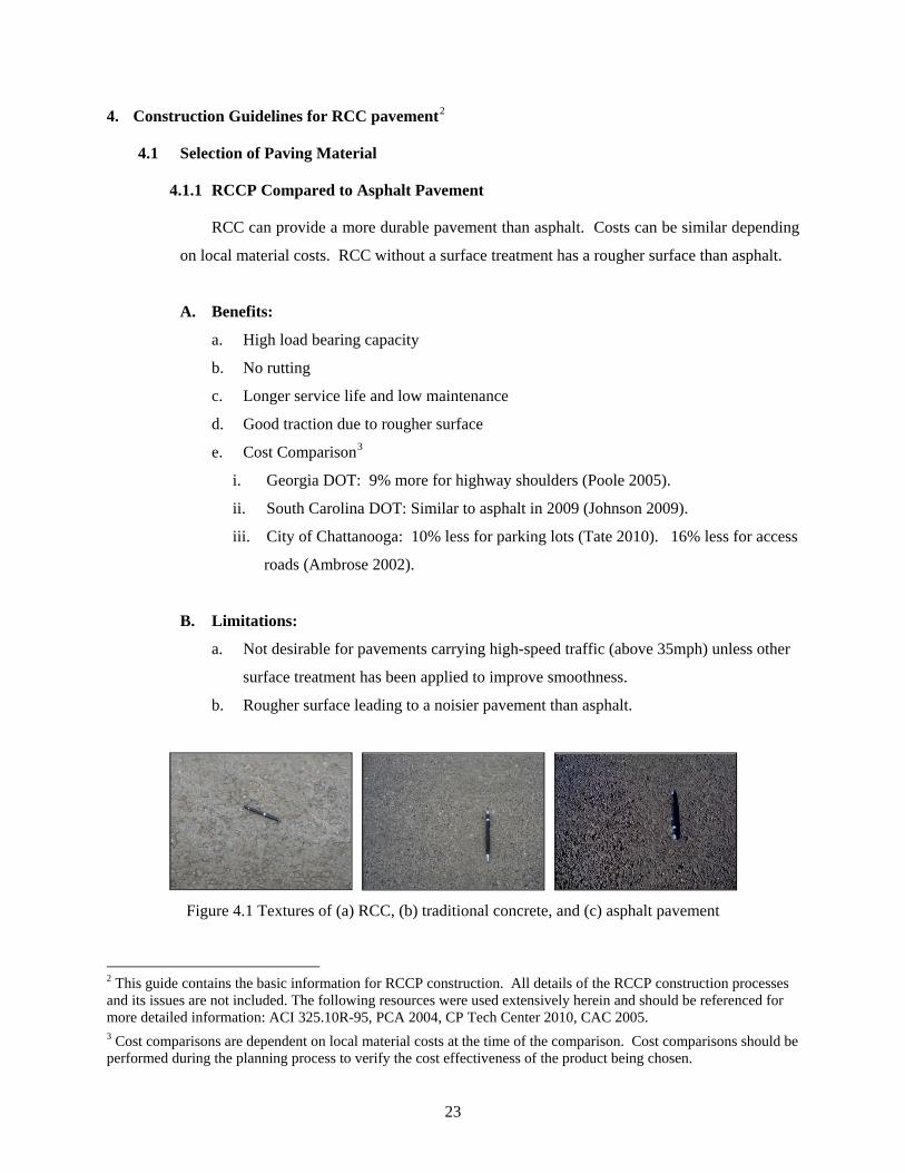
RCC can provide a more durable pavement than asphalt. Costs can be similar depending
on local material costs. RCC without a surface treatment has a rougher surface than asphalt.
A. Benefits:
a. High load bearing capacity
b. No rutting
c. Longer service life and low maintenance
d. Good traction due to rougher surface
e. Cost Comparison3
i. Georgia DOT: 9% more for highway shoulders (Poole 2005).
ii. South Carolina DOT: Similar to asphalt in 2009 (Johnson 2009).
iii. City of Chattanooga: 10% less for parking lots (Tate 2010). 16% less for access
roads (Ambrose 2002).
B. Limitations:
a. Not desirable for pavements carrying high-speed traffic (above 35mph) unless other
surface treatment has been applied to improve smoothness.
b. Rougher surface leading to a noisier pavement than asphalt.
Figure 4.1 Textures of (a) RCC, (b) traditional concrete, and (c) asphalt pavement
2 This guide contains the basic information for RCCP construction. All details of the RCCP construction processes and its issues are not included. The following resources were used extensively herein and should be referenced for more detailed information: ACI 325.10R-95, PCA 2004, CP Tech Center 2010, CAC 2005. 3 Cost comparisons are dependent on local material costs at the time of the comparison. Cost comparisons should be performed during the planning process to verify the cost effectiveness of the product being chosen.
23

4.1.2 RCCP Compared to Concrete Pavement
A. Benefits:
a. Similar load bearing capacity and durability with traditional concrete pavement.
b. Simple construction process without reinforcements and dowels.
c. Prompt re-commencement of traffic.
i. Typically after 5 hours of placement for light-weight vehicles
ii. Typically after 24 hours of placement for heavy-weight vehicles.
d. Costs Comparison4
i. Similar to or lower than traditional concrete pavement.
ii. 25-50 % less than conventional concrete pavement (US Amy Corp of Engineers,
2000).
B. Limitations:
a. Not desirable for pavements carrying high-speed traffic (above 35mph) unless other
surface treatment has been applied to improve smoothness.
b. Rougher surface than traditional concrete pavements.
4.1.3 Benefit of RCC with an Asphalt Surface Treatment
RCC can be used as base material for asphalt pavement instead of aggregate base.
A. Benefits:
a. Higher load bearing capacity than asphalt pavement.
b. Reduced size and depth of ruts in the asphalt layer.
c. Longer service life and lower maintenance than asphalt pavement.
d. Cost Comparison4
i. City of Columbus: Initial costs are similar to asphalt pavements for city streets
(PCA 2010).
ii. For lower volume roads, $1.40/sq yd - $2.70/sq yd cost reduction than asphalt
pavement (Lee and McCullouch 2006).
4 Cost comparisons are dependent on local material costs at the time of the comparison. Cost comparisons should be performed during the planning process to verify the cost effectiveness of the product being chosen.
24

4.2 Construction Plan
4.2.1 Requirements
The construction sequences from production to compaction must be coordinated so that a
continuous operation occurs with no delays in any of the construction phases. Mixing,
transporting, placing, and compacting must be carefully timed and planned.
A. Minimal Interruptions
RCC must be paved continuously with minimal interruptions
a. The paving and supply rates should be the same
b. Fresh and cold construction joints must be planned before the start of construction
B. Timed Construction
The RCC construction processes must be timed.
a. RCC must be compacted within a maximum of 60 minutes from the initial water-
cement contact.
b. Fresh joints must be compacted within a maximum of 60 minutes from initial water-
cement contact. Although this time period could extend as long as 90 minutes (ACI
2001, PCA 2004), this document details a conservative approach in an effort to
achieve the best performance from the material. The Engineer can use his judgment
based on the other resources referenced, weather conditions, use of retarding
admixtures, other pertinent factors and experience to determine what time period
would work best within the plan for the specific project.
C. Variation of the Compaction Time
a. The time to compaction can increase, when set retarding admixtures are used.
b. The time to compaction can decrease, when:
i. The ambient temperature is high
ii. The ambient humidity is low
iii. The wind is high
c. RCC construction in hot weather (CP Tech Center 2010)
i. Typically, compaction should be completed within 15 minutes of spreading and
45 minutes of initial mixing.
ii. Strength may decrease when RCC is mixed above 70oF and compacted after more
than 30-45 minutes.
25

4.2.2 Construction Plan: An Example of a 2-Lane Paving Project
Detailed procedures to estimate the paving plan are explained in Appendix C.
A. Production Resources
a. RCC production facilities
- Batch plant
Production rate (Qp): 50 cys/hr
- Transit mixers
Number of transit mixers (Ntm): 4
Capacity of mixers (qtm): 5 cys
Transport time from the batch plant to the site (ttm): 10 minutes
Mix time (tmix): 5 minutes
Discharge time (tdis): 5 minutes
Water contacts the cement at the plant
Compaction time limit from water-cement contact (tcritical): 60 minutes.
b. Equipment available
- Dump trucks
Number of dump trucks (Ndt): 2
Capacity of dump trucks (qdt): 5 cys
Duration from the loading to the discharging (tdt): 7 minutes
- Number of pavers (Npav): 1
c. Pavement geometry
Width (w): 10 feet
Thickness (t): 6 inches
Length: 200 feet
26

B. Construction Plan
Figure 4.2 demonstrates the production and delivery processes of transit-mixed
RCC. The supply rate, which will be used for determining the paver speed, and the
delivery time, which will be used for estimating the paving time needed for the RCC
mixture to be placed and compacted, can be estimated using this figure.
Batch Transport Mix
Batch and transit mixer
ProductionRate : Qp
Transfer Discharge
Plant Dump truckTransit mixer
ttm tdttmix
Time
Paver
MixtureVolume Ntm*qtm Ndt*qdt
Qtm=Ntm*qtm / (2*ttm+tmix+tdis) Qt= Ndt*qdt / (2*tdt)Mix rate Transfer rate
Discharge
tdis
Delivery time
Rate
Qtm : mix ratettm : transport time of a transit mixertmix : mix time tdis : discharge timeNtm : number of transit mixersqtm : capacity of one transit mixer
Qtm : transfer ratetdt : transfer time of a dump truckNdt : number of dump trucksqdt : capacity of one dump truck
Figure 4.2 Supply rate and delivery time for dry batched RCC
a. Supply rate
The critical supply rate (Qsup) for the RCC mixture is the slowest rate involved in the
RCC production, mix, and transfer processes.
i. Production rate:
Qp = 50 cubic yards (cys)/ 1 hr (60 minutes) = 0.833 cys/ 1 min
ii. Mixing rate:
Qm = Ntm*qtm / (2*ttm+tmix+tdis)
= 4 transit mixers *5 cys / (2*10 min+5 min+5 min) = 0.667cys/1 min
27

iii. Transfer rate:
Qt = Ndt*qdt / (2*tdt)
= 2 trucks * 5 cys / ( 2*7 min) = 0.714 cys/ 1 min
Therefore, the critical supply rate is:
Qsup = 0.667 cys/ min
b. Delivery time
The delivery time (td) is the duration from the initial water-cement contact to the
moment of discharge into the paver.
td = ttm + tmix + tdis + tdt = 10+ 5 + 5 + 7=22 minutes
c. Estimated paver speed
In order to minimize the starts and stops of the paver, which can cause potential
problems in the construction process, the paving rate (Qpav) needs to be balanced with the
RCC supplying rate. One effective method for matching the paving rate with the RCC
production is to adjust the paver speed with respect to the RCC supply rate. Assuming
that the paving rate is equal to the supply rate results in the following:
v QN
= (0.667 cys/min) / (1*10 ft * 6 in)
= (0.667 cys/min)*(27 cu ft/1 cys) / (1*10 ft * 0.5 ft)
= 3.6 ft/min
The paving can be planned using this estimated paver speed as long as the speed is in
a reasonable range. It is reported that there is no significant difference in lay-down
density at speeds ranging from 7 to 12 feet per minute (Nanni et al 1996).
d. Estimated paving time
Fresh RCC mixture must be compacted within a specific time period (tcr) in order to
create fresh joints in the pavement. This critical time is typically 60 minutes after mixing.
Therefore, the estimated time for RCC to be placed and compacted can be calculated as
follows: tpav = tcritical – td = 60 min – 22 min = 38 min
28

e. Maximum length of 1 application
The application length (Lappl) that a paver can complete during this estimated paving
time is calculated by:
Lappl = vpav*tpav = 3.6 ft/min *38 min = 137 ft
f. Paving plan
Since the maximum length of 1 application is 137 feet, the pavement can be
constructed without a cold joint when the length of one segment does not exceed 137 feet.
Therefore, when the length of each segment is set at 100 feet as shown in Figure 4.3(a),
there is no cold joint required.
Length of 1 segment:
Lseg= 100ft
Actual paving time for 1 segment:
tseg= Lseg/vpav = (100 ft) / (3.6 ft/min) = 28 min
If the whole length (200 feet) of the pavement is paved at once, as shown in Figure 4.3(b),
the joint between the adjacent lanes will be a cold joint.
Figure 4.3 Example construction plan for a 200-foot, 2-lane paving project using 1 paver
29
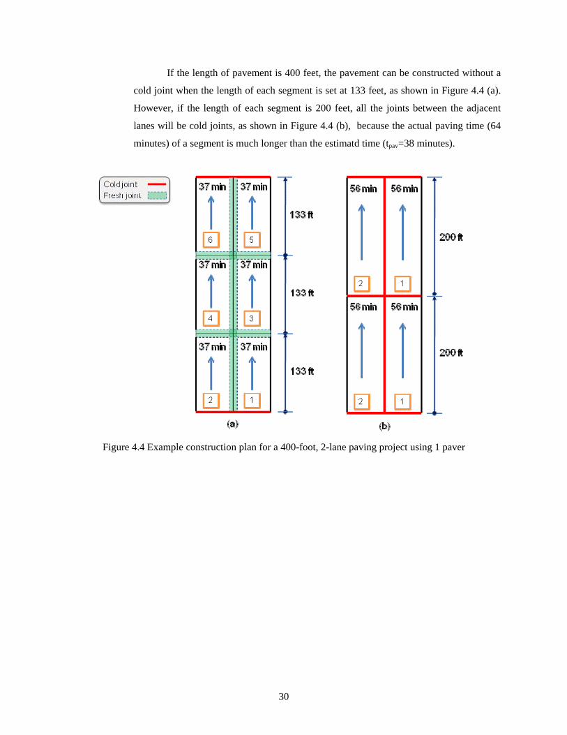
If the length of pavement is 400 feet, the pavement can be constructed without a
cold joint when the length of each segment is set at 133 feet, as shown in Figure 4.4 (a).
However, if the length of each segment is 200 feet, all the joints between the adjacent
lanes will be cold joints, as shown in Figure 4.4 (b), because the actual paving time (64
minutes) of a segment is much longer than the estimatd time (tpav=38 minutes).
Figure 4.4 Example construction plan for a 400-foot, 2-lane paving project using 1 paver
30

4.3 Subgrade/Subbase Preparation
4.3.1 Proper Compaction
The requirements for an RCCP base are the same as those for conventional
concrete pavement. The base course must provide sufficient support to allow the full
compaction of the RCC throughout the entire thickness of the pavement.
A. Necessary Requirements
a. The density of the base must be stiff enough (above 95% of modified Proctor) to
support the RCCP.
B. Recommended Procedures
a. Proof rolling can be used to verify the surface compaction.
C. Potential Negative Consequences
a. Improper support conditions will cause an irregular wavy surface.
b. Improper support conditions will cause uneven stress distribution, and resulting in a
decreased service life for the pavement.
D. For More Information,
a. RCCP Specification 3.03: Preparation of Subgrade/Subbase
b. INDOT Standard Specification Sections 207, 302
i. Note: The drainage layer detailed in the Subbase Specification of the INDOT
Standard Specifications is not recommended for RCCP.
c. ACI 325.10R: 7.2 Subgrade and Base Course Preparation
Figure 4.5 Subgrade treatment process
31

4.3.2 Moisture Condition of Subgrade
RCC is sensitive to the moisture content of the subgrade and subbase. To avoid drawing
moisture from the RCC, the subgrade and subbase should be kept at the proper moisture
content during the paving process.
A. Necessary Requirements
a. The base must be kept uniformly moist at the time of RCC placement without
ponding water.
b. The base must be kept clean and free of foreign material.
B. Recommended Procedures
a. If the surface is dry, moisten the surface without creating mud or ponded water.
b. Areas with excessive moisture should be removed and replaced with new material
meeting the specified requirements, or the paving operations delayed until the proper
conditions are met.
c. If the area is saturated, a drainage system may be necessary.
C. Potential Negative Consequences
a. Subbase or subgrade that is below the recommended moisture content will draw
moisture from the RCCP causing improper compaction of the RCCP: See Section
4.4.1.
b. Subbase or subgrade that is above the recommended moisture content will cause
swelling of the RCCP and unexpected deformation during compaction: See Section
4.4.1.
D. For More Information
a. RCCP Specification 3.03: Preparation of Subgrade/Subbase
b. INDOT Standard Specification Sections 207, 302
i. Note: The drainage layer detailed in the Subbase Specification of the INDOT
Standard Specifications is not recommended for RCCP.
c. ACI 325.10R: 7.2 Subgrade and Base Course Preparation
32

4.4 Moisture Contents of the RCC Mixture
Proper moisture content is critical to adequate compaction and long-term performance.
Successfully proportioned and mixed RCC looks and feels like damp gravel.
A. Necessary Requirements
a. The moisture of the RCC mixture must be near the optimal moisture content when it
is placed and compacted. The acceptable moisture content can vary within a narrow
range, as shown in Figure 4.6, which shows the typical moisture-density curve.
160
155
150
1452.0 3.0 4.0 5.0 6.0 7.0
Wet
den
sity
(pcf
)
Moisture content (%)
100%
98%
4.8 %3.8 %
Targeted moisture content3.8 ~ 5.8 %
Figure 4.6 Typical relationship between density and water content of RCC mixture
b. The moisture content of aggregate should be measured and the mixtures updated
regularly during construction. The amount of water in the aggregate can significantly
affect the mixture. Mixtures may not require any additional water if the necessary
amount is present in the aggregates at the time of mixing.
B. Recommended Procedures
a. Keep the moisture content slightly above rather than below optimum during the
production process to compensate for water loss prior to placement and compaction.
b. Verify the moisture content of aggregates before production.
c. Verify the moisture content of the RCC mixture before the compaction at the job site.
33

C. Potential Negative Consequences
a. Improper RCC moisture content can cause significant problems affecting the
development of mechanical properties, placement operations, and the quality and
durability of the pavement structure.
b. Targeted density cannot be achieved when the moisture content is out of the desired
range (See Figure 4.6).
c. Excessive moisture (wetter mixture) can cause:
i. Insufficient compaction.
ii. ‘Pumping’ behavior during compaction.
iii. Excessive deformation during compaction resulting in irregular surfaces.
iv. Adhesion to the steel drums of the rollers, which can decrease the surface quality.
d. Insufficient moisture (drier mixture) can cause:
i. An increase in segregation during the construction processes.
ii. Difficulty in placement; rise of paver on the mixture, formation of bumps or
depressions.
iii. Surface tearing and raveling, which results in rough surfaces.
iv. Insufficient compaction.
v. Coarser (open) finished surfaces.
D. For More Information
a. Production of Roller Compacted Concrete (PCA 2006)
b. Guide for Roller Compacted Concrete Pavement (CP Tech Center 2010)
Figure 4.7 Improper moisture content:
(a) Deformation of the pavement due to excessive moisture
(b) Tearing of RCC surface due to insufficient moisture content
34

4.5 Transportation
RCC mixture is typically transported in dump trucks or transit mixers. The transfer of the
material to the dump trucks prior to placement in the paver can be made at the plant or the job
site. If a central mix plant is used, the dump trucks can be loaded directly from the plant. Use
of dump trucks for extended hauling distances should be planned carefully and the appropriate
precautions taken to avoid moisture loss of the RCC mixture in order to maintain the optimal
conditions of the RCC mixture.
4.5.1 Transportation/Transfer of RCC Mixture
A. Necessary Requirements
a. The RCC mixture must be protected from excessive evaporation.
b. The RCC mixture must be prevented from segregating.
B. Recommended Procedures
a. Protect the RCC mixture with proper cover.
b. Minimize free fall distance when the RCC mixture is discharged.
C. Potential Negative Consequences
a. The loss of moisture causes problems in all subsequent processes and also reduces
the performance of the RCCP (See Section 4.4.1).
b. Excessive segregation decreases the strength reducing the long term durability and
service life.
D. For More Information
a. RCCP Specification 3.05: RCC Transportation.
b. Production of Roller Compacted Concrete (PCA 2006)
c. ACI 325.10R: 7.3 Batching, Mixing, and Transporting.
Figure 4.8 RCC is discharged from transit mixers into dump trucks
(a) directly, (b) by conveyers, or (c) by loaders
35

4.5.2 Cleaning of Truck
A. Necessary Requirements
a. Dump trucks must be kept clean by frequent washing.
b. All build up and/or remaining RCC mixture must be removed from the truck.
B. Recommended Procedures
a. Clean the truck bed after each delivery.
b. Wash truck and truck bed frequently
C. Potential Negative Consequences
a. Older and dried RCC sediment causes problems during subsequent paving processes
(See Section 4.4.1).
D. For More Information
a. RCCP Specification 3.05: RCC Transportation.
b. Production of Roller Compacted Concrete (PCA 2006)
c. ACI 325.10R: 7.3 Batching, mixing, and transporting.
Figure 4.9 RCC sediment in a truck bed (circled)
36

4.6 Placement
RCC is typically placed with an asphalt paver. During paving, segregation must be
minimized. A uniform surface and thickness of the RCCP needs to be achieved.
A. Necessary Requirements
a. The paver must maintain a constant speed minimizing starts and stops.
b. The surface and thickness of the placed RCC must be uniform without excessive
tears or ridges.
B. Recommended Procedures
a. Never completely empty the paver hopper.
b. Do not raise the sides of the hopper since larger aggregates tend to accumulated on
the hopper sides.
c. Correct any segregation with fresh RCC mixture before compaction.
C. Potential Negative Consequences
a. Frequent stops will cause the formation of bumps or depressions on the final surface.
D. For More Information
a. RCC Specification: 3.06 Placing RCC
b. RCC Specification: 3.13 Quality Control
c. ACI 325.10R: 7.4 Placing
d. ACI 309.5R
Figure 4.10 Segregation of RCC mixtures
37

4.7 Construction Joints
Since joints are critical to adequate smoothness and density, fresh and cold joints must be
planned carefully and treated individually. Fresh joints usually need to be placed and
compacted within 60 minutes of RCC mixing of the previous lane. See Section 4.2.1 for
additional details.
A. Necessary Requirements
a. A vertical joint can be considered a fresh joint when an adjacent RCC lane is placed
and compacted within 60 minutes of RCC mixing of the previous lane.
b. Any planned or unplanned joints that do not qualify as fresh joints must be
considered cold joints.
c. Compaction near cold joints needs to be conducted according to Section 4.8.2.
B. Recommended Procedures
a. Follow the paving plan.
b. Limit the length of the paving lanes.
c. Apply evaporation retarder to the fresh joints, if necessary.
C. Potential Negative Consequences
If a fresh joint is compacted too late:
a. It will cause improper bonding between two lanes.
b. It will cause cracks at the interface between old and new placements.
D. For More Information
a. RCC Specification: 3.06 Placing RCC
b. ACI 325.10R: 7.6 Joint Construction
c. ACI 309.5R
Figure 4.11 Longitudinal cracks due to late compaction of the fresh longitudinal joint
38

4.8 Compaction
RCC is compacted with rollers like asphaltic concrete; although, the rolling requirements
are different. Normally, one or two static passes with a steel-wheel roller are used for the
pavement breakdown, followed by several passes with a vibratory roller.
4.8.1 General
A. Necessary Requirements
a. The RCC mixture must be compacted while it is fresh.
b. The compaction operation must begin within 10 minutes of placement.
c. The required density of the RCCP must be achieved.
d. Repairs cannot be made after compaction.
B. Recommended Procedures
a. Closely follow the paving plan, specifications, and recommendations:
i. During the course of vibratory compaction, do not stop the roller on the pavement
in the vibratory mode.
ii. Caution should be exercised while rolling edges and end strips with the roller in
vibratory mode. Excessive vibration can lead to edge deformation and collapse.
iii. Changes in direction of tandem rollers should not be performed near previously
compacted fresh RCCP.
C. Potential Negative Consequences
a. Insufficient compaction will cause a decrease in strength and durability.
b. Excessive rolling will decrease the density of the upper portion of the pavement.
D. For More Information
a. RCC Specifications: 3.08 Compacting
b. RCC Specifications: 3.09 Joints
c. ACI 325.10R: 7.5 Compaction
d. ACI 309.5R
39

4.8.2 Joint Compaction
A. Edge Compaction
Compaction should begin at one of the edges (usually the outside first). When
the edge is a fresh joint, the outer 1-1.5 feet of the paving lane are left uncompacted as
shown in Figure 4.12 (a). However, when the edge is a cold joint, the lane is compacted
over its full width without leaving an uncompacted edge, as shown in Figure 4.12 (b).
For the longitudinal direction, the same methods are applied. When the edge is a
fresh transverse joint, the outer 1-1.5 feet of the paving lane are left uncompated as seen
in Figure 4.12 (c), and when the edge is a cold transverse joints, the lane is compacted
over its full length as shown in Figure 4.12 (d).
longitudinal fresh joint
Fresh RCCP
Leave 1-1.5 ft uncompacted
Fresh RCCP
(a) (b) longitudinal cold joint
Leave 1-1.5 ft uncompacted
Fresh RCCP
transverse fresh joint
Fresh RCCP
transverse cold joint(c) (d)
Figure 4.12 Compaction of (a) longitudinal fresh joint, (b) longitudinal cold joint,
(c) transverse fresh joint, and (d) transverse cold joint.
Figure 4.13 Edge collapse due to improper compaction or insufficient support of the base
40

B. Fresh Joints
Fresh joints are constructed by leaving the outer 1-1.5 feet of the paving lane un-
compacted during the rolling operation. This uncompacted edge is then used to set the
height of the paver screed for paving the adjacent lane. After the adjacent lane is placed,
this fresh joint is integrated by simultaneously compacting the uncompacted edge and
adjacent lane (see Figures 4. 14 and 4.15).
Longitudinal fresh joint
Fresh RCCPOld
Fresh RCCPOld
Longitudinal fresh joint
Transverse fresh joint
Fresh RCCPOld
Fresh RCCPOld
Transverse fresh joint(a) (b)
Figure 4.14 Compaction for (a) fresh longitudinal joint and (b) fresh transverse joint
Figure 4.15 Fresh joint construction (a) Uncompacted edge of the previous placement (b) the fresh joint
compaction between the two adjacent lanes
41

C. Cold Joints
When the first (or previous) RCC placement has hardened so that it cannot be
compacted with the fresh lane, cold joints form. This usually occurs when more than one
hour has passed between the placement of the two adjacent lanes. In order to continue
paving, cold joints need to be trimmed. This trimming is usually done with a concrete
saw. After the successive adjacent lane is paved to the remaining vertical edge, fresh
overlapping RCC material is usually pushed back onto the new lane before the joint is
compacted. Figure 4.16 shows the construction procedures for the cold joints.
(a) longitudinal cold joint (b) transverse cold joint
Figure 4.16 Rolling patterns for cold construction joints
Figure 4.17 Longitudinal cracks due to late compaction of the fresh longitudinal joint
42

D. Examples
Figures 4.18 and 4.19 show examples of the paving and compacting processes
when the joints between the adjacent lanes are fresh joints. It needs to be noted that the
compacting sequences can change depending on the construction conditions. Preferably,
the center strip (fresh joint) would be compacted first.
(1) First lane with fresh joint
(2) second lane with cold joint
Paver
This area should be compacted together
(b) Rolling sequences
roller
(a) Paving sequences
12
Figure 4.18 2-lane pavement with a longitudinal fresh joint: (a) paving sequence and (b) rolling sequence
(1) Second lane with fresh joint
(2) Third lane with cold joint
Figure 4.19 3-lane pavement with longitudinal fresh joints: (a) paving sequence and (b) rolling sequence
Paver
This area should be compacted together
(b) Rolling sequences(a) Paving sequences
3 2 1
43

4.9 Special Consideration for Placement and Compaction
4.9.1 Inaccessible Areas
A. Placement and Compaction
a. Small areas or areas inaccessible to paver shall be placed by hand or other paving
equipment such as graders and dozers. For very small areas a hand tap can be used.
b. Places inaccessible to large vibratory rollers shall be thoroughly compacted with
walk-behind rollers and hand-tampers to the required density.
c. Multiple thin lifts can be used, as necessary.
d. Compaction of these areas must satisfy minimum density requirements of the RCCP.
B. Use of Conventional Pavement
a. An alternate and preferred method for paving inaccessible areas is to use cast-in-
place, air-entrained concrete with a minimum compressive strength of 4000 psi (27
MPa) or as specified by the Engineer.
b. For radii, driveway approaches, and other areas, which are too large for hand work
but difficult for paver, asphalt or conventional concrete is better suited
c. If the taper is less than four inches in thickness, then asphalt or conventional
concrete will be needed.
d. In areas that may be subjected to high load transfer, the cast-in-place concrete needs
to be doweled into the RCC.
Figure 4.20 Placement of inaccessible area
44
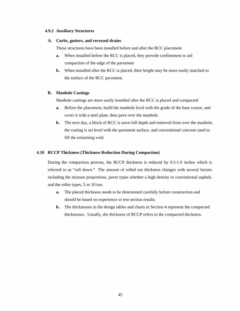
4.9.2 Auxiliary Structures
A. Curbs, gutters, and recessed drains
These structures have been installed before and after the RCC placement
a. When installed before the RCC is placed, they provide confinement to aid
compaction of the edge of the pavement
b. When installed after the RCC is placed, their height may be more easily matched to
the surface of the RCC pavement.
B. Manhole Castings
Manhole castings are more easily installed after the RCC is placed and compacted
a. Before the placement, build the manhole level with the grade of the base course, and
cover it with a steel plate, then pave over the manhole.
b. The next day, a block of RCC is sawn full depth and removed from over the manhole,
the casting is set level with the pavement surface, and conventional concrete used to
fill the remaining void.
4.10 RCCP Thickness (Thickness Reduction During Compaction)
During the compaction process, the RCCP thickness is reduced by 0.5-1.0 inches which is
referred to as “roll down.” The amount of rolled out thickness changes with several factors
including the mixture proportions, paver types whether a high density or conventional asphalt,
and the roller types, 5 or 10 ton.
a. The placed thickness needs to be determined carefully before construction and
should be based on experience or test section results.
b. The thicknesses in the design tables and charts in Section 4 represent the compacted
thicknesses. Usually, the thickness of RCCP refers to the compacted thickness.
45

4.11 Curing
Proper curing is necessary to insure the strength and quality of the surface of the
pavement. A high-quality top surface prevents scaling, dusting and raveling of the hardened
surface.
A. Requirements
a. Within 60 minutes after final rolling, RCCP shall be cured with an approved white
pigmented liquid membrane forming compound.
b. When the surface treatment or application will be applied at the same day, curing
liquid membrane shall not be used but the surface shall be kept moist until the
surface treatment is applied.
B. Recommended Procedures
a. Keep all exposed surfaces of the RCCP moist until the final curing.
b. When curing compound is used, apply curing compound according to the
manufacturer’s recommendations.
c. When curing compound is prohibited,
i. Plastic sheet or burlap can be used.
ii. Wetting or evaporation retarder can be used for a short duration protection.
C. Potential Negative Consequences
a. Improper curing will cause surface raveling, which results in a rough surface and a
decrease in service life.
D. For More Information
a. INDOT PCCP specification 302
b. RCCP Specification: 3.12 Curing
c. ACI 325.10R: 7.7 Curing and Protection
Figure 4.21 Curing with white pigmented curing compound Figure 4.22 Raveling of RCC surface
46

4.12 Quality Control
A. Before and during production, verify:
a. The moisture content of the aggregates, especially at the beginning of each day’s
production.
B. At the job site, verify:
a. The moisture content of the mixture, especially for the first batch.
b. The uniformity of the mixture.
c. The moisture content of the placed RCC before compaction.
d. The density of the RCCP after compaction.
C. For More Information
a. RCCP Specification: 4. QC and QA
b. ACI 325-10R: 8. Inspection and Testing
c. ACI 309.5R
Figure 4.23 Sampling during placement
Figure 4.24 Density measurements after final compaction with a nuclear gauge
47

4.13 Nuclear Density Measurement
A. RCC Density Measurement
Two methods are available for measuring the density and moisture contents of RCCP:
a. Direct transmission method
The probe is inserted into a preformed hole in the RCCP. The deepest reading will be the
measurements (USACE 2008). USACE (2008) recommend that the deepest reading
should be approximately 2 inches less than the depth of pavement slab, however the
ASTM C 1040 (2008) defines the maximum is 1 inch.
b. Backscatter method
The probe is located on the surface. Backscatter gauge readings represent the density in
the top 3 to 4 inches of material, and top 2 inches determines 80 to 95% of the measured
count rate (ASTM C 1040).
Because the backscatter method can measure the density and moisture content of
top 3 to 4 inches, and the density of the upper layer tends to be achieved easily than the
bottom layer, the backscatter method may not be suitable for density measurement of
RCCP (ACI 1995).
Therefore, the direct transition method is recommended in the most of the RCC
specifications including this LTAP guide specification. However, the backscatter method
may be used at the discretion of the Engineer for the moisture or density measurements of
the upper layer.
B. For More Information
a. ACI 325-10R: 8. Inspection and Testing
b. ACI 309.5R: 6. Construction Control
c. ASTM C 1040/C 1040M
d. USACE Unified Facilities Guide Specification(UFGS)-32 13 16.16 RCCP
48

4.14 Traffic Management
A. Construction vehicles
a. Construction vehicles or equipment may be allowed on the pavement before opening
to traffic, as approved by the Engineer.
b. Any construction vehicles or equipment that may damage the RCCP will not be
allowed on the RCCP unless adequate protection is provided.
c. Approved joint cutting saws may be operated on the RCCP.
B. Non-construction vehicles
a. RCCP may be opened earlier if the measured compressive strength is 3500 psi (26
MPa) or greater.
b. Alternatively, at the discretion of the Engineer,
i. RCCP may be opened to light-weight traffic (less than 11,000 lbs G.V.W) after 5
hours of placement.
ii. RCCP may be opened to heavy-weight traffic after 24 hours of placement.
C. For More Information
a. RCCP Specification: 3.13 Opening to Traffic
49

5. Local Case Studies of RCC Pavements in Indiana
5.1 General
Several RCCP projects have been constructed in Indiana recently. A few of these
projects are listed below in Table 5.1. Benton, Daviess, St. Joseph, and Union Counties
provided information for the case studies and are described briefly in this manual. It should be
noted that these case studies are an example of actual conditions and not a part of the
recommendations or guidelines of this manual. Opinions expressed in the case studies are
those of the speaker and not representative of the references or this document. RCCP was
chosen primarily due to a high volume of heavy-truck traffic or because of the economy of the
material at the time of the project. A ready-mixed concrete plant and a timber handling
facility are located on the Benton and St. Joseph County projects, respectively. Union County
used RCCP primarily due to its low cost, but its durability was also a deciding factor to
provide resistance to flood damage in a prone area.
Benton, Daviess and Union Counties constructed the RCCP by themselves using RCC
mixture supplied from local ready mix concrete plants. St. Joseph County had their RCCP
placed by a contractor.
Table 5.1 RCCP projects recently completed in Indiana
Locations RCC suppliers
Benton County Ready Mixed Concrete Otterbein
Daviess County Jones and Sons Ready Mix
Henry County Busters Ready Mix
City of Indianapolis Builders Concrete
St. Joseph County Kuert Concrete
Union County IMI ready mix
50

5.2 Benton County
Benton County constructed a RCCP on a local road in 2009. Figure 5.1 shows an aerial
photograph of the project. Although the volume of traffic at the site was not large, there was
frequent heavy-truck traffic from the ready-mixed concrete plant adjacent to the road (S900 E).
Therefore, RCC material was selected for a trial expecting a longer service life of the
pavement. A brief description of the project is available in Table 5.2.
Table 5.2 Benton County project description
Description
Overview A local road near a ready-mix concrete plant
Location South 900 East (from rail road) to 750 South
Owner Benton County, Highway Supervisor, Tom Collins, (765) 884-0420
Designer CRT Concrete Consulting, LLC, Christopher R. Tull, (317) 270-4428
Installation Benton County
RCC supplier Ready-Mixed Concrete, Otterbein, Brent Pursell, (765) 583-2358
Dates of construction 2009
Geometry 6" thick x 22' width x 579' length
Duration of construction 8 hours
Figure 5.1 Aerial photograph
51

The designer used the StreetPave software to determine the required pavement section.
The mixture proportions for the RCC were: 1400 lbs of #8 stone, 600 lbs of #12 stone, 1500
lbs of sand, 450 lbs of cement, 100 lbs of fly ash, and 23 gallons of water.
The RCC was placed with a Caterpillar AP655C paver and compacted with a 10-ton
roller in 2 passes without vibration. The core density measured after the construction was
approximately 154 pcf. Traffic was allowed on the pavement 24 hours after construction.
Ensuring that the RCC mixture is placed with a uniform thickness is essential for
achieving high-quality RCCP. The Benton County agent said that they had difficulties placing
the mixture uniformly due to the excessive stiffness of the mixture. The agent recommended
using a less dense mixture to minimize problems. Another suggestion included to minimize
stopping and starting of the paver. It was felt that the stiff mixture and the starting and
stopping caused the paver to ride up on top of the mixture creating irregularities in the profile
of the surface affecting ride and thickness of the final pavement
(a) Since the transit mixer could not discharge the
mixture into large dump trucks directly, the mixture
was discharged into a loader first, then transferred
into the dump trucks.
Figure 5.2 Benton County RCCP construction
(continued)
52

(b) The mixture in the dump trucks was
discharged into a paver. In this case, all the
loaded mixture should be unloaded, and the truck
bed should be cleaned prior to the next load (See
Section 4.5.2).
(c) The paver placed the RCC mixture. During
this step, the paver should be kept moving to
avoid possible problems (See Section 4.6)
the two adja
joint shoul
RCC
(d) A roller compacted the fresh joint between
cent lanes. In this case, the fresh
d be compacted within an hour of the
mixture mixing of the previous lane.
Figure 5.2 Benton County RCCP construction
53

5.3 Daviess County
Daviess County built two RCCPs in 2009 on a trial basis. Table 5.3 describes the
information for the projects. Jones and Sons Concrete supplied the RCC mixture, and the
County constructed the pavement. Figure 5.3 shows the bid document for the RCC mixture.
The mixture proportions used in the project were: 450 lbs of cement, 100 lbs of pozzolan,
60% stone (# 8 limestone & pea gravel proportioned at 50% each), 40% #23 washed sand, and
5% water (209 lbs). Several admixtures were added to the mixture including a water reducer,
air-entraining and retarding agents. The measured strength from the 2 cores taken were: 1630,
3460, and 4120 psi at 3, 9 and 28 days for CR 450S, and 3950 and 4890 psi at 7 and 28 days
for CR 200E.
The RCC was placed with a Blaw Knox PF-161 paver, and compacted with an Ingersol
Rand DD-9010 roller in 1 vibratory pass and 2 static passes. Curing compound was applied at
the rate of 1 gallon/200 sq ft after the final compaction. Traffic was allowed on the new
pavements after 1 day on 200E and after 3 days on 450S. Figure 5.4 shows the construction
process of this project.
Table 5.3 Daviess County project description
Description
Location CR 200E (from CR 675S north 1761') CR 450S (from CR 300W west 2821')
Owner Daviess County, Highway Supervisor, Larry McLin, (812) 444-5798
Designer Recommendations by: IRMCA, CRT Concrete Consulting, and Buzzi Unicem
Installation Daviess County RCC supplier Jones and Sons Concrete, Aaron Armes, (812) 882-2957 Dates of construction Oct 2009
Geometry CR 200E: 6.20" thick x 20' width x 1761' length CR 450S: 7.75" thick x 20' width x 2821' length
Duration of construction CR 200E: 8 hours CR 450S: 14 hours
54

Figure 5.3 Bid document for RCC mixture used in Daviess County
55

(a) (b) RCC mixture discharged into loaders, then transferred to dump trucks
(c) Placement of the first lane with a standard paver (d) Placement of the adjacent lane
(e) Compacting the fresh joint between the two adjacent lanes
Figure 5.4 Daviess County RCCP construction
56

5.4 St. Joseph County
St. Joseph County had a RCCP built on St. Thomas Street in 2008. The County chose the
RCC material due to the high volume of truck traffic accessing the timber handling facility on
St. Thomas Street as well as because of the economy of the material at the time of the project.
Figure 5.5 is the aerial photograph of the job site location. The timber handling facility is seen
in the figure.
Table 5.4 summarizes the project information. The County accepted bids on the project.
The document requesting a quote for the RCCP and the estimate are shown in Figure 5.6.
Table 5.4 St. Joseph County project description
Description
Overview A road located near a timber handling facility with high truck traffic.
4" of asphalt was milled out and replaced with RCCP.
Location St. Thomas Street Granger, IN
Owner St. Joseph County, Chip Porter, (574) 235-9626
Designer St. Joseph County
Installation Contractor
RCC supplier Kuert Concrete, Jeff Chapman, (574) 232-9911
Dates of construction July 2008
Geometry 4" thick, 20' wide, 1,152' length
Duration of construction 48 hours
57

Figure 5.5 Job site location
June 5, 2008
Re: ST. THOMAS STREET ROLLER COMPACTED CONCRETE QUOTE St. Joseph County Engineering Department requests a quote containing the following scope of work.
• Mill St. Thomas Street to a depth of 4” at a 2% cross-slope from the western most entrance to Universal Forestry to Bittersweet Road. Then pave with 4” of Roller Compacted Concrete.
• Roller Compacted is to be designed to have a compressive strength of 5,000 psi and installed to a 98% of maximum dry density. Density is to be verified by nuclear gauge calibrated to the proctor. For additional information on Roller Compacted Concrete see the attached specification.
• The Contractor will be allowed to close the road for (1) 24 hr period to perform all work. • Coordinate with all utility companies, garbage pickup, and Universal Forestry. • Furnish necessary Road Construction signs during the Project. The Contractor awarded
the project must submit a traffic plan for approval prior to beginning work. • Contractor shall include any incidental work into the lump sum bid. Any extra work or
items not called for directly herein shall not be paid for separately but included in the lump sum payment.
All work and material shall follow the 2007 Indiana Department of Transportation Standards, Specifications, and Supplementals as updated and revised. Following is a list of approximate quantities necessary to complete the project. No additional
58

payment will be made for an overrun of any items. Nor will any additional payment be made for necessary item that are not included on this list.: Roadway Milling, 4” - 2,638 SYS RCC, Placement - 2,638 SYS RCC, Supply - 293 CYS Maintenance of Traffic - 1 LSUM Please submit a breakdown of your costs per the above items. The quote will be awarded based on the bottom line lump sum amount. Please submit your quote on your letterhead by 4:00p.m. on Monday, June 16th, 2008. Due to the required testing and mix design information, the projected start date is late July/early August. Contact Chip Porter at 574-235-9626 with any questions. Sincerely, Jessica Clark, P.E.County Engineer c: file
(a) RCCP bid document
Item No. Description Qty. Unit1 ROADWAY MILLING, 4" 2,638 SYS $3.45 $9,101.102 RCC, PLACEMENT 2,638 SYS $7.00 $18,466.003 RCC, SUPPLY 293 CYS $72.45 $21,227.854 MAINTENANCE OF TRAFFIC 1 LSUM $3,405.05 $3,405.05
TOTAL AMOUNT OF BASE BIDS $52,200.00
ST. JOSEPH COUNTY, INDIANADEPARTMENT OF PUBLIC WORKS
QUOTE TABULATION
PROJECT: ST. THOMAS STREET ROLLER COMPACTED CONCRETE QUOTE Unit Price Estimate
(b) RCCP bid tabulations
Figure 5.6 St. Joseph County RCCP bid documents
59

(a) Discharge into the paver (b) Placement of the RCCP
(c) Compaction (d) Field density measurement using a nuclear gauge
(e) Curing process (f) Crack in the final surface
Figure 5.7 St. Joseph County RCCP construction
60

5.5 Union County
Clifton Road near the Whitewater River in Union County Indiana, detailed in Figure 5.8,
is the site of frequent flooding. The county has repaired the asphalt pavement on Clifton Road
at this location several times due to damage from flood waters. Wanda Hartman, the Union
County Highway Supervisor, wanted a solution for the problem. She investigated a traditional
concrete pavement and a roller compacted concrete pavement. The need to leave the road
closed for an extended duration for the traditional concrete pavement and the $ 26,500.00
estimate persuaded her to look more closely at roller compacted concrete pavement. She
attended a RCC Design and Construction seminar, worked with the Indiana Ready Mix
Concrete Association, Irving Materials, Axim Concrete and Essroc Cement to come up with a
workable solution using roller compacted concrete.
In the fall of 2007, Union County was able pave and open the road in one day using the
roller compacted concrete. The county used their own forces and equipment. The total
material cost was $ 6,431.25. The county paved using a Barber Greene Paver 220B and an
Ingersol Rand DD65 Steel Wheel Roller. They used white pigmented curing compound and
hand sprayers to apply the cure. Figure 5.9 shows images of the construction and the
condition of the pavement one year after construction following three flood events in the
spring of 2008. Unlike the asphalt pavement that had been on Clifton Road in the past, the
roller compacted concrete pavement needed no repairs after the flood events.
The mixture proportions used in the project were: 500 lbs of cement, 1,766 lbs of #8
stone, 1,763 lbs of #23 washed sand, and approximately 5% water (205 lbs). A water reducer
was used and there was no air entrainment. The 3 day compressive strength was 4,771 psi and
the 7 day compressive strength was 5,652 psi.
61
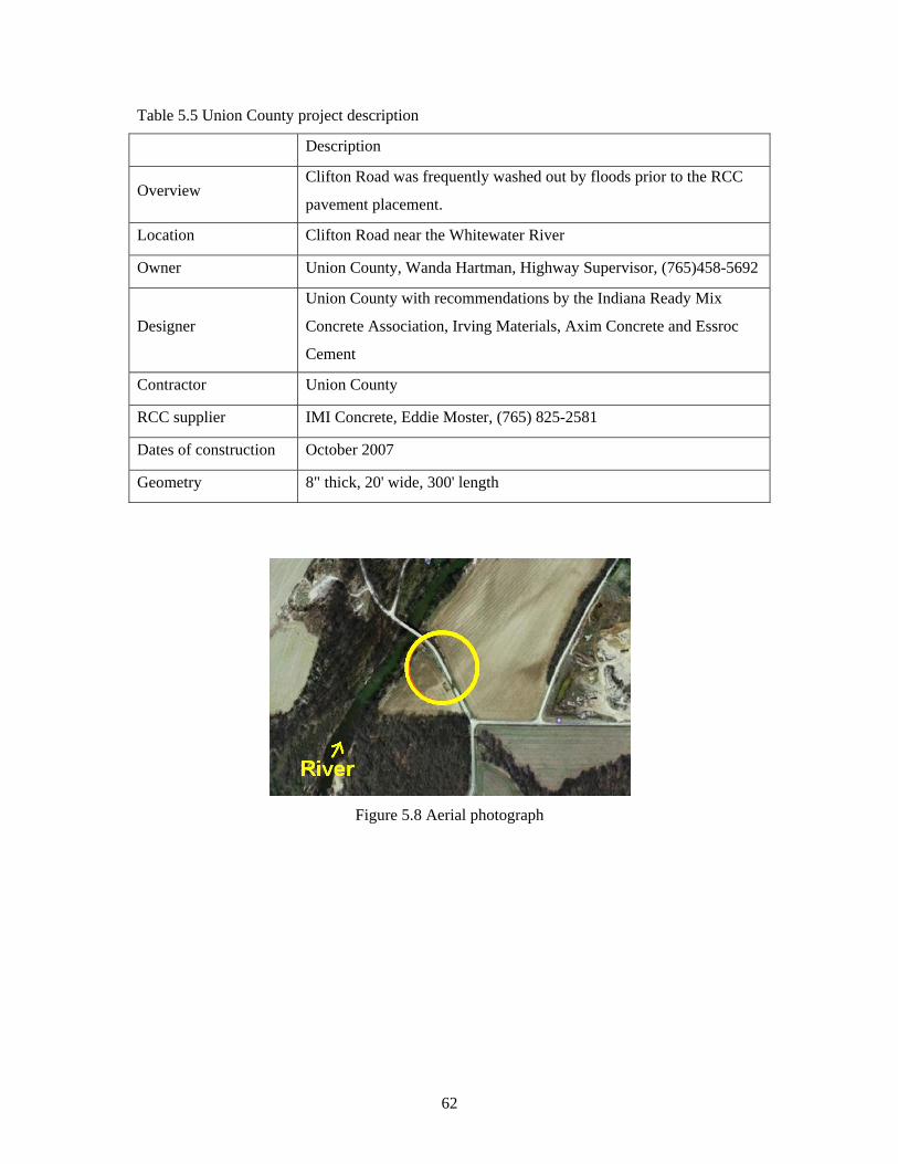
Table 5.5 Union County project description
Description
Overview Clifton Road was frequently washed out by floods prior to the RCC
pavement placement.
Location Clifton Road near the Whitewater River
Owner Union County, Wanda Hartman, Highway Supervisor, (765)458-5692
Designer
Union County with recommendations by the Indiana Ready Mix
Concrete Association, Irving Materials, Axim Concrete and Essroc
Cement
Contractor Union County
RCC supplier IMI Concrete, Eddie Moster, (765) 825-2581
Dates of construction October 2007
Geometry 8" thick, 20' wide, 300' length
Figure 5.8 Aerial photograph
62

(a) The transit mixer discharged the RCC mixture (b) RCC paving
(c) Compaction process (d) Samples fabricated with the RCC mixture
(e) (f) 1 year following construction: the RCCP remained in place after the flood event
Figure 5.9 Union County RCCP construction
63

6. References
1. AASHTO (1994) AASHTO Guide for Design of Pavement Structures, AASHTO, Washington,
D.C., 1994.
2. ACI 309.5 (2000) 309.5R-00: Compaction of Roller-Compacted Concrete, ACI Manual of
Concrete Practice, ACI, USA.
3. ACI 325.10 (2001) ACI 325.10R-95: State-of-the-art report on roller-compacted concrete
pavements, ACI Manual of Concrete Practice, ACI, USA.
4. ACI 325.12 (2002) ACI 325.12R: Guide for Design of Jointed Concrete Pavements for Streets
and Local Roads, ACI Manual of Concrete Practice, ACI, USA.
5. ACPA (2002) Design of Concrete Pavement for City Street, American Concrete Pavement
Association, Washington, D.C.
6. ACPA (2006) Design of Concrete Pavement for Street and Roads, American Concrete Pavement
Association, Washington, D.C.
7. ACPA (2010), StreetPave software: http://www.pavement.com/StreetPave/, American Concrete
Pavement Association, Washington, D.C.
8. Ambrose, Jimmy (2002) Beating Asphalt on Price. Concrete Producer, March.
9. Ashley, Erin (2008) Environmental and cost benefit of high albedo concrete, Concrete InFocus.
10. CAC (2005) Design and Construction of Roller-Compacted Concrete Pavements in Quebec,
Cement Association of Canada (CAC), p.111.
11. CP Tech Center (2010) Guide for Roller Compacted Concrete Pavements, National Concrete
Pavement Technology Center, August, p. 104
12. Delatte, Norbert (2004) Simplfied Design of Roller-Compacted Concrete Composite Pavement,
Journal of the Transportation Research Board, No. 1896, pp 57-65.
13. Gadja, Jonh and VanGeem, Martha G. (1997) A Comparison of Six Environmental Impacts of
Portland Cement Concrete and Asphalt Cement Concrete Pavement, R&D Serial No. 2068,
Portland Cement Association, Skokie, Illinois.
14. INDOT (2010) http://dotmaps.indot.in.gov/apps/trafficcounts/.
15. Johnson, Andy (2010) SCDOT Experience with RCC, Presentation in 38th Annual Highway
Conference http://www.clemson.edu/t3s/workshop/2009/hwyconf2009pres.htm.
16. Lee, Joo Hyoung and McCullouch, Bob (2009) Review Construction Techniques for Accelerated
Construction and Cost Implications, FHWA/IN/JTRP-2009/6, SPR-3201, Purdue University, p.
120.
64

65
17. Middlebrooks, T.A. and Bertram, G.E. (1942) Soil Tests for Design of Runway Pavements,
Highway Research Board Proceedings of the Twenty-Second Annual Meeting, Vol. 22, page 152.
18. Nanni , Antonio, Ludwig, Dennis A., and Shoenberger, James E. (1996) Physico-Mechanical
Properties and Load Transfer Efficiency of RCC Pavement, ACI Materials Journal, Vol. 93, Issue:
4, pp. 356-361.
19. PCA (1984) Thickness Design for Concrete Highway and Street Pavements, Portland Cement
Association, EB 109P, Skokie, Illinois.
20. PCA (2001) RCCPave software, Portland Cement Association, Skokie, Illinois.
21. PCA (2004) Guide Specification for the Construction of Roller Compacted Concrete Pavements,
Portland Cement Association, Skokie, Illinois.
22. PCA (2005) Roller-Compacted Concrete Pavements for Highways and Streets, Skokie, Illinois.
23. PCA (2006) Production of Roller-Compacted Concrete, Skokie, Illinois.
24. PCA (2009) Thickness Design of a Roller-Compacted Concrete Composite Pavement System,
Portland Cement Association, PL633, Skokie, Illinois.
25. PCA (2010) Columbus Embraces RCC Pavement,
http://www.cement.org/pavements/pv_rcc_columbus.asp.
26. Pictures (2010) Indiana Ready Mixed Concrete Association (IRMCA).
27. Poole, Bryant (2005) Roller Compacted Concrete: GDOT Applications, Presentation in RCC
Design Seminar in Atlanta, GA, http://www.secement.org/ rcc.htm.
28. Tate, Eddie (2010) Roller Compacted Concrete: A Municipal Perspective, Presentation at 2010
Tennessee Concrete Pavement Conference,
http://www.pavementse.com/TN_CPAT/2010_TCPC.htm.
29. U.S. Army Corp of Engineers (2000) Engineering and Design, Roller Compacted Concrete
Manual, No.1110-2-2006, January 15.
30. U.S. Army Corp of Engineers (2008) Unified Facilities Guide Specifications: Section 32 13 16.16
Roller Compacted Concrete Pavement, UFGS-32 13 16.16, November.

Appendix A
Contents
1. General Description
1.01 Description
1.02 Referenced Documents
1.03 Submittals
2. Materials
2.01 General Requirements
2.02 RCC Mix Criteria
3. Construction Requirements
3.01 General Requirements
3.02 Equipment
3.03 Preparation of Subgrade/ Subbase
3.04 RCC Mixing
3.05 RCC Transportation
3.06 Placing RCC
3.07 Weather Limitations
3.08 Compacting
3.09 Joints
3.10 Surface Finishing
3.11 Pavement Thickness
3.12 Curing
3.13 Opening to Traffic
Roller Compacted Concrete Pavement (RCCP) Guide Specification for Local Government Agencies
4. Quality Control and Assurance
4.01 Prescriptive Requirements
4.02 QC/QA Requirements
4.03 Treatment of Defective Pavement
5. Payment
5.01 Method of Measurement
5.02 Width and Length
5.03 Basis of Payment
6. Equipment
6.01 Mixing Plant
6.02 Paver
6.03 Compactors
6.04 Haul Trucks
6.05 Curing Equipment
6.06 Testing Facility and Equipment
7. Test Section
7.01 General Requirements
7.02 Strength Testing
A‐1

Roller Compacted Concrete Pavement (RCCP) Guide Specification for Local Government Agencies
Preface
This guide specification intends to provide guidance to local government agencies regarding the use of RCCP for the preparation of detailed construction specifications. The specification covers general requirements for materials, equipment, and construction. This specification targets local streets and roads in Indiana.
This specification uses the word “shall” to describe the Contractor’s responsibilities. The word “will” is used to describe the Agency’s responsibilities. The words “shall” and “will” are not required to be followed by the words “by the Contractor” or “by the Agency” to retain these meanings. “Engineer” means the agent who is in charge of the project in the “Agency.”
In this specification, the prescriptive requirements are specifically itemized, and quality control and assurance requirements are specified in Section 4.02. The Engineer will need to determine if the QC/QA requirements detailed in Section 4.02 are to be applied.
A‐2

Roller Compacted Concrete Pavement (RCCP) Guide Specification for Local Government Agencies
1. General Description 1.01 Description
This work shall consist of Roller-Compacted Concrete (RCC) pavement, RCCP, placed on a prepared subgrade or subbase in accordance with the INDOT Standard Specifications as modified herein.
Roller-Compacted Concrete (RCC) shall consist of aggregates, portland cement, supplementary cementing materials (fly ash, slag, or/and silica fume), water, and admixtures.
1.02 Referenced Documents
(a) Indiana DOT Standard Specifications (INDOT) Section 100 General Provisions Section 200 Earthwork Section 300 Aggregate Pavements and Bases Section 400 Asphalt Pavements Section 500 Concrete Pavement Section 900 Materials Details
(b) American Society for Testing and Materials (ASTM): C 42 Test Method for Obtaining and Testing Drilled Cores and Sawed Beams of
Concrete C 1040 Test Methods for Density of Unhardened and Hardened Concrete in Place by
Nuclear Methods C 1176 Practice for Making Roller-Compacted Concrete in Cylinder Molds Using a
Vibrating Table C 1435 Practice for Molding Roller-Compacted Concrete in Cylinder Molds Using a
Vibrating Hammer D 1557 Test Methods for Laboratory Compaction Characteristics of Soil Using
Modified Effort 1.03 Submittals
The contractor shall submit the following to the Engineer at least 5 business days before the start of any RCC pavement production:
(a) The Paving Plan shall be submitted to the Engineer. The Paving Plan shall include:
(1) Construction schedule for all RCC related operations. (2) Paving procedures describing the direction of paving operations, paving widths, planned longitudinal and transverse joints, compacting patterns, and curing methods.
A‐3

(b) Concrete Mix Design Submittal (CMDS) for RCCP shall be submitted and shall include the following:
(1) a list of all ingredients (2) the source of all materials (3) the gradation of the aggregates (4) the absorption of the aggregates (5) the SSD bulk specific gravity of the aggregates (6) the specific gravity of pozzolan (7) the batch weights (mass) (8) the names of all admixtures (9) the admixture dosage rates and the manufacturer’s recommended range (10) the compressive strength development. A minimum of 3 cylinders shall be tested at 28 days. (11) moisture-density relation, which shows the targeting density and optimum moisture content. (12) Any of the changes or adjustments to the mix design and CMDS shall be submitted for approval.
(c) Test Section (optional). If a test section is planned, the Engineer will determine the time necessary for the submittals and the placement of the test section prior to the start of paving operations to allow for the proper review time.. The results of the test shall be submitted as specified by the Engineer.
2. Materials 2.01 General
All materials to be used for RCC pavement construction shall be approved by the Engineer based on laboratory tests or certification of representative materials which will be used in the actual construction Materials shall be in accordance with the following:
Portland Cement 901.01(b) Fly Ash 901.02 Ground Granulated Blast Furnace Slag 901.03 Silica fume 901.04 Coarse Aggregate 904 Fine Aggregate 904 Water 913.01 Concrete Curing Materials 912.01 Admixtures 912.03
A‐4

2.02 RCC Mixture Criteria The RCC mixture shall meet the following requirements: (a) Aggregates gradation
The aggregate shall be well-graded without gradation gaps and conform to the following gradation recommended in PCA RCC guide specification (2004) unless otherwise approved by the Engineer in writing. Supplementary cementitious materials or unwashed sand may be used to supplement No. 100 and No. 200 fine grade aggregate contents.
Sieve Size Percent passing by weight 1" (25 mm) 100 3/4" (19 mm) 90-100 1/2" (12.5 mm) 70-90 3/8" (9.5 mm) 60-85 No. 4 (4.75 mm) 40-60 No. 16 (1.18 mm) 20-40 No. 100 (150 μm) 6-18 No. 200 (75 μm) 2-8
(b) Strength The mixture shall attain a minimum 28-day compressive strength of 5000 psi (38 MPa).
3. Construction Requirements 3.01 General
The construction sequences from production to compaction must be coordinated so that there is a continuous operation with no delays in any of the construction phases. Mixing, transporting, placing, and compaction must be planned accordingly. 3.02 Equipment
All necessary equipment shall be on hand and approved by the Engineer before work will be permitted. Roller-compacted concrete shall be constructed with any combination of equipment that will produce a completed pavement meeting the requirements for mixing, transporting, placing, compacting, finishing, and curing as provided in this specification. Details of equipment are specified in section 6. 3.03 Preparation of Subgrade/Subbase
The subgrade shall be shaped to the required grade and section, free from all ruts, corrugations, or other irregularities, and uniformly compacted and approved in accordance with INDOT Standard Specification Section 207 “Subgrade.” Surfaces on which a mixture is placed shall be free from objectionable or foreign materials at the time of placement.
A‐5
Subbase, if required, shall be placed and shaped to the required grade and section in accordance with INDOT Standard Specification Section 302; except, the drainage layer shall be omitted. 3.04 RCC Mixing (a) General
Except for minor variations in moisture content, the same mixture proportions shall be used for the entire project unless otherwise stated in the project documents. The water content shall be verified by the Contractor, as necessary but a minimum of once per day, to provide a consistency that is most conducive to effective placement and compaction. If a change is anticipated in the type or source of cementitious materials or aggregates, a mix design for those materials shall be developed and submitted prior to the start of construction. No changes to the materials submitted will be allowed without prior approval. (b) Mixture Ingredient Tolerances.
The mixing plant must receive the quantities of individual ingredients to within the following tolerances:
Material Variation in % by weight Cementitious materials +/- 1.0 Water +/- 1.0 Aggregates +/- 2.0
(c) Mixing time will be that which will assure complete and uniform mixing of all ingredients. The Engineer may require additional testing to verify uniformity of the mixture. (d) All material must be discharged before recharging. The mixing chamber and mixer blade surfaces must be kept free of hardened RCC or other buildup. Mixer blades shall be checked routinely for wear and replaced if wear is sufficient to cause inadequate mixing. 3.05 RCC Transportation
The RCC material shall be transported to the job site in dump trucks or transit mixers. These dump trucks should be equipped with covers in order to protect the RCC material from rain or excessive evaporation. The use of transit mixers involves the additional step of discharging into a dump truck at the plant or project site. For paver placed RCC, the dump trucks shall deposit the RCC material directly into the hopper of the paver or into a secondary material distribution system which deposits the material into the paver hopper. After unloading, all buildup and/or remaining RCC material must be fully cleaned from the trucks. Truck delivery must be scheduled so that RCC material is spread and compacted within the specified time limits.
A‐6

3.06 Placing RCC (a) Condition of the Subgrade/Subbase.
Prior to RCC placement, the surface of the subgrade/subbase shall be clean and free of foreign material, standing water and frost prior to the placement of the RCC pavement mixture. The subgrade/subbase must be moist at the time of RCC placement. If sprinkling of water is required to remoisten certain areas, the method of sprinkling shall not be such that it forms mud or pools of free-standing water. Prior to placement of RCC, the subgrade/subbase shall be checked for proper density and soft or yielding areas which shall be corrected as specified in Section 3.03. (b) Paver Requirements.
RCC shall be placed with an approved paver as specified in Section 6.02 and shall meet the following requirements:
(1) The quantity of RCC material in the paver shall not be allowed to approach empty between loads. The material shall be maintained above the auger shaft at all times during paving. (2) The paver shall operate in a manner that will prevent segregation and produce a smooth continuous surface without tearing, pulling or shoving. The amount of the RCC placed shall be limited to a length that can be compacted and finished within the appropriate time limit under the prevailing air temperature, wind, and climatic conditions. (3) The paver shall proceed in a steady, continuous operation with minimal starts and stops. Paver speed during placement operations shall not exceed the speed necessary to ensure that minimum density requirements are met and surface distress is minimized. (4) The surface of the RCC pavement as it leaves the paver shall be smooth, uniform and continuous without excessive tears, ridges or aggregate segregation.
(c) Lift Thickness. Lift thickness of compacted RCC pavement shall be as indicated in the Contract
Documents. An RCC pavement thickness greater than 8 inches (200 mm) is beyond the scope of this specification. No lift shall be less than 4 inches (100 mm). (d) Hand Spreading.
Broadcasting or fanning the RCC material across areas being compacted will not be permitted. Such additions of material may only be done immediately behind the paver and before any compaction has taken place. Any segregated coarse aggregate shall be removed from the surface before rolling.
A‐7

(e) RCC placement shall be done in a pattern so that the curing water from the previous placements will not pose a runoff problem on the fresh RCC surface or on the subbase layer. (f) Paving Inaccessible Areas.
Areas inaccessible to either paver or roller may be placed by hand and compacted with equipment specified in Section 6.03. These areas must satisfy all RCCP requirements. An alternate and preferred method for paving inaccessible areas is to use cast-in place INDOT Class A concrete or as specified by the Engineer. In areas that may be subjected to high load transfer, the Engineer may require the cast-in-place concrete to be smooth doweled into the RCC. (g) Placement of RCC with graders, dozers or other alternative paving equipment as specified in Section 6.02 shall meet the requirements of paver placed RCC where applicable. (h) Manhole castings shall be installed after a block of RCC over the manhole location is removed. Cast-in place INDOT Class A concrete shall be used to fill the remaining void. Manholes and castings can be installed as specified by the Engineer.
3.07 Weather Limitations
(a) Cold weather RCC material shall not be placed on any surface containing frost or frozen material. The
RCCP shall be placed when the air temperature is at least 35°F (2°C) and rising. When the air temperature is expected to fall below 40°F (4°C), the Contractor must present to the Engineer a detailed proposal for protecting the RCC pavement. This proposal must be accepted by the Engineer before paving operations may be resumed. A sufficient supply of protective material such as insulating blankets, plastic sheeting, straw, burlap or other suitable material shall be provided by the Contractor at his expense. The methods and materials used shall be such that a minimum temperature of 40°F (4°C) at the pavement surface will be maintained for a minimum of five days. Approval of the Contractor‘s proposal for frost protection shall not relieve the Contractor of the responsibility for the quality and strength of the RCC placed below the specified temperatures. Any RCC that freezes shall be removed and replaced at the Contractors expense. (b) Hot weather
During periods of hot weather or windy conditions, special precautions shall be taken to minimize moisture loss due to evaporation. Under conditions of excessive surface evaporation due to a combination of air temperature, relative humidity, concrete temperature and wind conditions, the Contractor must present to the Engineer a detailed proposal for minimizing moisture loss and protecting the RCC. Precautions may include cooling of aggregate stockpiles by use of a water spray, protective covers on dump trucks, temporary wind breaks to reduce wind effect, cooling of concrete mix water, and decreasing the allowable time between mixing and final compaction.
A‐8

(c) Rain Limitations. No placement of RCC pavement shall be done while it is raining hard enough to be detrimental to the finished product. Placement may continue during light rain or mists provided the surface of the RCC pavement is not washed-out or damaged due to tracking or pickup by dump trucks or rollers. Dump truck covers must be used during these periods. The Engineer will be the sole judge as to when placement must be stopped due to rain.
3.08 Compacting
(a) Compaction shall begin within 10 minutes of spreading, except for fresh joints, and shall be completed within 60 minutes of the start of plant mixing. The time may be increased or decreased at the discretion of the Engineer depending on use of set retarding admixtures or ambient weather conditions of temperature, wind and humidity. (b) Rolling. The Contractor shall determine the sequence and number of passes by vibratory and non-vibratory rolling to obtain the minimum specified density and surface finish.. Vibratory rollers shall not remain stationary in vibratory mode. Pneumatic-tire rollers may be used during final compaction to knead and seal the surface. (c) Rolling Longitudinal and Transverse Joints. The roller shall not operate within 12 in. (300 mm) of the edge of a freshly placed lane until the adjacent lane is placed. Then both edges of the two lanes shall be rolled together within the allowable time. If a cold joint is planned, the complete lane shall be rolled and cold joint procedures, as specified in Section 3.09 (b) shall be followed. (d) Longitudinal joints shall be given additional rolling as necessary to produce the specified density for the full depth of the lift and a tight smooth transition occurs across the joint. Any uneven marks left during the vibratory rolling shall be smoothed out by non-vibratory or rubber tire rolling. The surface shall be rolled until a relatively smooth, flat surface, reasonably free of tearing and cracking is obtained. (e) Speed of the rollers shall be slow enough at all times to avoid displacement of the RCC pavement. Displacement of the surface resulting from reversing or turning action of the roller shall be corrected immediately. (f) Areas inaccessible to large rollers shall be treated as specified in Section 3.06 (f). (g) Density Requirements.
The required density shall be not less than 98% of the maximum wet density obtained by ASTM D 1557 or equivalent test method based on a moving average of five consecutive tests with no test below 95%.
A‐9

3.09 Joints (a) Fresh Vertical Joints
A vertical joint shall be considered a fresh joint when an adjacent RCC lane is placed and compacted within 60 minutes of the RCC mixing of the previous lane, with the time adjusted depending on use of retarders or ambient conditions. Fresh joints do not require special treatment. (b) Cold Vertical Joints
Any planned or unplanned construction joints that do not qualify as fresh joints shall be considered cold joints and shall be treated as follows:
(1) Longitudinal and Transverse Cold Joints Formed joints that do not meet the minimum density requirements of Section
3.08 (g) and all unformed joints shall be cut and removed as detailed below for the full length of the joint. The vertical cut shall be at least 6 in (150 mm) from the exposed edge. Cold joints cut within two hours of placement may be cut with an approved wheel cutter, motor grader or other approved method provided that no significant edge raveling occurs. Cold joints cut after two hours of placement shall be saw cut 1/3 the depth of the RCC pavement with the rest removed by hand or mechanical equipment. Any modification or substitution of the saw cutting procedure must be demonstrated to and accepted by the Engineer. All excess material from the joint cutting shall be removed. (2) Prior to placing fresh RCC mixture against a compacted cold vertical joint, the joint shall be thoroughly cleaned of any loose or foreign material. The vertical joint face shall be wetted and in a moist condition immediately prior to placement of the adjacent lane.
(c) RCC Pavement Joints at Structures.
The joints between RCC pavement and concrete structures shall be treated as cold vertical joints unless noted by the Engineer. (d) Control Joints
Control joints, if required, may be constructed in the RCC pavement to induce cracking at pre-selected locations. Joint locations shall be detailed in the Contract Documents or as directed by the Engineer. Early entry saws should be utilized as soon as possible behind the rolling operation and set to manufacturer’s recommendations. Conventionally cut control joints shall be saw cut to 1/3 depth of the compacted RCC pavement. Joints shall be saw cut as soon as those operations will not result in significant raveling or other damage to the RCC pavement.
(e) Isolation Joints Isolation joints, if required, may be constructed in the RCC pavement to isolate fixed
structures occurring within or along the pavement boundaries, such as building foundation slabs, gutters, and manholes, to allow for differential horizontal and vertical movement.
A‐10

3.10 Surface Smoothness The finished surface of the RCC pavement, when tested with a 10 foot (3 meter) straight
edge or crown surface template, shall not vary from the straight edge or template by more than 1/2 inch (12 mm) at any one point. When the surface smoothness is outside the specified surface tolerance the Contractor shall grind the surface to within the tolerance by use of self-propelled diamond grinders. Milling of the final surface is not acceptable, unless it is for the removal of the pavement.
3.11 Pavement Thickness The thickness of the RCC pavement shall not deviate from that detailed in the Contract
Documents or as directed by the Engineer by more than minus 1/2 inch (12.5 mm). Pavement of insufficient thickness shall be removed and replaced the full depth. No skin patches shall be accepted.
3.12 Curing
(a) Within 60 minutes after final rolling, RCCP shall be cured with an approved white pigmented liquid membrane forming compound. Curing shall be in accordance with INDOT Standard Specification Section 504.04. (b) When a surface treatment or application will be applied at the same day, curing with a membrane forming liquid compound shall not be used. The surface shall be kept moist until the surface treatment is applied.
3.13 Opening to Traffic
The Contractor shall be responsible for controlling the opening of the RCCP to construction and non-construction traffic. (a) Construction
Construction vehicles or equipment may be allowed on the new pavement prior to its opening to traffic as approved by the Engineer. Approved joint cutting saws may be operated on the RCCP. (b) Non-construction
The RCCP may be opened when the measured compressive strength is 3500 psi (26 MPa) or greater. If adequate strengths are not met within 7 days, an investigation by the Engineer and Contractor will be conducted to determine if the RCCP is deficient.
Alternatively, at the discretion of the Engineer, the RCCP may be opened to light weight traffic (less than 11,000 lbs G.V.W) after 5 hours of placement. Heavy weight traffic may be permitted after 24 hours of placement.
A‐11

4. Quality Control and Quality Assurance 4.01 Prescriptive Requirements
(a) General Requirements
The Contractor shall ensure that the moisture contents of materials are monitored daily, the mixture proportions are adjusted considering the moisture contents, required density is achieved, and the RCCP is properly constructed according to the Contract Documents. (b) Thickness Assurance
Measured thickness shall meet the requirement of Section 3.11. The Engineer will determine whether a deficient pavement will be removed and replaced at no cost to the agency or left in place with no payment.
RCCP thickness will be determined by cores obtained after corrective grinding. If a core shows that the pavement is more than 1/2 in. (13mm) deficient in thickness, additional cores shall be taken in accordance with INDOT Standard Specification Section 502.21.
RCCP thickness can be measured taken during the paving process when core samples are not planned. (c) The Engineer or Independent laboratory may take core samples to verify the strength, density or/and thickness of the pavement at the discretion of the Engineer.
4.02 QC/QA Requirements
(a) Field Density Control In-place field density tests shall be performed in accordance with ASTM C 1040, direct
transmission, as soon as possible, but no later than 30 minutes after completion of rolling. A minimum of 2 density measurements shall be taken for every 600 square yards of pavement.
Only wet density shall be used for evaluation. Measured density shall meet the requirements specified in Section 3.08. Other methods may be used with the Engineer’s approval.
(b) Strength Assurance
The strength of the RCCP will be determined from 2 sets of 2 cores for each 2400 sq yd. of pavement.
Each core will be tested for compressive strength in accordance with ASTM C 42 and/or for thickness. The cores will be submerged in lime saturated water for a minimum of 40 hours prior to strength testing.
A‐12

The Contractor shall obtain cores at the locations determined by the Engineer in accordance with ITM 802. In the presence of the Engineer, Cores 4 in. (100 mm) in diameter shall be taken for the full depth of the RCCP. The Engineer will take immediate possession of the cores. Cores shall not be taken within 2 ft (0.6 m) of the edge of the RCCP or within 5 ft (1.5 m) of a transverse construction joint. All core holes shall be filled with PCC or rapid setting patch material within 24 h of drilling.
Average RCCP strength for test core samples shall be at least 4250 psi, which is 85% of the required strength. The Engineer will determine whether a deficient pavement will be removed and replaced at no cost to the agency, or left in place with no payment.
4.03 Treatment of Defective Pavement
(a) Pavement Inspection The Contractor and Engineer will conduct an inspection of the new RCCP for any defects
and/or damage. (b) Defective areas are best repaired while the RCC is still plastic (before the compaction starts), otherwise repairs shall be conducted after a 7-day period. All repairs are subject to the Engineer’s approval. No additional payment will be made for the repair, or removal and replacement, of defective pavement. (c) Skin-patching of an area that has been rolled is not permitted. (d) Pavement removal and replacement
After 7 days, defective pavements shall be removed and replaced or left in place with no payment. Conventional concrete or RCC may be used to fill the void. The new slab shall conform to all requirements stated herein. In areas that may be subjected to high load transfer, the Engineer may require the cast-in-place concrete to be doweled into the RCC.
5. Payment 5.01 Method of Measurement
RCCP will be measured by the square yard (square meter) of the thickness specified. The area of the RCCP will consist of the planned width of the pavement multiplied by the length of the pavement, or as otherwise directed in the Contract Documents.
5.02 Width and length
The width of the pavement will be as detailed in the Contract Documents. The length of the pavement will be measured parallel to the surface of the pavement along the centerline of the roadway or ramp, excluding paving exceptions as shown in the Contract Documents.
A‐13

5.03 Basis of Payment The accepted quantities of RCCP will be paid for at the contract unit price per square
yard (square meter) of completed and accepted RCC pavement.
Pay Item Pay Unit Symbol RCCP, , in. (mm) ............. .... ...... square yard (m2)
(thickness)
The price shall include all material costs, mixing, hauling, placement, compaction, curing, inspection, testing, testing assistance and all other incidentals. Such payment shall constitute full reimbursement for all work necessary to complete the RCC pavement.
If a test section is constructed, it will be paid for on a lump sum basis. Such payment shall constitute full reimbursement for all materials, labor, equipment, mobilization, demobilization, testing, and all other incidentals necessary to construct and test the test section.
6. Equipment 6.01 Mixing Plant
(a) The mixing plant shall be in accordance with INDOT Standard Specification Section 508.02. (b) The volume of RCC material in the mixing chamber shall not be more than the rated capacity for dry concrete mixtures. (c) The plant shall be located within a 30 minute haul time from the RCC placement location. With prior testing and Engineer approval, a set retarding admixture may be used to extend the haul time.
6.02 Paver
(a) RCC shall be placed with a high-density paver, or a conventional asphalt paver in accordance with INDOT Standard Specification Section 409.03. The paver shall be of suitable weight and stability to spread and finish the RCC material, without segregation, to the required thickness, smoothness, cross-section and grade. (b) Alternative Paving Equipment.
Any alternative paving equipment such as graders and dozers must be approved by the Engineer prior to use. The equipment shall be capable of producing a finished product that results in a smooth, continuous surface without segregation, excessive tearing, or rock pockets.
A‐14

6.03 Compactors (a) Self-propelled steel drum vibratory rollers having a minimum static weight of 10 tons (9.07 metric tons) shall be used for primary compaction. For final compaction either a steel drum roller, operated in a static mode, or a pneumatic-tire roller shall be utilized. (b) Walk-behind vibratory rollers or plate compactors shall be used for compacting areas inaccessible to the large rollers.
6.04 Haul Trucks
Trucks for hauling the RCC material from the plant to the paver shall have covers available to protect the material from rain or excessive evaporation. The number of trucks shall be sufficient to ensure an adequate and continuous supply of the RCC material to the paver.
6.05 Curing Equipment
(a) Proper equipment shall be provided in accordance with INDOT Standard Specification Sections 504 and 508.05. (b) At least one water truck, or other similar equipment, shall be on-site and available for use throughout the paving and curing processes in case of a sudden delay or incident during the construction. Such equipment shall be capable of evenly applying a fine spray of water to the surface of the RCC without damaging the final surface.
6.06 Testing Facility and Equipment
(a) Testing Facilities and Equipment shall be furnished in accordance with INDOT Standard Specification Section 508.09 (b) Nuclear Density Gauge
One operable and properly calibrated nuclear density gauge shall be furnished for each paver. The nuclear density gauge shall be made available for the Engineer’s use upon request. The nuclear density apparatus shall conform to ASTM C 1040/C 1040M, method A – direct transmission, and shall be of a single-probe type.
A‐15

A‐16
7. Test Section 7.01 General Requirements
(a) The Engineer may include a test section in the contract documents to insure means, methods and results are suitable and anticipated. “Roll down,” placed thickness to compacted thickness, of the mixture as well as density and other factors can be verified with a test section. (b) The Engineer will determine the time necessary for the placement of the test section prior to the start of paving operations to allow for the proper review time. The Contractor shall construct a test section using the trial mix design. This test pavement will allow the Engineer to evaluate the strength of the RCC material, methods of construction, curing process and surface conditions of the completed test pavement. The test section shall be at least 50 feet (15 meters) long and a minimum of two paver widths wide. It shall be located in a non-critical area or as indicated in the Contract Documents. The test pavement will be constructed over an extended period to demonstrate the construction of cold joints in both a longitudinal and transverse direction, as well as fresh joint construction. (c) The equipment, materials and techniques used to construct the test section shall be that which will be used to construct the main RCC pavement. (d) During construction of the test section the Contractor will establish an optimum rolling pattern and procedure for obtaining a density of not less than 98% of the maximum wet density in accordance with ASTM D 1557 or equivalent test method. In addition, the Contractor must also demonstrate the ability to achieve a smooth, hard, uniform surface free of excessive tears, ridges, spalls and loose material.
7.02 Strength Testing (a) Field Cast Specimens.
Specimens shall be prepared in accordance with ASTM D 1557, ASTM C 1435, or ASTM C 1176. Cure and transport specimens to the laboratory in accordance with ASTM C 31. Specimens shall be tested for splitting tensile strength (ASTM C 496) and compressive strength (ASTM C 39) at 7, 14, and 28 days of age. (b) Cores and Beams.
The test section shall be cured at least 5 days prior to extracting cores and beams for testing. The cores and beams shall be obtained in accordance with ASTM C 42. The cores will be tested for splitting tensile strength (ASTM C 496) and compressive strength (ASTM C 39) at 7, 14 and 28 days of age. In addition, 6x6x21 in. (150x150x525 mm) beams will be sawn from the test section and flexural strength at 7, 14 and 28 days will be determined in accordance with ASTM C 78.

Appendix B. Special Provision Examples
Special Provisions (example)
ROLLER COMPACTED CONCRETE PAVEMENT
A. DESCRIPTION: This work shall consist of furnishing and paving Roller Compacted Concrete in accordance with the RCC Specification provided.
B. MATERIAL: The material in these items shall be in accordance with Section 2 of the RCC
Specification except as modified below.
C. GENERAL REQUIREMENTS: The following RCC Specifications shall be used for the designated RCC for this project.
1. The RCCP shall be constructed without QC/QA requirements, and without a test section. 2. The Contractor shall submit the paving plan and the mix design submittals for approval
in accordance with the RCC Specification at least 5 business days before the start of any RCC pavement production.
3. A minimum compressive strength of the RCC is 5,000 psi at 28 days as fabricated by ASTM C 1435 and measured by ASTM C 42.
4. Compacted RCC shall achieve a minimum of 98% maximum wet density as measured by ASTM C 1040. No single test shall be below 95%.
5. The Contractor will be allowed to close the road for a 7 day period to cure the RCC and to perform all work.
6. All work and material shall follow the 2010 Indiana Department of Transportation Standards, Specifications, and Supplemental Specifications as updated and revised.
D. METHOD OF MEASUREMENT: The RCC pavement will be measured in accordance with
Section 5 of the RCC Specification. E. BASIS OF PAYMENT: The accepted quantities of RCC pavement will be paid at the contract
unit price per square yard in accordance with Section 6 of the RCC Specification. The unit price shall include all material and construction costs such as placement, compaction, curing, inspection, testing, testing assistance and all other incidental operations.
Pay Item Pay Unit
Roller Compacted Concrete Pavement Square yard
B‐1

Special Provisions (example)
ROLLER COMPACTED CONCRETE PAVEMENT
A. DESCRIPTION: This work shall consist of furnishing and paving Roller Compacted Concrete in accordance with the RCC Specification provided.
B. MATERIAL: The material in these items shall be in accordance with Section 2 of the RCC
Specification except as modified below.
C. GENERAL REQUIREMENTS: The following RCC Specifications shall be used for the designated RCC for this project.
1. The RCCP shall be constructed with QC/QA requirements, and without a test section. 2. The Contractor shall submit the paving plan and the mix design submittals for approval
in accordance with the RCC Specifications at least 5 business days before the start of any RCC pavement production.
3. A minimum compressive strength of the RCC is 5,000 psi at 28 days as fabricated by ASTM C 1435 and measured by ASTM C 42. An independent laboratory will verify the core strength, which shall be at least 4250 psi at 28 days.
4. Compacted RCC shall achieve a minimum of 98% maximum wet density as measured by ASTM C 1040. No single test shall be below 95%. The Contractor will perform the in-place density measurement.
5. The Contractor will be allowed to close the road for a 7 day period to cure the RCC and to perform all work.
6. All work and material shall follow the 2010 Indiana Department of Transportation Standards, Specifications, and Supplemental Specifications as updated and revised.
D. METHOD OF MEASUREMENT: The RCC pavement will be measured in accordance with
Section 5 of the RCC Specification. E. BASIS OF PAYMENT: The accepted quantities of RCC pavement will be paid at the contract
unit price per square yard in accordance with Section 6 of the RCC Specification. The unit price shall include all material and construction costs such as placement, compaction, curing, inspection, testing, testing assistance, and all other incidental operations.
Pay Item Pay Unit Roller Compacted Concrete Pavement Square yard
B‐2

B‐3
Special Provisions (example)
ROLLER COMPACTED CONCRETE (When County constructs the pavement by themselves)
A. DESCRIPTION: This work shall consist of furnishing Roller Compacted Concrete in accordance with the RCC Specification provided.
B. MATERIAL: The material in these items shall be in accordance with Section 2 of the RCC
Specification except as modified below.
C. GENERAL REQUIREMENTS: The following RCC Specifications shall be used for the designated RCC for this project.
1. The Supplier shall submit the mix design submittals for approval in accordance with the RCC Specifications at least 5 business days before the start of any RCC production.
2. A minimum compressive strength of the RCC is 5,000 psi at 28 days as fabricated by ASTM C 1435 and measured by ASTM C 42.
3. Compacted RCC shall achieve a minimum of 98% maximum wet density as measured by ASTM C 1040.
4. All material shall follow the 2010 Indiana Department of Transportation Standards, Specifications, and Supplemental Specifications as updated and revised.
D. BASIS OF PAYMENT: The accepted quantities of RCC will be paid for at the contract unit
price per cubic yard.
Pay Item Pay Unit Roller Compacted Concrete Cubic yard

Appendix C. Construction Planning Guidelines
Contents
1. Introduction ........................................................................................................................................... 2
2. Paving Parameter Estimation ................................................................................................................ 3
2.1 Supply Rate and Delivery Time .................................................................................................... 3
2.1.1 Transit Mixer ........................................................................................................................ 4
2.1.2 Central Batch Mixer .............................................................................................................. 7
2.2 Estimation of Paver Speed and Paving Time ................................................................................ 9
3. Paving Plan ......................................................................................................................................... 12
3.1 Continuous Paving ...................................................................................................................... 12
3.2 Discontinuous Paving ................................................................................................................. 13
3.2.1 Elapsed Time for Construction Joints ................................................................................. 13
3.2.2 Construction of 2 Adjacent Lanes with 1 Paver .................................................................. 15
3.2.3 Construction of 3 or More Adjacent Lanes with 1 Paver .................................................... 17
3.3 Examples ..................................................................................................................................... 20
C‐1
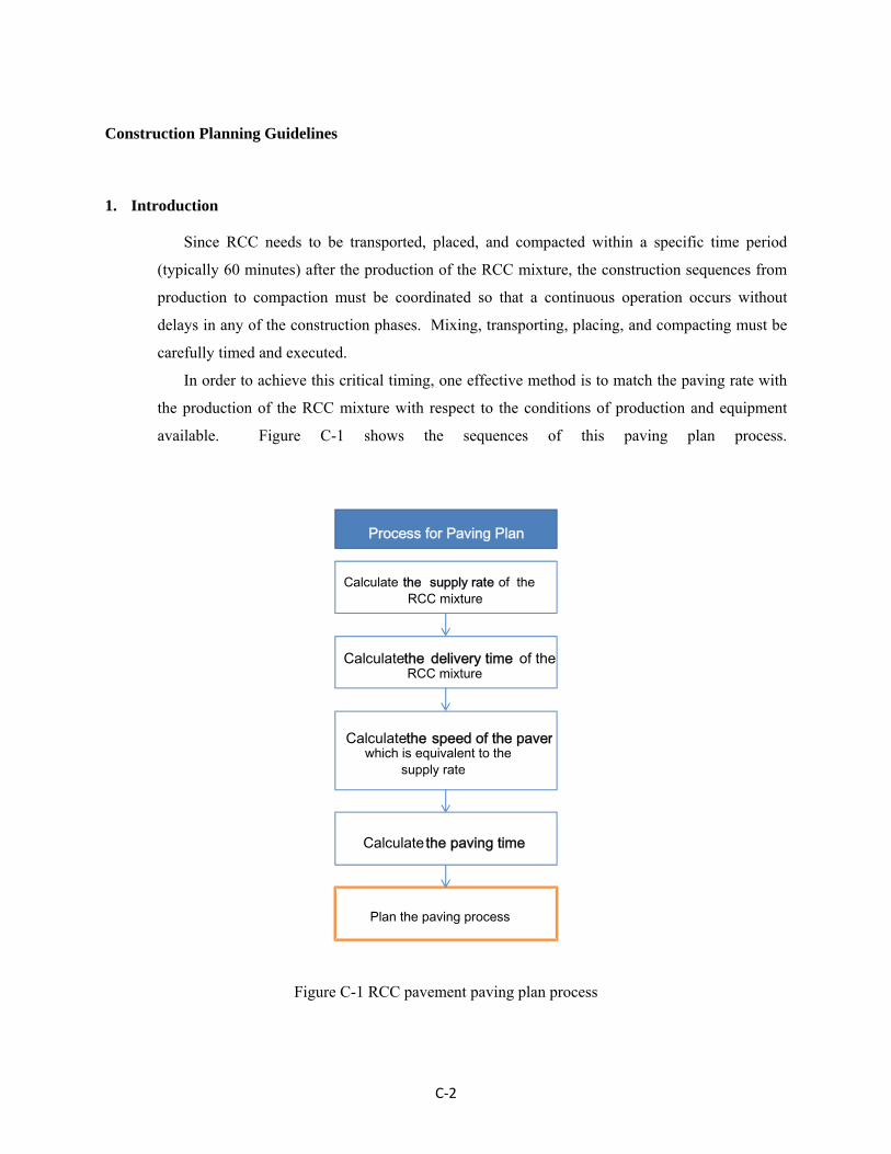
Construction Planning Guidelines
1. Introduction
Since RCC needs to be transported, placed, and compacted within a specific time period
(typically 60 minutes) after the production of the RCC mixture, the construction sequences from
production to compaction must be coordinated so that a continuous operation occurs without
delays in any of the construction phases. Mixing, transporting, placing, and compacting must be
carefully timed and executed.
In order to achieve this critical timing, one effective method is to match the paving rate with
the production of the RCC mixture with respect to the conditions of production and equipment
available. Figure C-1 shows the sequences of this paving plan process.
Calculatethe delivery time of theRCC mixture
Calculatethe speed of the paver which is equivalent to the
supply rate
Calculate the supply rate of the RCC mixture
Calculate the paving time
Process for Paving Plan
Plan the paving process
Figure C-1 RCC pavement paving plan process
C‐2

2. Paving Parameter Estimation
2.1 Supply Rate and Delivery Time
The supply rate and delivery time are key factors in determining the RCC paving plan.
The supply rate can be used to determine the paver speed. The delivery time can be used for
determining the paving time needed for the RCC mixture to be placed and compacted.
Therefore, the RCC mixture supply rate and delivery time need to be estimated in advance.
Since the RCC mixture production consists of several processes such as batching, mixing,
transporting, and discharging, the slowest rate amongst these processes determines the critical
supply rate of the whole production process. For example, even though the production rate at
the plant is high, the supply rate of the mixture at the job site will be reduced if the number of
trucks is insufficient to transport the mixtures in a timely fashion.
Because RCC is typically produced at the same production facilities as concrete, it can be
mixed and delivered in two different ways. For a central mixed RCC, the mixture is
completely mixed at the plant, then transported using dump trucks or transit mixers to the job
site. For a transit mixed RCC, materials are batched at a plant and transported using transit
mixers. The material can be transferred to dump trucks in the plant or at the job site. The
mixture is transported to the paver in those dump trucks. Each requires its own timing;
therefore, the supply rate and delivery time need to be calculated differently with respect to the
production and transportation methods.
Figure C-2 Various transfer methods of RCC mixtures to dump trucks
when the RCC is produced by transit mixers
C‐3

2.1.1 Transit Mixer
Figure C-3 demonstrates the production and delivery processes of transit-mixed RCC.
The supply rate and delivery time can be estimated using this figure.
Batch Transport Mix
Batch and transit mixer
ProductionRate : Qp
Transfer Discharge
Plant Dump truckTransit mixer
ttm tdttmix
Time
Paver
MixtureVolume Ntm*qtm Ndt*qdt
Qtm=Ntm*qtm / (2*ttm+tmix+tdis) Qt= Ndt*qdt / (2*tdt)Mix rate Transfer rate
Discharge
tdis
Delivery time
Rate
Qtm : mix ratettm : transport time of a transit mixertmix : mix time tdis : discharge timeNtm : number of transit mixersqtm : capacity of one transit mixer
Qtm : transfer ratetdt : transfer time of a dump truckNdt : number of dump trucksqdt : capacity of one dump truck
Figure C-3 Supply rate and delivery time for dry batched RCC
A. Supply rate
The RCC is batched at a plant, transported and mixed in transit mixers, and finally
transferred to dump trucks. Therefore, the process has three steps: 1) production, 2) mixing,
and 3) transfer. The rates for these processes can be calculated as follow:
a. Production rate (batch): Qp
For a dry batch mixture, the plant batch rate is the production rate (Qp).
C‐4

b. Mix rate (transport and mix): Qm
Since the RCC is completely mixed in the transit mixers during/after the transportation
process, the RCC mixing rate can be estimated by multiplying the mixing rate of one
transit mixer by the number of transit mixers used. The mixing rate of one transit mixer
can be calculated by dividing the capacity of a transit mixer by the time taken for
transporting, mixing, and discharging. The mixing rate can be calculated as follows:
Qm = Ntm*qtm / ((2*ttm) + tmix + tdis)
where Ntm is the number of transit mixers, qtm is the RCC capacity of a transit mixer, and
ttm, tmix, and tdis are the times for transporting, mixing and discharging the RCC.
For a transit mixer, the normal mixing volume is 5-6 cubic yards per 10 cubic yards
of capacity load. This can be modified depending on the type of dump trucks being used.
The mixing time is approximately 1 minute per cubic yard, and the discharge into a dump
truck is about 1 minute per cubic yard (PCA 2006).
c. Transfer rate: Qt
When the RCC mixture is produced in a transit mixer, it needs to be transferred to the
dump trucks, and then discharged into pavers. This transfer rate can be calculated by
dividing the capacity of the dump trucks by the delivery time as following:
Qt= Ndt*qdt / (2*tdt)
where Ndt is the number of dump trucks, qdt is the RCC capacity of a dump truck, and tdt
is the time required to haul the RCC mixture.
For a transit mixer, the amount of RCC loaded in a dump truck is usually the same as
that of the transit mixer. For a conservative estimate, the truck waiting time for
discharging the RCC mixture into the pavers at the job site can be included in the dump
truck hauling time (tdt).
d. Supply rate: Qsup
The critical supply rate (Qsup) for the RCC mixture is the slowest rate involved in the
RCC production, mix, and transfer processes.
Qsup = Minimum (Qp, Qm, Qt)
C‐5

B. Delivery time: td
The delivery time (td) is the duration from the initial water-cement contact to the
moment of discharge into the paver. When the mixture is mixed at the site, the delivery
time is the summation of the discharge and transfer time. However, when the water
contacts the cement at the plant, the mix and transport times (ttm, tmix) also need to be
included in the delivery time.
td = tdis + tdt (+ ttm+ tmix)
C. Example
Given conditions:
- Production (batch) rate: 50 cys/hr
- Transit mixer
Number of transit mixers: 4
Volume loaded in the transit mixer: 5 cys
Transport time of the RCC from the batch plant to the site: 10 min.
Mix time: 5 min.
Discharge time: 5 min.
Water contact cement at the plant
- Dump trucks
Number of dump trucks: 2
Capacity of dump trucks: 5 cys
Duration from loading to discharge: 7 min.
Then, the production rate is:
Qp=50 cys/ 1 hr (60 minutes) = 0.833 cys/ 1 min
the mix rate is:
Qm=4 transit mixers *5 cys/((2*10 min)+5 min+5 min)= 0.667 cys/1 min
the transfer rate is:
Qt= 2 trucks * 5cys / (2*7 min) = 0.714 cys/ 1 min
C‐6

Therefore, the critical supply rate Qsup is 0.667 cys/min, which is determined by
the mix rate.
Since the water contacts the cement at the plant, the delivery time is 27 minutes.
td = 10 min +5 min +5 min +7 min =27 min
2.1.2 Central Batch Mixer
Figure C-4 demonstrates the production and delivery processes of a central mixed
RCC. The supply rate and delivery time can be estimated using this figure.
Batch Mix
Central batch mixer
Production RateQp
Haul Discharge
Plant Dump truck
Time
Paver
MixtureVolume
Discharge
tdis
Delivery time
Rate
tdt
Ndt*qdt
Qt= Ndt*qdt / (2*tdt)Transport rate
Qt : transport ratetdt : transport time of a dump truckNdt : number of dump trucksqdt : capacity of one dump truck
Figure C-4 Supply rate and delivery time for central batched RCC
C‐7

A. Supply rate
For a central batch mixer, the mixture is batched and mixed at the plant. Therefore,
the supply rate is the minimum rate of the production and transportation processes.
a. Production rate (batch and mix): Qp
For the central batch plant, the production rate in the plant is Qp. The typical
production rate of the central batch mixer is 50-100 cys/hr. For a tilt drum mixer, the
typical mix time is 2-4 minutes. For a horizontal compulsory mixer, mixing takes 20-60
seconds for up to 12 cys of a batch size (PCA 2006).
b. Transport rate: Qt
When the RCC mixture is produced at a plant, it needs to be transported to the site in
dump trucks or transit mixers. This transport rate can be calculated by dividing the dump
trucks capacity by the delivery time as follows:
Qt= Ndt*qdt / (2*tdt)
For a conservative estimate, the truck waiting time for discharging the RCC mixture into
the pavers at the job site can be included in the dump truck hauling time (tdt).
c. Supply rate: Qsup
The critical supply rate (Qsup) for the RCC mixture, which is transported to the
pavers, is the slowest rate involved in the RCC production and transport processes.
Qsup = Minimum (Qp, Qt)
B. Delivery time
The delivery time (td) is the time taken to transport the mixture from the plant to
pavers. Since the mix and discharge time is relatively short, only the hauling time is
included in the calculation of the delivery time. For a conservative estimate, the mix,
discharge, and truck waiting time need to be included in the delivery time.
td = tdt
C‐8

C. Example
Given conditions
Production (batch and mix) rate: 100 cys/hr
Dump trucks
Number of dump trucks: 6
Capacity of dump trucks: 7 cys
Duration from mix to discharge into the paver: 15 min.
Then, the production rate is:
Qp = 100 cys / 1 hr = 1.667 cys / 1 min
The transport rate is:
Qt = 6 trucks * 7 cys / ( 2*15 min) = 1.4 cys / 1 min
Therefore, the critical supply rate (Qsup) is 1.4 cys/minute, and the delivery time (td) is 15
minutes
2.2 Estimation of Paver Speed and Paving Time
Using the delivery time and supply rate, the paver speed and the paving time can be estimated.
A. Estimated Paving Time
Construction joints must be compacted within a specific time period (tcr) in order to
create fresh joints in the pavement. This critical time is typically 60 minutes after mixing
(water-cement contact), although it depends on the weather conditions and mixture
characteristics, see section 4.2.1 for details. The estimated paving time, tpav, can be
calculated as follows:
tpav = tcr – td
where tcr is the critical time available to create fresh joints.
C‐9

When the critical time, tcr, is assumed to be 60 minutes, the estimated paving time will be:
tpav = 60 min- td
If a retardation agent is used or the weather is cold, tcr can increase. Meanwhile, in hot or
windy weather, tcr should decrease.
B. Estimated Paver Speed
In order to minimize the starts and stops of the paver, which can cause potential
problems in the construction process, the paving rate, Qpav, needs to be balanced with the
RCC supplying rate. One effective method for matching the paving rate with the RCC
production is to adjust the paver speed with respect to the RCC supply rate. Assuming
that the paving rate is equal to the supply rate results in the following:
Qsup = Qpav = Npav*vpav*t*w
where Npav and vpav are the number and speed of the pavers and t and w are the thickness
and width of the one paver lane. Then, the speed of the pavers can be determined as
follows:
v QN
The paving can be planned using this estimated paver speed as long as the speed is in a
reasonable range. It is reported that there is no significant difference in lay-down density
at speeds ranging from 7 to 12 feet per minute (Nanni et al 1996).
However, when the estimated paver speed is greater than the upper limit (which
means that the supply rate is larger than the maximum paving rate), the number of pavers
needs to be increased or the supply rate needs to be reduced.
When the estimated paver speed is smaller than the lower limit (which means the
supply rate is less than the minimum paving rate), the supply rate should be increased or
the construction joints planned accordingly.
C‐10

Examples
a. Example 1
When the supply rate (Qsup) is 1.4 cubic yards per minute, the delivery time (td) is 15
minutes, the number of pavers is 2, and the width and depth of the paving lane are 10 feet
and 4 inches:
- Then, the estimated paving time is:
tpav = 60 min – 15 min = 45 min
- The estimated paver speed is:
vpav = (1.4 cys/min) / (2 pavers *10 ft * 4 in)
= [(1.4 cys/min) *(27 cu ft/cys)]/ (2 pavers *10 ft * 4/12 ft)
= 5.67 ft/min
b. Example 2
When the supply rate is 0.8 cubic yards per minute, the delivery time is 10 minutes,
the number of pavers is 1, and the width and depth of the paving lane is 10 feet and 4
inches:
- Then, the estimated paving time is:
tpav = 60 min – 10 min = 10 min
- The estimated paver speed is:
vpav = (0.8 cys/min) / (1*10 ft * 4 in)
= [(0.8 cys/min) *(27 cu ft/cys)]/ (1 pavers *10 ft * 4/12 ft)
= 6.48 ft/min
C‐11

3. Paving Plan
3.1 Continuous Paving
P1
P2
This area must be compacted simultaneously for a fresh joint
P1
(a) (b)
Figure C-5 Plans for (a) 1-lane pavement and (b) 2-lane pavement
When the supply rate is large enough and the number of pavers is equal to the number of
paving lanes, RCC can be paved continuously without stops. Under these conditions, paving
can be planned relatively easily. A single lane can be paved continuously with one paver, as
shown in Figure C-5(a). Several lanes can be paved continuously with an equal number of
pavers, as shown in Figure C-5(b), as long as compaction is started within 10 minutes after
placement. The fresh joints between the two adjacent lanes must be compacted simultaneously.
C‐12

3.2 Discontinuous Paving
Even though the supply rate is adequate, construction joints need to be planned when the
number of pavers is less than the number of paving lanes. For example, when 2 or 3 lanes are
placed with 1 paver, construction joints must be planned correctly in order to conserve
construction time and cost and to minimize the number of cold joints.
3.2.1 Elapsed Time for Construction Joints
The type of a joint, whether it is a fresh or cold joint, is determined by the elapsed time
between the placements of two adjacent lanes. Figure C-6 shows the elapsed time between
two longitudinal or transverse lanes.
Figure C-6 The elapsed time for construction joints
C‐13

A. Longitudinal Joints
For longitudinal joints, the elapsed time between the paving of two adjacent lanes
is equal to the paving time (tpav) of one segment of pavement, as shown in Figure C-6.
This elapsed time for longitudinal joints does not change regardless of the number of
lanes, as long as the paving time of each segment does not change. Therefore, the
estimated paving time (tpav) can be the reference for determining the RCC construction
joint type. For longitudinal joints, the joint will be a fresh joint when the actual or
planned paving time (tactual) is less than the estimated paving time (tpav).
B. Transverse Joints
When a longitudinal adjacent lane is placed within the estimated paving time
(tpav), the transverse joint between the longitudinal adjacent lanes will be a fresh joint.
Since the longitudinal lane is usually constructed after the lateral adjacent lanes are
completed for two or more lanes of pavements, the elapsed time between two
longitudinal adjacent lanes changes with respect to the number of lateral lanes, as shown
in Figure C-6.
Assuming that the paving process continues ideally without stops, the elapsed
time for the transverse joints is 2tpav for 3 lane pavements, as shown in Figure C-6 (a). In
the same way, for n-lane pavements, the fomula is (n-1)tpav, as shown in Figure C-6 (b).
Therefore, the transverse joint will be a fresh joint when the actual (or planned) elapsed
time is equal to or less than the estimated paving time, as follows:
(n-1) tactual < tpav
where n is the number of lanes.
C‐14

3.2.2 Construction of 2 Adjacent Lanes with 1 Paver
A. Construction Joints
For a 2-lane pavement, both the transverse and longitudinal joints will be fresh
joints when each segment is placed within the estimated paving time (tpav). Therefore,
when the actual (or planned) paving time of each segment (tactual) is less than the
estimated paving time (tpav), each adjacent joint will be a fresh joint, as shown in Figure
C-7 (a). However, if the actual paving time (tactual) for each segment is larger than the
estimated paving time (tpav), all of the construction joints will be cold joints, as shown
in Figure C-7 (b).
Figure C-7 Construction joints relative to paving time
B. Paving Plan
As explained before, when each segment is placed within the estimated paving time,
every joint will be a fresh joint. The application length (Lappl) that a paver can complete
during this estimated paving time is calculated by:
Lappl = vpav * tpav
If the length of a segment is planned to be equal to or less than Lappl, the joints between
the adjacent lanes will be fresh joints.
C‐15

C. Example
Given conditions:
Number of paving lanes: 2
Number of pavers: 1
Paver speed: 5 ft/min.
Estimated paving time: 45 min.
Then, the corresponding application length of the paver for the estimated paving time is:
Lappl = vpav * tpav
= 5 ft/min * 45 min
= 225 ft
If the length of a segment is equal to or less than 225 feet, all of the joints between the
adjacent lanes can be fresh joints when they are paved continuously, as shown in Figures
C-8 (b) and (c).
Figure C-8 Example Construction Plans for 2-Lane Pavement with 1 Paver
C‐16

3.2.3 Construction of 3 or More Adjacent Lanes with 1 Paver
A. Construction Joints
Similar to a 2-lane pavement, the elapsed time between the placement of three or more
adjacent lanes determines the type of joint. However, longitudinal and transverse joints
need to be considered differently because their construction frequency is different.
a. Longitudinal joint
When a lateral adjacent lane is placed within the estimated paving time (tactual < tpav),
the longitudinal joint between the adjacent lanes will be a fresh joint.
b. Transverse joint
As explained before in Figure C-6, when a longitudinal adjacent lane is placed within
the estimated paving time (tpav), the transverse joint between the longitudinal adjacent
lanes will be a fresh joint. Since the longitudinal lane is usually constructed after the
lateral adjacent lanes are completed for three or more lanes of pavements, the elapsed
time between two longitudinal adjacent lanes is (n-1)*tactual. Therefore, a transverse joint
will be a fresh joint when each lateral adjacent lane is placed within tpav/(n-1).
Therefore, for a 3-lane pavement, when the actual paving time of each segment (tactual)
is less than the estimated paving time (tpav), each longitudinal joint will be a fresh joint as
shown in Figure C-9 (a) and (b). In addition, when the actual paving time of each
segment (tactual) is less than half of the paving time (tpav / (3 lanes - 1)), each transverse
joint will be a fresh joint, as shown in Figure C-8(a), and when the actual paving time
(tactual) is greater than half of the paving time, the transverse joints will be cold joints, as
shown in Figure C-9 (b). However, if the actual paving time (tactual) is larger than the
estimated paving time (tpav), all the construction joints will be cold joints, as shown in
Figure C-8(c). For a pavement with more than 3 lanes, the same rules can be applied, as
shown in Figure C-9 (d) - (f).
C‐17

Figure C-9 Construction joints according to paving time
B. Paving Plan
As explained before, the types of joints can be planned based on the application length
(Lappl) that a paver can complete during the estimated paving time:
Lappl = vpav * tpav
Therefore, if the length of a segment (Lplan) is planned to be equal to or less than the
application length (Lappl), the longitudinal joints between the lateral adjacent lanes will be
fresh joints. In addition, if the length of a segment is planned to be equal to or less than
Lappl/(n-1), the transverse joints between the longitudinal adjacent lanes will also be fresh
joints.
When Lplan ≤ Lappl /(n-1), each joint will be a fresh joints.
When Lappl /(n-1) < Lplan ≤Lappl, only longitudinal joints will be fresh joints.
When Lappl < Lplan, all of the construction joints will be cold joints.
C‐18

C. Example
Given conditions:
Number of pavement lanes: 3
Number of pavers: 1
Paver speed: 5 ft/min
Estimated paving time: 45 min
The corresponding application length of the paver for this paving time is:
Lappl = vpav * tpav
= 5 ft/min * 45 min
= 225 ft
Therefore, if the length of a segment is equal to or less than 225 feet, all the longitudinal
joints between the lateral adjacent lanes can be fresh joints as long as they are paved
continuously, as shown in Figure C-10(a) and (b). In addition, if the length of a segment
is equal to or less than 113 feet (225 feet / (3 lanes – 1)), then the transverse joints
between the longitudinal adjacent lanes are also fresh joints, as shown in Figure C-10(b).
Figure C-10 Construction plan examples for 3-lane pavement with 1 paver.
C‐19

C‐20
3.3 Examples
A detailed paving plan example is presented in Chapter 4 of this manual.

RCCP is a light gray color like typical concrete pavement. Using light-colored concrete pavement has proven to be effective in reflecting more heat and light reducing ambient temperature and electric lighting, respectively2.
Roller Compacted Concrete Pavement (RCCP) refers to concrete pavement that is placed and compacted in a manner similar to asphalt pavement. The performance of RCCP is similar to concrete pavements in that it has high strength and durability. It can be opened to traffic faster than conventional concrete pavements. RCCP can be a good option for rural roads, roads with low speed traffic, and roads that need to be reopened quickly.
Roller Compacted Concrete Pavements
Placement
Compaction
Transportation
Constructed RCCP
Durability
RCCP requires low maintenance because it resists rutting and deformation under heavy loads. RCCP resists freeze-thaw damage. For decades, RCCP has been used in cold regions of Canada and the US and has shown excellent freeze-thaw resistance.
Since RCCP is able to accept traffic shortly after installation, regular traffic flow can be restored quickly (typically in 24 hours). Light-weight traffic can be permitted even during the construction process without damaging the RCCP.
• Local roads and streets, parking areas, rural roads, and industrial pavements. • Roads with low speed traffic unless it is diamond ground or an asphalt surface
treatment is applied to increase speeds. • Arterial streets, bus lanes and highway shoulders.
The RCCP surface may be rougher than conventional concrete pavement. RCCP is better suited for high-speed traffic when it has been diamond-ground or a surface treatment has been applied to improve the smoothness.
RCC surface
1. ACI 325.10R-95, State-of-the-art Report on Roller-Compacted Concrete Pavements, ACI Manual of Concrete Practice, ACI, USA, 2001 2. Jonh Gadja and Martha G. VanGeem, A Comparison of Six Environmental Impacts of Portland Cement Concrete and Asphalt Cement Concrete Pavement, PCA R&D Serial No. 2068, PCA, 1997 3. CP Tech Center, Guide for Roller Compacted Concrete Pavements, 2010. 4. Pictures, Indiana Ready Mixed Concrete Association, 2010. 5. LTAP, RCC manual, Indiana LTAP, 2010
Opening Convenience
Environmental Benefits
BBBeeennneeefffiiitttsss
IIIdddeeeaaalll AAApppppplll iiicccaaatttiiiooonnnsss
RRReeefffeeerrreeennnccceeesss
PPPooottteeennntttiiiaaalll LLLiiimmmiiitttaaatttiiiooonnnsss