roller coaster project - uw computer sciences user...
TRANSCRIPT
1
Roller Coaster Project Ke Ma
Introduction
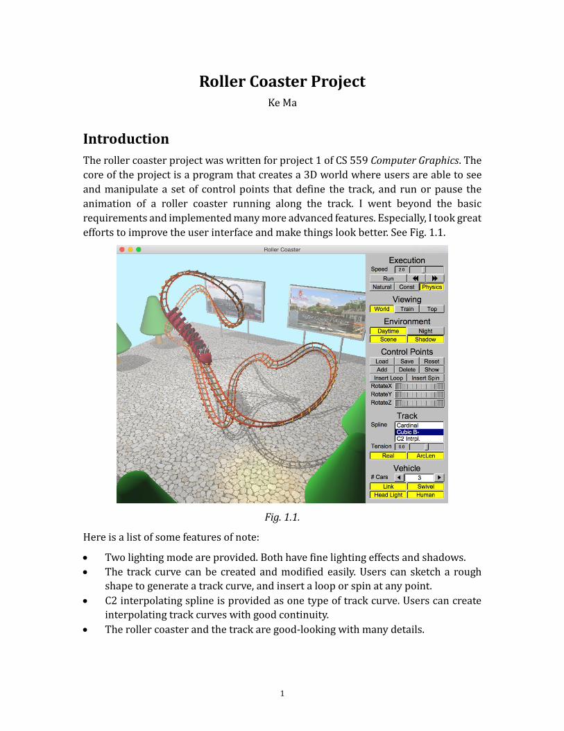
The roller coaster project was written for project 1 of CS 559 Computer Graphics. The
core of the project is a program that creates a 3D world where users are able to see
and manipulate a set of control points that define the track, and run or pause the
animation of a roller coaster running along the track. I went beyond the basic
requirements and implemented many more advanced features. Especially, I took great
efforts to improve the user interface and make things look better. See Fig. 1.1.
Fig. 1.1.
Here is a list of some features of note:
Two lighting mode are provided. Both have fine lighting effects and shadows.
The track curve can be created and modified easily. Users can sketch a rough
shape to generate a track curve, and insert a loop or spin at any point.
C2 interpolating spline is provided as one type of track curve. Users can create
interpolating track curves with good continuity.
The roller coaster and the track are good-looking with many details.
2
Instructions
Compilation and Execution
The full Microsoft Visual Studio 2013 solution folder is provided. It should be able to
be compiled and executed successfully without any modification if the required
libraries (FLTK and GLM) are installed in designated addresses. The source codes and
libraries are cross-platform, which means you can also compile and execute the
program on operating systems other than modern Windows, although you cannot use
the solution directly.
The program has been tested on Windows 7 and Windows 8.1 with Visual Studio 2013,
and on OS X Yosemite with Xcode 6.
The program should be running smoothly on modern computers with OpenGL
support. The performances cannot be promised when running on low-spec
computers.
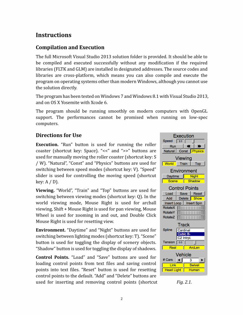
Directions for Use
Execution. “Run” button is used for running the roller
coaster (shortcut key: Space). “<<” and “>>” buttons are
used for manually moving the roller coaster (shortcut key: S
/ W). “Natural”, “Const” and “Physics” buttons are used for
switching between speed modes (shortcut key: V). “Speed”
slider is used for controlling the moving speed (shortcut
key: A / D).
Viewing. “World”, “Train” and “Top” buttons are used for
switching between viewing modes (shortcut key: Q). In the
world viewing mode, Mouse Right is used for arcball
viewing, Shift + Mouse Right is used for pan viewing, Mouse
Wheel is used for zooming in and out, and Double Click
Mouse Right is used for resetting view.
Environment. “Daytime” and “Night” buttons are used for
switching between lighting modes (shortcut key: T). “Scene”
button is used for toggling the display of scenery objects.
“Shadow” button is used for toggling the display of shadows.
Control Points. “Load” and “Save” buttons are used for
loading control points from text files and saving control
points into text files. “Reset” button is used for resetting
control points to the default. “Add” and “Delete” buttons are
used for inserting and removing control points (shortcut Fig. 2.1.
3
key: Insert / Delete). “Show” button is used for toggling the display of control points.
“Insert Loop” and “Insert Spin” buttons are used for inserting loops and spins at
selected control points. In the world and top viewing modes, Mouse Left is used for
moving control points on the horizontal plane, Shift + Mouse Left is used for elevating
control points, and “Rotate X”, “Rotate Y” and “Rotate Z” rollers are used for rotating
control points along three fixed axes. In the top viewing mode, Shift + Mouse Left is
used for sketching rough curves to generate control points.
Track. “Spline” browser is used for switching between spline types (shortcut key: C).
“Tension” slider is used for controlling the tension of Cardinal cubic splines. “Real”
button is used for toggling the display of real tracks with parallel rails and rail ties.
“ArcLen” button is used for toggling the use of arc length parameters for drawing rail
ties.
Vehicle. “# Cars” counter is used for increasing and decreasing the number of cars on
the roller coaster (shortcut key: + / -). “Link” button is used for toggling the display of
links between neighboring cars. “Swivel” button is used for toggling the display of
swiveling roller coaster wheels. “Headlight” button is used for switching on / off
headlights of the roller coaster. “Human” button is used for toggling the display of
people on the first car.

4
Features
Basic
Have a track that is C1, and interpolates the control points. I implemented the
cardinal cubic spline as one type of track. It is of C1 continuity and interpolating. It’s
a closed loop. See Fig. 3.1.
Technical Notes: The program calculates the points on the curve by multiplying the u
vector and the basis matrix to get the blending functions and then using them to blend
the control points. It subdivides the curve into pieces that span 0.02 in u space, and stores
the coordinates of the points in an array. Every time it wants to access a point on the
curve, it looks up the array and linearly interpolates the neighboring points. Only when
the curve is changed (when control points or the spline type are changed), the
interpolation is performed again.
Fig. 3.1. Fig. 3.2.
Have a roller coaster that goes around the track and is oriented correctly on the
track. I didn’t make a train; instead I made a roller coaster! It has an obvious “head”.
It is rigid and always goes along the track with correct orientation. See Fig. 3.2.
Technical Notes: To correctly orient the roller coaster, the program needs to know at least
the tangents of the points on the curve. The tangents are estimated by calculating the
difference between two neighboring subdivision points. They are also stored and
interpolated when used. For more information about orientation in 3D, please see below.
5
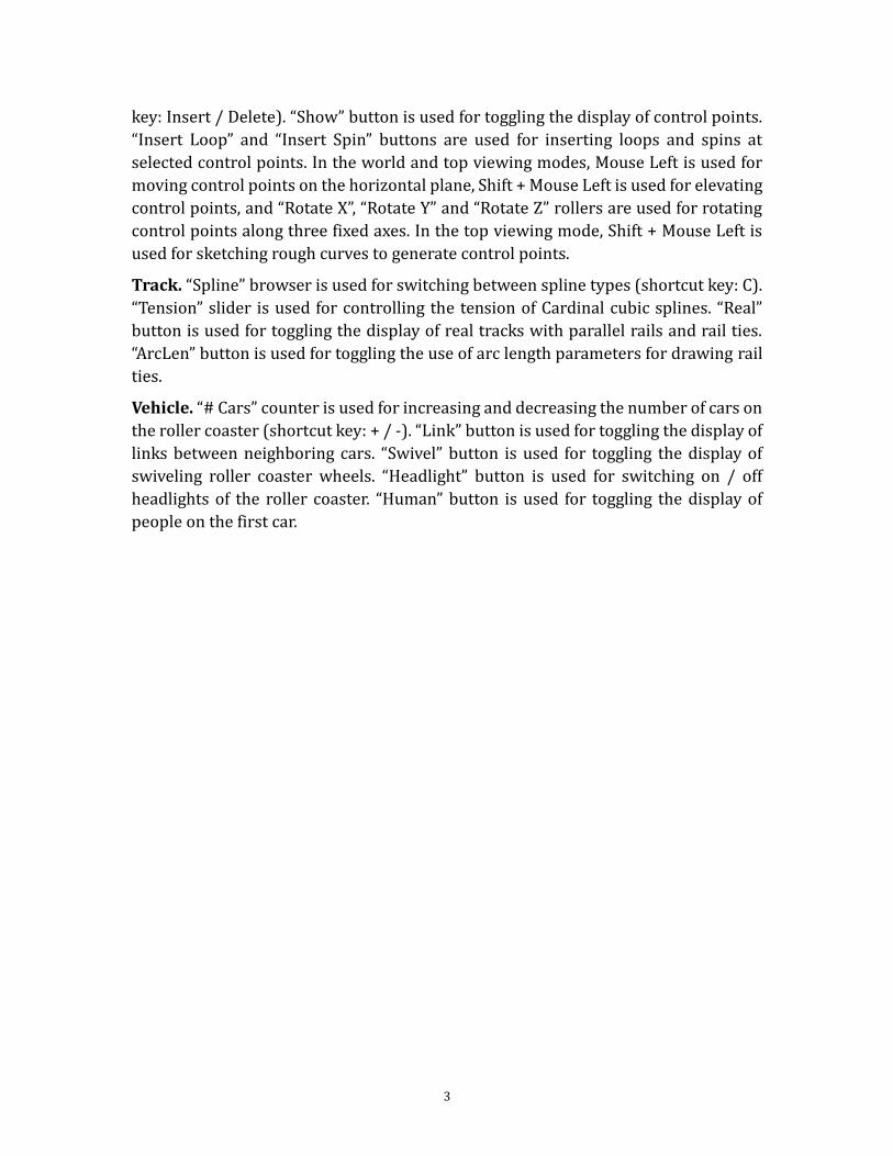
Allow the user to "ride" the roller coaster. I implemented the Train Cam mode. See
Fig. 3.3.
Technical Notes: The program can get the position from the u parameter where the roller
coaster is. This can be the Look From point, but in fact it is translated a little to make the
scene look better. The Look At point is the Look From point plus the tangent vector
(actually the tangent vector is also rotated a little). The Up Vector needs correct 3D
orientation. Please see below.
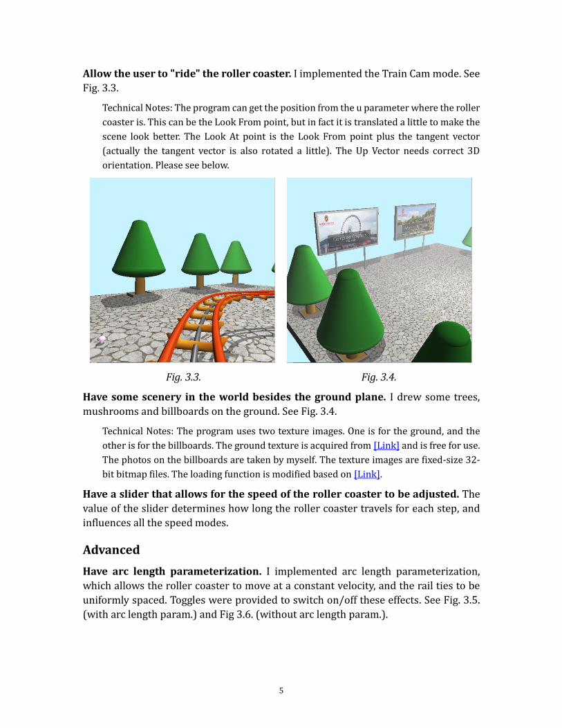
Fig. 3.3. Fig. 3.4.
Have some scenery in the world besides the ground plane. I drew some trees,
mushrooms and billboards on the ground. See Fig. 3.4.
Technical Notes: The program uses two texture images. One is for the ground, and the
other is for the billboards. The ground texture is acquired from [Link] and is free for use.
The photos on the billboards are taken by myself. The texture images are fixed-size 32-
bit bitmap files. The loading function is modified based on [Link].
Have a slider that allows for the speed of the roller coaster to be adjusted. The
value of the slider determines how long the roller coaster travels for each step, and
influences all the speed modes.
Advanced
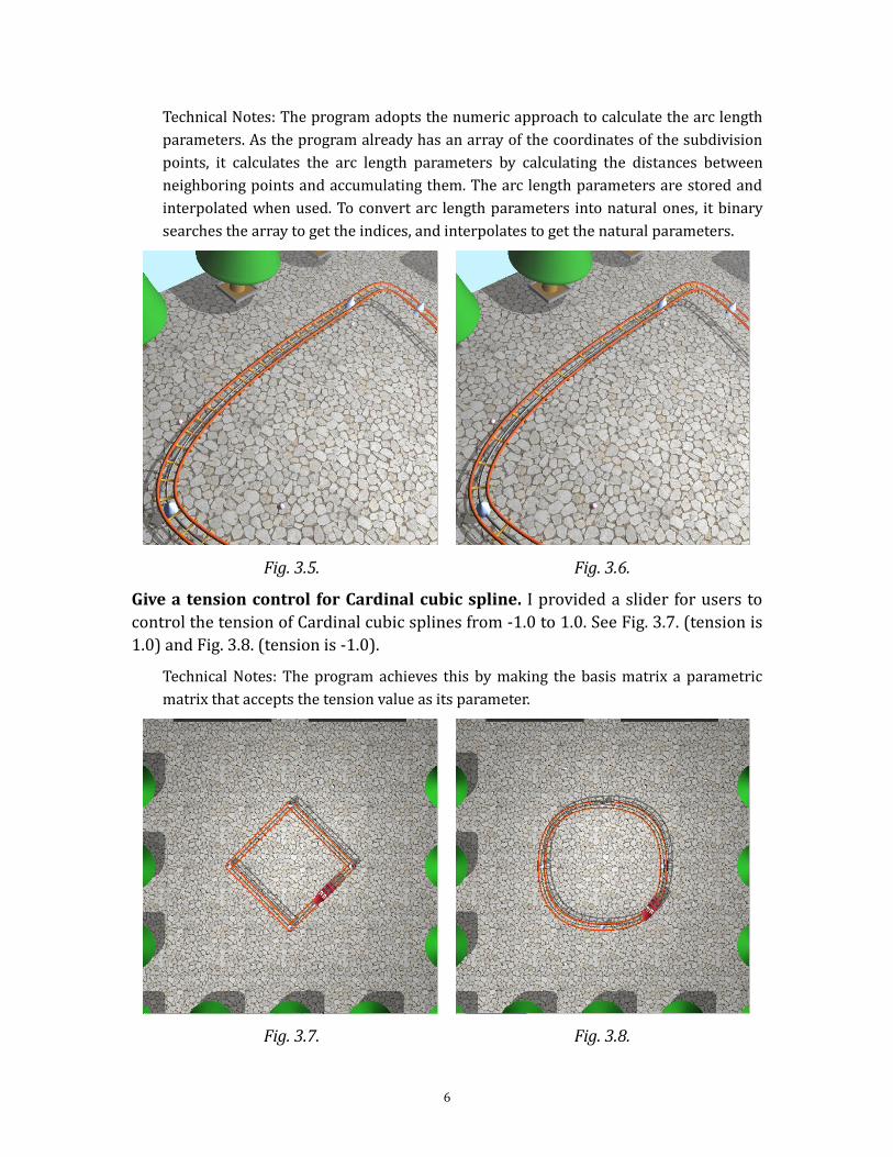
Have arc length parameterization. I implemented arc length parameterization,
which allows the roller coaster to move at a constant velocity, and the rail ties to be
uniformly spaced. Toggles were provided to switch on/off these effects. See Fig. 3.5.
(with arc length param.) and Fig 3.6. (without arc length param.).
6
Technical Notes: The program adopts the numeric approach to calculate the arc length
parameters. As the program already has an array of the coordinates of the subdivision
points, it calculates the arc length parameters by calculating the distances between
neighboring points and accumulating them. The arc length parameters are stored and
interpolated when used. To convert arc length parameters into natural ones, it binary
searches the array to get the indices, and interpolates to get the natural parameters.
Fig. 3.5. Fig. 3.6.
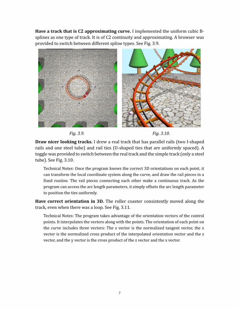
Give a tension control for Cardinal cubic spline. I provided a slider for users to
control the tension of Cardinal cubic splines from -1.0 to 1.0. See Fig. 3.7. (tension is
1.0) and Fig. 3.8. (tension is -1.0).
Technical Notes: The program achieves this by making the basis matrix a parametric
matrix that accepts the tension value as its parameter.
Fig. 3.7. Fig. 3.8.
7
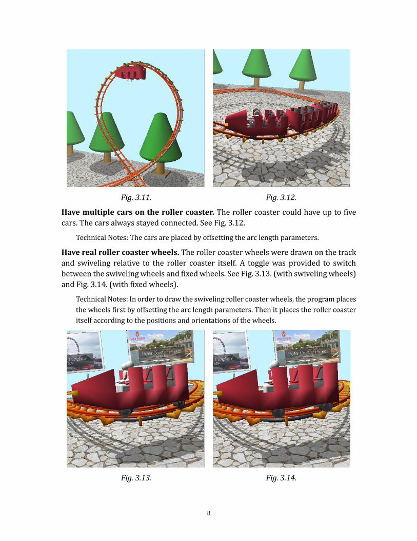
Have a track that is C2 approximating curve. I implemented the uniform cubic B-
splines as one type of track. It is of C2 continuity and approximating. A browser was
provided to switch between different spline types. See Fig. 3.9.
Fig. 3.9. Fig. 3.10.
Draw nicer looking tracks. I drew a real track that has parallel rails (two I-shaped
rails and one steel tube) and rail ties (U-shaped ties that are uniformly spaced). A
toggle was provided to switch between the real track and the simple track (only a steel
tube). See Fig. 3.10.
Technical Notes: Once the program knows the correct 3D orientations on each point, it
can transform the local coordinate system along the curve, and draw the rail pieces in a
fixed routine. The rail pieces connecting each other make a continuous track. As the
program can access the arc length parameters, it simply offsets the arc length parameter
to position the ties uniformly.
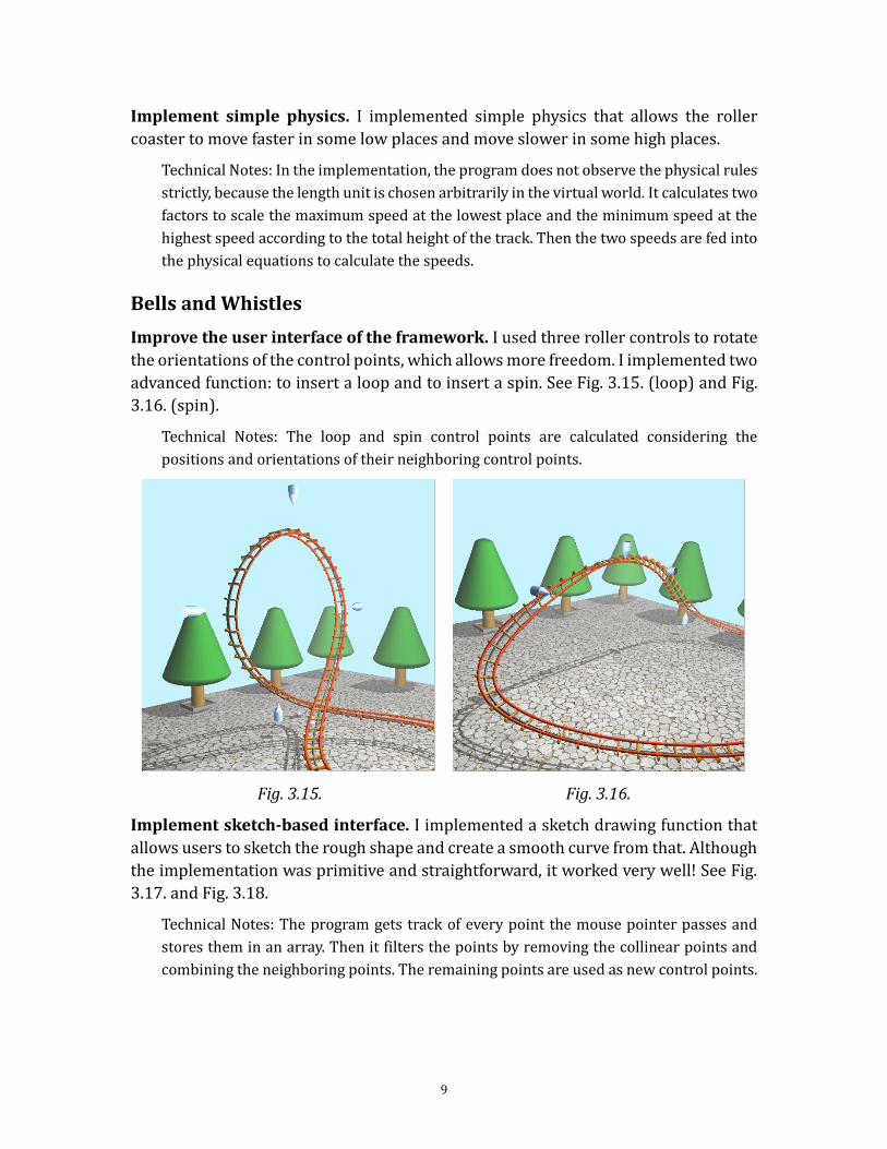
Have correct orientation in 3D. The roller coaster consistently moved along the
track, even when there was a loop. See Fig. 3.11.
Technical Notes: The program takes advantage of the orientation vectors of the control
points. It interpolates the vectors along with the points. The orientation of each point on
the curve includes three vectors: The z vector is the normalized tangent vector, the x
vector is the normalized cross product of the interpolated orientation vector and the z
vector, and the y vector is the cross product of the z vector and the x vector.
8
Fig. 3.11. Fig. 3.12.
Have multiple cars on the roller coaster. The roller coaster could have up to five
cars. The cars always stayed connected. See Fig. 3.12.
Technical Notes: The cars are placed by offsetting the arc length parameters.
Have real roller coaster wheels. The roller coaster wheels were drawn on the track
and swiveling relative to the roller coaster itself. A toggle was provided to switch
between the swiveling wheels and fixed wheels. See Fig. 3.13. (with swiveling wheels)
and Fig. 3.14. (with fixed wheels).
Technical Notes: In order to draw the swiveling roller coaster wheels, the program places
the wheels first by offsetting the arc length parameters. Then it places the roller coaster
itself according to the positions and orientations of the wheels.
Fig. 3.13. Fig. 3.14.
9
Implement simple physics. I implemented simple physics that allows the roller
coaster to move faster in some low places and move slower in some high places.
Technical Notes: In the implementation, the program does not observe the physical rules
strictly, because the length unit is chosen arbitrarily in the virtual world. It calculates two
factors to scale the maximum speed at the lowest place and the minimum speed at the
highest speed according to the total height of the track. Then the two speeds are fed into
the physical equations to calculate the speeds.
Bells and Whistles
Improve the user interface of the framework. I used three roller controls to rotate
the orientations of the control points, which allows more freedom. I implemented two
advanced function: to insert a loop and to insert a spin. See Fig. 3.15. (loop) and Fig.
3.16. (spin).
Technical Notes: The loop and spin control points are calculated considering the
positions and orientations of their neighboring control points.
Fig. 3.15. Fig. 3.16.
Implement sketch-based interface. I implemented a sketch drawing function that
allows users to sketch the rough shape and create a smooth curve from that. Although
the implementation was primitive and straightforward, it worked very well! See Fig.
3.17. and Fig. 3.18.
Technical Notes: The program gets track of every point the mouse pointer passes and
stores them in an array. Then it filters the points by removing the collinear points and
combining the neighboring points. The remaining points are used as new control points.
10
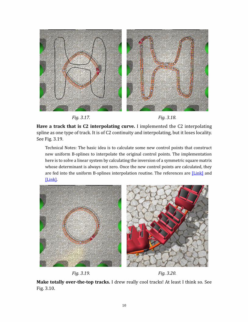
Fig. 3.17. Fig. 3.18.
Have a track that is C2 interpolating curve. I implemented the C2 interpolating
spline as one type of track. It is of C2 continuity and interpolating, but it loses locality.
See Fig. 3.19.
Technical Notes: The basic idea is to calculate some new control points that construct
new uniform B-splines to interpolate the original control points. The implementation
here is to solve a linear system by calculating the inversion of a symmetric square matrix
whose determinant is always not zero. Once the new control points are calculated, they
are fed into the uniform B-splines interpolation routine. The references are [Link] and
[Link].
Fig. 3.19. Fig. 3.20.
Make totally over-the-top tracks. I drew really cool tracks! At least I think so. See
Fig. 3.10.
11
Have different kinds of cars. The first car was drawn differently from the following
cars. Only the first car has a “head” and headlights. See Fig. 3.12.
Have links between cars. I drew links between neighboring cars. The links are
always connecting two cars in right places. See Fig. 3.20.
Technical Notes: The program keeps record of the hook position when drawing every car,
and draws the links accordingly.
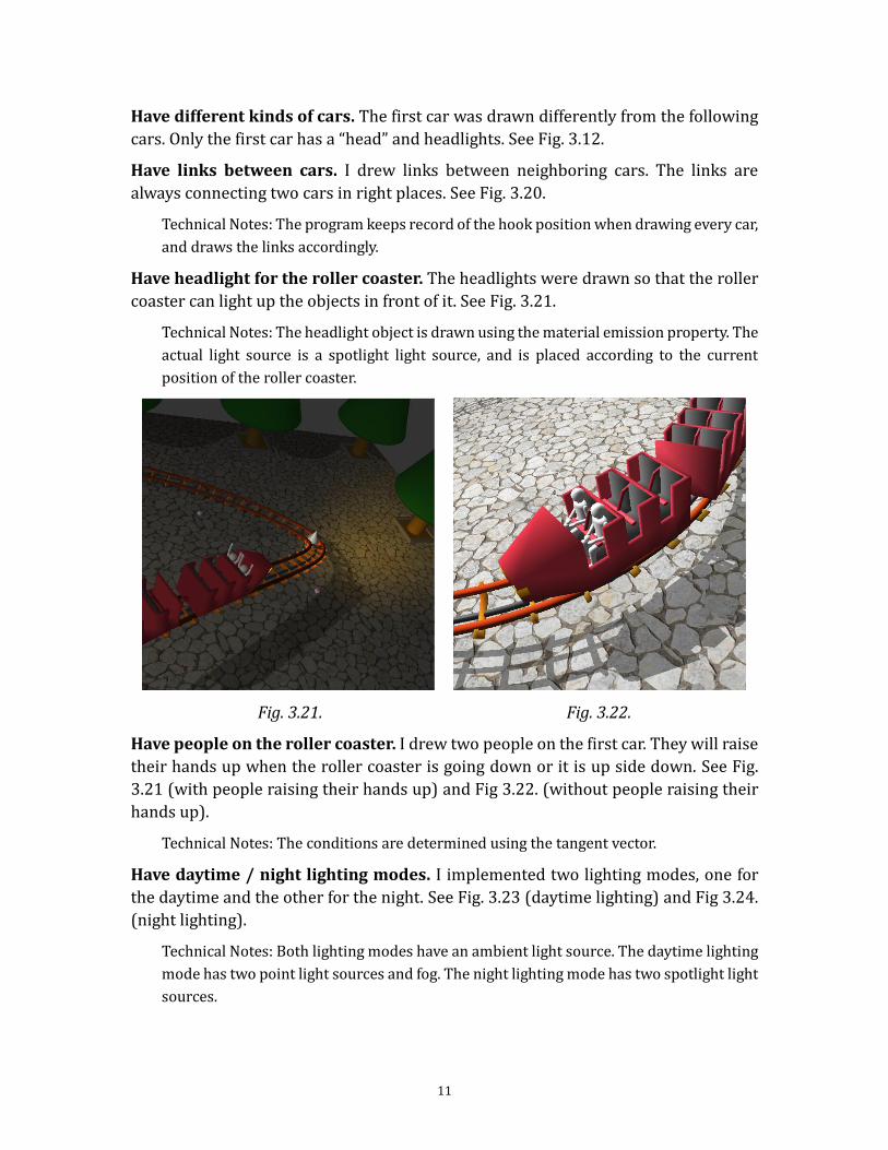
Have headlight for the roller coaster. The headlights were drawn so that the roller
coaster can light up the objects in front of it. See Fig. 3.21.
Technical Notes: The headlight object is drawn using the material emission property. The
actual light source is a spotlight light source, and is placed according to the current
position of the roller coaster.
Fig. 3.21. Fig. 3.22.
Have people on the roller coaster. I drew two people on the first car. They will raise
their hands up when the roller coaster is going down or it is up side down. See Fig.
3.21 (with people raising their hands up) and Fig 3.22. (without people raising their
hands up).
Technical Notes: The conditions are determined using the tangent vector.
Have daytime / night lighting modes. I implemented two lighting modes, one for
the daytime and the other for the night. See Fig. 3.23 (daytime lighting) and Fig 3.24.
(night lighting).
Technical Notes: Both lighting modes have an ambient light source. The daytime lighting
mode has two point light sources and fog. The night lighting mode has two spotlight light
sources.
12
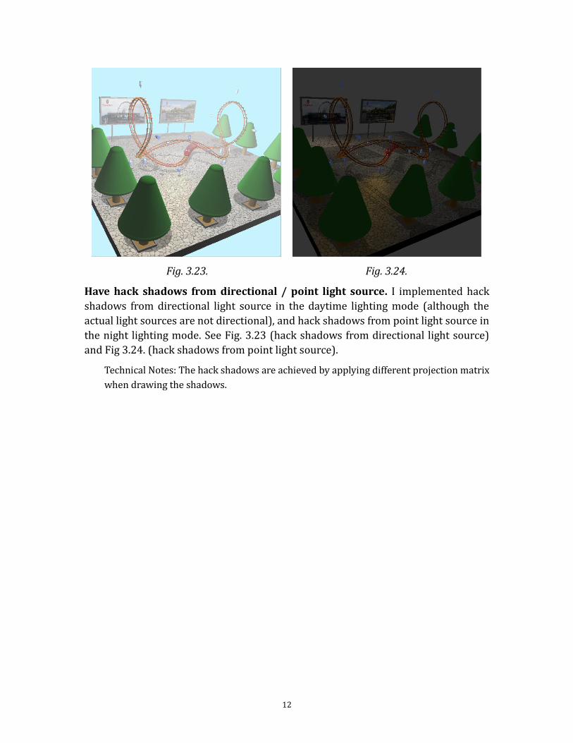
Fig. 3.23. Fig. 3.24.
Have hack shadows from directional / point light source. I implemented hack
shadows from directional light source in the daytime lighting mode (although the
actual light sources are not directional), and hack shadows from point light source in
the night lighting mode. See Fig. 3.23 (hack shadows from directional light source)
and Fig 3.24. (hack shadows from point light source).
Technical Notes: The hack shadows are achieved by applying different projection matrix
when drawing the shadows.