rolled ball screws - drive. · pdf filethread rolling heat treatment: annealing quenching and...
TRANSCRIPT

ROLLED BALL SCREWS –THE ALTERNATIVE IN LINEAR TECHNOLOGY
Steinmeyer Produktbroschüre Gerollte Kugelgewindetriebe EN-2016-05 v.1.15.indd 1 02.05.16 10:00

2
Steinmeyer Produktbroschüre Gerollte Kugelgewindetriebe EN-2016-05 v.1.15.indd 2 02.05.16 10:00

STEINMEYER | ROLLED BALL SCREWS
INDEX
1 Model overview ����������������������������������������������������������������4
Screw shafts ��������������������������������������������������������������������������4
Nuts on mounting sleeves �������������������������������������� 5 – 7
2 Ball screw technology ���������������������������������������������������8
2�1 Manufacturing process ����������������������������������������������������8
2�2 Accuracy classes �����������������������������������������������������������������9
2�2�1 Lead error �������������������������������������������������������������������������������9
2�2�2 Shape and position tolerances �������������������10 – 12
2�3 Bearing journals
and bearing recommendations ������������������������� 13
2�3�1 Bearing selection ������������������������������������������������ 14
2�3�2 Commonly used bearings ���������������������������������� 15
2�3�3 Bearing journals - standard machining�����16 – 17
2�4 Ball return ���������������������������������������������������������������������������� 18
2�4�1 Multiliner (internal return) ��������������������������������� 18
2�4�2 Technical tip �������������������������������������������������������� 18
2�4�3 Through-the-nut return (external return) �������� 19
2�4�4 End cap return (external return) ����������������������� 19
2�5 Rotation speed values ���������������������������������������������������� 20
2�5�1 Critical speed ���������������������������������������������������������������������� 20
2�5�2 Maximum speed ���������������������������������������������������������������� 20
2�5�3 DN value �������������������������������������������������������������������������������� 20
2�6 Nut clearance ��������������������������������������������������������������������� 21
2�7 Maximum loads ������������������������������������������� 22 – 23
2�8 Wipers ������������������������������������������������������������������������������������ 24
2�9 Lubrication , installation and assembly ��������������� 24
2�9�1 Handling �������������������������������������������������������������� 24
2�9�2 Storage ���������������������������������������������������������������� 24
2�9�3 Cleaning ��������������������������������������������������������������������������������� 24
2�9�4 Nut assembly ���������������������������������������������������������������������� 25
2�9�5 Installation ��������������������������������������������������������������������������� 26
2�9�6 Lubrication ��������������������������������������������������������������������������� 27
3 Ordering information �������������������������������������������������� 28
3�1 Order code ���������������������������������������������������������������������������� 28
3�2 Availability ���������������������������������������������������������������������������� 29
4 Products ���������������������������������������������������������������������������30
4�1 Flange nuts on mounting sleeves ������������������30 – 33
4�2 Nuts with connecting thread
on mounting sleeves ���������������������������������������������34 – 35
4�3 Screw shafts �������������������������������������������������������������36 – 37
5 Selection guide ��������������������������������������������������������������38
5�1 Service life�����������������������������������������������������������38
5�1�1 Load capacity selection ������������������������������������������������� 38
5�1�2 Dynamic axial load capacity �����������������������������38 – 39
5�2 Static axial load capacity ����������������������������������������������40
5�3 Radial loads �������������������������������������������������������������������������40
5�4 Stiffness ��������������������������������������������������������������������������������40
5�5 Critical column load ���������������������������������������������������������41
5�6 Critical speeds ��������������������������������������������������������������������41
3
Steinmeyer Produktbroschüre Gerollte Kugelgewindetriebe EN-2016-05 v.1.15.indd 3 02.05.16 10:00
1 | MODEL OVERVIEW
SCREW SHAFTS
16
20
25
32
40
50
63
80
Diameter in mm
3 m*
3 m*
6 m*
Lead
2 m
m
3 m*
3 m*
Lead
2,5
mm
3 m*
3 m*
Lead
4 m
m
3 m
3 m
6 m
6 m
6 m
Lead
5 m
m
6 m*
6 m*
Lead
8 m
m
3 m
3 m
6 m
6 m
6 m
6 m
6 m
6 m
Lead
10
mm
6 m*
6 m*
6 m*
6 m*
Lead
15
mm
3 m
6 m
6 m
6 m
6 m
6 m
6 m*
Lead
20
mm
6 m
Lead
25
mm
6 m
Lead
32
mm
3 m*
6 m
Lead
40
mm
6 m*
Lead
50
mm
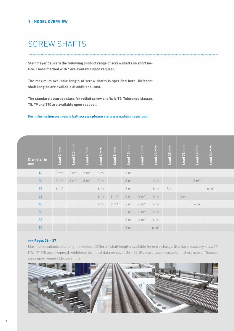
Steinmeyer delivers the following product range of screw shafts on short no-
tice. Those marked with * are available upon request.
The maximum available length of screw shafts is specified here. Different
shaft lengths are available at additional cost.
The standard accuracy class for rolled screw shafts is T7. Tolerance classes
T5, T9 and T10 are available upon request.
For information on ground ball screws please visit: www.steinmeyer.com
>>> Pages 36 – 37
Maximum available total length in meters� Different shaft lengths available for extra charge� Standard accuracy class T7
(T5, T9, T10 upon request)� Additional technical data on pages 36 – 37� Standard sizes available on short notice� *Special
sizes upon request (delivery time)�
4
Steinmeyer Produktbroschüre Gerollte Kugelgewindetriebe EN-2016-05 v.1.15.indd 4 02.05.16 10:00
1 | MODEL OVERVIEW
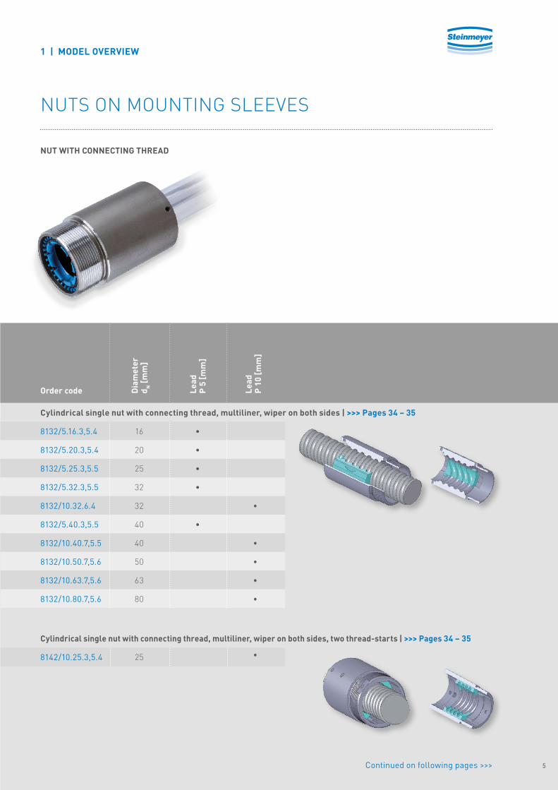
NUTS ON MOUNTING SLEEVES
NUT WITH CONNECTING THREAD
8132/5.16.3,5.4
8132/5.20.3,5.4
8132/5.25.3,5.5
8132/5.32.3,5.5
8132/10.32.6.4
8132/5.40.3,5.5
8132/10.40.7,5.5
8132/10.50.7,5.6
8132/10.63.7,5.6
8132/10.80.7,5.6
8142/10.25.3,5.4
Cylindrical single nut with connecting thread, multiliner, wiper on both sides | >>> Pages 34 – 35
Cylindrical single nut with connecting thread, multiliner, wiper on both sides, two thread-starts | >>> Pages 34 – 35
Order code
25
16
20
25
32
32
40
40
50
63
80
Dia
met
erd N
[mm
]
•
•
•
•
•
Lead
P 5
[mm
]
•
•
•
•
•
•
Lead
P 10
[mm
]
Continued on following pages >>> 5
Steinmeyer Produktbroschüre Gerollte Kugelgewindetriebe EN-2016-05 v.1.15.indd 5 02.05.16 10:00

1 | MODEL OVERVIEW
NUTS ON MOUNTING SLEEVES
FLANGE NUT
8436/5.16.3,5.3
8436/5.20.3,5.3
8436/5.25.3,5.3
8436/5.32.3,5.4
8436/10.32.6.3
8436/5.40.3,5.5
8436/10.40.7,5.4
8436/10.50.7,5.4
8436/10.63.7.5.5
8436/10.80.7,5.6
8446/20.50.7,5.6
Flange single nut, multiliner, wiper on both sides | >>> Pages 30 – 33
Flange single nut, multiliner, wiper on both sides, two thread-starts | >>> Pages 30 – 33
Order code
16
20
25
32
32
40
40
50
63
80
50
Dia
met
erd N
[mm
]
•
•
•
•
•
Lead
P 5
[mm
]
Lead
P 10
[mm
]
Lead
P 20
[mm
]
•
•
•
•
•
•
6
Steinmeyer Produktbroschüre Gerollte Kugelgewindetriebe EN-2016-05 v.1.15.indd 6 02.05.16 10:00

2446/10.16.3,5.6
2446/10.20.3,5.6
2446/20.20.3,5.4
2446/10.25.3,5.6
2446/20.25.3,5.4
2446/25.25.3,5.4
3446/20.32.6.4
3446/32.32.6.2
3446/20.40.6.6
3446/40.40.7,5.4
3446/20.63.7,5.6
Flange single nut, end cap return, wiper on both sides, two thread-starts | >>> Pages 30 – 33
Flange single nut, external through-the-nut return , wiper on both sides, two thread-starts | >>> Pages 30 – 33
Order code Dia
met
erd N
[mm
]
16
20
20
25
25
25
32
32
40
40
63
Lead
P 10
[mm
]
•
•
•
Lead
P 20
[mm
]
•
•
•
•
•
Lead
P 25
[mm
]
•
Lead
P 40
[mm
]
•
Lead
P 32
[mm
]
•
1 | MODEL OVERVIEW
NUTS ON MOUNTING SLEEVES
FLANGE NUT
7
Steinmeyer Produktbroschüre Gerollte Kugelgewindetriebe EN-2016-05 v.1.15.indd 7 02.05.16 10:00

2 | BALL SCREW TECHNOLOGY
2�1 | MANUFACTURING PROCESS
Thread rolling
Heat treatment: annealing ��� and temperingQuenching ���
Alignment Polishing Measuring
8
Steinmeyer Produktbroschüre Gerollte Kugelgewindetriebe EN-2016-05 v.1.15.indd 8 02.05.16 10:00
Deviation
Travel
Iu
+ep
-ep
e 0a
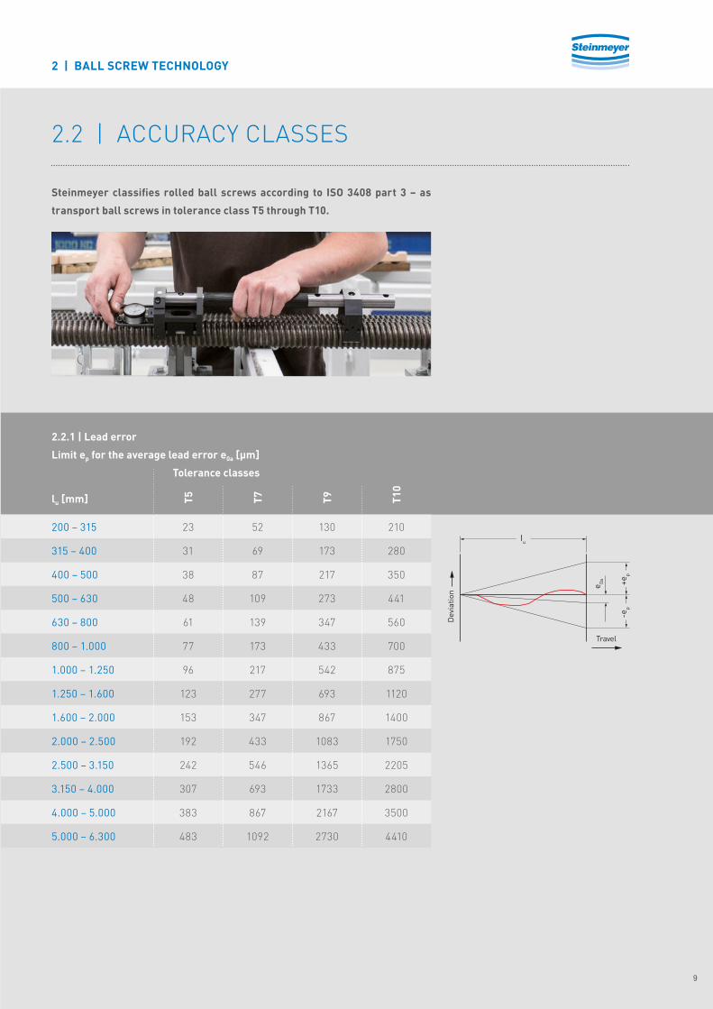
2�2 | ACCURACY CLASSES
Steinmeyer classifies rolled ball screws according to ISO 3408 part 3 – as
transport ball screws in tolerance class T5 through T10.
2 | BALL SCREW TECHNOLOGY
200 – 315
315 – 400
400 – 500
500 – 630
630 – 800
800 – 1.000
1.000 – 1.250
1.250 – 1.600
1.600 – 2.000
2.000 – 2.500
2.500 – 3.150
3.150 – 4.000
4.000 – 5.000
5.000 – 6.300
2.2.1 | Lead error
Limit ep for the average lead error e0a [µm]
lu [mm]
Tolerance classes
T5
23
31
38
48
61
77
96
123
153
192
242
307
383
483
T7
52
69
87
109
139
173
217
277
347
433
546
693
867
1092
T9
130
173
217
273
347
433
542
693
867
1083
1365
1733
2167
2730
T10
210
280
350
441
560
700
875
1120
1400
1750
2205
2800
3500
4410
9
Steinmeyer Produktbroschüre Gerollte Kugelgewindetriebe EN-2016-05 v.1.15.indd 9 02.05.16 10:00

B
A
C
Y1 Y6 A - A'
C
A - A' D - D' Y4
A'
Y3
D
Y1 A - A'
Y3 D - D' Y5
C
B
Y2
D'
L1
2d0 2d0L6
2d0L7
2d0
d0
2 | BALL SCREW TECHNOLOGY
2.2.2 | Shape and position tolerances
The following values define the shape and position tolerances of the functional
surfaces of the ball screws. They are specifically applicable when no other
specifications are provided. Measurement using Vee-block supports at the
outside diameter of the shaft at points A and A’ and D and D’.
16 - 20
25 - 50
63 - 80
16 - 20
25 - 50
63 - 80
80
125
200
80
125
200
20
25
32
8
10
12
40
50
63
12
16
20
63
80
100
16
20
25
63
80
100
16
20
25
Bearing journal concentric run-out Y1 [µm]
Drive journal concentric run-out Y2 [µm]
Nom
inal
-ø[m
m]
Nom
inal
-ø[m
m]
L [m
m]
T5 T7 T9 T10
Measurement E 6�1 according to ISO 3408 for journal length L6 ≦ L� The following applies for L6 > L: tolerance value *L6/L
Measurement E 6�1 according to ISO 3408 for pin length L7 ≦ L� The following applies for L7 > L: tolerance value *L7/L
L [m
m]
T5 T7 T9 T10
10
Steinmeyer Produktbroschüre Gerollte Kugelgewindetriebe EN-2016-05 v.1.15.indd 10 02.05.16 10:00

16
20 - 40
50 - 80
16 - 25
32 - 63
80
16
20
25
20
25
32
20
25
32
25
32
40
-
-
-
-
-
-
-
-
-
-
-
-
Nut concentric run-out Y4 [µm]
Concentric run-out of nut flange and shaft OD Y5 [µm]
Nom
inal
-ø[m
m]
Nom
inal
-ø[m
m]
T5 T7 T9 T10
The values specified have been converted and correspond with the specifications of ISO 3408�
The values specified have been converted and correspond with the specifications of ISO 3408�
T5 T7 T9 T10
16 - 63
80
5
6
6
5
10
12
10
12
Bearing journal axial run-out Y3 [µm]
Nom
inal
-ø[m
m]
T5 T7 T9 T10
The values specified have been converted and correspond with the specifications of ISO 3408�
2 | BALL SCREW TECHNOLOGY
11
Steinmeyer Produktbroschüre Gerollte Kugelgewindetriebe EN-2016-05 v.1.15.indd 11 02.05.16 10:00

2 | BALL SCREW TECHNOLOGY
Concentric run-out of shaft exterior diameter Y6 for short shafts [µm]
Concentric run-out of shaft exterior diameter Y6 for long shafts [µm]
16 - 25
32 - 50
63 - 80
Nom
inal
-ø[m
m]
16 - 25
32 - 50
63 - 80
Nom
inal
-ø[m
m]
The measuring interval should be chosen according to the chart�
(Thread length ≦ 4* Measuring interval)
The measuring interval should be chosen according to the chart�
(Thread length >4* Measuring interval)
< 640
< 1260
< 2520
Leng
th o
f th
read
L1 [m
m]
> 640
> 1260
> 2520
Leng
th o
f th
read
L1 [m
m]
160
315
630
Mea
suri
ngin
terv
al[m
m]
160
315
630
Mea
suri
ngin
terv
al[m
m]
32
32
32T5
64
64
64
T5
40
40
40
T7
80
80
80
T7
80
80
80
T10
160
160
160T1
0
80
80
80
T9
160
160
160
T9
12
Steinmeyer Produktbroschüre Gerollte Kugelgewindetriebe EN-2016-05 v.1.15.indd 12 02.05.16 10:00

Fig. 1
Fig. 2
The mounting should allow for rotation
of the shaft and simultaneously pass
the axial force on the ball screw
into the adjacent construction with
as little deformation as possible.
Modern ball screw drives have
very high load bearing capacity and
stiffness, such that only high-quality
bearings that are optimized for drive
screw mounting can adequately meet
requirements. An attachment to the
shaft that is adequate for the axial and
prestressing force of this bearing is of
crucial importance.
Fig� 1: The most simple and cost-
effective option consists of a bearing
journal that is sufficiently small
compared to the nominal diameter of
the shaft� Ideally, the shoulder surface
underneath the minor diameter of the
shaft can sufficiently absorb the force
without deformation�
Fig� 2: If the full shoulder is not
sufficient, a shrunk-on ring with an
exterior diameter larger than the shaft
diameter is necessary�
2�3 | BEARING JOURNALS AND BEARING RECOMMENDATIONS
2 | BALL SCREW TECHNOLOGY
13
Steinmeyer Produktbroschüre Gerollte Kugelgewindetriebe EN-2016-05 v.1.15.indd 13 02.05.16 10:00
2 | BALL SCREW TECHNOLOGY
2.3.1 | Bearing selection
The support bearing of a ball screw
should be able to absorb the axial
force produced by the nut and the
lateral forces from the belt drive� It
can sometimes be difficult to find a
suitable bearing for ball screws with
large cycle criteria, and high load
rating� At the same time, the bearing
should have a sufficiently small inner
ring bore hole and a supporting
diameter no larger than the shaft
nominal diameter�
This discussion thus only represents
an initial point of reference for
selection of bearings� It is by no means
meant to be universally applicable or
complete� The following criteria apply
to the selection of a bearing:
• Axial dynamic load rating roughly
equivalent to the dynamic load
rating of the ball nut�
• Support shoulder for the bearing
inner ring no larger than the minor
diameter of the shaft for journal
version fig� 1 (see page 13)�
• The bearing should also be
compatible with the same
lubrication method (oil/grease) and
the same speed as the ball screw�
�
14
Steinmeyer Produktbroschüre Gerollte Kugelgewindetriebe EN-2016-05 v.1.15.indd 14 02.05.16 10:00

Steinmeyer recommends installing INA
(angular) ball bearings� The following chart
is an overview of commonly used bearings�
Since it is not possible to display all
combinations here, we ask that you consult
with us for your special applications�
INA mounting selection for fixed bearings
Bearing selection for loose bearings
16
20
25
32 (P=5)
32 (P≧10)
40 (P=5)
40 (P≧10)
50
63
80
16
20
25
32 (P=5)
32 (P≧10)
40 (P=5)
40 (P≧10)
50
63
80
6200
6201
6203
6204
6204
6206
6206
6207
6210
6212
10x1
12x1
17x1
20x1,2
20x1,2
30x1,5
30x1,5
35x1,5
50x1,5
60x2
Ball screw driveNominal-ø [mm]
Ball screw driveNominal-ø [mm]
ZKLN1034
ZKLN1242
ZKLN1747
ZKLN2557
ZKLN2052
ZKLN3062
ZKLN2557-2AP
ZKLN3572-2AP
ZKLN4075-2AP
ZARN5090-TV
According to chapter 2.3 (page 13) fig. 1(complimentary to standard machiningA described in chapter 2.3.3)
Loose bearing(complimentary to standard machiningB described in chapter 2.3.3)
Locking ringAccording to DIN 471
According to chapter 2.3 (page 13)Fig. 2
ZKLN1242
ZKLN1545
ZKLN2052
-
ZKLN2557-2AP
-
ZKLN3062-2AP
ZKLN4075-2AP
ZKLN5090-2AP
ZARN50110-TV
2.3.2 | Commonly used bearings
2 | BALL SCREW TECHNOLOGY
15
Steinmeyer Produktbroschüre Gerollte Kugelgewindetriebe EN-2016-05 v.1.15.indd 15 02.05.16 10:00
sw
t
SW
b x l x t
MZ
t Z
Recess shape E DIN509
Recess shape F DIN509Thread recess DIN76 short
Z L
2 L
D 2
G 1
D 1
G1 L L 1
16
20
25
32
32
40
40
50
63
80
d 0
5/10
5/10/20
5/10/20/25
10/20/32
5
10/20/40
5
10/20
10/20
10
P
50
60
75
78
80
130
101
144
154
160
L z
10
12
17
20
25
25
30
35
40
50
D1h6
18
23
23
26
25
54
25
66
66
58
L 1
8
10
15
16
22
22
25
30
36
40
D2 h7
20
25
30
35
40
50
50
50
60
70
L 2
M10x1
M12x1
M17x1
M20x1
M25x1�5
M25x1�5
M30x1�5
M35x1�5
M40x1�5
M50x1�5
G 1
12
12
22
17
15
26
26
28
28
32
LG1
M5
M5
M5
M8
M10
M10
M12
M16
MZ
12
12
12
19
22
22
28
36
t Z
4
4
4
4
4
6
8
10
12
12
SW
5
5
5
5
5
8
10
12
12
12
t SW
2 | BALL SCREW TECHNOLOGY
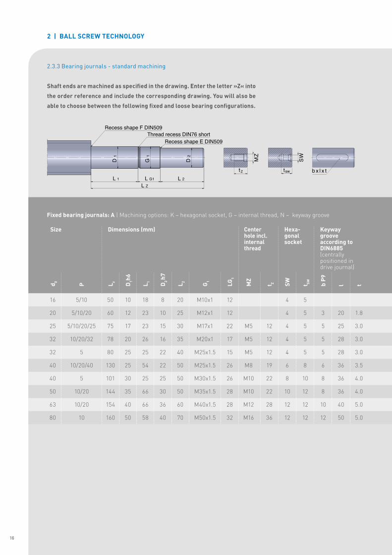
2.3.3 Bearing journals - standard machining
Shaft ends are machined as specified in the drawing. Enter the letter »Z« into
the order reference and include the corresponding drawing. You will also be
able to choose between the following fixed and loose bearing configurations.
Fixed bearing journals: A | Machining options: K – hexagonal socket, G – internal thread, N – keyway groove
3
5
5
5
6
8
8
10
12
b P9
20
25
28
28
36
36
36
40
50
l
1�8
3�0
3�0
3�0
3�5
4�0
4�0
5�0
5�0
t
Keyway groove according to DIN6885 (centrally positioned in drive journal)
Size Dimensions (mm) Centerhole incl. internal thread
Hexa-gonal socket
16
Steinmeyer Produktbroschüre Gerollte Kugelgewindetriebe EN-2016-05 v.1.15.indd 16 02.05.16 10:00
sw
t S
W
b x l x t
MZ
t Z sw
t
SW
b x l x t
MZ
t Z
Recess shape E DIN509Cut-in for retaining ring DIN471
4
m
1 D
L
d2
L Z
2 | BALL SCREW TECHNOLOGY
16
20
25
32
40
50
63
80
d 0
5/10
5/10/20
5/10/20/25
5/10/20/32
5/10/20/40
10/20
10/20
10
P
12
13
15
18
20
22
27
29
L Z
10
12
17
20
30
35
50
60
D1 h6
9
10
12
14
16
17
20
22
L 4
9�6
11�5
16�2
19�0
28�6
33�0
47�0
57�0
d 2
h10
h11
h11
h11
h12
h12
h12
h12
d 2 To
lera
nce
1�10
1�10
1�10
1�30
1�60
1�60
2�15
2�15
m H
13
M4
M6
M6
M10
M12
M16
M20
MZ
10
16
16
22
28
36
42
t z
4
4
5
5
10
12
17
17
SW
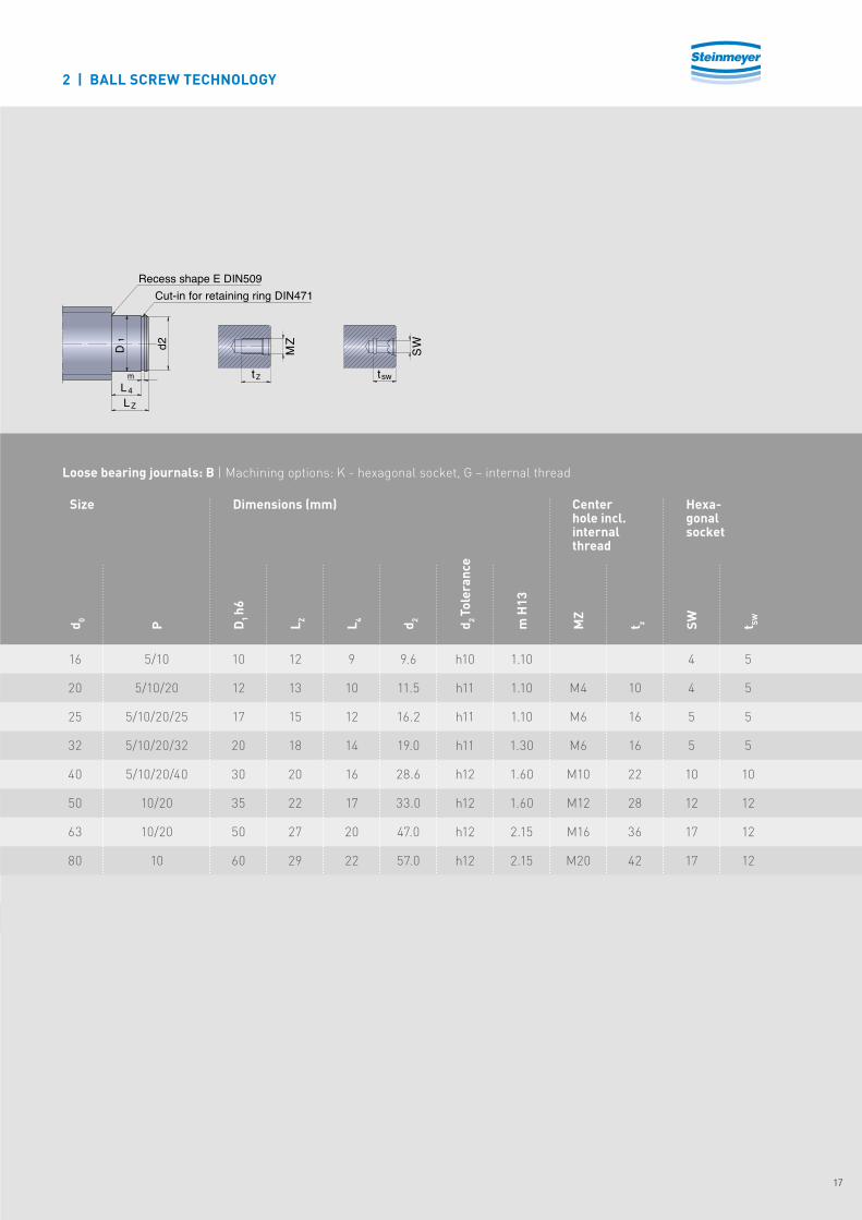
Size Dimensions (mm) Center hole incl. internal thread
Hexa-gonal socket
t SW
5
5
5
5
10
12
12
12
Loose bearing journals: B | Machining options: K - hexagonal socket, G – internal thread
17
Steinmeyer Produktbroschüre Gerollte Kugelgewindetriebe EN-2016-05 v.1.15.indd 17 02.05.16 10:00

2 | BALL SCREW TECHNOLOGY
2�4 | BALL RETURN
As the world‘s only manufacturer never to use tubes, Steinmeyer uses all
commonly known other designs for ball returns. However, the multiliner
return represents the standard for all rolled ball screws. Steinmeyer also
uses external return either as through-the-nut or end cap return.
Ball nuts require a means to recirculate
balls� Without it, the ball circuit would
not be closed and balls would fall out at
the rear end of the nut�
Design of the ball return is the deter-
mining factor for the maximum speed
at which the ball nut can safely operate�
This is normally expressed by the DN
value� The better the ball return system
deals with mass forces of the balls, the
higher the DN value� Manufacturers
typically quote DN values from 60�000
for basic tube returns to 160�000 and
higher, e�g� the UltraSpeed return from
Steinmeyer�
2.4.1 | Multiliner (internal return)
2.4.2 | Technical tip:
Multiliners lift the balls out of the
track and guide them over the outer
diameter of the shaft into the next
available track�
This type of internal return is particu-
larly compact and yields the smallest
nut diameters of any ball return system�
It is also the ball return of choice for
very small ball sizes and small leads�
18
Steinmeyer Produktbroschüre Gerollte Kugelgewindetriebe EN-2016-05 v.1.15.indd 18 02.05.16 10:00
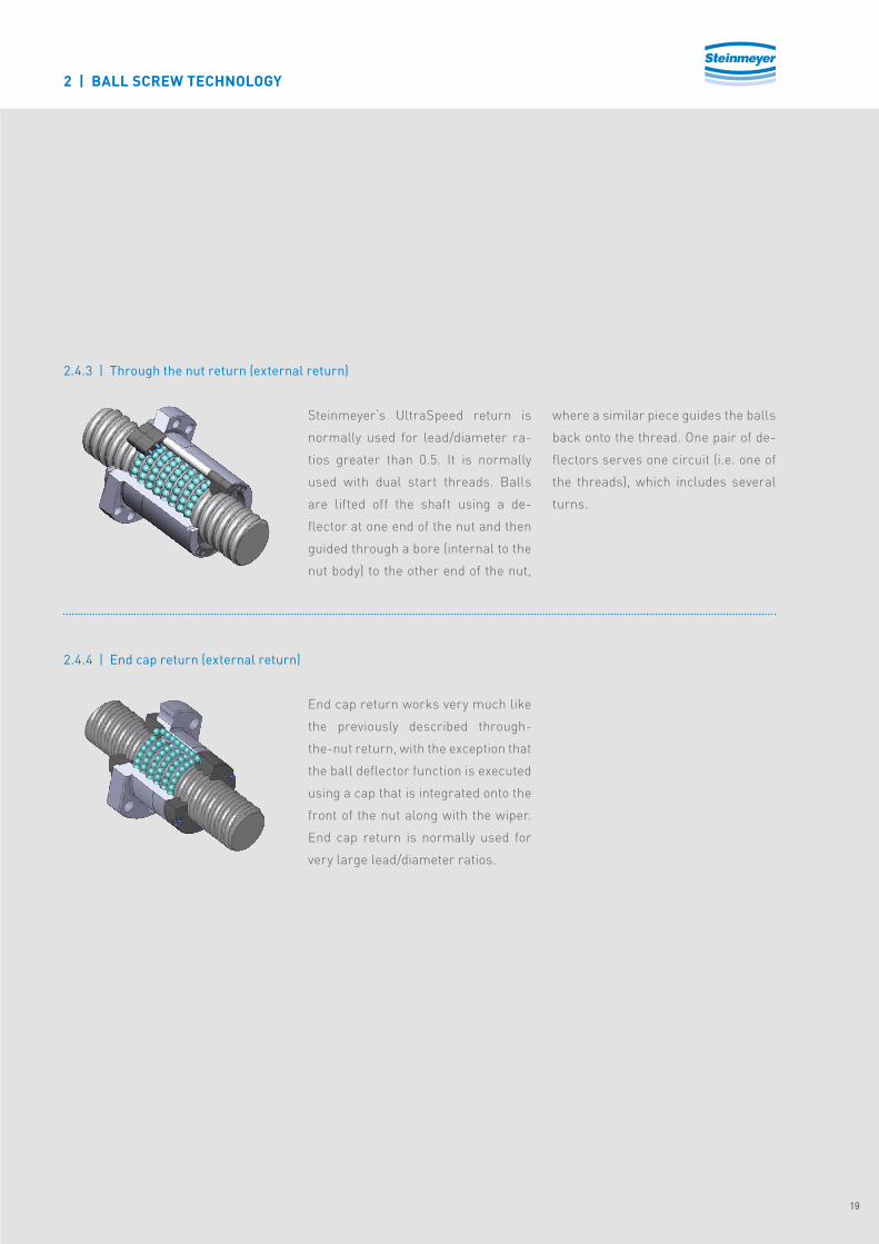
2.4.3 | Through the nut return (external return)
2.4.4 | End cap return (external return)
Steinmeyer‘s UltraSpeed return is
normally used for lead/diameter ra-
tios greater than 0�5� It is normally
used with dual start threads� Balls
are lifted off the shaft using a de-
flector at one end of the nut and then
guided through a bore (internal to the
nut body) to the other end of the nut,
where a similar piece guides the balls
back onto the thread� One pair of de-
flectors serves one circuit (i�e� one of
the threads), which includes several
turns�
End cap return works very much like
the previously described through-
the-nut return, with the exception that
the ball deflector function is executed
using a cap that is integrated onto the
front of the nut along with the wiper�
End cap return is normally used for
very large lead/diameter ratios�
2 | BALL SCREW TECHNOLOGY
19
Steinmeyer Produktbroschüre Gerollte Kugelgewindetriebe EN-2016-05 v.1.15.indd 19 02.05.16 10:00

2 | BALL SCREW TECHNOLOGY
2�5 | ROTATION SPEED VALUES
2.5.1 | Critical speed
Critical speed is the first (lowest)
speed at which the ball screw shaft
is in resonance� In applications with
rotating shafts it limits the rpm of the
screw� Variables that influence it are
shaft diameter, unsupported length
and support bearing configuration�
Detailed calculations can be perfor-
med upon request�
2.5.2 | Maximum speed
A second limitation is imposed by the
mass forces upon balls� It depends on
internal construction of the ball nut
and in particular the ball return, and
ball diameter (or mass)�
2.5.3 | DN Value
DN values allow easy comparison
between different ball screw designs�
More sophisticated ball return sys-
tems result in higher DN values and,
conversely, lower DN values are as-
sociated with less sophisticated ball
return methods� DN values provide
direct correlation to ball velocity�
DN = nmax · dN
nmax = Maximum speed [rpm]
dN = Nominal diameter [mm]
DN = Rotation speed value
The ball screw drives available to-
day have possible DN values of up
to 160,000� However, Steinmeyer re-
commends observing the maximum
speeds published here for each size�
Use the following values for orientati-
on purposes and of course for Stein-
meyer ball screws only�
n Internal return
(Series 8xxx): DN ≦ 80�000
n External return
(UltraSpeed and end-cap return)
(Series 2xxx und 3xxx):
DN ≦ 160�000
20
Steinmeyer Produktbroschüre Gerollte Kugelgewindetriebe EN-2016-05 v.1.15.indd 20 02.05.16 10:00

2�6 | NUT CLEARANCE
Single nut with backlash
Steinmeyer produces rolled ball
screws with a single nut with clea-
rance� This axial clearance amounts
to approx� 0�01 mm with a maximum
0�06 mm for the sizes displayed here�
Versions that are free of clearance/
pre-tensioned are available upon re-
quest� In this instance the nut is not
available separately, but is supplied
already mounted to the screw shaft�
n Axial clearance (approx� 0�01 –
0�06 mm)
n Contact point change with chang-
es in load direction
n always two-point contact
n Balls carry load alternately in
both directions
2 | BALL SCREW TECHNOLOGY
21
Steinmeyer Produktbroschüre Gerollte Kugelgewindetriebe EN-2016-05 v.1.15.indd 21 02.05.16 10:00
2 | BALL SCREW TECHNOLOGY
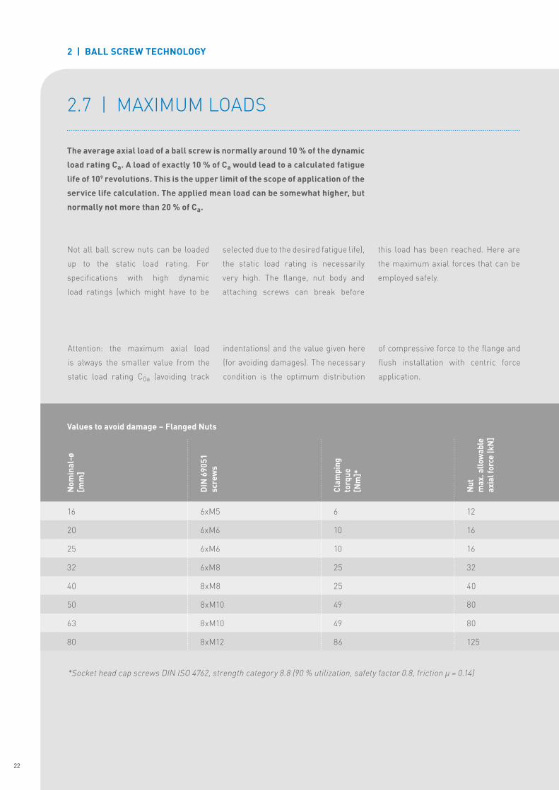
Not all ball screw nuts can be loaded
up to the static load rating� For
specifications with high dynamic
load ratings (which might have to be
selected due to the desired fatigue life),
the static load rating is necessarily
very high� The flange, nut body and
attaching screws can break before
this load has been reached� Here are
the maximum axial forces that can be
employed safely�
Attention: the maximum axial load
is always the smaller value from the
static load rating C0a (avoiding track
indentations) and the value given here
(for avoiding damages)� The necessary
condition is the optimum distribution
of compressive force to the flange and
flush installation with centric force
application�
16
20
25
32
40
50
63
80
Nom
inal
-ø
[mm
]
6xM5
6xM6
6xM6
6xM8
8xM8
8xM10
8xM10
8xM12
DIN
690
51sc
rew
s
6
10
10
25
25
49
49
86
Clam
ping
to
rque
[Nm
]*
12
16
16
32
40
80
80
125
Nut
max
. allo
wab
le
axia
l for
ce |k
N]
2�7 | MAXIMUM LOADS
The average axial load of a ball screw is normally around 10 % of the dynamic
load rating Ca. A load of exactly 10 % of Ca would lead to a calculated fatigue
life of 109 revolutions. This is the upper limit of the scope of application of the
service life calculation. The applied mean load can be somewhat higher, but
normally not more than 20 % of Ca.
*Socket head cap screws DIN ISO 4762, strength category 8�8 (90 % utilization, safety factor 0�8, friction μ = 0�14)
Values to avoid damage – Flanged Nuts
22
Steinmeyer Produktbroschüre Gerollte Kugelgewindetriebe EN-2016-05 v.1.15.indd 22 02.05.16 10:00

16
20
25
25
32
32
40
40
50
63
80
Nom
inal
-ø[m
m]
5
5
5
10
5
10
5
10
10
10
10
Lead
[mm
]
19
25
36
36
36
45
51
59
59
58
51N
utm
ax. a
llow
able
ax
ial f
orce
(kN
)
40
60
100
100
120
150
200
250
300
350
400
Tigh
teni
ng
torq
ue[N
m]
M30x1�5
M35x1�5
M40x1�5
M40x1�5
M48x1�5
M48x1�5
M56x1�5
M60x2
M72x2
M85x2
M110x2
Conn
ectio
n th
read
Additional securing is mandatory for nominal diameter ≧ 50 mm (values in blue)�
For all other nuts, additional securing is recommended (e�g� with adhesive Loctite 243 or a mechanical safety)!
Values to avoid damage - Nuts with connecting thread
2 | BALL SCREW TECHNOLOGY
Fully automated packing divice
23
Steinmeyer Produktbroschüre Gerollte Kugelgewindetriebe EN-2016-05 v.1.15.indd 23 02.05.16 10:00
2 | BALL SCREW TECHNOLOGY
2�8 | WIPERS
2�9 | LUBRICATION, INSTALLATION AND ASSEMBLY
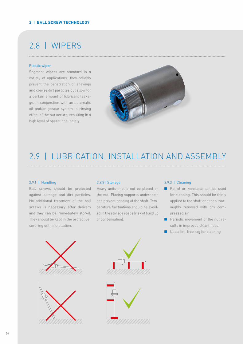
Plastic wiper
Segment wipers are standard in a
variety of applications: they reliably
prevent the penetration of shavings
and coarse dirt particles but allow for
a certain amount of lubricant leaka-
ge� In conjunction with an automatic
oil and/or grease system, a rinsing
effect of the nut occurs, resulting in a
high level of operational safety�
2.9.1 | Handling
Ball screws should be protected
against damage and dirt particles�
No additional treatment of the ball
screws is necessary after delivery
and they can be immediately stored�
They should be kept in the protective
covering until installation�
2.9.2 | Storage
Heavy units should not be placed on
the nut� Placing supports underneath
can prevent bending of the shaft� Tem-
perature fluctuations should be avoid-
ed in the storage space (risk of build up
of condensation)�
2.9.3 | Cleaning
n Petrol or kerosene can be used
for cleaning� This should be thinly
applied to the shaft and then thor-
oughly removed with dry com-
pressed air�
n Periodic movement of the nut re-
sults in improved cleanliness�
n Use a lint-free rag for cleaning
24
Steinmeyer Produktbroschüre Gerollte Kugelgewindetriebe EN-2016-05 v.1.15.indd 24 02.05.16 10:00

2.9.4 | Nut assembly
Before the nut can be mounted on the shaft, the following points should be
reviewed:
• Has the shaft been cleaned and aligned?
• Is the thread burr-free?
• Check desired nut orientation on the shaft (e�g� flange to the short journal
side?)
• Align nut mounting tube on the shaft accordingly
n Remove safety device
During transport, the nut is secured using cable tie or o ring� This must be
removed before installation�
Attention: It is important to ensure that the nut does not slide down the
tube as the balls can be lost.
n Positioning the tube at the top of the thread
Depending on the orientation, the tube (with nut) will either be positioned on
the long or short journal end of the shaft�
Attention: It is important to ensure that it rests flush with the thread.
n Installing the nut onto the shaft
The nut is now carefully pushed forward on the tube until the front edge of
the nut is right next to the shaft thread� Now the nut is carefully rotated onto
the shaft� There should be only minimal resistance� The following guideline
value applies: Threading force in [N] = 1/2-nominal-Ø [mm] (Threading
force is the force required for the area of the nut)�
The nut is then completely installed onto the shaft. NB: if the wiper be-
gins to dislodge stop, back off, and then try again holding the wiper in
place with your thumb as you rotate the nut onto the shaft.
n Removing the mounting sleeve
The mounting tube may only be removed if it is ensured that the nut is en-
tirely on the shaft, complete with balls and wipers�
n Removing the nut from the shaft
In order to remove the nut from the shaft, repeat the above process in re-
verse order, using a mounting tube�
2 | BALL SCREW TECHNOLOGY
25
Steinmeyer Produktbroschüre Gerollte Kugelgewindetriebe EN-2016-05 v.1.15.indd 25 02.05.16 10:00

2 | BALL SCREW TECHNOLOGY
2.9.5 | Installation
Because the lifespan of the ball screw
depends upon exact assembly, the
following points must be observed:
n Maximum cleanliness should be
observed� The ball screw should
not be removed from the package
until right before installation� If
necessary, clean and apply corro-
sion protection (either grease or
oil) to the shaft before assembly�
n In order to avoid hitting the slide,
the stroke limiter switch should be
installed and activated as soon as
possible�
n The shaft must be accurately
aligned with the guide tracks of the
machine parts to be moved�
Important: Do not unscrew the nut
beyond the thread of the shaft�
(if this happens, the complete ball
screw assembly should be returned
for inspection�)
Steinmeyer recommends that the
installation of the ball screw adhere
to the positional tolerance guidelines
specified here (fig� 1)� Optimal par-
allelism between the guide channel
and the ball screw drive axle, as well
as perpendicularity of the nut attach-
ment ensure that the drive unit is not
warped, thus achieving a longer life�
After the installation, ensure that
the ball screw drive can be freely
moved in all positions (depending on
pre-stressing)�
If the nut is at the outermost point on
the shaft or as close as possible to
the fixed bearing, possible warping
will be easiest to identify�
Any misalignment can lead to pre-
mature failure of the ball screw�
Fig. 1: Misalignment (shaft parallel to guideway)
Fig. 2: Tilt error (perpendicularity) surface for attaching the ball nut to the structure
T5 – T7*
T9 – T10*
T5 – T7*
T9 – T10*
Railguide
*T5-T7 = Lead accuracy ISO 3408 for
nuts with little or no clear-
ance
*T9-T10 = Lead accuracy ISO 3408
suitable for nuts with clear-
ance
// 0�03 AB
// 0�05 AB
0�03 AB
0�05 AB
26
Steinmeyer Produktbroschüre Gerollte Kugelgewindetriebe EN-2016-05 v.1.15.indd 26 02.05.16 10:00
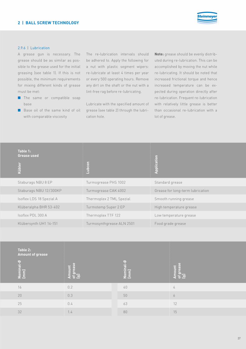
2.9.6 | Lubrication
A grease gun is necessary� The
grease should be as similar as pos-
sible to the grease used for the initial
greasing (see table 1)� If this is not
possible, the minimum requirements
for mixing different kinds of grease
must be met:
n The same or compatible soap
base
n Base oil of the same kind of oil
with comparable viscosity
The re-lubrication intervals should
be adhered to� Apply the following for
a nut with plastic segment wipers:
re-lubricate at least 4 times per year
or every 500 operating hours� Remove
any dirt on the shaft or the nut with a
lint-free rag before re-lubricating�
Lubricate with the specified amount of
grease (see table 2) through the lubri-
cation hole�
Note: grease should be evenly distrib-
uted during re-lubrication� This can be
accomplished by moving the nut while
re-lubricating� It should be noted that
increased frictional torque and hence
increased temperature can be ex-
pected during operation directly after
re-lubrication� Frequent re-lubrication
with relatively little grease is better
than occasional re-lubrication with a
lot of grease�
Staburags NBU 8 EP
Staburags NBU 12 / 300KP
Isoflex LDS 18 Spezial A
Klüberalpha BHR 53-402
Isoflex PDL 300 A
Klübersynth UH1 14-151
16
20
25
32
0�2
0�3
0�4
1�4
40
50
63
80
4
6
12
15
Turmogrease PHS 1002
Turmogrease CAK 4002
Thermoplex 2 TML Spezial
Turmotemp Super 2 EP
Thermoplex TTF 122
Turmosynthgrease ALN 2501
Standard grease
Grease for long-term lubrication
Smooth running grease
High temperature grease
Low temperature grease
Food grade grease
Table 1:Grease used
Table 2:Amount of grease
Küb
ler
Nom
inal
-Ø[m
m]
Nom
inal
-Ø[m
m]
Amou
ntof
gre
ase
[g]
Amou
ntof
gre
ase
[g]
Lubc
on
Appl
icat
ion
2 | BALL SCREW TECHNOLOGY
27
Steinmeyer Produktbroschüre Gerollte Kugelgewindetriebe EN-2016-05 v.1.15.indd 27 02.05.16 10:00

3 | ORDERING INFORMATION
3�1 | ORDER CODE
Order code
0 No nut (screw shaft only)2 Nut with end cap return3 Nut with through-the-nut return8 Nut with multiliner
0 No nut (screw shaft only)1 Nut with connecting thread4 Single flange nut
3 Rolled thread– one start4 Rolled thread – two or more starts
5 Screw shafts without nut4 Nut dimensions special version6 Flange nut dimensions according to ISO 34082 Dimensions according to Steinmeyer standards (for nuts with connecting thread)
… Lead
… Diameter (nominal)
… Ball diameter (for nuts on sleeve)
… Number of circuits (for nuts on sleeve)
… Thread length (different for screw shafts with journal machining)
… Total length (screw shafts)
T Transportation ball-screw… Tolerance class according to ISO 3408 (standard 7, classes 5, 9, 10 upon request)
V – Nut with axial clearance (mounted or single nuts on mounting sleeve)V0 Nut mounted free of clearance (approx� 0-2 % of Ca)V5 Nut mounted pre-stressed (approx� 5 % of Ca)
Z Bearing journals machined according to drawing- Without fixed bearing journal, cut and chamferedA Fixed bearing journal, machined according to catalogue standard
K Hexagonal socketG Center hole incl� internal threadN Keyway groove- Without machining options
- Without loose bearing journal, cut and chamferedB Loose bearing journal, machined according to catalogue standard
K Hexagonal socketG Center hole incl� internal thread- Without machining options
Mounting direction of nut flange or nut connecting thread (Option for mounted nut incl� final processing) x For long-machined journaly For short-machined journal
Example for ball screw drive with machined journals: 8436/5.25.410.500.T7.V0.A.KN.B.G.x
Example for nut on mounting sleeve: 8436/5.25.3,5.3
Example for shaft only: 0035/5.25.6000.6000 T7
(Example) 8 4 3 6 5 25 410 500 T7 V0 G xA KN B/ ..........
28
Steinmeyer Produktbroschüre Gerollte Kugelgewindetriebe EN-2016-05 v.1.15.indd 28 02.05.16 10:00
3 | ORDERING INFORMATION
3�2 | AVAILABILITY
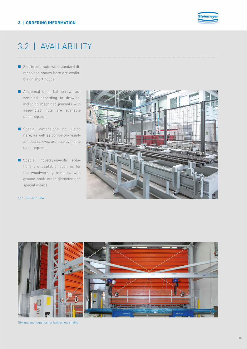
n Shafts and nuts with standard di-
mensions shown here are availa-
ble on short notice�
n Additional sizes, ball screws as-
sembled according to drawing,
including machined journals with
assembled nuts are available
upon request�
n Special dimensions not listed
here, as well as corrosion-resist-
ant ball screws, are also available
upon request�
n Special industry-specific solu-
tions are available, such as for
the woodworking industry, with
ground shaft outer diameter and
special wipers�
>>> Let us know�
Storing and logistics for ball screw shafts
29
Steinmeyer Produktbroschüre Gerollte Kugelgewindetriebe EN-2016-05 v.1.15.indd 29 02.05.16 10:00

4 | PRODUCTS
Type
5
10
5
10
20
5
10
20
25
5
10
20
32
16
16
20
20
20
25
25
25
25
32
32
32
32
3�5
3�5
3�5
3�5
3�5
3�5
3�5
3�5
3�5
3�5
6
6
6
3
3 + 3
3
3 + 3
2 + 2
3
3 + 3
2 + 2
2 + 2
4
3
2 + 2
1 + 1
10�1
19�6
12�1
22�8
14�7
13�7
25�2
17�1
16�7
20�4
30�8
39�3
18�2
12
27�4
16�7
36�5
22�4
21�5
45�4
29�5
29
39�8
45�6
63�6
26�5
Lead
P [m
m]
Nom
inal
dia
met
er
d N [m
m]
Ball
diam
eter
d W [m
m]
Num
ber
of c
ircu
its [i
]
Dyn
amic
load
ca
paci
ty C
a [kN
]
Stat
ic lo
adca
paci
ty C
0a [k
N]
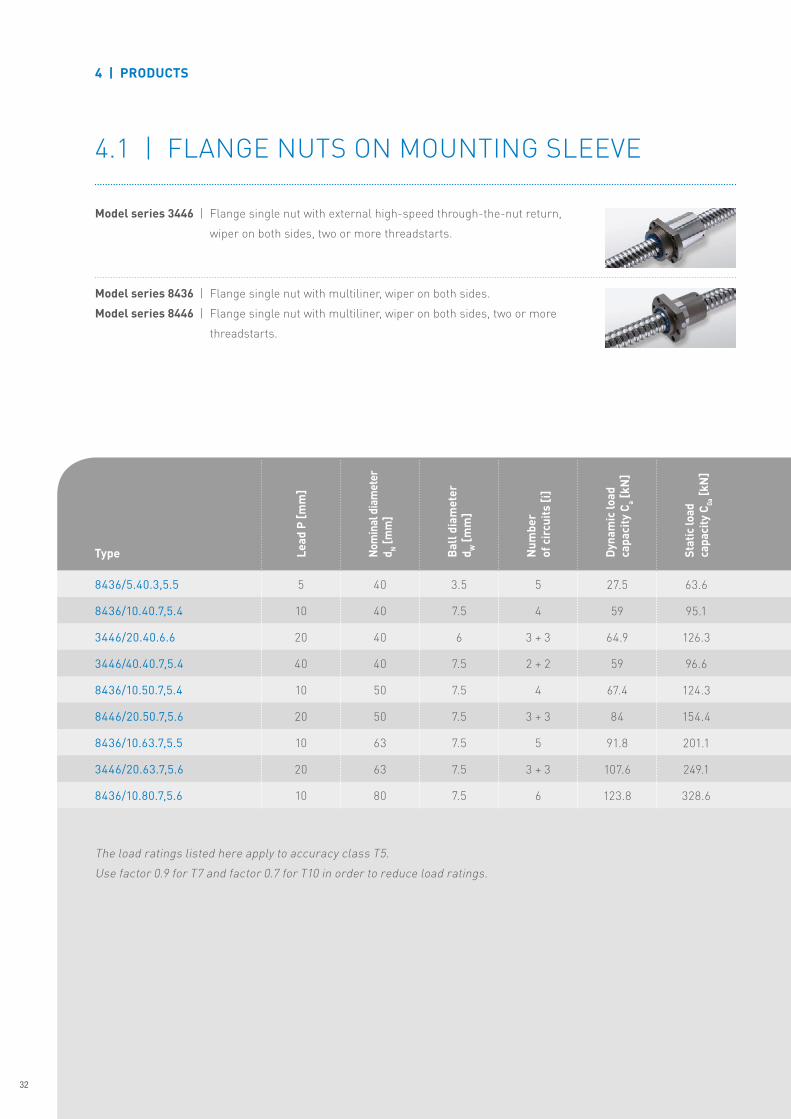
4�1 | FLANGE NUTS ON MOUNTING SLEEVES
Model series 2446 | Flange single nut with end cap return, wiper on both sides, two or more
threadstarts�
Model series 3446 | Flange single nut with external high-speed through-the-nut return,
wiper on both sides, two or more threadstarts�
Model series 8436 | Flange single nut with multiliner, wiper on both sides�
The load ratings listed here apply to accuracy class T5�
Use factor 0�9 for T7 and factor 0�7 for T10 in order to reduce load ratings�
8436/5.16.3,5.3
2446/10.16.3,5.6
8436/5.20.3,5.3
2446/10.20.3,5.6
2446/20.20.3,5.4
8436/5.25.3,5.3
2446/10.25.3,5.6
2446/20.25.3,5.4
2446/25.25.3,5.4
8436/5.32.3,5.4
8436/10.32.6.3
3446/20.32.6.4
3446/32.32.6.2
30
Steinmeyer Produktbroschüre Gerollte Kugelgewindetriebe EN-2016-05 v.1.15.indd 30 02.05.16 10:00

A
Wiper
Wiper
D1
g6
LF
L1
A*
D6
A*
D4
D1
±0,5
1D
1-
L3 L7
d N
Hole pattern 2
M8x1
H
30°
H
9 0 °
M6
Hole pattern 1
H2 2 ,5 °
90°
D5
H
4 | PRODUCTS
1
1
1
1
1
1
1
1
1
1
1
1
1
46
44
46
49
57
46
49
57
66
53
72
68
60 + 2x5*
28
32
36
36
36
40
40
40
40
50
50
56
56
Hol
e pa
tter
n
LF [m
m]
Ø D
1 g6
[mm
]
10
16
10
10
10
10
16
16
16
10
16
20
20
38
42
47
47
47
51
51
51
51
65
65
71
71
5�5
5�5
6�6
6�6
6�6
6�6
6�6
6�6
6�6
9
9
9
9
48
52
58
58
58
62
62
62
62
80
80
86
86
10
10
10
10
10
10
10
10
10
12
12
14
14
6
12
6
7
7
6
7
7
7
6
7
7
7 + 5*
20
20
22
22
22
24
24
24
24
31
31
32�5
32�5
L1 [m
m]
Ø D
4 [m
m]
Ø D
5 [m
m]
Ø D
6 [m
m]
L7 [m
m]
L3 [m
m]
H [m
m]
Continued on following page >>>
* Wiper overlap
Hole pattern 1, flange form B according to ISO 3408�
31
Steinmeyer Produktbroschüre Gerollte Kugelgewindetriebe EN-2016-05 v.1.15.indd 31 02.05.16 10:00
4 | PRODUCTS
5
10
20
40
10
20
10
20
10
40
40
40
40
50
50
63
63
80
3�5
7�5
6
7�5
7�5
7�5
7�5
7�5
7�5
5
4
3 + 3
2 + 2
4
3 + 3
5
3 + 3
6
27�5
59
64�9
59
67�4
84
91�8
107�6
123�8
63�6
95�1
126�3
96�6
124�3
154�4
201�1
249�1
328�6
4�1 | FLANGE NUTS ON MOUNTING SLEEVE
Model series 3446 | Flange single nut with external high-speed through-the-nut return,
wiper on both sides, two or more threadstarts�
Model series 8436 | Flange single nut with multiliner, wiper on both sides�
Model series 8446 | Flange single nut with multiliner, wiper on both sides, two or more
threadstarts�
Type Lead
P [m
m]
Nom
inal
dia
met
er
d N [m
m]
Ball
diam
eter
d W [m
m]
Num
ber
of c
ircu
its [i
]
Dyn
amic
load
ca
paci
ty C
a [kN
]
Stat
ic lo
adca
paci
ty C
0a [k
N]
The load ratings listed here apply to accuracy class T5�
Use factor 0�9 for T7 and factor 0�7 for T10 in order to reduce load ratings�
8436/5.40.3,5.5
8436/10.40.7,5.4
3446/20.40.6.6
3446/40.40.7,5.4
8436/10.50.7,5.4
8446/20.50.7,5.6
8436/10.63.7,5.5
3446/20.63.7,5.6
8436/10.80.7,5.6
32
Steinmeyer Produktbroschüre Gerollte Kugelgewindetriebe EN-2016-05 v.1.15.indd 32 02.05.16 10:00

A
Wiper
Wiper
D1
g6
LF
L1
A*
D6
A*
D4
D1
±0,5
1D
1-
L3 L7
d N
Hole pattern 2
M8x1
H
30°
H
9 0 °
M6
Hole pattern 1
H2 2 ,5 °
90°
D5
H
A
Wiper
Wiper
D1
g6
LF
L1
A*
±0,5
1D
1-
L3 L7
d N
Hole pattern 2
M8x13 0 °
H
30°
D5
H
9 0 °
M6
Hole pattern 1
H2 2 ,5 °
90°
D5
H
2
2
2
2
2
2
2
2
2
60
84
89
107
86
90
98
91
110
63
63
63
70
75
75
90
95
105
10
16
20
25
16
16
16
25
16
78
78
78
85
93
93
108
115
125
9
9
9
9
11
11
11
13�5
13�5
93
93
93
100
110
110
125
135
145
14
14
14
14
16
16
18
20
20
6
7
19�5
21
7
22
7
24
7
35
35
35
37�5
42�5
42�5
47�5
50
55
LF [m
m]
Ø D
1 g6
[mm
]
L1 [m
m]
Ø D
4 [m
m]
Ø D
5 [m
m]
Ø D
6 [m
m]
L7 [m
m]
L3 [m
m]
H [m
m]
Hol
e pa
tter
n
Hole pattern 2, flange form B according to ISO 3408�
4 | PRODUCTS
33
Steinmeyer Produktbroschüre Gerollte Kugelgewindetriebe EN-2016-05 v.1.15.indd 33 02.05.16 10:00

4 | PRODUCTS
5
5
5
10
5
10
5
10
10
10
10
16
20
25
25
32
32
40
40
50
63
80
3�5
3�5
3�5
3�5
3�5
6
3�5
7�5
7�5
7�5
7�5
4
4
5
2 + 2
5
4
5
5
6
6
6
12�9
15�5
21�2
16�1
24�8
39�4
27�5
71�5
95�6
107�4
123�8
16
22�3
35�9
25�5
49�7
60�8
63�6
118�9
186�5
241�3
328�6
4�2 | NUTS WITH CONNECTING THREAD ON MOUNTING SLEEVE
Model series 8132 | Nut with connecting thread with multiliner, wiper on both sides�
Model series 8142 | Nut with connecting thread with multiliner, wiper on both sides, two or
more threadstarts�
Type Lead
P [m
m]
Nom
inal
dia
met
er
d N [m
m]
Ball
diam
eter
d W [m
m]
Num
ber
of c
ircu
its [i
]
Dyn
amic
load
ca
paci
ty C
a [kN
]
Stat
ic lo
adca
paci
ty C
0a [k
N]
The load ratings listed here apply to accuracy class T5�
Use factor 0�9 for T7 and factor 0�7 for T10 in order to reduce load ratings�
8132/5.16.3,5.4
8132/5.20.3,5.4
8132/5.25.3,5.5
8142/10.25.3,5.4
8132/5.32.3,5.5
8132/10.32.6.4
8132/5.40.3,5.5
8132/10.40.7,5.5
8132/10.50.7,5.6
8132/10.63.7,5.6
8132/10.80.7,5.6
34
Steinmeyer Produktbroschüre Gerollte Kugelgewindetriebe EN-2016-05 v.1.15.indd 34 02.05.16 10:00

Wip
er Lubrication hole
For pin wrench
Wip
er
L 13 ±2
L ±1
D 1
±0,
3
L 12 ±2
D 1
1
D 13 ±0,1
L 11 ±0,5
MD 12
d N57�5
57�5
63�5
61
65�5
85
67�5
105�5
118
118
126
32
38
42
42
52
52
58
65
78
92
120
16�5
16�5
17
17
19
19
19
27
29
29
34
L [m
m]
Ø D
1 [m
m]
L11
[mm
]
M30x1�5
M35x1�5
M40x1�5
M40x1�5
M48x1�5
M48x1�5
M56x1�7
M60x2
M72x2
M85x2
M110x2
10�5
10�5
10�5
10
10�5
12
12
13
13
13
15�5
M6x1
M6x1
M6x1
M6x1
M6x1
M6x1
M8x1
M8x1
M8x1
M8x1
M8x1
22
22
23
21
23
43
22�5
43
53
53
53
4
4
4
4
5
5
5
6
6
6
8
Ø D
11 [m
m]
L12
[mm
]
Ø D
12 [m
m]
L13
[mm
]
Ø D
13 [m
m]
4 | PRODUCTS
35
Steinmeyer Produktbroschüre Gerollte Kugelgewindetriebe EN-2016-05 v.1.15.indd 35 02.05.16 10:00

4 | PRODUCTS
4�3 | SCREW SHAFTS
0035/5.16.3000.3000 T7
0045/10.16.3000.3000 T7
0035/5.20.3000.3000 T7
0045/10.20.3000.3000 T7
0045/20.20.3000.3000 T7
0035/5.25.6000.6000 T7
0045/10.25.6000.6000 T7
0045/20.25.6000.6000 T7
0045/25.25.6000.6000 T7
0035/5.32.6000.6000 T7
0035/10.32.6000.6000 T7
5
10
5
10
20
5
10
20
25
5
10
Lead
P [m
m]
1
2
1
2
4 (2)
1
2
4 (2)
5 (2)
1
1
Num
ber
of th
read
s5
5
5
5
5 (10)
5
5
5 (10)
5 (12�5)
5
10
Pitc
h [m
m]
3000
3000
3000
3000
3000
6000
6000
6000
6000
6000
6000
Max
imum
Leng
th [m
m]
Order code
Standard accuracy class T7 (T5, T9, T10 upon request)�
Additional charge for shorter lengths (cut lengths)�
Length tolerance: 3 m -0�05 +0�1 m, 6 m -0�1 +0�15 m�
Straightness 0�2 mm/m spindle shaft�
2 x approx� 10 – 15 cm unhardened area on each screw shaft end�
(Used threads)�
16
16
20
20
20
25
25
25
25
32
32
Nom
inal
dia
met
er
d N [m
m]
12�9
12�9
16�9
16�9
16�9
21�9
21�9
21�9
21�9
28�9
26�8
Core
dia
met
er
[mm
]
3�5
3�5
3�5
3�5
3�5
3�5
3�5
3�5
3�5
3�5
6
Ball
diam
eter
d W [m
m]
36
Steinmeyer Produktbroschüre Gerollte Kugelgewindetriebe EN-2016-05 v.1.15.indd 36 02.05.16 10:00

0045/20.32.6000.6000 T7
0045/32.32.6000.6000 T7
0035/5.40.6000.6000 T7
0035/10.40.6000.6000 T7
0045/20.40.6000.6000 T7
0045/40.40.6000.6000 T7
0035/10.50.6000.6000 T7
0045/20.50.6000.6000 T7
0035/10.63.6000.6000 T7
0045/20.63.6000.6000 T7
0035/10.80.6000.6000 T7
20
32
5
10
20
40
10
20
10
20
10
Lead
P [m
m]
32
32
40
40
40
40
50
50
63
63
80
Nom
inal
dia
met
erd N
[mm
]
6
6
3�5
7�5
6
7�5
7�5
7�5
7�5
7�5
7�5
Ball
diam
eter
d W [m
m]
2
4 (2)
1
1
2
4 (2)
1
2
1
2
1
Num
ber
of th
read
s
10
8 (16)
5
10
10
10 (20)
10
10
10
10
10
Pitc
h [m
m]
6000
6000
6000
6000
6000
6000
6000
6000
6000
6000
6000
Max
imum
Leng
th [m
m]
Order code
26�8
26�8
36�4
33�3
34�3
33�3
43�3
43�3
56�3
56�3
73�3
Core
dia
met
er
[mm
]
4 | PRODUCTS
37
Steinmeyer Produktbroschüre Gerollte Kugelgewindetriebe EN-2016-05 v.1.15.indd 37 02.05.16 10:00

nm
n1
q1
n2
q2n
[rpm
]
100
n3
q3 q [%]
Fm
F1
q1
F2
q2
F [N
]
100
F3
q3 q [%]
Fm = Dynamic equivalent axial Load [N]
Fi = Actual Load [N]
ni = Actual Speed [rpm]
qi = Time of each duty cycle [%]
nm = Average speed [rpm]
5 | SELECTION GUIDE
5�1 | SERVICE LIFE
5.1.1 | Load capacity selection
Ball screws usually will be used car-
rying axial loads under dynamic con-
ditions� The selection therefore has to
take into consideration the load and
the travel - or number of revolutions
- made under this load� The normal
service life expectancy is based on the
fatigue of the material of the balls, and
raceways�
5.1.2 | Dynamic axial load capacity Ca
Basically, travel made under higher
load will determine the actual service
life more than travel made under low-
er loads� As hardly any application will
give a constant load, a mean load must
be calculated, which will result in the
same service life� This so-called dy-
namic equivalent axial load Fm is then
to be compared with the dynamic axial
load capacity Ca�
For simplification, a typical work cycle
of the machine under design should be
described along with load and load di-
rection, percentage of time and speed
for every step�
In the simplest case - non-preloaded
single nut - these values can be con-
verted to the dynamic equivalent axial
load Fm and the average speed nm by
means of the following formulas:
Fm= [N]1/3q1 · n1 · F1
3 + q2 · n2 · F23 + … + qz · nz · Fz
3
q1 · n1 + q2 · n2 + … + qz · nz
nm= [rpm]q1 · n1 + q2 · n2 + … + qz · nz
q1 + q2 + … + qz
38
Steinmeyer Produktbroschüre Gerollte Kugelgewindetriebe EN-2016-05 v.1.15.indd 38 02.05.16 10:00

Fm=Ca
L10
106
1/3[N]
1/3Ca = Fm· [N]
L10
106
106 ≦ L10 ≦ 109
[rev�]
L10= · 106 [rev�]3Ca
Fm
Ca= Pi· 4�45 [N]1/325�4
P
Fm = Dynamic equivalent axial load [N]
Ca = Dynamic axial load capacity [N]
L10 = Nominal service life [rev�]
P = Lead [mm]
Pi = Dynamic axial load capacity [LBS]:
ANSI 5�48
5 | SELECTION GUIDE
The dynamic load capacity for a ball
screw listed in the catalog is based on
the ISO 3408 / DIN 69051 calculations�
This dynamic load capacity is the axi-
al load Fm, under which the ball screw
will show a service life of 1 million
revolutions (L10 rating)�
To convert the dynamic load capacity
from ISO 3408/DIN 69051 to ANSl 5�48
1977, the following equation should be
used�
The resulting actual service life ex-
pectancy should be in the range of:
It is not recommended to rely on
service life expectancies outside the
above range�
39
Steinmeyer Produktbroschüre Gerollte Kugelgewindetriebe EN-2016-05 v.1.15.indd 39 02.05.16 10:00
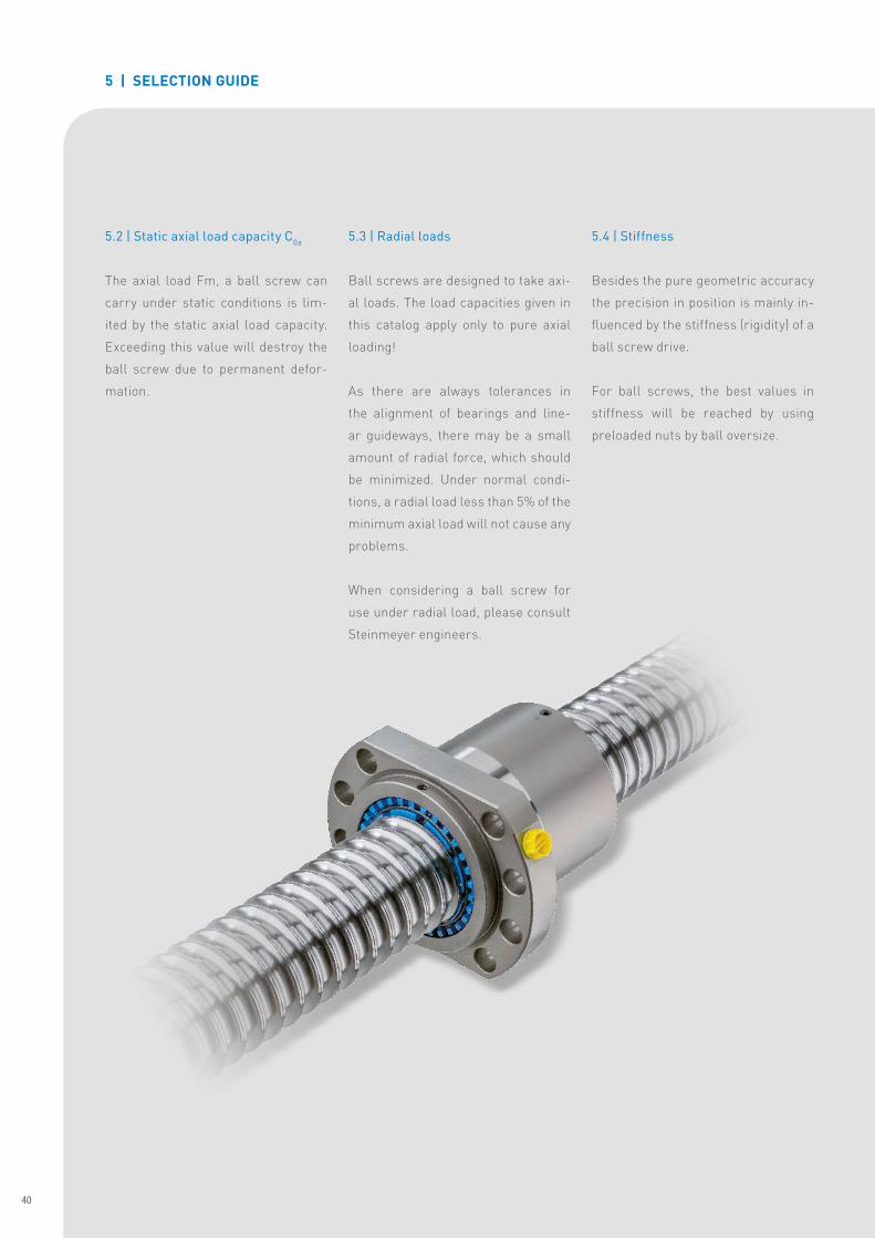
5.2 | Static axial load capacity C0a
The axial load Fm, a ball screw can
carry under static conditions is lim-
ited by the static axial load capacity�
Exceeding this value will destroy the
ball screw due to permanent defor-
mation�
5.3 | Radial loads
Ball screws are designed to take axi-
al loads� The load capacities given in
this catalog apply only to pure axial
loading!
As there are always tolerances in
the alignment of bearings and line-
ar guideways, there may be a small
amount of radial force, which should
be minimized� Under normal condi-
tions, a radial load less than 5% of the
minimum axial load will not cause any
problems�
When considering a ball screw for
use under radial load, please consult
Steinmeyer engineers�
5.4 | Stiffness
Besides the pure geometric accuracy
the precision in position is mainly in-
fluenced by the stiffness (rigidity) of a
ball screw drive�
For ball screws, the best values in
stiffness will be reached by using
preloaded nuts by ball oversize�
5 | SELECTION GUIDE
40
Steinmeyer Produktbroschüre Gerollte Kugelgewindetriebe EN-2016-05 v.1.15.indd 40 02.05.16 10:00
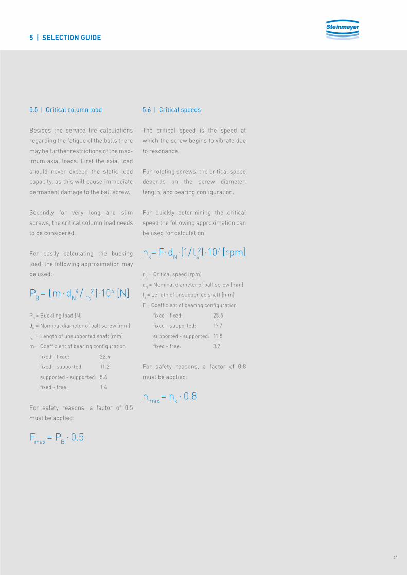
5.5 | Critical column load
Besides the service life calculations
regarding the fatigue of the balls there
may be further restrictions of the max-
imum axial loads� First the axial load
should never exceed the static load
capacity, as this will cause immediate
permanent damage to the ball screw�
Secondly for very long and slim
screws, the critical column load needs
to be considered�
For easily calculating the bucking
load, the following approximation may
be used:
PB = (m·dN4 / ls
2 )·104 [N]
PB = Buckling load [N]
dN = Nominal diameter of ball screw [mm]
ls = Length of unsupported shaft [mm]
m= Coefficient of bearing configuration
fixed - fixed: 22�4
fixed - supported: 11�2
supported - supported: 5�6
fixed - free: 1�4
For safety reasons, a factor of 0�5
must be applied:
Fmax = PB · 0�5
5.6 | Critical speeds
The critical speed is the speed at
which the screw begins to vibrate due
to resonance�
For rotating screws, the critical speed
depends on the screw diameter,
length, and bearing configuration�
For quickly determining the critical
speed the following approximation can
be used for calculation:
nk= F·dN ·(1/ ls
2)·107 [rpm]
nk = Critical speed [rpm]
dN = Nominal diameter of ball screw [mm]
ls = Length of unsupported shaft [mm]
F = Coefficient of bearing configuration
fixed - fixed: 25�5
fixed - supported: 17�7
supported - supported: 11�5
fixed - free: 3�9
For safety reasons, a factor of 0�8
must be applied:
nmax = nk · 0�8
5 | SELECTION GUIDE
41
Steinmeyer Produktbroschüre Gerollte Kugelgewindetriebe EN-2016-05 v.1.15.indd 41 02.05.16 10:00

6 | NOTES
42
Steinmeyer Produktbroschüre Gerollte Kugelgewindetriebe EN-2016-05 v.1.15.indd 42 02.05.16 10:00

6 | NOTES
43
Steinmeyer Produktbroschüre Gerollte Kugelgewindetriebe EN-2016-05 v.1.15.indd 43 02.05.16 10:00
EN-0
03-2
016-
05 |
We
rese
rve
the
righ
t to
mak
e te
chni
cal c
hang
es w
ithou
t pri
or n
otic
e� |
Typ
ing
and
prin
ting
erro
rs r
eser
ved�
www.artistic.de
WE ARE STEINMEYER�
DRIVING POSITIONING MEASURING
August Steinmeyer GmbH & Co. KG
Riedstraße 7
72458 Albstadt
Phone +49 (0) 7431 1288-0
Fax +49 (0) 7431 1288-89
E-Mail [email protected]
Internet: www.steinmeyer.com
Steinmeyer Mechatronik GmbH
Fritz Schreiter Str.32
01259 Dresden
Phone +49 (0) 351 88585-0
Fax +49 (0) 351 88585-25
E-Mail [email protected]
Internet: www.steinmeyer.com
Feinmess Suhl GmbH
Pfütschbergstraße 11
98527 Suhl
Phone +49 (0) 3681 381-0
Fax +49 (0) 3681 381-105
E-Mail: [email protected]
Internet: www.feinmess-suhl.com
Steinmeyer Produktbroschüre Gerollte Kugelgewindetriebe EN-2016-05 v.1.15.indd 44 02.05.16 10:00