role of dc-mli based d-statcom in distribution network
TRANSCRIPT

ROLE of DC-MLI based D-STATCOM in DISTRIBUTION
NETWORK with FOC INDUCTION MOTOR DRIVE
A Dissertation
Submitted in partial fulfilment of the requirements for the
Award of degree of
MASTER OF ENGINEERING
in
POWER SYSTEMS
Submitted By:
SURBHI AGGARWAL
Reg. No.: 801542021
Supervised By:
Dr. PARAG NIJHAWAN
Assistant Professor, EIED
JULY 2017
ELECTRICAL & INSTRUMENTATION ENGINEERING
DEPARTMENT
THAPAR UNIVERSITY, PATIALA-147004


ii
Acknowledgement
I am grateful to the Electrical and Instrumentation Engineering Department for giving
the opportunity to execute this thesis which is an integral part of the curriculum in M.E.
Power Systems at the Thapar University.
This work would not have been possible without the encouragement and able guidance
of my supervisor, Dr. Parag Nijhawan. Their enthusiasm and optimism made this experience
both rewarding and enjoyable. Most of the novel ideas and solution found in this thesis are
the result of our numerous stimulating discussions. Their feedback and editorial comments
were invaluable for the writing of this thesis.
I would like to express my deep sense of gratitude toward Dr. Ravinder Agarwal,
Professor and Head, EIED, Thapar University, Patiala .
I would also like to thank all the faculty members of the department and my friends who
have directly or indirectly helped me in completion of my thesis.
(Surbhi Aggarwal)
Regn. No.: 801542021

iii
Abstract
The main objective of Power System engineers is to meet the consumers demand. Rated
voltage and rated frequency supply should be supplied to the consumer end.With the
introduction of many non-linear loads at the consumer end, Power Quality problem is a
serious threat to the Power System. Power Quality problem is any occurrence in voltage,
current or frequency deviation that may result in failure or mis-operation of electrical
appliances.Common Power Quality problems that can be observed in daily life are voltage
sag, voltage swell, voltage flickering, over-voltage and under-voltage. Impulsive transients,
oscillatory transients and harmonics are also some of the Power Quality problems.
The potency of D-STATCOM using SRF control theory in a Distribution Network with Field
Oriented Control (FOC) Induction Motor drive as non-linear load with Diode-Clamped
Multilevel inverter is examined. The FOC induction motor drive is a non-linear load which
introduces harmonics into the distribution network when operated. D-STATCOM is a shunt
linked device used for the reactive power compensation, for harmonic elimination and load
balancing. D-STATCOM is a Custom Power device used at the distribution end to counteract
the Power Quality problem.
The conceptualization of Multilevel inverters came around 1975. For high-power and
medium-power applications, Multilevel inverters are used as they can extract input current
and produce output voltage with very low distortion. They even reduce the dv/dt stress and
can operate at both fundamental switching frequency and high switching frequency. All these
benefits cannot be retained through conventional VSI and CSI. These can generate output
voltages with mature medium-power semi conductor technology with lower distortion. As the
number of levels increases, the output waveform approaches more towards sinusoidal wave
with a reduced harmonic distortion.
Simulation of D-STATCOM using SRF control theory with 7 level Diode-Clamped
Multilevel Inverter has been performed in MATLAB/SIMULINK.

iv
Table of Contents
Certificate i
Acknowledgement ii
Abstract iii
List of Figures vi
List of Tables vii
List of Abbreviations viii
Chapter 1: Overview 1-8
1.1 Introduction 1
1.2 Literature Review 2
1.3 Scope of Work 7
1.4 Objective of Thesis 7
1.5 Organization of Thesis 8
Chapter 2: Custom Power devices 9-12
2.1 Introduction 9
2.2 Compensating Devices 9
2.2.1 Distribution Static Compensator - D-STATCOM 9
2.2.2 Dynamic Voltage Restorer-DVR 10
2.2.3 Unified Power Quality Compensator-UPQC 11
Chapter 3: Distribution Static Compensator - D-STATCOM 13-18
3.1 Introduction 13
3.2 Configuration of D-STATCOM 14
3.2.1 Voltage Source Converter 14
3.2.2 Coupling Transformer 14
3.2.3 DC Capacitor Voltage 14
3.2.4 LC passive Filter 15
3.3 Applications/Advantages of D-STATCOM 15
3.4 Control Strategy for D-STATCOM – SRF Theory 16
Chapter 4: Multilevel Converters 19-25
4.1 Introduction 19
4.2 Multilevel Inverter 21
4.2.1 Diode-Clamped Multilevel Inverter 21

v
4.2.2 Flying Capacitor Multilevel Inverter 21
4.2.3 Cascaded H-Bridge Multilevel Inverter 22
4.3 Diode-Clamped Multilevel Inverter (DC-MLI) 23
4.3.1 Advantages of DC-MLI 25
4.3.2 Disadvantages of DC-MLI 25
Chapter 5: System Test and Results 26-32
5.1 Introduction 26
5.2 Parameters of the Test System 26
5.3 MATLAB/SIMULINK Results 27
Chapter 6: Conclusions and Future Scope 33
6.1 Conclusions 33
6.2 Future Scope 33
References 34-36

vi
List of Figures
Figure No. Caption of Figure Page no.
Figure 2.1 Schematic plan of D-STATCOM 10
Figure 2.2 Schematic plan of DVR 11
Figure 2.3 Schematic plan of UPQC 11
Figure 3.1 Basic structure of D-STATCOM 13
Figure 3.2 Configuration of D-STATCOM 15
Figure 3.3 Schematicplan of SRF based theory 17
Figure 3.4 Reference Frames 17
Figure 4.1 Flowchart for High Power Factor Converters 19
Figure 4.2 General topology for Multilevel Inverters 20
Figure 4.3 3-level Diode-Clamped Multilevel Inverter 21
Figure 4.4 3-level Flying Capacitor Multilevel Inverter 22
Figure 4.5 3-level Cascaded H-Bridge Multilevel Inverter 22
Figure 4.6 Simulation of 7-level Diode-Clamped MLI 23
Figure 4.7 Output waveform of 7-level Diode-Clamped MLI 24
Figure 5.1 MATLAB/SIMULINK model of Test System 28
Figure 5.2 Output Waveform of Source Phase Voltage 29
Figure 5.3 Frequency Spectrum of Source Phase Voltage 29
Figure 5.4 Output Waveform of Source Current 30
Figure 5.5 Frequency Spectrum of Load Voltage 30
Figure 5.6 Output Waveform of Load Current 31
Figure 5.7 Frequency Spectrum of Load Current 31
Figure 5.8 Output Waveform of Compensated Current 32
Figure 5.9 Frequency Spectrum of Compensated Current 32

vii
List of Tables
Table No. Caption of Table PageNo.
Table 5.1 System Parameters 27

viii
List of Abbreviations
APOD Alternative Phase Opposite Dissipation
BESS Battery Energy Storage System
CP Custom Power device
CSI Current Source Inverter
DC-MLI Diode-Clamped Multilevel Inverter
D-STATCOM Distribution Synchronous Compensator
DVR Dynamic Voltage Restorer
FACTS Flexible AC Transmission System
FFT Fast Fourier Transform
FOC Field Oriented Control
IEC International Electro technical Commission
IEEE Institute of Electrical and Electronics Engineers
IGBT Insulated Gate Bipolar Transistor
IRP Instantaneous Reactive Power theory
MLI Multilevel Inverter
PCC Point of Common Coupling
PD Phase Dissipation
POD Phase Opposition Dissipation
PQ Power Quality
PWM Pulse Width Modulation
STATCOM Synchronous Compensator
SRF Synchronous Reference Frame theory
THD Total Harmonic Disorder
UPQC Unified Power Quality Compensator
VSI Voltage Source Inverter
1
Chapter- 1
Overview
1.1 Introduction
Power System is a subsystem of Electrical Engineering which composes of the generating,
transmiting and distributing sections of the electric power.It is the chief duty of Power System
engineers is to meet the consumers electric power demand. Rated voltage and rated frequency
supply should be supplied to the end user. With the advance need of energy, Renewable
energy is included in the subsisting Power System. With the beginning of the Power
Electronics into the subsisting system, the consumer demand is fulfilled upto a certain extent
but the Power Quality problem is now one of the chief concerns of Power engineers.
With the introduction of many non-linear loads at the consumer end, Power Quality
problem is a serious threat to the Power System. As perIEEE,―Power Quality is the concept
of powering and grounding sensitive equipment in a matter that is suitable to the operation of
that equipment‖. Common Power Quality problems that can be observed in daily life are
Voltage Sag, Voltage Swell, Voltage Flickering, Over-Voltage and Under-Voltage. Impulsive
transients, Oscillatory transients and Harmonics are also Power Quality problems.
For the Harmonic elimination, passive, active and hybrid power filters are used. At the
distribution side, Custom Power devices are used which mainly include Unified Power
Quality Conditioner (UPQC), Distribution Static Compensators (D-STATCOM) and
Dynamic Voltage Restorer (DVR).
D-STATCOM, a shunt linkedCustom Power deviceemployed for the reactive power
compensation at the distribution side whereas STATCOM is also a shunt linked device
employed in the transmission system for the power factor improvement and the voltage
stability.
D-STATCOM is also used for elimination of harmonic level and balancing of the loads at the
distribution end. Various control algorithms for extracting the reference source current
components are defined in the literature to analyze the performance of D-STATCOM such as
Instantaneous Reactive Power (IRP) theory, Adaline Based Control Algorithm, Load
balancing,Synchronous Reference Frame (SRF) theory, Symmetrical Component Theory and
many others. Among from all, IRP and SRF control algorithms are usually used.

2
Inverter, one of the Power Electronic conversion device from DC input to AC output. AC
output serves as an input to Adjustable Speed Drives (ASDs); Flexible AC Transmission
System (FACTS); Static VAR Compensators (SVCs); Active Filters; and many more. These
could be classified as Voltage Source Converters (VSIs) and Current Source Inverters (CSIs)
and are basically used for low and medium voltage applications. But for high-power
applications, conventional VSIs and CSIs cannot be used because of their high device rating
issues and more switching losses.
Multilevel inverter finds usage in many industrial high power applications. Multilevel
inverters were introduced in 1975 beginning with3 level Multilevel inverter. Multilevel
inverters produce output with more number of voltage levels, producing a more sinusoidal
voltage waveform and however reducing the harmonic distortion in the system. Multilevel
inverters are superior to conventional VSIs and CSIs due to their low distortion in the output
voltage waveform and reducing the dv/dt stress on the switches. Operating at fundamental
and high switching frequency, Multilevel inverters extracts very low distorted value of input
current. One negative point is that Multilevel inverters depend on more number of switching
devices and separate control circuitry is required for each switch which however increases the
cost and complexity of the system.
1.2 Literature Survey
In recent years, usage of non-linear loads like ASDs, SPS, arc furnaces and other equipments
is greater than before. Due to the running of non-linear loads, Power Quality problem arises in
Power System. Many researcheshave been done onCustom Power devices to enhance the
current and voltage quality. A brief literature review related to Power Quality, its
improvement using D-STATCOM is presented here:
Francois D. M., et al.[1]presented the detailed summary of the surveys conducted in last two
decades showing about the different origins and types of disturbances Rated voltage and rated
frequency supply has to be supplied to the consumers. Also, different types of monitoring
instruments are described.
D.G. Flinn, et al. [2] presented a paper focussing on various Power Quality problems that
subsist in the Power System alongside with their method to identify these problems. The data
collected from routine checks and on- site field measurements help to recognize the nature of
the Power Quality problem and the method to clarify that problem.

3
D.J. Ward, et al. [3] studied about the two different perspectives of Power Quality problems.
Power Quality problem viz. Short duration transients or momentary disturbances affect both
the utility side and consumer side. One aspect is from utility side meter which covers any of
the Power System disturbances that originates at the utility side and affects the customer’s
equipment whereas second aspect is from the customer side meter in which the problems are
restricted to the customer end only. This paper surveys into the power interrelated problems
which are in the direct of the utility and by the user itself.
A. Sannino, et al. [4] presentedaboutPower Quality problem reduction using FACTS
controllers such as STATCOM and D-STATCOM. Various power electronic devices are used
to mitigate Power Quality issues, for example, low power factor, poor voltage, current and
voltage harmonics and many more. These Power Quality problems mainly arise because of
swiftadjustments in the field excitation of Synchronous generator, unexpected increment in
the load or abrupt occurrence of faults in the Power System.
B. Singh, et al. [5] surveyed about the Custom Power devices along with their advantagesand
drawbacks. Power electronics based devices are being used to mitigate the Power Quality
problem. Various mitigating appliancesare used at the distribution end known as Custom
Power devices as well as at the transmission side classified as FACTS devices. Also some
comparisons are done between the traditional mitigation methods and some Custom Power
devices. Shunt devices are used to protect the source from the load whereas series devices are
used to protect load from the source.
A.A. Peter, et al. [6] surveyed about the impact of Power Quality issue on the execution of an
Induction motor drive.Induction Motor is not a linear load which utilized mostly at the
consumer end.With the help of MATALB Simulink, the execution of the Induction Motor is
predicted. Simulink results show the difference between execution of an induction motor in
case of unbalanced voltagesources and balanced voltagesources.
N.S. Rao, et al. [7] presented the Modelling and Simulation of D-STATCOM for
compensation of voltage sag problem. The present Power System is in the direction of
distributed and dispersed generation; Power Quality problem is one of the significant
concerns of Power Engineers. To mitigate the Power Quality problem at distribution
end,Custom Power devices are used. Various control algorithms are used for Simulation of D-
STATCOM. This paper focuses on the functioning of D-STATCOMon occurrence of a
single–line to ground (SLG) fault and measures to be taken to enhance the Power Quality
problem.

4
N. Kaur, et al. [8] studied about the switching transients originated at the distribution end due
to the usage of inductive load.With the increase in demand of power supply, present Power
System network is operated at its full capacity. Huge power loss and security issues are there.
The present Power System has to be smart and aware, fault-tolerant and self-healing. This
paper analyses the performance of D-STATCOM for 2 inductive loads viz. 2095.91kW and
3424.31kW. The different transient conditions are generated by connecting and disconnecting
the loads at different intervals of time.
B. Singh, et al. [9] surveyed about thecomparison of 3 control algorithms of DSTACOM viz.
IRP theory, SRF theory and Adaline based algorithm. Different control algorithms of D-
STATCOM for reparation of reactive power and unbalanced produced by various loads in
Power System are defined in literature.Diverse simulation and tests are done to exhibit the
performance of these control algorithms.
E. Varghese, et al. [10] presented the design, analysis and comparison of D-STATCOM in
MATALB Simulink for various types of loads like linear, non-linear and unbalanced load.D-
STATCOM, a shunt attacheddeviceemployed for reactive power compensation, source
current balancing at distribution end. IRPT, SRF, Adaline based algorithm, Back propagation
are some of the control algorithms for the analysis of D-STATCOM.
T. Rakesh, et al. [11] surveyed the SRF control of Diode-Clamped MLI basedD-
STATCOMwith Synchronous organization based management for harmonic mitigation.IRP
theory, SRF theory and Adaline based algorithm are some of the mostly used control
algorithms for D-STATCOM. In place of two level inverters Multilevel inverters are being
used nowadays. Comparison is done between two-level, 3-level MLI and five-level MLI.
R Sharma, et al. [12] presented the functioning of D-STATCOM with FOC Induction Motor
drive as load with dq0 transformation to investigate the performance of D-
STATCOM.Nowadays mostly used loads at distribution end are non-linear loads. Induction
Furnace load is one of the common non-linear loads used in the industries. FOC Induction
motor drive introduces obvious measure of load current harmonics, which additionally
influences the alternate loads linked in the system.
R.B. Vasa [13] presented the SRF control algorithm for Power Quality improvement using
MATALB Simulink to demonstrate the satisfactory behaviour of D-STATCOM.Poor voltage
regulation, high reactive power, load balancing, voltage sag-swell are some of the Power
Quality problems. Various control algorithms like IRPT, SRF theory, Adaline based
algorithm are used to overcome these Power Quality problems.

5
P. Nijhawan, et al.[14] surveyed about the Multilevel inverter based D-STATCOM.FOC-
Induction furnace load is one of the common non linear loads used in various industries at the
consumer end. Induction furnace load when operated introduces a substantialamount of load
current harmonics which have an effect on the other equipments linked to the system. On
conventional basis, two phase VSIwere employed in the model of D-STATCOM but
nowadays Multilevel inverters have replaced the conventional inverters. This paper shows the
comparison ofPWM based D-STATCOM andCarrier Phase Shift (CPS)PWM 5 level inverter
based D-STATCOMand results are inferred on comparison basis.
M. Bansal, et al. [15] presented about Instantaneous Reactive Power theory i.e. conversion of
a-b-c coordinates to α-β-0 coordinates to mitigate the current harmonics when induction
furnace drive used as non-linear load. Nowadays Power Quality problem is an important
subject for Power System network as well as to Power System engineers. Power Quality
problem includes voltage sag, voltage swell, interruptions, harmonics and many more which
may lead to interruption or failure of equipments. Various control algorithms are used to
overcome these Power Quality problems.
A. Singh, et al. [16] presentedthe improved performance of D-STATCOM and Battery
Energy Storage System (BESS) by modelling and controlto improve Power Quality.SRF
theory is used as the control algorithm forD-STATCOM and BESS for linear and non-linear
loads under balanced and dynamic conditions.
K.S.Varaprasad, et al. [17] presented the comparison between D-STATCOM and DVR
using MATALAB Simulink with the help of PI controller at the distribution side for static
linear and non-linear loads under different fault conditions. About 90% of the average
customer interruptions occur at distribution side which accounts for a huge amount of
financial losses and loss of productivity.
J.A. Barrena et al. [18] presented the two different design methodologies of D-
STATCOMMultilevel topologies. Neutral Point Clamped (NPC) Multilevel topology and
Cascaded H-Bridge Multilevel topology for D-STATCOM relevance have been presented.
Special consideration is given on the capacitor value of DC bus and inductance value of
output filter.
B. Singh et al. [19] presented the application of D-STATCOM for easing of Power Quality
problems at distribution end. D-STATCOM, linked in shunt with an isolated alternator system
(42.5 kVA, 400V) feeding non-linear load is modelled in MATLAB/SIMULINK and PSB.

6
Voltage dip problem arises on the sudden application of induction motor at load end.
Comparison between with and without D-STATCOM controller is done.
L.M. Tolbert et al. [20] presented the transformerless Multilevel converters for high-power
drives and/or high-voltage electric motor drives. These converters are better than conventional
VSIs and CSIs as they can operate on high switching frequency and on fundamental switching
frequency. Simulation and comparison of Cascaded Multilevel inverter and back-to-back
Diode-ClampedMultilevel inverter is presented.
S. Iyer, et al. [21] surveyed about the distinctive topologies of inverters for performing a D-
STATCOM. A Voltage Source Inverter (VSC) is one of the main components of the D-
STATCOM model. The compensation provided by inverter depends on the configuration of
the inverter. Simulation study of 3-stage inverter with a single DC capacitor, 3- stage inverter
with Neutral Point Clamped DC capacitors, 4-stage inverter and 3-single phase inverters with
common DCcapacitor is described.
J.S. Lai, et al. [22] discussed 3 designs available for the Multilevel inverters namely FC-MLI,
DC-MLI, Cascaded H-Bridge MLI for high power applications. At the output terminals of
Multilevel inverter, more than two voltage levels are available which can be approximated as
sine wave as compared to the output of a traditional VSI or CSI. Multilevel inverters are used
to solve harmonics distortion and to reducedv/dt induced due to motor failures.
J. Rodriguez, et al. [23] surveyed about the different topologies, controls and applications of
Multilevel inverters. DC-MLI, FC-MLI and Cascaded H-Bridge MLI topologies are
compared and surveyed according to the applicationsMultilevel inverters uses high switching
frequency as compared to conventional VSI and CSI and have a number of advantages over
two-level inverters. Multilevel inverters output voltages are low distorted output voltages and
have lessendv/dt stress.
T.A. Meynard, et al. [24] presented the modelling and simulation of Multilevel converters
with the utilization of several switches connected in series arrangement. These converter
switches have lower voltage ratings, reduced conduction losses and higher switching
frequency as compared to conventional switches.
C. Rech, et al. [25] presented the Binary hybrid Multilevel inverter and Trinary hybrid
Multilevel inverter comparison to decrease the number of series-linked inverters and to cut
down the THD level of output voltage. Hybrid Multilevel inverters when used for high power
applications, usually DC bus voltages in the ratio of 2:1 are set for series linked inverters.

7
H.K. Chiang, et al. [26] presented the test and employmentof a Neutral Point Clamped based
D-STATCOMMultilevel inverter for the aberrant voltage conditions. D-STATCOM is used at
the distribution end to deliver or absorb the reactive power as require by the system. Several
Multilevel inverters are introduced in the literature since 1975. Multilevel inverter is used to
eradicate out the harmonics from the load current and to counteract for reactive power. To
trace the compensated current, hysteresis current controller is used.
I. Colak, et al. [27] reviewed about the different basic and hybrid Multilevel voltage source
inverter topologies. For average and high power applications,these Multilevel inverters offer
less common mode voltage, cutdv/dtratio and less harmonics to the load currents.Also,
various control schemes for Multilevel inverters are also discussed.
C. Gomathi, et al. [28] presented the comparison of various modulating schemes for
Multilevel inverter in MATLAB/SIMULINK. Basically, Multilevel inverters are used to
reduce the THD level by keeping the inverter output voltage constant. By rising the level of
Multilevel inverter, the switching stress will be increased due to the rise in the number of
switching components.
A. Nami, et al. [29] presented the comparison of single phase Symmetrical and Asymmetrical
DC-MLI. A 4 level asymmetrical MLI inverter is compared with conventional MLI inverter.
The asymmetrical MLI performs well with the same number of components as it yields higher
number of output voltage levels in comparison to conventional 4 level VSI.
1.3 Scope of Work
Power Quality problem is a foremost issue to the present Power System network. Rated
voltage and rated frequency supply has to be supplied to customers. Different types of FACTS
devices and Custom Power devices are analysed and recommended to overcome the Power
Quality problems. About 90% of the average customer interruptions occur at distribution side
which accounts for a huge amount of financial losses and loss of productivity. So, more
intentness is given to the Power Quality problems occurring at distribution side. A Custom
Power device, D-STATCOM is used to enhance the quality of power at distribution side along
with a Multilevel inverter to obtain a more sinusoidal output. FOC-Induction Motor drive is
used as the non-linear load to show the effectiveness of D-STATCOM. Test and results are
obtained by using MATLAB/ SIMULINK R2015b software.
1.4 Objective of Thesis

8
The presented work comes up with MATLAB/ SIMULINK model of D-STATCOMalong
with Multilevel inverter at the distribution end. The main objectives of the presented work
are:
To analyse the model of D-STATCOM with SRF control theory.
To analyse the working of D-STATCOM for Field Oriented Control (FOC) Induction
Motor Drive as non-linear load.
To study the performance of 7 level DC-MLI.
1.5 Organization of Thesis
Chapter 1 contains the overview of the proposed work including the introduction,
literature review and scope of the work. Objective and organization of thesis is also
presented.
Chapter 2 explains about the Custom Power devices giving the brief description about
all of the Compensating devices.
Chapter 3 mainly focuses on the D-STATCOM model configuration, its applications
and advantages with the control strategy used for D-STATCOM.
Chapter 4 presents the Multilevel converters introduction with a brief discussion on 3
types of Multilevel inverters. Detailed description about DC-MLI is also presented.
Chapter 5 presents the system test and results. Parameters of the test system and
MATLAB/SIMULINK models of test system for non-linear load and their results are
included.
Chapter 6 contains the conclusions and future scope.

9
Chapter- 2
Custom Power devices
2.1 Introduction
The notion of Custom Power devices was made known by N. G. Hingorani in the Power
System. At the distribution end, Custom Power devices are used whereas FACTS device are
used at the transmission end. For improving the system reliability and power transfer quality at
the transmission end, FACTS devices are used whereas the Custom Power devices are
employed for Power Quality improvement that is transmitted to the end user. Rated voltage and
rated frequency power has to be supplied to the consumers having low flicker and low
harmonic distortion.
Custom Power Park is defined as the consolidation of different CP devices in a particular area
to improve both the current quality and voltage quality for both linear and non-linear loads. To
achieve high Power Quality, DVR,Static Transfer Switches, Active Power Filters (APF)and
backup generator are used. Customer Power Park serve the consumers who are in a request of
high grade of power and areeager to pay an extra charge sum for the services provided to them.
Custom Power devices are classified into current breaking devices and compensating power
devices. SSB, SSCL and SSTS are some of the current breaking or solid state devices.
Compensating devices are either used to compensate the load power factor, unbalance load,
etc. or to enhance supplied voltage. D-STATCOM, DVR and UPQC are the Compensating
devices.
2.2 Compensating Devices
2.2.1 Distribution Static Compensator (D-STATCOM)
A Distribution STACOM is a shunt linked device similar to Transmission STATCOM
coupled with the help of a coupling transformer with the system. It is a Custom Power device
which can giveor take reactive power to\from the system. A simple schematicplan of a
DSATCOM is shown in Figure 2.1.

10
Figure 2.1: Schematicplan of D-STATCOM
The main components of D-STATCOM are Coupling Transformer, LC Filter,Voltage Source
Converter (VSC) and DC energy storage system. The flow of Reactive power depends on the
voltage conditions at PCC and at the inverter output.
When voltage level at PCC is equal to the inverter output voltage, no reactive power
transfer is there.
When voltage level at PCC is greater than the inverter output voltage, the reactive
power transfers from the system to the D-STATCOM i.e D-STATCOM acts as an
inductor and consumes reactive power.
When voltage level at PCC is less than the inverter output voltage, the reactive power
transfers from D-STATCOM to the system i.e. D-STATCOM acts as a capacitor and
supplies reactive power.
2.2.2 Dynamic Voltage Restorer (DVR)
DVR, a series linkedCustom Power device similar to one of the FACTS devices i.e. Static
Synchronous Series Compensator (SSSC). DVR is used to eliminate the Voltage Sag problem
occurred due to the sensitive loads at the consumer end. Figure 2.2 show the Basic
Schematicplan of DVR.
It is basically used to maintain the load side voltage even when there is some distortion at the
source side voltage. DVR is linked in series to the arrangement with the help of a transformer.

11
Voltage source inverter injects AC voltage to the system as when required. To maintain
constant DC voltage, a DC energy storage system is used with the inverter.
Basically, DVR injects 50% of the nominal voltage due to which DVRs are used to
provideprotection against 50% of sags upto a duration of 0.1 seconds.
Figure 2.2:Schematicplan of DVR
2.2.3 Unified Power Quality Compensator (UPQC)
UPQC is a combo arrangement of series and shunt compensatorslinked at the DC side.
Figure 2.2 show the Basic Schematic plan of UPQC.
Figure 2.3:Schematicplan of UPQC
12
UPQC is similar to the FACTS device Unified Power Flow Controller (UPFC). UPQC are
useful in those conditions when both the sending side and receiving side voltage are unbalance
and distorted.
The series inverter coupled to the common DC link is used for the harmonic isolation along
with the voltage regulation and imbalance compensation. The shunt inverter on the other side
provides DC link voltage control alongside with harmonic and negative sequence current
compensation.
In present work, D-STATCOM as Custom Power device with SRF control theory has been
presented. D-STATCOMbeing a shunt linked device used at the distribution side to
compensate for the Power Quality problems.
A detailed description about D-STATCOM has been discussed in the next chapter.

13
Chapter- 3
Distribution Static Compensator (D-STATCOM)
3.1 Introduction
D-STATCOM, a Custom Power device on the whole is a Voltage Source Converter
(VSC)linked in shunt at PCC at the distribution end of the Power System network.Custom
Power device used for load current harmonics compensation and to control unity power
factor load. To maintain the isolation between the D-STATCOM system and the distribution
end of the network system, a coupling transformer is used linking the two. D-STATCOM
provides fast and continuous inductive reactive power compensation and capacitive reactive
power compensation.
Figure 3.1: Basic structure of D-STATCOM
Nowadays, many utilities and industries face the voltage sag problem which is one of the
most common Power Qualityissues caused due to the use of non-linear loads like motors,
pumps, fans etc. at the distribution end. These loads draw excessively lagging power factor
currents which reduce the flow of active power through the network and increase the losses
on the system.

14
Voltage sag is described as the fall in the rms voltage value from 10% to 90% of thestandard
voltage value at power frequency for atimeextent of one-half cycle to few seconds. Also, to
mitigate the Voltage swell D-STATCOM is used.
Due to the boost in the usage of non-linear loads such as spot welders, arc furnaces , etc.
Voltage flickering problem also arises in the system. SVCs are traditionally used to mitigate
the voltage flicker produced by arc furnaces. But nowadays, D-STATCOM gives better
results than SVC in mitigating flicker problem.
Load Balancing; IRP theory;Adaline based algorithm; SRF theory are some of the control
techniques for D-STATCOM.
3.2 Configuration of D-STATCOM
D-STATCOM mainly constitute of:
1. Voltage Source Converter
2. Coupling Transformer
3. DCCapacitor Voltage
4. LC PassiveFilter
3.2.1 Voltage Source Converter
A VSC is used for the conversion ofthe storedDC energy to 3 phase AC energy as required by
the system. This AC output voltage is required to be in phase with the AC system and is
coupled with the help of coupling transformer. It is used to generate required leading or
reactive power for compensation.
3.2.2 Coupling Transformer
Coupling transformer is used to maintain the isolation between the distribution network and
D-STATCOM. The AC output voltage from the VSC is linked with the AC system with the
help of coupling transformer.
3.2.3 DC-Capacitor Voltage
The voltage at the Point of Common Coupling (PCC) determines the value of the voltage at
the DC bus. The DC bus voltage VDC is defined as:
VDC = (2√2 VL)/(√3n)
where, VL is the AC output voltageof D-STATCOM and ‘n’ is the modulation index.
15
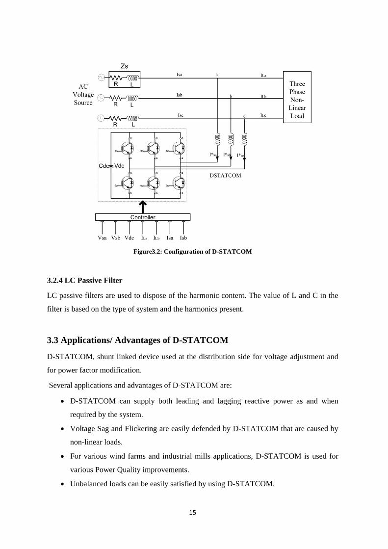
Figure3.2: Configuration of D-STATCOM
3.2.4 LC Passive Filter
LC passive filters are used to dispose of the harmonic content. The value of L and C in the
filter is based on the type of system and the harmonics present.
3.3 Applications/ Advantages of D-STATCOM
D-STATCOM, shunt linked device used at the distribution side for voltage adjustment and
for power factor modification.
Several applications and advantages of D-STATCOM are:
D-STATCOM can supply both leading and lagging reactive power as and when
required by the system.
Voltage Sag and Flickering are easily defended by D-STATCOM that are caused by
non-linear loads.
For various wind farms and industrial mills applications, D-STATCOM is used for
various Power Quality improvements.
Unbalanced loads can be easily satisfied by using D-STATCOM.

16
D-STATCOM has high efficiency and can provide single phase control for
unbalanced load.
D-STATCOM allows continuous and dynamic voltage control and full grid control.
3.4 Control Strategy for D-STATCOM- SRF Theory
D-STATCOM is employed for harmonic easing; reactive power compensation or load
balancing at the distribution end of the network. Different control theories or algorithms are
used for extracting reference source currents. Some of the strategies SRF theory, IPR theory,
Adaline Based algorithm, DC bus regulation for current compensation and some schemes
based on artificial intelligence. Amongst from these schemes, SRF based theory is used to
study the performance of the DSATCOM with Field Oriented Control (FOC) induction motor
drive as a non-linear load is examined.
Synchronous Reference Frame (SRF) Theory
SRF theory, a d-q control theory is based on the conversion of 3 phase current frame a-
b-cto synchronously rotating d-q frame. Schematicplan of SRF theory is explained in
Figure3.3. To the Phase Locked Loop (PLL) block, voltage signals Va, Vb and Vc are
applied to obtain sine and cosine signals.
Load current signals ILa, ILb and ILc are converted from 3 phase quantities to 2 phase
quantities i.e Iα and Iβ with the help of Clark’s transformation following the equations:
𝑰𝜶𝑰𝜷
= 𝟐
𝟑 𝟏 −
𝟏
𝟐−
𝟏
𝟐
𝟎 𝟑
𝟐−
𝟑
𝟐
𝑰𝑳𝒂𝑰𝑳𝒃𝑰𝑳𝒄
(2)
𝑽𝜶
𝑽𝜷 =
𝟐
𝟑 𝟏 −
𝟏
𝟐−
𝟏
𝟐
𝟎 𝟑
𝟐−
𝟑
𝟐
𝑽𝒂
𝑽𝒃
𝑽𝒄
(1)

17
Figure3.3:Schematicplan of SRF based theory
Park’s transformation is used for converting balanced two-phase stationary quantities to 2-
phase rotating reference frame. The 2-phase stationary quantities i.e Iαand Iβ are
perpendicular to each other and two-phase rotating reference frame quantities i.e. Idand Iq.
Idis rotated at a rotation angel θ to the α axis whereas Iq remains perpendicular to Idaxis. The
reference frames are shown in the Figure3.4.
Figure 3.4: Reference Frames
After Clark’s Transformation, Park’s Transformation is done by using the following
equation:
𝑰𝒅𝑰𝒒
= 𝒄𝒐𝒔𝜽 𝒔𝒊𝒏𝜽−𝒔𝒊𝒏𝜽 𝒄𝒐𝒔𝜽
𝑰𝜶𝑰𝜷
(3)

18
For extraction the DC component from the synchronously rotated currents, Low pass filter is
used. These extracted DC currents are altered back into IαDC and IβDCusing Reverse Park’s
Transformation equation:
𝑰𝜶𝒅𝒄
𝑰𝜷𝒅𝒄 =
𝒄𝒐𝒔𝜽 𝒔𝒊𝒏𝜽−𝒔𝒊𝒏𝜽 𝒄𝒐𝒔𝜽
𝑰𝒅𝒅𝒄
𝑰𝒒𝒅𝒄 (4)
Reverse Clark’s Transformation is applied to obtain 3-phase Reference Source Currents
I*
sa, I*sb and I
*sc from the derived DCcurrents using the equation:
𝑰𝒔𝒂∗
𝑰𝒔𝒃∗
𝑰𝒔𝒄∗ =
𝟐
𝟑
𝟏
𝟐𝟏 𝟎
𝟏
𝟐−
𝟏
𝟐
𝟑
𝟐
𝟏
𝟐−
𝟏
𝟐−
𝟑
𝟐
𝑰𝟎∗
𝑰𝜶𝒅𝒄∗
𝑰𝜷𝒅𝒄∗
(5)
PWM controller is employed for the comparison of Reference Source Currents and the
actual source currentsand the derived gating signals are applied to the gates of Voltage
Source Inverter.

19
Chapter- 4
Multilevel Converters
4.1 Introduction
Converter is a conversion device used to alter the nature of electric supply i.e. from DC to AC
and vice-versa, DC to DC as well as AC to AC. As a rectifier, AC input to DC output
conversion is done. As an inverter, it converts DC input to AC output. As a chopper, DC to
DC conversion is there and as a cyclo converter, AC to AC conversion is there.
Voltage source inverters (VSI) are basically two-level inverters. By increasing the switching
frequency of VSI, better output voltage waveform can be obtained. Various PWM switching
strategies are used to control harmonics in VSI.
Figure 4.1 shows the Flowchart for High Power Factor Converters.
Figure 4.1: Flowchart for High Power Factor Converters
In the year 1975, the concept of Multilevel inverters was introduced. Basically, Multilevel
inverter began with 3 level inverter.Multilevel inverters are fundamentally used to obtain
sinusoidal voltage from several levels of voltage extracting input current with very low

20
distortion operating at lower switching frequency; generate smaller torque ripples in the
motor. These can generate output voltages with mature medium-power semi conductor
technology with lower distortion. The output waveforms access a more sinusoidal wave with
a reduced harmonic distortion when numbers of level are increased.
Multilevel inverters havereplaced the conventional VSIs because it is difficult to use
conventional VSIs in high voltage appliances due to their high device rating constraints and
increased switching losses. Also, the series/parallel combination of devices is a great problem.
The basic topology of the Multilevel inverter is toobtain a more sinusoidal voltage waveform
from several level ofvoltages. The unique structure of MLI allows them to attain more
number of voltage levels with lower harmonics without using a transformer or Series-
linkedSynchronized Switching devices.
Basically Multilevel Inverters are used for Static VAR compensators, for Adjustable Speed
Drives (ASD), back to back high voltages inter tie and many more.
A disadvantage of Multilevel inverter is the constraint of more number of power
semiconductor switches. Though the switches used in MLIs are of low voltage rating but
every switch involve a separate gate drive circuit which however makes the whole system
more expensive with increase in the complexity.
Figure 4.2 shows the General topology for Multilevel Inverter.
Figure 4.2: General topology for Multilevel Inverter

21
4.2 Multilevel Inverters
The basic standard Multilevelinverter are:
DC-MLI
FC-MLI
Cascaded H-Bridge MLI
The brief description and basic layout of different Multilevel inverters are explained below.
4.2.1 DC-MLI: Diode-ClampedMultilevel Inverter
For p-level inverter, (p-1) capacitors are required on the DC bus.
p-level of phase voltage and (2p-1) levels of output line voltage are produced. For
example, a 5 level inverter will produce 9 level output line voltage.
In each phase, (p-1)*(p-2) number clamping diodes are required.
Blocking diodes of high-voltage rating are required.
Figure 4.3 shows the simple layout of 3 level Diode-Clamped Inverter.
Figure 4.3: 3-level Diode-ClampedMultilevel Inverter
4.2.2 FC-MLI: Flying Capacitor Multilevel Inverter
For p-level inverter, (p-1) numbers of capacitors are required at the DC bus.
Control of both real and reactive power flow can be done.
{(p-1)*(p-2)}/2 number of auxiliary capacitors are required per phase in DC bus.

22
Figure 4.4 shows the simple layout of 3 level Flying Capacitor Multilevel inverter.
Figure 4.4: 3 level Flying Capacitor Multilevel Inverter
4.2.3 Cascaded H-Bridge Multilevel Inverter
If p number of DC sources are used, (2p+1) number of output phase voltage will be
generated.
For real power conversion, separate DC sources are required.
No extra capacitor is required.
Figure 4.5 shows the simple layout of 3 level Cascaded H-Bridge Multilevel Inverter.
Figure 4.5: 3 level Cascaded H-BridgeMultilevel Inverter
In presented work, DC-MLI has been explained in detail in next section.

23
4.3DC-MLI: Diode-Clamped Multilevel Inverter
Nabae, Takahashi and Akagi put forward the first 3 levelDC-MLI in year 1981. The DC- MLI
is also acknowledged as Neutral Point Clamped (NPC) Multilevel Inverter. Without requiring
exact voltage match condition, it doubles the device voltage level.DC-MLI is basically used
for Static VAR compensation,for inter- connection of high-voltage systems, Variable speed
motor drives, mills, conveyors and so on.
For p-level inverter, at the DC bus (p-1) capacitors are requiredproducingp level of phase
voltage with (2p-1) levels of output line voltage. Blocking diodes of high voltage rating are
required for DCMLI with (p-1)*(p-2) number of clamping diodes required in each phase.
Available commercial ratings of DCMLI are 2.2 to 6.6 kV, 3.7 to44MVA.
For our work, Simulation of 7-level DC-MLI is implemented on MATLAB/Simulink
R2015b. Simulation of 7-level DC-MLI is shown in Figure 4.6.
Figure 4.6: Simulation of 7- level Diode-Clamped MLI
Output levels of a 7 level Diode-Clamped MLI are +3VDC, +2VDC,+VDC, 0, -VDC, -2VDC, -
3VDC.. DC-MLI topology is one of the generally used topology because of its high voltage
levels and high efficient operation.
24
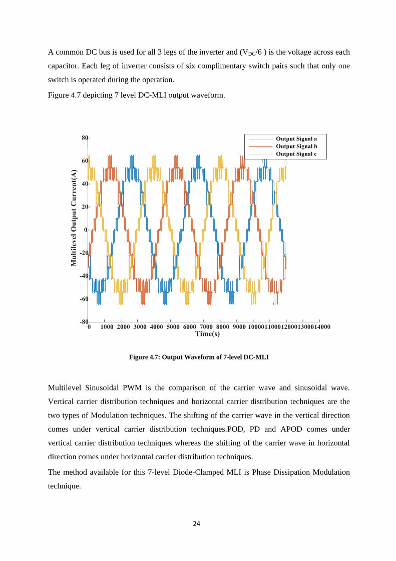
A common DC bus is used for all 3 legs of the inverter and (VDC/6 ) is the voltage across each
capacitor. Each leg of inverter consists of six complimentary switch pairs such that only one
switch is operated during the operation.
Figure 4.7 depicting 7 level DC-MLI output waveform.
Figure 4.7: Output Waveform of 7-level DC-MLI
Multilevel Sinusoidal PWM is the comparison of the carrier wave and sinusoidal wave.
Vertical carrier distribution techniques and horizontal carrier distribution techniques are the
two types of Modulation techniques. The shifting of the carrier wave in the vertical direction
comes under vertical carrier distribution techniques.POD, PD and APOD comes under
vertical carrier distribution techniques whereas the shifting of the carrier wave in horizontal
direction comes under horizontal carrier distribution techniques.
The method available for this 7-level Diode-Clamped MLI is Phase Dissipation Modulation
technique.

25
4.3.1 Advantages of DC-MLI
Control method for back-to-back inter tie system is simple.
Efficiency is high due to fundamental switching frequency.
Controlling of reactive power is easy.
Filter requirement is avoided as harmonic content will reduce when the number of
levels is increased.
4.3.2 Disadvantages of DC-MLI
With the increase in level, the requirement of diodes also increases.
For individual converter, real power flow control is a difficult task.
Sometimes unequal device rating and capacitor voltage unbalance also cause some
issues

26
Chapter- 5
System Test and Results
5.1 Introduction
Power Quality concern issues like Voltage Sag, transients, interruption of power supply,
Voltage Swell, harmonic distortions and many more problems are introduced into the system
owed to the usage of non-linear loads. Harmonics are injected into the power network,
distortion of voltage at the PCC, insulation failure of the machines due to the overheating and
over voltages, malfunctioning of sophisticated electronic equipment and many more problems
arise due to the deteriorated Power Supply. Conventional equipments like passive filters
including of R,L,C components are unable to solve Power Quality problems. Active Power
Filters are better than passive filters as they can be used for reactive power compensation,
flicker mitigation and unbalance compensation.
D-STATCOM, Custom Power device used for power factor correction at the distribution end.
A voltage source converterlinkedat one end and a DC capacitor linked at the other end. IGBTs
are used due to their lower switching losses and higher conduction rate. Multilevel inverters
are used to obtain sinusoidal waveform with more number of voltage levels thereby reducing
theTHD value. In this thesis, MATLAB/SIMULINK R2015b software has been used to
design the D-STATCOM model based upon dq0 transformation and a 7 level DC-MLI. This
system is analysed for an Induction Furnace Drive non-linear load under working conditions.
The SRF control technique is employed for D-STATCOM which observes the difference
between the load current and reference current. Consequently, the gating signals for
Multilevel inverter are produced.
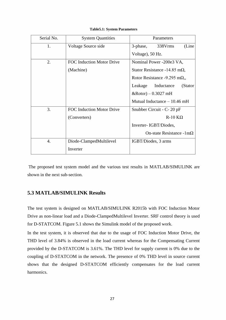
5.2 Parameters of the Test System
The proposed model system is tested for FOC induction motor drive load. The system is
equipped with 3 phase programmable voltage source with 338 Vrms, 50 Hz and a 7 level DC-
MLI is linked with the system.
Parameters of the test system are indexed in Table 5.1.
27
Table5.1: System Parameters
Serial No. System Quantities Parameters
1. Voltage Source side 3-phase, 338Vrms (Line
Voltage), 50 Hz.
2. FOC Induction Motor Drive
(Machine)
Nominal Power -200e3 VA,
Stator Resistance -14.85 mΩ,
Rotor Resistance -9.295 mΩ,,
Leakage Inductance (Stator
&Rotor) – 0.3027 mH
Mutual Inductance – 10.46 mH
3. FOC Induction Motor Drive
(Converters)
Snubber Circuit - C- 20 pF
R-10 KΩ
Inverter- IGBT/Diodes,
On-state Resistance -1mΩ
4. Diode-ClampedMultilevel
Inverter
IGBT/Diodes, 3 arms
The proposed test system model and the various test results in MATLAB/SIMULINK are
shown in the next sub-section.
5.3 MATLAB/SIMULINK Results
The test system is designed on MATLAB/SIMULINK R2015b with FOC Induction Motor
Drive as non-linear load and a Diode-ClampedMultilevel Inverter. SRF control theory is used
for D-STATCOM. Figure 5.1 shows the Simulink model of the proposed work.
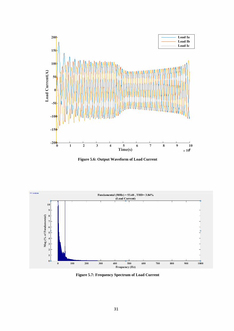
In the test system, it is observed that due to the usage of FOC Induction Motor Drive, the
THD level of 3.84% is observed in the load current whereas for the Compensating Current
provided by the D-STATCOM is 3.61%. The THD level for supply current is 0% due to the
coupling of D-STATCOM in the network. The presence of 0% THD level in source current
shows that the designed D-STATCOM efficiently compensates for the load current
harmonics.

28
Figure 5.1: MATLAB\SIMULINK of Test System
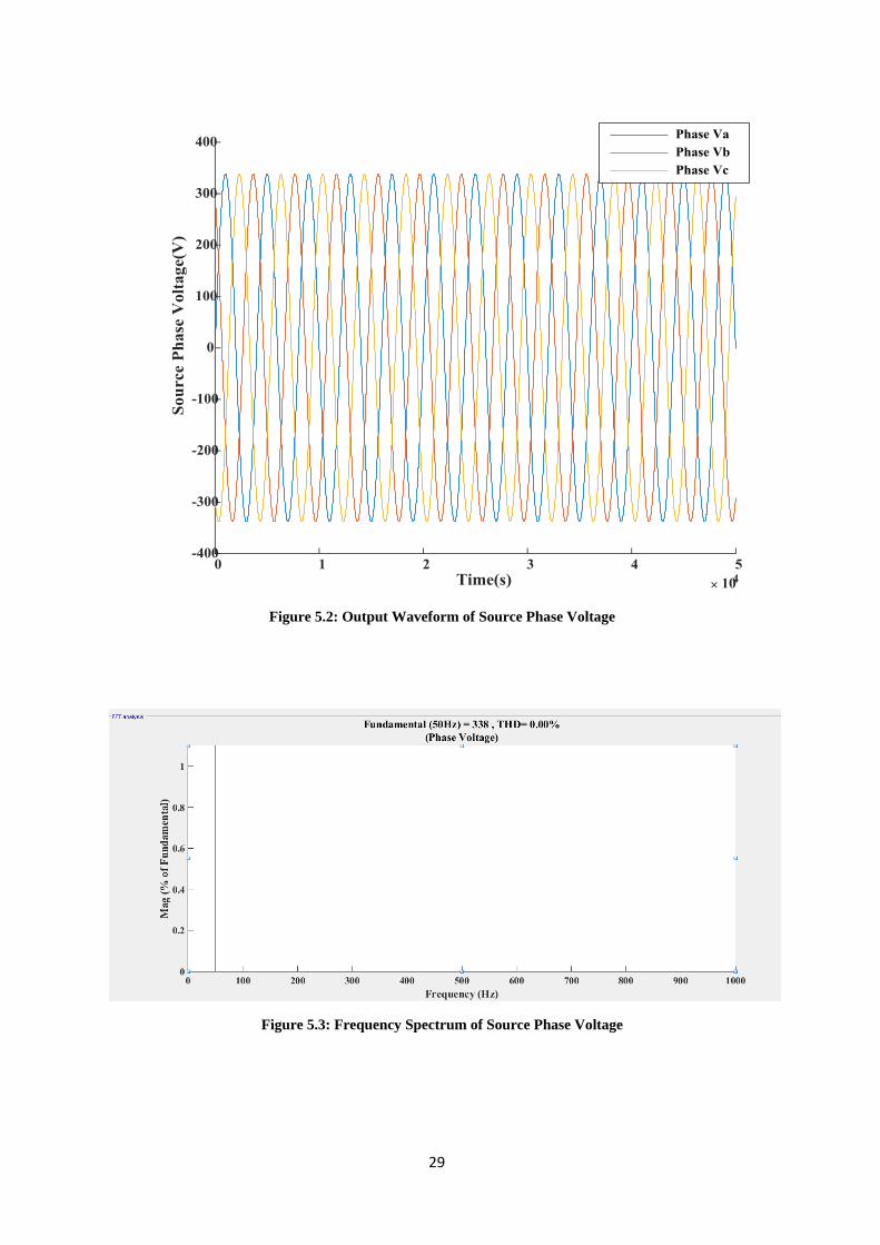
The output waveforms for source phase voltage, source current, load current and
compensating current with their FFT Analysis are shown below.
29
Figure 5.2: Output Waveform of Source Phase Voltage
Figure 5.3: Frequency Spectrum of Source Phase Voltage

30
Figure 5.4: Output Waveform of Source Current
Figure 5.5: Frequency Spectrum of Source Current
31
Figure 5.6: Output Waveform of Load Current
Figure 5.7: Frequency Spectrum of Load Current

32
Figure 5.8: Output Waveform of Compensated Current
Figure 5.9: Frequency Spectrum of Compensated Current
33
Chapter- 6
Conclusions and Future Scope
6.1 Conclusions
In the present work, Power Quality and its problems has been discussed with their
mitigation techniques. Different types of Custom Power devices are discussed in which
particularly MATLAB/SIMULINK model of D-STATCOM has been modelled and simulated
for Field Oriented Control (FOC) Induction Motor drive using the Synchronous Reference
Frame (SRF) control theory. MATLAB/SIMULINK model of 7 level DC-MLI has also been
developed. It is clearly observed from the test results that D-STATCOM efficiently eliminates
the harmonics from source current making the 0% THD level for source current. With the use
of Multilevel inverter, the output waveform is more sinusoidal with reduced harmonic
distortion. From the present work, it can be concluded that D-STATCOM finds applications
in effectively enhancing the Power Quality level at distribution side of the Power System.
6.2 Future Scope
In the present work, D-STATCOM effectively eliminates harmonic content from the load
current. Present work can be extended in the following ways:
To mitigate Power Quality problems using D-STATCOM for Renewable Energy
based distribution system.
D-STATCOM with hybrid Multipulse converter based system can be implemented.
Hybrid Multilevel inverter based D-STATCOM system can be explored.

34
References
[1] F. Martzloff and T. Gruzs, "Power Quality site surveys: facts, fiction, and
fallacies", IEEE Transactions on Industry Applications, vol. 24, no. 6, pp. 1005-
1018, 1988.
[2] D. Flinn, C. Gilker and S. Mendie, "Methods for Identifying Potential Power Quality
Problems", IEEE Cooper Power Systems, 1991.
[3] D. J. Ward, J. J. Burke and D. C. Grifith, "Power Quality-two different
perspectives", IEEE Transactions on Power Delivery, vol. 5, no. 3, pp. 1501-1513,
1990.
[4] A. Sannino, J. Svensson and T. Larsson, "Power-electronic solutions to Power Quality
problems", Electric Power Systems Research, vol. 66, no. 1, pp. 71-82, 2003.
[5] B. Singh, I. Yadav and D. Kumar, "Mitigation of Power Quality Problems Using
FACTS Controllers in an Integrated Power System Environment: A Comprehensive
Survey", International Journal of Computer Science and Artificial Intelligence, vol.
1, no. 1, pp. 1-12, 2012.
[6] A. Aigboviosa Peter, I. Kema Okakwu, E. Oluwasogo, A. Samson Alayande and A.
Airoboman, "Influence of Power Quality Problem on the Performance of an
Induction Motor", American Journal of Electrical Power and Energy Systems, vol. 4,
no. 4, p. 39, 2015.
[7] N. Rao and H. Jayatheertha, "Modeling and Simulation of D-STATCOM for Power
Quality Enhancement in Distribution System", International Journal of Engineering
Research & Technology, vol. 1, no. 5, 2012.
[8] N. Kaur, R. Sharma and J. Kaur, "Analysing the performance of D-Statcom in
mitigating transients from distribution system", International Journal of Engineering
Research and Technology, vol. 9, no. 1, pp. 17-28, 2016.
[9] B. Singh and J. Solanki, "A Comparison of Control Algorithms for D-STATCOM",
IEEE Transactions on Industrial Electronics, vol. 56, no. 7, pp. 2738-2745, 2009.
[10] E. K V and J. P, "Design and Analysis of D-STATCOM and Comparison of Various
Control Algorithms", International Journal of Innovative Research in Electrical,
Electronics, Instrumentation and Control Engineering, vol. 3, no. 1, 2016.
[11] T. Rakesh, V. Madhusudhan, and M. Sushama, "SRF Control of MLI-D-STATCOM
in Power Distribution Network", International Journal of Electrical, Electronics and

35
Computer Systems (IJEECS), vol. 4, no. 9, 2016.
[12] R. Sharma and P. Nijhawan, "Role of D-STATCOM to Improve Power Quality of
Distribution Network with FOC Induction Motor Drive as Load", International
Journal of Emerging Trends in Electrical and Electronics, vol. 5, no. 1, 2013.
[13] R. vasava, "SRF based Control for Power Quality improvement using D-
STATCOM", International Journal of Innovative and Emerging Research in
Engineering, vol. 3, no. 4, 2016.
[14] P. Nijhawan, D. Jain and R. Bhatia, "Improved performance of Multilevel inverter-
based distribution static synchronous compensator with induction furnace load", IET
Power Electronics, vol. 6, no. 9, pp. 1939-1947, 2013.
[15] M. Bansal and N. Singh Bhangu, "Reducing Harmonics Distortion in Distribution
Network Against The Induction Motor Drive Non Linear Load", International
Journal for Science and Emerging Technologies with Latest Trends, vol. 9, no. 1, pp.
27-32, 2013.
[16] A. Singh, S. Bhowmick and K. Shukla, "Load Compensation with D-STATCOM and
BESS", IEEE 5th India International Conference on. Power Electronics, 2012.
[17] K. S.Varaprasad, "Comparison and Analysis on the Role of D-STATCOM and DVR
with PI Controller to improve the Power Quality in Distributed Networks",
International Research Journal of Computer Science, vol. 1, no. 2, 2014.
[18] J. Barrena, S. Aurtenechea, J. Canales, M. Rodriguez and L. Marroyo, "Design,
analysis and comparison of Multilevel topologies for D-STATCOM applications",
European Conference on Power Electronics and Applications, 2005.
[19] B. Singh, A. Mittal, J. Gupta and B. Singh, "Application of D-STATCOM for
Mitigation of Voltage Sag for Motor Loads in Isolated Distribution Systems", IEEE
International Symposium on Industrial Electronics, vol. 3, pp. 1806-1811, 2006.
[20] L. Tolbert, Fang Zheng Peng and T. Habetler, "Multilevel converters for large electric
drives", IEEE Transactions on Industry Applications, vol. 35, no. 1, pp. 36-44, 1999.
[21] S. Iyer, A. Ghosh and A. Joshi, "Inverter topologies for D-STATCOM applications—
a simulation study", Electric Power Systems Research, vol. 75, no. 2-3, pp. 161-170,
2005.
[22] J. Lai and F. Peng, "Multilevel Converters - A New Breed of Power Converters",
IEEE Transactions on industry applications, vol. 32, pp. 509-517, 1996.
[23] J. Rodriguez, Jih-Sheng Lai and Fang Zheng Peng, "Multilevel inverters: a survey of

36
topologies, controls, and applications", IEEE Transactions on Industrial Electronics,
vol. 49, no. 4, pp. 724-738, 2002.
[24] T. Meynard, M. Fadel and N. Aouda, "Modeling of Multilevel converters", IEEE
Transactions on Industrial Electronics, vol. 44, no. 3, pp. 356-364, 1997.
[25] C. Rech, H. Pinheiro, H. Griindling, H. L. Hey and J. R. Pinheiro, "Analysis and
Comparison of Hybrid Multilevel Voltage Source Inverters", IEEE 33rd Annual
Power Electronics Specialists Conference, vol. 2, pp. 491-496, 2002.
[26] H. Chiang, B. Lin, K. Yang and C. Yang, "Analysis and Implementation of a NPC-
Based D-STATCOM under the Abnormal Voltage Conditions", IEEE International
Conference on Industrial Technology, pp. 665-670, 2005.
[27] I. Colak, E. Kabalci and R. Bayindir, "Review of Multilevel voltage source inverter
topologies and control schemes", Energy Conversion and Management, vol. 52, no.
2, pp. 1114-1128, 2011.
[28] C. Gomath, Navyanagath, S. Purnima and S. Veerakumar, "Comparison of PWM
Methods for Multilevel Inverter", International Journal of Advanced Research in
Electrical, Electronics and Instrumentation Engineering, vol. 2, no. 12, 2013.
[29] A. Nami, F. Zare, G. Ledwich, A. Ghosh and F. Blaabjerg, "Comparison between
Symmetrical and Asymmetrical Single Phase Multilevel Inverter with Diode-
Clamped Topology", IEEE Power Electronics Specialists Conference, pp. 2921-
2926, 2008.
[30] S. Fazel, S. Bernet, D. Krug and K. Jalili, ―design and Comparison of 4-kV Neutral-
Point-Clamped, Flying Capacitor, and Series-connected H-Bridge Multilevel
Converters‖, IEEE Transactions on Industry Applications, vol. 43, no. 4, pp. 1032-
1040,2007.