rohm dc/dc designer user's guide · rohm dc/dc designer user's guide content 1. what is...
TRANSCRIPT
1/17 www.rohm.com 12.Apr.2016 Rev.001© 2016 ROHM Co., Ltd. All rights reserved.
Online Design Tool of ROHM
ROHM DC/DC Designer User's Guide
Content 1. What is ROHM DC/DC Designer?
1.1 Outline 1.2 Applicable products 1.3 System Requirements 1.4 Notes 1.5 Questions/Comments
2. Access Method
2.1 Via ROHM’s top homepage (http://www.rohm.com/web/global/) 2.2 Via the individual product page 2.3 Via parametric search page of switching regulator products
3. Usage Instructions
3.1 Activating the ROHM DC/DC Designer 3.2 User Interface Description
3.2.1 Setting Parameters 3.2.2 Steady State 3.2.3 Loop Response 3.2.4 Load Transient 3.2.5 Efficiency 3.2.6 Download Design
3.3 Design Flow 3.3.1 Step1 : Input power supply specifications 3.3.2 Step2 : Input external component values 3.3.3 Step3 : Change conditions 3.3.4 Step4 : Run simulation 3.3.5 Step5 : Confirmation of "Steady State" 3.3.6 Step5 : Confirmation of "Loop Response" 3.3.7 Step5 : Confirmation of "Load Transient" 3.3.8 Step5 : Confirmation of "Efficiency" 3.3.9 Step6 : Output design report
3.4 Other functions 3.4.1 Reset function 3.4.2 Multi-output model
4. Troubleshooting 5. Disclaimer
6. Additional Notes 7. Revision History

Design Support Document
2/17 www.rohm.com 12.Apr.2016 Rev.001© 2016 ROHM Co., Ltd. All rights reserved.
ROHM DC/DC Designer User’s Guide
1. What is ROHM DC/DC Designer? 1.1 General Description
Use the online design tool "ROHM DC/DC Designer" to easily simulate the application circuit on the Web before actual parts evaluation. You can confirm the basic characteristics such as efficiency, loop stability and transient response by only 3 steps You can freely change the constant and the input signal of external parts; it can significantly reduce the time of IC and parts selection.
1.2 Applicable Products
・Switching regulator with built-in FET ・Switching regulator controller for external high current FET
1.3 System Requirements
The following environment is necessary to operate ROHM DC/DC Designer.
・Adobe Reader® ・Microsoft® Silverlight®
This tool can’t be run on Microsoft Silverlight unsupported browser. Confirm in the following "System Requirements" URL for browser compatibility of this tool. (https://www.microsoft.com/getsilverlight/get-started/install/default.aspx?reason=unsupportedbrowser&_helpmsg=ChromeVersionDoesNotSupportPlugins&v=4.0.50826.0#") Please note that you cannot use the latest version of "Google Chrome™". "Internet Explorer®" is the recommended browser to use this tool.
Trademarks: Adobe Reader® is a registered trademark of Adobe Systems Incorporated in the United States and other countries. Microsoft® Silverlight® and Internet Explorer® are registered trademarks of Microsoft Corporation in the United States
and other countries. Google Chrome™ is a trademark of Google Inc.
1.4 Notes
Before using ROHM DC/DC Designer, please confirm that you have read the disclaimer. The results provided by ROHM DC/DC Designer are based on experimental results using ROHM evaluation
boards and cannot be guaranteed. In addition, ROHM DC/DC Designer offers reference results, not guaranteed results.
Please note the characteristics of external parts. ROHM DC/DC Designer specifications are subject to change without notice.
1.5 Questions/Comments
For inquiries and/or comments, please contact us at: https://www.rohm.com/web/global/contactus

Design Support Document
3/17 www.rohm.com 12.Apr.2016 Rev.001© 2016 ROHM Co., Ltd. All rights reserved.
ROHM DC/DC Designer User’s Guide
2. Access method The following are three methods to access ROHM DC/DC Designer. Via ROHM’s homepage (http://www.rohm.com) Via the individual product page Via parametric search page of switching regulator products (http://www.rohm.com/web/global/search/parametric/-
/search/Switching%20Regulators) 2.1 Via ROHM’s homepage
■ TOP of the homepage
■ Power management / power supply IC page (switching regulator)
■Parametric Search of Switching Regulator
(http://www.rohm.com/web/global/search/parametric/-/search/Switching%20Regulators) ROHM DC/DC Designer corresponding to the individual product activates by clicking the "D button".
Power Management
Switching Regulator
Design Support Document
4/17 www.rohm.com 12.Apr.2016 Rev.001© 2016 ROHM Co., Ltd. All rights reserved.
ROHM DC/DC Designer User’s Guide
3. Usage Instructions 3.1 Activating the ROHM DC/DC Designer
A new window opens when you activate the ROHM DC/DC Designer, and the simulation result on the basic application condition is displayed. A recommended circuit is displayed in the initial display. This display can be changed to show each characteristic data by using the Function button.
3.2 User interface description
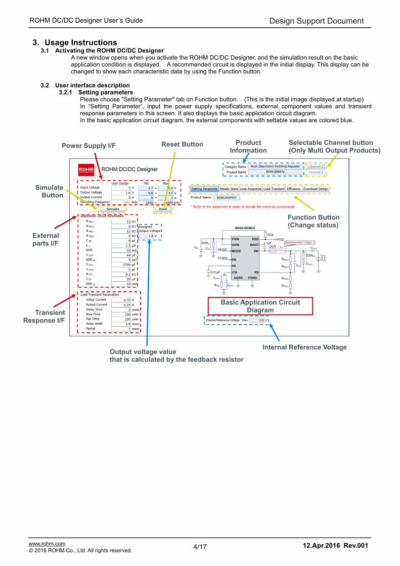
3.2.1 Setting parameters Please choose "Setting Parameter" tab on Function button. (This is the initial image displayed at startup) In “Setting Parameter”, input the power supply specifications, external component values and transient response parameters in this screen. It also displays the basic application circuit diagram. In the basic application circuit diagram, the external components with settable values are colored blue.
Product Information
Power Supply I/F
Simulate Button
Reset Button
External parts I/F
Internal Reference Voltage Output voltage value that is calculated by the feedback resistor
Selectable Channel button (Only Multi Output Products)
Transient Response I/F
Function Button (Change status)
Basic Application Circuit Diagram
Design Support Document
5/17 www.rohm.com 12.Apr.2016 Rev.001© 2016 ROHM Co., Ltd. All rights reserved.
ROHM DC/DC Designer User’s Guide
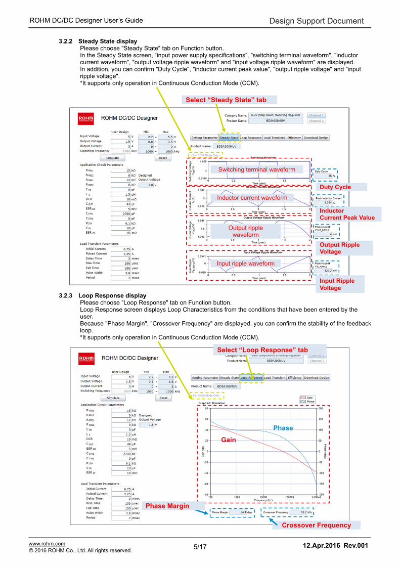
3.2.2 Steady State display Please choose "Steady State" tab on Function button. In the Steady State screen, “input power supply specifications”, "switching terminal waveform", "inductor current waveform", "output voltage ripple waveform" and "input voltage ripple waveform" are displayed. In addition, you can confirm "Duty Cycle", "inductor current peak value", "output ripple voltage" and "input ripple voltage". *It supports only operation in Continuous Conduction Mode (CCM).
3.2.3 Loop Response display Please choose "Loop Response" tab on Function button. Loop Response screen displays Loop Characteristics from the conditions that have been entered by the user. Because "Phase Margin", "Crossover Frequency" are displayed, you can confirm the stability of the feedback loop. *It supports only operation in Continuous Conduction Mode (CCM).
Select “Steady State” tab
Duty Cycle
InductorCurrent Peak Value
Output Ripple Voltage
Input Ripple Voltage
Switching terminal waveform
Inductor current waveform
Output ripple waveform
Input ripple waveform
Select “Loop Response” tab
Phase Margin
Crossover Frequency
Gain
Phase
Design Support Document
6/17 www.rohm.com 12.Apr.2016 Rev.001© 2016 ROHM Co., Ltd. All rights reserved.
ROHM DC/DC Designer User’s Guide
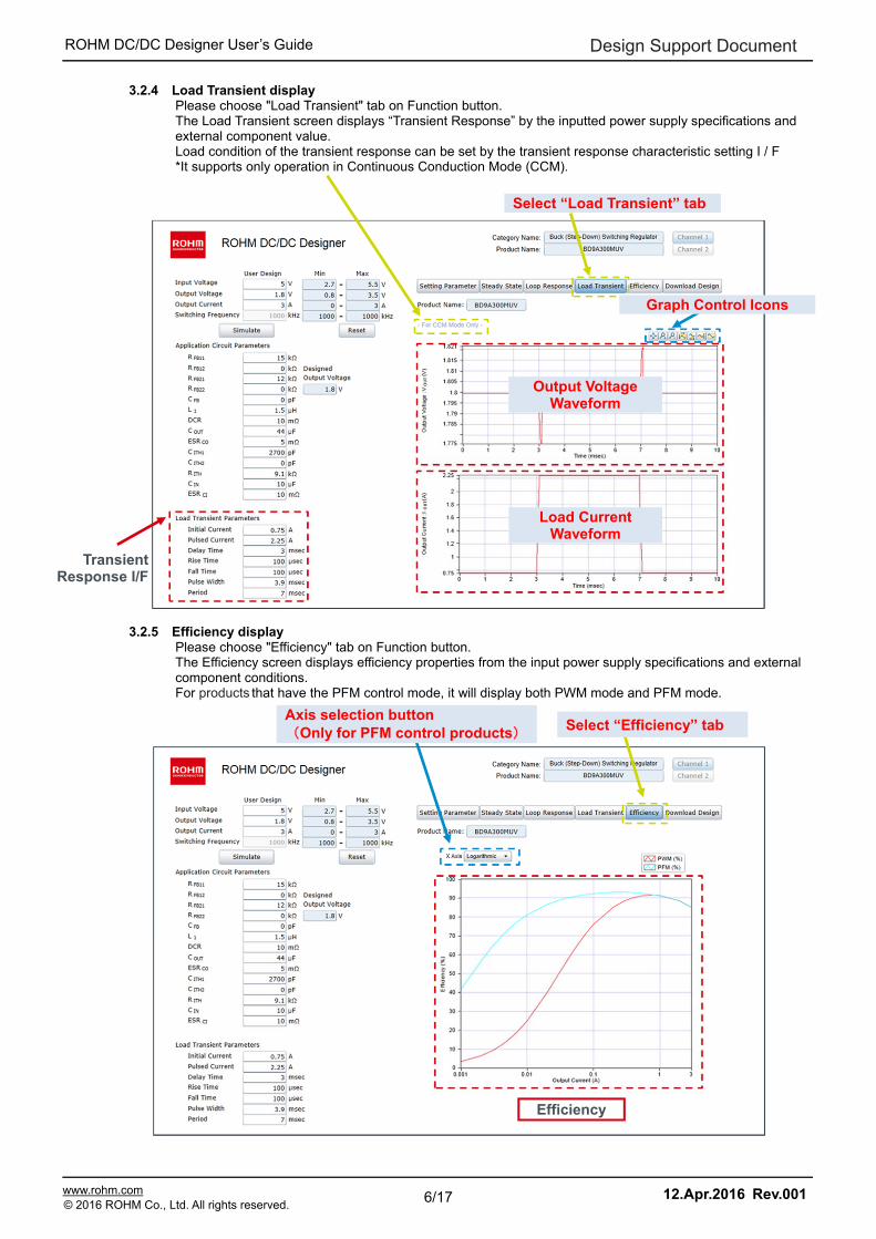
3.2.4 Load Transient display Please choose "Load Transient" tab on Function button. The Load Transient screen displays “Transient Response” by the inputted power supply specifications and external component value. Load condition of the transient response can be set by the transient response characteristic setting I / F *It supports only operation in Continuous Conduction Mode (CCM).
3.2.5 Efficiency display Please choose "Efficiency" tab on Function button. The Efficiency screen displays efficiency properties from the input power supply specifications and external component conditions. For products that have the PFM control mode, it will display both PWM mode and PFM mode.
Load Current Waveform
Select “Load Transient” tab
Graph Control Icons
Output Voltage Waveform
Transient Response I/F
Select “Efficiency” tab Axis selection button (Only for PFM control products)
Efficiency

Design Support Document
7/17 www.rohm.com 12.Apr.2016 Rev.001© 2016 ROHM Co., Ltd. All rights reserved.
ROHM DC/DC Designer User’s Guide
3.2.6 Download Design display Please choose "Download Design" tab on Function button. Please wait while each output display result is saved. The Design Report (PDF file) is ready for download after a filename is displayed. Please click the "Download" button to download it.
■Design Report example (Ex.BD9A300MUV)
Download Button
Disclaimer
Select “Download Design” tab Design Report File Name

Design Support Document
8/17 www.rohm.com 12.Apr.2016 Rev.001© 2016 ROHM Co., Ltd. All rights reserved.
ROHM DC/DC Designer User’s Guide
3.3 Design Flow The basic design flow are as follows:
3.3.1 STEP1: Input power supply specifications Please input power supply conditions (input voltage, output voltage and output current). For products that can change the switching frequency, input the switching frequency.
Step 1 • Input Power Supply Specifications
Step 2 • Input External Components Values
Step 3 • Change Conditions (This step can be skipped)
Step 4• Run Simulation
Step 5 • Check Simulation Result
Step 6 • Output Design Report (This step can be skipped)
Displays the product specific values STEP1
The value of RFB11, RFB12, RFB21 and RFB22 are automatically changed depending on the inputted “Output Voltage”.
This message is displayed when setting has been changed
Power Supply I/F
Design Support Document
9/17 www.rohm.com 12.Apr.2016 Rev.001© 2016 ROHM Co., Ltd. All rights reserved.
ROHM DC/DC Designer User’s Guide
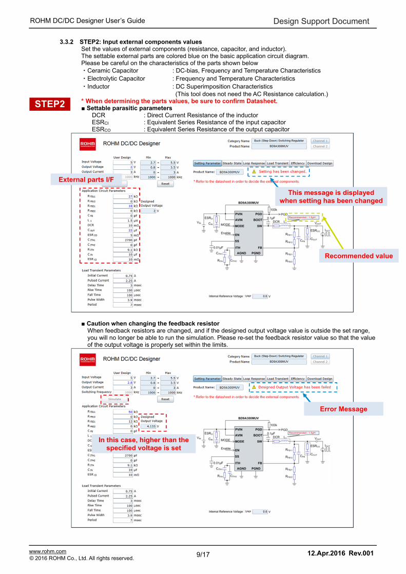
3.3.2 STEP2: Input external components values Set the values of external components (resistance, capacitor, and inductor). The settable external parts are colored blue on the basic application circuit diagram. Please be careful on the characteristics of the parts shown below ・Ceramic Capacitor : DC-bias, Frequency and Temperature Characteristics ・Electrolytic Capacitor : Frequency and Temperature Characteristics ・Inductor : DC Superimposition Characteristics
(This tool does not need the AC Resistance calculation.) * When determining the parts values, be sure to confirm Datasheet. ■ Settable parasitic parameters
DCR : Direct Current Resistance of the inductor ESRCI : Equivalent Series Resistance of the input capacitor ESRCO : Equivalent Series Resistance of the output capacitor
■ Caution when changing the feedback resistor
When feedback resistors are changed, and if the designed output voltage value is outside the set range, you will no longer be able to run the simulation. Please re-set the feedback resistor value so that the value of the output voltage is properly set within the limits.
STEP2
External parts I/F
This message is displayed when setting has been changed
Recommended value
Error Message
In this case, higher than the specified voltage is set
Design Support Document
10/17 www.rohm.com 12.Apr.2016 Rev.001© 2016 ROHM Co., Ltd. All rights reserved.
ROHM DC/DC Designer User’s Guide
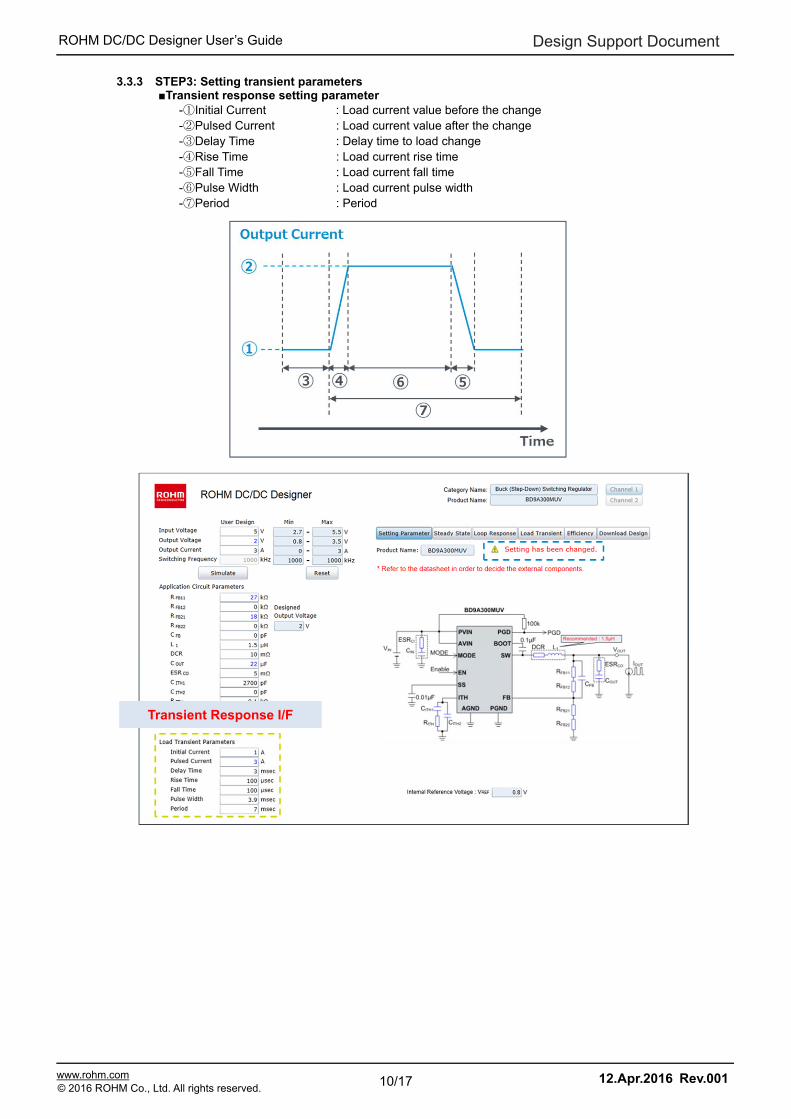
3.3.3 STEP3: Setting transient parameters ■Transient response setting parameter
-①Initial Current : Load current value before the change -②Pulsed Current : Load current value after the change -③Delay Time : Delay time to load change -④Rise Time : Load current rise time -⑤Fall Time : Load current fall time -⑥Pulse Width : Load current pulse width -⑦Period : Period
Transient Response I/F

Design Support Document
11/17 www.rohm.com 12.Apr.2016 Rev.001© 2016 ROHM Co., Ltd. All rights reserved.
ROHM DC/DC Designer User’s Guide
3.3.4 STEP4: Run simulation Start by clicking “Simulate” button.
3.3.5 STEP5: Confirm "Steady State" result
In "Steady State" screen, it is possible to confirm the "switching waveform", "inductor current waveform", "output ripple waveform" and "input ripple waveform". ■ Check Point Make sure that the inductor saturation current is greater than or equal to the peak current. The confirmation of output ripple voltage and input ripple voltage is possible, too.
Check
Check
Peak current < Saturation current Check
Output ripple
Input ripple

Design Support Document
12/17 www.rohm.com 12.Apr.2016 Rev.001© 2016 ROHM Co., Ltd. All rights reserved.
ROHM DC/DC Designer User’s Guide
3.3.6 STEP5: Confirm "Loop Response" result In "Loop Response" screen, confirm the stability of the feedback loop and decide setting values of external parts. * The resulting output from this tool will not be exact because there is a difference between the parameters of this tool and the actual parts parameters such as parasitic characteristics that depend on PCB and implementation condition. In order to confirm the stability and response of the system, creating an actual prototype is needed ■Check Point The system is required to have a phase margin of more than 45deg. (it is the phase at 0dB). It is an indicator of the feedback loop stability. Next, the crossover frequency is set to less than 1/10 of the switching frequency. When the phase margin is small, there is a possibility that the output voltage has abnormal oscillation. In that case, adjust the phase compensation constant (RITH, CITH) to establish both stability and good transient response of the feedback loop. (Click "Load Transient" button to confirm the transient response characteristics.)
Check Check
Phase margin > 45deg Crossover frequency < 0.1(fOSC)
Design Support Document
13/17 www.rohm.com 12.Apr.2016 Rev.001© 2016 ROHM Co., Ltd. All rights reserved.
ROHM DC/DC Designer User’s Guide
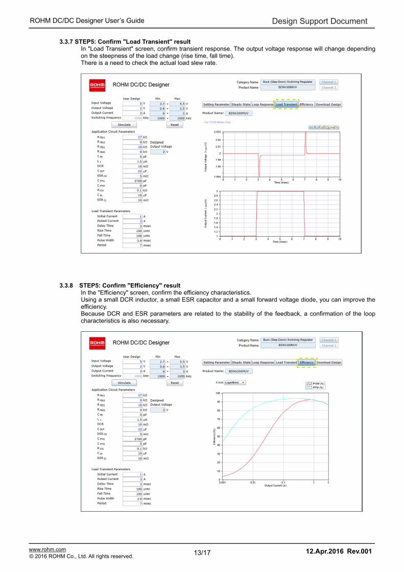
3.3.7 STEP5: Confirm "Load Transient" result In "Load Transient" screen, confirm transient response. The output voltage response will change depending on the steepness of the load change (rise time, fall time). There is a need to check the actual load slew rate.
3.3.8 STEP5: Confirm "Efficiency" result
In the "Efficiency" screen, confirm the efficiency characteristics. Using a small DCR inductor, a small ESR capacitor and a small forward voltage diode, you can improve the efficiency. Because DCR and ESR parameters are related to the stability of the feedback, a confirmation of the loop characteristics is also necessary.
Design Support Document
14/17 www.rohm.com 12.Apr.2016 Rev.001© 2016 ROHM Co., Ltd. All rights reserved.
ROHM DC/DC Designer User’s Guide
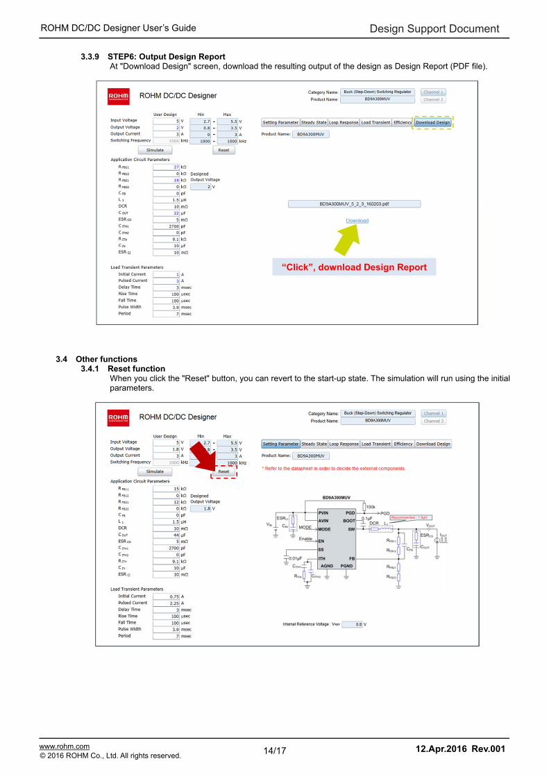
3.3.9 STEP6: Output Design Report At "Download Design" screen, download the resulting output of the design as Design Report (PDF file).
3.4 Other functions 3.4.1 Reset function
When you click the "Reset" button, you can revert to the start-up state. The simulation will run using the initial parameters.
“Click”, download Design Report
Design Support Document
15/17 www.rohm.com 12.Apr.2016 Rev.001© 2016 ROHM Co., Ltd. All rights reserved.
ROHM DC/DC Designer User’s Guide
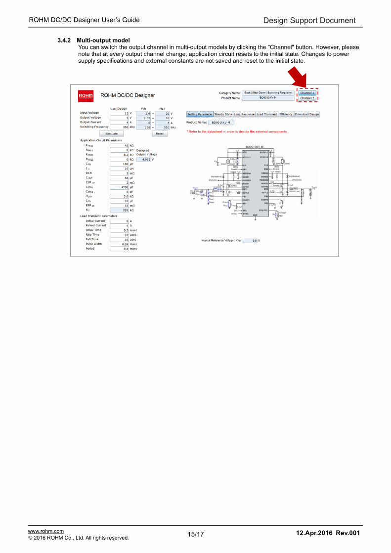
3.4.2 Multi-output model You can switch the output channel in multi-output models by clicking the "Channel" button. However, please note that at every output channel change, application circuit resets to the initial state. Changes to power supply specifications and external constants are not saved and reset to the initial state.
Design Support Document
16/17 www.rohm.com 12.Apr.2016 Rev.001© 2016 ROHM Co., Ltd. All rights reserved.
ROHM DC/DC Designer User’s Guide
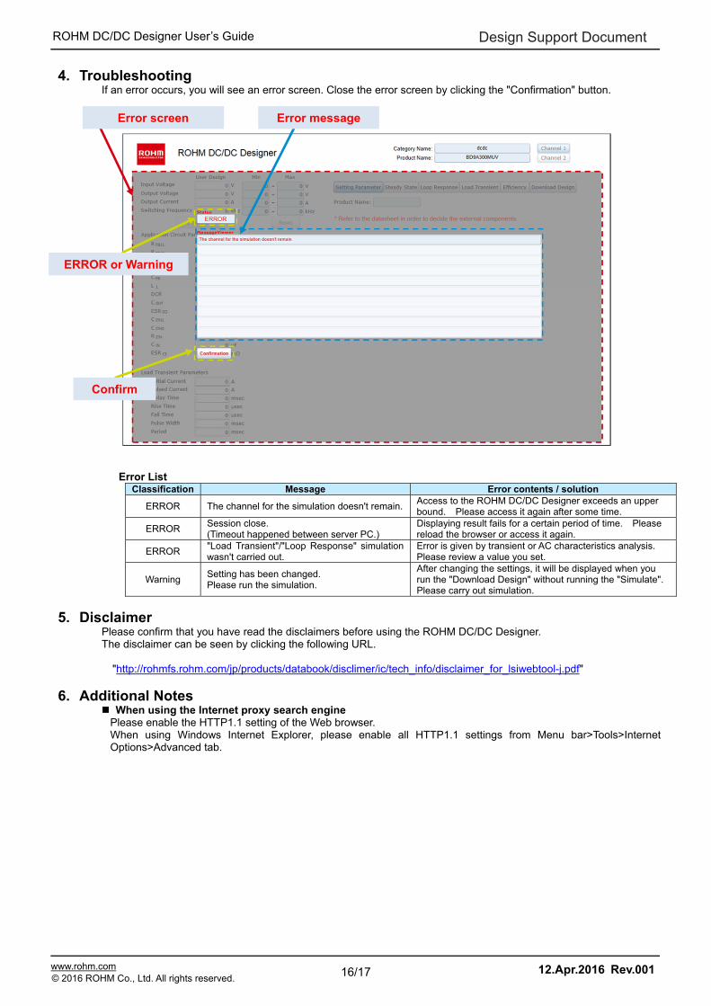
4. Troubleshooting If an error occurs, you will see an error screen. Close the error screen by clicking the "Confirmation" button.
Error List Classification Message Error contents / solution
ERROR The channel for the simulation doesn't remain.Access to the ROHM DC/DC Designer exceeds an upper bound. Please access it again after some time.
ERROR Session close. (Timeout happened between server PC.)
Displaying result fails for a certain period of time. Please reload the browser or access it again.
ERROR "Load Transient"/"Loop Response" simulation wasn't carried out.
Error is given by transient or AC characteristics analysis. Please review a value you set.
Warning Setting has been changed. Please run the simulation.
After changing the settings, it will be displayed when you run the "Download Design" without running the "Simulate". Please carry out simulation.
5. Disclaimer Please confirm that you have read the disclaimers before using the ROHM DC/DC Designer. The disclaimer can be seen by clicking the following URL.
"http://rohmfs.rohm.com/jp/products/databook/disclimer/ic/tech_info/disclaimer_for_lsiwebtool-j.pdf"
6. Additional Notes When using the Internet proxy search engine
Please enable the HTTP1.1 setting of the Web browser. When using Windows Internet Explorer, please enable all HTTP1.1 settings from Menu bar>Tools>Internet Options>Advanced tab.
Error screen Error message
ERROR or Warning
Confirm
Design Support Document
17/17 www.rohm.com 12.Apr.2016 Rev.001© 2016 ROHM Co., Ltd. All rights reserved.
ROHM DC/DC Designer User’s Guide
7. Revision History
Date Revision Changes
12.Apl.2016 001 New release