rodin deliverable d4 traceable requirements …rodin.cs.ncl.ac.uk/deliverables/d4.pdf · traceable...
TRANSCRIPT
Project IST-511599
RODIN “Rigorous Open Development Environment for Complex Systems”
RODIN Deliverable D4
Traceable Requirements Document for Case Studies
Budi Arief (University of Newcastle upon Tyne, UK), Joey Coleman (University of Newcastle upon Tyne, UK), Anthony Hall (affiliated with Praxis High Integrity Systems, UK), Adrian Hilton (Praxis High Integrity Systems, UK) , Alex Iliasov (University of Newcastle upon Tyne, UK), Ian Johnson (VT Engine Controls Ltd, UK), Cliff Jones (University of Newcastle upon Tyne, UK), Linas Laibinis (Aabo Akademi University, Finland), Sari Leppänen (Nokia, Finland), Ian Oliver (Nokia, Finland), Alexander Romanovsky (University of Newcastle upon Tyne, UK), Colin Snook (University of Southampton, UK), Elena Troubitsyna (Aabo Akademi University, Finland), Jurgen Ziegler (Nokia, Finland)
Public Document
28 February 2005
http://rodin.cs.ncl.ac.uk/
Contents 1 Introduction…………………………………………………………………………….. 1 2 Requirements Document for Case Study 1: Formal Approaches in Protocol
Engineering……..………………………………………………………………………. 5
3 Requirements Document for Case Study 2: Engine Failure Management System …… 26 4 Requirements Document for Case Study 3: MITA End-to-end Architecture
Requirements…………………………………………………………………………… 53
5 Requirements for Case study 4……………………...………………………………… 70 6 Requirements Document for Case study 5: Ambient Campus – the Lecture
Scenario………………………………………………………........................................ 125

SECTION1. INTRODUCTION This document presents the results of the requirements elicitation and analysis conducted for the case studies in RODIN. Usually these processes lead to creating requirements specification – a document serving as a contract between customers and developers of a system. The term requirements specification has a very broad meaning: it might be a document written in plain English, a graphical model, a formal mathematical model, a collection of scenarios or prototypes, or any combination of these. Usually a written document (we call it the requirements document) combining natural language descriptions and graphical models is considered to be the most suitable style to describe the requirements for large systems. The requirements document in such a style has been created by J.-R. Abrial in the process of formal development of controlling software for industrial press [1.1]. The development started from writing the requirements document and the reference document. The requirements document essentially consisted of explanatory text in plain English, diagrams illustrating system functionality and requirements definitions. The requirements were arranged according to a certain taxonomy and indexed. The taxonomy was used to structure the requirements according to various views on system behaviour. The indexes helped in referencing and tracing the requirements in the development process. The reference document contained only the requirements definitions extracted from the requirements document. These documents were found indispensable in the formal development of the system. They were used to eliminate requirement ambiguities, create formal specifications and validate overall system design. The success of this system development has motivated the project members to adopt such a document style while creating the requirements documents for the RODIN case studies. The experience in creating requirements documents and formal system development in the Event-B framework was shared by J-R.Abrial at the tutorial given for participants of RODIN in the beginning of December 2004. As a result, the requirements documents for three case studies are written following Abrial’s approach. The requirements document for case study 1 – Formal Approaches to Protocol Engineering – is presented in Section 2 of this deliverable. The document has been created from several sources: informal official requirements on 3GPP Positioning System, a set of UML models describing the positioning service, and documents on the Lyra development method. The requirements document adopts Abrial’s style. Our next steps will be to develop formal specification of 3GPP Positioning System by applying formal modelling techniques of the B Method. We are also planning to apply general refinement/decomposition techniques to be developed in WP2, and investigate applicability of formal reasoning techniques for fault tolerance in the area of telecommunications. Section 3 contains requirements document for case study 2 – Engine Failure Management System. The work on this document has explored the use of models in requirements with a view to making a specification generic and providing instances of the generic specification. We have also experimented with the expression and integration of
1

requirements using UML. The current plan is to continue work in requirement engineering with our academic partner to gain insights into providing a well formed specification. A formal UML-B model will be developed from the requirement work. The work is expected to progress by developing the link with UML_B and the design issues it raises and demands it might impose on the methodology. The requirements specification for case study 2 is novel in that it presents the functional requirements of the case as generic and traces the requirement to parameterised tables of an application. The specification is also unique in that it expresses the taxonomy of requirements and their relationships in a UML diagram style. This will assist in developing the generic model in line with the UML_B approach adopted for the case study. The modelling and verification of the generic requirement from parameterised tables provides a particular focus to drive development of the ProB tool and UML_B approach and presents specific challenges to scalability of an application and its effects on the tools. Unlike the previous section, Section 4 contains requirements document for case study 3 – Formal Techniques within an MDA Context – written in an unstructured manner as plain English text. As explained in this section such a style is needed to support further experimenting with requirements engineering within this case study. The role of the requirements document for case study 3 is to outline the requirements process, the plan of work and the initial set of informal (or even semi-formal) requirements for the MITA End-to-End architecture. Additional architectures will be made available during the course of the RODIN project as detailed requirements become available. The case study can be split into a number of phases:
• Construction and Formalisation of E2E Model • Construction and Formalisation of Security Model • Mapping of Security Model against E2E Model • Construction of Simple Application utilising both E2E and Security Concepts
For the E2E and Security framework modelling stages we expect a demonstration of the internal consistency of the models produced. When mapping the security model against the E2E model we will have a number of options regarding which parts of the E2E should take the responsibility for the various security related functionality. It is also conceivable that the security model and the E2E do not exactly fit - we then need to explore the ramifications of such a situation with regards to the consistencies of the E2E and security models. Finally the construction of a simple application (to be decided) that utilizes both the security and E2E frameworks will be made. Again this application itself must be internally consistent and be consistent with the architectures/frameworks employed. Section 5 contains the requirements document for case study 4 – CDIS Air Traffic Control Display System. This document is written using the proprietary format as explained in the introduction to this section. Praxis is particularly interested in understanding how well Event B supports the structuring of a large specification of the scale of the CDIS specification. For this reason it is important to cover a large part of the original high level specification in the high-level Event B specification. Taking a vertical
2

slice down through the system structure preserves the many levels of detail in the original system while keeping the subset size tractable. The original documents developed by Praxis have been reduced to the subset that forms the basis of this case study. Included here is the requirements document for our subset, presented within the original context that CDIS was built. We feel that it is important not to lose this context as we redevelop the subset of the CDIS system. Updating this document to reflect the context of RODIN CS4 is neither necessary nor desirable for the purpose of developing the case study materials to a position where they may be usefully analysed by the WP3 tool kernel and WP4 plugins. Furthermore, the original context and methods used will make for an excellent comparison against the emerging WP2 methodology. Fault tolerance issues are covered in the specification document, which is much larger than the requirements document included here. Remaining fault tolerance issues – primarily concerning delays and user error – will be examined during the redevelopment. Praxis are also interested in understanding how well Event-B refinement supports the formal development from the high-level specification to the detailed design, in particular, the introduction of distribution in the design. This relationship between the high-level specification and the detailed design was not formally established in the original development as the refinement techniques available at the time were deemed inadequate. We believe it will be sufficient to focus on the refinement of a subset of the full Event-B high-level specification to develop useful transferable results on refinement for systems like CDIS. To this end, approximately one quarter of the material will be redeveloped in Event-B notation in the near term. This will allow the experience of a fully developed project to inform the development of the RODIN methodology and notation. The initial material and remaining portions will be used to evaluate the RODIN tools as they are developed. Section 6 defines the requirements of the first scenario of case study 5 (Ambient Campus) - the Ambient Lecture scenario. This case study will investigate a number of related scenarios (see deliverable D2 for a more detailed discussion of our possible choices). This particular scenario allows us to apply and demonstrate the project results in development, modelling and verification of fault tolerant mobile asynchronous systems. While creating this scenario, we also performed some initial experimental work with a chosen coordination-based mobility middleware (Lime) and developed a novel exception-handling mechanism for applications developed in this paradigm. Next we will focus on specification of this scenario, on its formal modelling using one of the RODIN formalisms (most likely B), on application of the mobility abstractions which are under development in WP2 and on preparation of the second scenario. We are planning to apply the general refinement/decomposition techniques to be developed in WP2 and to progress further in our programming experiments. Later on we will evaluate the applicability of the process-based modelling techniques (WP2) in this case study and apply the mobility
3

plug-in (WP4) to model-check mobility-specific properties of the Ambient Campus scenarios. The requirements documents presented in these deliverable define the systems that will validate RODIN’s tools and methodologies. The documents have been created in a close co-operation between academic and industrial partners. This work has facilitated knowledge exchange, tightened co-operation and helped to achieve a common understanding of research goals. 1.2. References [1.1]. Available via http://se.inf.ethz.ch/teaching/ws2004/0271/index.html#reading
4
SECTION 2. REQUIREMENTS DOCUMENT FOR CASE STUDY 1: FORMAL APPROACHES IN PROTOCOL ENGINEERING
2.1 Introduction This case study investigates application of formal methods for development of telecommunications protocols. Telecommunications systems tend to be very large and data intensive. Such systems provide their services by co-ordinating several subservices distributed over the network. The protocol engineering group at Nokia has developed the “Lyra” method which supports the service-oriented approach to protocol engineering. The main goal of this case study is to provide support (in the form of formal techniques and tools) for various stages of this approach. The proposed tools and techniques will be validated by the development of a Position Calculation Application Part (PCAP) specified by the Third Generation Partnership Project (3GPP). PCAP is part of the User Equipment (UE) positioning system in the UMTS radio access network. PCAP is specified to manage the communication between the network elements Radio Network Controller (RNC) and Stand-alone Assisted Global Positioning System Serving Mobile Location Centre (SAS). The requirements document for PCAP is presented in this deliverable. Usually telecommunications systems are verified by using model checking techniques. However, model checking is prone to the state explosion problem, when applied to large systems. One of the goals of this case study is to investigate the use of refinement techniques to prove decomposition and distribution steps. Hence the important problem to be tackled within the case study is a combination of refinement and model checking verification techniques. Another topic to be investigated within case study is the applicability of techniques for formal reasoning about fault tolerance in telecommunications.
The key research tasks in this case study are:
• development of formal techniques and tools to support automation of rigorous design flow (described by the “Lyra” method),
• combination of refinement and algorithmic verification techniques in the development of distributed communicating systems and communication protocols,
• development of formal techniques and tools to support automation of data abstractions,
• application of formal reasoning techniques for fault tolerance in the distributed communication systems and communication protocols domain.
5

2.2 Requirement Taxonomy Below we present the Requirements Document for The Third Generation Partnership Project (3GPP) positioning service. The system requirements are given in boxes. An explanatory text surrounding the boxes should assist in understanding the requirements. The requirements are given names. They are given in boxes in bold font. The naming of requirements is organised using the following taxonomy:
• ARC – architecture: describes architecture of the system and what each part includes,
• FUN – functionality: describes functional behaviour of components and constraints,
• COM – communication: describes how distributed components communicate with each other.
2.3 System Architecture
The Third Generation Partnership Project (3GPP) provides a positioning service for calculating the physical location of user equipment (UE) in a Universal Mobile Telecommunication System (UMTS) network. Positioning is based on determining the geographical position of the UE by measuring radio signals. Communication between all network elements is done by using predefined signalling protocols. UMTS Network Architecture related to position calculation is shown on Fig.1. The abbreviations used in the figure stand for:
• RNC – Radio Network Controller, • SAS -- Stand-Alone Assisted Global Positioning System Serving Mobile
Location Centre, • UE – User Equipment, • LMU – Location Measurement Unit.
RNC and SAS are the network elements responsible for providing the positioning service. To calculate a position estimate, they need additional measurement data from UE and LMU devices, which are contacted via intermediate base stations.
6

Fig.2.1 Architecture of the positioning system
UE is a mobile device that is recognised and supported by the UMTS network.
Authentication of UE is outside of the scope of the case study. Hence we assume that every UE has a valid ID.
ARC1. The positioning system in the UMTS network consists of the following distant network elements: Radio Network Controller (RNC), Stand-Alone Assisted Global Positioning System Serving Mobile Location Centre (SAS), several of Location Measurement Units (LMU) and User Equipment (UE) devices.
ARC2. Every UE has a unique ID.
ARC3. Every UE has a valid ID.
SAS
RNC
Basestation
Basestation
PCAPcommunication
UE
LMU
LMU
7

UE (i.e., a client associated with UE) can send a positioning request to the UMTS network. The network element that is the recipient of a positioning request is Radio Network Controller (RNC).
The UMTS network should always respond to the positioning request either by sending a positioning estimate or error message.
We assume that there is only one positioning request at any instance of time. In practice, if there are several simultaneous requests, RNC creates slave processes (threads) for each of them. In this case study, we do not consider concurrency and assume that there is only one process in the system.
In general a positioning request can have a number of various parameters. For instance, in case the UE is an “advanced device” it can also estimate its own position and forward this information in the request. In this case, the device can receive a position estimate with even higher accuracy. However, this feature is optional and is not considered in the case study. Nevertheless, each request contains the expected accuracy as a parameter of the request. The estimate should fulfil this accuracy otherwise the request is considered as failed.
The calculated positioning estimate is returned in the form of geographical or cell-based coordinates together with the positioning accuracy that was achieved. Modelling realistic representation of the coordinates is outside of the scope of the case study. We assume that a position estimate is defined by a couple of numerical values.
FUN1. Positioning requests are sent by UE and received by RNC.
FUN2. RNC replies to every positioning request either by sending the positioning estimate or error message.
FUN3. There is only one positioning request at any instance of time.
FUN4. Positioning request consists of UE ID and position accuracy. The accuracy is represented as a numerical value.
8

The received position estimate is considered successful if it is done with the accuracy that is requested or higher. If the desired accuracy was not achieved, the request is considered to be failed.
The UE can cancel the (previously sent) positioning request by sending the “positioning abort” request to RNC. In response, RNC terminates execution of the positioning request and returns the “abort confirmation” message to the UE.
Radio Network Controller (RNC) is a UMTS network component, which contains functionality required to support UE position calculation. It controls the flow of positioning requests. RNC is responsible for positioning method selection and position calculation, and provides overall positioning coordination and control.
RNC coordinates UMTS resources (including base stations, Location Measurement Unit (LMU) devices, the SAS, position calculation functions – see below) to calculate an UE position estimate and returns the result to UE.
FUN5. Reply to the positioning request contains a couple of numerical values representing co-ordinates and a single numerical value representing the achieved accuracy.
FUN6. If the position estimate meets required accuracy defined in FUN5 then the estimate is successful. Otherwise it is failed.
FUN7. UE can send the “positioning abort” request to RNC. The request contains UE ID.
FUN8. RNC responds to the “positioning abort” request by terminating position calculation and returning the “abort confirmation” message to UE.
9

RNC has Radio Network Database (RND), which contains information about approximate network positions of UE devices as well as precise physical coordinates of base stations. This information can be used for UE position calculation.
RNC can send a request to RND asking for approximate position of a particular UE. RND responds by sending a list of base stations in which area the UE is currently operating. If RND is unable to provide the requested data, it responds with the corresponding error message. In that case, RNC can repeatedly send additional measurement requests to RND. The number of additional requests depends on the current working load in the network and the user type but it cannot exceed the predefined number of attempts NRND.
ARC5. RNC contains Radio Network Database (RND). RND contains approximate positions of UE devices and the physical coordinates of base stations.
FUN9. RNC can send RND a “UE position” request, which includes UE ID as a parameter.
FUN10. RND responds to RNC “UE position” request by providing a list of base stations currently surrounding UE .
ARC4. RNC is a UMTS network component providing overall coordination and control for UE position calculation.
FUN11. If RND is unable to provide the requested data, it responds with the corresponding error message. In that case, RNC can repeatedly (up to the predefined number of attempts NRND) send additional measurement requests to RND.
10

RNC can send a request to UE asking it to perform radio signal measurements needed for UE position estimate calculation. RNC uses the approximate UE position (i.e., a list of base stations surrounding UE) obtained from RND to contact UE. One of the position calculation methods currently used is OTDOA – the Observed Time Difference of Arrival method. OTDOA uses measurements of the time difference between arrived radio signals from different base stations surrounding UE. The measurements from at least two pairs of base stations are needed for calculation. To obtain the time measurements, RNC contacts UE via at least three different base stations. UE makes necessary time measurements and sends them back to RNC.
Stand-Alone Assisted Global Positioning System Serving Mobile Location Centre (SAS) is an UMTS network element containing a database of location calculation functions. SAS is controlled by RNC. RNC forwards the positioning data to SAS, which uses one of available calculation functions to calculate a position estimate and then returns the result to RNC. The choice of a particular calculation function is outside of the scope of this case study. For example, to apply the OTDOA method, RNC forwards timing measurements of radio signals obtained from the UE and exact physical locations of base stations (obtained from RND) to SAS. SAS then uses the hyperbolic triangulation method to calculate the UE position estimate.
FUN13. We assume that UE has capability to make requested radio measurements and send radio measurements back to RNC. The response includes requested radio measurements (as numerical values).
FUN14. If UE is unable to make required calculations, it responds with the corresponding error message. In that case, RNC can repeatedly (up to the predefined number of attempts NUE) send additional measurement requests to UE.
ARC6. SAS is an UMTS network element containing location calculation functions.
FUN12. RNC can send UE a request to make local radio signal measurements. The request includes approximate UE position (obtained from RND) as a parameter.
11
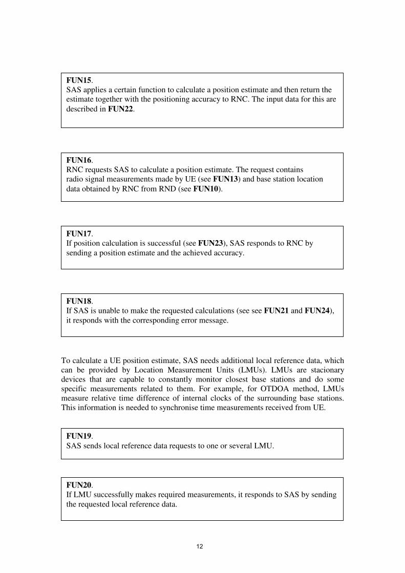
To calculate a UE position estimate, SAS needs additional local reference data, which can be provided by Location Measurement Units (LMUs). LMUs are stacionary devices that are capable to constantly monitor closest base stations and do some specific measurements related to them. For example, for OTDOA method, LMUs measure relative time difference of internal clocks of the surrounding base stations. This information is needed to synchronise time measurements received from UE.
FUN15. SAS applies a certain function to calculate a position estimate and then return the estimate together with the positioning accuracy to RNC. The input data for this are described in FUN22.
FUN19. SAS sends local reference data requests to one or several LMU.
FUN20. If LMU successfully makes required measurements, it responds to SAS by sending the requested local reference data.
FUN16. RNC requests SAS to calculate a position estimate. The request contains radio signal measurements made by UE (see FUN13) and base station location data obtained by RNC from RND (see FUN10).
FUN18. If SAS is unable to make the requested calculations (see see FUN21 and FUN24), it responds with the corresponding error message.
FUN17. If position calculation is successful (see FUN23), SAS responds to RNC by sending a position estimate and the achieved accuracy.
12

SAS contains a database of position calculation functions that calculate a position estimate on the basis of different data or different calculation method. For simplicity, we assume that there is a function that takes three parameters (UE measurements, LMU measurements, and RND data about physical locations of base stations) and returns a pair – the UE position estimate (a pair of numerical values) and achieved positioning accuracy.
The functional requirements describing system communication between different network components are summarised in Table 2.1.
FUN22. SAS invokes a position calculation function with the input parameters: UE measurements, LMU measurements and the physical locations of base stations.
FUN24. If the positioning accuracy achieved by the calculation function does not meet the accuracy requirement (see FUN4), the corresponding error message is returned. In that case, SAS can repeatedly (up to the predefined number of attempts NAlgo) invoke the position calculation function.
FUN21. If LMU is unable to make required measurements, it responds with the corresponding error message. In that case, SAS can repeatedly (up to the predefined number of attempts NLMU) send additional measurement requests to LMU.
FUN23. If position calculation is successful, the invoked position calculation function returns the position estimate together with the positioning accuracy (see FUN5).
13

Table 2.1 Functional requirements for communicating components Requesting component
Responding component
Functional requirements
UE RNC FUN1, FUN2, FUN7, FUN8 RNC RND FUN9, FUN10, FUN11 RNC UE FUN12, FUN13, FUN14 RNC SAS FUN16, FUN17, FUN18 SAS LMU FUN19, FUN20, FUN21 SAS Position Calculation FUN22, FUN23, FUN24 2.4 Services and interfaces In this chapter we will describe the system behaviour in terms of its services and interfaces. From this point of view, the system consists of several layers representing it at different levels of detail. The top layer describes system’s interaction with an external user: what services the system provides, what signals it sends and receives. Each consequent layer describes more system implementation details, so that the bottom layer defines the information transfer between actual network elements. 2.4.1 Layer 1 On the top layer, there is software component Positioning which supports the following interface with the external user (usually called upward interface): it accepts two incoming signals (POSITIONING_REQUEST and POSITIONING_ABORT) and responds with two possible outgoing signals: POSITIONING_CONFIRM and POSITIONING_FAIL_CONFIRM). Each of these signals has certain information attached in the form of signal parameters.
COM1. The user can send POSITIONING_REQUEST signal to Positioning requesting positioning service (see FUN1, FUN4). The signal parameters are UE ID and positioning accuracy.
COM2. The user can send POSITIONING_ABORT signal to Positioning requesting to cancel previously requested positioning service (see FUN7). The only parameter of this signal is UE ID.
COM3. Positioning can respond to the user with POSITIONING_CONFIRM signal, if the positioning request was successfully completed (see FUN2, FUN5). The signal parameters are the position estimate and achieved positioning accuracy.
14

2.4.2 Layer 2 The second layer describes how the positioning service is decomposed into several subservices of smaller grannularity. Each of subservices is provided by an external service component responsible for its execution. The downward interface of the Positioning component has to be extended to define signals to and from the subservice components it relies on. The positioning service consists of four subservices: DB Enquiry, UE Enquiry, LMU Measurement, and Algorithm Invocation. These services should be executed in the order presented. The software component Positioning is also decomposed into ServiceDirector, which is responsible for orchestrating the execution of the whole service, and four “handlers” – subcomponents responsible for communication with the corresponding external service components. There are correspondingly four handlers: DBHandler, UEHandler, LMUHandler, and AlgoHandler. Since ServiceDirector replaces the service component Positioning, it implements the upward interface provided by Positioning.
In addition, ServiceDirector can send an initiating service request signals to the corresponding handlers, attaching necessary data as signal parameters. The handlers forward this request, by sending a signal to the corresponding external service components. Once the external component finishes its request, it returns a signal informing about success (with some data describing the result of service execution) or a failure (with some error message attached) of a subservice to the handler. The handler then relays this signal to the ServiceDirector.
COM4. Positioning can respond to the user with POSITIONING_FAIL_CONFIRM signal, if the positioning request failed or was cancelled by the user (see COM2, FUN2, FUN8). The signal parameter is error message describing the cause of a failure.
COM5. ServiceDirector can accept POSITIONING_REQUEST and POSITIONING_ABORT signals sent by the user, and can respond with POSITIONING_CONFIRM and POSITIONING_FAIL_CONFIRM signals (see COM1, COM2, COM3, COM4).
15

In addition to being simple mediators between ServiceDirector and the corresponding service components, the handlers also contain simple fault tolerance mechanisms. In particular, a handler analyses the error message and other data received from a service component, and decides whether sending an additional service request is needed. In other words, if a handler decides that erroneous situation is recoverable, it can repeatedly try to send service requests. Otherwise (i.e., error is unrecoverable), a handler reports the error to ServiceDirector by sending the corresponding error message.
Fig.2.2 Functional architecture of Layer 2
Let us now to formulate requirements for four handlers of the positioning service. For DB Enquiry, we have the following requirements.
COM6. ServiceDirector can initiate DB Enquiry by sending DB_HANDLER_REQUEST signal to DBHandler. The UE ID is a parameter of the signal.
COM7. After receiving DB_HANDLER_REQUEST signal from ServiceDirector, DBHandler sends DB_REQUEST signal to Radio Network Database(RND). The UE ID is a parameter of the signal (see FUN9).
COM8. If RND enquiry was succesfully completed, RND responds by sending DB_RESPONSE signal to DBHandler. DB data describing a list of base stations surrounding UE are included as signal parameters. See also FUN10.
User
Service Director
DB Handler UE Handler LMU Handler Algo Handler
Radio NetworkDatabase
UserEquipment
LocationMeasurementUnit
PositionAlgorithmServer
16

For UE Enquiry, we have the following requirements.
COM9. If RND enquiry failed, RND responds by sending DB_FAILURE signal to DBHandler. Error message describing the cause of a failure is included as a signal parameter. See also FUN11.
COM10. After receiving DB_FAILURE signal from RND, DBHandler can repeatedly send DB_REQUEST signal to RND, asking to execute the database enquiry again (see FUN11).
COM11. If DBHandler decides that DB Enquiry was succesfully completed, it sends DB_ENQUIRY_RESPONSE signal to ServiceDirector. The list of base stations (obtained from RND) is included as a parameter.
COM12. If DBHandler decides that DB Enquiry has unrecoverably failed, it sends DB_ENQUIRY_FAILURE signal to ServiceDirector. The error message describing the cause of a failure is included as a parameter.
COM14. After receiving UE_HANDLER_REQUEST signal from ServiceDirector, UEHandler sends UE_MEASUREMENT_REQUEST signal to the UE. The UE ID and UE position data received from RND are included as parameters of the signal. See also FUN12.
COM13. ServiceDirector can initiate UE Enquiry by sending UE_HANDLER_REQUEST signal to UEHandler. The UE ID and UE position data received from RND are included as parameters of the signal.
17

For LMU Measurement, we have the following requirements.
COM15. If UE enquiry was succesfully completed, the UE responds by sending UE_MEASUREMENT_RESPONSE signal to UEHandler. Radio measurements data calculated by the UE are included as signal parameters. See also FUN13.
COM17. After receiving UE_MEASUREMENT_FAILURE signal from the UE, UEHandler can repeatedly send UE_MEASUREMENT_REQUEST signal to the UE, asking to execute the UE enquiry again. See also FUN14.
COM18. If UEHandler decides that UE Enquiry was succesfully completed, it sends UE_ENQUIRY_RESPONSE signal to ServiceDirector. The radio measurements calculated by the UE are included as parameters.
COM19. If UEHandler decides that UE Enquiry has unrecoverably failed, it sends UE_ENQUIRY_FAILURE signal to ServiceDirector. The error message describing the cause of a failure is included as a parameter.
COM20. ServiceDirector can initiate LMU Measurement by sending LMU_HANDLER_REQUEST signal to LMUHandler. The UE ID and UE position data received from RND are included as parameters of the signal.
COM16. If UE enquiry has failed, the UE responds by sending UE_MEASUREMENT_FAILURE signal to UEHandler. Error message describing the cause of a failure is included as a signal parameter. See also FUN14.
18
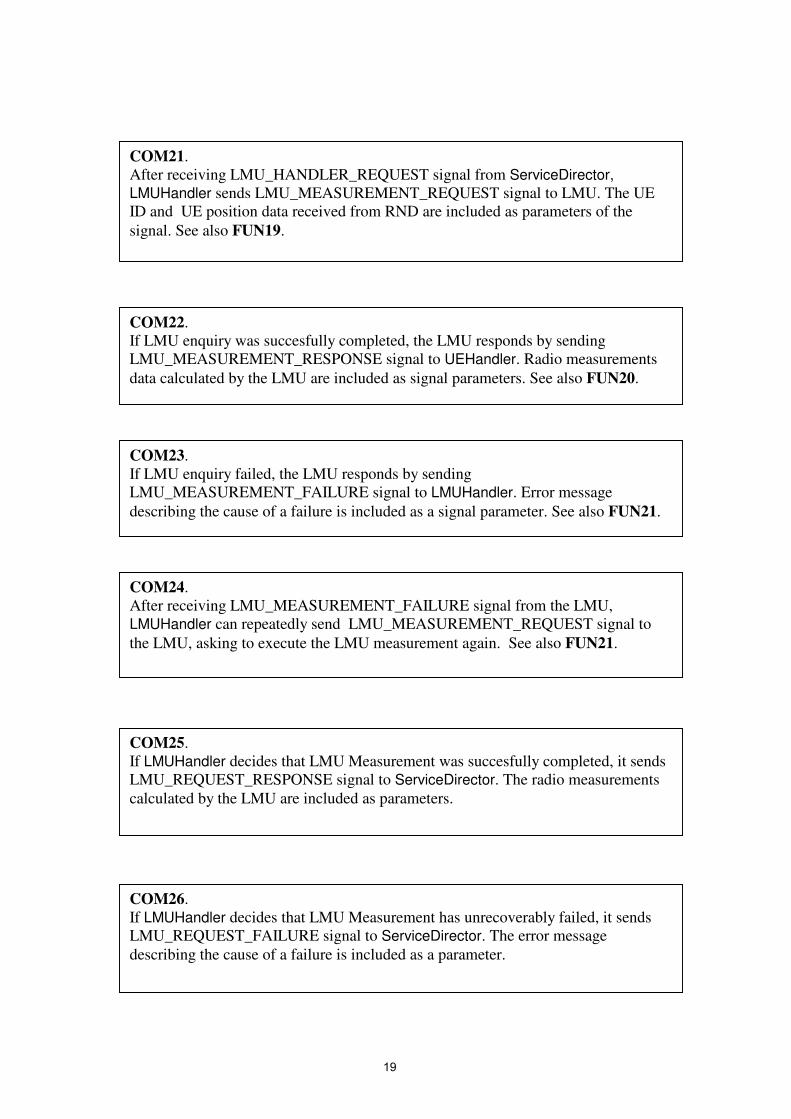
COM21. After receiving LMU_HANDLER_REQUEST signal from ServiceDirector, LMUHandler sends LMU_MEASUREMENT_REQUEST signal to LMU. The UE ID and UE position data received from RND are included as parameters of the signal. See also FUN19.
COM22. If LMU enquiry was succesfully completed, the LMU responds by sending LMU_MEASUREMENT_RESPONSE signal to UEHandler. Radio measurements data calculated by the LMU are included as signal parameters. See also FUN20.
COM23. If LMU enquiry failed, the LMU responds by sending LMU_MEASUREMENT_FAILURE signal to LMUHandler. Error message describing the cause of a failure is included as a signal parameter. See also FUN21.
COM24. After receiving LMU_MEASUREMENT_FAILURE signal from the LMU, LMUHandler can repeatedly send LMU_MEASUREMENT_REQUEST signal to the LMU, asking to execute the LMU measurement again. See also FUN21.
COM25. If LMUHandler decides that LMU Measurement was succesfully completed, it sends LMU_REQUEST_RESPONSE signal to ServiceDirector. The radio measurements calculated by the LMU are included as parameters.
COM26. If LMUHandler decides that LMU Measurement has unrecoverably failed, it sends LMU_REQUEST_FAILURE signal to ServiceDirector. The error message describing the cause of a failure is included as a parameter.
19

For Algorithm Invocation, we have the following requirements.
COM27. ServiceDirector can initiate Algorithm Invocation by sending ALGO_HANDLER_REQUEST signal to AlgoHandler. TheUE position data received from RND, UE measurement data, and LMU measurement data are included as parameters of the signal.
COM28. After receiving ALGO_HANDLER_REQUEST signal from ServiceDirector, AlgoHandler sends ALGO_INVOCATION_REQUEST signal to the Positioning Algorithm Database. TheUE position data received from RND, UE measurement data, and LMU measurement data are included as parameters of the signal. See also FUN22.
COM29. If Algorithm invocation was succesfully completed, the Positioning Algorithm Database responds by sending ALGO_INVOCATION_RESPONSE signal to AlgoHandler. The calculated UE position estimate and the achieved accuracy are included as signal parameters. See also FUN23.
COM30. If Algorith Invocation failed, the Positioning Algorithm Database responds by sending ALGO_INVOCATION_FAILURE signal to AlgoHandler. Error message describing the cause of a failure is included as a signal parameter. See also FUN24.
COM31. After receiving ALGO_INVOCATION_FAILURE signal from the Positioning Algorithm Database, AlgoHandler can repeatedly send ALGO_INVOCATION_REQUEST signal to the the Positioning Algorithm Database, asking to execute the position calculation again. See also FUN24.
20

If any of subservices fail (i.e., ServiceDirector gets the corresponding error signal from one of the handlers), the whole positioning service is considered as failed. ServiceDirector then sends the corresponding error message to the user.
2.4.3 Layer 3 The third layer describes how service components are distributed over the network. ServiceDirector and four handlers are distributed between RNC and SAS network elements. ServiceDirector is further decomposed into two parts – RNC_ServiceDirector and SAS_ServiceDirector.
RNC_ServiceDirector implements the top-level interface with the user. In addition, it supports interfaces for communication with RNC (during DB Enquiry) and UE (during UE Enquiry). In other words, it also implements ServiceDirector – DBHandler and ServiceDirector – UEHandler interfaces.
COM32. If AlgoHandler decides that Algorithm Invocation was succesfully completed, it sends ALGO_REQUEST_RESPONSE signal to ServiceDirector. The calculated UE position estimate and the achieved accuracy are included as signal parameters.
COM33. If AlgoHandler decides that Algorithm Invocation has unrecoverably failed, it sends ALGO_REQUEST_FAILURE signal to ServiceDirector. The error message describing the cause of a failure is included as a parameter.
COM34. If ServiceDirector gets a signal about a failure of any of subservices (i.e., DB_ENQUIRY_FAILURE, UE_ENQUIRY_FAILURE, LMU_MEASUREMENT_FAILURE, ALGO_REQUEST_FAILURE), it sends POSITIONING_FAIL_CONFIRM signal to the user (see COM4).
COM35. RNC_ServiceDirector can accept POSITIONING_REQUEST and POSITIONING_ABORT signals sent by the user, and can respond with POSITIONING_CONFIRM and POSITIONING_FAIL_CONFIRM signals (see COM1, COM2, COM3, COM4).
21

SAS_ServiceDirector supports interfaces for communication with LMU (during LMU Measurement) and Positioning Algorithm Server (during Algorithm Invocation). In other words, it also implements ServiceDirector – LMUHandler and ServiceDirector – AlgoHandler interfaces.
Fig.2.3 Functional architecture of Layer 3 Since ServiceDirector is now split between two distant network elements, we should describe communication between RNC_ServiceDirector and SAS_ServiceDirector, while executing the UE positioning service. The communication is governed by the PCAP communication protocol ([2.1,2.2]). Position Calculation Application Part (PCAP) is a communication protocol and part of the UE positioning system in a UMTS network. PCAP defines the interface and corresponding signalling procedures
COM36. RNC_ServiceDirector can send signals to and accept signals from DBHandler and UEHandler according to the interfaces described in COM6-COM12 and COM13-COM19.
COM37. SAS_ServiceDirector can send signals to and accept signals from LMUHandler and AlgoHandler according to the interfaces described in COM20-COM26 and COM27-COM33.
DB
UE
��LMU
Algo
RNC Service Director
SAS Service Director
User
22

to enable the interaction between RNC and SAS network elements in the process of performing a position estimate of the UE. After completing successfully two first subservices (DB Enquiry and UE Enquiry), RNC_ServiceDirector sends request signal to SAS_ServiceDirector together with data required for finishing position calculation. In response, SAS_ServiceDirector sends signal with the position estimate and achieved accuracy (in case of success) or error message (in case of a failure). Communication is realised using signalling protocols allowing data transfer between distant network elements. Both RNC_ServiceDirector and SAS_ServiceDirector have subcomponents called Peer Proxies, which are responsible for providing PDU (Protocol Data Unit) communication over the network (according to the PCAP protocol). Peer Proxy encodes outgoing PDU message before sending it to the underlying transport layer. Similarly, Peer Proxy decodes incoming transport service messages containing encoded PDU values. We assume that there are corresponding functions (signals) of the transport layer that realise the actual data transfer.
COM38. RNC_ServiceDirector can send SAS_REQUEST signal to RNC_PeerProxy. UE ID, UE position data from RND, and UE measurement data are included as parameters. See also FUN16.
COM39. RNC_PeerProxy encodes received data and forwards them to the underlying transport layer, which makes the actual data transfer between RNC and SAS.
COM40. SAS_PeerProxy decodes received data from the underlying transport layer, and sends SAS_REQUEST signal to SAS_ServiceDirector, attaching the decoded data as parameters.
COM41. If UE positioning request is successfully completed, SAS_ServiceDirector sends SAS_RESPONSE signal to SAS_PeerProxy. The UE position estimate and the achieved accuracy are included as parameters. See also FUN17.
23

Fig.2.4 Communication between RNC and SAS
COM44. RNC_PeerProxy decodes data received from the underlying transport layer, and, if they indicate successful UE position calculation, sends SAS_REQUEST signal to SAS_ServiceDirector, attaching the decoded data as parameters.
COM45. RNC_PeerProxy decodes received data from the underlying transport layer, and, if they indicate a failure of UE position calculation, sends SAS_FAILURE_REQUEST signal to SAS_ServiceDirector, attaching the decoded data as parameters.
COM43. SAS_PeerProxy encodes data received from SAS_ServiceDirector and forwards them to the underlying transport layer, which makes the actual data transfer between SAS and RNC.
COM42. If UE positioning request has failed, SAS_ServiceDirector sends SAS_FAILURE_RESPONSE signal to SAS_PeerProxy. The error message indicating the cause of a failure is included as a parameter. See also FUN18.
RNC SAS
Peer Proxy Peer Proxy
Transport Layer
24

2.4.4 References 2.1. 3GPP. Technical specification 25.305: Stage 2 functional specification of UE
positioning in UTRAN. See http://www.3gpp.org/ftp/Specs/html-info/25305.htm
2.2. 3GPP. Technical specification 25.453: UTRAN Iupc interface positioning calculation application part (pcap) signalling. See http://www.3gpp.org/ftp/Specs/html-info/25453.htm
25

SECTION 3. REQUIREMENT DOCUMENT FOR CASE STUDY 2: ENGINE FAILURE MANAGEMENT SYSTEM1
3.1. Introduction An embedded Engine control system comprises of several subsystems. The control subsystem, executes algorithms on its inputs in order to provide the desired fuel demand to the engine. The engine failure management subsystem provides a protective wrapper to the control subsystem, protecting it from failures in its system inputs and so enhancing the dependability of the control system. It detects failures, and then manages these failures in order to provide the control subsystem with an acceptable input or graceful degradation of behaviour. This requirement specification describes the functional requirement of the failure management subsystem.
Features of the Engine Failure Management subsystem Detection of system sensor input failures Confirmation of system sensor input failures Temporary actions during confirmation Failure actions after confirmation Failure classification Failure labelling and notification Degraded action depending upon severity
The specification first describes the generic features of the requirement then later provides an example of a particular instance of such a system in tabular form. The instance is traceable to the generic description by references. This document is organised into two separate texts (1) The reference text which contains the requirement and assumptions (2) The explanation text, which may give further explanation to the requirement/assumptions and there purpose. The reference text is separated from the explanation text (boxed and given an identifier).
1 This document is the property of AT Engine Controls Ltd. and no part may be reproduced, transmitted in any form or by any means, electronic, mechanical, photo copying, recording or otherwise, transferred to other documents, disclosed to a third party or used for any purpose other than that which this document was produced, without the express written permission of AT Engine Controls Ltd.
26

3.2. Overview of Sub-System Functionality The subsystem monitors sensor inputs to be used in other (client) subsystems. The subsystem checks the condition of a set of inputs from some external equipment to detect abnormal conditions including transducer failures and failures of the equipment. To avoid reacting to transient noise on the inputs abnormal conditions must be confirmed over a number of readings before any permanent action is taken. During this confirmation period the subsystem must provide acceptable actions in place of using suspect readings. If the abnormal condition is confirmed, more permanent action may be taken to provide longer term acceptable operation of the client subsystems. The following requirements have been given identifiers according to a taxonomy that is described in the next section.
PROC1 The subsystem executes on a given process cycle.
DET1 The subsystem detects abnormal conditions of inputs caused by failures of the external equipment.
OUT1 Inputs that are found to be in a normal condition may be passed on as outputs (if they are required by other subsystems).
CONF1 When an abnormal condition is detected, the subsystem confirms the suspected failure over a period of time. During this time the condition may recover.
ACT1 The subsystem takes some temporary action to simulate acceptable input while a suspected fault is being confirmed.
ACT2 The subsystem simulates acceptable input conditions or performs other permanent failure actions if it confirms an abnormal condition of the inputs.
PROC2 All tests will be implemented by configuring the generic requirements specified in this document to meet the specific requirements of the application (as shown in Tables 3.9.1 to 11).
27

3.3. Taxonomy This specification identifies and categorises environmental assumptions (ENV), processing decisions (PROC), functional requirements (FUNC) and performance requirements (PERF) about the failure management subsystem.
Figure 3.3.1 - Top level classification of specification items illustrated in UML An input (INP) may have many associated tests and a test may utilise many inputs. A test is made up of a detection method (DET) and confirmation mechanism (CONF) pair. Each test also has a collection of conditions (COND) that must be satisfied for the test to be valid. A confirmation mechanism contains three different actions (ACT), a healthy action, a temporary action (taken while a test is confirming) and a permanent action (taken when a test has confirmed). Each action is associated with at least one output (OUT) that it modifies.
Figure 3.3.2 – Overview of functionality expressed as a UML class diagram
The detection mechanism of a test can be further classified as a comparison of magnitude (MAG), a comparison of rate of change (RATE), a comparison with a predicted value (PRED) or a comparison between several inputs (MULT). Hence, functional requirements are identified in the following hierarchy.
28

Figure 3.3.3 – Expansion of functional classification In accordance with this classification, the reference text in this document is organised around, and identified by, the following taxonomy. Assumptions
ENV - is used to label assumptions about the environment of the failure management subsystem
Decisions PROC - is used to label decisions about how the system will be processed
Functional requirements FUNC - is used to label requirements dealing with general functionality not
covered by another category. INP - is used to label requirements about use of inputs COND - is used to label requirements dealing with conditions under which a test
is performed. DET - is used to label requirements dealing with detection.
DET_MAG - is used when dealing with magnitude test detection. DET_MULT - is used when dealing with multiple input test detection. DET_PRED - is used when dealing with predicted value test detection. DET_RATE - is used when dealing with rate test detection.
CONF - is used to label requirements dealing with the confirmation of failures. ACT - is used to label requirements dealing with actions taken either normally
or in response to failures. OUT - is used to label requirements about providing outputs
Non-functional requirements PERF - is used to label requirements dealing with performance.
29

3.4. Environment The environment consists of various hardware and software components which provide sensor readings and variables for the failure management subsystem. The failure management subsystem resides within an engine control unit. Other subsystems within the same unit interact with the failure management subsystem.
Figure 3.4 – Environment of Failure Management Subsystem The following components can be identified in the environment of the failure management subsystem within the engine control unit.
ENV1 The subsystem environment consists of Control Subsystem, Engine Control Unit platform including I/O facilities and scheduler.
ENV2 The control subsystem uses the outputs from the failure management subsystem to determine how it should control the fuel flow to the engine.
The following equipment can be identified in the environment of the engine control unit (in which the failure management subsystem operates).
ENV3 The engine control unit environment is the Engine, Ambient Sensors, Aircraft Sensors, Engine Sensors and Cockpit Sensors (including Power Lever PL) and another complete engine system.
30

Engine
ENV4 The engine can be in the following modes
Start, Start Abort, Lightoff, Running, Shutdown
Engine controller
ENV5 The engine controller performs control of the engine fuel demand based on the controllers inputs
Sensors A sensor outputs a measurement of the device it is reading. Depending upon the type of sensor it will give either a binary or analogue output. A sensor does not output an error status. In more complicated devices several sensors may be required to be used in combination to provide the reading of a device. In order to maintain system dependability, a device may have several sensors which are used to measure the same input.
ENV6 One type of sensor produces a binary output.
ENV7 One type of sensor produces an analogue output.
ENV8 A sensor is assumed to read over the full range of the device
ENV9 Some external devices may have multiple sensors whose output can later be combined to provide a device reading.
ENV10 Some external devices may have multiple sensors which provide alternative measurements of the same source
The PL device is essentially a lever device which is used in the cockpit to demand more fuel to the engine. It is an instance of ENV9 that has two sensors (offset and direction) whose output can be combined to provide the full demand reading. It also contains an instance of ENV10 as it has an interlock output which is an abstract representation of lever position. (ie in a locked position or in between).
ENV11 The Power Lever (PL) consists of the offset(PL), directional gain (PLg) and interlock(PLi) Ref ENV9 and ENV10
31

Where Lever position – basic analogue range of lever, it can be locked into three positions stopped, idle and full. Lever offset –magnitude of offset on the idle position Direction - determines the direction of the offset from the idle position Interlock – set when the lever is in Stop Idle or Full. It is used for fault detection
ENV12 The PL components operate in the following modes
Lever Position
Lever in degrees
PL offset
Lever directional gain PLg
Interlock PLi
Stop 0 30 Off On Stop-Idle 0-30 30- 0 Off Off Idle 30 0 On or Off On Idle- full 30-60 0-30 On Off Full 60 30 On On
The computed output used for control corresponds to the lever demand in degrees. This is derived as follows.
ENV13 When the Directional gain (PLg) is off
PL in degrees = 30° – PL offset
When the Directional gain (PLg) is on
PL in degrees = 30° + PL offset
32

3.5. Subsystem Interface The subsystem handles several types of input and output variables described below. The specific variables used are referenced in Tables 3.9.1 & 2 later.
Input The subsystem uses input variables, which represent sensor readings or settings from other client subsystems. All variables will be represented by digitalised analogue or boolean states. Where sensors are duplicated then different variables are assigned, the inputs are said to be homogenous. The functionality is as follows:
INP1 The subsystem uses input variables which contain either digitalised values or Boolean states.
INP2 The subsystem input variables represent either sensor values or other subsystem variables.
INP3 The subsystem sensor variables represent the scaled full range of the sensor .
INP4 Some “other subsystem” input variables represent engine states.
INP5 Some “other subsystem” input variables represent the controller state.
INP6 Some “other subsystem” input variables represent the control subsystem output.
Output The subsystem output variables (values and boolean states) to be used by other client subsystems.
OUT2 The subsystem produces output variables which contain either values or Boolean states.
Variables representing sensor values after failure management These variables are output to the control subsystem and represent failure managed sensor input values. They may contain the actual input value of a sensor input variable or as in the case of a failed input, some substitute value. In some cases the output variable may be computed from a combination of the actual input values. Where there
33

are multiple homogenous sensors for the same input only one value will be used. The selection of which sensor value is used is given in the tables.
OUT3 Some subsystem output variables represent sensor values to be used by the control subsystem
OUT4 Some subsystem output variables are computed from a combination of sensor inputs.
OUT5 Some subsystem output variables are derived from a selection of sensor inputs.
Variables that control logic in other subsystems These variables initiate further actions in the client subsystems, when a sensor input is failing or failed. Typically this may include fault storage and logic to select actions such as system freezing.
OUT6 Some subsystem output variables control logic in other subsystems.
34
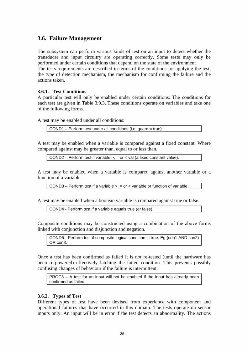
3.6. Failure Management The subsystem can perform various kinds of test on an input to detect whether the transducer and input circuitry are operating correctly. Some tests may only be performed under certain conditions that depend on the state of the environment The tests requirements are described in terms of the conditions for applying the test, the type of detection mechanism, the mechanism for confirming the failure and the actions taken. 3.6.1. Test Conditions A particular test will only be enabled under certain conditions. The conditions for each test are given in Table 3.9.3. These conditions operate on variables and take one of the following forms. A test may be enabled under all conditions:
COND1 – Perform test under all conditions (i.e. guard = true).
A test may be enabled when a variable is compared against a fixed constant. Where compared against may be greater than, equal to or less than.
COND2 – Perform test if variable >, = or < val (a fixed constant value).
A test may be enabled when a variable is compared against another variable or a function of a variable.
COND3 – Perform test if a variable >, = or < variable or function of variable.
A test may be enabled when a boolean variable is compared against true or false.
COND4 - Perform test if a variable equals true (or false).
Composite conditions may be constructed using a combination of the above forms linked with conjunction and disjunction and negation.
COND5 - Perform test if composite logical condition is true. Eg (con1 AND con2) OR con3.
Once a test has been confirmed as failed it is not re-tested (until the hardware has been re-powered) effectively latching the failed condition. This prevents possibly confusing changes of behaviour if the failure is intermittent.
PROC3 – A test for an input will not be enabled if the input has already been confirmed as failed.
3.6.2. Types of Test Different types of test have been devised from experience with component and operational failures that have occurred in this domain. The tests operate on sensor inputs only. An input will be in error if the test detects an abnormality. The actions
35

that are undertaken on the result of a test will depend on the confirmed status of the input and the state of the system this is discussed later (see section 7). Each test may have configurable parameters to allow the characteristics peculiar to a particular sensor input to be configured e.g. its magnitude range. The test instances are referenced in Tables 3.9.4 to 8.
DET2 The subsystem performs detection of errors (failures) on its INP1 inputs using a selection of magnitude, rate and multiple tests. Ref. DET-MAG, DET_RATE, DET_PRED, DET_MULT.
DET3 An input will be in error if a test detects a discrepancy.
DET4 The status of an input will be determined by the confirmation mechanism after test.
Since devices may have single or multi sensor outputs then tests have been developed to cover both these configurations and are described below. 3.6.3. Single Sensor Input Tests The Magnitude test (Mag) This type of test is intended to detect abnormal values through the detection of out of device range sensor readings or readings infeasible with the operational state. The input from the sensor is compared to a reference limit(s) which may be specific to the input. (The limit will usually have an upper and lower limit which denotes the range). If the limit is exceeded, then the input is in error otherwise it is in range. The limit may vary as a function of engine state, in some cases a variable limit may be computed from a function of another signal. The specific configuration of each input limit is given in Table 3.9.5.
DET_MAG1 Compares input value against a magnitude (range) limit. The input is in error if the limit is exceeded.
DET_MAG2 The range limit for an input may be variable or fixed.
The Rate test (Rate) This test is intended to detect incorrect readings when an input value is changing over time. It detects if an input changes too much over a fixed time by comparing the change in value over a fixed time period with a fixed limit. The input is in error if the limit is exceeded.
36

DET_RATE1 Compares a change in input value over a fixed time interval against a fixed limit. ie ((In-In-1)/delta T)>lmt. Where In-1 is the previous reading of Input ln. The input is in error if the limit is exceeded.
Predicted value test (Pred v) This test is intended to detect incorrect readings based on the intended operational state of the system. The system predicts a value or range that a particular input may reach over a fixed time period. It can detect where movement is expected but not achieved. In application it can be regarded as a form of magnitude test where limits are constantly varying. However the difference is that the variable limit values are computed from what the control system has expected the engine system to have reached as a result of a control action rather than what the current operational state is. The predicted values may be derived from the control subsystem.
DET_PRED1 Compare input value against a computed value. The input is in error if the discrepancy lies outside a tolerance of this value.
3.6.4. Multiple Homogenous Input Tests These tests refer to testing devices that have duplicated sensors. Each of the duplicated sensor input is tested first using the single sensor tests. Only inputs that are not in error are then compared. Only one input is chosen for control.
Dual sensor Difference test (Diff) A comparison between two sensors of the same source are compared and if their difference lies outside a given tolerance then a sensor is in error.
DET_MULT1 Compares an input value against a different input value from the same INP2 source. A chosen input is in error if the difference exceeds a fixed limit.
PROC4 The comparison of input values from the same source are only enabled if the inputs have passed their DET-MAG,DET-RATE or DET_PRED tests.
PROC5 This requirement has been deleted.
3.6.5. Multiple Heterogeneous Input Tests These tests refer to testing specific devices that have multi sensor outputs that can only have certain combination of values. Incorrect combinations will be considered as the device in error.
DET_MULT2 Device specific tests are identified for PL.
37

DET_MULT3 Device specific tests involve comparing multi input values from the device.
DET_MULT4 An error will be detected if an Invalid Input combination occurs.
DET_MULT5 Some multi input values are compared against limits in order to set or clear latch states
3.6.6. Test Scheduling The subsystem applies the tests in two stages and these can be expressed as conditions.
COND6 Groups of tests can be applied in different stages.
COND7 Test Stages may depend on conditions Ref Cond_1, Cond_2,Cond _3, Cond_4.
The frequency of each test execution can be configured. Each test will be undertaken, providing the test conditions associated with it are satisfied. In a multiple input test the timeliness of acquiring the input values to be compared should be considered in order to avoid false detections due to comparison between values representing different points in time.
PROC6 A multi input test should be applied at an interval where the frequency of individual input readings cannot affect the test.
3.6.7. Test Input Status Confirmation The subsystem needs to be tolerant to isolated errors, which may be transient, so as to maintain stability in the control system. In order to achieve this, a failure confirmation mechanism is employed to confirm when a firm fault has been established. If an input is in error but not confirmed as a fault, then some action may still occur, but the input will still be used if the confirmation recovers (see section below). However once failed, the failure will normally be latched which means it cannot be reset until initial power up and the input is not recoverable. See section on actions below.
CONF2 A sensor input will have been determined to have failed, only if a failure confirmation mechanism has confirmed it.
CONF3 A confirmed failure may be latched. A latched failure cannot be reset until system reset.
38
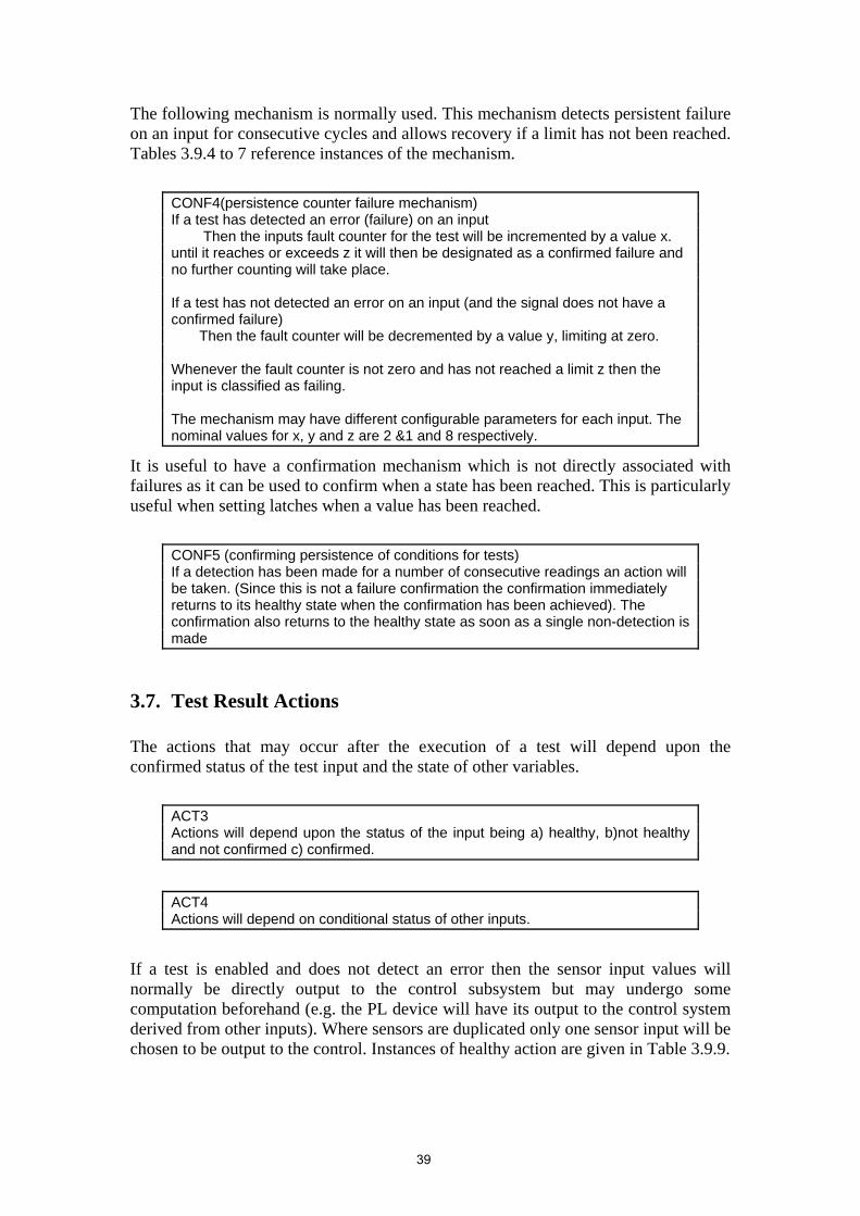
The following mechanism is normally used. This mechanism detects persistent failure on an input for consecutive cycles and allows recovery if a limit has not been reached. Tables 3.9.4 to 7 reference instances of the mechanism.
CONF4(persistence counter failure mechanism) If a test has detected an error (failure) on an input Then the inputs fault counter for the test will be incremented by a value x. until it reaches or exceeds z it will then be designated as a confirmed failure and no further counting will take place. If a test has not detected an error on an input (and the signal does not have a confirmed failure) Then the fault counter will be decremented by a value y, limiting at zero. Whenever the fault counter is not zero and has not reached a limit z then the input is classified as failing. The mechanism may have different configurable parameters for each input. The nominal values for x, y and z are 2 &1 and 8 respectively.
It is useful to have a confirmation mechanism which is not directly associated with failures as it can be used to confirm when a state has been reached. This is particularly useful when setting latches when a value has been reached.
CONF5 (confirming persistence of conditions for tests) If a detection has been made for a number of consecutive readings an action will be taken. (Since this is not a failure confirmation the confirmation immediately returns to its healthy state when the confirmation has been achieved). The confirmation also returns to the healthy state as soon as a single non-detection is made
3.7. Test Result Actions The actions that may occur after the execution of a test will depend upon the confirmed status of the test input and the state of other variables.
ACT3 Actions will depend upon the status of the input being a) healthy, b)not healthy and not confirmed c) confirmed.
ACT4 Actions will depend on conditional status of other inputs.
If a test is enabled and does not detect an error then the sensor input values will normally be directly output to the control subsystem but may undergo some computation beforehand (e.g. the PL device will have its output to the control system derived from other inputs). Where sensors are duplicated only one sensor input will be chosen to be output to the control. Instances of healthy action are given in Table 3.9.9.
39

ACT5 Some sensor input variables that are not in error will be output to the control subsystem.
ACT6 Some sensor input variables that are not in error will be combined for output to the control subsystem.
Multiple sensor input selection Where more than two sensors are duplicated then the system selects the sensor from the inputs by finding the median of the sensors. The median is found by selecting the middle value of a sorted set of sensor values in ascending order. Where the values are even then the middle plus one sensor is chosen.
ACT7 Some healthy multiple sensor input variables need to be selected according to some mechanism before being sent to the control subsystem. Where multiple inputs are available from the same external source ie multiple homogenous inputs. Then the median of the sensor input is chosen from the healthy sensors.
If a test is enabled but detects an error then a temporary action will occur as long as the input has not been confirmed failed.
ACT8 Temporary actions are defined as actions initiated by the subsystem when an input status is being confirmed.
ACT9 This requirement has been deleted.
ACT10 Where a test has found a sensor input variable in error and the sensor input has not already been confirmed failed by the confirmation mechanism, then the input will not be suitable for selection for output to control.
When an input value is in error and its the fault confirmation counter is non zero and has not reached its limit, then the control subsystem will typically be given the last value of the input that has not failed i.e. the last good value. There may be an additional system action such as a system freeze. System freeze refers to setting an output in the failure management subsystem (ref OUT6.1 Table 3.9.2) which will freeze the fuel flow in the control system. The specific temporary action for each input is given in Table 3.9.10.
ACT11 A Temporary action will substitute a value for the erroneous input.
ACT12 A temporary action may set other outputs.
40

3.7.1. Confirmed Failure Actions Confirmed failure actions refer to those actions that apply after an input has been confirmed failed by the confirmation mechanism. All confirmed input failures would be identified and logged in the output fault flags (ref Table 3.9.2). All fault flags are latched. A confirmed action may perform a latched control action i.e. it cannot return to using the original input unless the system is reset on power up. Confirmed failure actions like the temporary actions may substitute values or variables for the failed input and may also set other outputs. The confirmed failure action will depend upon the state of the subsystem and the severity of fault. The specific confirmed action for each input is given in the confirmed action table. Where the confirmed action is severe it is termed a hard fault action then the subsystem generally initiate to freeze the fuel flow rate to the engine by setting the system freeze output. The hard fault action is always latched. Where the confirmed action is less severe it is termed a soft fault action when this occurs then the subsystem will normally substitute a value to be used by the control subsystem for it’s input and may perform some additional control actions through setting of its output variables to the subsystem. The soft fault action will normally be latched.
ACT13 Confirmation Action refers to actions initiated by the subsystem when a sensor input has been confirmed failed by the confirmation mechanism.
ACT14 Upon confirmation of a fault then the transitory failure actions will be superseded by confirmation actions.
ACT15 A confirmation action will substitute a value for the input and may set other control variables.
ACT16 Most confirmed actions are latched.
ACT17 A latched action cannot be reset until the system has been given a reset.
ACT18 A confirmation action that results in a system freeze will always be a latched action.
ACT19 All confirmed faults are classified into two categories of criticality. Hard Faults = Failures that could cause unacceptable operation. Soft Faults = Failures that provide either no impact on normal operation or limited degradation.
41

ACT20 All confirmed failures (faults) will be logged in fault flags.
ACT21 All fault flags are latched.
42

3.8. Performance Constraints PERF1 The rate test interval must not be shorter than the execution cycle.
PERF2 The engine failure management system must be able to perform its worst case tests for all its input within the execution cycle time and within the other demands on the processor time for the cycle.
PERF3 Each input is required to be tested within a frequency consistent with its output usage.
43

3.9. Specific Requirements for Fm1 Application The following tables provide the specific requirements for a failure management application Fm1 from which the above generic requirements have been derived and are referenced. The table data is effectively a parameterisation of the generic requirements.
3.9.1. Inputs This table defines the inputs and their attributes for a particular application instance. For generic description see Subsystem Interface section. Table 3.9.1. Ref Name Type
[INP1] Range [INP3]
Res Description Freq mS
INP5.1 CYCLE_NO digital 1..16 1 Execution cycle counter (wraps after 16)
24
INP5.2 POWERUP Boolean on/off - control system in power up phase
24
INP4.1 START_MODE Boolean on/off - control system performing start
24
INP4.2 LIGHTOFF Boolean on/off - control system detected engine lit
24
INP4.3 START_ABORT Boolean on/off - control system aborted start 24 INP4.4 RUN_MODE Boolean on/off - control system completed start 24 INP6.5 FFp digitised 0 to
3000pph 0.1 pph
Fuel Flow Predicted 24
INP2.1 ET1 digitised -200 to 2000°F
0.1°F Engine Temperature sensor 1 24
INP2.2 ET2 digitised -200 to 2000°F
0.1°F Engine Temperature sensor 2 24
INP2.3 ET3 digitised -200 to 2000°F
0.1°F Engine Temperature sensor 3 24
INP2.4 ET4 digitised -200 to 2000°F
0.1°F Engine Temperature sensor 4 24
INP2.5 ET5 digitised -200 to 2000°F
0.1°F Engine Temperature sensor 5 24
INP2.10 ESa digitised 0-200% 0.01 Engine Speed (main) 24 INP2.11 ESb digitised 0-200% 0.01 Engine Speed (backup) 24 INP2.12 EP digitised 0-
100psia 0.1 Engine Pressure 24
INP2.13 AP digitised 0-25psia 0.1 Ambient Pressure 24 INP2.14 APo digitised 0-25psia 0.1 other engine’s AP 24 INP2.15 EQ digitised -20-
200% 0.1 Engine Torque 24
INP2.16 EQo digitised -20-200%
0.1 other Engine’s Torque 24
INP2.17 ESo digitised 0-200% 0.1 other Engine’s Speed 24 INP2.18 FFm digitised 0 to
3000pph 0.1 Fuel Flow 24
INP2.20 PLm digitised 0 to 30° 0.1 Power Lever (magnitude) 64 INP2.23 OV digitised 0 to 50v 1v Voltage OR 24 INP2.24 BV digitised 0 to 50v 1v Battery Voltage 24 INP2.27 PLi boolean on/off - PL interlock test 24 INP2.28 PLg boolean on/off - PL gain 24 INP2.29 ETo digitised -200 to
2000°F 0.1°F other Engine’s Temperature 24
44

3.9.2. Outputs This table defines the outputs and their attributes for a particular application instance. For generic description see Subsystem Interface section. Note the digitalised output range is a derived property as a result of limiting the input range (ref Table 3.9.1) through magnitude tests (ref Table 3.9.5) and actions (ref Tables 3.9.9, 10, 11). Table 3.9.2. Ref Name Type
[OUT2] Range
Res Description Freq mS
OUT6.1 FREEZE Boolean on/off - disable all control 24 OUT6.34 LOADSHARE Boolean on/off - disable load sharing 24 OUT6.33 DUMP Boolean on/off - open fuel dump valve 24 OUT5.1 cET digitised -100 to
1900 0.1 Engine Temperature 24
OUT5.2 cES digitised 0 to 130 0.01 Engine Speed (main) 24 OUT3.1 cEP digitised 1.5 to 200 0.1 Engine Pressure 24 OUT3.2 cAP digitised 4 to 20 0.1 Ambient Pressure 24 OUT3.3 cEQ digitised -10 to
140 0.1 Engine Torque 24
OUT3.4 cEQo digitised -10 to 140
0.1 other Engine’s Torque 24
OUT3.5 cESo digitised 0 to 130 0.1 other Engine’s Speed 24 OUT3.6 cFF digitised -100 to
200 0.1 Fuel Flow 24
OUT3.7 cPL digitised 0 to 60 0.1 Power Lever 64 OUT3.8 cETo digitised -100 to
1900 0.1 other Engine’s Temperature 24
OUT6.2 fET1 boolean on/off - Engine Temperature fault flag Latched OUT6.3 fET2 boolean on/off - Engine Temperature fault flag Latched OUT6.4 fET3 boolean on/off - Engine Temperature fault flag Latched OUT6.5 fET4 boolean on/off - Engine Temperature fault flag Latched OUT6.6 fET5 boolean on/off - Engine Temperature fault flag Latched OUT6.11 fESa boolean on/off - Engine Speed (main) fault flag Latched OUT6.12 fESb boolean on/off - Engine Speed (backup) fault
flag Latched
OUT6.13 fEP boolean on/off - Engine Pressure fault flag Latched OUT6.14 fAP boolean on/off - Ambient Pressure fault flag Latched OUT6.15 fAPo boolean on/off - other engine’s AP fault flag Latched OUT6.16 fEQ boolean on/off - Engine Torque fault flag Latched OUT6.17 fEQo boolean on/off - other Engine’s Torque fault
flag Latched
OUT6.18 fESo boolean on/off - other Engine’s Speed fault flag
Latched
OUT6.19 fFFm boolean on/off - Fuel Flow Measured fault flag Latched OUT6.20 fFFp boolean on/off - Fuel FlowPredicted fault flag Latched OUT6.21 fPL boolean on/off - Power Lever fault flag Latched OUT6.24 fOV boolean on/off - Voltage OR fault flag Latched OUT6.25 fBV boolean on/off - Battery Voltage fault flag Latched OUT6.27 fOS boolean on/off - Overspeed fault flag Latched OUT6.28 PL_LATCH boolean on/off - latch for PL tests 64 OUT6.29 fEsd boolean on/off - Engine Speed difference test Latched OUT6.30 fFFd boolean on/off - Fuel Flow difference fault flag Latched OUT6.31 fOR boolean on/off - OR test fault flag Latched OUT6.32 fAL boolean on/off - AL fault test flag Latched
45

3.9.3. Conditions This table defines the conditions for a particular application instance. For generic description see the Test Conditions section. The listed conditions define predicates. The refs are used by other tables when referring to test conditions and conditions on actions. Table 3.9.3. Ref Name Predicate Description COND0 never F Always disabled COND1 always T Always enabled COND5.2 starting INP4.1 & INP4.2 & ¬ INP4.3 START_MODE and
LIGHTOFF and not START_ABORT
COND5.3 running INP4.4 & ¬ INP4.1 RUN_MODE and not START_MODE
COND5.4 stopped OUT3.7<10 or OUT5.2<50 cPL<10° or cES<50% COND5.5 not stopped OUT3.7>=10 or OUT5.2>=50 cPL>=10° or cES>=50% COND2.6 other idling OUT3.5>50 cESo>50% COND2.7 Speed for EQ OUT5.2>80 cES>80% COND2.8 Other speed for EQo OUT3.5>80 cESo>80% COND5.9 Other ET and EQ OUT3.8>800 & OUT3.4>40 cETo>800°F and
cEQo>40% COND5.10 speed sensed INP2.10>30 & INP2.11>30 ESa>30% or ESb >30% COND4.11 PL upper quadrant INP2.28=T PLg=T COND4.12 PL lower quadrant INP2.28=F PLg=F COND5.13 PL latch reset INP2.27=F or INP5.2=T PLi=F or POWERUP COND4.14 PL latch OUT6.28=T PL_LATCH=T COND5.15 power up, stopped INP5.2=T & COND5.4 POWERUP=T & COND5.4 COND5.16 PL zero test cond. INP2.27=F or COND4.14 PLi=F or PL_LATCH=T COND5.17 PL interlock test cond. INP2.27=F & COND4.12 PLi=F & PLg=F COND2.18 no volts speed INP2.10<5 ESa <5% COND2.19 alternator speed INP2.10>90 ESa >90% COND5.20 engine overspeed INP2.10>125 & INP2.11>125 ESa> 125% & ESb > 125% COND5.21 engine overspeed INP2.10=<125 or INP2.11=<125 ESa =< 125% or ESb =<
125% COND5.22 no confirmed freeze
faults ¬((OUT6.11=T & OUT6.12=T) or (OUT6.14=T & OUT6.15=T) or ((INP5.2=T or OUT6.20=T) & OUT6.19=T) & OUT6.30=T)
not((fESa=T & fESb=T) or (fAP=T & fAPo=T) or ((POWERUP=T or fFFp=T) & fFFm=T) & (fFFd=T))
COND5.23 ESa faulted OUT6.11=T fESa:=T COND5.24 ESa not faulted OUT6.11=F fESa:=F COND5.25 AP faulted OUT6.14=T fAP:=T COND5.26 AP not faulted OUT6.14=F fAP:=F COND5.27 FFm faulted after
power up INP5.2=F & OUT6.19=T POWERUP=F & fFFm=T
COND5.28 power up or FFm not faulted
INP5.2=T or OUT6.19=F POWERUP=T or fFFm=F
COND5.29 ESb not faulted OUT6.12=T fESb=F COND5.30 ESb faulted OUT6.12=F fESb=T COND5.31 APo not faulted OUT6.15=T fAPo=F COND5.32 AP faulted OUT6.15=F fAPo=T COND5.33 power up or FFp
faulted INP5.2=T or OUT6.20=T POWERUP=T or fFFp=T
46
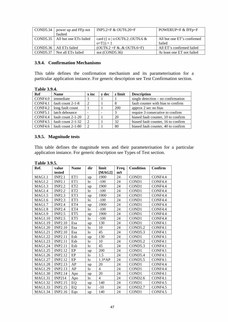
COND5.34 power up and FFp not faulted
INP5.2=F & OUT6.20=F POWERUP=F & fFFp=F
COND5.35 All but one ETs failed card ({ o | o:OUT6.2..OUT6.6 & o=T}) = 1
All but one ET’s confirmed failed
COND5.36 All ETs failed (OUT6.2 =F &..& OUT6.6=F) All ET’s confirmed failed COND5.37 Not all ETs failed not (COND5.36) At least one ET not failed 3.9.4. Confirmation Mechanisms This table defines the confirmation mechanism and its parameterisation for a particular application instance. For generic description see Test Confirmation section. Table 3.9.4. Ref Name x inc y dec z limit Description CONF4.0 immediate 1 1 1 single detection – no confirmation CONF4.1 fault count 2-1-8 2 1 8 fault counter with bias to confirm CONF4.2 long fault count 1 1 200 approx 2 sec no bias CONF5.1 latch debounce - - 3 require 3 consecutive to confirm CONF4.4 fault count 2-1-20 2 1 20 biased fault counter, 10 to confirm CONF4.5 fault count 2-1-32 2 1 32 biased fault counter, 16 to confirm CONF4.6 fault count 2-1-80 2 1 80 biased fault counter, 40 to confirm 3.9.5. Magnitude tests This table defines the magnitude tests and their parameterisation for a particular application instance. For generic description see Types of Test section. Table 3.9.5. Ref. value
tested Name dir limit
[MAG2] FreqmS
Condition Confirm
MAG1.1 INP2.1 ET1 up 1900 24 COND1 CONF4.4 MAG1.2 INP2.1 ET1 lo -100 24 COND1 CONF4.4 MAG1.3 INP2.2 ET2 up 1900 24 COND1 CONF4.4 MAG1.4 INP2.2 ET2 lo -100 24 COND1 CONF4.4 MAG1.5 INP2.3 ET3 up 1900 24 COND1 CONF4.4 MAG1.6 INP2.3 ET3 lo -100 24 COND1 CONF4.4 MAG1.7 INP2.4 ET4 up 1900 24 COND1 CONF4.4 MAG1.8 INP2.4 ET4 lo -100 24 COND1 CONF4.4 MAG1.9 INP2.5 ET5 up 1900 24 COND1 CONF4.4 MAG1.10 INP2.5 ET5 lo -100 24 COND1 CONF4.4 MAG1.19 INP2.10 Esa up 130 24 COND1 CONF4.1 MAG1.20 INP2.10 Esa lo 10 24 COND5.2 CONF4.1 MAG1.21 INP2.10 Esa lo 45 24 COND5.3 CONF4.1 MAG1.22 INP2.11 Esb up 130 24 COND1 CONF4.1 MAG1.23 INP2.11 Esb lo 10 24 COND5.2 CONF4.1 MAG1.24 INP2.11 Esb lo 45 24 COND5.3 CONF4.1 MAG1.25 INP2.12 EP up 200 24 COND1 CONF4.1 MAG1.26 INP2.12 EP lo 1.5 24 COND5.4 CONF4.1 MAG1.27 INP2.12 EP lo 1.3*AP 24 COND5.5 CONF4.1 MAG1.28 INP2.13 AP up 20 24 COND1 CONF4.4 MAG1.29 INP2.13 AP lo 4 24 COND1 CONF4.4 MAG1.30 INP2.14 Apo up 20 24 COND1 CONF4.1 MAG1.31 INP214 Apo lo 4 24 COND2.6 CONF4.1 MAG1.32 INP2.15 EQ up 140 24 COND1 CONF4.5 MAG1.33 INP2.15 EQ lo -10 24 COND2.7 CONF4.5 MAG1.34 INP2.16 Eqo up 140 24 COND1 CONF4.5
47

MAG1.35 INP2.16 Eqo lo -10 24 COND2.8 CONF4.5 MAG1.36 INP2.17 Eso up 130 24 COND1 CONF4.1 MAG1.37 INP2.17 Eso lo 10 24 COND5.9 CONF4.1 MAG1.38 INP2.18 FFm up 2800 24 COND1 CONF4.1 MAG1.39 INP2.18 FFm lo -100 24 COND1 CONF4.1 MAG1.40 INP4.5 FFp up 2800 24 COND1 CONF4.1 MAG1.41 INP4.5 FFp lo -100 24 COND1 CONF4.1 MAG1.42 INP2.20 PLm up 30 24 COND1 CONF4.1 MAG1.43 INP2.20 PLm lo 1 24 COND5.16 CONF4.1 MAG1.44 INP2.20 PLm up 25 24 COND5.17 CONF4.1 MAG1.47 INP2.23 OV up 40 24 COND1 CONF4.2 MAG1.48 INP2.23 OV lo 10 24 COND1 CONF4.2 MAG1.49 INP2.24 BV up 30 24 COND1 CONF4.2 MAG1.50 INP2.24 BV lo 10 24 COND1 CONF4.2 3.9.6. Rate tests This table defines the Rate tests for a particular application instance. For generic description see Types of Test section. The tests compare the difference of change in an input value to a limit. The value tested is |I – I-1| where I-1 is the previous reading. Table 3.9.6. Ref. value tested dir lim Frq
mS Condition Confirm
RATE1.1 |INP2.10 – INP2.10-1 | Esa Up 100 %/s 48 COND1 CONF4.1 RATE1.2 |INP2.13 – INP2.13-1 | AP up 2.6 psia/s 384 COND1 CONF4.1 RATE1.3 |INP2.18 – INP2.18-1 | FF up 2880 pph/s 48 COND1 CONF4.1 RATE1.4 |INP2.20 – INP2.20-1 | PLm up 15% 64 COND4.14 CONF4.1 3.9.7. Multiple Sensor Tests This table defines the multiple sensor tests for a particular application instance. For generic description see Types of Test section. Table 3.9.7. Ref. Value
tested Function dir lim Frq
mS Condition Confirm
MULT1.1 |INP2.10 – INP2.11|
|ESa-ESb| speed diff. up 5 48 COND5.10 CONF4.1
PRED1.2 |INP2.18 – INP4.5|
|FF-FFp| step check up 20 384 COND1 CONF4.1
MULT1.2 |INP2.12 – INP2.13|
|EP-AP| EPambient up 4.5 24 COND5.15 CONF4.1
MULT1.3 INP2.24 – INP2.23
BV-OR diode short up 0.2 96 COND2.18 CONF4.6
MULT1.4 INP2.24 – INP2.23
BV-OR alternator lo 0 96 COND2.19 CONF4.6
3.9.8. Latch (Pseudo) Tests These tests do not have a permanent state. I.e. once they confirm a detection they go back to the healthy state and start testing again. They are used for setting/resetting the PL latch when a condition is met and a value has been reached.
48

Table 3.9.8.
Ref. Value tested
Function dir lim FrqmS
Condition Confirm Action
MAG1.51 PLm Pllatch set up 25 48 COND4.11 CONF5.1 OUT6.28=T MAG1.52 PLm Pllatch set up 5 48 COND4.12 CONF5.1 OUT6.28=T ACT4.16 PLm Pllatch reset up - 48 COND5.13 - OUT6.28=F
3.9.9. Healthy Actions This table defines the healthy actions for a particular application instance. For generic description see Test Result Action section. Table 3.9.9. Ref. All these tests must be
healthy Definition Description Condition
ACT7.1 MAG1.1, MAG1.2, MAG1.3, MAG1.4, MAG1.5, MAG1.6, MAG1.7, MAG1.8, MAG1.9, MAG1.10
OUT5.1:= median (INP2.1 to INP2.5)
cET:= median (ET1..ET5)
COND1
ACT5.2 MAG1.19, MAG1.20, MAG1.21, MULT1.1, RATE1.1
OUT5.2 := IN2.10 cES:=ESa COND1
ACT5.3 MAG1.25, MAG1.26, MAG1.27
OUT3.1 := IN2.12 cEP:=EP COND1
ACT5.4 MAG1.28, MAG1.29, RATE1.2
OUT3.2 := IN2.13 cAP:=AP COND1
ACT5.5 MAG1.32, MAG1.33 OUT3.3 := IN2.15 cEQ:=EQ COND1 ACT5.6 MAG1.34, MAG1.35 OUT3.4 := IN2.16 cEQo:= EQo COND1 ACT5.7 MAG1.36, MAG1.37 OUT3.5 := IN2.17 cESo:= ESo COND1 ACT5.8 MAG1.38, MAG1.39,
PRED1.2, RATE1.3 OUT3.6 := IN2.18 cFF:=FFm COND1
ACT6.9 MAG1.42, MAG1.43, MAG1.44, RATE1.4
OUT3.7 := IN2.20 cPL:= 30 - PLm COND4.12
ACT5.10 MAG1.42, MAG1.43, MAG1.44, RATE1.4
OUT3.7 := IN2.20 cPL:= PLm + 30 COND4.11
ACT5.11 - OUT3.8 := IN2.29 cETo:=ETo COND1 ACT4.12 - OUT6.28 := F PL_LATCH:=F COND5.13 ACT4.13 - OUT6.33:=T,
OUT6.27:=T DUMP:=T, fOS:=T COND5.20
ACT4.14 - OUT6.33:=F DUMP:=F COND5.21 ACT4.15 MULT1.1, MAG1.40,
MAG1.41 OUT6.1:=F FREEZE:=F COND5.22
49

3.9.10. Temporary (Unconfirmed Failure) Actions This table defines the temporary actions for a particular application instance. For generic description see Test Result Action section. Table 3.9.10. Ref. Name At least one not
healthy but none confirmed
Definition Description Cond’n
ACT8.1 ET(x) failing MAG1.1, MAG1.2, MAG1.3, MAG1.4, MAG1.5, MAG1.6, MAG1.7, MAG1.8, MAG1.9, MAG1.10
OUT5.1:= median(healthy (INP2.1 to INP2.5)
cET:= median(healthy (ET1..ET5)
COND 5.37
ACT8.2 ESa failing MAG1.19, MAG1.20, MAG1.21, RATE1.1
OUT5.2 := lgv( INP2.10)
cES:=ESa-1 COND1
ACT8.3 ESb failing while used
MAG1.22, MAG1.23, MAG1.24
OUT5.2 := lgv( INP2.11)
cES:=ESb-1 COND5.23
ACT8.4 ESb failing, not used
MAG1.22, MAG1.23, MAG1.24
skip do nothing COND5.24
ACT8.5 ES diff failing
MULT1.1 OUT5.2 := lgv( INP2.10), OUT6.1:=T
cES:=ESa-1, FREEZE:=T
COND1
ACT8.6 EP failing MAG1.25, MAG1.26, MAG1.27
OUT3.1 := lgv(INP2.12)
cEP:=EP-1 COND1
ACT8.7 AP failing MAG1.28, MAG1.29, RATE1.2
OUT3.2 := lgv(INP2.13)
cAP:= AP-1 COND1
ACT8.8 APo failing while used
MAG1.30, MAG1.31 OUT3.2 := lgv(INP2.14)
cAP:= APo-1 COND5.25
ACT8.9 APo failing not used
MAG1.30, MAG1.31 skip do nothing COND5.26
ACT8.10 EQ failing MAG1.32, MAG1.33 OUT3.3 := lgv(INP 2.15)
cEQ:= EQ-1 COND1
ACT8.11 EQo failing MAG1.34, MAG1.35 OUT3.4 := lgv(INP 2.16)
cEQo:= EQo-1 COND1
ACT8.12 ESo failing MAG1.36, MAG1.37 OUT3.5 := lgv(INP 2.17)
cESo:= ESo-1 COND1
ACT8.13 FFm failing MAG1.38, MAG1.39, RATE1.3
OUT3.6 := lgv(INP 2.18)
cFF:= FFm-1 COND1
ACT8.14 FFp failing while used
MAG1.40, MAG1.41, OUT6.1:=T, OUT3.6 := lgv(INP 6.5)
FREEZE:=T, cFF:=FFp-1
COND5.27
ACT8.15 FFp failing not used
MAG1.40, MAG1.41, skip do nothing COND5.28
ACT8.16 FFd failing PRED1.2 OUT3.6 := lgv2(INP2.18)
cFF:= FFm-2 COND1
ACT8.17 PL failing MAG1.42, MAG1.43, MAG1.44, RATE1.4
OUT3.7 := lgv2(OUT3.7)
cPL:= cPL-2 COND1
ACT8.18 OV failing MAG1.47, MAG1.48 skip do nothing COND1 ACT8.19 BV failing MAG1.49, MAG1.50 skip do nothing COND1 ACT8.20 diode short
failing MULT1.3 skip do nothing COND1
ACT8.21 alternator failing
MULT1.4 skip do nothing COND1
50

Ref. Name At least one not healthy but none confirmed
Definition Description Cond’n
ACT8.22 ET failing (MAG1.1, MAG1.2, MAG1.3, MAG1.4, MAG1.5, MAG1.6, MAG1.7, MAG1.8, MAG1.9, MAG1.10)
OUT6.1:=T, FREEZE:=T, COND5.35
3.9.11. Confirmed Failure Actions This table defines the confirmed failure actions for a particular application instance. For generic description see Test Result Action section. Table 3.9.11.
Ref. Name All these tests must be healthy
At least one confirmed
Definition Description Cond’n
ACT13.1 ETx fault MAG1.1, MAG1.2, MAG1.3, MAG1.4, MAG1.5, MAG1.6, MAG1.7, MAG1.8, MAG1.9, MAG1.10
OUT5.1:= median(healthy (INP2.1 to INP2.5) OUTx:=T Where x is in range 6.2 to 6.6
cET:= median(healthy (ET1..ET5)), fETx:=T
COND5.37
ACT13.2 ESa fault, while ESb ok
MAG1.19, MAG1.20, MAG1.21, RATE1.1
OUT5.2 := IN2.11, OUT6.11:=T
cES:=ESb, fESa:=T
COND5.29
ACT13.3 ESa fault while ESb ko
MAG1.19, MAG1.20, MAG1.21, RATE1.1
OUT6.1:=T, OUT6.11:=T
FREEZE:=T, fESa:=T
COND5.30
ACT13.4 ESb fault MAG1.22, MAG1.23, MAG1.24
OUT6.12:=T fESb:=T COND1
ACT13.5 ES diff fault
MAG1.19, MAG1.20, MAG1.21, RATE1.1, MAG1.22, MAG1.23, MAG1.24
MULT1.1 OUT5.2:= max(INP2.10,INP2.11), OUT6.29:=T
cES:= max(ESa,Esb), fESd:=T
COND1
ACT13.6 EP fault MAG1.25, MAG1.26, MAG1.27
OUT3.1 := constant, OUT6.12:=T
cEP:=constant, fEP=T
COND1
ACT13.7 AP fault while APo ok
MAG1.28, MAG1.29, RATE1.2
OUT3.2 := IN2.14, OUT6.14:=T
cAP:=APo, fAP=T
COND5.31
ACT13.8 AP fault while APo ko
MAG1.28, MAG1.29, RATE1.2
OUT6.1:=T, OUT6.14:=T
FREEZE:=T, fAP=T
COND5.32
ACT13.9 APo fault MAG1.30, MAG1.31
OUT6.15:=T fAPo:=T COND1
51

Ref. Name All these tests must be healthy
At least one confirmed
Definition Description Cond’n
ACT13.10 EQ fault MAG1.32, MAG1.33
OUT3.3 := constant, OUT6.34:=T, OUT6.16:=T
cEQ:=constant, LOADSHARE:=T, fEQ:=T
COND1
ACT13.11 EQo fault MAG1.34, MAG1.35
OUT6.34:=T, OUT6.17:= T
LOADSHARE:=T, fEQo:=T
COND1
ACT13.12 ESo fault MAG1.36, MAG1.37
OUT6.18:=T fESo:= T COND1
ACT13.13 FFm fault at powerup or while FFp ko
MAG1.38, MAG1.39, RATE1.3
OUT6.1:=T, OUT6.19:=T,
FREEZE:=T, fFFm:=T
COND5.33
ACT13.14 FFm fault after pwrup & FFp ok
MAG1.38, MAG1.39, RATE1.3
OUT3.6 := IN6.5, OUT6.19:=T,
cFF:=FFp, fFFm:=T
COND5.34
ACT13.15 FFp fault MAG1.40, MAG1.41
OUT6.20:=T, fFFp:=T COND1
ACT13.16 FF diff fault
MAG1.38, MAG1.39, RATE1.3, MAG1.40, MAG1.41,
PRED1.2 OUT6.1:=T, OUT6.30:=T,
FREEZE:=T, fFFd:=T
COND1
ACT13.17 PL fault MAG1.42, MAG1.43, MAG1.44, RATE1.4
OUT3.7 := lgv2(OUT3.7), OUT6.21:=T,
cPL:= cPL-2, fPL:=T
COND1
ACT13.18 OV fault MAG1.47, MAG1.48
OUT6.24:=T, fOV:=T COND1
ACT13.19 BV fault MAG1.49, MAG1.50
OUT6.25:=T, fBV:=T COND1
ACT13.20 diode short fault
MULT1.3 OUT6.31:=T, fOR:=T COND1
ACT13.21 alternator fault
MULT1.4 OUT6.32:=T, fAL:=T COND1
ACT8.22 ET failing (MAG1.1, MAG1.2, MAG1.3, MAG1.4, MAG1.5, MAG1.6, MAG1.7, MAG1.8, MAG1.9, MAG1.10)
OUT6.1:=T, FREEZE:=T, COND5.36
--
52

SECTION 4. REQUIREMENTS DOCUMENT FOR CASE STUDY 3:MITA END-TO-END ARCHITECTURE REQUIREMENTS
4.1 Introduction
In this case study we wish to experiment with the construction of applications within given
frameworks and architectures which themselves are specified to provide certain kind of
fail-safe and dependency facilities.
Traditional methods of constructing such systems either proceed in a monolithic fashion
where the domain and architecture are inextricably linked or that the domain and architec-
ture are produced separately, in parallel and often without any linkage to each other. In this
latter scenario which we are primarily interested in we will explore the situations where
there are mismatches between the architectures and the application being constructed that
utilises those architectures. In this situation we will be able to better understand where
architectures and applications “break” and what repercussions this has on the overall reli-
ability and dependency properties of the system as a whole.
The role of this document is to outline the requirements process, the plan of work and the
initial set of informal (or even semi-formal) requirements for the MITA End-to-End archi-
tecture. Additional architectures will be made available during the course of the Rodin
project as detailed requirements become available.
The primary concern of this case study is not to produce an application but rather to
understand how architectures for applications can be formalised using the techniques
being developed inside Rodin.
The rationale of this is that architectures and applications are developed separately and that
it is often the case that applications need to be “forced” into certain architectures which
compromise certain desirable features of that architecture or application. A relevant con-
crete example is the addition of security features into existing architectures which can be
compromised easily because of the misalignment between the components - this can be
seen in some popular operating system environments. This in turn compromises the
dependability and fault-tolerance properties of those systems.
The goal is that once an architecture has been formalised this can then be used to assist in
understanding the constraints (and its suitability) of that architecture upon any application
that utilised that architecture; that is a suite of techniques can be developed to check con-
formance of an application or additional architecture against that particular architecture. It
may also be the case that a notion of conformance needs to be adequately discussed.
53

In this document we describe the work plan which includes description of the case study
components and proposed method, the current case study component requirements and
potential alignment and cooperation with other Rodin case studies.
4.2 Work Plan
The case study can be split into a number of phases:
• Construction and Formalisation of E2E Model
• Construction and Formalisation of Security Model
• Mapping of Security Model against E2E Model
• Construction of Simple Application utilising both E2E and Security Concepts
For the E2E and Security framework modelling stages we expect a demonstration of the
internal consistency of the models produced.
When mappings the security model against the E2E model we will have a number of
options regarding which parts of the E2E should take the responsibility for the various
security related functionality. It is also conceivable that the security model and the E2E do
not exactly fit - we then need to explore the ramifications of such a situation with regards
to the consistencies of the E2E and security models.
Finally the either the construction of a simple application or alignment/integration with
out Rodin case studies that utilise both the security and E2E frameworks will be made (in
particular Ambient Campus). Again this application itself must be internally consistent
and be consistent with the architectures/frameworks employed.
4.2.1 Requirements
We initially define requirements for two systems or architectures:
• MITA
• Security Model
The MITA End-to-End Architectural requirements are described in the document E2E
Concepts Reference Model (Ziegler). This document provides the current specification for
these concepts.
The security requirements are described later in this document.
Additional architectures will be introduced during the course of this project.
54

4.2.2 Concept Modelling Process
The first task is therefore to take the initial, unstructured requirements and produce a fina-
lised, structured requirements specification. The process proceeds as shown in figure 1
where we start with some unstructured requirements, proceed with the act of modelling
these producing a finalised structured requirements, a dictionary of the concepts and the
first conceptual model.
The process is highly iterative and relies upon the transient models produced during this
process being validated and checked against the existing unstructured and any structured
requirements produced. In a reflexive manner the models produced also act as a validation
of the requirements themselves.
Conceptual analysis means that we examine the concepts that we are discovering and
decided whether these concepts are relevant and can be well defined. We also check that
the concepts are being used consistently between the authors of the requirements and that
inconsistencies can be either unified or split so that no ambiguity exists in the concept.
We describe each of the work products, their internal structure and relationships involved
in this process. A graphical overview of this is shown in figure 2. Note that we use the ste-
FIGURE 1. Concept Modelling Process
55

reotype <<work product>> to denote which classes become the deliverables rather than
the elements that are contained inside them.
In figure 2 there are dependency arrows between certain elements. This is to show that
those elements do not have a well defined relationship in the usual sense but rather they are
to draw attention to that fact that, for example, the structured requirements depends upon
the unstructured requirements in some manner and to emphasise the tracing from one set
of work products to another.
We consider here that unstructured requirements are provided in the form of a document
containing a mixture of text, formulae, use cases and so on. In this form and without “engi-
neering” and validation the elements in this document have no intrinsic, first class model-
ling value and must not be used directly.
Unstructured requirements can only be used as input to this initial conceptual modelling
activity.
The structured requirements contain a list of requirements, a list of owners of those
requirements and the test cases. The minimum amount of information held in each
requirement is as follows:
• Requirements Identification
FIGURE 2. Work Product Structure
56

This is a number (usually) that uniquely identifies the requirement. No elaborateschema is required here just plain integer numbers.
• Short Title
A short title to introduce the requirements in a more meaningful way than just a num-ber is required. This must be kept as short as possible and should not contain anyinformation other than is necessary for a title.
• Owner
The name of the person who is responsible for this requirement. This is necessary sothat particular queries about the requirement can be traced back to the person who“invented” that requirements. There can only be one owner for each requirement.
• Description
This is a short description of that requirement. Requirements must be atomic innature and not discuss more than one particular topic or aspect.
4.2.3 Test Case
A test case is a description of a test that can be applied to the system to validate some par-
ticular piece of (usually) functionality. Test cases may be constructed from use cases or
some piece of non-functional information contained in the unstructured requirements.
Note that a test case here is a specialisation of a requirement and similarly a test case dis-
cusses certain concepts in the model and has an owner.
Use cases become test cases as we wish to emphasise that in an object oriented system a use
case describes a particular scenario related to how the system is going to be used.
Other test cases might be more non-functional in nature and express wishes such as that
the system must be theorem proved to ascertain some quality standard. This is particularly
the case with safety-critical type systems.
A dictionary contains a list of concepts that are discussed in the structured requirements
and are present in the conceptual model. The dictionary during this process serves to iden-
tify ambiguous and illdefined concepts.
The dictionary is sorted by the individual definitions it contains and the owners - this
allows a concept to appear more than once with more than one owner. If this happens then
analysis of the definitions can be made to ensure that the concept is being used by different
people consistently.
As we are performing object oriented analysis the conceptual model contains effectively
classes and relationships (associations, generalisation/specialisation and so on). Upon the
57

conceptual model there is a viewpoint that states that any view of this model is made using
the UML class diagram.
The conceptual model contains the same concepts as the dictionary but in a graphical form
and with more information about their internal structure, invariants across the concepts
and taxonomic structures etc.
The conceptual model may include supporting text and documentation to assist in the
reading of the model. This text however should not infer more information than is readily
accessible from the structured requirements, diagrams in the conceptual model and dictio-
nary together. The primary use of the supporting text is to document invariants, enumera-
tion types etc and their descriptions - those UML elements that tools find so difficult to
use.
For each test case there must be evidence of that test case being run against the models pro-
duced; in this case the conceptual model contains the evidence that it does adhere to all the
test cases in the requirements.
Additional tests such as the results of theorem proving, model checking or other verifica-
tions may also be present in addition to the tests cases provided in the requirements.
Also we may consider the generation of metrics from the model a type of test report; these
metrics deal with concepts such as class coupling, numbers of attributes/operations per
class, inheritance hierarchy depth and so on.
When using metrics, the results given at this stage of modelling contain little information
unless they are of extreme values. To give metrics value then it is important that metrics are
kept and then compared with other similar projects - do not compare an embedded safety-
critical system with a data warehousing project for example. These metrics are also used
later in the development process for comparison against other models. Do not use metrics
alone as evidence of quality design nor as evidence of the progress of a project. A project
with twice as many lines of code is not twice as good, better quality or contains twice as
much functionality - more often the reverse is true.
4.3 Ambient Campus
The Rodin CS5 Ambient Campus Case Study has obvious links with this case study. One
particularly interesting area is whether the system described in the Ambient Campus Case
Study corresponds to the architecture described in the MITA End-to-End Model.
This work will be undertaken later in the course of this project.
58

4.4 MITA End-to-End Requirements
Internally Nokia promotes a so-called End-to-End (E2E) view that shall comprise all
design work related to Mobile Internet services and technologies.
The E2E concepts reference model provides a baseline model for:
• Presenting the E2E architectures with common, defined terms and conventions
• Conducting E2E driven strategic and business analyses with a clear understanding ofthe relevant architectural concepts
• Analyzing and specifying E2E architectures in a wider context from terminals to serv-ers and peripheral equipment
• Analyzing and specifying E2E architectures in multiple functional layers from applica-tions to middleware and connectivity functionalities
The main target is to provide a baseline for a set of tools for case specific analyses and
design documentation. Please notice that the E2E concepts reference model does not pro-
vide any universal rule on how to design the details of any particular architecture.
The requirements presented here can be considered as being “unstructured” in nature.
4.4.1 E2E Segments
One way of structuring the E2E environment is done by the concept of E2E Segment. An
E2E segment denotes a part of the E2E environment into which the E2E environment can
be divided by narrowing to the scope of a class of devices but including anything from
hardware over electronics and system software up to general-purpose application software.
Any such instance of the concept of E2E Segment is a concept itself. Exactly three instances
of the concept of E2E Segment exist. They are called the concept of Server Segment, Mobile
Device Segment and Adjacent Device Segment. They are singularities. Each segment sepa-
rates out a mutually distinct part of the E2E environment.
R1: The E2E structure is divided into three segments: server, mobile device andadjacent device
R2: Each segment is mutually exclusive
Note that this division in segments essentially does not promote the E2E view. Each seg-
ment covers only a particular slice of the E2E view, but covers anything that contributes to
the processing performed in the segment from low-level transmission involved parts to
high-level applications interacting with a user.
However, with the help of the segments the "ends" of the E2E view can be made more
explicit. In almost any particular instance of an E2E view a mobile device from the mobile
device segment takes the end role at one side. This fact makes the mobile device and hence
59

the mobile device segment central to any E2E view. In some cases the other end is found
either in the server or adjacent device segment. In some cases the other end is yet another
mobile device, which, of course, belongs to the mobile device segment too.
R3: A physical device may play any particular role (server etc) at any point intime depending upon context.
4.4.2 The Mobile Device Segment
The mobile device segment covers anything closely related to any kind of device that the
end user can carry around and physically operate and interact with via certain UI capabili-
ties. The device is able to perform tasks requiring communication.
R5: A mobile device has one or more UI components
R6: A mobile device has one or more communication components (eg: GPRS,GSM etc)
It may use different means for communication depending the situation, but a connection
via some kind of mobile network is feasible almost everywhere, even when moving. Any
such device is called a mobile device. The mobile phone is the most commonly known
mobile device, but the class of mobile devices is not limited to mobile phones. Another
such instance is a personal digital assistance device (PDA). Any mobile device existing in
the world and any software executed by it is part of the mobile device segment including all
communication means any such mobile device has.
4.4.3 The Server Segment
The server segment covers anything closely related to a class of devices commonly called a
server because it contributes substantially to the production of a service.
R7: Servers provide services which are used by mobile devices
In most cases the server serves the production of a service in an on request manner.
R8: Services are provided as and when requested by a mobile device
The contribution is the storage and delivery of the content some service(s) is (are) based
upon. In other cases the server itself acts actively and issues requests. It is put in charge
fetching some particular data from somewhere and processing this data in order that a par-
ticular service can be composed.
R9: A server is responsible for the transmission and composition of the results ofcalling a requested service
60

A server operates unattended and has enough processing and communication capabilities
to communicate with many mobile devices (and other servers) at the same time at satisfac-
tory speed.
R10: A server can handle multiple, concurrent requests
When requested by a mobile device, the server, or more precisely speaking some particular
software installed on it for a certain purpose by somebody and continuously executed by it,
autonomously responds with the requested data. A significant amount of mobile devices
exist that potentially will perform such a request. A server is mostly stationary. It connects
with the Inter- or some Intranet or other network via a physically fixed connection. Any
server existing in the world and any software executed by it is part of the server segment
including all communication means any such server has.
4.4.4 The Adjacent Device Segment
The adjacent device segment covers anything closely related to a kind of device called an
adjacent device. Such a device can be in contact with one particular mobile device via at
least one sort of data connection for some time. Due to this connection this particular
mobile device can make use of the adjacent device for some particular purpose and hence,
in a logical sense, the adjacent device is close to this particular mobile device as the term
adjacent suggests. Only a small set of mobile devices can get in contact with a particular
adjacent device. The preferred, but not limited, way of how a mobile device communicates
with an adjacent device is wireless. This connection may be feasible only if the mobile
device is physically close enough and equipped with the technical communication means
that the adjacent device presumes for this communication purpose.
R10: An adjacent device is one that is physically close to a mobile device
R11: Adjacent devices may themselves be mobile devices
R12: An adjacent device is distinct from a server but might itself provide somekind of services
However, the class of adjacent devices includes also devices that only have some network
connection. In this case the mobile device connects to the adjacent device indirectly via
mobile network. An adjacent device remains at the same location for at least the time it is
performing some task(s) assigned to it. The class of adjacent devices includes many kinds
of devices that look differently and perform quite dissimilar tasks. Examples of adjacent
device are: a point of sale terminal able to perform a Bluetooth connection with a mobile
device; a VCR or set-top-box communicating with the mobile device via some particular
wireless proximity connection; the sauna switch with a fixed Internet connection that the
mobile device indirectly communicates with via mobile network. Any adjacent device
existing in the world and any software executed by it is part of the adjacent device segment
including all communication means any such adjacent device has.
61

4.4.5 E2E Layers
Disparate and in addition to the structuring by segments, the E2E environment is dissected
by the concept of E2E Layer. An E2E layer denotes a part of the E2E environment into
which the E2E environment can be divided by focusing on the items at a distinct level in
the range from hardware over system software up to general-purpose application software
but neglecting any natural boundaries between devices. Any such instance of the concept
of E2E Layer is a concept itself. Exactly four instances of the concept of E2E Layer exist.
They are called the concept of:
• Application Layer
• Enabler Layer
• Driver Layer
• Connectivity Layer
R13: The E2E Architecture is divided into four segments (as described)
The application layer, enabler layer and connectivity layer cover together the E2E environ-
ment completely and each of these three layers separates out a mutually distinct part. The
part of the E2E environment covered by the connectivity layer superimposes the part iden-
tified by the driver layer completely. However, some of the part of the E2E environment
covered by the connectivity layer remains outside of the driver layer. In contrast to the seg-
ments, each layer keeps the E2E view intact by stretching from E2E.
R14: The E2E segments are distinct and non-overlapping
The application layer covers the processing of the operations and interactions a user per-
forms or the content a user receives. The connectivity layer is devoted to the processing of
transmission of data. Anything may be found in here from special wire-based links over
any kind of wireless connection up to mobile networks. The so-called enabler layer aims to
include what neither is pure and plain transmission nor a direct contribution to the opera-
tions or interactions of a user. These layers, and in particular the driver layer, will be
described in more detail in the subsequent sections.
4.4.6 Application Layer
This model defines that any item in the application layer is an instance of the concept of
Application. In the narrowed scope of this model, an application denotes a unit of software
executing in an instance of the concept Mobile Device, Server or Adjacent Device.
R14: Applications execute on mobile or adjacent devices.
If we neglect for a moment all the nuts and bolts of the E2E environment and take a simple
holistic view, we can say an application performs some dialog with the end user, which is a
process of providing information to and taking input from the end user.
62

R15: Applications have a dialogue with the user via some UI.
Due to this dialog and directed by it, the executing application (or set of) produces the ser-
vice the end user desired. All the other stuff of the E2E environment is needed only to
make this dialog feasible and to support the delivery of this service.
Any of these applications we prefer to view primarily as an item of the segment it belongs
to. They are instances of the concept of Server Application, Mobile Device Application and
Adjacent Device Application respectively, which are specializations of the concept of
Application.
R16: The concept of application can itself be subdivided as according to the E2Esegments
Each of these specialized applications takes the narrowed view of one particular instance
of E2E Segment and is executed by an instance of the concept Mobile Device, Server or
Adjacent Device respectively. The development work on such an application is done from
the point of view of the single segment and for use in a particular device of that segment,
hence in a non-E2E view. However, a single project might combine the development of the
corresponding applications from different segments in some sort of a super-application
approach.
Any mobile device application performs some dialog with the end user by using the partic-
ular user interface capabilities of the mobile device. Any server application is able to per-
form the dialog with the end user only indirectly with the help of a mobile device
application dedicated to that purpose.
R17: mobile device applications interact directly with the user via some UI
R18: service applications interact only via an intermediate, for examplethrough the help of some mobile device.
R19: Users do not interact directly with server applications
This mobile device application may or may not contribute to the production of the ser-
vice(s). In any case, it will make use of the particular user interface capabilities of the
mobile device in order to process the dialog originating from the server application. The
underlying layers support this processing. In particular the connectivity layer provides
some particular data transmission mechanism. The same indirect manner of dialog applies
for any adjacent device application.
R20: Users can access applications on adjacent devices only via some interme-diate - similar to that of server applications.
However, a server application, and in particular if there is content stored by it, must be
installed and maintained by somebody, for instance the so-called service provider. For that
63

purpose, the server application is able to interact directly with the service provider. Also an
adjacent device application may interact directly with a user that is physically close enough
to the device. Those local interactions are not in the E2E view and thus not in the scope of
this model.
R21: Service Providers may interact directly with server applications
With the logical view of our model in mind we can say that the applications provide ser-
vices to each other and to the end user. A standard structure for these service relationships
and their directions exists. There, the services are labeled anonymously S1 to S5. These
labels are placeholders for any real service that might occur between the items connected
by the arrow. As you can see, any kind of application serves the end user (S1, S2 and S3). In
addition, a mobile device application serves an adjacent device application (S4) and a
server application (S5), because the physical provisioning of S1 and S3 requires such ser-
vices of a mobile device application. S4 and S5 are thus secondary services. Of course, the
complete physical performance of such a service requires some processing in the lower lay-
ers as well. In particular, the physical device-to-device data transmission occurs in connec-
tivity layer.
R23: All physical device-to-device data transmission occurs in connectivity layer
Of course, the model includes the option that an instance of a particular kind of applica-
tion serves another instance of the same kind. For instance, a server application may serve
another server application.
R24: Server applications may serve other server applications directly.
The two applications may or may not reside in the same device. The model ignores such
device boundaries. In particular, a mobile device application executing in one particular
device may serve a mobile device application executing in another device. S7 in Figure 7
might represent such a case.
This model defines the concept of Application and its specializations as concepts at meta-
level two. Hence, any particular instance of those concepts is a concept itself, but at meta-
level one. This fact allows developing models that are based on this reference model and
define their own concepts as they go to further detail. An example might be the concept of
Game modeled as a particular instance of the concept of Mobile Device Application. Tak-
ing further details into account such a model might define some specializations of the con-
cept of Game and only those specializations might become executing objects.
4.4.7 Connectivity and Driver Layer
This model defines that any item in the driver layer is an instance of the concept of Driver.
In the narrowed scope of this model, a driver denotes a unit of software executing in an
instance of the concept of Mobile Device, Server or Adjacent Device. A particular driver
makes a particular device capable to communicate with other devices via a particular data
64

transmission mechanism. However, in order that communication via this transmission
mechanism is finally feasible, this mechanism must actually be available in the connectivity
layer too. A driver could be made for and thus requires a physically distinct mechanism,
such as Bluetooth.
R25:Connectivity drivers provide the communications mechanism, eg: blue-tooth
Another driver, for instance a HTTP stack based one, may include the decision about the
data transmission mechanism only in a logical sense and thus defers the decision about the
physical means to the parts in the connectivity layer it is actually collaborating with.
This model describes only the general properties of the connectivity layer that is not cov-
ered by the driver layer. In that part of the connectivity layer the physical data transmission
from device to device takes place. Any kind of data transmission mechanism is potentially
used. The choice is limited only by the capabilities of the involved devices and the physical
availability of the desired mechanism at the actual point in time and space.
Some transmission mechanisms, such as Bluetooth, require only properly equipped
devices with the corresponding driver working in the driver layer in order to connect.
R26: Devices (of any kind) have various kinds of communication mechanisms
R27: Certain drivers use certain kinds of communication mechanism
R28: A device can not communicate via a driver if no suitable mechanism forthat driver is available on that device
Other transmission mechanisms, such as mobile network, require in the connectivity layer
a lot of additional infrastructure installed and properly working. Such infrastructure stuff
can optionally be connected to the Internet and in such a case the Internet might be used to
connect to the target device if that is on the Internet too. It shows the standard E2E envi-
ronment map with examples of specializations of the concept of Driver depending on the
data transmission mechanism they support and the segment they belong to. The possible
data exchange paths between them are labeled P1 to P4. Notice that P2 definitely and P3
optionally represent communication between two mobile devices.
If a device is equipped with a driver offering only one particular kind of transmission
mechanism, this device can communicate with other devices only if this mechanism is
actually available in the connectivity layer and this mechanism is also somehow able to
connect to the target device. If a device is equipped with a set of drivers each offering
another particular transmission mechanism and a few of these mechanisms are actually
available in the connectivity layer, this device must select which of them to use either by
querying the end user or based on some built-in preferences.
65

R29: If more than one driver is available then some selection method must beimplemented
R30: An ordering of preferences for particular drivers is required
R31: The failure of a driver means that it can be replaced “on-the-fly” if the com-munications path can be restored between the devices
The concept of Driver is a concept at meta-level two. Any particular instance of the con-
cept of Driver is a concept itself, but at meta-level one. This fact allows developing models
that are based on this reference model and define their own concepts as they go to further
detail. An example might be a concept of Bluetooth Driver modeled as a particular
instance of the concept of Driver. Taking further details into account such a model might
define some specializations of the concept of Bluetooth Driver and only those specializa-
tions might become executing objects.
4.4.8 Enabler Layer And E2E Service Enabler
Contrary to the other layers, the enabler layer is modeled primarily with the E2E view in
mind and thus considers the boundaries of the segments as secondary. The model defines
that the item we consider to view in the enabler layer is an instance of the concept of E2E
Service Enabler (E2E SE).
4.4.9 Formal Properties of E2E Segments
The concept of E2E Segment and Layer introduce quite many formal properties. These
details are more or less obvious for a reader, but must be stated in order to make the model
complete and allow further derivations correctly based on stated facts, such as the standard
E2E environment map introduced in the subsequent section.
Due to the disparate manner of the definition of the concept of E2E Segment and E2E
Layer, any particular layer covers some part of all three segments and any particular seg-
ment covers some part of all four layers. Thus, we can say the part of the E2E environment
covered by a particular segment and the part covered by a particular layer coincide pair
wise and define a subpart common to the particular segment and particular layer
R32: All constituents of the E2E architecture exist as both a segment and layercomponent
The three subparts in which the driver layer coincides with each of the three segments
cover completely and exactly the part of the E2E environment that the connectivity layer
has in common with any segment, i.e. the common subparts defined by coinciding the
driver layer with the segments are identical with the common subparts defined by coincid-
ing the connectivity layer with the segments. Therefore, the number of common subparts
is nine in total and not twelve, as the number of segments multiplied by the number of lay-
ers would suggest.
66

The subparts in which the application, enabler or driver layer coincides with each particu-
lar segment cover the application, enabler or driver layer completely and exactly. Or in
other words, anything that is part of the application, enabler or driver layer is also part of
exactly one particular segment. However, this is not true for the connectivity layer because
some of the part of the E2E environment separated out by the connectivity layer is outside
of any segment. This is exactly the part of the connectivity layer not superimposed by the
driver layer.
Furthermore, the model introduced here implies that for any layer any instance of a device
of the classes of devices specified by each of the three segments contains items belonging to
that layer. The layers can (and shall) be applied as top-level decomposition of these devices
as well. However, any such device covers that part of the connectivity layer only that the
driver layer embraces. The other part of the connectivity layer is outside of any such device.
These devices desire to exchange data with each other for the purpose of a service. Such
device-to-device data transmission always involves the connectivity layer, because it is the
only place where any kind of data transmission mechanism for that purpose resides. For
instance all infrastructure of the mobile network is part of the connectivity layer.
R33: All device-to-device communication is made via the connectivity layer.
4.5 Security Architecture
The Security Architecture requirements are at this time not available, however a basic out-
line of the architecture can be constructed.
Overall the security architecture is considered to be a separate aspect from the design of
any application and should be applicable to any application. The security architecture must
ensure as automatically as possible that the following objectives as defined in MITA are
achieved:
• Integrity
Prevention of errors or security lapses, eg: modification of information, storage of dataand corruption of the system as a whole
• Confidentiality
Prevention of the unauthorised disclosure of information to a third party.
• Authentication
Verification of users, security zones, trustworthiness of applications and data.
• Availability
Prevention of the unauthorised holding of information or resources.
• Intimacy
67

A user may treat or consider his or her own data as public but the security architecturemust prevent disclosure intentionally or unintentionally.
4.6 Base Requirements
S1: All applications will be certified by some authority (for example, VeriSign).This enables the integrity and source of an application to be verified.
S2: Applications communicate via messages. A message might be a datapacket over GPRS/GSM, Bluetooth or a coarse grained data packet such as XML(WebServices), SMS, E-mail etc.
S3: The “world” is divided into a number of zones of varying levels of trust andsecurity. Zones may be application based, user based or some other mecha-nism. It is conceivable that some data/application/etc might exist in anynumber of zones at any point in time.
S4: Users have different perceptions of trust for each zone. For example, zoneswhich do not process any information but just act as data carries trust all mes-sages while the user’s end device will.
S5: Messages or communication which cross zone boundaries must undergosome kind of certification or encryption to ensure that their validity/integrity isupheld.
S6: Messages may not pass between a zone of higher trust and a zone of lowertrust without some form of certification and/or encryption.
S7: Users may set up trusted channels of communication between applicationsin different zones. However this channel would then be restricted to communi-cation between those applications only. This would be achieved by certificationof the messages.
S8: A user may reduce their level of trust for any zone at any time. This makestheir overall perception of the world more secure.
S9: To increase their level of trust certification or validation of certification mustbe obtained. It is also possible that a zone’s level of trust could be increased butthis would entail that any zone communicating directly with it would considerthat zone to be less trustworthy.
S10: Any message that appears compromised or does not have a valid certifi-cate will be “sandboxed”
S11 Sandboxes are zones which are completely untrustworthy and can notcommunicate with any external zone.
S12: Users may share their views of zone security with other users
68

S13: If two zones are shared then their overall security or trust level is of the low-est
S14: If a zone is unshared then it returns to its original trust status. This mightcompromise security if that zone then contains uncertified applications or dataobtained from other zones originally. In this case the zone’s trust returns to thelowest level of trust for any received application or data.
S15: Users may customise access to their zones (see also S12) using certification
S16: The Security Architecture will be implementable within MITA
S17: Authentication may be made via certification, password or other suitablemechanism
S18: “Single Sign-on” must be provided as far a possible
S19: Messages which contain “secure information” (eg: passwords) must bereadable only in zones of equal or higher trust level than the information insidethe message is destined for.
S20: Messages may be time-stamped and have time dependent levels of trust.For example, a message containing financial results information will be initiallysecret (to some) but public to all after a certain time.
S21: In user terms, the security of applications and messages must be as trans-parent as possible and the management of the policies used as automatic aspossible
S22: Secure key and certification exchange/distribution must be possible withinthe architecture
S23: Key and certification exchange/distribution may be implemented by IKE(Internet Key Exchange) where possible (ie: non mobile)
S24: Acknowledgement of receipt (or not) of messages must be possible
S25: Authentication may be made over a number of levels.
Additional requirements will be made available during the course of the project.
69

© 2005 Praxis High Integrity Systems
1 INTRODUCTION
1.1 Purpose
This document states the requirements for the Civil Aviation Authority’s CCF DisplayInformation System, or ‘CDIS’ and includes requirements traceability.
It is intended that this document will be the starting point for prototyping and detailedspecifi cation work to be done during the implementation, and also for the acceptance tests theCAA will use to determine whether the CDIS system meets its requirements.
1.2 Readership
Readers who are unfamiliar with air traffi c control concepts will fi nd that chapter 2 provides afairly comprehensive introduction. Chapter 3 describes the functional requirements. Thesechapters assume that the reader is already familiar with air traffi c control terminology.
1.3 Background
CDIS is one of a number of systems being commissioned by the CAA which go to make up anew super-system for air traffi c control in the south east of England called the Central ControlFunction, or ‘CCF’. The main purpose of CCF will be to ensure the safe and orderly arrival anddeparture of flights to and from airports in the London Terminal Manoeuvring Area, or ‘LTMA’.
1.4 Special notations
Various special notations have been used in parts of this document:
• entity relationship diagrams;• data flow diagrams;
These are described briefly in the document, in the chapters where they are fi rst used. Theparticular variants of ER and data flow notations used are described in reference [2].
1.5 Structure of this document
Chapters 0 and 1 are document control and introduction respectively.
In chapter 2, we describe the environment in which the CDIS system will operate, using entityrelationship diagrams. Chapter 2 forms an essential part of the system specifi cation, and shouldnot be separated from it; readers new to the document intending to understand fully chapters 3and 4 should start by reading chapter 2.
In chapter 3, we describe the functions of the CDIS system; the chapter starts with a data-flowdiagram description of the primary functionality of the CDIS system.
70

© 2005 Praxis High Integrity Systems
2 DESCRIPTION OF THE CDIS ENVIRONMENT
The sections in this chapter are as follows:2.1 Introduction2.2 Data from airports2.3 Systems related to CDIS2.4 Users of CDIS and their roles2.5 CDIS devices
2.1 Introduction
This chapter describes the environment in which the CDIS system will operate.
2.1.1 How the description is divided up
Because the description is large, we have split it up into a number of themes. Each theme isdescribed in a separate section. See the top of the page for the list of themes.
In the chapter we make extensive use of entity-relationship diagramming to documentrelationships and invariant relations. Each theme’s section is arranged as follows:
1. A text overview.
2. An entity relationship diagram which highlights the most important entities in that part ofthe environment, and documents the relationships between the entities.
3. A text description of each entity, including descriptions of all its attributes; entity andattribute names are in bold type; the text describing the attributes is indented with respectto the entity description.
4. A description of each relation in the diagram; the actual relation is printed in italic type.
5. A list of additional invariant relations which cannot readily be captured in the entityrelationship diagram, with accompanying text descriptions.
6. A list of assumptions.
7. A list of questions.
2.1.2 Benefi ts of describing the environment
Describing the environment of CDIS serves a number of purposes:
1. We aim to specify and implement a system which closely reflects its environment, so thatchanges in that environment, which lead to changes requested in the CDIS software, arenaturally reflected in changes to the corresponding pieces of that software. Anunderstanding of the environment is a prerequisite of such an approach.
2. It provides an accurate picture of the boundary of the CDIS system, which is a vital partof specifying the system. An extensive environmental description has been put togetherfor the whole of the CCF by the MITRE Corporation. This chapter singles out those partsof the environment especially relevant to CDIS, and brings these up to date; it furtherdescribes those parts of the CDIS environment made up of other computer systems—.These fall within the boundary of CCF, and so are not described in the MITREdocuments.
71

© 2005 Praxis High Integrity Systems
2.1.3 The system/environment boundary
The environmental model considers the world of air traffi c control from the perspective of theCDIS system. Entities such as pages held by CDIS are internal to the system and disregarded bythe model. Other entities such as airports or controllers are clearly part of the environment andare included in the CDIS world model. Less obviously, the external computer systems whichinterface to CDIS also form part of its environment. For a further group of entities which relateto the system’s interfaces to the world, a choice must be made whether to class them as worldobjects or system objects. These entities, which include devices such as display devices, are saidto be on the system/environment boundary. In this specifi cation we choose to include peripheraldevices in the environmental model.
2.1.4 Understanding Entity relationship diagrams
The entity-relationship diagramming notation is described immediately below. Readers familiarwith E-R diagramming should skip the section and continue reading at the start of section 2.2.
Entity relationship diagrams show the relations between objects that are of interest. The objectsare called entities, and each is represented by a rectangular box on the diagram. Relationsbetween objects are represented by further, lozenge-shaped boxes, connected to the relevantentities by lines. The lines are annotated with numbers, or letters which stand for numbers.
A text description of the diagram’s entities and relationships is usually given and the importantattributes of each entity described. The range of values relevant to an attribute may also be given;this is referred to as its domain. Attributes whose names appear in square brackets are optional.
In the variant of the notation used here, each relation may strictly only be read one way. We hav eattempted to arrange the diagrams so that the direction of reading is always left-to-right or downthe page, though this is not always possible when attempting to avoid crossing lines.
A relation is read as follows: preface the fi rst entity name with ‘a’, ‘can’, or ‘each’. Next,examine the number on the line immediately adjacent to the second entity; if zero is one of thenumbers shown, preface the name of the relation with ‘may’, otherwise preface it with ‘must’.The name of the relation will usually be a verb; where it is not, preface the name with ‘be’.Finally, we need to add the second entity in the sentence; if there is a letter on the relevantrelation line by it, preface it with ‘one or more’; otherwise, preface it with whatever number isthere. Make it singular or plural according to the sense.
Practise on the examples shown at the end of this section. In example one, we show a relationbetween inbound queue and arrival. It should be read as ‘An inbound queue may have one ormore arrivals’. The ‘one or more’ corresponds to the letter ‘n’; the ‘may’ to the zero. Exampletwo should be read ‘A flight may be controlled by an ATCO’.
Subtyping: sometimes it is useful to differentiate two or more kinds of an entity. The entity (the‘parent’) is placed above, and the kinds of it which are to be differentiated are shown below inseparate entity boxes, each joined to the parent as shown in example three. A short cross-barhighlights the line to the parent entity. Note that the subtypes are exclusive: if an entity hasseveral subtypes, instances of one of those subtypes cannot also be regarded as one of the othersubtypes.
72

© 2005 Praxis High Integrity Systems
Entity relationship diagrams: examples
ATCO
flight
0,1
0<=n
0<=n
1
controlledby
arrival
have
inboundqueue
EG 2EG 1
user in role
engineerINTdirector
ASA
EG 3
2.2 Data from airports
There is a requirement for airport operational information such as meteorological data to becaptured and displayed on computer systems at airports and at LATCC. It is proposed thatrelevant information be stored on Airport Display Information Systems (ADIS), which will beinstalled at Heathrow, Gatwick, Stansted, and Luton airports.
The ADIS systems will have communications links to NAS and to CDIS. A subset of ADISinformation will be held by CDIS and displayed on support information pages, dynamicallyupdated by CDIS from data passed across the CDIS/ADIS interfaces. It will be possible tomanually overwrite the airport information from CDIS, though the manually entered values willonly remain until the next dynamic ADIS update. Information which has not been updatedwithin a parameter time is marked as old data. If after a further parameter period the data has stillnot been updated, it is deemed to be out of date. An indication of the status of the data will beshown when the data is displayed. A further possibility is that no value is available for display, aswill be the case immediately following an ADIS startup (and initially, during a CDIS startup).
73

© 2005 Praxis High Integrity Systems
The installation of an ADIS system, is a prerequisite for a free-flow airport, ie an airport atwhich take-off can occur without prior clearance from CCF controllers. For certain airports suchas Luton, the presence of an ADIS may still not allow free-flow on all routes, owing to Luton’sproximity to Stansted.
Data from airports stored by CDIS includes meteorological information and data concerning eachrunway at the airport.
2.2.1 Entity relationship diagram
1
0,1
1<=n1have
have ADIS
runwayairport
2.2.2 Entity defi nitions, including attributes
traceunit REQ.ADIS.EN
ADIS
An Airport Information Display System (ADIS) is a computer system for capturing anddisplaying operational information concerning an airport. ADIS systems are linked to NAS andto CDIS and a subset of the ADIS system information is held on CDIS and dynamically updatedvia the ADIS/CDIS interfaces. ADIS systems will also be the source of departures informationreceived by CDIS, though the data will normally be routed via NAS.
airport id
An airport has at most one ADIS and therefore the airport id provides a unique identifi er forthe ADIS entity. This is attribute models the relation: an ADIS must be owned by one airport.attribute.
74

© 2005 Praxis High Integrity Systems
traceunit REQ.AIRPORT.EN
airport
An airport, or airfi eld, is the point of departure or destination of a flight. It is the focal point of acontrol zone and as such always has an associated ATCO called the airfi eld controller, or towercontroller. Larger airports may also be assigned a LATCC fi nal approach approach director,called the FIN, or number two director.
airport id
This attribute uniquely identifi es an airport, possibly by using the airport name.
MAC id
The identifi er for the MAC which includes the airport. This attribute formalises the relation:airport is included in MAC.
domain: same as MAC.MACid.
ATIS letter
The Airfi eld Terminal Information Service (ATIS) letter is used by controllers when givingmeteorological information to aircraft. The ATIS letter changes every half hour to the nextletter, ie ‘b’ follows ‘a’ etc.
meteorological data
This consists of: average, maximum, and minimum wind speed in knots (or the value‘CALM’); average, maximum, and minimum wind direction (in degrees); serial number(alphanumeric); date/time; visibility (Km (?) or free text); cloud (4 values givingOKTAS/height or the single value ‘CAVOK’); temperature and dewpoint (numeric or freetext); QNH (mbar); QFE (mbar); remarks (free text); metar (free text); time of insertion (freetext). Note: ‘OKTAS’ are eighths of sky covered by cloud; ‘CAVOK’ indicates: Clear AndVisibility OK; QNH is the local sea-level pressure in mbar; QFE is the runway atmosphericpressure in mbar.
traceunit REQ.RUNWAY.EN
runway
An airport has one or more runways, which may be used for arrivals, departures, or both.Heathrow, for example, has two parallel runways which lie East-West. Depending on the winddirection, traffi c may land towards East (bearing 270) or towards West (bearing 090). The tworunways are distinguished as L(eft) and R(ight). The left runway is called either 09L or 27Laccording to the direction of traffi c flow. Similarly the right runway is called either 09R or 27R.
75

© 2005 Praxis High Integrity Systems
Heathrow also has a third, shorter runway, lying roughly North-South.
airport id
This attribute identifi es the airport served by the runway. Runways are uniquely identifi ed bythe airport id and the runway name. This attribute establishes the relationship: runway isowned by airport.
runway name
The runway name is based on its direction and position with respect to other runways, eg 27L,09R. The airport id and runway name uniquely identify the runway.
runway lights
This attributes consists of an on/off status for HIA, SHN, TDZ, CL, SL, SNOW, and PAPI,and an intensity value in the range 1 to 7.
runway status
This attribute defi nes whether the runway is being used for arrivals, departures, or both.
ILS category
This is a numeric value 1, 2, or 3, which denotes the type of Instrument Landing System (ILS)available on the runway.
IRVR at touchdown
Runway visual range at touchdown in metres.
IRVR at midpoint
Runway visual range at midpoint in metres.
IRVR at stop end
Runway visual range at stop end in metres.
2.2.3 Relation descriptions
traceunit REQ.AIRPORT.RUNWAY
airport to runway
An airport must have one or more runways. Note that this does not imply there is always arunway in use. Gatwick, for example, sometimes uses its main taxiway as a second runway whenthe runway is unavailable for maintenance at night. The inverse relation is: a runway must beowned by one airport.
76

© 2005 Praxis High Integrity Systems
airport to ADIS
An airport may have an ADIS. Conversely, an ADIS must be owned by one airport.
2.2.4 Additional invariants
traceunit REQ.AIRPORT.ADIS
1. A free flow airport must have an ADIS (or an equivalent system).
traceunit REQ.ADIS.NAS_LINK
2. An ADIS airport has a communications link to NAS.
2.2.5 Assumptions
1. Runway lights messages are repeated for each runway.
2. There is only one intensity value for each runway covering all the lights.
2.3 Systems related to CDIS
2.3.1 ADIS
The four main LTMA airports will be equipped with new computer systems which will be used togather operational data about weather, runways, etc., and also about departing flights. Thesesystems are the ‘Airport display information systems’ or ‘ADISs’. They will be equipped withperipherals at the airports, and will be interfaced to the systems at LATCC via the CAA’sCAPSIN X25 network. CDIS will receive airport and departure data from each operationalADIS.
The ADIS systems are used to capture and display airport operational information such asmeteorological data. A subset of this information will be displayed on CDIS support informationpages, dynamically updated from data received via the CDIS/ADIS interfaces.
The installation of an ADIS system, and hence of a link to NAS, is a prerequisite for a free-flowairport, ie an airport at which take-off can occur without prior clearance from CCF controllers.For certain airports such as Luton, the presence of an ADIS would still not allow free flow on allroutes, owing to its proximity to Stansted.
77

© 2005 Praxis High Integrity Systems
2.4 Users of CDIS and their roles
2.4.1 Overview
In this section we describe the various different sorts of role associated with the CDIS system,ranging from air traffi c control roles to supporting roles such as the engineering role thatencompasses the taking of daily and weekly backups, and maintaining the system. We considerthe information CDIS needs to have about the users of the system.
Users are the people who use CDIS. Roles are the CDIS-related jobs they perform. The carefulseparation of ‘user’ and ‘role’ may seem somewhat artifi cial; it is useful because it helps clarifythe requirements of the system:
• One user may be simultaneously carrying out more than one role.
• Certain roles, such as page editing, may be being carried out simultaneously by more thanone user.
• When expressing system requirements, it is a user acting in a role that is generally of mostinterest. For example, it is a user acting in a role who enters commands; and whose actionsmust be checked by the system to confi rm that the commands they are inputting are indeedvalid for that role (or the system prevents them from ever inputting invalid commands bynever offering them in the fi rst place).
The following roles have been identifi ed:
— (TMA) sector controller— editor— engineer.
Grouping of Roles
Certain functionality within the system is associated with a group of roles, rather than a singlerole. We adopt the following role groupings:
ATCO the TMA sector controller roles
non-ATCO everyone else
administrator an editor
The CDIS facilities may be divided up into a number of facility sets; various role groupings thenhave or do not have access to particular facility sets.
CDIS system security
Security is mainly provided by physical control of user access to the positions.
Roles
Below we identify the major CDIS roles.
78

© 2005 Praxis High Integrity Systems
traceunit REQ.ROLE.TMA
TMA TMA sector controller. There will be fi ve TMA sector controllers in each ofthe TMA North and TMA South, making 10 TMA sectors in all. CDIS’main function so far as these controllers are concerned will be the provisionof pages, and especially the departures and arrivals-sequence pages, as thisinformation is useful to the sector controllers provided it is suppliedsuffi ciently timelily.
traceunit REQ.ROLE.EDITOR
Editor Data editing staff. A role usually carried out by ATSAs. These staff areresponsible for entering the support information pages to the system. Theywork at user positions specially confi gured for this purpose.
traceunit REQ.ROLE.ENGINEER
Engineer The engineers staff the engineer position and system console positions, theformer round-the-clock. They carry out all the day-to-day tasks associatedwith maintaining a running system, including handlingremovable/consumable media, carrying out backups, carrying out scheduledpreventative maintenance, and taking action to restore system services afterany failures.
79

© 2005 Praxis High Integrity Systems
2.4.2 Entity relationship diagram
0,1
controlconsole
systemconsole
editingterminal
ATCOterminal
flightsupport
engineereditorTMAsectorcontroller
role userposition
use0<=n
2.4.3 Entity defi nitions
traceunit REQ.ROLE.EN
role
Many CDIS roles have been identifi ed. We use the word ‘role’ to mean a user carrying out aparticular job, so there are as many instances of, say, ‘engineer’ as there are people acting in thatrole.
role id
Identifi es the role.
domain: The roles are as listed in the text overview above.
New roles may well be needed from time to time—see the confi guration/adaptation section in
80

© 2005 Praxis High Integrity Systems
chapter 3.
traceunit REQ.USER_POSN.EN
user position
Any position on CDIS where a user inputs commands to the system, including commands enteredon a PSD. Includes all ATCO suites, editing terminals, and engineer terminals.
There is some duplication of equipment required within user positions, and some duplication ofpositions.
traceunit REQ.ENGINEER.DUPLICATION
The following positions are duplicated for extra reliability:
• engineer position; (the system console is not required to be duplicated, but there should beanother console which can carry out the system console role).position id
Identifi es the operator station.
The sub-types of user position are listed below:
traceunit REQ.POSN.ATCO
ATCO suite
The standard ATCO furniture suite. The suites are arranged in one of two banks one on each sideof the CCF room. An ATCO suite will have at least the following user equipment:
• an EDD, a PSD;
suite id
Identifi es the suite; used by the supervisors, initially to confi gure the system, and, later, toreconfi gure either for bandboxing or in response to suite failures.
81

© 2005 Praxis High Integrity Systems
traceunit REQ.POSN.EDITOR
editing terminal
Used by a supervisor or an ATSA to input support information pages and related commands.There will be several editing terminals on the working system.
traceunit REQ.POSN.ENGINEER
engineer position
One is sited in the CCF adjacent to the engineering area, and one in the CDIS CCPS machinearea (‘equipment room’). Staffed round-the-clock by engineering staff; however these staff hav eother responsibilities and a mechanism will be needed to attract their attention to importantev ents.
traceunit REQ.ENGINEER.FUNCTIONS
The engineer’s position will be used for quite a large number of subsidiary system functions,including:
• system (re)start and shut down• page/TRQ confi guration• back-ups/restores
traceunit REQ.POSN.SYS_CONSOLE
system console
Essentially a system boot and operating system console. Not staffed round-the-clock. Thesystem console is to support the following functions:
• re-boot system
82

© 2005 Praxis High Integrity Systems
2.4.4 Relation descriptions
user to role
A user may act in one or more roles. Reading the relation the other way,
traceunit REQ.ROLE.USERS
A role may be acted out by one or more users. Certain sector control roles may in the future beconducted by two or three cooperating ATCOs.
role to user position
A role may be assigned to a user position. Notice that, since we mean by ‘role’ a user acting in agiven capacity, and since a user can be in only one place at a time, a role can be assigned to atmost one user position. The inverse relation is:
traceunit REQ.USER_POSN.ROLES
a user position may be assigned many roles.
2.4.5 Additional invariants
traceunit REQ.ROLE.SUITABLE_POSN
1. Editors must be assigned to their respective terminal types. TMA sector controller rolesmust be assigned to ATCO terminals. Engineer roles must be assigned to the engineerposition.
traceunit REQ.USER.MULTIPLE_ROLES
83

© 2005 Praxis High Integrity Systems
2. If a user is acting in a number of roles, those roles are all assigned to the same userposition.
2.5 CDIS devices
2.5.1 Overview
Peripheral devices such as keyboards, and displays are on the boundary between the CDISenvironment and the system itself. These devices are suffi ciently important to merit inclusion inthe CDIS world model. Here we show the kinds of device required by CDIS and describe theirrelationship to user positions.
2.5.2 Entity relationship diagram
mouse
0<=n1deviceequipped
withuser position
PSDkeyboardEDDprocessor
2.5.3 Entity defi nitions
traceunit REQ.DEVICE.EN
device
This entity includes EDDs, keyboards and PSDs.
device_id
Unique device identifi er.
84

© 2005 Praxis High Integrity Systems
traceunit REQ.PROCESSOR.EN
processor
Each non-console user position will have at least one processor. At certain positions theprocessor will be duplicated either for reasons of reliability or increased functionality.
traceunit REQ.EDD.EN
EDD
EDDs are used for displaying pages of information. The screen will be divided into a maindisplay area, for full-size pages, and a status area at the bottom, used for viewing broadcastmessages.
traceunit REQ.KEYBOARD.EN
keyboard
Ke yboards are used for editing purposes.
traceunit REQ.MOUSE.EN
mouse
Mice are used for editing purposes.
traceunit REQ.PSD.EN
PSD
A PSD (Page Selection Device) is a keypad used for selecting pages for display.
85

© 2005 Praxis High Integrity Systems
2.5.4 Relation descriptions
user position to device
A user position may be equipped with one or more devices. Positions other than consolepositions have at least a processor.
traceunit REQ.EDD.USER_POSN
Positions other than the system console have at least an EDD. The inverse relation is: devicesmay be used at one user position.
2.5.5 Additional invariants
traceunit REQ.DEVICES.ATCO
1. ATCO terminals have at least a processor, an EDD, a PSD.
traceunit REQ.DEVICES.EDITOR
2. Editing terminals have at least a processor, EDD, keyboard and mouse.
traceunit REQ.DEVICES.SYS_CONSOLE
3. The system console has no devices.
traceunit REQ.DEVICES.ENGINEER
86

© 2005 Praxis High Integrity Systems
4. The engineer positions have at least a processor, an EDD, a a mouse and a keyboard.
We intentionally avoid specifying exact confi gurations, to allow for the possibility of evolution inthe way positions are set up for different roles.
87
© 2005 Praxis High Integrity Systems
3 FUNCTIONAL REQUIREMENTS FOR CDIS
In this chapter we describe the functions which the CDIS system will perform, including alloperations to be offered to users of the system. Considerations of "human factors" and therequirements for the MMI are outside the scope of this study, but are an important part of thework to be done before implementation.
The chapter is divided into the following sections:
• Introduction• Primary function• Error & exception handling• System confi guration/adaptation
In the introduction we provide a requirements summary, and give guidance on the Yourdonnotation used in other sections. In the primary function section, we describe the primaryfunctions to be provided by CDIS, presented as a levelled set of Yourdon data flow diagrams.The section addresses all normal functioning of each CDIS user and automatic facility.
3.1 Introduction
In this section we state the purpose of the functional requirement, its scope and intendedreadership, we describe how the requirements were gathered, we give a short summary of therequirement, and an introduction to the Yourdon modelling notation used in the remainder of thechapter. We also explain the tie-up with the environmental modelling of the previous chapter.
3.1.1 Purpose of Functional Requirement
The functional requirement has been put together to:
• be the basis for a fi xed price proposal for undertaking the implementation of the CDISsystem;
• form the cornerstone of the implementation project. To this end the requirement must:
— describe the system to be designed and built;— form the basis for acceptance testing of the system by the CAA;— be the main source of information for the user manuals to be written for the system.
3.1.2 Scope
From the above it is evident that the readers of the requirements specifi cation will have widelydiffering technical backgrounds. Some diffi cult decisions have had to be made over what to leaveout and what to include in the description.
CDIS is a new system to the CAA—the SIRS system being the nearest thing to CDIS at LATCCto date—so at this stage it is not possible to work out all the uses CAA staff will make of thesystem, and therefore to identify completely the areas where a degree of flexibility is important.We perceive it as important that a certain amount of time be included in the implementationproject for prototyping.
The requirements set out in this document represent our best understanding of the CDISrequirements as presented to us in documents (references [1] to [9] inclusive, and also [12] to[14]) or by members of the CAA CDIS requirements liaison team. The scope of the requirementsdescription in this document has been limited chiefly by lack of time to step through all the
88

© 2005 Praxis High Integrity Systems
requirements suffi ciently thoroughly; but also by lack of fully agreed interface defi nitions (ICDs)and by inadequate time to carry out prototyping in the area of user interfaces. A substantialamount of detailed specifi cation work remains to be done at the start of the implementationcontract.
3.1.3 Short Summary of CDIS Requirement
CDIS is a distributed information, command and control system, with various important ancillaryfunctions. The purpose of CDIS is to aid Air Traffi c Control Offi cers in their control of air traffi c,and particularly of arrivals and departures, in the London TMA. CDIS is one of a number ofcooperating systems which make up a super-system, the Central Control Function or ‘CCF’, withthis common purpose.
Support Information Pages
Air traffi c control offi cer users of CDIS select pages for viewing on high resolution colourdisplays. Pages contain text and/or graphical information, some of which may be updated in realtime. CAA supervisors and support staff create the pages in isolation from the ATCO part ofCDIS using special editor programs provided with the system. Release of pages into the ATCOoperational part of CDIS may be delayed, allowing editing of pages to take place days or evenweeks in advance.
Airport Data
CDIS receives liv e feeds of airport data from information systems (ADISs) situated at the free-flow airports Heathrow, Gatwick, Stansted and Luton. This data is displayed on some of thesupport information pages described above. It is updated in real time; where data is unavailablefrom an airport, CDIS supervisors/editors may enter airport data manually to the system. Dataentered in this fashion is specially highlighted to make users aware that it is not live data.
3.1.4 How the requirements are presented
The primary requirements are presented as a levelled hierarchy of Yourdon data flow diagrams. Itis assumed that readers of the document are familiar with the data flow diagram notation.
The bulk of the requirements defi nition is held at levels 2, 3 and 4 (taking the fi rst breakdown ofthe context diagram as level 0). Each major level 2 or 3 subsection defi ning requirements isdivided into the following subsection parts:
• a list of principles which underly the system requirements in that area;
• a text overview of the requirement;
• a data flow diagram or diagrams with accompanying text description;
The DFDs provide a process-oriented view of CDIS. It has been possible to model only afraction of the processes in the limited time available for the study.
3.2 Primary Function
In this section we describe the primary functionality of the CDIS system by means of a levelledset of data flow diagrams, with additional text description. The diagram hierarchy is presentedtop-down. The description is chiefly process-oriented.
The fi rst two data flow diagrams are simplifi ed overall views of CDIS. The fi rst, the context
89

© 2005 Praxis High Integrity Systems
diagram, shows the main flows of data into and out of the system. Apart from the many differenttypes of user command & display input/output, it may be seen that the system also interfaces toother computer systems including ADIS.
Context Diagram
user_trans_data_io
CDIS_system
user_control_io
tape_archive
ADIS_CDIS_msg
tape_drive
ADIS
user_page_io
user
0
90

© 2005 Praxis High Integrity Systems
The Level Zero Diagram
user_trans_data_io CDIS_time
user_control_io
ADIS_msg
trans_data_msg
control_system
tape_archive
ADIS
user_page_io
tape drivetrans_data_item
trans_data_item
user
maintain_trans_data
trans_data
maintain_and_dis_play_CDISpage
1
3
2
In the level zero diagram, we show the main breakdown of description of functionality into threeelements:
1. system control;2. support information page display and editing;3. the maintenance of transient data;
Only one store is shown at this top level description: the transient data store. This is a piece ofsystem state modifi ed on receipt of transient data update messages from NAS or ADIS, and allparts of which may be confi gured into any of the support information pages for display to theusers of the system.
The other data flows are as for the context diagram.
1 Control System
This part of the specifi cation describes many of the ancillary functions offered by CDIS.
Text Overview
Under engineering_functions we have gathered together facilities offered the engineer users ofCDIS to carry out routine operation and maintenance of the system.
91

© 2005 Praxis High Integrity Systems
Data flow diagram 1, with description
trans_data_msg
tape_archive
tape drive
CDIS_time
engineer_io
engineering_functions
ADIS_CDIS_msg
ADIS
manage_system_interfaces
user
.2
.1
Process description:
1.1 manage_system_interfaces
input/outputs:
ADIS_CDIS_msgInputs from and outputs to ADIS.
outputs:
trans_data_msgA processed transient data message updating the CDIS transient data store.
1.2 engineering_functions
input/outputs:
engineer_ioAll engineer user commands and responses.
inputs:
outputs:
CDIS_timeCDIS-internal time distributed to other parts of the system.
tape_archiveSystem backup archive data to tape.
92

© 2005 Praxis High Integrity Systems
1.1 Manage system interfaces
In this sub-section we address the requirements of managing the most important CDIS interfaces,to the various ADIS systems.
Principles
• Detailed non-application-level information will be supplied in separate architecture anddesign documents. Here we supply only an abstract description of the application layers ofthe interface.
• Each ADIS supplies CDIS with airport data messages of various kinds.
There are no differences between ADIS systems signifi cant to CDIS. Accordingly, we restrictour attention to an ADIS system assumed to represent any of the actual ADISs.
Text Overview
The ADIS interface forms a major part of the CDIS environment, as described in chapter 2.CDIS receives transient data from ADIS, which it stores internally, and which it offers fordisplay on support information pages as confi gured by the page editors and system supervisors.
From the ADIS systems, CDIS receives data about runways and airports, includingmeteorological data. The full list of messages is given in the ADIS-CDIS ICD [1].
Data flow diagram 1.1 with description
trans_data_msg
ADIS_trans_data_msg
ADIS_CDIS_msg
ADIS
manage_ADIS_iface
.
.2
93

© 2005 Praxis High Integrity Systems
Process description:
1.1.1 manage_ADIS_interfaceThe process specifi cation for the CDIS side of the CDIS:ADIS interface.
inputs:
ADIS_CDIS_msg
traceunit REQ.SYS_IF.ADIS_CDIS_MSG
The generic input from an ADIS.
outputs:
ADIS_trans_data_msg
traceunit REQ.SYS_IF.ADIS_TRANS_DAT A_MSG
Airport data.
The main input from ADIS; transmitted by the interface management software to theairport transient data handling sub-system. Refer to the transient data managementdescription in process 2 for further details on how transient data is handled.
1.2 Engineering functions
Under engineering functions we group together a number of facilities required by the engineerusers of CDIS to operate and maintain a fully serviceable system. We defi ne facilities for:
• system start-up and shut-down;• archive management.
Principles
traceunit REQ.SYS.STARTUP_RAPID
94

© 2005 Praxis High Integrity Systems
• System start-up/start-over must be very rapid. Only essential functions should be performedduring the start-up process.
• Some data are required to be stored on tape:
i. Backups of all disc-based data (whether this is done using the operating system orthe application is not a concern of this specifi cation). Backups are distinguishedfrom archives in that they are always copies of data currently on disc, kept as asafeguard against loss or corruption of the disc-based data. Archives on the otherhand are kept to save disc space and the archived material is usually deleted fromdisc following the copy to tape.
Text Overview
Start upHow the system is initialised to the point where it is in a suitable state to start up the CDISapplication (ie power-up, and probably also some separate operating system re-boots) is notspecifi ed functionally. This section explains the engineer facilities to start up, start over, and shutdown CDIS, given an operational LAN, processor and operating system infrastructure.
traceunit REQ.SYS.INITIAL_STARTUP
Initial start up is carried out at the system console. Start-up and start-over differ:
traceunit REQ.SYS.STARTUP
• Start up of CCPS is divided into cold start and warm start. The only difference is where thestate of the CCPS is derived from. Neither kind of start up will preserve transient data.Adaptation can be changed on either kind of start up.
• Cold start, also called start from snap, will involve loading a previously saved snapshot of theCDIS state from a tape. From then on, it will be similar to warm start except for the way outof step PS/2s are treated: while on a warm start PS/2s are not started immediately if theirpages are out of date, on a cold start, all healthy PS/2s will be started even if their pages areout of date. The facility will rarely be used, and will probably follow an operating-system re-boot of the whole CDIS processor population.
95

© 2005 Praxis High Integrity Systems
traceunit REQ.SYS.STARTOVER
• Start up of a workstation will be independent of start up of the CCPS and can be done at anytime. If CDIS is running it will automatically be incorporated into the system if it is enabled.
• A warm start will only be possible if CDIS was shut down in good order. It will involvestarting from the state immediately before the last shutdown. There will be protection againstthis being attempted if there was no successful shutdown, for example if CDIS failed. This isnecessary because the state of CDIS is not reliable in such circumstances.
ShutdownShutdown will be initiated at the control console.
Archive management
Backups
As part of CDIS normal operation, engineers will have to make periodic backups of all data heldon disc on the system. No automatic backups will be made.
traceunit REQ.TAPE.NO_OVERWRITE
The system shall check for mounting of already-written tapes, and not overwrite these.
96

© 2005 Praxis High Integrity Systems
Data flow diagram 1.2 with description
.archive_req
CDIS_time
CDIS_time
maintain_CDIS_time
CDIS_dbase_archive_input
tape_archive
tape drivestartup_or_shutdown_req
startup_or_shutdown_report
CDIS_database
manage_archives
user
startup/shutdown
.2
.3
.1
Process specifi cation:
1.2.1 startup/shut-down
inputs:
startup_or_shut-down_reqRequest by the user to start up, start over, or shut down.
traceunit REQ.SYS.STARTUP_VALID
Start-up invalid unless the system is in a shut-down state.
CDIS_timeRequired as input for broadcast and logging purposes.
outputs:
97

© 2005 Praxis High Integrity Systems
startup_or_shut-down_reportOutput about the start-up, start-over or shut-down.
1.2.2 maintain_CDIS_timeThis process specifi es how the system manages time. Details are not relevant to theRodin subset.
outputs:
CDIS_timeAs used throughout the CDIS system.
1.2.3 manage_archivesThis process specifi cation covers all aspects of managing the archives.
inputs:
archive_reqA backup request issued by the user.
CDIS_dbase_archive_inputState of the database to be saved for a cold start.
outputs:
tape_archiveThe archive output to tape.
2 Maintain and display CDIS page
Principles
• Accessing support information is an important, but relatively small part of an ATCO’sactivity.
• Access to support information should be simple, using as few key strokes as possible.
• Ease of use of the system is more important than flexibility.
• Full page displays are required for certain static information such as maps, but are notrequired for the various kinds of dynamically updated information.
• Transient data on display is updated in real time as new information becomes available toCDIS.
• It should be possible to display different combinations of departure information, airportinformation, inbound queue information, and other, static data on a single EDD. This isachieved by using half pages for transient data.
• There are suffi ciently few half page combinations that they should be set up by the supervisor,rather than confi gured by the ATCOs at their suites.
• Scrolling of pages is unacceptable. Where there is too much information for a page or halfpage, the data should be divided across several pages.
• There is a requirement to edit pages and withhold publication of the new version until a futuredate. It is not required, however, to hold more than one pending version of a page.
98

© 2005 Praxis High Integrity Systems
• There is no requirement to share information, other than transient data items, among halfpages. Full, split screen pages may, howev er, share half pages.
• There is a need to use templates for defi ning transient data pages. The template for transientdata, called a layout descriptor, specifi es the position and origin of each transient data itemand defi nes a text or graphics background.
Text Overview
One of the primary functions of CDIS is to make readily available to air traffi c controllers andtheir supervisors a variety of textual and graphical information in the form of pages, which canbe viewed, one at a time, on the display terminal at a control suite.
traceunit REQ.PAGE.VIEW_POSNS
All information pages can be viewed at positions equipped with an EDD and a keypad pageselection device (PSD). In addition, all pages can be viewed at editing terminals which areequipped with keyboards.
traceunit REQ.PAGE_EDIT.POSNS
Pages can only be composed or altered at editing terminals, however. The PSD allows all pagesto be selected by page number and a subset to be retrieved by fastkey access. There are defaultfastkey to page mappings defi ned for each user role which can be redefi ned by the CCFsupervisor.
It is envisaged that the EDD’s will display two kinds of page: full screen pages, and split screenpages. Full screen and split screen pages, will have predefi ned text or text + graphics contents.The CDIS graphics will support the "free-hand" drawing capability required to draw such thingsas coastlines.
Split screen pages differ from full screen pages, in that the page is made up from two half pagedefi nitions, either two landscape or two portrait half pages.
The information displayed on pages can be categorized as either fixed data, also referred to asstatic data, or transient data, alternatively called dynamic data.
traceunit REQ.PAGE.FIXED_DAT A_UPDATE
Fixed data records information which is updated relatively infrequently and always manually.
99

© 2005 Praxis High Integrity Systems
Transient data on the other hand is normally updated in real-time by CDIS in response to updatemessages received from other computer systems. The data may be displayed graphically, forexample showing a compass rose and pointer to indicate the wind direction at a particular airport.Transient data includes general airport information.
traceunit REQ.TRANSIENT_DAT A.AGING
Transient data which is not updated within a parameter time will be marked by CDIS as old data,and after a further parameter period relabelled as out-of-date. This ‘ageing’ of transient data willbe reflected by pages displaying the data.
traceunit REQ.TRANSIENT_DAT A.MARK_MANUAL
Items of transient data will also be marked to indicate if their current value was entered manuallyor if no value is available. Airport operational information, at least, will sometimes be manuallyoverwritten at editing terminals that are assigned the appropriate privilege. It will also bepossible to defi ne as transient data, information which is never updated dynamically by CDIS, butonly by manual input. This will permit emulation of transient data sources such as an ADISsystem.
traceunit REQ.TRANSIENT_DAT A.FLAG_CHANGES
There is a requirement for CDIS to be able to flag changes to selected transient data items using,say, inv erse video. Particularly important changes, such as changes in atmospheric pressure willneed to be flagged and possibly acknowledged by all positions displaying the information (CQF307). Certain items of meteorological data may need to be flagged if they vary outside aspecifi ed range. Flagged data requiring acknowledgment will remain flagged at a consoleposition until acknowledged by all relevant controllers.
Whereas static pages can be edited on-line, dynamic pages must be validated off-line to ensurethat no transient data is obscured as a result of using an inappropriate layout defi nition. Onlypages having valid defi nitions can be released for on-line display.
A valid new page, or a new version of an existing page, can either be released immediately fordisplay or held on a timed release queue (TRQ) and made available at a specifi ed date and time.This allows information to be entered well in advance of its required release date, and the pageediting workload can be spread over a period of time. Static or dynamic information pages canbe held on the queue, dynamic pages becoming active only when released. Full pages or half
100

© 2005 Praxis High Integrity Systems
pages can be queued. Only one version of a page may be held on the TRQ.
In general, ATCOs are not informed of the release of new pages, or the update of current pages.However, messages to this effect can be broadcast and displayed in the status area of the screen.
Entity-relationship description
Note that a split screen page is always associated with two half pages.
Entity relationship diagram:
0<=n
0<=n0<=n
0<=n
userposition
2
half page
includes displayshave
split screenpage
full screenpage
1<=n0<npage displayable
at
.3
layout descriptor
transient data item
0..1
Entity defi nition, including attributes:
page
CDIS support information may be formatted and displayed on one or more information pages.They are the chief means by which ATCOs access CDIS information. Pages are viewed atterminals whose display area is divided into an upper and a lower logical screen. The upperscreen, which occupies most of the viewing area, displays at one time a single page. The lowerscreen is used to display broadcast messages. A keypad device, called a Page Selection Device(PSD) can be used to select any page for display.
page id
This attributes uniquely identifi es a page. Note that the page number does not provide aunique key since there may be several versions of some pages.
domain: The domain of this attribute is arbitrary, but could be based on the version andpage number.
101

© 2005 Praxis High Integrity Systems
traceunit REQ.PAGE.NUMBER
page number
Pages are numbered. There may be up to three versions of a page with a given pagenumber: a current version, a backup version, and a version on the timed release queue.
traceunit REQ.PAGE.SELECTION
An ATCO uses his PSD to select by page number the current version for display. Theinformation displayed on a page corresponding to a given number is defi ned by data entrystaff or the CCF supervisor.
domain: The natural numbers, starting at 1.
version
traceunit REQ.PAGE.CURRENT_VERSION
For a giv en page number there is one version of the page available for selection at alldisplay terminals. This is called the current version.
traceunit REQ.PAGE.BACKUP_VERSION
There may also be a backup version. This is created from a current version when it isedited to create a new version.
traceunit REQ.PAGE.PENDING_VERSION
A third possible version of a page is referred to as pending. A page can be edited, thenheld as pending on the Timed Release Queue (TRQ).
102

© 2005 Praxis High Integrity Systems
traceunit REQ.PAGE.TRQ_RELEASE
The current and backup versions are unchanged until, at a preset date and time, thecurrent version becomes the new backup and the pending version is removed from theTRQ to become the new current version. Note that it is possible for all three versions of apage to exist at once.
traceunit REQ.PAGE.UNIQUE_ID
A page is uniquely identifi ed by its page number and version attributes.
traceunit REQ.PAGE.VERSION
domain: The page version may be current, backup, or pending.
[release date]
traceunit REQ.PAGE.RELEASE_DATE
The release date attribute specifi es the time and date for a pending page to be removedfrom the TRQ to become the new current page.
domain: This attribute consists of a date and a time, or the value null for pages not on theTRQ. Under normal circumstances the date will be a later date than the current systemdate.
full screen page
traceunit REQ.PAGE_TYPE.FULL_SCREEN
page id
103

© 2005 Praxis High Integrity Systems
The unique page identifi er is as described for page.page id.
page number
The page number is as described for page.page id.
fixed data
This attribute specifi es the data to be displayed.
traceunit REQ.PAGE.FIXED_DAT A
domain: Fixed data may be text-only data, or graphics with text. Text data may use anumber of fonts, inverse video, double height or flashing characters, underlining,reveal/conceal.
half page
traceunit REQ.PAGE_TYPE.HALF_PAGE
A half page occupies half of the main screen area of an EDD, and may divide the display eithervertically (portrait format) or horizontally (landscape format). Tw o portrait half pages, or twolandscape half pages may appear on a split screen page.
traceunit REQ.HALF_PAGE.CONTENTS
A half page may contain text or text and graphics fi xed data, or alternatively text or text andgraphics transient data formatted according to a layout descriptor.
traceunit REQ.HALF_PAGE.UNIQUE_ID
half page id
Each half page has a unique identifi er.
domain: arbitrary
104

© 2005 Praxis High Integrity Systems
traceunit REQ.HALF_PAGE.ORIENTATION
orientation
The orientation of a half page can be either landscape or portrait.
domain: landscape or portrait
traceunit REQ.HALF_PAGE.VERSION
version
A half page can be a current, backup, or pending version, as described for page.version.
traceunit REQ.HALF_PAGE.RELEASE_DATE
[release date]
Same as page.[release date]split screen page
traceunit REQ.PAGE_TYPE.SPLIT_SCREEN
A split screen page is the same size as a full screen page, but splits the page either vertically orhorizontally, and uses half page defi nitions to defi ne separately the content and layout of eachpart. A static half page may be set up to display fi xed data shown on other half pages. A halfpage containing transient information uses a layout which can be shared across many pages.Similarly the transient data formatted by the layout may appear on several pages.
page id
Each split screen page has a unique identifi er. This is the same as described forpage.page id.
first half page
This is a reference to a half page which describes the content of the upper half page or lefthalf page, depending on the chosen layout, whether landscape or portrait. This attribute
105

© 2005 Praxis High Integrity Systems
may contain text or text with graphics fi xed data, or alternatively a text or text withgraphics layout description for transient data and references to data items to be displayed.Transient data half pages must be created off-line and only released on-line followingverifi cation that the layout displays the data as intended.
domain: Either fi xed data or references to transient data items and a layout descriptor.
second half page
The second half page defi nes the content of the lower half page or right half page,depending on the chosen layout, whether landscape or portrait. See description of splitscreen page.first half page.
traceunit REQ.SPLIT_SCREEN_PAGE.RELEASE_DATE
[release date]
Same as full screen page.[release date]
traceunit REQ.SPLIT_SCREEN_PAGE.VERSION
version
Same as full screen page.versionlayout descriptor
traceunit REQ.PAGE.LAYOUT_DESCRIPTOR
This entity describes a format for displaying transient data items on a page. It defi nes the datapositions and a text or graphics and text background.
traceunit REQ.PAGE.LAYOUT_DESCRIPTOR_USE
A giv en layout may be used by several page descriptions.
106

© 2005 Praxis High Integrity Systems
traceunit REQ.PAGE.TRANSIENT_DAT A
The transient data to be displayed may be specifi ed by the layout itself, or by the page descriptionwhich uses the layout, or by a mix of these methods.
traceunit REQ.PAGE.TRANSIENT_VERIFICATION
Page descriptions containing transient data must be created off-line and released on-linefollowing verifi cation that the layout displays the data as intended.
layout id
This attribute uniquely identifi es the layout.
domain: Arbitrary.
orientation
The layout can be either for portrait or a landscape half pages or for a full page.
transient data item
traceunit REQ.TRANSIENT_DAT A.DEF
A transient data item is any item of information held by CDIS which is updated in real-time.Included in airport information is data relating to runways and meteorological information.
traceunit REQ.TRANSIENT_DAT A.ID
transient data id
Transient data items could be identifi ed by a name and a source. The name would reflectthe kind of data involved, for example callsign, wind direction, or approach sequencenumber. The source would indicate the flight or airport (and possibly runway) to whichthe data relates.
domain: A record consisting of name and source identifi ers.
107

© 2005 Praxis High Integrity Systems
[value]
This attribute indicates the current value of the data item, if a value has been assigned.domain: A natural number, real number, free text, or null.
[manually entered]
Transient data from airports, ie airport operational information, must be marked toindicate whether the current value has been manually entered.
domain: Boolean for airport information; null for flight data or approach sequence data.
[last update]
This attribute indicates when airport information or departures information was lastupdated, allowing old information to be marked as out of date.
domain: A date and time for airport information; null for flight data or approach sequencedata.
user position
See entity defi nition in section 2.9.
Relation descriptions
layout descriptor to transient data item
traceunit REQ.TRANSIENT_DAT A.MULTIPLE_LAYOUTS
A half page layout descriptor may reference many transient data items. Conversely, a transientdata item may be referenced by many layout descriptors.
page to user position
A page must be displayable at one or more user positions. Conversely, there may be many pageswhich can be displayed at a user position. In fact, all pages must be displayable at all userpositions.
split screen page to half page
A split screen page must comprise two half pages.
traceunit REQ.HALF_PAGE.MULTIPLE_USE
The inverse relation is: a half page may appear on many split screen pages.
full screen page or half page to layout descriptor
108

© 2005 Praxis High Integrity Systems
traceunit REQ.TRANSIENT_DAT A.MULTIPLE_PAGES
A a full screen page or a half page may use one layout descriptor. Conversely, a half page layoutmay format many transient data pages.
3.2.1 Invariant properties
traceunit REQ.PAGE.NOT_SYS_CONSOLE
1. Pa g es cannot be displayed at the system console.
traceunit REQ.PAGE.VERSIONS_OK
2. If there exists a backup version of a page, there also exists a current version.
traceunit REQ.TRQ.RELEASE_DATE
3. A release date must be specified for a page whose version is pending (ie the page is onthe TRQ).
traceunit REQ.TRQ.MAX_FUTURE
4. The release date for a page is never more than 32 days later than the current (ie system)date.
5. A split screen page comprises either two portrait half pages, or two landscape half pages.
109

© 2005 Praxis High Integrity Systems
traceunit REQ.HALF_PAGE.LAYOUT_ORIENTATION
6. A transient data half page and its layout are either both portrait or both landscapeformat.
traceunit REQ.HALF_PAGE.CONSISTENT_LAYOUT
7. The layout descriptor for a transient data half page must be consistent with the referencedtransient data items, ie it must define a valid format for each item.
3.2.2 Assumptions
1. There can be TRQ or backup versions of half pages.
2. A half page can be edited whether or not it is referenced by other pages.
3. At least airport information can be manually updated on-line.
4. Pages can be displayed at the Engineer’s position but not at the system console.
Data flow diagram 2 with description
110

© 2005 Praxis High Integrity Systems
CDIS_time
page_display_req
page_display
user
trans_data_item
page_edit
TRQ_update
layout
page
layout
pageuser
edit
display_page
layouts
pages
manage_TRQ
.3
.2
.1
Data flow diagram description:
2.1 manage_TRQ
inputs:
CDIS_timeTo time queue releases.
outputs:
TRQ_updateThe time release queue updates to the pages database. On release of a TRQ page, thecurrent page becomes the reserve; the old reserve page is lost; and the TRQ version ofthe page becomes the current page.
2.2 edit
input/outputs:
pageThe page being edited; TRQ, current or reserve versions may all be updated as aconsequence of user edits supported by this process.
111

© 2005 Praxis High Integrity Systems
traceunit REQ.PAGE_EDIT.VERSION
The user may edit the current or the TRQ versions.
traceunit REQ.PAGE_EDIT.LAYOUT
layoutThe user may edit a layout.
inputs:
page_editThe editor interface offered the user.
trans_data_itemRequired as input to allow page display.
2.3 display_page
inputs:
pageRead from the page database.
layoutAs used to build up displays of pages which use some transient data.
trans_data_itemAs required to prepare for display pages containing one or more transient data items.
page_display_reqInput by the user requesting that a particular page be displayed atthe user position.
outputs:
page_displayThe page displayed at the user position.
112

© 2005 Praxis High Integrity Systems
3 Maintain transient data
In this section we describe the facilities to update, maintain and display so-called ‘transient data’;that is, data received from other CCF systems which is to be maintained and displayed in real-time by CDIS on certain of the display information pages.
Principles
• Transient data is automatically maintained by CDIS in response to update messages receivedfrom other systems.
• All transient data can be displayed on pages.
• CDIS should be able to display information which is updated in real-time, either in responseto an update message received from another system, or in response to manual entry ofinformation.
• The most important kinds of automatically updated information are airport operational data .
• CDIS must allow certain transient data to be maintained manually by editing staff. It shouldbe possible to manually enter transient data values to emulate an ADIS system for airportssuch as Luton which may not be connected to CDIS.
Text Overview
CDIS receives regular updates of certain special types of data from the ADIS systems by meansof asynchronous messages across the CDIS:ADIS interfaces.
This is some of the main operational data needed by the ATCOs in performing the ATCO roles.It includes data about airports, including met and runway data.
This data is expected to be confi gured for display on a number of (particularly half-size) CDISsupport information pages. Generally, users of CDIS may confi gure any page to show a numberof ‘dynamic’ or ‘transient’ fi elds, each linked to one of the transient data values, and each, whenthe relevant page is being displayed, updated in real time.
Certain attributes of transient data reception and storage are to be confi gurable/adaptable; refer tothe separate section in chapter 3.
113

© 2005 Praxis High Integrity Systems
Data flow diagram 3 with description
user
manage_airport_data
distribute_trans_data
trans_data_edit
airport_data_edit
airport_data_update
trans_data_item
airport_data
trans_data_msg
CDIS_time
.2
.1
Process specifi cation:
The process specifi cation is divided into two parts:
• management of user-defi ned data;• management of airport data.
3.1 distribute_trans_dataDistribution of transient data to/from external systems (ADIS).
input/outputs
trans_data_msgMessage received from the manage system interfaces process
outputs
airport_data_updateMet, runway, etc. data.
3.2 manage_airport_dataAirport data management; includes met and runway data, and ageing of airport data; alsosubstitute airport data input by the users.
inputs
airport_data_updateSee above.
114

© 2005 Praxis High Integrity Systems
CDIS_timeAirport data has to be aged.
input/outputs
airport_data_edit
traceunit REQ.AIRPORT_DAT A.ALLOWED_USER_UPDATE
Editing of the airport data by the user; for use when an ADIS is unavailable for somereason, or some of its data is not available via the ADIS-CDIS link.
airport_dataUpdates to the transient database.
115

© 2005 Praxis High Integrity Systems
3.2 Manage airport data
Principles
• Airport operational information held by CDIS is updated either manually by data entry staffor in response to messages received from ADIS systems.
• Airport information will be marked to indicate whether it has been manually entered, isunavailable, or is out of date.
• A privileged user will be able to enter time parameters, used by the system to determinewhether data is to be regarded as old or out of date.
Data flow diagram 3.2 with description
air port_data_edit
age_airport_data
update_airport_data
edit_airport_data
user
airport_data_edit
air port_data
airport_data_update
airport_data_age
CDIS_time
airport_data_update
.3
.2
.1
Process specifi cation:
3.2.1 edit_airport_dataUser editing of airport data. Data so edited is displayed differently to distinguish it fromlive data.
input/ouputs
airport_data_editCommands from the user and corresponding changes to the database; plus database
116

© 2005 Praxis High Integrity Systems
displays to the user.
3.2.2 update_airport_dataUpdates transient database following receipt of a message from an ADIS system.
inputs
airport_data_updateUpdates on receipt of input from ADIS.
outputs
airport_data_updateUpdates on receipt of input from ADIS.
3.2.3 age_airport_dataAirport data is aged; as time passes and no new airport data messages are receievd fromADIS, the state of the data moves from current/live to out-of-date, then to some extra-out-of-date status. Not relevant when the data has been manually input.
inputs
CDIS_timeTo age the data.
outputs
airport_data_ageCausing the data to be labelled with the appropriate status indication.
3.3 Error & exception handling
CDIS shall offer a systematic treatment of error and exceptional conditions. This shall includetimely, accurate recording of properly-identifi ed error information. An interface to a separate,special purpose alarms system, EMC, shall be offered by CDIS.
3.4 System configuration/adaptation
The CDIS system must be adaptable in a number of respects, including at least the followingareas:
• The facilities available at user positions, in terms of hardware and software.• Various timing parameters, such as for ageing transient data, sending broadcasts on shutdown,
removing broadcasts from the system, timeout parameters such as for flights landing anddeparting.
• Valid ranges for selected transient data.• Transient data to be flagged on change, and roles required to acknowledge the change.
117
© 2005 Praxis High Integrity Systems
4 PERFORMANCE AND SIZING REQUIREMENTS
4.1 Performance
The following are the performance requirements for CDIS.
For all the performance requirements, in 95% of cases they will fall within the required time.
4.1.1 System Start-Up
4.1.1.1
traceunit REQ.PERF.COLD_START
The time to cold start CDIS, when no more than thirty pages are out of date on the PS/2s, shall beno more than fi fteen minutes, measured from giving the start CDIS command to the point whereall user interfaces are displayed and call attempts have been made to all ADIS systems.
4.1.2 Workstation User Interface
The following are the maximum delays. They include transmission delays within CDIS whereapplicable.
a.
traceunit REQ.PERF.CURSOR
Time from initiating a cursor movement to the movement being visible on the screen:- no perceptible delay under peak loading.
b.
traceunit REQ.PERF.MENU
Time from initiating a menu selection to a visible indication of the selection being given:- 100ms under peak loading
NOTE: ‘Visible indication of a selection’ is be any change in the display which indicates
4 PERFORMANCE & SIZING
118

© 2005 Praxis High Integrity Systems
that the operation has started, and not completion of the associated operation.
c.
traceunit REQ.PERF.DAT A_ENTRY
Time from entry of data to its display on the screen at the entry position:- 200ms under peak loading
d.
traceunit REQ.PERF.TEXT_DISPLAY
Time from completing the selection of a text page at a position to the display beingcomplete at that position:
- 2 seconds
NOTE: This requirement is to be tested on a page agreed between the contractor andCAA.
e.
traceunit REQ.PERF.GRAPHICS_DISPLAY
Time from completing the selection of a graphics page at a position to the display beingcomplete at that position:
- 2 seconds
NOTE: This requirement is to be tested on a page agreed between the contractor andCAA.
f.
traceunit REQ.PERF.UPDATE_DAT A
Update of textual airport data following receipt of data from ADIS:
4 PERFORMANCE & SIZING
119

© 2005 Praxis High Integrity Systems
- 2 seconds
g.
traceunit REQ.PERF.UPDATE_GRAPHIC
Update of graphical airport data following receipt of data from ADIS:- 3 seconds
NOTE: This requirement is to be tested on a page agreed between the contractor andCAA.
4 PERFORMANCE & SIZING
120

© 2005 Praxis High Integrity Systems
A APPENDIX: Glossary of Terms
ATIS Airfi eld Terminal Identifi cation ServiceADIS Airport Display Information SystemAlarm system The system which monitors the health of CDIS hardware elements.ASA Approach Sequence AllocatorASNo Approach Sequence NumberATC Air Traffi c ControlATCA (Same as ATSA)ATCO Air Traffi c Control Offi cerATSA Air Traffi c Support AssistantBandboxing Grouping several ATC responsibilities at one suite.CAA Civil Aviation AuthorityCAP Common Approach PointCAPS CDIS Administrational Processing SubsystemCAPSIN Civil Aviation Packet Switching Integrated NetworkCASOR Civil Airspace Operations RoomCCF Central Control FunctionCCPS CDIS Central Processing SubsystemCCTV Closed Circuit Television SystemCDIS CCF Display and Information SystemCERD Computer Entry and Readout DeviceCERDI Computer Entry and Readout Device InterfaceCLAN CDIS Local Area NetworkCQF CDIS Query FormCOPS CDIS Operational Processing SubsystemCSIS CCF Support Information SystemCTS Central Time Source (same as TIMEON)CID Computer Identifi er (of a flight)DM Departure MessageEDD Electronic Data DisplayEDDUS Electronic Data Display and Update SystemE-R Entity-RelationshipETA Estimated Time of ArrivalFastkey A PSD key bound to a predefi ned page, giving single key-stroke recallFIN Final (approach) directorFIR Flight Information RegionGMC Ground Movement ControlHCS Host Computer SystemICD Interface Control DocumentILS Instrument Landing SystemINT Intermediate (approach) directorIRVR Instrument Runway Visual RangeLATCC London Air Traffi c Control CentreLTMA London TMAMAC Major Airport ComplexEMC Equipment Maintenance ControlMTBF Mean Time Between Failures
GLOSSARY OF TERMS
121

© 2005 Praxis High Integrity Systems
MTTR Mean Time To RestorationNAS National Airspace System (same as HCS)NATS National Air Traffi c ServicesNDB Non-Directional BeaconPSD Page Selection DevicePSDI Page Selection Device InterfaceSADIE Sequence Allocator and Director Interface EquipmentSCA Speed Control AdviceSID Standard Instrument DepartureSIRS Support Information Retrieval SystemTIMEON same as CTSTMA Terminal Manoeuvering AreaTRQ Timed Release QueueTSD Terminal Stack DelayVDM Vienna Development MethodVOR VHF Omnidirectional Radio-beacon
GLOSSARY OF TERMS
122

© 2005 Praxis High Integrity Systems
B APPENDIX: INDEX OF TRACEUNITS
REQ.ADIS.EN ... 7REQ.ADIS.NAS_LINK ... 10REQ.AIRPORT.ADIS ... 10REQ.AIRPORT.EN ... 8REQ.AIRPORT.RUNWAY ... 9REQ.AIRPORT_DAT A.ALLOWED_USER_UPDATE ... 48REQ.DEVICE.EN ... 17REQ.DEVICES.ATCO ... 19REQ.DEVICES.EDITOR ... 19REQ.DEVICES.ENGINEER ... 19REQ.DEVICES.SYS_CONSOLE ... 19REQ.EDD.EN ... 18REQ.EDD.USER_POSN ... 19REQ.ENGINEER.DUPLICATION ... 14REQ.ENGINEER.FUNCTIONS ... 15REQ.HALF_PAGE.CONSISTENT_LAYOUT ... 43REQ.HALF_PAGE.CONTENTS ... 37REQ.HALF_PAGE.LAYOUT_ORIENTATION ... 43REQ.HALF_PAGE.MULTIPLE_USE ... 41REQ.HALF_PAGE.ORIENTATION ... 38REQ.HALF_PAGE.RELEASE_DATE ... 38REQ.HALF_PAGE.UNIQUE_ID ... 37REQ.HALF_PAGE.VERSION ... 38REQ.KEYBOARD.EN ... 18REQ.MOUSE.EN ... 18REQ.PAGE.BACKUP_VERSION ... 35REQ.PAGE.CURRENT_VERSION ... 35REQ.PAGE.FIXED_DAT A ... 37REQ.PAGE.FIXED_DAT A_UPDATE ... 32REQ.PAGE.LAYOUT_DESCRIPTOR ... 39REQ.PAGE.LAYOUT_DESCRIPTOR_USE ... 39REQ.PAGE.NOT_SYS_CONSOLE ... 42REQ.PAGE.NUMBER ... 35REQ.PAGE.PENDING_VERSION ... 35REQ.PAGE.RELEASE_DATE ... 36REQ.PAGE.SELECTION ... 35REQ.PAGE.TRANSIENT_DAT A ... 40REQ.PAGE.TRANSIENT_VERIFICATION ... 40REQ.PAGE.TRQ_RELEASE ... 36REQ.PAGE.UNIQUE_ID ... 36REQ.PAGE.VERSION ... 36REQ.PAGE.VERSIONS_OK ... 42REQ.PAGE.VIEW_POSNS ... 32REQ.PAGE_EDIT.LAYOUT ... 45REQ.PAGE_EDIT.POSNS ... 32REQ.PAGE_EDIT.VERSION ... 45REQ.PAGE_TYPE.FULL_SCREEN ... 36REQ.PAGE_TYPE.HALF_PAGE ... 37
GLOSSARY OF TERMS
123

© 2005 Praxis High Integrity Systems
REQ.PAGE_TYPE.SPLIT_SCREEN ... 38REQ.PERF.COLD_START ... 51REQ.PERF.CURSOR ... 51REQ.PERF.DAT A_ENTRY ... 52REQ.PERF.GRAPHICS_DISPLAY ... 52REQ.PERF.MENU ... 51REQ.PERF.TEXT_DISPLAY ... 52REQ.PERF.UPDATE_DAT A ... 52REQ.PERF.UPDATE_GRAPHIC ... 53REQ.POSN.ATCO ... 14REQ.POSN.EDITOR ... 15REQ.POSN.ENGINEER ... 15REQ.POSN.SYS_CONSOLE ... 15REQ.PROCESSOR.EN ... 18REQ.PSD.EN ... 18REQ.ROLE.EDITOR ... 12REQ.ROLE.EN ... 13REQ.ROLE.ENGINEER ... 12REQ.ROLE.SUITABLE_POSN ... 16REQ.ROLE.TMA ... 12REQ.ROLE.USERS ... 16REQ.RUNWAY.EN ... 8REQ.SPLIT_SCREEN_PAGE.RELEASE_DATE ... 39REQ.SPLIT_SCREEN_PAGE.VERSION ... 39REQ.SYS.INITIAL_STARTUP ... 28REQ.SYS.STARTOVER ... 29REQ.SYS.STARTUP ... 28REQ.SYS.STARTUP_RAPID ... 27REQ.SYS.STARTUP_VALID ... 30REQ.SYS_IF.ADIS_CDIS_MSG ... 27REQ.SYS_IF.ADIS_TRANS_DAT A_MSG ... 27REQ.TAPE.NO_OVERWRITE ... 29REQ.TRANSIENT_DAT A.AGING ... 33REQ.TRANSIENT_DAT A.DEF ... 40REQ.TRANSIENT_DAT A.FLAG_CHANGES ... 33REQ.TRANSIENT_DAT A.ID ... 40REQ.TRANSIENT_DAT A.MARK_MANUAL ... 33REQ.TRANSIENT_DAT A.MULTIPLE_LAYOUTS ... 41REQ.TRANSIENT_DAT A.MULTIPLE_PAGES ... 42REQ.TRQ.MAX_FUTURE ... 42REQ.TRQ.RELEASE_DATE ... 42REQ.USER.MULTIPLE_ROLES ... 16REQ.USER_POSN.EN ... 14REQ.USER_POSN.ROLES ... 16
GLOSSARY OF TERMS
124

SECTION 6. REQUIREMENTS DOCUMENT FOR CASE STUDY 5: AMBIENT CAMPUS – THE LECTURE SCENARIO
6.1. Introduction This case study captures several main characteristics of the ambient intelligence applications, which are to be built as open and dynamic pervasive systems involving people that carry handheld devices to help them in their daily activities. The chief objectives of the Ambient Campus case study are to
• elucidate the specific fault tolerance and modelling techniques appropriate for the application domain
• validate the methodology developed in WP2, the basic kernel plug-ins from WP3 and the model checking plug-in supporting verification based on partial-order reductions
• document the experience in the forms of guidelines and fault tolerance templates.
The case study will be investigated as a series of scenarios. This section describes the requirements for the first scenario (i.e. the lecture scenario) in which we propose and evaluate initial development techniques, develop the first prototype, accumulate experience in dealing with fault tolerance and mobility during rigorous system development and gain first experience with the use of mobile computing devices and wireless networks. In this scenario we deal with a number of faults. In our analysis of the environment and of the system, we have identified these faults as being typical for the ambient intelligence (AmI) systems of this type. Dealing with this representative set of faults in this scenario will allow us to generalise our experience and to produce fault tolerance and mobility templates and guides assisting the developers of the future AmI applications. In this section, the term users denotes people actively participating in our scenario (i.e. teachers and students) and the term agents refers to software running on personal digital assistants (PDAs) or desktop computers. We will also differentiate between actions of users and agents. In the context of the agents, we refer to services that these agents and Ambient Campus Environment (ACE) provide to users. Users, in turn, are involved in activity when they are using agent services. We assume that users’ activities are defined before the the system is defined and developed (for example, teachers deliver lecture material, and students attend lectures, among others) although they do not include additional services provided by agents. Our goals are to define and implement agent services that assist the users in performing the activities defined in this section. One of the results of this work will be the development of software that implements the agents used in the scenario described in this section.
125

6.2. Requirements Taxonomy The requirements are classified into several categories that represent the taxonomy. 1. EN – Environment: statements about the required properties of users, agents and ACE.
2. FT - Fault tolerance: the system should be able to tolerate a number of abnormal situations
such as connectivity loss, failures of PDAs and desktop computers, violation of time constraints and fire alarms. These requirements define a set of related abnormal situations.
3. ST – Agent state: statements defining how the agents change their states depending on the role or activity they are performing at a particular time.
4. SV - Service requirements and restrictions: these requirements define the services provided by agents and ACE.
5. QL - Service quality: for some of the services provided by the agents, this section sets additional requirements related to the quality of service, such as performance and resource usage.
6. SE – Security: these requirements capture all the issues related to access permission, authorization and shared resource access.
7. TT – Delays and timeouts associated with various services or service quality requirements.
Some of the requirements are linked to other requirements. When this happens, a list pointers to the relevant requirements is given after the description of that requirement. 6.3. Scenario Environment At the high-level view of the scenario we have users, locations and ambient computing environment (ACE).
EN. 1: The scenario is composed of users, locations and ambient computing environment (ACE)
The term “user” denotes a person actively participating in our scenario; this could be a teacher or a student.
EN. 2: A user is a teacher or a student Location refers to a room on campus that has a hotspot which provides wireless connectivity. Connectivity areas may reach beyond the room or even cover several rooms. Connectivity areas may also overlap (see Figure 6.1).
126

EN. 3: Location is a room with a wireless connectivity provided by a hotspot
Each location also has a desktop computer, which is to be used by the teacher to join the scenario. This desktop computer (in conjunction with an overhead data projector – which will also be available in the room, but is not of interest in our scenario) will also be used by the teacher as a means to deliver the lecture materials such as slides, demos or videos.
EN. 4: Each location is equipped with a desktop computer which is to be used by the teacher
At any moment any user can be in at most one location.
EN. 5: At any moment any user can be in at most one location
ACE is composed of agents, hotspots that support wireless communication among agents, personal digital assistants (PDAs) and desktop computers.
EN. 6: ACE is composed of agents, hotspots, personal digital assistants (PDAs) and desktop computers
An “agent” is a piece of software that runs on PDAs or desktop computers, with a purpose to support lecturing activity.
EN. 7: An agent is a piece of software running on PDAs or desktop computer, supporting lecturing activity
The interactions among users (teacher and students) are done through agents. Each user will have an agent associated with them in a one-to-one relationship.
Figure 6.1: Location and connectivity area
127

EN. 8: Each user has a unique agent representing them in the interactions within the scenario
ACE is intended to provide additional services for effective communication between teacher and students and among students during lectures. Each student user is given a PDA, through which he/she is involved into the scenario. PDAs may also be used to write and run small programs, for quiz taking and for collaboration between students.
EN. 9: Each student user has a PDA Any agent can take one of the two roles: the teacher role or the student role.
EN. 10: An agent can take a role of a teacher or a student The student agent interacts through a PDA while the teacher agent interacts through a desktop computer.
EN. 11: Student agent interacts through a PDA (see EN. 9)
EN. 12: Teacher agent interacts through a desktop computer (see EN. 4)
EN. 11 and EN. 12 above allow a teacher user (i.e. a person whose job is to teach) to act as a student in some lecture by joining the scenario using a PDA; or a student user to give a lecture in some special cases by using the desktop computer available in that lecture room. To simplify the model, we only consider activities performed by the users through their agents during lectures. However, we want to explicitly introduce the states that an agent can be in. There are four top level states for an agent: lecture, free, migrating, outside and emergency.
ST. 1: The agents’ top-level states are lecture, free, migrating, outside and emergency
For better scenario structuring, we allow states to have sub-states. A tree-structure is used, where the sub-states are represented as branches of the parent or container state.
ST. 2: Top-level states may have sub-states The sub-states serve as a logical boundary grouping several independent services. On entering a sub-state, agent preserves access to all of the services of the containing state and acquires a new set of services associated with this sub-state.
128

ST. 3: On entering a sub-state, an agent preserves the services associated with the containing state, and acquires a new set of services
When an agent enters a sub-state, it is still considered to be in all of the parent states. One of the top-level states, as given in ST. 1, is always associated with each agent.
ST. 4: An agent is always associated with one of the top-level states (see ST. 1)
Lecture state corresponds to a lecture-type joint activity involving students and teacher. This is the most complex state in the scenario and it contains several sub-states. We will discuss the lecture state in section 6.4 whereas the rest of the states will be discussed later in section 6.5. 6.4. Lecture State Here we mostly focus on agent-related issues of in-lecture actions. ACE is intended to assist in delivering a lecture and we will determine activities that can be most successfully supported by ACE. We break the lecture activity into small functional blocks that are either lecture sub-states or service requirements. These blocks may be dynamically composed to form a unique lecture activity. The finer the block is, the more detailed and accurate lecture composition could be achieved. To start with, a lecture involves a teacher and several students located in the same location.
EN. 13: A lecture involves a teacher and several students in the same location
It is not allowed to have more than one lecture happening in the same location at the same time. It is possible to have no lecture happening in a given location at a given time.
EN. 14: At any moment, only up to one lecture can be given in one location
Only teacher can deliver lectures.
EN. 15: Only teacher can deliver lectures A user acts as a teacher by logging in to the desktop computer available in the lecture room. This user’s agent then assumes the teacher role.
EN. 16: When a user logs in to the desktop computer in the lecture room, its agent assumes the role of a teacher (see EN. 4 and EN. 12)
129

A user coming to a lecture room with a PDA will assume the student role.
EN. 17: Agents of the users joining the lecture through their PDAs will assume the role of a student (see EN. 9 and EN. 11)
It is not allowed for a user to participate in a given lecture with more than one role. We also prevent a user from participating in several lectures at the same time while in one location when there is an overlap of connectivity areas – see Figure 6.1.
EN. 18: Each user's agent can only take one role per location
Once an agent is involved in a lecture and takes a particular role, it cannot change its role from student to teacher or vice versa during that lecture.
EN. 19: Once an agent assumes a role in a lecture, it cannot change its role throughout the duration of that lecture
The teacher should be able to control the use of PDAs and wireless networks in that location.
EN. 20: Teacher has full control of the PDAs and wireless networks at the location he/she is currently teaching
Each lecture is associated with a particular module. This is to allow scheduling and to make distinction among lectures.
EN. 21: Each lecture is associated with a module A module is equivalent to a course or class as defined by the university or a school within the university. It represents a basic unit of study within a degree programme. We will not discuss it further in this section. Lecture state has two sub-states: individual state and group state.
ST. 5: Lecture state has two sub-states: individual state and group state
Individual state is associated with the situation where the teacher gives individual task to the students (see section 6.4.4), whereas the group state relates to the group task activities (see 6.4.5 and 6.4.3). Figure 6.2 shows the states involved in a lecture.
130

Figure 6.2: Lecture state and its sub-states We will now discuss the activities (and their related services) that are performed by teacher and students (through their agents) during a lecture. 6.4.1. Lecture initiation For a lecture to begin there should be a teacher and several students in the same location. Not all of the students may have a PDA but there should be some minimal number of students with working PDAs, otherwise ACE support for the lecture will be automatically halted. There may be other start preconditions, including specific preconditions for teacher and lecture module, but for now we will just keep it simple.
SV. 1: For ACE-supported lecture to begin, there should be one teacher agent and several student agents in the same location
A lecture begins with the teacher – through his/her agent – taking a register of all the students present in the lecture room.
SV. 2: Lecture begins with the teacher agent requesting registration of the students present in the lecture room
Students’ PDAs automatically submit student registration data (such as student’s login id, name and course or module taken) upon the registration request raised by the teacher agent in SV. 2.
SV. 3: Upon registration request (see SV. 2), student agents submit their registration data to the teacher agent
The teacher agent must assist the teacher in validating students’ registration data. Examples of bogus data include copied student identification or unauthorized use of a borrowed PDA.
FT. 1: Student agent may send invalid, incomplete or bogus registration data (see SV. 3)
lecture
individual state group state
131

The registration process should take finite time, as specified by the timeout TT. 1 (see section 6.8). The timeout delay will be found out experimentally so that use of ACE during registration is comfortable for both teacher and students.
QL. 1: Registration phase should be completed within the timeout TT. 1 (see SV. 2)
Some students for some reasons which we ignore in this scenario may be disallowed to attend a particular module. The teacher then checks access rights for the students and rejects those who cannot attend the lecture.
SV. 4: Teacher agent checks access rights for each student agent
An obvious source of failures we have to take into account here is insufficient or lack of access rights for some of the students.
FT. 2: Some students may not have proper access rights to attend the lecture (see SV. 4)
All we have to do in this situation is to make sure that such student cannot participate in the ACE-supported lecture activities, although they might be allowed to sit through the lecture.
SE. 1: Students without proper access rights cannot participate in ACE-supported lecture (see FT. 2)
Teacher agent registers all students with proper access rights.
SE. 2: Only students with proper access rights are registered to the ACE-supported lecture (see FT. 2 and SE. 1)
When all the participating students are known, the lecture environment is configured as specified by the teacher for the duration of the lecture.
SV. 5: Teacher agent configures lecture environment for all registered student agents for the duration of the lecture
There should be a feature that allows remote configuration and software update to the registered student agents to be performed by the teacher. This might include enabling/disabling of certain ACE services, uploading new agent software on student PDAs or restricting access to some services on student PDAs.
132

SV. 6: There should be a feature to allow teacher agent to perform remote configuration and software update on the registered student agents (see SV. 5)
To enable closer and more synchronous cooperation with the students, the teacher issues a key which allows the students to trigger services in the teacher agent. This enables addressed and private communication between the students and the teacher. Only registered students are allowed to communicate with the teacher through ACE support (see SE. 1)
SV. 7: Teacher agent distributes lecture key to the registered student agents
SV. 8: Registered student agents wait for the lecture key to come from the teacher agent
Key distribution must not take too long and should finish within some timeout TT. 2. Unlike TT. 1, TT. 2 timeout should be quite small as this stage does not require any attention from the users.
QL. 2: Lecture key distribution should finish within the timeout TT. 2 (see SV. 7 and SV. 8)
It is a major security problem if the key is received and used by some unauthorized student or a malicious agent. We must ensure that only eligible students can receive the lecture key.
SE. 3: Lecture key should only be received by the registered student agents (see SV. 4, SE. 2, SV. 7)
A student without appropriate key cannot enter the ACE-supported part of a lecture. This is another security measure on top of SE. 1.
SE. 4: Students without a lecture key cannot participate in ACE-based lecture activities (see SV. 7, SE. 3)
We must account for the case when not all the students get the key within the timeout TT. 2.
FT. 3: Some registered students might not receive the key during the timeout TT. 2 (see SV. 7, QL. 2)
Teacher agent must provide some assistance to the teacher in this situation. Some students might turn up at the lecture late (i.e. after the registration process is completed and lecture keys have been distributed).
133

FT. 4: Some students might turn up at the lecture late (i.e. after the registration process is completed and lecture keys have been distributed)
In this case, they might attempt to join the ACE-supported lecture by sending their registration data to the teacher agent.
SV. 9: Late students might attempt to register to the lecture (see FT. 4)
Teacher agent must be able to detect registration requests from late students and allow the teacher to decide whether to let them join or not (for example, they might be too late to join a group discussion).
SV. 10: Teacher agent must be able to handle registration request from late students (see FT. 4 and SV. 9)
If the teacher allows the late students to join, teacher agent will send the lecture key to the student agents of these late students.
SV. 11: Teacher agent might issue lecture key to the agent of students arriving late to the lecture (see FT. 4)
6.4.2. Material dissemination Teacher distributes the information related to the lecture, such as lecture notes or reading list, directly onto student PDAs. Students can read this information during the lecture and save it in their private storage space for later use.
SV. 12: Teacher distributes lecture material
SV. 13: Students wait for the lecture material and save it on their PDA
Distribution of lecture material can happen several times during one lecture. However, students must be prepared to respond to this action, which means that they might need to stop or suspend their current activity. This may be initiated either by ACE tools or by the teacher (verbally) asking the students to put their PDAs in a certain operation mode.
SV. 14: Teacher notifies the students to get prepared to receive the lecture material
134

When the students are ready, the material can be sent out. Teacher agent sends the lecture material and then waits for the acknowledgements from all the students through their agents.
SV. 15: Teacher agent sends out lecture material to student agents
Students, through their agents save the lecture material on their PDAs.
SV. 16: Student agents receive the lecture material and save it locally on student PDAs
Each student agent sends an acknowledgement back to the teacher agent that they have received the lecture material.
SV. 17: Student agents send an acknowledgement to the teacher agent on the receipt of the lecture material
The acknowledgements should arrive within the predefined timeout TT. 3 from the time the teacher agent sent the lecture material. Since this procedure does not include any actions from users the timeout should be quite small.
QL. 3: Lecture material receipt should be acknowledged by all the student agents within the timeout TT. 3
It is possible that the lecture material or the acknowledgement receipt of lecture material do not arrive within timeout TT. 3.
FT. 5: Lecture material may not arrive within the timeout TT. 3
FT. 6: Lecture material receipt acknowledgement may not arrive within the timeout TT. 3
As a consequence, the teacher agent might not receive all lecture material receipt acknowledgements from all student agents within timeout TT. 3.
FT. 7: Teacher agent does not receive lecture material receipt acknowledgements from all student agents within timeout TT. 3 (see FT. 5, FT. 6)
If FT. 7 happens then something must have gone wrong and the users with the help from their agents must handle the situation. The easiest way to handle this is by having the teacher agent to re-send the lecture material.
135

QL. 4: In case of failure (FT. 7), service SV. 12 may be restarted
6.4.3. Organization into groups Students may be organized into groups to work on some task or for a group discussion.
SV. 18: Teacher organises students into groups Student agents must be put into a certain mode to accept group organization request from the teacher agent. Once again, this can be achieved either by ACE or oral communication between the teacher and the students.
SV. 19: Teacher agent sends group organisation request to all student agents
Upon this group organization request, the students must stop their current activity and set their agents to get into the group state. This might require some state serialization or data backup for any interrupted activities to be resumed later.
SV. 20: Having received group organization request (see SV. 19), students must cease any other activity and prepare to enter the group state
To differentiate between the groups, the teacher must assign names to them. Each student receives the name of the group to which he/she belongs to.
SV. 21: Teacher agent sends to each student agent the name of the group that they belong to
Each student agent sends a message back to the teacher agent to acknowledge that the group name is received.
SV. 22: Each student agent sends an acknowledgement on the receipt of their group name to the teacher agent
The teacher agent must receive the acknowledgements from all student agents that they have received their group name within timeout TT. 4.
QL. 5: Teacher agent must receive the acknowledgements from all student agents that they have received their group name within timeout TT. 4
136

We must take into account the situation where some student agents are unable to enter their allocated group because they did not receive the name of their group or something was wrong with their PDA.
FT. 8: Teacher agent might not receive acknowledgement of group name receipt from all student agents within timeout TT. 4
If the teacher agent does not receive group name acknowledgement receipts from all student agents within the timeout TT. 4 then some recovery actions must be taken by the teacher agent. The teacher might decide to either drop ACE support for group organisation during this lecture or organise students in a different way ignoring those problematic agents. With a group name, student agents gain ability to send messages to other participants of the same group.
SV. 23: Group name gives the ability to a student agent communicate with other students within the same group
On the other hand, when in a group, a student cannot communicate with other students outside of his/her group.
SV. 24: Student agents cannot communicate with other student agents outside the current group they belong to
Student agent can always communicate with the teacher agent during the lecture, regardless of the group organisation.
SV. 25: Student agents can always communicate with the teacher agent during the lecture
At any given time during a lecture, each student agent can be only in one group.
SE. 5: Each student agent belongs to only one group at any given time during a lecture
We must ensure that each student is really participating in the group to which they are assigned to. There must be no way for the students to break this rule.
SE. 6: Teacher makes sure that each student is in the right group
137

Group is a sub-state of the lecture state. If the whole lecture is abandoned then all the nested groups and other nested states are automatically destroyed.
ST. 6: Group is a sub-state available to student agents during a lecture
If no group is formed, students may be allowed to freely communicate with each other. At the beginning of each lecture, all student agents are placed in the same group.
QL. 6: Lecture starts with all the student agents placed in the same group
6.4.4. Individual task Teacher may give individual task and collect the answers (using the ACE support) during the lecture or sometime later. It is up to the teacher to determine when the students must present the answer.
SV. 26: Teacher may give individual task
SV. 27: Students must be able to accept an individual task given by the teacher
Before receiving the task, students must stop any other activities and prepare to receive the task.
SV. 28: Students prepare to take the individual task given by the teacher
Teacher, through their agent, can send the individual task material to the students anytime during the lecture.
SV. 29: Teacher agent sends the individual task material to the student agents
Students, through their agents, must then accept the task material and save it locally on their PDA.
SV. 30: Student agents receive the individual task material and save it locally on their PDA
Students must acknowledge that the individual task material has actually arrived.
138
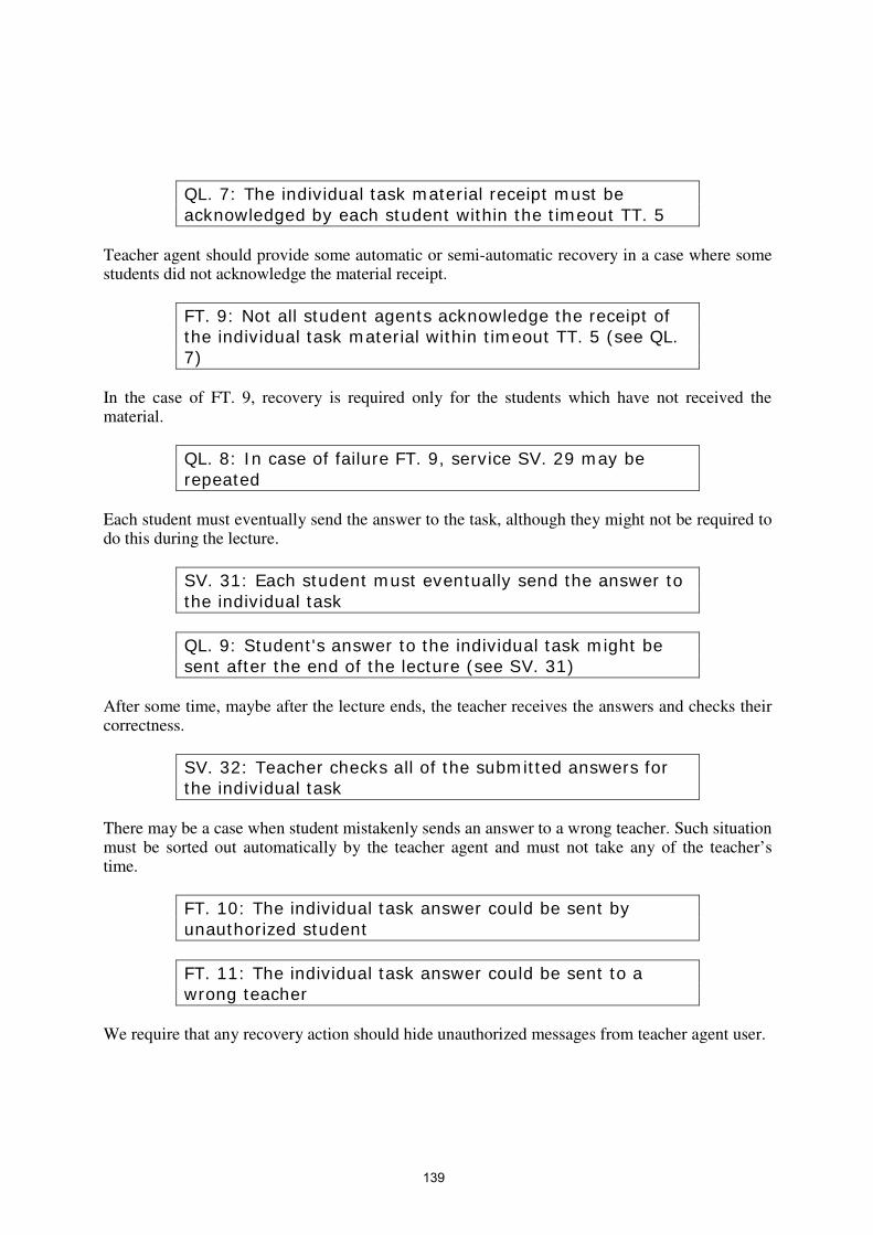
QL. 7: The individual task material receipt must be acknowledged by each student within the timeout TT. 5
Teacher agent should provide some automatic or semi-automatic recovery in a case where some students did not acknowledge the material receipt.
FT. 9: Not all student agents acknowledge the receipt of the individual task material within timeout TT. 5 (see QL. 7)
In the case of FT. 9, recovery is required only for the students which have not received the material.
QL. 8: In case of failure FT. 9, service SV. 29 may be repeated
Each student must eventually send the answer to the task, although they might not be required to do this during the lecture.
SV. 31: Each student must eventually send the answer to the individual task
QL. 9: Student's answer to the individual task might be sent after the end of the lecture (see SV. 31)
After some time, maybe after the lecture ends, the teacher receives the answers and checks their correctness.
SV. 32: Teacher checks all of the submitted answers for the individual task
There may be a case when student mistakenly sends an answer to a wrong teacher. Such situation must be sorted out automatically by the teacher agent and must not take any of the teacher’s time.
FT. 10: The individual task answer could be sent by unauthorized student
FT. 11: The individual task answer could be sent to a wrong teacher
We require that any recovery action should hide unauthorized messages from teacher agent user.
139
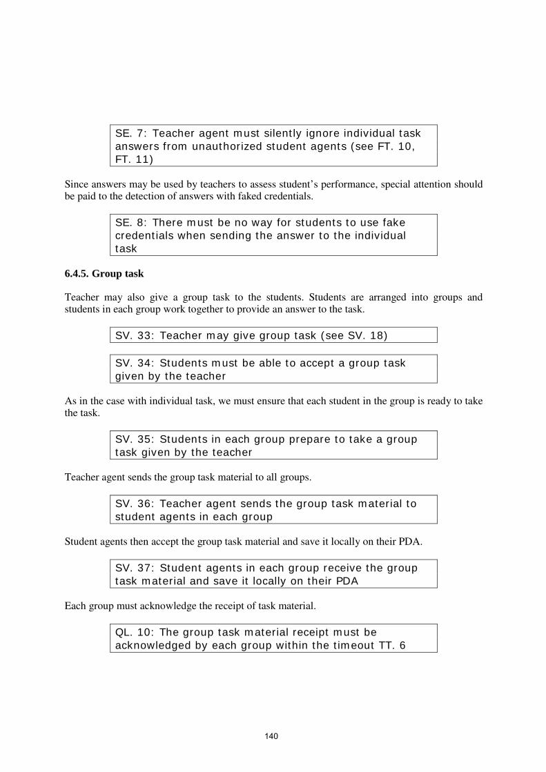
SE. 7: Teacher agent must silently ignore individual task answers from unauthorized student agents (see FT. 10, FT. 11)
Since answers may be used by teachers to assess student’s performance, special attention should be paid to the detection of answers with faked credentials.
SE. 8: There must be no way for students to use fake credentials when sending the answer to the individual task
6.4.5. Group task Teacher may also give a group task to the students. Students are arranged into groups and students in each group work together to provide an answer to the task.
SV. 33: Teacher may give group task (see SV. 18)
SV. 34: Students must be able to accept a group task given by the teacher
As in the case with individual task, we must ensure that each student in the group is ready to take the task.
SV. 35: Students in each group prepare to take a group task given by the teacher
Teacher agent sends the group task material to all groups.
SV. 36: Teacher agent sends the group task material to student agents in each group
Student agents then accept the group task material and save it locally on their PDA.
SV. 37: Student agents in each group receive the group task material and save it locally on their PDA
Each group must acknowledge the receipt of task material.
QL. 10: The group task material receipt must be acknowledged by each group within the timeout TT. 6
140

Teacher agent must handle the situation when one or more groups do not send an acknowledgement.
FT. 12: Not all the groups acknowledge the receipt of the group task material within timeout TT. 6 (see QL. 10)
In the case of FT. 12 failure, the teacher might decide to resend the group task material to some or all of the groups.
QL. 11: In case of failure FT. 10, service SV. 36 may be repeated
Each group must present the group answer to the teacher sometime during the lecture.
QL. 12: The answer or indication of inability to answer the group task must be received by the teacher before the lecture ends
Teacher collects the answers from all the groups and checks their correctness.
SV. 38: Teacher checks all of the submitted answers for the group task
It is possible that a group sends several answers for the same task. Teacher agent must detect such situation and resolve this automatically or assist the teacher on this matter.
FT. 13: There may be more than one answer submitted by a group
Just like in the case with individual tasks, correct credential for the group answers is an important security issue.
SE. 9: There must be no way for groups to use fake group credentials when sending the answer to the group task
6.4.6. Questions from students There is one kind of activity that is initiated by the students. Students, through their agents, may ask questions to the teacher any time during the lecture (even during an individual or a group task). This is the main communication channel from students to the teacher.
141

SV. 39: Students may directly ask questions to the teacher through their agents
Teacher agent must immediately detect any questions from students.
SV. 40: Teacher agent must be able to detect questions raised by the students
Teacher may answer immediately or later during the lecture or after the lecture or never at all. The answer may be private or public and can be given through ACE tools or in natural language or both.
SV. 41: Teacher may answer the questions raised by the students
SV. 42: Teacher's answer could be delivered through ACE or by traditional means (orally)
Questions may arrive simultaneously from several students, so teacher agent should sort and store these questions to be viewed and answered later by the teacher.
QL. 13: Teacher agent should be capable of handling multiple questions at the same time
Teacher agent must ignore any questions originating from students not participating in the current lecture.
SE. 10: Questions from students not participating in the lecture must be ignored by the teacher agent
6.4.7. Lecture ending Lecture ends when certain conditions are broken. If most of the students or the teacher has left the lecture then we assume that there is no need to provide agent-level support for lecture activity.
SV. 43: Lecture ends when there are less than N students or there is no teacher in the location
When lecture ends, all users might still stay in the same location but without any joint activity. They can either migrate to other location or organize a new lecture in the same location.
142

ST. 7: When a lecture ends or a user leaves the lecture location, the user's agent’s state is changed to free (see ST. 18)
ST. 7 above mentions “free” state. The meaning of this state is described in section 6.5.1. 6.5. Other states Lecture state is the largest part of the scenario. To simplify its description we decided to focus only on the lecture part and present a simplified view on the scenario for the readers. However it is impossible to build a complete system with an obscure and undefined “not-in-lecture” state. Not-in-lecture is an abstract state solely used to enable transition to/from the lecture part of the scenario from/to the rest. As shown in the Figure 6.3 below, not-in-lecture state corresponds to two states: free and migration.
Figure 6.3: New look at state transition between lectures “Free” state is an intermediate state which is used to give agents a choice of whether to participate in a lecture or migrate somewhere else or stay in the current location. An agent can stay in a free state for as long as it wants. “Migration” state is a situation where an agent is in the process of moving from one location to another. It was introduced to explicitly deal with physical migration problems present in mobile software. Migration process takes some time, during which many events and failures may occur and we want to explicitly introduce migration state, as connectivity-related failures are important to us. There are two other top level states: outside and emergency (see ST. 1) “Outside” state represents the state of those agents currently not participating in the scenario but
Lecture Not-In-Lecture Lecture
Lecture Free Lecture Migration Free
Outside
Full version
Simplified version
143

can join the scenario. Agents also leave the scenario by changing their state to outside. “Emergency” state is used to coordinately handle local or global emergency situations, such as fire alarm or electricity loss. This state is somewhat a special case here, where it is used to coordinate agents and users during recovery actions that require location-wide or even global recovery actions. There may be a transition to this state from any other states except outside state. The full diagram of the states present in the scenario is shown on the Figure 6.4.
Figure 6.4: Full diagram of the scenario states Failures may lead to transition to emergency state from lecture, free and migration states. For the sub-states of lecture state we require the nested activities to be finished prior to transition to emergency state. Effectively it is means usage of state-specific recovery procedures for the sub-states. States are also classified by the quality of ACE support. To simplify the scenario we do not deal we disconnection and other connectivity problems in free and lecture states. The focus on that is made in migration state, where we expect agents to experience repeated disconnections. Agents in outside state are not part of the scenario and even if they in a hotspot coverage area, there is no ACE support for them. 6.5.1. Free State A user’s agent is in a “free” state when the user is located in an ACE supported location but is not participating in a lecture. Under normal circumstances, a user’s agent that is currently in a “free” state can only change its state to either migration or lecture.
Lecture
Free Migration Outside
Group w. Test
Full Intermittent None ACE Support:
Emergency
144

ST. 8: User’s agent in free activity state can migrate to a different location
ST. 9: User’s agent in free activity state can register in a lecture happening in the location where the user is currently located
When global emergency state is activated, the state of every user’s agent in a given location must also be changed to emergency state.
ST. 10: User’s agent’s free activity state is changed to emergency state when emergency state is globally activated
6.5.2. Migration State Migration state captures details of the physical migration of the users, and along with that, the migration of the users’ agents in term of the connectivity area. This stage may include network disconnections and partial or total loss of ACE support.
FT. 14: Migration activity must tolerate wireless network disconnection and loss of ACE support
Network connection must be automatically reestablished when an agent enters into area covered by a wireless hotspot.
QL. 14: Agent must reestablish the network connection as soon as it enters wireless hotspot connectivity area
Agent must be able to continue its operation despite some operations may be interrupted by disconnection.
FT. 15: Any operations in migration stage must be able to tolerate permanent and temporary disconnections
When an agent enters an area of another hotspot or reestablishes connectivity with the original location, the agent’s state is changed to the “free” state.
ST. 11: Migration state changes to free state when the migrating agent appears in one of the scenario locations
145

An agent in migration state can change its state to outside at any moment, independent of the ACE or connectivity state. When agent changes its state to outside, it effectively leaves the scenario.
ST. 12: Agents currently in migration state may change their state to outside
If a global emergency is activated, all currently migrating agents must be switched into emergency state. However it is impossible to do it if there is no ACE support. In this case, emergency state for the agent is triggered later when the user with this agent comes to an area with ACE support. If ACE support is reestablished after the emergency situation is resolved then no emergency state transition is required for the particular agent.
ST. 13: Agents in migration state and with active ACE support will change their state to emergency when a global emergency is activated
6.5.3. Outside State Outside state is a way to represent the state of those agents whose users are currently not participating in the scenario. We are not concerned with their particular sub-states or activities and do not provide any services to them.
ST. 14: New agents appear and disappear in the scenario by changing their state from/to outside state
We are not concerned with the problem of how new agents are selected and when they should appear. This is left to the agents’ users and not specified in the scenario. 6.5.4. Emergency State and Failures In defining the fault tolerance requirements, we rely on the general framework for dependability engineering from [6.1]. This framework defines the process of development of these requirements in terms of identifying the fault assumptions, i.e. the events that might have unacceptable consequences on the system and its environment if not tolerated. In the Ambient Campus case study, these events come from both the system itself and its environment. Where appropriate, we augment the description of the failure assumption with the description of the required degraded operation mode. 6.5.4.1. ACE Support Due to the possibility of failures in ACE during a lecture, there may be cases where ACE support for some or all of the students or for the teacher is not available. We consider this as if the student or the teacher leaves the lecture. In the case where a considerable number of students
146

leave or if the teacher leaves, ACE support for the rest of the participants is stopped. However, the lecture may continue in the traditional way. We assume that only one fault can happen at a time. 6.5.4.2. Failures There could be cases where one or more student experiences PDA failure or their ACE support is temporary halted. There should be some recovery procedure to allow PDAs to be quickly configured so that they are ready to be used in ACE.
FT. 16: Student’s PDA may fail on some operations If recovery for the student agent participating in the lecture activity succeeds then ACE support for that agent will be restored.
QL. 15: Student’s agent should recover, if possible, from a PDA failure during the lecture (see FT. 16)
QL. 16: Upon successful recovery, ACE support for the failed PDA can be restored (see FT. 16, QL. 15)
Students with a completely failed PDA should try to continue following the lecture without ACE support. In some cases, this event may drop ACE support for the whole lecture.
FT. 17: Student’s PDA may completely stop working Note that in some cases, FT. 16 and FT. 17 may result in the whole ACE support for the lecture to be stopped (see requirement SV. 43). Fire alarm can be toggled automatically in all the locations of the scenario. We assume that ACE support can be operational for long enough to be used to help the students and the teacher to leave the building.
FT. 18: Fire alarm may be activated in all the scenario locations at the same time
In the case of such an event, all users within the scenario must leave the building. Recovery action for fire alarms attempts to change the state of all the agents in the scenario to emergency. Note that for lecture sub-states we do not allow direct transition to any emergency state, thus lecture sub-states are first aborted (with their own recovery procedure) and only then the agents are put into emergency state.
147

ST. 15: In the case of fire alarm, state of all the agents is changed to emergency (see FT. 18)
This state transition is referred-to in this section as a global emergency event. PDAs should be used to guide users to the nearest fire exits. Since we do not expect the use of GPS or any other kind of navigation system, guidance provided is basically a map that shows nearest fire exits, based on the user’s current location.
QL. 17: In case of fire, PDAs should guide users to the nearest fire exits (see FT. 18)
If fire alarm is de-activated, users can return to their interrupted activities. This means that they will return to the state from which the transition to emergency state was made.
ST. 16: If fire alarm is de-activated, the emergency state is changed to the most recent interrupted state (see FT. 18)
In the case of electricity failure, there is no wireless network. However PDAs with their independent power source may continue to operate.
FT. 19: Electricity failure may affect any location Individual PDAs must backup their state so that the interrupted activity can be resumed later.
QL. 18: In case of electricity failure in the location, student agents must backup their state (see FT. 19)
When there is no wireless network there is effectively no location defined. This means that the agents must switch to migration state and either look for other locations in the scenario or leave the scenario altogether.
ST. 17: In case of electricity failure in the location, agents switch to migration state
If most of the agents, including the teacher agent, recovered then the lecture can be continued with ACE support.
QL. 19: If a minimal required number of students have recovered from FT. 19 then ACE support for the lecture can be reestablished
148

Generally this failure cannot be handled automatically by the agents and some assistance from the users is required. 6.6. Summary of the states Now we can outline possible state transitions in the scenario. Only major states are included and transition for the lecture sub-states are discusses in lecture state section.
ST. 18: The following top-level states transitions are allowed: lecture free migration outside emergency
lecture ST. 7 ST. 17 ST. 15
free ST. 9 ST. 8 ST. 10, ST. 15
migration ST. 11 ST. 14 ST. 13, ST. 15
outside ST. 14
emergency ST. 16
Requirement names given in the boxes provide additional explanation on the particular state change. The first column is for the initial states and the rows are for the destination. Blank boxes correspond to prohibited state changes or those state changes that are beyond our interest. Referenced requirements provide additional explanations of the transition.
6.7. Dynamicity and reconfigurability To capture some dynamic aspects, the case study is modelled as an open system where the number of students and teachers can change dynamically. This is possible when each agent is somehow compatible with other agents. Agents in outside state do not have an ACE support, cannot participate in any activities and cannot be addressed by the members of the scenario.
EN. 22: ACE is disabled for agents in outside state However, when an agent changes its state from outside to migration and appears in one of the scenario locations this is considered as appearance of a new participant in the scenario. Agents can temporary leave the scenario and later return back (see ST. 14). Any agent that implements the functionality required by the scenario can join the scenario as a new participant. Also there must be a way to inspect agent capabilities to ensure that the agent/user pair can take part in the scenario and with the properly assigned role.
EN. 23: All agents in outside state have required functionality to participate in the scenario
For any agent with currently active ACE support it is possible to identify its physical location. It
149

is assumed that a user is always in the same location as his/her agent.
EN. 24: Location is known for any agent with currently active ACE support
When a user is migrating and is not connected to any hotspot, we cannot associate them with any of the locations.
ST. 19: User location is undefined during the migration stage when there is no ACE support
We cannot determine the routes for migrating users and they can finally show up in any location or leave the scenario. This is not a restriction since migration corresponds to users walking with their PDAs across campus and we cannot control their behavior.
EN. 25: Users migration behaviour is non-detereministic All locations have the same functionality. For simplicity we assume that any location can support any lecture type and users have no preference for any particular location.
EN. 26: All the locations have the same functionality However the number of locations is not fixed. We might introduce new locations in the scenario.
EN. 27: New locations might be added to the scenario Certain locations may be removed from the scenario, for example we might decide to drop ACE support in a particular lecture room.
EN. 28: Existing locations might be removed from the scenario
6.8. Timeouts This is the list of timeouts used in the scenario, they are all part of lecture state description. See the referenced requirements for further explanations of the timeouts.
TT. 1: Lecture registration timeout, counting from SV. 2 (see QL. 1)
TT. 2: Lecture key distribution timeout, counting from SV. 7 (see QL. 2)
150

TT. 3: Lecture material distribution timeout, counting from SV. 15 (see QL. 3)
TT. 4: Group name organisation timeout, counting from notification SV. 21 (see QL. 5)
TT. 5: Individual task distribution timeout, counting from SV. 29 (see QL. 7)
TT. 6: Group task distribution timeout, counting from SV. 36 (see QL. 10)
6.9. Acknowledgements We would like to thank Jean-Raymond Abrial and Stéphane Lo Presti for their feedback. 6.10. References [6.1] M. Kaaniche, J.-C. Laprie, J.-P. Blanquart. A framework for dependable engineering of
critical systems. Safety Science 40, pp. 731-752, 2002
151