rod r&d status k. johns, c. armijo, j. steinberg (u. arizona) h. chen, f. lanni, j. mead (bnl)...
TRANSCRIPT

ROD R&D Status
K. Johns, C. Armijo, J. Steinberg (U. Arizona)H. Chen, F. Lanni, J. Mead (BNL)
L. Hervas (CERN) A. Meyer, A. Kielburg-Jeka, A. Straessner (Dresden)G. Perrot, A. Bazan, F. Bellachia, I. Wingerter-Seez
(LAPP)M. Citterio (INFN, Milano)
D. Schamberger (SUNY, Stony Brook)

Optical Link NotesCurrently we build with
Reflex Photonics SNAP12 Emcore SNAP12
Both specified @ 3.3 Gbps
Recent news/results Delivery date for Reflex Photonics SNAP12
@ 6.25 Gbps still +6 weeks First promised for July 1
Both RP and Emcore 3.3 Gbps versions can run at higher speeds Emcore shows better performance (up to 5
Gbps) based on measured BER
2
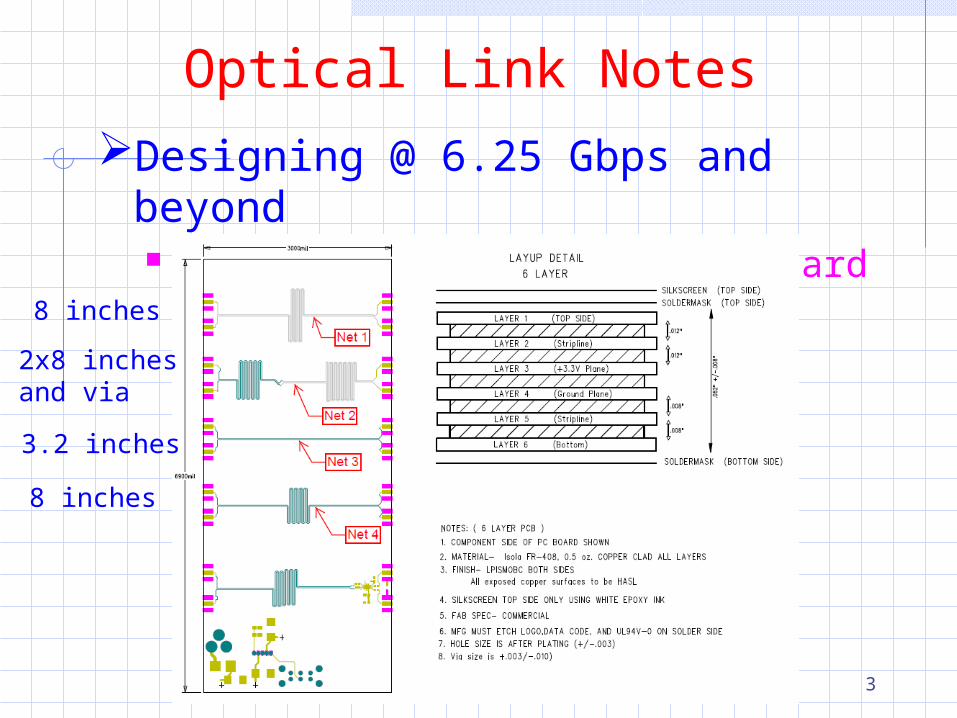
Optical Link Notes
Designing @ 6.25 Gbps and beyond Measurements with AZ test board
3
8 inches
8 inches
2x8 inchesand via
3.2 inches
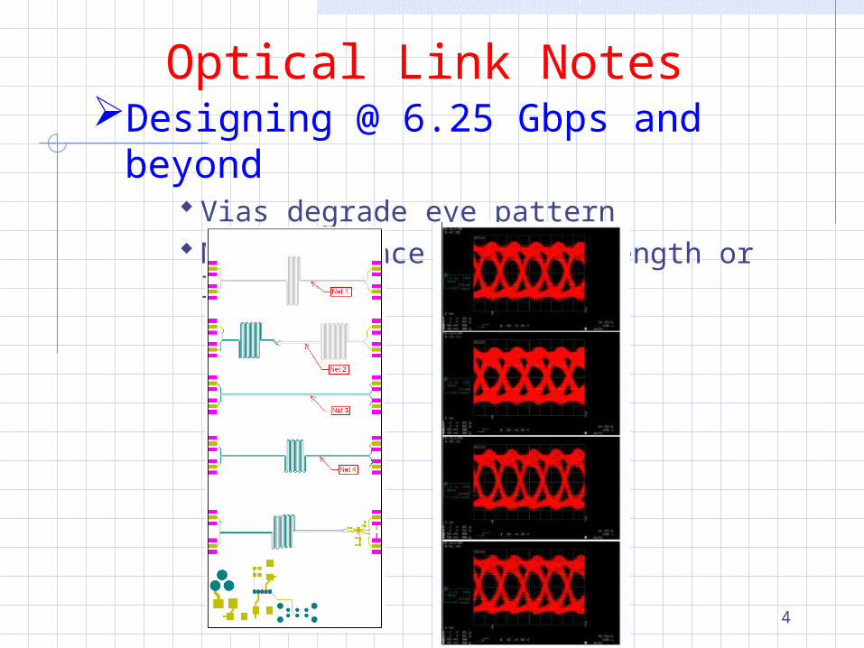
Optical Link NotesDesigning @ 6.25 Gbps and
beyond Vias degrade eye pattern No difference in trace length or layer
4
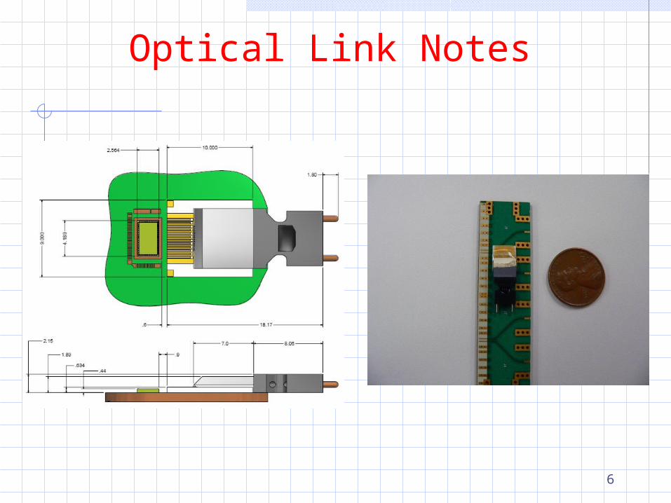
Optical Link NotesIn order to move to higher optical
density we are now designing with Reflex Photonics LightABLE OE OE is an IC with 12 channel GaAs VCSEL or
12 channel GaAs PIN photodetector Connected electrically via wire bonds Connected optically via MT connector
Present speed @ 6.25 Gbps Designer provides an electrical footprint
on the PCB RP mounts (wirebonds) the OSA
OE part and mounting cost is ~$350 / die
5
Optical Link Notes
6
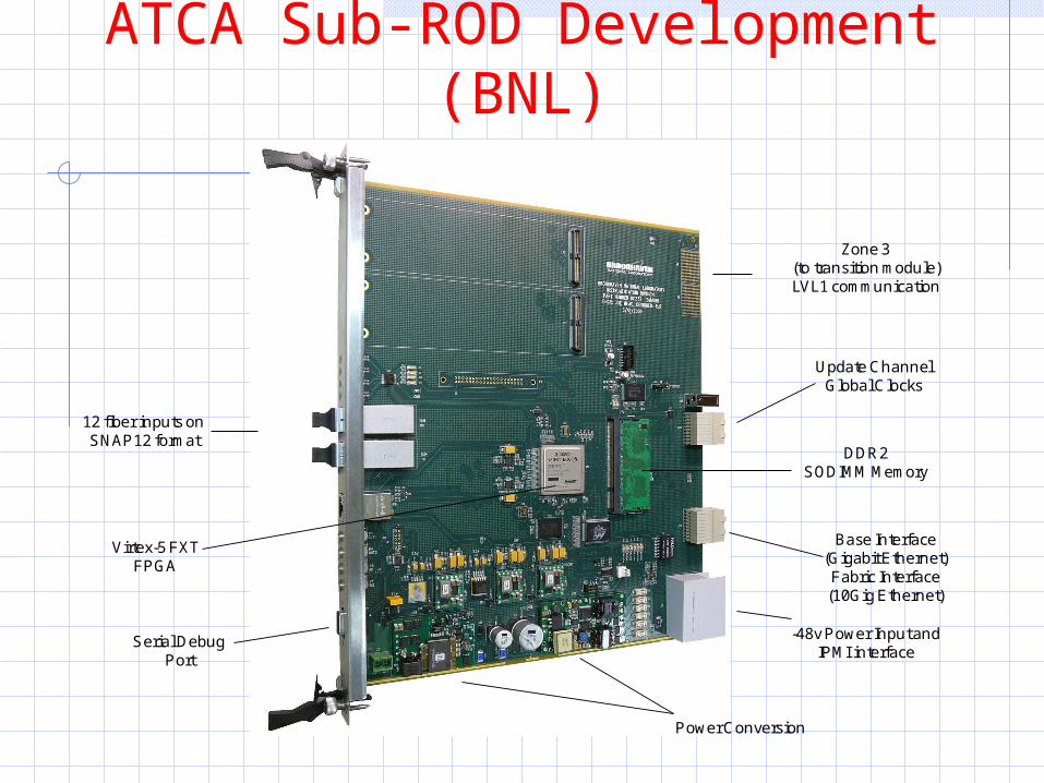
ATCA Sub-ROD Development (BNL)
Base Interface (Gigabit Ethernet)Fabric Interface (10Gig Ethernet)
Zone 3 (to transition module) LVL1 communication
Update ChannelGlobal Clocks
-48v Power Input and IPMI interface
12 fiber inputs on SNAP12 format
DDR2SODIMM Memory
Virtex-5 FXT FPGA
Power Conversion
Serial Debug Port

ATCA Sub-ROD Development AdvancedTCA 8U Module
With separated +5V power connector and Gigabit Ethernet connector on front panel, it allows testing of main functions without ATCA crate
IPMI development is underway, using development document and source code from DESY. Even though we use different processor, all the code is in C which helps software porting
One sub-ROD module was shipped to Dresden in late June/early July
High Speed Parallel Optical Links and FPGA SERDES Self loopback test works at 3.2Gbps on 12 channels, 40Gbps
total bandwidth Sub-ROD (and sub-ROD injector) still awaiting 75 Gbps
transceivers from Reflex Photonics Present plan is to do another round of sub-ROD and sub-
ROD injector integration tests in October using Emcore parts which can run over spec (~5 Gbps)

ATCA Sub-ROD Injector (AZ)
Sub-rod injector ATCA card also now available
9
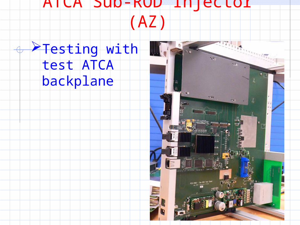
ATCA Sub-ROD Injector (AZ)
Testing with test ATCA backplane
10
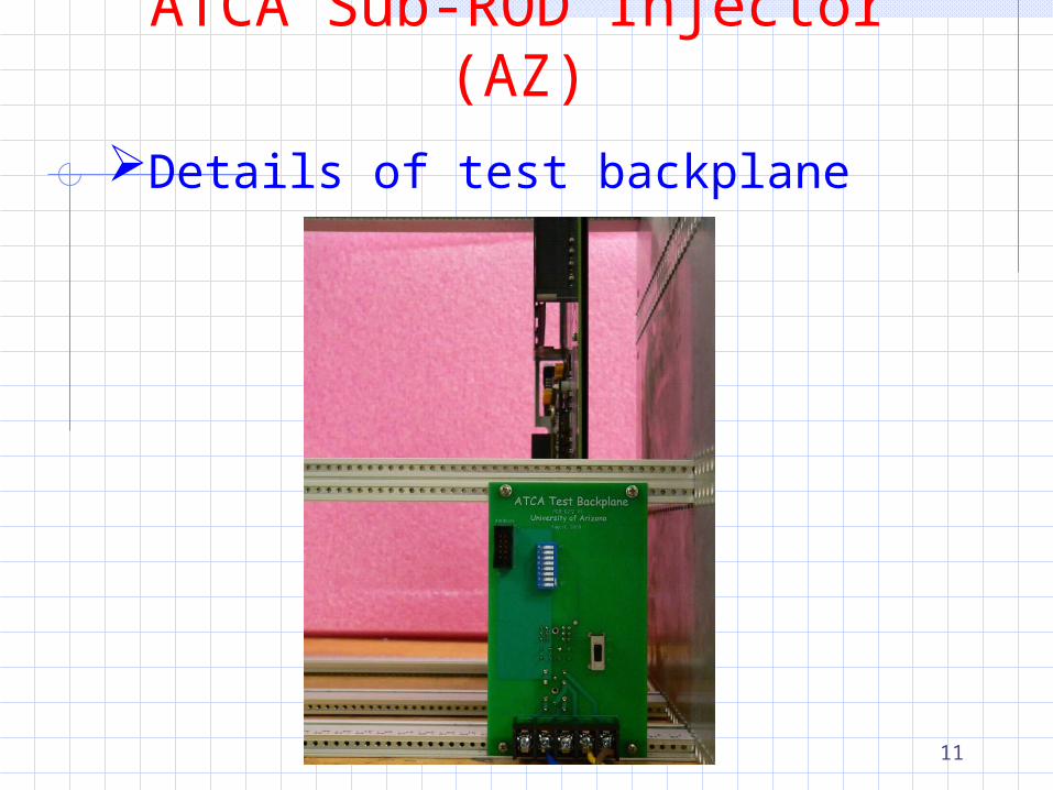
ATCA Sub-ROD Injector (AZ)
Details of test backplane
11
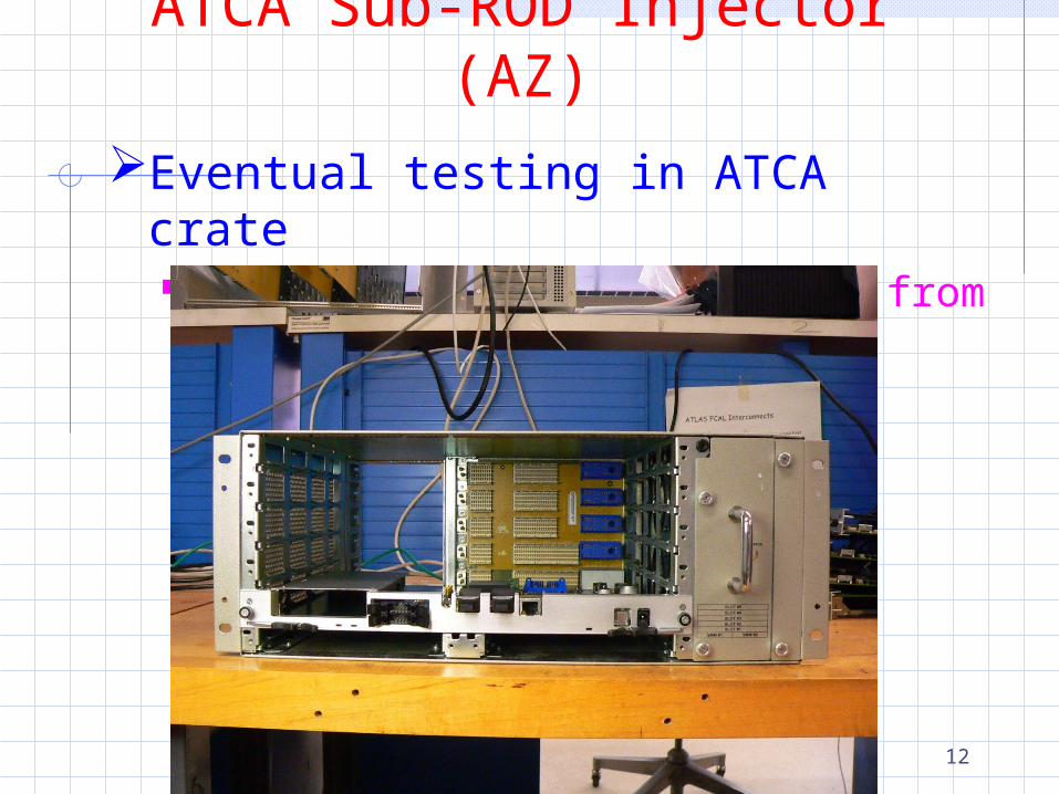
ATCA Sub-ROD Injector (AZ)
Eventual testing in ATCA crate We received this demo model from
ASIS
12
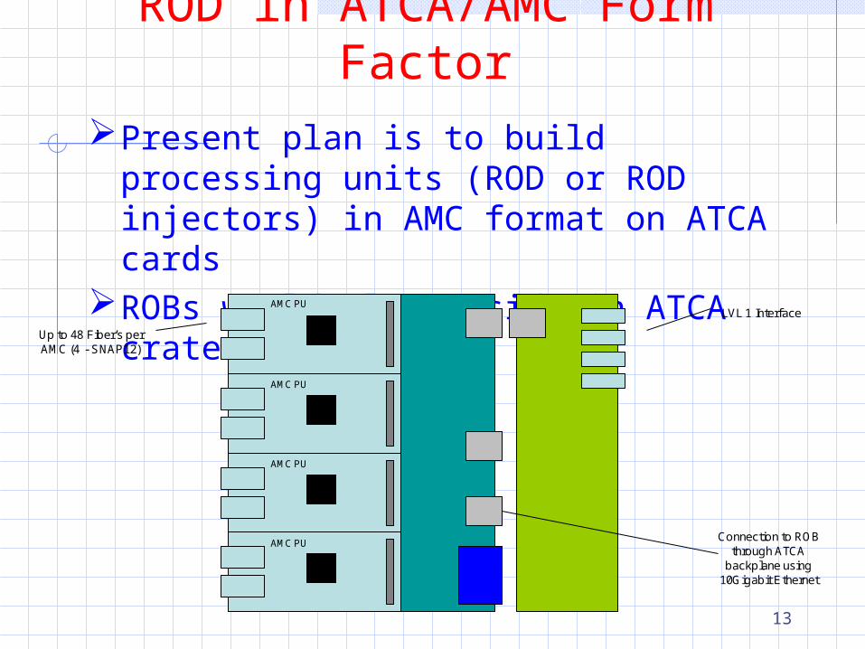
ROD in ATCA/AMC Form Factor
Present plan is to build processing units (ROD or ROD injectors) in AMC format on ATCA cards
ROBs would also reside in ATCA crate
13
Up to 48 Fiber’s per AMC (4 - SNAP12)
LVL 1 Interface
Connection to ROB through ATCA
backplane using 10Gigabit Ethernet
AMC PU
AMC PU
AMC PU
AMC PU
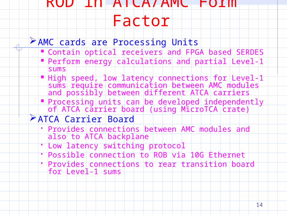
ROD in ATCA/AMC Form Factor
AMC cards are Processing Units Contain optical receivers and FPGA based SERDES Perform energy calculations and partial Level-1 sums High speed, low latency connections for Level-1 sums
require communication between AMC modules and possibly between different ATCA carriers
Processing units can be developed independently of ATCA carrier board (using MicroTCA crate)
ATCA Carrier Board Provides connections between AMC modules and also
to ATCA backplane Low latency switching protocol Possible connection to ROB via 10G Ethernet Provides connections to rear transition board for Level-
1 sums14

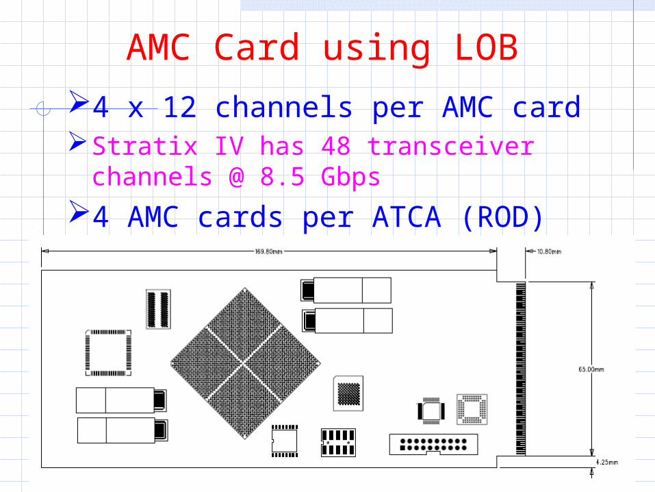
AMC Card using LOB
15
4 x 12 channels per AMC card Stratix IV has 48 transceiver channels
@ 8.5 Gbps
4 AMC cards per ATCA (ROD)
EPROM
DDR3
Flash Ethernet
PCI Express Driver
Microcontroller
AMC Card using LOB
16
4 x 12 channels per AMC cardStratix IV has 48 transceiver channels @
8.5 Gbps
4 AMC cards per ATCA (ROD)

AMC Sub-ROD Two ATCA boards per half barrel FEC
2 SNAP12 connectors / AMC card x 1 FEB/SNAP12 x 4 AMC cards = 8 FEBs
Assumes 10 Gbps transmission
One ATCA board per half barrel FEC 4 optical connectors / AMC card x 1
FEB / SNAP12 x 4 AMC cards = 16 FEBs
This eliminates data transmission between different ATCA boards eases processing of the Level-1 trigger sum
The MTP connectors utilize the same MT ferrules and package them in a push-pull keyed connector housing for quick and easy connection
The width of MTP connector is ~15mm, which is more than twice of the width of MT connector
Molex high density optical MT connectors
Circular MT: single MT ferrule, 12 to 72 fibers per ferrule
1x6 Array: 6 MT ferrules, 12 fibers per ferrule
Both Molex and Tyco offer high density optical MT cable assemblies using 72-fiber MT ferrule in the industry standard MTP connector
MTP Connector
Disassembly of MTP Connector
MT Connector
sLHC LAr ROD Upgrade R&DMailing list
[email protected] espace
https://espace.cern.ch/slhc-atlas-lar-rodPhone meeting
First meeting was organized on Sept. 11th; people from Univ. of Arizona, BNL, Dresden, LAPP and Stony Brook Univ. were connected
Goal was to update what everybody’s been working on and discuss how to proceed
Plan to continue this phone meeting once a month