rock mechanics research at the lucky friday mine
TRANSCRIPT

T E C H N I C A LE N V I R O N M E N T A LS A F E T YH E A L T H
Rock Mechanics Research at the Lucky Friday Mine
CIM, May, 2015

H E C L A M I N I N G C O M P A N Y
Objective
Describe the rock mechanics challenges of deep mining at Hecla’s Lucky Friday Mine
Discuss the seismicity and ground control mitigation strategies employed at the mine, particularly the stress shadowing approach for pillar destressing and deformable ground support for control of large deformations
Provide a progress report on implementation of these strategies since the mine was re-opened in 2013
2
H E C L A M I N I N G C O M P A N Y
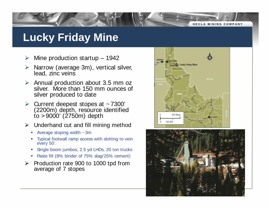
Lucky Friday Mine Mine production startup – 1942 Narrow (average 3m), vertical silver,
lead, zinc veins Annual production about 3.5 mm oz
silver. More than 150 mm ounces of silver produced to date
Current deepest stopes at ~7300’ (2200m) depth, resource identified to >9000’ (2750m) depth
Underhand cut and fill mining method Average stoping width ~3m Typical footwall ramp access with slotting to vein
every 50’. Single boom jumbos, 2.5 yd LHDs, 20 ton trucks Paste fill (8% binder of 75% slag/25% cement)
Production rate 900 to 1000 tpd from average of 7 stopes

H E C L A M I N I N G C O M P A N Y
Mine Layout
Primary vein is 30 Vein with 5 stopes. 2 to 3 additional stopes on parallel footwall veins. All vertical dip.
Average strike length of orebody is 2500’ to 3000’ (750 to 900m)
Two primary underhand mining fronts, one down from 5500 level, one down from 5900 level
Sill pillar created below 5500 mining front
4
Underhand mining front 1
Underhand mining front 2
Sill Pillar
#4 Shaft
~6200 Level, 2200m depth
~5500 Level, 1980m depth
H E C L A M I N I N G C O M P A N Y
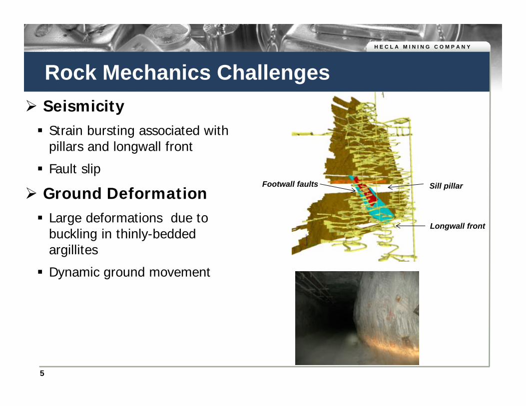
Rock Mechanics Challenges Seismicity Strain bursting associated with
pillars and longwall front
Fault slip
Ground Deformation Large deformations due to
buckling in thinly-bedded argillites
Dynamic ground movement
5
Sill pillarFootwall faults
Longwall front
Sill pillar

H E C L A M I N I N G C O M P A N Y
Seismic Events, 2007 to present
6
Events in advance of longwall
Events associated with pillar and fault slip
Moment Magnitude

H E C L A M I N I N G C O M P A N Y
Seismicity Mitigation Strategy
7
Assess Seismic Sources
• Numerical Modeling of Stresses and Fault-Slip Potential
Mining Strategy
• Stress Shadowing of Pillars and Faults by Mining Parallel Veins• Re-entry protocols after stope blasting
Instrument and Adjust Mining as
Needed
• Seismic Monitoring• Stress Change in Pillar and Fault Displacement Measurement• Stope Closure and Fill Pressure Measurement• 3D Photogrammetry
Dynamic Ground Support
• D-Bolts• Deformable mesh

H E C L A M I N I N G C O M P A N Y
Stress-Shadowing Concept Gold Hunter vein
“package” consists of multiple, parallel veins
Advanced mining on one vein will divert stresses from adjacent veins/pillars
Parallel vein should be far enough from pillar to minimize stress interaction of stope faces
8
Stress concentration in
sill pillar
Stress diverted from sill by mining on
parallel vein

H E C L A M I N I N G C O M P A N Y
Numerical Modeling of Stress Shadowing –Gold Hunter Sill Pillar
Current State –Sill Pillar Below
Underhand Stope on 30 Vein
Mining on Shadow Stope by CF Until Interaction of
Stopes
Final Extraction with LH Blast
Complete Destressing
of PillarSill Pillar
30 Vein Stress Shadow Stope

H E C L A M I N I N G C O M P A N Y
Instrumentation for Monitoring Shadow Stope
10
Seismic
3D Photogrammetry for Fault Kinematics
Biaxial Stress Change
Fault Movement Stope Closure and Paste Fill Stress
H E C L A M I N I N G C O M P A N Y
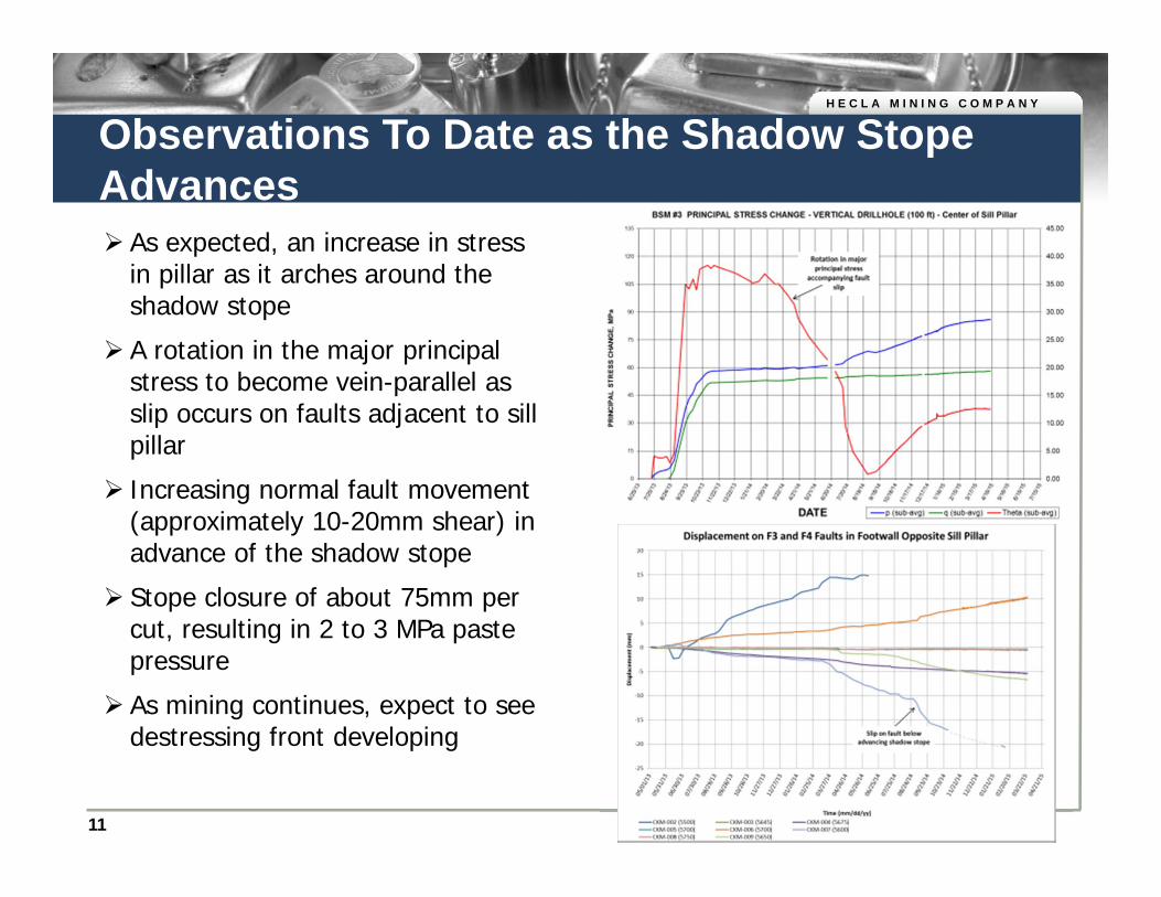
Observations To Date as the Shadow Stope Advances As expected, an increase in stress
in pillar as it arches around the shadow stope
A rotation in the major principal stress to become vein-parallel as slip occurs on faults adjacent to sill pillar
Increasing normal fault movement (approximately 10-20mm shear) in advance of the shadow stope
Stope closure of about 75mm per cut, resulting in 2 to 3 MPa paste pressure
As mining continues, expect to see destressing front developing
11

H E C L A M I N I N G C O M P A N Y
Ground Support Testing Current dynamic support method D-Bolt high deformation grouted smooth
bars on 4’x4’ spacing
Chain link (50mm opening)
100mm shotcrete
Large deformation testing and energy dissipation of support system Large-panel support system quasi-static
load testing at NIOSH laboratory, Spokane, Washington
Support system shows elastic-plastic response with constant load capacity to over 25cm deformation
Testing indicates significant load capacity increase when using fiber in addition to mesh-reinforcement
Field experience has shown positive results using D-Bolt and chain link support under seismic loading
12

H E C L A M I N I N G C O M P A N Y
Results of D-Bolt/Shotcrete/Chain Link Panel Testing
13
Note: Test results primarily show energy dissipation of the shotcrete/chain link as D-Bolts not failed.

H E C L A M I N I N G C O M P A N Y
Containment of Stope Sidewall Displaced by Seismic Event
D-Bolts and chain link
Approximately 1’-2’ of inward sidewall movement contained by support
Example of stretched and broken D-Bolt
14

H E C L A M I N I N G C O M P A N Y
Summary
Lucky Friday mine strategy for dealing with ground control issues includes: Proactive stress shadow mining to strategically destress pillars created
by multiple mining fronts
Use of deformable support elements with high energy dissipation capacity for dynamic and squeezing ground conditions
Numerical prediction and rock mass instrumentation to provide feedback for modification of design
On-going project, results thus far as expected
15

H E C L A M I N I N G C O M P A N Y
Questions?
Thank You!