robust turbo analog error correcting codes based on analog ...€¦ · of the cyclic redundancy...
TRANSCRIPT

1
Robust Turbo Analog Error Correcting Codes Basedon Analog CRC Verification
Avi Zanko∗,, Amir Leshem∗ (Senior Member, IEEE), Ephraim Zehavi∗(Fellow, IEEE)
Abstract— In this paper, a new analog error correcting codewith an iterative decoder is presented for real-valued signalscorrupted by impulsive noises. In the proposed algorithm, aredundancy coding matrix is implemented as an analog versionof the cyclic redundancy check (CRC) that is commonly usedfor data verification in digital communication. On the basis ofthis analog CRC, we propose an alternate decoding scheme withiterative decoding. In each iteration of the algorithm, the problemof decoding the long block code is decoupled into a set of parallelLP/LASSO subproblems. In the sparse noise model, this leadsto a significant reduction in decoding complexity as comparedto one-step convex programming decoding. The new code hasimproved correction capability compared to Zanko et al. [3]. Inthe almost sparse noise model, energy detectors are used to verifythe decoding correctness of the inner code before transferring theresult to the next iteration. In this case, the Turbo decoder showslittle loss compared to the oracle bound based on least squareswhen the impulsive noises are perfectly known at the receiver.
Index Terms—Analog codes, Compressed Sensing, LASSO,Turbo decoding, CFAR.
I. INTRODUCTION
Analog error correcting codes were first proposed in [4, 5]to correct impulsive noises. Unlike digital codes in which alloperations are done over a finite field (also known as the Galoisfield), in analog coding schemes, both the encoding and de-coding schemes are done over the real (or complex) numbers;hence the codes can be implemented with operations that arenormally available in standard digital signal processors. Forinstance, there is an analogy between error correction codesand filter banks [4]. Analog codes can reduce computationalcomplexity compared to fully digital approaches and in somecases analog codes are preferable since digital approaches aresuboptimal for example when the source-channel separationdoes not apply (see e.g., [6] in which a joint source-channelcode is presented using tools from chaotic dynamical systems).
A. Applications
There are many applications of analog coding. Gabay etal. [7–9] showed that a real Bose-Chaudhuri-Hocquenghem(BCH) code can be used for simultaneous source coding andimpulse noise cancellation robust image transmission overrealistic satellite channels. In the context of discrete Fourier
Copyright (c) 2015 IEEE. Personal use of this material is permitted.However, permission to use this material for any other purposes must beobtained from the IEEE by sending a request to [email protected].
∗ Faculty of Engineering, Bar-Ilan University, Ramat-Gan, 52900, Israel. Corresponding author, email: [email protected]. This paper is part of
a Ph.D. thesis at Bar-Ilan University. Part of the paper was presented in [1]and [2]. This research was partially supported by ISF grant No. 903/2013.
transform (DFT) codes, [10–12] addressed the issue of burstyerasures with DFT codes and it has been shown that forDFT codes, the reconstruction error increases exponentiallywith the number of consecutive erasures and the DFT codelength. Henkel [13] showed that using Wolf analog codes1
(also known as DFT codes, real BCH or Analog Reed Solomon(RS) codes) can reduce the high peak-to-average ratio (PAR)of multi-carrier modulation signals, and Abdelkefi et al. foundthat an analog coding scheme can be used to reduce thepeak to average power ratio (PARP) [14]. Wang and Gian-nakis [15] introduced complex field precoding for orthogonalfrequency-division multiplexing (CFC-OFDM). In [16] Henkeland Hu showed that OFDM can be seen as an analog RScode if a cyclically consecutive range of carriers is not usedfor transmission, and in [17–20] Abdelkefi et al. used thepilot tones of the OFDM system as a syndrome to correctimpulsive noise in the presence of additive white Gaussiannoise (AWGN). Recently, real-BCH codes were also used fordistributed lossy source coding over a digital (possibly low-delay) communication channel [21]. In this approach, the errorcorrection code is implemented in the real field before thequantization. Hence, the dependency between the continuous-valued sources can be taken into account in the correlationchannel model rather than the quantized sources, resultingin a more realistic model. As was mentioned earlier, thereis analogy between error correction codes and filter banks[4]. This analogy was later extended in [22] and adoptedfor purposes of e.g., precoding and equalization with/withoutconstraints on channel zero locations [23–25] and also forjoint source-channel coding in [8]. A different type of analogcode is known as space time coding (STC). A linear spacetime block code is used to generate transmit redundancy overthe real/complex field [26], [27–29]. In addition, analog STCinspired by the Alamouti code are used for Generalized OFDMtransmission [30, 31]. However, these codes were designedfor additive Gaussian noise (AGN) and cannot be used forimpulsive noise.
B. Related Works
In linear analog error correcting codes, the goal is toreconstruct an information vector m ∈ RK from a corruptedmeasurement vector y = Gm + e where G ∈ RN×K is afull column rank coding matrix and e is a certain noise vectorin RN . A large body of results in the literature focuses oneliminating impulsive noises assuming that e is a sparse vector
1The generator matrix of these codes was constructed by eliminating certaincolumns of the inverse discrete Fourier transform (IDFT) matrix.
2
e.g., [4, 5, 32–36]. Thorough this paper, we refer to this modelas the sparse noise model. Specifically, in the sparse noisemodel, it is assumed that e = e0, where e0 is an arbitrarysparse error vector where under certain conditions an exactreconstruction of m is possible. In the more general model,one can assume that e = e0 + z, i.e., the corrupting vector eis almost sparse and is the combination of impulsive noisesmodeled by an arbitrary sparse vector e0 and small errors zthat affect all the entries of the input vector y. Obviously, inthis noisy model there is no hope for exact reconstructionof m from y and the key question is how well one canrecover m from y. A common reconstruction criterion is theℓp/ℓq sparse approximation. An algorithm is said to meet theℓp/ℓq sparse approximation criterion if it can guarantee that∥e − e∥ℓp ≤ c1
t1−1/p ∥e − et∥q + c2∥z∥p, where et is theestimation of e obtained by taking the largest (in terms ofabsolute values) t entries of e0.
By introducing an (analog) parity check matrix [4] H ∈Rr×N , such that r = N − K and HG = 0 the syndromevector can be defined as s := Hy = He. In [37] it wasshown that there is a theoretical upper bound on the sparsityrequirement for the error vector for a given parity checkmatrix H. An equivalent upper bound was developed fora given coding matrix in [33]. This upper bound basicallysays that if the error vector has too many non-zero entries,it is impossible to decode m unambiguously (i.e., by anyalgorithm). We are looking for the sparsest error vector thatexplains the measurement vector y. Therefore, we want tosolve the problem
m = arg minx∈RK
∥y −Gx∥ℓ0 , (P0)
where for any vector v, ∥v∥ℓ0 := |i : vi = 0|. Notethat since G is a full column rank, reconstructing m from yand reconstructing e from y are equivalent problems. Hence,instead of solving (P0) one can solve
e = argminx
∥x∥ℓ0 subject to Hx = s (= He). (P0′)
Unfortunately, solving either (P0) or (P0′) in general is
NP-hard [38]. However, these problems have been extensivelystudied under several frameworks such as coding theory andcompressed sensing (CS). In the coding theory framework,the coding matrix constructions and the decoding algorithmsare designed to exploit the similarity between the Hammingweight and the ℓ0-(pseudo) norm. Techniques of decodingBCH codes have been utilized to decode real number codesas well as adapt them to reals (complex numbers), see e.g.[39] where the Peterson-Gorenstein-Zierler (PGZ) decoder wasused to decode the analog code of [5]. Compressed sensingis a method for efficiently acquiring and reconstructing ahigh dimensional signal. The method exploits the fact thatin many problems, the information that determines the highdimensional signal is usually sparse in a certain domain. Thecentral objective of compressed sensing is to take as fewlinear combinations of the data as possible using a sensingmatrix Φ. Specifically, we want to sample a t-sparse vectorx ∈ RN with only r ≪ N measurements using a samplingmatrix Φ ∈ Rr×N . This leads to a reconstruction formulation
that is equivalent to (P0′) with the replacement of the parity
check matrix H by the CS matrix Φ and e by x. In the CSframework, it has been shown [33, 40–42] that under certainconditions on H and the size of the support of e, there is anℓ0-ℓ1 equivalence and decoding is possible by solving
m = argminx
∥y −Gx∥ℓ1 (P1)
or,
e = argminx
∥x∥ℓ1 subject to Hx = s (= He) (P1’)
instead of (P0) and (P0′), respectively. Since both problems
can be recast as linear programming (LP) problems [33], werefer to these as the LP-decoder approach.
In the LP-decoder approach, the parity check matrix isusually designed to have a certain recoverability property thatguarantees the ℓ0-ℓ1 equivalence. Examples of these propertiesinclude the mutual incoherence property [41, 43, 44] and therestricted isometric property (RIP) [33]. The incoherence prop-erty with coherence coefficient µ means that for every pair ofcolumns of a parity check matrix we have that |⟨hi,hj⟩| ≤ µi = j, where ⟨a,b⟩ = aHb denotes the inner product betweena and b. The special case where the parity check matrixH is constructed by concatenating two unitary matrices wasconsidered in [41, 43, 44] and extended by Gribonval et al. [45]to the case of concatenating of L orthonormal matrices. It wasshown that the ℓ0-ℓ1 equivalence holds as long as ∥e∥ℓ0 < c· 1µ(where for each L, c is a constant). In [46], it was shownthat if H is an r × N parity check matrix with normalizedcolumns N ≥ 2r, then µ ≥ 1√
2r. Hence, if N ≥ 2r the
mutual incoherence property cannot guarantee correction ofmore than O(
√N) errors. The restricted isometry property
is another important property of parity check matrices (orCS matrices). The restricted isometry property characterizesmatrices that are nearly orthonormal only when they operateon sparse vectors. Let H be a parity check matrix; the RIP oforder L is defined as the smallest number δL such that for anyL-sparse vector x: (1−δL)∥x∥2ℓ2 ≤ ∥Hx∥2ℓ2 ≤ (1+δL)∥x∥2ℓ2 .The importance of this property lies in its ability to guaranteethe ℓ0-ℓ1 equivalence. It was shown in [47] that the ℓ0-ℓ1equivalence holds if δ2t <
√2 − 1 as long as ∥e∥ℓ0 ≤ t.
Note that unlike the mutual incoherence property, there isno low-complexity algorithm that verifies whether a generalmatrix satisfies the RIP or not. However, a large family ofrandom matrices (see e.g., [33, 48]) has RIP constants in whichthe LP-decoder is capable of correcting ρN errors with anoverwhelming probability.
There are several extensions for (P1’) to the almost sparsenoise model (i.e., when small errors corrupt all the entries ofthe input vector y in addition to the sparse impulsive noisee0). Examples of these algorithms include the least absoluteshrinkage and selection operator (LASSO) [49], basis pursuitdenoising (BPDN) [50] and the Dantzig selector (DS) [51].These algorithms are summarized in Table I. There are similarextensions for the LP-decoder (P1) to the almost sparse model.A good example is the LASSO-decoder [42]. Specifically,given a coding matrix with orthonormal columns, the LASSO-

3
decoder is defined as
minz∈RN ,x∈RK
∥y −Gx− z∥ℓ1 subject to ∥z∥ℓ2 ≤ ϵ
GT z = 0.(1)
Note that LASSO, BPDN and DS can be recast as second ordercone programming (SOCP), quadratic programming (QP) andLP, respectively. In other words, all of these algorithms areposed as convex optimization problems that involve the ℓ1norm. Hence, we refer to them as the noisy ℓ1-decoderapproach.
Algorithm OptimizationLASSO min
e∥e∥ℓ1 subject to ∥s−He∥ℓ2 ≤ ϵ
BPDN mine
∥s−He∥2ℓ2 + λ∥e∥ℓ1DS min
e∥e∥ℓ1 subject to ∥HT (s−He) ∥ℓ∞ ≤ ϵ
TABLE IALMOST SPARSE NOISE MODEL - DECODING ALGORITHMS
In [52] Turbo codes were first introduced. Their perfor-mances in terms of bit error rate (BER) are close to theShannon limit. In [53] a coding scheme of block turbo codeswas described, where two (or more) encoders are seriallyconcatenated to produce a product code. Product codes areemployed in the area of digital error correction (i.e., codesover a finite field) and are very efficient for building long blockcodes by implementing several short blocks. The decodingof such codes can be done sequentially, using one decoderat a time. In [54–56] product codes with an analog paritycheck component were presented. For the decoding phase,they used an iterative decoder based on the idea of binaryTurbo codes that ideally converge to the least squares (LS)solution. However, unlike the method described in this paper,these product codes are suitable for additive Gaussian noise butnot for impulsive noise. As a generalization to analog Turboand LDPC codes, the sum-product iterative decoding of analogcompound codes was analyzed in [57, 58]. The analog codewas represented as factor graph and in the decoding phasethe sum-product algorithm was used to estimate the codewordsymbols. It was shown that for AWGN the sum-productalgorithm combined with the marginal maximum a-posterioriprobability (MAP) estimation converges to the optimum (theLS solution).
An analog product code with a two-step decoding schemewas presented in [3] for the sparse noise model. In thecoding phase of [3], a mutual incoherence-based deterministicconstruction was used as a building block to construct aproduct code. In the decoding phase of the the two-stepalgorithm, the received signal is reshaped into a square matrixsuch that decoding in the first step is done for each column ofthe matrix separately and for each row of the result matrix inthe second step. It has been shown that by using the two-step decoder for this product code, the O(
√N) barrier of
the mutual incoherence-based constructions is crossed at thecost of an arbitrarily small probability of error. However, thetransition of errors between the two steps makes it impossible
to improve performance by repeating the procedure iteratively.
C. Main Contributions
In this paper we present an iterative algorithm dubbed theanalog Turbo decoder. The key idea governing the Turbodecoder is the analog cyclic redundancy check (CRC), which isthe mechanism that makes the iterative algorithm possible. Inparticular, we inject an extra redundancy into the analog code-word that is not exploited by the inner decoder. This additionalredundancy is used to verify the decoding correctness of theinner decoder to prevent the transition of new errors betweenconsecutive iterations. As will be shown below, the Turbodecoder outperforms the code in [3] in the sparse noise modelin terms of correction capability. Specifically, we prove that byusing a code that is capable of correcting up to αN0.25 errorsas an inner code, the Turbo decoder is capable of correctingup to α
4N0.75 with a probability approaching 1 with increasing
the block length N . This significantly improves Zanko et al.[3]. Moreover, our iterative scheme presents lower complexitythan a one-step LP decoding of the long block code. Morespecifically, using the one-step LP-decoder (P1) for a block ofN entries takes O(N3.5) operations, whereas the decodingprocedure we present here can be carried out by at mostO(N2.75) operations. It should be noted that simulation resultsshowed that the number of iterations required to clean allthe errors was typically much smaller than what we proveeven for large block sizes. This implies that typically thedecoding procedure can be carried out by fewer than O(N2.75)operations. Furthermore, the use of product coding techniquessignificantly reduces the storage requirements of the system(especially in the case of random coding matrices).
In addition, with a few modifications to the sparse noisemodel algorithm, the decoding scheme can be robust to smallerrors affecting all the entries of the received signal. Inparticular, in the robust scheme the decoding of the innercode is done by a (weighted) LASSO decoder and the CRCverification of the inner code in this model is implemented byenergy detectors. This robust scheme performs very well inthe almost sparse noise model. Specifically, the robust Turbodecoder shows little loss compared to the ideal least squareswhen the impulsive noises are perfectly known at the receiver.
D. The Structure of the paper
The remainder of the paper is as follows. In sections II andIII we describe the product encoding with the analog CRC andthe problem formulation, respectively. In section IV the basicanalog Turbo decoder is described for the sparse noise model.In section V the robust decoding algorithm is described. Insection VI we provide simulation results for both algorithms.Section VII concludes the paper. Throughout the paper we usethe following notations: all vectors are assumed to be columnsand a linear code and its generator matrix are interchangeablyused to refer to the code. For any integer ℓ, Iℓ is the ℓ × ℓidentity matrix. For any matrix A and a set of indices S: AT
and A† denote the transpose and the pseudo inverse of A.AS and AST denote the submatrices of A constructed by

4
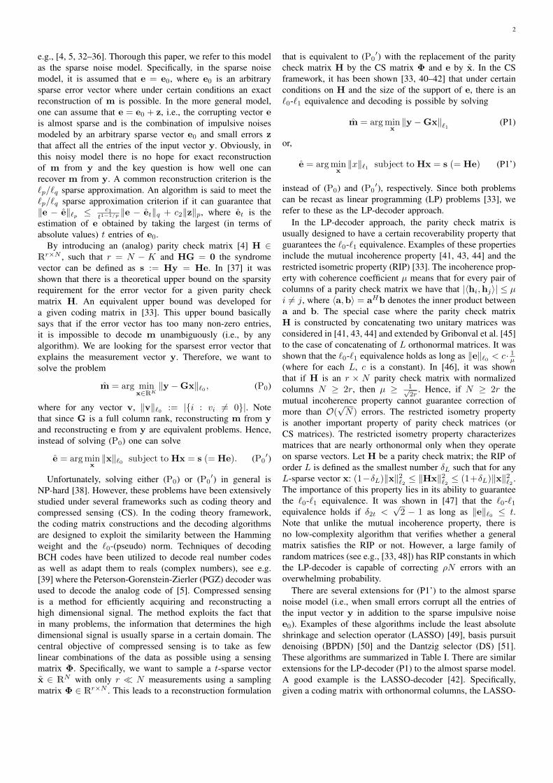
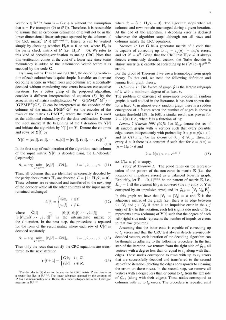
Fig. 1. An illustration of the productencoding model.
Fig. 2. An illustration of a codewordgenerated by systematic coding ma-trices G and P.
the columns and rows (respectively) indexed by S2. vec(A)is a vector constructed by stacking the columns of matrix A.Similarly, for any vector v ∈ Rc2 , vec−1(v) is a square c× cmatrix, constructed by filling in the elements of v columns bycolumns.
II. PRODUCT CODE WITH ANALOG CRC
The encoding scheme is a product code with a generatormatrix constructed by a Kronecker product of a small gener-ator matrix G ∈ Rn×k with itself
GTot = G⊗ G, (2)
where ⊗ is the Kronecker product (note that GTot ∈ Rn2×k2
).The key idea of the algorithm is the special structure of G asthe product of two matrices
G = GP, (3)
where P ∈ R(k+q)×k and G ∈ Rn×(k+q) are certain codingmatrices and q is assumed to be a small integer. Obviously, inorder to avoid a row of zeros in G, a row of G must not beorthogonal to the column space of P. To avoid any confusionfor reasons that will become clearer in what follows, we referto P as the CRC matrix and to G as the encoding matrix.
Suppose that we want to encode the information vector m ∈RK , where K = k2 and k ∈ N. Denote the codeword by
w = GTotm = (G⊗ G)m. (4)
Exploiting the Kronecker product properties, the codewordmatrix W can be written as
W = GMGT , (5)
where W := vec−1(w) and M := vec−1(m).Using the associativity of the matrix multiplication, equation
(5) can be interpreted as a two-step encoding procedure.Specifically, by writing W = (GM)GT = McolG
T =G(MGT ) = GMrow, the codeword W can be obtained byfirst encoding each column of M, using the encoding matrixG. Then, in the second step, the rows of the resulting matrixMcol are encoded, separately3. This procedure is illustrated inFig. 1. A codeword generated by systematic coding matricesG and P is illustrated in Fig. 2.
2For example: Ai and AiT denote the ith column of A and the ith rowof A, respectively.
3Alternatively, we can begin by encoding the rows of M and then in thesecond step we encode the columns of Mrow.
III. PROBLEM FORMULATION
The model of the received signal is given by
y = (G⊗ G)m+ e, (6)
where e is a certain noise vector in RN and the goal is todecode the information matrix m from the corrupted signaly. Similar to the codeword vector, it is convenient to reshapethe received signal as well as the error vector e into a n× nmatrices: Y := vec−1(y) and E := vec−1(e).
In the sparse noise model, we assume that the receivedsignal was corrupted solely by impulsive noises. Therefore,it is assumed that
e = e0, (7)
where e0 ∈ RN is an arbitrary sparse error vector. Note thatin this model, the entries of y that are not in the support ofe0 are perfectly measured 4
In the almost sparse noise model, in addition to the impul-sive errors, there are small errors affecting all entries of y.Hence, the error vector is modeled as
e = e0 + z (8)
where e0 is an arbitrary sparse vector and z represents theeffect of the small errors modeled as a Gaussian vector withi.i.d entries with distribution N (0, σ2).
IV. ANALOG TURBO DECODER FOR THE SPARSE NOISEMODEL
In this section we describe the analog Turbo decoder forthe product code described in section II for the sparse noisemodel. We will show that using an analog CRC in the encodingphase results in a code that significantly outperforms the codein [3]. Furthermore, with a few modifications, this schemecan be robust to small errors affecting all the entries of thereceived signal as will be described in section V. In the Turboalgorithm the LP-decoder (P1) is iteratively applied to eachof the rows and columns (alternately) of the received signalmatrix Y until all the errors are cleared. We use the matrixP as an analog version of the CRC that is commonly usedfor data verification in digital communication. This additionalredundancy is the key idea governing the Turbo decodingprocedure presented here and is the mechanism that makesthe iterative algorithm possible. Specifically, the CRC matrixis used for verifying successful decoding of the inner code ineach column or row before the result is transferred to the nextiteration. For instance, suppose that we have a certain vectoru = Gx+ ν, such that x = Pv. Suppose that we estimate xby solving
x = arg minx∈Rk+q
∥Gx− u∥ℓ1 . (9)
Note that this decoder does not depend on matrix P. In fact,the same LP-decoder was used in [33] to decode an arbitrary
4The expression ”impulsive noises” is often used in the literature for erasuretypes of channels in which the location of the errors is known at the receiversince the corrupted component of the received signal is completely erased(see e.g. [11]). However, following the model in e.g., [4, 5, 33] here it isassumed that impulsive noises are modeled by sparse vectors with randomsupport and arbitrary non zero values such that the location of the impulsivenoises is unknown at the receiver.
5
vector x ∈ Rk+q from u = Gx + ν without the assumptionthat x = Pv (compare (9) to (P1)). Therefore, it is reasonableto assume that an erroneous estimation of x will not be in thelower dimensional linear subspace spanned by the columns ofthe CRC matrix5 P ∈ R(k+q)×k. Hence, x can be verifiedsimply by checking whether Hpx = 0 or not, where Hp isthe parity check matrix of P (i.e., HpP = 0). We refer tothis kind of decoding-verification as analog CRC. Note thatthis verification comes at the cost of a lower rate since someredundancy is added to the information vector before it isencoded by the code G.
By using matrix P as an analog CRC, the decoding verifica-tion of each column/row is quite simple. It enables an alternatedecoding scheme in which rows and columns are sequentiallydecoded without transferring new errors between consecutiveiterations. For a better grasp of the proposed algorithm,consider a different interpretation of equation (5). By theassociativity of matrix multiplication W = G(PMPTGT ) =(GPMPT )GT , G can be interpreted as the encoder of thecolumns of the matrix PMPTGT (or the encoder of therows of the matrix GPMPT ) where the matrix P is usedas the additional redundancy for the data verification. Denotethe input matrix at the beginning of the ℓ iteration by Y[ℓ]and initiate the algorithm by Y [1] := Y. Denote the columnsand rows of Y[ℓ] by
Y[ℓ] = [c1[ℓ], c2[ℓ], · · · , cn[ℓ]] = [r1[ℓ], r2[ℓ], · · · , rn[ℓ]]T .(10)
In the first step of each iteration of the algorithm, each columnof the input matrix Y[ℓ] is decoded using the LP-decoder(separately):
xi = arg minx∈Rk+q
∥ci[ℓ]−Gx∥ℓ1 i = 1, 2, · · · , n. (11)
Then, all columns that are identified as correctly decoded bythe parity check matrix Hp are detected; C = i : Hpxi = 0.These columns are re-encoded and transferred to the next stepof the decoder while all the other columns of the input matrixremained unchanged
ci[ℓ] =
Gxi i ∈ Cci[ℓ] i /∈ C,
(12)
where C[ℓ] = [c1[ℓ], c2[ℓ], · · · , cn[ℓ]] =[r1[ℓ], r2[ℓ], · · · , rn[ℓ]]T is the intermediate matrix ofthe ℓ iteration. In the next step, the procedure is repeatedfor the rows of the result matrix where each row of C[ℓ] isdecoded separately
xi = arg minx∈Rk+q
∥ri[ℓ]−Gx∥ℓ1 i = 1, 2, · · · , n. (13)
Then only the rows that satisfy the CRC equations are trans-ferred to the next iteration
ri[ℓ+ 1] =
Gxi i ∈ Rri[ℓ] i /∈ R,
(14)
5The decoder in (9) does not depend on the CRC matrix P and results ina vector that lies in Rk+q . The linear subspace spanned by the columns ofP has a dimensionality of k. Hence, this linear subspace has a null Lebesguemeasure in Rk+q .
where R = i : Hpxi = 0. The algorithm stops when allcolumns and rows remain unchanged during a given iteration.At the end of the algorithm, a decoding error is declaredwhenever the algorithm stops although not all rows andcolumns satisfy the CRC equations.
Theorem 1: Let G be a generator matrix of a code thatis capable of correcting up to tg = tg(n) := α
√n errors,
and let N = n2. Given that the CRC test Hpx = 0 alwaysdetects erroneously decoded vectors, the Turbo decoder isalmost surely (a.s) capable of correcting up to t(N) > α
4N0.75
errors.For the proof of Theorem 1 we use a terminology from graphtheory. To that end, we need the following definition andlemma from graph theory.
Definition 1: The k-core of graph G is the largest subgraphof G with a minimum degree of at least k.The problem of existence of non-empty k-cores in randomgraphs is well studied in the literature. It has been shown thatfor a fixed k, in almost every random graph there is a suddenemergence of a k-core when the number of edges is above acertain threshold [59]. In [60], a similar result was proven fork = k(n) (i.e., when k is a function of n):
Lemma 2 (Luczak 1991 [60]): Let Gn,p denote the set ofall random graphs with n vertices such that every possibleedge occurs independently with probability 0 < p = p(n) < 1and let C(k, n, p) be the k-core of Gn,p ∈ Gn,p. Then, forevery δ > 0 there is a constant d such that for c = c(n) =(n− 1)p > d and
k = k(n) > c+ c0.5+δ (15)
a.s C(k, n, p) is empty.Proof of Theorem 1: The proof relies on the represen-
tation of the pattern of the non-zeros in matrix E (i.e., thelocation of impulsive errors) as a balanced bipartite graph.Explicitly, let E ∈ 0, 1n×n be the pattern of matrix E, i.e.,Ei,j = 1 iff the element Ei,j is non-zero (the i, j entry of Y iscorrupted by an impulsive error) and let Gb.b =
(V1,V2, E
).
In this graph we have that |V1| = |V2| = n and E is theadjacency matrix of the graph (i.e., there is an edge betweeni ∈ V1 and j ∈ V2 if there is an impulsive error in the i, jentry of E). In this notation, each left (right) side node of Gb.b
represents a row (column) of Y[ℓ] such that the degree of eachleft (right) side node represents the number of impulsive errorsin that row (column).
Assuming that the inner code is capable of correcting upto tg errors and that the CRC test always detects erroneouslydecoded vectors, each iteration of the decoding algorithm canbe thought as adhering to the following procedure. In the firststep of the iteration, we remove from the right side of Gb.b allvertices with a degree less than or equal to tg along with theiredges. These nodes correspond to rows with up to tg errorsthat are successfully decoded and transferred to the secondstep of the iteration (deleting the edges corresponds to cleaningthe errors on those rows). In the second step, we remove allvertices with a degree less than or equal to tg from the left sideof Gb.b (along with their edges). These nodes correspond tocolumns with up to tg errors. The procedure is repeated until
6
no more vertices with degree less than or equal to tg remain.In graph theory terminology, this procedure is applied to findthe (tg + 1)-core of Gb.b, see [61]. If the resulting (tg + 1)-core is empty, the algorithm cleaned all the impulsive errors.In other words, the turbo decoder fails only if the (tg+1)-coreof Gb.b is non-empty.
From Lemma 2, it is known that in almost every randomgraph in G2n,p0 the (tg + 1)-core is empty for p0 = p0(n) =α2
√n
2n−1 . This can be obtained by choosing δ = 0.5 and hencefor p0 = α
2
√n
2n−1 the RHS of (15) becomes 2c = α√n <
tg+1 (note that for any constant d and n large enough c(n) >d). This result implies that the (tg + 1)-core in almost everybalanced bipartite graph with 2n vertices is empty if everypossible edge occurs independently with probability p0
6. Sincethe property of having an empty t-core is a convex property,there is an empty (tg+1)-core in almost every random bipartitegraph with fewer than M(n) := n2p0 > α
4 n1.5 edges (see
Theorem 2.2 in [61]; the proof remains valid for the bipartitecase as well). The claim now follows from the relation n =√N .Theorem 3: Given that the CRC test Hpx = 0 always
detects erroneously decoded vectors, the complexity of theTurbo algorithm is at most O
(N2.75
).
Proof: It is known that the complexity of decoding the ℓ1-decoder (11) and (13) for the inner code is f(n) = O
(n3.5
)operations. Hence, decoding of the inner code is the mostdominant in terms of complexity. Therefore, the overall com-plexity of each iteration in the Turbo algorithm is O (nf (n)).Since n =
√N , we have that the complexity of each iteration
is at most O(√
Nf(√N)
)= O
(N2.25
)operations. In each
iteration at least one column or row is transferred to the nextiteration (otherwise, the algorithm is terminated). There aren =
√N such rows and columns. Hence, the maximal number
of iterations is√N . The claim now follows.
In the following, we discuss some implementation issuesregarding the decoding algorithm.
Observation 1: Note that the matrix-vector multiplicationin the re-encoding stages of the algorithm (i.e., equations (12)and (14)) were presented for explanatory purposes alone. Infact, by noting that equation (11) can be re-written as
(xi, ei) = arg minx∈Rk+q
e∈Rn
∥e∥ℓ1 subject to e = ci[ℓ]−Gx,
(16)for all i re-encoding xi can be written as ci[ℓ] = ci[ℓ] − ei.The same argument can be applied to equation (13).
Also note that there is no need to decode the columns ofY[ℓ] which are already codewords of G. These columns canbe directly transferred to the next step of the algorithm. Acolumn is directly transferred to the next step of the algorithmif HGci = 0n−k, where HG ∈ R(n−k)×n is the parity checkmatrix of G; i.e., it is a full rank matrix and HGG = 0. Thesame argument can be applied to the rows of C.
Finally, throughout this paper we have assumed that thedecoding in each stage of a column or a row is done by an
6To see why this is true, note that any bipartite graph is an induced subgraphof G2n,p by removing edges between vertices on the same side.
LP-decoder. However, any other algorithm that solves the ℓ0minimization (P0) under appropriate conditions can be usedas well e.g., basis pursuit (BP) [50], matching pursuit (MP)[62] and orthogonal MP (OMP) [63].
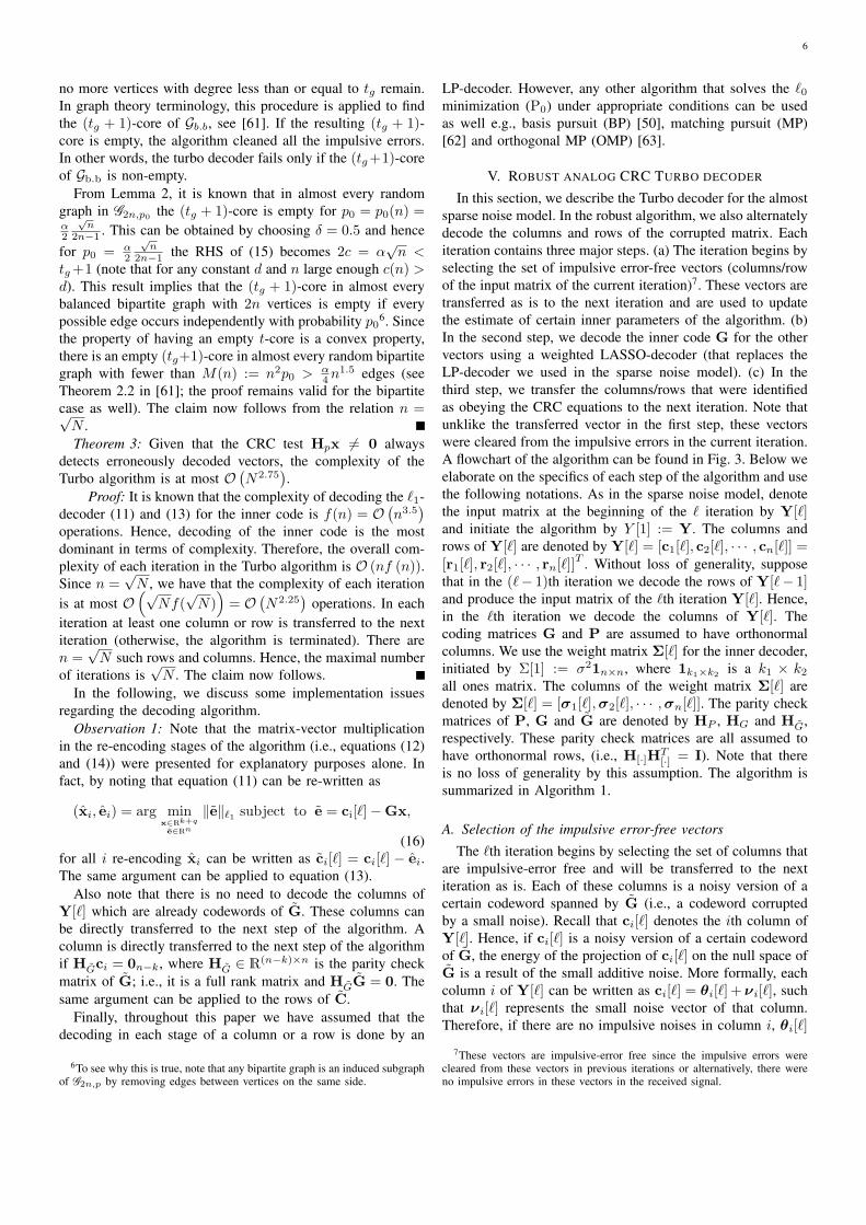
V. ROBUST ANALOG CRC TURBO DECODER
In this section, we describe the Turbo decoder for the almostsparse noise model. In the robust algorithm, we also alternatelydecode the columns and rows of the corrupted matrix. Eachiteration contains three major steps. (a) The iteration begins byselecting the set of impulsive error-free vectors (columns/rowof the input matrix of the current iteration)7. These vectors aretransferred as is to the next iteration and are used to updatethe estimate of certain inner parameters of the algorithm. (b)In the second step, we decode the inner code G for the othervectors using a weighted LASSO-decoder (that replaces theLP-decoder we used in the sparse noise model). (c) In thethird step, we transfer the columns/rows that were identifiedas obeying the CRC equations to the next iteration. Note thatunklike the transferred vector in the first step, these vectorswere cleared from the impulsive errors in the current iteration.A flowchart of the algorithm can be found in Fig. 3. Below weelaborate on the specifics of each step of the algorithm and usethe following notations. As in the sparse noise model, denotethe input matrix at the beginning of the ℓ iteration by Y[ℓ]and initiate the algorithm by Y [1] := Y. The columns androws of Y[ℓ] are denoted by Y[ℓ] = [c1[ℓ], c2[ℓ], · · · , cn[ℓ]] =[r1[ℓ], r2[ℓ], · · · , rn[ℓ]]T . Without loss of generality, supposethat in the (ℓ− 1)th iteration we decode the rows of Y[ℓ− 1]and produce the input matrix of the ℓth iteration Y[ℓ]. Hence,in the ℓth iteration we decode the columns of Y[ℓ]. Thecoding matrices G and P are assumed to have orthonormalcolumns. We use the weight matrix Σ[ℓ] for the inner decoder,initiated by Σ[1] := σ21n×n, where 1k1×k2 is a k1 × k2all ones matrix. The columns of the weight matrix Σ[ℓ] aredenoted by Σ[ℓ] = [σ1[ℓ],σ2[ℓ], · · · ,σn[ℓ]]. The parity checkmatrices of P, G and G are denoted by HP , HG and HG,respectively. These parity check matrices are all assumed tohave orthonormal rows, (i.e., H[·]H
T[·] = I). Note that there
is no loss of generality by this assumption. The algorithm issummarized in Algorithm 1.
A. Selection of the impulsive error-free vectors
The ℓth iteration begins by selecting the set of columns thatare impulsive-error free and will be transferred to the nextiteration as is. Each of these columns is a noisy version of acertain codeword spanned by G (i.e., a codeword corruptedby a small noise). Recall that ci[ℓ] denotes the ith column ofY[ℓ]. Hence, if ci[ℓ] is a noisy version of a certain codewordof G, the energy of the projection of ci[ℓ] on the null space ofG is a result of the small additive noise. More formally, eachcolumn i of Y[ℓ] can be written as ci[ℓ] = θi[ℓ] + νi[ℓ], suchthat νi[ℓ] represents the small noise vector of that column.Therefore, if there are no impulsive noises in column i, θi[ℓ]
7These vectors are impulsive-error free since the impulsive errors werecleared from these vectors in previous iterations or alternatively, there wereno impulsive errors in these vectors in the received signal.
7
Fig. 3. A flowchart of the robust Turbo decoder.
is spanned by the columns of G. Therefore, selecting the set ofimpulsive-error free columns is essentially a detection problemfor each column with the following two hypotheses:
H0 : HGθ = 0H1 : HGθ = 0
(17)
where HG is the parity check matrix of G. Hence, using anenergy detector8 one decides H1 if
cTi [ℓ]PTHPHci[ℓ] = cTi [ℓ]PHci[ℓ] > γℓ, (18)
for a certain threshold γℓ, where PH = HTG(HGH
TG)−1HG
is the projection matrix onto the subspace spanned by thecolumns of HG.
In the first iteration, Y[1] is the received signal andtherefore, each column i can be written as ci[1] =(GPMPTGT +E
)i+ Zi and recall that Zi ∼ N (0, σ2I).
Hence, for Y[1], (17) is a detection problem for a classicallinear model with a well known generalized likelihood ratiotest (GLRT) (see e.g., Theorem 7.1 in [65]) that coincideswith the energy detector (18). Specifically, the GLRT for theproblem is to decide H1 if
ci[1]THT
G(HGHT
G)−1HGci[1]
σ2 > γ′1,where γ′1 is chosen such that we have a certain predeterminedprobability of dropping an impulsive-error free column. Note
8For simplicity of presentation, we did not optimize the detection processof the impulsive-error free vectors (or the CRC verification in section V-D).As an alternative to the energy detectors suggested here, one may considerusing e.g., compressive constant false alarm rate (CFAR) radar detectors [64].
that this predetermined probability is the probability of thefalse alarm of the detector. Therefore, these kinds of detectorsare also known as CFAR detectors. In [65] it was shownthat this predetermined probability is given by the right-tailed probability function of a central X 2
q random variableand denoted by QX 2
q(γ′1). Therefore, γ1 can be chosen as
γ1 = γ′1σ2.
For ℓ > 1, the entries of Y[ℓ] were obtained in previousiterations as the result of decoded rows or columns. Therefore,the small errors on Y[ℓ] cannot be modeled as Gaussiandistributed as we did in the first iteration. However, we can useγℓ = c · γ1 for a certain small constant c as the threshold forℓ > 1. This choice of threshold implies that we can transfera column to the next iteration and tolerate small noises witha projected energy of up to c · γ1 on the null space of G.Note that for small values of c we transfer fewer vectorsto the next iteration, which leads to slower convergence ofthe algorithm since fewer vectors are identified as clean fromimpulsive errors while setting c to be a large value may lead toa transfer of high value errors to the next iteration. However, ifthere were not too many such vectors these wrongly transferredvectors can be corrected in the next iterations. Empiricalexperiments suggest that the algorithm converges quite wellwhen 3 ≤ c ≤ 5.
By using the fact that the rows of HG are orthonormal,the GLRT/energy-detector can be simplified and rewritten asan energy detector that is applied to the syndrome vector of
8
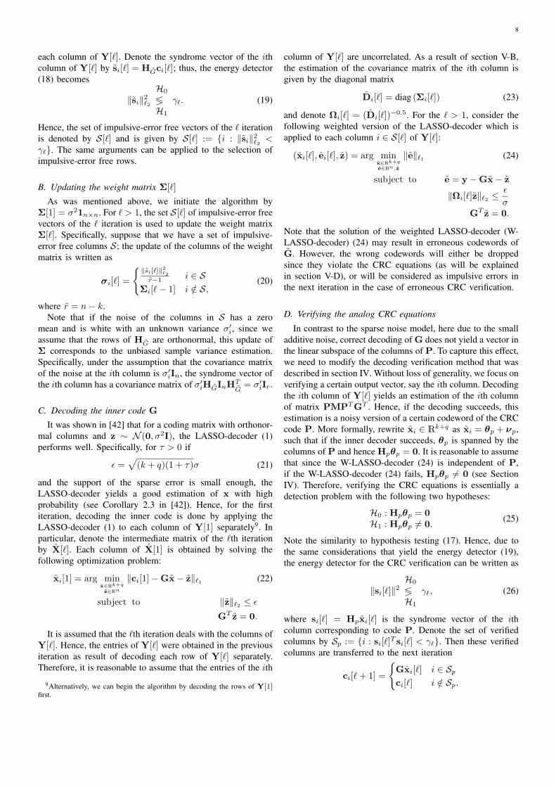
each column of Y[ℓ]. Denote the syndrome vector of the ithcolumn of Y[ℓ] by si[ℓ] = HGci[ℓ]; thus, the energy detector(18) becomes
∥si∥2ℓ2H0
≶H1
γℓ. (19)
Hence, the set of impulsive-error free vectors of the ℓ iterationis denoted by S[ℓ] and is given by S[ℓ] := i : ∥si∥2ℓ2 <γℓ. The same arguments can be applied to the selection ofimpulsive-error free rows.
B. Updating the weight matrix Σ[ℓ]
As was mentioned above, we initiate the algorithm byΣ[1] = σ21n×n. For ℓ > 1, the set S[ℓ] of impulsive-error freevectors of the ℓ iteration is used to update the weight matrixΣ[ℓ]. Specifically, suppose that we have a set of impulsive-error free columns S; the update of the columns of the weightmatrix is written as
σi[ℓ] =
∥si[ℓ]∥2ℓ2
r−1 i ∈ SΣi[ℓ− 1] i /∈ S,
(20)
where r = n− k.Note that if the noise of the columns in S has a zero
mean and is white with an unknown variance σ′i, since weassume that the rows of HG are orthonormal, this update ofΣ corresponds to the unbiased sample variance estimation.Specifically, under the assumption that the covariance matrixof the noise at the ith column is σ′iIn, the syndrome vector ofthe ith column has a covariance matrix of σ′iHGInH
TG= σ′iIr.
C. Decoding the inner code G
It was shown in [42] that for a coding matrix with orthonor-mal columns and z ∼ N (0, σ2I), the LASSO-decoder (1)performs well. Specifically, for τ > 0 if
ϵ =√(k + q)(1 + τ)σ (21)
and the support of the sparse error is small enough, theLASSO-decoder yields a good estimation of x with highprobability (see Corollary 2.3 in [42]). Hence, for the firstiteration, decoding the inner code is done by applying theLASSO-decoder (1) to each column of Y[1] separately9. Inparticular, denote the intermediate matrix of the ℓth iterationby X[ℓ]. Each column of X[1] is obtained by solving thefollowing optimization problem:
xi[1] = arg minx∈Rk+q
z∈Rn
∥ci[1]−Gx− z∥ℓ1 (22)
subject to ∥z∥ℓ2 ≤ ϵ
GT z = 0.
It is assumed that the ℓth iteration deals with the columns ofY[ℓ]. Hence, the entries of Y[ℓ] were obtained in the previousiteration as result of decoding each row of Y[ℓ] separately.Therefore, it is reasonable to assume that the entries of the ith
9Alternatively, we can begin the algorithm by decoding the rows of Y[1]first.
column of Y[ℓ] are uncorrelated. As a result of section V-B,the estimation of the covariance matrix of the ith column isgiven by the diagonal matrix
Di[ℓ] = diag (Σi[ℓ]) (23)
and denote Ωi[ℓ] = (Di[ℓ])−0.5. For the ℓ > 1, consider the
following weighted version of the LASSO-decoder which isapplied to each column i ∈ S[ℓ] of Y[ℓ]:
(xi[ℓ], ei[ℓ], z) = arg minx∈Rk+q
e∈Rn,z
∥e∥ℓ1 (24)
subject to e = y −Gx− z
∥Ωi[ℓ]z∥ℓ2 ≤ ϵ
σGT z = 0.
Note that the solution of the weighted LASSO-decoder (W-LASSO-decoder) (24) may result in erroneous codewords ofG. However, the wrong codewords will either be droppedsince they violate the CRC equations (as will be explainedin section V-D), or will be considered as impulsive errors inthe next iteration in the case of erroneous CRC verification.
D. Verifying the analog CRC equations
In contrast to the sparse noise model, here due to the smalladditive noise, correct decoding of G does not yield a vector inthe linear subspace of the columns of P. To capture this effect,we need to modify the decoding verification method that wasdescribed in section IV. Without loss of generality, we focus onverifying a certain output vector, say the ith column. Decodingthe ith column of Y[ℓ] yields an estimation of the ith columnof matrix PMPTGT . Hence, if the decoding succeeds, thisestimation is a noisy version of a certain codeword of the CRCcode P. More formally, rewrite xi ∈ Rk+q as xi = θp + νp,such that if the inner decoder succeeds, θp is spanned by thecolumns of P and hence Hpθp = 0. It is reasonable to assumethat since the W-LASSO-decoder (24) is independent of P,if the W-LASSO-decoder (24) fails, Hpθp = 0 (see SectionIV). Therefore, verifying the CRC equations is essentially adetection problem with the following two hypotheses:
H0 : Hpθp = 0H1 : Hpθp = 0.
(25)
Note the similarity to hypothesis testing (17). Hence, due tothe same considerations that yield the energy detector (19),the energy detector for the CRC verification can be written as
∥si[ℓ]∥2H0
≶H1
γℓ, (26)
where si[ℓ] = Hpxi[ℓ] is the syndrome vector of the ithcolumn corresponding to code P. Denote the set of verifiedcolumns by Sp := i : si[ℓ]T si[ℓ] < γℓ. Then these verifiedcolumns are transferred to the next iteration
ci[ℓ+ 1] =
Gxi[ℓ] i ∈ Sp
ci[ℓ] i /∈ Sp.
9
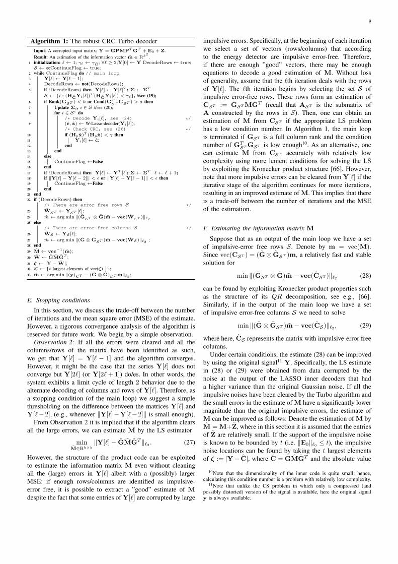
Algorithm 1: The robust CRC Turbo decoderInput: A corrupted input matrix: Y = GPMPTGT + E0 + Z.Result: An estimation of the information vector m ∈ Rk2
.1 initialization: ℓ← 1; γℓ ← γG; ∀ℓ ≥ 2;Y[0]← Y DecodeRows← true;S ← ϕ;ContinueFlag← true;
2 while ContinueFlag do // main loop3 Y[ℓ]← Y[ℓ− 1];4 DecodeRows← not(DecodeRows);5 if (DecodeRows) then Y[ℓ]← Y[ℓ]T ; Σ← ΣT
S ← i : (HGYi[ℓ])T (HGYi[ℓ]) < γℓ, //see (19);
6 if Rank(GST ) < k or Cond(GTST GST ) > a then
7 Update Σi, i ∈ S //see (20);8 for i ∈ Sc do
/* Decode Yi[ℓ], see (24) */9 (c, x)← W-Lasso-decoder(Yi[ℓ]);
/* Check CRC, see (26) */10 if (Hpx)
T (Hpx) < γ then11 Yi[ℓ]← c;12 end13 end14 else15 ContinueFlag←False16 end17 if (DecodeRows) then Y[ℓ]← YT [ℓ]; Σ← ΣT ℓ← ℓ + 1;18 if ∥Y[ℓ]−Y[ℓ− 2]∥ < ϵ or ∥Y[ℓ]−Y[ℓ− 1]∥ < ϵ then19 ContinueFlag←False20 end21 end22 if (DecodeRows) then
/* There are error free rows S */23 WST ← YST [ℓ];24 m← argmin ∥(GST ⊗ G)m− vec(WST )∥ℓ225 else
/* There are error free columns S */26 WS ← YS [ℓ];27 m← argmin ∥(G⊗ GST )m− vec(WS)∥ℓ2 ;28 end29 M← vec−1(m);30 W ← GMGT ;31 ζ ← |Y − W|;32 K ← t largest elements of vec(ζ) c;33 m← argmin ∥(y)KT − (G⊗ G)KT m∥ℓ2 ;
E. Stopping conditions
In this section, we discuss the trade-off between the numberof iterations and the mean square error (MSE) of the estimate.However, a rigorous convergence analysis of the algorithm isreserved for future work. We begin by a simple observation.
Observation 2: If all the errors were cleared and all thecolumns/rows of the matrix have been identified as such,we get that Y[ℓ] = Y[ℓ − 1] and the algorithm converges.However, it might be the case that the series Y[ℓ] does notconverge but Y[2ℓ] (or Y[2ℓ+ 1]) do/es. In other words, thesystem exhibits a limit cycle of length 2 behavior due to thealternate decoding of columns and rows of Y[ℓ]. Therefore, asa stopping condition (of the main loop) we suggest a simplethresholding on the difference between the matrices Y[ℓ] andY[ℓ− 2], (e.g., whenever ∥Y[ℓ]−Y[ℓ− 2]∥ is small enough).
From Observation 2 it is implied that if the algorithm clearsall the large errors, we can estimate M by the LS estimator
minM∈Rk×k
∥Y[ℓ]− GMGT ∥ℓ2 . (27)
However, the structure of the product code can be exploitedto estimate the information matrix M even without cleaningall the (large) errors in Y[ℓ] albeit with a (possibly) largerMSE: if enough rows/columns are identified as impulsive-error free, it is possible to extract a ”good” estimate of Mdespite the fact that some entries of Y[ℓ] are corrupted by large
impulsive errors. Specifically, at the beginning of each iterationwe select a set of vectors (rows/columns) that accordingto the energy detector are impulsive error-free. Therefore,if there are enough ”good” vectors, there may be enoughequations to decode a good estimation of M. Without lossof generality, assume that the ℓth iteration deals with the rowsof Y[ℓ]. The ℓth iteration begins by selecting the set S ofimpulsive error-free rows. These rows form an estimation ofCST := GSTMGT (recall that AST is the submatrix ofA constructed by the rows in S). Then, one can obtain anestimation of M from CST if the appropriate LS problemhas a low condition number. In Algorithm 1, the main loopis terminated if GST is a full column rank and the conditionnumber of GT
STGST is low enough10. As an alternative, onecan estimate M from CST accurately with relatively lowcomplexity using more lenient conditions for solving the LSby exploiting the Kronecker product structure [66]. However,note that more impulsive errors can be cleared from Y[ℓ] if theiterative stage of the algorithm continues for more iterations,resulting in an improved estimate of M. This implies that thereis a trade-off between the number of iterations and the MSEof the estimation.
F. Estimating the information matrix M
Suppose that as an output of the main loop we have a setof impulsive-error free rows S. Denote by m = vec(M).Since vec(CST) = (G⊗ GST )m, a relatively fast and stablesolution for
min ∥(GST ⊗ G)m− vec(CST)∥ℓ2 (28)
can be found by exploiting Kronecker product properties suchas the structure of its QR decomposition, see e.g., [66].Similarly, if in the output of the main loop we have a setof impulsive error-free columns S we need to solve
min ∥(G⊗ GST )m− vec(CS)∥ℓ2 , (29)
where here, CS represents the matrix with impulsive-error freecolumns.
Under certain conditions, the estimate (28) can be improvedby using the original signal11 Y. Specifically, the LS estimatein (28) or (29) were obtained from data corrupted by thenoise at the output of the LASSO inner decoders that hada higher variance than the original Gaussian noise. If all theimpulsive noises have been cleared by the Turbo algorithm andthe small errors in the estimate of M have a significantly lowermagnitude than the original impulsive errors, the estimate ofM can be improved as follows: Denote the estimation of M byM = M+Z, where in this section it is assumed that the entriesof Z are relatively small. If the support of the impulsive noiseis known to be bounded by t (i.e. ∥E0∥ℓ0 ≤ t), the impulsivenoise locations can be found by taking the t largest elementsof ζ := |Y− C|, where C = GMGT and the absolute value
10Note that the dimensionality of the inner code is quite small; hence,calculating this condition number is a problem with relatively low complexity.
11Note that unlike the CS problem in which only a compressed (andpossibly distorted) version of the signal is available, here the original signaly is always available.

10
of the matrix is calculated element-wise. Then, by deletingthese t entries from Y we can find a better estimate of Mby solving the appropriate LS problem. Specifically, denotethe set of the t largest elements of vec(ζ) by S. Deleting theappropriate entries of Y yields the following LS problem:
minm∈Rk2
∥yKT − (G⊗ G)KTm∥ℓ2 , (30)
where y := vec(Y) and K := Sc is the complement of S.Assuming that there are no (large) errors in the entries of yKT ,the LS problem (30) is composed of a set of equations that iscorrupted by the original AWGN (which has a lower varianceσ2). Therefore, it is expected that the solution of (30) has alower MSE than the LS estimates in (28) or (29). However,note that since the impulsive errors have no structure (30)cannot be solved efficiently by exploiting the properties of theKronecker product.
VI. SIMULATION RESULTS
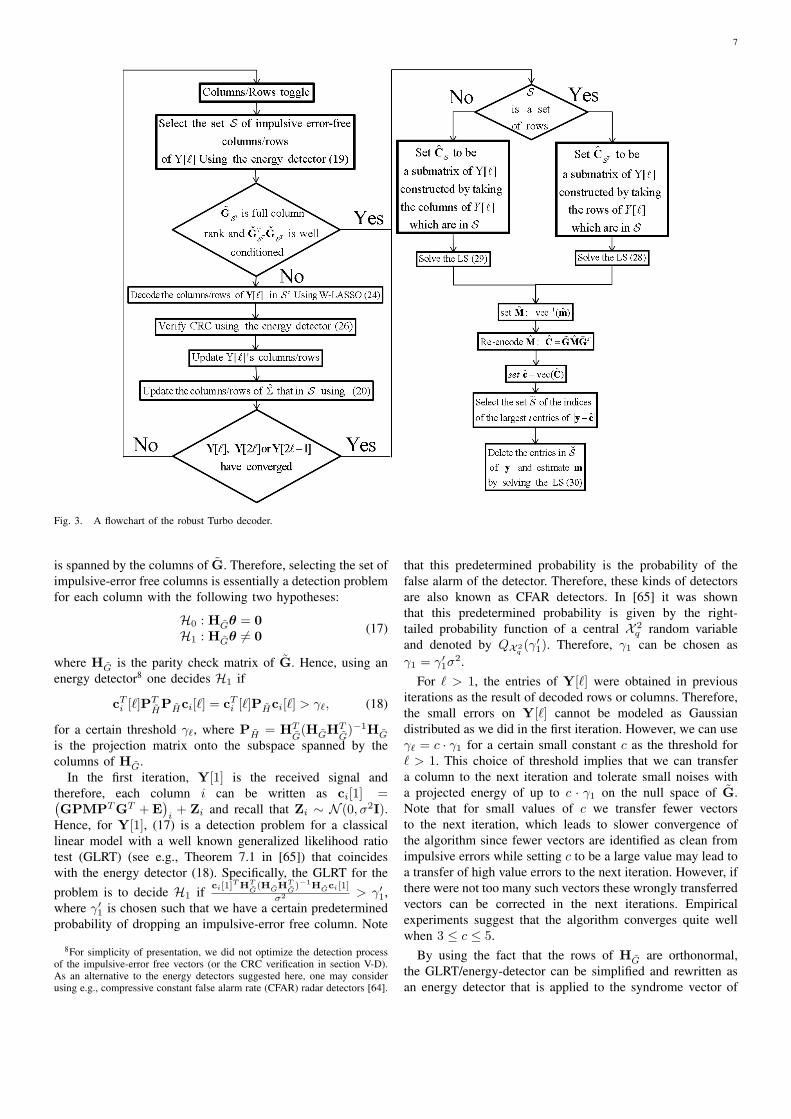
In this section, we present some simulation results thatillustrate the performance of the analog Turbo decoding al-gorithms. For both algorithms, the k × k information matrixwas constructed by selecting a 23-PAM (pulse-amplitude mod-ulation) symbol for each entry (M)i,j ∈ ±1,±3, · · · ± 7uniformly and independently at random. Then, the informationmatrix M = (Mi,j) was encoded as was explained in equation(5) to produce an n × n codeword matrix. Each codewordwas corrupted according to the appropriate noise model anddecoded using the relevant Turbo algorithm. In the impulsivenoise model, we compared the Turbo code using variants oncode constructions and decoding methods of the inner coedto the code in [3] and to the one-step LP-decoder [33]. Inthe almost sparse noise model, the results were compared tothe oracle bound (i.e., when the impulsive noise locations andamplitude are perfectly known to the receiver).
A. The Turbo algorithm under the impulsive noise model
Under the sparse noise model we used two sets of simula-tions. First, we compared the performance of the Turbo algo-rithm to the two-step decoder [3] using a mutual incoherence-based construction for the inner code. Like the encodingscheme presented in section II, the algorithm in [3] is usedto decode a product code with a generator matrix of the formG ⊗G. Since in [3] there is no CRC matrix that inserts theadditional redundancy required by the Turbo algorithm, thedecoding phase of [3] is composed of only two simple steps:(a) decoding the column of the input matrix by applying (P1)to each column of the input matrix, (b) decoding each rowof the resulting matrix using (P1). To illustrate the advantagesof sacrificing q symbols in each row and column for CRCverification in the encoding phase and the additional operationsrequired for the iterative algorithm in the decoding phase, wecompared the two step decoder and the turbo algorithm whenthey both had the same generator matrix G but each algorithmwas tested with a different size information matrix M. Thisenabled us to compare the Turbo decoder and the two-stepdecoder on codewords having the same size. However, since
in this setup the Turbo code has a lower coding rate, weconstructed a lower-rate generator matrix Glow for the innercode of the two-step product code, resulting in a code thathad (approximately) the same rate as the Turbo code. Forthe coding matrix G, we used a mutual incoherence-based(deterministic) construction composed of an Identity matrixand a Hadamard matrix of size n
2 each [41, 45]. This codingmatrix was shown to correctly decode all t-sparse error vectorsas long as t ≤ α
√n (where α ≈ 0.65 [45]). Denote the parity
check matrix of G by H (i.e., HG = 0) and construct a paritycheck matrix Hlow by taking the first n columns of H, wheren is chosen such that the new code has (approximately) thesame code rate as G = GP. Then, the coding matrix Glow ischosen such that it is in the null space of the matrix Hlow. Inthe two-step decoder, we encoded a n
2 ×n2 information matrix
for the higher rate product code and a k×k information matrixfor the lower rate product code. These information matriceswere produced by using the same constellation of 23-PAM weimplemented in the Turbo code. Following Observation 1, wetested the Turbo decoder in this setup also using the OMPalgorithm for decoding the inner code.
Next, the Turbo algorithm was tested using a random innercode. In particular, we used a generator matrix G±1 in the nullspace of a random parity check matrix H±1 with i.i.d entriessuch that Pr(hi,j = 1/
√r) = Pr(hi,j = −1/
√r) = 0.5 12.
For comparison, we encoded an information vector of size k2
using a full random n2 × k2 generator matrix13
All codewords were corrupted by a t-sparse error matrixof the appropriate size, constructed by choosing a support ofsize t uniformly at random and values that are i.i.d. Gaussian.Then, the corrupted codewords were decoded (each by theappropriate decoder). The results are shown in Fig. 4 for thecase where k = 15, q = 1, n = 32, k = 14 and n = 30. Eachpoint represents the frequency of correct reconstruction of theinformation matrix (out of 1000 trials).
As can be seen in Fig. 4, in the mutual incoherence-basedsetup, the Turbo decoder is capable of correcting error vectorswith support that is much larger than the code in [3]. Thisimprovement was made possible by the iterative operation ofthe algorithm and the use of the analog CRC. Using a randomcode for the inner code improves the correcting capabilityof the Turbo code. However, in the random constructionof G we needed to store the 32 × 15 matrix in both thetransmitter and receiver. It is worth mentioning that we used arandom construction for matrix Q. However, since the mutualincoherence-based construction of G was deterministic, theoverhead was relatively small because we only needed tostore a random vector of length 1 × 15 entries for a blockwith 32 × 32 entries. It is obvious that the one-step fullrandom code outperforms the Turbo decoder in terms of itscorrecting capability. However, the complexity of the decoderis much higher (see Theorem 3). Moreover, for the full randomapproach we need to store the 322×152 entries of the random
12Note that from [48], it is known that such ±1 random matrices satisfythe RIP with a probability that goes to 1 with the increasing n.
13We first constructed a Gaussian parity check matrix HGuassian thatsatisfies the RIP with high probability cf. [33], then G was constructed tospan the null space of HGuassian.

11
matrix. Combining the OMP with the Turbo algorithm whileusing a mutual-incoherence construction for the inner coderesulted in a very strong coding technique. This was somewhatsurprising since the mutual-incoherence construction guaran-tees a correcting capability of O
(√N)
errors using both theLP decoder and the OMP [63]. However, while it was evidentthat both algorithms had the same breakpoint, the inner OMPdecoder corrected denser error vectors than the LP-decodermore frequently. Hence, more errors were cleaned during eachiteration of the Turbo algorithm using the OMP algorithm.
Finally, it should be noted that in the proof of Theorem3 we bounded the number of iterations of the algorithm by√N = 32. However, the average number of iterations was
below 5 in all the setups.
||e||ℓ0/N0 0.05 0.1 0.15 0.2 0.25 0.3 0.35 0.4 0.45 0.5
freq
uenc
y of
exa
ct d
ecod
ing
(out
of 1
000
tria
ls)
0
0.1
0.2
0.3
0.4
0.5
0.6
0.7
0.8
0.9
1
Turbo N=322 K=152 rate~0.2197
Two-step N=302 K=142 rate~0.2178
Two-step n=322 k=162 rate 0.25Random one-step LP decoder
N=322 K=152 rate~0.2197Turbo (random)
N=322 K=152 rate~0.2197
Turbo (OMP) N=322 K=152 rate~0.2197
Fig. 4. Comparison of various of decoding algorithms under the sparse noisemodel.
B. The robust Turbo algorithm under the almost sparse noisemodel
In this section we illustrate how well the robust Turbodecoder performs. In the first set of simulations we tested therobust Turbo decoder for various values of the signal to thenon-impulsive noise ratio and fixed the number of impulsiveerrors. In the second set, we fixed the signal to the non-impulsive noise ratio and tested the algorithm for varioussupport sizes of the sparse error.
For the coding matrix G we used a mutual incoherence-based (deterministic) construction composed of an Identitymatrix and a Hadamard matrix of size n
2 each and normalizedits columns, where n = 128. The orthonormal matrix P wasconstructed by taking the first k = 59 columns of the 64× 64
unitary matrix of the QR decomposition of P =[I Q
]T,
where Q ∈ Rk×q has ±1 elements with equal probabilityi.i.d (i.e., Pr
((Q)i,j = 1
)= Pr
((Q)i,j = −1
)= 0.5).
The input matrix Y was a corrupted version of the rescaledcodeword Y =
√EsGMGT +E0+Z, where Es = 21
(d2
)2is the average symbol energy14 and we fixed d = 2/
√21. We
also fixed the size of the support of the impulsive error to 2500(such that approximately 15% of the block size was corrupted
14Note the since we used coding matrices with orthonormal columns theaverage energy remained unchanged after we encoded the information block.
SNR [dB]15 16 17 18 19 20 21 22 23 24 25 26
SE
R
10-3
10-2
10-1
Robust Turbo (15% large errors)Robust Turbo (15% small errors)LS(no impulsive noises)
Fig. 5. SER for 23-PAM at the output of the turbo decoder with largeamplitude impulsive noise and very small impulsive errors.
by the impulsive errors). The values of the non-zero elementsof E0 were ±1.8/
√21 with equal probability, independently
of each other. We chose a magnitude of 1.8/√21 such that
it was strong enough to cause interference to the signal butnot too strong to be located when applying a simple energydetector on the corrupted signal y. The AWGN was assumedto have a variance of σ2. The parameters for the algorithmwere chosen as follows: the LASSO ϵ (see equation (21)) waschosen by setting τ := 1. The detector thresholds (i.e., the γ-s)were chosen such that we had a 10% probability of droppinga good vector; γ1, the threshold for the first iteration, wasdesigned for noise with a variance of σ2 as the variance ofthe input noise. For all the other thresholds, we designed thedetector under the assumption that the noise had a varianceof 5σ2. The threshold for exiting the main loop using thecondition number (see line 6 in Algorithm 1) was set to a =1.9. Note that Cond(GT
S GS) > 1.9 for approximately 80%of the submatrices GS when |S| = n− 1.
We compared the results of the Turbo decoder in this setupto the case where E0 is perfectly known to the receiver andLS was performed on the received signal. Note that whenthe impulsive errors are known, the error at the output of thecorresponding LS problem has the same variance as Z (thisis a direct consequence of the use of coding matrices withorthonormal columns). Therefore, the theoretical symbol error
rate (SER) in this case is given by SERLS = 148 Q
(√SNR21
).
The results are shown in Fig. 5 where each point representsthe average SER in the output of the Turbo decoder (out of100 transmitted codewords, each of which is encoded from59 × 59 23-PAM symbols). As can be seen, despite the factthat the input signal had approximately 15% corrupted entries,the SER at the output of the turbo algorithm had only 1dBloss compared to the case where the impulsive errors wereperfectly known to the receiver and a LS was performed onthe input signal after removing these errors. It should be notedthat upon knowing E0 perfectly, the LS problem had 15%measurements more than the Turbo decoder since in last stepof the turbo decoder, we dropped t = 2500 entries of y (seethe last line in Algorithm 1). This result is consistent with theMSE at the output of the Turbo decoder (before decoding thePAM symbols), see Fig. 6.

12
SNR [dB]14 15 16 17 18 19 20 21 22 23 24 25
log10(‖m
−m‖2/k2)
-2.5
-2.4
-2.3
-2.2
-2.1
-2
-1.9
-1.8
-1.7
-1.6
-1.5
-1.4
average MSE - Turbo decoder‖e‖ℓ0 = 2500
Theoretical average MSE - LS(no impulsive noises)
Fig. 6. Average MSE at the output of the turbo decoder.
‖e‖ℓ0/N0.1 0.12 0.14 0.16 0.18 0.2 0.22 0.24
SE
R
10-3
10-2
10-1
‖e‖ℓ0/N0.1 0.12 0.14 0.16 0.18 0.2 0.22 0.24lo
g10(‖m
−m‖2/k2)
-2
-1.5
-1
-0.5
(a)
(b)
Fig. 7. (a) SER for 23-PAM at the output of the turbo decoder versus thesupport of the error vector. (b) Average MSE at the output of the turbo decoderversus the support of the error vector.
We next illustrate how well the robust Turbo decoderperforms when the SNR is fixed and the support size of thesparse error increases. The results for the SER and the averageMSE are depicted in Fig. 7(a) and Fig. 7(b), respectively. Inthe last part of the simulation, we illustrate the performance ofthe Turbo algorithm when we violated one of the assumptionswe made in section V-F. Specifically, we assumed that thesmall errors in the estimate of M (the estimation as it ispresented before line 29 in Algorithm 1) had a significantlylower magnitude than the original impulsive errors. In thispart of the simulation we examined the performance of thealgorithm when the non-zero elements of E were quite smalland were Gaussian i.i.d with a variance of 0.25/21. Notethat subject to the parameters of the simulation, the 23-PAMsymbols were 2/
√21 apart. As can be seen in Fig. 5, the
loss in this case was only 3.2dB compared to the LS solution
when E0 was perfectly known to the receiver. Note that in[42] it was shown that in the case of random coding matriceswith orthonormal columns, 15% corrupted measurements, anda code rate of 1
2 , the LASSO-decoder had a MSE that wasless than three times larger than the MSE for the LS solution(i.e., a loss of less than 4.7dB). The coding matrix G weused in the Turbo algorithm at each implementation of theLASSO-decoder also had a code rate of 1
2 . Also note that sincethere were 15% corrupted measurements in the whole block,there were an average of 15% errors for each row/column.However, note that here we used a coding matrix that wasdeterministically constructed and that the overall code rate was≈ 1
5 .
VII. CONCLUSION
In this paper, we presented a new analog error correctingcode with an iterative decoder for real valued signals corruptedby impulsive noise. During the coding phase, a product codeis used in which an additional redundancy is added to thecodeword as an analog version of the CRC that is commonlyemployed for data verification in digital communication. Ineach iteration of the proposed Turbo algorithm, the problemof decoding the long input is decoupled into parallel sub-problems, each of which are posed as a convex optimizationproblem. The additional redundancy of the CRC is usedto prevent the transfer of new errors between consecutiveiterations of the iterative decoder. The turbo algorithm wasshown to significantly improve prior work in terms of errorcorrectness capability. Furthermore, the complexity was shownto be bound by O
(N2.75
)operations when the CRC test
always detects erroneously decoded vectors (for comparisona one-step LP-decoder can be carried out by O
(N3.5
)opera-
tions). A robust version of the Turbo algorithm is presented inwhich CFAR/energy detectors are used to verify the decodingcorrectness of the inner code before transferring the result tothe next iteration. Simulation results suggest that the Turboalgorithm is robust to these small errors. In particular, theTurbo decoder shows little loss compared to the ideal leastsquares when the impulsive noises are perfectly known at thereceiver.
REFERENCES[1] A. Zanko, A. Leshem, and E. Zehavi, “Turbo analog error correcting codes based
on analog crc,” in Global Communications Conference (GLOBECOM), 2014 IEEE.IEEE, 2014, pp. 3109–3114.
[2] ——, “Iterative decoding of robust analog product codes,” in IEEE 28th Conventionof Electrical & Electronics Engineers in Israel (IEEEI), 2014. IEEE, 2014, pp.1–5.
[3] ——, “Analog product codes decodable by linear programming,” IEEE Transac-tions on Information Theory, vol. 58, no. 2, pp. 509–518, 2012.
[4] T. J. Marshall, “Coding of real-number sequences for error correction: A digitalsignal processing problem,” IEEE Journal on Selected Areas in Communications,vol. 2, no. 2, pp. 381–392, 1984.
[5] J. Wolf, “Redundancy, the discrete Fourier transform, and impulse noise cancella-tion,” IEEE Transactions on Communications, vol. 31, no. 3, pp. 458–461, 1983.
[6] B. Chen and G. W. Wornell, “Analog error-correcting codes based on chaoticdynamical systems,” IEEE Transactions on Communications, vol. 46, no. 7, pp.881–890, 1998.
[7] A. Gabay, P. Duhamel, and O. Rioul, “Real BCH codes as joint source channelcodes for satellite images coding,” Global Telecommunications Conference, 2000.GLOBECOM ’00. IEEE, vol. 2, pp. 820–824, 2000.
[8] A. Gabay, O. Rioul, and P. Duhamel, “Joint source-channel coding using structuredoversampled filters banks applied to image transmission,” in IEEE InternationalConference on Acoustics Speech and Signal Processing ICASSP 2001., 2001, pp.2581–2584.
13
[9] A. Gabay, M. Kieffer, and P. Duhamel, “Joint source-channel coding usingreal BCH codes for robust image transmission,” IEEE Transactions on ImageProcessing, vol. 16, no. 6, pp. 1568–1583, 2007.
[10] F. Marvasti, M. Hasan, M. Echhart, and S. Talebi, “Efficient algorithms for bursterror recovery using FFT and other transform kernels,” IEEE Transactions on SignalProcessing, vol. 47, no. 4, pp. 1065–1075, 1999.
[11] G. Rath and C. Guillemot, “Performance analysis and recursive syndrome decodingof DFT codes for bursty erasure recovery,” IEEE Transactions on Signal Processing,vol. 51, no. 5, pp. 1335–1350, 2003.
[12] ——, “Frame-theoretic analysis of DFT codes with erasures,” IEEE Transactionson Signal Processing, vol. 52, no. 2, pp. 447–460, 2004.
[13] W. Henkel, “Analog codes for peak-to-average ratio reduction,” Proc.3rd ITG Conf.Source and Channel Coding, Munich, Germany, 2000.
[14] F. Abdelkefi, P. Duhamel, and F. Alberge, “Impulse noise correction in hiperlan2: improvement of the decoding algorithm and application to papr reduction,” inIEEE International Conference on Communications, 2003. ICC’03., vol. 3. IEEE,2003, pp. 2094–2098.
[15] Z. Wang and G. Giannakis, “Complex-field coding for OFDM over fading wirelesschannels,” IEEE Transactions on Information Theory, vol. 49, no. 3, pp. 707–720,Mar 2003.
[16] W. Henkel and F. Hu, “OFDM and Analog RS/BCH Codes,” OFDM-Workshop2005, Hamburg, Aug. 31 - Sept. 1 2005.
[17] F. Abdelkefi, P. Duhamel, and F. Alberge, “Improvement of the complex ReedSolomon decoding with application to impulse noise cancellation in Hiperlan2,”vol. 2, July 2003, pp. 387–390.
[18] ——, “A posteriori control of complex Reed Solomon decoding with applicationto impulse noise cancellation in hiperlan/2,” in IEEE International Conference onCommunications, 2002. ICC 2002., vol. 2. IEEE, 2002, pp. 659–663.
[19] ——, “On the use of pilot tones for impulse noise cancellation in Hiperlan2,” inSixth International Symposium on Signal Processing and its Applications, 2001,vol. 2. IEEE, 2001, pp. 591–594.
[20] ——, “Impulsive noise cancellation in multicarrier transmission,” IEEE Transac-tions on Communications, vol. 53, no. 1, pp. 94–106, Jan 2005.
[21] M. Vaezi and F. Labeau, “Distributed source-channel coding based on real-fieldBCH codes,” IEEE Transactions on Signal Processing, vol. 62, no. 5, pp. 1171–1184, 2014.
[22] F. Labeau, J. Chiang, M. Kieffer, P. Duhamel, L. Vandendorpe, and B. Macq,“Oversampled filter banks as error correcting codes: Theory and impulse noisecorrection,” IEEE Transactions on Signal Processing, vol. 53, no. 12, pp. 4619–4630, 2005.
[23] X.-G. Xia, “New precoding for intersymbol interference cancellation using non-maximally decimated multirate filterbanks with ideal FIR equalizers,” IEEE Trans-actions on Signal Processing, vol. 45, no. 10, pp. 2431–2441, 1997.
[24] A. Scaglione, G. Giannakis, and S. Barbarossa, “Redundant filterbank precodersand equalizers. I. Unification and optimal designs,” IEEE Transactions on SignalProcessing, vol. 47, no. 7, pp. 1988–2006, 1999.
[25] ——, “Redundant filterbank precoders and equalizers. II. Blind channel estimation,synchronization, and direct equalization,” IEEE Transactions on Signal Processing,vol. 47, no. 7, pp. 2007–2022, 1999.
[26] A. Scaglione, P. Stoica, S. Barbarossa, G. Giannakis, and H. Sampath, “Optimaldesigns for space-time linear precoders and decoders,” IEEE Transactions on SignalProcessing, vol. 50, no. 5, pp. 1051–1064, May 2002.
[27] D. Palomar, J. Cioffi, and M. Lagunas, “Joint Tx-Rx beamforming design formulticarrier MIMO channels: A unified framework for convex optimization,” IEEETransactions on Signal Processing, vol. 51, no. 9, pp. 2381–2401, 2003.
[28] D. Palomar, M. Lagunas, and J. Cioffi, “Optimum linear joint transmit-receiveprocessing for MIMO channels with QoS constraints,” IEEE Transactions on SignalProcessing, vol. 52, no. 5, pp. 1179–1197, May 2004.
[29] D. Palomar, “Convex primal decomposition for multicarrier linear MIMOtransceivers,” IEEE Transactions on Signal Processing, vol. 53, no. 12, pp. 4661–4674, 2005.
[30] Z. Liu, G. Giannakis, A. Scaglione, and S. Barbarossa, “Decoding and equalizationof unknown multipath channels based on block precoding and transmit-antennadiversity,” in Conference Record of the Thirty-Third Asilomar Conference onSignals, Systems, and Computers, 1999., vol. 2, Oct 1999, pp. 1557–1561.
[31] Z. Liu, G. Giannakis, S. Barbarossa, and A. Scaglione, “Transmit antennae space-time block coding for generalized OFDM in the presence of unknown multipath,”IEEE Journal on Selected Areas in Communications, vol. 19, no. 7, pp. 1352–1364,2001.
[32] W. Henkel, “Multiple error correction with analog codes,” in Applied Algebra,Algebraic Algorithms and Error-Correcting Codes. Springer, 1989, pp. 239–249.
[33] E. Candes and T. Tao, “Decoding by linear programming,” IEEE Transactions onInformation Theory, vol. 51, no. 12, pp. 4203–4215, 2005.
[34] R. Ashino and R. Vaillancourt, “Equivalent mean breakdown points for linear codesand compressed sensing by ℓ1 optimization,” in 2010 International Symposium onCommunications and Information Technologies (ISCIT), 2010, pp. 701–706.
[35] G. Caire, T. Al-Naffouri, and A. Narayanan, “Impulse noise cancellation in OFDM:an application of compressed sensing,” in IEEE International Symposium onInformation Theory (ISIT), 2008, pp. 1293–1297.
[36] W. Xu and B. Hassibi, “Further results on performance analysis for compressivesensing using expander graphs,” in ACSSC 2007. Conference Record of the Forty-First Asilomar Conference on Signals, Systems and Computers, 2007. IEEE, 2007,pp. 621–625.
[37] D. Donoho and M. Elad, “Optimally sparse representation in general (nonorthog-onal) dictionaries via l1 minimization,” Proceedings of the National Academy ofSciences, vol. 100, no. 5, pp. 2197–2202, 2003.
[38] B. Natarajan, “Sparse approximate solutions to linear systems,” SIAM journal oncomputing, vol. 24, no. 2, pp. 227–234, 1995.
[39] F. Hu, W. Henkel, and M. Zhao, “Analog codes for gross error correction in signaltransmission,” Advanced Materials Research, vol. 341, pp. 514–518, 2012.
[40] D. Donoho, “For most large underdetermined systems of linear equations theminimal ℓ1-norm solution is also the sparsest solution,” Communications on pureand applied mathematics, vol. 59, no. 6, pp. 797–829, 2006.
[41] D. Donoho and X. Huo, “Uncertainty principles and ideal atomic decomposition,”IEEE Transactions on Information Theory, vol. 47, no. 7, pp. 2845–2862, 2001.
[42] E. Candes and P. Randall, “Highly robust error correction by convex programming,”IEEE Transactions on Information Theory, vol. 54, no. 7, pp. 2829–2840, 2008.
[43] M. Elad and A. Bruckstein, “A generalized uncertainty principle and sparserepresentation in pairs of bases,” IEEE Transactions on Information Theory, vol. 48,no. 9, pp. 2558–2567, 2002.
[44] ——, “On sparse signal representations,” in Proceedings. International Conferenceon Image Processing, vol. 1. IEEE, 2001, pp. 3–6.
[45] R. Gribonval and M. Nielsen, “Sparse representations in unions of bases,” IEEETransactions on Information Theory, vol. 49, no. 12, pp. 3320–3325, 2003.
[46] M. Lai, “On sparse solutions of underdetermined linear systems,” Journal ofConcrete and Applicable Mathematics, vol. 8, pp. 296–327, 2010.
[47] E. Candes, “The restricted isometry property and its implications for compressedsensing,” Comptes Rendus Mathematique, vol. 346, no. 9, pp. 589–592, 2008.
[48] R. Baraniuk, M. Davenport, R. DeVore, and M. Wakin, “A simple proof of therestricted isometry property for random matrices,” Constructive Approximation,vol. 28, no. 3, pp. 253–263, 2008.
[49] R. Tibshirani, “Regression shrinkage and selection via the LASSO,” Journal of theRoyal Statistical Society. Series B (Methodological), pp. 267–288, 1996.
[50] S. Chen, D. Donoho, and M. Saunders, “Atomic decomposition by basis pursuit,”SIAM journal on scientific computing, vol. 20, no. 1, pp. 33–61, 1998.
[51] E. Candes and T. Tao, “The Dantzig selector: Statistical estimation when p is muchlarger than n,” The Annals of Statistics, pp. 2313–2351, 2007.
[52] C. Berrou, A. Glavieux, and P. Thitimajshima, “Near Shannon limit error-correctingcoding and decoding: Turbo-codes. 1,” in IEEE International Conference onCommunications, 1993. ICC ’93 Geneva. Technical Program, Conference Record,vol. 2, 1993, pp. 1064–1070 vol.2.
[53] R. M. Pyndiah, “Near-optimum decoding of product codes: block Turbo codes,”IEEE Transactions on Communications, vol. 46, no. 8, pp. 1003–1010, 1998.
[54] M. Mura, W. Henkel, and L. Cottatellucci, “Iterative least-squares decoding ofanalog product codes,” in IEEE International Symposium on Information Theory,2003. Proceedings., 2003, pp. 44–.
[55] F. Hu and W. Henkel, “Turbo-like iterative least-squares decoding of analoguecodes,” Electronics Letters, vol. 41, no. 22, pp. 1233–1234, 2005.
[56] ——, “A geometric description of the iterative least-squares decoding of analogblock codes,” in 6th International ITG-Conference on Source and Channel Coding(TURBOCODING), 2006 4th International Symposium on Turbo Codes RelatedTopics, April 2006, pp. 1–6.
[57] ——, “An analysis of the sum-product decoding of analog compound codes,” inIEEE International Symposium on Information Theory, 2007. ISIT 2007. IEEE,2007, pp. 1886–1890.
[58] F. Hu, “Analog codes for analysis of iterative decoding and impulse noisecorrection,” Ph.D. dissertation, Jacobs University Bremen, 2008.
[59] B. Pittel, J. Spencer, and N. Wormald, “Sudden emergence of a giant k-core ina random graph,” Journal of Combinatorial Theory, Series B, vol. 67, no. 1, pp.111–151, 1996.
[60] T. Łuczak, “Size and connectivity of the k-core of a random graph,” DiscreteMathematics, vol. 91, no. 1, pp. 61–68, 1991.
[61] B. Bollobas, Random graphs. Springer, 1998.[62] S. Mallat and Z. Zhang, “Matching pursuits with time-frequency dictionaries,” IEEE
Transactions on Signal Processing,, vol. 41, no. 12, pp. 3397–3415, 1993.[63] J. Tropp and A. Gilbert, “Signal recovery from random measurements via orthog-
onal matching pursuit,” IEEE Transactions on Information Theory, vol. 53, no. 12,pp. 4655–4666, 2007.
[64] L. Anitori, A. Maleki, M. Otten, R. Baraniuk, and P. Hoogeboom, “Design andanalysis of compressed sensing radar detectors,” IEEE Transactions on SignalProcessing, vol. 61, no. 4, pp. 813–827, 2013.
[65] S. M. Kay, “Fundamentals of statistical signal processing: detection theory,” pp.274–275, 1998.
[66] D. Fausett and C. Fulton, “Large least squares problems involving Kroneckerproducts,” SIAM Journal on Matrix Analysis and Applications, vol. 15, no. 1, pp.219–227, 1994.
14
Avi Zanko received the B.Sc.(cum laude) and Ph.D.degrees in electrical engineering from Bar-Ilan Uni-versity, Ramat Gan, Israel, in 2007 and 2015, re-spectively. In 2015 he was a Postdoctoral Researcherwith the faculty of Electrical Engineering, Bar-IlanUniversity, Ramat Gan, Israel. His main research in-terests include analog coding, compressive sensing,network coding and signal processing for communi-cation.
Amir Leshem (IEEE senior member) received theB.Sc.(cum laude, Talpiot project) in mathematicsand physics, the M.Sc. (cum laude) in mathematics,and the Ph.D. in mathematics all from the He-brew University, Jerusalem, Israel, in 1986,1990 and1998 respectively. From 1998 to 2000 he was withFaculty of Information Technology and Systems,Delft university of technology, The Netherlands, asa postdoctoral fellow working on algorithms for thereduction of terrestrial electromagnetic interferencein radio-astronomical radio-telescope antenna arrays
and signal processing for communication. From 2000 to 2003 he was directorof advanced technologies with Metalink Broadband where he was responsiblefor research and development of new DSL and wireless MIMO modemtechnologies and served as a member of several international standard settinggroups such as ITU-T SG15, ETSI TM06, NIPP-NAI, IEEE 802.3 and 802.11.From 2000 to 2002 he was also a visiting researcher at Delft University ofTechnology.
In 2002 he joined Bar-Ilan University where he is one of the founders ofthe faculty of engineering and a full professor and head of the communica-tions research track. In 2009 he spent his sabbatical at Delft University ofTechnology and Stanford University.
Prof. Leshem was an associate editor for IEEE Transactions on Signalprocessing 2008- 2011, was the leading guest editor of several special issuesof IEEE Signal Processing Magazine and IEEE Journal on Selected topics inSignal Processing
His main research interests include wireless networks, applications of gametheory to wireless networks, signal and information processing networks withapplications to sensor and social networks, multichannel wireless and wirelinecommunication, dynamic and adaptive spectrum management of communica-tion networks, array and statistical signal, radio-astronomical imaging, settheory, logic and foundations of mathematics.
Ephraim Zehavi received his B.Sc. andM.Sc.degrees in electrical engineering from theTechnion-Israel Institute of Technology in Haifa,in 1977 and 1981, respectively, and his Ph.D.degree in electrical engineering from the Universityof Massachusetts, Amherst, in 1986. In 1985, hejoined Qualcomm Inc. in San Diego, California.From 1988 to 1992, he was a faculty memberat the Department of Electrical Engineering,Technion-Israel Institute of Technology. In 1992,he rejoined Qualcomm Inc. as a principal engineer.
Upon his return to Israel in 1994, he became an assistant general managerof engineering for Qualcomm Israel, Ltd., and later became the generalmanager. In 1999, he co-founded Mobilian Inc. and served as CTO until2002. In 2003, he joined the University of Bar Ilan faculty, where he is nowthe Dean of the Faculty.
Dr. Zehavi is a Fellow of IEEE. He is the co-recipient of the 1994IEEE Stephen O. Rice Award and is named as an IEEE fellow for hiscontribution to pragmatic coding and bit interleaving; he also holds morethan 40 patents in the area of coding and wireless communication. His mainresearch interests include wireless communications, coding technology, andapplications of game theory to communication.