robust prml readchannel timing recoveryformulti ...gunjaeko/pubs/gunjae_iscas06.pdf ·...
TRANSCRIPT

A Robust PRML Read Channel with Digital TimingRecovery for Multi-Format Optical Disc
Gunjae Koo, Woochul Jung and Heesub LeeSoC Core Technology Group
LG Electronics Institute of TechnologySeoul, Korea
{sanctus, parajung, heesub} lge.com
Abstract-In this paper, a PRML read channel that supportsmultiple optical disc formats, i.e CD, DVD and BD is II. READ CHANNEL STRUCTUREpresented. The read channel includes digital timing recovery The overall structure of the read channel is shown inthat generates timing matched data by interpolation, which Fig. 1. Laser emitted by the pick-up is reflected at the opticalcan acquire high controllability and stability with small disc layer and collected by the pick-up unit. The reflectedhardware. PRML bit detection is applied to the read channel light is then converted to electrical signal and processed byin order to reduce bit errors for severe channel condition such the anen contea t, which has fltersandprocesas BD and high speed DVD. Also, PR-level of PRML is the analog front-end circuit, which has filters and equalizersadaptively controlled to compensate asymmetry and signal for filterig noisesignal and boosting specific frequencylevel shift due to defects. To support high operating speed, the signal. Analog signal from the analog front-end is digitizedread channel is designed in a 2x-parallel processing. The read and sampled by the ADC with static clock. The signal fromchannel uses a 115 NHz main clock, and can support up to 8x the ADC is digitally processed, and the bit data stored inDVD, equivalent to a channel rate of 210 MHz. optical disc are detected in the read channel.
The read channel is composed of two parts - digitalI. INTRODUCTION timing recovery and partial response maximum likelihood
(PRML) bit detector. The digital timing recovery generatesSince the compact disc (CD) was first developed in the frequency and phase matched data by using an interpolator
1970's, optical discs have been widely used as the storage and timing control block such as a frequency detector (FD)media for AV and computer data. As multimedia and and a phase detector (PD). PRML bit detection is used forcomputer technology quickly advanced, new optical discs more probable bit detection.with higher density have become necessary. To meet suchdemands, the digital versatile disc (DVD) which can store upto 4.7 GB in the same dimension as the CD was developed in III. DIGITAL TIMING RECOVERYmid 1990's. Recently, the Blu-ray disc (BD) which can store The timing recovery in this read channel is processed inup to 23 / 25 GB data in a single layer was developed for HD digital by using interpolation scheme [1]. The interpolatormultimedia application. To store more data in the same generates timing matched data from sampled signals anddimension, the BD uses the laser with shorter wave length feed-backed timing data. All blocks in the read channel use(405 nm), and has narrower track pitch (0.32 lim) than the the fixed clock equal to the sampling clock used at the ADC,DVD. Also, 17PP modulation code is used to increase the and the clock is not synchronized with the input signal.data density in the BD. To cope with higher storage capacity Therefore, the interpolator generates the timing matched dataand channel rate, effective signal processing methods are with flags, which mean valid data only if the flag is '1'.required in front-end processors.
In this paper, a PRML read channel with digital timing A. Downlup sampling conversion & programmablefilterrecovery for CD, DVD and BD formats is presented. In Sampling rate conversion is necessary to support variousconventional read channels for high-density optical discs, optical disc speeds of CD, DVD and BD. The signal fromtiming recovery with analog VCOs is normally used. In analog front-end is sampled with the fixed clock, and it iscontrast, the read channel presented in this paper uses a full- better to down-convert sampled signal for low speed discs.digital timing recovery with interpolator. The advantage of Programmable FIR filter is used for filtering out highthis is that it is possible to acquire high controllability with frequency noise. Its coefficients are selected to filter out non-low cost and without the problems that arise in analog signal frequency region for each optical disc operating speed.circuits such as PVT variations and noise from other circuits.
0-7803-9390-2/06/$20.00 ©)2006 IEEE 1747 ISCAS 2006

filters & EQsDn/up sample Interpolator +Limit.......................................EQ...Loop.....filter....
.~~~~~~~~~~~~~~.Static sampling .tr(115MHz) ._ FD.
, Digital front-end,NCOe
,(Read channel) .Digital timing recovery
Figure 1. Overall architecture of read channel
X[2] X[]The numerically controlled oscillator (NCO) adds thex(-T xt X[O] output values of the loop filter every clock cycle.When the
> tY[1] l~~ -x(t) NCO value overflows, the interpolation flag is generated andX[] 2 pl processintermediate ratio iScal.culated. For 2x parallel.processing,
x( 4T _ ~ > _______,Idto[1lIvdto[0] the interpolator estimates the maximum 2partallesli one
F s gnal .......T -c__.loc................. loc.kcycleasshown in Fig .2 .point.values
Pick-up.l Asym" |t7 [1] Udto[O]-__0
bjt^2 C Asymmetryecompe-sator&limitequalizer_____nit_____{z:f detectorS ____,m,p__ The asymmetry compensator controls the baseline level
*Y[O] = p[0]2 x 0.5 x (X[3] - X[2] - X[1] + X[O]) + ,u[O] x 0.5 x (-X[3] + 3X[2] - X[1] - X[O]) + X[1] which determines the '0' and ' 1'. Due to inadequatewrite*Y1]=[1]x0.x(X4]-[3]X[2] +X[1]) + j[1] x0.5 x(-X[4] +3X[3] -X[2] -X[1]) +X2 power advarious dicdefects scasskew, ecnrct* ,[O] = Udto[O] / Idto[O], ,u[1] = Udto[1] /Idto[1] dvaintebslnh pia*At overflow point, Udto[O] = Udti[1] + Idto[O] -Mdto, Idto = output oflioopfilter vertical dvaonand fingerprint, tebsleofthpca
disc signal is fluctuated. The baseline is controlled so thatFigure2. InterpolatorandNCO detected bits are DC-free because recorded bit streams of
The filtered sgnals are 2x up-sampled to support hghL t rspeed operation. The ADC of this read channel samples the firequency componentsanalog signal with 115 MHz clock, which is slower than the The limit equalizer is a non-linear equalizer specificallychannel rate ofthe maximum operation speed of 210 MHz used for boosting high frequency signal of BD. It isfor 8x DVD. As bit data of optical discs are modulated that described in detail in BD specification [3]. The middle valuethe minimum number of consecutive bits is at least 2, lower of two consecutive limit equalizer outputs is linearlysampling than channel rate is sufficient for bit detection interpolated and the sign of the middle value first determinesaccording to Nuquist theorem. The middle data of two whether thedetected bit isn'O'forn'1'.sampled point is filled by up-sampling. It is possible to lowerthe sampling speed of an ADC by this method, but noise due D. RLL-based bit correctiontoliain inreaes The modulated NRZ streams of optical disc are RLL
(n,k) codes, where n is the minimum consecutive number ofB. Interpolator and NCO '0' and k is the maximum number. Therefore, the minimum
The interpolator estimates the value at the phase-matched number of consecutive bit of the recorded signal should bepoint of the input signal. Timing data generated by timing n±+1. The minimum run-length signals are easily disturbed byrecovery loop are used for calculating the value ofthephase- noise, ISI and asymmetry; hence detected bit streams canmatched point. In this read channel, the interpolator uses 4 include RLL-violated bits. The RLL-based bit correction rulesampling data to calculate the value of the intermediate point helps to correct miss-detected bits violating the minimumas shown inFi2rto[o]U etimaute Idthe outphiterm fiatev run-lengtitu endencies in theminimum run-lengthprecisely while reducing the hardware complexity, the violation due to near-symbol interference. Fig.3 depicts aninterpolatoradoptsthe parabolic interpolation method [2]. example of such rules for the BD. In Fig.3-(a), no RLL
violation symbol exists, but the sign of the limit equalizer
1748
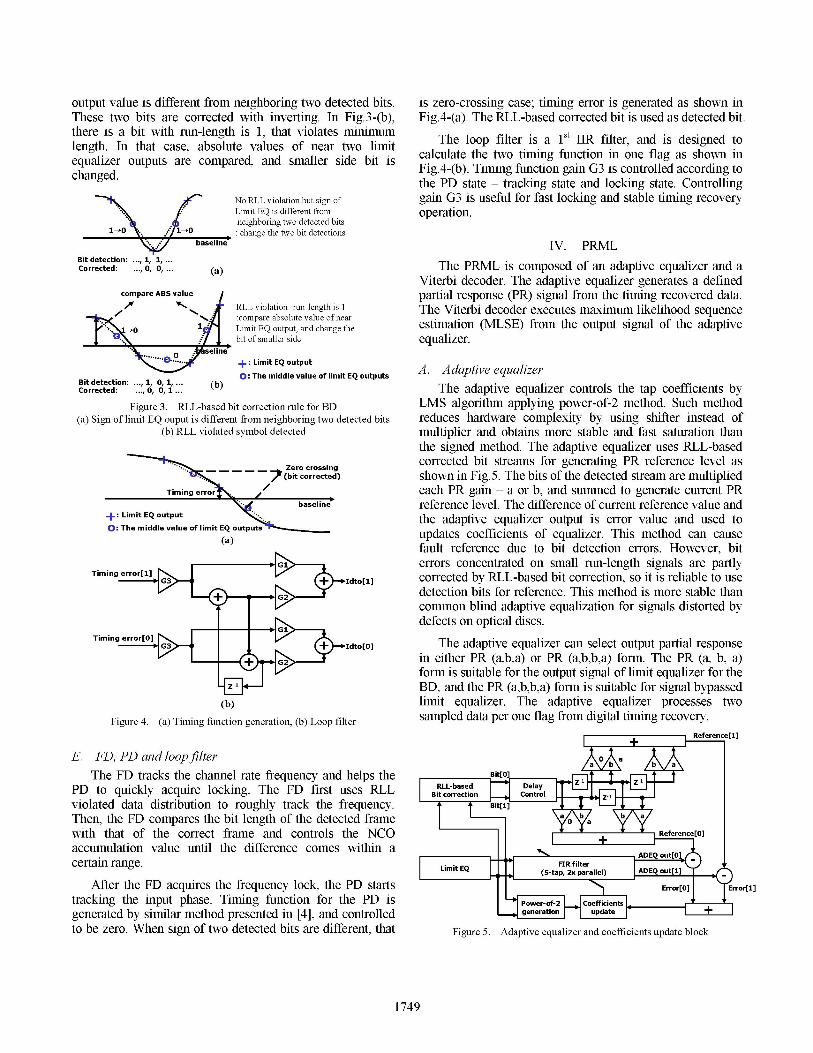
output value is different from neighboring two detected bits. is zero-crossing case; timing error is generated as shown inThese two bits are corrected with inverting. In Fig.3-(b), Fig.4-(a). The RLL-based corrected bit is used as detected bit.there is a bit with run-length is 1, that violates minimum The loop filter is a 1st IR filter, and is designed tolength. In that case, absolute values of near two limit Te the two 1S a 1 one ag aS shon inequalizer outputs are compared, and smaller side bit is calculate the two timig fiunction mi one flag as shown inchanged. Fig.4-(b). Timing function gain G3 iS controlled according tothe PD state - tracking state and locking state. Controlling
No RLL violation but sign of gain G3 is useful for fast locking and stable timing recoveryLimit EQ is different from operation.neighboring two detected bits
1-0 . . / 10:changethe two bit detectionsbaseline IV. PRML
Bit detection: 1, 1,Corrected: o, o, (a) The PRML is composed of an adaptive equalizer and a
Viterbi decoder. The adaptive equalizer generates a definedcompare ABS value partial response (PR) signal from the timing recovered data.
RLL violation- run-length is 1 The Viterbi decoder executes maximum likelihood sequence:icompare absolute value of near frmtesgaofhedpivL 0 1 Limit EQ output, and change the estimation (MLSE) from the output signal of the adaptive
l . 1\... / ,bit of smaller side equalizer.0 seline
+: Limit EQ output A. Adaptive equalizer0: The middle value of limit EQ outputsBitdetection: ,1, I...
(b) The adaptive equalizer controls the tap coefficients byFigure 3. RLL-based bit correction rule for BD LMS algorithm applying power-of-2 method. Such method
(a) Sign of limit EQ ouput is different from neighboring two detected bits reduces hardware complexity by using shifter instead of(b) RLL violated symbol detected multiplier and obtains more stable and fast saturation than
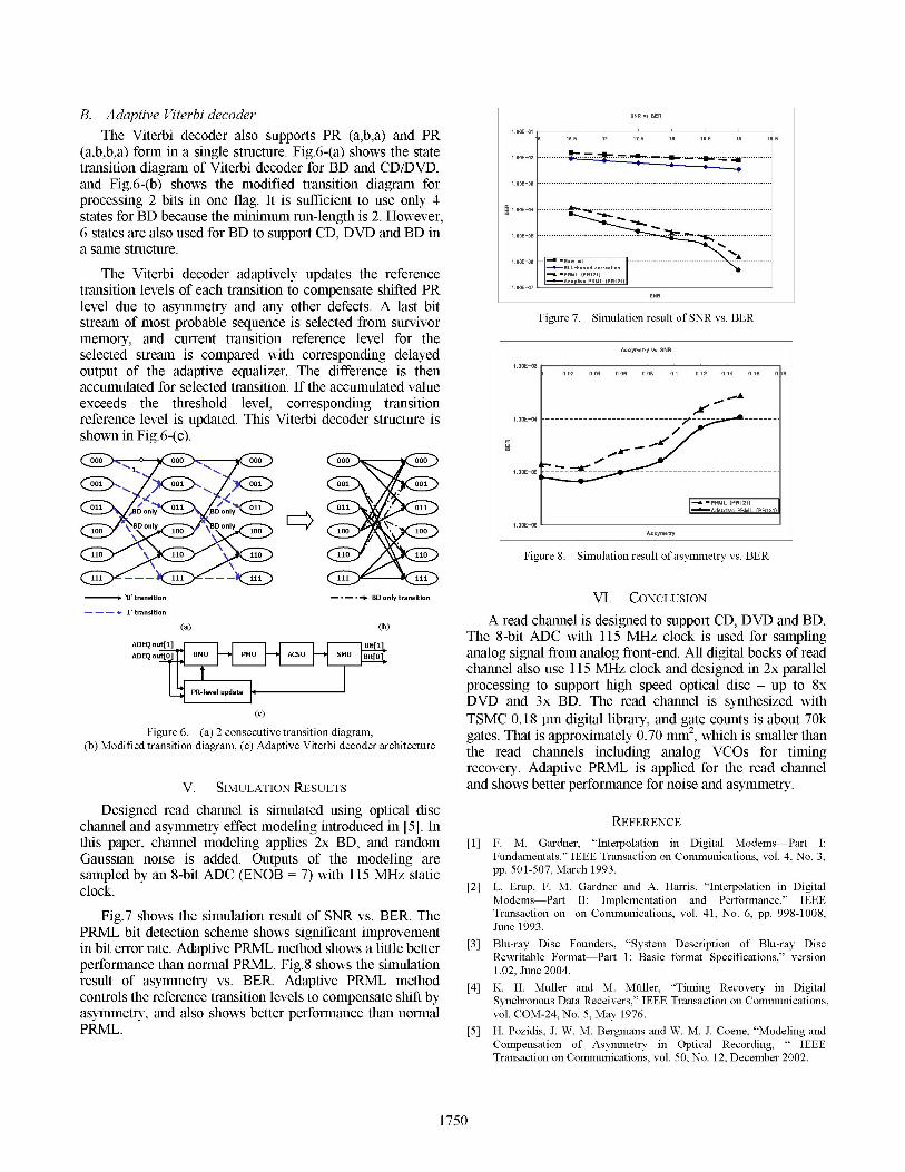
the signed method. The adaptive equalizer uses RLL-basedZero crossing corrected bit streams for generating PR reference level as
/ (bit corrected) shown in Fig.5. The bits of the detected stream are multipliedTiminge rro g/ each PR gain - a or b, and summed to generate current PR
*v;,( baseline' reference level. The difference of current reference value and+:Limit EQ output the adaptive equalizer output is error value and used to0: The middle value of limit EQ oupdates coefficients of equalizer. This method can cause
(a) fault reference due to bit detection errors. However, biterrors concentrated on small run-length signals are partlyTimingerror[l] G + Idto[1] corrected by RLL-based bit correction, so it is reliable to use
+ , detection bits for reference. This method is more stable thancommon blind adaptive equalization for signals distorted bydefects on optical discs.
Timing error[0] 1 Idto[O] The adaptive equalizer can select output partial responsein either PR (a,b,a) or PR (a,b,b,a) form. The PR (a, b, a)form is suitable for the output signal of limit equalizer for the
Z-1 BD, and the PR (a,b,b,a) form is suitable for signal bypassed(b) limit equalizer. The adaptive equalizer processes two
Figure 4. (a) Timing function generation, (b) Loop filter sampled data per one flag from digital timing recovery.+
Reference[1]
E. FD, PD and loopfilterThe FD tracks the channel rate frequency and helps the [° D
PD to quickly acquire locking. The FD first uses RLL RLL-based Delayviolated data distribution to roughly track the frequency. Bit[l] F
Then, the FD compares the bit length of the detected framewith that of the correct frame and controls the NCO + rence[0]accumulation value until the difference comes within a
A out[certain range. L
After the FD acquires the frequency lock, the PD starts > Error[0] Error[1]tracking the input phase. Timing function for the PD isl Poe-f2 Cficnt F, ,generated by similar method presented in [4], and controlled geeato upatto be zero. When sign of two detected bits are different, that Figure 5. Adaptive equalizer and coefficients update block
1749
B. Adaptive Viterbi decoder SB, E
The Viterbi decoder also supports PR (a,b,a) and PR 16 16OE 7 1O 8 18. 9 1f.(a,b,b,a) form in a single structure. Fig.6-(a) shows the state 1.OOE-02 -------- .............*..transition diagram of Viterbi decoder for BD and CD/DVD,
processing 2 bits in one flag. It is sufficient to use only 4states for BD because the minimum run-length is 2. However, 1OE6 states are also used for BD to support CD, DVD and BD in 1.E05.......a same structure.
The Viterbi decoder adaptively updates the reference -l PBML PWll21transition levels of each transition to compensate shifted PR 1.OOE-07
level due to asymmetry and any other defects. A last bitFgr .Smlto euto N E
stream of most probable sequence is selected from survivor Fgr .Smlto euto N s Ememory, and current transition reference level for theselected stream is compared with corresponding delayed Assymetry______vs ___SNR_output of the adaptive equalizer. The difference is then 0.02 0.04 OA6.8 0.12 0.14 O.16 0. 8accumulated for selected transition. If the accumulated valueexceeds the threshold level, corresponding transitionreference level is updated. This Viterbi decoder structure is1.E04------------------------------shown in Fig.6-(c).
000 0 0000 00
1. 00~~~~~~~~~~~~~~~~~~~~~~~~~~~~~~~~~~~~~~~~~~1OE~-05A"--
,BD only BD only 011- da2ii EM EIJ
10 BD oly 10IBony 0010 OE~-06/ ~~~~~~~~~~~~~~~~~ ~~~~~Asyer
110110 110~~~~~~~~C Figure 8. Simulation result of asymmetry vs. BER
------ '0' transition -- -* BD only transition VI.~ CONCLUSION
(a)' rnsto
b)A read channel is designed to support CD, DVD and BD.(a) (b) ~~~~~~~The8-bit ADC with 115 MHz clock is used for samplingADEQ out[lJ Bit[1Jaao frmfnted 1LuADEQ out[0J BMU PMU ACSU SUBit0 anlo sgnl ro analog frn-n.All diia bocks of read
channel also use 115 MHz clock and designed in 2x parallelPR-level update ~~~processing to support high speed optical disc - up to 8xPR-level update ~~DVD and 3x BD. The read channel is synthesized with(c) TSMC 0.18 lim digital library, anid gate counts is about 70k
Figure 6. (a) 2 consecutive transition diagram, gates. That is approximately 0.70 MM2, which is smaller than(b) Modified transition diagram, (c) Adaptive Viterbi decoder architecture the read channels including analog VCOs for timing
recovery. Adaptive PRM\L is applied for the read channelV. SimuLATioN RESUJLTS and shows better performance for noise and asymmetry.
Designed read channel is simulated using optical discRERNCchannel and asymmetry effect modeling introduced in [5]. hriRFENCthis paper, channel modeling applies 2x BD, and random [1] F. M. Gardner, "Interpolation in Digital Modems-Part I:Gaussian noise is added. Outputs of the modeling are Fundamentals," IEEE Transaction on Communications, vol. 4, No. 3,sampled by an 8-bit ADC (ENOB =7) with 115 MHz static pp. 501-507, March 1993.clock. [2] L. Erup, F. M. Gardner and A. Harris, "Interpolation in Digital
Modems-Part II: Implementation and Performance," IEEEFig.7 shows the simulation result of SNR vs. BER. The Transaction on on Communications, vol. 41, No. 6, pp. 998-1008,
PRM\L bit detection scheme shows significant improvement June 1993.in bit error rate. Adaptive PRM\L method shows a little better [3] Blu-ray Disc Founders, "System Description of Blu-ray Disc
perfonance hannomal PML. Fi. 8 sows th simuationRewritable Format-Part 1: Basic format Specifications,' version
result of asymmetry vs. BER. Adaptive PRM\L method [4 1.0H. Mulleran2.M0lr0"iig4eoer nDiiacontrols the reference transition levels to compensate shift by Synchronous Data Receivers," IEEE4- Transactionon4A4iIICommunications,";fa