robust one-to-one sweeping with harmonic s t …imr.sandia.gov/papers/imr22/imr22_1_cai.pdfrobust...
TRANSCRIPT
Robust One-to-One Sweeping withHarmonic S-T Mappings and Cages
Shengyong Cai1 and Timothy J. Tautges2
1 University of Wisconsin-Madison, Madison, WI 53706, [email protected]
2 MCS, Argonne National Laboratory, Madison, WI 53706, [email protected]
Abstract. A sweeping algorithm can generate hexahedral meshes by sweep-ing an all-quad mesh on the source surface to the target surface. For one-to-one sweeping, the most difficult thing is to generate an all-quad mesh on thetarget surface which has the same mesh connectivity as that of the sourcesurface. The traditional method is to use the affine transformation, like trans-lation, rotation, scaling or combinations of them. This method works very wellon the convex cases, while it fails for concave and multiply-connected surfaces.In this paper, harmonic function is used to map meshes from a source surfaceto its target surface. The result shows that it can generate an all-quad meshon the target surface with good quality without any inverted elements andthus avoid expensive smoothing algorithm (untangling). In order to generateinterior nodes between the source and target surface, cage-based deformationmethod is applied with good mesh quality as well.
Keywords: Harmonic, Sweeping, Hexahdral, Mesh Generation, One-to-One.
1 Introduction
In many applications such as Computational Fluid Dynamics (CFD) [1] andComputational Structural Mechanics (CSM ) [2], a hexahedral mesh is pre-ferred over a tetrahedral mesh. According to Ref. [3], there are two classesof methods for generating all-hexahedral meshes, namely, indirect methodswhich convert from a tetrahedral mesh to a hexahedral mesh [4], and di-rect methods. This latter may be further classified as Grid-based [5], MedialSurface [6, 7], Plastering [8], Whisker Weaving [9] and Sweeping [10]. Be-cause it is difficult to combine or divide tetrahedral elements in such a wayto guarantee the formation of all-hexahedra, the indirect methods are nei-ther reasonable nor tractable for mesh generation [3]. For the Grid-basedmethods, mesh quality at the boundary of a volume is very poor and inte-rior hex elements are not aligned with boundary hex elements (this is not
J. Sarrate & M. Staten (eds.), Proceedings of the 22nd 1International Meshing Roundtable,DOI: 10.1007/978-3-319-02335-9_1, © Springer International Publishing Switzerland 2013
2 S. Cai and T.J. Tautges
good for CFD). The Medial Surface method generates a hexahedral meshby decomposing volumes, which is an extension of Medial Axis method. Thedecomposed volumes are usually meshed with midside subdivision. However,this only works for geometry with 3-valent corner vertices, and less reliablyfor general geometry. Plastering is a 3D extension of the paving algorithm,and the Whisker Weaving method builds the dual of hexahedral meshes firstthen embeds meshes in 3D. Neither Plastering nor Whisker Weaving hasbeen shown to be robust for general 3D models.
While all-hexahedral mesh generation on general three dimensional geome-tries remains an elusive goal, algorithms to mesh two-and-one-half dimen-sional geometries, generally referred to as sweeping or projection methods,continue to be important [10, 11, 12, 13]. In real-world applications, many ge-ometry models can be constructed by sweeping in CAD software (Pro/E, UG,Solidworks, etc.) and subsequently hex-meshed using sweeping. More compli-cated models can often be decomposed into 2.5D pieces which are individuallysweepable. Therefore, in practice, geometric decomposition followed by sweep-meshing remains the workhorse approach for generating hexahedral meshes.
The traditional one-to-one sweeping procedure for all-hexahedral meshesconsists of four steps: (1) generate an all-quad mesh on a source surface;(2) project an all-quad mesh from a source surface to its target surface; (3)generate the structured all-quadrilateral meshes on the linking surface(s);(4) generate the hexahedral meshes, including interior nodes and elements,for volumes. The source and target surface may have different shapes, areasand/or curvatures, but they must be topologically equivalent homeomorphic.Of the above four steps, the two most difficult steps are to morph a sourcemesh to its target surface and locate interior nodes between them. This isespecially true for volumes with concave features and non-simply connectedsource/target surfaces.
In this paper, we describe a mesh morphing method that uses the har-monic function to generate meshes on the target surface with adequate meshquality, and a cage-based method for locating interior nodes that also achievesimproved mesh quality. In combination, these methods are used to generategood-quality hexahedral meshes using sweeping for which previous sweepingmethods fail. The remainder of this paper is structured as follows: Part 2summarizes recent works about one-to-one sweeping and surface mesh mor-phing. Then harmonic mapping is introduced and surface correspondenceestablishment is described as well in Part 3. Finally, a cage-based methodis applied in order to locate interior nodes between the source and targetsurface.
2 Previous Work
P. Knupp [10] devised two algorithms to locate interior nodes during sweep-ing: linear transformations between the bounding node loops and smoothing.
Robust One-to-One Sweeping with Harmonic S -T Mappings and Cages 3
In his approach, a source surface was given, consisting of a layer of meshelements with one or more bounding loops of vertices, along with a targetsurface with bounding loop(s), and a linear transformation was establishedbetween two surfaces. In order to avoid a singular transformation matrix, aset of point vectors on the bounding loops was redefined: xi′
s = xis−(2xc
s−xct)
(new positions of source nodes are redefined as their physical positions - twotimes source affine center + target affine center); xi′
t = xit − xc
s (new posi-tions of target nodes are redefined as their physical positions - source affinecenter). Linear transformations for successive loops were computed using anadvancing front method based on consecutive boundary loops derived fromthe linking surfaces. After locating interior nodes and connecting points withthe same quadrilateral mesh connectivity as the source surface, this layer wassmoothed independently of connections to nodes on the neighboring layers.However, this approach fails for moderately concave or multiply-connectedsource/target surfaces, and often does not produce smooth transitions be-tween highly-curved source/target surfaces.
X. Roca et al. [12] used the least-squares approximation of an affine map-ping for projecting a source surface mesh onto its target surface. The mappingwas defined between the parametric spaces on the source and target surface,using only boundary nodes. In order to avoid the skewn and flattening effectswhen locating interior nodes on the target surface, several functions with theleast-squares forms [13] were introduced to perform the least-squares approx-imation. However, this approach still suffers from poor mesh quality on thetarget surface which is concave and/or multiply-connected. In addition, thismethod could not be used for the source/target surfaces with no parame-terization, which sometimes arises when meshing a discrete (i.e. facet-based)geometry.
The BoundaryError method [14, 15] was introduced to place nodes using alinear affine algorithm and a subsequent residual error correction. In order tosuccessfully capture curvatures of source and target surface, the BoundaryEr-ror method calculated the residual error twice, which was then interpolatedfor final interior node location. This method is useful for locating interiornodes inside a volume between the source and target surface but not suitablefor mapping a source surface mesh onto its target surface.
M. L. Staten et al. [11] developed an algorithm called BMSweep to placeinterior nodes on the target surface and those between the source and targetsurface. The background mesh, which was generated by tessellating boundarynodes on the source surface in the parametric space, was needed to providea framework for computing interior nodes locations on each layer. However,if there is a volume with distorted holes and the same background meshconnectivity is used for all the layers during sweeping, inverted elements willbe introduced in the background mesh.
M. L. Staten and S. J. Owen et al. [16] also described six mesh mor-phing techniques for 3D shape optimization: smoothing, weighted residuals(BoundaryError), simplex-linear transformation (BMSweep), simplex-natural
4 S. Cai and T.J. Tautges
neighbor transformation, finite element and Log Barrier method. The simplex-linear transformation and finite element Warping were recommended for amesh morphing system. However, simplex-linear transformation based onBMSweep suffers from the same drawbacks as BMSweep. The finite element-based mesh warping algorithm expresses coordinates of each interior node asan affine combination of its neighbors with shape functions encapsulated inthe element stiffness matrix for each element. It is very expensive to solvethe stress equilibrium equations.
S. M. Shontz et al. [17] presented a mesh warping algorithm for tetrahe-dral meshes based on weighted Laplacian smoothing. A set of local weightsfor each interior node, which described relative distances of a node to itsneighbors, was determined. After deforming boundaries, a system of linearequations based on weights was solved to determine final locations of interiornodes. However, it is an extension of smoothing and only works for morphingsurfaces with smaller deformation.
R. Vurputoor et al. [18] proposed a mesh morphing technique for geomet-rically dissimilar tessellated surfaces. A topologically conforming backgroundtemplate mesh on the target surface was created by using the same trianglemesh connectivity as the source surface. Hence, those background mesheswere used to map interior nodes between the source and target surface. How-ever, due to the same triangle mesh connectivity used on the source andtarget surface, inverted elements may be introduced in the background meshon the target surface if there is a surface with twisted holes and constantoutmost boundary.
I. Sigal et al. [19] presented two morphing algorithms, namely, automatedwrapping and manual landmarks, and applied them to prepare specimen-specific models of caudal rat vertebrae. The basic idea of automated wrap-ping was to find mappings from the source and target surfaces to an auxiliarysurface instead of finding a mapping between the complicate source and tar-get surfaces. However, this kind of mesh morphing works very well only forclosed surfaces and volume morphing, while the source and target surfacesare generally open during sweeping.
One problem in morphing from one shape to another is to establish the cor-respondence map [20]. Fortunately, many scholars have solved this problemfrom their perspectives. T. Kanai et al. [21] used harmonic maps for morph-ing triangle meshes with any arbitrary topology. The basic idea was to de-fine reference shapes by using vertex-to-vertex correspondences between twomeshes. The partition of a mesh was defined by the reference shape and par-titioned meshes were embedded into a polygonal region in the plane throughharmonic maps. By overlapping two embedded meshes, the correspondencewas established between them. A. Lee et al. [20] presented a method for user-controlled morphing of two homeomorphic triangle meshes of any arbitrarytopology. The MAPS algorithm (Multiresolution Adaptive Parameterizationof Surfaces [22]) was employed to parameterize both meshes over simple base
Robust One-to-One Sweeping with Harmonic S -T Mappings and Cages 5
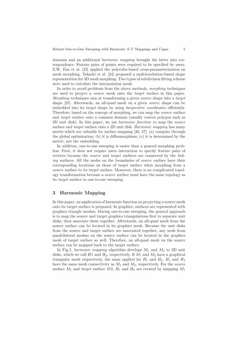
domains and an additional harmonic mapping brought the latter into cor-respondence. Feature pairs of points were required to be specified by users.Z.W. Fan et al. [23] applied the polycube-based cross-parameterization onmesh morphing. Takashi et al. [24] proposed a multiresolution-based shaperepresentation for 3D mesh morphing. Two types of subdivision fitting schemewere used to calculate the interpolation mesh.
In order to avoid problems from the above methods, morphing techniquesare used to project a source mesh onto the target surface in this paper.Morphing techniques aim at transforming a given source shape into a targetshape [25]. Afterwards, an all-quad mesh on a given source shape can beembedded into its target shape by using barycentric coordinates efficiently.Therefore, based on the concept of morphing, we can map the source surfaceand target surface onto a common domain (usually convex polygon such as2D unit disk). In this paper, we use harmonic function to map the sourcesurface and target surface onto a 2D unit disk. Harmonic mapping has manymerits which are valuable for surface mapping [26, 27]: (a) compute throughthe global optimization; (b) it is diffeomorphism; (c) it is determined by themetric, not the embedding.
In addition, one-to-one sweeping is easier than a general morphing prob-lem. First, it does not require users interaction to specify feature pairs ofvertices because the source and target surfaces are connected by the link-ing surfaces. All the nodes on the boundaries of source surface have theircorresponding locations on those of target surface when morphing from asource surface to its target surface. Moreover, there is no complicated topol-ogy transformation because a source surface must have the same topology asits target surface in one-to-one sweeping.
3 Harmonic Mapping
In this paper, an application of harmonic function on projecting a source meshonto its target surface is proposed. In graphics, surfaces are represented withgraphics triangle meshes. During one-to-one sweeping, the general approachis to map the source and target graphics triangulations first to separate unitdisks, then associate them together. Afterwards, an all-quad mesh from thesource surface can be located in its graphics mesh. Because the unit disksfrom the source and target surface are associated together, any node fromquadrilateral meshes on the source surface can be located in the graphicsmesh of target surface as well. Therefore, an all-quad mesh on the sourcesurface can be mapped back to the target surface.
In Fig.1, harmonic mapping algorithm develops M1 and M2 to 2D unitdisks, which we call H1 and H2, respectively. If M1 and M2 have a graphicaltriangular mesh respectively, the same applied for H1 and H2. H1 and H2
have the same mesh connectivity as M1 and M2, respectively. For the sourcesurface M1 and target surface M2, H1 and H2 are created by mapping M1

6 S. Cai and T.J. Tautges
and M2 onto 2D unit disk by using the harmonic mapping, respectively. Inorder to establish the correspondence betweenH1 and H2, a new common 2Dunit disk Hc (which is replaced by H2 later) needs to be created by adjustingnodes location on boundaries and combining both H1 and H2. Recall thatHc has both M1 and M2s connectivity. For the sake of simplicity, we keep 2Dunit disk H2 fixed. Without creating a new Hc and mapping from H1 to Hc,the boundary nodes on H1 are adjusted in order to make the boundary nodesbetween H1 and H2 correspond. After the boundary correspondence betweenH1 and H2 is made, 2D unit disk H1 is mapped onto H2 directly. Then thecorrespondence between M1 and M2 is established. Afterwards, an all-quadmesh on the source surface can be mapped back to the target surface. Inorder to guarantee that the harmonic mapping is one-to-one and well definedfor geometries with large aspect ratios, the graphical triangular mesh may besmoothed on the geometry if possible before harmonic mapping.
Fig. 1 Road map for mapping an all-quad mesh from a source surface to its targetsurface. (1) M1 is mapped onto H1. (2) M2 is mapped onto H2. (3) The boundarynodes of H1 are adjusted and correspondence between H1 and H2 is made. H1 ismapped onto H2. (4) Quadrilateral meshes on the source surface are mapped backonto M2.
3.1 Harmonic Mapping
Harmonic Map ϕ, M → H is mapping between two Riemannian manifolds.M and H are harmonic if the Dirichlet energy is minimized. Harmonic Mapperforms a mapping from a topological disk to a 2D unit disk. To construct

Robust One-to-One Sweeping with Harmonic S -T Mappings and Cages 7
the source and target surfaces embeddings, the piecewise linear approxima-tion method for mapping from M to H is used [21,28], which is established asfollows: n vertices on the outmost boundary are distributed on the boundaryof 2D disk. This could be based on the edge length between two adjacentboundary nodes. After vertices on the outmost boundary of source surfacehave been distributed, vertices on the outmost boundary of target surfaceshould be fixed as well because they are corresponded with those of sourcesurface and located through the linking surfaces. For a multiply-connectedsurface, the mapping remains one-to-one even when considering holes in thedomain [29]. Based on the Ref. [30], if there is a genus zero surface S withmultiple boundaries, and a Riemannian metric g, then there exists a confor-mal map f : S → D, where D is a 2D unit disk with circular holes.
3.1.1 Discrete Harmonic 1-Form
Let [vi, vj ] be an interior edge on the triangular mesh, connecting two faces
[vi, vj , vk] and [vi, vj , vl], the corner angle in [vi, vj , vk] against [vi, vj ] is θijk ,
the corner angle in [vi, vj , vl] against [vi, vj ] is θijl , the edge weight is defined
asωij = cotθijk + cotθijl (1)
The discrete harmonic energy is defined as
E(f) =∑
[vi,vj ]
ωij(f(vi)− f(vj))2 (2)
The discrete harmonic function is the critical point of the harmonic energy,which satisfies the following discrete harmonic 1-form.
δf(vi) =∑
[vi,vj ]∈E
ωij(f(vi)− f(vj)) = 0, ∀vi ∈ V (3)
Where V is a set of all the vertices.
3.1.2 Multiply Connected Domains
If a function is harmonic (that means it satisfies Laplace’ equation over aparticular space) and transformed via a conformal map to another space, thetransformation is also harmonic. If there is a genus zero surface with multi-ple holes, the generalized Koebe’s method could be applied to compute thecanonical conformal mappings [30] where the harmonic mapping is a par-ticular conformal mapping. The conformal mapping of a multiply connecteddomain is equivalent to compute the conformal mapping of a topologicalannulus, which is reduced to compute a pair of conjugated harmonic 1-forms.
Suppose there is a surface S with n holes γi, i = 1, · · · , n and boundariesDi, i = 1, · · · , n. The outmost boundary which bounds the surface S can be

8 S. Cai and T.J. Tautges
Fig. 2 An example of conformal mapping of S to the canonical annulus (γ0 → c0,γ1 → c1)
denoted as ∂S0. The conformal mapping could be computed in the followingsteps [30].
(1) Remove a hole Dk from a surface S by computing a path which connectsDk and ∂S0. Then the boundary of a hole becomes a part of ∂S0. All otherholes are filled by connecting the hole mass center with the boundaryvertices on each individual hole. An example is shown in Fig. 2.
(2) Conformally map the surface S (annulus) to the canonical annulus, suchthat the boundary (Dk) of γk is mapped to a circle ck.
ϕk : S −Dk → unit disk
such that ϕk(γk) = ck(3) Compute a harmonic mapping of Dk, with the boundary condition that
the boundary of Dk is mapped to ck.
fk : Dk → a disk inside 2D unit disk, Δfk = 0, fk|γk= ck
(4) Update the whole mesh S
S ← ϕk(S −Dk) ∪ fk(Dk)
(5) Process the remaining holesDi(i = 1, · · · , n) individually using the abovesteps. Then the boundary of each disk is mapped to a circular curve,compute the center and radii as (ck,rk).
(6) Repeat step 5 until it converges.
3∑k=1
|c0k − c1k|2 + |r0k − r1k|2 < ε
where (c0k,r0k) and (c1k,r
1k) are the center and radius of Di of two consec-
utive iterations.

Robust One-to-One Sweeping with Harmonic S -T Mappings and Cages 9
3.2 Establish Surface Correspondence
In the Sec. 3.1, an embedding H1 or H2 has already been created from M1 orM2. In this section, two embeddings are associated together (H2 is fixed andkept constant), which has the combined mesh connectivity from both sourcesurface M1 and target surface M2. After establishing the correspondencebetween H1 and H2, any point from the source surface M1 corresponds witha position on the target surface M2.
An all-quad mesh generation on the target surface mapped from a sourcesurface mesh consists of four steps.
(1) Based on Sect. 3.1.2, map the target surface M2 onto a 2D unit disk H2.(2) Perform a mapping from the source surface M1 onto 2D unit disk H1 and
H2: first, adjust vertices on the boundaries in H1 so that those on H1 aremoved to their corresponding positions on H2 (corresponding positionscan be obtained from the linking sides between M1 and M2). Recall thatM1 and M2 may have different triangle mesh nodes and connectivity,it is not necessary to make all the vertices on the outmost boundaryoverlap. However, they should be corresponded. In other words, thosevertices on the boundaries of H1 are fixed once H2 is fixed because thelinking surfaces guide the correspondence between M1 and M2. Then theharmonic mapping is performed and M1 and M2 are mapped onto H2.
(3) Compute the barycentric coordinates for every mesh node from thequadrilateral meshes on the source surface through the graphical tri-angular mesh M1. Then calculate 2D positions of every mesh node fromthe quadrilateral meshes of source surface M1 at H1 by using the samebarycentric coordinates. In this step, every node from the quadrilateralmeshes of source surface on the graphical triangle mesh M1 could beplaced on H1. Because there is an all-quad mesh on the source surfaceM1, a triangular face is searched at H1 on the source surface where eachmesh node n1
m is located (See Fig. 3(a)). When n1m is located in a face
{v1i ,v1j ,v1k} of H1, the barycentric coordinates (i11,i12,i
13) can be computed
as follows.
Fig. 3 Mapping vertex n1m in H1 to H2
10 S. Cai and T.J. Tautges
n1m = i11v
1i + i12v
1j + i13v
1k (4)
i11 + i12 + i13 = 1 (5)
Where n1m is a mesh node on the source surface and v1i ,v
1j and v1k are
three vertices of a triangle from the graphical triangulations.(4) Calculate corresponding 3D positions on the target surface M2 of each
mesh node n2m at H2. Search a triangular face at H2 where a node n1
m
in H1 is included in order to compute 3D locations of a node n2m on
the target surface M2 (see Fig. 3(b)). When n1m is located in a triangu-
lar face {v2i ,v2j ,v2k} at H2, the barycentric coordinates (i21,i22,i
23) could be
computed as follows.
n2m = i21v
2i + i22v
2j + i23v
2k (6)
i21 + i22 + i23 = 1 (7)
Where n2m is a mesh node on the target surface. 3D position on the
target surface for a mesh node n2m is computed based on the barycentric
coordinate on the face (i21, i22, i
23).
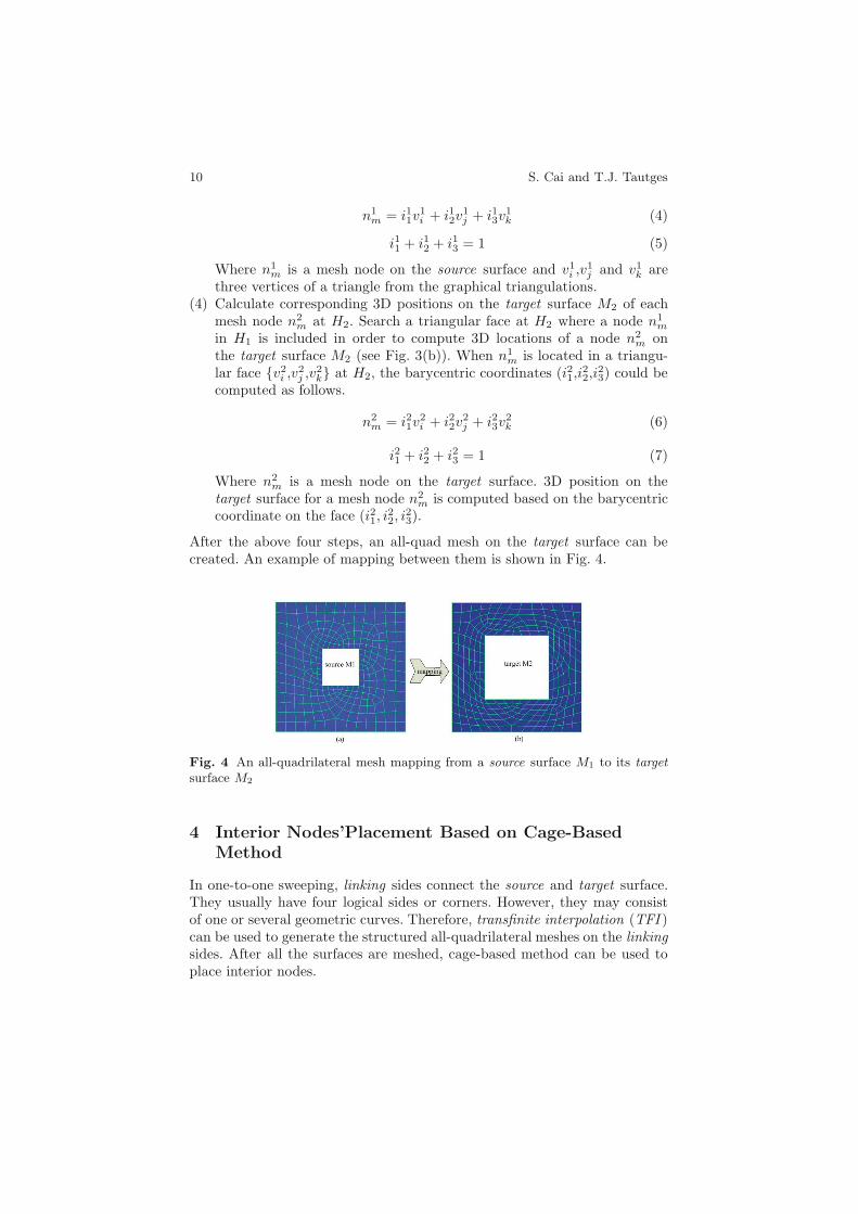
After the above four steps, an all-quad mesh on the target surface can becreated. An example of mapping between them is shown in Fig. 4.
Fig. 4 An all-quadrilateral mesh mapping from a source surface M1 to its targetsurface M2
4 Interior Nodes’Placement Based on Cage-BasedMethod
In one-to-one sweeping, linking sides connect the source and target surface.They usually have four logical sides or corners. However, they may consistof one or several geometric curves. Therefore, transfinite interpolation (TFI )can be used to generate the structured all-quadrilateral meshes on the linkingsides. After all the surfaces are meshed, cage-based method can be used toplace interior nodes.

Robust One-to-One Sweeping with Harmonic S -T Mappings and Cages 11
4.1 Introduction
The cage-based deformation allows an arbitrary closed mesh to act as a de-formation cage around another mesh. Figure 5 is an example of deformedobject (gray color) inside a deformed mesh cage (black wireframe). There isonly one requirement for a cage that the deformed mesh cage could be anyshape of mesh but it must be closed. In Fig. 5, the cage has been altered usingproportional editing, as a result the sphere alters its shape in response. Theobject (gray color) is bound with its cage mesh. When the cage mesh is de-formed, the object is told to use the deformed cage to deform itself. Basically,
Fig. 5 A 3D example of deformed sphere when its enclosing cage is deformed
there are four steps for a cage-based deformation: (1) automatically or man-ually create a cage to enclose an object to be deformed; (2) bind an objectwith its cage (cage vertices). In this step, the geometry info of an enclosedobject is bound with its cage vertices. That means every vertex on an objectis a function of its cage vertices. If any cage vertex is altered, the object willdeform itself by using its deformed cage. (3) deform a cage in order to deforman object; (4) interpolate new object in response to the deformed cage. In theabove four steps, step (2) is the most difficult one. Current approaches forstep (2) include Mean Value Coordinates, Harmonic Coordinates and GreenCoordinates. Current cage methods express a point η inside a cage P as anaffine sum of its cage vertices V = {vi}i∈IV ⊂ R3. Let i be the cage vertexindex, vi be 3D location of a cage vertex i and IV be a set of cage vertices,then we have

12 S. Cai and T.J. Tautges
η = F (η;P ) =∑
i∈IV
φi(η)vi (8)
Where φi(η) is the weight for representing the deformation influence andoften referred as ”coordinates”. Then the deformation defined by a deformedcage P ′ is defined by
η = F (η;P ′) =∑
i∈IV
φi(η)v′i (9)
4.2 Framework for Locating Interior Nodes
During one-to-one sweeping, the cage-based deformation can be applied toplace interior nodes inside volumes because interior nodes are enclosed bytheir bounding surfaces (source, target and linking surfaces). An exampleis shown in Fig. 6 with all the bounding surfaces as a deformed cage. Ourmethods proceed using the following steps:
Fig. 6 The physical and topological model for locating interior nodes inside avolume: (a)a physical model; (b)meshed bounding surfaces for(a); (c)a topologicalmodel from (a); (d)hexahedral meshes generated for (c).
(1) Create the Topological Model: start from a target surface and trans-late its quadrilateral meshes in the inverse sweeping direction until itssource surface is reached.
(2) Mesh Conversion: convert quadrilateral meshes on the bounding sur-faces into triangular meshes both in the physical model and topologicalmodel. All these triangular meshes (from the physical model and topo-logical model) should have the same mesh connectivity in both physicalmodel and topological model and they correspond each other.
(3) Binding: in the topological model, positions of interior nodes have al-ready been placed by simple translation (see Fig. 6(d)). Because all thevertices on the bounding surfaces in the topological model have alreadybeen located as well, the cage-based deformation techniques could be

Robust One-to-One Sweeping with Harmonic S -T Mappings and Cages 13
used to bind interior nodes with respect to their cage vertices on thebounding surfaces in the topological model. That means: every interiornode location is a function of its cage vertices on the bounding surfaces.
(4) Interpolation: the triangle meshes converted from quad meshes on thebounding surfaces in physical model are used as a deformed cage. Becausethe binding process is done in step 3, Eqn. 8 with a deformed cage asinputs could be used to interpolate final location of interior nodes insidethe deformed cage.
4.3 Harmonic Coordinates
The main problem to solve the desired cage-object relationship (binding pro-cess in Sect. 4.2) starts with a theoretical problem. Let a cage C be a poly-hedron in d dimensions (it is a closed planar polygon in 2D and a closedregion bound by planar faces in 3D). For each cage vertex Ci, a functionhi(p) (harmonic coordinates) defined on the cage C should satisfy the fol-lowing conditions (p is an interior node inside its cage) [31]: (1) interpolationhi(Cj)=δ(i, j); (2)hi(p) should have at least C1 smooth inside a cage; (3)non-negativity hi(p) ≥ 0, for all the interior points p ∈ C; (4)interior lo-cality: interior locality holds, if, in addition to non-negativity, the coordinatefunctions have no interior extrema; (5) linear reproduction Given an arbitraryfunction f(p), it should satisfy H [f ](p)=
∑i hi(p)f(Ci); (6)affine invariance∑
i hi(p)=1 for all the interior points p ∈ C; (7) strict generalization ofbarycentric coordinates hi(p) is a barycentric coordinate of p with respectto a cage vertex Ci. The coordinate functions satisfying all seven propertiescould be solutions to the Laplaces equation.
2 hi(p) = 0, p ∈ Interior(C) (10)
Let ∂p denotes a point on the boundary of ∂C of C. Then
hi(∂p) = φi(∂p) for all ∂p ∈ ∂C (11)
Where φi(∂p) is the (univariate) piecewise linear function such that φi(Cj)= δi,j .
The approximation of harmonic functions by piecewise linear functionsover triangulations on the bounding surfaces (used as the cage), in such away that the injective property is preserved. Harmonic Coordinates could becomputed as follows [31]:
(1) Allocate a regular grid which is large enough to enclose the whole cage.Each grid cell contains a value and a tag. A tag could be one of UN-TYPED, BOUNDARY, INTERIOR, or EXTERIOR.
(2) Initialize the grid by marking all the cells as UNTYPED.(3) Scan-convert boundary conditions into the grid, marking each scan con-
verted cell with the BOUNDARY tag. In 3D, it is restricted to triangular

14 S. Cai and T.J. Tautges
faces, meaning that the boundary values varying in a piecewise linear fash-ion. The BOUNDARY cells could be marked with harmonic coordinatevalue equal to 1.
(4) Start with one of corner cells, flood fill the exterior, mark each visitedcells with EXTERIOR tag. It stops when BOUNDARY cells are reached.During this step, only the exterior cells are visited in that boundingsurfaces are closed.
(5) Mark the remaining UNTYPED cells as INTERIOR with harmonic co-ordinate value equal to 0.
(6) Laplacian Smoothing: for each INTERIOR cell, replace cells value withan average of its neighbors.
5 Results
All the development and testing were done on Ubuntu 13.04, running on IntelCore-2 processors with 4GB RAM. In order to assess mesh quality of newsweeping algorithm based on harmonic mapping, several examples are pro-vided. The new sweeping algorithm works for the geometry: cap surfaces withdifferent shapes and curvature, but with the same topology. For the geome-try with non-constant cross section along the sweeping direction, nonlinearsweeping trajectories, non-parallel cap surfaces or non-simply connected capsurfaces, it works as well. The new sweeping algorithm based on harmonicmapping can avoid inverted elements and produce good-quality meshes whenan all-quadrilateral mesh is mapped onto the target surface. After all thebounding surfaces are meshed, the cage-based deformation method is usedto place interior nodes inside volumes in order to deal with the complicatedinternal structures inside volumes. The results show the hexahedral mesheswith good quality are produced as well.
The first example in Fig. 7 is a blocky volume where there is an increas-ing hole between the source and target surface. The interior boundary israndomly curved. A simple linear affine transformation will produce 170 in-verted elements when a source mesh is swept towards the target surface. Afterthe surface mesh projection based on harmonic mapping is used, inverted el-ements could be eliminated (see Fig. 7(d) for details). However, Cubit13.2generates some inverted elements shown in Fig. 7(c) when an all-quad meshon the source surface is swept towards the target surface. For comparison,the mesh quality histograms from our method and Cubit13.2 are plotted inFig. 7(e) and Fig. 7(f). The result shows that an all-hex mesh produced byour method has better mesh quality.
Figure 8 shows a blocky volume with a concave feature and an increasingtwisted hole between the source and target surface. An all-quad mesh on thesource surface is shown in Fig. 8(b). After our method is applied, an all-quadmesh on the target surface without any inverted element is produced in Fig.8(d). For comparison, this example is run on Cubit13.2 and mesh quality

Robust One-to-One Sweeping with Harmonic S -T Mappings and Cages 15
Fig. 7 Swept volume with a varying hole of random boundary. (a) a geometrymodel; (b) quadrilateral mesh on the source surface; (c) quadrilateral on the targetsurface generated by Cubit ; (d) quadrilateral mesh on the target surface generatedby our method; (e) a quality histogram from Cubit ; (f) a quality histogram fromour method.
Fig. 8 Volumes with concavities and increasing twisted hole. (a) a geometry model;(b) an all-quad mesh on the source surface; (c) an all-quad mesh generated by Cubit13.2 ; (d) an all-quad mesh on the target surface generated by our method; (e) aquality histogram from Cubit13.2 ; (f) a quality histogram from our method.
histograms from our method and Cubit13.2 are plotted in Fig. 8(f) and Fig.8(e). The results show that our method can produce all-hexahedral mesheswithout any inverted element and with better mesh quality.

16 S. Cai and T.J. Tautges
Fig. 9 A spongecake meshed with sweeping. (a) a geometry model; (b) quadri-lateral mesh on the source surface; (c) quadrilateral mesh on the target surfacegenerated by our method; (d) a quality histogram.
The third example in Fig. 9 is a spongecake which is similar to cylinder witha lot of varying holes inside the volume (increasing hole sizes and decreasinghole sizes between the source and target surface). The cap surfaces are curved.Simple linear affine transformation would create 709 inverted elements insideholes. After surface mesh projection based on harmonic mapping is used, noinverted elements are created. The final all-hexahedral meshes are shown inFig. 9(c). The mesh quality histogram in Fig. 9(d) shows that an all-hex meshproduced by our method has better mesh quality.
6 Conclusion
In this paper, a new algorithm to project an all-quad mesh on source sur-face to target surface based on harmonic mapping has been presented. It hasbeen successfully implemented in MeshKit [35]. The projection between twotopologically equivalent surfaces is determined by making the correspondencebetween them based on harmonic mapping. First generate 2D unit disk basedon harmonic mapping. Then make the correspondence between two unit disks.Finally, an all-quad mesh on the source surface is mapped back to the tar-get surface. In order to locate interior nodes between the source and target

Robust One-to-One Sweeping with Harmonic S -T Mappings and Cages 17
surfaces, the cage-based method is used to produce good-quality hexahedralmeshes compared to Cubit13.2.
Acknowledgement. This work was funded under the auspices of the Nuclear En-ergy AdvancedModeling and Simulation (NEAMS) program of the Office of NuclearEnergy, and the Scientific Discovery through Advanced Computing (SciDAC) pro-gram funded by the Office of Science, Advanced Scientific Computing Research,both for the U.S. Department of Energy, under Contract DE-AC02-06CH11357.We also thank all the Fathom members (from both Univ. of Wisconsin-Madisonand Argonne National Lab) for their efforts on the CGM [32], MOAB [33], Lasso[34] and MeshKit [35] libraries, which were used heavily to support this work.
References
1. Biswas, R., Strawn, R.C.: Tetrahedral and hexahedral mesh adaptation forCFD problems. Applied Numerical Mathematics 26(1-2), 135–151 (1988)
2. Samareh, J.A.: Geometry and grid/mesh generation issues for CFD and CSMshape optimization. Optimization and Engineering 6(1), 21–32 (2005)
3. Owen, S.J.: A Survey of Unstructured Mesh Generation Technology. In: 7thIMR, pp. 239–267 (1998)
4. Taniguchi, T., Goda, T., Kasper, H., et al.: Hexahedral Mesh Generation ofComplex Composite Domain. In: 5th International Conference on Grid Gener-ation in Computational Field Simmulations, pp. 699–707 (1996)
5. Schneiders, R.: A Grid-based Algorithm for the Generation of Hexahedral El-ement Meshes. Engineering with Computers 12(3-4), 168–177 (1996)
6. Price, M.A., Armstrong, C.G.: Hexahedral Mesh Generation by Medial SurfaceSubdivision: Part I. IJNME 38(19), 3335–3359 (1995)
7. Price, M.A., Armstrong, C.G.: Hexahedral Mesh Generation by Medial SurfaceSubdivision: Part II. IJNME 40, 111–136 (1997)
8. Blacker, T.D., Myers, R.J.: Seams and Wedgers in Plastering: A 3D HexahedralMesh Generation Algorithm. Engineering With Computers 2, 83–93 (1993)
9. Tautges, T.J., Blacker, T.D., Mitchell, S.A.: The Whisker-Weaving Algorithm:A Connectivity Based Method for Constructing All-Hexahedral Finite ElementMeshes. IJNME 39, 3327–3349 (1996)
10. Patric, M.K.: Next-Generation Sweep Tool: A Method for Generating All-HexMeshes on Two-And-One-Half Dimensional Geometries. In: 7th IMR, pp. 505–513 (1998)
11. Staten, M.L., Canann, S.A., Owen, S.J.: BMSweep: Locating Interior NodesDuring Sweeping. In: 7th IMR, pp. 7–18 (1998)
12. Roca, X., Sarrate, J., Huerta, A.: Surface Mesh Projection for Hexahedral MeshGeneration by Sweeping. In: 13th IMR, pp. 169–180 (2004)
13. Roca, X., Sarrate, J., Huerta, A.: A new least-squares approximation of affinemappings for sweep algorithms. In: 14th IMR, pp. 433–448 (2005)
14. White, D.R., Lai, M.W., et al.: Automated Hexahedral Mesh Generation byVirtual Decomposition. In: 4th IMR, pp. 165–176 (1995)
15. Scott, M.A., Earp, M.N., Benzley, S.E., et al.: Adaptive Sweeping Techniques.In: 14th IMR, pp. 417–432 (2005)

18 S. Cai and T.J. Tautges
16. Staten, M.L., Owen, S.J., Shontz, S.M., Salinger, A.G., Coffey, T.S.: A com-parison of mesh morphing methods for 3D shape optimization. In: Quadros,W.R. (ed.) Proceedings of the 20th International Meshing Roundtable, vol. 90,pp. 293–311. Springer, Heidelberg (2011)
17. Shontz, S.M., Vavasis, S.A.: A mesh warping algorithm based on weightedLaplacian smoothing. In: 12th IMR, pp. 147–158 (2003)
18. Vurputoor, R.M., et al.: A Mesh Morphing Technique for Geometrically Dis-similar Tessellated Surfaces. In: 16th IMR, pp. 315–334 (2008)
19. Sigal, I.A., Hardisty, M.R., Whyne, C.M.: Mesh-morphing algorithms forspecimen-specific finite element modeling. Journal of Biomechanics 41(7), 1381–1389 (2008)
20. Lee, A., Dobkin, D., Sweldens, W., Schroder, P.: Multiresolution Mesh Morph-ing. In: Proceedings of SIGGRAPH 1999, pp. 343–350 (1999)
21. Kanai, T., Suzuki, H., Kimura, F.: Three-dimensional geometric metamorphosisbased on Harmonic Maps. The Visual Computer 14(4), 166–176 (1998)
22. Lee, A.W.F., Sweldens, W., Schroder, P., et al.: MAPS: Multiresolution Adap-tive Parameterization of Surfaces. In: SIGGRAPH 1998 Proceedings, pp. 95–104 (1998)
23. Fan, Z.W., Jin, X.G., Feng, J.Q.: Mesh Morphing using polycube-based cross-parameterization. Computer Animation and Virtual Worlds 16, 499–508 (2005)
24. Kanai, T., Fujita, M., Chiyokura, H.: Multiresolution interpolation meshes. In:9th Pacific Graphics International Conference, vol. 10, pp. 60–69 (2001)
25. Marc, A.: Recent Advances in Mesh Morphing. CG Forum, 1–23 (2002)26. Wang, Y., Gupa, M., Gu, X.F., et al.: High Resolution Tracking of non-Rigid 3D
Motion of Densely Sampled Data Using Harmonic Maps. In: IEEE InternationalConference on Computer Vision (2005)
27. Joshi, P., Meyer, M., et al.: Harmonic Coordinates for Character Articulation.ACM Transactions on Graphics 26(3(7)) (2007)
28. Zhang, D., Hebert, M.: Harmonic maps and their applications in surface match-ing. In: IEEE Conference on Computer Vision and Pattern Recognition (1999)
29. Remacle, J.F., Geuzaine, C., Compere, G., et al.: High Quality Surface Remesh-ing Using Harmonic Maps. IJNME 83(4), 403–425 (2009)
30. Zeng, W., Yin, X.T., Zhang, M., Luo, F., Gu, X.F.: Generalized Koebe’smethod for conformal mapping multiply connected domains. In: SIAM/ACMJoint Conference on Geometric and Physical Modeling, pp. 89–100. ACM(2009)
31. Joshi, P., Meyer, M., DeRose, T., et al.: Harmonic coordinates for characterarticulation. ACM Transactions on Graphics (TOG) 26(3) (2007)
32. CGMA, https://trac.mcs.anl.gov/projects/ITAPS/wiki/CGM33. MOAB, https://trac.mcs.anl.gov/projects/ITAPS/wiki/MOAB34. Lasso, https://trac.mcs.anl.gov/projects/ITAPS/wiki/Lasso35. MeshKit, https://trac.mcs.anl.gov/projects/fathom/wiki/MeshKit