robust digital control for an llc current-resonant dc-dc ... · robust digital control for an llc...
TRANSCRIPT
Robust Digital Control for an LLC Current-Resonant DC-DC Converter 71
Robust Digital Control for an LLCCurrent-Resonant DC-DC Converter
Tomoya Nishimura1 , Yuto Adachi2 , Yoshihiro Ohta3 , Kohji Higuchi4 ,
Eiji Takegami5 , Satoshi Tomioka6 ,
Kamon Jirasereeamornkul7 , and Kosin Chamnongthai8 , Non-members
ABSTRACT
If a pulse frequency and a load resistance of anLLC current-resonant DC-DC converter are changed,the dynamic characteristics are varied greatly, thatis, the LLC current-resonant DC-DC converter hasnon-linear characteristics. In many applications ofDC-DC converters, loads cannot be specified in ad-vance, and they will be changed suddenly from noloads to full loads. A DC-DC converter system useda conventional single controller cannot be adapted tochange dynamics and it occurs large output voltagevariation. In this paper, a robust digital controllerfor suppress the change of step response characteris-tics and variation of output voltage in the load sud-den change is proposed. Experimental studies usinga micro-processor for the controller demonstrate thatthis type of digital controller is effective to suppressthe variation.
Keywords: LLC Current-Resonant, DC-DC Con-verter, Approximate 2DOF, Digital Robust Control,Micro-Processor
1. INTRODUCTION
In many applications of DC-DC converters, loadscannot be specified in advance, i.e., their amplitudesare suddenly changed from the zero to the maxi-mum rating. In an LLC current-resonant DC-DCconverter, if a pulse frequency and a load resistanceare changed, the dynamic characteristics are variedgreatly, that is, the LLC current-resonant DC-DCconverter has non-linear characteristics [1-5]. Usu-ally, a controller of the DC-DC converter is designedto an approximated linear controlled object at one
Manuscript received on June 30, 2012.1,2,3,4 The authors are with Dept. of Mechanical
Engineering and Intelligent Systems, The University ofElectro-Communications, 1-5-1, Chofugaoka, Chofu, Tokyo182-8585, Japan, E-mail: [email protected] [email protected],6 The authors are with TDK-LAMBDA K.K., 2701
Togawa, Settaya, Nagaoka 940-1195, Japan, E-mail:[email protected] and [email protected],8 The authors are with King Mongkut’s University of Tech-
nology Thonburi, 126 Pracha-utid Road Bangmod, Toongkru,Bangkok, Thailand, E-mail: [email protected] [email protected]
Corresponding author : Kohji Higuchi
operating point. In a non-linear DC-DC convertersystem, it is not enough for design of controller con-sidering only one operation point. As a technique toimprove dynamic performance, a gain-scheduled con-trol method will be considered. However, this methodneeds to switch many controllers designed at manyoperation points. So it requires a complicated controlroutine when controllers are implemented on a micro-processor. Then, the controller which can cover sud-den load changes and dynamic characteristics changeswith only one controller is needed. A conventionalcontrol is performed in the analog control [6-7]. How-ever, it is difficult to retain sufficient robustness ofthe DC-DC converters by these technique. The ro-bust control method using approximate 2-degree-of-freedom (2DOF) for improving start-up characteris-tics and load sudden change characteristics of a boostDC-DC converters has been proposed [8-9]. In thispaper, the method using approximate 2DOF is ap-plied to the current-resonant DC-DC converter. TheDC-DC converter is a non-linear system and the mod-els are changed at each operation point. The designmethod of the approximate 2DOF controller whichcan cope with the non-linear system or changing ofmodel with one controller is proposed. It is shownthat the procedure of design becomes easy, the con-troller topology also becomes simple from the conven-tional one?and the control system becomes more ro-bust than the conventional methods. This controlleris actually implemented on the micro-processor and isconnected to the LLC current resonant DC-DC con-verter. Experimental studies demonstrate that thedigital controller designed by proposed method at-tains the good performance and is useful.
2. LLC CURRENT-RESONANT DC-DC CON-VERTER
2.1 State-space model of the DC-DC con-verter
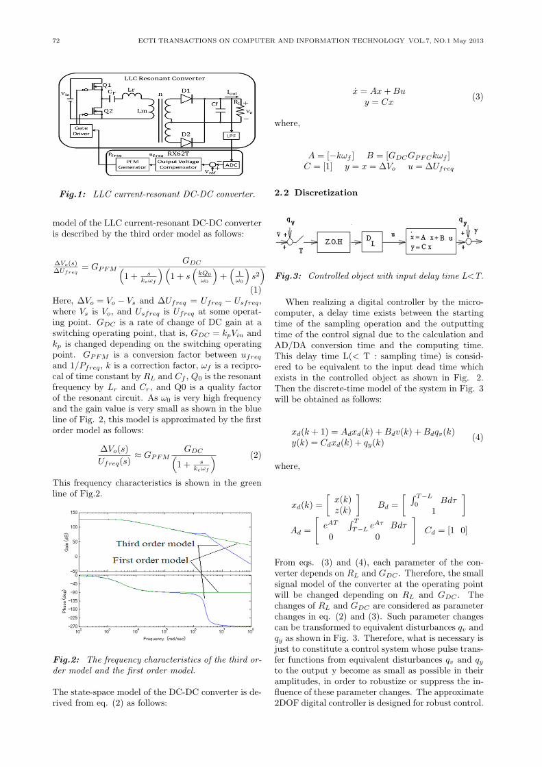
The LLC current-resonant DC-DC converter is shownin Fig. 1. In Fig. 1, Vin =24[V], C1=0.33[µF], Lr
=0.44[µH], Lm =3.5[µH], n=1.11, Cf=480[µF] andRL =25[Ω]. Iout is an output current, and vo is anoutput voltage. RX62T is a micro-computer. Vref isa reference input voltage, ufreq is a control input, andPfreq is a switching pulse frequency. A small signal
72 ECTI TRANSACTIONS ON COMPUTER AND INFORMATION TECHNOLOGY VOL.7, NO.1 May 2013
Fig.1: LLC current-resonant DC-DC converter.
model of the LLC current-resonant DC-DC converteris described by the third order model as follows:
∆Vo(s)∆Ufreq
= GPFMGDC(
1 + skcωf
)(1 + s
(kQ0
ω0
)+(
1ω0
)s2)
(1)Here, ∆Vo = Vo − Vs and ∆Ufreq = Ufreq − Usfreq,where Vs is Vo, and Usfreq is Ufreq at some operat-ing point. GDC is a rate of change of DC gain at aswitching operating point, that is, GDC = kpVin andkp is changed depending on the switching operatingpoint. GPFM is a conversion factor between ufreq
and 1/Pfreq, k is a correction factor, ωf is a recipro-cal of time constant by RL and Cf , Q0 is the resonantfrequency by Lr and Cr, and Q0 is a quality factorof the resonant circuit. As ω0 is very high frequencyand the gain value is very small as shown in the blueline of Fig. 2, this model is approximated by the firstorder model as follows:
∆Vo(s)
Ufreq(s)≈ GPFM
GDC(1 + s
kcωf
) (2)
This frequency characteristics is shown in the greenline of Fig.2.
Fig.2: The frequency characteristics of the third or-der model and the first order model.
The state-space model of the DC-DC converter is de-rived from eq. (2) as follows:
x = Ax+Buy = Cx
(3)
where,
A = [−kωf ] B = [GDCGPFCkωf ]C = [1] y = x = ∆Vo u = ∆Ufreq
2.2 Discretization
Fig.3: Controlled object with input delay time L<T.
When realizing a digital controller by the micro-computer, a delay time exists between the startingtime of the sampling operation and the outputtingtime of the control signal due to the calculation andAD/DA conversion time and the computing time.This delay time L(< T : sampling time) is consid-ered to be equivalent to the input dead time whichexists in the controlled object as shown in Fig. 2.Then the discrete-time model of the system in Fig. 3will be obtained as follows:
xd(k + 1) = Adxd(k) +Bdv(k) +Bdqv(k)y(k) = Cdxd(k) + qy(k)
(4)
where,
xd(k) =
[x(k)z(k)
]Bd =
[ ∫ T−L
0Bdτ
1
]Ad =
[eAT
∫ T
T−LeAτ Bdτ
0 0
]Cd = [1 0]
From eqs. (3) and (4), each parameter of the con-verter depends on RL and GDC . Therefore, the smallsignal model of the converter at the operating pointwill be changed depending on RL and GDC . Thechanges of RL and GDC are considered as parameterchanges in eq. (2) and (3). Such parameter changescan be transformed to equivalent disturbances qv andqy as shown in Fig. 3. Therefore, what is necessary isjust to constitute a control system whose pulse trans-fer functions from equivalent disturbances qv and qyto the output y become as small as possible in theiramplitudes, in order to robustize or suppress the in-fluence of these parameter changes. The approximate2DOF digital controller is designed for robust control.
Robust Digital Control for an LLC Current-Resonant DC-DC Converter 73
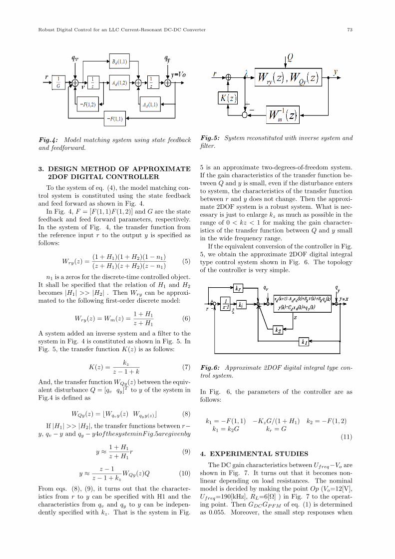
Fig.4: Model matching system using state feedbackand feedforward.
3. DESIGN METHOD OF APPROXIMATE2DOF DIGITAL CONTROLLER
To the system of eq. (4), the model matching con-trol system is constituted using the state feedbackand feed forward as shown in Fig. 4.
In Fig. 4, F = [F (1, 1)F (1, 2)] and G are the statefeedback and feed forward parameters, respectively.In the system of Fig. 4, the transfer function fromthe reference input r to the output y is specified asfollows:
Wry(z) =(1 +H1)(1 +H2)(1− n1)
(z +H1)(z +H2)(z − n1)(5)
n1 is a zeros for the discrete-time controlled object.It shall be specified that the relation of H1 and H2
becomes |H1| >> |H2| . Then Wry can be approxi-mated to the following first-order discrete model:
Wry(z) = Wm(z) =1 +H1
z +H1(6)
A system added an inverse system and a filter to thesystem in Fig. 4 is constituted as shown in Fig. 5. InFig. 5, the transfer function K(z) is as follows:
K(z) =kz
z − 1 + k(7)
And, the transfer functionWQy(z) between the equiv-alent disturbance Q = [qv qy]
T to y of the system inFig.4 is defined as
WQy(z) = ⌊Wqvy(z) Wqyy(z)⌋ (8)
If |H1| >> |H2|, the transfer functions between r−y, qv − y and qy − y4ofthesysteminFig.5aregivenby
y ≈ 1 +H1
z +H1r (9)
y ≈ z − 1
z − 1 + kzWQy(z)Q (10)
From eqs. (8), (9), it turns out that the character-istics from r to y can be specified with H1 and thecharacteristics from qv and qy to y can be indepen-dently specified with kz. That is the system in Fig.
Fig.5: System reconstituted with inverse system andfilter.
5 is an approximate two-degrees-of-freedom system.If the gain characteristics of the transfer function be-tween Q and y is small, even if the disturbance entersto system, the characteristics of the transfer functionbetween r and y does not change. Then the approxi-mate 2DOF system is a robust system. What is nec-essary is just to enlarge kz as much as possible in therange of 0 < kz < 1 for making the gain character-istics of the transfer function between Q and y smallin the wide frequency range.
If the equivalent conversion of the controller in Fig.5, we obtain the approximate 2DOF digital integraltype control system shown in Fig. 6. The topologyof the controller is very simple.
Fig.6: Approximate 2DOF digital integral type con-trol system.
In Fig. 6, the parameters of the controller are asfollows:
k1 = −F (1, 1) −KzG/(1 +H1) k2 = −F (1, 2)k1 = k2G kr = G
(11)
4. EXPERIMENTAL STUDIES
The DC gain characteristics between Ufreq−Vo areshown in Fig. 7. It turns out that it becomes non-linear depending on load resistances. The nominalmodel is decided by making the point Op (Vo=12[V],Ufreq=190[kHz], RL=6[Ω] ) in Fig. 7 to the operat-ing point. Then GDCGPFM of eq. (1) is determinedas 0.055. Moreover, the small step responses when

74 ECTI TRANSACTIONS ON COMPUTER AND INFORMATION TECHNOLOGY VOL.7, NO.1 May 2013
∆Ufreq was changed from 190 ( the operating pointin Fig. 7) to 209 are shown Fig. 8.The response ischanging depending on load resistances. Moreover, itturns out that the real responses differ from the re-sponses of the first-order models of eq. (1) consider-ably when RL is more than 25[Ω]. From the responseat RL=6[Ω] in Fig. 8, 1/kωf was decided as 260e-6.Converting eq. (1) to the discrete-time system (3)with T=10 [µs] and L=0.999T, the digital controlleris designed.
Fig.7: DC gain between Ufreq and Vo.
Fig.8: Small step responses at the operating pointOp.
First of all, H1 is determined as follows so thatthe step response of the closed loop system becomesquicker than that of the controlled object.
H1 = −0.94 (12)
Next, from |H1| >> |H2|, H2 are determined as fol-lows:
H2 = −0.1 (13)
Then F and G become as
F = [10.15 − 0.1206], G = 30.40 (14)
Next, in order to make the approximate 2DOF sys-tem more robust, it is better to set up kz as large aspossible. However, kz must be decided that the mov-ing poles p1 and p2 do not approach near H1. Then,from the root locus of Fig.9, kz is determined to be0.3.
Fig.9: Root locus.
Then, from eq. (10), the parameters of the proposedcontroller become as
k1 = −162.1, k2 = 0.1206ki = 9.108 kr = 30.40
(15)
By the way, the transfer function of the PI con-troller is as follows:
GPI(z) = Kp +KI
z − 1(16)
The parameters of the PI controller are determinedas
Kp = 50 KI = 1.5 (17)
We manufactured the current-resonant DC-DCconverter. Experimental setup is shown in Fig. 10. Inthis experiment, the micro-processor RX62T by Re-nesas Electronics Corp. is used. The Renesas RX62Tis a high-performance microcontroller with a maxi-mum operating frequency of 100MHz and a opera-tion performance of 165[MIPS]. They are equippedwith PWM timers, high-speed 12-bit A/D converter,and 10-bit A/D converter.
The simulation result of step response at load RL
=6[Ω] using the proposed controller is shown in Fig.11. This response is almost the same as the responseof the first-order delay system with the dominant poleH1. The experimental results of step responses atload RL =6[Ω] and RL =25[Ω] using the proposedcontrollers are shown in Fig. 12 and Fig.13, respec-tively. From Fig.11 and Fig.12, it turns out thatthe experimental step responses are almost the sameas the simulation one. And comparing Fig.12 withFig.13, it turns out that the experimental step re-sponses are almost the same. Even if the loads arechanged, the step responses are almost the same andare maintaining the responses by the dominant poleH1=0.94. This shows that the approximate 2DOFsystem is robust enough by setting up of kz=0.3.

Robust Digital Control for an LLC Current-Resonant DC-DC Converter 75
Fig.10: Experimental setup.
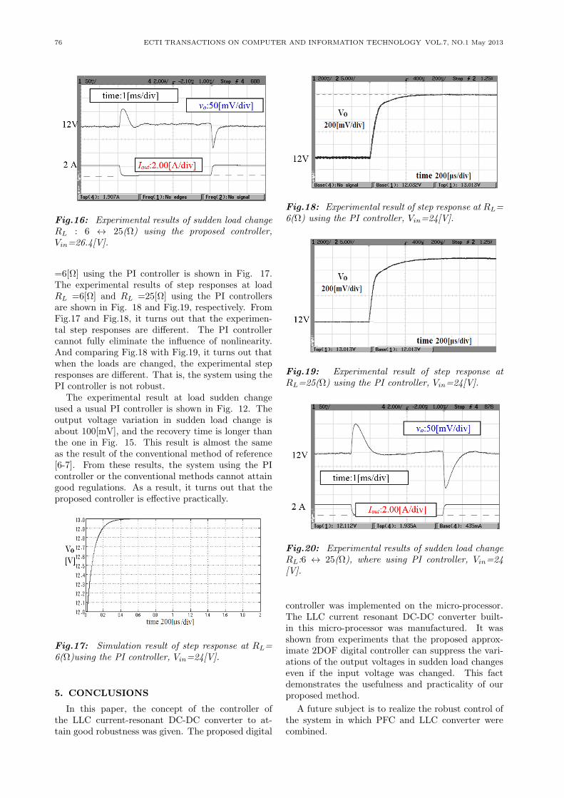
The simulation result at load sudden change(RL:6↔25[Ω]) is shown in Fig. 14. The experimentresult at load sudden change (RL:6↔ 25[Ω]) is shownin Fig. 15. It turns out that the experimental stepresponse is almost the same as the simulation one andthe output voltage regulation is suppressed to about50 [mV]. This voltage regulation is smaller than thereference [6-7]. The experiment result at load suddenchange (RL:6↔25[Ω]) when the input voltage is in-creased by 10 [%] (Vin = 26.4 [V]) is shown in Fig.16. It turns out that the experimental step responseis almost the same as the experimental one with Vin
= 24 [V]. Vin is included in GDC of eq.(3). So thechange of Vin is the one of the parameter change ofthe controlled object, that is, the parameter changeis included in the equivalent disturbance Q. Sincethe influence by change of the input voltage is sup-pressed like the change of load resistance, the outputvoltage regulation is hardly different from the one atthe change of only load resistance. That is, the pro-posed control system is robust enough. In reference[7], when the input voltage is changed, the outputvoltage regulations differ greatly. So the control sys-tem of reference [7] is not robust.
Fig.11: Simulation result of step response at RL=6(Ω)using the proposed controller, Vin=24[V].
The simulation result of step response at load RL
Fig.12: Experimental result of step response atRL=6 (Ω)using the proposed controller, Vin=24[V].
Fig.13: Experimental result of step responseRL=25(Ω) using the proposed controller, Vin=24[V].
Fig.14: Simulation result of sudden load changeRL : 6 ↔ 25(Ω)using the proposed controller,Vin=24[V].
Fig.15: Experimental results of sudden load changeRL : 6 ↔ 25(Ω) using the proposed controller,Vin=24[V].
76 ECTI TRANSACTIONS ON COMPUTER AND INFORMATION TECHNOLOGY VOL.7, NO.1 May 2013
Fig.16: Experimental results of sudden load changeRL : 6 ↔ 25(Ω) using the proposed controller,Vin=26.4[V].
=6[Ω] using the PI controller is shown in Fig. 17.The experimental results of step responses at loadRL =6[Ω] and RL =25[Ω] using the PI controllersare shown in Fig. 18 and Fig.19, respectively. FromFig.17 and Fig.18, it turns out that the experimen-tal step responses are different. The PI controllercannot fully eliminate the influence of nonlinearity.And comparing Fig.18 with Fig.19, it turns out thatwhen the loads are changed, the experimental stepresponses are different. That is, the system using thePI controller is not robust.
The experimental result at load sudden changeused a usual PI controller is shown in Fig. 12. Theoutput voltage variation in sudden load change isabout 100[mV], and the recovery time is longer thanthe one in Fig. 15. This result is almost the sameas the result of the conventional method of reference[6-7]. From these results, the system using the PIcontroller or the conventional methods cannot attaingood regulations. As a result, it turns out that theproposed controller is effective practically.
Fig.17: Simulation result of step response at RL=6(Ω)using the PI controller, Vin=24[V].
5. CONCLUSIONS
In this paper, the concept of the controller ofthe LLC current-resonant DC-DC converter to at-tain good robustness was given. The proposed digital
Fig.18: Experimental result of step response at RL=6(Ω) using the PI controller, Vin=24[V].
Fig.19: Experimental result of step response atRL=25(Ω) using the PI controller, Vin=24[V].
Fig.20: Experimental results of sudden load changeRL:6 ↔ 25(Ω), where using PI controller, Vin=24[V].
controller was implemented on the micro-processor.The LLC current resonant DC-DC converter built-in this micro-processor was manufactured. It wasshown from experiments that the proposed approx-imate 2DOF digital controller can suppress the vari-ations of the output voltages in sudden load changeseven if the input voltage was changed. This factdemonstrates the usefulness and practicality of ourproposed method.
A future subject is to realize the robust control ofthe system in which PFC and LLC converter werecombined.

Robust Digital Control for an LLC Current-Resonant DC-DC Converter 77
References
[1] J. Lazar and R. Martinelli, “Steady-State Anal-ysis of the LLC Series Resonant Converter”, Ap-plied Power Electronics Conference and Exposi-tion 2002, APEC 2001, 16th ANNUAL IEEE,pp.728-735 (2001)
[2] B. Yang, F. Lee, A. Zhang and H. Guisong,“LLC Resonant Converter for Front EndDC/DC Conversion,” Applied Power ElectronicsConference and Exposition 2002, APEC 2001,17th ANNUAL IEEE, pp.1108-1112 (2002)
[3] G. Hsieh, C. Tsai, S. Hsieh, “Design Considera-tions for LLC Series-Resonant Converter in Two-Resonant Regions,” Power Electronics SpecialistConference, PESC2007, pp.731-736 (2007)
[4] J. Jung and J. Kwon, “Theoretical Analysis andOptimal Design of LLC Resonant Converter,”European Conference on Power Electronics andApplications, pp.1-10 (2007)
[5] C. Lai, R. Lee, T. Wang and K. Shyu, “Designand Implementation of a Single-Stage LLC Res-onant Converter with High Power Factor,” IEEEInternational Symposium on Industrial Electron-ics, ISIE 2007, pp.455-460.
[6] C. Jin, T. Ninomiya and S. Tomioka, “DynamicCharacteristics of Current -Resonant DC-DCConverter,” IEIC Technical Report, EE2008-35,pp.1-6 (2008)
[7] J. Jang, M. Joung, B. Choi, and H.-G. Kim,“Dynamic Analysis and Control Design ofOptocoupler-Isolated LLC Series Resonant Con-verters with Wide Input and Load Variations,”IEEE Energy Conversion Congress and Exposi-tion,. ECCE 2009. IEEE, pp. 758 - 765 (2009)
[8] K. Higuchi, K. Nakano, T. Kajikawa, E.Takegami, S. Tomioka, K. Watanabe, “A NewDesign of Robust Digital Controller for DC-DC Converters,” IFAC 16th Triennial WorldCongress, (CD-ROM), 2005.
[9] K. Higuchi, E. Takegami, K. Nakano, T. Ka-jikawa, S. Tomioka, “Digital Robust Control forDC-DC Converter with Second-Order Charac-teristics,” ECTI-CON’2009, pp.161-169, 2009.
Tomoya Nishimura is a master’scourse student in the second yearof the The University of Electro-Communications, Tokyo, Japan. He re-ceived B. Eng. from The University ofElectro-Communications in 2011. Hisresearch interests include Power Elec-tronics, Control Engineering, DigitalSignal Processing and Embedded Sys-tems Design.
Yuto Adachi is a master’s course stu-dent in the first year of The University ofElectro-Communications, Tokyo, Japan.He received his B. Eng. degree from TheUniversity of Electro-Communications,in 2012. His research interests includePower Electronics, Control Engineering,Digital Signal Processing and EmbeddedSystems Design.
Yoshihiro Ohta received his B.Eng.from The University of Electro-Commu-nications, Tokyo, Japan, in 2010. In2012, he received M. Eng. Fromthe graduate school of The Universityof Electro-Communications. His re-search interests include Power Electron-ics, Control Engineering, Digital SignalProcessing and Embedded Systems De-sign. Now he is working at MitsubishiElectric Company. He is a member of
SICE and IEICE.
Kohji Higuchi received his Ph.D. de-gree from Hokkaido University, Sapporo,Japan in 1981. In 1980 he joined theUniversity of Electro-Communications,Tokyo, Japan, as an Research Associate,where he became an Assistant Professorin 1982 and currently an Associate Pro-fessor in the Dept. of Mechanical En-gineering and Intelligent Systems, Elec-tronic Control System Course. His inter-ests include Power Electronics, Control
Engineering and Digital Signal Processing. He is a member ofIEEE, IEICE, SICE and IEEJ.

78 ECTI TRANSACTIONS ON COMPUTER AND INFORMATION TECHNOLOGY VOL.7, NO.1 May 2013
Eiji Takegami received M. Eng. de-gree from Oita University, Oita, Japanin 1997. He received Ph.D. de-gree from The University of Electro-Communications, Tokyo in 2011. From1997 he is a Engineer, Developmentand Design of switching power sup-ply at Nippon Electric Industry Co.,Ltd.(present: TDK-LAMBDA K.K.).Heis a member of IEEE, IEICE,and the So-ciety of Instrument and Control Engi-
neers (SICE).
Satoshi Tomioka received B. Eng.degree from Tokyo Denki University,Tokyo, Japan in 1984. He receivedPh. D degree from Kyusyu Univer-sity. Fukuoka, Japan in 2010. .From1984 he is a Engineer, Development andDesign of Switching Power Supply atNEMIC-LAMBDA Ltd.(present: TDK-LAMBDA K.K.). He is a member of IE-ICE.
Kamon Jirasereeamornkul was bornin Phuket, Thailand, in 1975. He re-ceived his B.Eng. and M.Eng. inElectrical Engineering, and his Ph.D.in Electrical and Computer Engineer-ing from the King Mongkut’s Univer-sity of Technology Thonburi (KMUTT),Bangkok, Thailand, in 1997, 2001 and2006, respectively. He is currentlywith the Department of Electronic andTelecommunication Engineering, Fac-
ulty of Engineering, KMUTT. His research interests includeelectronic ballasts, high-frequency resonant power converters,and power-factor correctors.
Kosin Chamnongthai currently worksas associate professor at Electronic andTelecommunication Engineering Depart-ment, Faculty of Engineering, KingMongkut’s University of Technology(KMUTT), and also serves as editor ofECTI e-magazine, and associate editorof ELEX (IEICE Trans) during 2008-2010 and ECTI-CIT Trans since 2011until now. He served as assoc editor ofECTI-EEC Trans during 2003-2010, and
chairman of IEEE COMSOC Thailand during 2004-2007. Inorganizing conference, he has served as general chair of interna-tional and national conferences such as SISA 2012, ITC-CSCC2010, NICOGRAPH 2008, ISPACS 2008, ICESIT 2008, ICE-SIT 2007, IWAIT 2007, and 30th EECON. He has recievedB.Eng. in Applied Electronics from the University of Electro-communications, Tokyo, Japan in 1985, M.Eng. in Electri-cal Engineering from Nippon Institute of Technology, Saitama,Japan in 1987 and D.Eng. in Electrical Engineering from KeioUniversity, Tokyo, Japan in 1991. His research interests in-clude image processing, computer vision, robot vision, and sig-nal processing. He is a senior member of IEEE, and a memberof IPS, TRS, IEICE, TESA and ECTI.