robus 600-1000-en:layout 1 - nice · 2 – robus 600-1000 this parameter enables the user to assign...
TRANSCRIPT

Programmable functions using the Oview programmer
Robus600/1000
STF ROBUS 600-1000 – Rev00Firmware: RF02
2 – Robus 600-1000
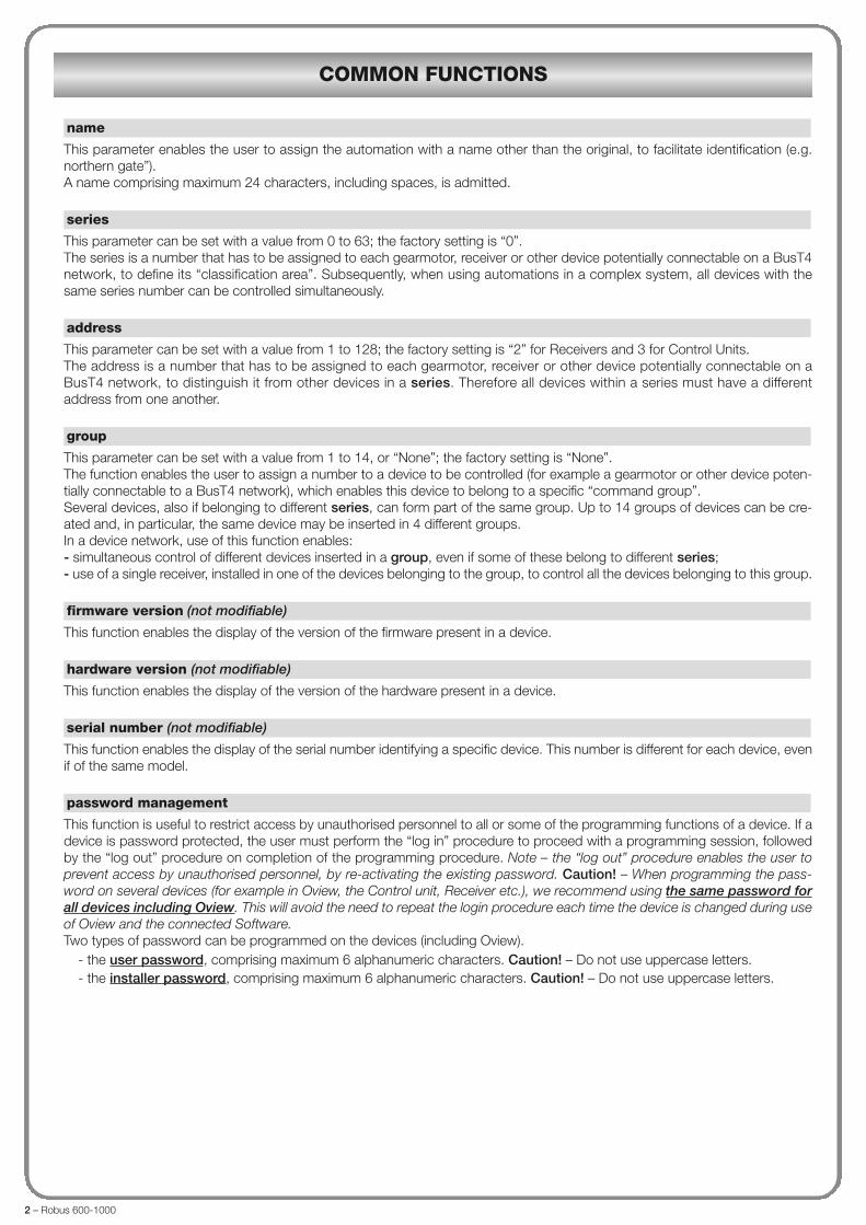
This parameter enables the user to assign the automation with a name other than the original, to facilitate identification (e.g.northern gate”).A name comprising maximum 24 characters, including spaces, is admitted.
This parameter can be set with a value from 0 to 63; the factory setting is “0”.The series is a number that has to be assigned to each gearmotor, receiver or other device potentially connectable on a BusT4network, to define its “classification area”. Subsequently, when using automations in a complex system, all devices with thesame series number can be controlled simultaneously.
This parameter can be set with a value from 1 to 128; the factory setting is “2” for Receivers and 3 for Control Units.The address is a number that has to be assigned to each gearmotor, receiver or other device potentially connectable on aBusT4 network, to distinguish it from other devices in a series. Therefore all devices within a series must have a differentaddress from one another.
This parameter can be set with a value from 1 to 14, or “None”; the factory setting is “None”.The function enables the user to assign a number to a device to be controlled (for example a gearmotor or other device poten-tially connectable to a BusT4 network), which enables this device to belong to a specific “command group”.Several devices, also if belonging to different series, can form part of the same group. Up to 14 groups of devices can be cre-ated and, in particular, the same device may be inserted in 4 different groups.In a device network, use of this function enables:- simultaneous control of different devices inserted in a group, even if some of these belong to different series;- use of a single receiver, installed in one of the devices belonging to the group, to control all the devices belonging to this group.
This function enables the display of the version of the firmware present in a device.
This function enables the display of the version of the hardware present in a device.
This function enables the display of the serial number identifying a specific device. This number is different for each device, evenif of the same model.
This function is useful to restrict access by unauthorised personnel to all or some of the programming functions of a device. If adevice is password protected, the user must perform the “log in” procedure to proceed with a programming session, followedby the “log out” procedure on completion of the programming procedure. Note – the “log out” procedure enables the user toprevent access by unauthorised personnel, by re-activating the existing password. Caution! – When programming the pass-word on several devices (for example in Oview, the Control unit, Receiver etc.), we recommend using the same password forall devices including Oview. This will avoid the need to repeat the login procedure each time the device is changed during useof Oview and the connected Software.Two types of password can be programmed on the devices (including Oview).
- the user password, comprising maximum 6 alphanumeric characters. Caution! – Do not use uppercase letters.- the installer password, comprising maximum 6 alphanumeric characters. Caution! – Do not use uppercase letters.
password management
serial number (not modifiable)
hardware version (not modifiable)
firmware version (not modifiable)
group
address
series
name
COMMON FUNCTIONS

Robus 600-1000 – 3
Installation
This function enables start-up of the procedure for learning the devices connected to the Bluebus input and the HALT input ofthe control unit of an automation. Important – To activate the device search, press “Start”.
This function enables the measurement of the distance between the Closing limit position and Opening limit position (length ofthe gate leaf). This measurement is used by the control unit to censure the precise calculation of the points (positions) at whichthe gate leaf must start to decelerate during a manoeuvre and to determine the partial opening positions. To activate the posi-tion search, press “Start”.
• maximum openingThis function enables the display of the Opening limit position, after the relative learning procedure has been completed.
• deceleration on openingThis function is expressed in metres. This enables programming of the precise point (position) at which the gate should startdecelerating before reaching the limit switch at the end of the Opening manoeuvre. After programming the required point, press“OK” to save the value.
• partial open 1This function is expressed in metres. During the opening manoeuvre this enables programming of the precise point (position) atwhich the gate stops travel (partial open). After programming the required point, press “OK” to save the value.
• partial open 2This function is expressed in metres. During the opening manoeuvre this enables programming of the precise point (position) atwhich the gate stops travel (partial open). After programming the required point, press “OK” to save the value.
• partial open 3This function is expressed in metres. During the opening manoeuvre this enables programming of the precise point (position) atwhich the gate stops travel (partial open). After programming the required point, press “OK” to save the value.
• deceleration on closingThis function is expressed in metres. This enables programming of the precise point (position) at which the gate should startdecelerating before reaching the limit switch at the end of the Closing manoeuvre. After programming the required point, press“OK” to save the value.
This function enables the user to delete the configuration of a control unit and the relative stored data, selecting items from aseries. These items are:
� positions – enables deletion of all memorised positions;� bluebus devices – enables deletion of the configuration of the Bluebus devices and the HALT input;� function values – enables deletion of all values and settings of functions envisaged on the control unit;� all – enables the deletion of all data in the Control unit memory excluding the reserved parameters: series, address, hard-ware version, software version, serial number.
Basic parameters
This parameter type is ON/OFF; the factory setting is “OFF”. This function enables the activation of automatic closure at the endof an opening manoeuvre in the control unit of the automation. If the function is active (ON) the automatic closure manoeuvrestarts at the end of the wait time programmed in the function “pause time”.If the function is not active (OFF) the Control unit operation mode is “semiautomatic”.
This parameter is expressed in seconds and can be set with a value from 0 to 250 sec.; the factory setting is 30 sec. This func-
pause time
automatic closure
data deletion
bluebus search
positions
position search
CONTROL UNIT FUNCTIONS
4 – Robus 600-1000
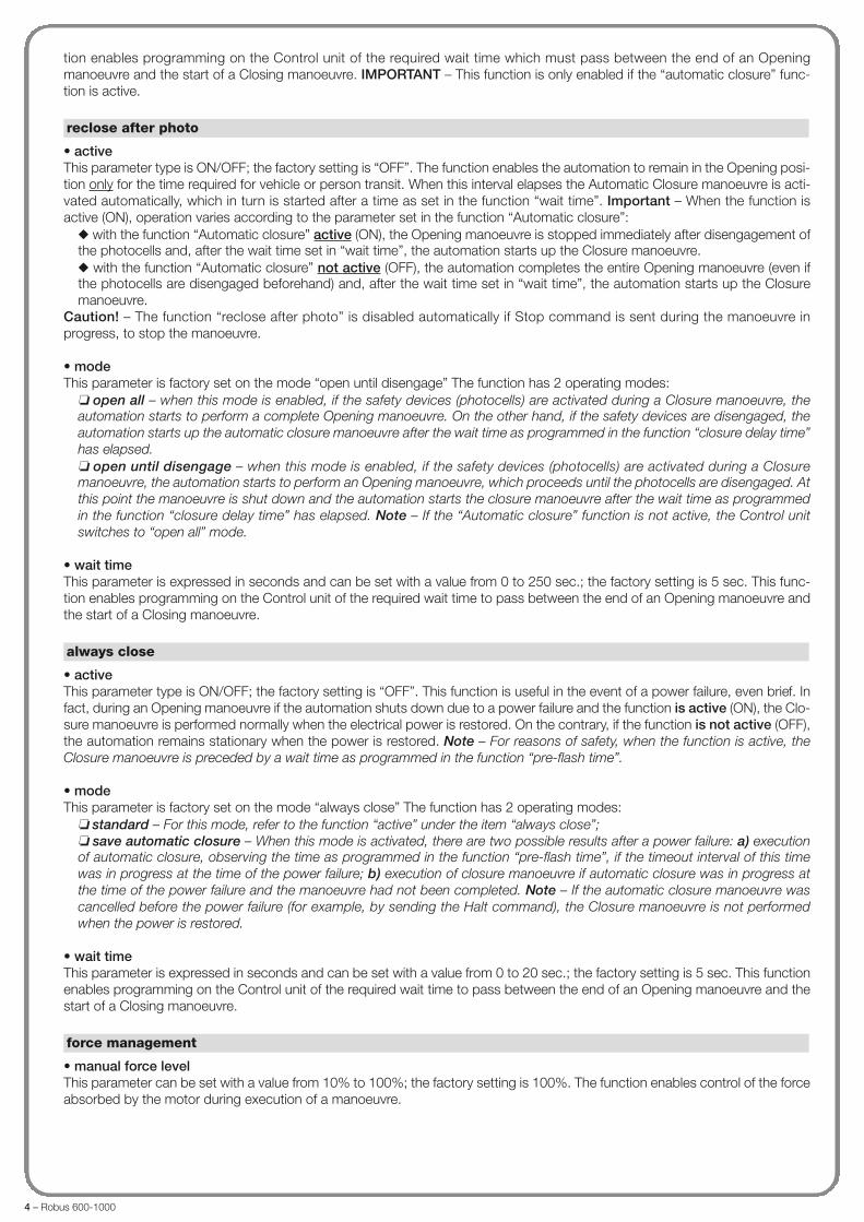
tion enables programming on the Control unit of the required wait time which must pass between the end of an Openingmanoeuvre and the start of a Closing manoeuvre. IMPORTANT – This function is only enabled if the “automatic closure” func-tion is active.
• activeThis parameter type is ON/OFF; the factory setting is “OFF”. The function enables the automation to remain in the Opening posi-tion only for the time required for vehicle or person transit. When this interval elapses the Automatic Closure manoeuvre is acti-vated automatically, which in turn is started after a time as set in the function “wait time”. Important – When the function isactive (ON), operation varies according to the parameter set in the function “Automatic closure”:
� with the function “Automatic closure” active (ON), the Opening manoeuvre is stopped immediately after disengagement ofthe photocells and, after the wait time set in “wait time”, the automation starts up the Closure manoeuvre.� with the function “Automatic closure” not active (OFF), the automation completes the entire Opening manoeuvre (even ifthe photocells are disengaged beforehand) and, after the wait time set in “wait time”, the automation starts up the Closuremanoeuvre.
Caution! – The function “reclose after photo” is disabled automatically if Stop command is sent during the manoeuvre inprogress, to stop the manoeuvre.
• modeThis parameter is factory set on the mode “open until disengage” The function has 2 operating modes:
� open all – when this mode is enabled, if the safety devices (photocells) are activated during a Closure manoeuvre, theautomation starts to perform a complete Opening manoeuvre. On the other hand, if the safety devices are disengaged, theautomation starts up the automatic closure manoeuvre after the wait time as programmed in the function “closure delay time”has elapsed.� open until disengage – when this mode is enabled, if the safety devices (photocells) are activated during a Closuremanoeuvre, the automation starts to perform an Opening manoeuvre, which proceeds until the photocells are disengaged. Atthis point the manoeuvre is shut down and the automation starts the closure manoeuvre after the wait time as programmedin the function “closure delay time” has elapsed. Note – If the “Automatic closure” function is not active, the Control unitswitches to “open all” mode.
• wait timeThis parameter is expressed in seconds and can be set with a value from 0 to 250 sec.; the factory setting is 5 sec. This func-tion enables programming on the Control unit of the required wait time to pass between the end of an Opening manoeuvre andthe start of a Closing manoeuvre.
• activeThis parameter type is ON/OFF; the factory setting is “OFF”. This function is useful in the event of a power failure, even brief. Infact, during an Opening manoeuvre if the automation shuts down due to a power failure and the function is active (ON), the Clo-sure manoeuvre is performed normally when the electrical power is restored. On the contrary, if the function is not active (OFF),the automation remains stationary when the power is restored. Note – For reasons of safety, when the function is active, theClosure manoeuvre is preceded by a wait time as programmed in the function “pre-flash time”.
• modeThis parameter is factory set on the mode “always close” The function has 2 operating modes:
� standard – For this mode, refer to the function “active” under the item “always close”;� save automatic closure – When this mode is activated, there are two possible results after a power failure: a) executionof automatic closure, observing the time as programmed in the function “pre-flash time”, if the timeout interval of this timewas in progress at the time of the power failure; b) execution of closure manoeuvre if automatic closure was in progress atthe time of the power failure and the manoeuvre had not been completed. Note – If the automatic closure manoeuvre wascancelled before the power failure (for example, by sending the Halt command), the Closure manoeuvre is not performedwhen the power is restored.
• wait timeThis parameter is expressed in seconds and can be set with a value from 0 to 20 sec.; the factory setting is 5 sec. This functionenables programming on the Control unit of the required wait time to pass between the end of an Opening manoeuvre and thestart of a Closing manoeuvre.
• manual force levelThis parameter can be set with a value from 10% to 100%; the factory setting is 100%. The function enables control of the forceabsorbed by the motor during execution of a manoeuvre.
force management
always close
reclose after photo

Robus 600-1000 – 5
• open speedThis parameter can be set with a value from 0% to 100%; the factory setting is 60%. The function enables programming of therequired motor speed during an Opening manoeuvre. Important – When this parameter is modified, the control unit updatesthe “force” and “obstacle sensitivity” values during the subsequent manoeuvres.
• open deceleration speedThis parameter can be set with a value from 0% to 100%; the factory setting is 15%. The function enables programming of therequired motor speed during the deceleration phase of an opening manoeuvre. Important – When this parameter is modified,the control unit updates the “force” and “obstacle sensitivity” values during the subsequent manoeuvres.
• close speedThis parameter can be set with a value from 0% to 100%; the factory setting is 60%. The function enables programming of therequired motor speed during a Closing manoeuvre. Important – When this parameter is modified, the control unit updates the“force” and “obstacle sensitivity” values during the subsequent manoeuvres.
• close deceleration speedThis parameter can be set with a value from 0% to 100%; the factory setting is 15%. The function enables programming of therequired motor speed during the deceleration phase of a closing manoeuvre. Important – When this parameter is modified, thecontrol unit updates the “force” and “obstacle sensitivity” values during the subsequent manoeuvres.
• activeThis parameter type is ON/OFF; the factory setting is “OFF”. When this function is set to “ON”, the values attributed to the func-tions associated with motor force and speed give the motor more power during the initial phase of a manoeuvre. This functionis useful in the presence of static friction (for example, snow or ice which obstruct the automation). Note – If the function is notactive (OFF) the Opening or Closing manoeuvre starts with a gradual acceleration.
• start-up timeThis parameter is expressed in seconds and can be set with a value from 0.5 to 5 seconds; the factory setting is 2 seconds. Thefunction enables programming of the duration of initial motor start-up. Important – The function is only effective if the “start-up”function is enabled (ON).
• activeThis parameter type is ON/OFF; the factory setting is “OFF”. When this function is set to “ON” it enables the activation of a flash-ing time, which passes between activation of the flashing light and the start of an Opening or Closing manoeuvre. This time isadjustable and useful to for an advance indication of a hazardous situation. Important – When this function is not active (OFF),the flashing light is switched on at the same time as the start of the manoeuvre.
• time in openingThis parameter is expressed in seconds and can be set with a value from 0 to 10 seconds; the factory setting is 3 seconds. Thefunction enables programming of the flashing time which indicates the imminent start of an Opening manoeuvre and is associ-ated with the “preflash” function.
• time in closingThis parameter is expressed in seconds and can be set with a value from 0 to 10 seconds; the factory setting is 3 seconds. Thefunction enables programming of the flashing time which indicates the imminent start of a Closing manoeuvre and is associat-ed with the “preflash” function.
• activeThis parameter type is ON/OFF; the factory setting is “OFF”. When this function is set to “ON”, automation power consumptioncan be reduced.
• modeThe function has 3 operating modes:
� safety – when this mode is set, at the end of a manoeuvre and when the standby time has elapsed (parameter program-mable in the function “wait time”), the control unit switches off the transmitters of the Bluebus photocells and all leds, with theexception of the Bluebus led, which flashes at a slower interval. Note – When the control unit receives a command, it auto-matically restores normal operation of the automation, and no longer in energy saving mode.� bluebus – when this mode is set, at the end of a manoeuvre and when the standby time has elapsed, the control unitswitches off the Bluebus output (devices) and all leds, with the exception of the Bluebus led, which flashes at a slower inter-val. Note – When the control unit receives a command, it automatically restores normal operation of the automation, and nolonger in energy saving mode.
speed management
stand-by
preflash
start-up

DESCRIPTION
Does not perform any command
This command is factory set to Input 1,with operating mode “step step” and oper-ating sequence “open- stop - close - open”.When this command is sent, the control unitactivates the application to complete the next
COMMAND
No command
Step step
COMMAND CATEGORY
Step stepprogram the required operating mode,selecting in Table 1-A (“command con-figuration” > “step step” > operatingmode...)
6 – Robus 600-1000
� all – when this mode is set, at the end of a manoeuvre and when the standby time has elapsed, the control unit switchesoff the Bluebus output (devices), some of the internal circuits and all leds, with the exception of the Bluebus led, which flash-es at a slower interval. Note – When the control unit receives a command, it automatically restores normal operation of theautomation, and no longer in energy saving mode.
• wait timeThis parameter is expressed in seconds and can be set with a value from 0 to 250 seconds; the factory setting is 60 seconds.The function enables programming of the time which must pass between the end of a manoeuvre and the start of the “stand-by” function, if the latter is active (ON).
This parameter type is ON/OFF; the factory setting is “OFF”. This function enables automation operation to be disabled, by set-ting the value to “ON”. In this case no type of command is acknowledged or performed, with the exception of “High prioritystep-step”, “Release”, “Release and close” and “Release and open”.
This parameter type is ON/OFF; the factory setting is “OFF”. This function disables operation of the keys present on the controlunit.
This parameter type is ON/OFF; the factory setting is “OFF”. In the case of two gearmotors which must operate in synchronisedmode, each installed on one of the two leafs of a gate or door, one must operate as a Master and the other as a Slave. To usethis configuration, set the Master motor to “OFF” and the Slave motor to “ON”.
Advanced parameters
This item covers the commands available and associable with inputs 1-2-3 present on the control unit of an automation.The commands available for each input are described in Table 1; while the command categories and relative operating modesare described in Tables 1a, 1b, 1c etc. Important – For correct operation of the control unit, the command programmedon an input must be associated with the corresponding command category and lastly the required operating mode.For configure an input, proceed as follows:01. In the section “Advanced parameters” select the item “input configuration” and then the input to be programmed. Selectthe required command and press “OK” to confirm the selection.02. Then, again in “Advanced parameters”, select “command configuration” and select the command category correspondingto the command selected previously in step 01. Then select the required operating mode.
There are three available inputs:• Input 1This function enables the programming of Input 1, assigning a command as required, from those listed in Table 1. Input 1 isfactory set with the “step-step” command, with the command category “step-step” and the operating mode “open - stop -close - open”.
• Input 2This function enables the programming of Input 2, assigning a command as required, from those listed in Table 1. Input 2 isfactory set with the “open” command, with the command category “opening” and the operating mode “open - stop - open”.
• Input 3This function enables the programming of Input 3, assigning a command as required, from those listed in Table 1. Input 3 isfactory set with the “close” command, with the command category “closing” and the operating mode “close - stop - close”.
TABLE 1: INPUT CONFIGURATION
INPUT configuration
slave mode
key lock
automation block

Robus 600-1000 – 7
manoeuvre following the previous one (or still inprogress) according to the sequence ofmanoeuvres as envisaged in the programmedsequence.Input configured as normally open.
When this command is sent the control unitactivates the application to complete theOpening manoeuvre until the position isreached as set in the function “partial open1”(Control unit functions > installation > posi-tions > partial open 1).Input configured as normally open.
When this command is sent the control unitactivates the application to complete theOpening manoeuvre until the opening limitswitch is reached.Input configured as normally open.
When this command is sent the control unitactivates the application to complete the Clos-ing manoeuvre until the closing limit switch isreached.Input configured as normally open.
When this command is sent, the control unitstops the manoeuvre in progress gradually andin a short time (not instantly).Input configured as normally open.
When this command is sent, the control unitactivates the application to complete the nextmanoeuvre following the previous one (or still inprogress) according to the sequence of ma -noeuvres as envisaged in the programmed se -quence.Important – This command is performed evenif the control unit is set with the command“block” (see Table 1).Input configured as normally open.
When this command is sent the control unitactivates the application to complete the Ope -ning manoeuvre until the position is rea ched asset in the function “partial open 2” (Control unitfunctions > installation > positions > partialopen 2).Input configured as normally open.
When this command is sent the control unitactivates the application to complete the Ope -ning manoeuvre until the position is reached asset in the function “partial open 3” (Control unitfunctions > installation > positions > partialopen 3).Input configured as normally open.
When this command is sent the control unitactivates the application to complete the Ope -ning manoeuvre until the position is reached asset in the function “partial open 3”(Control unitfunctions > installation > positions > partialopen 3).Input configured as normally open.
Partial open 1
Open
Close
Stop
High priority step step
Partial open 2
Partial open 3
Open and block
Partial openprogram the required operating mode,selecting in Table 1-B (“command con-figuration” > “partial open” > operatingmode...)
Openingprogram the required operating mode,selecting in Table 1-C (“command config-uration” > “opening” > operating mo de...)
Closingprogram the required operating mode,selecting in Table 1-B (“command config-uration” > “closing” > operating mo de...)
Stopprogram the required operating mode,selecting in Table 1-E (“command con-figuration” > “stop” > operating mode...)
Step stepprogram the required operating mode,selecting in Table 1-A (“command con-figuration” > “step step” > operatingmo de...)
Partial openprogram the required operating mode,selecting in Table 1-B (“command con-figuration” > “partial open” > operatingmo de...)
Partial openprogram the required operating mode,selecting in Table 1-B (“command con-figuration” > “partial open” > operatingmo de...)
Openingprogram the required operating mode, se -lecting in Table 1-C (“command configu-ration” > “opening” > operating mo de...)

8 – Robus 600-1000
When this command is sent the control unitactivates the application to complete the Clos-ing manoeuvre until the position is reached asset in the function “closing”(Control unit func-tions > installation > positions > closing) andthe automation is then blocked.Input configured as normally open.
When this command is sent, the control unit isblocked and does not perform any type ofcommand, with the exception of “High prioritystep-step”, “Release”, “Release and close” and“Release and open”.Input configured as normally open.
When this command is sent, the control unit isreleased restoring normal operating status (allcommands sent can be performed)Input configured as normally open.
This command enables activation of the cour-tesy light on the control unit and that program-mable on Output 1 and Output 2.The courtesy light remains active for the timeas programmed in the function “courtesy lightti me” (Control unit functions > advanced pa -rame ters > output configuration > courtesy li -ght ti me).For the courtesy light connected to Output 1,the command is only enabled when this outputis programmed in “courtesy light” mode (Con-trol unit functions > advanced parameters >out put configuration > output 1 (flash) > cour-tesy light).Note – When the courtesy light is alreadyactive and the command “timed courtesy light”is sent again, the time programmed in the func-tion “courtesy light time” is reloaded.Input configured as normally open.
This command enables activation and deactiva-tion of the courtesy light on the control unit andthat programmable on Output 1 and Output 2.For the courtesy light connected to Output 1,the command is only enabled when this outputis programmed in “courtesy light” mode (Con-trol unit functions > advanced parameters >output configuration > output 1 (flash) > cour-tesy light).CAUTION! – The courtesy light is switched offautomatically if the relative time interval elaps-es, as programmed in the function “courtesylight time” (Control unit functions > advancedparameters > output configuration > courtesylight time).Input configured as normally open.
This command is factory set to Input 1,with operating mode “ss apartment block1” and operating sequence “open- stop -close - open”.When this command is sent, the control unitactivates the application to complete the nextmanoeuvre following the previous one (or still inprogress) according to the sequence of ma -noeuvres as envisaged in the programmedsequence.Note – This apartment block step step com-mand is used for apartment blocks and in gen-eral envisages programming of all apartmentblock transmitters with a single “apartmentblock step step” key.Input configured as normally open.
Close and block
Block
Release
Timed Courtesy light
Courtesy light: on/off
Apartment block
Closingprogram the required operating mode,selecting in Table 1-D (“command config-uration” > “closing” > operating mo de...)
Step stepprogram the required operating mode, ssapartment block 1 (“command config-uration” > “step step” > operating mo -de: ss apartment block 1)

Robus 600-1000 – 9
When this command is sent, the control unit sto -ps the manoeuvre in progress and activates theapplication to execute the set operating mode.Input configured as normally closed.
When this command is sent, the control unitac tivates the application to perform the openingmanoeuvre only until the limit switch is reached.Note – This command is useful when usingcontrol photocells or a magnetic detector loop.Input configured as normally open.
When this command is sent, the control unitactivates the application according to the se -lected manoeuvre type.Input configured as normally closed.
When this command is sent, the control unitactivates the application according to theselected manoeuvre type.Input configured as normally closed.
When this command is sent, the control unitactivates the application according to the se -lected manoeuvre type.Input configured as normally closed.
When this command is sent, the control unitactivates the master (primary) leaf of the appli-cation to complete the next manoeuvre follow-ing the previous one (or still in progress) ac -cording to the sequence of manoeuvres as en -visaged in the programmed sequence.Input configured as normally open.
When this command is sent, the control unitactivates the master (primary) leaf of the appli-cation to complete an Opening manoeuvre.Input configured as normally open.
When this command is sent, the control unitactivates the master (primary) leaf of the appli-cation to complete a Closing manoeuvre.Input configured as normally open.
When this command is sent, the control unitactivates the slave (secondary) leaf of the appli-cation to complete the next manoeuvre follow-ing the previous one (or still in progress)according to the sequence of manoeuvres asenvisaged in the programmed sequence.Input configured as normally open.
When this command is sent, the control unitactivates the slave (secondary) leaf of the appli-cation to complete an Opening manoeuvre.Input configured as normally open.
When this command is sent, the control unitactivates the slave (secondary) leaf of the appli-cation to complete a Closing manoeuvre.Input configured as normally open.
Alt
Apartment block open
PhotoSafety function
Photo 2Safety function
Photo 3Safety function
Master Step Step
Master open
Master close
Slave Step Step
Slave open
Slave close
Alt on closingprogram the required operating mode,selecting in Table 1-L (“command con-figuration” > “alt on closing” > operat-ing mode...)
Openingprogram the required operating mode,apartment block 1 open (“commandconfiguration” > “opening” > operatingmode apartment block 1 open)
Photoprogram the required operating mode,selecting in Table 1-F (“command config-uration” > “photo” > operating mo de...)
Photo 2program the required operating mode,selecting in Table 1-H (“command con-figuration” > “photo 2” > operatingmo de...)
Photo 3program the required operating mode,selecting in Table 1-I (“command config-uration” > “photo 3” > operating mo de...)
Step stepprogram the required operating mode,open - stop - close - open (“commandconfiguration” > “step step” > operatingmode: open - stop - close - open)
Openingprogram the required operating mode,selecting in Table 1-C (“command con-figuration” > “opening” > operatingmo de...)
Closingprogram the required operating mode,selecting in Table 1-D (“commandcon figuration” > “closing” > operatingmo de...)
Step stepprogram the required operating mode,open - stop - close - open (“commandconfiguration” > “closing” > operatingmo de: open - stop - close - open)
Openingprogram the required operating mode,selecting in Table 1-C (“command con-figuration” > “opening” > operatingmo de...)
Closingprogram the required operating mode,selecting in Table 1-D (“command con fig-uration” > “closing” > operating mo de...)
10 – Robus 600-1000
OPERATING MODE
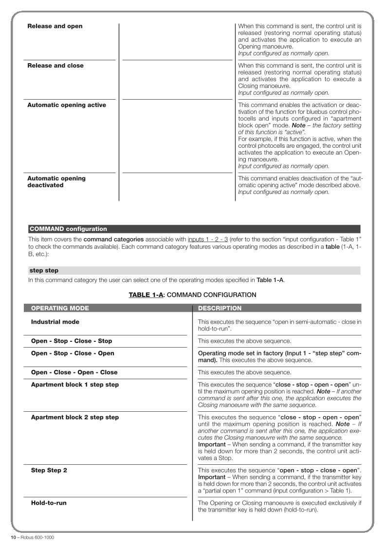
Industrial mode
Open - Stop - Close - Stop
Open - Stop - Close - Open
Open - Close - Open - Close
Apartment block 1 step step
Apartment block 2 step step
Step Step 2
Hold-to-run
DESCRIPTION
This executes the sequence “open in semi-automatic - close inhold-to-run”.
This executes the above sequence.
Operating mode set in factory (Input 1 - “step step” com-mand). This executes the above sequence.
This executes the above sequence.
This executes the sequence “close - stop - open - open” un -til the maximum opening position is reached. Note – If anothercommand is sent after this one, the application executes theClosing manoeuvre with the same sequence.
This executes the sequence “close - stop - open - open”until the maximum opening position is reached. Note – Ifanother command is sent after this one, the application exe-cutes the Closing manoeuvre with the same sequence.Important – When sending a command, if the transmitter keyis held down for more than 2 seconds, the control unit acti-vates a Stop.
This executes the sequence “open - stop - close - open”.Important – When sending a command, if the transmitter keyis held down for more than 2 seconds, the control unit activatesa “partial open 1” command (input configuration > Table 1).
The Opening or Closing manoeuvre is executed exclusively ifthe transmitter key is held down (hold-to-run).
This item covers the command categories associable with inputs 1 - 2 - 3 (refer to the section “input configuration - Table 1”to check the commands available). Each command category features various operating modes as described in a table (1-A, 1-B, etc.):
In this command category the user can select one of the operating modes specified in Table 1-A.
TABLE 1-A: COMMAND CONFIGURATION
step step
COMMAND configuration
When this command is sent, the control unit isreleased (restoring normal operating status)and activates the application to execute anOpening manoeuvre.Input configured as normally open.
When this command is sent, the control unit isreleased (restoring normal operating status)and activates the application to execute aClosing manoeuvre.Input configured as normally open.
This command enables the activation or deac-tivation of the function for bluebus control pho-tocells and inputs configured in “apartmentblock open” mode. Note – the factory settingof this function is “active”.For example, if this function is active, when thecontrol photocells are engaged, the control unitactivates the application to execute an Open-ing manoeuvre.Input configured as normally open.
This command enables deactivation of the “au t-o matic opening active” mode described above.Input configured as normally open.
Release and open
Release and close
Automatic opening active
Automatic opening deactivated

Robus 600-1000 – 11
OPERATING MODE
Open - Stop - Close - Stop
Open - Stop - Close - Open
Open - Close - Open - Close
Apartment block 1 step step
Apartment block 2 step step
Hold-to-run
Industrial mode
DESCRIPTION
Operating mode set in factory. This executes the abovesequence.
This executes the above sequence.
This executes the above sequence.
This executes the sequence “close - stop - partial open 1-partial open 1” until the maximum position is reached as pro-grammed in the function “Partial Open 1”. Note – If anothercommand is sent after this one, the application executes theClosing manoeuvre with the same sequence.
This executes the sequence “close - stop - partial open 1 -partial open 1” until the position is reached as programmed inthe function »Partial Open 1”. Note – If another command issent after this one, the application executes the Closing ma -noeuvre with the same sequence.Important – When sending a command, if the transmitter keyis held down for more than 2 seconds, the control unit acti-vates a Stop.
The Partial open 1 or Closing manoeuvre is executed exclu-sively if the transmitter key is held down (hold-to-run)..
This executes the sequence “open in semi-automatic – closein hold-to-run”.
In this command category the user can select one of the operating modes specified in Table 1-B.
TABLE 1-B: COMMAND CONFIGURATION
partial open
OPERATING MODE
Open - Stop - Open
Apartment block 1
Apartment block 2
Open 2
Hold-to-run Open
DESCRIPTION
Operating mode set in factory (Input 2 - “open” com-mand). This executes the above sequence.
This executes the sequence “open - open”.
Important – When sending a command, if the transmitter keyis held down for more than 2 seconds, the control unit acti-vates a Stop.
This executes the Opening sequence. Important – Whensending a command, if the transmitter key is held down formore than 2 seconds, the control unit activates a “partial open1” command (input configuration > Table 1).
The Opening manoeuvre is executed exclusively if the trans-mitter key is held down (hold-to-run).
In this command category the user can select one of the operating modes specified in Table 1-C.
TABLE 1-C: COMMAND CONFIGURATION
open
OPERATING MODE
Close - stop - close
DESCRIPTION
Operating mode set in factory (Input 3 - “close” comma -nd). This executes the above sequence.
In this command category the user can select one of the operating modes specified in Table 1-D.
TABLE 1-D: COMMAND CONFIGURATION
close

12 – Robus 600-1000
OPERATING MODE
stop and brief inversion
DESCRIPTION
When the control unit receives the command, it stops theClosing manoeuvre in progress and activates the applicationto perform a brief inversion in the opposite direction (Opening).Caution! – During execution of the Opening manoeuvre,this command is ignored.
In this command category the user can select one of the operating modes specified in Table 1-G.
TABLE 1-G: COMMAND CONFIGURATION
photo 1
OPERATING MODE
stop
stop and brief inversion
DESCRIPTION
Operating mode set in factory. When the control unit re -ceives the command, it stops the manoeuvre in progressgradually and in a short time (not instantly).
When the control unit receives the “stop” command, it stopsthe manoeuvre in progress and activates the application toperform a brief inversion in the opposite direction.
In this command category the user can select one of the operating modes specified in Table 1-E.
TABLE 1-E: COMMAND CONFIGURATION
stop
OPERATING MODE
stop and inversion
stop and brief inversion
stop
temporary stop
DESCRIPTION
Operating mode set in factory. When the control unitreceives the command, it stops the Closing manoeuvre inprogress and activates a total inversion (Opening). Caution! –During execution of the Opening manoeuvre, this com-mand is ignored.
When the control unit receives the command, it stops theClosing manoeuvre in progress and activates the applicationto perform a brief inversion in the opposite direction (Opening).Caution! – During execution of the Opening manoeuvre,this command is ignored.
When the control unit receives the command, it stops theClosing manoeuvre in progress. Caution! – During execu-tion of the Opening manoeuvre, this command is ignored.
When the control unit receives the command, it stops theClosing manoeuvre for the entire time that the commandremains active. Otherwise, when the command is no longeractive, the control unit activates the application to perform anOpening manoeuvre. Caution! – During execution of theOpening manoeuvre, this command is ignored.
In this command category the user can select one of the operating modes specified in Table 1-F.
TABLE 1-F: COMMAND CONFIGURATION
photo
Apartment block 1 close
Apartment block 2 close
Hold-to-run close
This executes the sequence “close - close”.
This executes the sequence “close - close”. Important –When sending a command, if the transmitter key is held downfor more than 2 seconds, the control unit activates a Stop.
The Closing manoeuvre is executed exclusively if the hold-to-run command is used.

Robus 600-1000 – 13
OPERATING MODE
stop and inversion
stop and brief inversion
stop
temporary stop
DESCRIPTION
Operating mode set in factory. When the control unit re -ceives the command, it stops the Opening manoeuvre inprogress and activates a total inversion (Closing). Caution! –During execution of the Opening manoeuvre, this com-mand is ignored.
When the control unit receives the command, it stops theOpening manoeuvre in progress and activates the applicationto perform a brief inversion in the opposite direction (Closing).Caution! – During execution of the Opening manoeuvre,this command is ignored.
When the control unit receives the command, it stops theOpening manoeuvre in progress. Caution! – During execu-tion of the Opening manoeuvre, this command is ignored.
When the control unit receives the command, it stops theOpening manoeuvre for the entire time that the commandremains active. Otherwise, when the command is no longeractive, the control unit activates the application to perform aClosing manoeuvre. Caution! – During execution of theOpening manoeuvre, this command is ignored.
In this command category the user can select one of the operating modes specified in Table 1-H.
TABLE 1-H: COMMAND CONFIGURATION
photo 2
OPERATING MODE
temporary stop
stop
DESCRIPTION
Operating mode set in factory. When the control unit re -ceives the command, it stops the Closing manoeuvre for theentire time that the command remains active. Otherwise, whenthe command is no longer active, the control unit activates theapplication to perform an Opening manoeuvre.
When the control unit receives the command, it stops themanoeuvre in progress.
In this command category the user can select one of the operating modes specified in Table 1-I.
TABLE 1-I: COMMAND CONFIGURATION
photo 3
stop
temporary stop
When the control unit receives the command, it stops theClosing manoeuvre in progress. Caution! – During execu-tion of the Opening manoeuvre, this command is ignored.
When the control unit receives the command, it stops theClosing manoeuvre for the entire time that the commandremains active. Otherwise, when the command is no longeractive, the control unit activates the application to perform anOpening manoeuvre. Caution! – During execution of theOpening manoeuvre, this command is ignored.
OPERATING MODE
alt
DESCRIPTION
When this type of function is set, when the control unit re -ceives the command, it stops the Opening manoeuvre inprogress immediately.
In this command category the user can select one of the operating modes specified in Table 1-L.
TABLE 1-L: COMMAND CONFIGURATION
alt in opening

14 – Robus 600-1000
OPERATING MODE
alt
alt and brief inversion
alt and inversion
DESCRIPTION
When the control unit receives the command, it stops theOpening manoeuvre in progress.
Operating mode set in factory. When the control unitreceives the command, it stops the Opening manoeuvre inprogress immediately and activates the application to performa brief inversion in the opposite direction (Closing).
When the control unit receives the command, it stops theOpening manoeuvre in progress immediately and activates theapplication to perform a total inversion in the opposite direc-tion (Closing).
In this command category the user can select one of the operating modes specified in Table 1-N.
TABLE 1-N: COMMAND CONFIGURATION
obstacle detection in opening
OPERATING MODE
alt
alt and brief inversion
alt and inversion
DESCRIPTION
When the control unit receives the command, it stops theClosing manoeuvre in progress.
When the control unit receives the command, it stops theClosing manoeuvre in progress immediately and activates theapplication to perform a brief inversion in the opposite direc-tion (Opening).
Operating mode set in factory. When this type of function isset, when the control unit receives the command, it stops theClosing manoeuvre in progress immediately and activates theapplication to perform a total inversion in the opposite direc-tion (Opening).
In this command category the user can select one of the operating modes specified in Table 1-O.
TABLE 1-O: COMMAND CONFIGURATION
obstacle detection in closing
OPERATING MODE
alt
alt and brief inversion
alt and inversion
DESCRIPTION
When the control unit receives the command, it stops theClosing manoeuvre in progress.
Operating mode set in factory. When the control unitreceives the command, it stops the Closing manoeuvre inprogress immediately and activates the application to performa brief inversion in the opposite direction (Opening).
When the control unit receives the command, it stops theClosing manoeuvre in progress immediately and activates theapplication to perform a total inversion in the opposite direc-tion (Opening).
In this command category the user can select one of the operating modes specified in Table 1-M.
TABLE 1-M: COMMAND CONFIGURATION
alt in closing
alt and brief inversion
alt and inversion
Operating mode set in factory. When the control unitreceives the command, it stops the Opening manoeuvre inprogress immediately and activates the application to performa brief inversion in the opposite direction (Closing).
When the control unit receives the command, it stops theOpening manoeuvre in progress immediately and activates theapplication to perform a total inversion in the opposite direc-tion (Closing).

Robus 600-1000 – 15
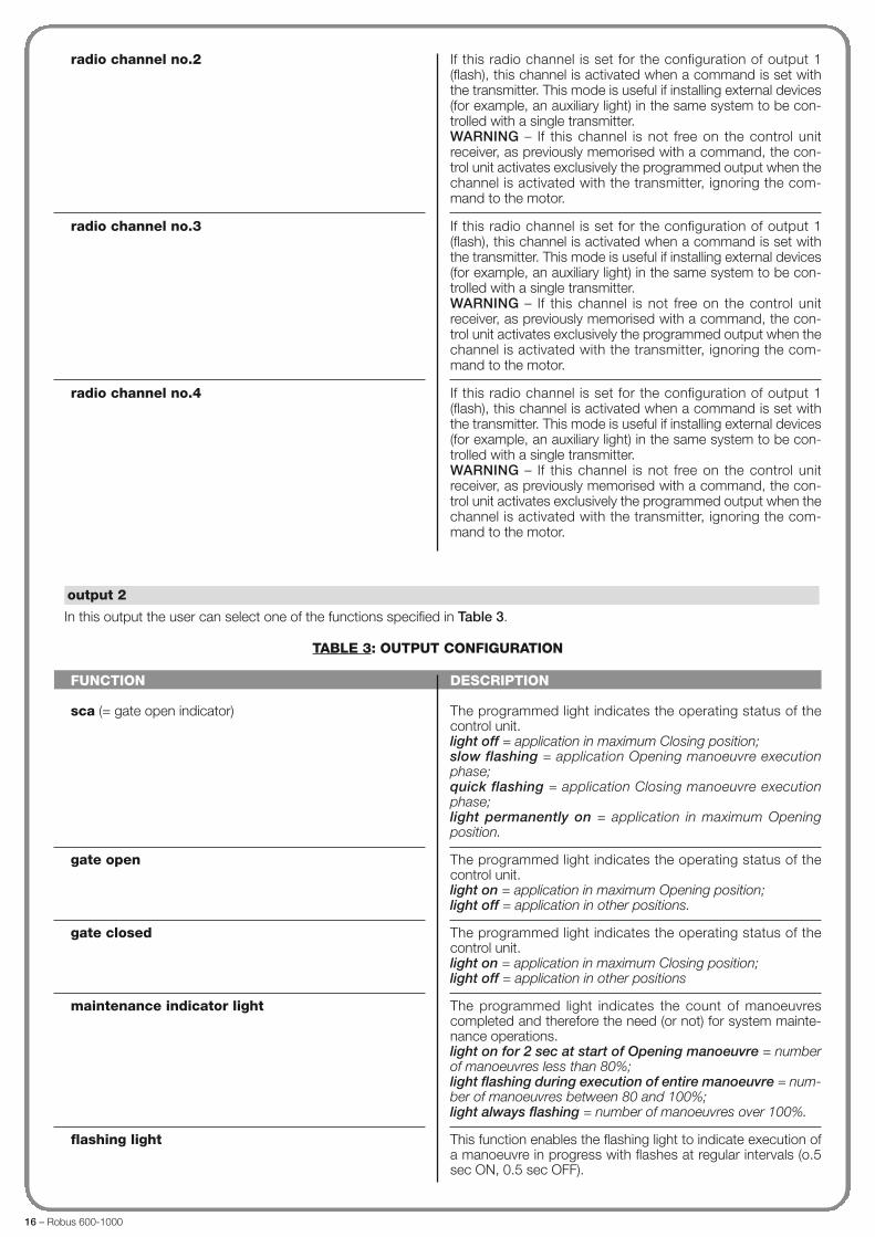
FUNCTION
sca (= gate open indicator)
gate open
gate closed
maintenance indicator light
flashing light
courtesy light
electric lock 1
suction cup 1
radio channel no.1
DESCRIPTION
The programmed light indicates the operating status of thecontrol unit.light off = application in maximum Closing position;slow flashing = application Opening manoeuvre executionphase;quick flashing = application Closing manoeuvre executionphase;light permanently on = application in maximum Openingposition.
The programmed light indicates the operating status of thecontrol unit.light on = application in maximum Opening position;light off = application in other positions.
The programmed light indicates the operating status of thecontrol unit.light on = application in maximum Closing position;light off = application in other positions.
The programmed light indicates the count of manoeuvrescompleted and therefore the need (or not) for system mainte-nance operations.light on for 2 sec at start of Opening manoeuvre = numberof manoeuvres less than 80%;light flashing during execution of entire manoeuvre = num-ber of manoeuvres between 80 and 100%;light always flashing = number of manoeuvres over 100%.
This function enables the flashing light to indicate execution ofa manoeuvre in progress with flashes at regular intervals (0.5sec ON, 0.5 sec OFF).
This function type is ON/OFF. Important – For safety reasons,as the light is not controlled by a timer, use of an adequate light,able to withstand the heat of the light emitted, is recommended.
With this function programmed, when an Opening manoeuvreis performed the electric lock is activated for a time as set inthe function “electric lock time – output configuration”.
With this function programmed, the suction cup is activatedwhen the application is in the maximum Closing position. Note– The suction cup is disabled in all other situations.When the suction cup is disabled, before an Opening manoeu-vre is started, the time interval as programmed in the function“suction cup time – output configuration” is activated, whichdelays the start of the manoeuvre.
If this radio channel is set for the configuration of output 1(flash), this channel is activated when a command is set withthe transmitter. It is useful if installing external devices (forexample, an auxiliary light) in the same system to be controlledwith a single transmitter.WARNING – If this channel is not free on the control unitreceiver, as previously memorised with a command, the con-trol unit activates exclusively the programmed output when thechannel is activated with the transmitter, ignoring the com-mand to the motor.
This item covers the functions available and associable with Outputs 1 (flash) - 2 - 3 present on the control unit of an automa-tion. Each output has various functions as described in a table (Table 2, Table 3 etc):
In this output the user can select one of the functions specified in Table 2.
TABLE 2: OUTPUT CONFIGURATION
output 1 (flash)
OUTPUT configuration
16 – Robus 600-1000
FUNCTION
sca (= gate open indicator)
gate open
gate closed
maintenance indicator light
flashing light
DESCRIPTION
The programmed light indicates the operating status of thecontrol unit.light off = application in maximum Closing position;slow flashing = application Opening manoeuvre executionphase;quick flashing = application Closing manoeuvre executionphase;light permanently on = application in maximum Openingposition.
The programmed light indicates the operating status of thecontrol unit.light on = application in maximum Opening position;light off = application in other positions.
The programmed light indicates the operating status of thecontrol unit.light on = application in maximum Closing position;light off = application in other positions
The programmed light indicates the count of manoeuvrescompleted and therefore the need (or not) for system mainte-nance operations.light on for 2 sec at start of Opening manoeuvre = numberof manoeuvres less than 80%;light flashing during execution of entire manoeuvre = num-ber of manoeuvres between 80 and 100%;light always flashing = number of manoeuvres over 100%.
This function enables the flashing light to indicate execution ofa manoeuvre in progress with flashes at regular intervals (o.5sec ON, 0.5 sec OFF).
In this output the user can select one of the functions specified in Table 3.
TABLE 3: OUTPUT CONFIGURATION
output 2
radio channel no.2
radio channel no.3
radio channel no.4
If this radio channel is set for the configuration of output 1(flash), this channel is activated when a command is set withthe transmitter. This mode is useful if installing external devices(for example, an auxiliary light) in the same system to be con-trolled with a single transmitter.WARNING – If this channel is not free on the control unitreceiver, as previously memorised with a command, the con-trol unit activates exclusively the programmed output when thechannel is activated with the transmitter, ignoring the com-mand to the motor.
If this radio channel is set for the configuration of output 1(flash), this channel is activated when a command is set withthe transmitter. This mode is useful if installing external devices(for example, an auxiliary light) in the same system to be con-trolled with a single transmitter.WARNING – If this channel is not free on the control unitreceiver, as previously memorised with a command, the con-trol unit activates exclusively the programmed output when thechannel is activated with the transmitter, ignoring the com-mand to the motor.
If this radio channel is set for the configuration of output 1(flash), this channel is activated when a command is set withthe transmitter. This mode is useful if installing external devices(for example, an auxiliary light) in the same system to be con-trolled with a single transmitter.WARNING – If this channel is not free on the control unitreceiver, as previously memorised with a command, the con-trol unit activates exclusively the programmed output when thechannel is activated with the transmitter, ignoring the com-mand to the motor.

Robus 600-1000 – 17
courtesy light
electric lock 1
suction cup 1
radio channel no.1
radio channel no.2
radio channel no.3
radio channel no.4
This function type is ON/OFF. Important – For safety reasons,as the light is not controlled by a timer, use of an adequate light,able to withstand the heat of the light emitted, is recommended.
With this function programmed, when an Opening manoeuvreis performed the electric lock is activated for a time as set inthe function “electric lock time – output configuration”.Output active 24 Vdc / max 4 W
With this function programmed, the suction cup is activatedwhen the application is in the maximum Closing position. Note– The suction cup is disabled in all other situations.When the suction cup is disabled, before an Opening manoeu-vre is started, the time interval as programmed in the function“suction cup time – output configuration” is activated, whichdelays the start of the manoeuvre.
If this radio channel is set for the configuration of output 1(flash), this channel is activated when a command is set withthe transmitter. It is useful if installing external devices (forexample, an auxiliary light) in the same system to be controlledwith a single transmitter.WARNING – If this channel is not free on the control unitreceiver, as previously memorised with a command, the con-trol unit activates exclusively the programmed output when thechannel is activated with the transmitter, ignoring the com-mand to the motor.Output active 24Vdc / max 4 W
If this radio channel is set for the configuration of output 1(flash), this channel is activated when a command is set withthe transmitter. It is useful if installing external devices (forexample, an auxiliary light) in the same system to be controlledwith a single transmitter.WARNING – If this channel is not free on the control unitreceiver, as previously memorised with a command, the con-trol unit activates exclusively the programmed output when thechannel is activated with the transmitter, ignoring the com-mand to the motor.Output active 24Vdc / max 4 W
If this radio channel is set for the configuration of output 1(flash), this channel is activated when a command is set withthe transmitter. It is useful if installing external devices (forexample, an auxiliary light) in the same system to be controlledwith a single transmitter.WARNING – If this channel is not free on the control unitreceiver, as previously memorised with a command, the con-trol unit activates exclusively the programmed output when thechannel is activated with the transmitter, ignoring the com-mand to the motor.Output active 24Vdc / max 4 W
If this radio channel is set for the configuration of output 1(flash), this channel is activated when a command is set withthe transmitter. It is useful if installing external devices (forexample, an auxiliary light) in the same system to be controlledwith a single transmitter.WARNING – If this channel is not free on the control unit receiv-er, as previously memorised with a command, the control unitactivates exclusively the programmed output when the channelis activated with the transmitter, ignoring the command to themotor.Output active 24Vdc / max 4 W
18 – Robus 600-1000
FUNCTION
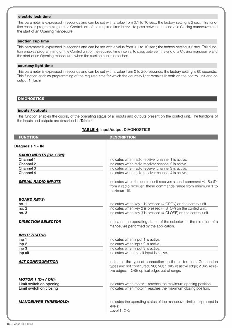
Diagnosis 1 - IN
RADIO INPUTS (On / Off):Channel 1Channel 2Channel 3Channel 4
SERIAL RADIO INPUTS
BOARD KEYS:no. 1no. 2no. 3
DIRECTION SELECTOR
INPUT STATUSinp 1inp 2inp 3inp alt
ALT CONFIGURATION
MOTOR 1 (On / Off):Limit switch on openingLimit switch on closing
MANOEUVRE THRESHOLD:
DESCRIPTION
Indicates when radio receiver channel 1 is active.Indicates when radio receiver channel 2 is active.Indicates when radio receiver channel 3 is active.Indicates when radio receiver channel 4 is active.
Indicates when the control unit receives a serial command via BusT4from a radio receiver; these commands range from minimum 1 tomaximum 15.
Indicates when key 1 is pressed (= OPEN) on the control unit.Indicates when key 2 is pressed (= STOP) on the control unit.Indicates when key 3 is pressed (= CLOSE) on the control unit.
Indicates the operating status of the selector for the direction of amanoeuvre performed by the application.
Indicates when input 1 is active.Indicates when input 2 is active.Indicates when input 3 is active.Indicates when the alt input is active.
Indicates the type of connection on the alt terminal. Connectiontypes are: not configured; NC; NO; 1 8K2 resistive edge; 2 8K2 resis-tive edges; 1 OSE optical edge; out of range.
Indicates when motor 1 reaches the maximum opening position.Indicates when motor 1 reaches the maximum closing position.
Indicates the operating status of the manoeuvre limiter, expressed inlevels:Level 1: OK;
This function enables the display of the operating status of all inputs and outputs present on the control unit. The functions ofthe inputs and outputs are described in Table 4.
TABLE 4: input/output DIAGNOSTICS
inputs / outputs
DIAGNOSTICS
This parameter is expressed in seconds and can be set with a value from 0.1 to 10 sec.; the factory setting is 2 sec. This func-tion enables programming on the Control unit of the required time interval to pass between the end of a Closing manoeuvre andthe start of an Opening manoeuvre.
This parameter is expressed in seconds and can be set with a value from 0.1 to 10 sec.; the factory setting is 2 sec. This func-tion enables programming on the Control unit of the required time interval to pass between the end of a Closing manoeuvre andthe start of an Opening manoeuvre, when the suction cup is detached.
This parameter is expressed in seconds and can be set with a value from 0 to 250 seconds; the factory setting is 60 seconds.This function enables programming of the required time for which the courtesy light remains lit both on the control unit and onoutput 1 (flash).
courtesy light time
suction cup time
electric lock time
Robus 600-1000 – 19
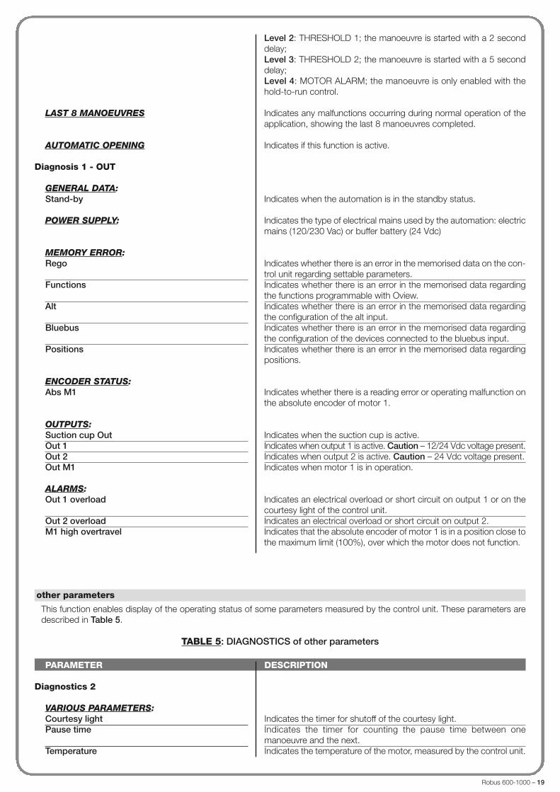
LAST 8 MANOEUVRES
AUTOMATIC OPENING
Diagnosis 1 - OUT
GENERAL DATA:Stand-by
POWER SUPPLY:
MEMORY ERROR:Rego
Functions
Alt
Bluebus
Positions
ENCODER STATUS:Abs M1
OUTPUTS:Suction cup OutOut 1Out 2Out M1
ALARMS:Out 1 overload
Out 2 overloadM1 high overtravel
Level 2: THRESHOLD 1; the manoeuvre is started with a 2 seconddelay;Level 3: THRESHOLD 2; the manoeuvre is started with a 5 seconddelay;Level 4: MOTOR ALARM; the manoeuvre is only enabled with thehold-to-run control.
Indicates any malfunctions occurring during normal operation of theapplication, showing the last 8 manoeuvres completed.
Indicates if this function is active.
Indicates when the automation is in the standby status.
Indicates the type of electrical mains used by the automation: electricmains (120/230 Vac) or buffer battery (24 Vdc)
Indicates whether there is an error in the memorised data on the con-trol unit regarding settable parameters.Indicates whether there is an error in the memorised data regardingthe functions programmable with Oview.Indicates whether there is an error in the memorised data regardingthe configuration of the alt input.Indicates whether there is an error in the memorised data regardingthe configuration of the devices connected to the bluebus input.Indicates whether there is an error in the memorised data regardingpositions.
Indicates whether there is a reading error or operating malfunction onthe absolute encoder of motor 1.
Indicates when the suction cup is active.Indicates when output 1 is active. Caution – 12/24 Vdc voltage present.Indicates when output 2 is active. Caution – 24 Vdc voltage present.Indicates when motor 1 is in operation.
Indicates an electrical overload or short circuit on output 1 or on thecourtesy light of the control unit.Indicates an electrical overload or short circuit on output 2.Indicates that the absolute encoder of motor 1 is in a position close tothe maximum limit (100%), over which the motor does not function.
PARAMETER
Diagnostics 2
VARIOUS PARAMETERS:Courtesy lightPause time
Temperature
DESCRIPTION
Indicates the timer for shutoff of the courtesy light.Indicates the timer for counting the pause time between onemanoeuvre and the next.Indicates the temperature of the motor, measured by the control unit.
This function enables display of the operating status of some parameters measured by the control unit. These parameters aredescribed in Table 5.
TABLE 5: DIAGNOSTICS of other parameters
other parameters
20 – Robus 600-1000
PARAMETER
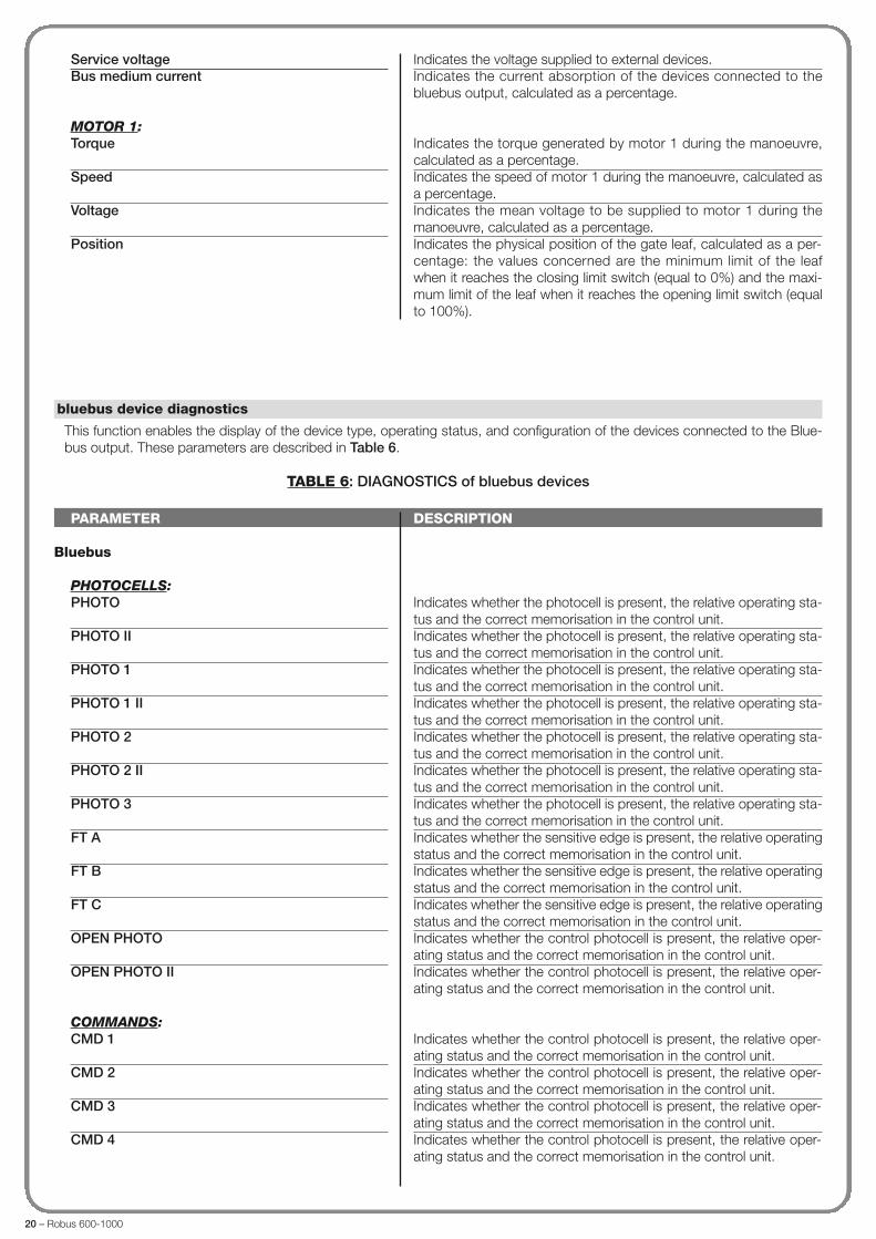
Bluebus
PHOTOCELLS:PHOTO
PHOTO II
PHOTO 1
PHOTO 1 II
PHOTO 2
PHOTO 2 II
PHOTO 3
FT A
FT B
FT C
OPEN PHOTO
OPEN PHOTO II
COMMANDS:CMD 1
CMD 2
CMD 3
CMD 4
DESCRIPTION
Indicates whether the photocell is present, the relative operating sta-tus and the correct memorisation in the control unit.Indicates whether the photocell is present, the relative operating sta-tus and the correct memorisation in the control unit.Indicates whether the photocell is present, the relative operating sta-tus and the correct memorisation in the control unit.Indicates whether the photocell is present, the relative operating sta-tus and the correct memorisation in the control unit.Indicates whether the photocell is present, the relative operating sta-tus and the correct memorisation in the control unit.Indicates whether the photocell is present, the relative operating sta-tus and the correct memorisation in the control unit.Indicates whether the photocell is present, the relative operating sta-tus and the correct memorisation in the control unit.Indicates whether the sensitive edge is present, the relative operatingstatus and the correct memorisation in the control unit.Indicates whether the sensitive edge is present, the relative operatingstatus and the correct memorisation in the control unit.Indicates whether the sensitive edge is present, the relative operatingstatus and the correct memorisation in the control unit.Indicates whether the control photocell is present, the relative oper-ating status and the correct memorisation in the control unit.Indicates whether the control photocell is present, the relative oper-ating status and the correct memorisation in the control unit.
Indicates whether the control photocell is present, the relative oper-ating status and the correct memorisation in the control unit.Indicates whether the control photocell is present, the relative oper-ating status and the correct memorisation in the control unit.Indicates whether the control photocell is present, the relative oper-ating status and the correct memorisation in the control unit.Indicates whether the control photocell is present, the relative oper-ating status and the correct memorisation in the control unit.
This function enables the display of the device type, operating status, and configuration of the devices connected to the Blue-bus output. These parameters are described in Table 6.
TABLE 6: DIAGNOSTICS of bluebus devices
bluebus device diagnostics
Service voltageBus medium current
MOTOR 1:Torque
Speed
Voltage
Position
Indicates the voltage supplied to external devices.Indicates the current absorption of the devices connected to thebluebus output, calculated as a percentage.
Indicates the torque generated by motor 1 during the manoeuvre,calculated as a percentage.Indicates the speed of motor 1 during the manoeuvre, calculated asa percentage.Indicates the mean voltage to be supplied to motor 1 during themanoeuvre, calculated as a percentage.Indicates the physical position of the gate leaf, calculated as a per-centage: the values concerned are the minimum limit of the leafwhen it reaches the closing limit switch (equal to 0%) and the maxi-mum limit of the leaf when it reaches the opening limit switch (equalto 100%).

Robus 600-1000 – 21
OTHERS:GATEBLOCK AUTOMATION
MEMORY
BUSSTAND-BY
OTHER DEVICES:COURTESY LIGHT
SUCTION CUP
LOCK
Indicates the operating status of the application.Indicates when the automation is blocked following a “Block” com-mand.Indicates a problem regarding the data related to bluebus devices,memorised in the control unit.Indicates whether there is a short circuit on the bluebus output.Indicates when the control unit is in standby status.
Indicates whether the control device is present, the relative operatingstatus and whether it is memorised correctly in the control unit.Indicates whether the control device is present, the relative operatingstatus and whether it is memorised correctly in the control unit.Indicates whether the control device is present, the relative operatingstatus and whether it is memorised correctly in the control unit.
This function enables programming of the type, and method of managing the control unit maintenance phase. There are twoapplication modes:
� automatic – When this mode is set, the “partial counter” (number of manoeuvres completed after maintenance) is updat-ed automatically according to the duration of the manoeuvres performed and the force applied on the motor;� manual – When this mode is set, the “partial count” is updated according to the number of manoeuvres performed.
A value from 0 to 16777215 (manoeuvres) can be assigned to this parameter; if the mode is set to manual, the factory settingof the parameter is 10000 (manoeuvres).This function enables programming of a reference limit, over which automation maintenance is required.
This function enables the user to check the number of manoeuvres performed by an automation since the last maintenance pro-cedure on the latter.
This parameter type is ON / OFF; the factory setting is “OFF”. This function enables deletion of the “partial count” value; this isrequired after performing maintenance on the automation.
delete maintenance
partial count
manual alarm threshold
MAINTENANCE
mode

22 – Robus 600-1000
This function enables the display of the events generated or received by the control unit. “Event” refers to a condition thatchanges the operating status of the control unit, for example: activation of an input, end of a manoeuvre, activation of a photo-cell or the alt input, etc. In this section the date and type of event can be displayed.
This function enables the firmware of a control unit to be updated with another compatible version, without the obligation tochange the board. To update, proceed as follows:01. Download the firmware update file (the software update is available at the site internet www.nice-service.com);02. In “Advanced Functions” select “Update firmware”;03. In the window displayed, select “Select file” and then select the update file previously downloaded. The data related to thesoftware of the device to be updated are displayed on the left of the window, while the data related to the update software andcompatible hardware versions are displayed on the right;04. If the file is compatible, the text “Update firmware” appears on the button, and when this is clicked, the update procedureis started. At the end of the procedure, if the message “Update completed successfully” is displayed, this means that the pro-cedure has bee completed. Otherwise, the message “Retry” appears on the button; in this case press the button again torepeat the update process.
If the update process is not completed, the user can retry a number of times, or return to the window “Device List”, selecting“Back” and then decide on how to proceed. In this window, the device previously selected will no longer be visible; to displaythe latter select the down arrow on the right of the window and select the function “Devices in boot phase”. This enables asearch for devices ready for the firmware update phase.At this point the user can retry the update process, repeating the procedure described above.If the update is still not completed successfully, contact the Nice Assistance Service.
This function enables the installer to decide which functions and parameters are to be selected for display and modifications bythe user. For example, for safety reasons, the installer can decide to prevent the user from modifying the parameters related toautomation motor force and speed.User permits can be managed exclusively by using the “installer password” (password management, common functions).Note – All parameters of the various functions of a control unit or receiver are factory set as disabled.
user permits
firmware updates
event log
ADVANCED FUNCTIONS