robotics - intranet deibhome.deib.polimi.it/gini/robot/docs/rob10bis.pdf · a robot capable of...
TRANSCRIPT

RoboticsMobility: wheels and whegs
Dipartimento di Elettronica Informazione e Bioingegneria
@ G. Gini 2015
G. Gini
Wheeled Mobile robots (WMR)
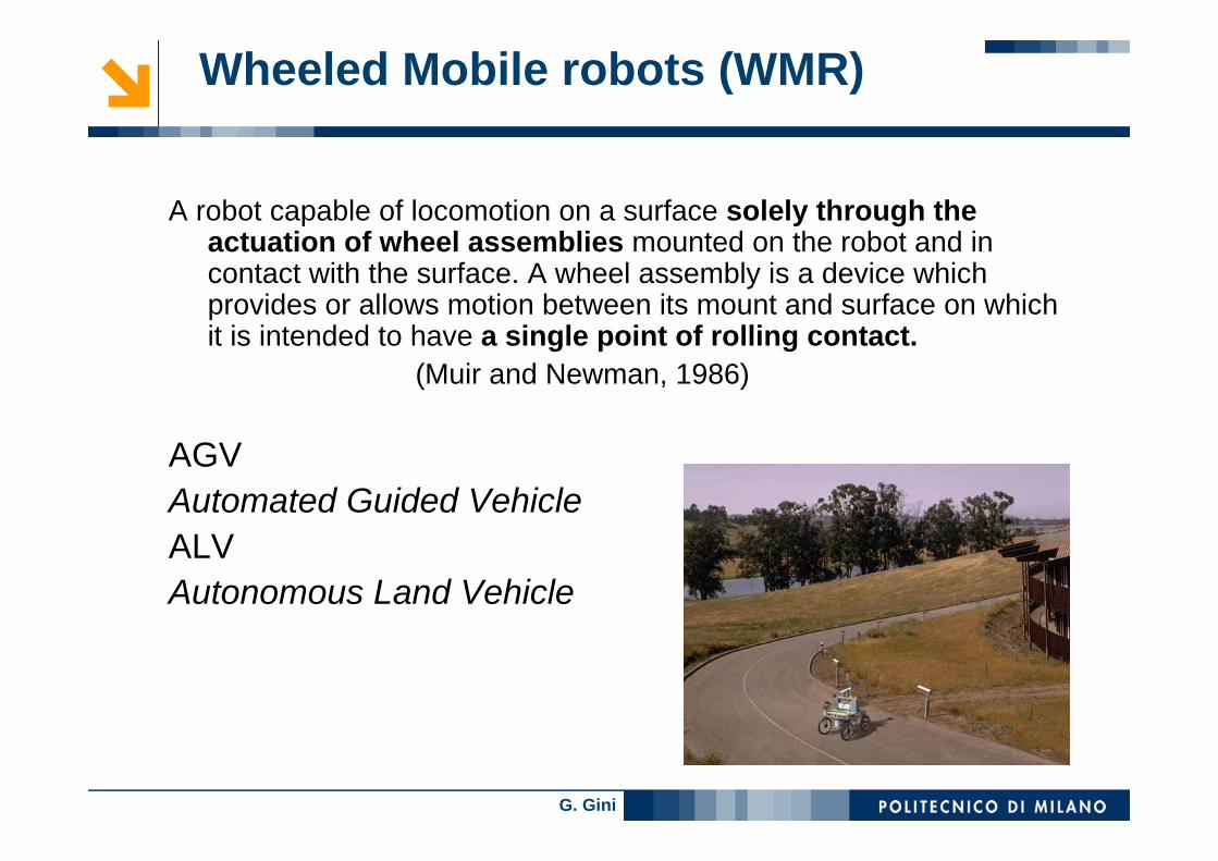
A robot capable of locomotion on a surface solely through the actuation of wheel assemblies mounted on the robot and in contact with the surface. A wheel assembly is a device which provides or allows motion between its mount and surface on whichit is intended to have a single point of rolling contact.
(Muir and Newman, 1986)
AGVAutomated Guided VehicleALVAutonomous Land Vehicle
G. Gini
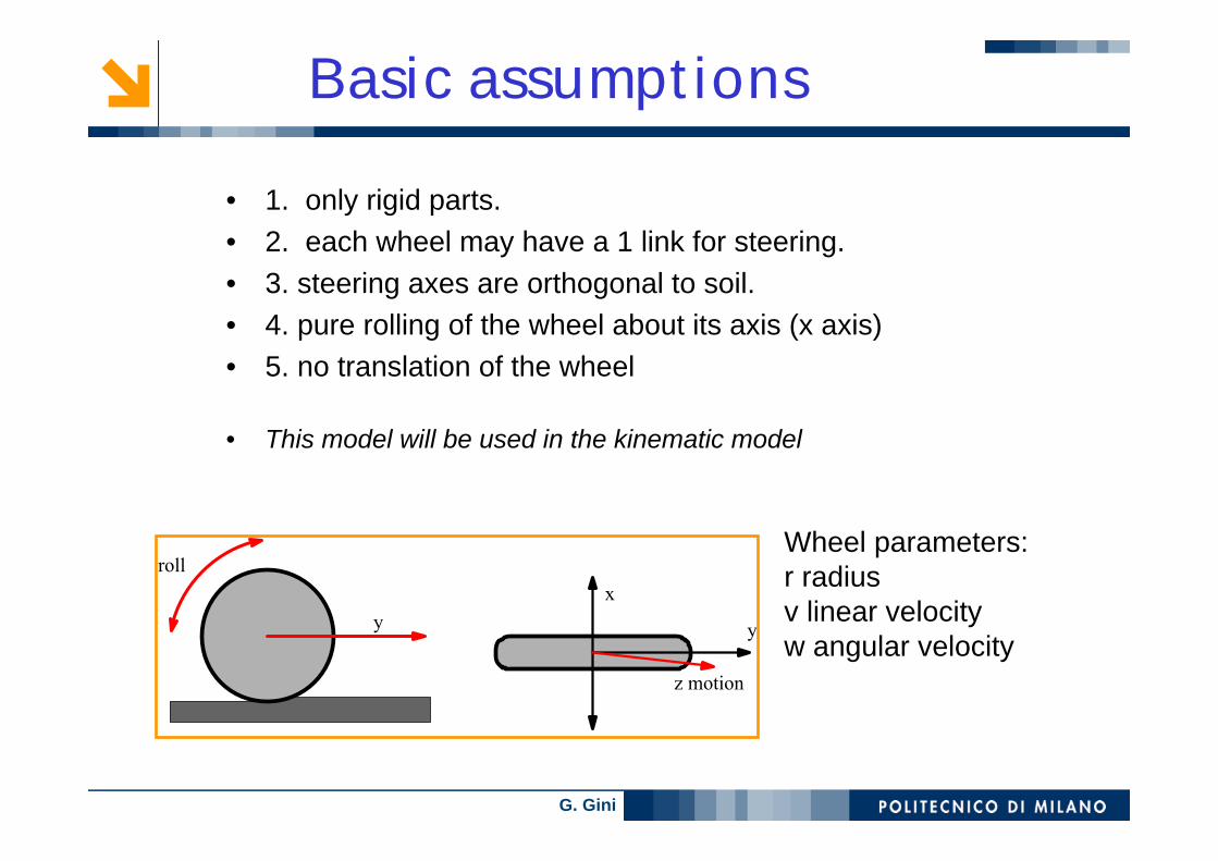
• 1. only rigid parts.• 2. each wheel may have a 1 link for steering.• 3. steering axes are orthogonal to soil.• 4. pure rolling of the wheel about its axis (x axis)• 5. no translation of the wheel
• This model will be used in the kinematic model
Basic assumptions
y
roll
z motion
x
y
Wheel parameters:r radiusv linear velocityw angular velocity

G. Gini
fixedCannot move in directions
perpendicular to the wheel plane
orientable centered
x
y
caster wheelomnidirectional
composed or Svedish
wheel

G. Gini
WMR
• Easy model• Sensible to terrain irregularities
• 2 wheels
• Omnidirectional
• tracks
• For outside terrains• Imprecisions in
movements, in particular rotations
• Free movement• Complex structure

G. Gini
Instantaneous Center of Curvature or RotationICC, ICR, CIR = point where the wheel axes intersect
ICC
Cannot move
ICC (or CIR – ICR)

G. Gini
Representing a pose
xb
yb
θ
xm, ym is in the mobile system
xb, yb is in the base system
xmym
ICC
The rotation θ is about the z axis
G. Gini
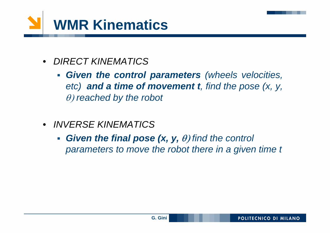
• DIRECT KINEMATICSGiven the control parameters (wheels velocities, etc) and a time of movement t, find the pose (x, y, θ) reached by the robot
• INVERSE KINEMATICSGiven the final pose (x, y, θ) find the controlparameters to move the robot there in a given time t
WMR Kinematics

G. Gini
Direct and inverse kinematics
Direct kinematics: integrating
. . . x(t), y(t), θ(t)
Inverse kinematics
wheels parameters
wheels parameters
robot pose:
x(t), y(t), θ(t) control variables:
R angular velocity ω(t) linear velocity ν(t)
control variables

G. Gini
2 wheels – differential drive
A robot for RoboCup

G. Gini
pose
v : linear velocity of the robotω : angular velocity of the robot
Control input
Differential drive - 1
2 variables independently controlledVr – velocity right wheel
Vl - velocity left wheel
Construction: 2 wheels on the same axis2 motors
-one for wheel3rd passive supporting wheel

G. Gini
differential drive - 2The wheels L and R follow a circular pathwith ω angular velocityand different curvature radius
ω(R + L/2) = vRω(R - L/2) = vL
find ω given Vl and VrSolve for R and equate
ω = vR - vL /L
find Rsolve for ω and equatePARTICULAR CASES
Rotation in placeR = 0 VR = -VL
Linear movementR = infinite VR = VL
G. Gini
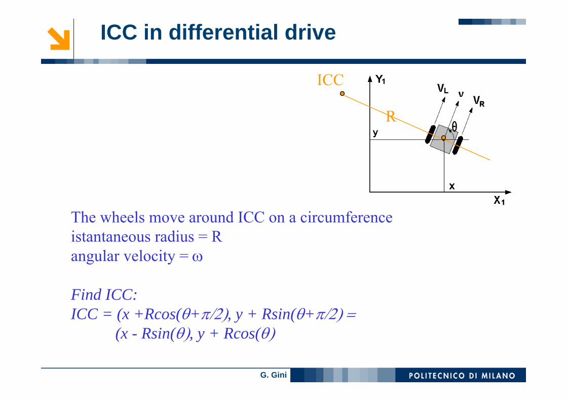
The wheels move around ICC on a circumferenceistantaneous radius = R angular velocity = ω
Find ICC: ICC = (x +Rcos(θ+π/2), y + Rsin(θ+π/2) = (x - Rsin(θ), y + Rcos(θ)
ICC
R
ICC in differential drive
G. Gini
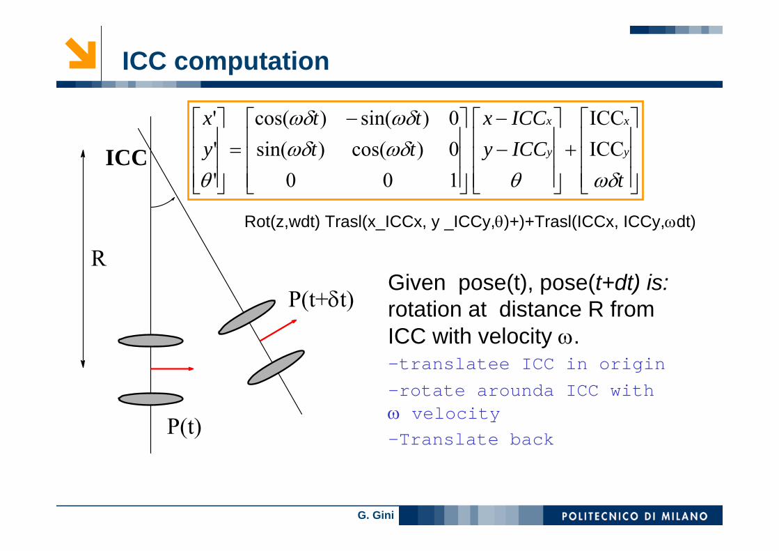
ICC computation
ICC
R
P(t)
P(t+δt)
⎥⎥⎥
⎦
⎤
⎢⎢⎢
⎣
⎡+
⎥⎥⎥
⎦
⎤
⎢⎢⎢
⎣
⎡−−
⎥⎥⎥
⎦
⎤
⎢⎢⎢
⎣
⎡ −=
⎥⎥⎥
⎦
⎤
⎢⎢⎢
⎣
⎡
tICCyICCx
tttt
yx
y
x
y
x
ωδθωδωδωδωδ
θICCICC
1000)cos()sin(0)sin()cos(
'''
Given pose(t), pose(t+dt) is: rotation at distance R fromICC with velocity ω. –translatee ICC in origin–rotate arounda ICC withω velocity–Translate back
Rot(z,wdt) Trasl(x_ICCx, y _ICCy,θ)+)+Trasl(ICCx, ICCy,ωdt)

G. Gini
Differential Drive - equations
R
ICCω
(x,y)
y
l/2
θx
vl
v r
lvv
vvv
vvvvlR
lRvlRv
lr
lr
lr
rl
l
r
−=
+=
−+
=
−=+=
ω
ωω
2
)()(
2
)2/()2/(
]cos,sin[ θθ RyRxICC +−=

G. Gini
Integrate to obtain position
VR
VL
2d
ICCR(t)
robot’s turning radius
ω(t)
ω = ( VR - VL ) / 2d
R = 2d ( VR + VL ) / ( VR - VL )
V = ωR = ( VR + VL ) / 2
Vx = V(t) cos(θ(t))
Vy = V(t) sin(θ(t))
with
x
y
x(t) = ∫ V(t) cos(θ(t)) dt
y(t) = ∫ V(t) sin(θ(t)) dt
θ(t) = ∫ ω(t) dt
Thus,
Position from velocity
G. Gini
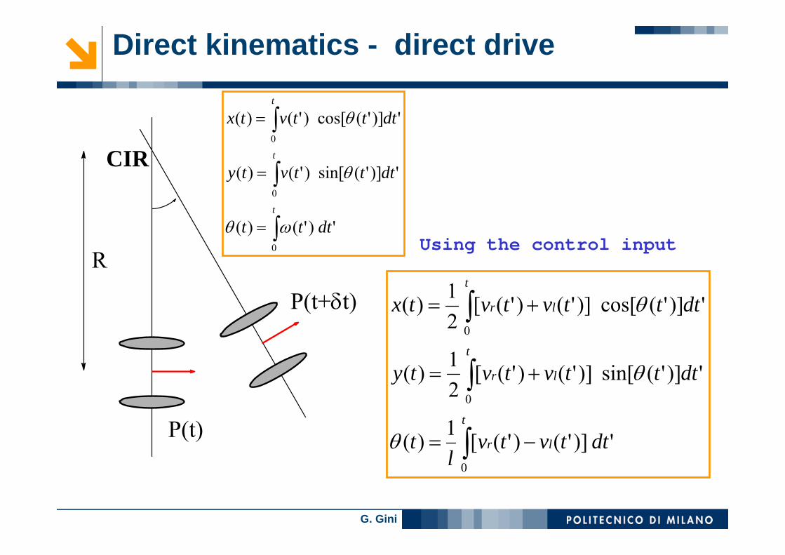
Direct kinematics - direct drive
CIR
R
P(t)
P(t+δt)
')]'()'([1)(
')]'(sin[)]'()'([21)(
')]'(cos[)]'()'([21)(
0
0
0
∫
∫
∫
−=
+=
+=
t
lr
t
lr
t
lr
dttvtvl
t
dtttvtvty
dtttvtvtx
θ
θ
θ
Using the control input')'()(
')]'(sin[)'()(
')]'(cos[)'()(
0
0
0
∫
∫
∫
=
=
=
t
t
t
dttt
dtttvty
dtttvtx
ωθ
θ
θ
G. Gini
VR(t)
VL (t)
starting position final position
x
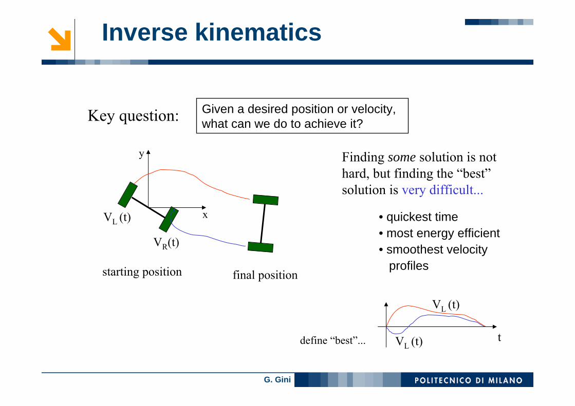
y Finding some solution is not hard, but finding the “best”solution is very difficult...
• quickest time• most energy efficient• smoothest velocity
profiles
VL (t)
tVL (t)
Key question: Given a desired position or velocity, what can we do to achieve it?
define “best”...
Inverse kinematics
G. Gini
Inverse kinematics
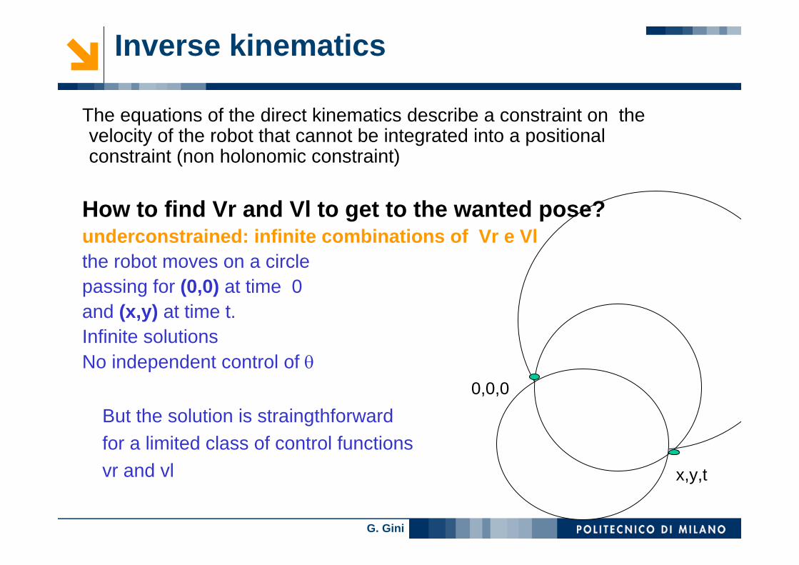
The equations of the direct kinematics describe a constraint on the velocity of the robot that cannot be integrated into a positionalconstraint (non holonomic constraint)
How to find Vr and Vl to get to the wanted pose? underconstrained: infinite combinations of Vr e Vlthe robot moves on a circlepassing for (0,0) at time 0 and (x,y) at time t. Infinite solutionsNo independent control of θ
But the solution is straingthforwardfor a limited class of control functionsvr and vl
0,0,0
x,y,t

G. Gini
Usual approach: decompose the problem and control only a few DOF at a time
VR(t)
VL (t)
starting position final position
x
y
Differential Drive
(1) turn so that the wheels are parallel to the line between the original and final position of the robot origin.
-VL (t) = VR (t) = Vmax

G. Gini
Usual approach: decompose the problem and control only a few DOF at a time
VR(t)
VL (t)
starting position final position
x
y
Differential Drive
(1) turn so that the wheels are parallel to the line between the original and final position of the robot origin.
(2) drive straight until the robot’s origin coincides with the destination
-VL (t) = VR (t) = Vmax
VL (t) = VR (t) = Vmax

G. Gini
Usual approach: decompose the problem and control only a few DOF at a time
VR(t)
VL (t)
starting position final position
x
y
Differential Drive
(1) turn so that the wheels are parallel to the line between the original and final position of the robot origin.
(2) drive straight until the robot’s origin coincides with the destination
(3) rotate again in order to achieve the desired final orientation
-VL (t) = VR (t) = Vmax
VL (t) = VR (t) = Vmax
-VL (t) = VR (t) = Vmax
VL (t)
tVR (t)
G. Gini
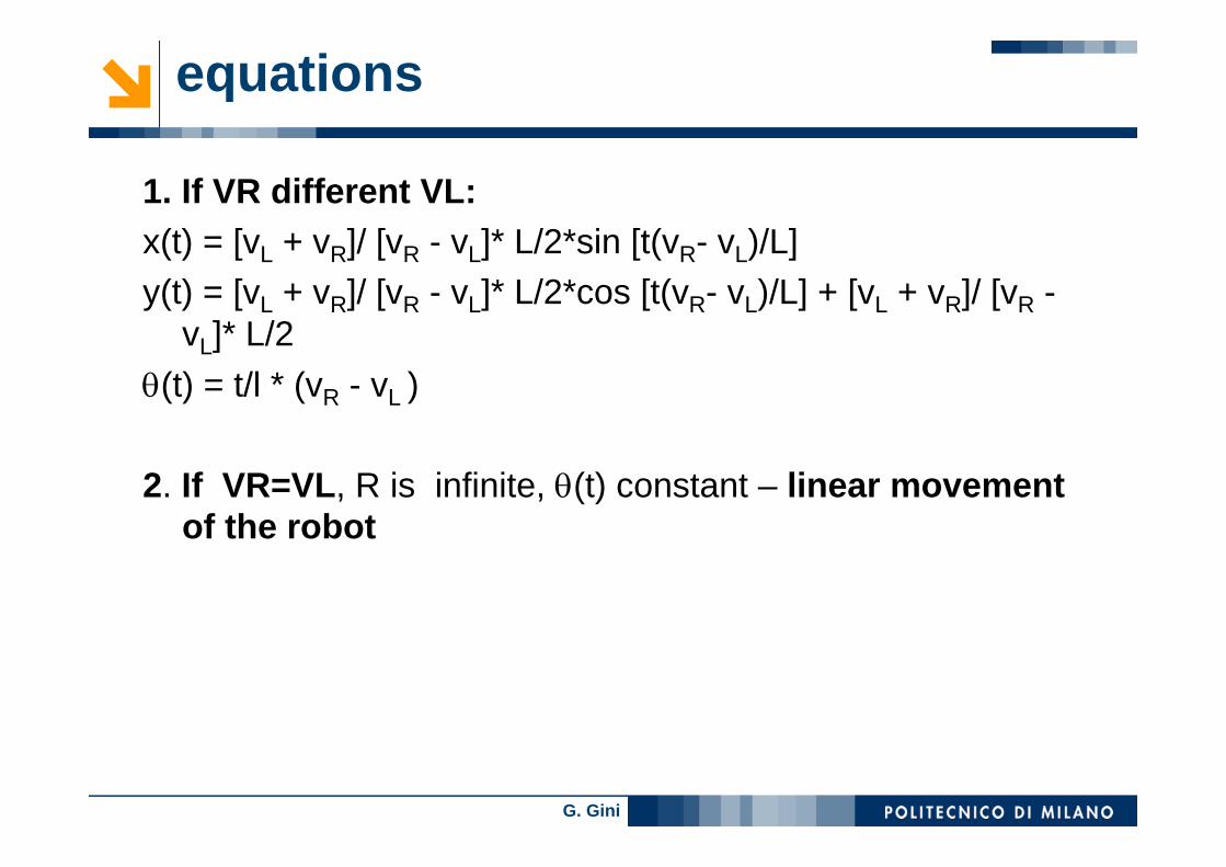
equations
1. If VR different VL:x(t) = [vL + vR]/ [vR - vL]* L/2*sin [t(vR- vL)/L] y(t) = [vL + vR]/ [vR - vL]* L/2*cos [t(vR- vL)/L] + [vL + vR]/ [vR -
vL]* L/2θ(t) = t/l * (vR - vL )
2. If VR=VL, R is infinite, θ(t) constant – linear movementof the robot
G. Gini
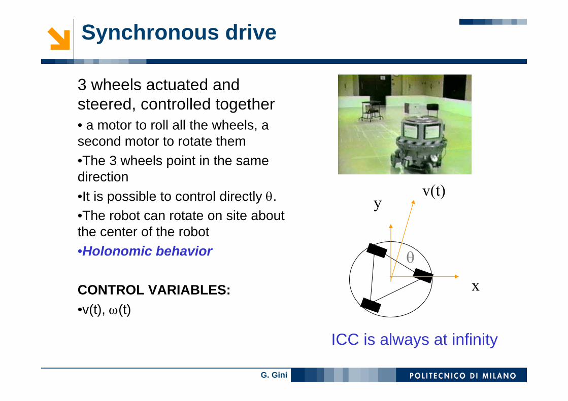
Synchronous drive
3 wheels actuated and steered, controlled together• a motor to roll all the wheels, a second motor to rotate them•The 3 wheels point in the same direction•It is possible to control directly θ. •The robot can rotate on site aboutthe center of the robot•Holonomic behavior
CONTROL VARIABLES:•v(t), ω(t)
x
yv(t)
θ
ICC is always at infinity

G. Gini
synchronous drive kinematics - 1
• DK: rotation around the robot center at angularvelocity ω(t), translation at linear velocity v(t). ω and v are directly controlledICC is at infinite distanceSteering changes the direction of ICC
Particular cases:v(t) = 0, w(t) = w for Δt, the robot rotates in placev(t) = v, w(t) = 0 for Δt, the robot moves linearly

G. Gini
Synchonous Drive kinematics - 2
Inverse kinematicsConsider that1. v(t) = 0 and ω(t) = ω for δt, then the robot rotates in place2. v(t) = v and ω(t) = 0 for δt, then the robot moves in the
direction it is pointing
θ
y
x
v(t)
ω( )t
')'()(
')]'(sin[)'()(
')]'(cos[)'()(
0
0
0
∫
∫
∫
=
=
=
t
t
t
dttt
dtttvty
dtttvtx
ωθ
θ
θ
G. Gini
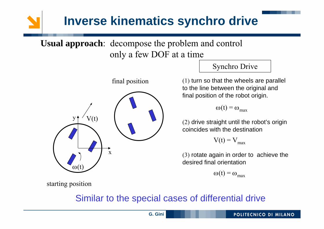
Usual approach: decompose the problem and control only a few DOF at a time
V(t)
ω(t)
starting position
final position
x
y
Synchro Drive
(1) turn so that the wheels are parallel to the line between the original and final position of the robot origin.
(2) drive straight until the robot’s origin coincides with the destination
(3) rotate again in order to achieve the desired final orientation
ω(t) = ωmax
V(t) = Vmax
ω(t) = ωmax
Inverse kinematics synchro drive
Similar to the special cases of differential drive

G. Gini
Other steered wheels
Tricicle (2 passive wheels, one actuated and steerable) as in AGV.
Robots that do not use eitherdifferential or synchronous drive have both wheels that can besteered and fixed wheels
Bicycle (1 fixed and 1 stearable)
ICC

G. Gini
• Ackermann Steering
Car-like (2 fixed and 2 steerable)
G. Gini
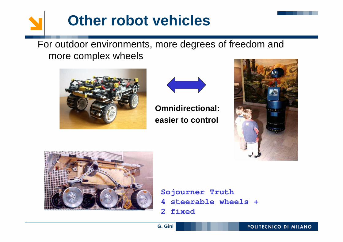
Other robot vehiclesFor outdoor environments, more degrees of freedom and
more complex wheels
Omnidirectional: easier to control
Sojourner Truth4 steerable wheels + 2 fixed
G. Gini
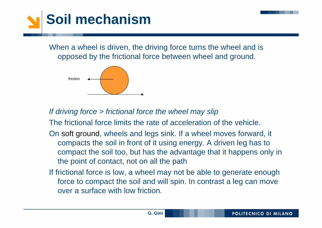
Soil mechanism
When a wheel is driven, the driving force turns the wheel and isopposed by the frictional force between wheel and ground.
If driving force > frictional force the wheel may slipThe frictional force limits the rate of acceleration of the vehicle.On soft ground, wheels and legs sink. If a wheel moves forward, it
compacts the soil in front of it using energy. A driven leg has to compact the soil too, but has the advantage that it happens only in the point of contact, not on all the path
If frictional force is low, a wheel may not be able to generate enough force to compact the soil and will spin. In contrast a leg can move over a surface with low friction.
friction

G. Gini
Tracked vehicles
• Kinematics as in differential drive
v of inside and outside tracksr diameter of the wheel• vo = rω0
• vi = rωi
It is necessary a model of the slippingTracks eliminate most of the sinking
problems• iRobot, 4 tracks

G. Gini
tracks
G. Gini
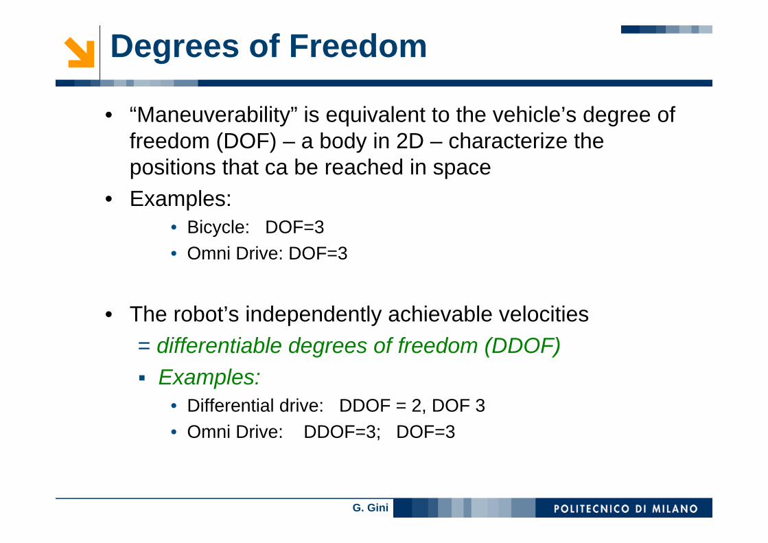
Degrees of Freedom
• “Maneuverability” is equivalent to the vehicle’s degree of freedom (DOF) – a body in 2D – characterize the positions that ca be reached in space
• Examples:• Bicycle: DOF=3• Omni Drive: DOF=3
• The robot’s independently achievable velocities= differentiable degrees of freedom (DDOF)
Examples:• Differential drive: DDOF = 2, DOF 3• Omni Drive: DDOF=3; DOF=3

G. Gini
Degrees of Freedom -> Holonomy
• DOF degrees of freedom:Robots ability to achieve various poses
• DDOF differentiable degrees of freedom: Robots ability to achieve various path
HolonomicA holonomic kinematic constraint can be expressed as an explicit function of position variables onlyA non-holonomic constraint requires a different relationship, such as the derivative of a position variableFixed and steered standard wheels impose non-holonomic constraints
DOFDDOF≤
G. Gini
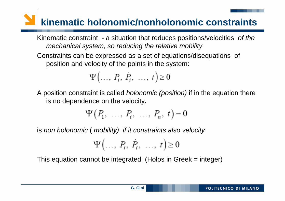
kinematic holonomic/nonholonomic constraintsKinematic constraint - a situation that reduces positions/velocities of the
mechanical system, so reducing the relative mobilityConstraints can be expressed as a set of equations/disequations of
position and velocity of the points in the system:
A position constraint is called holonomic (position) if in the equation thereis no dependence on the velocity.
is non holonomic ( mobility) if it constraints also velocity
This equation cannot be integrated (Holos in Greek = integer)

G. Gini
Example holonomic constraints
rolling cylinder6 coordinates, x, y, z, r, θ, φ5 constraints:
z=0, since it rolls on the planer = constantφ = 0, the plane faces are orthogonal to the planespace s = (x2 + y2)1/2 – it replaces 2 coordinates with 1s’ = aθ’ if the cylinder rolls without slipping- in holonomic form it isds= adθ so s-s0= a(θ−θ0), a relation between coordinates so holonomic
only 1 degree of mobility (6 – 5), s or θ.

G. Gini
Example non holonomic constraint
A thin disk rolling on an horizontal plane• Six coordinates as before• Holonomic constraints:
Z=0R=a=constantBut it can spin about both θ (roll) and, φ (turn) so it isnon holonomic
5 degrees of freedom• Since the disk can turn (change φ) it can roll from one
place to another by different routes and so the distance in the plane space s = (x2 + y2)1/2 is not related to the angle θ, as it was in the cylinder, and so this constraint does notlead to a definite condition on the coordinates.
φ

G. Gini
Restrict DOF or velocity
Each configuration of a system is univocally determinedby n independent parameters q1, ..., qn;
n degrees of freedomThe holonomic constraints subtract a degree of
freedom for each constraint equationThe non holonomic constraints restrict only velocity:
- they allow to reach any position, so they do notreduce the degrees of freedom. - some paths are not allowed while any position can be reached.imagine a car; whilst it is possible for it to be in any position on the road, it is not possible for it to move sideways.
G. Gini
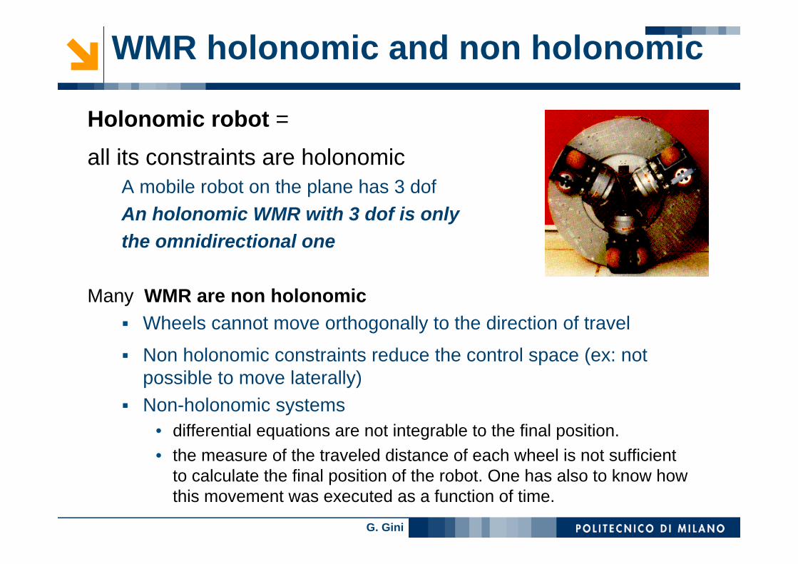
WMR holonomic and non holonomic
Holonomic robot =
all its constraints are holonomicA mobile robot on the plane has 3 dofAn holonomic WMR with 3 dof is onlythe omnidirectional one
Many WMR are non holonomicWheels cannot move orthogonally to the direction of travel
Non holonomic constraints reduce the control space (ex: not possible to move laterally)Non-holonomic systems
• differential equations are not integrable to the final position. • the measure of the traveled distance of each wheel is not sufficient
to calculate the final position of the robot. One has also to know how this movement was executed as a function of time.

G. Gini
Free movement (holonomic robot)
RIV, IspraService robot for nuclear waste store
G. Gini
Control of WMR• The objective of a kinematic controller is to follow a
trajectory described by its position and/or velocity profiles as function of time.
• Given 2 poses (qi and qf) find a trajectory that followsthe kinematic constraints
there are possible trajectories also for non holonomicrobotsusually the kinematic model is usedusually mobile robots are underactuated – forinstance the differential drive has 2 input Vl and Vrand 3 generalized coordinates x, y, θ
• Often mobile robots use open loop control
G. Gini
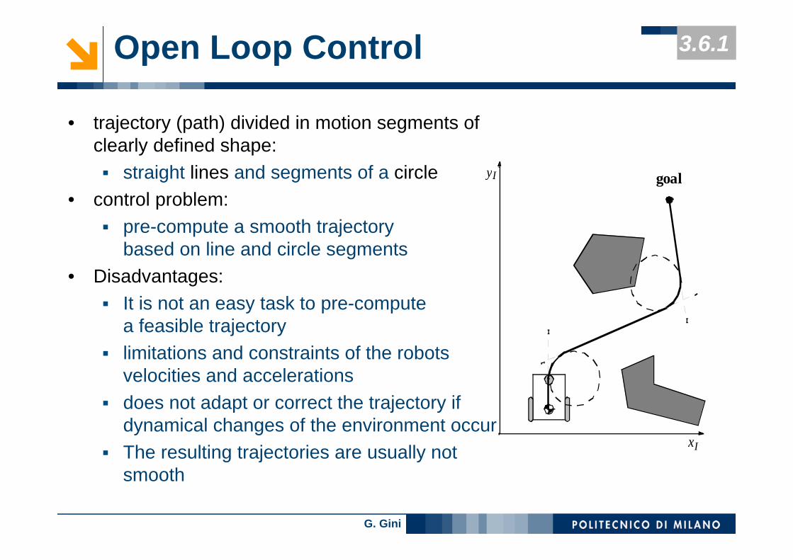
Open Loop Control
• trajectory (path) divided in motion segments of clearly defined shape:
straight lines and segments of a circle• control problem:
pre-compute a smooth trajectory based on line and circle segments
• Disadvantages:It is not an easy task to pre-compute a feasible trajectory limitations and constraints of the robots velocities and accelerationsdoes not adapt or correct the trajectory if dynamical changes of the environment occurThe resulting trajectories are usually not smooth
yI
xI
goal
3.6.1

G. Gini
Whegs
• Wheels + legs• Simple control
• RHEX, MiniWhegs
G. Gini
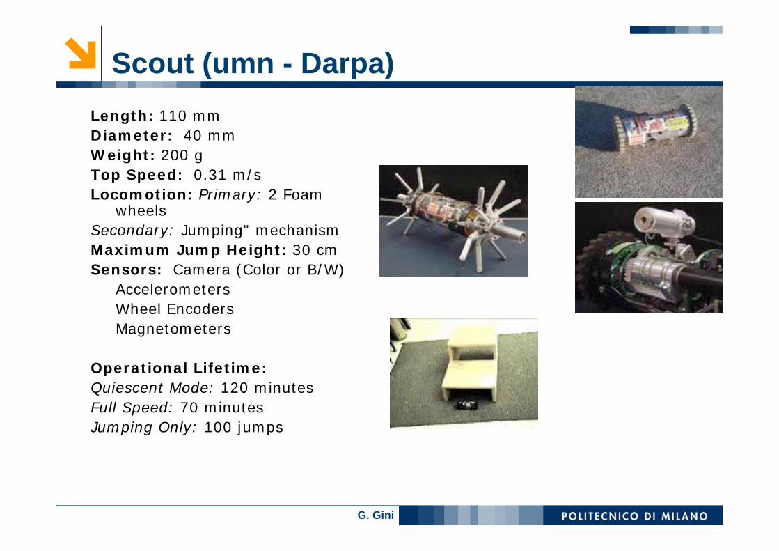
Scout (umn - Darpa)Length: 110 mmDiameter: 40 mmWeight: 200 gTop Speed: 0.31 m/sLocomotion: Primary: 2 Foam
wheelsSecondary: Jumping" mechanismMaximum Jump Height: 30 cmSensors: Camera (Color or B/W)
AccelerometersWheel EncodersMagnetometers
Operational Lifetime:Quiescent Mode: 120 minutesFull Speed: 70 minutesJumping Only: 100 jumps
G. Gini
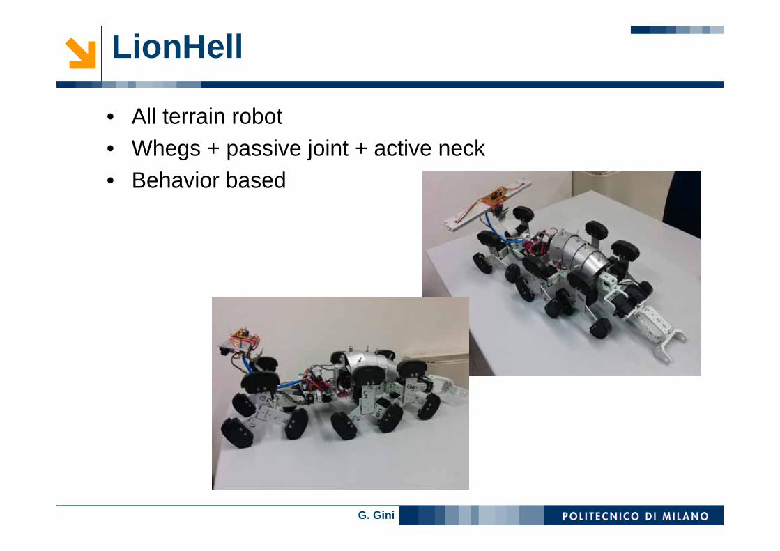
LionHell
• All terrain robot• Whegs + passive joint + active neck• Behavior based

G. Gini
Robots to move in air
• Flying robotsFixed wings vehiclesMobile wings vehiclesquadrotors

G. Gini
Robots to move in water
Acquatic vehicles: two basic designs are torpedo-like structures, with a single propellerBodys with a collection of thrusters
New design is bioinspired and uses soft materials.In general they operate in a tethered manner, connected to a
support vessel that provides power and communication

G. Gini
spheroA. Charging Dock The ball rests in a dock that uses an induction system to transfer electricity to the batteries. B. Wheels Two independently controlledrubber-rimmed wheels inside the Sphero steerand drive the ball at up to 1.2 m/sec C. Top Slip Bearing braces the mechanismin order to keep the wheels in firm contactwith the shell.D. Printed Circuit Board A processorcombines data from a three-axisaccelerometer and a gyroscope to produce the precise measurements of the Sphero’s roll, pitch, and yaw. These measurements are required to respond correctly to commandsradioed by a smart phone over a Bluetooth connection E. Bluetooth Radio and Antenna Thissystem, with a maximum range of 50 meters, is used to communicate with mobile devices.F. Multicolor LED The light from a single LED package with red, green, and blueelements is diffused to make the Sphero glow. Different colors signal information.
G. Gini
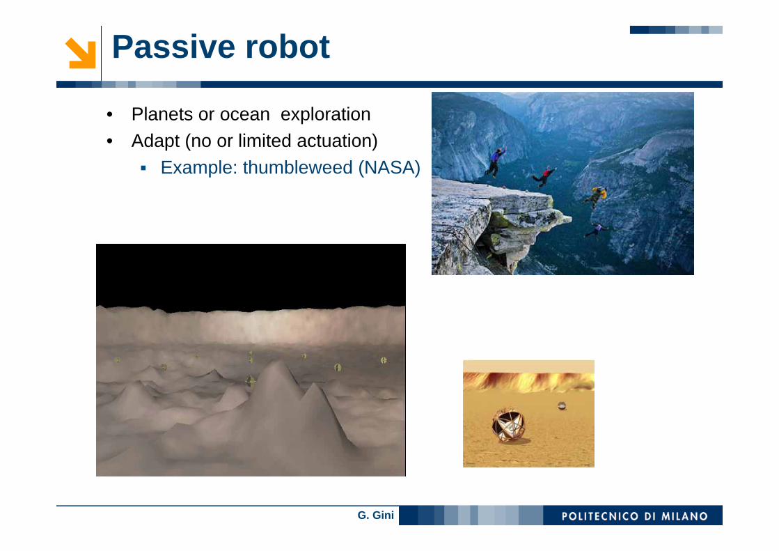
Passive robot
• Planets or ocean exploration• Adapt (no or limited actuation)
Example: thumbleweed (NASA)
G. Gini
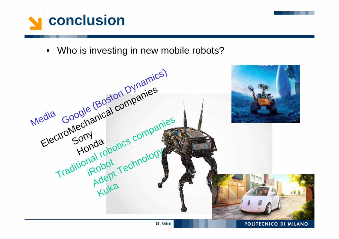
conclusion
• Who is investing in new mobile robots?
Media Google (Boston Dynamics)
ElectroMechanical companies
Sony
Honda
Traditional robotics companies
iRobot
Adept Technology
Kuka